EP2999835B1 - Security device - Google Patents
Security deviceDownload PDFInfo
- Publication number
- EP2999835B1 EP2999835B1EP14727755.2AEP14727755AEP2999835B1EP 2999835 B1EP2999835 B1EP 2999835B1EP 14727755 AEP14727755 AEP 14727755AEP 2999835 B1EP2999835 B1EP 2999835B1
- Authority
- EP
- European Patent Office
- Prior art keywords
- jack plug
- locking
- security device
- engagement
- locking member
- Prior art date
- Legal status (The legal status is an assumption and is not a legal conclusion. Google has not performed a legal analysis and makes no representation as to the accuracy of the status listed.)
- Active
Links
Images


Classifications
- E—FIXED CONSTRUCTIONS
- E05—LOCKS; KEYS; WINDOW OR DOOR FITTINGS; SAFES
- E05B—LOCKS; ACCESSORIES THEREFOR; HANDCUFFS
- E05B73/00—Devices for locking portable objects against unauthorised removal; Miscellaneous locking devices
- H—ELECTRICITY
- H01—ELECTRIC ELEMENTS
- H01R—ELECTRICALLY-CONDUCTIVE CONNECTIONS; STRUCTURAL ASSOCIATIONS OF A PLURALITY OF MUTUALLY-INSULATED ELECTRICAL CONNECTING ELEMENTS; COUPLING DEVICES; CURRENT COLLECTORS
- H01R13/00—Details of coupling devices of the kinds covered by groups H01R12/70 or H01R24/00 - H01R33/00
- H01R13/62—Means for facilitating engagement or disengagement of coupling parts or for holding them in engagement
- H01R13/629—Additional means for facilitating engagement or disengagement of coupling parts, e.g. aligning or guiding means, levers, gas pressure electrical locking indicators, manufacturing tolerances
- E—FIXED CONSTRUCTIONS
- E05—LOCKS; KEYS; WINDOW OR DOOR FITTINGS; SAFES
- E05B—LOCKS; ACCESSORIES THEREFOR; HANDCUFFS
- E05B73/00—Devices for locking portable objects against unauthorised removal; Miscellaneous locking devices
- E05B73/0017—Anti-theft devices, e.g. tags or monitors, fixed to articles, e.g. clothes, and to be removed at the check-out of shops
- E05B73/0047—Unlocking tools; Decouplers
- E—FIXED CONSTRUCTIONS
- E05—LOCKS; KEYS; WINDOW OR DOOR FITTINGS; SAFES
- E05B—LOCKS; ACCESSORIES THEREFOR; HANDCUFFS
- E05B73/00—Devices for locking portable objects against unauthorised removal; Miscellaneous locking devices
- E05B73/0082—Devices for locking portable objects against unauthorised removal; Miscellaneous locking devices for office machines, e.g. PC's, portable computers, typewriters, calculators
- H—ELECTRICITY
- H01—ELECTRIC ELEMENTS
- H01R—ELECTRICALLY-CONDUCTIVE CONNECTIONS; STRUCTURAL ASSOCIATIONS OF A PLURALITY OF MUTUALLY-INSULATED ELECTRICAL CONNECTING ELEMENTS; COUPLING DEVICES; CURRENT COLLECTORS
- H01R13/00—Details of coupling devices of the kinds covered by groups H01R12/70 or H01R24/00 - H01R33/00
- H01R13/62—Means for facilitating engagement or disengagement of coupling parts or for holding them in engagement
- H01R13/639—Additional means for holding or locking coupling parts together, after engagement, e.g. separate keylock, retainer strap
- H01R13/6397—Additional means for holding or locking coupling parts together, after engagement, e.g. separate keylock, retainer strap with means for preventing unauthorised use
- H—ELECTRICITY
- H01—ELECTRIC ELEMENTS
- H01R—ELECTRICALLY-CONDUCTIVE CONNECTIONS; STRUCTURAL ASSOCIATIONS OF A PLURALITY OF MUTUALLY-INSULATED ELECTRICAL CONNECTING ELEMENTS; COUPLING DEVICES; CURRENT COLLECTORS
- H01R24/00—Two-part coupling devices, or either of their cooperating parts, characterised by their overall structure
- H01R24/58—Contacts spaced along longitudinal axis of engagement
Definitions
- the inventionrelates to a security device for securing a jack plug during retail display of a product fitted with a jack plug.
- One type of retail product that is fitted with a jack plugis a pair of headphones.
- a pair of headphonesit is desirable to allow a potential customer to listen to music through the headphones so that the customer can assess the sound quality.
- the customermay wish, for example, to plug the headphones into his or her MP3 player or mobile phone so that the customer can listen, through the headphones, to music with which the customer is familiar.
- a security devicefor securing a jack plug during retail display of a product fitted with a jack plug, the security device comprising: a jack plug socket for engagement with a jack plug and operable to lock a jack plug in said engagement so as to resist withdrawal of the jack plug, an input for receiving electrical signals, the input being electrically connected to the jack plug socket so that electrical signals received at the input are transmitted to the jack plug socket for transmission of the electrical signals from the jack plug socket to a jack plug locked in engagement with the jack plug socket and for onward transmission of the electrical signals to a product connected to the jack plug, and an attachment for attaching the security device to a fixture, the jack plug socket comprising a locking member moveable between
- the jack plug socketfurthermore comprises a rotatable control member which interacts with the locking member.
- the rotatable control memberis rotatable between a first stop at which the locking member is locked in the locking position and a second stop at which the locking member is in the release position.
- the provision of the two distinct stopsis advantageous compared to, for example, a locking screw which can be tightened or loosened without any distinct stops to limit its rotation. The provision of these stops avoids over tightening.
- the security device of the current inventionallows a retail product to be secured by securing the jack plug connected to the product. It will be appreciated that the security device can be used with other retail products fitted with a jack plug. The use is not limited to pairs of headphones.
- jack plugis used to signify an electrical male plug having a single, generally cylindrical pin provided with a plurality of contact areas along its length and the term “jack plug socket” is used to refer to the corresponding female socket.
- Jack plugsare also commonly known as audio jacks or phone jacks.
- the term jack plugincludes all sizes (e.g. with 2.5mm, 3.5mm and 6.35mm diameter pins).
- the term jack plugalso covers plugs with any plural number of contacts.
- an audio stereo jack plugcommonly has three contacts and is often referred to as a TRS plug (the initials TRS referring to the three contact areas of the pin known as Tip, Ring and Sleeve).
- An audio mono jack plugcommonly has two contacts and is often referred to as a TS (Tip, Sleeve) plug.
- a four contact plugis commonly referred to as a TRRS (Tip, Ring, Ring, Sleeve) plug.
- TRRSTip, Ring, Ring, Sleeve
- Jack plugs having greater numbers of contactsare available. All such plugs are included within the term “jack plug” and the corresponding jack plug sockets are included within the term “jack plug socket”.
- the terms “jack plug” and “jack plug socket”are not limited to audio plugs and sockets and also cover all other uses, such as a microphone plug having a cylindrical configuration and the corresponding socket.
- the tip of a jack plugis separated from ring and sleeve contacts on the jack plug by a neck.
- the tipgenerally includes a convex frusto-conical surface which faces generally radially outwardly and rearwardly (ie towards a handle portion of the jack plug).
- the security deviceincludes a housing.
- the jack plug socketis provided in the housing and the attachment allows attachment of the housing to a fixture. In this way, the housing protects and hides the locking mechanism of the jack plug socket.
- the locking memberWhen the locking member is in the locking position, the locking member engages a tip of a jack plug.
- the shape of the tip of the jack plugallows the locking member to achieve purchase on the jack plug. In this way, locking of the jack plug within the jack plug socket can generally be achieved without deforming the pin of the jack plug.
- the locking memberpreferably has a concave frusto-conical surface.
- the security deviceis used with a jack plug having a tip which has a convex frusto-conical surface.
- the locking memberBy providing the locking member with a concave frusto-conical surface which corresponds closely in shape to the convex frusto-conical surface of the tip of the pin of a jack plug, it has been found possible to achieve secure locking of a jack plug within a jack plug socket.
- the locking memberpreferably has a first end and a second end. The first end is pivoted and the second end of the locking member interacts with the rotatable control member to control movement of the locking member between the locking position and the release position. Where a concave frusto-conical surface is provided on the locking member, this is preferably intermediate the first and second ends of the locking member. In this way, a high degree of positional accuracy of the frusto-conical surface may be achieved.
- the security devicepreferably also includes a security key.
- the rotatable control memberhas a formation which is shaped for engagement with the security key so that the rotatable control member can be rotated by the security key between the first and second stops. Even more preferably, the shape of the formation on the rotatable control member is such that it cannot be engaged by a screwdriver with a slot head or a cross-head. In this way, even if a potential customer is able to gain access to the jack plug socket, the customer may not be able to release the jack plug without a security key which corresponds to the formation on the rotatable control member.
- the input of the security devicemay be any suitable input. It could, for example, be a standard jack plug socket without a locking function. It could also be, for example, a standard USB socket. In one specific embodiment, the input is itself a jack plug which a potential customer can plug into his or her MP3 player or mobile phone.
- a method of securing a jack plug during retail display of a product fitted with a jack plugcomprising providing a product fitted with a jack plug, providing a security device, securing the security device to a fixture, locking the jack plug in engagement with the security device, and providing an input.
- the inputbeing electrically connected to the jack plug so that electrical signals received at the input are transmitted to the jack plug for onward transmission of the electrical signals to the product.
- the security deviceincludes a casing bottom 10, an intermediate lid 12, an outer lid 14, a locking jack plug socket generally shown at 16, and an input in the form of a standard jack plug socket 18.
- the casing bottom 10is provided with two upstanding attachment bosses 20.
- Each attachment boss 20has a central hole which passes through the casing bottom 10.
- the attachment bosses 20can be used to attach the casing bottom 10 to a fixture, such as a wooden display stand, by passing two screws through the attachment bosses 20 into the underlying wooden fixture.
- the casing bottom 10is provided with two upstanding support bosses 22.
- Each support boss 22is provided with a blind threaded hole which, as seen best in Figure 9 , receives a threaded bolt so as to attach the intermediate lid 12 to the casing bottom 10.
- the casing bottom 10also has an L-shaped rebate 24 which extends around the casing bottom 10 and which receives the outer lid 14 as described below in more detail.
- the casing bottom 10also has a first aperture 26 which receives the pin of a jack plug to be engaged in the locking jack plug socket 16 and a second aperture 28 which receives the pin of a jack plug to be engaged in the standard jack plug socket 18.
- the standard jack plug socket 18is omitted from Figure 3 for the purposes of clarity.
- connection plate 30is provided near to but spaced from a bottom wall of the casing bottom 10.
- the locking jack plug socket 16 and the standard jack plug socket 18are both mounted on the connection plate 30.
- Electrical connections(not shown) are provided on the underside of the connection plate 30 to connect the locking jack plug socket 16 with the standard jack plug socket 18. In this way, electrical input signals provided to the standard jack plug socket 18 by a jack plug inserted in the standard jack plug socket 18 are transmitted to the locking jack plug socket 16 so that the locking jack plug socket 16 can transmit the electrical signals to a jack plug engaged with the locking jack plug socket 16.
- the standard jack plug socket 18is conventional in design and will not be described in detail.
- the locking jack plug socket 16includes a locking arm 32, a control screw 34 and a pair of pivot mounts 36.
- the locking arm 32is best seen in Figure 6 which shows the underside of the locking arm 32.
- a first end of the locking arm 32is provided with a pair of pivot pins 38.
- the pair of pivot pins 38co-operate with the pivot mounts 36 to allow the locking arm 32 to pivot around the axes of the pivot pins 38.
- the pivot mounts 36do not prevent upward movement of the pivot pins 38 out of engagement with the pivot mounts 36.
- two projectionsare provided on the underside of the intermediate lid 12 so that when the intermediate lid 12 is fixed to the casing bottom 10 as described above, the projections on the underside of the intermediate lid 12 bear against the pair of pivot pins 38 and prevent any upward movement of the pivot pins 38. In this way, the locking arm 32 is constrained so that only pivoting movement around the axes of the pivot pins 38 is allowed.
- the second end of the locking arm 32is provided with a locking ring 40.
- the locking ring 40cooperates with the control screw 34, as described below, to achieve movement of the locking arm 32 between a locking position and a release position.
- the underside of the locking arm 32is provided with a frusto-conical recess 42. This serves a purpose described below.
- the control screw 34is best seen in Figures 1 , 4 , 5 , 7 and 8 .
- the locking screw 34is engaged, by way of corresponding screw threads, with a nut 44 which is fixed to the bottom wall of the casing bottom 10. In this way, if the control screw 34 is rotated in a clockwise direction (as seen from above), the control screw 34 moves downwardly into the nut 44. If the control screw 34 is rotated in an anti-clockwise direction (as seen from above), then the control screw 34 moves upwardly relative to the nut 44.
- the top end of the control screw 34is provided with a security formation in the form of a truncated pyramid 46.
- This truncated pyramid 46is shaped so as to engage with a security key (not shown).
- the security keyis used to rotate the control screw 34 either in a clockwise or anti-clockwise direction.
- control screw 34is provided with a locking disc 48.
- the locking disc 48cooperates with the locking ring 40 of the locking arm 32 to control movement of the locking arm 32 between a locking position and a release position, as will now be described.
- the locking ring 40 of the locking arm 32has, on its upper surface, a cam surface 50. Adjacent to the cam surface 50, the locking ring 40 of the locking arm 32 also has a stop surface 52.
- the underside of the locking disc 48 of the control screw 34also has a cam surface 54. Adjacent to cam surface 54, the locking disc 48 of the control screw 34 has a stop surface 56 which can be seen in Figure 7 .
- Figures 5 , 7 and 8show the locking arm 32 in a release position.
- Figures 5 and 8also show a jack plug 60 which is engaged with, but not locked with, the locking jack plug socket 16.
- the jack plug 60can be withdrawn from the locking jack plug socket 16 simply by pulling the jack plug 60 out of the locking jack plug socket 16.
- the security key(not shown) can be engaged with the truncated pyramid 46 of the control screw 34 and the security key is then used to rotate the control screw 34 in a clockwise direction (as seen from above). This causes the control screw 34 and the locking disc 48 to move downwardly into/towards the nut 44. During this process, the cam surface 54 on the locking disc 48 moves against and along the cam surface 50 on the locking ring 40 of the locking arm 32. The engagement of the two cam surfaces 50, 54 and the downward movement of the control screw 34, moves the locking arm 32 downwardly from the position shown in Figure 8 . The distance of movement is relatively small.
- the jack plug 60is of conventional design and has a jack plug tip shown at 62.
- the jack plug tip 62has a convex frusto-conical surface indicated at 64.
- the concave frusto-conical surface of the recess 42 of the locking arm 32fits closely against the convex frusto-conical surface 64 of the tip 62 of the jack plug 60.
- the two frusto-conical surfaces 42, 64correspond closely in shape and this provides an effective locking mechanism preventing withdrawal of the jack plug 60 from the locking jack plug socket 16.
- a bracing rib 66extends upwardly from the bottom wall of the casing bottom 10 and this bracing rib 66 serves to prevent downward movement of the jack plug 60 which would otherwise reduce the effectiveness of the locking of the jack plug 60 within the locking jack plug socket 16. It will be appreciated that additional bracing ribs may be provided, either extending upwardly from the casing bottom 10, or extending downwardly from the underside of the intermediate lid 12. In this way, any tilting of the jack plug 60 when engaged within the locking jack plug 16 may be prevented.
- the jack plug 60is of a type referred to as TRS.
- the tip 62forms a first electrical contact
- a ring 68forms a second electrical contact
- a sleeve 70forms a third electrical contact.
- the locking jack plug socket 16has first, second and third electrical contacts 72, 74, 76.
- the first electrical contact 72forms an electrical contact with the tip 62.
- the second electrical contact 74forms an electrical connection with the ring 68 and the third electrical contact 76 forms an electrical connection with the sleeve 70.
- Each one of the first, second and third electrical contacts 72, 74, 76is spring loaded urging the electrical contacts 72, 74, 76 against the corresponding part of the jack plug 60.
- the electrical contacts 72, 74, 76are in electrical connection with the electrical connectors on the underside of the connection plate 30.
- Figure 9also shows two bolts 80 which pass through respective holes in the intermediate lid 12 and are received in the support bosses 22 in order to fix the intermediate lid 12 securely against the casing bottom 10.
- the intermediate lid 12has three bayonet type slots 82 which cooperate with three corresponding bayonet projections (not shown) on the underside of the outer lid 14 in order to fix the outer lid 14 to the casing bottom 10.
- the intermediate lid 12also has an aperture 84 which corresponds in position with the truncated pyramid 46 of the control screw 34 so that the security key can be passed through the aperture 84 to operate the control screw 34.
- a slot 86is also provided in the intermediate lid 12 to facilitate lifting of the intermediate lid 12 out of the casing bottom 10.
- the security deviceis fixed to a fixture using the attachment bosses 20 as described above.
- the security deviceis used to secure a pair of headphones on retail display.
- the jack plug 60 of the headphonesis inserted into the locking jack plug socket 16.
- a retail assistantthen removes the outer lid 14 by rotating the outer lid 14 so as to reveal the intermediate lid 12. There is no need to remove the intermediate lid 12.
- the retail assistantuses the security key to rotate the control screw 34 in a clockwise direction which causes the locking arm 32 to move from the release position to the locking position as described above.
- the jack plug 60is now locked in the locking jack plug socket 16.
- the retail assistantreplaces the outer lid 14.
- a potential customeris now able to listen to music through the headphones.
- a connecting cable(not shown) having a jack plug at each end is used.
- One of the jack plugs of the connecting cableis inserted into the standard jack plug socket 18 of the security device.
- the other jack plug of the connecting cableis inserted into the customer's MP3 player or mobile phone.
- Electrical signals carried by the connecting cable to the standard jack plug socket 18are passed to the locking jack plug socket 16 and the music can be heard in the headphones.
- the locking of the jack plug 60 in the locking jack plug socket 16prevents theft of the headphones.
- any locking mechanism capable of holding a jack plug within a locking jack plug socketmay be used.
- the security devicemay be provided with a jack plug of its own connected to the locking jack plug socket 16 by a cable fixed to the casing. The jack plug of the security device can then be simply inserted into the MP3 player or mobile phone of the customer.
- the security devicecould be provided with any other type of input, such as a USB socket or USB plug.
Landscapes
- Engineering & Computer Science (AREA)
- Computer Security & Cryptography (AREA)
- Computer Hardware Design (AREA)
- Details Of Connecting Devices For Male And Female Coupling (AREA)
Description
- The invention relates to a security device for securing a jack plug during retail display of a product fitted with a jack plug.
- One type of retail product that is fitted with a jack plug is a pair of headphones. During retail display of a pair of headphones, it is desirable to allow a potential customer to listen to music through the headphones so that the customer can assess the sound quality. The customer may wish, for example, to plug the headphones into his or her MP3 player or mobile phone so that the customer can listen, through the headphones, to music with which the customer is familiar.
- When allowing customers to try out headphones as described above, it is also desirable to secure the headphones to a fixture, such as a display stand, so that the headphones cannot be stolen.
- Document
US 6 790 070 B1 discloses a device for locking a jack plug for use with a jack plug and a jack plug signal receptacle for prevention of intentional or inadvertent removal of the jack plug. In accordance with a first aspect of the invention, there is provided a security device for securing a jack plug during retail display of a product fitted with a jack plug, the security device comprising: a jack plug socket for engagement with a jack plug and operable to lock a jack plug in said engagement so as to resist withdrawal of the jack plug, an input for receiving electrical signals, the input being electrically connected to the jack plug socket so that electrical signals received at the input are transmitted to the jack plug socket for transmission of the electrical signals from the jack plug socket to a jack plug locked in engagement with the jack plug socket and for onward transmission of the electrical signals to a product connected to the jack plug, and an attachment for attaching the security device to a fixture, the jack plug socket comprising a locking member moveable between a locking position and a release position for release of a jack plug from the jack plug socket, the locking member being lockable in the locking position in engagement with a tip of a jack plug to effect said locking of the jack plug in said engagement with the jack plug socket. The jack plug socket furthermore comprises a rotatable control member which interacts with the locking member. The rotatable control member is rotatable between a first stop at which the locking member is locked in the locking position and a second stop at which the locking member is in the release position. The provision of the two distinct stops is advantageous compared to, for example, a locking screw which can be tightened or loosened without any distinct stops to limit its rotation. The provision of these stops avoids over tightening. - Accordingly, the security device of the current invention allows a retail product to be secured by securing the jack plug connected to the product. It will be appreciated that the security device can be used with other retail products fitted with a jack plug. The use is not limited to pairs of headphones.
- The term "jack plug" is used to signify an electrical male plug having a single, generally cylindrical pin provided with a plurality of contact areas along its length and the term "jack plug socket" is used to refer to the corresponding female socket. Jack plugs are also commonly known as audio jacks or phone jacks. The term jack plug includes all sizes (e.g. with 2.5mm, 3.5mm and 6.35mm diameter pins). The term jack plug also covers plugs with any plural number of contacts. For example, an audio stereo jack plug commonly has three contacts and is often referred to as a TRS plug (the initials TRS referring to the three contact areas of the pin known as Tip, Ring and Sleeve). An audio mono jack plug commonly has two contacts and is often referred to as a TS (Tip, Sleeve) plug. A four contact plug is commonly referred to as a TRRS (Tip, Ring, Ring, Sleeve) plug. Jack plugs having greater numbers of contacts are available. All such plugs are included within the term "jack plug" and the corresponding jack plug sockets are included within the term "jack plug socket". The terms "jack plug" and "jack plug socket" are not limited to audio plugs and sockets and also cover all other uses, such as a microphone plug having a cylindrical configuration and the corresponding socket. In general, the tip of a jack plug is separated from ring and sleeve contacts on the jack plug by a neck. The tip generally includes a convex frusto-conical surface which faces generally radially outwardly and rearwardly (ie towards a handle portion of the jack plug).
- Preferably, the security device includes a housing. The jack plug socket is provided in the housing and the attachment allows attachment of the housing to a fixture. In this way, the housing protects and hides the locking mechanism of the jack plug socket.
- When the locking member is in the locking position, the locking member engages a tip of a jack plug. In this case, the shape of the tip of the jack plug allows the locking member to achieve purchase on the jack plug. In this way, locking of the jack plug within the jack plug socket can generally be achieved without deforming the pin of the jack plug. The locking member preferably has a concave frusto-conical surface. In this case, the security device is used with a jack plug having a tip which has a convex frusto-conical surface. By providing the locking member with a concave frusto-conical surface which corresponds closely in shape to the convex frusto-conical surface of the tip of the pin of a jack plug, it has been found possible to achieve secure locking of a jack plug within a jack plug socket. The locking member preferably has a first end and a second end. The first end is pivoted and the second end of the locking member interacts with the rotatable control member to control movement of the locking member between the locking position and the release position. Where a concave frusto-conical surface is provided on the locking member, this is preferably intermediate the first and second ends of the locking member. In this way, a high degree of positional accuracy of the frusto-conical surface may be achieved. The security device preferably also includes a security key. The rotatable control member has a formation which is shaped for engagement with the security key so that the rotatable control member can be rotated by the security key between the first and second stops. Even more preferably, the shape of the formation on the rotatable control member is such that it cannot be engaged by a screwdriver with a slot head or a cross-head. In this way, even if a potential customer is able to gain access to the jack plug socket, the customer may not be able to release the jack plug without a security key which corresponds to the formation on the rotatable control member.
- The input of the security device may be any suitable input. It could, for example, be a standard jack plug socket without a locking function. It could also be, for example, a standard USB socket. In one specific embodiment, the input is itself a jack plug which a potential customer can plug into his or her MP3 player or mobile phone.
- In accordance with a second aspect of the invention, there is provided a method of securing a jack plug during retail display of a product fitted with a jack plug, comprising providing a product fitted with a jack plug, providing a security device, securing the security device to a fixture, locking the jack plug in engagement with the security device, and providing an input. The input being electrically connected to the jack plug so that electrical signals received at the input are transmitted to the jack plug for onward transmission of the electrical signals to the product.
- The following is a more detailed description of embodiments of the invention, by way of example, reference being made to the following schematic drawings in which:
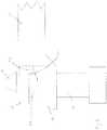
Figure 1 is an isometric view of a security device from which an external lid and an intermediate lid have been omitted in order to show the internal components;Figure 2 is a plan view from above of the security device ofFigure 1 ;Figure 3 is a cross-sectional view of the security device ofFigures 1 and2 ;Figures 4 to 8 are isometric views showing components of a jack plug socket of the security device ofFigures 1 to 3 ;Figure 9 is a plan view from above of the security device ofFigures 1 to 8 showing an intermediate cover in place in the security device;Figure 10 is a plan view from above of the security device ofFigures 1 to 9 showing an outer cover in place on the security device.- Looking first at
Figures 1 ,2 ,9 and10 , the security device includes acasing bottom 10, anintermediate lid 12, anouter lid 14, a locking jack plug socket generally shown at 16, and an input in the form of a standard jack plug socket 18. - As best seen in
Figure 1 , thecasing bottom 10 is provided with twoupstanding attachment bosses 20. Eachattachment boss 20 has a central hole which passes through thecasing bottom 10. In this way, theattachment bosses 20 can be used to attach thecasing bottom 10 to a fixture, such as a wooden display stand, by passing two screws through theattachment bosses 20 into the underlying wooden fixture. In addition, thecasing bottom 10 is provided with twoupstanding support bosses 22. Eachsupport boss 22 is provided with a blind threaded hole which, as seen best inFigure 9 , receives a threaded bolt so as to attach theintermediate lid 12 to thecasing bottom 10. Thecasing bottom 10 also has an L-shaped rebate 24 which extends around thecasing bottom 10 and which receives theouter lid 14 as described below in more detail. - As best seen in
Figures 1 and3 , thecasing bottom 10 also has afirst aperture 26 which receives the pin of a jack plug to be engaged in the lockingjack plug socket 16 and asecond aperture 28 which receives the pin of a jack plug to be engaged in the standard jack plug socket 18. The standard jack plug socket 18 is omitted fromFigure 3 for the purposes of clarity. - Looking now at
Figures 1 and3 , aconnection plate 30 is provided near to but spaced from a bottom wall of thecasing bottom 10. The lockingjack plug socket 16 and the standard jack plug socket 18 are both mounted on theconnection plate 30. Electrical connections (not shown) are provided on the underside of theconnection plate 30 to connect the lockingjack plug socket 16 with the standard jack plug socket 18. In this way, electrical input signals provided to the standard jack plug socket 18 by a jack plug inserted in the standard jack plug socket 18 are transmitted to the lockingjack plug socket 16 so that the lockingjack plug socket 16 can transmit the electrical signals to a jack plug engaged with the lockingjack plug socket 16. - The standard jack plug socket 18 is conventional in design and will not be described in detail.
- Referring now to
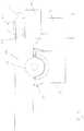
Figures 1 to 8 , the lockingjack plug socket 16 includes a lockingarm 32, acontrol screw 34 and a pair of pivot mounts 36. The lockingarm 32 is best seen inFigure 6 which shows the underside of the lockingarm 32. As shown inFigure 6 , a first end of the lockingarm 32 is provided with a pair of pivot pins 38. As shown inFigure 1 , the pair of pivot pins 38 co-operate with the pivot mounts 36 to allow thelocking arm 32 to pivot around the axes of the pivot pins 38. As seen inFigure 1 , the pivot mounts 36 do not prevent upward movement of the pivot pins 38 out of engagement with the pivot mounts 36. However, two projections (not shown) are provided on the underside of theintermediate lid 12 so that when theintermediate lid 12 is fixed to the casing bottom 10 as described above, the projections on the underside of theintermediate lid 12 bear against the pair of pivot pins 38 and prevent any upward movement of the pivot pins 38. In this way, the lockingarm 32 is constrained so that only pivoting movement around the axes of the pivot pins 38 is allowed. - The second end of the locking
arm 32 is provided with a lockingring 40. The lockingring 40 cooperates with thecontrol screw 34, as described below, to achieve movement of the lockingarm 32 between a locking position and a release position. - As shown in
Figure 6 , the underside of the lockingarm 32 is provided with a frusto-conical recess 42. This serves a purpose described below. - The
control screw 34 is best seen inFigures 1 ,4 ,5 ,7 and8 . As seen, for example, inFigures 1 and4 , the lockingscrew 34 is engaged, by way of corresponding screw threads, with anut 44 which is fixed to the bottom wall of thecasing bottom 10. In this way, if thecontrol screw 34 is rotated in a clockwise direction (as seen from above), thecontrol screw 34 moves downwardly into thenut 44. If thecontrol screw 34 is rotated in an anti-clockwise direction (as seen from above), then thecontrol screw 34 moves upwardly relative to thenut 44. - The top end of the
control screw 34 is provided with a security formation in the form of atruncated pyramid 46. Thistruncated pyramid 46 is shaped so as to engage with a security key (not shown). The security key is used to rotate thecontrol screw 34 either in a clockwise or anti-clockwise direction. - Immediately below the
truncated pyramid 46, thecontrol screw 34 is provided with alocking disc 48. Thelocking disc 48 cooperates with the lockingring 40 of the lockingarm 32 to control movement of the lockingarm 32 between a locking position and a release position, as will now be described. - As best seen in
Figures 5 and7 , the lockingring 40 of the lockingarm 32 has, on its upper surface, acam surface 50. Adjacent to thecam surface 50, the lockingring 40 of the lockingarm 32 also has astop surface 52. - As best seen in
Figure 8 , the underside of thelocking disc 48 of thecontrol screw 34 also has a cam surface 54. Adjacent to cam surface 54, thelocking disc 48 of thecontrol screw 34 has astop surface 56 which can be seen inFigure 7 . Figures 5 ,7 and8 show the lockingarm 32 in a release position.Figures 5 and8 also show a jack plug 60 which is engaged with, but not locked with, the lockingjack plug socket 16. In the release position of the lockingarm 40, as shown inFigures 5 ,7 and8 , the jack plug 60 can be withdrawn from the lockingjack plug socket 16 simply by pulling the jack plug 60 out of the lockingjack plug socket 16.- However, the security key (not shown) can be engaged with the
truncated pyramid 46 of thecontrol screw 34 and the security key is then used to rotate thecontrol screw 34 in a clockwise direction (as seen from above). This causes thecontrol screw 34 and thelocking disc 48 to move downwardly into/towards thenut 44. During this process, the cam surface 54 on thelocking disc 48 moves against and along thecam surface 50 on the lockingring 40 of the lockingarm 32. The engagement of the twocam surfaces 50, 54 and the downward movement of thecontrol screw 34, moves the lockingarm 32 downwardly from the position shown inFigure 8 . The distance of movement is relatively small. - This process continues until the
stop surface 56 on thelocking disc 48 of control screw 34 contacts thestop surface 52 on the lockingring 40 of the lockingarm 32. After contact between the two stop surfaces 52, 56 no further clockwise motion of thecontrol screw 34 is possible. At this point, the lockingarm 32 is in the locking position, and this is shown inFigure 3 . - As seen in
Figure 3 , the jack plug 60 is of conventional design and has a jack plug tip shown at 62. Thejack plug tip 62 has a convex frusto-conical surface indicated at 64. In the current locking position of the lockingarm 32, the concave frusto-conical surface of therecess 42 of the locking arm 32 (best seen inFigures 3 and6 ) fits closely against the convex frusto-conical surface 64 of thetip 62 of the jack plug 60. The two frusto-conical surfaces 42, 64 (one being convex and the other being concave) correspond closely in shape and this provides an effective locking mechanism preventing withdrawal of the jack plug 60 from the lockingjack plug socket 16. - As best seen in
Figures 3 and8 , a bracingrib 66 extends upwardly from the bottom wall of the casing bottom 10 and this bracingrib 66 serves to prevent downward movement of the jack plug 60 which would otherwise reduce the effectiveness of the locking of the jack plug 60 within the lockingjack plug socket 16. It will be appreciated that additional bracing ribs may be provided, either extending upwardly from the casing bottom 10, or extending downwardly from the underside of theintermediate lid 12. In this way, any tilting of the jack plug 60 when engaged within the lockingjack plug 16 may be prevented. - In order to unlock the locking
jack plug socket 16, so as to allow removal of the jack plug 60, thecontrol screw 34 is rotated in an anticlockwise direction whereupon the twocam surfaces 50, 54 move against each other back into the unlocking position shown inFigures 5 and8 . This causes a small upward movement of the lockingarm 32 which is sufficient to allow withdrawal of the jack plug 60. At the rotational position of thecontrol screw 34 shown inFigures 5 and8 , no further anticlockwise rotation of thecontrol screw 34 is possible due to contact between two additional stop surfaces (not shown). - As best seen in
Figure 3 and5 , the jack plug 60 is of a type referred to as TRS. In other words, thetip 62 forms a first electrical contact, a ring 68 forms a second electrical contact and asleeve 70 forms a third electrical contact. As best seen inFigure 3 , the lockingjack plug socket 16 has first, second and thirdelectrical contacts electrical contact 72 forms an electrical contact with thetip 62. The secondelectrical contact 74 forms an electrical connection with the ring 68 and the thirdelectrical contact 76 forms an electrical connection with thesleeve 70. Each one of the first, second and thirdelectrical contacts electrical contacts electrical contacts connection plate 30. - The upper surface of the
intermediate lid 12 is shown inFigure 9. Figure 9 also shows two bolts 80 which pass through respective holes in theintermediate lid 12 and are received in thesupport bosses 22 in order to fix theintermediate lid 12 securely against thecasing bottom 10. As seen inFigure 9 , theintermediate lid 12 has threebayonet type slots 82 which cooperate with three corresponding bayonet projections (not shown) on the underside of theouter lid 14 in order to fix theouter lid 14 to thecasing bottom 10. Theintermediate lid 12 also has anaperture 84 which corresponds in position with thetruncated pyramid 46 of thecontrol screw 34 so that the security key can be passed through theaperture 84 to operate thecontrol screw 34. - A slot 86 is also provided in the
intermediate lid 12 to facilitate lifting of theintermediate lid 12 out of thecasing bottom 10. - In operation, the security device is fixed to a fixture using the
attachment bosses 20 as described above. In this example, the security device is used to secure a pair of headphones on retail display. The jack plug 60 of the headphones is inserted into the lockingjack plug socket 16. A retail assistant then removes theouter lid 14 by rotating theouter lid 14 so as to reveal theintermediate lid 12. There is no need to remove theintermediate lid 12. The retail assistant uses the security key to rotate thecontrol screw 34 in a clockwise direction which causes the lockingarm 32 to move from the release position to the locking position as described above. The jack plug 60 is now locked in the lockingjack plug socket 16. The retail assistant replaces theouter lid 14. - A potential customer is now able to listen to music through the headphones. In order to do this, a connecting cable (not shown) having a jack plug at each end is used. One of the jack plugs of the connecting cable is inserted into the standard jack plug socket 18 of the security device. The other jack plug of the connecting cable is inserted into the customer's MP3 player or mobile phone. Electrical signals carried by the connecting cable to the standard jack plug socket 18 are passed to the locking
jack plug socket 16 and the music can be heard in the headphones. The locking of the jack plug 60 in the lockingjack plug socket 16 prevents theft of the headphones. - It will be appreciated that the security device need not be as described above and many adaptations may be made while remaining within the scope of the invention as defined by the appended claims.
- For example, while the locking mechanism described above has been found to be very effective, any locking mechanism capable of holding a jack plug within a locking jack plug socket may be used.
- In addition, it is not necessary to provide a standard jack plug socket 18. Instead, the security device may be provided with a jack plug of its own connected to the locking
jack plug socket 16 by a cable fixed to the casing. The jack plug of the security device can then be simply inserted into the MP3 player or mobile phone of the customer. - Alternatively, the security device could be provided with any other type of input, such as a USB socket or USB plug.
Claims (12)
- A security device for securing a jack plug (60) during retail display of a product fitted with a jack plug, the security device comprising: a jack plug socket (16) for engagement with a jack plug (60) and operable to lock a jack plug (60) in said engagement so as to prevent withdrawal of the jack plug, an input for receiving electrical signals, the input being electrically connected to the jack plug socket (16) so that electrical signals received at the input are transmitted to the jack plug socket (16) for transmission of the electrical signals from the jack plug socket (16) to a jack plug (60) locked in engagement within the jack plug socket (16) and for onward transmission of the electrical signals to a product connected to the jack plug (60), and an attachment for attaching the security device to a fixture, the jack plug socket (16) comprising a locking member (32) moveable between a locking position and a release position for release of a jack plug (60) from the jack plug socket (16), the locking member (32) being lockable in the locking position in engagement with a tip (62) of a jack plug (60) to effect said locking of the jack plug (60) in said engagement with the jack plug socket (16),characterised in that the jack plug socket (16) also comprises a rotatable control member (48) which interacts with the locking member (32), the rotatable control member (48) being rotatable between a first stop (52) at which the locking member (32) is locked in the locking position and a second stop (56) at which the locking member (32) is in the release position.
- A security device according to claim 1, further including a housing (10), the jack plug socket (16) being provided in the housing (10) and the attachment allowing attachment of the housing (10) to a fixture.
- A security device according to claim 1 or claim 2, wherein the locking member (32) has a concave frusto-conical surface (42) and wherein said engagement between the locking member (32) and the tip (62) of the jack plug (60) comprises engagement between the concave frusto-conical surface (42) of the locking member (32) and a corresponding convex frusto-conical surface (64) of the tip (62) of the jack plug (60).
- A security device according to 3, wherein the locking member (32) has a first end and a second end, the first end being pivoted and the second end interacting with the rotatable control member (48), the concave frusto-conical surface (42) being intermediate the first and second ends.
- A security device according to any preceding claim, wherein the locking member (32) and the rotatable control member (48) have respective cam surfaces (50, 54) which interact so that rotation of the rotatable control member (48) from the first stop (52) to the second stop (56) moves the locking member (32) from the locking position to the release position and rotation of the rotatable control member from the second stop (56) to the first stop (52) moves the locking member (32) from the release position to the locking position.
- A security device according to any preceding claim, further comprising a security key, wherein the rotatable control member (48) has a formation (46) for engagement with the security key so that the rotatable control member (48) can be rotated by the security key between the first and second stops (52, 56).
- A security device according to claim 2, or any claim dependent on claim 2, wherein the rotatable control member (48) and the locking member (32) are contained within the housing (10).
- A security device according to claim 2, or any claim dependent on claim 2, wherein the input is a further jack plug socket (18) provided in the housing (10).
- A security device according to any one of claims 1 to 7, wherein the input is a jack plug (60) for receiving electrical signals from an electrical device.
- A security device according to claim 9, when claim 9 is dependent on claim 2, wherein the input jack plug (60) is connected to the housing (10) by a flexible cable.
- A security device according to any preceding claim in combination with a jack plug (60) lockable in engagement with the jack plug socket (16).
- A method of securing a jack plug (60) during retail display of a product fitted with a jack plug, comprising: providing a product fitted with a jack plug; providing a security device according to any one of claims 1 to 10; securing the security device to a fixture; and locking the jack plug in engagement with the security device.
Applications Claiming Priority (2)
| Application Number | Priority Date | Filing Date | Title |
|---|---|---|---|
| GB1309246.5AGB2514390B (en) | 2013-05-22 | 2013-05-22 | Security device |
| PCT/EP2014/060309WO2014187805A1 (en) | 2013-05-22 | 2014-05-20 | Security device |
Publications (2)
| Publication Number | Publication Date |
|---|---|
| EP2999835A1 EP2999835A1 (en) | 2016-03-30 |
| EP2999835B1true EP2999835B1 (en) | 2017-11-22 |
Family
ID=48747180
Family Applications (1)
| Application Number | Title | Priority Date | Filing Date |
|---|---|---|---|
| EP14727755.2AActiveEP2999835B1 (en) | 2013-05-22 | 2014-05-20 | Security device |
Country Status (5)
| Country | Link |
|---|---|
| US (1) | US20160099519A1 (en) |
| EP (1) | EP2999835B1 (en) |
| CN (1) | CN105229248A (en) |
| GB (1) | GB2514390B (en) |
| WO (1) | WO2014187805A1 (en) |
Families Citing this family (1)
| Publication number | Priority date | Publication date | Assignee | Title |
|---|---|---|---|---|
| CN112543138A (en)* | 2020-11-03 | 2021-03-23 | 浙江三维万易联科技有限公司 | Socket type gateway, freezer, data acquisition system and method |
Family Cites Families (11)
| Publication number | Priority date | Publication date | Assignee | Title |
|---|---|---|---|---|
| IE883885L (en)* | 1988-12-29 | 1990-06-29 | Mcdaid Denis | Telephone lock |
| TW501799U (en)* | 2000-05-23 | 2002-09-01 | Hon Hai Prec Ind Co Ltd | Socket connector |
| TW559402U (en)* | 2001-08-31 | 2003-10-21 | Hon Hai Prec Ind Co Ltd | Electrical connector |
| US6690801B2 (en)* | 2001-11-28 | 2004-02-10 | Hon Hai Precision Ind. Co., Ltd. | Audio jack having improved arrangement of contacts |
| US6790070B1 (en)* | 2003-09-10 | 2004-09-14 | The United States Of America As Represented By The Secretary Of The Navy | Apparatus for locking a plug |
| JP4440160B2 (en)* | 2005-04-12 | 2010-03-24 | 矢崎総業株式会社 | connector |
| CN2850025Y (en)* | 2005-11-14 | 2006-12-20 | 富士康(昆山)电脑接插件有限公司 | Speech socket connector |
| US7285024B1 (en)* | 2006-03-29 | 2007-10-23 | Speed Tech Corp. | Audio jack connector |
| US7371125B2 (en)* | 2006-07-24 | 2008-05-13 | Hon Hai Precision Ind. Co., Ltd. | Miniature audio jack connector |
| CN101521335A (en)* | 2008-02-29 | 2009-09-02 | 鸿富锦精密工业(深圳)有限公司 | Connector and socket thereof |
| GB201108841D0 (en)* | 2011-05-26 | 2011-07-06 | Theobald James | Anti-theft devices and methods |
- 2013
- 2013-05-22GBGB1309246.5Apatent/GB2514390B/ennot_activeExpired - Fee Related
- 2014
- 2014-05-20CNCN201480029420.0Apatent/CN105229248A/enactivePending
- 2014-05-20EPEP14727755.2Apatent/EP2999835B1/enactiveActive
- 2014-05-20USUS14/890,764patent/US20160099519A1/ennot_activeAbandoned
- 2014-05-20WOPCT/EP2014/060309patent/WO2014187805A1/enactiveApplication Filing
Also Published As
| Publication number | Publication date |
|---|---|
| GB201309246D0 (en) | 2013-07-03 |
| CN105229248A (en) | 2016-01-06 |
| EP2999835A1 (en) | 2016-03-30 |
| US20160099519A1 (en) | 2016-04-07 |
| WO2014187805A1 (en) | 2014-11-27 |
| GB2514390B (en) | 2016-04-27 |
| GB2514390A (en) | 2014-11-26 |
Similar Documents
| Publication | Publication Date | Title |
|---|---|---|
| EP2715020B1 (en) | Anti-theft devices and methods | |
| US8193447B2 (en) | Electrical outlet plate control arrangement | |
| KR101303147B1 (en) | Locking apparatus for terminal | |
| EP3671299B1 (en) | Connector assembly and plug connector and core unit thereof | |
| AU2012260865A1 (en) | Anti-theft devices and methods | |
| US8398414B2 (en) | Locking mechanisms and locking caps for connectors | |
| TW201131916A (en) | Coaxial cable connector sleeve | |
| JP2001203033A (en) | Connector | |
| JP7042970B2 (en) | Connection assembly and microphone assembly | |
| TW201408854A (en) | Locking device of portable electronic device | |
| TWI765550B (en) | Electronically lockable, electrical plug | |
| EP2999835B1 (en) | Security device | |
| EP3284146A1 (en) | Extension cord, socket and cover of a socket | |
| CA2680871C (en) | Locking electrical receptacle | |
| JP4853785B2 (en) | Anti-theft cover | |
| GB2429341A (en) | Module locking to wall outlet | |
| JP2002216885A (en) | L-type plug removal preventing structure of electronic device | |
| JP3099606U (en) | Secure ring device with bypass interface | |
| NZ617979B2 (en) | Anti-theft devices and methods | |
| JP2004022377A (en) | Electric connector | |
| JPS631312A (en) | Wiring appliance for data communication | |
| US20180163434A1 (en) | Programmable lock with pull pin assembly | |
| CA2215250A1 (en) | Electrical receptacle with releasable locking mechanism | |
| JP2006120452A (en) | Wiring system | |
| CN103687371A (en) | Locking device for portable electronic device |
Legal Events
| Date | Code | Title | Description |
|---|---|---|---|
| PUAI | Public reference made under article 153(3) epc to a published international application that has entered the european phase | Free format text:ORIGINAL CODE: 0009012 | |
| 17P | Request for examination filed | Effective date:20151110 | |
| AK | Designated contracting states | Kind code of ref document:A1 Designated state(s):AL AT BE BG CH CY CZ DE DK EE ES FI FR GB GR HR HU IE IS IT LI LT LU LV MC MK MT NL NO PL PT RO RS SE SI SK SM TR | |
| AX | Request for extension of the european patent | Extension state:BA ME | |
| DAX | Request for extension of the european patent (deleted) | ||
| GRAP | Despatch of communication of intention to grant a patent | Free format text:ORIGINAL CODE: EPIDOSNIGR1 | |
| INTG | Intention to grant announced | Effective date:20170606 | |
| GRAS | Grant fee paid | Free format text:ORIGINAL CODE: EPIDOSNIGR3 | |
| GRAA | (expected) grant | Free format text:ORIGINAL CODE: 0009210 | |
| AK | Designated contracting states | Kind code of ref document:B1 Designated state(s):AL AT BE BG CH CY CZ DE DK EE ES FI FR GB GR HR HU IE IS IT LI LT LU LV MC MK MT NL NO PL PT RO RS SE SI SK SM TR | |
| REG | Reference to a national code | Ref country code:GB Ref legal event code:FG4D | |
| REG | Reference to a national code | Ref country code:CH Ref legal event code:EP | |
| REG | Reference to a national code | Ref country code:IE Ref legal event code:FG4D | |
| REG | Reference to a national code | Ref country code:AT Ref legal event code:REF Ref document number:948571 Country of ref document:AT Kind code of ref document:T Effective date:20171215 | |
| REG | Reference to a national code | Ref country code:DE Ref legal event code:R096 Ref document number:602014017570 Country of ref document:DE | |
| REG | Reference to a national code | Ref country code:NL Ref legal event code:MP Effective date:20171122 | |
| REG | Reference to a national code | Ref country code:LT Ref legal event code:MG4D | |
| REG | Reference to a national code | Ref country code:AT Ref legal event code:MK05 Ref document number:948571 Country of ref document:AT Kind code of ref document:T Effective date:20171122 | |
| PG25 | Lapsed in a contracting state [announced via postgrant information from national office to epo] | Ref country code:NL Free format text:LAPSE BECAUSE OF FAILURE TO SUBMIT A TRANSLATION OF THE DESCRIPTION OR TO PAY THE FEE WITHIN THE PRESCRIBED TIME-LIMIT Effective date:20171122 Ref country code:SE Free format text:LAPSE BECAUSE OF FAILURE TO SUBMIT A TRANSLATION OF THE DESCRIPTION OR TO PAY THE FEE WITHIN THE PRESCRIBED TIME-LIMIT Effective date:20171122 Ref country code:ES Free format text:LAPSE BECAUSE OF FAILURE TO SUBMIT A TRANSLATION OF THE DESCRIPTION OR TO PAY THE FEE WITHIN THE PRESCRIBED TIME-LIMIT Effective date:20171122 Ref country code:FI Free format text:LAPSE BECAUSE OF FAILURE TO SUBMIT A TRANSLATION OF THE DESCRIPTION OR TO PAY THE FEE WITHIN THE PRESCRIBED TIME-LIMIT Effective date:20171122 Ref country code:NO Free format text:LAPSE BECAUSE OF FAILURE TO SUBMIT A TRANSLATION OF THE DESCRIPTION OR TO PAY THE FEE WITHIN THE PRESCRIBED TIME-LIMIT Effective date:20180222 Ref country code:LT Free format text:LAPSE BECAUSE OF FAILURE TO SUBMIT A TRANSLATION OF THE DESCRIPTION OR TO PAY THE FEE WITHIN THE PRESCRIBED TIME-LIMIT Effective date:20171122 | |
| REG | Reference to a national code | Ref country code:FR Ref legal event code:PLFP Year of fee payment:5 | |
| PG25 | Lapsed in a contracting state [announced via postgrant information from national office to epo] | Ref country code:AT Free format text:LAPSE BECAUSE OF FAILURE TO SUBMIT A TRANSLATION OF THE DESCRIPTION OR TO PAY THE FEE WITHIN THE PRESCRIBED TIME-LIMIT Effective date:20171122 Ref country code:HR Free format text:LAPSE BECAUSE OF FAILURE TO SUBMIT A TRANSLATION OF THE DESCRIPTION OR TO PAY THE FEE WITHIN THE PRESCRIBED TIME-LIMIT Effective date:20171122 Ref country code:BG Free format text:LAPSE BECAUSE OF FAILURE TO SUBMIT A TRANSLATION OF THE DESCRIPTION OR TO PAY THE FEE WITHIN THE PRESCRIBED TIME-LIMIT Effective date:20180222 Ref country code:RS Free format text:LAPSE BECAUSE OF FAILURE TO SUBMIT A TRANSLATION OF THE DESCRIPTION OR TO PAY THE FEE WITHIN THE PRESCRIBED TIME-LIMIT Effective date:20171122 Ref country code:LV Free format text:LAPSE BECAUSE OF FAILURE TO SUBMIT A TRANSLATION OF THE DESCRIPTION OR TO PAY THE FEE WITHIN THE PRESCRIBED TIME-LIMIT Effective date:20171122 Ref country code:GR Free format text:LAPSE BECAUSE OF FAILURE TO SUBMIT A TRANSLATION OF THE DESCRIPTION OR TO PAY THE FEE WITHIN THE PRESCRIBED TIME-LIMIT Effective date:20180223 | |
| PGFP | Annual fee paid to national office [announced via postgrant information from national office to epo] | Ref country code:LU Payment date:20180529 Year of fee payment:5 | |
| PG25 | Lapsed in a contracting state [announced via postgrant information from national office to epo] | Ref country code:CY Free format text:LAPSE BECAUSE OF FAILURE TO SUBMIT A TRANSLATION OF THE DESCRIPTION OR TO PAY THE FEE WITHIN THE PRESCRIBED TIME-LIMIT Effective date:20171122 Ref country code:DK Free format text:LAPSE BECAUSE OF FAILURE TO SUBMIT A TRANSLATION OF THE DESCRIPTION OR TO PAY THE FEE WITHIN THE PRESCRIBED TIME-LIMIT Effective date:20171122 Ref country code:EE Free format text:LAPSE BECAUSE OF FAILURE TO SUBMIT A TRANSLATION OF THE DESCRIPTION OR TO PAY THE FEE WITHIN THE PRESCRIBED TIME-LIMIT Effective date:20171122 Ref country code:CZ Free format text:LAPSE BECAUSE OF FAILURE TO SUBMIT A TRANSLATION OF THE DESCRIPTION OR TO PAY THE FEE WITHIN THE PRESCRIBED TIME-LIMIT Effective date:20171122 Ref country code:SK Free format text:LAPSE BECAUSE OF FAILURE TO SUBMIT A TRANSLATION OF THE DESCRIPTION OR TO PAY THE FEE WITHIN THE PRESCRIBED TIME-LIMIT Effective date:20171122 | |
| PGFP | Annual fee paid to national office [announced via postgrant information from national office to epo] | Ref country code:IE Payment date:20180529 Year of fee payment:5 Ref country code:DE Payment date:20180529 Year of fee payment:5 Ref country code:CH Payment date:20180601 Year of fee payment:5 Ref country code:MC Payment date:20180523 Year of fee payment:5 | |
| REG | Reference to a national code | Ref country code:DE Ref legal event code:R097 Ref document number:602014017570 Country of ref document:DE | |
| PG25 | Lapsed in a contracting state [announced via postgrant information from national office to epo] | Ref country code:PL Free format text:LAPSE BECAUSE OF FAILURE TO SUBMIT A TRANSLATION OF THE DESCRIPTION OR TO PAY THE FEE WITHIN THE PRESCRIBED TIME-LIMIT Effective date:20171122 Ref country code:SM Free format text:LAPSE BECAUSE OF FAILURE TO SUBMIT A TRANSLATION OF THE DESCRIPTION OR TO PAY THE FEE WITHIN THE PRESCRIBED TIME-LIMIT Effective date:20171122 Ref country code:RO Free format text:LAPSE BECAUSE OF FAILURE TO SUBMIT A TRANSLATION OF THE DESCRIPTION OR TO PAY THE FEE WITHIN THE PRESCRIBED TIME-LIMIT Effective date:20171122 Ref country code:IT Free format text:LAPSE BECAUSE OF FAILURE TO SUBMIT A TRANSLATION OF THE DESCRIPTION OR TO PAY THE FEE WITHIN THE PRESCRIBED TIME-LIMIT Effective date:20171122 | |
| PGFP | Annual fee paid to national office [announced via postgrant information from national office to epo] | Ref country code:BE Payment date:20180528 Year of fee payment:5 Ref country code:FR Payment date:20180525 Year of fee payment:5 | |
| PLBE | No opposition filed within time limit | Free format text:ORIGINAL CODE: 0009261 | |
| STAA | Information on the status of an ep patent application or granted ep patent | Free format text:STATUS: NO OPPOSITION FILED WITHIN TIME LIMIT | |
| 26N | No opposition filed | Effective date:20180823 | |
| PG25 | Lapsed in a contracting state [announced via postgrant information from national office to epo] | Ref country code:SI Free format text:LAPSE BECAUSE OF FAILURE TO SUBMIT A TRANSLATION OF THE DESCRIPTION OR TO PAY THE FEE WITHIN THE PRESCRIBED TIME-LIMIT Effective date:20171122 | |
| REG | Reference to a national code | Ref country code:DE Ref legal event code:R119 Ref document number:602014017570 Country of ref document:DE | |
| REG | Reference to a national code | Ref country code:CH Ref legal event code:PL | |
| PG25 | Lapsed in a contracting state [announced via postgrant information from national office to epo] | Ref country code:MT Free format text:LAPSE BECAUSE OF NON-PAYMENT OF DUE FEES Effective date:20180520 Ref country code:CH Free format text:LAPSE BECAUSE OF NON-PAYMENT OF DUE FEES Effective date:20190531 Ref country code:LI Free format text:LAPSE BECAUSE OF NON-PAYMENT OF DUE FEES Effective date:20190531 Ref country code:MC Free format text:LAPSE BECAUSE OF NON-PAYMENT OF DUE FEES Effective date:20190531 | |
| REG | Reference to a national code | Ref country code:BE Ref legal event code:MM Effective date:20190531 | |
| PG25 | Lapsed in a contracting state [announced via postgrant information from national office to epo] | Ref country code:LU Free format text:LAPSE BECAUSE OF NON-PAYMENT OF DUE FEES Effective date:20190520 | |
| PG25 | Lapsed in a contracting state [announced via postgrant information from national office to epo] | Ref country code:TR Free format text:LAPSE BECAUSE OF FAILURE TO SUBMIT A TRANSLATION OF THE DESCRIPTION OR TO PAY THE FEE WITHIN THE PRESCRIBED TIME-LIMIT Effective date:20171122 | |
| PG25 | Lapsed in a contracting state [announced via postgrant information from national office to epo] | Ref country code:IE Free format text:LAPSE BECAUSE OF NON-PAYMENT OF DUE FEES Effective date:20190520 Ref country code:DE Free format text:LAPSE BECAUSE OF NON-PAYMENT OF DUE FEES Effective date:20191203 | |
| PG25 | Lapsed in a contracting state [announced via postgrant information from national office to epo] | Ref country code:BE Free format text:LAPSE BECAUSE OF NON-PAYMENT OF DUE FEES Effective date:20190531 Ref country code:PT Free format text:LAPSE BECAUSE OF FAILURE TO SUBMIT A TRANSLATION OF THE DESCRIPTION OR TO PAY THE FEE WITHIN THE PRESCRIBED TIME-LIMIT Effective date:20171122 | |
| PG25 | Lapsed in a contracting state [announced via postgrant information from national office to epo] | Ref country code:FR Free format text:LAPSE BECAUSE OF NON-PAYMENT OF DUE FEES Effective date:20190531 Ref country code:MK Free format text:LAPSE BECAUSE OF NON-PAYMENT OF DUE FEES Effective date:20171122 Ref country code:HU Free format text:LAPSE BECAUSE OF FAILURE TO SUBMIT A TRANSLATION OF THE DESCRIPTION OR TO PAY THE FEE WITHIN THE PRESCRIBED TIME-LIMIT; INVALID AB INITIO Effective date:20140520 | |
| PG25 | Lapsed in a contracting state [announced via postgrant information from national office to epo] | Ref country code:AL Free format text:LAPSE BECAUSE OF FAILURE TO SUBMIT A TRANSLATION OF THE DESCRIPTION OR TO PAY THE FEE WITHIN THE PRESCRIBED TIME-LIMIT Effective date:20171122 Ref country code:IS Free format text:LAPSE BECAUSE OF FAILURE TO SUBMIT A TRANSLATION OF THE DESCRIPTION OR TO PAY THE FEE WITHIN THE PRESCRIBED TIME-LIMIT Effective date:20180322 | |
| PGFP | Annual fee paid to national office [announced via postgrant information from national office to epo] | Ref country code:GB Payment date:20250424 Year of fee payment:12 |