EP2999416B1 - Instrument intended to be used to modify the volume of the stomach of a patient - Google Patents
Instrument intended to be used to modify the volume of the stomach of a patientDownload PDFInfo
- Publication number
- EP2999416B1 EP2999416B1EP14731693.9AEP14731693AEP2999416B1EP 2999416 B1EP2999416 B1EP 2999416B1EP 14731693 AEP14731693 AEP 14731693AEP 2999416 B1EP2999416 B1EP 2999416B1
- Authority
- EP
- European Patent Office
- Prior art keywords
- arms
- instrument
- arm
- distal end
- instrument according
- Prior art date
- Legal status (The legal status is an assumption and is not a legal conclusion. Google has not performed a legal analysis and makes no representation as to the accuracy of the status listed.)
- Not-in-force
Links
- 210000002784stomachAnatomy0.000titleclaimsdescription44
- 238000006073displacement reactionMethods0.000claimsdescription6
- 239000011324beadSubstances0.000description19
- 238000000034methodMethods0.000description12
- 206010016717FistulaDiseases0.000description7
- 230000003890fistulaEffects0.000description7
- 230000002496gastric effectEffects0.000description7
- 238000001356surgical procedureMethods0.000description5
- 230000002441reversible effectEffects0.000description4
- 230000000694effectsEffects0.000description3
- 208000031968CadaverDiseases0.000description2
- XEEYBQQBJWHFJM-UHFFFAOYSA-NIronChemical compound[Fe]XEEYBQQBJWHFJM-UHFFFAOYSA-N0.000description2
- 238000007681bariatric surgeryMethods0.000description2
- 238000002357laparoscopic surgeryMethods0.000description2
- 238000002271resectionMethods0.000description2
- 238000009964sergingMethods0.000description2
- 229920000049Carbon (fiber)Polymers0.000description1
- 208000005168IntussusceptionDiseases0.000description1
- 208000008589ObesityDiseases0.000description1
- 229910000831SteelInorganic materials0.000description1
- 229910045601alloyInorganic materials0.000description1
- 239000000956alloySubstances0.000description1
- 210000003484anatomyAnatomy0.000description1
- 239000004917carbon fiberSubstances0.000description1
- 210000002249digestive systemAnatomy0.000description1
- 210000003238esophagusAnatomy0.000description1
- 238000013110gastrectomyMethods0.000description1
- 239000003365glass fiberSubstances0.000description1
- 238000009434installationMethods0.000description1
- 229910052742ironInorganic materials0.000description1
- 230000002427irreversible effectEffects0.000description1
- 230000007774longtermEffects0.000description1
- 239000000463materialSubstances0.000description1
- 229910001092metal group alloyInorganic materials0.000description1
- VNWKTOKETHGBQD-UHFFFAOYSA-NmethaneChemical compoundCVNWKTOKETHGBQD-UHFFFAOYSA-N0.000description1
- 230000001338necrotic effectEffects0.000description1
- 235000020824obesityNutrition0.000description1
- 229920000642polymerPolymers0.000description1
- 230000002980postoperative effectEffects0.000description1
- 238000007682sleeve gastrectomyMethods0.000description1
- 239000010959steelSubstances0.000description1
Images


Classifications
- A—HUMAN NECESSITIES
- A61—MEDICAL OR VETERINARY SCIENCE; HYGIENE
- A61F—FILTERS IMPLANTABLE INTO BLOOD VESSELS; PROSTHESES; DEVICES PROVIDING PATENCY TO, OR PREVENTING COLLAPSING OF, TUBULAR STRUCTURES OF THE BODY, e.g. STENTS; ORTHOPAEDIC, NURSING OR CONTRACEPTIVE DEVICES; FOMENTATION; TREATMENT OR PROTECTION OF EYES OR EARS; BANDAGES, DRESSINGS OR ABSORBENT PADS; FIRST-AID KITS
- A61F5/00—Orthopaedic methods or devices for non-surgical treatment of bones or joints; Nursing devices ; Anti-rape devices
- A61F5/0003—Apparatus for the treatment of obesity; Anti-eating devices
- A61F5/0013—Implantable devices or invasive measures
- A61F5/0083—Reducing the size of the stomach, e.g. gastroplasty
- A61F5/0086—Reducing the size of the stomach, e.g. gastroplasty using clamps, folding means or the like
- A—HUMAN NECESSITIES
- A61—MEDICAL OR VETERINARY SCIENCE; HYGIENE
- A61B—DIAGNOSIS; SURGERY; IDENTIFICATION
- A61B17/00—Surgical instruments, devices or methods
- A61B17/04—Surgical instruments, devices or methods for suturing wounds; Holders or packages for needles or suture materials
- A61B17/0482—Needle or suture guides
- A—HUMAN NECESSITIES
- A61—MEDICAL OR VETERINARY SCIENCE; HYGIENE
- A61B—DIAGNOSIS; SURGERY; IDENTIFICATION
- A61B17/00—Surgical instruments, devices or methods
- A61B2017/00743—Type of operation; Specification of treatment sites
- A61B2017/00818—Treatment of the gastro-intestinal system
- A—HUMAN NECESSITIES
- A61—MEDICAL OR VETERINARY SCIENCE; HYGIENE
- A61B—DIAGNOSIS; SURGERY; IDENTIFICATION
- A61B17/00—Surgical instruments, devices or methods
- A61B17/04—Surgical instruments, devices or methods for suturing wounds; Holders or packages for needles or suture materials
- A61B17/06—Needles ; Sutures; Needle-suture combinations; Holders or packages for needles or suture materials
- A61B17/06166—Sutures
- A61B2017/06176—Sutures with protrusions, e.g. barbs
- A—HUMAN NECESSITIES
- A61—MEDICAL OR VETERINARY SCIENCE; HYGIENE
- A61B—DIAGNOSIS; SURGERY; IDENTIFICATION
- A61B17/00—Surgical instruments, devices or methods
- A61B17/08—Wound clamps or clips, i.e. not or only partly penetrating the tissue ; Devices for bringing together the edges of a wound
- A61B2017/081—Tissue approximator
Definitions
- the present inventionrelates to the field of bariatric surgery, and more specifically operations to change the volume of the stomach of a patient suffering from obesity.
- the inventionmore specifically relates to an instrument for use in changing the volume of a patient's stomach.
- Gastric plicationis a technique that consists in achieving a restriction of the stomach without resection of the latter. It is usually performed by laparoscopy by folding and suturing the gastric wall using surgical instruments.
- Another surgical techniqueconsists in performing a so-called vertical gastroplasty and calibrated by the laying of a band.
- This techniquedescribed in WO 2002/064041 consists in stapling the stomach in the prolongation of the esophagus over a defined length and then placing a band around the prolongation made to avoid its dilatation.
- This techniquerequires the establishment of a medical device consisting of two plates articulated by a hinge which is implanted long-term in the body of the patient.
- US 2012/0330329describes a method of laparoscopic plication of the large curvature of the stomach, performed by two lines of staples. This surgical technique has the advantage of not generating fistulas since there is no partial resection of the stomach. However, it is not reversible because it would be very difficult, if not impossible, to remove laparoscopically the multitude of staples sometimes buried deep in the gastric tissues.
- US 2008/0319455describes a method and medical instrumentation that allows the realization of invagination of the stomach and the installation of a row of staples. This device makes it possible to overcome the problem of the appearance of fistulas but it is not reversible due to the fixation of the fold by staples buried in the tissues.
- US2011 / 077669describes a suture guide comprising two arms connected by a hinge. A sliding ring around the arms allows to open and close them. The ring is held distally by a spring member to hold the arms in the closed position.
- a first object of the present inventionis to provide an instrument intended to be used for modifying the volume of the stomach of a patient which allows a plication of the stomach substantially limiting the appearance of fistula while being reversible.
- the bodyhas an elongated shape for use in laparoscopy.
- the bodyhas a longitudinal direction.
- the first and second armsform a clip that allows to bring two beads of the stomach wall closer to one another when the instrument is brought into the closed position.
- the guides on the armshave the function of guiding the suture needle, which allows to suture easily the beads, for example by an overlock.
- the guidesare advantageously arranged at regular intervals to ensure the durability of intussusception and reproducibility from one patient to another.
- the instrumenthas an open position in which the first and second arms are spaced from each other by means of the opening device, and a closed position in which the first and second arms are brought to each other. other thanks to the closure device, and the closure device has a locked position in which the instrument is kept in the closed position, and an unlocked position in which the instrument is free to be brought into the open position by the device 'opening.
- the closure devicehas several locked positions. In the locked position, the opening device can not move the first and second arms apart, while in the unlocked position, the opening device is free to move the first and second arms apart. one of the other.
- the instrumentin the locked position, the instrument is kept in the closed position, while in the unlocked position, the instrument can be brought to the open position by means of the opening device.
- An interestis to improve the safety of the instrument by preventing unintentional opening of the arms during the realization of the suture.
- the instrumenttherefore has an open position in which the first and second arms are spaced from each other, and a closed position in which the arms are brought towards each other to clamp the tissues to be sutured.
- the first and second armsare arranged to extend parallel to the longitudinal direction of the body when the instrument is in the closed position.
- the armskeep a certain distance between them because of the thickness of the tissues being pinched between the two arms.
- the closing devicemakes it possible to bring the instrument into the closed position, while the opening device makes it possible to bring the instrument into the open position.
- the surgeonIn operation, to bring the instrument in the closed position, the surgeon holds the body of the instrument while actuating the closure device in a first direction, for example by pushing it towards the distal end of the instrument. To bring the instrument into the open position, the surgeon actuates the closure device in a second direction, opposite the first direction, whereupon the opening device spreads the first and second arms from one another.
- the closure deviceis actuated by the surgeon, while the opening device acts automatically.
- the instrumenttends to return to the open position when the closure device is in the unlocked position.
- the spring membermay be a cylindrical spring, a spring blade, or any other resilient device.
- each of the first and second armshas an end pivotally connected to the distal end of the body.
- the ends of the first and second arms pivotally connected to the distal end of the bodyare pivotally mounted about a same axis of rotation.
- the instrument according to the inventionis therefore simple and robust when there is a single pivot connection between the first arm, second arm and the body.
- the closure devicecomprises an actuatable closure member cooperating with the first and second arms of so that the actuation of the closing member by the surgeon causes the bringing together of the first and second arms of one another.
- the instrumentis brought into the closed position by a displacement of the closure member towards the distal end of the instrument.
- the bodyhas a longitudinal direction
- the closure memberis slidably mounted on the body parallel to said longitudinal direction.
- the bodyhas at its proximal end a gripping portion allowing the surgeon to firmly hold the instrument during movement of the closure member to the distal end of the instrument.
- the closure devicecomprises an actuating arm which cooperates with a guide device mounted on the body allowing the actuating arm to slide in the longitudinal direction of the body; the closing member is disposed at a distal end of the actuating arm and flanks the first and second arms so that the movement of the actuating arm towards the distal end of the instrument causes the first and second arm one of the other.
- the actuating armhas for example the shape of a rod whose distal end is integrally fixed to the closure member.
- the guiding deviceforms a slideway. It may simply consist of a part comprising two longitudinal ribs parallel to the longitudinal direction of the body.
- the closure memberencloses the two arms so as to maintain the actuating arm relative to the body.
- the proximal end of the actuating armis provided with a gripping member to facilitate gripping and manipulation of said actuating arm. It may for example be a return when the actuating arm is a rod.
- the first and second armsWhen the instrument is in the open position, the first and second arms form a "V" whose tip is substantially at the distal end of the body. It is understood that the closure member, flanking the two arms, cooperates with the outer lateral faces of said arms. Also, a displacement of the closure member towards the Distal ends of the arms tend to close the "V" formed by the arms and, consequently, has the effect of bringing the instrument in the closed position.
- the closure memberpreferably comprises a U-shaped piece having two facing wings which are arranged on either side of the assembly consisting of the first and second arms, whereby the body of closing flanks both arms.
- the distance between the two wingsis substantially equal to or slightly greater than the distance between the outer lateral faces of the two arms.
- the latterfurther comprises at least one stop member.
- the closure deviceWhen the closure member is in contact with the stop member, the closure device is in the locked position. In this locked position, the closure member, which flanks the two arms, prevents their spacing and, consequently, ensures locking. Of course, in use, it is possible that the closure member can not be brought into contact with the stop members due to the presence of tissue between the arms. However, the closure device will be in the locked position because it opposes the spacing of the arms by the spring member.
- this stop membermakes it possible to prevent the closure member from moving along the portions of the arms which contain the guides.
- the stop memberprotrudes from one of the first and second arms.
- the abutment memberis disposed between the proximal end of the arm connected to the body and the guides.
- each of the first and second armscarries a stop member.
- At least the first armadvantageously comprises a gripping portion extending along an inner side face of the first arm arranged facing each other. an inner side face of the second arm.
- This portion of hookmay have a crenellated form.
- the attachment portioncomprises a plurality of pins extending along the inner side face of the first arm.
- At least the second armhas orifices extending along the inner lateral face of the second arm vis-à-vis the inner side face of the first arm, said orifices being intended to receive the pins of the first arm when the first and second arms are brought against each other.
- each of the inner side faces of the first and second armscomprises a plurality of pins and a plurality of orifices arranged to cooperate with the orifices and pins formed in the other inner side face.
- the guidesopen transversely on either side of each of the first and second arms.
- the guidesare arranged so that, in the closed position, the guides of the first arm are arranged opposite the guides of the second arm so as to form a succession of continuous transverse passages which open on both sides. other outer side faces of the first and second arms. This passage is used to guide the movement of the needle along the entire width of the instrument.
- the first and second armshave upper faces, and wherein the guides are notches opening into the upper faces of the first and second arms.
- the cross section of the notcheshas a divergent shape opening towards the upper faces.
- This divergent shapeis preferably convex so as not to oppose withdrawal of the wire out of the notch.
- the inventionfurther relates to a system for use in modifying the volume of a patient's stomach, comprising an instrument according to the invention, a suture needle, and at least one notched suture whose notches form harpoons.
- An interest of this threadis to facilitate the making the overlock by preventing the thread from loosening during the suture.
- one end of the wirehas a loop into which is introduced the other end of the wire.
- the function of the harpoonsis to allow movement of the wire in the loop only in one direction. According to the inventors, such a thread has never been used to perform an overlock in the context of an operation for modifying the volume of the stomach.
- the serrated sutureis of the V-Loc PBT Non-Absorbable (Trade Mark) type.
- the plicationis performed with a laparoscopic forceps by pulling on the fundus or the large tuberosity of the stomach, following which the invagination of the stomach is formed in a natural way.
- three suretiesare made to ligate the plication over the entire length of the beads.
- This instrument 10is intended to be used to modify the volume of a patient's stomach as part of a bariatric surgery operation.
- the instrument 10has an elongate shape and has a distal end 10a and a proximal end 10b.
- distal and proximalare defined with reference to the operator who manipulates the instrument 10 according to the invention.
- the instrument 10has a body 12 which has a distal end 12a and a proximal end 12b . It can be seen that the proximal end 10b of the instrument 10 corresponds to the proximal end 12b of the body.
- the bodyis provided, at its proximal end 12b , with a gripping device 14 having the shape of a handle allowing the surgeon to grip firmly the instrument 10 .
- the body 12has the shape of a rod extending in a longitudinal direction A.
- the instrumentis dimensioned so that it can be introduced into the body of the patient laparoscopically.
- the instrumentis preferably, but not exclusively, made of a metal alloy. It can be, for example, an alloy ASI 302, an ASI 303, an ASI 304, an ASI 410, an ASI 416, an ASI 420, or ASI 440, where ASI corresponds to the classification of the American Iron and Steel Institute (ASI).
- ASIAmerican Iron and Steel Institute
- IXEF1032(trademark) of Solvay.
- IXEF1032(trademark) is a 60% glass fiber reinforced polyarylamide which has a high flexural modulus of the order of 21GPa (according to ISO 178). It can also be achieved with the IXEF3008 (registered trademark) which is a polyarylamide reinforced with 30% carbon fiber and which has a flexural modulus of the order of 23 GPa (made according to ISO 178).
- the instrument 10comprises a clamping device 16 which comprises a first arm 18 and a second arm 20 pivotally mounted relative to each other at the distal end 12a of the device. body 12 .
- each of the first and second arms 18 , 20has a proximal end 18b , 20b pivotally connected to the distal end 12a of the body 12 . More precisely, the ends 18b, 20b of first and second arms 18, 20 which are pivotally connected to the distal end of body 12 are pivoted around a same axis of rotation B.
- the clamping device 16comprising the first and second arms 18 , 20 , thus forms a clamp.
- the instrument 10comprises in this example a connecting piece 22 which is fixed integrally to the distal end 12a of the body 12 .
- the connecting piece 22consists of two parts 22a, 22b fixed to each other while enclosing the distal end 12a of the body 12 .
- the proximal ends 18b , 20b of the first and second arms 18 , 20comprise eyelets 24 , 26 which are coaxial and which cooperate with a pivot axis 26 belonging to the connecting piece 22 .
- the instrument 10further comprises an opening device 30 which functions to separate the first and second arms 18 , 20 from each other by pivoting them relative to each other around the B axis.
- the opening device 30comprises a spring member 32 which connects the first and second arms 18 , 20 tending to keep them apart from each other.
- the spring member 32is, in this example, a cylindrical spring which extends between the two arms while being housed in cavities 34 which are formed in the inner side faces 18e , 20e of the arms 18 , 20 .
- the instrument 10further comprises a closing device 40 whose function is to bring the first and second arms 18 , 20 closer to each other by pivoting them relative to each other around the axis B.
- the closure device 40includes an actuating arm 42 having a distal end 42a and a proximal end 42b .
- the actuating arm 42is in the form of a rod whose proximal end 42b comprises a gripping member 44 in the form of an orthogonal return.
- the rod 42extends in the longitudinal direction A of the body 12 .
- the closure devicecomprises a closure member 44 attached to the distal end 42a of the actuating arm 42 .
- This closure member 44is in the form of a sleeve.
- the closure member 44 in the form of a sleeveis configured to grip the assembly consisting of the first and second arms 18 , 20 , while allowing the arms to slide in the sleeve.
- the actuation of the closure member by the surgeoncauses the first and second arms to move towards one another.
- the sleeve-shaped closing member 44flanks the first and second arms 18 , 20 such that the movement of the actuating arm 42 towards the distal end 10a of the instrument 10 brings the first and second arms 18 , 20 closer to each other.
- actuating the closing device by moving the actuating arm towards the distal end 10a of the instrumentleads to bringing the instrument 10 to its closed position.
- closure member 44is slidably mounted along the portions 18c , 20c of the first and second arms 18 , 20 , which are arranged near the distal end 12a of the body 12 .
- the closure member 44is mounted on the body 12 slidably parallel to the longitudinal direction A of said body.
- the actuating arm 42cooperates with a guiding device 50 which is mounted on the body in order to allow the actuating arm to be able to slide in the longitudinal direction A of the body.
- the guiding device 50consists of two ribs 52 , 54 extending parallel to the longitudinal direction of the body while projecting from the upper portion 22a of the connecting piece 22 .
- the guiding device 50thus forms a slideway in which the actuating arm 42 slides.
- each of the first and second arms 18 , 20further comprises an abutment member 56 , 58 configured to limit the displacement of the closure member 44 towards the distal end 10a of the instrument 10 .
- These abutment members 56 , 58project from the upper side faces 18d , 20d of the first and second arms 18 , 20.
- the instrument 10has an open position, illustrated on the figure 1 wherein the first and second arms 18 , 20 are spaced from each other by the spring member 32 , and a closed position, illustrated on the figure 2 wherein the first and second arms 18 , 20 are positioned against each other by means of the closing member 44 .
- the armsare brought closer to each other by going against the force exerted by the spring member 32 .
- the closing device 40has a locked position in which the instrument 10 is kept in the closed position. In this locked position, the arms can not deviate from each other.
- the closure member 44When the closing member 44 is moved towards the proximal end 10b of the instrument 10 so as to come into contact with the connecting piece 22 , the closure member 44 releases the pivoting of the first and second arms 18 , 20 so that the spring member spreads the arms away from each other. In other words, in this unlocked position of the closure device, the instrument is free to be brought into open position by the opening device 30 .
- each of the first and second arms 18 , 20comprises a plurality of guides 60 .
- these guideshave the form of notches which open into the upper face 18d , 20d of the arms and the inner side faces 18e , 20e and outer 18f , 20f arms.
- These notches 60are arranged at regular intervals between the abutment members and the distal ends of the arms.
- each armhas six notches.
- these notched guidesare arranged to allow passage of a suture needle.
- the notches 60 of the first and second arms 18 , 20are arranged facing each other so as to form a continuous transverse passage for the needle.
- the length of the notchessubstantially corresponds to the width of the arms, while the depth P of the notch is of the order of 5 millimeters, the width I of the notch being of the order of 3 millimeters.
- the cross section of the notcheshas a divergent shape opening towards the upper faces 18d , 20d of the arms.
- convexallows easy removal of the son out of the notches when removing the instrument.
- each of the first and second armscomprises a hook portion 70 extending along the lateral face. 18th , 20th of the arms.
- the hook portion 70includes a plurality of pins 72 which extend along the inner side faces of the first and second arms. These pins 72 project from the inner side faces 18e , 20e of the arms, so as to hook with the tissues.
- the armsalso have orifices 74 which also extend along inner lateral faces of the arms, these orifices 74 being intended to receive the pins 72 when the first and second arms are brought against each other in the closed position of the arms. the instrument 10 .
- the stomach Ehas an upper part E1 generally called fundus.
- the lower part of the stomach E2is called the bottom of the stomach E.
- the stomach Ealso has a large curvature E3 and a small curvature E4 , the small and large curvatures E4 , E3 being arranged between the fundus and the bottom of the stomach.
- a portion of the fundus E1 of the stomachis grasped, for example by means of a celioscopy clip 100 .
- the portion of the fundus that has been graspedis brought, with the aid of the forceps 100 , towards the bottom of the stomach, which has the effect of forming two beads 200 , 202 which extend substantially along the large curvature E3 of stomach E.
- the realization of this plicationis illustrated on the figure 5 .
- the two beads 200 , 202are brought closer to one another by means of the instrument 10 according to the invention.
- the instrument 10is brought into open position near the bottom of the stomach, the first and second arms 18 , 20 being disposed on either side of the beads 200 and 202.
- the closing deviceis actuated so as to bringing the first and second arms closer to one another, which has the effect of bringing the instrument into the closed position.
- a first suture S1is made using a suture needle 300 and a suture 302 .
- Overlockis achieved by passing successively the needle 300 in the notches 60 of the first and second arms so as to pass through the two beads; as well as in an end loop 404 of the wire 400 to form the first overlock S1, as illustrated in FIG. figure 9 .
- the wire 400is notched. It comprises on its outer surface harpoons 402 which advantageously allow to maintain the suture tight.
- the instrument 10is moved to the bottom of the stomach and then actuated to bring the median portions of the two beads 200 , 202 of one another. A second S2 overlock is then made . Then the instrument 10 is again moved and actuated so as to bring the upper portions of the beads 200 , 202 after which a third suture S3 is made.
- the instrument 10 and the laparoscopic forcepsare removed.
- the implementation of this method of changing the volume of the stomachcan be performed very quickly, in less than one hour by an experienced surgeon.
- Figures 8 to 9illustrate a system S for use in modifying the volume of the stomach E of a patient, comprising an instrument 10 according to the invention, a suture needle 300 and at least one notched suture 400 whose notches form harpoons.
Landscapes
- Health & Medical Sciences (AREA)
- Surgery (AREA)
- Life Sciences & Earth Sciences (AREA)
- Public Health (AREA)
- Nuclear Medicine, Radiotherapy & Molecular Imaging (AREA)
- Veterinary Medicine (AREA)
- General Health & Medical Sciences (AREA)
- Animal Behavior & Ethology (AREA)
- Engineering & Computer Science (AREA)
- Biomedical Technology (AREA)
- Heart & Thoracic Surgery (AREA)
- Vascular Medicine (AREA)
- Child & Adolescent Psychology (AREA)
- Orthopedic Medicine & Surgery (AREA)
- Nursing (AREA)
- Gastroenterology & Hepatology (AREA)
- Obesity (AREA)
- Medical Informatics (AREA)
- Molecular Biology (AREA)
- Surgical Instruments (AREA)
Description
Translated fromFrenchLa présente invention concerne le domaine de la chirurgie bariatrique, et plus précisément les opérations visant à modifier le volume de l'estomac d'un patient souffrant d'obésité.The present invention relates to the field of bariatric surgery, and more specifically operations to change the volume of the stomach of a patient suffering from obesity.
L'invention concerne plus spécifiquement un instrument destiné à être utilisé pour modifier le volume de l'estomac d'un patient.The invention more specifically relates to an instrument for use in changing the volume of a patient's stomach.
Cet instrument est donc conçu pour réaliser une opération de gastroplastie par plicature gastrique et par voie laparoscopique. La plicature gastrique est une technique qui consiste à réaliser une restriction de l'estomac sans résection de ce dernier. Elle est généralement réalisée en laparoscopie par pliage puis suture de la paroi gastrique à l'aide d'instruments chirurgicaux.This instrument is therefore designed to perform a gastroplasty operation by gastric plication and laparoscopically. Gastric plication is a technique that consists in achieving a restriction of the stomach without resection of the latter. It is usually performed by laparoscopy by folding and suturing the gastric wall using surgical instruments.
Les procédures chirurgicales existantes qui permettent de réduire la taille de l'estomac sont nombreuses et diverses. Une des techniques connues consiste à réaliser une gastrectomie par agrafage vertical des parois antérieure et postérieure de l'estomac puis de réséquer la partie de l'estomac que l'on a isolée du flux gastrique. Cette technique dite de gastrectomie longitudinale en manchon est réalisée avec une agrafeuse linéaire qui réalise ensuite une découpe entre les deux lignes d'agrafes. Si cette technique permet d'enlever définitivement les deux tiers du volume gastrique en laissant un estomac modifié en forme de tube grâce à un agrafage vertical sur toute la hauteur de la grande courbure gastrique, elle présente l'inconvénient de faire apparaître des fistules qui peuvent provoquer des complications graves.Existing surgical procedures that reduce the size of the stomach are numerous and diverse. One known technique is to perform a vertical stapling gastrectomy of the anterior and posterior walls of the stomach and resect the part of the stomach that has been isolated from the gastric flow. This technique called longitudinal sleeve gastrectomy is performed with a linear stapler which then performs a cut between the two rows of staples. If this technique can definitively remove two-thirds of the gastric volume by leaving a modified stomach in the form of a tube by vertical stapling over the entire height of the large gastric curvature, it has the disadvantage of revealing fistulas that can cause serious complications.
Une autre technique chirurgicale consiste à réaliser une gastroplastie dite verticale et calibrée par la pose d'une bande. Cette technique, décrite dans
Ces techniques chirurgicales sont dites irréversibles dans la mesure où elles ne permettent pas un retour à une anatomie normale du système digestif si le patient ou le chirurgien le souhaitent.These surgical techniques are said to be irreversible to the extent that they do not allow a return to normal anatomy of the digestive system if the patient or the surgeon so wish.
Pour résoudre ces problèmes liés à l'apparition de fistules et à l'irréversibilité de l'opération, une autre technique de gastroplastie est apparue et permet d'invaginer l'estomac de façon réversible et sans risque d'apparition de fistules postopératoires.To solve these problems related to the appearance of fistula and the irreversibility of the operation, another technique of gastroplasty appeared and allows to invaginate the stomach in a reversible way and without risk of appearance of postoperative fistulas.
Un premier objet de la présente invention est de proposer un instrument destiné à être utilisé pour modifier le volume de l'estomac d'un patient qui permet de réaliser une plicature de l'estomac limitant sensiblement l'apparition de fistules tout en étant réversible.A first object of the present invention is to provide an instrument intended to be used for modifying the volume of the stomach of a patient which allows a plication of the stomach substantially limiting the appearance of fistula while being reversible.
L'invention atteint son but par le fait que l'instrument, présentant une extrémité proximale, comprend :
- un corps ayant une extrémité distale;
- un dispositif de serrage comportant des premier et second bras montés pivotants à l'extrémité distale du corps tout en étant pivotants l'un par rapport à l'autre, chacun des premier et second bras comportant une pluralité de guides pour le passage d'une aiguille à suture ;
- un dispositif d'ouverture pour écarter les premier et second bras l'un de l'autre en les faisant pivoter l'un par rapport à l'autre, ledit dispositif d'ouverture comportant un organe ressort reliant les premier et second bras et tendant à les maintenir écartés l'un de l'autre ; et
- un dispositif de fermeture pour rapprocher les premier et second bras l'un de l'autre en les faisant pivoter l'un par rapport à l'autre.
- a body having a distal end;
- a clamping device having first and second arms pivotally mounted at the distal end of the body while being pivotable relative to each other, each of the first and second arms having a plurality of guides for the passage of a suture needle;
- an opening device for moving the first and second arms apart from each other by pivoting them relative to each other, said opening device having a spring member connecting the first and second arms and tending to keep them apart from each other; and
- a closing device for bringing the first and second arms together by pivoting them relative to each other.
Le corps présente une forme longiligne permettant une utilisation en laparoscopie. Le corps présente une direction longitudinale.The body has an elongated shape for use in laparoscopy. The body has a longitudinal direction.
Les premier et seconds bras forment une pince qui permet de rapprocher l'un de l'autre deux bourrelets de la paroi stomacale lorsque l'instrument est amené en position fermée. Les guides ménagés sur les bras ont pour fonction de guider l'aiguille de suture, ce qui permet de suturer aisément les bourrelets, par exemple par un surjet. Les guides sont avantageusement disposés à des intervalles réguliers afin d'assurer la pérennité de l'invagination et la reproductibilité d'un patient à l'autre.The first and second arms form a clip that allows to bring two beads of the stomach wall closer to one another when the instrument is brought into the closed position. The guides on the arms have the function of guiding the suture needle, which allows to suture easily the beads, for example by an overlock. The guides are advantageously arranged at regular intervals to ensure the durability of intussusception and reproducibility from one patient to another.
Avantageusement, l'instrument présente une position ouverte dans laquelle les premier et second bras sont écartés l'un de l'autre grâce au dispositif d'ouverture, et une position fermée dans laquelle les premier et second bras sont amenés l'un vers l'autre grâce au dispositif de fermeture, et le dispositif de fermeture présente une position verrouillée dans laquelle l'instrument est maintenu en position fermée, et une position déverrouillée dans laquelle l'instrument est libre d'être amené en position ouverte par le dispositif d'ouverture.Advantageously, the instrument has an open position in which the first and second arms are spaced from each other by means of the opening device, and a closed position in which the first and second arms are brought to each other. other thanks to the closure device, and the closure device has a locked position in which the instrument is kept in the closed position, and an unlocked position in which the instrument is free to be brought into the open position by the device 'opening.
De préférence, le dispositif de fermeture présente plusieurs positions verrouillées. En position verrouillée, le dispositif d'ouverture ne peut pas écarter les premier et second bras l'un de l'autre, tandis qu'en position déverrouillée, le dispositif d'ouverture est libre d'écarter les premier et second bras l'un de l'autre.Preferably, the closure device has several locked positions. In the locked position, the opening device can not move the first and second arms apart, while in the unlocked position, the opening device is free to move the first and second arms apart. one of the other.
En d'autres termes, en position verrouillée, l'instrument est maintenu en position fermée, tandis qu'en position déverrouillée, l'instrument peut être amené en position ouverte grâce au dispositif d'ouverture.In other words, in the locked position, the instrument is kept in the closed position, while in the unlocked position, the instrument can be brought to the open position by means of the opening device.
Un intérêt est d'améliorer la sécurité de l'instrument en empêchant une ouverture intempestive des bras pendant la réalisation de la suture.An interest is to improve the safety of the instrument by preventing unintentional opening of the arms during the realization of the suture.
L'instrument présente donc une position ouverte dans laquelle les premier et second bras sont écartés l'un de l'autre, et une position fermée dans laquelle les bras sont amenés l'un vers l'autre pour pincer les tissus à suturer. De préférence, lorsque l'instrument est utilisé à vide, les premier et second bras sont agencés pour s'étendre parallèlement à la direction longitudinale du corps lorsque l'instrument est en position fermée. Bien évidemment, lors de l'utilisation, les bras gardent un certain écartement entre eux en raison de l'épaisseur des tissus se trouvant pincés entre les deux bras.The instrument therefore has an open position in which the first and second arms are spaced from each other, and a closed position in which the arms are brought towards each other to clamp the tissues to be sutured. Preferably, when the instrument is used empty, the first and second arms are arranged to extend parallel to the longitudinal direction of the body when the instrument is in the closed position. Of course, during use, the arms keep a certain distance between them because of the thickness of the tissues being pinched between the two arms.
On comprend que le dispositif de fermeture permet d'amener l'instrument en position fermée, tandis que le dispositif d'ouverture permet d'amener l'instrument en position ouverte.It will be understood that the closing device makes it possible to bring the instrument into the closed position, while the opening device makes it possible to bring the instrument into the open position.
En fonctionnement, pour amener l'instrument en position fermée, le chirurgien tient le corps de l'instrument tout en actionnant le dispositif de fermeture dans un premier sens, par exemple en le poussant vers l'extrémité distale de l'instrument. Pour amener l'instrument en position ouverte, le chirurgien actionne le dispositif de fermeture dans un second sens, opposé au première sens, à la suite de quoi le dispositif d'ouverture écarte les premier et second bras l'un de l'autre.In operation, to bring the instrument in the closed position, the surgeon holds the body of the instrument while actuating the closure device in a first direction, for example by pushing it towards the distal end of the instrument. To bring the instrument into the open position, the surgeon actuates the closure device in a second direction, opposite the first direction, whereupon the opening device spreads the first and second arms from one another.
De préférence, le dispositif de fermeture est actionné par le chirurgien, tandis que le dispositif d'ouverture agit de manière automatique. En d'autres termes, sans action du chirurgien, l'instrument tend à revenir en position ouverte lorsque le dispositif de fermeture est en position déverrouillée.Preferably, the closure device is actuated by the surgeon, while the opening device acts automatically. In other words, without the surgeon's action, the instrument tends to return to the open position when the closure device is in the unlocked position.
L'organe de ressort peut être un ressort cylindrique, une lame ressort ou tout autre dispositif élastique.The spring member may be a cylindrical spring, a spring blade, or any other resilient device.
Avantageusement, chacun des premier et second bras présente une extrémité reliée de manière pivotante à l'extrémité distale du corps.Advantageously, each of the first and second arms has an end pivotally connected to the distal end of the body.
De préférence, les extrémités des premier et second bras reliées de manière pivotante à l'extrémité distale du corps sont montées pivotantes autour d'un même axe de rotation. L'instrument selon l'invention est donc simple et robuste dès lors qu'il existe une unique liaison pivot entre les premier bras, second bras et le corps.Preferably, the ends of the first and second arms pivotally connected to the distal end of the body are pivotally mounted about a same axis of rotation. The instrument according to the invention is therefore simple and robust when there is a single pivot connection between the first arm, second arm and the body.
Avantageusement, le dispositif de fermeture comporte un organe de fermeture actionnable coopérant avec les premier et second bras de sorte que l'actionnement de l'organe de fermeture par le chirurgien entraine le rapprochement des premier et second bras l'un de l'autre.Advantageously, the closure device comprises an actuatable closure member cooperating with the first and second arms of so that the actuation of the closing member by the surgeon causes the bringing together of the first and second arms of one another.
De préférence, l'instrument est amené en position fermée par un déplacement de l'organe de fermeture vers l'extrémité distale de l'instrument.Preferably, the instrument is brought into the closed position by a displacement of the closure member towards the distal end of the instrument.
Encore de préférence, le corps présente une direction longitudinale, et l'organe de fermeture est monté sur le corps de manière coulissante parallèlement à ladite direction longitudinale.Still preferably, the body has a longitudinal direction, and the closure member is slidably mounted on the body parallel to said longitudinal direction.
Le corps présente à son extrémité proximale une portion de préhension permettant au chirurgien de maintenir fermement l'instrument pendant le déplacement de l'organe de fermeture vers l'extrémité distale de l'instrument.The body has at its proximal end a gripping portion allowing the surgeon to firmly hold the instrument during movement of the closure member to the distal end of the instrument.
Selon un mode de réalisation préférentiel, le dispositif de fermeture comporte un bras d'actionnement qui coopère avec un dispositif de guidage monté sur le corps permettant au bras d'actionnement de coulisser selon la direction longitudinale du corps ; l'organe de fermeture est disposé à une extrémité distale du bras d'actionnement et flanque les premier et second bras de telle sorte que le déplacement du bras d'actionnement vers l'extrémité distale de l'instrument entraîne le rapprochement des premier et second bras l'un de l'autre.According to a preferred embodiment, the closure device comprises an actuating arm which cooperates with a guide device mounted on the body allowing the actuating arm to slide in the longitudinal direction of the body; the closing member is disposed at a distal end of the actuating arm and flanks the first and second arms so that the movement of the actuating arm towards the distal end of the instrument causes the first and second arm one of the other.
Le bras d'actionnement présente par exemple la forme d'une tige dont l'extrémité distale est fixée solidairement à l'organe de fermeture.The actuating arm has for example the shape of a rod whose distal end is integrally fixed to the closure member.
Selon une variante, le dispositif de guidage forme une glissière. Elle peut être simplement constituée d'une pièce comprenant deux nervures longitudinales parallèles à la direction longitudinale du corps. Dans ce cas, l'organe de fermeture enserre les deux bras de manière à assurer le maintien du bras d'actionnement par rapport au corps.According to a variant, the guiding device forms a slideway. It may simply consist of a part comprising two longitudinal ribs parallel to the longitudinal direction of the body. In this case, the closure member encloses the two arms so as to maintain the actuating arm relative to the body.
De préférence, l'extrémité proximale du bras d'actionnement est pourvue d'un organe de préhension pour faciliter la saisie et la manipulation dudit bras d'actionnement. Il pourra par exemple s'agir d'un retour lorsque le bras d'actionnement est une tige.Preferably, the proximal end of the actuating arm is provided with a gripping member to facilitate gripping and manipulation of said actuating arm. It may for example be a return when the actuating arm is a rod.
Lorsque l'instrument est en position ouverte, les premier et deuxième bras forment un « V » dont la pointe se trouve sensiblement à l'extrémité distale du corps. On comprend que l'organe de fermeture, flanquant les deux bras, coopère avec les faces latérales extérieures desdits bras. Aussi, un déplacement de l'organe de fermeture vers les extrémités distales des bras tend à refermer le « V » formé par les bras et, par voie de conséquence, a pour effet d'amener l'instrument en position fermée.When the instrument is in the open position, the first and second arms form a "V" whose tip is substantially at the distal end of the body. It is understood that the closure member, flanking the two arms, cooperates with the outer lateral faces of said arms. Also, a displacement of the closure member towards the Distal ends of the arms tend to close the "V" formed by the arms and, consequently, has the effect of bringing the instrument in the closed position.
L'organe de fermeture comprend de préférence une pièce en forme de U présentant deux ailes en vis-à-vis qui sont disposées de part et d'autre de l'ensemble constitué des premier et second bras, grâce à quoi l'organe de fermeture flanque les deux bras.The closure member preferably comprises a U-shaped piece having two facing wings which are arranged on either side of the assembly consisting of the first and second arms, whereby the body of closing flanks both arms.
De préférence, la distance entre les deux ailes est sensiblement égale ou légèrement supérieure à la distance entre les faces latérales extérieures des deux bras.Preferably, the distance between the two wings is substantially equal to or slightly greater than the distance between the outer lateral faces of the two arms.
Pour limiter le déplacement de l'organe de fermeture vers l'extrémité distale de l'instrument, ce dernier comporte en outre au moins un organe de butée.To limit the movement of the closure member towards the distal end of the instrument, the latter further comprises at least one stop member.
Lorsque l'organe de fermeture est au contact de l'organe de butée, le dispositif de fermeture est en position verrouillée. Dans cette position verrouillée, l'organe de fermeture, qui flanque les deux bras, permet d'empêcher leur écartement et, par voie de conséquence, assure le verrouillage. Bien évidemment, en utilisation, il est possible que l'organe de fermeture ne puisse pas être amené au contact des organes de butée en raison de la présence de tissu entre les bras. Pour autant le dispositif de fermeture sera en position verrouillée car il s'oppose à l'écartement des bras par l'organe ressort.When the closure member is in contact with the stop member, the closure device is in the locked position. In this locked position, the closure member, which flanks the two arms, prevents their spacing and, consequently, ensures locking. Of course, in use, it is possible that the closure member can not be brought into contact with the stop members due to the presence of tissue between the arms. However, the closure device will be in the locked position because it opposes the spacing of the arms by the spring member.
De surcroît, cet organe de butée permet d'empêcher l'organe de fermeture de se déplacer le long des portions des bras qui contiennent les guides.In addition, this stop member makes it possible to prevent the closure member from moving along the portions of the arms which contain the guides.
Avantageusement, l'organe de butée fait saillie depuis l'un des premier et second bras. De préférence, l'organe de butée est disposé entre l'extrémité proximale du bras reliée au corps et les guides.Advantageously, the stop member protrudes from one of the first and second arms. Preferably, the abutment member is disposed between the proximal end of the arm connected to the body and the guides.
De préférence, chacun des premier et second bras porte un organe de butée.Preferably, each of the first and second arms carries a stop member.
Pour faciliter la prise des portions de parois, de l'estomac ou de bourrelets résultant des plicatures, au moins le premier bras comporte avantageusement une portion d'accroche s'étendant selon une face latérale intérieure du premier bras disposée en vis-à-vis d'une face latérale intérieure du second bras.To make it easier to grip the portions of the walls, the stomach or beads resulting from plication, at least the first arm advantageously comprises a gripping portion extending along an inner side face of the first arm arranged facing each other. an inner side face of the second arm.
Cette portion d'accroche peut présenter une forme crénelée.This portion of hook may have a crenellated form.
Selon une variante préférentielle, la portion d'accroche comprend une pluralité de picots s'étendant le long de la face latérale intérieure du premier bras.According to a preferred variant, the attachment portion comprises a plurality of pins extending along the inner side face of the first arm.
De préférence, au moins le second bras comporte des orifices s'étendant selon la face latérale intérieure du second bras en vis-à-vis de la face latérale intérieure du premier bras, lesdits orifices étant destinés à recevoir les picots du premier bras lorsque les premier et second bras sont amenés l'un contre l'autre. Un intérêt de cette configuration de la portion d'accroche est que les bras peuvent être amenés en contact l'un contre l'autre, ou à tout le moins à proximité directe.Preferably, at least the second arm has orifices extending along the inner lateral face of the second arm vis-à-vis the inner side face of the first arm, said orifices being intended to receive the pins of the first arm when the first and second arms are brought against each other. An advantage of this configuration of the hooking portion is that the arms can be brought into contact with one another, or at least in the direct vicinity.
Encore de préférence, chacune des faces latérales intérieures des premier et second bras comporte une pluralité de picots et une pluralité d'orifices agencées pour coopérer avec les orifices et picots formés dans l'autre face latérale intérieure.Still preferably, each of the inner side faces of the first and second arms comprises a plurality of pins and a plurality of orifices arranged to cooperate with the orifices and pins formed in the other inner side face.
Selon un mode de réalisation avantageux, les guides débouchent transversalement de part et d'autre de chacun des premier et second bras.According to an advantageous embodiment, the guides open transversely on either side of each of the first and second arms.
En outre, les guides sont agencés de sorte que, en position fermée, les guides du premier bras sont disposés en vis-à-vis des guides du second bras de manière à former une succession de passages transversaux continus qui débouchent de part et d'autre des faces latérales extérieures des premier et second bras. Ce passage permet de guider le déplacement de l'aiguille selon toute la largeur de l'instrument.In addition, the guides are arranged so that, in the closed position, the guides of the first arm are arranged opposite the guides of the second arm so as to form a succession of continuous transverse passages which open on both sides. other outer side faces of the first and second arms. This passage is used to guide the movement of the needle along the entire width of the instrument.
Selon une mode de réalisation préférentiel, les premier et second bras présentent des faces supérieures, et dans lequel les guides sont des encoches débouchant dans les faces supérieures des premier et second bras.According to a preferred embodiment, the first and second arms have upper faces, and wherein the guides are notches opening into the upper faces of the first and second arms.
Avantageusement, la section transversale des encoches présente une forme divergente s'ouvrant vers les faces supérieures. Un intérêt est de permettre le retrait aisé de l'instrument sans que le fil de suture, notamment mis en place par surjet, n'entrave le retrait de l'instrument.Advantageously, the cross section of the notches has a divergent shape opening towards the upper faces. An interest is to allow the easy removal of the instrument without the suture, in particular placed by overlocking, hinders the removal of the instrument.
Cette forme divergente est préférentiellement convexe de manière à ne pas s'opposer au retrait du fil hors de l'encoche.This divergent shape is preferably convex so as not to oppose withdrawal of the wire out of the notch.
L'invention porte en outre sur un système destiné à être utilisé pour modifier le volume de l'estomac d'un patient, comportant un instrument selon l'invention, une aiguille à suture, et au moins un fil de suture cranté dont les crans forment des harpons. Un intérêt de ce fil est de faciliter la réalisation du surjet en évitant que le fil ne se desserre pendant la suture. En pratique, une extrémité du fil comporte une boucle dans laquelle est introduite l'autre extrémité du fil. Les harpons ont pour fonction de n'autoriser le déplacement du fil dans la boucle que dans un seul sens. Selon les inventeurs, un tel fil n'a jamais été utilisé pour réaliser un surjet dans le cadre d'une opération de modification du volume de l'estomac.The invention further relates to a system for use in modifying the volume of a patient's stomach, comprising an instrument according to the invention, a suture needle, and at least one notched suture whose notches form harpoons. An interest of this thread is to facilitate the making the overlock by preventing the thread from loosening during the suture. In practice, one end of the wire has a loop into which is introduced the other end of the wire. The function of the harpoons is to allow movement of the wire in the loop only in one direction. According to the inventors, such a thread has never been used to perform an overlock in the context of an operation for modifying the volume of the stomach.
De préférence, mais non exclusivement, le fil de suture cranté est du type V-Loc PBT Non-absorbable (marque déposée).Preferably, but not exclusively, the serrated suture is of the V-Loc PBT Non-Absorbable (Trade Mark) type.
On décrit ci-après un procédé de modification du volume de l'estomac d'un patient, dans lequel :
- on saisit une portion du fundus de l'estomac ; et
- on réalise une plicature en amenant ladite portion du fundus vers le fond de l'estomac de manière à former deux bourrelets s'étendant sensiblement selon la grande courbure de l'estomac.
- a portion of the fundus of the stomach is seized; and
- plicature is made by bringing said portion of the fundus towards the bottom of the stomach so as to form two beads extending substantially along the great curvature of the stomach.
De manière avantageuse :
- on fournit un instrument selon l'invention ;
- on amène les deux bourrelets l'un contre l'autre à l'aide de l'instrument, en plaçant d'abord les premier et second bras de part et d'autre des bourrelets puis en actionnant l'instrument afin de rapprocher les premier et second bras l'un de l'autre ; puis
- on réalise un surjet à l'aide d'une aiguille à suture et d'un fil de suture afin de suturer ensemble les deux bourrelets, les guides de l'instrument permettant de guider le passage de l'aiguille à suture lors de la réalisation du surjet.
- an instrument according to the invention is provided;
- the two beads are brought against each other using the instrument, first placing the first and second arms on either side of the beads and then actuating the instrument to bring the first and second arm of each other; then
- a suture needle and a suture are sutured to suture together the two beads, the guides of the instrument for guiding the passage of the suture needle when performing overlocking.
De préférence, la plicature est réalisée avec une pince de coelioscopie en tirant sur le fundus ou la grande tubérosité de l'estomac, à la suite de quoi l'invagination de l'estomac se forme de manière naturelle.Preferably, the plication is performed with a laparoscopic forceps by pulling on the fundus or the large tuberosity of the stomach, following which the invagination of the stomach is formed in a natural way.
Tout en maintenant l'estomac dans cette position grâce à la pince de coelioscopie, on pince les deux bourrelets l'un contre l'autre à l'aide de l'instrument et on réalise le surjet.While holding the stomach in this position thanks to the laparoscopic forceps, the two beads are clamped against each other with the aid of the instrument and the overcasting is performed.
De préférence, on réalise trois surjets pour ligaturer la plicature sur toute la longueur des bourrelets.Preferably, three sureties are made to ligate the plication over the entire length of the beads.
L'invention sera mieux comprise à la lecture de la description qui suit d'un mode de réalisation de l'invention donné à titre d'exemple non limitatif, en référence au dessin annexé, sur lequel :
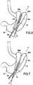
- la
figure1 est une vue en perspective de l'instrument en position ouverte ; - la
figure2 est une vue de détail de l'extrémité distale de l'instrument en position fermée ; - la
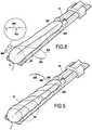
figure3 est une vue éclatée de l'instrument selon l'invention ; - la
figure3A est une vue en coupe longitudinale d'une des encoches de l'un des bras ; - la
figure4 illustre de manière schématique l'estomac d'un patient ; - la
figure5 représente l'étape de plicature lors de laquelle se forment deux bourrelets; - la
figure6 représente le début de l'étape de suture réalisée après que les bourrelets ont été amenés l'un contre l'autre grâce à l'instrument de lafigure1 ; - la
figure7 illustre la fin de l'étape de suture ; et - les
figures8 et9 illustrent en détail le système selon l'invention et la réalisation du surjet à l'aide du fil cranté.
- the
figure1 is a perspective view of the instrument in the open position; - the
figure2 is a detail view of the distal end of the instrument in the closed position; - the
figure3 is an exploded view of the instrument according to the invention; - the
figure3A is a longitudinal sectional view of one of the notches of one of the arms; - the
figure4 schematically illustrates the stomach of a patient; - the
figure5 represents the plication stage during which two beads form; - the
figure6 represents the beginning of the suture step performed after the beads have been brought against each other by the instrument of thefigure1 ; - the
figure7 illustrates the end of the suture step; and - the
Figures8 and9 illustrate in detail the system according to the invention and the production of the overlock using the notched wire.
A l'aide des
Comme on le constate sur la
L'instrument10 comporte un corps12 qui présente une extrémité distale12a et une extrémité proximale12b. On constate que l'extrémité proximale10b de l'instrument10 correspond à l'extrémité proximale12b du corps.The
En outre, le corps est muni, à son extrémité proximale12b, d'un dispositif de préhension14 présentant la forme d'une poignée permettant au chirurgien de saisir fermement l'instrument10.In addition, the body is provided, at its
Dans cet exemple, le corps12 présente la forme d'une tige s'étendant selon une direction longitudinaleA. L'instrument est dimensionné de manière à pouvoir être introduit dans le corps du patient par voie laparoscopique.In this example, the
Lorsque ledit instrument est destiné à être réutilisé pour plusieurs interventions chirurgicales, l'instrument est préférentiellement, mais pas exclusivement, réalisé dans un alliage métallique. Il peut s'agir par exemple, d'un alliage ASI 302 , un ASI 303, un ASI 304, un ASI 410, un ASI 416, un ASI 420, ou l'ASI 440, où ASI correspond à la classification de l'American Iron and Steel Institute (A.S.I.).When said instrument is intended to be reused for several surgical procedures, the instrument is preferably, but not exclusively, made of a metal alloy. It can be, for example, an alloy ASI 302, an ASI 303, an ASI 304, an ASI 410, an ASI 416, an ASI 420, or ASI 440, where ASI corresponds to the classification of the American Iron and Steel Institute (ASI).
Lorsque l'instrument doit être jeté après son utilisation, il peut être réalisé dans une matière plastique très rigide comme par exemple le polymère renforcé de référence IXEF1032 (marque déposée) de la société Solvay. Le IXEF1032 (marque déposée) est un polyarylamide renforcé de 60% de fibre de verre qui a un module de flexion élevé de l'ordre de 21GPa (réalisé selon l'ISO 178). Il peut aussi être réalisé avec le IXEF3008 (marque déposée) qui est un polyarylamide renforcé de 30% de fibre de carbone et qui possède un module de flexion de l'ordre de 23 GPa (réalisé selon l'ISO 178).When the instrument must be discarded after its use, it may be made of a very rigid plastic material, such as, for example, the reference polymer IXEF1032 (trademark) of Solvay. IXEF1032 (trademark) is a 60% glass fiber reinforced polyarylamide which has a high flexural modulus of the order of 21GPa (according to ISO 178). It can also be achieved with the IXEF3008 (registered trademark) which is a polyarylamide reinforced with 30% carbon fiber and which has a flexural modulus of the order of 23 GPa (made according to ISO 178).
A l'extrémité opposée du dispositif de préhension14, l'instrument10 comporte un dispositif de serrage16 qui comporte un premier bras18 et un second bras20 montés pivotants l'un par rapport à l'autre à l'extrémité distale12a du corps12.At the opposite end of the
Comme on le constate sur la
Pour réaliser la liaison pivot (autour de l'axe de rotationB) des premier et second bras18,20 par rapport au corps12, l'instrument10 comporte dans cet exemple une pièce de liaison22 qui est fixée solidairement à l'extrémité distale12a du corps12. Dans l'exemple de la
L'instrument10 comporte en outre un dispositif d'ouverture30 qui a pour fonction d'écarter les premier et second bras18,20 l'un de l'autre en les faisant pivoter l'un par rapport à l'autre autour de l'axeB. Dans cet exemple, le dispositif d'ouverture30 comporte un organe ressort32 qui relie les premier et second bras18,20 en tendant à les maintenir écartés l'un de l'autre. Comme on le voit sur la
L'instrument10 comporte en outre un dispositif de fermeture40 qui a pour fonction de rapprocher les premier et second bras18,20 l'un de l'autre en les faisant pivoter l'un par rapport à l'autre autour de l'axeB.The
Dans cet exemple, le dispositif de fermeture40 comporte un bras d'actionnement42 présentant une extrémité distale42a et une extrémité proximale42b. Le bras d'actionnement42 se présente sous la forme d'une tige dont l'extrémité proximale42b comprend un organe de préhension44 sous forme d'un renvoi orthogonal. La tige42 s'étend selon la direction longitudinaleA du corps12.In this example, the
Le dispositif de fermeture comprend un organe de fermeture 44 fixé à l'extrémité distale42a du bras d'actionnement42. Cet organe de fermeture44 se présente sous la forme d'un manchon. Comme on le constate sur les
Plus spécifiquement, l'organe de fermeture44 en forme de manchon flanque les premier et second bras18,20 de telle sorte que le déplacement du bras d'actionnement42 vers l'extrémité distale10a de l'instrument10 entraîne le rapprochement des premier et second bras18,20 l'un de l'autre. En d'autres termes, comme cela est illustré sur la
On comprend donc que l'organe de fermeture44 est monté coulissant le long des portions18c,20c des premier et second bras18,20, qui sont disposées à proximité de l'extrémité distale12a du corps12.It is thus clear that the
Pour ce faire, l'organe de fermeture44 est monté sur le corps12 de manière coulissante parallèlement à la direction longitudinaleA dudit corps.To do this, the
Ce montage coulissant est obtenu grâce au fait que le bras d'actionnement42 coopère avec un dispositif de guidage50 qui est monté sur le corps afin de permettre au bras d'actionnement de pouvoir coulisser selon la direction longitudinaleA du corps. Dans cet exemple, le dispositif de guidage50 est constitué de deux nervures52,54 s'étendant parallèlement à la direction longitudinale du corps tout en faisant saillie depuis la portion supérieure22a de la pièce de liaison22. Le dispositif de guidage50 forme ainsi une glissière dans laquelle coulisse le bras d'actionnement42.This sliding assembly is obtained thanks to the fact that the
En se référant à la
En se référant à nouveau aux
Compte-tenu de ce qui précède, on comprend que l'instrument10 présente une position ouverte, illustrée sur la
En se référant à la
Lorsque l'organe de fermeture44 est déplacé vers l'extrémité proximale10b de l'instrument10 de manière à venir au contact de la pièce de liaison22, l'organe de fermeture44 libère le pivotement des premier et second bras18,20, en sorte que l'organe ressort écarte les bras l'un de l'autre. En d'autres termes, dans cette position déverrouillée du dispositif de fermeture, l'instrument est libre d'être amené en position ouverte grâce au dispositif d'ouverture30.When the closing
En se référant de nouveau à la
Comme on le verra ci-dessous, ces guides en forme d'encoches sont agencés pour permettre le passage d'une aiguille à suture.As will be seen below, these notched guides are arranged to allow passage of a suture needle.
En se référant à la
En se référant à la
Selon un autre aspect de l'invention, chacun des premier et second bras comporte une portion d'accroche70 s'étendant selon la face latérale intérieure18e,20e des bras. Dans cet exemple, la portion d'accroche70 comprend une pluralité de picots72 qui s'étendent le long des faces latérales intérieures des premier et second bras. Ces picots72 font saillie depuis les faces latérales intérieures18e,20e des bras, de manière à venir s'accrocher avec les tissus. Les bras comportent par ailleurs des orifices74 qui s'étendent également selon des faces latérales intérieures des bras, ces orifices74 étant destinés à recevoir les picots72 lorsque les premier et second bras sont amenés l'un contre l'autre en position fermée de l'instrument10.According to another aspect of the invention, each of the first and second arms comprises a
A l'aide des
Selon une première étape, on saisit une portion du fundusE1 de l'estomac, par exemple à l'aide d'une pince de célioscopie100. La portion du fundus qui a été saisie est amenée, à l'aide de la pince100, vers le fond de l'estomac ce qui a pour effet de former deux bourrelets200,202 qui s'étendent sensiblement selon la grande courbureE3 de l'estomacE. La réalisation de cette plicature est illustrée sur la
Ensuite, tout en maintenant la plicature à l'aide de la pince de célioscopie100, on rapproche les deux bourrelets200,202 l'un de l'autre à l'aide de l'instrument10 selon l'invention. Pour ce faire, on commence par approcher les parties supérieures200a,200b des bourrelets200,202 qui sont disposés à proximité du fundus de l'estomac. L'instrument10 est amené en position ouverte à proximité du fond de l'estomac, les premier et second bras18,20 étant disposés de part et d'autre des bourrelets200 et202. Puis on actionne le dispositif de fermeture de manière à rapprocher les premier et second bras l'un de l'autre, ce qui a pour effet d'amener l'instrument en position fermée. Puis on réalise un premier surjetS1 à l'aide d'une aiguille à suture300 et un fil de suture302. Le surjet est réalisé en faisant passer successivement l'aiguille300 dans les encoches60 des premier et second bras de manière à traverser les deux bourrelets ; ainsi que dans une boucle d'extrémité404 du fil400 jusqu'à former le premier surjetS1, comme illustré sur la
Le fil400 est cranté. Il comprend sur sa surface extérieure des harpons402 qui permettent avantageusement de maintenir le fil de suture serré.The
Après que le premier surjetS1 a été réalisé, l'instrument10 est déplacé vers le fond de l'estomac puis actionné de manière à rapprocher les parties médianes des deux bourrelets200,202 l'une de l'autre. On réalise ensuite un deuxième surjetS2. Puis l'instrument10 est à nouveau déplacé et actionné de manière à rapprocher les parties supérieures des bourrelets200,202 à la suite de quoi on réalise un troisième surjetS3.After the first sutureS1 has been made, the
Bien évidemment, sans sortir du cadre cet exemple on pourrait réaliser un nombre de surjet supérieur à trois.Of course, without departing from the framework this example could achieve a number of overlock greater than three.
Après que les bourrelets ont été suturés grâce aux trois surjets, l'instrument10 et la pince coelioscopie sont retirés. La mise en oeuvre de ce procédé de modification du volume de l'estomac peut être réalisée très rapidement, en moins d'une heure par un chirurgien expérimenté.After the beads have been sutured by the three sures, the
Par ailleurs, les
Claims (15)
- An instrument (10) intended to be used to modify the volume of the stomach of a patient, said instrument having a distal end (10a) and comprising:a body (12) having a distal end (12a);a clamping device (16) comprising first (18) and second (20) arms pivotably mounted at the distal end (12a) of the body (12) while pivoting relative to each other, each of the first and second arms (18, 20) comprising a plurality of guides for passage of a suture needle;an opening device (30) for moving the first and second arms (18, 20) apart from each other by having them pivot relative to each other, said opening device comprising a spring member (32) connecting the first and second arms (18, 20) and tending to keep them apart from each other; anda closing device (40) for moving the first and second arms (18, 20) towards each other by having them pivot relative to each other.
- The instrument according to claim 1, having an open position wherein the first and second arms (18, 20) are moved apart from each other because of the opening device (30), and a closed position wherein the first and second arms (18, 20) are brought towards each other because of the closing device (40), and the closing device (40) having a locked position wherein the instrument (10) is kept in a closed position, and an unlocked position wherein the instrument is free to be guided to the open position by the opening device (30).
- The instrument according to any one of claims 1 to 2, wherein each of the first (18) and second (20) arm has an end (18b, 20b) pivotably attached at the distal end of the body.
- The instrument according to claim 3, wherein the ends (18b, 20b) of the first and second arms (18, 20) pivotably attached at the distal end (12a) of the body (12) are pivotably mounted about the same axis of rotation (13).
- The instrument according to any one of claims 1 to 4, wherein the closing device (40) comprises an actuatable closing member (44) cooperating with the first and second arms (18, 20) such that the actuation of the closing member by the surgeon causes the first and second arms to move towards each other.
- The instrument according to claim 5, wherein the body (12) has a longitudinal direction (A), and wherein the closing member (44) is slidably mounted on the body (12) parallel to said longitudinal direction.
- The instrument according to claim 6, wherein the closing device comprises an actuating arm (42) which cooperates with a guide device (56) mounted on the body allowing the actuating arm to slide along the longitudinal direction (A) of the body, wherein the closing member (44) is arranged at a distal end (42a) of the actuating arm (42) and flanks the first and second arms (18, 20) such that displacement of the actuating arm (42) towards the distal end (10a) of the instrument (10) causes the first and second arms to move towards each other.
- The instrument according to claim 6 or 7, further comprising at least one stop member (56, 58) configured to limit displacement of the closing member (44) towards the distal end (10a) of the instrument (10).
- The instrument according to claim 8, wherein the stop member (56, 58) projects from one of the first and second arms (18, 20).
- The instrument according to any one of claims 1 to 9, wherein at least the first arm (18) comprises a hooking portion (70) extending according to an inner lateral face (18e) of the first arm arranged facing an inner lateral face (20e) of the second arm (20).
- The instrument according to claim 10, wherein the hooking portion comprises a plurality of barbs (72) extending along the inner lateral face of the first arm.
- The instrument according to claim 11, wherein at least the second arm (20) comprises orifices (74) extending along the inner lateral face of the second arm facing the inner lateral face of the first arm, said orifices (74) being intended to receive the barbs (72) of the first arm when the first and second arms are brought against each other.
- The instrument according to any one of claims 1 to 12, wherein the guides (60) terminate transversally on either side of each of the first and second arms.
- The instrument according to claim 13, wherein the first and second arms (18, 20) have upper faces (18d, 20d), and wherein the guides are slots terminating in the upper faces of the first and second arms, and wherein the cross-section of the slots (60) has a divergent shape opening towards the upper faces (18d, 20d).
- A system (S) intended to be used to modify the volume of the stomach (E) of a patient, comprising an instrument (10) according to any one of claims 1 to 14, a suture needle (300), and at least one notched suture thread (400) whereof the notches form harpoons.
Applications Claiming Priority (2)
| Application Number | Priority Date | Filing Date | Title |
|---|---|---|---|
| FR1354507AFR3005564B1 (en) | 2013-05-20 | 2013-05-20 | INSTRUMENT FOR USE IN MODIFYING THE VOLUME OF THE STOMACH OF A PATIENT. |
| PCT/FR2014/051171WO2014188114A1 (en) | 2013-05-20 | 2014-05-20 | Instrument intended to be used to modify the volume of the stomach of a patient |
Publications (2)
| Publication Number | Publication Date |
|---|---|
| EP2999416A1 EP2999416A1 (en) | 2016-03-30 |
| EP2999416B1true EP2999416B1 (en) | 2017-03-15 |
Family
ID=49111367
Family Applications (1)
| Application Number | Title | Priority Date | Filing Date |
|---|---|---|---|
| EP14731693.9ANot-in-forceEP2999416B1 (en) | 2013-05-20 | 2014-05-20 | Instrument intended to be used to modify the volume of the stomach of a patient |
Country Status (5)
| Country | Link |
|---|---|
| US (1) | US20160081833A1 (en) |
| EP (1) | EP2999416B1 (en) |
| ES (1) | ES2628131T3 (en) |
| FR (1) | FR3005564B1 (en) |
| WO (1) | WO2014188114A1 (en) |
Families Citing this family (18)
| Publication number | Priority date | Publication date | Assignee | Title |
|---|---|---|---|---|
| US9913577B2 (en) | 2010-09-28 | 2018-03-13 | Obp Medical Corporation | Speculum |
| US9867602B2 (en) | 2015-02-05 | 2018-01-16 | Obp Medical Corporation | Illuminated surgical retractor |
| US10420538B2 (en) | 2015-02-05 | 2019-09-24 | Obp Medical Corporation | Illuminated surgical retractor |
| ES2968069T3 (en) | 2015-06-03 | 2024-05-07 | Obp Surgical Corp | Retractor |
| US10881387B2 (en)* | 2015-06-03 | 2021-01-05 | Obp Medical Corporation | Retractor |
| US10939899B2 (en) | 2015-06-03 | 2021-03-09 | Obp Medical Corporation | End cap assembly for retractor and other medical devices |
| US20170150878A1 (en)* | 2015-11-30 | 2017-06-01 | Obp Corporation | Laryngoscope |
| ES1158811Y (en)* | 2016-05-12 | 2016-09-09 | Ansabere Surgical S L | CLAMP FOR MEDICAL USE |
| US10722621B2 (en) | 2016-07-11 | 2020-07-28 | Obp Medical Corporation | Illuminated suction device |
| US20180021100A1 (en)* | 2016-07-19 | 2018-01-25 | Obp Medical Corporation | Surgical retractor |
| US10687793B2 (en) | 2017-07-18 | 2020-06-23 | Obp Medical Corporation | Minimally invasive no touch (MINT) procedure for harvesting the great saphenous vein (GSV) and venous hydrodissector and retractor for use during the MINT procedure |
| US10278572B1 (en) | 2017-10-19 | 2019-05-07 | Obp Medical Corporation | Speculum |
| US10799229B2 (en) | 2018-02-20 | 2020-10-13 | Obp Medical Corporation | Illuminated medical devices |
| USD911521S1 (en) | 2019-02-19 | 2021-02-23 | Obp Medical Corporation | Handle for medical devices including surgical retractors |
| USD904607S1 (en) | 2019-05-07 | 2020-12-08 | Obp Medical Corporation | Nasal retractor |
| US10959609B1 (en) | 2020-01-31 | 2021-03-30 | Obp Medical Corporation | Illuminated suction device |
| US10966702B1 (en) | 2020-02-25 | 2021-04-06 | Obp Medical Corporation | Illuminated dual-blade retractor |
| US12318080B2 (en) | 2023-07-21 | 2025-06-03 | Coopersurgical, Inc. | Illuminated surgical retractor capable of hand-held operation and of being mounted to a fixed frame |
Family Cites Families (18)
| Publication number | Priority date | Publication date | Assignee | Title |
|---|---|---|---|---|
| US5549621A (en) | 1993-05-14 | 1996-08-27 | Byron C. Sutherland | Apparatus and method for performing vertical banded gastroplasty |
| US5534008A (en)* | 1994-09-28 | 1996-07-09 | Acksel; Ione | Suturing guide and clamp |
| DE19964081B4 (en)* | 1999-12-29 | 2005-06-30 | Ethicon Gmbh | Stripe-type implant and surgical gripping instrument |
| ES2174749B1 (en) | 2001-02-12 | 2004-08-16 | Luis Miguel Molina Trigueros | GASTRIC CLAMP FOR THE CONDUCT OF VERTICAL GASTROPLASTIA BANDEADA AND BY-PASS GASTRIC TO MINOR CURVING. |
| US6547797B1 (en)* | 2001-07-11 | 2003-04-15 | Sang Bong Lee | Circumcision clamp |
| US6773440B2 (en)* | 2002-07-02 | 2004-08-10 | Satiety, Inc. | Method and device for use in tissue approximation and fixation |
| US10548592B2 (en)* | 2004-05-14 | 2020-02-04 | Ethicon, Inc. | Suture methods and devices |
| US20080172085A1 (en)* | 2007-01-16 | 2008-07-17 | Kwok Wai Chiu | Elliptical Excision Clamp |
| US20080208324A1 (en)* | 2007-02-23 | 2008-08-28 | Glithero Jason I | Method and apparatus for occluding an anatomical structure |
| US8979872B2 (en) | 2007-03-13 | 2015-03-17 | Longevity Surgical, Inc. | Devices for engaging, approximating and fastening tissue |
| US20100082046A1 (en)* | 2007-07-18 | 2010-04-01 | Harris Jason L | Device For Deploying A Fastener For Use in a Gastric Volume Reduction Procedure |
| US20090209986A1 (en)* | 2008-02-15 | 2009-08-20 | Stewart Michael C | Devices, Tools and Methods for Atrial Appendage Exclusion |
| US8597310B2 (en)* | 2009-01-09 | 2013-12-03 | Cook Medical Technologies Llc | Laparoscopic anastomosis tools and technique |
| US20120330329A1 (en) | 2011-06-21 | 2012-12-27 | Harris Jason L | Methods of forming a laparoscopic greater curvature plication using a surgical stapler |
| US20110098725A1 (en)* | 2009-09-03 | 2011-04-28 | Usgi Medical, Inc. | Devices and methods for endolumenal weight loss treatments |
| US8647350B2 (en)* | 2009-08-11 | 2014-02-11 | Raptor Ridge, Llc | Delivery device and method for compliant tissue fasteners |
| WO2011094700A1 (en)* | 2010-01-29 | 2011-08-04 | Advanced Bariatric Technology, Llc | Surgical clamp and surgical clamp installation tool |
| US8382775B1 (en)* | 2012-01-08 | 2013-02-26 | Vibrynt, Inc. | Methods, instruments and devices for extragastric reduction of stomach volume |
- 2013
- 2013-05-20FRFR1354507Apatent/FR3005564B1/enactiveActive
- 2014
- 2014-05-20WOPCT/FR2014/051171patent/WO2014188114A1/enactiveApplication Filing
- 2014-05-20EPEP14731693.9Apatent/EP2999416B1/ennot_activeNot-in-force
- 2014-05-20USUS14/892,259patent/US20160081833A1/ennot_activeAbandoned
- 2014-05-20ESES14731693.9Tpatent/ES2628131T3/enactiveActive
Non-Patent Citations (1)
| Title |
|---|
| None* |
Also Published As
| Publication number | Publication date |
|---|---|
| WO2014188114A1 (en) | 2014-11-27 |
| ES2628131T3 (en) | 2017-08-01 |
| EP2999416A1 (en) | 2016-03-30 |
| FR3005564A1 (en) | 2014-11-21 |
| FR3005564B1 (en) | 2018-01-12 |
| US20160081833A1 (en) | 2016-03-24 |
Similar Documents
| Publication | Publication Date | Title |
|---|---|---|
| EP2999416B1 (en) | Instrument intended to be used to modify the volume of the stomach of a patient | |
| EP2345377B1 (en) | Device for ligating an anatomical structure | |
| FR2470606A1 (en) | IMPROVED VEIN PERFORATION DEVICE | |
| EP0369324B1 (en) | Surgical instrument | |
| EP2725993B1 (en) | Vertebral fixation device | |
| FR2850857A1 (en) | Compact suture punch for passing braided suture through tissue has needle deformed causing it and suture material from entering into and exiting from tissue when end of tube is set proximate tissue to be sutured | |
| FR2586553A1 (en) | SURGICAL SUTURE APPARATUS | |
| FR2508791A1 (en) | INSTRUMENT FOR THE MANUFACTURE OF TWO-BRANCH SUTURES USED IN SURGERY | |
| EP3256055B1 (en) | Surgical staple having two movable arms connected by a transverse connection area | |
| FR2868283A1 (en) | COMPACT SWITCHING PLIERS WITH MALLEABLE NEEDLE | |
| FR2704132A1 (en) | System for ligature and / or suture for endoscopic surgery. | |
| EP2391283B1 (en) | Microsurgery clamp, in particular microincision capsulorhexis clamp | |
| FR2640131A1 (en) | LIGATURE ASSEMBLY FOR ENDOSCOPIC SURGERY, LIGATURE AND LIGATURE HANDLING INSTRUMENT THEREFOR | |
| FR2906995A1 (en) | MULTI-NEEDLE SURGICAL HANDWOOD FOR HOLLOW MEMBER AND CORRESPONDING SYSTEM | |
| FR3006582A1 (en) | DEVICE FOR TREATING A BODY TISSUE AND NECESSARY TREATMENT THEREFOR | |
| EP1895917B1 (en) | Ophthalmologic microsurgical forceps for single use | |
| WO2022171801A1 (en) | Device for locking suture threads | |
| EP3256056B1 (en) | Endoscopic surgery system consisting of a plurality of staples and an endoscopic applicator | |
| EP3509503B1 (en) | Endoscopic needle carrier | |
| WO2000057802A1 (en) | Bipolar forceps for conducting a pelviscopy | |
| FR2941868A1 (en) | SECURE NEEDLE DEVICE, IN PARTICULAR HUBER NEEDLE | |
| WO2011145078A1 (en) | Surgical forceps for phlebectomy | |
| FR2657247A1 (en) | NEEDLE TO SUTURE. | |
| EP4444192B1 (en) | Endoscopic gastric plication device | |
| EP2335880A2 (en) | Diagonal cutting nippers for cable tie |
Legal Events
| Date | Code | Title | Description |
|---|---|---|---|
| PUAI | Public reference made under article 153(3) epc to a published international application that has entered the european phase | Free format text:ORIGINAL CODE: 0009012 | |
| 17P | Request for examination filed | Effective date:20151118 | |
| AK | Designated contracting states | Kind code of ref document:A1 Designated state(s):AL AT BE BG CH CY CZ DE DK EE ES FI FR GB GR HR HU IE IS IT LI LT LU LV MC MK MT NL NO PL PT RO RS SE SI SK SM TR | |
| AX | Request for extension of the european patent | Extension state:BA ME | |
| DAX | Request for extension of the european patent (deleted) | ||
| GRAP | Despatch of communication of intention to grant a patent | Free format text:ORIGINAL CODE: EPIDOSNIGR1 | |
| INTG | Intention to grant announced | Effective date:20161005 | |
| GRAS | Grant fee paid | Free format text:ORIGINAL CODE: EPIDOSNIGR3 | |
| GRAA | (expected) grant | Free format text:ORIGINAL CODE: 0009210 | |
| AK | Designated contracting states | Kind code of ref document:B1 Designated state(s):AL AT BE BG CH CY CZ DE DK EE ES FI FR GB GR HR HU IE IS IT LI LT LU LV MC MK MT NL NO PL PT RO RS SE SI SK SM TR | |
| REG | Reference to a national code | Ref country code:CH Ref legal event code:EP Ref country code:GB Ref legal event code:FG4D Free format text:NOT ENGLISH | |
| REG | Reference to a national code | Ref country code:IE Ref legal event code:FG4D Free format text:LANGUAGE OF EP DOCUMENT: FRENCH | |
| REG | Reference to a national code | Ref country code:AT Ref legal event code:REF Ref document number:874756 Country of ref document:AT Kind code of ref document:T Effective date:20170415 | |
| REG | Reference to a national code | Ref country code:DE Ref legal event code:R096 Ref document number:602014007660 Country of ref document:DE | |
| REG | Reference to a national code | Ref country code:FR Ref legal event code:PLFP Year of fee payment:4 | |
| REG | Reference to a national code | Ref country code:NL Ref legal event code:MP Effective date:20170315 | |
| REG | Reference to a national code | Ref country code:LT Ref legal event code:MG4D | |
| PG25 | Lapsed in a contracting state [announced via postgrant information from national office to epo] | Ref country code:LT Free format text:LAPSE BECAUSE OF FAILURE TO SUBMIT A TRANSLATION OF THE DESCRIPTION OR TO PAY THE FEE WITHIN THE PRESCRIBED TIME-LIMIT Effective date:20170315 Ref country code:FI Free format text:LAPSE BECAUSE OF FAILURE TO SUBMIT A TRANSLATION OF THE DESCRIPTION OR TO PAY THE FEE WITHIN THE PRESCRIBED TIME-LIMIT Effective date:20170315 Ref country code:HR Free format text:LAPSE BECAUSE OF FAILURE TO SUBMIT A TRANSLATION OF THE DESCRIPTION OR TO PAY THE FEE WITHIN THE PRESCRIBED TIME-LIMIT Effective date:20170315 Ref country code:NO Free format text:LAPSE BECAUSE OF FAILURE TO SUBMIT A TRANSLATION OF THE DESCRIPTION OR TO PAY THE FEE WITHIN THE PRESCRIBED TIME-LIMIT Effective date:20170615 Ref country code:GR Free format text:LAPSE BECAUSE OF FAILURE TO SUBMIT A TRANSLATION OF THE DESCRIPTION OR TO PAY THE FEE WITHIN THE PRESCRIBED TIME-LIMIT Effective date:20170616 | |
| REG | Reference to a national code | Ref country code:ES Ref legal event code:FG2A Ref document number:2628131 Country of ref document:ES Kind code of ref document:T3 Effective date:20170801 | |
| REG | Reference to a national code | Ref country code:AT Ref legal event code:MK05 Ref document number:874756 Country of ref document:AT Kind code of ref document:T Effective date:20170315 | |
| PG25 | Lapsed in a contracting state [announced via postgrant information from national office to epo] | Ref country code:LV Free format text:LAPSE BECAUSE OF FAILURE TO SUBMIT A TRANSLATION OF THE DESCRIPTION OR TO PAY THE FEE WITHIN THE PRESCRIBED TIME-LIMIT Effective date:20170315 Ref country code:LU Free format text:LAPSE BECAUSE OF NON-PAYMENT OF DUE FEES Effective date:20170531 Ref country code:SE Free format text:LAPSE BECAUSE OF FAILURE TO SUBMIT A TRANSLATION OF THE DESCRIPTION OR TO PAY THE FEE WITHIN THE PRESCRIBED TIME-LIMIT Effective date:20170315 Ref country code:RS Free format text:LAPSE BECAUSE OF FAILURE TO SUBMIT A TRANSLATION OF THE DESCRIPTION OR TO PAY THE FEE WITHIN THE PRESCRIBED TIME-LIMIT Effective date:20170315 Ref country code:BG Free format text:LAPSE BECAUSE OF FAILURE TO SUBMIT A TRANSLATION OF THE DESCRIPTION OR TO PAY THE FEE WITHIN THE PRESCRIBED TIME-LIMIT Effective date:20170615 | |
| PG25 | Lapsed in a contracting state [announced via postgrant information from national office to epo] | Ref country code:NL Free format text:LAPSE BECAUSE OF FAILURE TO SUBMIT A TRANSLATION OF THE DESCRIPTION OR TO PAY THE FEE WITHIN THE PRESCRIBED TIME-LIMIT Effective date:20170315 | |
| PG25 | Lapsed in a contracting state [announced via postgrant information from national office to epo] | Ref country code:EE Free format text:LAPSE BECAUSE OF FAILURE TO SUBMIT A TRANSLATION OF THE DESCRIPTION OR TO PAY THE FEE WITHIN THE PRESCRIBED TIME-LIMIT Effective date:20170315 Ref country code:SK Free format text:LAPSE BECAUSE OF FAILURE TO SUBMIT A TRANSLATION OF THE DESCRIPTION OR TO PAY THE FEE WITHIN THE PRESCRIBED TIME-LIMIT Effective date:20170315 Ref country code:CZ Free format text:LAPSE BECAUSE OF FAILURE TO SUBMIT A TRANSLATION OF THE DESCRIPTION OR TO PAY THE FEE WITHIN THE PRESCRIBED TIME-LIMIT Effective date:20170315 Ref country code:RO Free format text:LAPSE BECAUSE OF FAILURE TO SUBMIT A TRANSLATION OF THE DESCRIPTION OR TO PAY THE FEE WITHIN THE PRESCRIBED TIME-LIMIT Effective date:20170315 Ref country code:AT Free format text:LAPSE BECAUSE OF FAILURE TO SUBMIT A TRANSLATION OF THE DESCRIPTION OR TO PAY THE FEE WITHIN THE PRESCRIBED TIME-LIMIT Effective date:20170315 | |
| PG25 | Lapsed in a contracting state [announced via postgrant information from national office to epo] | Ref country code:PL Free format text:LAPSE BECAUSE OF FAILURE TO SUBMIT A TRANSLATION OF THE DESCRIPTION OR TO PAY THE FEE WITHIN THE PRESCRIBED TIME-LIMIT Effective date:20170315 Ref country code:IS Free format text:LAPSE BECAUSE OF FAILURE TO SUBMIT A TRANSLATION OF THE DESCRIPTION OR TO PAY THE FEE WITHIN THE PRESCRIBED TIME-LIMIT Effective date:20170715 Ref country code:PT Free format text:LAPSE BECAUSE OF FAILURE TO SUBMIT A TRANSLATION OF THE DESCRIPTION OR TO PAY THE FEE WITHIN THE PRESCRIBED TIME-LIMIT Effective date:20170717 Ref country code:SM Free format text:LAPSE BECAUSE OF FAILURE TO SUBMIT A TRANSLATION OF THE DESCRIPTION OR TO PAY THE FEE WITHIN THE PRESCRIBED TIME-LIMIT Effective date:20170315 | |
| REG | Reference to a national code | Ref country code:DE Ref legal event code:R097 Ref document number:602014007660 Country of ref document:DE | |
| REG | Reference to a national code | Ref country code:CH Ref legal event code:PL | |
| PLBE | No opposition filed within time limit | Free format text:ORIGINAL CODE: 0009261 | |
| STAA | Information on the status of an ep patent application or granted ep patent | Free format text:STATUS: NO OPPOSITION FILED WITHIN TIME LIMIT | |
| PG25 | Lapsed in a contracting state [announced via postgrant information from national office to epo] | Ref country code:MC Free format text:LAPSE BECAUSE OF FAILURE TO SUBMIT A TRANSLATION OF THE DESCRIPTION OR TO PAY THE FEE WITHIN THE PRESCRIBED TIME-LIMIT Effective date:20170315 Ref country code:DK Free format text:LAPSE BECAUSE OF FAILURE TO SUBMIT A TRANSLATION OF THE DESCRIPTION OR TO PAY THE FEE WITHIN THE PRESCRIBED TIME-LIMIT Effective date:20170315 | |
| REG | Reference to a national code | Ref country code:FR Ref legal event code:PLFP Year of fee payment:5 | |
| 26N | No opposition filed | Effective date:20171218 | |
| REG | Reference to a national code | Ref country code:IE Ref legal event code:MM4A | |
| PG25 | Lapsed in a contracting state [announced via postgrant information from national office to epo] | Ref country code:SI Free format text:LAPSE BECAUSE OF FAILURE TO SUBMIT A TRANSLATION OF THE DESCRIPTION OR TO PAY THE FEE WITHIN THE PRESCRIBED TIME-LIMIT Effective date:20170315 Ref country code:LI Free format text:LAPSE BECAUSE OF NON-PAYMENT OF DUE FEES Effective date:20170531 Ref country code:CH Free format text:LAPSE BECAUSE OF NON-PAYMENT OF DUE FEES Effective date:20170531 | |
| PG25 | Lapsed in a contracting state [announced via postgrant information from national office to epo] | Ref country code:LU Free format text:LAPSE BECAUSE OF NON-PAYMENT OF DUE FEES Effective date:20170520 | |
| REG | Reference to a national code | Ref country code:BE Ref legal event code:MM Effective date:20170531 | |
| PG25 | Lapsed in a contracting state [announced via postgrant information from national office to epo] | Ref country code:IE Free format text:LAPSE BECAUSE OF NON-PAYMENT OF DUE FEES Effective date:20170520 | |
| PG25 | Lapsed in a contracting state [announced via postgrant information from national office to epo] | Ref country code:BE Free format text:LAPSE BECAUSE OF NON-PAYMENT OF DUE FEES Effective date:20170531 | |
| PG25 | Lapsed in a contracting state [announced via postgrant information from national office to epo] | Ref country code:MT Free format text:LAPSE BECAUSE OF FAILURE TO SUBMIT A TRANSLATION OF THE DESCRIPTION OR TO PAY THE FEE WITHIN THE PRESCRIBED TIME-LIMIT Effective date:20170315 | |
| PG25 | Lapsed in a contracting state [announced via postgrant information from national office to epo] | Ref country code:HU Free format text:LAPSE BECAUSE OF FAILURE TO SUBMIT A TRANSLATION OF THE DESCRIPTION OR TO PAY THE FEE WITHIN THE PRESCRIBED TIME-LIMIT; INVALID AB INITIO Effective date:20140520 | |
| PGFP | Annual fee paid to national office [announced via postgrant information from national office to epo] | Ref country code:DE Payment date:20190510 Year of fee payment:6 Ref country code:IT Payment date:20190522 Year of fee payment:6 Ref country code:ES Payment date:20190606 Year of fee payment:6 | |
| PGFP | Annual fee paid to national office [announced via postgrant information from national office to epo] | Ref country code:FR Payment date:20190520 Year of fee payment:6 | |
| PG25 | Lapsed in a contracting state [announced via postgrant information from national office to epo] | Ref country code:CY Free format text:LAPSE BECAUSE OF FAILURE TO SUBMIT A TRANSLATION OF THE DESCRIPTION OR TO PAY THE FEE WITHIN THE PRESCRIBED TIME-LIMIT Effective date:20170315 | |
| PGFP | Annual fee paid to national office [announced via postgrant information from national office to epo] | Ref country code:GB Payment date:20190516 Year of fee payment:6 | |
| PG25 | Lapsed in a contracting state [announced via postgrant information from national office to epo] | Ref country code:MK Free format text:LAPSE BECAUSE OF FAILURE TO SUBMIT A TRANSLATION OF THE DESCRIPTION OR TO PAY THE FEE WITHIN THE PRESCRIBED TIME-LIMIT Effective date:20170315 | |
| PG25 | Lapsed in a contracting state [announced via postgrant information from national office to epo] | Ref country code:TR Free format text:LAPSE BECAUSE OF FAILURE TO SUBMIT A TRANSLATION OF THE DESCRIPTION OR TO PAY THE FEE WITHIN THE PRESCRIBED TIME-LIMIT Effective date:20170315 | |
| PG25 | Lapsed in a contracting state [announced via postgrant information from national office to epo] | Ref country code:AL Free format text:LAPSE BECAUSE OF FAILURE TO SUBMIT A TRANSLATION OF THE DESCRIPTION OR TO PAY THE FEE WITHIN THE PRESCRIBED TIME-LIMIT Effective date:20170315 | |
| REG | Reference to a national code | Ref country code:DE Ref legal event code:R119 Ref document number:602014007660 Country of ref document:DE | |
| GBPC | Gb: european patent ceased through non-payment of renewal fee | Effective date:20200520 | |
| PG25 | Lapsed in a contracting state [announced via postgrant information from national office to epo] | Ref country code:FR Free format text:LAPSE BECAUSE OF NON-PAYMENT OF DUE FEES Effective date:20200531 Ref country code:GB Free format text:LAPSE BECAUSE OF NON-PAYMENT OF DUE FEES Effective date:20200520 | |
| PG25 | Lapsed in a contracting state [announced via postgrant information from national office to epo] | Ref country code:DE Free format text:LAPSE BECAUSE OF NON-PAYMENT OF DUE FEES Effective date:20201201 | |
| REG | Reference to a national code | Ref country code:ES Ref legal event code:FD2A Effective date:20210930 | |
| PG25 | Lapsed in a contracting state [announced via postgrant information from national office to epo] | Ref country code:IT Free format text:LAPSE BECAUSE OF NON-PAYMENT OF DUE FEES Effective date:20200520 | |
| PG25 | Lapsed in a contracting state [announced via postgrant information from national office to epo] | Ref country code:ES Free format text:LAPSE BECAUSE OF NON-PAYMENT OF DUE FEES Effective date:20200521 |