EP2999393B1 - Method for determining ocular measurements using a consumer sensor - Google Patents
Method for determining ocular measurements using a consumer sensorDownload PDFInfo
- Publication number
- EP2999393B1 EP2999393B1EP14741572.3AEP14741572AEP2999393B1EP 2999393 B1EP2999393 B1EP 2999393B1EP 14741572 AEP14741572 AEP 14741572AEP 2999393 B1EP2999393 B1EP 2999393B1
- Authority
- EP
- European Patent Office
- Prior art keywords
- image
- user
- face
- measurement
- une
- Prior art date
- Legal status (The legal status is an assumption and is not a legal conclusion. Google has not performed a legal analysis and makes no representation as to the accuracy of the status listed.)
- Active
Links
Images

Classifications
- A—HUMAN NECESSITIES
- A61—MEDICAL OR VETERINARY SCIENCE; HYGIENE
- A61B—DIAGNOSIS; SURGERY; IDENTIFICATION
- A61B3/00—Apparatus for testing the eyes; Instruments for examining the eyes
- A61B3/10—Objective types, i.e. instruments for examining the eyes independent of the patients' perceptions or reactions
- A61B3/11—Objective types, i.e. instruments for examining the eyes independent of the patients' perceptions or reactions for measuring interpupillary distance or diameter of pupils
- A61B3/111—Objective types, i.e. instruments for examining the eyes independent of the patients' perceptions or reactions for measuring interpupillary distance or diameter of pupils for measuring interpupillary distance
- A—HUMAN NECESSITIES
- A61—MEDICAL OR VETERINARY SCIENCE; HYGIENE
- A61B—DIAGNOSIS; SURGERY; IDENTIFICATION
- A61B3/00—Apparatus for testing the eyes; Instruments for examining the eyes
- A61B3/0016—Operational features thereof
- A61B3/0041—Operational features thereof characterised by display arrangements
- A—HUMAN NECESSITIES
- A61—MEDICAL OR VETERINARY SCIENCE; HYGIENE
- A61B—DIAGNOSIS; SURGERY; IDENTIFICATION
- A61B3/00—Apparatus for testing the eyes; Instruments for examining the eyes
- A61B3/10—Objective types, i.e. instruments for examining the eyes independent of the patients' perceptions or reactions
- A61B3/14—Arrangements specially adapted for eye photography
- A61B3/145—Arrangements specially adapted for eye photography by video means
Definitions
- the inventionrelates to the field of optics. It relates more particularly to the field of the manufacture of corrective lenses for sight.
- the pupillary distance(called PD in the remainder of the description) is the distance between the centers of the pupils when the subject is looking at infinity.
- the single pupil distance(denoted MonoPD in the remainder of the description) is the distance between the projection of the pupil in the plane of the lens and the center of the frame. This quantity measures the horizontal offset to be applied when cutting the lens.
- the heightsare the distances between the projection of the pupils in the plane of the lens and the bottom of the frame (presumed interior of the internal dragee). This quantity measures the vertical offset to be applied when cutting the lens.
- the closest state to the present inventionis represented by document US 6535223 which discloses a standard method of determining pupillary distance and heights and by the WO2012 / 04154995 which describes a method of taking and providing an image of the face.
- the inventionconsists in determining the ocular and optical measurements allowing the manufacture and the precise mounting of corrective lenses on a pair of glasses from an image.
- This patent applicationis a variation of the 3D analysis proposed in the patent FR 10 52001 , on measurements from a single image.
- the process described hereguarantees an accuracy of 0.5mm, achievable with cameras on the market, even of poor quality. It is applicable in an 'internet' context, at home, with everyday tools, and in optical stores.
- the solutions that appear obvious to those skilled in the artare analyzed and their theoretical and practical invalidity is explained.
- test patterncould equally well be an object of known size which is available to the user (credit card for example) or even his own face in 3D reconstructed metrically.
- the inventionthus relates in a first aspect to a method for determining at least one ocular measurement (pupillary distance, single pupillary distance and / or heights) of a user using a digital image sensor, of the general public type.
- the methoduses at least one image of the user's head, acquired by the image sensor, containing an object of known size, and the camera calibration parameters are unknown or known with little precision.
- the measurementis possible in a single image acquisition, or several, unlike the previous methods which are wrong with a single image, or require a large set of images to provide a reliable solution.
- the user's headis placed face-on on at least one image.
- the useris at a known distance from the acquisition device and the object of known size is positioned at a known distance from the zone being the object of the ocular measurement.
- the useris guided by an interactive system to aid in correct positioning.
- the interactive system for assisting in correct positioningis a shape drawn on the display screen (a face shape for example).
- the interactive system for assisting in correct positioningcomprises instructions resulting from real-time monitoring of the user's face.
- the image sensoris then for example of the Kinect -registered- type.
- the ideal targetis a pair of glasses of known size on the face, and of known face-to-eye distance. This test pattern allows an ideal placement in position, and helps a face orientation by symmetrical projection of the visible surface of the branches in the image.
- Another type of target that correspondsis a credit card or a CD, which is preferably placed on the mouth-chin area or on the forehead.
- Another source of erroris the accuracy of the image.
- itis necessary to locate on the image obtained landmarks, which allow the transfer to be carried out.
- the proposed systemsrequire specifying a known length on the target object and the center of the pupils on the eyes. The problem then encountered and not dealt with by the existing systems and the error of pointing and locating these landmarks, which is made by a human most often, or a recognition algorithm, but whose imprecision is such that it is is a greater source of error than the parallax error described above for conventional sensors.
- the system for digitizing the real scene to the final digital imageadds a number of conventional treatments inherent in digital sensors for the general public: quantization, compression [others].
- quantization, compression[others].
- the quality of the sensorsincreases over time, but the quality of the image is not always good due to the combination of several known factors such as the sensitivity of the sensor, the light conditions, the material transfer time of the digital data which imposes size and compression constraints.
- the final imageis often noisy, saturated or lacking in dynamics, which has the effect of limiting the accuracy of the location of landmarks.
- the sensorscan have high resolutions, the compression algorithms bring a lot of imprecision on the contours or hallucinate new ones.
- the outline of a flat objectcan be several pixels wide.
- the subjectmust stand at a known (or estimable) distance from the image acquisition device and look in front of him (a particular point or the acquisition device for example) by placing a rigid object of known size (target) at a known (or estimable) distance from the plane containing the pupils. It is recalled that in in the case where the metric 3D face of the user is known, the planar target is not necessary.
- An image acquisition of the subjectis then carried out when his head is straight in front of the camera (ears and eyes almost aligned). Ideally, the subject's 2 ears should be equally visible.
- a video streamcan be recorded while the user performs a particular head movement to choose the most appropriate image.
- the imagecan also be automatically chosen using 3D face tracking.
- the ideal placement of the rigid objectis located at a fixed or estimable distance (statistically) from the plane containing the pupils, one face of the target object having to be as parallel as possible to this plane containing the pupils.
- the rigid objectmay be on the forehead, on a cheek or on the mouth.
- Dthe distance D expressed in pixels (in the image)
- tMMthe measurable size of the rigid object (pattern) in mm
- tMPthe size of the pattern in pixels on the acquired image (see. figure 1 and figure 2 ).
- the size of the test pattern in pixels on the acquired imagecan then be corrected (the corrected value is denoted by_tMP2 ), this is an estimate of the size that the test object would have if it were in the plane.
- pupilsin the case of calculating PD and monoPD
- glassesin the case of calculating heights:
- tMP2tMP * fe / (dC + p / O).
- pIOthe depth (known, estimated or assumed) between the plane containing the known magnitude of the rigid object (target) and the plane containing the pupils (in the case of the calculation of PD and monoPD ) or the glasses (in the case of the calculation of heights).
- the corrected D measurementis equal to : dP * tMM / tMP2.
- a software allowing the acquisition and the calculationscan take the form of an application and / or a website / plugin for browser. This software can guide the user as to the placement of his camera and his gaze positioning.
- This interfacecan be used by the end user, but is above all intended to be used by a trained expert in order to ensure processing stability.
- the interfaceoffers a global and local approach to the manipulation of the form of SEO.
- a rectangleis presented to the user, of size and positions close to those expected on the image. This rectangle has four control points.
- a global deformation modemakes it possible to manage a deformation in scale and rotation, with a fixed ratio width / height. Normally, the correctly positioned card when carrying out the protocol must present an image that allows the geometric model of the interface to be aligned with the image.
- the zoomed part of the interfacemakes it possible to manage the local uncertainties due to the problems of compression and quantization of the image.
- the second mode of modifying the geometric shape of the mapmakes it possible to modify the position of the points one by one and independently of the others. These points being linked together, the expert user can visualize the line formed between these points and thus follow the outline of the map exactly. The geometric shape then follows the contours of the projective deformation of the image of the real map. If this deformation is too great, this gives an indication of the quality of the protocol. Often, problems with image compression and inadequate quantization occur in areas of low contrast. Thus, the outlines are no longer visible all along the edges. The expert user can then choose the most relevant areas on which to rely. As a black band is present on the back of the card, the contrast can be strong at this level, and the geometric rectangle can be adapted on this band if necessary.
- the distance used for the measurementis the distance located at the top of the strip, which corresponds to the most stable support points of the card on the face, and for which the hypotheses made for the transfer are the most reliable.
- the processis free from parallax and detection errors, and guarantees the right conditions and corrections for accurate measurement transfer.
Landscapes
- Health & Medical Sciences (AREA)
- Life Sciences & Earth Sciences (AREA)
- Engineering & Computer Science (AREA)
- Heart & Thoracic Surgery (AREA)
- Molecular Biology (AREA)
- Biophysics (AREA)
- Ophthalmology & Optometry (AREA)
- Biomedical Technology (AREA)
- Veterinary Medicine (AREA)
- Medical Informatics (AREA)
- Physics & Mathematics (AREA)
- Surgery (AREA)
- Animal Behavior & Ethology (AREA)
- General Health & Medical Sciences (AREA)
- Public Health (AREA)
- Multimedia (AREA)
- Image Analysis (AREA)
- Length Measuring Devices By Optical Means (AREA)
- Measurement Of The Respiration, Hearing Ability, Form, And Blood Characteristics Of Living Organisms (AREA)
Description
Translated fromFrenchL'invention relève du domaine de l'optique. Elle concerne plus particulièrement le domaine de la fabrication de verres correcteurs pour la vue.The invention relates to the field of optics. It relates more particularly to the field of the manufacture of corrective lenses for sight.
Dans le cadre de la fabrication et du montage de verres de lunettes correcteurs, il est nécessaire de connaître avec le plus de précision possible des mesures oculaires telles que la distance pupillaire, la distance mono Pupillaire et les hauteurs.In the context of the manufacture and assembly of corrective spectacle lenses, it is necessary to know with the greatest possible precision ocular measurements such as pupillary distance, mono-pupillary distance and heights.
La distance pupillaire (nomméePD dans la suite de la description) est la distance entre les centres des pupilles lorsque le sujet regarde à l'infini.The pupillary distance (calledPD in the remainder of the description) is the distance between the centers of the pupils when the subject is looking at infinity.
La distance mono pupillaire (notéeMonoPD dans la suite de la description) est la distance entre la projection de la pupille dans le plan du verre et le centre de la monture. Cette grandeur mesure le décentrement horizontal à appliquer lors du taillage du verre.The single pupil distance (denotedMonoPD in the remainder of the description) is the distance between the projection of the pupil in the plane of the lens and the center of the frame. This quantity measures the horizontal offset to be applied when cutting the lens.
Les hauteurs sont les distances entre la projection des pupilles dans le plan du verre et le bas de la monture (intérieur présumé de la dragée interne). Cette grandeur mesure le décentrement vertical à appliquer lors du taillage du verre. L'état le proche quant à la présente invention est représenté par le document
L'invention consiste à déterminer les mesures oculaires et optiques permettant la fabrication et le montage précis de verres correcteurs sur une paire de lunettes à partir d'une image.The invention consists in determining the ocular and optical measurements allowing the manufacture and the precise mounting of corrective lenses on a pair of glasses from an image.
L'apport de la présente_méthode est qu'elle garantit une mesure précise et fiable même si les caméras sont des caméras à forte ouverture de champ, comme des webcams ou des caméras mobiles, et que la qualité des images n'est pas bonne : résolution faible et compression de l'image forte. Les autres méthodes quant à elles fonctionnent en théorie mais ne garantissent pas la précision nécessaire en pratique.The contribution of this method is that it guarantees a precise and reliable measurement even if the cameras are cameras with a large aperture of field, such as webcams or mobile cameras, and the quality of the images is not good: resolution weak and strong image compression. The other methods work in theory but do not guarantee the necessary precision in practice.
Cette demande de brevet est une déclinaison de l'analyse en 3D proposée dans le
Contrairement à l'art antérieur, nous proposons des solutions de mesures oculaires réalisables sans expert avec des capteurs grand public (donc dans tous les contextes) et ne nécessitant pas de disposer d'une mire complexe. La mire pourra être aussi bien un objet de taille connue se trouvant à disposition de l'utilisateur (carte de crédit par exemple) ou bien même son propre visage en 3D reconstruit métriquement. Nous proposons aussi un protocole particulier qui ne nécessite aucune mire dans la scène.Unlike the prior art, we offer ocular measurement solutions that can be produced without an expert with general public sensors (therefore in all contexts) and that do not require the use of a complex test pattern. The test pattern could equally well be an object of known size which is available to the user (credit card for example) or even his own face in 3D reconstructed metrically. We also offer a special protocol that does not require any sights in the scene.
L'invention vise ainsi sous un premier aspect un procédé de détermination d'au moins une mesure oculaire (distance pupillaire, distance mono Pupillaire et / ou hauteurs) d'un utilisateur en utilisant un capteur d'images numériques, de type grand public. Le procédé utilise au moins une image de la tête de l'utilisateur, acquise par le capteur d'images, contenant un objet de taille connue, et les paramètres de calibrage de la caméra sont inconnus ou connus avec peu de précision.The invention thus relates in a first aspect to a method for determining at least one ocular measurement (pupillary distance, single pupillary distance and / or heights) of a user using a digital image sensor, of the general public type. The method uses at least one image of the user's head, acquired by the image sensor, containing an object of known size, and the camera calibration parameters are unknown or known with little precision.
La mesure est possible en une seule acquisition d'image, ou plusieurs, contrairement aux méthodes précédentes qui sont erronées avec une seule image, ou demandent un ensemble conséquent d'images pour proposer une solution fiable.The measurement is possible in a single image acquisition, or several, unlike the previous methods which are wrong with a single image, or require a large set of images to provide a reliable solution.
Dans des modes de réalisation :
- l'objet de taille connue est le visage de l'utilisateur.
- l'objet de taille connue est un objet plan.
- l'objet de taille connue est une paire de lunettes.
- the object of known size is the user's face.
- the object of known size is a plane object.
- the object of known size is a pair of glasses.
Dans un mode de réalisation particulier, la tête de l'utilisateur est disposée de face sur au moins une image.In a particular embodiment, the user's head is placed face-on on at least one image.
Dans un mode de réalisation particulier, l'utilisateur est à une distance connue du dispositif d'acquisition et l'objet de taille connue est positionné à une distance connue de la zone faisant l'objet de la mesure oculaire.In a particular embodiment, the user is at a known distance from the acquisition device and the object of known size is positioned at a known distance from the zone being the object of the ocular measurement.
Dans un mode de réalisation particulier, l'utilisateur est guidé par un système interactif d'aide au bon positionnement.In a particular embodiment, the user is guided by an interactive system to aid in correct positioning.
Dans un mode de réalisation particulier, le système interactif d'aide au bon positionnement est une forme dessinée sur l'écran d'affichage (une forme de visage par exemple).In a particular embodiment, the interactive system for assisting in correct positioning is a shape drawn on the display screen (a face shape for example).
Dans un mode de réalisation particulier, le système interactif d'aide au bon positionnement comporte des consignes issues d'un suivi en temps réel du visage de l'utilisateur.In a particular embodiment, the interactive system for assisting in correct positioning comprises instructions resulting from real-time monitoring of the user's face.
Dans des modes de réalisation :
- le capteur d'images est calibré et acquiert des images en se déplaçant autour du visage de l'utilisateur qui regarde un point à l'infini.
- le capteur d'images est calibré et acquiert des images en se déplaçant autour du visage de l'utilisateur qui regarde des points affichés sur un écran.
- le capteur d'images est calibré et fournit une carte de profondeur de la scène.
- the image sensor is calibrated and acquires images by moving around the face of the user who is looking at a point at infinity.
- the image sensor is calibrated and acquires images by moving around the face of the user who is looking at points displayed on a screen.
- the image sensor is calibrated and provides a depth map of the scene.
Le capteur d'images est alors par exemple de type Kinect -marque déposée-.The image sensor is then for example of the Kinect -registered- type.
Les buts et avantages de l'invention seront mieux compris à la lecture de la description et des dessins d'un mode particulier de réalisation, donné à titre d'exemple non limitatif, et pour lequel les dessins représentent :
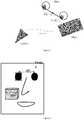
figure 1 : une représentation schématique des paramètres pris en compte dans la mesure,figure 2 : une vue schématique d'une image obtenue par la caméra,figure 3 : un schéma des éléments intervenants dans la prise de mesures.
figure 1 : a schematic representation of the parameters taken into account in the measurement,figure 2 : a schematic view of an image obtained by the camera,figure 3 : a diagram of the elements involved in taking measurements.
Afin d'obtenir la mesure d'une grandeur particulière (PD, monoPD, hauteur) à partir d'une image, nous proposons d'effectuer un report de mesure. En effet, connaissant la taille réelle d'un objet présent dans l'image, il est possible d'obtenir une estimation de la taille réelle de la grandeur souhaitée en comparant leur taille en pixel dans l'image. Contrairement aux systèmes existants n'imposant pas de contraintes sur le regard du sujet et sur la façon de positionner l'objet mire, notre procédé permet d'utiliser le report de mesure de manière optimale en contrôlant ainsi la précision de la mesure.In order to obtain the measurement of a particular quantity (PD, monoPD, height) from an image, we propose to carry out a measurement transfer. Indeed, knowing the real size of an object present in the image, it is possible to obtain an estimate of the real size of the desired quantity by comparing their size in pixels in the image. Unlike existing systems that do not impose constraints on the subject's gaze and on the way to position the target object, our process allows the measurement transfer to be used optimally, thus controlling the measurement accuracy.
En effet, l'ensemble des protocoles proposés sont soumis à des erreurs de parallaxe et de reports induites par la distance entre l'objet de référence et l'objet à mesurer, à savoir les mesures de distance oculaire, ainsi que l'orientation des plans contenants objets de référence et objet de mesure. Bien qu'en théorie il soit possible d'effectuer un report de mesure de deux objets dans une image, la précision nécessaire pour les mesures oculaires n'est jamais garantie lors de la réalisation du protocole, du fait de contraintes théoriques et pratiques non respectées.Indeed, all of the proposed protocols are subject to parallax and transfer errors induced by the distance between the reference object and the object to be measured, namely the ocular distance measurements, as well as the orientation of the plans containing reference objects and measurement object. Although in theory it is possible to carry out a measurement transfer of two objects in an image, the precision necessary for the ocular measurements is never guaranteed during the realization of the protocol, because of theoretical and practical constraints not respected. .
Nous listons ici les cas d'erreur pour une mesure à partir d'une seule image et d'une caméra quelconque. Ces cas d'erreur sont communément commis dans toutes les techniques de reports de mesure existantes à partir d'un objet connu.We list here the error cases for a measurement from a single image and from any camera. These cases of error are commonly committed in all existing measurement transfer techniques from a known object.
Au niveau du protocole de réalisation, nous considérons que l'utilisateur positionne une mire (objet de dimensions connues) planaire en l'appuyant contre son visage, centré au niveau des yeux, c'est-à-dire sur la bouche ou sur le front, afin de former un système rigide visage/mire.In terms of the production protocol, we consider that the user positions a planar target (object of known dimensions) by pressing it against his face, centered at eye level, that is to say on the mouth or on the forehead, to form a rigid face / staff system.
Dans le cas d'une image fixe (issue d'une photographie, vidéo ou flux temps-réel), nous considérons inconnus les paramètres intrinsèques de la caméra. Si nous considérons un modèle en trou d'épingle, le paramètre le plus influent pour les erreurs est la distance focale, et dans une moindre mesure pour les caméras actuelles, la position du centre optique et les distorsions radiales. Lors de la prise de vue, des erreurs de réalisation pratiques, qui influent sur les valeurs et les confiances de ces paramètres, peuvent survenir et se combiner entres elles, mais aussi avec les imprécisions des paramètres de la numérisation de l'image : résolution, qualité et dynamique (compensations, etc.) du capteur, compression de l'image.In the case of a still image (from a photograph, video or real-time stream), we consider the intrinsic parameters of the camera to be unknown. If we consider a pinhole model, the most influential parameter for errors is the focal length, and to a lesser extent for current cameras, the position of the optical center and radial distortions. During the shooting, practical errors of realization, which influence the values and the confidence of these parameters, can occur and combine between them, but also with the inaccuracies of the parameters of the digitization of the image: resolution, sensor quality and dynamics (compensations, etc.), image compression.
Pour les paramètres liés au modèle de caméra et à la scène, et pour un report de mesure 2D dans le plan image, entre la mire de taille connue, et la grandeur à mesurer, la distance entre les centres des pupilles, on note les configurations suivantes :
- Relation du système rigide utilisateur/mire (noté dans la suite UM),par rapport à la caméra (voir
figure 1 )- ∘ Position :
- ▪ Distance : plus le système Utilisateur / Mire (UM) est proche de la caméra, moins les relations de distances entre les points visibles de la mire et du visage sont conservées entre l'image et la scène 3D. Ces relations et points du système utilisateur / mire UM en 3D peuvent même disparaître dans l'image en fonction de la distance à la caméra, comme par exemple les oreilles qui disparaissent du champ de visibilité lorsqu'on s'approche très près. Plus le système utilisateur / mire UM est loin de la caméra, plus l'on se rapproche d'un modèle de projection orthographique, c'est-à-dire que les relations de mesure visibles sur l'image sont conservées par rapport à la réalité. Cela est vrai pour tous les points qui ne sont pas situés sur un plan fronto-parallèle au plan image de la caméra.
- ▪ Position dans l'image : plus le système utilisateur / mire UM est aligné avec l'axe optique, et donc centré dans l'image pour la majorité des caméras, moins il y a d'erreur sur la mesure. Si les plans mire et mesure à effectuer (distance pupillaire) sont confondus, le report de mesure peut comporter un biais si les grandeurs à mesurer ne sont pas centrées. Lorsqu'on effectue un report de mesure pour une grandeur horizontale et que le sujet est bien centré dans l'image, alors l'erreur de report de distances est centrée, et ne dépend plus que de la distance entre les plans de mesure et de référence si ces plans sont fronto-parallèles à la caméra.
Ainsi, pour effectuer un report de mesure, le système utilisateur / mire UM doit se situer loin de la caméra (appelée faible perspective, proche de la vue orthographique) et au centre de l'image. Il doit aussi être symétrique et centré entre les grandeurs à mesurer (distance entre les yeux) et les grandeurs de référence (objet mire) selon les dimensions nécessaires à la mesure.
- ∘ Orientation : dans le cas où le système est orienté par rapport à la caméra (visage tourne vers la droite ou la gauche, ou haut ou bas), il n'est possible d'effectuer un report de mesure qu'on appellera suffisant que dans le cas où grandeur de référence et grandeur à mesurer unidimensionnelle sont sur le même plan, centrées, de taille comparable, et d'orientation faible. Sinon, en théorie (voir par exemple :"Multiple View Geometry") les transformations projectives ne conservant que le birapport, il faut une relation particulière entre 8 points de la scène pour pouvoir effectuer le report de mesure. Cette configuration est possible et amène à une interprétation métrique 3D. Par contre, pour un report de mesure 2D sur l'image, les erreurs vont grandir très vite avec l'orientation, d'autant plus vite que les grandeurs à mesurer sont décentrées.
- ∘ Position :
- Relation Objet mire, caméra
Les conclusions sont ici les mêmes que ci-dessus. - Relation Objet mire, visage
- ∘ Position profondeur : si l'objet mire est dans le même plan que la grandeur à mesurer, alors, un report peut être fait. Si les plans sont décalés en profondeur par rapport à la caméra, l'erreur de report de mesure commise va dépendre de la relation entre la distance caméra et la distance Mire/Utilisateur. Plus le couple utilisateur / mire UM est loin de la caméra, plus l'erreur de report due au décalage de profondeur est petite. Plus le couple utilisateur / mire UM est près, plus l'erreur de mesure est importante au regard de la précision attendue.
- ∘ Position et éloignement : plus l'objet mire est éloigné des yeux, plus l'erreur sur le report est grande. En effet, les erreurs de parallaxe dues à la position dans l'image interviennent dans la mesure elles-mêmes de chaque entité et faussent le rapport entre les objets mire et yeux. Si l'on considère que le visage est situé au centre de l'image le long d'un axe de symétrie vertical passant par le nez, alors on positionnera aussi la mire telle que la mesure soit répartie équitablement de part et d'autre de la projection du centre optique dans l'image, afin de limiter les erreurs de parallaxe intrinsèques à la position de la mire et relativement à la grandeur à mesurer sur le visage.
- ∘ Orientation : l'orientation apporte aussi le problème de parallaxe vu plus haut.
- ∘ Forme de l'objet : l'objet doit être petit (autour d'une dizaine de centimètres) et plan, afin de tenir le stablement possible sur la bouche et le menton, ou sur le front. Des objets mire trop grands, lourds ou épais ne permettent pas une telle stabilité. Un Smartphone qui afficherait une image plane peut être utilisé, mais son poids comparativement à une carte de crédit ou un CD (Compact Disk) est plus important et apporte moins de confort de positionnement.
- ∘ Contact rigide : si l'objet mire n'est pas en contact rigide avec le visage, il n'y a aucune garantie pour le report de mesure. Le protocole pour lequel cet objet est tenu dans un plan de même profondeur que celui des yeux est soumis aux erreurs de parallaxe, et n'offre en pratique aucune garantie que le décalage de profondeur entre les plans est faible. Les utilisateurs commettent en général une erreur non centrée de l'ordre du centimètre, ce qui est trop imprécis pour atteindre la qualité de mesure désirée pour le report. Le contact doit être un contact plan, c'est-à-dire que l'objet mire doit avoir au moins 3 points de contacts non alignés, pour assurer la stabilité du positionnement. La solution qui consiste, dans le cas du protocole précédent, à mettre une carte de crédit en contact sur la tranche au niveau des yeux, va nécessiter la rotation de la tête ainsi que la connaissance du calibrage pour retrouver à partir de plusieurs images la position et l'orientation de l'objet mire.
- Relation of the rigid user / target system (noted in the following UM),compared to the camera (see
figure 1 )- ∘ Position:
- ▪ Distance: the closer the User / Staff (UM) system is to the camera, the less distance relationships between the visible points of the staff and the face are preserved between the image and the 3D scene. These relationships and points of the UM user / target system in 3D can even disappear in the image depending on the distance from the camera, for example the ears which disappear from the field of view when approaching very close. The farther away the user / target UM system is from the camera, the closer we get to an orthographic projection model, i.e. the measurement relationships visible on the image are preserved with respect to the reality. This is true for all the points which are not located on a front-parallel plane to the image plane of the camera.
- ▪ Position in the image: the more the user system / UM target is aligned with the optical axis, and therefore centered in the image for the majority of cameras, the less error there is in the measurement. If the target and measurement planes to be performed (pupillary distance) are the same, the measurement transfer may be biased if the quantities to be measured are not centered. When a measurement transfer is carried out for a horizontal quantity and the subject is well centered in the image, then the distance transfer error is centered, and only depends on the distance between the measurement planes and reference if these planes are fronto-parallel to the camera.
Thus, to carry out a measurement transfer, the user / target UM system must be located far from the camera (called low perspective, close to the orthographic view) and in the center of the image. It must also be symmetrical and centered between the quantities to be measured (distance between the eyes) and the reference quantities (target object) according to the dimensions necessary for the measurement.
- ∘ Orientation: if the system is oriented in relation to the camera (face turns to the right or the left, or up or down), it is only possible to carry out a measurement transfer which will be called sufficient only in the case where the reference quantity and the unidimensional quantity to be measured are on the same plane, centered, of comparable size, and of weak orientation. Otherwise, in theory (see for example:"Multiple View Geometry") the projective transformations keeping only the cross ratio, a special relation between 8 points of the scene is necessary to be able to carry out the measurement transfer. This configuration is possible and leads to a 3D metric interpretation. On the other hand, for a 2D measurement transfer to the image, the errors will grow very quickly with the orientation, all the more quickly as the quantities to be measured are off-center.
- ∘ Position:
- Target object, camera relationship
The conclusions here are the same as above. - Target object relation, face
- ∘ Depth position: if the target object is in the same plane as the quantity to be measured, then a report can be made. If the plans are shifted in depth in relation to the camera, the measurement transfer error made will depend on the relationship between the camera distance and the Target / User distance. The farther away the user / staff pair UM is from the camera, the smaller the carryover error due to the depth offset. The closer the user / target UM pair, the greater the measurement error with regard to the expected accuracy.
- ∘ Position and distance: the further the target object is from the eyes, the greater the error on the transfer. In fact, the parallax errors due to the position in the image intervene in the measurement themselves of each entity and distort the relationship between the target and eye objects. If we consider that the face is located in the center of the image along a vertical axis of symmetry passing through the nose, then we will also position the test chart such that the measurement is distributed equally on either side of the the projection of the optical center in the image, in order to limit the parallax errors intrinsic to the position of the staff and relative to the size to be measured on the face.
- ∘ Orientation: orientation also brings the parallax problem seen above.
- ∘ Shape of the object: the object must be small (around ten centimeters) and flat, in order to hold as stably as possible on the mouth and chin, or on the forehead. Target objects that are too large, heavy or thick do not allow such stability. A Smartphone that would display a flat image can be used, but its weight compared to a credit card or CD (Compact Disk) is more important and brings less comfort of positioning.
- ∘ Rigid contact: if the target object is not in rigid contact with the face, there is no guarantee for the measurement deferral. The protocol for which this object is held in a plane of the same depth as that of the eyes is subject to parallax errors, and in practice offers no guarantee that the depth shift between the planes is small. Users generally commit an off-center error of the order of a centimeter, which is too imprecise to achieve the desired measurement quality for the transfer. The contact must be a plane contact, i.e. the target object must have at least 3 non-aligned contact points, to ensure positioning stability. The solution which consists, in the case of the previous protocol, in putting a credit card in contact on the slice at eye level, will require the rotation of the head as well as knowledge of calibration to find from several images the position and orientation of the target object.
L'ensemble de ces contraintes favorise une mire de taille limitée, positionnée autour de la grandeur à mesurer. La mire idéale est une paire de lunettes de taille connue sur la face, et de distance face-œil connue. Cette mire permet un placement idéal en position, et aide à une orientation de face par projection symétrique de la surface visible des branches dans l'image. Un autre type de mire qui correspond est une carte de crédit ou un CD, que l'on situe préférentiellement sur la zone bouche-menton ou sur le front.All of these constraints favor a test pattern of limited size, positioned around the quantity to be measured. The ideal target is a pair of glasses of known size on the face, and of known face-to-eye distance. This test pattern allows an ideal placement in position, and helps a face orientation by symmetrical projection of the visible surface of the branches in the image. Another type of target that corresponds is a credit card or a CD, which is preferably placed on the mouth-chin area or on the forehead.
Le système des iris est non rigide. On considère les centres des globes oculaires comme centres de rotation de l'œil. Sont visibles depuis la camera l'iris et la pupille.
- ∘ Visée : lors des protocoles habituels de mesure réalisés dans les magasins d'optique, l'utilisateur regarde à l'infini afin de mesurer la mesure distance pupillaire à l'infini. On considère que la mesure du regard à l'infini peut être faite quand le sujet regarde à un point situé à plus d'une distance seuil'ds' (généralement un mètre, mais on peut descendre à 70cm et augmenter à l'infini), dans le cadre d'un report de mesure sur une image.
Les deux protocoles possibles dans le cadre de notre système sont les suivants :- 1. L'utilisateur doit viser un point situé derrière la caméra à plus de la distance seuil ds.
- 2. L'utilisateur doit se situer à plus de la distance seuil ds et regarder la caméra ou un point proche.
- ∘ Convergence : la vision de l'utilisateur est plus ou moins précise, et sa capacité de convergence sur le point à viser peut varier. Dans le cas général, l'utilisateur ayant un problème de vue, sa capacité à viser correctement est limitée. Le fait qu'il soit à un peu moins d'un mètre du point de visée ne perturbe pas précision de la mesure. Pour un utilisateur qui voit bien, sa capacité à bien converger va imposer de se tenir loin pour respecter les conditions de visée à l'infini, qui permettent la mesure 2D.
- ∘ Aiming: during the usual measurement protocols carried out in optical stores, the user looks at infinity in order to measure the pupillary distance measurement at infinity. It is considered that the measurement of gaze at infinity can be made when the subject is looking at a point located more than a threshold distance'ds' (generally one meter, but one can descend to 70cm and increase to infinity) , as part of a measurement transfer to an image.
The two possible protocols within the framework of our system are as follows:- 1. The user must aim at a point behind the camera more than the threshold distance ds.
- 2. The user must be more than the threshold distance ds and look at the camera or a nearby point.
- ∘ Convergence: the user's vision is more or less precise, and his ability to converge on the point to be aimed can vary. In the general case, the user having a sight problem, his ability to aim correctly is limited. The fact that it is a little less than a meter from the aiming point does not interfere with the accuracy of the measurement. For a user who sees well, his ability to converge well will require standing far to respect the infinity aiming conditions, which allow 2D measurement.
Plus l'utilisateur est loin de la caméra, moins l'erreur de convergence ou visée sera importante.The further the user is from the camera, the less the convergence or aim error will be.
Une autre source d'erreur est la précision de l'image. Afin de pouvoir effectuer un report de mesure, il faut repérer sur l'image obtenue des amers, qui permettent d'effectuer le report. En général, les systèmes proposés demandent de spécifier une longueur connue sur l'objet mire et le centre des pupilles sur les yeux. Le problème alors rencontré et non traité par les systèmes existants et l'erreur de pointage et de repérage de ces amers, qui est faite par un humain le plus souvent, ou un algorithme de reconnaissance, mais dont l'imprécision est telle que c'est une source d'erreur plus importante que l'erreur de parallaxe décrite plus haut pour des capteurs classiques.Another source of error is the accuracy of the image. In order to be able to carry out a measurement transfer, it is necessary to locate on the image obtained landmarks, which allow the transfer to be carried out. In general, the proposed systems require specifying a known length on the target object and the center of the pupils on the eyes. The problem then encountered and not dealt with by the existing systems and the error of pointing and locating these landmarks, which is made by a human most often, or a recognition algorithm, but whose imprecision is such that it is is a greater source of error than the parallax error described above for conventional sensors.
D'une part, le système de numérisation de la scène réelle à l'image numérique finale additionne un nombre de traitements classiques inhérents aux capteurs numériques grand public : quantification, compression [autres]. La qualité des capteurs augmente avec le temps, mais la qualité de l'image n'est pas toujours bonne à cause de la combinaison de plusieurs facteurs connus comme la sensibilité du capteur, les conditions lumineuses, le temps de transfert matériel de la donnée numérique qui impose des contraintes de taille et de compression. L'image finale est souvent bruitée, saturée ou manque de dynamique, ce qui a pour effet de limiter la précision de la localisation des amers. Les capteurs peuvent avoir des résolutions élevées, les algorithmes de compression apportent beaucoup d'imprécision sur les contours ou en hallucinent de nouveaux. Sur un capteur HD webcam le contour d'un objet plan peut faire plusieurs pixels de large.On the one hand, the system for digitizing the real scene to the final digital image adds a number of conventional treatments inherent in digital sensors for the general public: quantization, compression [others]. The quality of the sensors increases over time, but the quality of the image is not always good due to the combination of several known factors such as the sensitivity of the sensor, the light conditions, the material transfer time of the digital data which imposes size and compression constraints. The final image is often noisy, saturated or lacking in dynamics, which has the effect of limiting the accuracy of the location of landmarks. The sensors can have high resolutions, the compression algorithms bring a lot of imprecision on the contours or hallucinate new ones. On an HD webcam sensor, the outline of a flat object can be several pixels wide.
D'autre part, le repérage d'amers stables entre les images est difficile à cause de l'imprécision de l'image. Les systèmes actuels laissent l'utilisateur référencer ces amers, qui ne sont pas des opérateurs experts. L'erreur commise sur le pointage de l'amer désiré est très grande. Les algorithmes de détection n'étant jamais fiables à 100%, particulièrement pour des données très bruitées, les systèmes automatiques peuvent obtenir des erreurs aussi grossières qu'un humain inexpérimenté. La précision de pointage de l'amer étant perturbée par la visibilité et le pointage lui-même, les erreurs s'additionnent et on peut atteindre des erreurs de plusieurs pixels.On the other hand, locating stable landmarks between images is difficult due to the imprecision of the image. Current systems let the user reference these landmarks, which are not expert operators. The error made in pointing to the desired bitterness is very great. Since detection algorithms are never 100% reliable, especially for very noisy data, automatic systems can get errors as gross as an inexperienced human. Since the pointing accuracy of the lander is disturbed by the visibility and the pointing itself, the errors add up and one can reach errors of several pixels.
Sur les images de capteurs grand public, et avec les contraintes de placement de l'utilisateur, ces pixels d'erreur représentent plusieurs millimètres, ce qui rend la précision de la mesure de la distance pupillaire insuffisante.On the images of general public sensors, and with the positioning constraints of the user, these error pixels represent several millimeters, which makes the precision of the measurement of the pupillary distance insufficient.
Nous déduisons de l'analyse précédente les protocoles optimaux en fonction des types de capteur grand public:
- Avec une seule image :
- Appareil photo: Avec des bons capteurs, comme des appareils photos, le protocole idéal est de se positionner de face et à plus de deux mètres. Il faut alors deux personnes (une pour prendre la photo), ou disposer d'un déclencheur automatique. En pratique, la position et l'orientation du système UM ne sont pas garantis : il faut que les deux personnes aient la même taille pour éviter les erreurs de parallaxe dus à la position, et obtenir une image pour laquelle l'orientation du visage est faible. Il faut donc réaliser un alignement des positions et orientations respectives des systèmes UM et caméra. Un protocole possible est que les deux personnes soient assises sur des chaises, afin de limiter leur différence de taille, à une distance la plus éloignée telle que l'utilisateur peut encore regarder l'objectif. Deux mètres sont suffisants en pratique. L'alignement des orientations entre les systèmes UM et caméra peut être faite avec les recommandations de positionnement de l'utilisateur proposées dans ce brevet. Comme le système de prise de vue n'a pas d'écran, les indications de positionnement ne sont pas effectuées par le logiciel mais par la personne qui prend la photo.
- Webcam : la webcam, intégrée ou non, est positionnée en général au-dessus de l'écran. Mêmes pour les capteurs de qualité, la compression de l'image est souvent forte, ainsi que la présence de traitements de l'image qui modifient les contours, et le réglage des paramètres de luminosité, balances des blancs et autres paramètres souvent adaptés de manière automatique très influents. Ces effets perturbent la position perçue des amers. La webcam se règle pour une lumière neutre. L'utilisateur se place assis face à la caméra. Le programme qui contrôle la caméra prend la photo automatiquement. L'utilisateur devant être le plus loin possible, il faut trouver le meilleur compromis entre taille dans l'image qui doit être maximale et distance à la caméra. L'utilisateur doit se placer environ à une distance d'un bras, entre 70cm et 1m. Le programme lui retourne en temps réel l'image du flux acquis sur l'écran, et l'image est zoomée et contient un guide ovale en son centre tel que l'utilisateur se place dedans. Ainsi, les contraintes de centrage et position sont respectées.
Un guide sur la visibilité des deux oreilles pour l'angle d'orientation gauche-droite, ainsi qu'un guide d'alignement des yeux horizontal avec l'axe du dessus des oreilles (endroit où les branches sont posées) pour l'orientation haut-bas sont affichés.
Une variante à l'affichage d'un guide est de mettre en place un système de suivi de visage en 3D qui permet de prendre la photo optimale (meilleure pose 3D du visage) en faisant des retours temps réel sur l'orientation du visage de l'utilisateur. - • Capteur mobile (smartphone tablette) : les mêmes guides sont affichés grâce à un programme web ou une application. L'utilisateur peut se prendre seul avec la camera frontale qui lui renvoie son image, comme dans le cas de la webcam, ou peut être assistée d'une personne qui suit les guides pour permettre un bonne visée et réalisation du protocole, comme dans le cas ce l'appareil photo. Le cas où l'utilisateur se prend seul est propice aux erreurs de réalisation du protocole, car toutes les contraintes que nous mettons à jour n'ont pas la garantie d'être respectées.
La variante décrite précédemment s'applique aussi dans ce cas.
Dans ces 3 cas décrits, une variante à l'utilisation d'une mire plane est possible en utilisant le modèle 3D métrique du visage (ou d'une partie du visage) de l'utilisateur (possibilité de scanner son visage au préalable, possibilité d'uploader son modèle 3D dans l'application). Après un recalage entre des points 2D du visage issus de l'image et de leurs correspondants sur le modèle 3D métrique, la mire sera alors constituée d'au moins 2 points 3D particuliers du modèle 3D de visage. Selon la densité du maillage 3D de visage de l'utilisateur, celui pourra alors aussi servir au suivi de visage proposé dans la variante précédente. En résumé, la connaissance du visage 3D métrique de l'utilisateur permet de faire un suivi de visage et le report de mesure sur des amers du visage 3D. - • Position et orientation du système UM
A partir de quelques images en nombre faible (inférieur à cinq), on considère que les yeux regardent un point à l'infini et que la direction du regard est alignée avec celle du système UM, c'est-à-dire dans une direction quasi perpendiculaire au plan de la mire plane. Si on considère que les yeux bougent et suivent un point indépendamment de l'orientation du visage, alors on revient dans le cas du brevet précédentFR 10 52001 - ∘ CAS 1 : système des yeux dans le même plan que le plan mire, un point de vue.
Si on considère le système des yeux dans un même plan ou un plan proche que celui de la mire, alors, pour une mire plane, on peut définir une relation homographique entre un espace de référence métrique et l'image. Cette relation peut s'écrire :
xref_i=H* x_i, avecx_i des points homogènes dansP3, espace projectif de dimension 3.
Il est alors possible d'effectuer un report de mesure non plus directement sur l'image entre les pointsx_i, mais dans un espace de l'image normalisée qui garantit la conservation des distances, entre les pointsxref_i, définis comme les images desx_i par une homographieH. La mise en oeuvre de cette mesure corrigée peut s'effectuer à partir d'une seule vue ou de plusieurs images, à des position et orientation de UM différentes.
Cette approche permet de minimiser les erreurs de précision du référencement des points d'intérêt dans les images. - CAS 2 : système des yeux dans des plans différents que celui de la mire, un point de vue
On ne peut pas effectuer de rapport de mesure fiable dans ce cas général à partir d'une seule image, à part dans le cas ou l'orientation est faible et la distance UM à la caméra est grande, ou les erreurs sont négligeables devant l'échelle de la mesure.
- ∘ CAS 1 : système des yeux dans le même plan que le plan mire, un point de vue.
- Avec plusieurs images :
- 1/ Si la caméra n'est pas calibrée, les scénarios décrits précédemment peuvent être utilisés sur plusieurs images ce qui permet de rendre la mesure robuste en s'intéressant à la statistique des mesures (comme par exemple la moyenne ou l'écart type).
- 2/ caméra en mouvement et utilisateur qui regarde un point à l'infini sans bouger. L'utilisateur qui réalise la prise de vue n'a besoin d'effectuer qu'un petit déplacement. La mire doit être visible dans le mouvement et positionnée de manière rigide par rapport au visage. A partir d'un nombre grand d'images acquises (deux en théorie), ou d'une vidéo, on peut reconstruire en 3D par des techniques classiques le système rigide UM de façon métrique dans le cas où la caméra est calibrée.
Une variante est de remplacer la mire plane par l'utilisation d'un modèle 3D métrique du visage (ou d'une partie du visage) de l'utilisateur (possibilité de scanner son visage au préalable, possibilité d'uploader son modèle 3D dans l'application).
Si la caméra n'est pas calibrée, il n'est pas possible d'estimer la relation métrique entre la mire et les yeux, et on se ramène au cas où il faut la définir (même plan ou non, relation rigide 3D, etc.). Le problème pratique qui se pose est alors celui de la précision numérique de cette relation, qui dépend de la résolution d'image, de la distance et de la taille de l'objet mire par rapport à la précision requise sur la mesure à effectuer. En général, pour une précision de l'ordre de 0.5 millimètres sur la distance pupillaire, la précision requise de la relation à définir entre caméra et yeuxCY est du même ordre, ce qui est impossible à obtenir dans la réalité.
Prenons l'exemple que l'on connaît la taille et la morphologie 3D du visage de l'utilisateur, le visage constitue pour les yeux la meilleure mire que l'on peut obtenir. Si l'on veut mesurer la distance entre les centres des pupilles, alors il faut déterminer la relation de la profondeur du plan des pupilles par rapport à ce visage, et une erreur de l'ordre de demi-millimètre apporte une imprécision du même ordre.
Enfin, étant dans un contexte non calibré, la résolution avec relation homographique et une seule image est suffisante, puisqu'elle permet le report de mesure dans un espace normalisé. L'approche 3D ici décrite amène cependant une stabilité sur la mesure, puisque le nombre d'images et l'orientation de l'utilisateur qui réalise la prise de vue avec la caméra permettent d'obtenir une statistique de la mesure, et de caractériser ainsi la loi de l'erreur commise. Une manière de procéder est de reconstruire le système Yeux/Mire de la manière suivante (voirfigure 1 ):- A / Trouver tout d'abord la transformation (Translation, Rotation) subit par l'ensemble des points de la mire dans chaque image acquise.
Pour chaque image, une minimisation par différence de points est réalisée (minimisation classiquement résolue par des algorithmes de type Gauss-Newton). Nous cherchons à minimiser l'expression suivante :
- Rm, matrice de rotation 3D entre caméra et mire,
- Tm, vecteur translation 3D entre caméra et mire,,
- nPts, nombre de points projetés,
- P3D, coordonnées 3D de la mire,
- P2D, coordonnées 2D de la mire dans l'image (coins, points contours, points caractéristiques),
- Proj, fonction projetant un point 3D dans l'image (modèle sténopé par exemple),


- etKM, matrice de calibrage de la caméra (précisions dans la partie calibrage)

- Dp, étant la fonction appliquant la matrice de rotation R et le vecteur de translationT à un point 3D pour un déplacement en 3D

- B/ Trouver ensuite la valeur de chaque variableTSM, RSM ethpd communes à l'ensemble des images acquises.
Avec :- hpd, distance entre le centre du système des yeux et le centre de chaque pupille,
- Rsm, matrice de rotation 3D rigide entre la mire et le système des yeux,
- Tsm, vecteur translation 3D rigide entre la mire et le système des yeux,
- A / Trouver tout d'abord la transformation (Translation, Rotation) subit par l'ensemble des points de la mire dans chaque image acquise.


- With a single image:
- Camera: With good sensors, such as cameras, the ideal protocol is to position yourself face-to-face and more than two meters away. You then need two people (one to take the picture), or have an automatic shutter release button. In practice, the position and orientation of the UM system are not guaranteed: both people must have the same height to avoid parallax errors due to the position, and to obtain an image for which the orientation of the face is weak. It is therefore necessary to carry out an alignment of the respective positions and orientations of the UM and camera systems. One possible protocol is for the two people to be seated on chairs, in order to limit their height difference, at the farthest distance such that the user can still look at the lens. Two meters are sufficient in practice. The alignment of the orientations between the UM and camera systems can be made with the user positioning recommendations proposed in this patent. As the shooting system does not have a screen, the positioning indications are not made by the software but by the person taking the photo.
- Webcam: the webcam, integrated or not, is generally positioned above the screen. Even for quality sensors, the compression of the image is often strong, as well as the presence of image processing which modifies the contours, and the adjustment of the parameters of brightness, white balances and other parameters often adapted in a way. very influential automatic. These effects disrupt the perceived position of landmarks. The webcam adjusts for neutral light. The user sits in front of the camera. The program that controls the camera takes the photo automatically. Since the user must be as far away as possible, the best compromise must be found between size in the image, which must be maximum, and distance from the camera. The user should stand approximately an arm's length away, between 70cm and 1m. The program returns the image of the stream acquired on the screen in real time, and the image is zoomed in and contains an oval guide in its center as the user places himself in it. Thus, the constraints of centering and position are respected.
A guide to the visibility of both ears for the left-right orientation angle, as well as a horizontal eye alignment guide with the axis of the top of the ears (where the branches are laid) for orientation up-down are displayed.
A variant of the display of a guide is to set up a 3D face tracking system which makes it possible to take the optimal photo (best 3D pose of the face) by providing real-time feedback on the orientation of the face of the user. - • Mobile sensor (smartphone tablet): the same guides are displayed using a web program or an application. The user can take himself alone with the front camera which sends back his image, as in the case of the webcam, or can be assisted by a person who follows the guides to allow a good aiming and realization of the protocol, as in the case this the camera. The case where the user takes himself alone is conducive to errors in the implementation of the protocol, because all the constraints that we update are not guaranteed to be respected.
The variant described above also applies in this case.
In these 3 cases described, a variant to the use of a flat pattern is possible by using the metric 3D model of the face (or of a part of the face) of the user (possibility of scanning his face beforehand, possibility to upload its 3D model in the application). After a registration between the 2D points of the face coming from the image and their correspondents on the metric 3D model, the test pattern will then consist of at least 2 particular 3D points of the 3D model of the face. Depending on the density of the 3D mesh of the user's face, it can then also be used for the face tracking proposed in the previous variant. In summary, knowledge of the user's metric 3D face allows face tracking and measurement transfer to 3D face landmarks. - • Position and orientation of the UM system
From a few images in low number (less than five), it is considered that the eyes are looking at a point at infinity and that the direction of the gaze is aligned with that of the UM system, that is to say in a direction almost perpendicular to the plane of the flat staff. If we consider that the eyes move and follow a point independently of the orientation of the face, then we come back to the case of the previous patent.FR 10 52001 - ∘ CASE 1: eye system in the same plane as the target plane, a point of view.
If we consider the eye system in the same plane or a plane close to that of the test pattern, then, for a plane test pattern, we can define a homographic relation between a metric reference space and the image. This relation can be written:
xref_i =H * x_i, withx_i homogeneous points inP3, projective space of dimension 3.
It is then possible to carry out a measurement transfer no longer directly on the image between the pointsx_i, but in a space of the normalized image which guarantees the conservation of the distances, between the pointsxref_i, defined as the images of thex_i by anH homography. The implementation of this corrected measurement can be carried out from a single view or from several images, at different UM position and orientation.
This approach makes it possible to minimize errors in the precision of referencing points of interest in the images. - CASE 2: eye system in different planes than that of the staff, a point of view
In this general case, a reliable measurement report cannot be made from a single image, except in the case where the orientation is small and the distance UM to the camera is large, or the errors are negligible compared to the 'measurement scale.
- ∘ CASE 1: eye system in the same plane as the target plane, a point of view.
- With several images:
- 1 / If the camera is not calibrated, the scenarios described above can be used on several images which makes it possible to make the measurement robust by focusing on the statistics of the measurements (such as for example the mean or the standard deviation) .
- 2 / moving camera and user looking at an infinite point without moving. The user who takes the picture only needs to make a small movement. The staff must be visible in the movement and positioned rigidly in relation to the face. From a large number of acquired images (two in theory), or from a video, the rigid UM system can be reconstructed in 3D by conventional techniques in a metric manner if the camera is calibrated.
A variant is to replace the flat pattern by using a metric 3D model of the user's face (or part of the face) (possibility of scanning his face beforehand, possibility of uploading his 3D model in application).
If the camera is not calibrated, it is not possible to estimate the metric relation between the sight and the eyes, and we come back to the case where it must be defined (same plane or not, rigid 3D relation, etc. .). The practical problem which arises is then that of the numerical precision of this relation, which depends on the image resolution, on the distance and on the size of the target object compared to the precision required on the measurement to be carried out. In general, for a precision of the order of 0.5 millimeters on the pupillary distance, the required precision of the relationship to be defined between camera and eyesCY is of the same order, which is impossible to obtain in reality.
Let us take the example that we know the size and the 3D morphology of the user's face, the face constitutes for the eyes the best test pattern that can be obtained. If we want to measure the distance between the centers of the pupils, then we must determine the relation of the depth of the plane of the pupils with respect to this face, and an error of the order of half a millimeter brings an imprecision of the same order .
Finally, being in an uncalibrated context, the resolution with homographic relation and a single image is sufficient, since it allows the measurement to be transferred in a standardized space. The 3D approach described here, however, brings stability to the measurement, since the number of images and the orientation of the user who takes the picture with the camera make it possible to obtain a statistic of the measurement, and to characterize thus the law of the error committed. One way to do this is to rebuild the Eye / Target System as follows (seefigure 1 ):- A / First of all, find the transformation (Translation, Rotation) undergone by all the test points in each acquired image.
For each image, a minimization by difference of points is carried out (minimization conventionally solved by Gauss-Newton type algorithms). We try to minimize the following expression:- Rm, 3D rotation matrix between camera and staff,
- Tm, 3D translation vector between camera and staff,
- nPts, number of projected points,
- P3D , 3D coordinates of the staff,
- P2D , 2D coordinates of the test pattern in the image (corners, contour points, characteristic points),
- Proj, function projecting a 3D point in the image (pinhole model for example),
- andKM, camera calibration matrix (details in the calibration section)
- Dp , being the function applying the rotation matrix R and the translation vectorT to a point 3D for a displacement in 3D
- B / Then find the value of each variableTSM , RSM andhpd common to all the images acquired.
With :- hpd, distance between the center of the eye system and the center of each pupil,
- Rsm, rigid 3D rotation matrix between the staff and the eye system,
- Tsm, rigid 3D translation vector between the staff and the eye system,
- A / First of all, find the transformation (Translation, Rotation) undergone by all the test points in each acquired image.
Sur l'ensemble des images, minimisation par différence de points
- Rm, matrice de rotation 3D de la mire (par image),
- Tm, vecteur translation 3D de la mire (par image),
- nPts, nombre de points projetés,
- nlm, nombre d'images acquises,
- P'3D, coordonnées 3D des pupilles,
- P'2D, coordonnées 2D des pupilles dans l'image,
- Proj, fonction projetant un point 3D dans l'image (par exemple par modèle sténopé),
- Dp, fonction appliquant une matrice de rotation R et un vecteur de translationT à un point 3D pour un déplacement en 3D.
- 3/ Caméra fixe et utilisateur en mouvement qui regarde un point à l'infini. La mire doit être visible dans le mouvement et positionnée de manière rigide par rapport au visage. A partir d'un nombre grand d'images acquises, deux en théorie), ou d'une vidéo, on peut reconstruire en 3D par des techniques classiques le système rigide UM de façon métrique dans le cas où la caméra est calibrée.
Une variante est de remplacer la mire plane par l'utilisation d'un modèle 3D métrique du visage. - 4/ Caméra calibrée fixe et utilisateur en mouvement qui regarde plusieurs points sur un écran/plan.
Une variante est de remplacer la mire plane par l'utilisation d'un modèle 3D métrique du visage. - 5/ Caméra calibrée en mouvement et utilisateur fixe qui regarde plusieurs points sur un écran/plan.
Une variante est de remplacer la mire plane par l'utilisation d'un modèle 3D métrique du visage - 6/ Caméra non calibrée fournissant une carte de profondeur (de type Kinect -marque déposée-). Un report de mesure peut être réalisé de manière plus précise puisque dans ce cas, la distance utilisateur caméra et caméra-mire sont connues. Elles ne sont plus simplement estimées comme dans les protocoles avec une seule image.
- 7/ Caméra calibrée fournissant une carte de profondeur (de type Kinect -marque déposée-). Dans ce cas aucune mire n'est nécessaire. Connaissant le calibrage de la caméra ainsi que la profondeur du visage dans la scène, on en déduit directement la distance entre les pupilles.
- 3/ Caméra fixe et utilisateur en mouvement qui regarde un point à l'infini. La mire doit être visible dans le mouvement et positionnée de manière rigide par rapport au visage. A partir d'un nombre grand d'images acquises, deux en théorie), ou d'une vidéo, on peut reconstruire en 3D par des techniques classiques le système rigide UM de façon métrique dans le cas où la caméra est calibrée.
- Rm, 3D rotation matrix of the staff (per image),
- Tm, 3D translation vector of the test pattern (per image),
- nPts, number of projected points,
- nlm, number of images acquired,
- P '3D , 3D coordinates of the pupils,
- P '2D , 2D coordinates of the pupils in the image,
- Proj, function projecting a 3D point in the image (for example by pinhole model),
- Dp , function applying a rotation matrix R and a translation vectorT to a point 3D for a displacement in 3D.
- 3 / Fixed camera and moving user looking at an infinite point. The staff should be visible during movement and positioned rigidly in relation to the face. From a large number of acquired images (two in theory), or from a video, the rigid UM system can be reconstructed in 3D by conventional techniques in a metric manner if the camera is calibrated.
One variation is to replace the flat pattern by using a metric 3D model of the face. - 4 / Fixed calibrated camera and moving user looking at several points on a screen / plane.
One variation is to replace the flat pattern by using a metric 3D model of the face. - 5 / Camera calibrated in motion and fixed user looking at several points on a screen / plane.
A variation is to replace the flat pattern with the use of a metric 3D model of the face. - 6 / Uncalibrated camera providing a depth map (Kinect type - registered trademark -). A measurement transfer can be carried out in a more precise manner since in this case, the distance between the user and the camera-target are known. They are no longer simply estimated as in protocols with a single image.
- 7 / Calibrated camera providing a depth map (Kinect type - registered trademark -). In this case no target is necessary. Knowing the calibration of the camera as well as the depth of the face in the scene, we directly deduce the distance between the pupils.
- 3 / Fixed camera and moving user looking at an infinite point. The staff should be visible during movement and positioned rigidly in relation to the face. From a large number of acquired images (two in theory), or from a video, the rigid UM system can be reconstructed in 3D by conventional techniques in a metric manner if the camera is calibrated.
- Une caméra : webcam, appareil photo, tablette, caméra carte de profondeur,A camera: webcam, camera, tablet, depth map camera,
- Un calculateur, un écran,A calculator, a screen,
- Un protocole précis de positionnement Utilisateur, Mire, Caméra U, M, C,A precise positioning protocol User, Target, Camera U, M, C,
- Un ensemble de consignes interactives qui permet de respecter ce positionnement sans erreur,A set of interactive instructions that allow this positioning to be respected without error,
- Un outil de référencement avec consignes des amers,A referencing tool with instructions for landmarks,
- Un calcul de report de mesure corrigé.A corrected measurement carryover calculation.
Des mires aux propriétés suivantes :
- Surface de contact suffisante pour assurer une stabilité sur le visage
- Autour des yeux, ou le plus proche possible : centré et près des éléments dont on veut effectuer les mesures.
- Des objets qui contiennent une certaine symétrie pour un positionnement aisé.
- Exemples de mire :
- ∘ des lunettes de dimensions et distance face-œil connue (en général 15mm).
- ∘ Une carte de crédit
- ∘ Un CD
- ∘ Un visage de dimensions connues, ou d'éléments constitutifs mesurés (comme les coins des yeux)
- Sufficient contact surface to ensure stability on the face
- Around the eyes, or as close as possible: centered and close to the elements you want to measure.
- Objects that contain a certain symmetry for easy positioning.
- Examples of target:
- ∘ glasses of known dimensions and face-to-eye distance (generally 15mm).
- ∘ A credit card
- ∘ A CD
- ∘ A face of known dimensions, or measured components (such as the corners of the eyes)
Le sujet doit se placer à une distance connue (ou estimable) du dispositif d'acquisition d'image et regarder devant lui (un point particulier ou le dispositif d'acquisition par exemple) en plaçant un objet rigide de taille connue (mire) à une distance connue (ou estimable) du plan contenant les pupilles. Il est rappelé que dans le cas où le visage 3D métrique de l'utilisateur est connu, la mire plane n'est pas nécessaire.The subject must stand at a known (or estimable) distance from the image acquisition device and look in front of him (a particular point or the acquisition device for example) by placing a rigid object of known size (target) at a known (or estimable) distance from the plane containing the pupils. It is recalled that in in the case where the metric 3D face of the user is known, the planar target is not necessary.
Une acquisition d'image du sujet est alors réalisée lorsque sa tête est bien droite face à la caméra (oreilles et yeux quasiment alignés). Idéalement, les 2 oreilles du sujet doivent être visibles de manière équivalente. Un flux vidéo peut être enregistré pendant que l'utilisateur effectue un mouvement particulier de la tête permettant de choisir l'image la plus appropriée. L'image peut aussi être automatiquement choisie grâce à un suivi de visage 3D.An image acquisition of the subject is then carried out when his head is straight in front of the camera (ears and eyes almost aligned). Ideally, the subject's 2 ears should be equally visible. A video stream can be recorded while the user performs a particular head movement to choose the most appropriate image. The image can also be automatically chosen using 3D face tracking.
Le placement idéal de l'objet rigide se situe à une distance fixe ou estimable (statistiquement) du plan contenant les pupilles, une face de l'objet mire devant se trouver le plus parallèle possible à ce plan contenant les pupilles. Par exemple, l'objet rigide peut se trouver sur le front, sur une joue ou sur la bouche.The ideal placement of the rigid object is located at a fixed or estimable distance (statistically) from the plane containing the pupils, one face of the target object having to be as parallel as possible to this plane containing the pupils. For example, the rigid object may be on the forehead, on a cheek or on the mouth.
Les indications pratiques sont les suivantes dans le cas où la mire est une carte de crédit:
- 1. L'utilisateur se positionne assis devant son écran, à une distance d'un bras tendu de la caméra, supposée située en haut de l'écran et centrée. Il doit voir son visage centré dans l'écran.
- 2. S'il est porteur de lunettes, il les retire. Pour la majorité des corrections, notre protocole permet de garantir la qualité de la mesure sans avoir besoin de retirer les lunettes.
- 3. Il positionne la carte sur sa bouche, en veillant à exercer une pression suffisante avec son index pour que la carte soit fixée et respecte la condition de stabilité plane.
- 4. L'utilisateur règle ensuite l'orientation de sa tête en veillant à ce que
- a. En hauteur : la ligne horizontale passant par ses pupilles, ou les coins de ses yeux, soit de même hauteur dans l'image que les points de début d'oreilles au niveau des temps, soit les points sur lesquels reposeraient des branches de lunettes.
- b. En largeur : garantir que l'utilisateur voit les parties gauche et droite de son visage de manière symétrique, grâce à des indices. En positionnement, cela a été traité au point 1. En orientation, cette garantie s'effectue en donnant à l'utilisateur des repères sur l'image qui garantissent une orientation de face sans avoir tourné la tête trop à gauche ou à droite. Par exemple, les deux oreilles doivent être visibles. Les oreilles étant dans un plan éloigné d'au moins 10cm derrière les yeux, tout angle même faible de la tête entraîne un déplacement conséquent de ces objets dans l'image, et une invisibilité due à l'occultation provoquée par la tête depuis le point de vue de la caméra. Les oreilles disparaissent très vite si la tête n'est pas alignée en direction avec la visée de la caméra.
- 5. L'utilisateur regarde la camera
- 6. Le logiciel prend la photo
- 1. The user is positioned seated in front of his screen, at a distance of an outstretched arm from the camera, supposedly located at the top of the screen and centered. He should see his face centered in the screen.
- 2. If he is wearing glasses, he takes them off. For the majority of corrections, our protocol guarantees the quality of the measurement without having to remove the glasses.
- 3. He positions the card on his mouth, making sure to exert sufficient pressure with his index finger so that the card is fixed and respects the condition of flat stability.
- 4. The user then adjusts the orientation of their head making sure that
- To. In height: the horizontal line passing through its pupils, or the corners of its eyes, either of the same height in the image as the starting points of the ears at the level of the times, or the points on which the branches of glasses would rest.
- b. In width: ensure that the user sees the left and right parts of their face symmetrically, thanks to clues. In positioning, this was dealt with in point 1. In orientation, this guarantee is effected by giving the user marks on the image which guarantee a face orientation without having turned the head too much to the left or to the right. For example, both ears should be visible. As the ears are in a plane at least 10cm behind the eyes, any angle, even small of the head, will cause displacement consequence of these objects in the image, and an invisibility due to the obscuration caused by the head from the point of view of the camera. Ears disappear very quickly if the head is not aligned in direction with the aim of the camera.
- 5. The user looks at the camera
- 6. The software takes the picture
Une variante :
- 1. L'utilisateur se positionne assis devant son écran, à une distance d'un bras tendu de la caméra, supposée située en haut de l'écran et centrée. Il doit voir son visage centré dans l'écran.
- 2. S'il est porteur de lunettes, il les retire. L'utilisateur tient la carte à sa disposition.
- 3. Détection et suivi de visage 3D.
- 4. Le suivi de visage aide l'utilisateur à bien positionner son visage.
- 5. L'utilisateur porte la carte sur sa bouche et regarde la caméra.
- 6. Le logiciel prend la photo.
- 1. The user is positioned seated in front of his screen, at a distance of an outstretched arm from the camera, supposedly located at the top of the screen and centered. He should see his face centered in the screen.
- 2. If he is wearing glasses, he takes them off. The user holds the card at his disposal.
- 3. 3D face detection and tracking.
- 4. Face tracking helps the user to position their face correctly.
- 5. The user puts the card over their mouth and looks at the camera.
- 6. The software takes the photo.
Une autre variante (dans le cas où le visage métrique est connu):
- 1. L'utilisateur se positionne assis devant son écran, à une distance d'un bras tendu de la caméra, supposée située en haut de l'écran et centrée. Il doit voir son visage centré dans l'écran.
- 2. S'il est porteur de lunettes, il les retire.
- 3. Détection et suivi de visage 3D métrique.
- 4. Le suivi de visage aide l'utilisateur à bien positionner son visage.
- 5. L'utilisateur regarde la caméra.
- 6. Le logiciel prend la photo.
- 1. The user is positioned seated in front of his screen, at a distance of an outstretched arm from the camera, supposedly located at the top of the screen and centered. He should see his face centered in the screen.
- 2. If he is wearing glasses, he takes them off.
- 3. Metric 3D face detection and tracking.
- 4. Face tracking helps the user to position their face correctly.
- 5. The user looks at the camera.
- 6. The software takes the photo.
Les indications et retours interactifs sont les suivants :
- 1. Positionnement : une image du positionnement. Un guide symétrique (rectangulaire, ovale) centré dans l'image dont la taille dépend de la résolution de la caméra et d'une longueur focale supposée. Ce cadre permet à l'utilisateur de valider son positionnement en déplacement et profondeur par rapport à la caméra. Des lignes verticales ou horizontales peuvent être ajoutées pour aider à la hauteur du positionnement des yeux ou à la symétrie horizontale du visage.
- 2. Une indication pour retirer ses lunettes
- 3. Un ou plusieurs exemples de positionnement
- 4. Des guide facultatifs pour la prise de vue : u
- a. En hauteur : une série de 3 lignes parallèles horizontales indiquant la ligne des yeux sur laquelle se positionner et la variabilité autorisée au-dessus ou au-dessous, correspondant à une rotation verticale de la tête vers le haut ou le bas, qui permet la précision attendue de la mesure.
- b. En largeur : des indications visuelles sur la visibilité.
- 1. Positioning: an image of the positioning. A symmetrical guide (rectangular, oval) centered in the image, the size of which depends on the resolution of the camera and an assumed focal length. This frame allows the user to validate his position in displacement and depth in relation to the camera. Vertical or horizontal lines can be added to help with eye positioning height or horizontal facial symmetry.
- 2. An indication to remove your glasses
- 3. One or more examples of positioning
- 4. Optional guides for shooting: u
- To. In height: a series of 3 horizontal parallel lines indicating the line of the eyes on which to position and the variability allowed above or below, corresponding to a vertical rotation of the head up or down, which allows precision expected from the measure.
- b. In width: visual indications on visibility.
La résolution de la mesure consiste à faire un report de mesure entre la taille de l'objet mire et la taille en pixels de la grandeur à mesurer sur l'image acquise. En effet, en considérant l'objet mire et la grandeur à mesurer dans le même plan, la relation entre le nombre de pixels définissant une grandeur de l'objet mire et sa taille réelle sert de référence pour calculer D, la distance entre:
- les centres des pupilles, dans le cas du calcul duPD.
- le centre d'une pupille et l'arête nasale du sujet (ou le centre de la monture), dans le cas du calcul dumonoPD.
- le bas de la monture d'une paire de lunettes et le centre d'une pupille, dans le cas du calcul de la hauteur.
- the centers of the pupils, in the case of calculating thePD.
- the center of a pupil and the nasal bridge of the subject (or the center of the frame), in the case of the calculation of themonoPD.
- the bottom of the frame of a pair of glasses and the center of a pupil, in the case of height calculation.
La mesureD en mm est alors estimée parD =dP *tMM /tMP. AvecdP, la distanceD exprimée en pixels (dans l'image),tMM la grandeur mesurable de l'objet rigide (mire) en mm ettMP, la taille de la mire en pixels sur l'image acquise (voir.
Pour plus de précision, des correctifs d'amélioration peuvent être apportés :
Si la distance focale(fe) du dispositif d'acquisition est inconnue, elle peut être estimée parfe =dC *tMP /tMM. AvecdC, la distance (connue, estimée ou supposée) entre le sujet et le dispositif d'acquisition en millimètres (voir
If the focal length(fe ) of the acquisition device is unknown, it can be estimated byfe =dC *tMP /tMM. WithdC, the distance (known, estimated or supposed) between the subject and the acquisition device in millimeters (see
La taille de la mire en pixels sur l'image acquise peut alors être corrigée (la valeur corrigée est notée_tMP2), il s'agit d'une estimation de la taille que l'objet mire aurait s'il se trouvait dans le plan des pupilles (dans le cas du calcul de PD etmonoPD) ou des verres (dans le cas du calcul des hauteurs) :
tMP2 =tMP *fe /(dC +p/O). AvecpIO, la profondeur (connue, estimée ou supposée) entre le plan contenant la grandeur connue de l'objet rigide (mire) et le plan contenant les pupilles (dans le cas du calcul de PD etmonoPD) ou les verres (dans le cas du calcul des hauteurs).The size of the test pattern in pixels on the acquired image can then be corrected (the corrected value is denotedby_tMP2 ), this is an estimate of the size that the test object would have if it were in the plane. pupils (in the case of calculating PD andmonoPD ) or glasses (in the case of calculating heights):
tMP2 =tMP *fe /(dC +p /O). WithpIO , the depth (known, estimated or assumed) between the plane containing the known magnitude of the rigid object (target) and the plane containing the pupils (in the case of the calculation of PD andmonoPD ) or the glasses (in the case of the calculation of heights).
La mesure D corrigée vaut :dP *tMM /tMP2.The corrected D measurement isequal to: dP * tMM /tMP2.
Enfin, si la distancedC est inférieure à 60 cm et que le regard du sujet ne se porte pas à plus de 1 m, un correctif peut être ajouté pour passer de la distance pupillaire de près à celle de loin.Finally, if the distancedC is less than 60 cm and the subject's gaze is not more than 1 m, a correction can be added to switch from the pupillary distance from near to that from far.
En pratique, un logiciel permettant l'acquisition et les calculs peut prendre la forme d'une application et/ou d'un site internet/plugin pour navigateur. Ce logiciel peut guider l'utilisateur quant au placement de sa caméra et à son positionnement du regard.In practice, a software allowing the acquisition and the calculations can take the form of an application and / or a website / plugin for browser. This software can guide the user as to the placement of his camera and his gaze positioning.
Dans le cas où le calibrage de la camera est connu, il est évident que l'estimation de la focale (fe) n'est plus nécessaire, la précision de la mesure est donc améliorée.In the case where the calibration of the camera is known, it is obvious that the estimation of the focal length (fe) is no longer necessary, the precision of the measurement is therefore improved.
Afin de permettre une grande précision de référencement des indices, nous proposons une interface adaptée. Cette interface peut être utilisée par l'utilisateur final, mais est surtout prévue pour être utilisée par un expert formé afin d'assurer une stabilité de traitement.In order to allow a great precision of index referencing, we propose an adapted interface. This interface can be used by the end user, but is above all intended to be used by a trained expert in order to ensure processing stability.
L'expert utilise cette interface pour :
- 1. repérer les erreurs de positionnement et d'orientation.
- 2. Choisir la meilleure photo selon des critères de qualité de réalisation de protocole, mais aussi de visibilité des indices. L'expert peut refuser des photos de qualité non suffisante pour repérer les indices ou qui montrent une réalisation de protocole insuffisante. L'architecture du système permet alors de recontacter l'utilisateur afin qu'il réalise une prise de vue supplémentaire dans de meilleures conditions.
- 3. référencer les indices image qui permettent la mesure.
- 1. identify positioning and orientation errors.
- 2. Choose the best photo according to criteria of quality of protocol realization, but also of visibility of the clues. The expert may refuse photos of insufficient quality to identify the clues or which show insufficient protocol implementation. The architecture of the system then makes it possible to recontact the user so that he can take an additional shot under better conditions.
- 3. reference the image indices which allow the measurement.
Afin de garantir le maximum de précision lors du placement des amers, l'interface garantit à tout moment et dans la même visualisation :
- 1. une vue globale de la scène
- 2. une vue zoomée locale de la partie de l'image ou l'indice est à référencer.
- 3. Des guides et indications de positionnement pour les cas difficiles
- 1.a global view of the scene
- 2. a local zoomed view of the part of the image where the index is to be referenced.
- 3. Guides and positioning indications for difficult cases
Ces vues couplées permettent à l'utilisateur expert d'être précis et de parfaire son apprentissage du référencement.These coupled views allow the expert user to be precise and to perfect his SEO learning.
Lors de la présentation de l'image à référencer, celle-ci a déjà été zoomée sur les parties intéressantes pour la vue globale, grâce au positionnement de l'utilisateur maîtrisé lors du protocole.When presenting the image to be referenced, it has already been zoomed in on the parts of interest for the global view, thanks to the positioning of the user controlled during the protocol.
Afin de référencer les centres des yeux, nous proposons le placement d'un cercle muni de lignes de visées pointant vers le centre du cercle sur l'iris par l'utilisateur expert. Le placement doit être effectué tel que la courbure du cercle suive celle de l'iris à égale distance euclidienne en chaque point. Lors de ce placement, la partie zoomée de l'interface permet d'être très précis.In order to reference the centers of the eyes, we propose the placement of a circle with sight lines pointing towards the center of the circle on the iris by the expert user. The placement must be made such that the curvature of the circle follows that of the iris at an equal Euclidean distance at each point. During this placement, the zoomed part of the interface allows you to be very precise.
Pour une carte de crédit, l'interface propose une approche globale et locale au niveau de la manipulation de la forme de référencement. Un rectangle est présenté à l'utilisateur, de taille et de positions proches de celles attendues sur l'image. Ce rectangle possède quatre points de contrôle. Un mode global de déformation permet de gérer une déformation en échelle et rotation, avec un ratio fixé largeur/hauteur. Normalement, la carte bien positionnée lors de la réalisation du protocole doit présenter une image qui permet d'aligner le modèle géométrique de l'interface avec l'image.For a credit card, the interface offers a global and local approach to the manipulation of the form of SEO. A rectangle is presented to the user, of size and positions close to those expected on the image. This rectangle has four control points. A global deformation mode makes it possible to manage a deformation in scale and rotation, with a fixed ratio width / height. Normally, the correctly positioned card when carrying out the protocol must present an image that allows the geometric model of the interface to be aligned with the image.
La partie zoomée de l'interface permet de gérer les incertitudes locales dues aux problèmes de compression et quantification de l'image. Le deuxième mode de modification de la forme géométrique de la carte permet de modifier la position des points un à un et indépendamment des autres. Ces points étant reliées entre eux, l'utilisateur expert peut visualiser la ligne formée entre ces points et ainsi suivre la silhouette de la carte exactement. La forme géométrique épouse alors les contours de la déformation projective de l'image la carte réelle. Si cette déformation est trop importante, cela donne une indication sur la qualité de réalisation du protocole. Souvent, les problèmes de compression de l'image et de quantification inadaptée surviennent dans les zones de faible contraste. Ainsi, les contours ne sont plus visibles tout au long des bords. L'utilisateur expert peut alors choisir les zones les plus pertinentes sur lesquelles s'appuyer. Une bande noire étant présente au dos de la carte, le contraste peut être fort à ce niveau, et le rectangle géométrique peut être adapté sur cette bande si nécessaire.The zoomed part of the interface makes it possible to manage the local uncertainties due to the problems of compression and quantization of the image. The second mode of modifying the geometric shape of the map makes it possible to modify the position of the points one by one and independently of the others. These points being linked together, the expert user can visualize the line formed between these points and thus follow the outline of the map exactly. The geometric shape then follows the contours of the projective deformation of the image of the real map. If this deformation is too great, this gives an indication of the quality of the protocol. Often, problems with image compression and inadequate quantization occur in areas of low contrast. Thus, the outlines are no longer visible all along the edges. The expert user can then choose the most relevant areas on which to rely. As a black band is present on the back of the card, the contrast can be strong at this level, and the geometric rectangle can be adapted on this band if necessary.
On a une précision locale compensée par une cohérence globale pour le référencement. Enfin, des algorithmes d'apprentissage peuvent être mis en place pour garantir ces contraintes lors d'un ajustement de modèle géométrique sur l'image exemple (contour, texture, etc.).We have local precision compensated by global consistency for referencing. Finally, learning algorithms can be implemented to guarantee these constraints when adjusting a geometric model on the example image (outline, texture, etc.).
La distance utilisée pour la mesure, est la distance située au niveau du haut de la bande, qui correspond aux points d'appuis les plus stables de la carte sur le visage, et pour lesquelles les hypothèses émises pour le report sont les plus fiables.The distance used for the measurement is the distance located at the top of the strip, which corresponds to the most stable support points of the card on the face, and for which the hypotheses made for the transfer are the most reliable.
Pour tout autre objet plan, on veillera à respecter la possibilité de déformations projectives sur la silhouette de l'objet considéré, afin de coller au maximum à sa silhouette sur l'image. Ainsi, pour un CD, on ajustera un double cercle qui pourra se transformer en ellipse.For any other plane object, care will be taken to respect the possibility of projective deformations on the silhouette of the object considered, in order to stick as much as possible to its silhouette on the image. Thus, for a CD, we will adjust a double circle which can turn into an ellipse.
Ces référencements sont valides autant pour le protocole avec personne de face que celui avec personne orientée et utilisation d'un espace normalisé par relation homographique.These references are valid as much for the protocol with face person as that with oriented person and use of a space standardized by homographic relation.
Système multi-caméra calibré : reconstruction 3D
- 1. Rien ne bouge, regard à l'infini
- 2. Les yeux regardent un point qui se déplace sur un écran
- 1. Nothing moves, look at infinity
- 2. The eyes are looking at a moving point on a screen.
Le procédé ici décrit, garantit une réussite de la mesure grâce à :
- un protocole facile à comprendre et à réaliser,
- des guides interactifs
- un outil d'annotation facile à comprendre et utiliser qui garantit la précision de l'annotation des amers nécessaires à la mesure.
- a protocol that is easy to understand and perform,
- interactive guides
- an easy-to-understand and easy-to-use annotation tool that ensures the accuracy of the annotation of landmarks required for the measurement.
Le procédé s'affranchit des erreurs de parallaxe et de détection, et garantit les bonnes conditions et corrections pour un report de mesure juste.The process is free from parallax and detection errors, and guarantees the right conditions and corrections for accurate measurement transfer.
Claims (9)
- Method for determining at least one ocular measurement of a user from at least one image of the user's head, acquired by a consumer-level digital image sensor, the ocular measurement being included among the pupillary distance, the monocular pupillary distance or the heights, the user viewing the image of their head displayed on a screen, said method comprising the following steps:a. guiding the three-dimensional orientation of the user's head relative to the image sensor by superimposing visual markers on the image comprising the user's head displayed on the screen, the markers comprising a symmetrical guide centred in the image for displacement and depth positioning relative to the camera, a guide for horizontal positioning of the eyes and a guide for horizontal symmetry of face;b. calculating the ocular measurement from the measurement, in pixels, of a known dimension of an object included in the image, the object having a known dimension, and from the dimension in pixels of the ocular measurement in the image;
the step of guiding the orientation comprising a substep of monitoring, in real time, the position and the three-dimensional orientation of the user's face, the visual markers being determined as a function of the position and the orientation of the user's face at each instant. - Method according to claim 1,characterised in that the object having a known dimension is a flat object.
- Method according to any one of claims 1 to 2,characterised in that the flat object is pressed against the user's face, the object being centred on the sagittal plane of the user's head.
- Method according to claim 1,characterised in that the object having a known dimension is a pair of spectacles.
- Method according to claim 1,characterised in that the object having a known dimension is the user's face.
- Method according to any one of claims 1 to 5,characterised in that the image of the individual comprises a front view of the head of the individual.
- Method according to any one of claims 1 to 6,characterised in that the consumer-level sensor acquires an image calibrated in dimension by moving around the user's face which is looking at a point at infinity.
- Method according to any one of claims 1 to 6,characterised in that the consumer-level sensor acquires an image calibrated in dimension by moving around the user's face which is looking at points displayed on a screen.
- Method according to any one of claims 1 to 8,characterised in that the consumer-level sensor provides a depth map of the acquired image.
Applications Claiming Priority (2)
| Application Number | Priority Date | Filing Date | Title |
|---|---|---|---|
| FR1356990AFR3008805B3 (en) | 2013-07-16 | 2013-07-16 | METHOD FOR DETERMINING OCULAR MEASUREMENTS WITH A CONSUMER SENSOR |
| PCT/EP2014/065266WO2015007784A1 (en) | 2013-07-16 | 2014-07-16 | Method for determining ocular measurements using a consumer sensor |
Publications (2)
| Publication Number | Publication Date |
|---|---|
| EP2999393A1 EP2999393A1 (en) | 2016-03-30 |
| EP2999393B1true EP2999393B1 (en) | 2021-09-08 |
Family
ID=51211756
Family Applications (1)
| Application Number | Title | Priority Date | Filing Date |
|---|---|---|---|
| EP14741572.3AActiveEP2999393B1 (en) | 2013-07-16 | 2014-07-16 | Method for determining ocular measurements using a consumer sensor |
Country Status (4)
| Country | Link |
|---|---|
| US (1) | US10201273B2 (en) |
| EP (1) | EP2999393B1 (en) |
| FR (1) | FR3008805B3 (en) |
| WO (1) | WO2015007784A1 (en) |
Families Citing this family (28)
| Publication number | Priority date | Publication date | Assignee | Title |
|---|---|---|---|---|
| US9830681B2 (en)* | 2014-01-31 | 2017-11-28 | Hover Inc. | Multi-dimensional model dimensioning and scale error correction |
| CA2901477C (en) | 2015-08-25 | 2023-07-18 | Evolution Optiks Limited | Vision correction system, method and graphical user interface for implementation on electronic devices having a graphical display |
| GB2546273B (en)* | 2016-01-12 | 2020-02-26 | Sony Interactive Entertainment Europe Ltd | Detection system |
| WO2018106242A1 (en) | 2016-12-08 | 2018-06-14 | Perfect Vision Technology (Hk) Ltd. | Methods and systems for measuring human faces for fitting, selecting, and optimizing eyeglasses |
| WO2018106241A1 (en)* | 2016-12-08 | 2018-06-14 | Perfect Vision Technology (Hk) Ltd. | Methods and systems for measuring human faces and eyeglass frames |
| US10386647B1 (en)* | 2017-07-11 | 2019-08-20 | Facebook, Inc. | Magnetic interpupillary distance adjustment |
| US11275920B1 (en) | 2017-09-27 | 2022-03-15 | Apple Inc. | Elongated fingerprint sensor |
| WO2019165956A1 (en)* | 2018-02-27 | 2019-09-06 | Oppo广东移动通信有限公司 | Control method, control apparatus, terminal, computer device, and storage medium |
| US11966507B2 (en) | 2018-10-22 | 2024-04-23 | Evolution Optiks Limited | Light field vision testing device, adjusted pixel rendering method therefor, and vision testing system and method using same |
| US11327563B2 (en) | 2018-10-22 | 2022-05-10 | Evolution Optiks Limited | Light field vision-based testing device, adjusted pixel rendering method therefor, and online vision-based testing management system and method using same |
| US11500460B2 (en) | 2018-10-22 | 2022-11-15 | Evolution Optiks Limited | Light field device, optical aberration compensation or simulation rendering |
| US11500461B2 (en) | 2019-11-01 | 2022-11-15 | Evolution Optiks Limited | Light field vision-based testing device, system and method |
| WO2020219711A1 (en) | 2019-04-23 | 2020-10-29 | Evolution Optiks Limited | Light field display and vibrating light field shaping layer and vision testing and/or correction device |
| US11635617B2 (en) | 2019-04-23 | 2023-04-25 | Evolution Optiks Limited | Digital display device comprising a complementary light field display or display portion, and vision correction system and method using same |
| US11902498B2 (en) | 2019-08-26 | 2024-02-13 | Evolution Optiks Limited | Binocular light field display, adjusted pixel rendering method therefor, and vision correction system and method using same |
| US12112665B2 (en) | 2019-11-01 | 2024-10-08 | Evolution Optiks Limited | Light field device, variable perception pixel rendering method therefor, and variable perception system and method using same |
| US12360592B2 (en) | 2019-11-01 | 2025-07-15 | Evolution Optiks Limited | Light field device and vision testing system using same |
| US11487361B1 (en) | 2019-11-01 | 2022-11-01 | Evolution Optiks Limited | Light field device and vision testing system using same |
| US11823598B2 (en) | 2019-11-01 | 2023-11-21 | Evolution Optiks Limited | Light field device, variable perception pixel rendering method therefor, and variable perception system and method using same |
| US11056077B2 (en) | 2019-11-13 | 2021-07-06 | International Business Machines Corporation | Approach for automatically adjusting display screen setting based on machine learning |
| AU2021224864A1 (en) | 2020-02-21 | 2022-09-29 | Ditto Technologies, Inc. | Fitting of glasses frames including live fitting |
| US11189248B1 (en)* | 2020-05-06 | 2021-11-30 | Apple Inc. | Systems and methods for switching vision correction graphical outputs on a display of an electronic device |
| KR20230026421A (en) | 2020-06-17 | 2023-02-24 | 와비 파커 인코포레이티드 | Pupil distance measurement system and method and its use |
| US12093359B2 (en) | 2020-09-25 | 2024-09-17 | Apple Inc. | Electronic device having a sealed biometric input system |
| DE102020131580B3 (en) | 2020-11-27 | 2022-04-14 | Fielmann Ventures GmbH | Computer-implemented method for preparing and placing a pair of glasses and for centering lenses of the pair of glasses |
| EP4006628A1 (en) | 2020-11-27 | 2022-06-01 | Fielmann Ventures GmbH | Computer implemented method for providing and positioning of spectacles and for centration of the spectacle glasses |
| US11783629B2 (en) | 2021-03-02 | 2023-10-10 | Apple Inc. | Handheld electronic device |
| FR3151478B1 (en)* | 2023-07-26 | 2025-09-26 | Fittingbox | Method for determining ocular measurements |
Family Cites Families (13)
| Publication number | Priority date | Publication date | Assignee | Title |
|---|---|---|---|---|
| FR1052001A (en) | 1950-05-24 | 1954-01-20 | Cie Francaise Procedes Houdry | Method and devices for enabling gas to escape from a moving layer of flowing solid particles |
| US6535223B1 (en)* | 2000-05-31 | 2003-03-18 | Schmidt Laboratories, Inc. | Method and system for determining pupiltary distant and element height |
| DE10207316A1 (en) | 2002-02-21 | 2003-09-11 | Markus Ilmer | Method for automated matching of e.g. spectacles, contact lenses, to the biometric measurements of wearer or for matching of jewelry or hair accessories, to a wearer so that optimum and comfortable fitting results |
| JPWO2005092173A1 (en)* | 2004-03-26 | 2008-02-07 | Hoya株式会社 | Spectacle lens supply system, spectacle wearing parameter measurement device, spectacle wearing inspection system, spectacle lens and spectacles |
| GB0713461D0 (en)* | 2007-07-11 | 2007-08-22 | Ct Meter Ltd | Device and methods for obtaining measurements for spectacles fitting |
| FR2957511B1 (en) | 2010-03-19 | 2021-09-24 | Fittingbox | METHOD AND DEVICE FOR MEASURING INTER-PUPILLARY DISTANCE |
| US8459792B2 (en)* | 2010-04-26 | 2013-06-11 | Hal E. Wilson | Method and systems for measuring interpupillary distance |
| DE102010041491A1 (en)* | 2010-09-27 | 2012-03-29 | Susanne Ommerborn | Method for taking a picture of a face |
| FR2980681A3 (en) | 2011-09-29 | 2013-04-05 | Fittingbox | METHOD OF DETERMINING OCULAR AND OPTICAL MEASUREMENTS OF INTEREST FOR THE MANUFACTURE AND MOUNTING OF GLASSES OF CORRECTIVE GLASSES USING A CAMERA IN A NON-CONTROLLED CONTEXT |
| US9503713B2 (en)* | 2011-11-02 | 2016-11-22 | Intuitive Surgical Operations, Inc. | Method and system for stereo gaze tracking |
| US9236024B2 (en)* | 2011-12-06 | 2016-01-12 | Glasses.Com Inc. | Systems and methods for obtaining a pupillary distance measurement using a mobile computing device |
| US20130314413A1 (en)* | 2012-05-23 | 2013-11-28 | 1-800 Contacts, Inc. | Systems and methods for scaling a three-dimensional model |
| PT106430B (en) | 2012-07-03 | 2018-08-07 | Cesar Augusto Dos Santos Silva | INTERPUPILARY DISTANCE MEASUREMENT SYSTEM USING A SCREEN AND CAMERA DEVICE |
- 2013
- 2013-07-16FRFR1356990Apatent/FR3008805B3/ennot_activeExpired - Lifetime
- 2014
- 2014-07-16USUS14/903,540patent/US10201273B2/enactiveActive
- 2014-07-16EPEP14741572.3Apatent/EP2999393B1/enactiveActive
- 2014-07-16WOPCT/EP2014/065266patent/WO2015007784A1/enactiveApplication Filing
Also Published As
| Publication number | Publication date |
|---|---|
| WO2015007784A1 (en) | 2015-01-22 |
| US20160166145A1 (en) | 2016-06-16 |
| FR3008805B3 (en) | 2015-11-06 |
| US10201273B2 (en) | 2019-02-12 |
| EP2999393A1 (en) | 2016-03-30 |
| FR3008805A3 (en) | 2015-01-23 |
Similar Documents
| Publication | Publication Date | Title |
|---|---|---|
| EP2999393B1 (en) | Method for determining ocular measurements using a consumer sensor | |
| EP2760329B1 (en) | Method for determining ocular and optical measurements | |
| EP3659109A1 (en) | Method for determining at least one parameter associated with an ophthalmic device | |
| US9961335B2 (en) | Pickup of objects in three-dimensional display | |
| EP2901209B1 (en) | Method for helping determine the vision parameters of a subject | |
| EP3004976B1 (en) | Method for determining at least one value of a parameter for customising a visual compensation device | |
| EP2582283B1 (en) | Method for estimating a reference posture | |
| EP2486444B1 (en) | Measurement method and equipment for the customization and mounting of corrective opthalmic lenses | |
| EP3090307B1 (en) | Process of determination of one geometrical parameter of a personalized optical equipment | |
| WO2014206010A1 (en) | Imaging adjustment device and imaging adjustment method | |
| EP2822450A1 (en) | Method for estimating a distance separating a pair of glasses and an eye of the wearer of the pair of glasses | |
| US20150049952A1 (en) | Systems and methods of measuring facial characteristics | |
| CA2949683C (en) | Method of determining at least one behavioural parameter | |
| EP3857298B1 (en) | Automatic establishment of parameters necessary for constructing spectacles |
Legal Events
| Date | Code | Title | Description |
|---|---|---|---|
| PUAI | Public reference made under article 153(3) epc to a published international application that has entered the european phase | Free format text:ORIGINAL CODE: 0009012 | |
| 17P | Request for examination filed | Effective date:20151223 | |
| AK | Designated contracting states | Kind code of ref document:A1 Designated state(s):AL AT BE BG CH CY CZ DE DK EE ES FI FR GB GR HR HU IE IS IT LI LT LU LV MC MK MT NL NO PL PT RO RS SE SI SK SM TR | |
| AX | Request for extension of the european patent | Extension state:BA ME | |
| RIN1 | Information on inventor provided before grant (corrected) | Inventor name:CHOUKROUN, ARIEL Inventor name:LE GALLOU, SYLVAIN | |
| DAX | Request for extension of the european patent (deleted) | ||
| STAA | Information on the status of an ep patent application or granted ep patent | Free format text:STATUS: EXAMINATION IS IN PROGRESS | |
| 17Q | First examination report despatched | Effective date:20180618 | |
| TPAC | Observations filed by third parties | Free format text:ORIGINAL CODE: EPIDOSNTIPA | |
| GRAP | Despatch of communication of intention to grant a patent | Free format text:ORIGINAL CODE: EPIDOSNIGR1 | |
| STAA | Information on the status of an ep patent application or granted ep patent | Free format text:STATUS: GRANT OF PATENT IS INTENDED | |
| INTG | Intention to grant announced | Effective date:20210326 | |
| GRAS | Grant fee paid | Free format text:ORIGINAL CODE: EPIDOSNIGR3 | |
| GRAA | (expected) grant | Free format text:ORIGINAL CODE: 0009210 | |
| STAA | Information on the status of an ep patent application or granted ep patent | Free format text:STATUS: THE PATENT HAS BEEN GRANTED | |
| RAP3 | Party data changed (applicant data changed or rights of an application transferred) | Owner name:FITTINGBOX | |
| AK | Designated contracting states | Kind code of ref document:B1 Designated state(s):AL AT BE BG CH CY CZ DE DK EE ES FI FR GB GR HR HU IE IS IT LI LT LU LV MC MK MT NL NO PL PT RO RS SE SI SK SM TR | |
| REG | Reference to a national code | Ref country code:GB Ref legal event code:FG4D Free format text:NOT ENGLISH | |
| REG | Reference to a national code | Ref country code:CH Ref legal event code:EP Ref country code:AT Ref legal event code:REF Ref document number:1427809 Country of ref document:AT Kind code of ref document:T Effective date:20210915 | |
| REG | Reference to a national code | Ref country code:DE Ref legal event code:R096 Ref document number:602014079989 Country of ref document:DE | |
| REG | Reference to a national code | Ref country code:IE Ref legal event code:FG4D Free format text:LANGUAGE OF EP DOCUMENT: FRENCH | |
| REG | Reference to a national code | Ref country code:NL Ref legal event code:FP | |
| REG | Reference to a national code | Ref country code:LT Ref legal event code:MG9D | |
| PG25 | Lapsed in a contracting state [announced via postgrant information from national office to epo] | Ref country code:NO Free format text:LAPSE BECAUSE OF FAILURE TO SUBMIT A TRANSLATION OF THE DESCRIPTION OR TO PAY THE FEE WITHIN THE PRESCRIBED TIME-LIMIT Effective date:20211208 Ref country code:FI Free format text:LAPSE BECAUSE OF FAILURE TO SUBMIT A TRANSLATION OF THE DESCRIPTION OR TO PAY THE FEE WITHIN THE PRESCRIBED TIME-LIMIT Effective date:20210908 Ref country code:ES Free format text:LAPSE BECAUSE OF FAILURE TO SUBMIT A TRANSLATION OF THE DESCRIPTION OR TO PAY THE FEE WITHIN THE PRESCRIBED TIME-LIMIT Effective date:20210908 Ref country code:LT Free format text:LAPSE BECAUSE OF FAILURE TO SUBMIT A TRANSLATION OF THE DESCRIPTION OR TO PAY THE FEE WITHIN THE PRESCRIBED TIME-LIMIT Effective date:20210908 Ref country code:BG Free format text:LAPSE BECAUSE OF FAILURE TO SUBMIT A TRANSLATION OF THE DESCRIPTION OR TO PAY THE FEE WITHIN THE PRESCRIBED TIME-LIMIT Effective date:20211208 Ref country code:HR Free format text:LAPSE BECAUSE OF FAILURE TO SUBMIT A TRANSLATION OF THE DESCRIPTION OR TO PAY THE FEE WITHIN THE PRESCRIBED TIME-LIMIT Effective date:20210908 Ref country code:RS Free format text:LAPSE BECAUSE OF FAILURE TO SUBMIT A TRANSLATION OF THE DESCRIPTION OR TO PAY THE FEE WITHIN THE PRESCRIBED TIME-LIMIT Effective date:20210908 Ref country code:SE Free format text:LAPSE BECAUSE OF FAILURE TO SUBMIT A TRANSLATION OF THE DESCRIPTION OR TO PAY THE FEE WITHIN THE PRESCRIBED TIME-LIMIT Effective date:20210908 | |
| REG | Reference to a national code | Ref country code:AT Ref legal event code:MK05 Ref document number:1427809 Country of ref document:AT Kind code of ref document:T Effective date:20210908 | |
| PG25 | Lapsed in a contracting state [announced via postgrant information from national office to epo] | Ref country code:LV Free format text:LAPSE BECAUSE OF FAILURE TO SUBMIT A TRANSLATION OF THE DESCRIPTION OR TO PAY THE FEE WITHIN THE PRESCRIBED TIME-LIMIT Effective date:20210908 Ref country code:GR Free format text:LAPSE BECAUSE OF FAILURE TO SUBMIT A TRANSLATION OF THE DESCRIPTION OR TO PAY THE FEE WITHIN THE PRESCRIBED TIME-LIMIT Effective date:20211209 | |
| PG25 | Lapsed in a contracting state [announced via postgrant information from national office to epo] | Ref country code:AT Free format text:LAPSE BECAUSE OF FAILURE TO SUBMIT A TRANSLATION OF THE DESCRIPTION OR TO PAY THE FEE WITHIN THE PRESCRIBED TIME-LIMIT Effective date:20210908 | |
| PG25 | Lapsed in a contracting state [announced via postgrant information from national office to epo] | Ref country code:IS Free format text:LAPSE BECAUSE OF FAILURE TO SUBMIT A TRANSLATION OF THE DESCRIPTION OR TO PAY THE FEE WITHIN THE PRESCRIBED TIME-LIMIT Effective date:20220108 Ref country code:SM Free format text:LAPSE BECAUSE OF FAILURE TO SUBMIT A TRANSLATION OF THE DESCRIPTION OR TO PAY THE FEE WITHIN THE PRESCRIBED TIME-LIMIT Effective date:20210908 Ref country code:SK Free format text:LAPSE BECAUSE OF FAILURE TO SUBMIT A TRANSLATION OF THE DESCRIPTION OR TO PAY THE FEE WITHIN THE PRESCRIBED TIME-LIMIT Effective date:20210908 Ref country code:RO Free format text:LAPSE BECAUSE OF FAILURE TO SUBMIT A TRANSLATION OF THE DESCRIPTION OR TO PAY THE FEE WITHIN THE PRESCRIBED TIME-LIMIT Effective date:20210908 Ref country code:PT Free format text:LAPSE BECAUSE OF FAILURE TO SUBMIT A TRANSLATION OF THE DESCRIPTION OR TO PAY THE FEE WITHIN THE PRESCRIBED TIME-LIMIT Effective date:20220110 Ref country code:PL Free format text:LAPSE BECAUSE OF FAILURE TO SUBMIT A TRANSLATION OF THE DESCRIPTION OR TO PAY THE FEE WITHIN THE PRESCRIBED TIME-LIMIT Effective date:20210908 Ref country code:EE Free format text:LAPSE BECAUSE OF FAILURE TO SUBMIT A TRANSLATION OF THE DESCRIPTION OR TO PAY THE FEE WITHIN THE PRESCRIBED TIME-LIMIT Effective date:20210908 Ref country code:CZ Free format text:LAPSE BECAUSE OF FAILURE TO SUBMIT A TRANSLATION OF THE DESCRIPTION OR TO PAY THE FEE WITHIN THE PRESCRIBED TIME-LIMIT Effective date:20210908 Ref country code:AL Free format text:LAPSE BECAUSE OF FAILURE TO SUBMIT A TRANSLATION OF THE DESCRIPTION OR TO PAY THE FEE WITHIN THE PRESCRIBED TIME-LIMIT Effective date:20210908 | |
| REG | Reference to a national code | Ref country code:DE Ref legal event code:R097 Ref document number:602014079989 Country of ref document:DE | |
| PLBE | No opposition filed within time limit | Free format text:ORIGINAL CODE: 0009261 | |
| STAA | Information on the status of an ep patent application or granted ep patent | Free format text:STATUS: NO OPPOSITION FILED WITHIN TIME LIMIT | |
| PG25 | Lapsed in a contracting state [announced via postgrant information from national office to epo] | Ref country code:DK Free format text:LAPSE BECAUSE OF FAILURE TO SUBMIT A TRANSLATION OF THE DESCRIPTION OR TO PAY THE FEE WITHIN THE PRESCRIBED TIME-LIMIT Effective date:20210908 | |
| 26N | No opposition filed | Effective date:20220609 | |
| PG25 | Lapsed in a contracting state [announced via postgrant information from national office to epo] | Ref country code:SI Free format text:LAPSE BECAUSE OF FAILURE TO SUBMIT A TRANSLATION OF THE DESCRIPTION OR TO PAY THE FEE WITHIN THE PRESCRIBED TIME-LIMIT Effective date:20210908 | |
| PG25 | Lapsed in a contracting state [announced via postgrant information from national office to epo] | Ref country code:MC Free format text:LAPSE BECAUSE OF FAILURE TO SUBMIT A TRANSLATION OF THE DESCRIPTION OR TO PAY THE FEE WITHIN THE PRESCRIBED TIME-LIMIT Effective date:20210908 | |
| REG | Reference to a national code | Ref country code:CH Ref legal event code:PL | |
| REG | Reference to a national code | Ref country code:BE Ref legal event code:MM Effective date:20220731 | |
| PG25 | Lapsed in a contracting state [announced via postgrant information from national office to epo] | Ref country code:LU Free format text:LAPSE BECAUSE OF NON-PAYMENT OF DUE FEES Effective date:20220716 Ref country code:LI Free format text:LAPSE BECAUSE OF NON-PAYMENT OF DUE FEES Effective date:20220731 Ref country code:CH Free format text:LAPSE BECAUSE OF NON-PAYMENT OF DUE FEES Effective date:20220731 | |
| PG25 | Lapsed in a contracting state [announced via postgrant information from national office to epo] | Ref country code:BE Free format text:LAPSE BECAUSE OF NON-PAYMENT OF DUE FEES Effective date:20220731 | |
| P01 | Opt-out of the competence of the unified patent court (upc) registered | Effective date:20230621 | |
| PG25 | Lapsed in a contracting state [announced via postgrant information from national office to epo] | Ref country code:IE Free format text:LAPSE BECAUSE OF NON-PAYMENT OF DUE FEES Effective date:20220716 | |
| PG25 | Lapsed in a contracting state [announced via postgrant information from national office to epo] | Ref country code:HU Free format text:LAPSE BECAUSE OF FAILURE TO SUBMIT A TRANSLATION OF THE DESCRIPTION OR TO PAY THE FEE WITHIN THE PRESCRIBED TIME-LIMIT; INVALID AB INITIO Effective date:20140716 | |
| PG25 | Lapsed in a contracting state [announced via postgrant information from national office to epo] | Ref country code:MK Free format text:LAPSE BECAUSE OF FAILURE TO SUBMIT A TRANSLATION OF THE DESCRIPTION OR TO PAY THE FEE WITHIN THE PRESCRIBED TIME-LIMIT Effective date:20210908 Ref country code:CY Free format text:LAPSE BECAUSE OF FAILURE TO SUBMIT A TRANSLATION OF THE DESCRIPTION OR TO PAY THE FEE WITHIN THE PRESCRIBED TIME-LIMIT Effective date:20210908 | |
| PG25 | Lapsed in a contracting state [announced via postgrant information from national office to epo] | Ref country code:TR Free format text:LAPSE BECAUSE OF FAILURE TO SUBMIT A TRANSLATION OF THE DESCRIPTION OR TO PAY THE FEE WITHIN THE PRESCRIBED TIME-LIMIT Effective date:20210908 | |
| PG25 | Lapsed in a contracting state [announced via postgrant information from national office to epo] | Ref country code:MT Free format text:LAPSE BECAUSE OF FAILURE TO SUBMIT A TRANSLATION OF THE DESCRIPTION OR TO PAY THE FEE WITHIN THE PRESCRIBED TIME-LIMIT Effective date:20210908 | |
| PGFP | Annual fee paid to national office [announced via postgrant information from national office to epo] | Ref country code:DE Payment date:20240729 Year of fee payment:11 | |
| PGFP | Annual fee paid to national office [announced via postgrant information from national office to epo] | Ref country code:GB Payment date:20240730 Year of fee payment:11 | |
| PGFP | Annual fee paid to national office [announced via postgrant information from national office to epo] | Ref country code:FR Payment date:20240730 Year of fee payment:11 | |
| PGFP | Annual fee paid to national office [announced via postgrant information from national office to epo] | Ref country code:IT Payment date:20240729 Year of fee payment:11 | |
| PGFP | Annual fee paid to national office [announced via postgrant information from national office to epo] | Ref country code:NL Payment date:20250728 Year of fee payment:12 |