EP2998894B1 - Intelligent condition monitoring and fault diagnostic system - Google Patents
Intelligent condition monitoring and fault diagnostic systemDownload PDFInfo
- Publication number
- EP2998894B1 EP2998894B1EP15189923.4AEP15189923AEP2998894B1EP 2998894 B1EP2998894 B1EP 2998894B1EP 15189923 AEP15189923 AEP 15189923AEP 2998894 B1EP2998894 B1EP 2998894B1
- Authority
- EP
- European Patent Office
- Prior art keywords
- robot
- motor
- controller
- controllers
- data
- Prior art date
- Legal status (The legal status is an assumption and is not a legal conclusion. Google has not performed a legal analysis and makes no representation as to the accuracy of the status listed.)
- Active
Links
Images


Classifications
- H—ELECTRICITY
- H01—ELECTRIC ELEMENTS
- H01L—SEMICONDUCTOR DEVICES NOT COVERED BY CLASS H10
- H01L22/00—Testing or measuring during manufacture or treatment; Reliability measurements, i.e. testing of parts without further processing to modify the parts as such; Structural arrangements therefor
- G—PHYSICS
- G07—CHECKING-DEVICES
- G07C—TIME OR ATTENDANCE REGISTERS; REGISTERING OR INDICATING THE WORKING OF MACHINES; GENERATING RANDOM NUMBERS; VOTING OR LOTTERY APPARATUS; ARRANGEMENTS, SYSTEMS OR APPARATUS FOR CHECKING NOT PROVIDED FOR ELSEWHERE
- G07C3/00—Registering or indicating the condition or the working of machines or other apparatus, other than vehicles
- G—PHYSICS
- G05—CONTROLLING; REGULATING
- G05B—CONTROL OR REGULATING SYSTEMS IN GENERAL; FUNCTIONAL ELEMENTS OF SUCH SYSTEMS; MONITORING OR TESTING ARRANGEMENTS FOR SUCH SYSTEMS OR ELEMENTS
- G05B23/00—Testing or monitoring of control systems or parts thereof
- G05B23/02—Electric testing or monitoring
- G05B23/0205—Electric testing or monitoring by means of a monitoring system capable of detecting and responding to faults
- G05B23/0218—Electric testing or monitoring by means of a monitoring system capable of detecting and responding to faults characterised by the fault detection method dealing with either existing or incipient faults
- G05B23/0224—Process history based detection method, e.g. whereby history implies the availability of large amounts of data
- G05B23/0227—Qualitative history assessment, whereby the type of data acted upon, e.g. waveforms, images or patterns, is not relevant, e.g. rule based assessment; if-then decisions
- G05B23/0235—Qualitative history assessment, whereby the type of data acted upon, e.g. waveforms, images or patterns, is not relevant, e.g. rule based assessment; if-then decisions based on a comparison with predetermined threshold or range, e.g. "classical methods", carried out during normal operation; threshold adaptation or choice; when or how to compare with the threshold
- G—PHYSICS
- G06—COMPUTING OR CALCULATING; COUNTING
- G06F—ELECTRIC DIGITAL DATA PROCESSING
- G06F11/00—Error detection; Error correction; Monitoring
- G06F11/008—Reliability or availability analysis
- H—ELECTRICITY
- H01—ELECTRIC ELEMENTS
- H01L—SEMICONDUCTOR DEVICES NOT COVERED BY CLASS H10
- H01L21/00—Processes or apparatus adapted for the manufacture or treatment of semiconductor or solid state devices or of parts thereof
- H—ELECTRICITY
- H01—ELECTRIC ELEMENTS
- H01L—SEMICONDUCTOR DEVICES NOT COVERED BY CLASS H10
- H01L21/00—Processes or apparatus adapted for the manufacture or treatment of semiconductor or solid state devices or of parts thereof
- H01L21/02—Manufacture or treatment of semiconductor devices or of parts thereof
- G—PHYSICS
- G16—INFORMATION AND COMMUNICATION TECHNOLOGY [ICT] SPECIALLY ADAPTED FOR SPECIFIC APPLICATION FIELDS
- G16H—HEALTHCARE INFORMATICS, i.e. INFORMATION AND COMMUNICATION TECHNOLOGY [ICT] SPECIALLY ADAPTED FOR THE HANDLING OR PROCESSING OF MEDICAL OR HEALTHCARE DATA
- G16H40/00—ICT specially adapted for the management or administration of healthcare resources or facilities; ICT specially adapted for the management or operation of medical equipment or devices
- G16H40/40—ICT specially adapted for the management or administration of healthcare resources or facilities; ICT specially adapted for the management or operation of medical equipment or devices for the management of medical equipment or devices, e.g. scheduling maintenance or upgrades
Definitions
- the disclosed embodimentsare directed to a condition monitoring and fault diagnosis system.
- Logical reasoning techniquesform a broad class which are complementary to the methods outlined above in that they are aimed at evaluating the symptoms obtained by detection hardware and software.
- the simplest techniquesinclude logical rules of the "if-symptom-and-symptom-then-conclusion" type. Each conclusion can, in turn, serve as a symptom in the next rule until the final conclusion is reached.
- the systemmay process the information presented by the detection hardware and software, or may interact with a human operator, inquiring from him or her about particular symptoms and guiding him or her through the entire logical process.
- the data collection functionacquires time histories of selected variables during operation of the machine being monitored
- the pre-processing functioncalculates specific characteristics of the acquired time histories
- the analysis functionevaluates characteristics of individual components with which the variables are associated and produces one or more hypotheses about the condition of each of the components
- the reasoning functionderives an overall assessment of the machine, including the condition of the individual components of the machine and the degree of confidence that the machine is in good operating condition.
- a machinemay be an optical, mechanical, electrical, or electromechanical device, a computer software program, or any combination of the aforementioned items and may include any entity whose operation may be monitored.
- Throughputis measured by the number of substrates processed by the tool per hour. Throughput reduction is indicated by an increase in substrate cycle time.
- Acoustic energycan be measured using microphones placed at various points on the robot.
- Structural vibrationcan be measured by mounting accelerometers at various points on the robot. Similar to the energy dissipation approach described above, certain move sequences that the robot repeats over a period of time can be used as template sequences based on which the power spectrum for a normal robot can be compared with that for a faulty robot.
- the signalscan also be measured in response to a controlled excitation of the structure at certain orientations of the robot.
- the following types of faultscan be analyzed using this method: increase or decrease in belt tension, loose fasteners, increase in bearing friction and rubbing of moving components.
- the purpose of this methodis to validate the motor torque constant.
- this routineis to verify proper operation of robot or aligner vacuum-operated substrate grippers as shown in Figures 5 and 6 .
- the HMFD systemexercises the grippers while monitoring the transition times and comparing them with given specifications.
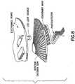
- a 5-axis Reliance robotwas used to gather data on energy dissipation during normal operation. This robot is similar to the example robot of Figure 4 .
- motor torque and motor velocity datawas downloaded each time the robot performed an extend move to pick a substrate from a non-radial station.
- the torque and velocity datawas collected for the entire move that covered the duration of the robot starting from rest and coming to rest at the end of the move. Since this particular move did not involve the motion of the Z-axis, there is no change in the gravitational potential and under ideal frictionless conditions the net energy dissipation will be zero.
- On the other handfor a real robot there is net positive energy dissipation as the robot moves between two points on the same plane. This energy dissipation is due to friction in machine components like bearings and actuators.
Landscapes
- Engineering & Computer Science (AREA)
- General Physics & Mathematics (AREA)
- Physics & Mathematics (AREA)
- Quality & Reliability (AREA)
- Theoretical Computer Science (AREA)
- Computer Hardware Design (AREA)
- Power Engineering (AREA)
- Microelectronics & Electronic Packaging (AREA)
- Manufacturing & Machinery (AREA)
- General Engineering & Computer Science (AREA)
- Condensed Matter Physics & Semiconductors (AREA)
- Automation & Control Theory (AREA)
- Testing And Monitoring For Control Systems (AREA)
- Manipulator (AREA)
- General Factory Administration (AREA)
- Debugging And Monitoring (AREA)
- Control Of Electric Motors In General (AREA)
Description
- The disclosed embodiments are directed to a condition monitoring and fault diagnosis system.
- Material damage and unscheduled downtime due to failures of robotic manipulators and other mechatronic devices used in automated manufacturing tools, such as robotized material-handling platforms for production of semiconductor devices, are common problems which often represent a significant cost burden to the end-user of the manufacturing tools.
- A number of health-monitoring and fault-diagnostic (HMFD) methods have been developed for industrial, automotive and aerospace applications. The existing systems typically implement fault detection to indicate that something is wrong in the monitored system, fault isolation to determine the exact location of the fault, i.e., the component which is faulty, and fault identification to determine the magnitude of the fault.
- The isolation and identification tasks together are often referred to as fault diagnosis. Many existing systems implement only the fault detection and isolation stages. Generally, the methods used for HMFD may be classified into two major groups: those which do not utilize a mathematical model of the system subject to monitoring and diagnostics, also referred to as the "plant," and those which do. The methods which do not use the mathematical model of the plant include physical redundancy, utilization of special sensors, limit checking, spectrum analysis, and logical reasoning.
- In the physical redundancy approach, multiple sensors are installed to measure the same physical quantity. Any serious discrepancy between the measurements indicates a sensor fault. With only two parallel sensors, fault isolation may not be possible, however, with three or more sensors, a voting.scheme may be formed which isolates the faulty sensor. Physical redundancy usually involves extra hardware cost and extra weight.
- Special sensors may be installed explicitly for detection and diagnosis. These may be limit sensors (measuring, e.g., temperature or pressure), which perform limit checking (see below) in hardware. Other special sensors may measure some fault-indicating physical quantity, such as sound, vibration, elongation, etc.
United States Patent US 6 434 512 B1 describes a diagnostics/prognostics system especially well-suited for vehicles and related method for collecting and processing data relating to a plurality of subsystems of a dynamic system includes a plurality of sensors, each sensor gathering data and generating a data signal indicative of the health of a corresponding one of the subsystems. The diagnostics/prognostics system includes a plurality of subsystem modules coupled to corresponding ones of the sensors for generating a subsystem health signal in response to corresponding ones of the data signals. A master diagnostics module is coupled to the subsystems to generate an overall system health signal in response to the subsystem health signals. The master diagnostics module includes a memory having an embedded model to facilitate generating the overall system health signal and a related trend analysis. A controller is used to generate a control signal in response to at least one of a group consisting of the subsystem health signals and the vehicle health signal, the control signal causing an operation parameter of at least one of the subsystems to change. - In a limit checking approach, widely used in practice, plant measurements are compared by computer to preset limits. Exceeding the threshold indicates a fault situation. In many systems, there are two levels of limits, the first serving for pre-warning while the second triggering an emergency reaction. Limit checking may be extended to monitoring the time-trend of selected variables. While simple and straightforward, the limit checking approach suffers from two serious drawbacks:
- (a) Since the plant variables may vary widely due to normal input variations, the test thresholds need to be set quite conservatively; and
- (b) The effect of a single component fault may propagate to many plant variables, setting off a confusing multitude of alarms and making isolation extremely difficult.
- Spectrum analysis of plant measurements may also be used for detection and isolation. Most plant variables exhibit a typical frequency spectrum under normal operating conditions; any deviation from this may be an indication of abnormality. Certain types of faults may even have their characteristic signature in the spectrum, facilitating fault isolation.
- Logical reasoning techniques form a broad class which are complementary to the methods outlined above in that they are aimed at evaluating the symptoms obtained by detection hardware and software. The simplest techniques include logical rules of the "if-symptom-and-symptom-then-conclusion" type. Each conclusion can, in turn, serve as a symptom in the next rule until the final conclusion is reached. The system may process the information presented by the detection hardware and software, or may interact with a human operator, inquiring from him or her about particular symptoms and guiding him or her through the entire logical process.
- Turning now to methods which do use a mathematical model of the plant, these model-based condition-monitoring and fault-diagnostic methods generally rely on the concept of analytical redundancy. In contrast to physical redundancy, where measurements from parallel sensors are compared to each other, sensory measurements are compared to analytically computed values of the respective variable. Such computations use present and/or previous measurements of other variables, and a mathematical plant model describing their nominal relationship to the measured variable. The idea can be extended to the comparison of two analytically generated quantities, obtained from different sets of variables. In either case, the resulting differences, called residuals, are indicative of faults in the system. Another class of model-based methods relies directly on parameter estimation.
- The generation of residuals needs to be followed by residual evaluation in order to arrive at detection and isolation decisions. Because of the presence of noise and model errors, the residuals are never zero, even if there is no fault. Therefore the detection decision requires testing the residuals against thresholds, which may be obtained empirically or by theoretical considerations. To facilitate fault isolation, the residual generators are usually designed for isolation enhanced residuals, exhibiting structural or directional properties. The isolation decisions then can be obtained in a structural (Boolean) or directional (geometric) framework, with or without the inclusion of statistical elements.
- There are four somewhat overlapping approaches to residual generation in model-based condition monitoring and fault diagnostics: Kalman filter, diagnostic observers, parameter estimation and parity relations.
- The prediction error of a Kalman filter can be used as a fault detection residual. Its mean is zero if there is no fault (and disturbance) and becomes nonzero in the presence of faults. Since the innovation sequence is white, statistical tests are relatively easy to construct. However, fault isolation is somewhat awkward with the Kalman filter; one needs to run a bank of "matched filters", one for each suspected fault and for each possible arrival time, and check which filter output can be matched with the actual observations.
- Diagnostic observer innovations also qualify as fault detection residuals. "Unknown input" design techniques may be used to decouple the residuals from a limited number of disturbances. The residual sequence is colored, which makes statistical testing somewhat complicated. The freedom in the design of the observer can be utilized to enhance the residuals for isolation. The dynamics of the fault response can be controlled within certain limits by placing the poles of the observer.
- Parameter estimation is a natural approach to the detection and isolation of parametric (multiplicative) faults. A reference model is obtained by first identifying the plant in a fault-free situation. Then the parameters are repeatedly re-identified on-line. Deviations from the reference model serve as a basis for detection and isolation. Parameter estimation may be more reliable than analytical redundancy methods, but it is also more demanding in terms of on-line computation and input excitation requirements.
- Parity (consistency) relations are rearranged direct input-output model equations subjected to a linear dynamic transformation. The transformed residuals serve for detection and isolation. The residual sequence is colored, just like in the case of observers. The design freedom provided by the transformation can be used for disturbance decoupling and fault isolation enhancement. Also, the dynamics of the response can be assigned within the limits posed by the requirements of causality and stability.
- The health-monitoring and fault-diagnostic methods directly applicable to semiconductor manufacturing systems have generally been limited to a small number of faults, for example, those associated with joint backlash. This may be because additional restrictions, such as variability of faults, unsteady and non-uniform operating conditions and limited availability of component characteristics collected over time exist in this area. The analytical methods described above have been primarily applied to systems that are defined by linear equations and are not directly applicable to systems whose dynamics are non-linear. There are, however, a few examples of robotic system applications using parameter identification, the Kalman filter approach, the use of multiple linear neural network models for robot fault diagnosis, and the use of a diagnostic observer for detecting faults in a simulated electro-hydraulic actuator.
- It would be advantageous to provide an improved system for monitoring conditions and diagnosing faults.
- The present invention provides a system for condition monitoring and fault diagnosis of a machine according to
claim 1. - The present invention further provides a method according to
claim 5. Preferred embodiments are defined in dependent claims. The invention is set out in the appended set of claims. The embodiments and/or examples of the following description which are not covered by the appended claims are considered as not being part of the present invention. - The foregoing aspects and other features of the presently disclosed embodiments are explained in the following description, taken in connection with the accompanying drawings, wherein:
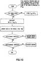
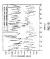
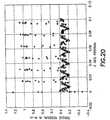
Figure 1 shows a condition-monitoring and fault-diagnostic system according to the disclosed embodiments;Figure 2 shows an exemplary function controller for implementing the disclosed embodiments;Figure 3 shows an automated material-handling platform for production of semiconductor devices;Figure 4 shows a five-axis direct-drive robotic manipulator;Figure 5 shows a vacuum-actuated edge-contact gripper;Figure 6 shows a surface-contact suction gripper;Figure 7 shows an end-effector with one or more mapper sensors;Figure 8 shows an incremental rotary optical encoder;Figure 9 shows an absolute rotary optical encoder;Figure 10 shows a method for incremental encoder data integrity checking;Figure 11 shows a method for absolute encoder data integrity checking;Figure 12 shows a plot of the energy dissipation over successive extend moves to an off-center station for a robot in a normal condition;Figure 13 compares the energy dissipation values for successive extend moves for different phase angles;Figure 14 shows the energy dissipation data for two different motor phase angles in the same robot after a 30-day interval;Figure 15 compares the energy dissipation in anormal robot 30 days apart;Figure 16 shows a traverser motor current for two different phase angles over time;Figure 17 shows the variation of motor current residual with respect to nominal current;Figure 18 shows the variation of torque residue with respect to velocity;Figure 19 shows a comparison of Z motor torque with and without brake drag;Figure 20 shows a diagram of residual of Z motor torque; andFigure 21 shows a comparison of model prediction with actual torque values.Figure 1 shows a block diagram of asystem 100 suitable for monitoring conditions and for diagnosing faults of a machine as disclosed herein. Although the disclosed embodiments are described with reference to the drawings, it should be understood that they may be implemented in many alternate forms. In addition, any suitable types, forms, or physical shapes of elements or materials could be used.- The disclosed embodiments are directed to a system and method for assessing the condition of system components, referred to as health monitoring, and performing fault diagnosis. As a result of the health monitoring and fault diagnosis functions, the system may also schedule predictive maintenance or service as required, and adjust system processes to maintain operations until maintenance or service may be performed.
- Condition assessment refers to measuring characteristics, performance, outputs or other indicators of the operation of a system component to determine its condition. Fault diagnosis refers to the ability to identify a component fault from the indicators of operation, other component characteristics, or from system operations. Automated fault diagnosis may complement or relieve an operator from fault classification and troubleshooting tasks, including diagnostic error codes and interactive diagnostic screens.
- Predictive maintenance refers to tasks performed to maintain proper operation while services refers to tasks performed on a non-operational component to restore it to operational status
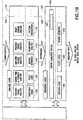
- As shown in
Figure 1 , the present system may include four functions: adata collection function 105, apre-processing function 110, ananalysis function 115, and areasoning function 120. In addition, the operation of thefunctions 105 110, 115, 120 may be coordinated by a health-monitoring and fault-diagnostic manager 130. Each of the fourfunctions manager 130 may be implemented in software, hardware, or any combination of both. - The software implemented portions of the
system 100 may reside on one or more program storage devices encoded with a computer program, for example, machine readable program source code, which is adapted to cause one or more computers to perform the operations described in the disclosed embodiments. The program storage devices may include magnetic media such as a tape, disk, or computer hard drive, optical media, semiconductor media, or any other device suitable for storing a computer program. - It is a feature of the disclosed embodiments that the data collection function acquires time histories of selected variables during operation of the machine being monitored, the pre-processing function calculates specific characteristics of the acquired time histories, the analysis function evaluates characteristics of individual components with which the variables are associated and produces one or more hypotheses about the condition of each of the components, and the reasoning function derives an overall assessment of the machine, including the condition of the individual components of the machine and the degree of confidence that the machine is in good operating condition. For purposes of the disclosed embodiments, a machine may be an optical, mechanical, electrical, or electromechanical device, a computer software program, or any combination of the aforementioned items and may include any entity whose operation may be monitored.
- It is a further feature of the disclosed embodiments that the system may be implemented in a hierarchically distributed manner. For example, multiple instances of each function may reside in, or be associated with, progressively higher level controllers within the machine such that the data required for health monitoring and fault diagnostic purposes are used at the level where sufficient intelligence to process the data is present.
- As a further example, the machine may be a semiconductor production system with a master controller overseeing an atmospheric section with multiple robotic manipulators. Each manipulator may have a number of motors. An instance of the data collection function may reside in each motor controller, and an instance of the pre-processing function may reside in each robot controller that controls a group of motor controllers. The controller for the atmospheric section may hold an instance of the analysis function, and the master controller may hold an instance of the reasoning function. This hierarchical approach reduces network traffic by eliminating the need for real-time streaming of individual data points from each individual device controller upward through the system architecture to the master controller. This approach is also advantageous because it eliminates the need for upper level controllers to configure data collection processes for a variety of devices, each with different types of variables to monitor requiring different processing algorithms.
- It should be noted that the hierarchical or distributed approach is different from existing centralized trends referred to as e-diagnostics. In e-diagnostics, all of the data necessary for health monitoring and fault diagnostics are transmitted to a high-level controller, such as the master controller mentioned above, and analyzed at this high level. This approach requires extremely high volumes of data to propagate from the low-level controllers all the way to the high-level controller, often in real time. In addition, the high-level controller needs to store properties of all of the components of the robotized system, such as motor parameters or kinematic and dynamic models of the robots, to be able to process the collected data.
- Returning to
Figure 1 , each function generally receives data from a lower level, processes the data and passes the processed data to the next function or ultimately to a user or higher level system. Figure 2 shows anexemplary function controller 200 within which each of the fourfunctions manager 130 may be put into practice. Each of the functions may operate in a hardware or software function controller that pre-exists withinsystem 100. For example, each function may reside in a component controller, a controller that directs the operation of a number of components, a controller that controls a subsystem, or a system controller. Each function may also be implemented in dedicated hardware or software.- The
function controller 200 may generally include aprocessor 205, read onlymemory 210,random access memory 215,program storage 220, auser interface 225, and anetwork interface 230. Processor 205 may include an onboard cache 235 and is generally operable to read information and programs from a computer program product, for example, a computer useable medium, such as onboard cache 235, read onlymemory 210,random access memory 215, andprogram storage 220.- Upon power up,
processor 205 may begin operating programs found in read onlymemory 210 and after initialization, may load instructions fromprogram storage 220 torandom access memory 215 and operate under control of those programs. Frequently used instructions may be temporarily stored in onboard cache 235. Both read onlymemory 210 andrandom access memory 215 may utilize semiconductor technology or any other appropriate materials and techniques.Program storage 220 may include a diskette, a computer hard drive, a compact disk (CD), a digital versatile disk (DVD), an optical disk, a chip, a semiconductor, or any other device capable of storing programs in the form of computer readable code. - On
board cache 235, read onlymemory 210,random access memory 215, andprogram storage 220, either individually or in any combination may include operating system programs. The operating system programs may be supplemented with an optional real time operating system to improve the quality of data provided by thefunction controller 200 and to allow thefunction controller 200 to provide a guaranteed response time. - In particular, on
board cache 235, read onlymemory 210,random access memory 215, andprogram storage 220, either individually or in any combination may include programs for causing theprocessor 205 to perform the data collection, pre-processing, analysis, reasoning functions, and the operation of the health-monitoring and fault-diagnostic manager described below. In addition, onboard cache 235, read onlymemory 210,random access memory 215, andprogram storage 220 may be loaded with new or upgraded programs, for example, byprocessor 205 throughnetwork interface 230. Network interface 230 may be generally adapted to provide an interface between thefunction controller 200 and other function controllers, system controllers, or other systems.Network interface 230 may operate to receive data from one or more additional function controllers and to convey data to the same or other function controllers.Network interface 230 may also provide an interface to a global diagnostic system that may provide remote monitoring and diagnostic services.Communication network 120 may include the Public Switched Telephone Network (PSTN), the Internet, a wireless network, a wired network, a Local Area Network (LAN), a Wide Area Network (WAN), a virtual private network (VPN) etc., and may further include other types of networks including X.25, TCP/IP, ATM, etc. In one embodiment,communication network 120 may be an IEEE 1349 network, also referred to as a "Firewire" network.- The
function controller 200 may include auser interface 225 with adisplay 240 and an input device such as akeyboard 255 ormouse 245. The user interface may be operated by auser interface controller 250 under control ofprocessor 205 and may provide a user with a graphical user interface to visualize the results of the health monitoring and fault diagnostics. The user interface may also be used to guide service personnel through troubleshooting routines or repair processes. In addition, the user interface controller may also provide a connection orinterface 255 for communicating with other function controllers, an external network, another control system, or a host computer. - Returning to
Figure 1 , thedata collection function 105 operates to acquire time histories of selected variables relating to the operation of a device being monitored. A time history refers to a collection of values for a particular variable or group of variables over time. In addition to the elements of thefunction controller 200 described above, thedata collection function 105 includes one ormore buffers 125 for collecting the values of the selected variables. Thedata collection function 105 also includes programs andcircuitry 135 for specifying the device signals and variables to be recorded, setting the sampling period for data recording, setting the trigger mode for data recording (e.g., on event, on start of move, on end of move, when above threshold, when below threshold, with delay), setting the number of samples to be recorded, and setting the mechanism to stop data recording (e.g., when specified, on event, on end of move, on error, with delay). - The
pre-processing function 115 determines specified characteristics of the acquired time histories. For example, a specified characteristic may include an average signal value or a maximum power consumption. Exemplary calculations performed by the pre-processing function may include simple mathematical operations such as add, subtract, multiply, divide, calculation of maximum, minimum and average values, Fourier transformation, wavelet transformation, and evaluation of various mathematical models. In addition to the elements of thefunction controller 200 described above, thepre-processing function 115 includes programs andcircuitry 140 for receiving the time histories from thedata collection function 105 and for performing the simple calculations required. - The
analysis function 120 includes algorithms for analyzing the characteristics of a number of individual components, and for producing one or more hypotheses about the condition of each of the components. For example, theanalysis function 120 may includevarious analysis algorithms 145 specifically tailored for the type of characteristics being examined, such as voltage, current, torque, signal variation, etc. As a further example, when implemented in a robotized manufacturing tool, theanalysis function 120 may include algorithms for encoder signal analysis, motor PWM and current analysis, power supply voltage analysis, tracking error analysis and robot torque analysis. The algorithms may have access to and may utilize alibrary 150 of various analysis methods includingsimple threshold rules 155,fuzzy logic 160,neural networks 165,regression analysis 170, andpattern recognition techniques 175. - The
reasoning function 125 derives, based on the hypotheses obtained from theanalysis function 120, the final response of thesystem 100, including the condition of the individual components and the degree of confidence that one or more monitored devices are in good-health condition. Thereasoning function 125 may include an expertdiagnostic system 180 which may include, for example, aknowledge base 197 having rule-based information relating to a given set of parameters for system components and sub-systems. The expertdiagnostic system 180 may utilize various methods based on, for instance,Boolean logic 185,fuzzy logic 190, orneural networks 195. - The functions of the
present system 100 are coordinated by a health-monitoring and fault-diagnostic (HMFD)manager 130. Themanager 130 may configure and initialize each of the data collection, pre-processing analysis, and reasoning functions to operate for a number of given monitored devices. - For example, the
manager 130 may initialize thedata collection function 105 with a number of variables to record, along with a number of samples to record and triggering information in order for the pre-processing function to produce one or more time histories. Themanager 130 may coordinate the operations of thedata collection function 105 in any of a number of collection modes, for example, data collection may take place at all times during normal operation of the device being monitored, or it may occur when the device performs certain pre-determined operations which are part of its regular operation which is convenient when comparing current signals with a normal baseline profile. Alternately, data collection may be triggered at regular intervals as the device being monitored performs a set of template operations pre-designed specifically for health-monitoring and fault-diagnostic purposes. In one embodiment, the manager may limit the amount of data recorded during data collection operations to a minimum amount for detecting deteriorating health or for diagnosing faults of the monitored device. - In some embodiments, when a potential problem is detected, the
manager 130 may initiate collection of additional data by thedata collection function 105 for accurate fault diagnosis. Themanager 130 may also initiate a template sequence which was pre-designed specifically for health-monitoring and fault-diagnostic purposes. This sequence may be specific to a certain mode of failure or a category of modes of failure. - The
manager 130 may operate to initialize thepre-processing function 110 by specifying the type of pre-processing that will occur when the time histories are sent to thepre-processing function 110. In addition, themanager 130 may preset theanalysis function 115 with the types of analysis to be performed on the data for the various data characteristics received from thepre-processing function 110. Themanager 130 may also pre-load thelibrary 150 and specify the methods used in the different analyses. Furthermore, themanager 130 may trigger decision making in thereasoning function 125 when the analyses are complete. - As mentioned above, the
system 100 provides at least two distinct functions: health monitoring and fault diagnostics. The purpose of health monitoring is to perform condition assessment of individual components of the robotized tool, and report a service request when a problematic condition of any of the components is identified. This information can be used for preventive maintenance, reducing material damage and unscheduled downtime due to unforeseen failures. Additionally, the present system can adjust the operation of the robotized tool to keep the tool functional to the extent possible, to reduce the effect of the progressing failure on key performance characteristics, and/or to increase the time to a fatal failure so that the tool can run till it can be serviced, e.g., till the next schedule maintenance takes place. - The purpose of fault diagnostics, on the other hand, is to complement or relieve an operator from fault classification and troubleshooting tasks, including diagnostic error codes and interactive diagnostic screens, thus improving responsiveness, quality and cost of service.
- An automated material-handling platform for production of semiconductor devices will be used as an exemplary embodiment in which the present condition-monitoring and fault-diagnostic system may be practiced.
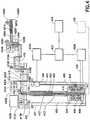
- An exemplary material-handling platform for production of semiconductor devices is depicted diagrammatically in
Figure 3 , with explanatory notes for major components being listed in Table 1.Table 1: Explanatory notes for the automated material-handling platform of Figure 3. Number Description 301 Atmospheric section 302 Vacuum section 303 Process module 304 Enclosure 305 Loadport 306 Atmospheric robotic manipulator 307 Substrate aligner 308 Fan- filter unit 309 Vacuum chamber 310 Load- lock 311 Vacuum robotic manipulator 312 Vacuum pump 313 Slit valve 314 Tool controller 315 Atmospheric section controller 316 Vacuum section controller 317 Process controller 318 Loadport controller 319 Atmospheric robot controller 320 Aligner controller 321 Fan- filter unit controller 322 Motor controller 323 Vacuum robot controller - The platform has an
atmospheric section 301,vacuum section 302 and one ormultiple process modules 303. - The
atmospheric section 301 may include anenclosure 304, one ormultiple loadports 305, one or multiple robotic manipulators 306, one ormultiple substrate aligners 307 and a fan-filter unit 308. It may also include one or more ionization units (not shown). The vacuum section may include avacuum chamber 309, one or multiple load-locks 310, one or multiplerobotic manipulators 311, one ormultiple vacuum pumps 312 and a plurality ofslit valves 313, which are typically located at the interface of theatmospheric section 301 with the load-locks 310, between the load-locks 310 and thevacuum chamber 309, and between thevacuum chamber 309 and theprocess module 303. - The operation of the platform is coordinated by the
tool controller 314, which supervises theatmospheric section controller 315,vacuum section controller 316 and one ormultiple process controllers 317. Theatmospheric section controller 315 is in charge of one or multipleloadport controllers 318, one or multipleatmospheric robot controllers 319, one ormultiple aligner controllers 320 and a fan-filter unit controller 321. Each of theloadport controllers 318,atmospheric robot controllers 319 andaligner controllers 320 is in turn in charge of one ormultiple motor controllers 322. Thevacuum section controller 316 is in charge of one or multiplevacuum robot controllers 323, controls thevacuum pump 312 and operates theslit valves 313. The role of theprocess controller 317 depends on the operations performed in theprocess modules 303. - In some cases, it may be practical to combine two or more layers of control into a single controller. For instance, the atmospheric robot controller 119 and the corresponding motor controllers 122 may be combined in a single centralized robot controller, or the
atmospheric section controller 115 can be combined with the atmospheric robot controller 119 to eliminate the need for two separate controller units. - A five-axis direct-drive robotic manipulator may be employed in the platform of
Figure 3 . A simplified schematic of such a robotic manipulator is provided inFigure 4 . Explanatory notes for major components are listed in Table 2.Table 2: Explanatory notes for robotic manipulator of Figure 4. Number Description 401 Robot frame 402 Mounting flange 403 Vertical rail 404 Linear bearing 405 Carriage 406 Vertical drive motor 407 Ball screw 408 Motor 1 (driving link 1) 409 Motor 2 (driving link 2) 410 Encoder 1 (coupled to motor 1) 411 Encoder 2 (coupled to motor 2) 412 Outer shaft 413 Inner shaft 414 Link 1 (upper arm) 415 Belt driving link 2416 Link 2 (forearm) 417A Motor A (driving end-effector A) 417B Motor B (driving end-effector B) 418A First stage of belt drive A 418B First stage of belt drive B 419A Second stage of belt drive A 419B Second stage of belt drive B 420A End-effector A (upper end-effector) 420B End-effector B (lower end-effector) 421A, 421B Payload on end-effectors A and B 422 Master controller 423A, 423B, 423C Motor controllers 424A, 424B Electronic units for end-effectors A and B 425 Communications network 426 Slip- ring 428A, 428B Mapper sensors 429 Power supply 430 Vacuum pump 431A, 431B Valves 432A, 432B Pressure sensors 433, 434A, 434B Lip- seals 435 Brake - Referring to
Figure 4 , the robotic manipulator is built around an opencylindrical frame 401 suspended from acircular mounting flange 402. Theframe 401 incorporates avertical rail 403 withlinear bearing 404 to provide guidance to acarriage 405 driven by abrushless DC motor 406 via a ball-screw mechanism 407. Thecarriage 405 houses a pair of coaxialbrushless DC motors optical encoders 410, 411. Theupper motor 408 drives a hollowouter shaft 412 connected to thefirst link 414 of the robot arm. Thelower motor 409 is connected to a coaxialinner shaft 413 which is coupled via abelt drive 415 to thesecond link 416. Thefirst link 414 houses abrushless DC motor 417A which drives through a two-stage belt arrangement effector 420A. AnotherDC brushless motor 417B and a two-stage belt drive effector 420B. Each of thestages Substrates effectors Figures 5 and 6 for exemplary gripper designs. - The
first link 414,second link 416, upper end-effector 420A and lower end-effector 42GB are also referred to as the upper arm, forearm, end-effector A and end-effector B, respectively, throughout the text. The points A, B and C indicate revolute couplings which are referred to as the shoulder, elbow and wrist joints, respectively. Point D denotes a reference point which indicates the desired location of the center of the substrate on the corresponding end-effector. - The control system of the example robotic manipulator may be a distributed type. It comprises a
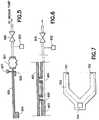
power supply 429,master controller 422 andmotor controllers master controller 422 is responsible for supervisory tasks and trajectory planning. Each of themotor controllers Figure 4 , thecontroller 423A controlsmotors controller 423B controlsmotors controller 423C controlsmotor 406. In addition to executing the feedback loops, the motor controllers also collect data such as motor current, motor position and motor velocity, and stream the data to the master controller. Themotor controllers highspeed communication network 425. Since the joint A is an infinite rotation joint, thecommunication network 425 is routed through a slip-ring 426. Additionalelectronic units effectors Figure 5 shows a schematic of a vacuum-actuated edge-contact gripper system. It includes abellows 501 attached to a vacuum line on one end and aplunger 503 attached to the other end. In the absence of vacuum, the spring loaded plunger pushes thesubstrate 505 against thestationary stops 504 and holds it in place. In the presence of vacuum, the plunger is retracted, which releases its hold on the substrate. The position of theflag 507 is used to determine the position of the plunger which, in turn, indicates one of the following three states: unclamped (plunger 503 retracted), properly clamped (plunger 503 partially extended) and clamping failure (plunger 503 fully extended). The gripper is operated by opening and closing a vacuum valve, such as 431A or 431B inFigure 4 . The vacuum pressure may be measured by a pressure sensor, such as 432A or 432B inFigure 4 .Figure 6 shows a cross-sectional view of a surface-contact suction gripper. The robot end-effector 603 has two ormore orifices 605 that are connected to avacuum line 604. In the presence of vacuum, the substrate 601 is pulled toward the end-effector 403 and held in place by the means of friction. The gripper action is initiated by a vacuum valve, such as 431A or 431B inFigure 4 . The presence or absence of the substrate 601 on the end-effector 603 can be determined by a pressure sensor, such as 432A or 432B inFigure 4 . Thepressure sensor - As indicated above, both types of grippers require a vacuum valve, such as
valves Figure 4 , that opens or closes the vacuum line. The vacuum valves may be controlled either by the master ormotor controllers sensors - The use of vacuum for the vacuum-actuated edge-contact gripper or surface-contact suction gripper requires a vacuum line to be run through the joints, connecting an external vacuum source, such as a vacuum pump, to the end effector. Since joints A and C are continuous rotation joint, lip seals 433, 434A and 434B are used to transmit vacuum across the joints A and C.
- In some cases, each of the robot end-
effectors Figure 5 and the surface-contact suction gripper ofFigure 6 , or can serve as the only means of substrate presence sensing, such as when the substrate is held on the end-effector passively, e.g., by frictional forces between the substrate and the end-effector. - Each of the end-
effectors Figure 4 . Each mapper sensor comprises alight emitter 701 and alight receiver 702 as shown inFigure 7 . As the robot scans a substrate carrier, the binary output of the light detector changes state and is read by the controller which determines the presence or absence of a wafer in each of the slots in the substrate carrier. The controller also records robot axes positions each time the binary output changes state and uses this information to detect "cross-slotted" wafers and "doubly-placed" wafers in the load port. - The motor that controls the vertical motion of the robot (
motor 406 inFigure 4 ) is equipped with a solenoid actuatedbrake 435. In the absence of motor torque, the brake engages in order to prevent a free fall of the robot. The vertical axis may also be equipped with over-travel sensors, such as limit switched, that detect when thecarriage 405 exceeds the allowable range of vertical motion. - The robotic manipulator may include additional components, such as cooling fans to remove heat generate by motors and electronics. In some applications, the robotic manipulator may be installed on a horizontal traverser.
- Since optical encoders, such as 410 and 411 in
Figure 4 , are critical for proper operation of the robot and represent a valuable source of information for health monitoring and fault diagnostics, more detailed description of their functionality should be provided. A rotary optical encoder is a device that converts angular motion into a digital output easily interfaced with the controller. There are two types of optical encoders: incremental and absolute. - A rotary incremental optical encoder (
Figure 8 ) may have the following components: light source, rotating encoder disk, stationary mask, photodetector, and electronics to amplify and square the output signals from the photodetector. As the encoder disk rotates in front of the mask, it shutters the light from the light source. The light that passes through mask is received by the photodetector which produces pulses in the form of a quasi-sine wave output. The encoder electronics convert this output into a square wave form, ready for transmission to a counter. The number of counts is directly proportional to the angular position of the encoder disk. Many encoders also include a single zero mark which provides one pulse every mechanical rotation for reference, e.g., to determine a home position. - In principle, rotary absolute optical encoders (
Figure 9 ) are similar to incremental encoders in that a rotating disk interrupts light between a source and photodetector to produce an output signal. However, as opposed to a single track incremental encoder, an absolute encoder disk features several concentric tracks, each having a pattern of transparent and opaque segments. These independent tracks provide a unique combination for each resolvable position. Since every position of an absolute encoder is unique, absolute encoders do not loose position when power is removed, and it is not necessary to initialize the system by returning to a zero or home position. In most applications, the absolute position is determined only when the device is turned on. From that point on, to make it possible to obtain high resolution at fast speeds, the position is determined in an incremental manner based on analog sin/cos signals. - The example robotic manipulator is a complex mechatronic system with numerous components that may exhibit failures. These components include the power supply, motors, encoders, belts, bearings, ball-screws, brakes, vacuum system components, communication system components, master controller, motor controllers, and cooling fans.
- The present condition-monitoring and fault-diagnostic system utilizes time histories of selected signals to perform condition assessment of individual system components. The signals may be obtained from sources that already exist in the tool, or may come from additional sensors added specifically for health-monitoring and fault-diagnostic purposes.
- Generally, it is desirable to extract as much information as possible from the sources that already exist in the tool, i.e., those sources that are used by the robot and other devices to achieve the desired functionality. This is because additional sensors lead to increased complexity and cost. In some cases, however, it may be preferable to add sensors specifically for health-monitoring and fault-diagnostic purposes because extracting all of the information from the existing signals is not possible or requires complex algorithms, which need to run on more powerful and expensive processors, and may be costly to develop and support.
- Typically, the following signals exist in a robotized manufacturing tool, and can be made available for condition monitoring and fault diagnostics:
- (a) Motor PWM duty: PWM duty of a motor is the percentage of input voltage that is supplied to each motor phase at any given time. The duty cycle at each of the motor phases is available to the health-monitoring and fault-diagnostic system.
- (b) Motor current: Motor current represents the current flowing through each of the three phases of each of the motors. The motor current may be obtained as an absolute value or as a percentage of the maximum current. If obtained as an absolute value it has units of Amps. Motor current values can in turn be used to compute motor torques using the motor torque-current relationships.
- (c) Actual position, velocity and acceleration: These are the position, velocity and acceleration of each of the motor axes. For rotational axes, the position, velocity and acceleration values are in units ofdegrees, degrees/sec and degress/sq.sec respectively. For translational axes, the position, velocity and acceleration values are in units ofmm, mm/sec andmm/sq.sec respectively.
- (d) Desired position, velocity and acceleration: These are the position, velocity and acceleration values that the controller commands the motors to have. These properties have similar units as the actual position, velocity and acceleration above.
- (e) Position and velocity tracking error: These are the differences between the respective desired and actual values. These properties have similar units as the actual position, velocity and acceleration above.
- (f) Settling time: This is the time it takes for the position and velocity tracking errors to settle within specified windows at the end of motion.
- (g) Encoder analog and absolute position outputs: The motor position is determined by the encoders which output two types of signals - analog signals and absolute position signals. Analog signals are sine and cosine signals in units of mVolts. Absolute position signals are non-volatile integer values that indicate the number of analog sine cycles or an integer multiple of analog sine cycles that have gone by. Typically, digital outputs are read on power up and thereafter the axis position is determined solely from the analog signals.
- (h) Gripper state: This is the state of the gripper - open or closed. In the case of a vacuum-actuated edge-contact gripper, it is the blocked/unblocked state of one or more sensors.
- (i) Vacuum system pressure: This is the vacuum level measured by a vacuum sensor. This is an analog sensor whose output is digitized by an analog-to-digital converter. In the case of a suction gripper, the vacuum level indicates whether the wafer has been gripped.
- (j) Substrate-presence sensor state: In a passive grip end effector, the wafer presence sensor output is a binary output. In a vacuum-actuated edge-contact grip end effector, the wafer presence is determined from the output state of two or more sensors each of which is binary.
- (k) Mapper sensor state: This is the state of the mapper sensor - blocked or unblocked at any given instance.
- (l) Mapper/Aligner detector light intensity: This is a measure of the intensity of the light detected by the light detector (503 in
Figure 5 ). This signal is typically available as an integer value (that may have a range of 0 - 1024 as an example). - (m) Mapper sensor position capture data: This is the array of robot axis position values at which the mapper sensor changes state.
- (n) Vacuum valve state: This is the commanded state of the vacuum valve. It specifies if the solenoid that operates the vacuum valve is supposed to be energized.
- (o) Voltage at fuse output terminals: The voltages at the output terminals of each of the fuses in the motor control circuitry is monitored. A blown fuse results in low output terminal voltage.
- (p) Substrate alignment data: These are the substrate eccentricity vector and angular orientation of the alignment fiducial of a substrate reported by the aligner.
- (q) Position data at transition of external substrate sensors: In some cases, the atmospheric and vacuum sections of the tool may be equipped with optical sensors which detect the leading and trailing edges of a substrate carried by the robot. The robot position data corresponding to these events are used for on-the-fly recognition of the eccentricity of the substrate on the robot end-effector.
- (r) Substrate cycle time: This is the time it takes for a single substrate to be processed by the tool, typically measured under steady flow conditions.
- (s) Mini-environment pressure: This is the pressure measured by a pressure sensor in the atmospheric section of the tool.
- As mentioned above, it is often desirable to complement the signals that are already available in the tool by sources of information added specifically for the purpose of health monitoring and fault diagnostics. These sources may include the following:
- (a) Direct Measurement of Motor torque : Motor torques can be measured directly instead of being estimated from motor current. This is done by using force or torque gauges to measure the external force/torque required to hold an energized motor stationary.
- (b) Motor temperature: This refers to the temperature of the motor and is read by a temperature sensor that is mounted on the motor. Temperature may be available in units of degree C.
- (c) Over-travel sensors: These are sensors, such as limit switches, that indicate if the motion axis that the sensors are associated with exceeded its allowable range of travel.
- (d) Acoustic and vibration sensor data: This represents electrical signals obtained from microphones and accelerometers placed at various points on the robot or in the vicinity of the robot.
- (e) Infrared sensor data: This represents temperature readings obtained from infrared sensors placed at various points in the tool to monitor temperature variation.
- (f) Power consumption: The motor currents, velocities and duty cycle values can be used to compute the electrical power consumed by each motor at any given time.
- (g) Deflection: This represents electrical signals obtained from strain-gauges placed at various points on the robot to measure deflection.
- (h) Belt tension: The output of a force sensing device attached to the belt tensioner serves as a measure of belt tension. It has units of Newtons.
- (i) Duration of operation of cooling fans: Cooling fans may either be continuously operating or thermostat controlled. A useful indicator of heat dissipation from the robot is the duration of operation of thermostat controlled cooling fans.
- (j) Electrostatic charge of substrate: Among other methods, the level of the substrate charge can be determined through a controlled discharge of the substrate.
- (k) Position data at transition of external sensors: Additional external sensors may be used to detect edges of moving substrates and robot components to allow the controller to capture the corresponding robot position data and use the resulting information, e.g., for robot and substrate repeatability checking.
- (l) Video images: These represent video images obtained from video cameras mounted either stationary at specific locations that the robot reaches periodically, or cameras carried by the robot. In the latter case, the cameras may point either at the end-effector or at stationary markers.
- (m) Plenum pressure: This is the pressure measured by a pressure sensor on the input side of the filter in the fan-filter unit.
- Component failures can be categorized broadly into two different types - "chronic" faults that develop gradually and "acute" faults that occur instantly. Faults of the first kind can be detected by a condition monitoring system at their early stages of development. Early detection and repair will help avoid unexpected failure during operation. On the other hand, faults of the second type do not lend themselves to early detection. However, a fault diagnostics system can help diagnose them when they occur and therefore shorten the time to bring the machinery back into operation. The different types of faults that can occur are listed below and summarized in Table 3.
Table 3: Example modes of failure and their symptoms Component Mode of failure Sudden/gradual Measurable symptom Motor Weakening or disintegration of magnets Gradual Overall increase in motor winding currents; Overall increase in motor temperature; Increase in power consumption; Increase in energy dissipation; Longer duration of operation of cooling fans Slipping or misalignment of stator Gradual Increase in motor winding currents; Overall increase in motor temperature; Increase in power consumption; Increase in energy dissipation; Longer duration of operation of cooling fans High connector resistance Gradual Overall increase in PWM duty; Overall increase in power consumption; Increase in energy dissipation Burnt Motor Phase Abrupt Abrupt drop in motor current in the phase winding Blown fuse Abrupt Abrupt drop in voltage at the output terminal of the fuse Encoder Optical disk contamination Gradual Attenuation of sine signal amplitude Read-head misalignment Gradual or abrupt Phase distortion of sin/cos signals; Attenuation of signal amplitude Electrical noise in encoder wiring Gradual or abrupt Decrease in signal-to-noise ratio of sin/cos signals Missed counts Gradual or abrupt Differences between absolute axis position and position computed from incrementing encoder counts Belt Tension below specification Gradual Oscillatory tracking errors; Lower force measurement at the belt tensioner; Decrease in resonance frequency corresponding to belt tension Tension above specification Abrupt Higher force measurement at the belt tensioner Increase in resonance frequency Rubbing against a component Gradual or abrupt Higher motor currents; Higher power consumption; Higher energy dissipation; Increase in motor temperature; Longer duration of operation of cooling fans; Shifts in power spectrum of acoustic energy dissipation Belts slipping Gradual or abrupt Significant shift in position measured by external sensors such as video cameras and over-travel sensors; Increase in tracking errors. Vacuum system Leak Gradual or abrupt Lower vacuum pressure measurement; Increase in pressure transition time. This results in an increase in grip actuation time in the case of a surface contact vacuum gripper and an increase in grip release time in the case of a vacuum actuated edge contact gripper; Failure to grip, in the case of a surface contact vacuum gripper and a failure to ungrip in the case of a vacuum operated edge contact gripper Obstruction between vacuum sensor and actuator Gradual or sudden Decrease in pressure transition time; Increase in vacuum pressure required to accomplish a grip actuation in the case of a surface contact vacuum gripper and a grip release in the case of a vacuum actuated edge contact gripper Failure to grip, in the case of a surface contact vacuum gripper and a failure to ungrip in the case of a vacuum operated edge contact gripper Obstruction between vacuum valve and vacuum sensor Gradual or sudden Low vacuum pressure detected by the vacuum sensor; Increase in pressure transition time. This results in an increase in grip actuation time in the case of a surface contact vacuum gripper and an increase in grip release time in the case of a vacuum actuated edge contact gripper; Failure to grip, in the case of a surface contact vacuum gripper and a failure to ungrip in the case of a vacuum operated edge contact gripper Vacuum-actuated edge-contact gripper Jammed Plunger Gradual or abrupt Increase in vacuum pressure for grip actuation; Failure to release grip Broken spring Abrupt Gripper is always in released state Bearing/bal 1-screw Binding Gradual Increase in motor current; Increase in power consumption; Increase in energy dissipation; Increase in tracking error; Increase in motor temperature Play Gradual Higher position errors recorded by external position sensors such as over-travel sensors and video imaging cameras; If large enough to cause noticeable motor stator misalignment: [???] Increase in motor winding currents; Overall increase in motor temperature; Increase in power consumption; Increase in energy dissipation; Longer duration of operation of cooling fans ; Communication system Slipring failure Gradual Increase in error rates in the initial stages of failure; Master controller does not receive status updates from one or more motor controllers in the final stages Failure of communication chips on the motor controllers Abrupt Master controller does not receive status updates from one or more motor controllers Failure of communication chips on the master controller Abrupt The motor controllers do not receive motion information from the master controller. Break in communication link between two adjacent motor controllers Abrupt Decrease in the number of nodes in the network Substrate mapper Noise in sensor electrical output Gradual Multiple block/unblock transitions of the mapper digital output as it passes through each substrate; Odd number of state transitions Light intensity fluctuation Gradual Shift or absence of block/unblock transitions Faulty sensor Abrupt Absence of block/unblock transitions Brakes Brake partially released or not released Gradual Position dependent increase in motor current; Overall increase in power consumption; Increase in energy dissipation; Change in spectrum of the measured acoustic signal Abrupt Increase in motor current; Overall increase in power consumption; Increase in energy dissipation; Change in spectrum of the measured acoustic signal External Obstruction Abrupt Rapid increase in motor current; Rapid increase in position and velocity error Cooling fans Stop functioning Abrupt Increase in overall system temperature Power supply No voltage (e.g. , blown fuse) Abrupt Zero motor current; Voltage sensor in motor controller indicates low bus voltage error; Sudden increase in tracking error Voltage below specification Abrupt For small changes: higher than normal duty cycle; no accompanying change in current; For large changes: voltage sensors in the motor controllers indicate "bus under voltage" fault. Voltage above specification Abrupt For small changes: lower than normal duty cycle; no accompanying change in current; For large changes: voltage sensors in motor controllers indicate "bus over voltage" fault Active Gripper Broken spring Abrupt Gripper is always in open position Jammed plunger Gradual Slow grip and ungrip actions; Robot Repeatability deterioration Gradual Variation in position data captured when robot end-effector detected by external sensors; Video images of robot end-effector commanded repeatedly to given position Mispick or misplace Abrupt Video images showing pick and place operations Aligner Fluctuation in light intensity Gradual Variation (reduction) of edge sensor output when fully exposed Fan-filter unit Clogged filter Gradual Increased in plenum pressure in order to maintain the same mini-environment pressure Ionizer Electrode deterioration Gradual Increase in substrate electrostatic charge Tool level failures Substrate repeatability deterioration Gradual Variation in position data captured when substrate edges detected by external sensors; Video images of substrates delivered to given location Robot-station misalignment Gradual or abrupt Variation of auto-teach and/or auto-level results Throughput reduction Gradual or abrupt Increase in substrate cycle time - Motors are core components of a robot and can fail in one of many ways that result in sub-optimal operation. The following are some of the gradually developing modes of failure that can be predicted as they develop.
- (a) Weakening of permanent magnets: Weakening of permanent magnets (e.g., due to magnet material disintegration in an aggressive environment) results in a loss of magnetic field strength which in turn results in lower torque output for a given current. Higher winding currents are required to maintain the same torque output. The higher current results in higher resistive energy loss which in turn results in an increase in overall power consumption and an increase in motor temperature.
- (b) Slipping/misalignment of stator and incorrect phase angle: Loosening of clamps that hold the stator in place can result in slipping and misalignment of the stator. This changes the effective motor phase angle which results in incorrect commutation. Incorrect motor phase angle my also result from incorrect implementation of the phase angle estimation procedure. The symptoms are similar to those for weakening magnets above, namely, higher winding currents, motor temperature and power dissipation.
- (c) High connector resistance: Contamination and/or corrosion of motor connector leads results in higher effective winding resistance. This results in an overall increase in duty cycle and total power dissipation and motor temperature.
- The following motor faults may occur abruptly:
- (a) Burnt motor phase: An example of an abruptly occurring motor fault is a burnt motor phase. This fault is normally flagged by the motor controller that detects an abrupt drop in current in the affected phase only.
- (b) Blown fuse: A blown fuse cuts off power supply to the motor amplifier and, consequently, to all of the motor phases. A blown fuse results in an abrupt drop in voltage at the output terminal of the fuse.
- Encoder faults may result in erroneous position readings. They may include the following types.
- (a) Optical disk contamination: Contamination due to accumulation of dust or migration of bearing grease on the encoder disk or the read head can result in attenuation of the analog sine signal output from the encoder. This is a gradually occurring fault and can be predicted by monitoring the amplitude of the encoder sine signals. The extent of signal attenuation varies as a function of encoder position.
- (b) Read-head misalignment: The two sine/cosine signals from the encoder are normally 90 degrees out of phase. However, a misaligned read head results in a change in phase difference between the two signals in addition to an attenuation of the signals. Thus this fault can be detected by monitoring the phase difference between the signals. This fault can occur gradually or suddenly.
- (c) Electrical noise: Electrical noise in the signals results in lower signal to noise ratio in the analog signal from the encoder. This fault can occur intermittently in response to external events or due to a harness malfunction, and can be detected by monitoring the signal to noise ratio of the encoder analog signal.
- (d) Missed encoder counts: Typically, the absolute position is read from the encoder on power up and thereafter only line count and analog signals are used to determine axis position. Periodically, the axis position derived from the line count, and possibly the analog signals, may be checked against the encoder absolute position. Missed encoder counts are indicated by a difference between the axis position and the absolute position (both read at the same time instant).
- Timing belts serve as power transmission devices and can fail in the following ways.
- (a) Incorrect belt tension: Because of stretching, the belt tension can gradually decrease. Lower belt tensions can result in a gradual destabilization of the position servo loop. This manifests itself in increasingly oscillatory position and velocity tracking errors as well as reduced stability margin. An over adjustment of the belt tensioner can also result in a higher than normal belt tension. Higher/lower belt tension also results in an increase/decrease in the force measured by force sensors mounted on the belt tensioners. A change in belt tension also results in a change in the frequency spectrum of the acoustic and structural vibration signals measured at points close to the belt. In addition, a change in belt tension can be detected through a change in the frequency response of the mechanism.
- (b) Belts rubbing against a component: Incorrect belt assembly or belt walking due to a mechanical problem can result in belts rubbing against a neighboring component. Excessive belt rubbing results in an increase in friction, power consumption, current consumption, heat dissipation and motor temperature.
- (c) Belts slipping: Belts can slip against the timing gear and this slipping can occur suddenly as a result of a collision. A slipped belt results in an increase in tracking errors and also result in a significant shift in the external position sensor readings. One example of an external position sensor is an externally mounted video camera. Slipped belt can also manifest itself as inconsistent readings between redundant position sensors (such as encoders) at robot joints and primary position sensors (encoders) connected to the motors.
- Vacuum pressure is used to grasp wafers. There are two types of vacuum based wafer grippers, namely, the surface-contact suction gripper in
Figure 6 and the edge-contact vacuum actuated gripper inFigure 5 . Exemplary faults that may occur in a vacuum system include the following. - (a) Vacuum leak: Vacuum leaks can occur due to wear and tear on the lip seals. A leak in the vacuum line results in a lower vacuum pressure (when vacuum valve is open and, in case of surface-contact suction gripper, substrate is present on the end-effector), and can be detected through a drop in the vacuum sensor (302, 402) reading. In addition, a gripping action results in either no gripping or an increase in the gripper operation time. For the vacuum-actuated edge-contact gripper, the grip operation time is measured between the instant when the valve (306, 406) is commanded to open and the time a position sensing flag (308) detects open state of the gripper. For surface-contact suction gripper, the grip operation time is measured between the instant when the valve is commanded to open and the time when the vacuum sensor reading reaches an acceptable vacuum level.
- (b) Vacuum obstruction: An obstruction in the vacuum line between the vacuum sensor and the actuator will result in a shorter vacuum transition time as well as long operation time of vacuum-actuated edge-contact gripper when the vacuum is turned on.
- The substrate grippers, shown in
Figures 5 and 6 may fail in some of the following ways. - (a) Broken spring: In the absence of vacuum, the spring loaded plunger is pushed against the substrate to grip it in place. A broken spring causes the gripper to be always in the "released" state.
- (b) Jammed plunger: The plunger can be jammed and this results in no change in the gripper state in response to the opening or closing of the vacuum line.
- Bearings and ball screws may fail gradually in some of the following ways.
- (a) Binding: Binding of ball bearings cause an increase in resistance to motion. Binding results in an increase in motor current, motor temperature and energy dissipation and tracking error. It also results in an increase in tension in the belts that drive the affected joints.
- (b) Play: Play in the bearings results in errors in position recorded by external position sensors such as an externally mounted video camera. If the bearing is part of a motor, it can also result in misalignment of the stator and result in symptoms discussed earlier. Play can also lead to oscillatory behavior and reduce the stability margin.
- The communication network transfers data between the master controller and the motor controller. Failure modes for the communication network may include the following.
- (a) Slip ring failure: Slip rings transmit data across a rotary joint and can degrade gradually due to wear and tear. Degradation of slip rings is detected through an increase in the error rates in the data received by the individual controllers.
- (b) Failure of communication module on the motor controllers: The master controller listens to status messages from the motor controllers. The master controller can detect failure of a motor controller by detecting the absence of status messages from that motor controller. This process is also referred to as "node guarding."
- (c) Failure of communication module on the master controller: The motor controllers receive regular trajectory information from the master controller. A breakdown of the master controller is detected by the absence of any trajectory information. This process is also referred to as "heart beat monitoring."
- (d) A break in communication link between two adjacent motor controllers: A fault of this kind results in one of the following two symptoms. If there is redundancy in the network, the host controller is able to re-map the network and continues to operate in a different network topology. If there is no redundancy, the host is unable to re-map the network. The location of the failed link can be determined based on the new network topology, in the former case, or the list of nodes that could not be mapped, in the latter case.
- A substrate mapper is generally an on-off sensor that registers two state transitions for each mapped substrate. Its failure modes may include the following types.
- (a) Noisy sensor output: This results in multiple (more than two) state transitions per substrate and/or an odd number of state transitions.
- (b) Faulty mapper sensor: A faulty sensor results in no state transitions.
- Motor brakes are usually electro-mechanically actuated and may have one or more of the following failures:
- (a) Brake does not release: This results in continuous rubbing of the brake pad against the rotor and causes a position dependent variation of motor current. In addition there is an overall increase in tracking error, energy dissipation, heat dissipation and a change in the acoustic and vibration spectrum
- (b) Brake partially released: This results in intermittent rubbing of the brake pad against the rotor and causes a position dependent variation of motor current. In addition there is an overall increase in energy dissipation, heat dissipation and a change in the acoustic and vibration spectrum.
- An external obstruction results in a rapid increase in motor currents and an increase in difference between the actual motor current and the model predicted motor current. The rate of increase in motor currents depends upon the type of obstruction. A soft obstruction is one in which the motor current increases gradually. An example of a soft obstruction is one encountered by the end-effector of a robot (in
Figure 4 ), with its arm extended and moving in the Z direction. The flexibility of the arm results in the motor currents increasing linearly with respect to displacement. In the event of a hard obstruction, the motor current increases abruptly. An example of a hard obstruction is one encountered by the end-effector of a robot (inFigure 4 ), moving in the radial direction. - A more direct symptom of interference with an external obstruction is increase of deflection indicated through strain-gauges, if available.
- Fans used to cool the motors and electronics can fail to operate resulting in an increase in overall system temperature with no accompanying increase in motor current levels.
- Typical modes of failures resulting from a power supply malfunction are listed below.
- (a) Voltage below specification: The voltage sensors in the motor controllers explicitly indicate an "under voltage" fault. In the absence of such sensors, this condition is characterized by higher duty cycle and position tracking error.
- (b) Voltage above specification: The voltage sensors in the motor controllers explicitly indicate an "over voltage" fault. In the absence of such sensors, this condition is characterized by lower than normal duty cycle.
- (c) Blown fuse: This is detected through voltage sensing at the fuse output terminal. The voltage is close to zero when the fuse is blown.
- (a) Repeatability deterioration: The robot looses its capability of positioning the end-effector repeatedly to the specified location. This failure typically develops gradually, and can be detected as variation in the position data captured when the robot end-effector is detected by external sensors during motion, or using video images of the robot end-effector commanded repeatedly to a given location.
- (b) Mispick/misplace: This fault can be diagnosed using video recording of pick and place operations of the robot by video camera(s) installed either on the robot arm or at the locations where pick and place operations take place.
- The intensity of light emitted by the light emitter in an aligner or a mapper can fluctuate (degrade) gradually over a long period of time. In the case of a mapper, a significant drop in intensity can result in erroneous data on the presence or absence of a substrate between the light emitter and the light detector. In the case of an aligner, it can result in erroneous data on the extent to which the light emitter is blocked. This, in turn, results in faulty or out-of-range wafer edge position data in the aligner. This, typically gradually developing, failure can be detected as variation (reduction) of the sensor output when fully exposed to the light source.
- The fan-filter unit includes a filter, which typically covers a majority of the top cross-sectional area of the atmospheric section of the tool. Gradual filter clogging is indicated by increasing plenum pressure on the input side of the filter (plenum pressure) in order to maintain the same pressure inside of the atmospheric section of the tool (mini-environment pressure).
- Ionizers are devices used to neutralize charges accumulating on the substrates transferred in the atmospheric section of the tool. Failure of the ionizer results in excessive charge accumulation on the substrates.
- Tool-level failures include substrate repeatability deterioration, robot-station misalignment and throughput reduction.
- Substrate repeatability deterioration is the loss of the capability of the tool to deliver substrates to one or more stations repeatedly within a specified tolerance. This make be a side effect of robot repeatability deterioration, due to substrate slippage on the robot end-effector or because of a malfunction of the aligner, to name a few examples. This failure typically develops gradually, and can be detected as variation in position data captured when substrate edges are detected by external sensors during motion, or based on video images when substrates are delivered to a given location.
- Proper alignment of stations with respect to the robot is critical for proper operation of the tool. Misalignment can be detected as variation in auto-teach and auto-level results.
- Throughput is measured by the number of substrates processed by the tool per hour. Throughput reduction is indicated by an increase in substrate cycle time.
- Methods of implementing the four basic functions, data collection, pre-processing, analysis, and reasoning will be described in further detail. There are many different types of methods available for data collection, pre-processing, analysis and inference and each of the methods is suited to detection and identification of certain types of faults.
- This approach is suitable for implementation of an early-detection system for robot faults. The underlying principle in this approach is that faults that result from a degradation of mechanical or electrical components of the robot will result in a decrease in the overall efficiency of operation of the robot. Therefore, such faults can be detected in the early stages of occurrence by monitoring certain measures of energy dissipation in the robot. Some examples of faults that result in a decrease in efficiency are: damaged or misaligned bearings, loss of lubrication, obstruction to robot motion, deterioration of the permanent magnets on the rotor and malfunctioning motor brakes. There are several types of energy dissipation that can be monitored during robot operation.
- One measure of energy dissipation is the total mechanical energy dissipation during a sequence of robot operations. This is given by the following expression:

- The term ΔEpot includes changes in gravitational potential energy and energy stored in compliant elements like springs and bellows. The change in potential energy is a constant for a given sequence of operations and can be computed from the difference in potential energy between the start and end positions of the robot. An increase in the total mechanical energy dissipation, over time, would indicate a fault resulting from degradation of a mechanical component.
- Another measure of energy dissipation is the total electrical energy dissipated in the motors during a sequence of robot operations. This is given by the following expression:

- An increase in the total electrical energy dissipation would indicate a fault resulting from a degradation of an electrical or mechanical component of the robot.
- Useful information on the location of the malfunctioning component can be obtained by monitoring the energy loss in the individual joints on the robot. For example, the mechanical energy dissipation in each of the individual joints can also provide useful information on a malfunctioning bearing or brake in the specific joint. The expression below gives the mechanical energy loss in joint i of the robot.

- Similar to its mechanical counterpart, variation in electrical energy loss in the individual motors also provides useful information on impending failure of the specific motor:

- The energy dissipation based condition monitoring can be implemented in a real system in one of the following two ways: The first approach assumes that there exist move sequences that the robot repeats over an extended period of time. Such move sequences can be used as templates for health monitoring and fault diagnostics. Data on energy dissipation, torque and other motion characteristics can be measured for a normal robot and stored for future use. Since substrate handling robots continuously engage in transportation of substrates among a set of stations, a move sequence that accomplishes a movement of a substrate from one station to another will qualify as a template sequence for health monitoring. The second approach involves the development of a "normal" robot model, e.g., using neural networks, and using this model to compute the energy dissipation in a normal robot. This model-computed energy dissipation can be compared to the actual energy dissipation to determine if there is an increase in energy dissipation over time.
- The following types of faults can be detected through this approach: Disintegration of motor magnets, stator misalignment, higher connector resistance, higher belt tension, increase in friction in any of the moving components, defective ball bearings, presence of brake drag, incorrect commutation angle and malfunction of a phase.
- A torque residual is a measure of the difference between the actual motor torque and a baseline estimate. An analysis of torque residuals can identify certain types of faults that can occur in the robot. This approach is based on comparison of torque data obtained during operation of the robot with torque data that represent normal behavior of the robot. The baseline torque data (the data that represent normal behavior) can be obtained either as raw data stored initially for selected move sequence templates or from a model of the robot. In addition to the raw value of torque residual, the integral of the absolute value of the residual over a given move sequence is also a useful indicator of the over all robot health.
- This approach assumes that there exist move sequences that the robot repeats over an extended period of time. Such move sequences can be used as templates for health monitoring and fault diagnostics. Data on energy dissipation, torque and other motion characteristics can be measured for a normal robot and stored for future use. Since substrate handling robots continuously engage in transportation of substrates among a set of stations, a move sequence that accomplishes a movement of a substrate from one station to another will qualify as a template sequence for health monitoring. The "settle" event at the extend position of one station can trigger the start of a template move sequence and the settle event at the extend position at the next station can trigger the end of the health monitoring move sequence. It is thus possible to have multiple template sequences, one for each pair of stations. A major drawback with this approach is that reference data collected for a move sequence is valid only as long as the move parameters remain unchanged.
- A normal behavior of a robot can be represented by a dynamic model derived analytically for a given mechanical design. Once the structure of the model is derived, the parameters of the model can be calculated based on the physical properties of the mechanical components involved, often with a help of CAD models, or obtained experimentally using parameter estimation techniques. The drawback of this approach is that separate dynamic models need to be derived for different configurations of robot arm mechanisms, and some physical phenomena, such as friction, are difficult to describe analytically with the required accuracy.
- As an alternative to an analytical model, data obtained from a normal robot can be used to build a neural network model of the robot dynamics. Conveniently, the same type of neural network can be used for multiple configurations of the robot arm mechanism, the training of the model can be easily automated, and neural network models typically represent well complex physical phenomena that are often difficult to describe analytically.
- Exemplary faults that can be identified based on analysis of torque residuals include reduction in effective motor capacity and periodic drag.
- Disturbance observers are commonly used in the servo control of robotic manipulators. They provide estimates of disturbances not accounted for in the robot model. These observers can be designed to be stable at higher bandwidths compared to the position servos and hence enable better tracking control of the robot manipulator. The disturbance estimate provided by a disturbance observer for each motor in the robot serves as a convenient property that can be monitored to detect abnormalities. The disturbance observer can be used to detect faults that occur abruptly or intermittently. Examples of such faults are: brake drag that occurs at certain motor positions, belts rubbing at certain motor positions, external obstructions to motion, sudden fluctuations in input voltage.
- Motor power consumption is a useful indicator of the overall health of the robot. Like energy dissipation described above, an increase in power consumption points to a potential fault in the robot. Like motor torque, power consumption is a property of the current state of the robot and its variation can yield useful information on the type of fault.
- Monitoring and analysis of tracking errors is an approach that can reveal a health problem. Tracking error is defined as the difference between the actual position of a given axis or component of a robot and the commanded (desired) position for this axis or component. This health monitoring approach is based on comparison of tracking errors collected during regular operation of the robot for selected template sequences of operations with baseline data obtained initially when the robot was in a normal health condition. A change or a trend in the tracking errors under otherwise identical operating conditions indicates a health problem.
- In addition to the raw tracking error, the following two derived quantities of tracking error serve as useful health indicators : normalized tracking error and integral of the absolute value of tracking error over a move sequence.
- (a) Normalized tracking error: Tracking error tends to be strongly correlated to the acceleration and the rate of change of acceleration of the motors, and may increase proportionally. A better indicator of robot health may be normalized tracking error in which the effect of other motion parameters is factored out.
- (b) Integral of tracking error: The integral of the magnitude (absolute value) of the tracking error over an entire move sequence is a measure of the overall tracking error during the move.
- The analog signal output of each encoder comprises of two sine signals that are of equal amplitude, but phase shifted from each other by 90 degrees. The following defects can be detected by monitoring a shift in the amplitude and phase properties of the signals: a change in phase difference indicates a misalignment of the encoder read head or wobbling of the encoder disk; a change in amplitude indicates the presence of debris on the encoder disks.
- Analog encoder signals can be monitored either during normal operation or during specific motion patterns induced for the purposes of fault diagnostics. A desirable motion pattern is a constant velocity motion that results in constant frequency sine signals.
- Heat dissipation is another form of energy dissipation. The amount of heat dissipation at various points on the robot can also be used to predict impending faults. Any fault that results in higher friction between moving components will result in a higher level of heat dissipation. In addition, higher current levels in motors and solenoidal switches will also result in higher heat dissipation. Higher motor current levels are in turn the result of many different types of faults.
- Heat dissipation can be monitored through infrared sensors mounted at strategic points in the tool, aimed at the robot. Temperature can be measured using temperature sensors present inside motors and motor controllers. This method can be used to detect the following types of faults: disintegration of motor magnets, incorrect motor phase angle, misalignment of stator, increase in bearing friction, brake drag.
- Another approach to advance detection of impending faults is to monitor the structural vibrations at various points on the robot. Structural vibrations can be monitoring either directly through accelerometers and strain gauges or indirectly through acoustic signals. Impending failure can be predicted by detecting significant shifts in the power spectrum of the acoustic signals and the structural vibration signals. For example, a faulty bearing or a rubbing belt will result in an increase in acoustic energy levels and in the introduction of new "peaks" in the signal power spectrum. A change in belt tension can be detected by a shift in the "peaks" of the power spectrum.
- Acoustic energy can be measured using microphones placed at various points on the robot. Structural vibration can be measured by mounting accelerometers at various points on the robot. Similar to the energy dissipation approach described above, certain move sequences that the robot repeats over a period of time can be used as template sequences based on which the power spectrum for a normal robot can be compared with that for a faulty robot. The signals can also be measured in response to a controlled excitation of the structure at certain orientations of the robot. The following types of faults can be analyzed using this method: increase or decrease in belt tension, loose fasteners, increase in bearing friction and rubbing of moving components.
- A change in properties of a robotic manipulator, which may be associated with a health problem, can be identified using a frequency response analysis. In this approach, a frequency response of a robot is compared with a baseline frequency response obtained initially for the robot in normal condition. The comparison can be based on raw data or on transfer functions and other mathematical representations obtained by parameter estimation techniques from the raw data.
- Typically, the data necessary for frequency response analysis cannot be obtained during normal operation of a robot since the motion profiles are generally designed to minimize excitation of the robot structure. Consequently, the data collection process needs to take place when the robot is not utilized for regular operation. The data can be obtained by commanding the robot to a pre-defined grid of positions, and injecting excitation signals to the motors of the robot while monitoring the response of the robot through encoder readings in each of the positions. The excitation may be in the form of a white or pink noise, a swept-frequency harmonic signal or a single-frequency harmonic signal the frequency of which changes incrementally in specified steps over the frequency range of interest.
- The health problems that may be identified by a frequency response analysis could include loose mechanical hardware, worn parts, and incorrect tension of belts.
- The tension of the belts that drive robot links and other components in a robotized manufacturing tool, such as
belts Figure 4 , can be monitored through sensors which detect the force between the belt and the corresponding belt tensioner. The forces are typically read when the robot is stationary in a given position. A change or trend in the forces indicates a health problem. - ' Furthermore, the force detected by the sensors during operation of the robot can be used to estimate the torque transmitted by the corresponding belt drive. This information can be used to narrow down a problem, such as mechanical binding, to a particular component in the robot.
- For instance, if a motor with a two-stage belt drive, such as
motor 417A withbelts Figure 4 , outputs higher torque than expected and the torques transmitted by both of the stages remain normal, the problem resides in the mechanics before the first stage of the belt drive. However, if the first stage transmits higher than normal torque, the problem should be looked for between the two stages of the belt drive. Finally, if both of the stages transmit abnormal torque levels, the problem is in the components beyond the second stage of the belt drive. - The relationship between the motor current and motor torque is determined by the motor torque-current relationship (also referred to as the motor torque capacity). A fault such as a weakening of the motor magnets will result in a drop in the motor torque capacity. Such a fault can be identified by directly measuring motor torque and motor current. Direct measurement of motor torques is possible under static load conditions. An example of a static load condition is that of a robot arm that is stationary, but resisting an external force. If the external force can be measured through a force gauge, the torques in the individual motors can be determined.
- Even if the magnitude of the external force is unknown, the analytical static force models can be used to obtain the ratios between motor torques. The motor torque ratios can be compared with the motor current ratios and a fault leading to a drop in motor capacity can be identified. The following faults can be identified using this approach : weakening of motor magnets, play in motor bearings. The relation ship between motor torque, T and peak motor current,Iphase in a three phase motor is given by the following expression.

- In addition to measuring motor torque constant, static analysis can be used to identify changes in motor winding resistance. Under static conditions the relationship between motor lead-to-lead winding resistance, motor lead voltage and motor lead current is given by

- Digital sensors are ON/OFF sensors placed at different subcomponents of the robot. By monitoring and recording the state transition time, certain types of faults can be detected. The state transition time can be recorded either during normal operations or during specific operations designed for diagnostics.
- Vacuum-actuated edge-contact grippers may have additional sensors that detect the position of the plunger (
Figure 5 ). The grip-on transition time for this sensor increases if there is a vacuum leak or if there is an obstruction in the vacuum system. - For the purpose of this document, electrical circuits for detection of blown fuses also fall into the category of digital sensors.
- Analog optical sensors are used to align substrates in a substrate aligner. The analog outputs from these sensors are passed through analog-to-digital converters and read by the controller. The signal amplitude determines the extent of eccentricity of the wafer in the aligner. Any attenuation of the signal strength coming from the source, which is an LED, needs to be detected and accounted for. This attenuation may be due to the deterioration of the LED source.
- To monitor the condition of the aligner sensor, calibration of the LED source can be done periodically in the absence of any substrate on the aligner. The attenuation of the LED source can be compensated for in the controller software and/or the voltage supplied to the LED source can be adjusted. A similar monitoring and analysis approach can be applied to a substrate mapper sensor.
- Alternatively, if a substrate is always present on the aligner, the calibration of the LED source can be done based on the known diameter of the substrate. Regardless of the eccentricity of the substrate, a pair of values can be found in the data collected that represent the radius of the substrate with no eccentricity. The sensor readings at these two points can be checked against the expected nominal value of the substrate radius.
- Vacuum pressure sensors are analog sensors that indicate the vacuum level. This vacuum pressure is compared against a pressure threshold to determine if the desired vacuum state is reached. The vacuum transition time, which is the time it takes to reached the desired vacuum state, can be used to determine certain faults. In the case of a vacuum-actuated edge-contact gripper or surface-contact suction gripper (
Figures 5 and 6 ) a change in state transition time during gripping and un-gripping may indicate a leak or obstruction in a certain section of the vacuum system. - A video camera can be mounted in the workspace of the robot and connected to the controller. The controller can process the video images and detect certain types of faults. For example, the video signals can be used to determine the repeatability of the robot. A video image of the robot end-effector can be captured and analyzed when the robot is at a particular location. The image can be analyzed using pattern recognition tools to determine if there is a significant shift in the location of certain features on the end-effector.
- A video camera can also be installed directly on the robot end-effector to monitor pick and place operations performed by the robot, including the operation of the edge-contact gripper. The resulting video can be recorded and serve in diagnostics of failures during pick and place operations. This is an extremely valuable tool for failures that occur rarely, cannot be observed by the operator and/or are difficult to reproduce. Video signals can be used to identify faults that affect robot position repeatability. Typical faults that affect repeatability are slipping of timing belts, belt stretching leading to hysteresis and loosening of bearing clamps.
- The condition of the communication network may be monitored through error rates (i.e., a number of errors per a specified amount of data transferred) across individual links of the communication network. This approach is particularly practical to monitor the condition of slip-rings that carry communication signals.
- In addition, fatal communication network failures at motor controllers can be monitored by the master controller through network node guarding. In this approach, the master controller monitors, for instance, the presence of periodic status messages sent by each of the motor controllers.
- Similarly, fatal communication network failures at the master controller can be detected by motor controllers through heartbeat monitoring. In this case, the motor controllers monitor, for example, the occurrence of periodic trajectory frames from the master controller.
- The fault diagnosis methods described above involve the monitoring of various physical characteristics of the robot, such as, energy dissipation, motor torques, torque residuals, tracking errors, belt tension and peak vibration frequencies, to name a few. The monitoring of these characteristics involve comparing them with certain thresholds and signaling a fault if they exceed or fall below those thresholds. Such a technique is used in statistical quality control and is also referred to as a control chart. Several statistical techniques have been developed for control charts and these methods can be applied to health monitoring as well.
- Two fundamental requirements need to be met for the use of control charts. The first is a definition of a performance metric, in terms of the physical characteristics defined above, with a known statistical distribution model. The second is a definition of thresholds, derived from the level of confidence (also referred to as confidence coefficient) with which the change in the performance metric is to be predicted. The variation of the metrics is monitored and compared with thresholds. Depending upon the metrics used, the control charts are classified into various types. The Shewhart control chart uses the last observation as the performance metric. For a confidence coefficient of 99.7% the upper and lower control limits are chosen as(µ+3σ) and (µ-3σ), whereµ is an estimated mean andσ is the estimated standard deviation. It is ideal for detection of abrupt changes in values of the physical characteristics, such as a temporary spike in the motor torque or following error or power consumption, to name a few. On the other hand, the Exponentially Weighted Moving Average (EWMA) is used as a metric for detecting slow drifts in the values of the physical characteristics, such as, energy dissipation, belt tension, to name a few. The EWMA is defined as follows.

- The standard deviation of the EWMA is given by

- A majority of the faults are characterized by changes in values of two or more physical characteristics which are strongly correlated to each other. In such cases, the Hotelling's T-square statistic will used as the performance metric to detect sudden changes. To detect slow drifts in a multivariate framework, the Multivariate EWMA charts will be used. Both of these methods yield a single scalar quantity which is a measure of the square of the deviation from the nominal and accounts for the covariance between variables in a multivariate framework.
- The change detection algorithms assume the existence of baseline estimates of the physical characteristics that are being monitored. An example of a baseline estimate is the mean of the energy dissipated during a specific move sequence. Baselining is an important step in fault detection and will involve data collection and processing to obtain estimates of the physical characteristics. Data collection will be done under normal operating conditions, which refers to the condition when the robot has no known defects. Data collection will involve averaging over several repeated measurements obtained under the same operating conditions. A measurement may be a single value, such as total energy dissipated during a specific operation or maximum absolute value of tracking error or maximum absolute value of motor torque, or a sequence of values such as motor torque values measured at regular intervals during a specific operation. The measured values will be stored in a database along with specifications on the conditions under which the data was collected.
- Data processing may take one of several forms. One form is system identification, which involves estimation of a set of base parameters that comprise an analytical model of the system. Another form is the development of neural network models that model either the entire system or only certain nonlinear effects that do not have analytical model.
- Data normalization and trend cancellation is another form of data processing that may be required. In order to apply the control charts for change detection, the metric that is being monitored needs to have a constant nominal value under normal operating conditions. In reality, however, the physical quantities being monitored may show either gradual temporal drifts even under normal operating conditions. One example is that of energy dissipation that has been observed to show a gradual downward trend as a function of time. In order to effectively use such quantities in a control chart, the trend has to be modeled and canceled in the observed data. There are established Time Series analysis techniques that can be applied to this purpose. One method that can be applied to model long-term gradual trends is the Holt-Winters method or the Double Exponential Smoothing Method. Data normalization is also necessary if there is a correlation between the physical quantities and the operating conditions such as operating speed settings.
- Specific operations of the present health-monitoring and fault-diagnostic system will now be described. These operations may be grouped into four distinct categories: status and history information, continuous health monitoring, on-demand health monitoring, and diagnostic functions.
- The present health monitoring and fault diagnostics system provides the user with information on the history of the extent of the usage and the faults that occurred over a period of time. Following is the list of quantities that the system makes available to the user.
- (a) Current robot servo state: This refers to whether the position feedback servo is activated for each of the motors. If all of the motors have their feedback servos enabled, the robot is in a "servo-active" state. If not, the robot is in "servo-inactive" state.
- (b) Total duration of robot "servo-active" state: This refers to the overall duration of time, in days, hours, minutes and seconds, for which the robot is in "servo-active" state since the robot was first commissioned.
- (c) Duration of current "servo-active" session: This refers to the duration in days, hours, minutes and seconds of the current "servo-active" session. If the robot is currently not in servo-active state, this quantity refers to the duration of the last servo-active session.
- (d) Duration of robot motion: This refers to the time duration for which the robot is in motion as part of its normal operation.
- (e) Number of motion errors: This refers to the number of times the robot servo state changed from "active" to "inactive" due to an error condition.
- (f) Mean motion duration between errors: This refers to the mean of the time duration between successive motion errors.
- (g) Motor "mileage": This refers to the distance in degrees or mm that each motor has moved by.
- (h) Number of substrate acquire/release operations: This indicates how many pick/place operations the robot performed.
- A summary of the status and history data can be found in Table 4.


- The present health monitoring system may also provide an error log that includes the date and time of occurrence of the error and the results of diagnostic methods that were executed in the aftermath of the error. More information on error reporting and logging is provided below.
- Error Reports: In the event of a hardware or software error that disrupts normal operation, the monitoring system reports the error to the user. Each error report comprises the following information: the primary source of the error, the corresponding error code and a description of the error. If applicable, it may also contain the secondary source of the error, the corresponding error code and a description of the error.
- Information on all system operations, changes in system state and system errors are logged in a file. The format of each entry in this file is configurable and may contain the following information: time of origination, the originating source and a description. Logging can be further configured in the following manner : the sources can be selected from a list; the level of verbosity of information from a source can be specified; grouping sources and specifying the destination file for each source.
- Continuous health monitoring of the robot and other devices in the tool is accomplished by measuring some or all of the measurable signals during normal operation, and analyzing the resulting data. The measurement and analysis functions may occur continuously or periodically, but always in parallel with the normal operation. The purpose of the continuous monitoring is to detect signs of health deterioration and, if possible, to locate the subcomponents that may cause this deterioration. These functions may not, however, point to the specific cause of the problem.
- This method involves the use of energy dissipation to detect deterioration of robot health. The underlying principle is that a deterioration of robot health results in a reduction in operating efficiency of the robot and therefore an increase in energy dissipation.
- The purpose of energy dissipation monitoring is to detect the onset of faults in the robot that result in a decrease in energy efficiency.
- The energy dissipated during certain move sequences is computed for the whole robot as well as for individual joints in the robot. This computed dissipation is compared against the energy dissipation for a normal robot. An increase in the energy dissipation points to a degradation in robot health. This method is ideal for detecting the onset of faults that result in a decrease in energy efficiency of the robot.
- This method may be implemented in the master controller that controls the overall motion. Each of the motor controllers may stream data on winding current, voltage and velocity of the respective motors to the master controller. Data collection, pre-processing, analysis and reasoning operations may be performed in the master controller.
- (a) The manager signals the data collector to begin or end the recording of data required to compute energy dissipation. The beginning and end of data collection needs to coincide with the instances when the robot comes to a complete stop. The robot comes to a complete stop when it picks up or places a substrate.
- (b) The data collection layer records motor voltage, motor current, motor velocity, motor position and motor commanded acceleration for each of the motors in the system. In addition, it also records the time for each set of data.
- (c) The pre-processing layer computes energy dissipation in each of the motors using the integral energy equations above. It computes the baseline value of energy dissipation using the model based on one or more of the methods described above. It computes two types of monitoring metrics: the difference between the computed value and the baseline value, and the exponentially weighted moving average of the difference. It also computes upper thresholds based on the confidence coefficient.
- (d) The analysis layer monitors the metrics for each of for each of the move sequences. It detects whether the monitored metrics exceed the corresponding pre-determined upper threshold values.
- (e) The reasoning layer uses the individual motor energy dissipation information for multiple move sequences and identifies the sub-component of the robot that has a problem.
- (f) If a problem is found, the manager initiates further diagnostic routines to narrow the cause of the problem.
- (a) Start point and end point of sequence of operations for which energy dissipation is calculated;
- (b) Baseline value for energy dissipation for the above sequence of operations or a set of model parameters that enable the computation of the nominal torque.
- (c) Size of the moving average sample (not necessary if using EWMA).
- (d) Confidence coefficients to be used to compute thresholds.
- (e) Rate of data collection - number of data points per second of operation.
- Monitoring of energy dissipation enables the detection of the onset of the following faults: incorrect motor phase angle, relative motion between encoder and motor rotor, relative motion between the motor windings and the housing, weakening (disintegration) of motor magnets, high connector resistance, bearing binding, play in the bearings, ball-screw binding, belt rubbing and brakes not released completely.
- This approach involves the monitoring of motor torque and current residuals. A significant change in the residual would indicate a degradation in the overall health of the robot. Since motor torques are not easily measurable, with the exception of the static case described above, they need to be estimated from motor winding currents and the motor torque model. As a result, a change in motor model torque-current relationship will have an effect on the estimated torque residual.
- This approach is suitable to detect faults that result in an increase in resistance to the rotation of the motors. In addition, if the motor torque is estimated from the motor current, faults that result in a reduction in motor torque capacity will also be detected.
- This method assumes that there is either a set of motor current data stored a priori or there is a robot dynamic model available that can predict the motor current based on the present and past robot states. The current thus predicted is compared with the current measured at the individual motors to obtain the current residual. The residual is monitored over time and a significant drift in its value indicates the onset of a fault. A change in the current residual can be result of the following two causes. It could reflect a change in the motor physical properties such as phase angle, demagnetization or misalignment. It could also reflect a change in the external resistance to the motor rotation, that requires in a higher torque output from the motor. In addition to the torque residual, the integral of the torque residual over an entire move sequence is also monitored.
- This method may be implemented in the master controller that controls the robot motion. Each of the motor controllers may stream data on winding current, position and velocity of the respective motors to the master controller. Data collection, pre-processing, analysis and reasoning operations may be performed in the master controller.
- (a) The manager signals the start and end of data collection for each motor. If there is only a limited bandwidth for streaming data from the remote controllers, data collection could be performed one motor at a time. Data collection could also be triggered at certain pre-determined motor locations or move sequences. The duration of data collection could also be varied depending upon the robot state.
- (b) The data collection layer records motor current; it may also record position, velocity and acceleration if dynamic model is used.
- (c) If dynamic model is used, the pre-processing layer calculates the model-based torque. If torque data is collected at specific motor locations, the pre-processing layer will compute the torque residual as a monitoring metric. On the other hand, if torque data is collected for an entire move sequence, the pre-processing layer will compute the integral of the absolute value of the torque residual over the entire move sequence as a monitoring metric. It will also compute the moving averages of each of the above as additional monitoring metrics. In addition, it will compute threshold limits for each of the metrics described above. The pre-processing layer will also perform a fast Fourier transform on segments of the raw torque data.
- (d) The analysis layer monitors the metrics defined above and detects deviations of the metrics beyond the threshold limits. This also monitors the emergence of and shifts in peaks in the frequency spectrum.
- (e) The reasoning layer evaluates data from different motors at different times and identifies the robot sub-component that is at fault. It also identifies the robot locations where the abnormality is most perceivable.
- (f) The manager uses the information from the reasoning layer to launch specific diagnostic methods.
- (a) Robot move sequence, start location and end location for data collection for each motor. There may be multiple start and end locations for each motor.
- (b) Confidence coefficients for computation of thresholds.
- (c) Size of moving average sample.
- (d) Rate of data collection - number of data points per second of operation.
- (e) Baseline values of torques based on measurements from a normal robot or a set of parameters that would enable computation of nominal torques.
- Monitoring of motor torques and currents enables the detection of the onset of the following faults: incorrect motor phase angle, relative motion between encoder and motor rotor, relative motion between the motor windings and the housing, disintegration of motor magnets, bearing binding, ball-screw binding, belt rubbing, brake drag, etc.
- Power consumption can be monitored and analyzed in a manner similar to the monitoring and analysis of motor torque described previously. The advantage that power consumption monitoring has over torque monitoring is the power consumed generally only increases in the presence of a fault. This property of power consumption simplifies application of thresholds in fault detection.
- This approach involves the monitoring of tracking errors. A higher than normal tracking error indicates the presence of a problem.
- This approach is suitable to detect faults that result in an increase in resistance to the rotation of the individual motors and faults that result in servo instability.
- Tracking error is the difference between the required motor position and the actual position. A higher tracking error level indicates that the motor is experiencing a higher than normal resistance to its motion which occurs due to one or many fault conditions. In addition, a significant oscillation of the tracking error indicates instability in the servo loop which occurs due to one or many fault conditions.
- This method will be implemented in the master controller that controls the robot motion. Each of the motor controllers will stream data on desired position, actual position and velocity of the respective motors to the master controller. Data collection, pre-processing, analysis and reasoning operations will be performed in the master controller.
- (a) The manager signals the start and end of data collection for each motor. If there is only a limited bandwidth for streaming data from the remote controllers, data collection could be performed one motor at a time. Data collection could also be triggered at certain pre-determined motor locations or move sequences. The duration of data collection could also be varied depending upon the robot state.
- (b) The data collection layer records the required position and actual position for each motor.
- (c) The pre-processing layer computes several monitoring metrics based on the tracking error. If data is collected at certain pre-determined motor locations, the absolute value of the peak tracking error serves as a monitoring metric. On the other hand, if data is collected over the length of certain pre-determined sequences, the integral of the square of the tracking error serves as a monitoring metric. In addition, it performs a fast-Fourier transform on segments of the data on tracking error.
- (d) The analysis layer detects any overall increase in the magnitude of the peak tracking error, in the integral of the square of the tracking error and compares them against thresholds. It also detects any new dominant frequency components in the tracking error signal.
- (e) The reasoning layer uses analysis results over several instances of data collection and confirms a change in robot characteristics. It also reports to the manager on the robot locations and velocities where there is an abnormality in the tracking error.
- (f) The manager uses the information from the reasoning layer to launch specific diagnostic methods.
- (a) Start locations and end locations and move sequences for data collection for each motor. There may be multiple start and end locations for each motor.
- (b) Threshold levels on tracking error, threshold on the integral of the square of the tracking error for each motor and for each move sequence.
- (c) Sample size for FFT analysis.
- (d) Rate of data collection - number of data points per second of operation.
- Monitoring of tracking error enables the detection of the onset of the following faults: incorrect motor phase angle, relative motion between encoder and motor rotor, relative motion between the motor windings and the housing, disintegration of motor magnets, bearing binding, ball-screw binding, belt rubbing, brake drag; etc.
- This method involves the monitoring of the conformance of motor voltage, current, position and velocity to the motor model. Any deviation from the motor model prediction would point to a fault that results in a change in one of the motor physical properties.
- The purpose of this method is to detect faults that may result in a change in one or many of the motor physical properties.
- A motor model relates physical characteristics such as field strength, winding resistance, inductance, field gap width to properties such as motor current, voltage, position and velocity. The equations that define the motor model under static conditions are detailed above. Under dynamic conditions, the input voltage will also have to overcome the back emf which is proportional to the motor velocity. A fault can result in a change in one of the physical characteristics. Monitoring the conformance of the above properties to the motor model would enable the detection of a change in the physical characteristics.
- This method will be implemented in the master controller that controls the robot motion. Each of the motor controllers will stream data on position, velocity, current and voltage of the respective motors to the master controller. Data collection, pre-processing, analysis and reasoning operations will be performed in the master controller.
- (a) The manager signals the start and end of data collection for each motor. If there is only a limited bandwidth for streaming data from the remote controllers, data collection could be performed one motor at a time. Data collection could also be triggered at certain pre-determined motor locations or move sequences. The duration and frequency of data collection could also be varied depending upon the robot state.
- (b) The data collection layer records motor voltage, motor current and motor velocity and motor position;
- (c) The pre-processing layer calculates modeled current based on the voltage and velocity recorded; it then calculates the residual as a difference between the actual and modeled current, and determines the maximum variation
- (d) The analysis layer compares the maximum variation with an allowable threshold.
- (e) The reasoning layer uses analysis results over several instances of data collection and confirms a change in robot characteristics. It also reports to the manager on the robot locations and velocities where there is an abnormality in the variation.
- (a) Motor properties, including resistance, inductance and back emf constant;
- (b) Allowable range for residual.
- Change in electrical properties of motor, cables and motor drive circuitry (such as resistance increase due to connector problem), change in magnetic properties of the motor (weaker magnet affects back emf constant), incorrect bus voltage (since motor voltage is most likely going to be measured in terms of commanded PWM), slipping of encoder or motor coil housing.
- The purpose of this method is to identify problems with the position reading mechanism in the encoder.
- Encoders come in two types: incremental and absolute and the mechanism for fault detection depends upon the encoder type.
- In an incremental encoder, position is measured by counting the number of encoder counts that have passed by the read head. If for any reason, there are missed counts, the reported position would be incorrect. Incremental encoders have an index pulse that occurs once every revolution. The controller records the incremental position reading on the arrival of each index pulse. If there are no missed counts, the difference between position readings at any two index pulses should be an integer multiple of the number of incremental counts per encoder revolution. In reality a few missed counts is inevitable and a warning is recorded if the number of missed counts exceeds a threshold level.
- This method is best implemented in the remote motor controllers.
- Referring to the flow chart in
Figure 10 , - (a) The manager will set up a mechanism to generate an event when the index pulse is read.
- (b) When an event is generated, the data collection layer records the incremental position.
- (c) The analysis layer computes the difference between positions at successive index pulses and determines if the difference is within a tolerance of a multiple of the number of incremental counts per revolution.
- (d) The reasoning layer reports the occurrence of encoder faults.
- (a) Tolerance on missed encoder counts.
- Missed counts are reported when dirt on the encoder disk prevents the encoders from being read correctly.
- The purpose of this method is to identify problems with the position reading mechanism in the absolute encoder.
- Encoders come in two types: incremental and absolute and the mechanism for fault detection depends upon the encoder type.
- In an absolute encoder, the absolute position is read either on initialization or in response to a forced absolute position read command. The encoder reads the absolute position and thereafter increments its actual position in a manner similar to the incremental encoder. If there are no encoder faults, for a stationary encoder, the position obtained by updating the encoder should match the position obtained by a forced absolute position read.
- Referring to the flow chart in
Figure 11 , - (a) The manager will set up a mechanism to read absolute position at regular intervals and to read the actual position before and after the absolute position read.
- (b) The analysis layer computes the difference between the two actual positions. It checks if the encoder is stationary by checking if the difference in actual positions is less than a tolerance.
- (c) If the encoder is stationary, the analysis layer computes the difference between the absolute position and the average of the actual positions.
- (d) The reasoning layer reports the occurrence of encoder faults.
- This method could be implemented either in the main controller or the remote motor controllers.
- (a) Tolerance on stationary condition
- (b) Tolerance on error condition
- Absolute encoder errors occur due to dirt on encoder disks as well as due to software or hardware malfunction.
- The tension in the belts driving the arms can be continuously monitored through direct measurements of the belt tension using force sensors mounted on the idler pulleys (of belt tensioners). A significant drop or increase in the belt tension will be reported as a potential problem.
- The monitoring of structural vibrations helps in the detection of onset of faults. Structural vibrations can be monitoring either directly through accelerometers and strain gauges or indirectly through acoustic signals. Impending failure can be predicted by detecting significant changes in the power spectrum of the acoustic signals and the structural vibration signals. The change in power spectrum could be in the form of a change in the magnitude of a "peak" or a shift in the "peak" frequency. Acoustic energy can be measured using microphones placed at various points on the robot. Structural vibration can be measured by mounting accelerometers at various points on the robot. The following types of faults can be analyzed using this method: increase or decrease in belt tension, loose fasteners, increase in bearing friction and rubbing of moving components.
- Heat dissipation is another form of energy dissipation. The amount of heat dissipation at various points on the robot can also be used to predict impending faults. Any fault that results in higher friction between moving components will result in a higher level of heat dissipation. In addition, higher current levels in motors and solenoidal switches will also result in higher heat dissipation.
- Heat dissipation can be monitored by measuring the rise in temperature of various components in the robot. The rise in temperature can be measured either with infrared sensors aimed at strategic points on the robot or through temperature measurement sensors inside the motors.
- Heat dissipation monitoring is performed by the master controller. Following are the steps involved.
- (a) The data collection layer records temperature at various points on the robot over a period of time.
- (b) The analysis layer compares the temperature with a threshold.
- (c) If the threshold is exceeded, the reasoning layer reports a problem with that component.
- (d) The manager directs further tests to determine the cause of the problem.
- The following types of faults can be detected by monitoring heat dissipation: disintegration of motor magnets, incorrect motor phase angle, misalignment of stator, increase in bearing friction, brake drag.
- Cooling fans are often utilized to remove heat generated by motors and electronics. Since there is a relationship between the energy dissipation in the motors and electronics subject to cooling and their temperature, the condition of cooling fans and air ducts can be monitored through temperature of the motors and electronics subject to cooling.
- The purpose is to detect over-travel that may result from a software malfunction, position feedback problem, motor amplifier problem or mechanical failure, such as an encoder or belt slippage.
- Over-travel switches are mechanical or optical sensors that are triggered when a robot axis travels beyond its prescribed limits. A change of state of these sensors is immediately detected by the robot controller, which, in turn, takes the necessary follow up steps.
- This diagnostic routine may reside in a robot controller or in a master controller PC.
- The following steps take place when an over-travel condition is detected:
- (a) The manager disables all axes of motion associated with the robot;
- (b) The manager engages brakes for all axes that are equipped with brakes;
- (c) The manager generates an error, identifying the axis that violated its bounds and the axis position.
- (a) Association of over-travel switches with axes of motion.
- The failure modes that can be detected are as follows: malfunctioning encoders, belt slippage, and malfunctioning software.
- The operation of the wafer grippers is enabled by the vacuum system. Problems with the vacuum system can be diagnosed by monitoring the gripping action. There are two types of vacuum based wafer grippers, namely, the surface-contact suction gripper in
Figure 6 and the edge-contact vacuum actuated gripper inFigure 5 . Two types of vacuum problems can occur; a vacuum leak and a vacuum line obstruction. Vacuum leaks can occur due to wear and tear on the lip seals. A leak in the vacuum line results in a lower vacuum pressure (when vacuum valve is open and, in case of surface-contact suction gripper, substrate is present on the end-effector), and can be detected through a drop in the vacuum sensor (502, 502) reading. In addition, a gripping action results in either no gripping or an increase in the gripper operation time. For the vacuum-actuated edge-contact gripper, the grip operation time is measured between the instant when the valve (506, 606) is commanded to open and the time a position sensing flag (508) detects open state of the gripper. For surface-contact suction gripper, the grip operation time is measured between the instant when the valve is commanded to open and the time when the vacuum sensor reading reaches an acceptable vacuum level. An obstruction in the vacuum line between the vacuum sensor and the actuator will result in a shorter vacuum transition time as well as long operation time of vacuum-actuated edge-contact gripper when the vacuum is turned on. In addition to vacuum line problems, mechanical problems such as a jammed plunger or a broken spring can also result in malfunctioning of the gripper. - The purpose of this is to detect problems with the data communication network.
- There is constant data flow between the master controller and the remote controllers. The remote controllers send their status to the master controller at approximately periodic intervals and the master controller sends control information to the remote controllers at approximately periodic intervals. The frequency of arrival of these massages is monitored. A drop in frequency of arrival of these massages causes the controller to issue a warning about a possible slow down in the network traffic.
- In addition to monitoring frequency of error messages, the communication port in each motor controller has a record of the number of errors that occurred in that port over a period of time. This number provides an estimate of the overall health of the network.
- A common cause of a break in network traffic is the loss of communication across slip rings.
- This diagnostic routine resides in the robot controller. In Fusion, this is the master controller PC.
- (a) The data collector records the time at which the status messages from the nodes arrive. It also records the error count stored in the communication port of each of the controllers.
- (b) The analysis layer determines if the interval between successive status packets exceeds a certain threshold and identifies the nodes that fall under this category. It also compute the rate of occurrence of new errors in the communication port of each of the controllers.
- (c) If the threshold has been exceeded, based on the nodes whose status packets are missing, the reasoning layer identifies the branch and the link in the network topology that has the problem.
- (a) Threshold on maximum allowable delay in reception of status messages.
- (b) Network configuration.
- Failure of communication across slip rings, malfunctioning communication processors on the remote controllers, loose contacts in the network connectors.
- The position repeatability of a robot can be monitored through external stationary sensors. The sensor can sense the position of the robot end-effector as it stops during regular operation. As an alternative, a camera can be employed either as an external stationary device or carried by the robot. Typical faults that affect repeatability are slipping of timing belts, belt stretching leading to hysteresis and loosening of bearing clamps.
- Similarly, substrate position repeatability can be checked using external stationary sensors. This check can reveal problems with a substrate aligner, substrate slippage on the robot end-effector, for instance due to dirt on the supporting pads or deterioration of the material of the supporting pads, malfunction of a gripper, misalignment of robot end-effector with respect to stations where substrates are picked from and/or placed to, causing substrate "walking", etc. Alternatively, a camera can be used for this purpose.
- This method utilizes a video camera installed on the robot arm so that it has a full view of the end-effector as the robot performs pick and place operations. The video data are continuously streamed to the robot controller during operation. A pre-defined duration of the video recording is stored by the controller. When a mispick or misplace failure occurs, the video recording stops. The video data stored by the controller then can serve as a valuable source of information for diagnostic purposes.
- The purpose of this method is to identify the presence of software viruses in the system that may result in loss of data or degradation in performance.
- The robot controller may run an operating system which may have security loopholes that could be exploited by software viruses. Periodic virus scan will enable the detection of a software virus before it results in loss of data and degradation in performance. The virus scan may be scheduled and performed by the operating system itself or by a third party tool. The required configuration data is the desired frequency of the virus scan.
- The purpose of this feature is to monitor the filter in the fan-filter unit for clogging. Clogging is detected by simultaneous monitoring of plenum pressure (on the input side of the filter) and mini-environment pressure (in the atmospheric section of the tool). If increased plenum pressure is needed to maintain the same mini-environment pressure under otherwise identical conditions (closed doors, unchanged air exhaust properties) indicates filter clogging.
- Ionizers are devices used to neutralize charges accumulating on the substrates transferred in the atmospheric section of the tool. Failure of the ionizer results in excessive charge accumulation on the substrates. Ionizer failure can be detected by measuring the change in the environment. If the measured charge exceeds a positive or a negative threshold, the ionizer is likely to be malfunctioning.
- A summary of the continuous health-monitoring functions is provided in Table 5.
Table 5: Continuous health monitoring Robot/Aligner Overall Health Based on Energy Dissipation Robot/Aligner Overall Health Based on Torque/Current Residual Robot/Aligner Overall Health Based on Power Consumption Robot/Aligner Overall Health Based on Tracking Errors Robot/Aligner Motor Model Validity Robot/Aligner Encoder Data Integrity Continuous Belt Tension Monitoring Monitoring of Structural Vibrations Monitoring of Heat Dissipation Monitoring of Cooling Fans Monitoring of Robot/Aligner Over-Travel Switches Robot/Aligner Gripper and Vacuum System Heal th Communication Network Health Continuous Robot Repeatability Monitoring Monitoring of Pick/Place Operations Continuous Virus Scan Monitoring of Fan Filter Unit Filter Monitoring of Ionizer Functionality - If any of the health monitoring methods reports deterioration in the operation of the robot, the next step is to identify the root cause of the problem. Methods that can be used primarily for diagnosing faults with data obtained during a normal operation of the robot are as follows.
- Torque residual analysis involves the analysis of the variation of the difference between the actual torque and nominal torque. The variation pattern is used to determine the type of fault that is causing the performance deterioration.
- The purpose of this method is to diagnose faults that have a distinct torque signature. The diagnosis is done by analyzing time series data on torque residual. This method would be executed if an increase in energy dissipation or tracking error or a change in torque residual is reported in a particular motor and if the motor property diagnostic check finds no problems with the motor properties.
- Certain faults have a distinct fault signature and those faults can be diagnosed by analyzing the torque residual. The torque residual is the difference between the actual torque and the nominal torque signals. The nature of variation of the torque residual with respect to position, can indicate certain types of faults. For example, a periodic variation of the residual with respect to motor position indicates that the cause of the problem is a position dependent drag force such as periodic brake drag due to a misalignment of brakes.
- This method will be implemented in the master controller that controls the robot motion. Each of the motor controllers will stream data on position, velocity and current in the respective motors to the master controller. Data collection, pre-processing, analysis and reasoning operations will be performed in the master controller.
- (a) The manager will trigger the start and end of data collection for the motor in question. Data collection should be triggered in the constant velocity section of the motion. In order to get well-conditioned data, the move sequences should involve sufficient variation in position.
- (b) The data collection layer records motor voltage, motor torque and motor velocity and motor position.
- (c) The pre-processing layer first makes sure that the position data has sufficient range and a certain minimum variance. If not, it signals the manager to issue a new data collection command using perhaps a different start point and a longer duration. It also isolates and uses only data collected during the constant velocity phase. It computes the nominal torque based on the motor model and the residual as the difference between the actual torque and the nominal torque. It computes the mean and variance of the residual. It also computes the Fourier transform of the residual with respect to position. How about auto-correlation?.
- (d) The analysis layer determines if the residual is above a certain threshold. It checks for peaks in the Fourier spectrum and reports the peak frequencies. It also determines the distance that corresponds to a period of oscillation of the residual.
- (e) If the residual is below a threshold, the reasoning layer reports that it has no fault to diagnose. If there are peaks present in the Fourier transform and if the period corresponding to the peak equals the distance covered in one revolution of the motor, it reports that the fault is a drag force that is periodic with respect to position.
- A summary of the automatic fault diagnostic functions of the present HMFD system is provided in Table 6.
Table 6: Automatic fault diagnostics Current/Torque Residual Analysis Motor Power Consumption Analysis Tracking Error Analysis Obstruction Detection Analysis of Disturbance Observer Data Belt Tension Analysis Frequency Domain Analysis - Motor power consumption is a useful indicator of the overall health of the robot. Like energy dissipation described above, an increase in power consumption points to a potential fault in the robot. The presence of higher friction at certain joints results in an increase in power consumption at the motor driving the joint. Also, the presence of a periodic drag due to rubbing brakes will yield a periodically varying power dissipation.
- An increase in tracking error beyond a threshold is an indicator of a problem. In addition, a fast Fourier Transform of the tracking error will yield information on the amplification of certain vibration modes.
- Obstructions that the robot arm encounters can be detected by analyzing the motor forces and tracking error.
- The output of a disturbance observer is a measure of the disturbance force on the actuator. Analysis of the variation of this output will yield insight into the nature of the fault. For example, the presence of a periodic drag due to rubbing brakes will yield a periodically varying disturbance observer output. The presence of an obstruction will result in an output that increases with displacement.
- Belt tension can be continuously measured using force sensors and analyzed to detect problems. Higher friction at a particular joint will result in greater tension in the belt driving that joint.
- The purpose of this method is to diagnose faults with specific frequency-domain signature. This signature may be present in a variety of signals. As an example, analysis of the structural vibration at various points on the robot can yield useful pointers to the source of the problem. For example, loose bearings result in a larger amplitude for certain frequency peaks. In addition, increased rubbing at loose bolt results in higher damping for certain modes of vibration. Identifying the specific changes in the vibration spectrum can help pin point the source of the problem.
- The functions described herein complement the continuous health-monitoring and fault-diagnostic capabilities described above. They cannot be performed during normal operation of the robot since they require special sequences and/or can endanger the substrate. As opposed to continuous monitoring and automatic diagnostics, these functions are used on demand in the following situations:
- (a) For health-monitoring purposes when the tool is not utilized or when it is serviced during scheduled maintenance;
- (b) For diagnostic purposes when a health problem or fault was detected by another method to narrow the cause and/or to confirm/eliminate a suspect component.
- The purpose of this on-demand routine is to identify the parameters of the rigid-body dynamic model of the robot or aligner. Differences in the parameters indicate changing properties of the robot (aligner) properties, often due to a developing fault.
- The identification process is automatic. The HMFD system commands the robot to follow predetermined trajectories and monitors the positions and torques during the robot motion. The structure of the dynamic model is selected to reflect all important mechanical components of the system and includes actuator dynamics associated with the motors of the robot. In order to achieve reliable results, the model is formulated in terms of the base parameters, and the trajectories are optimized for the resulting structure of the dynamic model.
- The purpose of frequency response identification is to determine changes in natural frequencies and damping levels, which indicate changes in the robot structural properties, including loose mechanical couplings. The frequency response provides magnitude and phase characteristics in multiple positions of the robot.
- In order to construct the frequency response, the HMFD system moves the robotic manipulator to a grid of positions distributed uniformly in the workspace of the robotic manipulator, excites the robotic manipulator by a swept-frequency harmonic signal, and records the response of the robotic manipulator in each position. Using a complex least-square fit technique, the controller then uses the data recorded to calculate parameters of transfer functions for each position of the robotic manipulator.
- The HMFD system may visualize the resulting frequency responses by graphing their magnitude and phase characteristics.
- The purpose of this on-demand routine is to check the condition of the mechanical joints. First, the HMFD system performs identification of the rigid-body dynamics of the robot or aligner. In the second step, the identification results that represent joint properties, such as damping and friction, are compared with baseline values. Changes outside of a specified range of expected values indicate a problem with the corresponding joint.
- The purpose of this on-demand routine is to check the tension of the belts that may be used in robot arms against specifications.
- Tension of belts that are used in robot arms may not be set correctly or change over time due to production/service personnel error, belt material creep or malfunction of the belt tensioning mechanism. Change in belt tension affects the performance of the robot, including the stability of the feedback control. Belt tension can be checked based on the frequency response of the robot. The data necessary for frequency response analysis cannot be obtained during regular operation, hence a special on-demand routine is required.
- This routine may reside in a robot controller or a master controller PC.
- (a) The manager checks that no substrates are on robot end-effectors; an error is displayed if this is not the case; if the robot does not support substrate presence sensing, the manager displays a request for the operator to confirm that no substrates are on the robot end-effectors;
- (b) The manager commands the robot to move to the robot's home position; an error is displayed if this operation fails;
- (c) The manager switches the servo controller to servo parameters pre-defined for frequency response identification;
- (d) The manager triggers excitation of the motors associated with the belt drives of interest; the data collection layer records the excitation and the response of the corresponding encoders;
- (e) The pre-processing layer calculates frequency response of the robot based on the data obtained from the data collection layer; an error is displayed if frequency response cannot be calculated;
- (f) The analysis layer identifies the frequencies that correspond to the transverse vibration of the belts of interest in the frequency response obtained from the pre-processing layer; an error is displayed if the frequencies cannot be identified; [Should it also identify frequencies corresponding to longitudinal vibration for belt condition check purposes?]
- (g) The reasoning layer compares the resulting frequencies with the allowable ranges for each belt drive of interest; [Should this be done in the analysis layer?]
- (h) The manager displays the results; if there is a problem, the manager offers a service screen with directions for belt tension adjustment.
- (a) Association between belt drives and motors;
- (b) Servo parameters for frequency response identification;
- (c) Parameters of excitation signals for frequency response identification;
- (d) Allowable natural frequency range for each belt drive.
- The purpose of this method is to validate the motor torque constant.
- The motor model equations are simplified under static load conditions. As explained above, if the motors resist a known external force under static conditions, in the absence of back emf, viscous effects and inertial effects, the motor torque constants can be directly derived from the measured current. Even if the magnitude of the external force is unknown, the analytical static force models can be used to obtain the ratios between motor torques. The motor torque ratios can be compared with the motor current ratios and a fault leading to a drop in motor capacity can be identified. The following faults can be identified using this approach : weakening of motor magnets, play in motor bearings. In addition, the motor winding resistance can also be derived from the measured current and voltage using the voltage-current relationship above.
- This diagnostic routine resides in a robot controller or a master controller PC.
- (a) The manager will command the robot so that the robot end effector just touches the point of application of the external force. The external force may be known weight that the robot will pull or push against through a pulley or lever mechanism. If there is no external load the robot will push against a rigid surface.
- (b) The manager will command one of the remote axis controllers to switch to "force mode" which would enable it to command a known torque at the motor corresponding to that axis.
- (c) The data collection layer will record the steady state current and voltage values at each of the motors.
- (d) The analysis layer will compute winding resistance values in each of the motors. In addition, it will compute residuals after substituting the current and external force values into the static equilibrium equations.
- (e) The reasoning layer will compare the residuals with the thresholds and identify violation of the thresholds.
- (f) The manager will report any violation of the motor model.
- (a) Nominal values of motor winding resistance and motor torque constants.
- (b) Allowable threshold limits on residuals.
- The purpose of this on-demand routine is to check the quality of the sine/cosine signals output by optical absolute and virtual absolute encoders against specifications.
- Encoder read-heads and optical disks may not be aligned properly due to production/service personnel error or their alignment may change over time due to damage during operation. Dirt, such as dust or grease, may contaminate an optical disk of an encoder. Such a misalignment and contamination may distort the sine/cosine signals output by the encoder. The quality of the signals can be checked based on their amplitude and phase properties. The signals need to be recorded at a low constant speed, which condition generally does not occur during regular operation, hence a special on-demand routine is necessary.
- This diagnostic routine may reside in a robot controller or a master controller PC.
- (a) The manager checks that no substrates are on robot end-effectors; an error is displayed if this is not the case; if the robot does not support substrate presence sensing, the manager displays a request for the operator to confirm that no substrates are on the robot end-effectors;
- (b) The manager commands the robot to move to a safe position
- (c) The manager commands the axis to move by the desired range with a constant velocity. The desired range corresponds to one complete encoder rotation.
- (d) The data collection layer records the sine and cosine signal values at a specified rate.
- (e) The pre-processing layer computes the magnitude of an imaginary vector whose Cartesian components are the sine and cosine signal values.
- (f) The analysis layer records the maximum and minimum values of the sin and cosine signals as well as that of the imaginary vector.
- (g) The reasoning layer compares the maximum and minimum values to pre-set thresholds.
- (h) If any of the thresholds is violated, the manager reports the location.
- (a) Maximum and minimum threshold levels.
- (b) Rate of data collection.
- (c) Safe robot position for each robot axis.
- (d) Axis velocity during recording.
- The purpose of this routine is to verify proper operation of robot or aligner vacuum-operated substrate grippers as shown in
Figures 5 and 6 . Upon request, the HMFD system exercises the grippers while monitoring the transition times and comparing them with given specifications. - The purpose of this routine is to check robot mapper or aligner optical sensor for functionality. The HMFD system commands the sensor to turn the light emitter on and reads the output of the light receiver when it is fully exposed to the emitted light. The resulting output is compared with a given specification.
- The purpose of this routine is to verify that the mapper (
Figure 7 ) functions properly. The HMFD system commands the robot to use the mapper to scan a feature of a known dimension, such as a wire or pin of circular cross-section with known diameter. The result is then compared with the known dimension of the scanned feature. - The purpose of this routine is to verify stability of the robot or aligner controller tuning. The HMFD system moves the robot to a grid of positions distributed uniformly in the workspace of the robot, excites the robot by an impulse, step or swept-frequency harmonic signal, and records the response in each position. The controller then evaluates the stability margin based on the data collected.
- This check involves the determination and display of the topology of the communication network.
- The purpose of this is to detect any degradation in the repeatability of the robot.
- Repeatability of the robot refers to the ability to command the robot end effector to the same point in the workspace within a certain tolerance. A measure of robot repeatability is the tightness of this tolerance window. Repeatability loss occurs due to sloppy mechanical coupling, such as play in bearings and slipping belts. Repeatability loss can be detected through repeated external measurements of the robot end effector location during the execution of the motion command. There are two possible modes of external measurement of the robot location. One option is to use the through beam mapper at the robot end effector (
Figure 7 ). The robot would move its end effector so that a fixed feature, such as a vertical knife edge, would cut the beam. The exact robot position where the beam is cut is noted. A gradual shift in this position indicates a problem with robot repeatability. In order to verify the robot's repeatability fully, the feature may be accessed by the robot from multiple directions, or multiple features may be used. A second option is to record the robot position where a straight edge of the end effector would cut a beam fixed with respect to the work cell. - This diagnostic routine may reside in a robot controller or a the master controller PC.
- (a) The master controller will identify and command the robot to perform certain move sequences that will allow one or more through beams to be cut.
- (b) The data collection layer will record the robot positions where the through beam was cut.
- (c) The analysis layer detects shifts in the recorded positions. If the shift is beyond a tolerance limit, a loss of repeatability is reported.
- The purpose this method is to check for any shift in the station location or its orientation with respect to the robot.
- Describes methods to automatically determine station locations and station orientation with respect to the robot. The methods describe a sequence of steps using either the through-
beam mapper aligner 307. When requested, the robot can perform these steps and check if there is a significant shift in the station location or orientation. - This test may be implemented in the main robot controller.
- (a) The manager makes sure all the stations and the features on the stations that enable teaching are accessible.
- (b) If the mapper (428A and 428B) is to be used for teaching, the manager checks to make sure there are no wafers on the robot end effector.
- (c) The manager commands the start of the teach sequence.
- (d) The manager records shifts in station locations and orientations and warns the user of deviations from normal.
- This involves the scanning of the hard drives, such as those of the master controller, for viruses and other processes that impede the proper execution of the controller tasks.
- A summary of exemplary on-demand health-monitoring and fault-diagnostic routines is provided in Table 7.
Table 7: Exemplary On-demand HMFD routines Robot/Aligner Model Identification Robot/Aligner Frequency Response Robot/Aligner Joint Condition Check On-Demand Robot/Aligner Belt Tension Check Motor Model Validation under Static Load Conditions Robot/Aligner Encoder Signal Check On-Demand Check of Robot/Aligner Gripper Mapper/Aligner Sensor Check Robot Mapper Functionality Check Robot/Aligner Control Stability Verification Communication Network Topology Check On-Demand Robot Repeatability Check Robot-Station Alignment Check On-Demand Virus Scan - Exemplary test data for selected methods of the present health-monitoring and fault-diagnostic system will now be described.
- As explained above, the underlying principle in this method is that faults that result from a degradation of mechanical or electrical components of the robot will result in a decrease in the overall efficiency of operation of the robot. Therefore, such faults can be detected in the early stages of occurrence by monitoring certain measures of energy dissipation in the robot. Some examples of faults that result in a decrease in efficiency are: damaged or misaligned bearings, loss of lubrication, obstruction to robot motion, deterioration of the permanent magnets on the rotor and malfunctioning motor brakes. In addition, vibration induced by marginal instability in the position and current feedback control loop also results in an increase in energy dissipation and can be detected using this approach. It should be noted that the energy loss indices only indicate the presence of faults in the robot and in the respective joints. Complementary methods may need to be employed to narrow the cause of the fault.
- A 5-axis Reliance robot was used to gather data on energy dissipation during normal operation. This robot is similar to the example robot of
Figure 4 . Using the trace mechanism built into the robot controller, motor torque and motor velocity data was downloaded each time the robot performed an extend move to pick a substrate from a non-radial station. The torque and velocity data was collected for the entire move that covered the duration of the robot starting from rest and coming to rest at the end of the move. Since this particular move did not involve the motion of the Z-axis, there is no change in the gravitational potential and under ideal frictionless conditions the net energy dissipation will be zero. On the other hand, for a real robot there is net positive energy dissipation as the robot moves between two points on the same plane. This energy dissipation is due to friction in machine components like bearings and actuators. Figure 12 shows a plot of the energy dissipation over successive extend moves to an off-center station for the robot in a normal condition.- A fault condition was artificially induced in the robot by changing the phase angle of the tl motor (
motor 409 inFigure 4 ). Incorrect phase angle results in a lower torque output of the motor for the same winding current. Since the actual required torque output of the motor stays the same, the motor current has to increase. This in turn results in a higher resistive energy loss. The resulting higher voltage manifests itself as a higher value of the actual torque in the feedback controller. This higher value of the actual torque can be used to compute the energy dissipation.Figure 13 compares the energy dissipation values for successive extend moves for different phase angles. - As can be seen from
Figure 12 andFigure 13 , the value of energy dissipation shows little variation over successive extend moves. However, for the robot under consideration, the energy dissipation showed a declining trend over a longer period of time.Figure 14 shows the energy dissipation data for the same robot after a 30-day interval.Figure 15 compares the energy dissipation in anormal robot 30 days apart. There is a 5% decline in all categories of energy dissipation. The reason for this drop in energy dissipation has not been determined yet. More analysis is needed on this issue. - There are certain types of faults that may not result in a perceivable increase in energy dissipation and therefore cannot be detected by monitoring energy dissipation. Following are two examples:
- (a) Dirt on the encoder disc resulting in incorrect position reading;
- (b) Vibration due to a marginally stable servo: even though the energy dissipation does increase, it may not be significant enough to be detected.
- Data collected from a robot that is exhibiting a decline in overall health can be further analyzed to determine the specific fault that is causing it. As indicated previously, an analysis technique based on torque residuals that can identify certain types of faults that can occur in the robot.
- Faults such as incorrect motor phase angle or demagnetization of the permanent magnets result in a reduction in the effective torque constant of the motor. A higher motor current is required for the same torque output. The torque residual, defined as the difference between the torque under fault conditions and the torque under normal conditions, will be proportional to the torque under normal conditions. This is illustrated by the data shown in
Figure 16 obtained for the Razor traverser. Data was collected as the traverser completed a motion profile defined by a maximum acceleration of 4,500 mm/s2, a maximum velocity of 900 mm/s, the start point at x = 0 and the end point at x = 1,000 mm.Figure 17 shows the variation of torque residual with respect to the nominal torque. Note that the plot shows the motor current which is proportional to the torque. - The linear regression coefficient indicates the extent to which the torque constant of the motor has decreased. The data in
Figure 17 indicates that, with the wrong phase angle, the torque required is on an average 33.7% greater than the nominal torque. This matches closely with what should be expected due to a phase angle error of 43 degrees. On the other hand, there is little correlation between the torque residual and velocity of the motor as shown inFigure 18 . - Faults such as brake drag can induce a periodic drag on the motor. Figure shows the data obtained from the Z axis (vertical lift) of a Reliance robot with no arms. The data represents torque values for a Z motion of 300 mm with a peak velocity of 320 mm/s. Brake drag was induced by preventing the brake shoes from fully disengaging. This resulted in a drag that was periodic in motor position. This is evident from
Figure 20 which shows the variation of the torque residual with respect to position. The period of the variation of the torque residual is approximately 16 mm which is the pitch of the Z ball-screw. - The previous discussions assume that there exists a reference dynamics model of the robot that defines the dynamic behavior of the robot under normal working conditions. Such a model will yield a baseline value for energy dissipation to which the current value of energy dissipation can be compared to determine the state of robot health. The model will also yield the variation of the nominal torque for a given move sequence that can be used to compute the torque residual. Such a model may need to be periodically updated in order to account for significant long term drifts in robot properties that do not necessarily represent health problems. As mentioned above, one of the possible options to determine the baseline robot behavior is the use of a neural network model that represents normal dynamic behavior of the robot.
- Data obtained from a normal robot can be used to build a neural network model of the robot dynamics, and this model can be used as a reference model for health monitoring and fault diagnostics.
Figure 21 shows a comparison of model predicted Z axis torque with the actual torque. The neural network model was built using a radial basis network with 10 neurons. The radial basis network tool provided by Matlab was used for this purpose. The training data for the network comprised position, velocity, acceleration and torque values at 1,300 states. - The present health-monitoring and fault-
diagnostic system 100 may be integrated with a global diagnostic tool, such as the GOLDLINK™ global diagnostic tool by Brooks Automation, Inc. - Each function of the health-monitoring and fault-
diagnostic system 100 may transmit its output or results to one or more remote computing devices that may perform additional functions. For example, thedata collection function 105 may report time histories to a remote server that may perform the pre-processing, analysis and reasoning functions. Other functions within the system may also send data to for remote functions for further computations in order to minimize computing and traffic loads within thesystem 100. - This may minimize the support needed on site while providing an opportunity to develop and verify the analysis and reasoning algorithms at the remote site, thus eliminating the risk of false alarms reported by the system directly in the field.
- The information transmitted to remote functions may include periodic health-monitoring data, automatic status notification, and on-demand information.
- One or more of the
local functions - For example, the
data collection function 105 could record the following signals for each axis of motion: - (a) Motor voltage (in terms of PWM duty cycle);
- (b) Motor current;
- (c) Commanded and actual position;
- (d) Actual velocity;
- (e) Motor temperature.
- The local
pro-processing function 110 may pre-process the data to calculate a set of characteristics for each operation to determine the following set of characteristics per operation and motion axis: - (a) Date/time stamp;
- (b) From/to information;
- (c) Dissipated energy;
- (d) Maximum current;
- (e) Maximum position error;
- (f) Settling position error;
- (g) Settling time;
- (h) Maximum temperature.
- The set of characteristics above could be transmitted in periodic batches to a remote server or other computing device for analysis, reasoning, or other functions.
- The remote server may also be used to facilitate automatic status notifications from the
local functions manager 130. Notification information may include: - (a) Operation vs. maintenance change;
- (b) Notification of configuration change;
- (c) Notification of fatal errors;
- (d) Cycle count data sent in pre-defined intervals.
- In addition, the remote server or computer connection may allow an upload of the information on demand for support and diagnostic purposes. Exemplary information may include:
- (a) Configuration (workspace) information;
- (b) Time-stamped command/response/error log;
- (c) Data log (from the data collection layer).
- In addition, it may be advantageous to provide other features from the remote system, for example, remote upgrade of virus protection software and remote upgrade of controller software.
- The system as described is advantageous because it provides a unique set of functions for health monitoring and fault diagnostics. The data collection function acquires time histories of selected variables during operation of the machine being monitored, the pre-processing function calculates specific characteristics of the acquired time histories, the analysis function evaluates characteristics of individual components with which the variables are associated and produces one or more hypotheses about the condition of each of the components, and the reasoning function derives an overall assessment of the machine, including the condition of the individual components of the machine and the degree of confidence that the machine is in good operating condition.
- The system may be implemented in a hierarchically distributed manner. For example, multiple instances of each function may reside in, or be associated with, progressively higher level controllers within the machine such that the data required for health monitoring and fault diagnostic purposes are used at the level where sufficient intelligence to process the data is present.
- The system is expected to reduce substantially or eliminate completely material damage and unscheduled downtime due to unforeseen failures of robotic manipulators operating in automated manufacturing tools. In addition, in case that a failure occurs, the fault-diagnostic capability of the system is expected to improve the responsiveness, quality and cost of service.
- It should be understood that the foregoing description is only illustrative of the embodiments disclosed herein. Various alternatives and modifications can be devised by those skilled in the art without departing from the wording of the claims. Accordingly, the presently disclosed embodiments are intended to embrace all such alternatives, modifications and variances which fall within the scope of the appended claims.


Claims (8)
- A system (100) for condition monitoring and fault diagnosis of a machine comprising:a control system operably coupled to the machine, the control system has controllers (200) structurally implemented in a hierarchical arrangement in which each respective controller (200) has a different control level in accordance with a hierarchical position of the respective controller (200) in the hierarchical arrangement, each controller (200) comprising a processor (205) and a memory (210, 215, 220) so that at least one controller (200) in each control level of the hierarchical arrangement of controllers (200) is configured to command a predetermined function of one or more machine components,characterized in that the hierarchically distributed controllers (200) are configured to implement:a data collection function (105) that is configured to acquire time histories of selected variables generated by the predetermined function of the one or more machine components controlled by one of the at least one controller in each control level of the hierarchical arrangement of controllers according to specified sampling parameters;a preprocessing function (110) that is configured to calculate, using predetermined dynamic mathematical models of the machine, specified characteristics of each of the time histories individually;an analysis function (115) configured for evaluating the specified characteristics of each of the individual time histories to produce one or more hypotheses of a condition of the one or more machine components; anda reasoning function (120) configured for determining the condition of the one or more machine components from the one or more hypotheses,wherein at least one of the functions (105, 110, 115, 120) is configured to reside in a higher control level of the hierarchical arrangement of controllers (200), in accordance with an iterative hierarchy relationship of the functions (105, 110, 115, 120), such that progressively higher control level controllers are configured to process the condition monitoring andfault diagnosis data at a control level controller (200) that includes processing capability to process the condition monitoring and fault diagnosis data.
- The system of claim 1, wherein the specified sampling parameters include a sampling period, trigger mode, and number of samples to be recorded for the selected variables.
- The system of claim 1, wherein the analysis function is configured to produce the one or more hypotheses by applying one or more algorithms and analysis techniques to the calculated specified characteristics of the time histories.
- The system of claim 1, wherein the reasoning function includes an expert diagnostic system configured for determining a condition of the one or more components from the one or more hypotheses.
- A method of component condition monitoring and fault diagnosis of a machine comprising:operably coupling a control system to the machine, where the control system has controllers (200) structurally implemented in a hierarchical arrangement in which each respective controller (200) has a different control level in accordance with a hierarchical position of the respective controller (200) in the hierarchical arrangement, each controller (200) comprising a processor (205) and a memory (210, 215, 220), so that at least one controller (200) in each control level of the hierarchical arrangement of controllers (200) commands a predetermined function of one or more machine components; andcharacterized in that, the method includes, with the hierarchically distributed controllers (200):acquiring time histories of selected variables generated by the predetermined function of the one or more machine components controlled by one of the at least one controller (200) in each control level of the hierarchical arrangement of controllers (200) according to specified sampling parameters using a data collection function (105),calculating with a preprocessing function (110), using predetermined dynamic mathematical models of the machine, specified characteristics of each of the time histories individually,evaluating the specified characteristics of each of the individual time histories to produce one or more hypotheses of a condition of the one or more machine components using an analysis function (115), anddetermining the condition of the one or more machine components from the one or more hypotheses and utilize the determined condition of the one or more machine components to determine if preventative maintenance or service is required for the one or more machine components, using a reasoning function (120); andimplementing at least one of the functions (105, 110, 115, 120) in a higher control level of the hierarchical arrangement of controllers (200), in accordance with an iterative hierarchy relationship of the functions (105, 110, 115, 120), such that progressively higher control level controllers (200) process the condition monitoring and fault diagnosis data at a control level controller that includes processing capability to process the condition monitoring and fault diagnosis data.
- The method of claim 5, wherein the specified sampling parameters include a sampling period, trigger mode, and number of samples to be recorded for the selected variables.
- The method of claim 5, comprising configuring the controllers to produce the one or more hypotheses by applying one or more algorithms and analysis techniques to the calculated specified characteristics of the time histories.
- The method of claim 5, comprising configuring the controllers to implement an expert diagnostic system for determining a condition of the one or more machine components from the one or more hypotheses.
Applications Claiming Priority (3)
| Application Number | Priority Date | Filing Date | Title |
|---|---|---|---|
| US69852105P | 2005-07-11 | 2005-07-11 | |
| EP06786952AEP1913506A4 (en) | 2005-07-11 | 2006-07-11 | Intelligent condition monitoring and fault diagnostic system for predictive maintenance |
| PCT/US2006/026974WO2007008940A2 (en) | 2005-07-11 | 2006-07-11 | Intelligent condition-monitoring and dault diagnostic system |
Related Parent Applications (1)
| Application Number | Title | Priority Date | Filing Date |
|---|---|---|---|
| EP06786952ADivisionEP1913506A4 (en) | 2005-07-11 | 2006-07-11 | Intelligent condition monitoring and fault diagnostic system for predictive maintenance |
Publications (2)
| Publication Number | Publication Date |
|---|---|
| EP2998894A1 EP2998894A1 (en) | 2016-03-23 |
| EP2998894B1true EP2998894B1 (en) | 2021-09-08 |
Family
ID=37637913
Family Applications (2)
| Application Number | Title | Priority Date | Filing Date |
|---|---|---|---|
| EP06786952ACeasedEP1913506A4 (en) | 2005-07-11 | 2006-07-11 | Intelligent condition monitoring and fault diagnostic system for predictive maintenance |
| EP15189923.4AActiveEP2998894B1 (en) | 2005-07-11 | 2006-07-11 | Intelligent condition monitoring and fault diagnostic system |
Family Applications Before (1)
| Application Number | Title | Priority Date | Filing Date |
|---|---|---|---|
| EP06786952ACeasedEP1913506A4 (en) | 2005-07-11 | 2006-07-11 | Intelligent condition monitoring and fault diagnostic system for predictive maintenance |
Country Status (7)
| Country | Link |
|---|---|
| US (2) | US7882394B2 (en) |
| EP (2) | EP1913506A4 (en) |
| JP (1) | JP5043839B2 (en) |
| KR (1) | KR101322434B1 (en) |
| CN (1) | CN101263499B (en) |
| TW (1) | TWI470385B (en) |
| WO (1) | WO2007008940A2 (en) |
Cited By (3)
| Publication number | Priority date | Publication date | Assignee | Title |
|---|---|---|---|---|
| RU2775559C1 (en)* | 2022-02-15 | 2022-07-04 | Вячеслав Павлович Морозов | System for monitoring and self-diagnostics of industrial weighing systems and method for its implementation |
| EP4258072A1 (en) | 2022-04-08 | 2023-10-11 | Krones AG | Method and device for automatically determining the current state of an operating system |
| DE102022134623A1 (en) | 2022-12-22 | 2024-06-27 | Middex - Electronic GmbH | System for monitoring the condition of an electric motor |
Families Citing this family (560)
| Publication number | Priority date | Publication date | Assignee | Title |
|---|---|---|---|---|
| US20100131081A1 (en)* | 1995-05-30 | 2010-05-27 | Brown David W | Systems and methods for motion control |
| WO2002054184A2 (en) | 2001-01-04 | 2002-07-11 | Roy-G-Biv Corporation | Systems and methods for transmitting motion control data |
| US8027349B2 (en) | 2003-09-25 | 2011-09-27 | Roy-G-Biv Corporation | Database event driven motion systems |
| US8639489B2 (en)* | 2003-11-10 | 2014-01-28 | Brooks Automation, Inc. | Methods and systems for controlling a semiconductor fabrication process |
| US8639365B2 (en) | 2003-11-10 | 2014-01-28 | Brooks Automation, Inc. | Methods and systems for controlling a semiconductor fabrication process |
| US20070282480A1 (en)* | 2003-11-10 | 2007-12-06 | Pannese Patrick D | Methods and systems for controlling a semiconductor fabrication process |
| US10086511B2 (en) | 2003-11-10 | 2018-10-02 | Brooks Automation, Inc. | Semiconductor manufacturing systems |
| US11710489B2 (en)* | 2004-06-14 | 2023-07-25 | Wanda Papadimitriou | Autonomous material evaluation system and method |
| US11680867B2 (en)* | 2004-06-14 | 2023-06-20 | Wanda Papadimitriou | Stress engineering assessment of risers and riser strings |
| US7502068B2 (en)* | 2004-06-22 | 2009-03-10 | International Business Machines Corporation | Sensor for imaging inside equipment |
| US7716014B2 (en)* | 2004-09-30 | 2010-05-11 | Rockwell Automation Technologies, Inc. | Reuse of manufacturing process design models as part of a diagnostic system |
| US20070088454A1 (en)* | 2004-10-25 | 2007-04-19 | Ford Motor Company | System and method for troubleshooting a machine |
| US7571022B2 (en)* | 2004-10-25 | 2009-08-04 | Ford Motor Company | System and method for monitoring machine health |
| US7383097B2 (en)* | 2004-10-25 | 2008-06-03 | Ford Motor Company | Method for managing machine tool data |
| US7409261B2 (en)* | 2004-10-25 | 2008-08-05 | Ford Motor Company | Data management and networking system and method |
| KR101208295B1 (en)* | 2004-12-28 | 2012-12-05 | 도쿄엘렉트론가부시키가이샤 | Semiconductor manufacturing apparatus, method for detecting abnormality in such semiconductor manufacturing apparatus, and recording medium wherein computer program for executing such method is recorded |
| US9104650B2 (en) | 2005-07-11 | 2015-08-11 | Brooks Automation, Inc. | Intelligent condition monitoring and fault diagnostic system for preventative maintenance |
| JP4247213B2 (en)* | 2005-07-20 | 2009-04-02 | ファナック株式会社 | Robot system including a plurality of robot control devices and robot control device |
| US7512847B2 (en)* | 2006-02-10 | 2009-03-31 | Sandisk Il Ltd. | Method for estimating and reporting the life expectancy of flash-disk memory |
| US9092593B2 (en)* | 2007-09-25 | 2015-07-28 | Power Analytics Corporation | Systems and methods for intuitive modeling of complex networks in a digital environment |
| US20160246905A1 (en) | 2006-02-14 | 2016-08-25 | Power Analytics Corporation | Method For Predicting Arc Flash Energy And PPE Category Within A Real-Time Monitoring System |
| US9557723B2 (en) | 2006-07-19 | 2017-01-31 | Power Analytics Corporation | Real-time predictive systems for intelligent energy monitoring and management of electrical power networks |
| US20170046458A1 (en) | 2006-02-14 | 2017-02-16 | Power Analytics Corporation | Systems and methods for real-time dc microgrid power analytics for mission-critical power systems |
| US7596718B2 (en) | 2006-05-07 | 2009-09-29 | Applied Materials, Inc. | Ranged fault signatures for fault diagnosis |
| US7716535B2 (en)* | 2006-06-08 | 2010-05-11 | Oracle America, Inc. | Kalman filtering for grid computing telemetry and workload management |
| US20070293998A1 (en)* | 2006-06-14 | 2007-12-20 | Underdal Olav M | Information object creation based on an optimized test procedure method and apparatus |
| US8428813B2 (en) | 2006-06-14 | 2013-04-23 | Service Solutions Us Llc | Dynamic decision sequencing method and apparatus for optimizing a diagnostic test plan |
| US9081883B2 (en) | 2006-06-14 | 2015-07-14 | Bosch Automotive Service Solutions Inc. | Dynamic decision sequencing method and apparatus for optimizing a diagnostic test plan |
| US7643916B2 (en) | 2006-06-14 | 2010-01-05 | Spx Corporation | Vehicle state tracking method and apparatus for diagnostic testing |
| US8762165B2 (en)* | 2006-06-14 | 2014-06-24 | Bosch Automotive Service Solutions Llc | Optimizing test procedures for a subject under test |
| US8423226B2 (en) | 2006-06-14 | 2013-04-16 | Service Solutions U.S. Llc | Dynamic decision sequencing method and apparatus for optimizing a diagnostic test plan |
| US20100324376A1 (en)* | 2006-06-30 | 2010-12-23 | Spx Corporation | Diagnostics Data Collection and Analysis Method and Apparatus |
| US7498759B2 (en)* | 2006-08-17 | 2009-03-03 | Micron Technology, Inc. | Semiconductor wafer processing accelerometer |
| US7467067B2 (en)* | 2006-09-27 | 2008-12-16 | Integrien Corporation | Self-learning integrity management system and related methods |
| US8947526B2 (en)* | 2006-12-07 | 2015-02-03 | Sensormatic Electronics, LLC | Video surveillance system having communication acknowledgement nod |
| EP1955830B1 (en)* | 2007-02-06 | 2014-04-09 | Abb Research Ltd. | A method and a control system for monitoring the condition of an industrial robot |
| US7398184B1 (en)* | 2007-04-09 | 2008-07-08 | Honeywell International Inc. | Analyzing equipment performance and optimizing operating costs |
| US7765020B2 (en)* | 2007-05-04 | 2010-07-27 | Applied Materials, Inc. | Graphical user interface for presenting multivariate fault contributions |
| US8010321B2 (en)* | 2007-05-04 | 2011-08-30 | Applied Materials, Inc. | Metrics independent and recipe independent fault classes |
| US8832495B2 (en)* | 2007-05-11 | 2014-09-09 | Kip Cr P1 Lp | Method and system for non-intrusive monitoring of library components |
| EP1993014B1 (en)* | 2007-05-16 | 2011-06-29 | Siemens Aktiengesellschaft | Method for localising defective hardware components and/or system errors in a production facility |
| US7921203B2 (en)* | 2007-05-31 | 2011-04-05 | International Business Machines Corporation | Specifying associations among attributes of entities in |
| US8032867B2 (en)* | 2007-06-05 | 2011-10-04 | Computer Associates Think, Inc. | Programmatic root cause analysis for application performance management |
| WO2009012354A1 (en)* | 2007-07-17 | 2009-01-22 | Clemson University | System and method to assess signal similarity with applications to diagnostics and prognostics |
| US20090043539A1 (en)* | 2007-08-08 | 2009-02-12 | General Electric Company | Method and system for automatically evaluating the performance of a power plant machine |
| US7954014B2 (en)* | 2007-09-18 | 2011-05-31 | Sap Ag | Health check framework for enterprise systems |
| US8126840B2 (en)* | 2007-10-22 | 2012-02-28 | Noria Corporation | Lubrication program management system and methods |
| CN101178703B (en)* | 2007-11-23 | 2010-05-19 | 西安交通大学 | Spectral Clustering Method for Fault Diagnosis Based on Network Segmentation |
| ATE544102T1 (en)* | 2007-12-06 | 2012-02-15 | Abb Research Ltd | ROBOT OPERATING SYSTEM AND METHOD FOR PROVIDING REMOTE CONTROL FOR A ROBOT |
| DE102007063099A1 (en)* | 2007-12-28 | 2009-07-02 | Kuka Roboter Gmbh | Robot and method for monitoring the moments on such |
| US8650241B2 (en) | 2008-02-01 | 2014-02-11 | Kip Cr P1 Lp | System and method for identifying failing drives or media in media library |
| US9015005B1 (en) | 2008-02-04 | 2015-04-21 | Kip Cr P1 Lp | Determining, displaying, and using tape drive session information |
| US7974215B1 (en) | 2008-02-04 | 2011-07-05 | Crossroads Systems, Inc. | System and method of network diagnosis |
| US7831710B2 (en)* | 2008-02-25 | 2010-11-09 | International Business Machines Corporation | Communication of offline status between computer systems |
| US8042004B2 (en)* | 2008-02-25 | 2011-10-18 | International Business Machines Corporation | Diagnosing communications between computer systems |
| US20090216401A1 (en)* | 2008-02-27 | 2009-08-27 | Underdal Olav M | Feedback loop on diagnostic procedure |
| US20090216584A1 (en)* | 2008-02-27 | 2009-08-27 | Fountain Gregory J | Repair diagnostics based on replacement parts inventory |
| US20090216493A1 (en)* | 2008-02-27 | 2009-08-27 | Underdal Olav M | Hierarchy of diagnosis for advanced diagnostics equipment |
| JP5035021B2 (en)* | 2008-02-28 | 2012-09-26 | 富士通株式会社 | Design support apparatus, design support method, and design support program |
| US20090282296A1 (en)* | 2008-05-08 | 2009-11-12 | Applied Materials, Inc. | Multivariate fault detection improvement for electronic device manufacturing |
| US8335582B2 (en) | 2008-05-19 | 2012-12-18 | Applied Materials, Inc. | Software application to analyze event log and chart tool fail rate as function of chamber and recipe |
| US8086905B2 (en) | 2008-05-27 | 2011-12-27 | Hitachi, Ltd. | Method of collecting information in system network |
| US7756678B2 (en) | 2008-05-29 | 2010-07-13 | General Electric Company | System and method for advanced condition monitoring of an asset system |
| US8144005B2 (en) | 2008-05-29 | 2012-03-27 | General Electric Company | System and method for advanced condition monitoring of an asset system |
| US8352216B2 (en) | 2008-05-29 | 2013-01-08 | General Electric Company | System and method for advanced condition monitoring of an asset system |
| TW200951752A (en)* | 2008-06-06 | 2009-12-16 | Inotera Memories Inc | A method for prognostic maintenance in semiconductor manufacturing |
| US8271141B2 (en)* | 2008-06-09 | 2012-09-18 | Ross Operating Valve Company | Control valve system with cycle monitoring, diagnostics and degradation prediction |
| US8234036B2 (en)* | 2008-06-16 | 2012-07-31 | GM Global Technology Operations LLC | Method and apparatus for starter motor diagnosis and prognosis using parameter estimation algorithm |
| US8301406B2 (en)* | 2008-07-24 | 2012-10-30 | University Of Cincinnati | Methods for prognosing mechanical systems |
| DE102008036968A1 (en)* | 2008-08-08 | 2010-02-11 | Endress + Hauser Gmbh + Co. Kg | Diagnostic procedure of a process automation system |
| US8521474B2 (en)* | 2008-09-11 | 2013-08-27 | Toshiba International Corporation | Intelligent system diagnostics for bank note processing machines |
| US8001423B2 (en)* | 2008-09-26 | 2011-08-16 | Bae Systems Information And Electronic Systems Integration Inc. | Prognostic diagnostic capability tracking system |
| JP4572251B2 (en)* | 2008-09-29 | 2010-11-04 | 株式会社日立製作所 | Computer system, computer system failure sign detection method and program |
| US8161316B1 (en)* | 2008-09-30 | 2012-04-17 | Emc Corporation | Managing loop interface instability |
| US8255197B2 (en)* | 2008-09-30 | 2012-08-28 | Rockwell Automation Technologies, Inc. | Simulation of tuning effects for a servo driven mechatronic system |
| US8527080B2 (en)* | 2008-10-02 | 2013-09-03 | Applied Materials, Inc. | Method and system for managing process jobs in a semiconductor fabrication facility |
| US8676387B2 (en)* | 2008-10-13 | 2014-03-18 | General Electric Company | Methods and systems for determining operating states of pumps |
| US7984333B2 (en)* | 2008-10-31 | 2011-07-19 | International Business Machines Corporation | Method and apparatus for proactive alert generation via equivalent machine configuration determination from problem history data |
| US8295983B2 (en)* | 2008-11-10 | 2012-10-23 | Silent Printer Holdings, Llc | Apparatus and method for characterization and control of usage disturbances in a usage environment of printers and other dynamic systems |
| JP5129725B2 (en)* | 2008-11-19 | 2013-01-30 | 株式会社日立製作所 | Device abnormality diagnosis method and system |
| US7929243B2 (en)* | 2009-02-06 | 2011-04-19 | International Business Machines Corporation | Setting edge stress signal in magnetic tape data storage cartridge memory in response to servo detection error signals |
| US8989887B2 (en) | 2009-02-11 | 2015-03-24 | Applied Materials, Inc. | Use of prediction data in monitoring actual production targets |
| US20100228525A1 (en)* | 2009-03-09 | 2010-09-09 | Christopher Thomas Arneson | Data logger for hybrid vehicle |
| US20100287416A1 (en)* | 2009-03-17 | 2010-11-11 | Correlsense Ltd | Method and apparatus for event diagnosis in a computerized system |
| US9052710B1 (en)* | 2009-03-20 | 2015-06-09 | Exelis Inc. | Manipulation control based upon mimic of human gestures |
| US8145377B2 (en)* | 2009-04-10 | 2012-03-27 | Spx Corporation | Support for preemptive symptoms |
| US20100262431A1 (en)* | 2009-04-10 | 2010-10-14 | Gilbert Harry M | Support for Preemptive Symptoms |
| JP5175002B2 (en)* | 2009-04-21 | 2013-04-03 | インディアン・スペース・リサーチ・オーガニゼイション | System and method for detecting and isolating faults in pressure sensing of flash atmospheric data systems (FADS) |
| JP2010277447A (en)* | 2009-05-29 | 2010-12-09 | Toshiba Corp | Quality analysis system and quality analysis method |
| EP2440902A2 (en) | 2009-06-11 | 2012-04-18 | Eaton Corporation | Fault detection and mitigation in hybrid drive system |
| US8648700B2 (en)* | 2009-06-23 | 2014-02-11 | Bosch Automotive Service Solutions Llc | Alerts issued upon component detection failure |
| DE102009041878A1 (en)* | 2009-09-07 | 2011-03-10 | C. & E. Fein Gmbh | Controllable DC motor with modified characteristic curve |
| US8291266B2 (en)* | 2009-09-15 | 2012-10-16 | International Business Machines Corporation | Server network diagnostic system |
| CN102023581B (en)* | 2009-09-15 | 2012-07-25 | 广东电网公司电力科学研究院 | Measurement and detection control method and device |
| US20110071811A1 (en)* | 2009-09-18 | 2011-03-24 | International Business Machines Corporation | Using event correlation and simulation in authorization decisions |
| TWI388979B (en)* | 2009-09-18 | 2013-03-11 | Asustek Comp Inc | Computer system and monitoring device |
| US8369992B2 (en)* | 2009-09-22 | 2013-02-05 | GM Global Technology Operations LLC | Embedded diagnostic, prognostic, and health management system and method for a humanoid robot |
| US9866633B1 (en) | 2009-09-25 | 2018-01-09 | Kip Cr P1 Lp | System and method for eliminating performance impact of information collection from media drives |
| US20110082597A1 (en) | 2009-10-01 | 2011-04-07 | Edsa Micro Corporation | Microgrid model based automated real time simulation for market based electric power system optimization |
| US8108725B2 (en)* | 2009-10-06 | 2012-01-31 | Oracle International Corporation | History-based conflict resolution |
| US8914149B2 (en) | 2009-10-12 | 2014-12-16 | The Boeing Company | Platform health monitoring system |
| US20110087387A1 (en)* | 2009-10-12 | 2011-04-14 | The Boeing Company | Platform Health Monitoring System |
| EP2492660A4 (en)* | 2009-10-19 | 2017-02-01 | Hitachi Construction Machinery Co., Ltd. | Diagnosis system and diagnosis method of construction machine |
| US20110098973A1 (en)* | 2009-10-23 | 2011-04-28 | Computer Associates Think, Inc. | Automatic Baselining Of Metrics For Application Performance Management |
| US8843787B1 (en) | 2009-12-16 | 2014-09-23 | Kip Cr P1 Lp | System and method for archive verification according to policies |
| US8230261B2 (en)* | 2009-12-17 | 2012-07-24 | Hewlett-Packard Development Company, L.P. | Field replaceable unit acquittal policy |
| JP5757721B2 (en)* | 2009-12-28 | 2015-07-29 | 株式会社日立国際電気 | Substrate processing apparatus, abnormality display method of substrate processing apparatus, transfer control method, and data collection program |
| US8355879B2 (en)* | 2010-01-06 | 2013-01-15 | Simmonds Precision Products, Inc. | Trending of vibration data taking into account torque effect |
| CN101789970B (en)* | 2010-02-02 | 2012-12-12 | 北京泰豪智能工程有限公司 | Measurement data acquisition system and maintenance method thereof and data acquisition device |
| KR101498079B1 (en) | 2010-03-04 | 2015-03-03 | 엘지전자 주식회사 | Apparatus of transmitting and receiving signal in distributed antenna system |
| JP5381831B2 (en)* | 2010-03-16 | 2014-01-08 | 東京エレクトロン株式会社 | Semiconductor manufacturing system |
| US8639964B2 (en)* | 2010-03-17 | 2014-01-28 | Dell Products L.P. | Systems and methods for improving reliability and availability of an information handling system |
| CN101833497B (en)* | 2010-03-30 | 2015-01-21 | 浪潮电子信息产业股份有限公司 | Computer fault management system based on expert system method |
| US8442787B2 (en)* | 2010-04-30 | 2013-05-14 | Infineon Technologies Ag | Apparatus, sensor circuit, and method for operating an apparatus or a sensor circuit |
| TWI414919B (en)* | 2010-05-25 | 2013-11-11 | Delta Electronics Inc | Early-warning apparatus for health detection of servo motor and method for operating the same |
| CN101854258B (en)* | 2010-06-01 | 2013-01-23 | 杭州和利时自动化有限公司 | Implementation method and device for eliminating communication chip failures |
| WO2011156080A1 (en)* | 2010-06-09 | 2011-12-15 | Siemens Corporation | Systems and methods for learning of normal sensor signatures, condition monitoring and diagnosis |
| FR2962810B1 (en)* | 2010-07-19 | 2012-07-13 | Sagem Defense Securite | METHOD FOR DETECTING FAILURE OF A PERMANENT MAGNET ALTERNATOR AND FEEDING DEVICE COMPRISING A DETECTION MODULE |
| US8655619B1 (en)* | 2010-07-27 | 2014-02-18 | Raytheon Company | System, method, and software for estimating a peak acceleration of an optical system |
| US9043078B2 (en)* | 2010-08-13 | 2015-05-26 | Deere & Company | Method and system for performing diagnostics or software maintenance for a vehicle |
| US9488974B2 (en)* | 2010-08-17 | 2016-11-08 | Massachusetts Institute Of Technology | Method and apparatus for pulse-modulated feedback control |
| CN101963927B (en)* | 2010-08-30 | 2012-07-25 | 北京国科环宇空间技术有限公司 | Fault diagnosis method and system based on interface control document |
| US8504874B2 (en)* | 2010-09-21 | 2013-08-06 | Microsoft Corporation | Repair-policy refinement in distributed systems |
| CN103140814B (en)* | 2010-10-11 | 2016-08-03 | 通用电气公司 | For detecting the system of the displacement in redundant sensor signal, method and apparatus |
| US8489939B2 (en)* | 2010-10-25 | 2013-07-16 | At&T Intellectual Property I, L.P. | Dynamically allocating multitier applications based upon application requirements and performance and reliability of resources |
| US8990634B2 (en)* | 2010-11-03 | 2015-03-24 | Microsoft Technology Licensing, Llc | Reporting of intra-device failure data |
| US8726095B2 (en)* | 2010-12-02 | 2014-05-13 | Dell Products L.P. | System and method for proactive management of an information handling system with in-situ measurement of end user actions |
| DE102010064203A1 (en)* | 2010-12-27 | 2012-06-28 | Robert Bosch Gmbh | Method and device for determining a detection threshold |
| FR2970358B1 (en) | 2011-01-06 | 2019-04-12 | Airbus Helicopters | PROGNOSTIC OF DURATION BEFORE MAINTENANCE BY FUSION BETWEEN MODELING AND SIMULATION, FOR ELECTRONIC EQUIPMENTS ON BOARD IN AN AIRCRAFT |
| US8896437B2 (en)* | 2011-01-24 | 2014-11-25 | Honeywell International Inc. | Asset-specific equipment health monitoring (EHM) for industrial equipment using standardized asset models |
| US9218628B2 (en)* | 2011-01-24 | 2015-12-22 | Beet, Llc | Method and system for generating behavior profiles for device members of a network |
| ES2424808B1 (en)* | 2011-01-25 | 2014-08-05 | Mondragón Goi Eskola Politeknikoa José María Arizmendiarrieta, S. Coop. | Method to detect and identify errors in manufacturing processes |
| CN102650528A (en)* | 2011-02-25 | 2012-08-29 | 鸿富锦精密工业(深圳)有限公司 | Security processing system and method |
| US20120253746A1 (en)* | 2011-03-28 | 2012-10-04 | International Business Machines Corporation | Autonomous data quality evaluation |
| CN103443725B (en)* | 2011-03-29 | 2015-07-29 | 三菱电机株式会社 | The apparatus for diagnosis of abnormality of Servocontrol device and abnormity diagnostic system |
| EP2691858B1 (en)* | 2011-03-30 | 2016-10-26 | Hewlett-Packard Enterprise Development LP | Timeframe based data analysis |
| US8887006B2 (en) | 2011-04-04 | 2014-11-11 | Microsoft Corporation | Proactive failure handling in database services |
| US8600917B1 (en)* | 2011-04-18 | 2013-12-03 | The Boeing Company | Coupling time evolution model with empirical regression model to estimate mechanical wear |
| DE102011017448A1 (en)* | 2011-04-18 | 2012-10-18 | Krones Aktiengesellschaft | Method for operating a container treatment plant with fault diagnosis |
| US20120290882A1 (en)* | 2011-05-10 | 2012-11-15 | Corkum David L | Signal processing during fault conditions |
| US8751097B2 (en)* | 2011-05-10 | 2014-06-10 | GM Global Technology Operations LLC | State estimation, diagnosis and control using equivalent time sampling |
| US8903558B2 (en)* | 2011-06-02 | 2014-12-02 | Ipixc Llc | Monitoring pipeline integrity |
| US8880442B2 (en)* | 2011-06-03 | 2014-11-04 | Beet, Llc | Method for generating a machine heartbeat |
| US9928130B2 (en)* | 2011-06-03 | 2018-03-27 | Beet, Llc | Method for generating a machine heartbeat |
| EP2727137B1 (en)* | 2011-06-28 | 2022-04-20 | Brooks Automation (Germany) GmbH | Semiconductor stocker systems and methods. |
| US9007972B2 (en) | 2011-07-01 | 2015-04-14 | Intel Corporation | Communication state transitioning control |
| US8689055B2 (en)* | 2011-07-28 | 2014-04-01 | International Business Machines Corporation | Detecting device impairment through statistical monitoring |
| US8572009B2 (en) | 2011-08-16 | 2013-10-29 | The Boeing Company | Evaluating the health status of a system using groups of vibration data including images of the vibrations of the system |
| US9015536B1 (en)* | 2011-08-31 | 2015-04-21 | Amazon Technologies, Inc. | Integration based anomaly detection service |
| CN102426055A (en)* | 2011-09-01 | 2012-04-25 | 兰州理工大学 | Vibration state information acquisition and characteristic data resource protection system for double-span rotor system |
| US20130062966A1 (en) | 2011-09-12 | 2013-03-14 | Witricity Corporation | Reconfigurable control architectures and algorithms for electric vehicle wireless energy transfer systems |
| US8738966B2 (en)* | 2011-10-19 | 2014-05-27 | Ca, Inc. | Change management system and method |
| CN103064340B (en)* | 2011-10-21 | 2014-12-03 | 沈阳高精数控技术有限公司 | Failure prediction method facing to numerically-controlled machine tool |
| DE102011117974A1 (en)* | 2011-11-08 | 2013-05-08 | Robert Bosch Gmbh | Method for monitoring a state of a machine and monitoring system |
| US8779787B2 (en)* | 2011-11-16 | 2014-07-15 | Arm Limited | Apparatus and method for determining variation in a predetermined physical property of a circuit |
| US8607169B2 (en)* | 2011-12-28 | 2013-12-10 | Elitetech Technology Co., Ltd. | Intelligent defect diagnosis method |
| JP5516610B2 (en)* | 2012-01-19 | 2014-06-11 | 株式会社安川電機 | Robot, robot hand, and holding position adjustment method of robot hand |
| WO2013111316A1 (en)* | 2012-01-27 | 2013-08-01 | 富士通株式会社 | Information processing method, device and program |
| US9158643B2 (en) | 2012-02-27 | 2015-10-13 | Xerox Corporation | Adaptive miniumum variance control system with embedded diagnostic feature |
| US9625349B2 (en) | 2012-02-29 | 2017-04-18 | Fisher Controls International Llc | Time-stamped emissions data collection for process control devices |
| US9526091B2 (en) | 2012-03-16 | 2016-12-20 | Intel Corporation | Method and apparatus for coordination of self-optimization functions in a wireless network |
| GB2500388B (en)* | 2012-03-19 | 2019-07-31 | Ge Aviat Systems Ltd | System monitoring |
| JP5904663B2 (en)* | 2012-03-27 | 2016-04-13 | 株式会社Isowa | Corrugated cardboard machine automatic inspection device and corrugated cardboard machine having automatic inspection function |
| CN103368755A (en)* | 2012-03-30 | 2013-10-23 | 富泰华工业(深圳)有限公司 | A far-end server operation management system and management method |
| KR101668171B1 (en)* | 2012-04-04 | 2016-10-20 | 엠파이어 테크놀로지 디벨롭먼트 엘엘씨 | Detection of unexpected server operation through physical attribute monitoring |
| US8898525B2 (en)* | 2012-04-17 | 2014-11-25 | General Electric Company | Method and system for use in condition monitoring |
| US8904240B2 (en)* | 2012-04-20 | 2014-12-02 | International Business Machines Corporation | Monitoring and resolving deadlocks, contention, runaway CPU and other virtual machine production issues |
| EP2665030A1 (en)* | 2012-05-14 | 2013-11-20 | Siemens Aktiengesellschaft | Method and a system for an automatic recovery from a fault situation in a production plant |
| EP2853359B1 (en)* | 2012-05-21 | 2022-07-20 | Kabushiki Kaisha Yaskawa Denki | Robot |
| WO2013179450A1 (en)* | 2012-05-31 | 2013-12-05 | 富士通株式会社 | Information processing method, device, and program |
| US8886574B2 (en)* | 2012-06-12 | 2014-11-11 | Siemens Aktiengesellschaft | Generalized pattern recognition for fault diagnosis in machine condition monitoring |
| US9415514B2 (en) | 2012-09-07 | 2016-08-16 | Fanuc America Corporation | System to monitor/analyze robot related information and display on a smart device |
| KR20150127871A (en)* | 2012-09-28 | 2015-11-18 | 삼성전자주식회사 | Gateway apparatus for monitoring electronic devices and control method thereof |
| GB2506607A (en)* | 2012-10-02 | 2014-04-09 | Control Tech Ltd | Method of monitoring the temperature of an apparatus in relation to its operating condition. |
| US10712174B2 (en) | 2012-10-10 | 2020-07-14 | Honeywell International Inc. | Filter activation and deactivation based on comparative rates |
| US9182300B2 (en)* | 2012-10-10 | 2015-11-10 | Bosch Automotive Service Solutions Inc. | Method and system for measuring belt tension |
| FR2997778B1 (en)* | 2012-11-05 | 2015-12-11 | Snecma | METHOD FOR CONSTRUCTING A BEHAVIORAL MODEL OF AN AIRCRAFT ENGINE |
| CN102915033A (en)* | 2012-11-09 | 2013-02-06 | 三一重工股份有限公司 | Vehicle fault diagnosing system and engineering machine |
| US9296105B2 (en)* | 2012-11-30 | 2016-03-29 | Applied Materials Inc. | Vibration-controlled substrate handling robots, systems, and methods |
| US10083255B2 (en)* | 2012-12-14 | 2018-09-25 | Honeywell International Inc. | Equipment fault detection, diagnostics and disaggregation system |
| US9558220B2 (en) | 2013-03-04 | 2017-01-31 | Fisher-Rosemount Systems, Inc. | Big data in process control systems |
| US10649424B2 (en) | 2013-03-04 | 2020-05-12 | Fisher-Rosemount Systems, Inc. | Distributed industrial performance monitoring and analytics |
| US10909137B2 (en) | 2014-10-06 | 2021-02-02 | Fisher-Rosemount Systems, Inc. | Streaming data for analytics in process control systems |
| US10866952B2 (en) | 2013-03-04 | 2020-12-15 | Fisher-Rosemount Systems, Inc. | Source-independent queries in distributed industrial system |
| US10031490B2 (en) | 2013-03-15 | 2018-07-24 | Fisher-Rosemount Systems, Inc. | Mobile analysis of physical phenomena in a process plant |
| AU2014233918B2 (en)* | 2013-03-15 | 2017-05-25 | Emerson Electric Co. | Contractor locator, dispatch, scheduling, and component purchasing service |
| FR3003986B1 (en)* | 2013-03-26 | 2015-04-03 | Eurocopter France | METHOD FOR DETECTING AND TAKING INTO ACCOUNT A CHANGE ABRUPTED FROM AT LEAST ONE DEVICE MONITORING INDICATOR. |
| US9619314B2 (en)* | 2013-04-05 | 2017-04-11 | Hitachi, Ltd. | Management system and management program |
| US9330119B2 (en)* | 2013-04-11 | 2016-05-03 | Oracle International Corporation | Knowledge intensive data management system for business process and case management |
| US10740358B2 (en) | 2013-04-11 | 2020-08-11 | Oracle International Corporation | Knowledge-intensive data processing system |
| ES2716202T3 (en)* | 2013-04-12 | 2019-06-11 | Refractory Intellectual Property Gmbh & Co Kg | Procedure for determining the state of a refractory lining of a metallurgical melt vessel |
| CN103353752B (en)* | 2013-04-12 | 2015-10-28 | 北京航空航天大学 | Based on the aircraft environmental control system Control Component method for diagnosing faults of level Four RBF neural |
| US9442482B2 (en)* | 2013-04-29 | 2016-09-13 | GlobalFoundries, Inc. | System and method for monitoring wafer handling and a wafer handling machine |
| ITRM20130297A1 (en)* | 2013-05-20 | 2014-11-21 | Mbda italia spa | MONITORING DEVICE FOR THE HEALTH STATUS OF A CRITICAL SYSTEM WITH A LIMITED LIFE INCLUDING A DATA DISPLAY UNIT |
| CN103247088A (en)* | 2013-05-28 | 2013-08-14 | 国家电网公司 | Automation equipment running state inspection system and method |
| US9665843B2 (en)* | 2013-06-03 | 2017-05-30 | Abb Schweiz Ag | Industrial asset health profile |
| US9842757B2 (en) | 2013-06-05 | 2017-12-12 | Persimmon Technologies Corporation | Robot and adaptive placement system and method |
| WO2014203028A1 (en)* | 2013-06-17 | 2014-12-24 | Freescale Semiconductor, Inc. | Diagnostic apparatus, control unit, integrated circuit, vehicle and method of recording diagnostic data |
| US11151008B2 (en)* | 2013-07-05 | 2021-10-19 | Oceaneering International, Inc. | Intelligent diagnostic system |
| EP3017370A4 (en)* | 2013-07-05 | 2017-03-08 | Oceaneering International Inc. | Intelligent diagnostic system and method of use |
| WO2015001659A1 (en)* | 2013-07-05 | 2015-01-08 | 富士機械製造株式会社 | Automatic system that can estimate locations needing maintenance |
| CN103345785B (en)* | 2013-07-15 | 2016-03-02 | 深圳沈鼓测控技术有限公司 | Unit exception monitoring shutdown method |
| US9107513B2 (en)* | 2013-07-16 | 2015-08-18 | Amirmasood Asfa | Baby walker system with a braking mechanism for movement control |
| US9396592B2 (en) | 2013-08-05 | 2016-07-19 | The Boeing Company | Maintenance systems and methods for use in analyzing maintenance data |
| US9590880B2 (en) | 2013-08-07 | 2017-03-07 | Microsoft Technology Licensing, Llc | Dynamic collection analysis and reporting of telemetry data |
| US20150081235A1 (en)* | 2013-09-16 | 2015-03-19 | Schweitzer Engineering Laboratories, Inc. | Fault location using traveling waves by calculating traveling wave arrival time |
| US9588168B2 (en) | 2013-09-16 | 2017-03-07 | Schweitzer Engineering Laboratories, Inc. | Fault location using traveling waves |
| US8990036B1 (en) | 2013-09-16 | 2015-03-24 | Schweitzer Engineering Laboratories, Inc. | Power line parameter adjustment and fault location using traveling waves |
| US10437203B2 (en) | 2013-10-08 | 2019-10-08 | General Electric Company | Methods and systems for dynamic workflow prioritization and tasking |
| US9857271B2 (en) | 2013-10-10 | 2018-01-02 | Baker Hughes, A Ge Company, Llc | Life-time management of downhole tools and components |
| US9430882B2 (en) | 2013-10-11 | 2016-08-30 | Kenton Ho | Computerized vehicle maintenance management system with embedded stochastic modelling |
| IN2013MU03382A (en)* | 2013-10-25 | 2015-07-17 | Tata Consultancy Services Ltd | |
| US9430359B1 (en)* | 2013-11-06 | 2016-08-30 | Amazon Technologies, Inc. | Identifying and resolving software issues |
| US10089213B1 (en) | 2013-11-06 | 2018-10-02 | Amazon Technologies, Inc. | Identifying and resolving software issues |
| JP2016537948A (en) | 2013-11-13 | 2016-12-01 | ブルックス オートメーション インコーポレイテッド | Sealed switched reluctance motor |
| KR102224756B1 (en) | 2013-11-13 | 2021-03-08 | 브룩스 오토메이션 인코퍼레이티드 | Sealed robot drive |
| TWI695447B (en) | 2013-11-13 | 2020-06-01 | 布魯克斯自動機械公司 | Transport apparatus |
| KR102383699B1 (en) | 2013-11-13 | 2022-04-06 | 브룩스 오토메이션 인코퍼레이티드 | Method and apparatus for brushless electrical machine control |
| EP2881821A1 (en)* | 2013-12-05 | 2015-06-10 | Blue Yonder GmbH | Processor core array for characterizing behavior properties of equipment, and method |
| US10169051B2 (en) | 2013-12-05 | 2019-01-01 | Blue Yonder GmbH | Data processing device, processor core array and method for characterizing behavior of equipment under observation |
| EP2881820A1 (en)* | 2013-12-05 | 2015-06-10 | Blue Yonder GmbH | Data processing device and method for characterizing behavior of equipment under observation |
| US20150219530A1 (en)* | 2013-12-23 | 2015-08-06 | Exxonmobil Research And Engineering Company | Systems and methods for event detection and diagnosis |
| KR101575129B1 (en)* | 2014-01-13 | 2015-12-08 | 피에스케이 주식회사 | Apparatus and method for transporting substrate, and apparatus for treating substrate |
| WO2015132717A1 (en)* | 2014-03-06 | 2015-09-11 | Koninklijke Philips N.V. | Intelligent lighting system with predictive maintenance scheduling and method of operation thereof |
| US9495491B2 (en)* | 2014-03-14 | 2016-11-15 | Microsoft Technology Licensing, Llc | Reliability aware thermal design |
| US9625900B2 (en)* | 2014-03-31 | 2017-04-18 | General Electric Company | System for data sampling of control valves using confidence scores |
| US20150276086A1 (en)* | 2014-03-31 | 2015-10-01 | General Electric Company | System and method for performing valve diagnostics |
| US9367974B1 (en) | 2014-04-07 | 2016-06-14 | Rockwell Collins, Inc. | Systems and methods for implementing network connectivity awareness, monitoring and notification in distributed access control |
| US10077810B2 (en) | 2014-04-14 | 2018-09-18 | Dynapar Corporation | Sensor hub comprising a rotation encoder |
| US9697470B2 (en) | 2014-04-16 | 2017-07-04 | Applied Materials, Inc. | Apparatus and method for integrating manual and automated techniques for automated correlation in data mining |
| US9228909B1 (en) | 2014-05-13 | 2016-01-05 | Google Inc. | Methods and systems for sensing tension in a timing belt |
| WO2015187241A1 (en) | 2014-06-02 | 2015-12-10 | Sikorsky Aircraft Corporation | Diagnosis of drive shaft disc couplings |
| KR101551099B1 (en)* | 2014-06-13 | 2015-09-08 | 현대자동차주식회사 | Method for deciding fault condition of motor system |
| US10514685B2 (en) | 2014-06-13 | 2019-12-24 | KLA—Tencor Corp. | Automatic recipe stability monitoring and reporting |
| EP2960665B1 (en)* | 2014-06-27 | 2017-05-24 | Secure-IC SAS | Device and method for calibrating a digital sensor |
| FR3023628A1 (en) | 2014-07-10 | 2016-01-15 | Airbus Helicopters | METHOD AND SYSTEM FOR MERGING DEVICE MONITORING INDICATORS |
| CN104181883A (en)* | 2014-08-08 | 2014-12-03 | 青岛高校信息产业有限公司 | Method for processing abnormal data of real-time data acquisition system in real time |
| CN104135214A (en)* | 2014-08-14 | 2014-11-05 | 哈尔滨工业大学 | Embedded type motor modularization servo controller of flight simulation rotary table |
| US9594112B2 (en) | 2014-09-16 | 2017-03-14 | Schweitzer Engineering Laboratories, Inc. | Fault detection in electric power delivery systems using underreach, directional, and traveling wave elements |
| US10168691B2 (en)* | 2014-10-06 | 2019-01-01 | Fisher-Rosemount Systems, Inc. | Data pipeline for process control system analytics |
| JP5980877B2 (en)* | 2014-10-23 | 2016-08-31 | ファナック株式会社 | System, robot, and robot system for detecting load applied to robot |
| US10158547B2 (en)* | 2014-10-27 | 2018-12-18 | Qualcomm Incorporated | Method for a procedure for determining distance or angle between electronic devices connected wirelessly |
| CN104460602B (en)* | 2014-11-07 | 2017-12-12 | 浙江大学 | The detection method and its system of industrial stokehold technological process safety |
| WO2016072997A1 (en)* | 2014-11-07 | 2016-05-12 | General Electric Company | Analytic engine for use with remote monitoring data and imperfect asset models |
| US9826338B2 (en) | 2014-11-18 | 2017-11-21 | Prophecy Sensorlytics Llc | IoT-enabled process control and predective maintenance using machine wearables |
| US10281507B2 (en) | 2014-11-21 | 2019-05-07 | Kohler Co. | Generator sizing |
| US10176032B2 (en)* | 2014-12-01 | 2019-01-08 | Uptake Technologies, Inc. | Subsystem health score |
| CN104390776B (en)* | 2014-12-10 | 2016-11-16 | 北京航空航天大学 | A Fault Detection, Diagnosis and Performance Evaluation Method for Redundancy Aileron Actuator |
| US9592608B1 (en)* | 2014-12-15 | 2017-03-14 | X Development Llc | Methods and systems for providing feedback during teach mode |
| US10337647B2 (en) | 2014-12-15 | 2019-07-02 | General Electric Company | Obstruction detection for a control valve |
| US9427872B1 (en)* | 2014-12-21 | 2016-08-30 | Google Inc. | Devices and methods for encoder calibration |
| US20160245686A1 (en) | 2015-02-23 | 2016-08-25 | Biplab Pal | Fault detection in rotor driven equipment using rotational invariant transform of sub-sampled 3-axis vibrational data |
| US10481195B2 (en) | 2015-12-02 | 2019-11-19 | Machinesense, Llc | Distributed IoT based sensor analytics for power line diagnosis |
| US20160313216A1 (en) | 2015-04-25 | 2016-10-27 | Prophecy Sensors, Llc | Fuel gauge visualization of iot based predictive maintenance system using multi-classification based machine learning |
| US10638295B2 (en) | 2015-01-17 | 2020-04-28 | Machinesense, Llc | System and method for turbomachinery preventive maintenance and root cause failure determination |
| US10599982B2 (en) | 2015-02-23 | 2020-03-24 | Machinesense, Llc | Internet of things based determination of machine reliability and automated maintainenace, repair and operation (MRO) logs |
| US10613046B2 (en) | 2015-02-23 | 2020-04-07 | Machinesense, Llc | Method for accurately measuring real-time dew-point value and total moisture content of a material |
| US20160245279A1 (en) | 2015-02-23 | 2016-08-25 | Biplab Pal | Real time machine learning based predictive and preventive maintenance of vacuum pump |
| US10648735B2 (en) | 2015-08-23 | 2020-05-12 | Machinesense, Llc | Machine learning based predictive maintenance of a dryer |
| CN104571099B (en)* | 2015-01-26 | 2017-05-24 | 北京国能日新系统控制技术有限公司 | Photovoltaic fault diagnosis system and method based on theoretical calculation and data analysis |
| CN104574729B (en)* | 2015-01-28 | 2020-07-24 | 无锡感知金服物联网科技有限公司 | Alarm method, device and system |
| US10201901B2 (en)* | 2015-01-29 | 2019-02-12 | Canon Kabushiki Kaisha | Robot apparatus, method for controlling robot, program, and recording medium |
| US9825463B2 (en) | 2015-02-12 | 2017-11-21 | The Mitre Corporation | Devices and systems for distributed power-grid monitoring |
| US9499183B2 (en)* | 2015-02-23 | 2016-11-22 | Mitsubishi Electric Research Laboratories, Inc. | System and method for stopping trains using simultaneous parameter estimation |
| US9646264B2 (en)* | 2015-02-25 | 2017-05-09 | International Business Machines Corporation | Relevance-weighted forecasting based on time-series decomposition |
| CN104743137B (en)* | 2015-03-05 | 2017-01-04 | 北京控制工程研究所 | A kind of spacecraft fault diagnosis method based on event queue |
| TW201700785A (en)* | 2015-03-06 | 2017-01-01 | 英飛康公司 | Monitoring operation of a reaction chamber |
| US9505132B1 (en)* | 2015-03-30 | 2016-11-29 | X Development Llc | Methods and systems for calibrating a sensor of a robotic device |
| US10011013B2 (en)* | 2015-03-30 | 2018-07-03 | X Development Llc | Cloud-based analysis of robotic system component usage |
| CN104742153A (en)* | 2015-04-01 | 2015-07-01 | 中国计量学院 | Fault predication device of six-axis multi-joint industrial robot |
| US10189159B1 (en) | 2015-04-06 | 2019-01-29 | X Development Llc | Methods and systems for detecting states of operation of a robotic device |
| US10946523B2 (en)* | 2015-05-20 | 2021-03-16 | Nissan Motor Co., Ltd. | Failure diagnostic device and failure diagnostic method |
| JP6409965B2 (en)* | 2015-05-21 | 2018-10-24 | 日産自動車株式会社 | Failure diagnosis apparatus and failure diagnosis method |
| CN107645980B (en)* | 2015-05-21 | 2021-01-15 | 卡斯坦宁堡股份有限公司 | Method and device for controlling/adjusting a robot joint driven by an actuator |
| MX364634B (en)* | 2015-05-22 | 2019-05-03 | Nissan Motor | Failure diagnosis device and failure diagnosis method. |
| US11086310B2 (en)* | 2015-05-27 | 2021-08-10 | Honeywell International Inc. | Method and apparatus for real time model predictive control operator support in industrial process control and automation systems |
| JP6332147B2 (en)* | 2015-05-28 | 2018-05-30 | 株式会社ダイフク | Goods handling equipment |
| US10086514B2 (en)* | 2015-05-29 | 2018-10-02 | Textron Innovations, Inc. | Robotic system and method for processing aircraft component |
| ES2857001T3 (en)* | 2015-05-29 | 2021-09-28 | Nissan Motor | Fault diagnosis device and fault diagnosis method |
| US9823289B2 (en) | 2015-06-01 | 2017-11-21 | Prophecy Sensorlytics Llc | Automated digital earth fault system |
| US10176279B2 (en) | 2015-06-05 | 2019-01-08 | Uptake Technologies, Inc. | Dynamic execution of predictive models and workflows |
| US10579750B2 (en) | 2015-06-05 | 2020-03-03 | Uptake Technologies, Inc. | Dynamic execution of predictive models |
| US10254751B2 (en) | 2015-06-05 | 2019-04-09 | Uptake Technologies, Inc. | Local analytics at an asset |
| JP6363559B2 (en) | 2015-06-10 | 2018-07-25 | ファナック株式会社 | Rotation angle detector that can detect entry of foreign matter |
| DE102015210974A1 (en)* | 2015-06-15 | 2016-12-15 | Windmöller & Hölscher Kg | Packaging installation and method for packaging a product into a plurality of bags or bags |
| US10248561B2 (en) | 2015-06-18 | 2019-04-02 | Oracle International Corporation | Stateless detection of out-of-memory events in virtual machines |
| DE102015211344B4 (en)* | 2015-06-19 | 2019-06-27 | Krones Aktiengesellschaft | Device for handling articles and methods for detecting wear in such a handling device |
| US10878385B2 (en) | 2015-06-19 | 2020-12-29 | Uptake Technologies, Inc. | Computer system and method for distributing execution of a predictive model |
| EP3118638B1 (en) | 2015-06-25 | 2019-08-07 | ABB Schweiz AG | Temperature estimation in power semiconductor device in electric drive system |
| EP3109649B1 (en)* | 2015-06-25 | 2019-08-07 | ABB Schweiz AG | Aging determination of power semiconductor device in electric drive system |
| US10491142B2 (en) | 2015-07-02 | 2019-11-26 | Fuji Corporation | Servomotor drive device |
| US10134623B2 (en) | 2015-07-13 | 2018-11-20 | Brooks Automation, Inc. | On the fly automatic wafer centering method and apparatus |
| US9844872B1 (en)* | 2015-07-13 | 2017-12-19 | X Development Llc | Determining sensor parameters and model parameters of a robot |
| KR20170010612A (en) | 2015-07-20 | 2017-02-01 | 아신오토텍(주) | A Storing Apparatus for a Outbreak Circumstance of an Malfunction in a Machinery or Device and a Method for Storing the Same |
| US20170030953A1 (en)* | 2015-07-31 | 2017-02-02 | Metrix Instrument Co., Lp | System for dynamic monitoring of a machine |
| US10502340B2 (en)* | 2015-08-17 | 2019-12-10 | Honeywell International Inc. | System for a valve setup |
| CN111459123A (en)* | 2015-08-24 | 2020-07-28 | 比特股份有限公司 | Method for generating machine heartbeat |
| US10564031B1 (en)* | 2015-08-24 | 2020-02-18 | X Development Llc | Methods and systems for determining errors based on detected sounds during operation of a robotic device |
| US10213923B2 (en)* | 2015-09-09 | 2019-02-26 | Carbon Robotics, Inc. | Robotic arm system and object avoidance methods |
| US10310004B2 (en) | 2015-09-18 | 2019-06-04 | Schweitzer Engineering Laboratories, Inc. | Time-domain differential line protection of electric power delivery systems |
| US10090664B2 (en) | 2015-09-18 | 2018-10-02 | Schweitzer Engineering Laboratories, Inc. | Time-domain directional line protection of electric power delivery systems |
| US10350766B2 (en)* | 2015-09-21 | 2019-07-16 | GM Global Technology Operations LLC | Extended-reach assist device for performing assembly tasks |
| US9732838B2 (en)* | 2015-09-22 | 2017-08-15 | Caterpillar Inc. | Gearbox component and lubricant condition monitoring system |
| WO2017054964A1 (en)* | 2015-09-29 | 2017-04-06 | Bayerische Motoren Werke Aktiengesellschaft | Method for the automatic configuration of an external control system for the open-loop and/or closed-loop control of a robot system |
| CN105252769B (en)* | 2015-10-09 | 2017-05-31 | 深圳市七号科技有限公司 | A kind of fault test localization method for FDM3D printer |
| EP3363095A4 (en) | 2015-10-12 | 2019-08-14 | Schweitzer Engineering Laboratories, Inc. | Traveling wave directional element |
| US10564246B2 (en) | 2015-10-13 | 2020-02-18 | Schweitzer Engineering Laboratories, Inc. | Testing system for traveling wave fault detectors |
| US10564247B2 (en) | 2015-10-13 | 2020-02-18 | Schweitzer Engineering Laboratories, Inc. | Testing system for traveling wave fault detectors |
| EP3362805A4 (en) | 2015-10-13 | 2019-06-19 | Schweitzer Engineering Laboratories, Inc. | Electric power system monitoring using high-frequency signals |
| EP3362807A4 (en) | 2015-10-14 | 2019-06-26 | Schweitzer Engineering Laboratories, Inc. | High-frequency electric power system signal processing system |
| US10152879B2 (en)* | 2015-11-10 | 2018-12-11 | Industrial Technology Research Institute | Method, apparatus, and system for monitoring manufacturing equipment |
| USD811423S1 (en) | 2015-11-16 | 2018-02-27 | Kohler, Co. | Display screen with graphical user interface |
| USD810104S1 (en) | 2015-11-16 | 2018-02-13 | Kohler, Co. | Display screen with graphical user interface |
| CN105807084A (en)* | 2015-12-22 | 2016-07-27 | 成都安科泰丰科技有限公司 | Track geometric parameter detection synchronization and calculation method |
| CN105607536A (en)* | 2015-12-25 | 2016-05-25 | 小米科技有限责任公司 | Method and system for protecting electrical equipment and electrical equipment |
| EP3188093A1 (en)* | 2015-12-29 | 2017-07-05 | Tata Consultancy Services Limited | System and method for predicting response time of an enterprise system |
| US9919422B1 (en) | 2016-01-06 | 2018-03-20 | X Development Llc | Methods and systems to provide mechanical feedback during movement of a robotic system |
| US10456910B2 (en)* | 2016-01-14 | 2019-10-29 | Purdue Research Foundation | Educational systems comprising programmable controllers and methods of teaching therewith |
| JP6333870B2 (en)* | 2016-01-28 | 2018-05-30 | ファナック株式会社 | System with multiple machines and at least one sensor |
| US12276420B2 (en) | 2016-02-03 | 2025-04-15 | Strong Force Iot Portfolio 2016, Llc | Industrial internet of things smart heating systems and methods that produce and use hydrogen fuel |
| US10310474B2 (en) | 2016-02-11 | 2019-06-04 | Philip Wernersbach | System and method for monitoring and analyzing industrial operations |
| JP6551259B2 (en) | 2016-02-26 | 2019-07-31 | オムロン株式会社 | Master device, slave device, error monitoring system, master device control method, and control program |
| CN107203196B (en)* | 2016-03-17 | 2021-03-02 | 深圳智造谷工业互联网创新中心有限公司 | Industrial equipment detection system and method |
| JP6825398B2 (en)* | 2016-03-25 | 2021-02-03 | 東京エレクトロン株式会社 | Board transfer device and board transfer method |
| EP3226184A1 (en)* | 2016-03-30 | 2017-10-04 | Tata Consultancy Services Limited | Systems and methods for determining and rectifying events in processes |
| WO2017177287A2 (en)* | 2016-04-12 | 2017-10-19 | Atlas Copco Airpower, Naamloze Vennootschap | Method for protecting an electric motor of a device with a motor driven consumer with a continuous capacity control system and choice of such a motor |
| BE1024061A9 (en)* | 2016-04-12 | 2018-01-23 | Atlas Copco Airpower Nv | Method for protecting electric motors from compressors with a continuous capacity control system. |
| US10529221B2 (en) | 2016-04-19 | 2020-01-07 | Navio International, Inc. | Modular approach for smart and customizable security solutions and other applications for a smart city |
| US11507064B2 (en) | 2016-05-09 | 2022-11-22 | Strong Force Iot Portfolio 2016, Llc | Methods and systems for industrial internet of things data collection in downstream oil and gas environment |
| US10467123B2 (en) | 2016-05-09 | 2019-11-05 | Oracle International Corporation | Compression techniques for encoding stack trace information |
| US20210157312A1 (en)* | 2016-05-09 | 2021-05-27 | Strong Force Iot Portfolio 2016, Llc | Intelligent vibration digital twin systems and methods for industrial environments |
| US11774944B2 (en) | 2016-05-09 | 2023-10-03 | Strong Force Iot Portfolio 2016, Llc | Methods and systems for the industrial internet of things |
| US10983507B2 (en) | 2016-05-09 | 2021-04-20 | Strong Force Iot Portfolio 2016, Llc | Method for data collection and frequency analysis with self-organization functionality |
| US11327475B2 (en) | 2016-05-09 | 2022-05-10 | Strong Force Iot Portfolio 2016, Llc | Methods and systems for intelligent collection and analysis of vehicle data |
| CN106017729B (en)* | 2016-05-19 | 2019-11-08 | 太原理工大学 | A Motor Temperature Monitoring Method Based on Statistical Process Control |
| EP3246777A1 (en)* | 2016-05-19 | 2017-11-22 | ETM professional control GmbH | System for controlling and monitoring technical processes and installations |
| EP3469385A1 (en) | 2016-06-13 | 2019-04-17 | Schweitzer Engineering Laboratories, Inc. | Overcurrent element in time domain |
| WO2017218558A1 (en) | 2016-06-14 | 2017-12-21 | Schweitzer Engineering Laboratories, Inc. | Phase selection for traveling wave fault detection systems |
| US20170372237A1 (en)* | 2016-06-22 | 2017-12-28 | General Electric Company | System and method for producing models for asset management from requirements |
| EP3264097B1 (en)* | 2016-07-01 | 2020-05-27 | Siemens Healthcare Diagnostics Products GmbH | Method and apparatus for monitoring the wear of sliding contacts |
| EP3933533B1 (en)* | 2016-07-25 | 2023-11-15 | Siemens Healthcare Diagnostics Inc. | Apparatus for diagnosing in vitro instruments |
| US10236675B2 (en) | 2016-07-26 | 2019-03-19 | Schweitzer Engineering Laboratories, Inc. | Fault detection and protection during steady state using traveling waves |
| CN106026865B (en)* | 2016-07-26 | 2019-02-26 | 安曼(苏州)新能源科技有限公司 | A kind of solar panel system |
| JP6953690B2 (en)* | 2016-08-10 | 2021-10-27 | 株式会社ジェイテクト | Analysis system |
| CN106370220A (en)* | 2016-08-24 | 2017-02-01 | 王勇 | Automatic instrument fault detection system |
| JP6581050B2 (en)* | 2016-08-24 | 2019-09-25 | 川崎重工業株式会社 | Robot remote monitoring system |
| KR101713985B1 (en)* | 2016-09-02 | 2017-03-09 | 에이블맥스(주) | Method and apparatus for prediction maintenance |
| WO2018049308A1 (en)* | 2016-09-09 | 2018-03-15 | Fanuc America Corporation | Program and variable change analysis |
| US10909095B2 (en) | 2016-09-16 | 2021-02-02 | Oracle International Corporation | Method and system for cleansing training data for predictive models |
| TWI608365B (en)* | 2016-09-23 | 2017-12-11 | 財團法人工業技術研究院 | Disturbance source tracing method |
| US11085793B2 (en) | 2016-10-03 | 2021-08-10 | Government Of The United States Of America, As Represented By The Secretary Of Commerce | Inertial measurement unit and diagnostic system |
| US10591044B2 (en) | 2016-11-01 | 2020-03-17 | Thermo King Corporation | Systems and methods for monitoring belt tension and determining belt lifespan in a transport refrigeration unit |
| US10295585B2 (en) | 2016-11-11 | 2019-05-21 | Schweitzer Engineering Laboratories, Inc. | Traveling wave based single end fault location |
| US10585133B2 (en) | 2016-11-11 | 2020-03-10 | Schweitzer Engineering Laboratories, Inc. | Electric power fault protection device using single-ended traveling wave fault location estimation |
| JP6675014B2 (en)* | 2016-11-30 | 2020-04-01 | 株式会社日立製作所 | Data collection system, abnormality detection method, and gateway device |
| US11003978B2 (en) | 2016-12-14 | 2021-05-11 | Ajay Khoche | Programmable network node roles in hierarchical communications network |
| US11138490B2 (en) | 2016-12-14 | 2021-10-05 | Ajay Khoche | Hierarchical combination of distributed statistics in a monitoring network |
| US10677943B2 (en)* | 2016-12-16 | 2020-06-09 | Smiths Detection, Llc | System and method for monitoring a computed tomography imaging system |
| US11237212B2 (en) | 2017-01-06 | 2022-02-01 | Arcus Technology, Inc. | Multi-dimensional motion performance modeling and real-time monitoring of a motion system |
| DE102017100956B4 (en)* | 2017-01-18 | 2022-08-25 | Samson Aktiengesellschaft | Diagnostic system and method for checking the functionality of an actuator for influencing a process medium flow of a process plant and actuator |
| JP6339707B1 (en)* | 2017-01-23 | 2018-06-06 | ファナック株式会社 | Motor vibration factor judgment system |
| US20180225616A1 (en)* | 2017-02-03 | 2018-08-09 | Icarus Ops LLC | Digital Checklist System Using Mobile Technology, Artificial Intelligence, and Infrared Technology |
| US11481295B2 (en) | 2017-02-10 | 2022-10-25 | Optofidelity Oy | Method, an all-in-one tester and computer program product |
| US10338991B2 (en)* | 2017-02-21 | 2019-07-02 | Microsoft Technology Licensing, Llc | Cloud-based recovery system |
| JP6474439B2 (en)* | 2017-02-22 | 2019-02-27 | ファナック株式会社 | Data collection device and data collection program |
| US11055797B1 (en) | 2017-02-24 | 2021-07-06 | Alarm.Com Incorporated | Autonomous property monitoring |
| CN107505927B (en)* | 2017-03-29 | 2019-08-23 | 华北电力大学 | CFB Boiler cigarette equipment fault monitoring method component-based and device |
| EP3619582A4 (en) | 2017-05-02 | 2020-07-29 | Lateral Solutions, Inc. | Control system for machine with a plurality of components and methods of operation |
| TWI794229B (en)* | 2017-05-05 | 2023-03-01 | 美商布魯克斯自動機械美國公司 | Method and apparatus for health assessment of a transport apparatus |
| US10843341B2 (en) | 2017-05-05 | 2020-11-24 | Brooks Automation, Inc. | Method and apparatus for health assessment of a transport apparatus |
| EP3622364B1 (en)* | 2017-05-09 | 2023-07-05 | Brain Corporation | System and method for motion control of a robot |
| US10339730B2 (en)* | 2017-05-09 | 2019-07-02 | United Technology Corporation | Fault detection using high resolution realms |
| JP6976080B2 (en)* | 2017-05-22 | 2021-12-01 | 三菱パワー株式会社 | State analyzer, state analysis method, and program |
| CN107220713B (en)* | 2017-06-06 | 2020-10-09 | 上海理工大学 | Real-time maintenance method of robot arm based on health status |
| JP6450806B2 (en) | 2017-06-12 | 2019-01-09 | ファナック株式会社 | Cable damage detection support device and cable damage detection support method in robot mechanism |
| TWI661285B (en)* | 2017-07-14 | 2019-06-01 | 凱柏精密機械股份有限公司 | Remote monitoring system |
| US11422516B2 (en)* | 2017-07-21 | 2022-08-23 | Johnson Controls Tyco IP Holdings LLP | Building management system with dynamic rules with sub-rule reuse and equation driven smart diagnostics |
| KR20200023645A (en)* | 2017-07-31 | 2020-03-05 | 가부시키가이샤 후지킨 | Information processing apparatus, manufacturing auxiliary system, valve assembly method, and equipment replacement method |
| JP7220353B2 (en)* | 2017-08-08 | 2023-02-10 | パナソニックIpマネジメント株式会社 | Controller information transmission method and encoder abnormality detection method |
| US11023812B2 (en) | 2017-08-28 | 2021-06-01 | Bank Of America Corporation | Event prediction and impact mitigation system |
| JP6538782B2 (en)* | 2017-08-28 | 2019-07-03 | ファナック株式会社 | Motor fault diagnosis system |
| US10810006B2 (en)* | 2017-08-28 | 2020-10-20 | Bank Of America Corporation | Indicator regression and modeling for implementing system changes to improve control effectiveness |
| IT201700100484A1 (en) | 2017-09-07 | 2019-03-07 | Fosber Spa | PREDICTIVE METHOD OF DIAGNOSIS FOR A CORRUGATED CARDBOARD PRODUCTION PLANT |
| TWI639908B (en)* | 2017-09-08 | 2018-11-01 | 中國鋼鐵股份有限公司 | Method for detecting and diagnosing an abnormal process |
| US10877443B2 (en)* | 2017-09-20 | 2020-12-29 | Bank Of America Corporation | System for generation and execution of improved control effectiveness |
| US11263876B2 (en)* | 2017-09-28 | 2022-03-01 | Ncr Corporation | Self-service terminal (SST) maintenance and support processing |
| US10867455B2 (en) | 2017-10-20 | 2020-12-15 | Appliedea, Inc. | Diagnostics, prognostics, and health management for vehicles using kinematic clusters, behavioral sensor data, and maintenance impact data |
| US10616280B2 (en) | 2017-10-25 | 2020-04-07 | Bank Of America Corporation | Network security system with cognitive engine for dynamic automation |
| US10437984B2 (en) | 2017-10-26 | 2019-10-08 | Bank Of America Corporation | Authentication protocol elevation triggering system |
| US10705948B2 (en) | 2017-10-30 | 2020-07-07 | Bank Of America Corporation | Robotic process automation simulation of environment access for application migration |
| CN107942850B (en)* | 2017-10-31 | 2021-04-27 | 青岛海尔智能技术研发有限公司 | Home appliance fault diagnosis method and system |
| US11598896B2 (en)* | 2017-10-31 | 2023-03-07 | Vie Technologies Inc. | Remote vibration detection of submerged equipment using magnetic field sensing |
| US10686684B2 (en) | 2017-11-02 | 2020-06-16 | Bank Of America Corporation | Individual application flow isotope tagging within a network infrastructure |
| KR101883885B1 (en)* | 2017-11-05 | 2018-08-30 | 조대복 | System and method for robot diagnosis |
| JP7001439B2 (en)* | 2017-11-24 | 2022-01-19 | 川崎重工業株式会社 | Monitoring method |
| CN107817787B (en)* | 2017-11-29 | 2020-04-28 | 华南理工大学 | Intelligent production line manipulator fault diagnosis method based on machine learning |
| NZ763381A (en)* | 2017-11-30 | 2025-05-30 | Bbi Medical Innovations Llc | Implant evaluation using acoustic emissions |
| US10606687B2 (en) | 2017-12-04 | 2020-03-31 | Bank Of America Corporation | Process automation action repository and assembler |
| US12157232B2 (en)* | 2017-12-08 | 2024-12-03 | Fanuc America Corporation | Robotic application equipment monitoring and predictive analytics |
| US10921792B2 (en) | 2017-12-21 | 2021-02-16 | Machinesense Llc | Edge cloud-based resin material drying system and method |
| EP3502029B1 (en)* | 2017-12-22 | 2021-10-27 | KONE Corporation | Method for maintenance of a transportation device, software program, and controller |
| EP4354819A3 (en)* | 2018-01-04 | 2024-09-11 | Nanogrid Limited | Transport method in hierarchical data network |
| TWI669519B (en)* | 2018-01-05 | 2019-08-21 | 財團法人工業技術研究院 | Board defect filtering method and device thereof and computer-readabel recording medium |
| CN110021005B (en) | 2018-01-05 | 2022-03-15 | 财团法人工业技术研究院 | Method and device for screening defects of circuit board and computer readable recording medium |
| CN111727499B (en) | 2018-01-15 | 2025-02-18 | 应用材料公司 | Advanced temperature monitoring system and method for semiconductor manufacturing productivity |
| JP6662926B2 (en)* | 2018-01-31 | 2020-03-11 | ファナック株式会社 | Notification method of robot and maintenance time for robot |
| JP6863311B2 (en)* | 2018-02-14 | 2021-04-21 | オムロン株式会社 | Sensor units, control methods, programs, and recording media |
| JP6711854B2 (en)* | 2018-02-22 | 2020-06-17 | ファナック株式会社 | Failure prediction device and machine learning device |
| KR101856543B1 (en)* | 2018-02-26 | 2018-05-11 | 주식회사 리앙커뮤니케이션즈 | Failure prediction system based on artificial intelligence |
| US11951615B2 (en)* | 2018-02-28 | 2024-04-09 | Nissan Motor Co., Ltd. | Malfunction-type determination device and malfunction-type determination method |
| MX2020008899A (en)* | 2018-02-28 | 2020-10-12 | Nissan Motor | Abnormality detecting device and abnormality detecting method. |
| US11131987B2 (en)* | 2018-03-15 | 2021-09-28 | Xinxin Wang | Method and system for preventing and detecting hazardously misleading information on safety-critical display |
| US10740310B2 (en)* | 2018-03-19 | 2020-08-11 | Oracle International Corporation | Intelligent preprocessing of multi-dimensional time-series data |
| CN108710343B (en)* | 2018-04-02 | 2021-01-29 | 厦门大学深圳研究院 | Intelligent control method, device, equipment and system for manufacturing unit of state monitoring |
| CN108555907B (en)* | 2018-04-12 | 2021-02-26 | 宁波市智能制造产业研究院 | Robot running state evaluation method |
| KR102238614B1 (en) | 2018-04-30 | 2021-04-09 | 아신오토텍(주) | A Storing Apparatus for a Outbreak Circumstance of an Malfunction in a Machinery or Device and a Method for Storing the Same |
| US20200133254A1 (en) | 2018-05-07 | 2020-04-30 | Strong Force Iot Portfolio 2016, Llc | Methods and systems for data collection, learning, and streaming of machine signals for part identification and operating characteristics determination using the industrial internet of things |
| DE112019002515T5 (en)* | 2018-05-17 | 2021-02-25 | Arcus Technology, Inc. | CONDITION OR HEALTH MANAGEMENT OF A MOTION SYSTEM USING EXISTING SERVO DRIVE VARIABLES |
| CN110504026B (en)* | 2018-05-18 | 2022-07-26 | 宏达国际电子股份有限公司 | Control method and medical system |
| EP3573073B1 (en) | 2018-05-22 | 2020-12-02 | Siemens Healthcare GmbH | Method for generating a knowledge base useful in identifying and/or predicting a malfunction of a medical device |
| CN108846418B (en)* | 2018-05-24 | 2019-12-13 | 广东电网有限责任公司 | Cable equipment temperature abnormity positioning and identifying method |
| CN108764742A (en)* | 2018-05-25 | 2018-11-06 | 山东鲁能智能技术有限公司 | A kind of method of state management of Intelligent Mobile Robot, device and equipment |
| JP6863930B2 (en)* | 2018-05-29 | 2021-04-21 | ファナック株式会社 | Life prediction device and machine learning device |
| EP3582051A1 (en)* | 2018-06-12 | 2019-12-18 | Siemens Aktiengesellschaft | Comprehensive fault analysis for control devices and industrial technical installations |
| CN108897305B (en)* | 2018-06-29 | 2020-04-10 | 北京航天自动控制研究所 | Control system integrated delivery three-dimensional test platform |
| US10854091B2 (en)* | 2018-07-03 | 2020-12-01 | Honeywell International Inc. | Energy management visualization methods and systems |
| KR102154239B1 (en)* | 2018-07-23 | 2020-09-09 | 세메스 주식회사 | Apparatus and method for predicting fault of substrate processing apparatus |
| KR102283285B1 (en)* | 2018-07-25 | 2021-07-29 | 주식회사 네오세미텍 | System for monitoring semiconductor manufacturing process |
| US10963333B1 (en)* | 2018-08-21 | 2021-03-30 | Cox Communications, Inc. | Telematics-based network device troubleshooting and repair |
| US11280834B2 (en) | 2018-08-30 | 2022-03-22 | Schweitzer Engineering Laboratories, Inc. | Detection of low-energy events in an electric power system |
| CN108908345B (en)* | 2018-08-31 | 2023-07-14 | 上海大学 | An underactuated dexterous hand transmission system state perception system |
| EP4290412A3 (en) | 2018-09-05 | 2024-01-03 | Sartorius Stedim Data Analytics AB | Computer-implemented method, computer program product and system for data analysis |
| US10867821B2 (en)* | 2018-09-11 | 2020-12-15 | Kawasaki Jukogyo Kabushiki Kaisha | Substrate transfer robot and method of teaching edge position of target body |
| JP6744557B2 (en)* | 2018-09-14 | 2020-08-19 | 株式会社安川電機 | Operation data collection system, operation data collection method, and program |
| US10677834B2 (en) | 2018-09-14 | 2020-06-09 | Schweitzer Engineering Laboratories, Inc. | Distance protection of electric power delivery systems using time domain and frequency domain |
| TWI673723B (en)* | 2018-09-20 | 2019-10-01 | 帆宣系統科技股份有限公司 | Intelligent pre-diagnosis and health management system and method |
| US10533852B1 (en)* | 2018-09-27 | 2020-01-14 | Taiwan Semiconductor Manufacturing Company, Ltd. | Leveling sensor, load port including the same, and method of leveling a load port |
| US10641815B2 (en) | 2018-09-27 | 2020-05-05 | Schweitzer Engineering Laboratories, Inc. | Secure distance protection of electric power delivery systems under transient conditions |
| WO2020064533A1 (en)† | 2018-09-27 | 2020-04-02 | Tetra Laval Holdings & Finance S.A. | Method of fault prediction in a packaging machine |
| CZ308664B6 (en)* | 2018-09-30 | 2021-02-03 | 4Dot Mechatronic Systems S.R.O. | Machine tools diagnostic system |
| US11067617B2 (en) | 2018-10-08 | 2021-07-20 | Schweitzer Engineering Laboratories, Inc. | Single-end traveling wave fault location using line-mounted device |
| CN109242046B (en)* | 2018-10-10 | 2021-11-23 | 中国工程物理研究院计算机应用研究所 | Online fault diagnosis method based on nonlinear complex system process data |
| JP7219045B2 (en) | 2018-10-12 | 2023-02-07 | 株式会社アドバンテスト | Analysis device, analysis method and analysis program |
| JP6816087B2 (en) | 2018-11-02 | 2021-01-20 | ファナック株式会社 | Robot alarm notification system |
| EP3877849A4 (en) | 2018-11-09 | 2022-08-24 | Trackonomy Systems, Inc. | Distributed agent operating system and hardware instantiation to optimize global objectives |
| US11385139B2 (en) | 2018-11-21 | 2022-07-12 | Martin E. Best | Active backlash detection methods and systems |
| CN109658543B (en)* | 2018-11-27 | 2021-07-09 | 汉海信息技术(上海)有限公司 | Wheel fault processing method of vehicle, vehicle and system |
| TWI676087B (en)* | 2018-11-29 | 2019-11-01 | 東訊股份有限公司 | Automatic alarm system for detecting sudden deviation |
| US11573561B2 (en)* | 2018-12-11 | 2023-02-07 | General Electric Company | Methods and systems for automated condition-based maintenance of mechanical systems |
| CN109728796B (en)* | 2018-12-12 | 2022-11-15 | 哈尔滨理工大学 | Filtering method based on event trigger mechanism |
| CN109639485A (en)* | 2018-12-13 | 2019-04-16 | 国家电网有限公司 | The monitoring method and device of electricity consumption acquisition communication link |
| CN109765033B (en)* | 2018-12-17 | 2020-06-12 | 中国科学院长春光学精密机械与物理研究所 | An intelligent monitoring system and method for the lens of optical measuring equipment |
| CN113227926B (en)* | 2018-12-21 | 2024-08-27 | Abb瑞士股份有限公司 | Condition monitoring device and method for monitoring electric motor |
| US11360469B2 (en) | 2019-01-07 | 2022-06-14 | Simmonds Precision Products, Inc. | Systems and methods for monitoring and determining health of a component |
| CA3126601A1 (en) | 2019-01-13 | 2020-07-16 | Strong Force Iot Portfolio 2016, Llc | Methods, systems, kits and apparatuses for monitoring and managing industrial settings |
| JP6827606B2 (en)* | 2019-01-15 | 2021-02-10 | 三菱電機株式会社 | Maintenance plan generator, maintenance plan generation method and maintenance plan generation program |
| US11030067B2 (en)* | 2019-01-29 | 2021-06-08 | Uptake Technologies, Inc. | Computer system and method for presenting asset insights at a graphical user interface |
| CN109911578B (en)* | 2019-02-21 | 2020-10-09 | 浙江飞鹏车辆配件有限公司 | Automatic transmission system and method for automobile maintenance tool |
| US11918530B2 (en)* | 2019-02-22 | 2024-03-05 | Water Pik, Inc. | Countertop water flosser |
| US11723478B2 (en) | 2019-03-05 | 2023-08-15 | Thorley Industries, Llc | Foldable child enclosure |
| CN111694329B (en)* | 2019-03-12 | 2022-03-18 | 宁波大学 | Dynamic process monitoring method based on distributed extreme learning machine |
| DE102019203808A1 (en)* | 2019-03-20 | 2020-09-24 | Robert Bosch Gmbh | Method and data processing device for analyzing a sensor composite configuration and at least partially autonomous robots |
| CN110170992B (en)* | 2019-04-02 | 2022-11-04 | 长春工业大学 | A multi-fault fault-tolerant control method for a modular manipulator based on dynamic programming |
| EP3731155B1 (en)* | 2019-04-25 | 2025-09-17 | ABB Schweiz AG | Apparatus and method for drive selection using machine learning |
| CN111942973B (en)* | 2019-05-16 | 2023-04-11 | 株式会社日立制作所 | Elevator control device, robot fault precursor diagnosis system and method thereof |
| US11488420B2 (en)* | 2019-05-30 | 2022-11-01 | Board af Supervisors af Louisiana State University and Agricultural and Mechanical College | Damage assessment |
| US11605011B2 (en)* | 2019-05-31 | 2023-03-14 | Johnson Controls Tyco IP Holdings LLP | Analysis system with machine learning based interpretation |
| US11481265B2 (en)* | 2019-06-06 | 2022-10-25 | Micron Technology, Inc. | Persistent health monitoring for volatile memory systems |
| KR102272872B1 (en)* | 2019-06-18 | 2021-07-05 | 블루테크코리아 주식회사 | Semiconductor Production Process Robot Diagnostics Method |
| DE102019209607A1 (en) | 2019-07-01 | 2021-01-07 | Dr. Johannes Heidenhain Gmbh | Position measuring device and method for operating a position measuring device |
| US11274421B2 (en) | 2019-07-24 | 2022-03-15 | Caterpillar Inc. | Efficient secondary control device for a work machine |
| US11227782B2 (en) | 2019-07-31 | 2022-01-18 | Asm Ip Holding B.V. | Vertical batch furnace assembly |
| DE102019120864B3 (en) | 2019-08-01 | 2020-12-17 | Schuler Pressen Gmbh | Method and device for planning maintenance work on at least one machine |
| CN110688821B (en)* | 2019-09-27 | 2023-10-13 | 北京中电华大电子设计有限责任公司 | Test excitation generator of complex algorithm and control method thereof |
| FR3101669B1 (en)* | 2019-10-07 | 2022-04-08 | Safran | Aircraft engine tracking computer device, method and program |
| CN111060192B (en)* | 2019-10-21 | 2022-02-15 | 张国基 | A calculation chip system for abnormal vibration of mechanical equipment |
| JP7332438B2 (en)* | 2019-11-05 | 2023-08-23 | ファナック株式会社 | diagnostic equipment |
| CN110910529B (en)* | 2019-11-07 | 2022-04-29 | 腾讯科技(深圳)有限公司 | Object state detection method and device and storage medium |
| JP7377684B2 (en)* | 2019-11-27 | 2023-11-10 | ニデックインスツルメンツ株式会社 | robot system |
| US11651627B2 (en) | 2019-11-28 | 2023-05-16 | Oracle International Corporation | Sensor network for optimized maintenance schedule |
| TWI700566B (en)* | 2019-11-29 | 2020-08-01 | 財團法人金屬工業研究發展中心 | Method for diagnosing abnormal dies in fastener making machine and computer program product thereof |
| KR102268053B1 (en) | 2019-12-16 | 2021-06-22 | 주식회사 브이웨이 | Intelligent safety fault diagnostic system of robotic process automation |
| CA3156211A1 (en) | 2019-12-19 | 2021-06-24 | Delaval Holding Ab | Method and multibody system for supervision of a joint |
| DE102019135488A1 (en)* | 2019-12-20 | 2021-06-24 | Trumpf Werkzeugmaschinen Gmbh + Co. Kg | Method and system for determining the dynamic behavior of a machine |
| CN111124965B (en)* | 2019-12-24 | 2021-10-29 | 三一石油智能装备有限公司 | Distributed bus control method and device and hydraulic fracturing truck |
| CN111045418B (en)* | 2019-12-27 | 2021-09-28 | 中国科学院电工研究所 | Health management system of electric drive system |
| CN111077886A (en)* | 2019-12-31 | 2020-04-28 | 上海申铁信息工程有限公司 | Station fault real-time monitoring system |
| KR102739316B1 (en) | 2020-02-04 | 2024-12-05 | 한국전자통신연구원 | METHOD AND DEVICE FOR detecting abnormality of manufacturing facility |
| CN111325735A (en)* | 2020-02-25 | 2020-06-23 | 杭州测质成科技有限公司 | Aero-engine insurance state detection method based on deep learning |
| CN111415070A (en)* | 2020-03-03 | 2020-07-14 | 浙江运达风电股份有限公司 | Wind turbine generator gearbox oil temperature over-temperature fault early warning method based on SCADA data |
| CN111397725A (en)* | 2020-03-20 | 2020-07-10 | 符霞 | Automatic monitoring system and method for intelligent vibration frequency spectrum sensor |
| US12413942B2 (en) | 2020-03-21 | 2025-09-09 | Trackonomy Systems, Inc. | Distributed intelligent software for vibration and acoustic monitoring and systems and methods implementing the same |
| EP4111712A4 (en) | 2020-03-21 | 2023-11-08 | Trackonomy Systems, Inc. | Wireless sensor nodes for equipment monitoring |
| EP3885862B1 (en) | 2020-03-26 | 2023-07-12 | Siemens Aktiengesellschaft | Method for status monitoring |
| CN111413952B (en)* | 2020-04-07 | 2021-05-07 | 北京金山安全软件有限公司 | Robot fault detection method and device, electronic equipment and readable storage medium |
| US12150407B2 (en) | 2020-04-16 | 2024-11-26 | Deere & Company | Real-time belt failure detection |
| TWI724871B (en)* | 2020-04-17 | 2021-04-11 | 逢甲大學 | Intelligent manufacturing and advanced scheduling decision-making auxiliary information management system |
| CN111469128B (en)* | 2020-04-21 | 2022-10-18 | 昆明理工大学 | A method for separating and extracting current-coupling signals of an articulated robot |
| DE102020205379A1 (en) | 2020-04-28 | 2021-10-28 | Kuka Deutschland Gmbh | Method for detecting and evaluating a state of friction on a joint, robot arm and computer program product |
| DE102020111674A1 (en)* | 2020-04-29 | 2021-11-04 | Krones Aktiengesellschaft | Container handling machine and method for monitoring the operation of a container handling machine |
| US11189509B2 (en)* | 2020-05-04 | 2021-11-30 | Nanya Technology Corporation | System and method for controlling semiconductor manufacturing equipment |
| JP7449772B2 (en)* | 2020-05-12 | 2024-03-14 | ミネベアミツミ株式会社 | Motor drive control device, motor drive control system, and fan system |
| CN111783286B (en)* | 2020-06-16 | 2024-11-01 | 中国人民解放军国防科技大学 | Fault trend ratio and feature selection-based micro fault diagnosis method and system |
| CN111797517B (en)* | 2020-06-18 | 2023-07-14 | 北京控制工程研究所 | A self-diagnosis method for on-orbit faults of magnetic torque devices based on linear regression |
| IT202000014944A1 (en)* | 2020-06-23 | 2021-12-23 | Gd Spa | PROCEDURE FOR THE PREDICTIVE MAINTENANCE OF AN AUTOMATIC MACHINE FOR THE PRODUCTION OR PACKAGING OF CONSUMABLE ITEMS |
| KR102348881B1 (en)* | 2020-07-30 | 2022-01-11 | 주식회사 이루리인텔리전스 | The system and method for monitoring of semiconductor manufacturing process using air actuator motion image information |
| US20220036205A1 (en)* | 2020-07-31 | 2022-02-03 | The Boeing Company | Data analytics for more-informed repair of a mechanical or electromechanical system |
| DE102020210530A1 (en)* | 2020-08-19 | 2022-02-24 | Kuka Deutschland Gmbh | Monitoring in a robotic process |
| CN112051072B (en)* | 2020-08-25 | 2022-09-06 | 中国第一汽车股份有限公司 | Finished automobile test method for looseness of chassis fastener of suspension and brake system |
| US11507259B2 (en)* | 2020-09-08 | 2022-11-22 | UiPath, Inc. | Graphical element detection using a combined series and delayed parallel execution unified target technique, a default graphical element detection technique, or both |
| US11232170B1 (en) | 2020-09-08 | 2022-01-25 | UiPath, Inc. | Application-specific graphical element detection |
| DE102020123994A1 (en)* | 2020-09-15 | 2022-03-17 | Aktiebolaget Skf | Procedure for setting alarm levels for a machine |
| US11592498B2 (en) | 2020-10-02 | 2023-02-28 | Schweitzer Engineering Laboratories, Inc. | Multi-phase fault identification in capacitor banks |
| US11670154B2 (en)* | 2020-10-06 | 2023-06-06 | Nanya Technology Corporation | System and method for controlling semiconductor manufacturing apparatus |
| US12013291B2 (en)* | 2020-10-14 | 2024-06-18 | Applied Materials, Inc. | Advanced temperature monitoring system with expandable modular layout design |
| CN112162545B (en)* | 2020-10-21 | 2021-12-14 | 长安大学 | Automobile fault diagnosis method and system |
| CN112507208B (en)* | 2020-11-02 | 2021-07-20 | 北京迅达云成科技有限公司 | A network data acquisition system based on big data |
| KR102418796B1 (en) | 2020-11-26 | 2022-07-11 | 주식회사 브이웨이 | FMEA failure mode recommend system |
| KR102399597B1 (en) | 2020-11-26 | 2022-05-19 | 주식회사 브이웨이 | Intelligent safety analysis technology using AI |
| CN112527538B (en)* | 2020-12-03 | 2023-07-25 | 北京奇艺世纪科技有限公司 | Device updating method and device, electronic device and storage medium |
| DE102020216400B3 (en)* | 2020-12-21 | 2022-03-03 | Siemens Aktiengesellschaft | Method for the automated support of an inspection and/or condition monitoring of objects in a production system |
| DE102020216401B3 (en)* | 2020-12-21 | 2022-05-19 | Siemens Aktiengesellschaft | Method for the automated support of an inspection and/or condition monitoring of objects |
| CN112684235B (en)* | 2020-12-24 | 2024-02-23 | 浙江可胜技术股份有限公司 | Online intelligent fault diagnosis method and system for speed reducer for heliostat |
| KR102603636B1 (en)* | 2020-12-29 | 2023-11-17 | 세메스 주식회사 | Transport apparatus and method of diagnosing the same |
| US11906329B2 (en) | 2021-01-18 | 2024-02-20 | Octava Engineering, LLC | Testing apparatus for electronic or electro-mechanical feedback devices |
| US11735907B2 (en) | 2021-02-03 | 2023-08-22 | Schweitzer Engineering Laboratories, Inc. | Traveling wave overcurrent protection for electric power delivery systems |
| US11762956B2 (en) | 2021-02-05 | 2023-09-19 | Oracle International Corporation | Adaptive pattern recognition for a sensor network |
| US11711259B2 (en)* | 2021-02-12 | 2023-07-25 | Zebra Technologies Corporation | Method, system and apparatus for detecting device malfunctions |
| US12313701B2 (en) | 2021-03-17 | 2025-05-27 | Schweitzer Engineering Laboratories, Inc. | Capacitor bank fault detection and identification |
| US11808824B2 (en) | 2021-03-17 | 2023-11-07 | Schweitzer Engineering Laboratories, Inc. | Systems and methods to identify open phases of a capacitor bank |
| KR102484471B1 (en)* | 2021-05-06 | 2023-01-06 | 주식회사 원프레딕트 | Method for real-time robot condition diagnosis and apparatus for performing the same |
| KR102525187B1 (en)* | 2021-05-12 | 2023-04-24 | 네이버클라우드 주식회사 | Method and system for anomaly detection based on time series |
| KR102546071B1 (en)* | 2021-05-18 | 2023-06-22 | 세메스 주식회사 | Substrate treating apparatus and data change determination method |
| CN113375941B (en)* | 2021-06-08 | 2023-08-25 | 西安交通大学 | Open-collector fault diagnosis method for high-speed EMU bearings |
| JP7724086B2 (en)* | 2021-06-16 | 2025-08-15 | 株式会社日立製作所 | Equipment diagnosis device and equipment diagnosis method |
| CN113420815B (en)* | 2021-06-24 | 2024-04-30 | 江苏师范大学 | Nonlinear PLS intermittent process monitoring method of semi-supervision RSDAE |
| CN113681561B (en)* | 2021-08-27 | 2022-12-06 | 迅立达智能装备制造科技有限公司 | Intelligent industrial robot based on Internet of things |
| KR102568309B1 (en)* | 2021-08-30 | 2023-08-18 | 로체 시스템즈(주) | Transportion system for a cassette and method of auto teaching a position of the cassete |
| EP4145009B1 (en) | 2021-09-03 | 2024-03-13 | Skf Magnetic Mechatronics | Rotating machine vibration monitoring process for detecting degradations within a rotating machine fitted with magnetic bearings |
| JP7288486B2 (en)* | 2021-09-17 | 2023-06-07 | 株式会社Kokusai Electric | Substrate processing method, substrate processing apparatus, semiconductor device manufacturing method, and program |
| JP7398420B2 (en)* | 2021-11-12 | 2023-12-14 | Thk株式会社 | Monitoring system |
| KR102746953B1 (en)* | 2021-11-18 | 2024-12-26 | (주)디케이에코팜 | Smart farm controlling system using edge-com |
| CN114179056B (en)* | 2021-12-13 | 2023-07-25 | 国网湖南省电力有限公司 | A GIS indoor multi-degree-of-freedom rail-mounted inspection robot and its application method |
| KR102694325B1 (en)* | 2021-12-21 | 2024-08-09 | 이규옥 | FOUP with end effector detection sensor and integrated data management system thereof |
| CN114625009B (en)* | 2022-03-22 | 2023-11-28 | 浙江大学 | A fault detection method based on system identification and optimal filtering |
| IT202200010862A1 (en) | 2022-05-25 | 2023-11-25 | New Day S R L | MAINTENANCE MONITORING AND FORECASTING SYSTEM AND METHOD |
| CN115307670B (en)* | 2022-10-12 | 2023-01-13 | 蘑菇物联技术(深圳)有限公司 | Method, apparatus and medium for locating central air conditioning system anomaly sensors |
| TWI810110B (en)* | 2022-11-10 | 2023-07-21 | 中華電信股份有限公司 | Monitoring system and monitoring method of dynamic energy consumption for equipment |
| US12362211B2 (en) | 2022-11-15 | 2025-07-15 | Applied Materials, Inc. | Detecting defects of semiconductor manufacturing assemblies |
| CN115718445B (en)* | 2022-11-15 | 2023-09-01 | 杭州将古文化发展有限公司 | Intelligent Internet of things management system suitable for museum |
| US12130322B2 (en) | 2022-12-02 | 2024-10-29 | Schweitzer Engineering Laboratories, Inc. | Traveling wave analysis and fault locating for electric power systems |
| FR3145408B1 (en)* | 2023-01-30 | 2025-06-06 | Airbus Helicopters | Method and device for detecting a fault on a mechanical system comprising at least one rotating member |
| KR102765965B1 (en)* | 2023-02-20 | 2025-02-07 | 이규옥 | Position determination device of robot detection laser sensor system in FOUP movable by OHT |
| CN115931416B (en)* | 2023-03-14 | 2023-06-13 | 枣庄市天工精密机械有限公司 | Sand spraying machine fault detection system based on data analysis |
| CN116461931B (en)* | 2023-05-05 | 2024-10-18 | 深圳泰豪信息技术有限公司 | Belt longitudinal tearing detection and identification system and method based on deep learning |
| US12147931B1 (en) | 2023-06-16 | 2024-11-19 | International Business Machines Corporation | Logistical transport verification of operational functionality |
| EP4546227A1 (en)* | 2023-10-27 | 2025-04-30 | Eberle, Giorgio | Method and device for controlling the efficiency of cooling machines |
| KR102836758B1 (en)* | 2023-11-28 | 2025-07-21 | (주)클라우드네트웍스 | System and method for obtaining defect information of processed product based on pneumatic consumption patterns of air cylinder |
| CN120142831B (en)* | 2025-05-16 | 2025-08-19 | 济南鲁泉机械厂 | Electrical fault detection control system |
| CN120261387B (en)* | 2025-05-29 | 2025-09-19 | 北京和崎精密科技有限公司 | An integrated wafer transfer robot |
Family Cites Families (140)
| Publication number | Priority date | Publication date | Assignee | Title |
|---|---|---|---|---|
| US7415126B2 (en)* | 1992-05-05 | 2008-08-19 | Automotive Technologies International Inc. | Occupant sensing system |
| US4914437A (en)* | 1986-12-04 | 1990-04-03 | Regents Of The University Of California | Encoder for measuring both incremental and absolute positions of moving elements |
| JPS63157870A (en) | 1986-12-19 | 1988-06-30 | Anelva Corp | Substrate treatment device |
| US5882165A (en) | 1986-12-19 | 1999-03-16 | Applied Materials, Inc. | Multiple chamber integrated process system |
| KR890007306A (en)* | 1987-10-30 | 1989-06-19 | 제트.엘.더머 | Online valve diagnostic monitoring system |
| US5844744A (en)* | 1990-12-21 | 1998-12-01 | Fujitsu Limited | Head positioning control apparatus of disk drive and method of controlling the same apparatus |
| JPH075226A (en) | 1991-02-18 | 1995-01-10 | Nec Corp | Monitored burn-in apparatus |
| GB2255838A (en) | 1991-05-13 | 1992-11-18 | Gen Electric | Filtered signal validation. |
| US7284769B2 (en)* | 1995-06-07 | 2007-10-23 | Automotive Technologies International, Inc. | Method and apparatus for sensing a vehicle crash |
| US5445347A (en) | 1993-05-13 | 1995-08-29 | Hughes Aircraft Company | Automated wireless preventive maintenance monitoring system for magnetic levitation (MAGLEV) trains and other vehicles |
| US5521482A (en)* | 1993-06-29 | 1996-05-28 | Liberty Technologies, Inc. | Method and apparatus for determining mechanical performance of polyphase electrical motor systems |
| US5642296A (en) | 1993-07-29 | 1997-06-24 | Texas Instruments Incorporated | Method of diagnosing malfunctions in semiconductor manufacturing equipment |
| US5408406A (en) | 1993-10-07 | 1995-04-18 | Honeywell Inc. | Neural net based disturbance predictor for model predictive control |
| US5566092A (en)* | 1993-12-30 | 1996-10-15 | Caterpillar Inc. | Machine fault diagnostics system and method |
| US5844415A (en)* | 1994-02-03 | 1998-12-01 | Massachusetts Institute Of Technology | Method for three-dimensional positions, orientation and mass distribution |
| US5577733A (en)* | 1994-04-08 | 1996-11-26 | Downing; Dennis L. | Targeting system |
| JP3272143B2 (en)* | 1994-04-13 | 2002-04-08 | 株式会社東芝 | Semiconductor manufacturing equipment management method and system |
| US7082359B2 (en) | 1995-06-07 | 2006-07-25 | Automotive Technologies International, Inc. | Vehicular information and monitoring system and methods |
| US5573088A (en)* | 1994-05-10 | 1996-11-12 | Daniels; John J. | Controllable resistance device and force dampener, and vehicle utilizing the same |
| TW295677B (en) | 1994-08-19 | 1997-01-11 | Tokyo Electron Co Ltd | |
| US5568003A (en)* | 1994-09-28 | 1996-10-22 | Zygo Corporation | Method and apparatus for producing repeatable motion from biased piezoelectric transducers |
| US5754449A (en)* | 1995-04-25 | 1998-05-19 | Instrumented Sensor Technology, Inc. | Method and apparatus for recording time history data of physical variables |
| JP3639636B2 (en) | 1995-04-25 | 2005-04-20 | 株式会社ルネサステクノロジ | Semiconductor wafer failure analysis apparatus and failure analysis method |
| GB9514008D0 (en) | 1995-07-10 | 1995-09-06 | Secr Defence | Sensor fault detection system |
| KR100244041B1 (en) | 1995-08-05 | 2000-02-01 | 엔도 마코토 | Substrate processing apparatus |
| US5761090A (en)* | 1995-10-10 | 1998-06-02 | The University Of Chicago | Expert system for testing industrial processes and determining sensor status |
| US7877291B2 (en) | 1996-05-02 | 2011-01-25 | Technology Licensing Corporation | Diagnostic data interchange |
| TW340914B (en)* | 1996-05-21 | 1998-09-21 | Mitsuta Industry Co Ltd | Sheet transportation device |
| US6246787B1 (en)* | 1996-05-31 | 2001-06-12 | Texas Instruments Incorporated | System and method for knowledgebase generation and management |
| US5840092A (en)* | 1996-06-11 | 1998-11-24 | Amway Corporation | Air treatment system |
| US6014598A (en) | 1996-06-28 | 2000-01-11 | Arcelik A.S. | Model-based fault detection system for electric motors |
| US6122585A (en)* | 1996-08-20 | 2000-09-19 | Kabushiki Kaisha Toyota Chuo Kenkyusho | Anti-lock braking system based on an estimated gradient of friction torque, method of determining a starting point for anti-lock brake control, and wheel-behavior-quantity servo control means equipped with limit determination means |
| JP3245631B2 (en)* | 1996-10-15 | 2002-01-15 | 現代自動車株式会社 | Apparatus and method for measuring interference between intake and exhaust valves and pistons |
| JPH10133703A (en)* | 1996-10-31 | 1998-05-22 | Fujitsu Ltd | Adaptive robust controller |
| EP0850816A3 (en)* | 1996-12-25 | 1999-04-14 | Kabushiki Kaisha Toyota Chuo Kenkyusho | Diagnostic apparatus for a dynamic system, braking pressure estimation device, anti-lock brake controller, and braking pressure controller |
| US6122042A (en)* | 1997-02-07 | 2000-09-19 | Wunderman; Irwin | Devices and methods for optically identifying characteristics of material objects |
| DE19710338C5 (en)* | 1997-03-13 | 2007-06-06 | Conti Temic Microelectronic Gmbh | Method for controlling the closing operation of closing devices with at least one electromotively moving part |
| DE19712767A1 (en) | 1997-03-26 | 1998-10-01 | Esg Elektronik System Gmbh | Procedure for estimating the failure rate of components of technical facilities |
| US6141848A (en)* | 1997-06-28 | 2000-11-07 | The Boeing Company | Contoured stringer/clip drilling |
| US5800331A (en)* | 1997-10-01 | 1998-09-01 | Song; Jin Y. | Imbalance detection and rotor identification system |
| US6148420A (en)* | 1997-10-17 | 2000-11-14 | Agilent Technologies | Method and apparatus for analyzing serial data |
| US6286114B1 (en)* | 1997-10-27 | 2001-09-04 | Altera Corporation | Enhanced embedded logic analyzer |
| US6523872B2 (en)* | 1997-11-24 | 2003-02-25 | Automotive Technologies International, Inc. | Damped crash attenuator |
| US6004050A (en)* | 1997-12-22 | 1999-12-21 | Hewlett-Packard | Carriage scanning system with carriage isolated from high frequency vibrations in drive belt |
| US6175812B1 (en) | 1998-02-26 | 2001-01-16 | Micron Technology, Inc. | Method and system for dynamic duration burn-in |
| US6199018B1 (en) | 1998-03-04 | 2001-03-06 | Emerson Electric Co. | Distributed diagnostic system |
| US6198976B1 (en) | 1998-03-04 | 2001-03-06 | Applied Materials, Inc. | On the fly center-finding during substrate handling in a processing system |
| US6434512B1 (en)* | 1998-04-02 | 2002-08-13 | Reliance Electric Technologies, Llc | Modular data collection and analysis system |
| US7024335B1 (en) | 1998-04-15 | 2006-04-04 | The Texas A&M University System | Condition assessment and life expectancy prediction for devices |
| JPH11341229A (en)* | 1998-05-29 | 1999-12-10 | Canon Inc | Device and method for picture processing |
| FI108678B (en) | 1998-06-17 | 2002-02-28 | Neles Controls Oy | Control systems for field devices |
| JP2000056080A (en)* | 1998-08-12 | 2000-02-25 | Toshiba Corp | Plant remote maintenance support system |
| DE69813040T2 (en) | 1998-08-17 | 2003-10-16 | Aspen Technology, Inc. | METHOD AND DEVICE FOR SENSOR CONFIRMATION |
| JP3411841B2 (en) | 1998-12-04 | 2003-06-03 | リオン株式会社 | Failure diagnosis method and failure diagnostic device |
| US6231227B1 (en)* | 1998-12-28 | 2001-05-15 | General Electric Company | Method of determining contact wear in a trip unit |
| JP2000210800A (en) | 1999-01-27 | 2000-08-02 | Komatsu Ltd | Industrial machine monitoring method and apparatus |
| US6298454B1 (en)* | 1999-02-22 | 2001-10-02 | Fisher-Rosemount Systems, Inc. | Diagnostics in a process control system |
| US6633782B1 (en)* | 1999-02-22 | 2003-10-14 | Fisher-Rosemount Systems, Inc. | Diagnostic expert in a process control system |
| JP2000259222A (en)* | 1999-03-04 | 2000-09-22 | Hitachi Ltd | Equipment monitoring and preventive maintenance system |
| US6321157B1 (en)* | 1999-04-27 | 2001-11-20 | Ford Global Technologies, Inc. | Hybrid modeling and control of disc engines |
| US6223544B1 (en) | 1999-08-05 | 2001-05-01 | Johnson Controls Technology Co. | Integrated control and fault detection of HVAC equipment |
| US6701274B1 (en)* | 1999-08-27 | 2004-03-02 | Rosemount Inc. | Prediction of error magnitude in a pressure transmitter |
| JP3566147B2 (en)* | 1999-09-14 | 2004-09-15 | 本田技研工業株式会社 | Hybrid vehicle cooling fan failure detection device |
| US6684349B2 (en) | 2000-01-18 | 2004-01-27 | Honeywell International Inc. | Reliability assessment and prediction system and method for implementing the same |
| US6567685B2 (en)* | 2000-01-21 | 2003-05-20 | Kabushiki Kaisha Toshiba | Magnetic resonance imaging apparatus |
| GB0003570D0 (en)* | 2000-02-17 | 2000-04-05 | Combined Power Systems Ltd | Remote monitoring |
| US6374677B1 (en)* | 2000-02-22 | 2002-04-23 | Xerox Corporation | Micromechanical discrete time and frequency characterization of signals via resonator clamping and motion-arresting mechanisms |
| JP3875823B2 (en) | 2000-03-01 | 2007-01-31 | ペンタックス株式会社 | Eyepiece attachment / detachment device for observation optical equipment |
| CN1313555A (en)* | 2000-03-09 | 2001-09-19 | 伉大俪 | Portable monitor for rotary machines |
| US6750866B1 (en)* | 2000-04-21 | 2004-06-15 | Realistic Dynamics, Inc. | Method and system for dynamically filtering the motion of articulated bodies |
| GB0011251D0 (en)* | 2000-05-11 | 2000-06-28 | Lucas Industries Ltd | Fault monitoring system |
| JP4397104B2 (en)* | 2000-05-26 | 2010-01-13 | いすゞ自動車株式会社 | Characteristic value identification method and apparatus |
| US6424928B1 (en)* | 2000-06-15 | 2002-07-23 | Eim Company, Inc. | Absolute position detector interpreting abnormal states |
| US6592710B1 (en)* | 2001-04-12 | 2003-07-15 | Lam Research Corporation | Apparatus for controlling the voltage applied to an electrostatic shield used in a plasma generator |
| US6598195B1 (en) | 2000-08-21 | 2003-07-22 | General Electric Company | Sensor fault detection, isolation and accommodation |
| US7522745B2 (en)* | 2000-08-31 | 2009-04-21 | Grasso Donald P | Sensor and imaging system |
| US6962471B2 (en) | 2000-10-26 | 2005-11-08 | Leica Microsystems Jena Gmbh | Substrate conveying module and system made up of substrate conveying module and workstation |
| JP4567257B2 (en)* | 2000-11-30 | 2010-10-20 | ハイデルベルガー ドルツクマシーネン アクチエンゲゼルシヤフト | Apparatus for guiding and delivering a sheet from a first cylinder to a second cylinder directly adjacent by a holding element for guiding and delivering the sheet in a machine for processing the sheet |
| JP2002243591A (en) | 2001-02-22 | 2002-08-28 | Mitsubishi Electric Corp | Vehicle failure diagnosis device |
| US7080290B2 (en)* | 2001-03-08 | 2006-07-18 | California Institute Of Technology | Exception analysis for multimissions |
| US6609052B2 (en)* | 2001-03-16 | 2003-08-19 | Visteon Global Technologies, Inc. | Torque sensor backup in a steer-by-wire system |
| US6759850B2 (en)* | 2001-03-28 | 2004-07-06 | Orbotech Ltd. | System and method for non-contact electrical testing employing a CAM derived reference |
| US20020159864A1 (en)* | 2001-04-30 | 2002-10-31 | Applied Materials, Inc. | Triple chamber load lock |
| WO2002090669A1 (en) | 2001-05-08 | 2002-11-14 | Hitachi Construction Machinery Co., Ltd | Working machine, trouble diagnosis system of working machine, and maintenance system of working machine |
| US6852194B2 (en) | 2001-05-21 | 2005-02-08 | Tokyo Electron Limited | Processing apparatus, transferring apparatus and transferring method |
| US6651012B1 (en) | 2001-05-24 | 2003-11-18 | Simmonds Precision Products, Inc. | Method and apparatus for trending and predicting the health of a component |
| US6754854B2 (en)* | 2001-06-04 | 2004-06-22 | Motorola, Inc. | System and method for event monitoring and error detection |
| TW559706B (en)* | 2001-06-08 | 2003-11-01 | Hon Hai Prec Ind Co Ltd | Method and system for collecting and monitoring shop floor information |
| US6659815B2 (en)* | 2001-06-11 | 2003-12-09 | Maruta Electric Boatworks Llc | Efficient motors and controls for watercraft |
| US20030034995A1 (en) | 2001-07-03 | 2003-02-20 | Osborn Brock Estel | Interactive graphics-based analysis tool for visualizing reliability of a system and performing reliability analysis thereon |
| US6590362B2 (en) | 2001-07-27 | 2003-07-08 | Texas A&M University System | Method and system for early detection of incipient faults in electric motors |
| JP4821074B2 (en) | 2001-08-31 | 2011-11-24 | 東京エレクトロン株式会社 | Processing system |
| US6845474B2 (en)* | 2001-09-10 | 2005-01-18 | Hewlett-Packard Development Company, L.P. | Problem detector and method |
| JP3793707B2 (en)* | 2001-09-28 | 2006-07-05 | 株式会社日立製作所 | Monitoring device and monitoring method for vacuum apparatus |
| US6853951B2 (en)* | 2001-12-07 | 2005-02-08 | Battelle Memorial Institute | Methods and systems for analyzing the degradation and failure of mechanical systems |
| JP2003177815A (en) | 2001-12-07 | 2003-06-27 | Komatsu Ltd | Industrial Machine Maintenance System |
| CN1209597C (en)* | 2001-12-14 | 2005-07-06 | 香港中文大学 | Method and system for online monitoring of stamping process |
| US20040044442A1 (en)* | 2001-12-28 | 2004-03-04 | Bayoumi Deia Salah-Eldin | Optimized dispatch planning of distributed resources in electrical power systems |
| US6556153B1 (en)* | 2002-01-09 | 2003-04-29 | Anorad Corporation | System and method for improving encoder resolution |
| CA2369351A1 (en)* | 2002-01-24 | 2003-07-24 | Alcatel Canada Inc. | System and method for providing error analysis and correlation in a network element |
| JP4521152B2 (en) | 2002-03-05 | 2010-08-11 | 株式会社東芝 | Semiconductor manufacturing equipment |
| US7035773B2 (en)* | 2002-03-06 | 2006-04-25 | Fisher-Rosemount Systems, Inc. | Appendable system and devices for data acquisition, analysis and control |
| US6948102B2 (en)* | 2002-04-29 | 2005-09-20 | International Business Machines Corporation | Predictive failure analysis for storage networks |
| US7039130B2 (en)* | 2002-05-17 | 2006-05-02 | Samsung Electronics Co., Ltd. | RF receiver phase correction circuit using cordic and vector averaging functions and method of operation |
| US6977517B2 (en) | 2002-05-20 | 2005-12-20 | Finisar Corporation | Laser production and product qualification via accelerated life testing based on statistical modeling |
| US6943575B2 (en) | 2002-07-29 | 2005-09-13 | Micron Technology, Inc. | Method, circuit and system for determining burn-in reliability from wafer level burn-in |
| JP2004078633A (en)* | 2002-08-20 | 2004-03-11 | Toshiba Corp | Plant monitoring control device, preventive maintenance service server, and preventive maintenance service method using these |
| US6740534B1 (en) | 2002-09-18 | 2004-05-25 | Advanced Micro Devices, Inc. | Determination of a process flow based upon fault detection analysis |
| CA2440792A1 (en)* | 2002-09-27 | 2004-03-27 | Mechworks Systems Inc. | A method and system for online condition monitoring of multistage rotary machinery |
| US20040111237A1 (en) | 2002-12-04 | 2004-06-10 | Abb Inc. | Method for estimating residual life of industrial equipment |
| JP4174342B2 (en)* | 2003-02-19 | 2008-10-29 | ファナック株式会社 | Work transfer device |
| US6862486B2 (en) | 2003-03-04 | 2005-03-01 | Activplant Corporation | System and method for processing data relating to conditions in a manufacturing process |
| US7350186B2 (en)* | 2003-03-10 | 2008-03-25 | International Business Machines Corporation | Methods and apparatus for managing computing deployment in presence of variable workload |
| US20040243636A1 (en)* | 2003-03-18 | 2004-12-02 | Smartsignal Corporation | Equipment health monitoring architecture for fleets of assets |
| US20040236559A1 (en)* | 2003-05-23 | 2004-11-25 | Chen Thomas W. | Statistical approach for power estimation |
| US6799080B1 (en)* | 2003-06-12 | 2004-09-28 | The Boc Group, Inc. | Configurable PLC and SCADA-based control system |
| US20050004780A1 (en)* | 2003-07-03 | 2005-01-06 | Taiwan Semiconductor Manufacturing Co., Ltd | Virtual assistant for semiconductor tool maintenance |
| GB2405496B (en) | 2003-08-27 | 2007-02-07 | Agilent Technologies Inc | A method and a system for evaluating aging of components, and computer program product therefor |
| US6804600B1 (en) | 2003-09-05 | 2004-10-12 | Honeywell International, Inc. | Sensor error detection and compensation system and method |
| US7212376B2 (en)* | 2003-09-26 | 2007-05-01 | Hitachi Global Storage Netherlands, B.V. | Disk drive system with hydrodynamic bearing lubricant having charge-control additive comprising dioctyldiphenylamine and/or oligomer thereof |
| CA2450984C (en)* | 2003-11-26 | 2007-02-13 | Triacta Power Technologies Inc. | Method and apparatus for monitoring power consumption on power distribution circuits for centralized analysis |
| US7171585B2 (en) | 2003-11-26 | 2007-01-30 | International Business Machines Corporation | Diagnosing faults and errors from a data repository using directed graphs |
| US20050137751A1 (en)* | 2003-12-05 | 2005-06-23 | Cox Damon K. | Auto-diagnostic method and apparatus |
| US7079984B2 (en)* | 2004-03-03 | 2006-07-18 | Fisher-Rosemount Systems, Inc. | Abnormal situation prevention in a process plant |
| US7506216B2 (en) | 2004-04-21 | 2009-03-17 | International Business Machines Corporation | System and method of workload-dependent reliability projection and monitoring for microprocessor chips and systems |
| US7200524B2 (en) | 2004-05-06 | 2007-04-03 | Carrier Corporation | Sensor fault diagnostics and prognostics using component model and time scale orthogonal expansions |
| US8627149B2 (en)* | 2004-08-30 | 2014-01-07 | International Business Machines Corporation | Techniques for health monitoring and control of application servers |
| US7725849B2 (en) | 2004-10-01 | 2010-05-25 | Mentor Graphics Corporation | Feature failure correlation |
| US7454316B2 (en) | 2004-10-08 | 2008-11-18 | International Business Machines Corporation | Method and apparatus for monitoring and enhancing on-chip microprocessor reliability |
| US20060082160A1 (en)* | 2004-10-14 | 2006-04-20 | Lee Tommy L | Wind powered generator platform |
| US7292058B2 (en) | 2004-11-03 | 2007-11-06 | Texas Instruments Incorporated | Method for estimating the early failure rate of semiconductor devices |
| JP4128996B2 (en) | 2004-11-11 | 2008-07-30 | オムロン株式会社 | Information processing apparatus, operation status management apparatus, information processing method, program, and computer-readable recording medium recording the program |
| US7380172B2 (en) | 2004-12-31 | 2008-05-27 | Microsoft Corporation | Expert software diagnostic tool |
| US7401263B2 (en)* | 2005-05-19 | 2008-07-15 | International Business Machines Corporation | System and method for early detection of system component failure |
| US7171337B2 (en) | 2005-06-21 | 2007-01-30 | Microsoft Corpoartion | Event-based automated diagnosis of known problems |
| US8290753B2 (en) | 2006-01-24 | 2012-10-16 | Vextec Corporation | Materials-based failure analysis in design of electronic devices, and prediction of operating life |
| JP2007282146A (en) | 2006-04-12 | 2007-10-25 | Mitsubishi Electric Corp | OFDM digital signal relay transmission device |
| US20070274304A1 (en) | 2006-05-23 | 2007-11-29 | Lycette William H | Fail rate method for fast measurement of equipment reliabiliy |
| JP4710720B2 (en) | 2006-06-02 | 2011-06-29 | 富士ゼロックス株式会社 | Failure prevention diagnosis support system and failure prevention diagnosis support method |
| US7379782B1 (en) | 2007-03-26 | 2008-05-27 | Activplant Corporation | System and method of monitoring and quantifying performance of an automated manufacturing facility |
- 2006
- 2006-07-11EPEP06786952Apatent/EP1913506A4/ennot_activeCeased
- 2006-07-11KRKR1020087002964Apatent/KR101322434B1/enactiveActive
- 2006-07-11EPEP15189923.4Apatent/EP2998894B1/enactiveActive
- 2006-07-11USUS11/485,143patent/US7882394B2/enactiveActive
- 2006-07-11CNCN2006800332477Apatent/CN101263499B/enactiveActive
- 2006-07-11JPJP2008521546Apatent/JP5043839B2/enactiveActive
- 2006-07-11WOPCT/US2006/026974patent/WO2007008940A2/enactiveSearch and Examination
- 2006-07-14TWTW95125759Apatent/TWI470385B/enactive
- 2011
- 2011-01-18USUS13/008,559patent/US8356207B2/enactiveActive
Cited By (5)
| Publication number | Priority date | Publication date | Assignee | Title |
|---|---|---|---|---|
| RU2775559C1 (en)* | 2022-02-15 | 2022-07-04 | Вячеслав Павлович Морозов | System for monitoring and self-diagnostics of industrial weighing systems and method for its implementation |
| EP4258072A1 (en) | 2022-04-08 | 2023-10-11 | Krones AG | Method and device for automatically determining the current state of an operating system |
| DE102022108584A1 (en) | 2022-04-08 | 2023-10-12 | Krones Aktiengesellschaft | Method and device for automatically determining the current status of a system in operation |
| DE102022134623A1 (en) | 2022-12-22 | 2024-06-27 | Middex - Electronic GmbH | System for monitoring the condition of an electric motor |
| RU2820908C1 (en)* | 2022-12-28 | 2024-06-11 | Федеральное государственное автономное образовательное учреждение высшего образования "Национальный исследовательский Нижегородский государственный университет им. Н.И. Лобачевского" (ННГУ) | Method for efficient storage of sugar beet on beet pile field, wireless-type continuous dynamic measurement control system |
Also Published As
| Publication number | Publication date |
|---|---|
| TW200805018A (en) | 2008-01-16 |
| CN101263499A (en) | 2008-09-10 |
| EP2998894A1 (en) | 2016-03-23 |
| EP1913506A2 (en) | 2008-04-23 |
| CN101263499B (en) | 2013-03-27 |
| US20110173496A1 (en) | 2011-07-14 |
| KR20080055789A (en) | 2008-06-19 |
| TWI470385B (en) | 2015-01-21 |
| WO2007008940A3 (en) | 2007-12-13 |
| KR101322434B1 (en) | 2013-10-28 |
| EP1913506A4 (en) | 2008-08-13 |
| WO2007008940A2 (en) | 2007-01-18 |
| JP5043839B2 (en) | 2012-10-10 |
| US8356207B2 (en) | 2013-01-15 |
| US20070067678A1 (en) | 2007-03-22 |
| US7882394B2 (en) | 2011-02-01 |
| JP2009500767A (en) | 2009-01-08 |
Similar Documents
| Publication | Publication Date | Title |
|---|---|---|
| US11650581B2 (en) | Intelligent condition monitoring and fault diagnostic system for preventative maintenance | |
| EP2998894B1 (en) | Intelligent condition monitoring and fault diagnostic system | |
| CN107645980B (en) | Method and device for controlling/adjusting a robot joint driven by an actuator | |
| US11787058B2 (en) | Method and apparatus for health assessment of a transport apparatus | |
| CA2260773C (en) | Model-based fault detection system for electric motors | |
| US6014598A (en) | Model-based fault detection system for electric motors | |
| KR102561675B1 (en) | Failure diagnosis and prediction system using condition monitoring of production site operation facilities | |
| Dixon et al. | Application of condition monitoring to an electromechanical actuator: a parameter estimation based approach | |
| US20050288898A1 (en) | Systems and methods for analyzing machine failure | |
| KR20200144268A (en) | Semiconductor Production Process Robot Diagnostics Method | |
| Costuros | Application of communication theory to health assessment, degradation quantification, and root cause diagnosis |
Legal Events
| Date | Code | Title | Description |
|---|---|---|---|
| PUAI | Public reference made under article 153(3) epc to a published international application that has entered the european phase | Free format text:ORIGINAL CODE: 0009012 | |
| AC | Divisional application: reference to earlier application | Ref document number:1913506 Country of ref document:EP Kind code of ref document:P | |
| AK | Designated contracting states | Kind code of ref document:A1 Designated state(s):AT BE BG CH CY CZ DE DK EE ES FI FR GB GR HU IE IS IT LI LT LU LV MC NL PL PT RO SE SI SK TR | |
| 17P | Request for examination filed | Effective date:20160923 | |
| RBV | Designated contracting states (corrected) | Designated state(s):AT BE BG CH CY CZ DE DK EE ES FI FR GB GR HU IE IS IT LI LT LU LV MC NL PL PT RO SE SI SK TR | |
| STAA | Information on the status of an ep patent application or granted ep patent | Free format text:STATUS: REQUEST FOR EXAMINATION WAS MADE | |
| R17P | Request for examination filed (corrected) | Effective date:20160923 | |
| STAA | Information on the status of an ep patent application or granted ep patent | Free format text:STATUS: EXAMINATION IS IN PROGRESS | |
| 17Q | First examination report despatched | Effective date:20180608 | |
| REG | Reference to a national code | Ref country code:DE Ref legal event code:R079 Ref document number:602006060177 Country of ref document:DE Free format text:PREVIOUS MAIN CLASS: G06F0019000000 Ipc:G07C0003000000 | |
| GRAP | Despatch of communication of intention to grant a patent | Free format text:ORIGINAL CODE: EPIDOSNIGR1 | |
| STAA | Information on the status of an ep patent application or granted ep patent | Free format text:STATUS: GRANT OF PATENT IS INTENDED | |
| RIC1 | Information provided on ipc code assigned before grant | Ipc:G07C 3/00 20060101AFI20210302BHEP Ipc:G06F 11/00 20060101ALI20210302BHEP Ipc:G05B 23/02 20060101ALI20210302BHEP | |
| INTG | Intention to grant announced | Effective date:20210330 | |
| GRAS | Grant fee paid | Free format text:ORIGINAL CODE: EPIDOSNIGR3 | |
| GRAA | (expected) grant | Free format text:ORIGINAL CODE: 0009210 | |
| STAA | Information on the status of an ep patent application or granted ep patent | Free format text:STATUS: THE PATENT HAS BEEN GRANTED | |
| AC | Divisional application: reference to earlier application | Ref document number:1913506 Country of ref document:EP Kind code of ref document:P | |
| AK | Designated contracting states | Kind code of ref document:B1 Designated state(s):AT BE BG CH CY CZ DE DK EE ES FI FR GB GR HU IE IS IT LI LT LU LV MC NL PL PT RO SE SI SK TR | |
| REG | Reference to a national code | Ref country code:GB Ref legal event code:FG4D | |
| REG | Reference to a national code | Ref country code:CH Ref legal event code:EP Ref country code:AT Ref legal event code:REF Ref document number:1429287 Country of ref document:AT Kind code of ref document:T Effective date:20210915 | |
| REG | Reference to a national code | Ref country code:DE Ref legal event code:R096 Ref document number:602006060177 Country of ref document:DE | |
| REG | Reference to a national code | Ref country code:IE Ref legal event code:FG4D | |
| REG | Reference to a national code | Ref country code:LT Ref legal event code:MG9D | |
| REG | Reference to a national code | Ref country code:NL Ref legal event code:MP Effective date:20210908 | |
| PG25 | Lapsed in a contracting state [announced via postgrant information from national office to epo] | Ref country code:SE Free format text:LAPSE BECAUSE OF FAILURE TO SUBMIT A TRANSLATION OF THE DESCRIPTION OR TO PAY THE FEE WITHIN THE PRESCRIBED TIME-LIMIT Effective date:20210908 Ref country code:LT Free format text:LAPSE BECAUSE OF FAILURE TO SUBMIT A TRANSLATION OF THE DESCRIPTION OR TO PAY THE FEE WITHIN THE PRESCRIBED TIME-LIMIT Effective date:20210908 Ref country code:BG Free format text:LAPSE BECAUSE OF FAILURE TO SUBMIT A TRANSLATION OF THE DESCRIPTION OR TO PAY THE FEE WITHIN THE PRESCRIBED TIME-LIMIT Effective date:20211208 Ref country code:FI Free format text:LAPSE BECAUSE OF FAILURE TO SUBMIT A TRANSLATION OF THE DESCRIPTION OR TO PAY THE FEE WITHIN THE PRESCRIBED TIME-LIMIT Effective date:20210908 Ref country code:ES Free format text:LAPSE BECAUSE OF FAILURE TO SUBMIT A TRANSLATION OF THE DESCRIPTION OR TO PAY THE FEE WITHIN THE PRESCRIBED TIME-LIMIT Effective date:20210908 | |
| REG | Reference to a national code | Ref country code:AT Ref legal event code:MK05 Ref document number:1429287 Country of ref document:AT Kind code of ref document:T Effective date:20210908 | |
| PG25 | Lapsed in a contracting state [announced via postgrant information from national office to epo] | Ref country code:LV Free format text:LAPSE BECAUSE OF FAILURE TO SUBMIT A TRANSLATION OF THE DESCRIPTION OR TO PAY THE FEE WITHIN THE PRESCRIBED TIME-LIMIT Effective date:20210908 Ref country code:GR Free format text:LAPSE BECAUSE OF FAILURE TO SUBMIT A TRANSLATION OF THE DESCRIPTION OR TO PAY THE FEE WITHIN THE PRESCRIBED TIME-LIMIT Effective date:20211209 | |
| PG25 | Lapsed in a contracting state [announced via postgrant information from national office to epo] | Ref country code:AT Free format text:LAPSE BECAUSE OF FAILURE TO SUBMIT A TRANSLATION OF THE DESCRIPTION OR TO PAY THE FEE WITHIN THE PRESCRIBED TIME-LIMIT Effective date:20210908 | |
| PG25 | Lapsed in a contracting state [announced via postgrant information from national office to epo] | Ref country code:IS Free format text:LAPSE BECAUSE OF FAILURE TO SUBMIT A TRANSLATION OF THE DESCRIPTION OR TO PAY THE FEE WITHIN THE PRESCRIBED TIME-LIMIT Effective date:20220108 Ref country code:SK Free format text:LAPSE BECAUSE OF FAILURE TO SUBMIT A TRANSLATION OF THE DESCRIPTION OR TO PAY THE FEE WITHIN THE PRESCRIBED TIME-LIMIT Effective date:20210908 Ref country code:RO Free format text:LAPSE BECAUSE OF FAILURE TO SUBMIT A TRANSLATION OF THE DESCRIPTION OR TO PAY THE FEE WITHIN THE PRESCRIBED TIME-LIMIT Effective date:20210908 Ref country code:PT Free format text:LAPSE BECAUSE OF FAILURE TO SUBMIT A TRANSLATION OF THE DESCRIPTION OR TO PAY THE FEE WITHIN THE PRESCRIBED TIME-LIMIT Effective date:20220110 Ref country code:PL Free format text:LAPSE BECAUSE OF FAILURE TO SUBMIT A TRANSLATION OF THE DESCRIPTION OR TO PAY THE FEE WITHIN THE PRESCRIBED TIME-LIMIT Effective date:20210908 Ref country code:NL Free format text:LAPSE BECAUSE OF FAILURE TO SUBMIT A TRANSLATION OF THE DESCRIPTION OR TO PAY THE FEE WITHIN THE PRESCRIBED TIME-LIMIT Effective date:20210908 Ref country code:EE Free format text:LAPSE BECAUSE OF FAILURE TO SUBMIT A TRANSLATION OF THE DESCRIPTION OR TO PAY THE FEE WITHIN THE PRESCRIBED TIME-LIMIT Effective date:20210908 Ref country code:CZ Free format text:LAPSE BECAUSE OF FAILURE TO SUBMIT A TRANSLATION OF THE DESCRIPTION OR TO PAY THE FEE WITHIN THE PRESCRIBED TIME-LIMIT Effective date:20210908 | |
| REG | Reference to a national code | Ref country code:DE Ref legal event code:R097 Ref document number:602006060177 Country of ref document:DE | |
| REG | Reference to a national code | Ref country code:DE Ref legal event code:R081 Ref document number:602006060177 Country of ref document:DE Owner name:BROOKS AUTOMATION US, LLC (N. D. GES. D. STAAT, US Free format text:FORMER OWNER: BROOKS AUTOMATION, INC., CHELMSFORD, MA, US | |
| PLBE | No opposition filed within time limit | Free format text:ORIGINAL CODE: 0009261 | |
| REG | Reference to a national code | Ref country code:DE Ref legal event code:R081 Ref document number:602006060177 Country of ref document:DE Owner name:BROOKS AUTOMATION US, LLC (N. D. GES. D. STAAT, US Free format text:FORMER OWNER: BROOKS AUTOMATION HOLDING, LLC, CHELMSFORD, MA, US | |
| STAA | Information on the status of an ep patent application or granted ep patent | Free format text:STATUS: NO OPPOSITION FILED WITHIN TIME LIMIT | |
| PG25 | Lapsed in a contracting state [announced via postgrant information from national office to epo] | Ref country code:DK Free format text:LAPSE BECAUSE OF FAILURE TO SUBMIT A TRANSLATION OF THE DESCRIPTION OR TO PAY THE FEE WITHIN THE PRESCRIBED TIME-LIMIT Effective date:20210908 | |
| 26N | No opposition filed | Effective date:20220609 | |
| PG25 | Lapsed in a contracting state [announced via postgrant information from national office to epo] | Ref country code:SI Free format text:LAPSE BECAUSE OF FAILURE TO SUBMIT A TRANSLATION OF THE DESCRIPTION OR TO PAY THE FEE WITHIN THE PRESCRIBED TIME-LIMIT Effective date:20210908 | |
| REG | Reference to a national code | Ref country code:GB Ref legal event code:732E Free format text:REGISTERED BETWEEN 20220804 AND 20220810 | |
| PG25 | Lapsed in a contracting state [announced via postgrant information from national office to epo] | Ref country code:IT Free format text:LAPSE BECAUSE OF FAILURE TO SUBMIT A TRANSLATION OF THE DESCRIPTION OR TO PAY THE FEE WITHIN THE PRESCRIBED TIME-LIMIT Effective date:20210908 | |
| REG | Reference to a national code | Ref country code:DE Ref legal event code:R119 Ref document number:602006060177 Country of ref document:DE | |
| PG25 | Lapsed in a contracting state [announced via postgrant information from national office to epo] | Ref country code:MC Free format text:LAPSE BECAUSE OF FAILURE TO SUBMIT A TRANSLATION OF THE DESCRIPTION OR TO PAY THE FEE WITHIN THE PRESCRIBED TIME-LIMIT Effective date:20210908 | |
| REG | Reference to a national code | Ref country code:CH Ref legal event code:PL | |
| GBPC | Gb: european patent ceased through non-payment of renewal fee | Effective date:20220711 | |
| REG | Reference to a national code | Ref country code:BE Ref legal event code:MM Effective date:20220731 | |
| PG25 | Lapsed in a contracting state [announced via postgrant information from national office to epo] | Ref country code:LU Free format text:LAPSE BECAUSE OF NON-PAYMENT OF DUE FEES Effective date:20220711 Ref country code:LI Free format text:LAPSE BECAUSE OF NON-PAYMENT OF DUE FEES Effective date:20220731 Ref country code:FR Free format text:LAPSE BECAUSE OF NON-PAYMENT OF DUE FEES Effective date:20220731 Ref country code:CH Free format text:LAPSE BECAUSE OF NON-PAYMENT OF DUE FEES Effective date:20220731 | |
| PG25 | Lapsed in a contracting state [announced via postgrant information from national office to epo] | Ref country code:GB Free format text:LAPSE BECAUSE OF NON-PAYMENT OF DUE FEES Effective date:20220711 Ref country code:DE Free format text:LAPSE BECAUSE OF NON-PAYMENT OF DUE FEES Effective date:20230201 Ref country code:BE Free format text:LAPSE BECAUSE OF NON-PAYMENT OF DUE FEES Effective date:20220731 | |
| P01 | Opt-out of the competence of the unified patent court (upc) registered | Effective date:20230512 | |
| PG25 | Lapsed in a contracting state [announced via postgrant information from national office to epo] | Ref country code:IE Free format text:LAPSE BECAUSE OF NON-PAYMENT OF DUE FEES Effective date:20220711 | |
| PG25 | Lapsed in a contracting state [announced via postgrant information from national office to epo] | Ref country code:HU Free format text:LAPSE BECAUSE OF FAILURE TO SUBMIT A TRANSLATION OF THE DESCRIPTION OR TO PAY THE FEE WITHIN THE PRESCRIBED TIME-LIMIT; INVALID AB INITIO Effective date:20060711 | |
| PG25 | Lapsed in a contracting state [announced via postgrant information from national office to epo] | Ref country code:CY Free format text:LAPSE BECAUSE OF FAILURE TO SUBMIT A TRANSLATION OF THE DESCRIPTION OR TO PAY THE FEE WITHIN THE PRESCRIBED TIME-LIMIT Effective date:20210908 |