EP2997922B1 - Apparatus for tissue cutting and sealing - Google Patents
Apparatus for tissue cutting and sealingDownload PDFInfo
- Publication number
- EP2997922B1 EP2997922B1EP15183442.1AEP15183442AEP2997922B1EP 2997922 B1EP2997922 B1EP 2997922B1EP 15183442 AEP15183442 AEP 15183442AEP 2997922 B1EP2997922 B1EP 2997922B1
- Authority
- EP
- European Patent Office
- Prior art keywords
- indexing
- articulator
- jaw
- electrosurgical device
- lower jaw
- Prior art date
- Legal status (The legal status is an assumption and is not a legal conclusion. Google has not performed a legal analysis and makes no representation as to the accuracy of the status listed.)
- Active
Links
- 238000007789sealingMethods0.000titleclaimsdescription7
- 230000007246mechanismEffects0.000claimsdescription47
- 230000033001locomotionEffects0.000claimsdescription10
- 238000005452bendingMethods0.000claimsdescription6
- 230000013011matingEffects0.000description23
- 210000000707wristAnatomy0.000description16
- 230000006835compressionEffects0.000description12
- 238000007906compressionMethods0.000description12
- 239000000463materialSubstances0.000description12
- 230000007935neutral effectEffects0.000description8
- 230000005540biological transmissionEffects0.000description6
- 238000000034methodMethods0.000description5
- 206010023230Joint stiffnessDiseases0.000description4
- 230000008901benefitEffects0.000description3
- 230000007423decreaseEffects0.000description3
- 239000002184metalSubstances0.000description3
- 230000008878couplingEffects0.000description2
- 238000010168coupling processMethods0.000description2
- 238000005859coupling reactionMethods0.000description2
- 230000000694effectsEffects0.000description2
- 230000002093peripheral effectEffects0.000description2
- 230000004044responseEffects0.000description2
- 210000004204blood vesselAnatomy0.000description1
- 150000001875compoundsChemical class0.000description1
- 238000010586diagramMethods0.000description1
- 238000007667floatingMethods0.000description1
- 238000002955isolationMethods0.000description1
- 238000000465mouldingMethods0.000description1
- 230000008569processEffects0.000description1
- 238000000926separation methodMethods0.000description1
- 239000007787solidSubstances0.000description1
- 238000006467substitution reactionMethods0.000description1
- 230000001225therapeutic effectEffects0.000description1
- 230000007704transitionEffects0.000description1
- 239000011800void materialSubstances0.000description1
Images


Classifications
- A—HUMAN NECESSITIES
- A61—MEDICAL OR VETERINARY SCIENCE; HYGIENE
- A61B—DIAGNOSIS; SURGERY; IDENTIFICATION
- A61B18/00—Surgical instruments, devices or methods for transferring non-mechanical forms of energy to or from the body
- A61B18/04—Surgical instruments, devices or methods for transferring non-mechanical forms of energy to or from the body by heating
- A61B18/12—Surgical instruments, devices or methods for transferring non-mechanical forms of energy to or from the body by heating by passing a current through the tissue to be heated, e.g. high-frequency current
- A61B18/14—Probes or electrodes therefor
- A61B18/1442—Probes having pivoting end effectors, e.g. forceps
- A61B18/1445—Probes having pivoting end effectors, e.g. forceps at the distal end of a shaft, e.g. forceps or scissors at the end of a rigid rod
- A—HUMAN NECESSITIES
- A61—MEDICAL OR VETERINARY SCIENCE; HYGIENE
- A61B—DIAGNOSIS; SURGERY; IDENTIFICATION
- A61B18/00—Surgical instruments, devices or methods for transferring non-mechanical forms of energy to or from the body
- A61B2018/00053—Mechanical features of the instrument of device
- A61B2018/00184—Moving parts
- A61B2018/00202—Moving parts rotating
- A—HUMAN NECESSITIES
- A61—MEDICAL OR VETERINARY SCIENCE; HYGIENE
- A61B—DIAGNOSIS; SURGERY; IDENTIFICATION
- A61B18/00—Surgical instruments, devices or methods for transferring non-mechanical forms of energy to or from the body
- A61B2018/00053—Mechanical features of the instrument of device
- A61B2018/00297—Means for providing haptic feedback
- A61B2018/00309—Means for providing haptic feedback passive, e.g. palpable click when activating a button
- A—HUMAN NECESSITIES
- A61—MEDICAL OR VETERINARY SCIENCE; HYGIENE
- A61B—DIAGNOSIS; SURGERY; IDENTIFICATION
- A61B18/00—Surgical instruments, devices or methods for transferring non-mechanical forms of energy to or from the body
- A61B2018/00571—Surgical instruments, devices or methods for transferring non-mechanical forms of energy to or from the body for achieving a particular surgical effect
- A61B2018/00601—Cutting
- A—HUMAN NECESSITIES
- A61—MEDICAL OR VETERINARY SCIENCE; HYGIENE
- A61B—DIAGNOSIS; SURGERY; IDENTIFICATION
- A61B18/00—Surgical instruments, devices or methods for transferring non-mechanical forms of energy to or from the body
- A61B2018/00571—Surgical instruments, devices or methods for transferring non-mechanical forms of energy to or from the body for achieving a particular surgical effect
- A61B2018/0063—Sealing
- A—HUMAN NECESSITIES
- A61—MEDICAL OR VETERINARY SCIENCE; HYGIENE
- A61B—DIAGNOSIS; SURGERY; IDENTIFICATION
- A61B90/00—Instruments, implements or accessories specially adapted for surgery or diagnosis and not covered by any of the groups A61B1/00 - A61B50/00, e.g. for luxation treatment or for protecting wound edges
- A61B90/03—Automatic limiting or abutting means, e.g. for safety
- A61B2090/033—Abutting means, stops, e.g. abutting on tissue or skin
- A61B2090/034—Abutting means, stops, e.g. abutting on tissue or skin abutting on parts of the device itself
- A61B2090/035—Abutting means, stops, e.g. abutting on tissue or skin abutting on parts of the device itself preventing further rotation
Definitions
- the present applicationgenerally relates to electrosurgical instruments having opposing jaws for cutting and sealing tissue, and more specifically to electrosurgical instruments with jaws having improved stiffness and compressive strength, and an improved articulation mechanism.
- Biopolar electrosurgical instrumentsapply radiofrequency (RF) energy to a surgical site to cut, ablate, or coagulate tissue.
- RFradiofrequency
- a particular application of these electrosurgical effectsis to seal blood vessels or tissue sheets.
- a typical instrumenttakes the form of a pair of opposing jaws or forceps, with one or more electrodes on each jaw tip.
- the electrodesare placed in close proximity to each other as the jaws are closed on a target site such that the path of alternating current between the two electrodes passes through tissue within the target site.
- the mechanical force exerted by the jaws and the electrical currentcombine to create the desired surgical effect.
- the surgeoncan coagulate, cauterize, or seal tissue toward a therapeutic end.
- US 2011/230875 A1discloses e.g. an electrosurgical device for cutting and sealing tissue, comprising an upper jaw located at a distal end of the electrosurgical device and opposing a lower jaw, the lower jaw being pivotally connected to the upper jaw by a pivot connection, and an articulation mechanism for controlling bending or turning motion of the upper and lower jaws, wherein the articulation mechanism comprises a housing and an indexing disk arranged rotatably displaceable in the housing, wherein the housing comprises a plurality of ratchet notches and the indexing disk comprises an indexing arm for engaging the ratchet notches to index the position of the upper and lower jaws.
- WO 2010/104755 A1discloses an endoscopic vessel sealer and divider having a flexible articulating shaft.
- Electrosurgical procedurescan be performed in an open environment, through conventional incisions, or using laparoscopic procedures.
- laparoscopic proceduresthe electrosurgical instrument must be able to fit through a cannula or trocar having a very small inner diameter that is typically between 5 mm and 10 mm. It is possible to make an electrosurgical instrument small enough to meet this size requirement. Nevertheless, the push to make instruments smaller often competes against other equally important design criteria.
- the compression force exerted by the instrumentis one of the most important design criteria that competes with instrument size. Ordinarily, a high compression force between the jaws is needed to form a proper seal within a reasonably short amount of time. Without sufficient compression force, the instrument may not be able to form a proper seal, or may form a proper seal only after a long time. It can be very difficult to create sufficient compression force with a smaller electrosurgical instrument because as the size of the instrument decreases, the percentage of space taken up by non-structural elements in the jaws increases. For example, the components that control tissue cutting, jaw actuation, articulation and power delivery all take up space in the jaws. Each component requires the removal of material from the jaws to provide space for the component. This reduces material mass and stiffness in the jaws, thereby reducing the compression force that can be created.
- an electrosurgical device for cutting and sealing tissueincludes an upper jaw located at a distal end of the electrosurgical device that opposes a lower jaw.
- the lower jawis pivotally connected to the upper jaw by a pivot connection.
- the electrosurgical devicefurther comprises an articulation mechanism for controlling bending or turning motion of the upper and lower jaws.
- the articulation mechanismcomprises a housing and an indexing disk arranged rotatably displaceable in the housing.
- the housingcomprises a plurality of ratchet notches and the indexing disk comprises an indexing arm for engaging the ratchet notches to index the position of the upper and lower jaws.
- the articulation mechanismfurther comprises an automatic locking mechanism.
- the automatic locking mechanismis a passive interlock mechanism preventing external force on the upper and lower jaws from moving the upper and lower jaws out of an indexed position.
- Applicantshave developed improved electrosurgical devices that address the need for reduced size, while also addressing the need for high compression force between the jaws.
- the improved electrosurgical deviceswere designed using a holistic approach that eliminates, simplifies, or combines individual components where appropriate, while maximizing strength and stiffness in the jaws.
- an electrosurgical device 100is shown in accordance with one exemplary embodiment.
- Device 100includes an elongated shaft 102.
- Elongated shaft 102has a distal end portion 110 that features an upper jaw 120 and a lower jaw housing 130.
- Lower jaw housing 130contains a lower jaw 132.
- a cutting blade 160shown in Figures 2 and 3 , is displaceable between the upper and lower jaws 120 and 132 to cut tissue.
- Pivot connection 140includes a semi-cylindrical element 142 having a convex surface 143 that engages a first side 122 of upper jaw 120. Pivot connection 140 also includes an arc-shaped concave surface 144 that engages a second side 124 of upper jaw 120. Convex surface 143 and concave surface 144 follow circular profiles that are concentric about a pivot point 148. Semi-cylindrical element 142 and concave surface 144 are separated from one another by an arcuate passage 145.
- arcuate passage 145The edges of arcuate passage 145 form a track or chute 146 through which the upper jaw 120 slides.
- the arcuate shape of track 146causes the upper jaw 120 to pivot relative to lower jaw housing 130 as the upper jaw slides through the passage.
- Upper jaw 120pivots about pivot point 148.
- pivot connection 140differs from conventional pin connections in significant ways. As an initial matter, pivot connection 140 does not require the removal of material from the jaws. Upper jaw 120 fits into the body of lower jaw housing 130 through arcuate passage 145, with little or no void space in or around the upper jaw and lower jaw housing. Conventional pin connections, in contrast, require the removal of material to accommodate the pin and to allow each jaw to pivot relative to one another. Removal of material from the jaws reduces the mass of the jaws, and consequently, the amount of stiffness and compression force that can be exerted on tissue when the jaws are closed.
- Pivot connection 140also differs from conventional pin connections with regard to the position of the pivot connection relative to the jaws.
- Pin connectionsare typically located along the midline of the instrument between the upper and lower jaws.
- Pivot point 148in contrast, is offset from a center line 101 of the device, adjacent to the outside edge 121 of upper jaw 120. This offset arrangement has an advantage over cross pin connections located on the midline because it provides a clear unobstructed path through the midline. The unobstructed path allows cutting blade 160 to travel along the midline between the blades, without any obstruction created by a pin.
- the electrode configuration in device 100is another feature that balances the need for reduced size and increased jaw stiffness.
- Many known electrosurgical devicesuse one or more stand-alone electrodes placed on the jaws. Stand-alone electrodes require space to capture, isolate and house the electrodes in the jaws, sacrificing stiffness in the jaws. To address this problem, device 100 is designed without stand-alone electrodes. Power is delivered directly to upper jaw 120 and lower jaw housing 130.
- Known electrosurgical devicesdeliver power to electrodes using dedicated power transmission wires that extend through the jaws.
- these dedicated power transmission wiresare in the form of stationary braided or jacketed wires.
- Dedicated power transmission wiresoccupy a significant amount of space and require throughbores, passages, etc. that remove material from the jaws. As such, dedicated power transmission wires and their throughbores decrease jaw stiffness, thereby reducing the amount of compressive force that can be applied between the jaws during sealing.
- Dedicated power transmission wirescan also limit movement of the instrument in cases where the dedicated wires do not have sufficient slack or elasticity to move or stretch as the instrument moves.
- devices in accordance with the inventionpreferably include multifunctional components that control both motion and power delivery.
- Dedicated power transmission wires that sacrifice jaw stiffness and instrument mobilityare preferably avoided.
- Energy deliverycan be provided through the same components that control actuation and/or articulation, for example. Energy delivery can also be provided through translating components.
- Wrist section 170which is described in more detail in a later section, includes a vertebra 173 that is substantially solid, with the exception of four through-passages.
- Two through passagesaccommodate a looped articulation wire 167, and one through passage accommodates a looped actuation wire 169.
- Articulation wire 167is operable to allow distal end portion of the device to bend relative to the longitudinal axis of the device.
- Actuation wire 169is operable to open and close upper jaw 120.
- Articulation wire 167is looped through the passages, forming two generally parallel articulation wire sections 172 and 174.
- actuation wire 169is looped through the passages, forming two generally parallel actuation wire sections 176 and 178. Actuation wire sections 176 and 178 cross over one another at the section shown in Figure 2 , as will be explained in more detail.
- Figures 3 and 14show how articulation wire 167 and actuation wire 169 are routed through a distal end portion of the device, with a looped end of the articulation wire visible.
- a first through-passage 173a located in an outer peripheral section of vertebra 173contains the first articulation wire section 172.
- a second through-passage 173b located in another outer peripheral section of vertebra 173contains the second articulation wire section 174.
- a third through-passage 173c located in an interior section of vertebra 173contains cutting blade 160.
- a fourth through-passage 173d located in an interior section of vertebra 173contains actuation wire sections 176 and 178.
- Poweris delivered to upper jaw 120 through actuation wire 169.
- Poweris delivered to the lower jaw housing 130 through articulation wire 167, and may also be delivered through any other series of metal components, including jaw bushings, vertebra or shafts that may be metal and that contact each other in series, and which are isolated from actuation wire 169.
- Lower jaw housing 130 and lower jaw 132both include metal surfaces in contact with one another, so that power delivered to the lower jaw housing is conducted to the lower jaw.
- device 100includes a plastic skin 180 over upper jaw 120.
- Upper jaw 120is over-molded with the plastic skin 180 to isolate the surfaces that interface with lower jaw housing 130.
- the over-molddoes not require clearance between components, preserving space to allow the jaws to have more material mass. Over-molding upper jaw 120 also allows offsetting features to be created on the upper jaw, as will be explained in the next section.
- the over-molded skin 180has multiple functions.
- a first function of the over-molded skinis to electrically isolate upper jaw 120 from lower jaw housing 130, as described above.
- a second function of the over-molded skinis to generate offsetting features that create a gap space between the electrodes, i.e. upper jaw 120 and lower jaw 132, when the jaws are closed.
- an embodiment of the deviceincludes offsetting features shown in the form of straps 150 that extend transversely across upper jaw 120. Straps 150 are produced during the over-mold process.
- a third function of the over-molded skinis to reduce the temperature of the back side of the jaw that comes into contact with the tissue, so as to reduce the risk of tissue burning.
- Gap generating offset features in accordance with the inventionneed not take the form of transverse straps, and can be any surface irregularity or projection that provides a separation between electrodes when the jaws are closed.
- upper jaw 120may include a plurality of holes that receive rivets or rivet-like members that project from the surface of the upper jaw and contact lower jaw 132.
- the lower jaw 132is pivotally connected to lower jaw housing 130 by a lower jaw pivot connection 190.
- Pivot connection 190 between lower jaw 132 and lower jaw housing 130represents one of the most critical areas where stiffness and strength must be maximized in the lower jaw to provide sufficient compression force. Pin connections and throughbores require removal of material from the lower jaw, reducing jaw stiffness and strength, as described above. Therefore, pivot connection 190 features a "pin-less" connection in the form of a pair of bosses 136. Bosses 136 project outwardly from lower jaw 132 and snap into small apertures 138 in lower jaw housing 130. With this arrangement, no material is removed from lower jaw 132 across the width of the jaw at the location of pivot connection 190.
- lower jaw housing 130can be lightly crimped to create a pivoting interface between the lower jaw housing and lower jaw 132.
- jaw 132has a rounded convex bottom surface 133
- lower jaw housing 130has a rounded concave inside surface 131.
- Concave inside surface 131bears against convex bottom surface 133 when lower jaw housing 130 is pivoted relative to upper jaw 120.
- concave inside surface 131 and convex bottom surface 133form bearing surfaces that absorb compression force between lower jaw 132 and lower jaw housing 130 and direct the compression force away from the bosses 136 and apertures 138. Consequently, the structural integrity of lower jaw 132 does not depend greatly on the strength of bosses 136 or pivot connection 190.
- Device 100uses an actuation wire 169 that is looped to form a pair of parallel wire sections 176 and 178, as noted above.
- Actuation wire sections 176 and 178are configured to pivot the upper jaw 120 relative to lower jaw housing 130 when force is applied through the actuation wire sections.
- Looped actuation wire 169is connected to a pin (not shown) in upper jaw 120.
- a pushing forceor force directed toward distal end portion 110
- actuation wire sections 176 and 178To pivot upper jaw 120 to a closed position, a pulling force (or tension force directed away from the distal end portion 110) is applied to the upper jaw through actuation wire sections 176 and 178.
- Each of the actuation wire sections 176 and 178is set out from the centerline of the articulation plane, but in an arrangement that allows the wires to push or pull equally left to right.
- the solutionis to twist the wires 180 degrees, crossing in the middle of the articulation members at a cross-over point P.
- Figure 2is a cross section view of device 100 taken through a plane that intersects the cross-over point P, where actuation wire section 176 crosses over actuation wire section 178.
- Figure 14is a perspective view of the distal end of device 100, with components removed to show how wire section 176 crosses over wire section 178 at point P.
- Figure 15is a cross section view of device 100 that shows how actuation wire 169 connects with upper jaw 120. Actuation wire 169 is looped through a U-shaped slot 125 formed in a base portion of upper jaw 120.
- Figures 16 and 17are cross section views of device 100 that show how actuation wires 176 and 178 connect with the proximal end of the device.
- actuation wires 176 and 178results in arc lengths through the articulation region that are mirror images of each-other and remain the same length.
- the arc lengthsare illustrated schematically in Figure 7 .
- the crossover point Pacts like a pivot point for the wires.
- upper jaw 120has a mating surface 131 that mates with lower jaw 132.
- Lower jaw 132similarly has a mating surface 133 that mates with upper jaw 120.
- Mating surfaces 131 and 133each have a V-shaped contour as shown that provides several advantages over planar mating surfaces.
- the V-shaped contourprovides a self-alignment feature that keeps upper jaw 120 and lower jaw 132 aligned with one another.
- the self-alignment featureeliminates the need for long component lengths and tight tolerance geometry behind the jaws to control alignment.
- the V-shaped mating surfaces 131 and 133also have larger surface areas than planar surfaces, resulting an incrementally wider area to engage tissue.
- the axial center line 123 of mating surface 131meets the axial center line 135 of mating surface 133 along a line 137 that is offset from a center line 101 of the device 100.
- the cutting plane 103can be moved away from center line 101 of device 100, allowing cutting blade 160 to be located away from the center so that other components can be positioned toward the center of the device.
- lower jaw housing 130contains a lower jaw spring 134 between the lower jaw housing and lower jaw 132.
- Lower jaw spring 134bears against the inside of lower jaw housing 130 to pivot lower jaw 132. In this configuration, lower jaw spring 134 biases a distal portion 137 of lower jaw 132 towards upper jaw 120.
- Known electrosurgical devicesthat include lower jaw springs place the spring at a proximal section of the lower jaw, at a point located proximally with respect to the pivot point.
- a certain amount of materialis removed from the proximal portion of the lower jaw, and/or from the lower jaw housing in a similar area. This removal of material can create a substantial decrease in strength and stiffness at the proximal section of the lower jaw and/or lower jaw housing. Jaw strength and stiffness are especially important at the proximal section of the lower jaw and jaw housing because the proximal section is a critical area for providing compressive force.
- Figure 1shows the relative thickness of the lower jaw 132 at its proximal section 135 and its distal section 137.
- lower jaw spring 134is located at distal portion 137 of the lower jaw. This preserves more mass around proximal section 135 where it is needed. Distal section 137 of lower jaw 132 has more mass to begin with than proximal section 135, and is therefore more suited for accommodating lower jaw spring 134.
- Lower jaw spring 134frictionally engages lower jaw 132 in two places, 132a and 132b. This engagement at two locations assists in transferring energy from lower jaw housing 130 to lower jaw 132.
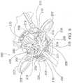
- FIGS 9-12show an articulation mechanism 200 in accordance with the invention.
- Articulation mechanism 200controls bending or turning motion at wrist section 170, which permits the upper jaw 120 and lower jaw 132 to bend left or right. More specifically, articulation mechanism 200 is operable to apply a tension force to one of the articulation wire sections 172 and 174 to bend the device at wrist section 170.
- Articulation mechanism 200includes a pair of indexing disks 210 that hold the articulated position of the upper and lower jaws 120 and 132. Articulator mechanism 200 also includes an articulator 220 operable to rotate the indexing disks 210. Articulator 220 has a pair of handles 222 that extend outwardly from the indexing disks. Handles 222 and indexing disks 210 are rotatably displaceable in a housing 230. Housing 230 has an interior wall 232 lined with ratchet notches 234. Each indexing disk 210 has a pair of indexing arms 212 operable to engage and disengage ratchet notches 234 when the indexing disk is rotated in housing 230.
- Ratchet notches 234are separated from one another by a series of inwardly pointing ratchet teeth 235.
- Each indexing arm 212has a distal end 213 with a pointed tip 215 configured to slidably interact and engage with ratchet notches 234 and ratchet teeth 235 as indexing disks 210 rotate in the housing.
- Indexing arms 212are formed of resilient flexible material that allows the indexing arms to flex or bend radially inwardly toward the center of indexing disks 210 in response to contact between tip 215 and indexing teeth 235. When tips 215 engage the inner most sections of ratchet teeth 235, indexing arms 212 bend inwardly under stored energy. As indexing disks 210 rotate and the tips 215 align with ratchet notches 234, indexing arms 212 snap outwardly and return to a relaxed state with the tips positioned in the ratchet notches.
- Articulation mechanism 200includes a centering mechanism 240 that biases articulator 220 to a centered or "neutral" condition.
- the neutral conditionis shown in Figure 9 .
- Centering mechanism 240includes a pair of flexible leaf springs 216 that extend from each indexing disk 210.
- Each leaf spring 216has a distal end 217 that is held in a captive position between a pair of projections 226 on articulator 220.
- each leaf spring 216is substantially straight, in a relaxed state.
- projections 226also rotate, but the indexing disks 210 do not rotate immediately, and instead remain stationary, as will be explained in more detail below.
- each leaf spring 216bends in response to initial movement of the projections 226, storing energy in the leaf spring that creates a biasing force.
- the biasing force in each leaf spring 216applies force to articulator 220 in the direction opposite of the direction in which the articulator was rotated, to urge the articulator back toward the neutral condition.
- the biasing force in leaf springs 216returns articulator 200 back to the neutral condition.
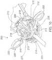
- Articulation mechanism 200further includes an automatic locking mechanism 250.
- Locking mechanism 250is a passive interlock mechanism that prevents external force on the upper and lower jaws 120 and 132 from moving the jaws out of their indexed position.
- Locking mechanism 250includes four detents 228 on articulator 220, two of which are visible in the Figures, and two which are on the opposite side of the articulator. Each detent 228 is movable with respect to indexing disks 210 between a locking position and a release position. In the locking position, shown in Figure 9 , each detent 228 is aligned with an inner projection 219 on one of the indexing arms 212.
- inner projections 219block the indexing arms and prevent them from bending inwardly, thereby preventing the indexing arms from disengaging the ratchet notches and precluding articulation of the jaws from their indexed position.
- each detent 228is rotated out of alignment with the corresponding inner projection 219, allowing the indexing arms to bend inwardly and disengage the ratchet notches to facilitate articulation of the jaws to another position.
- articulation mechanism 200is a floating mechanism that is biased toward the neutral condition with respect to the indexing disks.
- the jawsare articulated by rotating articulator 220 either clockwise or counterclockwise relative to housing 230 via the handles 222.
- rotation forceis initially applied to handles 222, the applied force is opposed by the centering forces of leaf springs 216. If the applied force is greater than the centering forces, articulator 220 will rotate relative to indexing disks 210 so that the detents 228 move out of the locking position to the release position.
- Articulator 220has four abutment edges 225, and indexing disks 210 have corresponding abutment edges 211.
- abutment edges 211are spaced apart from abutment edges 225, creating small gaps 229 that define limits of travel.
- articulator 220Upon initial rotation of handles 222, articulator 220 will rotate, and two of the abutment edges 225 will approach corresponding abutment edges 211 on indexing disks 210.
- handles 222are rotated through a small threshold angle of rotation, such as 5 degrees, the abutment edges 225 approaching the abutment edges 211 on indexing disks 210 will reach their limit of travel and contact the indexing disks 210.
- indexing disks 210rotate the indexing disks in tandem with articulator 220.
- the tips 215 of indexing arms 212bend inwardly as they slidably engage ratchet teeth 235 and snap outwardly as they align with ratchet notches 234 in the next indexed position.
- rotation forceis released from handles 222, so that leaf springs 216 return articulator 220 to the neutral condition, with detents 228 returned to the locking position.
- detents 228prevent indexing arms 212 from disengaging ratchet notches 234, effectively locking articulation wires 172 and 174 and wrist 170 in the indexed position.
- device 100includes a spring plate 260 which is attached to proximal ends of articulation wires 172 and 174.
- Spring plate 260places articulation wires 172 and 174 in tension to secure components in wrist 170 together, thereby avoiding the need to use other means to physically join the wrist components.
- Indexing disks 210hold spring plate 260 in place in housing 230.
- Each articulation wire 172 and 174extends through a hole in a wing portion 262 of spring plate 260.
- the proximal end of each articulation wire 172 and 174is bent and captured in a wire stopper 270.
- Each wire stopper 270is keyed to maintain its orientation against spring plate 260.
- Each wing portion 262has a relaxed state in which the wing portion is bent in a proximal direction with respect to the rest of the spring plate 260. In the assembled state, the wire stoppers 270 are pulled distally against wing portions 262 to tension the articulation mechanism 200.
- Embodimentsmay include a wrist mechanism with components having "non-circular" pivot interfaces.
- the pivot interfaces between componentsmay have parabolic, stepped or V-notched geometries, resulting in a moving axis of rotation rather than a traditional fixed axis of rotation associated with strictly "circular" geometries, such as spherical or cylindrical interfacing geometries.
- the moving axis of rotationprovides the benefit of a self-straightening or self-centering coupling in which the adjoined vertebrae are urged to return to a straight configuration after being articulated. This bias toward a straightened configuration stabilizes the position of the jaws and provides resistance against jogging when the jaws are locked or contacting other objects.
- the non-circular interfacealso combats the loss of compression force exhibited by the jaws when the jaws are articulated by lengthening the effective shaft length.
- lengthening the shaft(without changes in the jaw locking mechanism) will result in pulling harder for more compression force.
- Figure 13shows one example of a non-circular interface 171 between vertebra 173 and a bushing 182 in wrist section 170.
- Non-circular interface 171includes a rounded convex mating surface 175 on vertebra 173, and a rounded concave mating surface 184 on bushing 182.
- a step or "lobe" 177extends outwardly from convex mating surface 175. The surface transitions between lobe 177 and convex mating surface 175 are rounded, forming a smooth compound curvature along the edge of vertebra 173.
- a recess 185extends into concave mating surface 184 and has a shape that conforms to the geometry of lobe 177 as shown.
- convex mating surface 175 and lobe 177are in phase with concave mating surface 184 and recess 185, with the lobe nested in the recess.
- convex mating surface 175 and lobe 177are shifted out of phase with concave mating surface 184 and recess 185, such that the lobe moves out of the recess and engages the concave mating surface.
- the distance between vertebra 173 and bushing 182is incrementally increased, shifting the axis of rotation between the parts.
- the dimension of lobe 177may be very small relative to the size of convex mating surface 175.
- the rounded perimeter of lobe 177may project as little as 0,0508 mm (0.002 inches) from convex mating surface 175. Smaller or larger lobe configurations may also be used.
Landscapes
- Health & Medical Sciences (AREA)
- Surgery (AREA)
- Engineering & Computer Science (AREA)
- Life Sciences & Earth Sciences (AREA)
- Biomedical Technology (AREA)
- Otolaryngology (AREA)
- Nuclear Medicine, Radiotherapy & Molecular Imaging (AREA)
- Plasma & Fusion (AREA)
- Physics & Mathematics (AREA)
- Heart & Thoracic Surgery (AREA)
- Medical Informatics (AREA)
- Molecular Biology (AREA)
- Animal Behavior & Ethology (AREA)
- General Health & Medical Sciences (AREA)
- Public Health (AREA)
- Veterinary Medicine (AREA)
- Surgical Instruments (AREA)
Description
- The present application generally relates to electrosurgical instruments having opposing jaws for cutting and sealing tissue, and more specifically to electrosurgical instruments with jaws having improved stiffness and compressive strength, and an improved articulation mechanism.
- Biopolar electrosurgical instruments apply radiofrequency (RF) energy to a surgical site to cut, ablate, or coagulate tissue. A particular application of these electrosurgical effects is to seal blood vessels or tissue sheets. A typical instrument takes the form of a pair of opposing jaws or forceps, with one or more electrodes on each jaw tip. In an electrosurgical procedure, the electrodes are placed in close proximity to each other as the jaws are closed on a target site such that the path of alternating current between the two electrodes passes through tissue within the target site. The mechanical force exerted by the jaws and the electrical current combine to create the desired surgical effect. By controlling the level of mechanical and electrical parameters, such as the pressure applied by the jaws, the gap distance between electrodes, and the voltage, current, frequency, and duration of the electrosurgical energy applied to the tissue, the surgeon can coagulate, cauterize, or seal tissue toward a therapeutic end.
US 2011/230875 A1 discloses e.g. an electrosurgical device for cutting and sealing tissue, comprising an upper jaw located at a distal end of the electrosurgical device and opposing a lower jaw, the lower jaw being pivotally connected to the upper jaw by a pivot connection, and an articulation mechanism for controlling bending or turning motion of the upper and lower jaws, wherein the articulation mechanism comprises a housing and an indexing disk arranged rotatably displaceable in the housing, wherein the housing comprises a plurality of ratchet notches and the indexing disk comprises an indexing arm for engaging the ratchet notches to index the position of the upper and lower jaws.WO 2010/104755 A1 discloses an endoscopic vessel sealer and divider having a flexible articulating shaft.- Electrosurgical procedures can be performed in an open environment, through conventional incisions, or using laparoscopic procedures. In laparoscopic procedures, the electrosurgical instrument must be able to fit through a cannula or trocar having a very small inner diameter that is typically between 5 mm and 10 mm. It is possible to make an electrosurgical instrument small enough to meet this size requirement. Nevertheless, the push to make instruments smaller often competes against other equally important design criteria.
- The compression force exerted by the instrument is one of the most important design criteria that competes with instrument size. Ordinarily, a high compression force between the jaws is needed to form a proper seal within a reasonably short amount of time. Without sufficient compression force, the instrument may not be able to form a proper seal, or may form a proper seal only after a long time. It can be very difficult to create sufficient compression force with a smaller electrosurgical instrument because as the size of the instrument decreases, the percentage of space taken up by non-structural elements in the jaws increases. For example, the components that control tissue cutting, jaw actuation, articulation and power delivery all take up space in the jaws. Each component requires the removal of material from the jaws to provide space for the component. This reduces material mass and stiffness in the jaws, thereby reducing the compression force that can be created.
- Based on the foregoing, there is a need for improved electrosurgical devices that can be reduced in size without sacrificing important parameters like compressive strength.
- According to one example of the invention, an electrosurgical device for cutting and sealing tissue includes an upper jaw located at a distal end of the electrosurgical device that opposes a lower jaw. The lower jaw is pivotally connected to the upper jaw by a pivot connection. The electrosurgical device further comprises an articulation mechanism for controlling bending or turning motion of the upper and lower jaws. The articulation mechanism comprises a housing and an indexing disk arranged rotatably displaceable in the housing. The housing comprises a plurality of ratchet notches and the indexing disk comprises an indexing arm for engaging the ratchet notches to index the position of the upper and lower jaws. The articulation mechanism further comprises an automatic locking mechanism. The automatic locking mechanism is a passive interlock mechanism preventing external force on the upper and lower jaws from moving the upper and lower jaws out of an indexed position.
- The foregoing summary and the following detailed description will be better understood in conjunction with the drawing figures, of which:
FIG. 1 is a truncated perspective view of an electrosurgical device in accordance with one embodiment;FIG. 2 is a truncated perspective view of electrosurgical device components that can be used in the embodiment ofFigure 1 or other embodiments;FIG. 3 is another truncated perspective view of electrosurgical device components that can be used in the embodiment ofFigure 1 or other embodiments;FIG. 4 is another truncated perspective view of electrosurgical device components that can be used in the embodiment ofFigure 1 or other embodiments;FIG. 5 is another truncated perspective view of electrosurgical device components that can be used in the embodiment ofFigure 1 or other embodiments;FIG. 6 is another truncated perspective view of electrosurgical device components that can be used in the embodiment ofFigure 1 or other embodiments;FIG. 7 is a schematic diagram illustrating arcs that correspond to arc lengths of actuation wires in a cross configuration that may be used in the embodiment ofFigure 1 or other embodiments;FIG. 8 is another truncated perspective view of electrosurgical device components that can be used in the embodiment ofFigure 1 or other embodiments;FIG. 9 is another truncated perspective view of electrosurgical device components that can be used in the embodiment ofFigure 1 or other embodiment, showing components of an articulation mechanism, with some components removed for clarity;FIG. 10 is another truncated perspective view of the components ofFIG. 9 , with some components removed for clarity;FIG. 11 is another truncated perspective view of the components ofFIG. 9 , with some components removed for clarity;FIG. 12 is another truncated perspective view of the components ofFIG. 9 , with some components removed for clarity;FIG. 13 is a plan view of a pivot interface between components that can be used in the embodiment ofFigure 1 or other embodiments;FIG. 14 is a truncated perspective view of an electrosurgical device with components removed to show the configuration of internal components that can be used in the embodiment ofFigure 1 or other embodiments;FIG. 15 is an enlarged truncated partial cross section view of an electrosurgical device showing the configuration of internal components that can be used in the embodiment ofFigure 1 or other embodiments;FIG. 16 is another enlarged truncated partial cross section view of an electrosurgical device showing the configuration of internal components that can be used in the embodiment ofFigure 1 or other embodiments; andFIG. 17 is a truncated perspective view of an electrosurgical device showing the configuration of internal components that can be used in the embodiment ofFigure 1 or other embodiments.- Applicants have developed improved electrosurgical devices that address the need for reduced size, while also addressing the need for high compression force between the jaws. The improved electrosurgical devices were designed using a holistic approach that eliminates, simplifies, or combines individual components where appropriate, while maximizing strength and stiffness in the jaws.
- The following examples illustrate features that are designed to address the competing needs for reduced size and for stronger stiffer jaws. Although different features will be described and shown on an
electrosurgical device 100, many of the features are independent features. Some or all of these features can appear on the same device, but need not be on the same device, and can be used in different combinations on different embodiments of the invention. Devices in accordance with the invention may include many of the device features and characteristics shown and described inU.S. Publication No. 2009-019272 A1 andPat. No. 8,870,867 . - Referring to
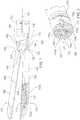
Figure 1 , anelectrosurgical device 100 is shown in accordance with one exemplary embodiment.Device 100 includes anelongated shaft 102. Elongatedshaft 102 has adistal end portion 110 that features anupper jaw 120 and alower jaw housing 130.Lower jaw housing 130 contains alower jaw 132. Acutting blade 160, shown inFigures 2 and3 , is displaceable between the upper andlower jaws Upper jaw 120 andlower jaw housing 130 are pivotally joined by apivot connection 140 that allows the upper jaw to pivot relative to the lower jaw housing to open and close the upper jaw.Pivot connection 140 includes asemi-cylindrical element 142 having aconvex surface 143 that engages afirst side 122 ofupper jaw 120.Pivot connection 140 also includes an arc-shapedconcave surface 144 that engages asecond side 124 ofupper jaw 120.Convex surface 143 andconcave surface 144 follow circular profiles that are concentric about apivot point 148.Semi-cylindrical element 142 andconcave surface 144 are separated from one another by anarcuate passage 145. The edges ofarcuate passage 145 form a track orchute 146 through which theupper jaw 120 slides. The arcuate shape oftrack 146 causes theupper jaw 120 to pivot relative tolower jaw housing 130 as the upper jaw slides through the passage.Upper jaw 120 pivots aboutpivot point 148.- As can be seen in
Figures 1 and3 ,pivot connection 140 differs from conventional pin connections in significant ways. As an initial matter,pivot connection 140 does not require the removal of material from the jaws.Upper jaw 120 fits into the body oflower jaw housing 130 througharcuate passage 145, with little or no void space in or around the upper jaw and lower jaw housing. Conventional pin connections, in contrast, require the removal of material to accommodate the pin and to allow each jaw to pivot relative to one another. Removal of material from the jaws reduces the mass of the jaws, and consequently, the amount of stiffness and compression force that can be exerted on tissue when the jaws are closed. Pivot connection 140 also differs from conventional pin connections with regard to the position of the pivot connection relative to the jaws. Pin connections are typically located along the midline of the instrument between the upper and lower jaws.Pivot point 148, in contrast, is offset from acenter line 101 of the device, adjacent to theoutside edge 121 ofupper jaw 120. This offset arrangement has an advantage over cross pin connections located on the midline because it provides a clear unobstructed path through the midline. The unobstructed path allows cuttingblade 160 to travel along the midline between the blades, without any obstruction created by a pin.- The electrode configuration in
device 100 is another feature that balances the need for reduced size and increased jaw stiffness. Many known electrosurgical devices use one or more stand-alone electrodes placed on the jaws. Stand-alone electrodes require space to capture, isolate and house the electrodes in the jaws, sacrificing stiffness in the jaws. To address this problem,device 100 is designed without stand-alone electrodes. Power is delivered directly toupper jaw 120 andlower jaw housing 130. - Known electrosurgical devices deliver power to electrodes using dedicated power transmission wires that extend through the jaws. In many cases, these dedicated power transmission wires are in the form of stationary braided or jacketed wires. Dedicated power transmission wires occupy a significant amount of space and require throughbores, passages, etc. that remove material from the jaws. As such, dedicated power transmission wires and their throughbores decrease jaw stiffness, thereby reducing the amount of compressive force that can be applied between the jaws during sealing. Dedicated power transmission wires can also limit movement of the instrument in cases where the dedicated wires do not have sufficient slack or elasticity to move or stretch as the instrument moves.
- To preserve stiffness in the jaws and provide greater instrument mobility and flexibility, devices in accordance with the invention preferably include multifunctional components that control both motion and power delivery. Dedicated power transmission wires that sacrifice jaw stiffness and instrument mobility are preferably avoided. Energy delivery can be provided through the same components that control actuation and/or articulation, for example. Energy delivery can also be provided through translating components.
- Referring to
Figure 2 , a cross section ofdevice 100 is shown at the "wrist" or "vertebra"section 170.Wrist section 170, which is described in more detail in a later section, includes avertebra 173 that is substantially solid, with the exception of four through-passages. Two through passages accommodate a loopedarticulation wire 167, and one through passage accommodates a loopedactuation wire 169.Articulation wire 167 is operable to allow distal end portion of the device to bend relative to the longitudinal axis of the device.Actuation wire 169 is operable to open and closeupper jaw 120.Articulation wire 167 is looped through the passages, forming two generally parallelarticulation wire sections actuation wire 169 is looped through the passages, forming two generally parallelactuation wire sections Actuation wire sections Figure 2 , as will be explained in more detail.Figures 3 and14 show howarticulation wire 167 andactuation wire 169 are routed through a distal end portion of the device, with a looped end of the articulation wire visible. - A first through-
passage 173a located in an outer peripheral section ofvertebra 173 contains the firstarticulation wire section 172. A second through-passage 173b located in another outer peripheral section ofvertebra 173 contains the secondarticulation wire section 174. A third through-passage 173c located in an interior section ofvertebra 173 contains cuttingblade 160. A fourth through-passage 173d located in an interior section ofvertebra 173 containsactuation wire sections - Power is delivered to
upper jaw 120 throughactuation wire 169. Power is delivered to thelower jaw housing 130 througharticulation wire 167, and may also be delivered through any other series of metal components, including jaw bushings, vertebra or shafts that may be metal and that contact each other in series, and which are isolated fromactuation wire 169.Lower jaw housing 130 andlower jaw 132 both include metal surfaces in contact with one another, so that power delivered to the lower jaw housing is conducted to the lower jaw. - Surfaces on
upper jaw 120 that interface withlower jaw housing 130 andlower jaw 132 must be electrically isolated. To address this,device 100 includes aplastic skin 180 overupper jaw 120.Upper jaw 120 is over-molded with theplastic skin 180 to isolate the surfaces that interface withlower jaw housing 130. The over-mold does not require clearance between components, preserving space to allow the jaws to have more material mass. Over-moldingupper jaw 120 also allows offsetting features to be created on the upper jaw, as will be explained in the next section. - The
over-molded skin 180 has multiple functions. A first function of the over-molded skin is to electrically isolateupper jaw 120 fromlower jaw housing 130, as described above. A second function of the over-molded skin is to generate offsetting features that create a gap space between the electrodes, i.e.upper jaw 120 andlower jaw 132, when the jaws are closed. InFigure 4 , an embodiment of the device includes offsetting features shown in the form ofstraps 150 that extend transversely acrossupper jaw 120.Straps 150 are produced during the over-mold process. A third function of the over-molded skin is to reduce the temperature of the back side of the jaw that comes into contact with the tissue, so as to reduce the risk of tissue burning. - Gap generating offset features in accordance with the invention need not take the form of transverse straps, and can be any surface irregularity or projection that provides a separation between electrodes when the jaws are closed. For example,
upper jaw 120 may include a plurality of holes that receive rivets or rivet-like members that project from the surface of the upper jaw and contactlower jaw 132. - The
lower jaw 132 is pivotally connected tolower jaw housing 130 by a lowerjaw pivot connection 190.Pivot connection 190 betweenlower jaw 132 andlower jaw housing 130 represents one of the most critical areas where stiffness and strength must be maximized in the lower jaw to provide sufficient compression force. Pin connections and throughbores require removal of material from the lower jaw, reducing jaw stiffness and strength, as described above. Therefore,pivot connection 190 features a "pin-less" connection in the form of a pair ofbosses 136.Bosses 136 project outwardly fromlower jaw 132 and snap intosmall apertures 138 inlower jaw housing 130. With this arrangement, no material is removed fromlower jaw 132 across the width of the jaw at the location ofpivot connection 190. - As an alternative to bosses and apertures,
lower jaw housing 130 can be lightly crimped to create a pivoting interface between the lower jaw housing andlower jaw 132. - Referring to
Figure 5 ,jaw 132 has a rounded convexbottom surface 133, andlower jaw housing 130 has a rounded concave insidesurface 131. Concave insidesurface 131 bears against convexbottom surface 133 whenlower jaw housing 130 is pivoted relative toupper jaw 120. As such, concave insidesurface 131 and convexbottom surface 133 form bearing surfaces that absorb compression force betweenlower jaw 132 andlower jaw housing 130 and direct the compression force away from thebosses 136 andapertures 138. Consequently, the structural integrity oflower jaw 132 does not depend greatly on the strength ofbosses 136 orpivot connection 190. - One of the challenges of an articulating device is transmitting motion through the articulating members. When the device bends, the arc length through the joint changes as you move away from centerline. This generally requires the use of tall (for strength) and thin (for flexibility) actuation members which move along the centerline of the device. Articulation left and right prevents the use of short and flat actuation members or paired wire members arranged perpendicular to the articulation plane, because the members or wires will buckle and/or transmit motion and force unequally.
Device 100 uses anactuation wire 169 that is looped to form a pair ofparallel wire sections Actuation wire sections upper jaw 120 relative tolower jaw housing 130 when force is applied through the actuation wire sections. Loopedactuation wire 169 is connected to a pin (not shown) inupper jaw 120. To pivotupper jaw 120 to an open position, a pushing force (or force directed toward distal end portion 110) is applied to the upper jaw throughactuation wire sections upper jaw 120 to a closed position, a pulling force (or tension force directed away from the distal end portion 110) is applied to the upper jaw throughactuation wire sections actuation wire sections wires 180 degrees, crossing in the middle of the articulation members at a cross-over point P.Figure 2 is a cross section view ofdevice 100 taken through a plane that intersects the cross-over point P, whereactuation wire section 176 crosses overactuation wire section 178.Figure 14 is a perspective view of the distal end ofdevice 100, with components removed to show howwire section 176 crosses overwire section 178 at point P.Figure 15 is a cross section view ofdevice 100 that shows howactuation wire 169 connects withupper jaw 120.Actuation wire 169 is looped through aU-shaped slot 125 formed in a base portion ofupper jaw 120.Figures 16 and 17 are cross section views ofdevice 100 that show how actuationwires actuation wires Figure 7 . The crossover point P acts like a pivot point for the wires. By maintaining equal arc lengths, the forces are balanced between theactuation wire sections articulation wires Articulation wire sections - Referring to
Figure 8 ,upper jaw 120 has amating surface 131 that mates withlower jaw 132.Lower jaw 132 similarly has amating surface 133 that mates withupper jaw 120. Mating surfaces 131 and 133 each have a V-shaped contour as shown that provides several advantages over planar mating surfaces. - The V-shaped contour provides a self-alignment feature that keeps
upper jaw 120 andlower jaw 132 aligned with one another. The self-alignment feature eliminates the need for long component lengths and tight tolerance geometry behind the jaws to control alignment. The V-shaped mating surfaces 131 and 133 also have larger surface areas than planar surfaces, resulting an incrementally wider area to engage tissue. - The axial center line 123 of
mating surface 131 meets theaxial center line 135 ofmating surface 133 along aline 137 that is offset from acenter line 101 of thedevice 100. In this arrangement, the cutting plane 103 can be moved away fromcenter line 101 ofdevice 100, allowingcutting blade 160 to be located away from the center so that other components can be positioned toward the center of the device. - Referring back to
Figure 1 ,lower jaw housing 130 contains alower jaw spring 134 between the lower jaw housing andlower jaw 132.Lower jaw spring 134 bears against the inside oflower jaw housing 130 to pivotlower jaw 132. In this configuration,lower jaw spring 134 biases adistal portion 137 oflower jaw 132 towardsupper jaw 120. - Known electrosurgical devices that include lower jaw springs place the spring at a proximal section of the lower jaw, at a point located proximally with respect to the pivot point. To provide room for the spring, a certain amount of material is removed from the proximal portion of the lower jaw, and/or from the lower jaw housing in a similar area. This removal of material can create a substantial decrease in strength and stiffness at the proximal section of the lower jaw and/or lower jaw housing. Jaw strength and stiffness are especially important at the proximal section of the lower jaw and jaw housing because the proximal section is a critical area for providing compressive force.
Figure 1 shows the relative thickness of thelower jaw 132 at itsproximal section 135 and itsdistal section 137. - To avoid losing jaw strength and stiffness at the
proximal portion 135 oflower jaw 132,lower jaw spring 134 is located atdistal portion 137 of the lower jaw. This preserves more mass aroundproximal section 135 where it is needed.Distal section 137 oflower jaw 132 has more mass to begin with thanproximal section 135, and is therefore more suited for accommodatinglower jaw spring 134. Lower jaw spring 134 frictionally engageslower jaw 132 in two places, 132a and 132b. This engagement at two locations assists in transferring energy fromlower jaw housing 130 tolower jaw 132.Figures 9-12 show anarticulation mechanism 200 in accordance with the invention.Articulation mechanism 200 controls bending or turning motion atwrist section 170, which permits theupper jaw 120 andlower jaw 132 to bend left or right. More specifically,articulation mechanism 200 is operable to apply a tension force to one of thearticulation wire sections wrist section 170.Articulation mechanism 200 includes a pair ofindexing disks 210 that hold the articulated position of the upper andlower jaws Articulator mechanism 200 also includes anarticulator 220 operable to rotate theindexing disks 210.Articulator 220 has a pair ofhandles 222 that extend outwardly from the indexing disks.Handles 222 andindexing disks 210 are rotatably displaceable in ahousing 230.Housing 230 has aninterior wall 232 lined withratchet notches 234. Eachindexing disk 210 has a pair of indexingarms 212 operable to engage and disengageratchet notches 234 when the indexing disk is rotated inhousing 230.Ratchet notches 234 are separated from one another by a series of inwardly pointingratchet teeth 235. Eachindexing arm 212 has adistal end 213 with apointed tip 215 configured to slidably interact and engage withratchet notches 234 and ratchetteeth 235 asindexing disks 210 rotate in the housing. Indexingarms 212 are formed of resilient flexible material that allows the indexing arms to flex or bend radially inwardly toward the center ofindexing disks 210 in response to contact betweentip 215 andindexing teeth 235. Whentips 215 engage the inner most sections ofratchet teeth 235, indexingarms 212 bend inwardly under stored energy. Asindexing disks 210 rotate and thetips 215 align withratchet notches 234, indexingarms 212 snap outwardly and return to a relaxed state with the tips positioned in the ratchet notches.Articulation mechanism 200 includes a centeringmechanism 240 that biases articulator 220 to a centered or "neutral" condition. The neutral condition is shown inFigure 9 . Centeringmechanism 240 includes a pair offlexible leaf springs 216 that extend from eachindexing disk 210. Eachleaf spring 216 has adistal end 217 that is held in a captive position between a pair ofprojections 226 onarticulator 220. Whenarticulator 220 is in the neutral condition, eachleaf spring 216 is substantially straight, in a relaxed state. Whenarticulator 220 begins to rotate left or right,projections 226 also rotate, but theindexing disks 210 do not rotate immediately, and instead remain stationary, as will be explained in more detail below. As such, eachleaf spring 216 bends in response to initial movement of theprojections 226, storing energy in the leaf spring that creates a biasing force. The biasing force in eachleaf spring 216 applies force toarticulator 220 in the direction opposite of the direction in which the articulator was rotated, to urge the articulator back toward the neutral condition. When rotation force is released fromarticulator 200, the biasing force inleaf springs 216 returns articulator 200 back to the neutral condition.Articulation mechanism 200 further includes anautomatic locking mechanism 250.Locking mechanism 250 is a passive interlock mechanism that prevents external force on the upper andlower jaws Locking mechanism 250 includes fourdetents 228 onarticulator 220, two of which are visible in the Figures, and two which are on the opposite side of the articulator. Eachdetent 228 is movable with respect toindexing disks 210 between a locking position and a release position. In the locking position, shown inFigure 9 , eachdetent 228 is aligned with aninner projection 219 on one of the indexingarms 212. In this position,inner projections 219 block the indexing arms and prevent them from bending inwardly, thereby preventing the indexing arms from disengaging the ratchet notches and precluding articulation of the jaws from their indexed position. In the release position, shown inFigure 10 , eachdetent 228 is rotated out of alignment with the correspondinginner projection 219, allowing the indexing arms to bend inwardly and disengage the ratchet notches to facilitate articulation of the jaws to another position.- In this arrangement,
articulation mechanism 200 is a floating mechanism that is biased toward the neutral condition with respect to the indexing disks. In operation, the jaws are articulated by rotatingarticulator 220 either clockwise or counterclockwise relative tohousing 230 via thehandles 222. When rotation force is initially applied tohandles 222, the applied force is opposed by the centering forces of leaf springs 216. If the applied force is greater than the centering forces,articulator 220 will rotate relative toindexing disks 210 so that thedetents 228 move out of the locking position to the release position. Articulator 220 has fourabutment edges 225, andindexing disks 210 have corresponding abutment edges 211. When articulator is in the neutral condition, abutment edges 211 are spaced apart fromabutment edges 225, creatingsmall gaps 229 that define limits of travel. Upon initial rotation ofhandles 222,articulator 220 will rotate, and two of the abutment edges 225 will approach corresponding abutment edges 211 onindexing disks 210. Afterhandles 222 are rotated through a small threshold angle of rotation, such as 5 degrees, the abutment edges 225 approaching the abutment edges 211 onindexing disks 210 will reach their limit of travel and contact theindexing disks 210. At this point, rotational force applied to the handles will be transferred toindexing disks 210 and rotate the indexing disks in tandem witharticulator 220. Asindexing disks 210 rotate, thetips 215 of indexingarms 212 bend inwardly as they slidably engage ratchetteeth 235 and snap outwardly as they align withratchet notches 234 in the next indexed position. Upon reaching a desired indexed position, rotation force is released fromhandles 222, so thatleaf springs 216return articulator 220 to the neutral condition, withdetents 228 returned to the locking position. In the locking position,detents 228 prevent indexingarms 212 from disengagingratchet notches 234, effectively lockingarticulation wires wrist 170 in the indexed position.- Referring to
Figures 11 and 12 ,device 100 includes aspring plate 260 which is attached to proximal ends ofarticulation wires Spring plate 260 placesarticulation wires wrist 170 together, thereby avoiding the need to use other means to physically join the wrist components.Indexing disks 210hold spring plate 260 in place inhousing 230. Eacharticulation wire wing portion 262 ofspring plate 260. The proximal end of eacharticulation wire wire stopper 270. Eachwire stopper 270 is keyed to maintain its orientation againstspring plate 260. Eachwing portion 262 has a relaxed state in which the wing portion is bent in a proximal direction with respect to the rest of thespring plate 260. In the assembled state, thewire stoppers 270 are pulled distally againstwing portions 262 to tension thearticulation mechanism 200. - Embodiments may include a wrist mechanism with components having "non-circular" pivot interfaces. For example, the pivot interfaces between components may have parabolic, stepped or V-notched geometries, resulting in a moving axis of rotation rather than a traditional fixed axis of rotation associated with strictly "circular" geometries, such as spherical or cylindrical interfacing geometries. The moving axis of rotation provides the benefit of a self-straightening or self-centering coupling in which the adjoined vertebrae are urged to return to a straight configuration after being articulated. This bias toward a straightened configuration stabilizes the position of the jaws and provides resistance against jogging when the jaws are locked or contacting other objects.
- The non-circular interface also combats the loss of compression force exhibited by the jaws when the jaws are articulated by lengthening the effective shaft length. In devices which have a "pull" type mechanism to close the jaws, lengthening the shaft (without changes in the jaw locking mechanism) will result in pulling harder for more compression force.
Figure 13 shows one example of anon-circular interface 171 betweenvertebra 173 and abushing 182 inwrist section 170.Non-circular interface 171 includes a roundedconvex mating surface 175 onvertebra 173, and a roundedconcave mating surface 184 onbushing 182. A step or "lobe" 177 extends outwardly fromconvex mating surface 175. The surface transitions betweenlobe 177 andconvex mating surface 175 are rounded, forming a smooth compound curvature along the edge ofvertebra 173. A recess 185 extends intoconcave mating surface 184 and has a shape that conforms to the geometry oflobe 177 as shown.- When
wrist section 170 is straight (i.e. when the vertebrae are not articulated and the jaws are straight),convex mating surface 175 andlobe 177 are in phase withconcave mating surface 184 and recess 185, with the lobe nested in the recess. Whenwrist section 170 is articulated,convex mating surface 175 andlobe 177 are shifted out of phase withconcave mating surface 184 and recess 185, such that the lobe moves out of the recess and engages the concave mating surface. In this condition, the distance betweenvertebra 173 andbushing 182 is incrementally increased, shifting the axis of rotation between the parts. The dimension oflobe 177 may be very small relative to the size ofconvex mating surface 175. The rounded perimeter oflobe 177 may project as little as 0,0508 mm (0.002 inches) fromconvex mating surface 175. Smaller or larger lobe configurations may also be used. - While preferred embodiments of the invention have been shown and described herein, it will be understood that such embodiments are provided by way of example only. Numerous variations, changes and substitutions will occur to those skilled in the art without departing from the invention. Accordingly, it is intended that the appended claims cover all such variations as fall within the scope of the invention.
- 1. An electrosurgical device for cutting and sealing tissue, the electrosurgical device comprising:
- an upper jaw located at a distal end of the electrosurgical device and opposing a lower jaw, the lower jaw pivotally connected to the upper jaw by a pivot connection,
- wherein the pivot connection comprises a passage that contains a portion of the upper jaw, the upper jaw being axially displaceable through the passage to pivot the upper jaw relative to the lower jaw between a relatively open condition and a relatively closed condition, the upper jaw and lower jaw operable in the relatively closed condition to deliver RF energy to tissue.
- 2. The electrosurgical device of aspect 1, wherein the upper jaw is pivotable relative to the lower jaw about a pivot point located adjacent to an outside edge of the upper jaw, the pivot point being offset from a center line of the device.
- 3. The electrosurgical device of aspect 1, wherein the pivot connection comprises a semi-cylindrical element having a convex surface that engages a first side of the upper jaw.
- 4. The electrosurgical device of aspect 3, wherein the pivot connection further comprises a concave surface that engages a second side of the upper jaw.
- 5. The electrosurgical device of aspect 4, wherein the convex surface and the concave surface define opposing walls of the passage.
- 6. The electrosurgical device of aspect 4, wherein the convex surface and the concave surface follow circular profiles that are concentric about a common point.
- 7. The electrosurgical device of aspect 1 further comprising a lower jaw housing that contains the lower jaw, the lower jaw being positioned in a distal portion of the lower jaw housing.
- 8. The electrosurgical device of aspect 7, wherein the lower jaw is pivotally connected to the lower jaw housing by a lower jaw pivot connection.
- 9. The electrosurgical device of aspect 8, wherein the lower jaw pivot connection comprises a pin-less connection comprising a pair of bosses projecting outwardly from the lower jaw, the bosses engaging a pair of apertures in lower jaw housing.
- 10. The electrosurgical device of aspect 7 comprising a lower jaw spring positioned between the lower jaw housing and the lower jaw.
- 11. The electrosurgical device of aspect 10, wherein the lower jaw spring is located at a distal portion of the lower jaw, the lower jaw spring biasing a distal portion of the lower jaw towards the upper jaw.
- 12. The electrosurgical device of aspect 1, wherein the upper jaw comprises a plastic skin molded over the upper jaw to electrically isolate the upper jaw from the lower jaw.
- 13. The electrosurgical device of aspect 1 further comprising a wrist section between an elongated shaft of the electrosurgical device and the upper and lower jaws, the upper and lower jaws being displaceable at the wrist section to allow the upper and lower jaws to bend relative to the elongated shaft.
- 14. The electrosurgical device of aspect 13 further comprising an articulation wire looped through a passage in the wrist section.
- 15. The electrosurgical device of aspect 14, wherein power is delivered to the upper and lower jaws through the articulation wire.
- 16. The electrosurgical device of aspect 13, wherein the wrist section comprises a vertebra, a bushing and a self-straightening coupling between the vertebra and bushing to urge the upper and lower jaws toward a centered position.
- 17. The electrosurgical device of aspect 1, further comprising an actuation wire looped through a passage in one of the upper and lower jaws.
- 18. The electrosurgical device of aspect 17, wherein the actuation wire comprises a first actuation wire section and a second actuation wire section, the first actuation wire section crossing over the second actuation wire section so that the first and second actuation wire sections exert equal forces on said one of the upper and lower jaws through which the actuation wire is looped.
- 19. The electrosurgical device of aspect 17, wherein power is delivered to the upper and lower jaws through the actuation wire.
- 20. The electrosurgical device of aspect 1, wherein the upper jaw comprises a first mating surface and the lower jaw comprises a second mating surface that mates with the first mating surface, the first and second mating surfaces each comprising a V-shaped contour.
- 21. The electrosurgical device of aspect 1, further comprising an articulation mechanism for controlling bending or turning motion of the upper and lower jaws.
- 22. The electrosurgical device of aspect 21, wherein the articulation mechanism comprises a housing and an indexing disk rotatably displaceable in the housing.
- 23. The electrosurgical device of aspect 22, wherein the housing comprises a plurality of ratchet notches, and the indexing disc comprises an indexing arm for engaging the ratchet notches to index the position of the upper and lower jaws.
- 24. The electrosurgical device of aspect 22, wherein the articulation mechanism comprises an automatic locking mechanism that prevents external force on the upper and lower jaws from moving the upper and lower jaws out of an indexed position.
Claims (10)
- An electrosurgical device (100) for cutting and sealing tissue comprising an upper jaw (120) located at a distal end of the electrosurgical device (100) and opposing a lower jaw (132), the lower jaw (132) being pivotally connected to the upper jaw (120) by a pivot connection (140), and
an articulation mechanism (200) for controlling bending or turning motion of the upper and lower jaws (120,132), wherein
the articulation mechanism (200) comprises a housing (230) and an indexing disk (210) arranged rotatably displaceable in the housing (230), wherein the housing (230) comprises a plurality of ratchet notches (234) and the indexing disk (210) comprises an indexing arm (212) for engaging the ratchet notches (234) to index the position of the upper and lower jaws (120, 132),characterized in that
the articulation mechanism (200) further comprises an automatic locking mechanism (250), wherein the automatic locking mechanism (250) is a passive interlock mechanism preventing external force on the upper and lower jaws (120, 132) from moving the upper and lower jaws (120, 132) out of an indexed position. - The electrosurgical device (100) according to claim 1,characterized in that the articulation mechanism (200) comprises an articulator (220) being operable to rotate the indexing disk (210).
- The electrosurgical device (100) according to claim 2,characterized in that the articulation mechanism (200) includes a pair of indexing disks (210) that hold the articulated position of the upper and lower jaws (120, 132), and wherein each indexing disk (210) has a pair of indexing arms (212).
- The electrosurgical device (100) according to claim 3,characterized in that the ratchet notches (234) are separated from one another by a plurality of inwardly pointing ratchet teeth (235) and that the indexing arms (212) are operable to engage and disengage the ratchet notches (234) when the indexing disks (210) are rotated in the housing (230).
- The electrosurgical device (100) according to claim 3 or 4,characterized in that the articulation mechanism (200) comprises a centering mechanism (240) which comprises a pair of leaf springs (216) extending from each indexing disk (210) and having a distal end that is held in a captive position between a pair of projections (226) provided on the articulator (200), the centering mechanism (240) exerting a centering force and biasing the articulator (220) to a centered condition.
- The electrosurgical device (100) according to any one of claims 3 to 5,characterized in that the automatic locking mechanism (250) includes four detents (228) on the articulator (220), wherein each detent (228) is movable with respect to the indexing disks (210) between a locking position and a release position.
- The electrosurgical device (100) according to claim 5 or 6,characterized in that the articulator (220) has a pair of handles (222) extending outwardly from the indexing disks (210)and the upper and lower jaws (120, 132) are articulated by exerting a rotation force on the handles (222), wherein the rotation force is opposed by the centering force.
- The electrosurgical device (100) according to claim 7,characterized in that the articulator (220) rotates relatively to the indexing disk (210) and thus the detents (228) move out of the locking position to the release position in the case of the rotation force being greater than the centering force.
- The electrosurgical device (100) according to claim 7 or 8,characterized in that the articulator (220) has four abutment edges (225) and the indexing disks (210) have corresponding abutment edges (211), wherein the abutment edges (225) of the articulator (220) and the abutment edges (211) of the indexing disks (210) approach and contact each other when the rotation force is applied to the handles (222) of the articulator (220), wherein the indexing disks (210) and the articulator (220) rotate in tandem with each other when the abutment edges (225) of the articulator (220) are in contact with the abutment edges (211) of the indexing disks (210).
- The electrosurgical device (100) according to any one of the preceding claims,characterized in that the pivot connection (140) comprises a passage (145) that contains a portion of the upper jaw (120), the upper jaw (120) being axially displaceable through the passage (145) to pivot the upper jaw (120) relative to the lower jaw (132) between a relatively open condition and a relatively closed condition, the upper jaw (120) and lower jaw (132) being operable in the relatively closed condition to deliver RF energy to tissue.
Applications Claiming Priority (2)
| Application Number | Priority Date | Filing Date | Title |
|---|---|---|---|
| US201261705721P | 2012-09-26 | 2012-09-26 | |
| EP13798723.6AEP2900162B1 (en) | 2012-09-26 | 2013-09-26 | Apparatus for tissue cutting and sealing |
Related Parent Applications (2)
| Application Number | Title | Priority Date | Filing Date |
|---|---|---|---|
| EP13798723.6ADivisionEP2900162B1 (en) | 2012-09-26 | 2013-09-26 | Apparatus for tissue cutting and sealing |
| EP13798723.6ADivision-IntoEP2900162B1 (en) | 2012-09-26 | 2013-09-26 | Apparatus for tissue cutting and sealing |
Publications (2)
| Publication Number | Publication Date |
|---|---|
| EP2997922A1 EP2997922A1 (en) | 2016-03-23 |
| EP2997922B1true EP2997922B1 (en) | 2017-12-20 |
Family
ID=49681068
Family Applications (4)
| Application Number | Title | Priority Date | Filing Date |
|---|---|---|---|
| EP15183441.3AActiveEP2997921B1 (en) | 2012-09-26 | 2013-09-26 | Apparatus for tissue cutting and sealing |
| EP15183442.1AActiveEP2997922B1 (en) | 2012-09-26 | 2013-09-26 | Apparatus for tissue cutting and sealing |
| EP15183443.9AActiveEP2997923B1 (en) | 2012-09-26 | 2013-09-26 | Apparatus for tissue cutting and sealing |
| EP13798723.6AActiveEP2900162B1 (en) | 2012-09-26 | 2013-09-26 | Apparatus for tissue cutting and sealing |
Family Applications Before (1)
| Application Number | Title | Priority Date | Filing Date |
|---|---|---|---|
| EP15183441.3AActiveEP2997921B1 (en) | 2012-09-26 | 2013-09-26 | Apparatus for tissue cutting and sealing |
Family Applications After (2)
| Application Number | Title | Priority Date | Filing Date |
|---|---|---|---|
| EP15183443.9AActiveEP2997923B1 (en) | 2012-09-26 | 2013-09-26 | Apparatus for tissue cutting and sealing |
| EP13798723.6AActiveEP2900162B1 (en) | 2012-09-26 | 2013-09-26 | Apparatus for tissue cutting and sealing |
Country Status (8)
| Country | Link |
|---|---|
| US (1) | US9872724B2 (en) |
| EP (4) | EP2997921B1 (en) |
| JP (4) | JP6336451B2 (en) |
| KR (3) | KR102174907B1 (en) |
| CN (3) | CN107252347B (en) |
| BR (3) | BR112015006554B1 (en) |
| ES (4) | ES2628297T3 (en) |
| WO (1) | WO2014049423A1 (en) |
Families Citing this family (17)
| Publication number | Priority date | Publication date | Assignee | Title |
|---|---|---|---|---|
| JP6336451B2 (en)* | 2012-09-26 | 2018-06-06 | アエスキュラップ アーゲー | Tissue cutting and sealing device |
| CN107920853A (en)* | 2015-08-05 | 2018-04-17 | 奥林巴斯株式会社 | Treatment apparatus |
| US11076908B2 (en) | 2016-06-02 | 2021-08-03 | Gyrus Acmi, Inc. | Two-stage electrosurgical device for vessel sealing |
| US10149726B2 (en)* | 2016-07-01 | 2018-12-11 | Ethicon Endo-Surgery, Llc | Methods, systems, and devices for initializing a surgical tool |
| EP3587054A4 (en)* | 2017-02-27 | 2020-11-11 | Asahi Intecc Co., Ltd. | Manipulator |
| US10932845B2 (en) | 2017-04-27 | 2021-03-02 | Ethicon Llc | Detent feature for articulation control in surgical instrument |
| GB2565575A (en)* | 2017-08-17 | 2019-02-20 | Creo Medical Ltd | Electrosurgical apparatus for delivering RF and/or microwave energy into biological tissue |
| WO2019089305A1 (en)* | 2017-10-30 | 2019-05-09 | Ethicon Llc | Surgical suturing instrument configured to manipulate tissue using mechanical and electrical power |
| CN108186081B (en)* | 2017-12-18 | 2019-12-17 | 南京天朗制药有限公司 | Surgical forceps with shearing function for hospital operating room |
| USD904611S1 (en) | 2018-10-10 | 2020-12-08 | Bolder Surgical, Llc | Jaw design for a surgical instrument |
| USD966513S1 (en)* | 2019-01-25 | 2022-10-11 | Karl Storz Se & Co. Kg | Shaft attachable medical instrument |
| JP1650796S (en)* | 2019-01-25 | 2020-01-20 | ||
| USD938588S1 (en)* | 2019-01-25 | 2021-12-14 | Karl Storz Se & Co. Kg | Shaft attachable medical instrument |
| JP1650869S (en)* | 2019-01-25 | 2020-01-20 | ||
| US11813017B2 (en) | 2019-03-11 | 2023-11-14 | Microline Surgical, Inc. | Reusable minimally invasive surgical instrument |
| IL265963A (en)* | 2019-04-10 | 2020-10-28 | Tamar Robotics Ltd | Needle with steering mechanism and tip navigation |
| CN114224475B (en)* | 2021-11-26 | 2024-10-11 | 艺柏湾医疗科技(上海)有限公司 | Surgical clamp, surgical clamp head and control method of clamp head |
Citations (1)
| Publication number | Priority date | Publication date | Assignee | Title |
|---|---|---|---|---|
| WO2010104755A1 (en)* | 2009-03-05 | 2010-09-16 | Tyco Healthcare Group Lp | Endoscopic vessel sealer and divider having a flexible articulating shaft |
Family Cites Families (535)
| Publication number | Priority date | Publication date | Assignee | Title |
|---|---|---|---|---|
| US2723108A (en) | 1951-02-24 | 1955-11-08 | Diamond Alkali Co | Valve |
| US3356408A (en) | 1966-07-07 | 1967-12-05 | Herbert D Sturtz | Camper anchoring device |
| US3527224A (en) | 1967-09-05 | 1970-09-08 | American Cyanamid Co | Method of surgically bonding tissue together |
| US3742955A (en) | 1970-09-29 | 1973-07-03 | Fmc Corp | Fibrous collagen derived product having hemostatic and wound binding properties |
| US3709215A (en) | 1970-12-28 | 1973-01-09 | S Richmond | Anterior vaginal retractor for vaginal surgery |
| US3845771A (en) | 1973-04-24 | 1974-11-05 | W Vise | Electrosurgical glove |
| DE2324658B2 (en) | 1973-05-16 | 1977-06-30 | Richard Wolf Gmbh, 7134 Knittlingen | PROBE FOR COAGULATING BODY TISSUE |
| JPS5239596B2 (en) | 1974-04-04 | 1977-10-06 | ||
| US3987795A (en) | 1974-08-28 | 1976-10-26 | Valleylab, Inc. | Electrosurgical devices having sesquipolar electrode structures incorporated therein |
| US4231372A (en) | 1974-11-04 | 1980-11-04 | Valleylab, Inc. | Safety monitoring circuit for electrosurgical unit |
| US4072153A (en) | 1976-03-03 | 1978-02-07 | Swartz William H | Post hysterectomy fluid drainage tube |
| US4041952A (en) | 1976-03-04 | 1977-08-16 | Valleylab, Inc. | Electrosurgical forceps |
| US4094320A (en) | 1976-09-09 | 1978-06-13 | Valleylab, Inc. | Electrosurgical safety circuit and method of using same |
| US5133727A (en)* | 1990-05-10 | 1992-07-28 | Symbiosis Corporation | Radial jaw biopsy forceps |
| WO1981003271A1 (en) | 1980-05-13 | 1981-11-26 | American Hospital Supply Corp | A multipolar electrosurgical device |
| US4492231A (en) | 1982-09-17 | 1985-01-08 | Auth David C | Non-sticking electrocautery system and forceps |
| US4590934A (en) | 1983-05-18 | 1986-05-27 | Jerry L. Malis | Bipolar cutter/coagulator |
| US4671274A (en) | 1984-01-30 | 1987-06-09 | Kharkovsky Nauchno-Issledovatelsky Institut Obschei I | Bipolar electrosurgical instrument |
| US5117118A (en) | 1988-10-19 | 1992-05-26 | Astex Co., Ltd. | Photoelectric switch using an integrated circuit with reduced interconnections |
| US4972846A (en) | 1989-01-31 | 1990-11-27 | W. L. Gore & Associates, Inc. | Patch electrodes for use with defibrillators |
| US5234425A (en) | 1989-03-03 | 1993-08-10 | Thomas J. Fogarty | Variable diameter sheath method and apparatus for use in body passages |
| US4979948A (en) | 1989-04-13 | 1990-12-25 | Purdue Research Foundation | Method and apparatus for thermally destroying a layer of an organ |
| US4976717A (en) | 1989-04-24 | 1990-12-11 | Boyle Gary C | Uterine retractor for an abdominal hysterectomy and method of its use |
| FR2647683B1 (en) | 1989-05-31 | 1993-02-12 | Kyocera Corp | BLOOD WATERPROOFING / COAGULATION DEVICE OUTSIDE BLOOD VESSELS |
| US5041101A (en) | 1989-06-05 | 1991-08-20 | Helix Medical, Inc. | Hysterectomy drain appliance |
| US4998527A (en) | 1989-07-27 | 1991-03-12 | Percutaneous Technologies Inc. | Endoscopic abdominal, urological, and gynecological tissue removing device |
| US5007908A (en) | 1989-09-29 | 1991-04-16 | Everest Medical Corporation | Electrosurgical instrument having needle cutting electrode and spot-coag electrode |
| US5665100A (en) | 1989-12-05 | 1997-09-09 | Yoon; Inbae | Multifunctional instrument with interchangeable operating units for performing endoscopic procedures |
| US6099550A (en) | 1989-12-05 | 2000-08-08 | Yoon; Inbae | Surgical instrument having jaws and an operating channel and method for use thereof |
| US5217030A (en) | 1989-12-05 | 1993-06-08 | Inbae Yoon | Multi-functional instruments and stretchable ligating and occluding devices |
| US5035696A (en) | 1990-02-02 | 1991-07-30 | Everest Medical Corporation | Electrosurgical instrument for conducting endoscopic retrograde sphincterotomy |
| EP0448857A1 (en) | 1990-03-27 | 1991-10-02 | Jong-Khing Huang | An apparatus of a spinning type of resectoscope for prostatectomy |
| US5108408A (en) | 1990-04-20 | 1992-04-28 | Lally James J | Uterine-ring hysterectomy clamp |
| US5078736A (en) | 1990-05-04 | 1992-01-07 | Interventional Thermodynamics, Inc. | Method and apparatus for maintaining patency in the body passages |
| US5482054A (en) | 1990-05-10 | 1996-01-09 | Symbiosis Corporation | Edoscopic biopsy forceps devices with selective bipolar cautery |
| US5037379A (en) | 1990-06-22 | 1991-08-06 | Vance Products Incorporated | Surgical tissue bag and method for percutaneously debulking tissue |
| US5282799A (en) | 1990-08-24 | 1994-02-01 | Everest Medical Corporation | Bipolar electrosurgical scalpel with paired loop electrodes |
| DE4032471C2 (en) | 1990-10-12 | 1997-02-06 | Delma Elektro Med App | Electrosurgical device |
| US5190541A (en) | 1990-10-17 | 1993-03-02 | Boston Scientific Corporation | Surgical instrument and method |
| US5085659A (en) | 1990-11-21 | 1992-02-04 | Everest Medical Corporation | Biopsy device with bipolar coagulation capability |
| US5178618A (en) | 1991-01-16 | 1993-01-12 | Brigham And Womens Hospital | Method and device for recanalization of a body passageway |
| US5370647A (en) | 1991-01-23 | 1994-12-06 | Surgical Innovations, Inc. | Tissue and organ extractor |
| US5219895A (en) | 1991-01-29 | 1993-06-15 | Autogenesis Technologies, Inc. | Collagen-based adhesives and sealants and methods of preparation and use thereof |
| US5749895A (en) | 1991-02-13 | 1998-05-12 | Fusion Medical Technologies, Inc. | Method for bonding or fusion of biological tissue and material |
| US5156613A (en) | 1991-02-13 | 1992-10-20 | Interface Biomedical Laboratories Corp. | Collagen welding rod material for use in tissue welding |
| AU660444B2 (en) | 1991-02-15 | 1995-06-29 | Ingemar H. Lundquist | Torquable catheter and method |
| US5300087A (en) | 1991-03-22 | 1994-04-05 | Knoepfler Dennis J | Multiple purpose forceps |
| US5396900A (en) | 1991-04-04 | 1995-03-14 | Symbiosis Corporation | Endoscopic end effectors constructed from a combination of conductive and non-conductive materials and useful for selective endoscopic cautery |
| DE4113037A1 (en) | 1991-04-22 | 1992-10-29 | Sutter Hermann Select Med Tech | BIPOLAR COAGULATION AND / OR CUTTING INSTRUMENT |
| US5484436A (en) | 1991-06-07 | 1996-01-16 | Hemostatic Surgery Corporation | Bi-polar electrosurgical instruments and methods of making |
| US5330471A (en) | 1991-06-07 | 1994-07-19 | Hemostatic Surgery Corporation | Bi-polar electrosurgical endoscopic instruments and methods of use |
| US5391166A (en) | 1991-06-07 | 1995-02-21 | Hemostatic Surgery Corporation | Bi-polar electrosurgical endoscopic instruments having a detachable working end |
| DE4130064A1 (en) | 1991-09-11 | 1993-03-18 | Wolf Gmbh Richard | ENDOSCOPIC COAGULATION GRIPPER |
| US5273524A (en) | 1991-10-09 | 1993-12-28 | Ethicon, Inc. | Electrosurgical device |
| US5312023A (en) | 1991-10-18 | 1994-05-17 | United States Surgical Corporation | Self contained gas powered surgical apparatus |
| US5711472A (en) | 1991-10-18 | 1998-01-27 | United States Surgical Corporation | Self contained gas powered surgical apparatus |
| US6250532B1 (en) | 1991-10-18 | 2001-06-26 | United States Surgical Corporation | Surgical stapling apparatus |
| US5326013A (en) | 1991-10-18 | 1994-07-05 | United States Surgical Corporation | Self contained gas powered surgical apparatus |
| US5478003A (en) | 1991-10-18 | 1995-12-26 | United States Surgical Corporation | Surgical apparatus |
| US5665085A (en) | 1991-11-01 | 1997-09-09 | Medical Scientific, Inc. | Electrosurgical cutting tool |
| US5207691A (en) | 1991-11-01 | 1993-05-04 | Medical Scientific, Inc. | Electrosurgical clip applicator |
| US5531744A (en) | 1991-11-01 | 1996-07-02 | Medical Scientific, Inc. | Alternative current pathways for bipolar surgical cutting tool |
| WO1993008754A1 (en) | 1991-11-01 | 1993-05-13 | Medical Scientific, Inc. | Electrosurgical cutting tool |
| US5713896A (en) | 1991-11-01 | 1998-02-03 | Medical Scientific, Inc. | Impedance feedback electrosurgical system |
| DE4138116A1 (en) | 1991-11-19 | 1993-06-03 | Delma Elektro Med App | MEDICAL HIGH-FREQUENCY COAGULATION CUTTER |
| US6024733A (en) | 1995-06-07 | 2000-02-15 | Arthrocare Corporation | System and method for epidermal tissue ablation |
| US5697882A (en) | 1992-01-07 | 1997-12-16 | Arthrocare Corporation | System and method for electrosurgical cutting and ablation |
| US6053172A (en) | 1995-06-07 | 2000-04-25 | Arthrocare Corporation | Systems and methods for electrosurgical sinus surgery |
| US6142992A (en) | 1993-05-10 | 2000-11-07 | Arthrocare Corporation | Power supply for limiting power in electrosurgery |
| US5681282A (en) | 1992-01-07 | 1997-10-28 | Arthrocare Corporation | Methods and apparatus for ablation of luminal tissues |
| US5484435A (en) | 1992-01-15 | 1996-01-16 | Conmed Corporation | Bipolar electrosurgical instrument for use in minimally invasive internal surgical procedures |
| US5352235A (en) | 1992-03-16 | 1994-10-04 | Tibor Koros | Laparoscopic grasper and cutter |
| US5158561A (en) | 1992-03-23 | 1992-10-27 | Everest Medical Corporation | Monopolar polypectomy snare with coagulation electrode |
| US5281216A (en) | 1992-03-31 | 1994-01-25 | Valleylab, Inc. | Electrosurgical bipolar treating apparatus |
| US5300068A (en) | 1992-04-21 | 1994-04-05 | St. Jude Medical, Inc. | Electrosurgical apparatus |
| US5443463A (en) | 1992-05-01 | 1995-08-22 | Vesta Medical, Inc. | Coagulating forceps |
| US5277201A (en) | 1992-05-01 | 1994-01-11 | Vesta Medical, Inc. | Endometrial ablation apparatus and method |
| US5443470A (en) | 1992-05-01 | 1995-08-22 | Vesta Medical, Inc. | Method and apparatus for endometrial ablation |
| US5562720A (en) | 1992-05-01 | 1996-10-08 | Vesta Medical, Inc. | Bipolar/monopolar endometrial ablation device and method |
| GR1002336B (en) | 1992-05-06 | 1996-05-21 | Ethicon Inc. | Endoscopic surgical apparatus capable of ligation and division. |
| US5293863A (en) | 1992-05-08 | 1994-03-15 | Loma Linda University Medical Center | Bladed endoscopic retractor |
| US6350274B1 (en) | 1992-05-11 | 2002-02-26 | Regen Biologics, Inc. | Soft tissue closure systems |
| NL9201118A (en) | 1992-06-24 | 1994-01-17 | Leuven K U Res & Dev | TOOL KIT FOR LAPAROSCOPIC VAGINAL HYSTERECTOMY. |
| US5221281A (en) | 1992-06-30 | 1993-06-22 | Valleylab Inc. | Electrosurgical tubular trocar |
| US5341807A (en) | 1992-06-30 | 1994-08-30 | American Cardiac Ablation Co., Inc. | Ablation catheter positioning system |
| US5250074A (en) | 1992-07-14 | 1993-10-05 | Wilk Peter J | Surgical instrument assembly and associated technique |
| US5720719A (en) | 1992-08-12 | 1998-02-24 | Vidamed, Inc. | Ablative catheter with conformable body |
| US5295990A (en) | 1992-09-11 | 1994-03-22 | Levin John M | Tissue sampling and removal device |
| US5374277A (en) | 1992-10-09 | 1994-12-20 | Ethicon, Inc. | Surgical instrument |
| US5431323A (en) | 1992-10-09 | 1995-07-11 | Ethicon, Inc. | Endoscopic surgical instrument with pivotable and rotatable staple cartridge |
| US5662662A (en) | 1992-10-09 | 1997-09-02 | Ethicon Endo-Surgery, Inc. | Surgical instrument and method |
| US5601224A (en) | 1992-10-09 | 1997-02-11 | Ethicon, Inc. | Surgical instrument |
| US5330502A (en) | 1992-10-09 | 1994-07-19 | Ethicon, Inc. | Rotational endoscopic mechanism with jointed drive mechanism |
| US5578052A (en) | 1992-10-27 | 1996-11-26 | Koros; Tibor | Insulated laparoscopic grasper with removable shaft |
| US5720745A (en) | 1992-11-24 | 1998-02-24 | Erbe Electromedizin Gmbh | Electrosurgical unit and method for achieving coagulation of biological tissue |
| US5558671A (en) | 1993-07-22 | 1996-09-24 | Yates; David C. | Impedance feedback monitor for electrosurgical instrument |
| US5403312A (en) | 1993-07-22 | 1995-04-04 | Ethicon, Inc. | Electrosurgical hemostatic device |
| US5462546A (en) | 1993-02-05 | 1995-10-31 | Everest Medical Corporation | Bipolar electrosurgical forceps |
| US5514134A (en) | 1993-02-05 | 1996-05-07 | Everest Medical Corporation | Bipolar electrosurgical scissors |
| US5336229A (en) | 1993-02-09 | 1994-08-09 | Laparomed Corporation | Dual ligating and dividing apparatus |
| US5342381A (en) | 1993-02-11 | 1994-08-30 | Everest Medical Corporation | Combination bipolar scissors and forceps instrument |
| US5431676A (en) | 1993-03-05 | 1995-07-11 | Innerdyne Medical, Inc. | Trocar system having expandable port |
| US5445638B1 (en) | 1993-03-08 | 1998-05-05 | Everest Medical Corp | Bipolar coagulation and cutting forceps |
| GB9306637D0 (en) | 1993-03-30 | 1993-05-26 | Smiths Industries Plc | Electrosurgery monitor and appartus |
| US5417687A (en) | 1993-04-30 | 1995-05-23 | Medical Scientific, Inc. | Bipolar electrosurgical trocar |
| GB9309142D0 (en) | 1993-05-04 | 1993-06-16 | Gyrus Medical Ltd | Laparoscopic instrument |
| US5395369A (en) | 1993-06-10 | 1995-03-07 | Symbiosis Corporation | Endoscopic bipolar electrocautery instruments |
| GB9314391D0 (en) | 1993-07-12 | 1993-08-25 | Gyrus Medical Ltd | A radio frequency oscillator and an electrosurgical generator incorporating such an oscillator |
| US5352223A (en) | 1993-07-13 | 1994-10-04 | Symbiosis Corporation | Endoscopic instruments having distally extending lever mechanisms |
| US5569243A (en) | 1993-07-13 | 1996-10-29 | Symbiosis Corporation | Double acting endoscopic scissors with bipolar cautery capability |
| GB9314641D0 (en) | 1993-07-15 | 1993-08-25 | Salim Aws S M | Tunnelling umbrella |
| US5356408A (en) | 1993-07-16 | 1994-10-18 | Everest Medical Corporation | Bipolar electrosurgical scissors having nonlinear blades |
| GR940100335A (en) | 1993-07-22 | 1996-05-22 | Ethicon Inc. | Electrosurgical device for placing staples. |
| US5709680A (en) | 1993-07-22 | 1998-01-20 | Ethicon Endo-Surgery, Inc. | Electrosurgical hemostatic device |
| US5810811A (en) | 1993-07-22 | 1998-09-22 | Ethicon Endo-Surgery, Inc. | Electrosurgical hemostatic device |
| US5693051A (en) | 1993-07-22 | 1997-12-02 | Ethicon Endo-Surgery, Inc. | Electrosurgical hemostatic device with adaptive electrodes |
| US5688270A (en) | 1993-07-22 | 1997-11-18 | Ethicon Endo-Surgery,Inc. | Electrosurgical hemostatic device with recessed and/or offset electrodes |
| US5336237A (en) | 1993-08-25 | 1994-08-09 | Devices For Vascular Intervention, Inc. | Removal of tissue from within a body cavity |
| US5718703A (en) | 1993-09-17 | 1998-02-17 | Origin Medsystems, Inc. | Method and apparatus for small needle electrocautery |
| US5405344A (en) | 1993-09-30 | 1995-04-11 | Ethicon, Inc. | Articulable socket joint assembly for an endoscopic instrument for surgical fastner track therefor |
| DE4333983A1 (en) | 1993-10-05 | 1995-04-06 | Delma Elektro Med App | High frequency electrosurgical instrument |
| US5496312A (en) | 1993-10-07 | 1996-03-05 | Valleylab Inc. | Impedance and temperature generator control |
| US5571100B1 (en) | 1993-11-01 | 1998-01-06 | Gyrus Medical Ltd | Electrosurgical apparatus |
| US5728143A (en) | 1995-08-15 | 1998-03-17 | Rita Medical Systems, Inc. | Multiple antenna ablation apparatus and method |
| US5449355A (en) | 1993-11-24 | 1995-09-12 | Valleylab Inc. | Retrograde tissue splitter and method |
| US5458598A (en) | 1993-12-02 | 1995-10-17 | Cabot Technology Corporation | Cutting and coagulating forceps |
| US5377415A (en) | 1993-12-10 | 1995-01-03 | Gibson; John | Sheet material punch |
| CA2138076A1 (en) | 1993-12-17 | 1995-06-18 | Philip E. Eggers | Monopolar electrosurgical instruments |
| US5603700A (en) | 1993-12-27 | 1997-02-18 | Daneshvar; Yousef | Suction and injection system |
| US5554159A (en) | 1994-02-04 | 1996-09-10 | Fischer; Nathan R. | Instrument for electro-surgical excisor for the transformation zone of the uterine cervix and method of using same |
| US5507773A (en) | 1994-02-18 | 1996-04-16 | Ethicon Endo-Surgery | Cable-actuated jaw assembly for surgical instruments |
| US5397320A (en) | 1994-03-03 | 1995-03-14 | Essig; Mitchell N. | Dissecting surgical device and associated method |
| US5445142A (en) | 1994-03-15 | 1995-08-29 | Ethicon Endo-Surgery, Inc. | Surgical trocars having optical tips defining one or more viewing ports |
| US5472442A (en) | 1994-03-23 | 1995-12-05 | Valleylab Inc. | Moveable switchable electrosurgical handpiece |
| US5766196A (en) | 1994-06-06 | 1998-06-16 | Tnco, Inc. | Surgical instrument with steerable distal end |
| US6056744A (en) | 1994-06-24 | 2000-05-02 | Conway Stuart Medical, Inc. | Sphincter treatment apparatus |
| US5540684A (en) | 1994-07-28 | 1996-07-30 | Hassler, Jr.; William L. | Method and apparatus for electrosurgically treating tissue |
| US5456684A (en) | 1994-09-08 | 1995-10-10 | Hutchinson Technology Incorporated | Multifunctional minimally invasive surgical instrument |
| US5573535A (en) | 1994-09-23 | 1996-11-12 | United States Surgical Corporation | Bipolar surgical instrument for coagulation and cutting |
| US6152920A (en) | 1997-10-10 | 2000-11-28 | Ep Technologies, Inc. | Surgical method and apparatus for positioning a diagnostic or therapeutic element within the body |
| US5520698A (en) | 1994-10-19 | 1996-05-28 | Blairden Precision Instruments, Inc. | Simplified total laparoscopic hysterectomy method employing colpotomy incisions |
| US5840077A (en) | 1994-10-18 | 1998-11-24 | Blairden Precision Instruments, Inc. | Uterine manipulating assembly for laparoscopic hysterectomy |
| US5833689A (en) | 1994-10-26 | 1998-11-10 | Snj Company, Inc. | Versatile electrosurgical instrument capable of multiple surgical functions |
| US5556397A (en) | 1994-10-26 | 1996-09-17 | Laser Centers Of America | Coaxial electrosurgical instrument |
| US5549637A (en) | 1994-11-10 | 1996-08-27 | Crainich; Lawrence | Articulated medical instrument |
| US5585007A (en) | 1994-12-07 | 1996-12-17 | Plasmaseal Corporation | Plasma concentrate and tissue sealant methods and apparatuses for making concentrated plasma and/or tissue sealant |
| US5558100A (en) | 1994-12-19 | 1996-09-24 | Ballard Medical Products | Biopsy forceps for obtaining tissue specimen and optionally for coagulation |
| US5632432A (en) | 1994-12-19 | 1997-05-27 | Ethicon Endo-Surgery, Inc. | Surgical instrument |
| US5704534A (en) | 1994-12-19 | 1998-01-06 | Ethicon Endo-Surgery, Inc. | Articulation assembly for surgical instruments |
| US5713505A (en) | 1996-05-13 | 1998-02-03 | Ethicon Endo-Surgery, Inc. | Articulation transmission mechanism for surgical instruments |
| GB9425781D0 (en) | 1994-12-21 | 1995-02-22 | Gyrus Medical Ltd | Electrosurgical instrument |
| US5611803A (en) | 1994-12-22 | 1997-03-18 | Urohealth Systems, Inc. | Tissue segmentation device |
| US5540685A (en) | 1995-01-06 | 1996-07-30 | Everest Medical Corporation | Bipolar electrical scissors with metal cutting edges and shearing surfaces |
| US5603711A (en) | 1995-01-20 | 1997-02-18 | Everest Medical Corp. | Endoscopic bipolar biopsy forceps |
| EP0957795B1 (en) | 1995-01-30 | 2005-10-19 | Boston Scientific Corporation | Electro-surgical tissue removal |
| US5637110A (en) | 1995-01-31 | 1997-06-10 | Stryker Corporation | Electrocautery surgical tool with relatively pivoted tissue engaging jaws |
| CA2168404C (en) | 1995-02-01 | 2007-07-10 | Dale Schulze | Surgical instrument with expandable cutting element |
| US5669907A (en) | 1995-02-10 | 1997-09-23 | Valleylab Inc. | Plasma enhanced bipolar electrosurgical system |
| US5715832A (en) | 1995-02-28 | 1998-02-10 | Boston Scientific Corporation | Deflectable biopsy catheter |
| US6391029B1 (en) | 1995-03-07 | 2002-05-21 | Enable Medical Corporation | Bipolar electrosurgical scissors |
| US5900245A (en) | 1996-03-22 | 1999-05-04 | Focal, Inc. | Compliant tissue sealants |
| US5868740A (en) | 1995-03-24 | 1999-02-09 | Board Of Regents-Univ Of Nebraska | Method for volumetric tissue ablation |
| US5599350A (en) | 1995-04-03 | 1997-02-04 | Ethicon Endo-Surgery, Inc. | Electrosurgical clamping device with coagulation feedback |
| JPH08279596A (en) | 1995-04-05 | 1996-10-22 | Mitsubishi Electric Corp | Integrated circuit device and manufacturing method thereof |
| US5624452A (en) | 1995-04-07 | 1997-04-29 | Ethicon Endo-Surgery, Inc. | Hemostatic surgical cutting or stapling instrument |
| US6203542B1 (en) | 1995-06-07 | 2001-03-20 | Arthrocare Corporation | Method for electrosurgical treatment of submucosal tissue |
| US5707369A (en) | 1995-04-24 | 1998-01-13 | Ethicon Endo-Surgery, Inc. | Temperature feedback monitor for hemostatic surgical instrument |
| US5697949A (en) | 1995-05-18 | 1997-12-16 | Symbiosis Corporation | Small diameter endoscopic instruments |
| US5637111A (en) | 1995-06-06 | 1997-06-10 | Conmed Corporation | Bipolar electrosurgical instrument with desiccation feature |
| US7090672B2 (en) | 1995-06-07 | 2006-08-15 | Arthrocare Corporation | Method for treating obstructive sleep disorder includes removing tissue from the base of tongue |
| US6837888B2 (en) | 1995-06-07 | 2005-01-04 | Arthrocare Corporation | Electrosurgical probe with movable return electrode and methods related thereto |
| US6363937B1 (en) | 1995-06-07 | 2002-04-02 | Arthrocare Corporation | System and methods for electrosurgical treatment of the digestive system |
| KR19990028365A (en) | 1995-06-23 | 1999-04-15 | 니겔 마크 고블 | Electrosurgical surgical instruments |
| GB9600377D0 (en) | 1996-01-09 | 1996-03-13 | Gyrus Medical Ltd | Electrosurgical instrument |
| EP1025807B1 (en) | 1995-06-23 | 2004-12-08 | Gyrus Medical Limited | An electrosurgical instrument |
| US6293942B1 (en) | 1995-06-23 | 2001-09-25 | Gyrus Medical Limited | Electrosurgical generator method |
| GB9526627D0 (en) | 1995-12-29 | 1996-02-28 | Gyrus Medical Ltd | An electrosurgical instrument and an electrosurgical electrode assembly |
| US6015406A (en) | 1996-01-09 | 2000-01-18 | Gyrus Medical Limited | Electrosurgical instrument |
| US6023638A (en) | 1995-07-28 | 2000-02-08 | Scimed Life Systems, Inc. | System and method for conducting electrophysiological testing using high-voltage energy pulses to stun tissue |
| US5653692A (en) | 1995-09-07 | 1997-08-05 | Innerdyne Medical, Inc. | Method and system for direct heating of fluid solution in a hollow body organ |
| US5667526A (en) | 1995-09-07 | 1997-09-16 | Levin; John M. | Tissue retaining clamp |
| US5683385A (en) | 1995-09-19 | 1997-11-04 | Symbiosis Corporation | Electrocautery connector for a bipolar push rod assembly |
| US5776130A (en) | 1995-09-19 | 1998-07-07 | Valleylab, Inc. | Vascular tissue sealing pressure control |
| US5674220A (en) | 1995-09-29 | 1997-10-07 | Ethicon Endo-Surgery, Inc. | Bipolar electrosurgical clamping device |
| US5817092A (en) | 1995-11-09 | 1998-10-06 | Radio Therapeutics Corporation | Apparatus, system and method for delivering radio frequency energy to a treatment site |
| US5979453A (en) | 1995-11-09 | 1999-11-09 | Femrx, Inc. | Needle myolysis system for uterine fibriods |
| EP0871405B1 (en) | 1995-11-20 | 2001-02-14 | Storz Endoskop GmbH | Bipolar high-frequency surgical instrument |
| US6461350B1 (en) | 1995-11-22 | 2002-10-08 | Arthrocare Corporation | Systems and methods for electrosurgical-assisted lipectomy |
| US6896672B1 (en) | 1995-11-22 | 2005-05-24 | Arthrocare Corporation | Methods for electrosurgical incisions on external skin surfaces |
| US5658281A (en) | 1995-12-04 | 1997-08-19 | Valleylab Inc | Bipolar electrosurgical scissors and method of manufacture |
| US5837001A (en) | 1995-12-08 | 1998-11-17 | C. R. Bard | Radio frequency energy delivery system for multipolar electrode catheters |
| US6245069B1 (en) | 1995-12-22 | 2001-06-12 | Karl Storz Gmbh & Co. Kg | Cutting loop electrode for high-frequency instrument |
| BR9612395A (en) | 1995-12-29 | 1999-07-13 | Gyrus Medical Ltd | Electrosurgical instrument and an electrosurgical electrode set |
| WO1997024074A1 (en) | 1995-12-29 | 1997-07-10 | Microgyn, Inc. | Apparatus and method for electrosurgery |
| GB9600354D0 (en) | 1996-01-09 | 1996-03-13 | Gyrus Medical Ltd | Electrosurgical instrument |
| US6090106A (en) | 1996-01-09 | 2000-07-18 | Gyrus Medical Limited | Electrosurgical instrument |
| US6013076A (en) | 1996-01-09 | 2000-01-11 | Gyrus Medical Limited | Electrosurgical instrument |
| US5683388A (en) | 1996-01-11 | 1997-11-04 | Symbiosis Corporation | Endoscopic bipolar multiple sample bioptome |
| US5755717A (en) | 1996-01-16 | 1998-05-26 | Ethicon Endo-Surgery, Inc. | Electrosurgical clamping device with improved coagulation feedback |
| DE19603981C2 (en) | 1996-02-05 | 1998-11-05 | Wolf Gmbh Richard | Medical instrument for uterine manipulation |
| US5702390A (en) | 1996-03-12 | 1997-12-30 | Ethicon Endo-Surgery, Inc. | Bioplar cutting and coagulation instrument |
| SE508742C2 (en) | 1996-03-25 | 1998-11-02 | Safe Conduct Ab | Device for use in endoscopic operations, to fix, enclose, divide and dispense a preparation |
| US5700261A (en) | 1996-03-29 | 1997-12-23 | Ethicon Endo-Surgery, Inc. | Bipolar Scissors |
| US5823066A (en) | 1996-05-13 | 1998-10-20 | Ethicon Endo-Surgery, Inc. | Articulation transmission mechanism for surgical instruments |
| US6066139A (en) | 1996-05-14 | 2000-05-23 | Sherwood Services Ag | Apparatus and method for sterilization and embolization |
| US5733283A (en) | 1996-06-05 | 1998-03-31 | Malis; Jerry L. | Flat loop bipolar electrode tips for electrosurgical instrument |
| DE19623840A1 (en) | 1996-06-14 | 1997-12-18 | Berchtold Gmbh & Co Geb | High frequency electrosurgical generator |
| GB2314274A (en) | 1996-06-20 | 1997-12-24 | Gyrus Medical Ltd | Electrode construction for an electrosurgical instrument |
| US6565561B1 (en) | 1996-06-20 | 2003-05-20 | Cyrus Medical Limited | Electrosurgical instrument |
| US5931836A (en) | 1996-07-29 | 1999-08-03 | Olympus Optical Co., Ltd. | Electrosurgery apparatus and medical apparatus combined with the same |
| US5735289A (en) | 1996-08-08 | 1998-04-07 | Pfeffer; Herbert G. | Method and apparatus for organic specimen retrieval |
| US6126682A (en) | 1996-08-13 | 2000-10-03 | Oratec Interventions, Inc. | Method for treating annular fissures in intervertebral discs |
| US5891134A (en) | 1996-09-24 | 1999-04-06 | Goble; Colin | System and method for applying thermal energy to tissue |
| US5954720A (en) | 1996-10-28 | 1999-09-21 | Endoscopic Concepts, Inc. | Bipolar electrosurgical end effectors |
| US6312430B1 (en) | 1996-10-28 | 2001-11-06 | Endoscopic Concepts, Inc. | Bipolar electrosurgical end effectors |
| US6371956B1 (en) | 1996-10-28 | 2002-04-16 | Endoscopic Concepts, Inc. | Monopolar electrosurgical end effectors |
| US7166102B2 (en) | 1996-10-30 | 2007-01-23 | Megadyne Medical Products, Inc. | Self-limiting electrosurgical return electrode |
| US6454764B1 (en) | 1996-10-30 | 2002-09-24 | Richard P. Fleenor | Self-limiting electrosurgical return electrode |
| US6544258B2 (en) | 1996-10-30 | 2003-04-08 | Mega-Dyne Medical Products, Inc. | Pressure sore pad having self-limiting electrosurgical return electrode properties and optional heating/cooling capabilities |
| US5735849A (en) | 1996-11-07 | 1998-04-07 | Everest Medical Corporation | Endoscopic forceps with thumb-slide lock release mechanism |
| NO303522B1 (en) | 1996-11-08 | 1998-07-27 | Nyfotek As | probe device |
| US5891142A (en) | 1996-12-06 | 1999-04-06 | Eggers & Associates, Inc. | Electrosurgical forceps |
| GB9626512D0 (en) | 1996-12-20 | 1997-02-05 | Gyrus Medical Ltd | An improved electrosurgical generator and system |
| US5893874A (en) | 1997-02-07 | 1999-04-13 | Smith & Nephew, Inc. | Surgical instrument |
| US7083613B2 (en) | 1997-03-05 | 2006-08-01 | The Trustees Of Columbia University In The City Of New York | Ringed forceps |
| US6626901B1 (en) | 1997-03-05 | 2003-09-30 | The Trustees Of Columbia University In The City Of New York | Electrothermal instrument for sealing and joining or cutting tissue |
| AU6948298A (en) | 1997-04-03 | 1998-10-22 | Cynthia D. Sadler | Hand-held forceps instrument |
| US6191365B1 (en) | 1997-05-02 | 2001-02-20 | General Science And Technology Corp | Medical devices incorporating at least one element made from a plurality of twisted and drawn wires |
| US6278057B1 (en) | 1997-05-02 | 2001-08-21 | General Science And Technology Corp. | Medical devices incorporating at least one element made from a plurality of twisted and drawn wires at least one of the wires being a nickel-titanium alloy wire |
| USH2037H1 (en) | 1997-05-14 | 2002-07-02 | David C. Yates | Electrosurgical hemostatic device including an anvil |
| USH1904H (en) | 1997-05-14 | 2000-10-03 | Ethicon Endo-Surgery, Inc. | Electrosurgical hemostatic method and device |
| US5817091A (en) | 1997-05-20 | 1998-10-06 | Medical Scientific, Inc. | Electrosurgical device having a visible indicator |
| US6296637B1 (en) | 1997-05-29 | 2001-10-02 | Link Technology, Inc. | Electrosurgical electrode and methods for its use |
| US5954715A (en) | 1997-06-05 | 1999-09-21 | Adiana, Inc. | Method and apparatus for tubal occlusion |
| US5899914A (en) | 1997-06-11 | 1999-05-04 | Endius Incorporated | Surgical instrument |
| GB2327352A (en) | 1997-07-18 | 1999-01-27 | Gyrus Medical Ltd | Electrosurgical instrument |
| US6096037A (en) | 1997-07-29 | 2000-08-01 | Medtronic, Inc. | Tissue sealing electrosurgery device and methods of sealing tissue |
| US6923803B2 (en) | 1999-01-15 | 2005-08-02 | Gyrus Medical Limited | Electrosurgical system and method |
| WO1999003408A1 (en) | 1997-07-18 | 1999-01-28 | Gyrus Medical Limited | An electrosurgical instrument |
| WO1999007297A1 (en) | 1997-08-05 | 1999-02-18 | Trustees Of Dartmouth College | System and methods for fallopian tube occlusion |
| US6102909A (en) | 1997-08-26 | 2000-08-15 | Ethicon, Inc. | Scissorlike electrosurgical cutting instrument |
| US6024744A (en) | 1997-08-27 | 2000-02-15 | Ethicon, Inc. | Combined bipolar scissor and grasper |
| WO1999012488A1 (en) | 1997-09-10 | 1999-03-18 | Sherwood Services Ag | Bipolar instrument for vessel fusion |
| US6258084B1 (en) | 1997-09-11 | 2001-07-10 | Vnus Medical Technologies, Inc. | Method for applying energy to biological tissue including the use of tumescent tissue compression |
| US6179832B1 (en) | 1997-09-11 | 2001-01-30 | Vnus Medical Technologies, Inc. | Expandable catheter having two sets of electrodes |
| US5836990A (en) | 1997-09-19 | 1998-11-17 | Medtronic, Inc. | Method and apparatus for determining electrode/tissue contact |
| US5865361A (en) | 1997-09-23 | 1999-02-02 | United States Surgical Corporation | Surgical stapling apparatus |
| US6494881B1 (en) | 1997-09-30 | 2002-12-17 | Scimed Life Systems, Inc. | Apparatus and method for electrode-surgical tissue removal having a selectively insulated electrode |
| DE69829833T2 (en) | 1997-10-08 | 2006-01-26 | Ethicon, Inc. | Bipolar electrosurgical scissors for fine dissection. |
| EP1674044B1 (en) | 1997-10-09 | 2015-08-19 | Aesculap AG | Systems for organ resection |
| US6071281A (en) | 1998-05-05 | 2000-06-06 | Ep Technologies, Inc. | Surgical method and apparatus for positioning a diagnostic or therapeutic element within the body and remote power control unit for use with same |
| US5893835A (en) | 1997-10-10 | 1999-04-13 | Ethicon Endo-Surgery, Inc. | Ultrasonic clamp coagulator apparatus having dual rotational positioning |
| US6050996A (en) | 1997-11-12 | 2000-04-18 | Sherwood Services Ag | Bipolar electrosurgical instrument with replaceable electrodes |
| US6352536B1 (en) | 2000-02-11 | 2002-03-05 | Sherwood Services Ag | Bipolar electrosurgical instrument for sealing vessels |
| AU1464099A (en) | 1997-11-25 | 1999-06-15 | Arthrocare Corporation | Systems and methods for electrosurgical treatment of the skin |
| ATE395873T1 (en) | 1997-12-15 | 2008-06-15 | Arthrocare Corp | SYSTEMS FOR THE ELECTROSURGICAL TREATMENT OF THE HEAD AND NECK |
| EP0923907A1 (en) | 1997-12-19 | 1999-06-23 | Gyrus Medical Limited | An electrosurgical instrument |
| US6645201B1 (en) | 1998-02-19 | 2003-11-11 | Curon Medical, Inc. | Systems and methods for treating dysfunctions in the intestines and rectum |
| US6059766A (en) | 1998-02-27 | 2000-05-09 | Micro Therapeutics, Inc. | Gynecologic embolotherapy methods |
| GB9807303D0 (en) | 1998-04-03 | 1998-06-03 | Gyrus Medical Ltd | An electrode assembly for an electrosurgical instrument |
| GB2335858A (en) | 1998-04-03 | 1999-10-06 | Gyrus Medical Ltd | Resectoscope having pivoting electrode assembly |
| US6325800B1 (en) | 1998-04-15 | 2001-12-04 | Boston Scientific Corporation | Electro-cautery catheter |
| US6432104B1 (en) | 1998-04-15 | 2002-08-13 | Scimed Life Systems, Inc. | Electro-cautery catherer |
| US6003517A (en) | 1998-04-30 | 1999-12-21 | Ethicon Endo-Surgery, Inc. | Method for using an electrosurgical device on lung tissue |
| US6030384A (en) | 1998-05-01 | 2000-02-29 | Nezhat; Camran | Bipolar surgical instruments having focused electrical fields |
| US6514252B2 (en) | 1998-05-01 | 2003-02-04 | Perfect Surgical Techniques, Inc. | Bipolar surgical instruments having focused electrical fields |
| DE19820240C2 (en) | 1998-05-06 | 2002-07-11 | Erbe Elektromedizin | Electrosurgical instrument |
| US6327505B1 (en) | 1998-05-07 | 2001-12-04 | Medtronic, Inc. | Method and apparatus for rf intraluminal reduction and occlusion |
| US6599302B2 (en) | 1998-06-10 | 2003-07-29 | Converge Medical, Inc. | Aortic aneurysm treatment systems |
| US6050993A (en) | 1998-07-27 | 2000-04-18 | Quantum Therapeutics Corp. | Medical device and methods for treating hemorrhoids |
| US6889089B2 (en) | 1998-07-28 | 2005-05-03 | Scimed Life Systems, Inc. | Apparatus and method for treating tumors near the surface of an organ |
| US6139508A (en) | 1998-08-04 | 2000-10-31 | Endonetics, Inc. | Articulated medical device |
| US6086586A (en) | 1998-09-14 | 2000-07-11 | Enable Medical Corporation | Bipolar tissue grasping apparatus and tissue welding method |
| US6050995A (en) | 1998-09-24 | 2000-04-18 | Scimed Lifesystems, Inc. | Polypectomy snare with multiple bipolar electrodes |
| US7267677B2 (en) | 1998-10-23 | 2007-09-11 | Sherwood Services Ag | Vessel sealing instrument |
| US7137980B2 (en) | 1998-10-23 | 2006-11-21 | Sherwood Services Ag | Method and system for controlling output of RF medical generator |
| US7364577B2 (en) | 2002-02-11 | 2008-04-29 | Sherwood Services Ag | Vessel sealing system |
| US6398779B1 (en) | 1998-10-23 | 2002-06-04 | Sherwood Services Ag | Vessel sealing system |
| US7901400B2 (en) | 1998-10-23 | 2011-03-08 | Covidien Ag | Method and system for controlling output of RF medical generator |
| US20100042093A9 (en) | 1998-10-23 | 2010-02-18 | Wham Robert H | System and method for terminating treatment in impedance feedback algorithm |
| DE69941305D1 (en) | 1998-11-20 | 2009-10-01 | Intuitive Surgical Inc | System for cardiac surgery without cardioplegia |
| US6176858B1 (en) | 1998-11-25 | 2001-01-23 | Medsys S.A. | Electrosurgical loop and instrument for laparoscopic surgery |
| US6436096B1 (en) | 1998-11-27 | 2002-08-20 | Olympus Optical Co., Ltd. | Electrosurgical apparatus with stable coagulation |
| US6210406B1 (en) | 1998-12-03 | 2001-04-03 | Cordis Webster, Inc. | Split tip electrode catheter and signal processing RF ablation system |
| US6254601B1 (en) | 1998-12-08 | 2001-07-03 | Hysterx, Inc. | Methods for occlusion of the uterine arteries |
| US7001380B2 (en) | 1999-01-15 | 2006-02-21 | Gyrus Medical Limited | Electrosurgical system and method |
| US6174309B1 (en) | 1999-02-11 | 2001-01-16 | Medical Scientific, Inc. | Seal & cut electrosurgical instrument |
| US6398781B1 (en) | 1999-03-05 | 2002-06-04 | Gyrus Medical Limited | Electrosurgery system |
| US6645198B1 (en) | 1999-03-17 | 2003-11-11 | Ntero Surgical, Inc. | Systems and methods for reducing post-surgical complications |
| US6520185B1 (en) | 1999-03-17 | 2003-02-18 | Ntero Surgical, Inc. | Systems and methods for reducing post-surgical complications |
| US6228084B1 (en) | 1999-04-06 | 2001-05-08 | Kirwan Surgical Products, Inc. | Electro-surgical forceps having recessed irrigation channel |
| US6939346B2 (en) | 1999-04-21 | 2005-09-06 | Oratec Interventions, Inc. | Method and apparatus for controlling a temperature-controlled probe |
| US6203541B1 (en) | 1999-04-23 | 2001-03-20 | Sherwood Services Ag | Automatic activation of electrosurgical generator bipolar output |
| US6258085B1 (en) | 1999-05-11 | 2001-07-10 | Sherwood Services Ag | Electrosurgical return electrode monitor |
| US6428550B1 (en) | 1999-05-18 | 2002-08-06 | Cardica, Inc. | Sutureless closure and deployment system for connecting blood vessels |
| US7416550B2 (en) | 2003-01-21 | 2008-08-26 | The Regents Of The University Of California | Method and apparatus for the control and monitoring of shape change in tissue |
| US7147633B2 (en) | 1999-06-02 | 2006-12-12 | Boston Scientific Scimed, Inc. | Method and apparatus for treatment of atrial fibrillation |
| US6391024B1 (en) | 1999-06-17 | 2002-05-21 | Cardiac Pacemakers, Inc. | RF ablation apparatus and method having electrode/tissue contact assessment scheme and electrocardiogram filtering |
| US8287554B2 (en) | 1999-06-22 | 2012-10-16 | Ethicon Endo-Surgery, Inc. | Method and devices for tissue reconfiguration |
| FR2795301B1 (en) | 1999-06-25 | 2001-08-31 | Prec | ENDOSCOPIC SURGERY INSTRUMENT |
| US6238392B1 (en) | 1999-06-29 | 2001-05-29 | Ethicon Endo-Surgery, Inc. | Bipolar electrosurgical instrument including a plurality of balloon electrodes |
| US6293946B1 (en) | 1999-08-27 | 2001-09-25 | Link Technology, Inc. | Non-stick electrosurgical forceps |
| AU7352500A (en) | 1999-09-08 | 2001-04-10 | Curon Medical, Inc. | Systems and methods for monitoring and controlling use of medical devices |
| US6485489B2 (en) | 1999-10-02 | 2002-11-26 | Quantum Cor, Inc. | Catheter system for repairing a mitral valve annulus |
| US6287304B1 (en) | 1999-10-15 | 2001-09-11 | Neothermia Corporation | Interstitial cauterization of tissue volumes with electrosurgically deployed electrodes |
| WO2001035846A1 (en) | 1999-11-16 | 2001-05-25 | Ganz Robert A | System and method of treating abnormal tissue in the human esophagus |
| US6423059B1 (en) | 1999-11-16 | 2002-07-23 | Sulzer Medica Usa Inc. | Radio frequency ablation apparatus with remotely articulating and self-locking electrode wand |
| US9579091B2 (en) | 2000-01-05 | 2017-02-28 | Integrated Vascular Systems, Inc. | Closure system and methods of use |
| US6602250B2 (en) | 2000-01-31 | 2003-08-05 | Wilson-Cook Medical Incorporated | Echogenic wire knife |
| US6610074B2 (en) | 2000-02-10 | 2003-08-26 | Albert N. Santilli | Aorta cross clamp assembly |
| US6663622B1 (en) | 2000-02-11 | 2003-12-16 | Iotek, Inc. | Surgical devices and methods for use in tissue ablation procedures |
| US6722371B1 (en) | 2000-02-18 | 2004-04-20 | Thomas J. Fogarty | Device for accurately marking tissue |
| US6564806B1 (en) | 2000-02-18 | 2003-05-20 | Thomas J. Fogarty | Device for accurately marking tissue |
| WO2001060235A2 (en) | 2000-02-18 | 2001-08-23 | Fogarty Thomas J M D | Improved device for accurately marking tissue |
| US6443947B1 (en) | 2000-03-01 | 2002-09-03 | Alexei Marko | Device for thermal ablation of a cavity |
| US6953461B2 (en) | 2002-05-16 | 2005-10-11 | Tissuelink Medical, Inc. | Fluid-assisted medical devices, systems and methods |
| US8048070B2 (en) | 2000-03-06 | 2011-11-01 | Salient Surgical Technologies, Inc. | Fluid-assisted medical devices, systems and methods |
| ES2306706T3 (en) | 2000-03-06 | 2008-11-16 | Salient Surgical Technologies, Inc. | FLUID SUPPLY SYSTEM AND CONTROLLER FOR ELECTROCHURGICAL DEVICES. |
| US6770070B1 (en) | 2000-03-17 | 2004-08-03 | Rita Medical Systems, Inc. | Lung treatment apparatus and method |
| US6926712B2 (en) | 2000-03-24 | 2005-08-09 | Boston Scientific Scimed, Inc. | Clamp having at least one malleable clamp member and surgical method employing the same |
| US7223279B2 (en) | 2000-04-21 | 2007-05-29 | Vascular Control Systems, Inc. | Methods for minimally-invasive, non-permanent occlusion of a uterine artery |
| US20020107514A1 (en) | 2000-04-27 | 2002-08-08 | Hooven Michael D. | Transmural ablation device with parallel jaws |
| DE60111517T2 (en) | 2000-04-27 | 2006-05-11 | Medtronic, Inc., Minneapolis | VIBRATION-SENSITIVE ABLATION DEVICE |
| AU2001249874A1 (en) | 2000-04-27 | 2001-11-12 | Medtronic, Inc. | System and method for assessing transmurality of ablation lesions |
| US6546935B2 (en) | 2000-04-27 | 2003-04-15 | Atricure, Inc. | Method for transmural ablation |
| US6673085B1 (en) | 2000-05-23 | 2004-01-06 | St. Jude Medical Atg, Inc. | Anastomosis techniques |
| US6546933B1 (en) | 2000-06-29 | 2003-04-15 | Inbae Yoon | Occlusion apparatus and method for necrotizing anatomical tissue structures |
| AU2002224519A1 (en) | 2000-07-21 | 2002-02-05 | Atropos Limited | A surgical instrument |
| WO2003103522A1 (en) | 2002-06-10 | 2003-12-18 | Map Technologies Llc | Methods and devices for electrosurgical electrolysis |
| AU2001288462A1 (en) | 2000-08-30 | 2002-03-13 | Cerebral Vascular Applications Inc. | Medical instrument |
| US6500176B1 (en) | 2000-10-23 | 2002-12-31 | Csaba Truckai | Electrosurgical systems and techniques for sealing tissue |
| US6656177B2 (en) | 2000-10-23 | 2003-12-02 | Csaba Truckai | Electrosurgical systems and techniques for sealing tissue |
| US6843789B2 (en) | 2000-10-31 | 2005-01-18 | Gyrus Medical Limited | Electrosurgical system |
| GB0026586D0 (en) | 2000-10-31 | 2000-12-13 | Gyrus Medical Ltd | An electrosurgical system |
| US6893435B2 (en) | 2000-10-31 | 2005-05-17 | Gyrus Medical Limited | Electrosurgical system |
| US7549987B2 (en) | 2000-12-09 | 2009-06-23 | Tsunami Medtech, Llc | Thermotherapy device |
| US6752804B2 (en) | 2000-12-28 | 2004-06-22 | Cardiac Pacemakers, Inc. | Ablation system and method having multiple-sensor electrodes to assist in assessment of electrode and sensor position and adjustment of energy levels |
| US6840938B1 (en) | 2000-12-29 | 2005-01-11 | Intuitive Surgical, Inc. | Bipolar cauterizing instrument |
| EP1363700A4 (en) | 2001-01-11 | 2005-11-09 | Rita Medical Systems Inc | Bone-treatment instrument and method |
| US7628780B2 (en) | 2001-01-13 | 2009-12-08 | Medtronic, Inc. | Devices and methods for interstitial injection of biologic agents into tissue |
| US7740623B2 (en) | 2001-01-13 | 2010-06-22 | Medtronic, Inc. | Devices and methods for interstitial injection of biologic agents into tissue |
| US6464702B2 (en) | 2001-01-24 | 2002-10-15 | Ethicon, Inc. | Electrosurgical instrument with closing tube for conducting RF energy and moving jaws |
| US6554829B2 (en) | 2001-01-24 | 2003-04-29 | Ethicon, Inc. | Electrosurgical instrument with minimally invasive jaws |
| US6458128B1 (en) | 2001-01-24 | 2002-10-01 | Ethicon, Inc. | Electrosurgical instrument with a longitudinal element for conducting RF energy and moving a cutting element |
| WO2002058542A2 (en) | 2001-01-26 | 2002-08-01 | Ethicon Endo-Surgery, Inc. | Coagulating electrosurgical instrument with tissue dam |
| US6699245B2 (en) | 2001-02-05 | 2004-03-02 | A-Med Systems, Inc. | Anastomosis system and related methods |
| US6533784B2 (en) | 2001-02-24 | 2003-03-18 | Csaba Truckai | Electrosurgical working end for transecting and sealing tissue |
| WO2002067798A1 (en) | 2001-02-26 | 2002-09-06 | Ntero Surgical, Inc. | System and method for reducing post-surgical complications |
| US7422586B2 (en) | 2001-02-28 | 2008-09-09 | Angiodynamics, Inc. | Tissue surface treatment apparatus and method |
| US6682527B2 (en) | 2001-03-13 | 2004-01-27 | Perfect Surgical Techniques, Inc. | Method and system for heating tissue with a bipolar instrument |
| JP4227415B2 (en) | 2001-03-28 | 2009-02-18 | ヴァスキュラー・コントロール・システムズ・インコーポレーテッド | Method and apparatus for detecting and ligating uterine arteries |
| ES2262639T3 (en) | 2001-04-06 | 2006-12-01 | Sherwood Services Ag | SHUTTER AND DIVIDER OF GLASSES WITH BUMPER MEMBERS N OCONDUCTIVES. |
| US7101373B2 (en) | 2001-04-06 | 2006-09-05 | Sherwood Services Ag | Vessel sealer and divider |
| US7118587B2 (en) | 2001-04-06 | 2006-10-10 | Sherwood Services Ag | Vessel sealer and divider |
| US7090673B2 (en) | 2001-04-06 | 2006-08-15 | Sherwood Services Ag | Vessel sealer and divider |
| US20030229344A1 (en) | 2002-01-22 | 2003-12-11 | Dycus Sean T. | Vessel sealer and divider and method of manufacturing same |
| US7101371B2 (en) | 2001-04-06 | 2006-09-05 | Dycus Sean T | Vessel sealer and divider |
| US7101372B2 (en) | 2001-04-06 | 2006-09-05 | Sherwood Sevices Ag | Vessel sealer and divider |
| ES2309063T3 (en) | 2001-04-06 | 2008-12-16 | Covidien Ag | DEVICE FOR THE SUTURE AND DIVISION OF GLASSES. |
| US6699240B2 (en) | 2001-04-26 | 2004-03-02 | Medtronic, Inc. | Method and apparatus for tissue ablation |
| US6648883B2 (en) | 2001-04-26 | 2003-11-18 | Medtronic, Inc. | Ablation system and method of use |
| US7250048B2 (en) | 2001-04-26 | 2007-07-31 | Medtronic, Inc. | Ablation system and method of use |
| US6989010B2 (en) | 2001-04-26 | 2006-01-24 | Medtronic, Inc. | Ablation system and method of use |
| US6913579B2 (en) | 2001-05-01 | 2005-07-05 | Surgrx, Inc. | Electrosurgical working end and method for obtaining tissue samples for biopsy |
| US20020177848A1 (en) | 2001-05-24 | 2002-11-28 | Csaba Truckai | Electrosurgical working end for sealing tissue |
| US7090685B2 (en) | 2001-06-25 | 2006-08-15 | Ethicon Endo-Surgery, Inc. | Surgical tool having a distal ratchet mechanism |
| US20060199999A1 (en) | 2001-06-29 | 2006-09-07 | Intuitive Surgical Inc. | Cardiac tissue ablation instrument with flexible wrist |
| US6817974B2 (en) | 2001-06-29 | 2004-11-16 | Intuitive Surgical, Inc. | Surgical tool having positively positionable tendon-actuated multi-disk wrist joint |
| US6616659B1 (en) | 2001-07-27 | 2003-09-09 | Starion Instruments Corporation | Polypectomy device and method |
| US6616654B2 (en) | 2001-07-27 | 2003-09-09 | Starion Instruments Corporation | Polypectomy device and method |
| CA2454354A1 (en) | 2001-07-27 | 2003-03-27 | Starion Instruments Corporation | Polypectomy device and method |
| WO2003013374A1 (en) | 2001-08-06 | 2003-02-20 | Penn State Research Foundation | Multifunctional tool and method for minimally invasive surgery |
| JP3631450B2 (en)* | 2001-08-22 | 2005-03-23 | 株式会社東芝 | manipulator |
| US6808525B2 (en) | 2001-08-27 | 2004-10-26 | Gyrus Medical, Inc. | Bipolar electrosurgical hook probe for cutting and coagulating tissue |
| US7344532B2 (en) | 2001-08-27 | 2008-03-18 | Gyrus Medical Limited | Electrosurgical generator and system |
| AU2002339884A1 (en) | 2001-09-05 | 2003-03-18 | Tissuelink Medical, Inc. | Fluid assisted medical devices, fluid delivery systems and controllers for such devices, and methods |
| JP4542292B2 (en) | 2001-09-18 | 2010-09-08 | オリンパス株式会社 | Endoscope system |
| US6652518B2 (en) | 2001-09-28 | 2003-11-25 | Ethicon, Inc. | Transmural ablation tool and method |
| US6616661B2 (en) | 2001-09-28 | 2003-09-09 | Ethicon, Inc. | Surgical device for clamping, ligating, and severing tissue |
| US20050226682A1 (en) | 2001-10-09 | 2005-10-13 | David Chersky | Method and apparatus for improved stiffness in the linkage assembly of a flexible arm |
| US6929644B2 (en) | 2001-10-22 | 2005-08-16 | Surgrx Inc. | Electrosurgical jaw structure for controlled energy delivery |
| US6770072B1 (en) | 2001-10-22 | 2004-08-03 | Surgrx, Inc. | Electrosurgical jaw structure for controlled energy delivery |
| US7125409B2 (en) | 2001-10-22 | 2006-10-24 | Surgrx, Inc. | Electrosurgical working end for controlled energy delivery |
| US6926716B2 (en) | 2001-11-09 | 2005-08-09 | Surgrx Inc. | Electrosurgical instrument |
| US6602252B2 (en) | 2002-01-03 | 2003-08-05 | Starion Instruments Corporation | Combined dissecting, cauterizing, and stapling device |
| US6676660B2 (en) | 2002-01-23 | 2004-01-13 | Ethicon Endo-Surgery, Inc. | Feedback light apparatus and method for use with an electrosurgical instrument |
| US6827715B2 (en) | 2002-01-25 | 2004-12-07 | Medtronic, Inc. | System and method of performing an electrosurgical procedure |
| US6932816B2 (en) | 2002-02-19 | 2005-08-23 | Boston Scientific Scimed, Inc. | Apparatus for converting a clamp into an electrophysiology device |
| US6736814B2 (en) | 2002-02-28 | 2004-05-18 | Misonix, Incorporated | Ultrasonic medical treatment device for bipolar RF cauterization and related method |
| US6648839B2 (en) | 2002-02-28 | 2003-11-18 | Misonix, Incorporated | Ultrasonic medical treatment device for RF cauterization and related method |
| US6746488B1 (en) | 2002-03-19 | 2004-06-08 | Biomet, Inc. | Method and apparatus for hindering osteolysis in porous implants |
| US6918909B2 (en) | 2002-04-10 | 2005-07-19 | Olympus Corporation | Resectoscope apparatus |
| JP4414238B2 (en) | 2002-04-16 | 2010-02-10 | ビバント メディカル,インコーポレイティド | Positioning element having a tip that is energized |
| WO2003090630A2 (en) | 2002-04-25 | 2003-11-06 | Tyco Healthcare Group, Lp | Surgical instruments including micro-electromechanical systems (mems) |
| JP4316491B2 (en) | 2002-05-10 | 2009-08-19 | タイコ ヘルスケア グループ エルピー | Wound closure material applicator and stapler |
| US6852108B2 (en) | 2002-05-14 | 2005-02-08 | Spiration, Inc. | Apparatus and method for resecting and removing selected body tissue from a site inside a patient |
| US7367974B2 (en) | 2004-09-20 | 2008-05-06 | Wisconsin Alumni Research Foundation | Electrode array for tissue ablation |
| US7220260B2 (en) | 2002-06-27 | 2007-05-22 | Gyrus Medical Limited | Electrosurgical system |
| US6929642B2 (en) | 2002-06-28 | 2005-08-16 | Ethicon, Inc. | RF device for treating the uterus |
| US7033356B2 (en) | 2002-07-02 | 2006-04-25 | Gyrus Medical, Inc. | Bipolar electrosurgical instrument for cutting desiccating and sealing tissue |
| JP2004049566A (en) | 2002-07-19 | 2004-02-19 | Olympus Corp | Electrosurgical apparatus |
| US7291161B2 (en) | 2002-10-02 | 2007-11-06 | Atricure, Inc. | Articulated clamping member |
| ES2730694T3 (en) | 2002-10-04 | 2019-11-12 | Covidien Lp | Surgical stapler with universal joint and prior tissue support |
| US7270664B2 (en) | 2002-10-04 | 2007-09-18 | Sherwood Services Ag | Vessel sealing instrument with electrical cutting mechanism |
| US7276068B2 (en) | 2002-10-04 | 2007-10-02 | Sherwood Services Ag | Vessel sealing instrument with electrical cutting mechanism |
| CA2500569A1 (en) | 2002-10-04 | 2004-04-22 | Sherwood Services Ag | Electrosurgical instrument for sealing vessels |
| US7931649B2 (en) | 2002-10-04 | 2011-04-26 | Tyco Healthcare Group Lp | Vessel sealing instrument with electrical cutting mechanism |
| US6960209B2 (en) | 2002-10-23 | 2005-11-01 | Medtronic, Inc. | Electrosurgical methods and apparatus for making precise incisions in body vessels |
| US7083620B2 (en) | 2002-10-30 | 2006-08-01 | Medtronic, Inc. | Electrosurgical hemostat |
| US7799026B2 (en) | 2002-11-14 | 2010-09-21 | Covidien Ag | Compressible jaw configuration with bipolar RF output electrodes for soft tissue fusion |
| US7195627B2 (en) | 2003-01-09 | 2007-03-27 | Gyrus Medical Limited | Electrosurgical generator |
| US6936048B2 (en) | 2003-01-16 | 2005-08-30 | Charlotte-Mecklenburg Hospital Authority | Echogenic needle for transvaginal ultrasound directed reduction of uterine fibroids and an associated method |
| US7169146B2 (en) | 2003-02-14 | 2007-01-30 | Surgrx, Inc. | Electrosurgical probe and method of use |
| US6918907B2 (en) | 2003-03-13 | 2005-07-19 | Boston Scientific Scimed, Inc. | Surface electrode multiple mode operation |
| US20060052779A1 (en) | 2003-03-13 | 2006-03-09 | Hammill Curt D | Electrode assembly for tissue fusion |
| CA2523675C (en) | 2003-05-01 | 2016-04-26 | Sherwood Services Ag | Electrosurgical instrument which reduces thermal damage to adjacent tissue |
| US8128624B2 (en) | 2003-05-01 | 2012-03-06 | Covidien Ag | Electrosurgical instrument that directs energy delivery and protects adjacent tissue |
| US7160299B2 (en) | 2003-05-01 | 2007-01-09 | Sherwood Services Ag | Method of fusing biomaterials with radiofrequency energy |
| JP5137230B2 (en) | 2003-05-15 | 2013-02-06 | コヴィディエン・アクチェンゲゼルシャフト | Tissue sealer with non-conductive variable stop member and method for sealing tissue |
| US7090637B2 (en) | 2003-05-23 | 2006-08-15 | Novare Surgical Systems, Inc. | Articulating mechanism for remote manipulation of a surgical or diagnostic tool |
| US8100824B2 (en) | 2003-05-23 | 2012-01-24 | Intuitive Surgical Operations, Inc. | Tool with articulation lock |
| US7410483B2 (en) | 2003-05-23 | 2008-08-12 | Novare Surgical Systems, Inc. | Hand-actuated device for remote manipulation of a grasping tool |
| US7150097B2 (en) | 2003-06-13 | 2006-12-19 | Sherwood Services Ag | Method of manufacturing jaw assembly for vessel sealer and divider |
| EP2474272B1 (en) | 2003-06-17 | 2020-11-04 | Covidien LP | Surgical stapling device |
| US7494039B2 (en) | 2003-06-17 | 2009-02-24 | Tyco Healthcare Group Lp | Surgical stapling device |
| JP4231743B2 (en) | 2003-07-07 | 2009-03-04 | オリンパス株式会社 | Biological tissue resection device |
| US6981628B2 (en) | 2003-07-09 | 2006-01-03 | Ethicon Endo-Surgery, Inc. | Surgical instrument with a lateral-moving articulation control |
| US6964363B2 (en) | 2003-07-09 | 2005-11-15 | Ethicon Endo-Surgery, Inc. | Surgical stapling instrument having articulation joint support plates for supporting a firing bar |
| US7055731B2 (en) | 2003-07-09 | 2006-06-06 | Ethicon Endo-Surgery Inc. | Surgical stapling instrument incorporating a tapered firing bar for increased flexibility around the articulation joint |
| WO2005009213A2 (en) | 2003-07-16 | 2005-02-03 | Arthrocare Corporation | Rotary electrosurgical apparatus and methods thereof |
| US7094202B2 (en) | 2003-09-29 | 2006-08-22 | Ethicon Endo-Surgery, Inc. | Method of operating an endoscopic device with one hand |
| US7186252B2 (en) | 2003-09-29 | 2007-03-06 | Ethicon Endo-Surgery, Inc. | Endoscopic mucosal resection device and method of use |
| US6994705B2 (en) | 2003-09-29 | 2006-02-07 | Ethicon-Endo Surgery, Inc. | Endoscopic mucosal resection device with conductive tissue stop |
| US7135018B2 (en) | 2003-09-30 | 2006-11-14 | Ethicon, Inc. | Electrosurgical instrument and method for transecting an organ |
| US20050075654A1 (en) | 2003-10-06 | 2005-04-07 | Brian Kelleher | Methods and devices for soft tissue securement |
| US7147650B2 (en) | 2003-10-30 | 2006-12-12 | Woojin Lee | Surgical instrument |
| US20050096645A1 (en) | 2003-10-31 | 2005-05-05 | Parris Wellman | Multitool surgical device |
| US7306595B2 (en) | 2003-11-18 | 2007-12-11 | Boston Scientific Scimed, Inc. | System and method for tissue ablation |
| US7131970B2 (en) | 2003-11-19 | 2006-11-07 | Sherwood Services Ag | Open vessel sealing instrument with cutting mechanism |
| US7252667B2 (en) | 2003-11-19 | 2007-08-07 | Sherwood Services Ag | Open vessel sealing instrument with cutting mechanism and distal lockout |
| US7442193B2 (en) | 2003-11-20 | 2008-10-28 | Covidien Ag | Electrically conductive/insulative over-shoe for tissue fusion |
| US20050208095A1 (en) | 2003-11-20 | 2005-09-22 | Angiotech International Ag | Polymer compositions and methods for their use |
| US20050209664A1 (en) | 2003-11-20 | 2005-09-22 | Angiotech International Ag | Electrical devices and anti-scarring agents |
| US7169145B2 (en) | 2003-11-21 | 2007-01-30 | Megadyne Medical Products, Inc. | Tuned return electrode with matching inductor |
| US8002770B2 (en) | 2003-12-02 | 2011-08-23 | Endoscopic Technologies, Inc. (Estech) | Clamp based methods and apparatus for forming lesions in tissue and confirming whether a therapeutic lesion has been formed |
| US20050149073A1 (en) | 2003-12-17 | 2005-07-07 | Arani Djavad T. | Mechanisms and methods used in the anastomosis of biological conduits |
| CN100490750C (en) | 2004-01-23 | 2009-05-27 | Ams研究公司 | Tissue Binding and Cutting Tools |
| US7204835B2 (en) | 2004-02-02 | 2007-04-17 | Gyrus Medical, Inc. | Surgical instrument |
| US7632266B2 (en) | 2004-02-17 | 2009-12-15 | Boston Scientific Scimed, Inc. | Endoscopic devices and related methods of use |
| US8048086B2 (en) | 2004-02-25 | 2011-11-01 | Femasys Inc. | Methods and devices for conduit occlusion |
| US7703459B2 (en) | 2004-03-09 | 2010-04-27 | Usgi Medical, Inc. | Apparatus and methods for mapping out endoluminal gastrointestinal surgery |
| US7179254B2 (en) | 2004-03-09 | 2007-02-20 | Ethicon, Inc. | High intensity ablation device |
| US7288088B2 (en) | 2004-05-10 | 2007-10-30 | Boston Scientific Scimed, Inc. | Clamp based low temperature lesion formation apparatus, systems and methods |
| US8333764B2 (en) | 2004-05-12 | 2012-12-18 | Medtronic, Inc. | Device and method for determining tissue thickness and creating cardiac ablation lesions |
| WO2005112810A2 (en) | 2004-05-14 | 2005-12-01 | Ethicon Endo-Surgery, Inc. | Rf ablation device and method of use |
| GB2414185A (en) | 2004-05-20 | 2005-11-23 | Gyrus Medical Ltd | Morcellating device using cutting electrodes on end-face of tube |
| IES20040368A2 (en) | 2004-05-25 | 2005-11-30 | James E Coleman | Surgical stapler |
| US20060025812A1 (en) | 2004-07-28 | 2006-02-02 | Ethicon Endo-Surgery, Inc. | Surgical instrument incorporating an electrically actuated pivoting articulation mechanism |
| US7506790B2 (en) | 2004-07-28 | 2009-03-24 | Ethicon Endo-Surgery, Inc. | Surgical instrument incorporating an electrically actuated articulation mechanism |
| US8057508B2 (en) | 2004-07-28 | 2011-11-15 | Ethicon Endo-Surgery, Inc. | Surgical instrument incorporating an electrically actuated articulation locking mechanism |
| US20060025765A1 (en) | 2004-07-30 | 2006-02-02 | Jaime Landman | Electrosurgical systems and methods |
| JP4373879B2 (en)* | 2004-08-26 | 2009-11-25 | 株式会社日立製作所 | Surgical instruments |
| WO2006026520A2 (en) | 2004-08-31 | 2006-03-09 | Surgical Solutions Llc | Medical device with articulating shaft |
| US7540872B2 (en) | 2004-09-21 | 2009-06-02 | Covidien Ag | Articulating bipolar electrosurgical instrument |
| US20060079872A1 (en) | 2004-10-08 | 2006-04-13 | Eggleston Jeffrey L | Devices for detecting heating under a patient return electrode |
| US7628792B2 (en) | 2004-10-08 | 2009-12-08 | Covidien Ag | Bilateral foot jaws |
| US7481225B2 (en) | 2005-01-26 | 2009-01-27 | Ethicon Endo-Surgery, Inc. | Medical instrument including an end effector having a medical-treatment electrode |
| US7784662B2 (en) | 2005-02-18 | 2010-08-31 | Ethicon Endo-Surgery, Inc. | Surgical instrument with articulating shaft with single pivot closure and double pivot frame ground |
| US7654431B2 (en) | 2005-02-18 | 2010-02-02 | Ethicon Endo-Surgery, Inc. | Surgical instrument with guided laterally moving articulation member |
| US7780054B2 (en) | 2005-02-18 | 2010-08-24 | Ethicon Endo-Surgery, Inc. | Surgical instrument with laterally moved shaft actuator coupled to pivoting articulation joint |
| US20060289602A1 (en) | 2005-06-23 | 2006-12-28 | Ethicon Endo-Surgery, Inc. | Surgical instrument with articulating shaft with double pivot closure and single pivot frame ground |
| US7559450B2 (en) | 2005-02-18 | 2009-07-14 | Ethicon Endo-Surgery, Inc. | Surgical instrument incorporating a fluid transfer controlled articulation mechanism |
| US7491202B2 (en) | 2005-03-31 | 2009-02-17 | Covidien Ag | Electrosurgical forceps with slow closure sealing plates and method of sealing tissue |
| US7803156B2 (en) | 2006-03-08 | 2010-09-28 | Aragon Surgical, Inc. | Method and apparatus for surgical electrocautery |
| US9339323B2 (en) | 2005-05-12 | 2016-05-17 | Aesculap Ag | Electrocautery method and apparatus |
| US8728072B2 (en) | 2005-05-12 | 2014-05-20 | Aesculap Ag | Electrocautery method and apparatus |
| US8696662B2 (en) | 2005-05-12 | 2014-04-15 | Aesculap Ag | Electrocautery method and apparatus |
| US20060259035A1 (en) | 2005-05-12 | 2006-11-16 | Camran Nezhat | Method and Apparatus for Performing a Surgical Procedure |
| US7942874B2 (en) | 2005-05-12 | 2011-05-17 | Aragon Surgical, Inc. | Apparatus for tissue cauterization |
| US7762960B2 (en) | 2005-05-13 | 2010-07-27 | Boston Scientific Scimed, Inc. | Biopsy forceps assemblies |
| US20060271037A1 (en) | 2005-05-25 | 2006-11-30 | Forcept, Inc. | Assisted systems and methods for performing transvaginal hysterectomies |
| US20060271042A1 (en) | 2005-05-26 | 2006-11-30 | Gyrus Medical, Inc. | Cutting and coagulating electrosurgical forceps having cam controlled jaw closure |
| US7500974B2 (en) | 2005-06-28 | 2009-03-10 | Covidien Ag | Electrode with rotatably deployable sheath |
| US20070005061A1 (en) | 2005-06-30 | 2007-01-04 | Forcept, Inc. | Transvaginal uterine artery occlusion |
| US7641651B2 (en) | 2005-07-28 | 2010-01-05 | Aragon Surgical, Inc. | Devices and methods for mobilization of the uterus |
| EP1747761B1 (en) | 2005-07-28 | 2009-10-14 | Covidien AG | An electrode assembly with electrode cooling element for an electrosurgical instrument |
| US20070027468A1 (en)* | 2005-08-01 | 2007-02-01 | Wales Kenneth S | Surgical instrument with an articulating shaft locking mechanism |
| KR20130066707A (en) | 2005-09-21 | 2013-06-20 | 다스크 테크날러지, 엘엘씨 | Methods and compositions for organ and tissue functionality |
| US7467740B2 (en) | 2005-09-21 | 2008-12-23 | Ethicon Endo-Surgery, Inc. | Surgical stapling instruments having flexible channel and anvil features for adjustable staple heights |
| EP1767164B1 (en) | 2005-09-22 | 2013-01-09 | Covidien AG | Electrode assembly for tissue fusion |
| US8317783B2 (en) | 2005-12-06 | 2012-11-27 | St. Jude Medical, Atrial Fibrillation Division, Inc. | Assessment of electrode coupling for tissue ablation |
| EP1962665A4 (en) | 2005-12-20 | 2010-02-17 | Orthodynamix Llc | Method and devices for minimally invasive arthroscopic procedures |
| US9393344B2 (en) | 2006-01-11 | 2016-07-19 | Hyperbranch Medical Technology, Inc. | Crosslinked gels comprising polyalkyleneimines, and their uses as medical devices |
| US8882766B2 (en) | 2006-01-24 | 2014-11-11 | Covidien Ag | Method and system for controlling delivery of energy to divide tissue |
| AU2007200299B2 (en) | 2006-01-24 | 2012-11-15 | Covidien Ag | System and method for tissue sealing |
| US8685016B2 (en) | 2006-01-24 | 2014-04-01 | Covidien Ag | System and method for tissue sealing |
| US8216223B2 (en) | 2006-01-24 | 2012-07-10 | Covidien Ag | System and method for tissue sealing |
| US8147485B2 (en) | 2006-01-24 | 2012-04-03 | Covidien Ag | System and method for tissue sealing |
| CA2574935A1 (en) | 2006-01-24 | 2007-07-24 | Sherwood Services Ag | A method and system for controlling an output of a radio-frequency medical generator having an impedance based control algorithm |
| US20070185518A1 (en) | 2006-02-07 | 2007-08-09 | Hassier William L Jr | Method for aiding a surgical procedure |
| US8574229B2 (en) | 2006-05-02 | 2013-11-05 | Aesculap Ag | Surgical tool |
| US20070265613A1 (en) | 2006-05-10 | 2007-11-15 | Edelstein Peter Seth | Method and apparatus for sealing tissue |
| US20070282318A1 (en) | 2006-05-16 | 2007-12-06 | Spooner Gregory J | Subcutaneous thermolipolysis using radiofrequency energy |
| US20070282320A1 (en) | 2006-05-30 | 2007-12-06 | Sherwood Services Ag | System and method for controlling tissue heating rate prior to cellular vaporization |
| AU2007257754A1 (en) | 2006-06-08 | 2007-12-21 | Bannerman, Brett | Medical device with articulating shaft |
| US9456877B2 (en) | 2006-12-01 | 2016-10-04 | Boston Scientific Scimed, Inc. | Direct drive instruments and methods of use |
| US9492220B2 (en) | 2007-02-01 | 2016-11-15 | Conmed Corporation | Apparatus and method for rapid reliable electrothermal tissue fusion |
| US9498277B2 (en) | 2007-02-01 | 2016-11-22 | Conmed Corporation | Apparatus and method for rapid reliable electrothermal tissue fusion and simultaneous cutting |
| AU2008236699A1 (en) | 2007-04-06 | 2008-10-16 | Stephen Flock | Inductive heating of tissues using alternating magnetic fields and uses thereof |
| US8083739B2 (en) | 2007-05-02 | 2011-12-27 | Atricure, Inc. | Two-piece jaw for bipolar ablation device |
| US7549564B2 (en) | 2007-06-22 | 2009-06-23 | Ethicon Endo-Surgery, Inc. | Surgical stapling instrument with an articulating end effector |
| US7731072B2 (en) | 2007-06-18 | 2010-06-08 | Ethicon Endo-Surgery, Inc. | Surgical stapling and cutting instrument with improved anvil opening features |
| US7658311B2 (en) | 2007-06-22 | 2010-02-09 | Ethicon Endo-Surgery, Inc. | Surgical stapling instrument with a geared return mechanism |
| US7624902B2 (en) | 2007-08-31 | 2009-12-01 | Tyco Healthcare Group Lp | Surgical stapling apparatus |
| US7703653B2 (en) | 2007-09-28 | 2010-04-27 | Tyco Healthcare Group Lp | Articulation mechanism for surgical instrument |
| JP5128904B2 (en) | 2007-10-31 | 2013-01-23 | 株式会社東芝 | manipulator |
| US8758342B2 (en) | 2007-11-28 | 2014-06-24 | Covidien Ag | Cordless power-assisted medical cauterization and cutting device |
| US8377059B2 (en) | 2007-11-28 | 2013-02-19 | Covidien Ag | Cordless medical cauterization and cutting device |
| US8870867B2 (en)* | 2008-02-06 | 2014-10-28 | Aesculap Ag | Articulable electrosurgical instrument with a stabilizable articulation actuator |
| US20090198272A1 (en)* | 2008-02-06 | 2009-08-06 | Lawrence Kerver | Method and apparatus for articulating the wrist of a laparoscopic grasping instrument |
| US8486059B2 (en) | 2008-02-15 | 2013-07-16 | Covidien Lp | Multi-layer return electrode |
| US8491581B2 (en) | 2008-03-19 | 2013-07-23 | Covidien Ag | Method for powering a surgical instrument |
| US9402679B2 (en) | 2008-05-27 | 2016-08-02 | Maquet Cardiovascular Llc | Surgical instrument and method |
| US7543730B1 (en) | 2008-06-24 | 2009-06-09 | Tyco Healthcare Group Lp | Segmented drive member for surgical instruments |
| US9375254B2 (en) | 2008-09-25 | 2016-06-28 | Covidien Lp | Seal and separate algorithm |
| US8292883B2 (en) | 2008-10-15 | 2012-10-23 | Olympus Medical Systems Corp. | Electrosurgical apparatus and method of controlling electrosurgical apparatus |
| US20100280508A1 (en) | 2009-05-01 | 2010-11-04 | Joseph Charles Eder | Method and Apparatus for RF Anastomosis |
| US20110009863A1 (en)* | 2009-07-10 | 2011-01-13 | Tyco Healthcare Group Lp | Shaft Constructions for Medical Devices with an Articulating Tip |
| US8398633B2 (en)* | 2009-10-30 | 2013-03-19 | Covidien Lp | Jaw roll joint |
| US8357161B2 (en)* | 2009-10-30 | 2013-01-22 | Covidien Lp | Coaxial drive |
| ES2436516T3 (en)* | 2010-02-04 | 2014-01-02 | Aesculap Ag | Laparoscopic radiofrequency surgical device |
| US9333002B2 (en)* | 2010-11-19 | 2016-05-10 | Covidien Lp | Apparatus for performing an electrosurgical procedure |
| US8336754B2 (en)* | 2011-02-04 | 2012-12-25 | Covidien Lp | Locking articulation mechanism for surgical stapler |
| JP6518403B2 (en) | 2011-02-18 | 2019-05-22 | インテュイティブ サージカル オペレーションズ, インコーポレイテッド | Fusion and cutting surgical instruments and related methods |
| JP6336451B2 (en)* | 2012-09-26 | 2018-06-06 | アエスキュラップ アーゲー | Tissue cutting and sealing device |
- 2013
- 2013-09-26JPJP2015533711Apatent/JP6336451B2/enactiveActive
- 2013-09-26BRBR112015006554-6Apatent/BR112015006554B1/enactiveIP Right Grant
- 2013-09-26EPEP15183441.3Apatent/EP2997921B1/enactiveActive
- 2013-09-26ESES13798723.6Tpatent/ES2628297T3/enactiveActive
- 2013-09-26CNCN201710301514.4Apatent/CN107252347B/enactiveActive
- 2013-09-26ESES15183443.9Tpatent/ES2660397T3/enactiveActive
- 2013-09-26KRKR1020207017439Apatent/KR102174907B1/enactiveActive
- 2013-09-26CNCN201710302111.1Apatent/CN107252348B/enactiveActive
- 2013-09-26USUS14/430,948patent/US9872724B2/enactiveActive
- 2013-09-26BRBR122020022677-3Apatent/BR122020022677B1/enactiveIP Right Grant
- 2013-09-26EPEP15183442.1Apatent/EP2997922B1/enactiveActive
- 2013-09-26ESES15183442.1Tpatent/ES2660481T3/enactiveActive
- 2013-09-26KRKR1020207017438Apatent/KR102210195B1/enactiveActive
- 2013-09-26EPEP15183443.9Apatent/EP2997923B1/enactiveActive
- 2013-09-26KRKR1020157011018Apatent/KR102210194B1/enactiveActive
- 2013-09-26EPEP13798723.6Apatent/EP2900162B1/enactiveActive
- 2013-09-26CNCN201380055342.7Apatent/CN104768488B/enactiveActive
- 2013-09-26WOPCT/IB2013/002133patent/WO2014049423A1/enactiveApplication Filing
- 2013-09-26ESES15183441.3Tpatent/ES2628848T3/enactiveActive
- 2013-09-26BRBR122020022695-1Apatent/BR122020022695B1/enactiveIP Right Grant
- 2018
- 2018-03-23JPJP2018057072Apatent/JP6556897B2/enactiveActive
- 2018-03-23JPJP2018057073Apatent/JP6506434B2/enactiveActive
- 2018-03-23JPJP2018057071Apatent/JP6556896B2/enactiveActive
Patent Citations (1)
| Publication number | Priority date | Publication date | Assignee | Title |
|---|---|---|---|---|
| WO2010104755A1 (en)* | 2009-03-05 | 2010-09-16 | Tyco Healthcare Group Lp | Endoscopic vessel sealer and divider having a flexible articulating shaft |
Also Published As
Similar Documents
| Publication | Publication Date | Title |
|---|---|---|
| EP2997922B1 (en) | Apparatus for tissue cutting and sealing | |
| US11020172B2 (en) | Apparatus for performing an electrosurgical procedure | |
| US10206700B2 (en) | Apparatus for performing an electrosurgical procedure | |
| EP3282965B1 (en) | Ultrasonic surgical instrument with rigidizing articulation drive members | |
| EP2753260B1 (en) | Apparatus for performing electrosurgical procedures having a spring mechanism associated with the jaw members | |
| US8968356B2 (en) | Surgical device and handle assembly for use therewith | |
| EP2489314A1 (en) | Apparatus for performing an electrosurgical procedure | |
| EP3383286B1 (en) | Devices for increasing rotational torque during end effector articulation |
Legal Events
| Date | Code | Title | Description |
|---|---|---|---|
| PUAI | Public reference made under article 153(3) epc to a published international application that has entered the european phase | Free format text:ORIGINAL CODE: 0009012 | |
| 17P | Request for examination filed | Effective date:20150902 | |
| AC | Divisional application: reference to earlier application | Ref document number:2900162 Country of ref document:EP Kind code of ref document:P | |
| AK | Designated contracting states | Kind code of ref document:A1 Designated state(s):AL AT BE BG CH CY CZ DE DK EE ES FI FR GB GR HR HU IE IS IT LI LT LU LV MC MK MT NL NO PL PT RO RS SE SI SK SM TR | |
| 17Q | First examination report despatched | Effective date:20160822 | |
| RIC1 | Information provided on ipc code assigned before grant | Ipc:A61B 18/00 20060101ALN20170316BHEP Ipc:A61B 18/14 20060101AFI20170316BHEP Ipc:A61B 90/00 20160101ALI20170316BHEP | |
| RIC1 | Information provided on ipc code assigned before grant | Ipc:A61B 18/00 20060101ALN20170317BHEP Ipc:A61B 18/14 20060101AFI20170317BHEP Ipc:A61B 90/00 20160101ALI20170317BHEP | |
| GRAP | Despatch of communication of intention to grant a patent | Free format text:ORIGINAL CODE: EPIDOSNIGR1 | |
| INTG | Intention to grant announced | Effective date:20170509 | |
| RAP1 | Party data changed (applicant data changed or rights of an application transferred) | Owner name:AESCULAP AG | |
| GRAS | Grant fee paid | Free format text:ORIGINAL CODE: EPIDOSNIGR3 | |
| GRAA | (expected) grant | Free format text:ORIGINAL CODE: 0009210 | |
| RIC1 | Information provided on ipc code assigned before grant | Ipc:A61B 18/00 20060101ALN20171106BHEP Ipc:A61B 90/00 20160101ALI20171106BHEP Ipc:A61B 18/14 20060101AFI20171106BHEP | |
| AC | Divisional application: reference to earlier application | Ref document number:2900162 Country of ref document:EP Kind code of ref document:P | |
| AK | Designated contracting states | Kind code of ref document:B1 Designated state(s):AL AT BE BG CH CY CZ DE DK EE ES FI FR GB GR HR HU IE IS IT LI LT LU LV MC MK MT NL NO PL PT RO RS SE SI SK SM TR | |
| REG | Reference to a national code | Ref country code:GB Ref legal event code:FG4D | |
| REG | Reference to a national code | Ref country code:CH Ref legal event code:EP | |
| REG | Reference to a national code | Ref country code:IE Ref legal event code:FG4D | |
| REG | Reference to a national code | Ref country code:AT Ref legal event code:REF Ref document number:955649 Country of ref document:AT Kind code of ref document:T Effective date:20180115 | |
| REG | Reference to a national code | Ref country code:DE Ref legal event code:R096 Ref document number:602013031252 Country of ref document:DE | |
| REG | Reference to a national code | Ref country code:ES Ref legal event code:FG2A Ref document number:2660481 Country of ref document:ES Kind code of ref document:T3 Effective date:20180322 | |
| REG | Reference to a national code | Ref country code:NL Ref legal event code:MP Effective date:20171220 | |
| PG25 | Lapsed in a contracting state [announced via postgrant information from national office to epo] | Ref country code:SE Free format text:LAPSE BECAUSE OF FAILURE TO SUBMIT A TRANSLATION OF THE DESCRIPTION OR TO PAY THE FEE WITHIN THE PRESCRIBED TIME-LIMIT Effective date:20171220 Ref country code:LT Free format text:LAPSE BECAUSE OF FAILURE TO SUBMIT A TRANSLATION OF THE DESCRIPTION OR TO PAY THE FEE WITHIN THE PRESCRIBED TIME-LIMIT Effective date:20171220 Ref country code:FI Free format text:LAPSE BECAUSE OF FAILURE TO SUBMIT A TRANSLATION OF THE DESCRIPTION OR TO PAY THE FEE WITHIN THE PRESCRIBED TIME-LIMIT Effective date:20171220 Ref country code:NO Free format text:LAPSE BECAUSE OF FAILURE TO SUBMIT A TRANSLATION OF THE DESCRIPTION OR TO PAY THE FEE WITHIN THE PRESCRIBED TIME-LIMIT Effective date:20180320 | |
| REG | Reference to a national code | Ref country code:LT Ref legal event code:MG4D | |
| REG | Reference to a national code | Ref country code:AT Ref legal event code:MK05 Ref document number:955649 Country of ref document:AT Kind code of ref document:T Effective date:20171220 | |
| PG25 | Lapsed in a contracting state [announced via postgrant information from national office to epo] | Ref country code:GR Free format text:LAPSE BECAUSE OF FAILURE TO SUBMIT A TRANSLATION OF THE DESCRIPTION OR TO PAY THE FEE WITHIN THE PRESCRIBED TIME-LIMIT Effective date:20180321 Ref country code:RS Free format text:LAPSE BECAUSE OF FAILURE TO SUBMIT A TRANSLATION OF THE DESCRIPTION OR TO PAY THE FEE WITHIN THE PRESCRIBED TIME-LIMIT Effective date:20171220 Ref country code:LV Free format text:LAPSE BECAUSE OF FAILURE TO SUBMIT A TRANSLATION OF THE DESCRIPTION OR TO PAY THE FEE WITHIN THE PRESCRIBED TIME-LIMIT Effective date:20171220 Ref country code:BG Free format text:LAPSE BECAUSE OF FAILURE TO SUBMIT A TRANSLATION OF THE DESCRIPTION OR TO PAY THE FEE WITHIN THE PRESCRIBED TIME-LIMIT Effective date:20180320 Ref country code:HR Free format text:LAPSE BECAUSE OF FAILURE TO SUBMIT A TRANSLATION OF THE DESCRIPTION OR TO PAY THE FEE WITHIN THE PRESCRIBED TIME-LIMIT Effective date:20171220 | |
| PG25 | Lapsed in a contracting state [announced via postgrant information from national office to epo] | Ref country code:NL Free format text:LAPSE BECAUSE OF FAILURE TO SUBMIT A TRANSLATION OF THE DESCRIPTION OR TO PAY THE FEE WITHIN THE PRESCRIBED TIME-LIMIT Effective date:20171220 | |
| PG25 | Lapsed in a contracting state [announced via postgrant information from national office to epo] | Ref country code:EE Free format text:LAPSE BECAUSE OF FAILURE TO SUBMIT A TRANSLATION OF THE DESCRIPTION OR TO PAY THE FEE WITHIN THE PRESCRIBED TIME-LIMIT Effective date:20171220 Ref country code:SK Free format text:LAPSE BECAUSE OF FAILURE TO SUBMIT A TRANSLATION OF THE DESCRIPTION OR TO PAY THE FEE WITHIN THE PRESCRIBED TIME-LIMIT Effective date:20171220 Ref country code:CY Free format text:LAPSE BECAUSE OF FAILURE TO SUBMIT A TRANSLATION OF THE DESCRIPTION OR TO PAY THE FEE WITHIN THE PRESCRIBED TIME-LIMIT Effective date:20171220 Ref country code:CZ Free format text:LAPSE BECAUSE OF FAILURE TO SUBMIT A TRANSLATION OF THE DESCRIPTION OR TO PAY THE FEE WITHIN THE PRESCRIBED TIME-LIMIT Effective date:20171220 | |
| PG25 | Lapsed in a contracting state [announced via postgrant information from national office to epo] | Ref country code:PL Free format text:LAPSE BECAUSE OF FAILURE TO SUBMIT A TRANSLATION OF THE DESCRIPTION OR TO PAY THE FEE WITHIN THE PRESCRIBED TIME-LIMIT Effective date:20171220 Ref country code:SM Free format text:LAPSE BECAUSE OF FAILURE TO SUBMIT A TRANSLATION OF THE DESCRIPTION OR TO PAY THE FEE WITHIN THE PRESCRIBED TIME-LIMIT Effective date:20171220 Ref country code:IS Free format text:LAPSE BECAUSE OF FAILURE TO SUBMIT A TRANSLATION OF THE DESCRIPTION OR TO PAY THE FEE WITHIN THE PRESCRIBED TIME-LIMIT Effective date:20180420 Ref country code:IT Free format text:LAPSE BECAUSE OF FAILURE TO SUBMIT A TRANSLATION OF THE DESCRIPTION OR TO PAY THE FEE WITHIN THE PRESCRIBED TIME-LIMIT Effective date:20171220 Ref country code:AT Free format text:LAPSE BECAUSE OF FAILURE TO SUBMIT A TRANSLATION OF THE DESCRIPTION OR TO PAY THE FEE WITHIN THE PRESCRIBED TIME-LIMIT Effective date:20171220 Ref country code:RO Free format text:LAPSE BECAUSE OF FAILURE TO SUBMIT A TRANSLATION OF THE DESCRIPTION OR TO PAY THE FEE WITHIN THE PRESCRIBED TIME-LIMIT Effective date:20171220 | |
| REG | Reference to a national code | Ref country code:FR Ref legal event code:PLFP Year of fee payment:6 Ref country code:DE Ref legal event code:R097 Ref document number:602013031252 Country of ref document:DE | |
| PLBE | No opposition filed within time limit | Free format text:ORIGINAL CODE: 0009261 | |
| STAA | Information on the status of an ep patent application or granted ep patent | Free format text:STATUS: NO OPPOSITION FILED WITHIN TIME LIMIT | |
| PG25 | Lapsed in a contracting state [announced via postgrant information from national office to epo] | Ref country code:DK Free format text:LAPSE BECAUSE OF FAILURE TO SUBMIT A TRANSLATION OF THE DESCRIPTION OR TO PAY THE FEE WITHIN THE PRESCRIBED TIME-LIMIT Effective date:20171220 | |
| 26N | No opposition filed | Effective date:20180921 | |
| PG25 | Lapsed in a contracting state [announced via postgrant information from national office to epo] | Ref country code:SI Free format text:LAPSE BECAUSE OF FAILURE TO SUBMIT A TRANSLATION OF THE DESCRIPTION OR TO PAY THE FEE WITHIN THE PRESCRIBED TIME-LIMIT Effective date:20171220 | |
| PG25 | Lapsed in a contracting state [announced via postgrant information from national office to epo] | Ref country code:MC Free format text:LAPSE BECAUSE OF FAILURE TO SUBMIT A TRANSLATION OF THE DESCRIPTION OR TO PAY THE FEE WITHIN THE PRESCRIBED TIME-LIMIT Effective date:20171220 | |
| REG | Reference to a national code | Ref country code:CH Ref legal event code:PL | |
| REG | Reference to a national code | Ref country code:BE Ref legal event code:MM Effective date:20180930 | |
| REG | Reference to a national code | Ref country code:IE Ref legal event code:MM4A | |
| PG25 | Lapsed in a contracting state [announced via postgrant information from national office to epo] | Ref country code:LU Free format text:LAPSE BECAUSE OF NON-PAYMENT OF DUE FEES Effective date:20180926 | |
| PG25 | Lapsed in a contracting state [announced via postgrant information from national office to epo] | Ref country code:IE Free format text:LAPSE BECAUSE OF NON-PAYMENT OF DUE FEES Effective date:20180926 | |
| PG25 | Lapsed in a contracting state [announced via postgrant information from national office to epo] | Ref country code:BE Free format text:LAPSE BECAUSE OF NON-PAYMENT OF DUE FEES Effective date:20180930 Ref country code:LI Free format text:LAPSE BECAUSE OF NON-PAYMENT OF DUE FEES Effective date:20180930 Ref country code:CH Free format text:LAPSE BECAUSE OF NON-PAYMENT OF DUE FEES Effective date:20180930 | |
| PG25 | Lapsed in a contracting state [announced via postgrant information from national office to epo] | Ref country code:MT Free format text:LAPSE BECAUSE OF NON-PAYMENT OF DUE FEES Effective date:20180926 | |
| PG25 | Lapsed in a contracting state [announced via postgrant information from national office to epo] | Ref country code:TR Free format text:LAPSE BECAUSE OF FAILURE TO SUBMIT A TRANSLATION OF THE DESCRIPTION OR TO PAY THE FEE WITHIN THE PRESCRIBED TIME-LIMIT Effective date:20171220 | |
| PG25 | Lapsed in a contracting state [announced via postgrant information from national office to epo] | Ref country code:PT Free format text:LAPSE BECAUSE OF FAILURE TO SUBMIT A TRANSLATION OF THE DESCRIPTION OR TO PAY THE FEE WITHIN THE PRESCRIBED TIME-LIMIT Effective date:20171220 | |
| PG25 | Lapsed in a contracting state [announced via postgrant information from national office to epo] | Ref country code:MK Free format text:LAPSE BECAUSE OF NON-PAYMENT OF DUE FEES Effective date:20171220 Ref country code:HU Free format text:LAPSE BECAUSE OF FAILURE TO SUBMIT A TRANSLATION OF THE DESCRIPTION OR TO PAY THE FEE WITHIN THE PRESCRIBED TIME-LIMIT; INVALID AB INITIO Effective date:20130926 | |
| PG25 | Lapsed in a contracting state [announced via postgrant information from national office to epo] | Ref country code:AL Free format text:LAPSE BECAUSE OF FAILURE TO SUBMIT A TRANSLATION OF THE DESCRIPTION OR TO PAY THE FEE WITHIN THE PRESCRIBED TIME-LIMIT Effective date:20171220 | |
| P01 | Opt-out of the competence of the unified patent court (upc) registered | Effective date:20230926 | |
| PGFP | Annual fee paid to national office [announced via postgrant information from national office to epo] | Ref country code:DE Payment date:20240919 Year of fee payment:12 | |
| PGFP | Annual fee paid to national office [announced via postgrant information from national office to epo] | Ref country code:GB Payment date:20240923 Year of fee payment:12 | |
| PGFP | Annual fee paid to national office [announced via postgrant information from national office to epo] | Ref country code:FR Payment date:20240924 Year of fee payment:12 | |
| PGFP | Annual fee paid to national office [announced via postgrant information from national office to epo] | Ref country code:ES Payment date:20241018 Year of fee payment:12 |