EP2997911B1 - A vasculature occlusion device detachment system with tapered corewire and heater activated detachment - Google Patents
A vasculature occlusion device detachment system with tapered corewire and heater activated detachmentDownload PDFInfo
- Publication number
- EP2997911B1 EP2997911B1EP15185808.1AEP15185808AEP2997911B1EP 2997911 B1EP2997911 B1EP 2997911B1EP 15185808 AEP15185808 AEP 15185808AEP 2997911 B1EP2997911 B1EP 2997911B1
- Authority
- EP
- European Patent Office
- Prior art keywords
- fuse element
- electrically conductive
- heating fuse
- corewire
- accordance
- Prior art date
- Legal status (The legal status is an assumption and is not a legal conclusion. Google has not performed a legal analysis and makes no representation as to the accuracy of the status listed.)
- Active
Links
- 210000005166vasculatureAnatomy0.000titleclaimsdescription13
- 238000010438heat treatmentMethods0.000claimsdescription61
- 238000009413insulationMethods0.000claimsdescription27
- 238000000034methodMethods0.000claimsdescription7
- 239000012811non-conductive materialSubstances0.000claimsdescription7
- 239000000463materialSubstances0.000claimsdescription6
- 239000000155meltSubstances0.000claimsdescription4
- 230000003073embolic effectEffects0.000description31
- 206010002329AneurysmDiseases0.000description14
- 210000004204blood vesselAnatomy0.000description10
- 238000011282treatmentMethods0.000description5
- 239000004593EpoxySubstances0.000description4
- 239000004020conductorSubstances0.000description4
- 230000004913activationEffects0.000description3
- 239000000853adhesiveSubstances0.000description3
- 230000001070adhesive effectEffects0.000description3
- 238000002513implantationMethods0.000description3
- 229920000642polymerPolymers0.000description3
- 229910001220stainless steelInorganic materials0.000description3
- 239000010935stainless steelSubstances0.000description3
- 208000005189EmbolismDiseases0.000description2
- 239000011324beadSubstances0.000description2
- 230000015572biosynthetic processEffects0.000description2
- 239000008280bloodSubstances0.000description2
- 210000004369bloodAnatomy0.000description2
- 238000010276constructionMethods0.000description2
- 230000007547defectEffects0.000description2
- 238000013461designMethods0.000description2
- 238000005868electrolysis reactionMethods0.000description2
- 238000003780insertionMethods0.000description2
- 230000037431insertionEffects0.000description2
- 238000006467substitution reactionMethods0.000description2
- 208000022211Arteriovenous MalformationsDiseases0.000description1
- 206010053567CoagulopathiesDiseases0.000description1
- 230000005744arteriovenous malformationEffects0.000description1
- 230000009286beneficial effectEffects0.000description1
- 230000017531blood circulationEffects0.000description1
- 210000001124body fluidAnatomy0.000description1
- 210000005013brain tissueAnatomy0.000description1
- 230000035602clottingEffects0.000description1
- 239000011248coating agentSubstances0.000description1
- 238000000576coating methodMethods0.000description1
- 238000007796conventional methodMethods0.000description1
- 238000010586diagramMethods0.000description1
- 230000003292diminished effectEffects0.000description1
- 208000037265diseases, disorders, signs and symptomsDiseases0.000description1
- 208000035475disorderDiseases0.000description1
- 230000009977dual effectEffects0.000description1
- 210000001105femoral arteryAnatomy0.000description1
- 239000012530fluidSubstances0.000description1
- 238000002594fluoroscopyMethods0.000description1
- 210000004013groinAnatomy0.000description1
- 238000003384imaging methodMethods0.000description1
- 239000007943implantSubstances0.000description1
- 230000036244malformationEffects0.000description1
- 238000004519manufacturing processMethods0.000description1
- 230000007246mechanismEffects0.000description1
- 230000008569processEffects0.000description1
- 230000004044responseEffects0.000description1
- 229910000679solderInorganic materials0.000description1
- 230000008685targetingEffects0.000description1
- 238000012546transferMethods0.000description1
- 238000002604ultrasonographyMethods0.000description1
- 208000019553vascular diseaseDiseases0.000description1
- 238000012800visualizationMethods0.000description1
- 238000003466weldingMethods0.000description1
- 238000004804windingMethods0.000description1
Images


Classifications
- A—HUMAN NECESSITIES
- A61—MEDICAL OR VETERINARY SCIENCE; HYGIENE
- A61B—DIAGNOSIS; SURGERY; IDENTIFICATION
- A61B17/00—Surgical instruments, devices or methods
- A61B17/12—Surgical instruments, devices or methods for ligaturing or otherwise compressing tubular parts of the body, e.g. blood vessels or umbilical cord
- A61B17/12022—Occluding by internal devices, e.g. balloons or releasable wires
- A61B17/12099—Occluding by internal devices, e.g. balloons or releasable wires characterised by the location of the occluder
- A61B17/12109—Occluding by internal devices, e.g. balloons or releasable wires characterised by the location of the occluder in a blood vessel
- A—HUMAN NECESSITIES
- A61—MEDICAL OR VETERINARY SCIENCE; HYGIENE
- A61B—DIAGNOSIS; SURGERY; IDENTIFICATION
- A61B17/00—Surgical instruments, devices or methods
- A61B17/12—Surgical instruments, devices or methods for ligaturing or otherwise compressing tubular parts of the body, e.g. blood vessels or umbilical cord
- A61B17/12022—Occluding by internal devices, e.g. balloons or releasable wires
- A61B17/12099—Occluding by internal devices, e.g. balloons or releasable wires characterised by the location of the occluder
- A61B17/12109—Occluding by internal devices, e.g. balloons or releasable wires characterised by the location of the occluder in a blood vessel
- A61B17/12113—Occluding by internal devices, e.g. balloons or releasable wires characterised by the location of the occluder in a blood vessel within an aneurysm
- A—HUMAN NECESSITIES
- A61—MEDICAL OR VETERINARY SCIENCE; HYGIENE
- A61B—DIAGNOSIS; SURGERY; IDENTIFICATION
- A61B17/00—Surgical instruments, devices or methods
- A61B17/12—Surgical instruments, devices or methods for ligaturing or otherwise compressing tubular parts of the body, e.g. blood vessels or umbilical cord
- A61B17/12022—Occluding by internal devices, e.g. balloons or releasable wires
- A61B17/12131—Occluding by internal devices, e.g. balloons or releasable wires characterised by the type of occluding device
- A61B17/1214—Coils or wires
- A61B17/12145—Coils or wires having a pre-set deployed three-dimensional shape
- A—HUMAN NECESSITIES
- A61—MEDICAL OR VETERINARY SCIENCE; HYGIENE
- A61B—DIAGNOSIS; SURGERY; IDENTIFICATION
- A61B17/00—Surgical instruments, devices or methods
- A61B17/12—Surgical instruments, devices or methods for ligaturing or otherwise compressing tubular parts of the body, e.g. blood vessels or umbilical cord
- A61B17/12022—Occluding by internal devices, e.g. balloons or releasable wires
- A61B17/12131—Occluding by internal devices, e.g. balloons or releasable wires characterised by the type of occluding device
- A61B17/1214—Coils or wires
- A61B17/12154—Coils or wires having stretch limiting means
- A—HUMAN NECESSITIES
- A61—MEDICAL OR VETERINARY SCIENCE; HYGIENE
- A61B—DIAGNOSIS; SURGERY; IDENTIFICATION
- A61B17/00—Surgical instruments, devices or methods
- A61B2017/00535—Surgical instruments, devices or methods pneumatically or hydraulically operated
- A61B2017/00539—Surgical instruments, devices or methods pneumatically or hydraulically operated hydraulically
- A—HUMAN NECESSITIES
- A61—MEDICAL OR VETERINARY SCIENCE; HYGIENE
- A61B—DIAGNOSIS; SURGERY; IDENTIFICATION
- A61B17/00—Surgical instruments, devices or methods
- A61B2017/00831—Material properties
- A61B2017/00929—Material properties isolating electrical current
- A—HUMAN NECESSITIES
- A61—MEDICAL OR VETERINARY SCIENCE; HYGIENE
- A61B—DIAGNOSIS; SURGERY; IDENTIFICATION
- A61B17/00—Surgical instruments, devices or methods
- A61B17/12—Surgical instruments, devices or methods for ligaturing or otherwise compressing tubular parts of the body, e.g. blood vessels or umbilical cord
- A61B17/12022—Occluding by internal devices, e.g. balloons or releasable wires
- A61B2017/1205—Introduction devices
- A61B2017/12054—Details concerning the detachment of the occluding device from the introduction device
- A61B2017/12068—Details concerning the detachment of the occluding device from the introduction device detachable by heat
- A—HUMAN NECESSITIES
- A61—MEDICAL OR VETERINARY SCIENCE; HYGIENE
- A61B—DIAGNOSIS; SURGERY; IDENTIFICATION
- A61B17/00—Surgical instruments, devices or methods
- A61B17/12—Surgical instruments, devices or methods for ligaturing or otherwise compressing tubular parts of the body, e.g. blood vessels or umbilical cord
- A61B17/12022—Occluding by internal devices, e.g. balloons or releasable wires
- A61B2017/1205—Introduction devices
- A61B2017/12054—Details concerning the detachment of the occluding device from the introduction device
- A61B2017/1209—Details concerning the detachment of the occluding device from the introduction device detachable by electrical current or potential, e.g. electroactive polymer
Definitions
- the present inventionrelates to vasculature occlusive devices (e.g., embolic coils) for implantation within a blood vessel of a body.
- the present inventionrelates to an improved heating detachment system for an embolic coil delivery system in the treatment of blood vessel disorders.
- Vascular disorders and defects such as aneurysms and other arterio-venous malformationsare especially difficult to treat when located near critical tissues or where ready access to malformation is not available. Both difficulty factors apply especially to cranial aneurysms. Due to the sensitive brain tissue surrounding cranial blood vessels and the restricted access, it is very challenging and often risky to surgically treat defects of the cranial vasculature.
- vasculature occlusion devicessuch as embolic coils
- catheter delivery systemsIn such systems used to treat cranial aneurysms, the distal end of an embolic coil delivery catheter is inserted into non-cranial vasculature of a patient, typically through a femoral artery in the groin, and guided to a predetermined delivery site within the cranium.
- embolic coils of various lengthsgenerally approximately 1 cm to as long as approximately 100 cm, and preselected stiffness often are packed sequentially within a cranial aneurysm to limit blood flow therein and to encourage embolism formation.
- physiciansfirst utilize stiffer coils to establish a framework within the aneurysm and then select more flexible coils to fill spaces within the framework.
- each coilconforms both to the aneurysm and to previously implanted coils.
- Each successive coilis selected individually based on factors including stiffness, length, and preformed shape which the coil will tend to assume after delivery.
- each embolic coilDuring implantation, the physician manipulates each embolic coil until it is in a satisfactory position, as seen by an imaging technique such as fluoroscopic visualization, before detaching the coil from the delivery system. It is beneficial for both ends of each coil to remain positioned within the aneurysm after delivery; otherwise, a length of coil protruding into the main lumen of the blood vessel invites undesired clotting external to the aneurysm. After each successive coil is detached, the next coil is subject to an increasing risk of becoming entangled in the growing mass of coils, thereby restricting the depth of insertion for that coil into the aneurysm.
- Difficultiesmay arise due to stretching of the embolic coils during repositioning or attempted retrieval of the coils, especially if the coil becomes entangled and complete insertion of the coil into the aneurysm is not accomplished. If pulling forces applied to a coil exceed its elastic limit, the coil will not return to its original shape. A stretched coil exhibits diminished pushability or retractability, and becomes more difficult to manipulate into an optimal position or to be removed. Moreover, a stretched coil occupies less volume than an unstretched coil, which increases the number of coils needed to sufficiently pack the aneurysm to encourage formation of a robust embolus positioned wholly within the aneurysm. To avoid such problems stretch resistance devices are used, such as that disclosed in US Patent No. 5,853,418 , having a primary coil and an elongated stretch-resisting member fixedly attached to the primary coil in at least two locations.
- vaso-occlusive coilsIn order to deliver the vaso-occlusive coils to a desired site, e.g., an aneurysm, in the vasculature, it is well-known to first position a relatively small profile, delivery catheter or micro-catheter at the targeted site using fluoroscopy, ultrasound, or other method of steerable navigation. A delivery or "pusher" wire is then passed through a proximal end of the catheter lumen, until a vaso-occlusive coil coupled to a distal end of the pusher wire is extended out of the distal end opening of the catheter and into the blood vessel at the targeted site.
- vaso-occlusive deviceis then released or detached from the end pusher wire, and the pusher wire is withdrawn in a proximal direction back through the catheter.
- another occlusive devicemay then be pushed through the catheter and released at the same site in a similar manner.
- an electrolytically severable junctionwhich is an exposed section or detachment zone located along a distal end portion of the pusher wire.
- the detachment zoneis typically made of stainless steel and is located just proximal of the vaso-occlusive device.
- An electrolytically severable junctionis susceptible to electrolysis and disintegrates when the pusher wire is electrically charged in the presence of an ionic solution, such as blood or other bodily fluids.
- a current applied to the conductive pusher wirecompletes a circuit with an electrode attached to the patient's skin, or with a conductive needle inserted through the skin at a remote site, and the detachment zone disintegrates due to electrolysis.
- Another conventional detachment technique during delivery of a vaso-occlusive deviceinvolves the use of fluid pressure (e.g., hydraulic detachment) to release an embolic coil once it is properly positioned, as described in US Patent Nos. 6,063,100 and 6,179,857 .
- fluid pressuree.g., hydraulic detachment
- the main problems associated with current detachment schemesare reliability of detachment, speed of detachment, convenience of detaching mechanism (e.g., hydraulic detachment requires a high pressure syringe, while electrolytic detachment requires a battery operated box), and length/stiffness of the distal section.
- a vaso-occlusive devicee.g., an embolic coil device
- US 2014/0277092 A1discloses a vaso-occlusive delivery assembly including a pusher assembly having proximal and distal ends, a conductive sacrificial link disposed at the distal end of the pusher assembly, and a vaso-occlusive device secured to the pusher assembly by the sacrificial link.
- An aspect of the present inventionrelates to an improved heating detachment system for delivery of a vaso-occlusive device that is simpler, more reliable, quicker, more convenient and having a reduced length rigid distal section than that of conventional mechanical detachment systems.
- Another aspect of the present inventionis directed to an improved detachment system for delivery of a vaso-occlusive device that optimizes distal flexibility, placement at a desired treatment site and detachment characteristics.
- Still another aspect of the present inventionrelates to a vasculature occlusion device detachment system
- a heating fuse elementhaving a predetermined resistivity, a first terminating end and an opposite second terminating end.
- the heating fuse elementis made of a material that melts when a current is applied that exceeds a predetermined maximum current threshold.
- the systemfurther includes an electrically conductive corewire electrically connected proximate its distal end directly to the first terminating end of the heating fuse element at a first electrical connection joint, the electrically conductive corewire being tapered over its distal section.
- An insulated electrically conductive wire separate from the electrically conductive corewireis electrically connected directly to the second terminating end of the heating fuse element at a second electrical connection joint.
- An inner insulation sleeve made from an electrical non-conductive materialis placed over a distal section of the corewire and covers the first electrical connection joint.
- the inner insulation sleeveis disposed between the insulated electrically conductive wire and the electrically conductive corewire.
- An outer insulation sleeve made from an electrical non-conductive materialis disposed over a distal section of an assembly including the insulated electrically conductive wire, the inner insulation sleeve and the electrically conductive corewire.
- the outer insulation sleevecovers the second electrical connection joint.
- Yet another aspect of the present inventionis directed to a method of manufacturing the vasculature occlusion device detachment system in the preceding paragraph.
- the first terminating end of the heating fuse elementis electrically connected directly to the electrically conductive corewire proximate its distal end at the first electrical connection joint.
- the inner insulation sleeveis positioned over a distal section of the electrically conductive corewire and covering the first electrical connection joint.
- the second terminating end of the heating fuse elementis threaded through the loop of the vasculature occlusion device.
- a second electrical connection jointis formed by electrically connecting the second terminating end of the heating fuse element to the insulated electrically conductive wire at the second electrical connection joint.
- the outer insulation sleeveis positioned over a distal section of the assembly and covering the second electrical connection joint.
- proximal and distalrefer to a direction closer to or away from, respectively, an operator (e.g., surgeon, physician, nurse, technician, etc.) who would insert the medical device into the patient, with the tip-end (i.e., distal end or leading end) of the device inserted inside a patient's body.
- an operatore.g., surgeon, physician, nurse, technician, etc.
- tip-endi.e., distal end or leading end
- proximal directionwould refer to the direction towards the operator
- distal directionwould refer to the direction away from the operator towards the leading or tip-end of the medical device.
- the present inventive heating detachment systemis utilized for delivery of an embolic component, e.g., embolic helical coil. It is, however, intended and within the scope of the present invention to use the present inventive heating detachment system with any type of vaso-occlusive device.
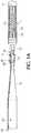
- FIG. 1Ais a side view of an exemplary fuse heating detachment system in accordance with the present invention for delivery of a vaso-occlusive device, typically a helical embolic coil 5 formed by a series of loops/windings defining a coil lumen 25.
- a vaso-occlusive devicetypically a helical embolic coil 5 formed by a series of loops/windings defining a coil lumen 25.
- the present inventive detachment systemis not limited to embolic coils, but instead is equally suited for any type or shape vaso-occlusive device.
- Embolic coil 5has a proximal coil junction 10 located at its proximal end.
- Proximal coil junction 10is a joint, preferably made out of at least one of an adhesive, an epoxy and/or a polymer.
- the joint made of adhesive, epoxy and/or polymeris of relatively low strength and/or relatively low durometer. That is, the relatively low strength of the epoxy/adhesive, or the relatively low durometer of the polymer used to fill that junction (which is related to its tear-out strength) is preferably less than the buckling strength of a delivery catheter used to implant the vaso-occlusive device in a blood vessel.
- a loop, ring or eyelet 35extends in a proximal direction from the proximal coil junction 10 of the embolic coil 5. Preferably, only a single loop, ring or eyelet is provided on the embolic coil.
- a distal end of the embolic coil 5is closed off by a distal bead 15.
- One or more stretch resistant (SR) members 20, e.g., suture filaments, disposed in the coil lumen 25provide stretch resistance when excessive pulling forces are applied to the embolic coil 5 during implantation in a patient.
- SRstretch resistant
- each stretch resistant member 20extends longitudinally the entire length of the coil lumen 25 secured at its respective ends by the proximal coil junction 10 and distal bead 15 to minimize excessive elongation.
- embolic coil 5is advanced via a delivery catheter 80 to a target site in the body (e.g., within the blood vessel).
- a target site in the bodye.g., within the blood vessel.
- Corewire 45has a stiffer proximal section proximate its proximal end compared to its more flexible distal section proximate its distal end.
- the corewire 45 needed to advance the delivery system through distal tortuosityis achieved by providing tapers over its distal section wherein the tapers may be ground, and wherein the length and/or number of tapers determines the flexibility of the distal section.
- the corewireis made from any biocompatible electrically conductive material such as stainless steel or Nitonal.
- Corewire 45may be made either as an integrated single piece construction throughout or, alternatively, as a two-piece construction secured, attached, connected or mounted together.
- the proximal section of the corewiremay be a first material (e.g., stainless steel), while the distal section connected to the proximal section may be made of a second material (e.g., Nitonal) different than the first material.
- a non-conductive coating (e.g., insulation sleeve) 55is disposed about the exterior of the corewire 45. Attached, secured, connected or otherwise mounted to its outer surface and extending preferably the length of the corewire 45 is a separate insulated electrically conductive wire 60.
- a heating fuse element 30 having a given resistivity such as an electrical conductive wire or electrical conductive stripis preferably configured as a segment having two terminating ends.
- heating fuse element 30is substantially U-shaped or hemispherical. Any other shape is contemplated and within the intended scope of the present invention so long as the heating fuse element 30 is configured as a segment having two terminating ends.
- heating fuse element 30has a failure section 65 substantially midway between its terminating ends. Failure section 65 is a mechanically induced deformation and/or reduced diameter (e.g., thinner) cross-section to further increase the localized electrical resistance in this section of the heating fuse element thereby narrowing or targeting the location in which the heating fuse element melts and/or severs.
- One terminating end 40 of the heating fuse element 30is electrically connected directly to the distal end of the corewire 45 forming a first electrical connection joint 70.
- An inner insulation sleeve 83 made of an electrically non-conductive materialis placed over a distal section of the corewire disposed between the insulation sleeve 55 and electrically conductive wire 60.
- the inner insulation sleeve 83protects the first electrical connection joint 70 while also preventing an electrical connection between the second terminating end 50 of the heating fuse element 30 and the corewire 45.
- the second terminating end 50 of the heating fuse element 30is threaded through the loop 35 of the embolic coil 5.
- An electrical circuitis completed or closed by electrically connecting the second terminating end 50 of the heating fuse element 30 directly to a stripped distal end of the insulated electrical wire 60 forming a second electrical connection joint 75.
- An outer insulation sleeve 85also made of an electrically non-conductive material, is placed over at least a portion of the insulated conductive wire 60, the inner insulation sleeve 83 and the corewire 45. The outer insulation sleeve 85 secures the second electrical connection joint 75 to the insulated conductive wire 60 while protecting the second electrical connection joint 75 itself. Either the same or different electrically non-conductive materials may be used for the inner and outer insulation sleeves 83, 85.
- a power supply 90e.g., a battery
- the conductorsi.e., proximal ends of corewire 45 and insulated electrically conductive wire 60
- Each of the first and second electrical connection joints 70, 75may be established via solder, welding, conductive epoxy or any other electrical joint connection.
- the first terminating end 40 of the heating fuse element 30is electrically connected to the corewire 45 proximate its distal end thereby forming the first electrical joint 70.
- Inner insulation sleeve 83is positioned over a distal section of the electrically conductive corewire 45 while also covering the first electrical connection joint 70.
- the second terminating end of 50 of the heating fuse element 30is then threaded through the loop 35 of the embolic coil 5. Once threaded through the loop 35, the second terminating end 50 of the heating fuse element 30 is electrically connected to the insulated electrically conductive wire 60 at the second electrical connection joint 75.
- the outer insulation sleeve 85is positioned over a distal section of the assembly (including the insulated electrically conductive wire 60, the inner insulation sleeve 83 and the electrically conductive corewire 45) and is also positioned to cover the second electrical connection joint 75.
- the vasculature occlusion device 5is advanced via the delivery catheter 80 to a target site in a human body.
- electrical activation of the heating element 30 by the power source (e.g., a battery) 90increases the electrical resistance therein. Due to its design, the resistance is greatest in the failure section 65 of the heating fuse element 30.
- the present inventive detachment systemadvantageously minimizes the length (as measured from approximately its midsection to one of its terminating ends) of the heating fuse element 30.
- such length of the heating fuse elementmay be reduced to a range between approximately 1.0 mm to approximate 3.0 mm, preferably approximately 2mm.
- the heating fuse element 30is desirably sufficiently long (as measured in an axial direction) to produce sufficient resistance when the embolic coil 5 is implanted. While on the other hand, the length of the heating fuse element 30 is sufficiently short to minimize micro-catheter kick back (i.e., push back out of aneurysm). A shorter length heating fuse element also optimizes the flexibility of the distal end of the coil delivery system desirable during delivery of the vaso-occulsive device to the target site in the human body.
- the corewireserves as one of the electrical conductors and the insulated electrically conductive wire as the other electrical conductor in forming a closed loop electrical path along with the power supply and heating fuse element.
- the corewirealso serves the dual function of advancing the vaso-occlusive device in the delivery catheter.
- a sufficient resistanceis produced in the heating fuse element that melts and/or severs at least a section thereof (e.g., the failure section 65) thereby releasing the embolic coil at a target site within the body.
- the present inventionhas been shown and described for delivery and detachment of an embolic coil.
- Other vaso-occlusive devicesare contemplated and within the scope of the present invention.
Landscapes
- Health & Medical Sciences (AREA)
- Surgery (AREA)
- Life Sciences & Earth Sciences (AREA)
- Engineering & Computer Science (AREA)
- Molecular Biology (AREA)
- Animal Behavior & Ethology (AREA)
- Veterinary Medicine (AREA)
- Biomedical Technology (AREA)
- Heart & Thoracic Surgery (AREA)
- Medical Informatics (AREA)
- Public Health (AREA)
- Nuclear Medicine, Radiotherapy & Molecular Imaging (AREA)
- General Health & Medical Sciences (AREA)
- Reproductive Health (AREA)
- Vascular Medicine (AREA)
- Neurosurgery (AREA)
- Surgical Instruments (AREA)
- Physics & Mathematics (AREA)
- Plasma & Fusion (AREA)
- Otolaryngology (AREA)
Description
- The present invention relates to vasculature occlusive devices (e.g., embolic coils) for implantation within a blood vessel of a body. In particular, the present invention relates to an improved heating detachment system for an embolic coil delivery system in the treatment of blood vessel disorders.
- Vascular disorders and defects such as aneurysms and other arterio-venous malformations are especially difficult to treat when located near critical tissues or where ready access to malformation is not available. Both difficulty factors apply especially to cranial aneurysms. Due to the sensitive brain tissue surrounding cranial blood vessels and the restricted access, it is very challenging and often risky to surgically treat defects of the cranial vasculature.
- Alternative treatments include vasculature occlusion devices, such as embolic coils, deployed using catheter delivery systems. In such systems used to treat cranial aneurysms, the distal end of an embolic coil delivery catheter is inserted into non-cranial vasculature of a patient, typically through a femoral artery in the groin, and guided to a predetermined delivery site within the cranium.
- Multiple embolic coils of various lengths, generally approximately 1 cm to as long as approximately 100 cm, and preselected stiffness often are packed sequentially within a cranial aneurysm to limit blood flow therein and to encourage embolism formation. Typically, physicians first utilize stiffer coils to establish a framework within the aneurysm and then select more flexible coils to fill spaces within the framework. Ideally, each coil conforms both to the aneurysm and to previously implanted coils. Each successive coil is selected individually based on factors including stiffness, length, and preformed shape which the coil will tend to assume after delivery.
- During implantation, the physician manipulates each embolic coil until it is in a satisfactory position, as seen by an imaging technique such as fluoroscopic visualization, before detaching the coil from the delivery system. It is beneficial for both ends of each coil to remain positioned within the aneurysm after delivery; otherwise, a length of coil protruding into the main lumen of the blood vessel invites undesired clotting external to the aneurysm. After each successive coil is detached, the next coil is subject to an increasing risk of becoming entangled in the growing mass of coils, thereby restricting the depth of insertion for that coil into the aneurysm.
- Difficulties may arise due to stretching of the embolic coils during repositioning or attempted retrieval of the coils, especially if the coil becomes entangled and complete insertion of the coil into the aneurysm is not accomplished. If pulling forces applied to a coil exceed its elastic limit, the coil will not return to its original shape. A stretched coil exhibits diminished pushability or retractability, and becomes more difficult to manipulate into an optimal position or to be removed. Moreover, a stretched coil occupies less volume than an unstretched coil, which increases the number of coils needed to sufficiently pack the aneurysm to encourage formation of a robust embolus positioned wholly within the aneurysm.
To avoid such problems stretch resistance devices are used, such as that disclosed inUS Patent No. 5,853,418 , having a primary coil and an elongated stretch-resisting member fixedly attached to the primary coil in at least two locations. - In order to deliver the vaso-occlusive coils to a desired site, e.g., an aneurysm, in the vasculature, it is well-known to first position a relatively small profile, delivery catheter or micro-catheter at the targeted site using fluoroscopy, ultrasound, or other method of steerable navigation. A delivery or "pusher" wire is then passed through a proximal end of the catheter lumen, until a vaso-occlusive coil coupled to a distal end of the pusher wire is extended out of the distal end opening of the catheter and into the blood vessel at the targeted site. The vaso-occlusive device is then released or detached from the end pusher wire, and the pusher wire is withdrawn in a proximal direction back through the catheter. Depending on the particular needs of the patient, another occlusive device may then be pushed through the catheter and released at the same site in a similar manner.
- Several conventional methods are used to detach the wire from the embolic coil once it has been properly positioned at the targeted site in the blood vessel using a delivery catheter. One known way to release a vaso-occlusive coil from the end of the pusher wire is through the use of an electrolytically severable junction, which is an exposed section or detachment zone located along a distal end portion of the pusher wire. The detachment zone is typically made of stainless steel and is located just proximal of the vaso-occlusive device. An electrolytically severable junction is susceptible to electrolysis and disintegrates when the pusher wire is electrically charged in the presence of an ionic solution, such as blood or other bodily fluids. Thus, once the detachment zone exits out of the catheter distal end and is exposed in the vessel blood pool of the patient, a current applied to the conductive pusher wire completes a circuit with an electrode attached to the patient's skin, or with a conductive needle inserted through the skin at a remote site, and the detachment zone disintegrates due to electrolysis.
- One disadvantage of occlusive devices that are deployed using electrolytic detachment is that the electrolytic process requires a certain amount of time to elapse to effectuate release of the occlusive element. This time lag is also disadvantageous for occlusive delivery devices that utilize thermal detachment such as that described in
US Patent No. 6,966,892 . - Another conventional detachment technique during delivery of a vaso-occlusive device involves the use of fluid pressure (e.g., hydraulic detachment) to release an embolic coil once it is properly positioned, as described in
US Patent Nos. 6,063,100 and6,179,857 . - The main problems associated with current detachment schemes are reliability of detachment, speed of detachment, convenience of detaching mechanism (e.g., hydraulic detachment requires a high pressure syringe, while electrolytic detachment requires a battery operated box), and length/stiffness of the distal section.
- It is therefore desirable to develop an improved heating detachment system for a vaso-occlusive device (e.g., an embolic coil device) that solves the aforementioned problems associated with conventional devices.
US 2014/0277092 A1 discloses a vaso-occlusive delivery assembly including a pusher assembly having proximal and distal ends, a conductive sacrificial link disposed at the distal end of the pusher assembly, and a vaso-occlusive device secured to the pusher assembly by the sacrificial link. - An aspect of the present invention relates to an improved heating detachment system for delivery of a vaso-occlusive device that is simpler, more reliable, quicker, more convenient and having a reduced length rigid distal section than that of conventional mechanical detachment systems.
- Another aspect of the present invention is directed to an improved detachment system for delivery of a vaso-occlusive device that optimizes distal flexibility, placement at a desired treatment site and detachment characteristics.
- Still another aspect of the present invention relates to a vasculature occlusion device detachment system including a heating fuse element having a predetermined resistivity, a first terminating end and an opposite second terminating end. The heating fuse element is made of a material that melts when a current is applied that exceeds a predetermined maximum current threshold. The system further includes an electrically conductive corewire electrically connected proximate its distal end directly to the first terminating end of the heating fuse element at a first electrical connection joint, the electrically conductive corewire being tapered over its distal section. An insulated electrically conductive wire separate from the electrically conductive corewire is electrically connected directly to the second terminating end of the heating fuse element at a second electrical connection joint. An inner insulation sleeve made from an electrical non-conductive material is placed over a distal section of the corewire and covers the first electrical connection joint. The inner insulation sleeve is disposed between the insulated electrically conductive wire and the electrically conductive corewire. An outer insulation sleeve made from an electrical non-conductive material is disposed over a distal section of an assembly including the insulated electrically conductive wire, the inner insulation sleeve and the electrically conductive corewire. The outer insulation sleeve covers the second electrical connection joint.
- Yet another aspect of the present invention is directed to a method of manufacturing the vasculature occlusion device detachment system in the preceding paragraph. The first terminating end of the heating fuse element is electrically connected directly to the electrically conductive corewire proximate its distal end at the first electrical connection joint. Next, the inner insulation sleeve is positioned over a distal section of the electrically conductive corewire and covering the first electrical connection joint. The second terminating end of the heating fuse element is threaded through the loop of the vasculature occlusion device. A second electrical connection joint is formed by electrically connecting the second terminating end of the heating fuse element to the insulated electrically conductive wire at the second electrical connection joint. The outer insulation sleeve is positioned over a distal section of the assembly and covering the second electrical connection joint.
- The foregoing and other features of the present invention will be more readily apparent from the following detailed description and drawings of illustrative of the invention wherein like reference numbers refer to similar elements throughout the several views and in which:
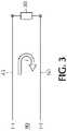
Figure 1A is a side view of the present inventive fuse heating detachment system for an embolic coil, with a cross-sectional portion of the embolic coil showing the interior thereof;Figure 1B is a side view of the delivery catheter with the present inventive fuse heating detachment system for an embolic coil assembled therein;Figure 2A is an enlarged top view of the heating fuse element with reduced localized cross-section, in a closed state prior to activation and application of a current;Figure 2B is an enlarged top view of the heating fuse element ofFigure 2A , in an open state, after activation of an applied current; andFigure 3 is a schematic electric circuit diagram illustrating a closed loop formed by the power supply, electrically conductive corewire, the insulated electrically conductive wire and the heating fuse element.- The terms "proximal"/"proximally" and "distal"/"distally" refer to a direction closer to or away from, respectively, an operator (e.g., surgeon, physician, nurse, technician, etc.) who would insert the medical device into the patient, with the tip-end (i.e., distal end or leading end) of the device inserted inside a patient's body. Thus, for example, a "proximal direction" would refer to the direction towards the operator, whereas "distal direction" would refer to the direction away from the operator towards the leading or tip-end of the medical device.
- By way of illustrative example only, the present inventive heating detachment system is utilized for delivery of an embolic component, e.g., embolic helical coil. It is, however, intended and within the scope of the present invention to use the present inventive heating detachment system with any type of vaso-occlusive device.
Figure 1A is a side view of an exemplary fuse heating detachment system in accordance with the present invention for delivery of a vaso-occlusive device, typically a helicalembolic coil 5 formed by a series of loops/windings defining acoil lumen 25. The present inventive detachment system is not limited to embolic coils, but instead is equally suited for any type or shape vaso-occlusive device.Embolic coil 5 has aproximal coil junction 10 located at its proximal end.Proximal coil junction 10 is a joint, preferably made out of at least one of an adhesive, an epoxy and/or a polymer. Most preferably, the joint made of adhesive, epoxy and/or polymer is of relatively low strength and/or relatively low durometer. That is, the relatively low strength of the epoxy/adhesive, or the relatively low durometer of the polymer used to fill that junction (which is related to its tear-out strength) is preferably less than the buckling strength of a delivery catheter used to implant the vaso-occlusive device in a blood vessel. A loop, ring oreyelet 35 extends in a proximal direction from theproximal coil junction 10 of theembolic coil 5. Preferably, only a single loop, ring or eyelet is provided on the embolic coil. Opposite its proximal end, a distal end of theembolic coil 5 is closed off by adistal bead 15. One or more stretch resistant (SR)members 20, e.g., suture filaments, disposed in thecoil lumen 25 provide stretch resistance when excessive pulling forces are applied to theembolic coil 5 during implantation in a patient. Preferably, each stretchresistant member 20 extends longitudinally the entire length of thecoil lumen 25 secured at its respective ends by theproximal coil junction 10 anddistal bead 15 to minimize excessive elongation.- Referring to
Figure 1B , using a corewire or pusher,embolic coil 5 is advanced via adelivery catheter 80 to a target site in the body (e.g., within the blood vessel). In contrast to conventional pusher members having a central lumen, there is no central lumen defined longitudinally through the corewire of the present invention.Corewire 45 has a stiffer proximal section proximate its proximal end compared to its more flexible distal section proximate its distal end. As is illustrated inFigure 1B , flexibility of thecorewire 45 needed to advance the delivery system through distal tortuosity is achieved by providing tapers over its distal section wherein the tapers may be ground, and wherein the length and/or number of tapers determines the flexibility of the distal section. Thus, the length and/or number of tapers shown in the drawings are merely for illustrative purposes only and may be adapted, as desired. The corewire is made from any biocompatible electrically conductive material such as stainless steel or Nitonal.Corewire 45 may be made either as an integrated single piece construction throughout or, alternatively, as a two-piece construction secured, attached, connected or mounted together. For instance, the proximal section of the corewire may be a first material (e.g., stainless steel), while the distal section connected to the proximal section may be made of a second material (e.g., Nitonal) different than the first material. A non-conductive coating (e.g., insulation sleeve) 55 is disposed about the exterior of thecorewire 45. Attached, secured, connected or otherwise mounted to its outer surface and extending preferably the length of thecorewire 45 is a separate insulated electricallyconductive wire 60. - A
heating fuse element 30 having a given resistivity such as an electrical conductive wire or electrical conductive strip is preferably configured as a segment having two terminating ends. Typically,heating fuse element 30 is substantially U-shaped or hemispherical. Any other shape is contemplated and within the intended scope of the present invention so long as theheating fuse element 30 is configured as a segment having two terminating ends. Preferably,heating fuse element 30 has afailure section 65 substantially midway between its terminating ends.Failure section 65 is a mechanically induced deformation and/or reduced diameter (e.g., thinner) cross-section to further increase the localized electrical resistance in this section of the heating fuse element thereby narrowing or targeting the location in which the heating fuse element melts and/or severs. - One terminating
end 40 of theheating fuse element 30 is electrically connected directly to the distal end of thecorewire 45 forming a first electrical connection joint 70. Aninner insulation sleeve 83 made of an electrically non-conductive material is placed over a distal section of the corewire disposed between theinsulation sleeve 55 and electricallyconductive wire 60. Theinner insulation sleeve 83 protects the first electrical connection joint 70 while also preventing an electrical connection between the second terminatingend 50 of theheating fuse element 30 and thecorewire 45. The second terminatingend 50 of theheating fuse element 30 is threaded through theloop 35 of theembolic coil 5. An electrical circuit is completed or closed by electrically connecting the second terminatingend 50 of theheating fuse element 30 directly to a stripped distal end of the insulatedelectrical wire 60 forming a second electrical connection joint 75. Anouter insulation sleeve 85, also made of an electrically non-conductive material, is placed over at least a portion of the insulatedconductive wire 60, theinner insulation sleeve 83 and thecorewire 45. Theouter insulation sleeve 85 secures the second electrical connection joint 75 to the insulatedconductive wire 60 while protecting the second electrical connection joint 75 itself. Either the same or different electrically non-conductive materials may be used for the inner andouter insulation sleeves Figure 3 , a power supply 90 (e.g., a battery) is connected across the conductors (i.e., proximal ends ofcorewire 45 and insulated electrically conductive wire 60) producing a current across the resistiveheating fuse element 30 thereby increasing the electrical resistance therein. Each of the first and second electrical connection joints 70, 75 may be established via solder, welding, conductive epoxy or any other electrical joint connection. - In operation, the first terminating
end 40 of theheating fuse element 30 is electrically connected to thecorewire 45 proximate its distal end thereby forming the first electrical joint 70.Inner insulation sleeve 83 is positioned over a distal section of the electrically conductive corewire 45 while also covering the first electrical connection joint 70. The second terminating end of 50 of theheating fuse element 30 is then threaded through theloop 35 of theembolic coil 5. Once threaded through theloop 35, the second terminatingend 50 of theheating fuse element 30 is electrically connected to the insulated electricallyconductive wire 60 at the second electrical connection joint 75. Next, theouter insulation sleeve 85 is positioned over a distal section of the assembly (including the insulated electricallyconductive wire 60, theinner insulation sleeve 83 and the electrically conductive corewire 45) and is also positioned to cover the second electrical connection joint 75. Now that the delivery device has been assembled, using the electricallyconductive corewire 45 thevasculature occlusion device 5 is advanced via thedelivery catheter 80 to a target site in a human body. Once theembolic coil 5 has been properly positioned at a desired treatment site within the blood vessel, electrical activation of theheating element 30 by the power source (e.g., a battery) 90 increases the electrical resistance therein. Due to its design, the resistance is greatest in thefailure section 65 of theheating fuse element 30. An increase in the resistance in thefailure section 65 beyond the predetermined threshold tolerance of the material causes thefailure section 65 of theheating fuse element 30 to melt and thus sever thereby releasing theembolic coil 5 secured therein. Thereafter, thedelivery catheter 80, corewire 45, insulated electricallyconductive wire 60 andheating element 30 are withdrawn from the human body by pulling in a proximal direction leaving in place theembolic coil 5 within the blood vessel at its desired treatment site. - The present inventive detachment system advantageously minimizes the length (as measured from approximately its midsection to one of its terminating ends) of the
heating fuse element 30. For example, with this alternative embodiment such length of the heating fuse element may be reduced to a range between approximately 1.0 mm to approximate 3.0 mm, preferably approximately 2mm. - Additional design factors or considerations are contemplated other than that of maximizing heat transfer to the coil securing suture. On the one hand, the
heating fuse element 30 is desirably sufficiently long (as measured in an axial direction) to produce sufficient resistance when theembolic coil 5 is implanted. While on the other hand, the length of theheating fuse element 30 is sufficiently short to minimize micro-catheter kick back (i.e., push back out of aneurysm). A shorter length heating fuse element also optimizes the flexibility of the distal end of the coil delivery system desirable during delivery of the vaso-occulsive device to the target site in the human body. - In accordance with the present invention, the corewire serves as one of the electrical conductors and the insulated electrically conductive wire as the other electrical conductor in forming a closed loop electrical path along with the power supply and heating fuse element. Preferably, the corewire also serves the dual function of advancing the vaso-occlusive device in the delivery catheter. In response to current provided by the power supply a sufficient resistance is produced in the heating fuse element that melts and/or severs at least a section thereof (e.g., the failure section 65) thereby releasing the embolic coil at a target site within the body.
- The present invention has been shown and described for delivery and detachment of an embolic coil. Other vaso-occlusive devices are contemplated and within the scope of the present invention.
- Thus, while there have been shown, described, and pointed out fundamental novel features of the invention as applied to a preferred embodiment thereof, it will be understood that various omissions, substitutions, and changes in the form and details of the devices illustrated, and in their operation, may be made by those skilled in the art without departing from the scope of the invention. For example, it is expressly intended that all combinations of those elements and/or steps that perform substantially the same function, in substantially the same way, to achieve the same results be within the scope of the disclosure. Substitutions of elements from one described embodiment to another are also fully intended and contemplated. It is also to be understood that the drawings are not necessarily drawn to scale, but that they are merely conceptual in nature. It is the intention, therefore, to be limited only as indicated by the scope of the claims appended hereto.
Claims (12)
- A detachment system comprising:a heating fuse element (30) having a predetermined resistivity; the heating fuse element having a first terminating end (40) and an opposite second terminating end (50); the heating fuse element being made of a material that melts or severs when an applied current exceeds a predetermined maximum current threshold;an electrically conductive corewire (45) having a proximal end and an opposite distal end; the electrically conductive corewire being electrically connected proximate its distal end directly to the first terminating end of the heating fuse element at a first electrical connection joint (70); andan insulated electrically conductive wire (60) separate from the electrically conductive corewire; the insulated electrically conductive wire having a proximal end and an opposite distal end; the distal end of the insulated electrically conductive wire being electrically connected directly to the second terminating end of the heating fuse element at a second electrical connection joint (75);an inner insulation sleeve (83) made from an electrical non-conductive material; the inner insulation sleeve is disposed over a distal section of the corewire and covers the first electrical connection joint; the inner insulation sleeve is disposed between the insulated electrically conductive wire and the electrically conductive corewire; andan outer insulation sleeve (85) made from an electrical non-conductive material; the outer insulation sleeve is disposed over a distal section of an assembly including the insulated electrically conductive wire, the inner insulation sleeve and the electrically conductive corewire; the outer insulation sleeve covers the second electrical connection joint,characterised in that the electrically conductive corewire is tapered over its distal section.
- The system in accordance with claim 1, further comprising a power source (90) electrically connected to the respective proximal ends of the electrically conductive corewire and the insulated electrically conductive wire.
- The system in accordance with claim 1, wherein the heating fuse element is a conductive wire or a conductive strip.
- The system in accordance with claim 1, wherein i) the electrically conductive corewire is tapered from its proximal end towards is distal end, or ii) the electrically conductive corewire does not have a lumen defined therein.
- The system in accordance with claim 1, further comprising a vasculature occlusion device (5) having a proximal end and an opposite distal end; a loop (35) protruding in a proximal direction from the proximal end of the vasculature occlusion device; the heating fuse element being threaded through the loop.
- The system in accordance with claim 1, wherein the heating fuse element is U-shaped or hemispherical in shape.
- The system in accordance with claim 1, wherein the length of the heating fuse element measured from approximately its midsection to one of its terminating ends is between approximately 1 mm and approximately 3 mm.
- The system in accordance with claim 1, wherein the heating fuse element has a failure section (65) approximately midway between the first terminating end and the second terminating end; the failure section of the heating fuse element having a mechanically induced deformation and/or reduced diameter cross-section to induce failure therein.
- A method of assembling the detachment system in accordance with claim 5, comprising the steps of:electrically connecting the first terminating end of the heating fuse element to the electrically conductive corewire proximate its distal end at the first electrical connection joint;positioning the inner insulation sleeve over a distal section of the electrically conductive corewire and covering the first electrical connection joint;threading the second terminating end of the heating fuse element through the loop of the vasculature occlusion device;electrically connecting the second terminating end of the heating fuse element to the insulated electrically conductive wire at the second electrical connection joint; andpositioning the outer insulation sleeve over a distal section of the assembly and covering the second electrical connection joint.
- The method in accordance with claim 9, wherein the heating fuse element is U-shaped or hemispherical in shape.
- The method in accordance with claim 9, wherein the length of the heating fuse element measured from its midsection to one of its terminating ends is between approximately 1 mm and approximately 3 mm.
- The method in accordance with claim 9, wherein the heating fuse element has a failure section approximately midway between the first terminating end and the second terminating end; the failure section of the heating fuse element having a mechanically induced deformation and/or reduced diameter cross-section to induce failure therein.
Priority Applications (1)
| Application Number | Priority Date | Filing Date | Title |
|---|---|---|---|
| EP20183939.6AEP3738528A1 (en) | 2014-09-19 | 2015-09-18 | A vasculature occlusion device detachment system with tapered corewire and single loop fuse detachment |
Applications Claiming Priority (1)
| Application Number | Priority Date | Filing Date | Title |
|---|---|---|---|
| US14/491,145US9855050B2 (en) | 2014-09-19 | 2014-09-19 | Vasculature occlusion device detachment system with tapered corewire and single loop fuse detachment |
Related Child Applications (1)
| Application Number | Title | Priority Date | Filing Date |
|---|---|---|---|
| EP20183939.6ADivisionEP3738528A1 (en) | 2014-09-19 | 2015-09-18 | A vasculature occlusion device detachment system with tapered corewire and single loop fuse detachment |
Publications (2)
| Publication Number | Publication Date |
|---|---|
| EP2997911A1 EP2997911A1 (en) | 2016-03-23 |
| EP2997911B1true EP2997911B1 (en) | 2020-07-29 |
Family
ID=54150309
Family Applications (2)
| Application Number | Title | Priority Date | Filing Date |
|---|---|---|---|
| EP20183939.6AWithdrawnEP3738528A1 (en) | 2014-09-19 | 2015-09-18 | A vasculature occlusion device detachment system with tapered corewire and single loop fuse detachment |
| EP15185808.1AActiveEP2997911B1 (en) | 2014-09-19 | 2015-09-18 | A vasculature occlusion device detachment system with tapered corewire and heater activated detachment |
Family Applications Before (1)
| Application Number | Title | Priority Date | Filing Date |
|---|---|---|---|
| EP20183939.6AWithdrawnEP3738528A1 (en) | 2014-09-19 | 2015-09-18 | A vasculature occlusion device detachment system with tapered corewire and single loop fuse detachment |
Country Status (9)
| Country | Link |
|---|---|
| US (1) | US9855050B2 (en) |
| EP (2) | EP3738528A1 (en) |
| JP (2) | JP6768276B2 (en) |
| KR (1) | KR102525250B1 (en) |
| CN (1) | CN105434004B (en) |
| AU (1) | AU2015227530B2 (en) |
| BR (1) | BR102015023992A2 (en) |
| CA (1) | CA2904928A1 (en) |
| ES (1) | ES2818105T3 (en) |
Families Citing this family (8)
| Publication number | Priority date | Publication date | Assignee | Title |
|---|---|---|---|---|
| US10285710B2 (en)* | 2016-06-01 | 2019-05-14 | DePuy Synthes Products, Inc. | Endovascular detachment system with flexible distal end and heater activated detachment |
| US11116509B2 (en)* | 2017-11-10 | 2021-09-14 | Avantec Vascular Corporation | System and method for delivering an embolic device |
| CN113749718B (en)* | 2020-06-05 | 2024-01-26 | 微创神通医疗科技(上海)有限公司 | Release device, release system, release method and treatment device |
| CN113749717B (en)* | 2020-06-05 | 2023-09-29 | 微创神通医疗科技(上海)有限公司 | Release device, release system, release method and treatment device |
| US20220142651A1 (en)* | 2020-06-05 | 2022-05-12 | Balt Usa | Novel enhanced zero displacement optima® system |
| CN112220519A (en)* | 2020-10-23 | 2021-01-15 | 张强 | Binding belt and ligation device |
| CN116158799B (en)* | 2021-11-24 | 2025-07-25 | 上海微创心脉医疗科技(集团)股份有限公司 | Release mechanism and plug device |
| US12433620B2 (en) | 2024-02-23 | 2025-10-07 | Shockwave Medical, Inc. | Locus emitter shock wave catheter devices with increased longevity and higher sonic output |
Family Cites Families (49)
| Publication number | Priority date | Publication date | Assignee | Title |
|---|---|---|---|---|
| US5624449A (en)* | 1993-11-03 | 1997-04-29 | Target Therapeutics | Electrolytically severable joint for endovascular embolic devices |
| ATE295127T1 (en) | 1994-03-03 | 2005-05-15 | Boston Scient Ltd | DEVICE FOR DETECTING THE DIVISION OF A VASS OCCLUSION DEVICE |
| US5522836A (en)* | 1994-06-27 | 1996-06-04 | Target Therapeutics, Inc. | Electrolytically severable coil assembly with movable detachment point |
| US5522839A (en)* | 1994-09-09 | 1996-06-04 | Pilling Weck Incorporated | Dissecting forceps |
| US5578074A (en)* | 1994-12-22 | 1996-11-26 | Target Therapeutics, Inc. | Implant delivery method and assembly |
| DK175166B1 (en) | 1995-01-03 | 2004-06-21 | Cook William Europ | Method of manufacturing an assembly for placing an embolization coil in the vascular system and such assembly as well as an apparatus for advancing the assembly |
| US6013084A (en) | 1995-06-30 | 2000-01-11 | Target Therapeutics, Inc. | Stretch resistant vaso-occlusive coils (II) |
| US5853418A (en) | 1995-06-30 | 1998-12-29 | Target Therapeutics, Inc. | Stretch resistant vaso-occlusive coils (II) |
| US6156061A (en) | 1997-08-29 | 2000-12-05 | Target Therapeutics, Inc. | Fast-detaching electrically insulated implant |
| US6063100A (en) | 1998-03-10 | 2000-05-16 | Cordis Corporation | Embolic coil deployment system with improved embolic coil |
| US6478773B1 (en) | 1998-12-21 | 2002-11-12 | Micrus Corporation | Apparatus for deployment of micro-coil using a catheter |
| US6277126B1 (en) | 1998-10-05 | 2001-08-21 | Cordis Neurovascular Inc. | Heated vascular occlusion coil development system |
| US6835185B2 (en) | 1998-12-21 | 2004-12-28 | Micrus Corporation | Intravascular device deployment mechanism incorporating mechanical detachment |
| US6179857B1 (en) | 1999-02-22 | 2001-01-30 | Cordis Corporation | Stretch resistant embolic coil with variable stiffness |
| US6280457B1 (en) | 1999-06-04 | 2001-08-28 | Scimed Life Systems, Inc. | Polymer covered vaso-occlusive devices and methods of producing such devices |
| US6458127B1 (en) | 1999-11-22 | 2002-10-01 | Csaba Truckai | Polymer embolic elements with metallic coatings for occlusion of vascular malformations |
| US7740637B2 (en) | 2000-02-09 | 2010-06-22 | Micrus Endovascular Corporation | Apparatus and method for deployment of a therapeutic device using a catheter |
| US6743251B1 (en) | 2000-11-15 | 2004-06-01 | Scimed Life Systems, Inc. | Implantable devices with polymeric detachment junction |
| US6866677B2 (en) | 2001-04-03 | 2005-03-15 | Medtronic Ave, Inc. | Temporary intraluminal filter guidewire and methods of use |
| US6953473B2 (en) | 2001-12-20 | 2005-10-11 | Boston Scientific Scimed, Inc. | Detachable device with electrically responsive element |
| US7485122B2 (en) | 2002-06-27 | 2009-02-03 | Boston Scientific Scimed, Inc. | Integrated anchor coil in stretch-resistant vaso-occlusive coils |
| US7608058B2 (en) | 2002-07-23 | 2009-10-27 | Micrus Corporation | Stretch resistant therapeutic device |
| US7331973B2 (en) | 2002-09-30 | 2008-02-19 | Avdanced Cardiovascular Systems, Inc. | Guide wire with embolic filtering attachment |
| US7651513B2 (en) | 2003-04-03 | 2010-01-26 | Boston Scientific Scimed, Inc. | Flexible embolic device delivery system |
| US20050149108A1 (en) | 2003-12-17 | 2005-07-07 | Microvention, Inc. | Implant delivery and detachment system and method |
| US8398693B2 (en) | 2004-01-23 | 2013-03-19 | Boston Scientific Scimed, Inc. | Electrically actuated medical devices |
| AU2005276980B2 (en) | 2004-08-25 | 2011-04-21 | Microvention, Inc. | Thermal detachment system for implantable devices |
| JP4879025B2 (en) | 2004-10-29 | 2012-02-15 | 株式会社カネカ | Medical wire |
| US7608089B2 (en) | 2004-12-22 | 2009-10-27 | Boston Scientific Scimed, Inc. | Vaso-occlusive device having pivotable coupling |
| US20070100414A1 (en) | 2005-11-02 | 2007-05-03 | Cardiomind, Inc. | Indirect-release electrolytic implant delivery systems |
| US7582101B2 (en) | 2006-02-28 | 2009-09-01 | Cordis Development Corporation | Heated mechanical detachment for delivery of therapeutic devices |
| JP5230602B2 (en) | 2006-04-17 | 2013-07-10 | タイコ ヘルスケア グループ リミテッド パートナーシップ | System and method for mechanically positioning an endovascular implant |
| CA2680607C (en) | 2007-03-13 | 2015-07-14 | Microtherapeutics, Inc. | An implant including a coil and a stretch-resistant member |
| JP5623291B2 (en) | 2008-01-04 | 2014-11-12 | ボストン サイエンティフィック サイムド,インコーポレイテッドBoston Scientific Scimed,Inc. | Separation mechanism for implantable devices |
| JP5677955B2 (en) | 2008-09-09 | 2015-02-25 | ボストン サイエンティフィック サイムド,インコーポレイテッドBoston Scientific Scimed,Inc. | Combined desorption mechanism |
| US20100160944A1 (en)* | 2008-12-24 | 2010-06-24 | Boston Scientific Scimed, Inc. | Thermally detachable embolic assemblies |
| WO2010104955A2 (en) | 2009-03-13 | 2010-09-16 | Boston Scientific Scimed, Inc. | Electrical contact for occlusive device delivery system |
| AU2011240927B2 (en) | 2010-04-14 | 2015-07-16 | Microvention, Inc. | Implant delivery device |
| US20120209310A1 (en) | 2011-02-10 | 2012-08-16 | Stryker Nv Operations Limited | Vaso-occlusive device delivery system |
| JP5331836B2 (en)* | 2011-02-21 | 2013-10-30 | コヴィディエン リミテッド パートナーシップ | System and method for supplying and deploying an occlusion device in a conduit |
| US20120330349A1 (en) | 2011-06-27 | 2012-12-27 | Jones Donald K | Implant delivery and active release system |
| US9579104B2 (en) | 2011-11-30 | 2017-02-28 | Covidien Lp | Positioning and detaching implants |
| JP2013153810A (en) | 2012-01-27 | 2013-08-15 | Terumo Corp | Knob treatment device and knob treatment method |
| US8932318B2 (en) | 2012-03-30 | 2015-01-13 | DePuy Synthes Products, LLC | Embolic coil detachment mechanism with polymer tether |
| US9980731B2 (en)* | 2012-03-30 | 2018-05-29 | DePuy Synthes Products, Inc. | Embolic coil detachment mechanism with flexible distal member and coupling union |
| US9943313B2 (en) | 2013-01-03 | 2018-04-17 | Empirilon Technology Llc | Detachable coil release system and handle assembly |
| CN105228534B (en)* | 2013-03-14 | 2018-03-30 | 斯瑞克公司 | Vaso-Occlusive Device Delivery System |
| WO2014150824A1 (en) | 2013-03-14 | 2014-09-25 | Stryker Corporation | Vaso-occlusive device delivery system |
| CN203591293U (en) | 2013-12-04 | 2014-05-14 | 王玉峰 | Spring ring system |
- 2014
- 2014-09-19USUS14/491,145patent/US9855050B2/enactiveActive
- 2015
- 2015-09-17BRBR102015023992Apatent/BR102015023992A2/enactiveSearch and Examination
- 2015-09-18EPEP20183939.6Apatent/EP3738528A1/ennot_activeWithdrawn
- 2015-09-18AUAU2015227530Apatent/AU2015227530B2/ennot_activeCeased
- 2015-09-18EPEP15185808.1Apatent/EP2997911B1/enactiveActive
- 2015-09-18KRKR1020150132174Apatent/KR102525250B1/enactiveActive
- 2015-09-18CACA2904928Apatent/CA2904928A1/ennot_activeAbandoned
- 2015-09-18CNCN201510599740.6Apatent/CN105434004B/ennot_activeExpired - Fee Related
- 2015-09-18JPJP2015184845Apatent/JP6768276B2/ennot_activeExpired - Fee Related
- 2015-09-18ESES15185808Tpatent/ES2818105T3/enactiveActive
- 2020
- 2020-06-23JPJP2020107599Apatent/JP6992130B2/ennot_activeExpired - Fee Related
Non-Patent Citations (1)
| Title |
|---|
| None* |
Also Published As
| Publication number | Publication date |
|---|---|
| US9855050B2 (en) | 2018-01-02 |
| CN105434004B (en) | 2019-09-20 |
| EP2997911A1 (en) | 2016-03-23 |
| JP6768276B2 (en) | 2020-10-14 |
| BR102015023992A2 (en) | 2016-05-24 |
| CN105434004A (en) | 2016-03-30 |
| KR20160034221A (en) | 2016-03-29 |
| JP2016059815A (en) | 2016-04-25 |
| JP2020151543A (en) | 2020-09-24 |
| US20160081694A1 (en) | 2016-03-24 |
| AU2015227530B2 (en) | 2019-11-14 |
| CA2904928A1 (en) | 2016-03-19 |
| KR102525250B1 (en) | 2023-04-26 |
| JP6992130B2 (en) | 2022-01-13 |
| EP3738528A1 (en) | 2020-11-18 |
| AU2015227530A1 (en) | 2016-04-07 |
| ES2818105T3 (en) | 2021-04-09 |
Similar Documents
| Publication | Publication Date | Title |
|---|---|---|
| EP2997911B1 (en) | A vasculature occlusion device detachment system with tapered corewire and heater activated detachment | |
| EP3181064B1 (en) | Occlusive device delivery system with mechanical detachment | |
| JP6359664B2 (en) | Vascular occlusive device delivery system | |
| US10639043B2 (en) | Vasculature occlusion device detachment system with tapered corewire and heater activated fiber detachment | |
| US8992563B2 (en) | Delivery wire assembly for occlusive device delivery system | |
| US20100234872A1 (en) | Electrical contact for occlusive device delivery system | |
| AU2015227527A1 (en) | A vasculature occlusion device detachment system with tapered corewire and heater activated fiber detachment |
Legal Events
| Date | Code | Title | Description |
|---|---|---|---|
| PUAI | Public reference made under article 153(3) epc to a published international application that has entered the european phase | Free format text:ORIGINAL CODE: 0009012 | |
| AK | Designated contracting states | Kind code of ref document:A1 Designated state(s):AL AT BE BG CH CY CZ DE DK EE ES FI FR GB GR HR HU IE IS IT LI LT LU LV MC MK MT NL NO PL PT RO RS SE SI SK SM TR | |
| AX | Request for extension of the european patent | Extension state:BA ME | |
| 17P | Request for examination filed | Effective date:20160923 | |
| RBV | Designated contracting states (corrected) | Designated state(s):AL AT BE BG CH CY CZ DE DK EE ES FI FR GB GR HR HU IE IS IT LI LT LU LV MC MK MT NL NO PL PT RO RS SE SI SK SM TR | |
| GRAJ | Information related to disapproval of communication of intention to grant by the applicant or resumption of examination proceedings by the epo deleted | Free format text:ORIGINAL CODE: EPIDOSDIGR1 | |
| STAA | Information on the status of an ep patent application or granted ep patent | Free format text:STATUS: GRANT OF PATENT IS INTENDED | |
| GRAP | Despatch of communication of intention to grant a patent | Free format text:ORIGINAL CODE: EPIDOSNIGR1 | |
| INTG | Intention to grant announced | Effective date:20170713 | |
| RIN1 | Information on inventor provided before grant (corrected) | Inventor name:LORENZO, JUAN A. Inventor name:SLAZAS, ROBERT | |
| GRAJ | Information related to disapproval of communication of intention to grant by the applicant or resumption of examination proceedings by the epo deleted | Free format text:ORIGINAL CODE: EPIDOSDIGR1 | |
| STAA | Information on the status of an ep patent application or granted ep patent | Free format text:STATUS: REQUEST FOR EXAMINATION WAS MADE | |
| INTC | Intention to grant announced (deleted) | ||
| STAA | Information on the status of an ep patent application or granted ep patent | Free format text:STATUS: EXAMINATION IS IN PROGRESS | |
| 17Q | First examination report despatched | Effective date:20171220 | |
| GRAP | Despatch of communication of intention to grant a patent | Free format text:ORIGINAL CODE: EPIDOSNIGR1 | |
| STAA | Information on the status of an ep patent application or granted ep patent | Free format text:STATUS: GRANT OF PATENT IS INTENDED | |
| INTG | Intention to grant announced | Effective date:20191002 | |
| GRAJ | Information related to disapproval of communication of intention to grant by the applicant or resumption of examination proceedings by the epo deleted | Free format text:ORIGINAL CODE: EPIDOSDIGR1 | |
| STAA | Information on the status of an ep patent application or granted ep patent | Free format text:STATUS: EXAMINATION IS IN PROGRESS | |
| INTC | Intention to grant announced (deleted) | ||
| GRAP | Despatch of communication of intention to grant a patent | Free format text:ORIGINAL CODE: EPIDOSNIGR1 | |
| STAA | Information on the status of an ep patent application or granted ep patent | Free format text:STATUS: GRANT OF PATENT IS INTENDED | |
| INTG | Intention to grant announced | Effective date:20200324 | |
| RIN1 | Information on inventor provided before grant (corrected) | Inventor name:LORENZO, JUAN A. Inventor name:SLAZAS, ROBERT | |
| GRAS | Grant fee paid | Free format text:ORIGINAL CODE: EPIDOSNIGR3 | |
| GRAA | (expected) grant | Free format text:ORIGINAL CODE: 0009210 | |
| STAA | Information on the status of an ep patent application or granted ep patent | Free format text:STATUS: THE PATENT HAS BEEN GRANTED | |
| AK | Designated contracting states | Kind code of ref document:B1 Designated state(s):AL AT BE BG CH CY CZ DE DK EE ES FI FR GB GR HR HU IE IS IT LI LT LU LV MC MK MT NL NO PL PT RO RS SE SI SK SM TR | |
| REG | Reference to a national code | Ref country code:CH Ref legal event code:EP | |
| REG | Reference to a national code | Ref country code:DE Ref legal event code:R096 Ref document number:602015056427 Country of ref document:DE | |
| REG | Reference to a national code | Ref country code:AT Ref legal event code:REF Ref document number:1294887 Country of ref document:AT Kind code of ref document:T Effective date:20200815 | |
| REG | Reference to a national code | Ref country code:IE Ref legal event code:FG4D | |
| REG | Reference to a national code | Ref country code:LT Ref legal event code:MG4D | |
| REG | Reference to a national code | Ref country code:NL Ref legal event code:MP Effective date:20200729 | |
| REG | Reference to a national code | Ref country code:AT Ref legal event code:MK05 Ref document number:1294887 Country of ref document:AT Kind code of ref document:T Effective date:20200729 | |
| PG25 | Lapsed in a contracting state [announced via postgrant information from national office to epo] | Ref country code:FI Free format text:LAPSE BECAUSE OF FAILURE TO SUBMIT A TRANSLATION OF THE DESCRIPTION OR TO PAY THE FEE WITHIN THE PRESCRIBED TIME-LIMIT Effective date:20200729 Ref country code:SE Free format text:LAPSE BECAUSE OF FAILURE TO SUBMIT A TRANSLATION OF THE DESCRIPTION OR TO PAY THE FEE WITHIN THE PRESCRIBED TIME-LIMIT Effective date:20200729 Ref country code:PT Free format text:LAPSE BECAUSE OF FAILURE TO SUBMIT A TRANSLATION OF THE DESCRIPTION OR TO PAY THE FEE WITHIN THE PRESCRIBED TIME-LIMIT Effective date:20201130 Ref country code:LT Free format text:LAPSE BECAUSE OF FAILURE TO SUBMIT A TRANSLATION OF THE DESCRIPTION OR TO PAY THE FEE WITHIN THE PRESCRIBED TIME-LIMIT Effective date:20200729 Ref country code:HR Free format text:LAPSE BECAUSE OF FAILURE TO SUBMIT A TRANSLATION OF THE DESCRIPTION OR TO PAY THE FEE WITHIN THE PRESCRIBED TIME-LIMIT Effective date:20200729 Ref country code:GR Free format text:LAPSE BECAUSE OF FAILURE TO SUBMIT A TRANSLATION OF THE DESCRIPTION OR TO PAY THE FEE WITHIN THE PRESCRIBED TIME-LIMIT Effective date:20201030 Ref country code:BG Free format text:LAPSE BECAUSE OF FAILURE TO SUBMIT A TRANSLATION OF THE DESCRIPTION OR TO PAY THE FEE WITHIN THE PRESCRIBED TIME-LIMIT Effective date:20201029 Ref country code:NO Free format text:LAPSE BECAUSE OF FAILURE TO SUBMIT A TRANSLATION OF THE DESCRIPTION OR TO PAY THE FEE WITHIN THE PRESCRIBED TIME-LIMIT Effective date:20201029 Ref country code:AT Free format text:LAPSE BECAUSE OF FAILURE TO SUBMIT A TRANSLATION OF THE DESCRIPTION OR TO PAY THE FEE WITHIN THE PRESCRIBED TIME-LIMIT Effective date:20200729 | |
| PG25 | Lapsed in a contracting state [announced via postgrant information from national office to epo] | Ref country code:RS Free format text:LAPSE BECAUSE OF FAILURE TO SUBMIT A TRANSLATION OF THE DESCRIPTION OR TO PAY THE FEE WITHIN THE PRESCRIBED TIME-LIMIT Effective date:20200729 Ref country code:PL Free format text:LAPSE BECAUSE OF FAILURE TO SUBMIT A TRANSLATION OF THE DESCRIPTION OR TO PAY THE FEE WITHIN THE PRESCRIBED TIME-LIMIT Effective date:20200729 Ref country code:LV Free format text:LAPSE BECAUSE OF FAILURE TO SUBMIT A TRANSLATION OF THE DESCRIPTION OR TO PAY THE FEE WITHIN THE PRESCRIBED TIME-LIMIT Effective date:20200729 Ref country code:IS Free format text:LAPSE BECAUSE OF FAILURE TO SUBMIT A TRANSLATION OF THE DESCRIPTION OR TO PAY THE FEE WITHIN THE PRESCRIBED TIME-LIMIT Effective date:20201129 | |
| PG25 | Lapsed in a contracting state [announced via postgrant information from national office to epo] | Ref country code:NL Free format text:LAPSE BECAUSE OF FAILURE TO SUBMIT A TRANSLATION OF THE DESCRIPTION OR TO PAY THE FEE WITHIN THE PRESCRIBED TIME-LIMIT Effective date:20200729 | |
| REG | Reference to a national code | Ref country code:ES Ref legal event code:FG2A Ref document number:2818105 Country of ref document:ES Kind code of ref document:T3 Effective date:20210409 | |
| PG25 | Lapsed in a contracting state [announced via postgrant information from national office to epo] | Ref country code:MC Free format text:LAPSE BECAUSE OF FAILURE TO SUBMIT A TRANSLATION OF THE DESCRIPTION OR TO PAY THE FEE WITHIN THE PRESCRIBED TIME-LIMIT Effective date:20200729 Ref country code:EE Free format text:LAPSE BECAUSE OF FAILURE TO SUBMIT A TRANSLATION OF THE DESCRIPTION OR TO PAY THE FEE WITHIN THE PRESCRIBED TIME-LIMIT Effective date:20200729 Ref country code:SM Free format text:LAPSE BECAUSE OF FAILURE TO SUBMIT A TRANSLATION OF THE DESCRIPTION OR TO PAY THE FEE WITHIN THE PRESCRIBED TIME-LIMIT Effective date:20200729 Ref country code:RO Free format text:LAPSE BECAUSE OF FAILURE TO SUBMIT A TRANSLATION OF THE DESCRIPTION OR TO PAY THE FEE WITHIN THE PRESCRIBED TIME-LIMIT Effective date:20200729 Ref country code:DK Free format text:LAPSE BECAUSE OF FAILURE TO SUBMIT A TRANSLATION OF THE DESCRIPTION OR TO PAY THE FEE WITHIN THE PRESCRIBED TIME-LIMIT Effective date:20200729 Ref country code:CZ Free format text:LAPSE BECAUSE OF FAILURE TO SUBMIT A TRANSLATION OF THE DESCRIPTION OR TO PAY THE FEE WITHIN THE PRESCRIBED TIME-LIMIT Effective date:20200729 | |
| REG | Reference to a national code | Ref country code:CH Ref legal event code:PL Ref country code:DE Ref legal event code:R097 Ref document number:602015056427 Country of ref document:DE | |
| PG25 | Lapsed in a contracting state [announced via postgrant information from national office to epo] | Ref country code:AL Free format text:LAPSE BECAUSE OF FAILURE TO SUBMIT A TRANSLATION OF THE DESCRIPTION OR TO PAY THE FEE WITHIN THE PRESCRIBED TIME-LIMIT Effective date:20200729 | |
| PLBE | No opposition filed within time limit | Free format text:ORIGINAL CODE: 0009261 | |
| STAA | Information on the status of an ep patent application or granted ep patent | Free format text:STATUS: NO OPPOSITION FILED WITHIN TIME LIMIT | |
| REG | Reference to a national code | Ref country code:BE Ref legal event code:MM Effective date:20200930 | |
| GBPC | Gb: european patent ceased through non-payment of renewal fee | Effective date:20201029 | |
| PG25 | Lapsed in a contracting state [announced via postgrant information from national office to epo] | Ref country code:LU Free format text:LAPSE BECAUSE OF NON-PAYMENT OF DUE FEES Effective date:20200918 Ref country code:SK Free format text:LAPSE BECAUSE OF FAILURE TO SUBMIT A TRANSLATION OF THE DESCRIPTION OR TO PAY THE FEE WITHIN THE PRESCRIBED TIME-LIMIT Effective date:20200729 | |
| 26N | No opposition filed | Effective date:20210430 | |
| PG25 | Lapsed in a contracting state [announced via postgrant information from national office to epo] | Ref country code:LI Free format text:LAPSE BECAUSE OF NON-PAYMENT OF DUE FEES Effective date:20200930 Ref country code:GB Free format text:LAPSE BECAUSE OF NON-PAYMENT OF DUE FEES Effective date:20201029 Ref country code:SI Free format text:LAPSE BECAUSE OF FAILURE TO SUBMIT A TRANSLATION OF THE DESCRIPTION OR TO PAY THE FEE WITHIN THE PRESCRIBED TIME-LIMIT Effective date:20200729 Ref country code:BE Free format text:LAPSE BECAUSE OF NON-PAYMENT OF DUE FEES Effective date:20200930 Ref country code:CH Free format text:LAPSE BECAUSE OF NON-PAYMENT OF DUE FEES Effective date:20200930 | |
| PGFP | Annual fee paid to national office [announced via postgrant information from national office to epo] | Ref country code:IT Payment date:20210811 Year of fee payment:7 Ref country code:FR Payment date:20210812 Year of fee payment:7 Ref country code:IE Payment date:20210909 Year of fee payment:7 | |
| PGFP | Annual fee paid to national office [announced via postgrant information from national office to epo] | Ref country code:DE Payment date:20210810 Year of fee payment:7 | |
| PGFP | Annual fee paid to national office [announced via postgrant information from national office to epo] | Ref country code:ES Payment date:20211005 Year of fee payment:7 | |
| PG25 | Lapsed in a contracting state [announced via postgrant information from national office to epo] | Ref country code:TR Free format text:LAPSE BECAUSE OF FAILURE TO SUBMIT A TRANSLATION OF THE DESCRIPTION OR TO PAY THE FEE WITHIN THE PRESCRIBED TIME-LIMIT Effective date:20200729 Ref country code:MT Free format text:LAPSE BECAUSE OF FAILURE TO SUBMIT A TRANSLATION OF THE DESCRIPTION OR TO PAY THE FEE WITHIN THE PRESCRIBED TIME-LIMIT Effective date:20200729 Ref country code:CY Free format text:LAPSE BECAUSE OF FAILURE TO SUBMIT A TRANSLATION OF THE DESCRIPTION OR TO PAY THE FEE WITHIN THE PRESCRIBED TIME-LIMIT Effective date:20200729 | |
| PG25 | Lapsed in a contracting state [announced via postgrant information from national office to epo] | Ref country code:MK Free format text:LAPSE BECAUSE OF FAILURE TO SUBMIT A TRANSLATION OF THE DESCRIPTION OR TO PAY THE FEE WITHIN THE PRESCRIBED TIME-LIMIT Effective date:20200729 | |
| REG | Reference to a national code | Ref country code:DE Ref legal event code:R119 Ref document number:602015056427 Country of ref document:DE | |
| PG25 | Lapsed in a contracting state [announced via postgrant information from national office to epo] | Ref country code:IE Free format text:LAPSE BECAUSE OF NON-PAYMENT OF DUE FEES Effective date:20220918 Ref country code:FR Free format text:LAPSE BECAUSE OF NON-PAYMENT OF DUE FEES Effective date:20220930 Ref country code:DE Free format text:LAPSE BECAUSE OF NON-PAYMENT OF DUE FEES Effective date:20230401 | |
| REG | Reference to a national code | Ref country code:ES Ref legal event code:FD2A Effective date:20231030 | |
| PG25 | Lapsed in a contracting state [announced via postgrant information from national office to epo] | Ref country code:IT Free format text:LAPSE BECAUSE OF NON-PAYMENT OF DUE FEES Effective date:20220918 | |
| PG25 | Lapsed in a contracting state [announced via postgrant information from national office to epo] | Ref country code:ES Free format text:LAPSE BECAUSE OF NON-PAYMENT OF DUE FEES Effective date:20220919 | |
| PG25 | Lapsed in a contracting state [announced via postgrant information from national office to epo] | Ref country code:ES Free format text:LAPSE BECAUSE OF NON-PAYMENT OF DUE FEES Effective date:20220919 |