EP2996846B1 - Card overlay trimmer - Google Patents
Card overlay trimmerDownload PDFInfo
- Publication number
- EP2996846B1 EP2996846B1EP14798279.7AEP14798279AEP2996846B1EP 2996846 B1EP2996846 B1EP 2996846B1EP 14798279 AEP14798279 AEP 14798279AEP 2996846 B1EP2996846 B1EP 2996846B1
- Authority
- EP
- European Patent Office
- Prior art keywords
- edge
- personalized document
- trimming
- blade
- trimming device
- Prior art date
- Legal status (The legal status is an assumption and is not a legal conclusion. Google has not performed a legal analysis and makes no representation as to the accuracy of the status listed.)
- Active
Links
- 238000009966trimmingMethods0.000claimsdescription125
- 230000007246mechanismEffects0.000claimsdescription29
- 238000000034methodMethods0.000claimsdescription18
- 238000010030laminatingMethods0.000claimsdescription5
- 238000011144upstream manufacturingMethods0.000claimsdescription2
- 239000004033plasticSubstances0.000description6
- 239000000758substrateSubstances0.000description5
- 230000000712assemblyEffects0.000description1
- 238000000429assemblyMethods0.000description1
- 238000010586diagramMethods0.000description1
- 239000000463materialSubstances0.000description1
- 230000003287optical effectEffects0.000description1
- 229920000515polycarbonatePolymers0.000description1
- 239000004417polycarbonateSubstances0.000description1
- 229920000728polyesterPolymers0.000description1
Images


Classifications
- B—PERFORMING OPERATIONS; TRANSPORTING
- B26—HAND CUTTING TOOLS; CUTTING; SEVERING
- B26D—CUTTING; DETAILS COMMON TO MACHINES FOR PERFORATING, PUNCHING, CUTTING-OUT, STAMPING-OUT OR SEVERING
- B26D1/00—Cutting through work characterised by the nature or movement of the cutting member or particular materials not otherwise provided for; Apparatus or machines therefor; Cutting members therefor
- B26D1/01—Cutting through work characterised by the nature or movement of the cutting member or particular materials not otherwise provided for; Apparatus or machines therefor; Cutting members therefor involving a cutting member which does not travel with the work
- B26D1/04—Cutting through work characterised by the nature or movement of the cutting member or particular materials not otherwise provided for; Apparatus or machines therefor; Cutting members therefor involving a cutting member which does not travel with the work having a linearly-movable cutting member
- B—PERFORMING OPERATIONS; TRANSPORTING
- B26—HAND CUTTING TOOLS; CUTTING; SEVERING
- B26D—CUTTING; DETAILS COMMON TO MACHINES FOR PERFORATING, PUNCHING, CUTTING-OUT, STAMPING-OUT OR SEVERING
- B26D7/00—Details of apparatus for cutting, cutting-out, stamping-out, punching, perforating, or severing by means other than cutting
- B26D7/0006—Means for guiding the cutter
- B—PERFORMING OPERATIONS; TRANSPORTING
- B26—HAND CUTTING TOOLS; CUTTING; SEVERING
- B26F—PERFORATING; PUNCHING; CUTTING-OUT; STAMPING-OUT; SEVERING BY MEANS OTHER THAN CUTTING
- B26F1/00—Perforating; Punching; Cutting-out; Stamping-out; Apparatus therefor
- B26F1/38—Cutting-out; Stamping-out
- B26F1/3806—Cutting-out; Stamping-out wherein relative movements of tool head and work during cutting have a component tangential to the work surface
- B26F1/3813—Cutting-out; Stamping-out wherein relative movements of tool head and work during cutting have a component tangential to the work surface wherein the tool head is moved in a plane parallel to the work in a coordinate system fixed with respect to the work
- B—PERFORMING OPERATIONS; TRANSPORTING
- B32—LAYERED PRODUCTS
- B32B—LAYERED PRODUCTS, i.e. PRODUCTS BUILT-UP OF STRATA OF FLAT OR NON-FLAT, e.g. CELLULAR OR HONEYCOMB, FORM
- B32B38/00—Ancillary operations in connection with laminating processes
- B32B38/10—Removing layers, or parts of layers, mechanically or chemically
- B32B38/105—Removing layers, or parts of layers, mechanically or chemically on edges
- B—PERFORMING OPERATIONS; TRANSPORTING
- B26—HAND CUTTING TOOLS; CUTTING; SEVERING
- B26D—CUTTING; DETAILS COMMON TO MACHINES FOR PERFORATING, PUNCHING, CUTTING-OUT, STAMPING-OUT OR SEVERING
- B26D7/00—Details of apparatus for cutting, cutting-out, stamping-out, punching, perforating, or severing by means other than cutting
- B26D2007/0012—Details, accessories or auxiliary or special operations not otherwise provided for
- B26D2007/0068—Trimming and removing web edges
- B—PERFORMING OPERATIONS; TRANSPORTING
- B26—HAND CUTTING TOOLS; CUTTING; SEVERING
- B26D—CUTTING; DETAILS COMMON TO MACHINES FOR PERFORATING, PUNCHING, CUTTING-OUT, STAMPING-OUT OR SEVERING
- B26D5/00—Arrangements for operating and controlling machines or devices for cutting, cutting-out, stamping-out, punching, perforating, or severing by means other than cutting
- B26D5/007—Control means comprising cameras, vision or image processing systems
- B—PERFORMING OPERATIONS; TRANSPORTING
- B26—HAND CUTTING TOOLS; CUTTING; SEVERING
- B26D—CUTTING; DETAILS COMMON TO MACHINES FOR PERFORATING, PUNCHING, CUTTING-OUT, STAMPING-OUT OR SEVERING
- B26D5/00—Arrangements for operating and controlling machines or devices for cutting, cutting-out, stamping-out, punching, perforating, or severing by means other than cutting
- B26D5/20—Arrangements for operating and controlling machines or devices for cutting, cutting-out, stamping-out, punching, perforating, or severing by means other than cutting with interrelated action between the cutting member and work feed
- B26D5/30—Arrangements for operating and controlling machines or devices for cutting, cutting-out, stamping-out, punching, perforating, or severing by means other than cutting with interrelated action between the cutting member and work feed having the cutting member controlled by scanning a record carrier
- B26D5/34—Arrangements for operating and controlling machines or devices for cutting, cutting-out, stamping-out, punching, perforating, or severing by means other than cutting with interrelated action between the cutting member and work feed having the cutting member controlled by scanning a record carrier scanning being effected by a photosensitive device
- B—PERFORMING OPERATIONS; TRANSPORTING
- B26—HAND CUTTING TOOLS; CUTTING; SEVERING
- B26D—CUTTING; DETAILS COMMON TO MACHINES FOR PERFORATING, PUNCHING, CUTTING-OUT, STAMPING-OUT OR SEVERING
- B26D7/00—Details of apparatus for cutting, cutting-out, stamping-out, punching, perforating, or severing by means other than cutting
- B26D7/01—Means for holding or positioning work
- B26D7/018—Holding the work by suction
- B—PERFORMING OPERATIONS; TRANSPORTING
- B26—HAND CUTTING TOOLS; CUTTING; SEVERING
- B26F—PERFORATING; PUNCHING; CUTTING-OUT; STAMPING-OUT; SEVERING BY MEANS OTHER THAN CUTTING
- B26F2210/00—Perforating, punching, cutting-out, stamping-out, severing by means other than cutting of specific products
- B26F2210/06—Trimming plastic mouldings
- B—PERFORMING OPERATIONS; TRANSPORTING
- B32—LAYERED PRODUCTS
- B32B—LAYERED PRODUCTS, i.e. PRODUCTS BUILT-UP OF STRATA OF FLAT OR NON-FLAT, e.g. CELLULAR OR HONEYCOMB, FORM
- B32B2425/00—Cards, e.g. identity cards, credit cards
- Y—GENERAL TAGGING OF NEW TECHNOLOGICAL DEVELOPMENTS; GENERAL TAGGING OF CROSS-SECTIONAL TECHNOLOGIES SPANNING OVER SEVERAL SECTIONS OF THE IPC; TECHNICAL SUBJECTS COVERED BY FORMER USPC CROSS-REFERENCE ART COLLECTIONS [XRACs] AND DIGESTS
- Y10—TECHNICAL SUBJECTS COVERED BY FORMER USPC
- Y10T—TECHNICAL SUBJECTS COVERED BY FORMER US CLASSIFICATION
- Y10T156/00—Adhesive bonding and miscellaneous chemical manufacture
- Y10T156/10—Methods of surface bonding and/or assembly therefor
- Y10T156/1052—Methods of surface bonding and/or assembly therefor with cutting, punching, tearing or severing
- Y—GENERAL TAGGING OF NEW TECHNOLOGICAL DEVELOPMENTS; GENERAL TAGGING OF CROSS-SECTIONAL TECHNOLOGIES SPANNING OVER SEVERAL SECTIONS OF THE IPC; TECHNICAL SUBJECTS COVERED BY FORMER USPC CROSS-REFERENCE ART COLLECTIONS [XRACs] AND DIGESTS
- Y10—TECHNICAL SUBJECTS COVERED BY FORMER USPC
- Y10T—TECHNICAL SUBJECTS COVERED BY FORMER US CLASSIFICATION
- Y10T156/00—Adhesive bonding and miscellaneous chemical manufacture
- Y10T156/12—Surface bonding means and/or assembly means with cutting, punching, piercing, severing or tearing
- Y10T156/1348—Work traversing type
- Y—GENERAL TAGGING OF NEW TECHNOLOGICAL DEVELOPMENTS; GENERAL TAGGING OF CROSS-SECTIONAL TECHNOLOGIES SPANNING OVER SEVERAL SECTIONS OF THE IPC; TECHNICAL SUBJECTS COVERED BY FORMER USPC CROSS-REFERENCE ART COLLECTIONS [XRACs] AND DIGESTS
- Y10—TECHNICAL SUBJECTS COVERED BY FORMER USPC
- Y10T—TECHNICAL SUBJECTS COVERED BY FORMER US CLASSIFICATION
- Y10T83/00—Cutting
- Y10T83/02—Other than completely through work thickness
- Y10T83/0259—Edge trimming [e.g., chamfering, etc.]
Definitions
- This disclosurerelates to systems and methods of preparing personalized documents, such as plastic cards including, for example, identification cards, credit and debit cards, and the like. More particularly, this disclosure relates to utilizing a trimmer to process a personalized document.
- Personalized documentssuch as identification cards, credit and debit cards, driver's licenses, and the like, can have a regular shape such as, for example, a rectangular shape with curved corners. Some of the cards may have an overlay or overlay laminated on a substrate. The overlay needs to conform to the substrate.
- U.S. Patent Number 5,785,355discloses a method of producing single unit phone card assemblies having a primary sheet and an overlay, including the steps of cutting to create external dimensions of the assembly, and stripping excess material from the assembly. However, the document does not suggest to use a trimming device according to the present invention.
- the personalized documentincludes, but is not limited to, identification cards, driver's licenses, credit and debit cards, and the like.
- a personalized documentsuch as, for example, a plastic card
- a personalized documentincludes a major surface laminated with an overlay.
- the laminated overlaymay have a periphery that can overhang the edge of the personalized document.
- the embodiments described hereincan trim, via a trimming device, an overhanging part of the laminated overlay by moving the trimming device along the edge of the personalized document in a direction generally parallel to the major surface of the personalized document.
- the trimming deviceis a mechanical trimming device.
- a methodis provided where a trimming device is positioned with respect to a personalized document.
- the personalized documenthas a major surface and an edge being a periphery of the major surface.
- the edge of the personalized documentis trimmed, via the trimming device, by moving the trimming device along the edge of the personalized document in a direction generally parallel to the major surface.
- a method of trimming a round corner of a personalized documentis provided.
- a trimming deviceis positioned with respect to the personalized document that has a major surface and an edge being a periphery of the major surface.
- the edgeincludes a round corner.
- the round corner of the personalized documentis trimmed, via the trimming device, by rotating the trimming device around the round corner.
- a system for preparing a personalized documentincludes a trimming unit configured to trim an edge of the personalized document.
- the trimming unitincludes a trimming device, a mounting mechanism configured to mount the personalized document and positioning the personalized document with respect to the trimming device, and a manipulating mechanism configured to manipulate the trimming device and/or the personalized document so that the trimming device moves along the edge of the personalized document to trim the edge thereof.
- a trimming systemfor trimming an edge of a personalized document.
- the personalized documentincludes a major surface.
- the edgeis a periphery of the major surface.
- the trimming systemincludes a trimming device, a mounting mechanism configured to mount the personalized document and positioning the personalized document with respect to the trimming device, and a manipulating mechanism configured to manipulate the trimming device and/or the personalized document so that the trimming device moves along the edge of the personalized document in a direction generally parallel to the major surface to trim the edge thereof.
- trimrefers to a process of defining a periphery (e.g., an edge, a corner) of a personalized document.
- the process of trimmingcan include, for example, removing an overhanging periphery of an overlay that is laminated on the personalized document, cutting a periphery of a personalized document, cutting a personalized document from a substrate, dividing a substrate into multiple personalized documents, etc.
- edgerefers to a periphery of a personalized document. It is to be appreciated that an edge includes a round corner.
- moving the trimming device along the edge of the personalized documentincludes moving the trimming device and/or the personalized document.
- the personalized documentincludes, but is not limited to, identification cards, driver's licenses, credit and debit cards, and the like.
- the term "personalized”is intended to encompass documents that have personalization applied to them, as well as documents that do not have any applied personalization and that are to be personalized.
- the embodiments described hereincan trim an overhanging part of an overlay laminated on a major surface of a personalized document such as, for example, a plastic card.
- the overlaycan have a thickness, for example, from about 0.0005" to about 0.005" (0.013 mm to 0.13 mm) (or about 0.5 mil to about 5 mil).
- the embodiments described hereincan trim an edge and/or a comer of a plastic card to cut into the periphery of the overlay to form a bevel feature, which can make it difficult to remove the overlay from the plastic card.
- Figures 1a-eillustrate a system 100 for preparing a personalized document 2, according to one embodiment.
- the personalized document 2is a card having a generally rectangular shape.
- the card 2can be made of plastic.
- An overlaywas laminated on a top surface of the card 2.
- the overlaycan be made of, for example, polyester, polycarbonate and/or photopolymer.
- the overlaycan have a thickness above, for example, about 0.5 mil (about 0.013 mm).
- An overlaycan also be laminated on a bottom surface of the card 2 that is opposite the top surface.
- the overlaycan have an overhanging part that overhangs an edge of the card 2.
- the edgerefers to the periphery of the top/bottom surface of card 2.
- the system 100includes a trimming unit 10 configured to trim the edge of the card 2 and the overhanging part of the overlay from the card 2 can be removed by trimming.
- the system 100can be a part of a desktop card printer for producing personalized documents. In some embodiments, the system 100 can be a part of a central card issuance system that can produce personalized documents.
- the system 100can further include a laminating unit 20 (shown in Fig. 1a only) positioned at an upstream position with respect to the trimming unit 10.
- the laminating unit 20is configured to laminate an overlay on a major surface of the card 2.
- the laminated overlaycan have a periphery overhanging the edge of the card 2. Then the card 2 is transferred from the laminating unit 20 to the trimming unit 20 to remove the overhanging periphery. It is to be understood that the laminating unit 20 and the trimming unit 10 may not be directly connected and one or more processing units may be positioned therebetween.
- the trimming unit 10can include a mounting mechanism 12 to mount the card 2.
- the mounting mechanism 12includes a vacuum plate 122 having a top surface contacting a bottom surface of the card 2.
- the mounted card 2is positioned in a XY plane and faces in the direction of a Z axis.
- the working mechanism of a vacuum plate for mounting an objectis known.
- the mounting mechanism 12can rotate the card 2 in the XY plane to align the card 2 with respect to an X axis and a Y axis of the XY plane.
- the card 2can be aligned with respective edges being parallel to the X axis and the Y axis, respectively. It is to be understood that mounting mechanisms other than a vacuum plate can be used.
- the trimming unit 10further includes a trimming device 14 that is mounted on a manipulating mechanism 16.
- the trimming device 14is manipulated by the manipulating mechanism 16 and is capable of moving around the edge of the card 2 in the XY plane to trim at least a portion of the edge thereof.
- One embodiment of the trimming device 14is illustrated in Fig. 2a to be discussed further below.
- the manipulating mechanism 16includes an X axis manipulator 164 for moving the trimming device 14 along the X axis, a Y axis manipulator 162 for moving the trimming device 14 along the Y axis, a Z axis manipulator 166 for moving the trimming device 14 along the Z axis, and a Z axis rotation manipulator 168 for rotating the trimming device 14 around the Z axis.
- the X axis manipulator 164, the Y axis manipulator 162, and the Z axis manipulator 166each can include a lead screw that extends along the respective axis.
- the manipulating mechanism 16can also include one or more motors for providing a driving force for the X, Y and Z axis manipulators 164, 162 and 166, and the Z axis rotation manipulator 168.
- the manipulating mechanism 16further includes a shaft 32 (shown in Fig. 2a ) that extends along a shaft axis 32a thereof.
- the shaft axis 32a of the shaft 32is positioned generally parallel to the axis Z.
- the shaft 32is connected to the X axis manipulator 164, the Y axis manipulator 162, the Z axis manipulator 166, and the Z axis rotation manipulator 168.
- the shaft 32is manipulated by the X axis manipulator 164 to move linearly along the X axis, by the Y axis manipulator 162 to move linearly along the Y axis, by the Z axis manipulator 166 to move linearly along the Z axis, and by the Z axis rotation manipulator 168 to rotate around the shaft axis 32a.
- the trimming device 14is mounted to the shaft 32 via a holder block 34.
- the trimming unit 10can further include an optional vision location mechanism 18 for locating the edge and/or corner of the card 2.
- the vision location mechanism 18includes a vision device 182 facing the card 2.
- the vision device 182is mounted on the manipulating mechanism 16 and manipulated by the manipulating mechanism 16 to move along the X axis, the Y axis, and/or the Z axis, and/or rotate around the Z axis.
- the vision device 182can be, for example, a camera that has a resolution of a dimension of about 0.001" (about 0.0254 mm) or better.
- the vision location mechanism 18can include a lighting device to illuminate the card 2, for example, from below.
- the lighting devicecan be, for example, a light-emitting diode (LED).
- the system 100can include a microprocessor (e.g., a Central Processing Unit or CPU, not shown) for controlling the trimming unit 10 where the vision location mechanism 18 can be coupled to the microprocessor.
- a microprocessore.g., a Central Processing Unit or CPU, not shown
- the trimming unit 10further includes a base 11 where components of the trimming unit 10 (e.g., the mounting mechanism 12, the trimming device 14, the manipulating mechanism 16, the vision location mechanism 18, etc.) are mounted thereon.
- components of the trimming unit 10e.g., the mounting mechanism 12, the trimming device 14, the manipulating mechanism 16, the vision location mechanism 18, etc.
- the vision device 182can be moved, via the manipulating mechanism 16, from a home position to preset locations to optically locate the edges and/or corners of the card 2 with respect the X and Y axes. Then the trimming device 14 can be moved, by the manipulating mechanism 16, along the Z axis a preset distance to a "start" position. Then the trimming device 14 can move along the edge of the card 2 in a direction generally parallel to the XY plane to trim the edges and/or corners of the card 2.
- the card 2 to be trimmed by the trimming device 14has a generally rectangular shape including, for example, four side edges 23a-d and four round corners 24a-d at respective junctions of the side edges.
- the card 2has a first major surface 21 and a second major surface 22 opposite the first major surface 21. It is to be understood that the card 2 can have other suitable shapes.
- FIG. 2a-cillustrate the trimming device 14 positioned with respect to the card 2 to trim one of the side edges, e.g., edge 23d, according to one embodiment.
- the trimming device 14is a mechanical trimming device. It is to be understood that the trimming device 14 can be other types of trimming devices such as, for example, optical trimming devices, electrical trimming devices, thermal trimming devices, etc., that are suitable to trim the edges and/or corners of a personalized document.
- the trimming device 14can include a laser (not shown) that is configured to trim at least a portion of the periphery of the card 2.
- the lasercan emit a light beam in a direction generally perpendicular to the top/bottom surface of card 2.
- the lasercan be manipulated by, e.g., the manipulating mechanism 16, to move around the edge of the card 2 in the XY plane to trim the edge.
- the trimming device 14 shown in Figs. 2a-c and 3a-cincludes a blade 44 having a blade body 42 mounted on the holder block 34.
- the blade body 42extends along the Z axis and beyond an end 34a of the holder block 34.
- the holder block 34defines a mounting surface 34f and the blade body 42 defines a side surface 42f.
- the blade 44is mounted to the holder block 34 with the side surface 42f contacting the mounting surface 34f.
- the holder block 34is positioned with respect to the card 2 so that the mounting surface 34f forms an angle ⁇ with respect to the side edge 23d of the card 2.
- the angle ⁇can be, for example, about 11°.
- the blade body 42further defines a guide surface 44g and a blade edge 44e defined at an end of the guide surface 44g.
- the guide surface 44gis angled with respect to the mounting surface 34f and the side surface 42f.
- the blade 44is pressed against the side edge of the card 2 and the guide surface 44g is aligned generally parallel to the side edge, e.g., 23d of the card 2.
- the blade edge 44ecan trim the side edge 23d when the shaft 32 moves linearly along a line 33d generally parallel to the side edge 23d.
- the shaft 32is positioned with respect to the card 2 with the shaft axis 32a being offset with respect to the side edge of the card 2. For example, the distance between the line 33d and the side edge 23d is d.
- the guide surface 44gis tangent with respect to a circle 35 that has the radius of d and the center C at the intersection of the shaft axis 32a and the line 33d.
- the point of tangencyis 44t.
- the blade edge 44eis positioned at an advanced position with respect to the point of tangency 44t.
- the distance between the point of tangency 44t and the blade edge 44eis t.
- the distance tcan have a range of, for example, about 0.005" to about 0.025" (about 0.13 mm to 0.064 mm).
- the distance d between the line 33a and the side edge 23a, or the distance d between the line 33b and the side edge 23b,is substantially equal to the radius R of the round corner 24a that can be, for example, about 0.125" (about 3.2 mm).
- R of the round corner 24acan be, for example, about 0.125" (about 3.2 mm).
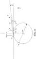
- Figure 4further illustrates the relative position between the trimming device 14 and the side edges 23a-d or the round corners 24a-d of the card 2 when the blade 44 trims the respective side edges or round corners.
- the guide surface 44g of the blade 44is tangent with respect to the circle 35 that has the radius of R and the center C at the intersection of the shaft axis 32a and the XY plane. In this way, the guide surface 44g is aligned parallel to and contacts the side edges 23a-d of the card 2 when the trimming device 14 trims the respective side edges, as shown in Figs.
- the blade edge 44eis advanced with respect to the point of tangency 44t, and the guide surface 44g is tangent with respect to the surface of the round corners 24a-d of the card 2 when the trimming device 14 trims the respective round corners, as shown in Figs. 3a-c .
- the trimming device 14can move along the Z axis and move along the X or Y axes to press the guide surface 44g of the blade 44 against one of the side edges, e.g., edge 23d, of the card 2. Then the trimming device 14 can move from a "start" point linearly along the X axis or the side edge 23d to have the blade edge 44e to trim the side edge 23d. At the corner 24d, the trimming device 14 can rotate about 90° around the shaft axis 32a to have the blade edge 44e to trim the corner 24d. Then the trimming device 14 can move linearly along the Y axis or the side edge 23a to have the blade edge 44e to trim the side edge 23a.
- the trimming device 14can rotate about 90° around the shaft axis 32a to have the blade edge 44e to trim the corner 24a. Then the trimming device 14 can move linearly along the -X axis or the side edge 23b to have the blade edge 44e to trim the side edge 23b. At the corner 24b, the trimming device 14 can rotate about 90° around the shaft axis 32a to have the blade edge 44e to trim the corner 24b. Then the trimming device 14 can move linearly along the -Y axis or the side edge 23c to have the blade edge 44e to trim the side edge 23c. At the corner 24c, the trimming device 14 can rotate about 90° around the shaft axis 32a to have the blade edge 44e to trim the corner 24c. Then the trimming device 14 can linearly along the X axis or the side edge 23d and trim the side edge 23d till back to the "start" point.
- the trimming device 14can trim a portion of the periphery of the card 2, for example, one or more of the side edges 23a-d along the X and/or Y axes.
- the trimming device 14can move along the edges of a card in a clockwise or counterclockwise direction in the XY plane. In some embodiments, one trimming device can be used to trim two or more edges of the card at the same time. In some embodiments, more than one trimming devices can be used.
- the blade 44can have a flexibility to bend, which allows to accommodate a positioning error of, for example, about 0.050"(about 1.3 mm), between the blade 44 and the side edge of the card 2.
- the blade 44can be pressed against the side edge of the card 2 and the blade edge 44e can be tilted with respect the Z axis to cut into the periphery of an overlay laminated on the top surface 21 to form a bevel feature into the overlay.
- This bevel featurecan make it difficult to remove the overlay from the card 2.
- the blade 44can be pressed against the side edge of the card 2 to remove overhanging parts of laminated overlays on both the top surface 21 and the bottom surface 22 at the same time.
- the removed overhanging parts of the overlaycan be collected and recycled.
- a trimming devicesuch as, for example, the trimming device 14, can be used to trim the card 2 itself to obtain a desired periphery of the card 2.
- a trimming devicesuch as, for example, the trimming device 14, can be used to divide a substrate into one or more personalized documents such as, for example, the card 2.
Landscapes
- Engineering & Computer Science (AREA)
- Mechanical Engineering (AREA)
- Life Sciences & Earth Sciences (AREA)
- Forests & Forestry (AREA)
- Credit Cards Or The Like (AREA)
- Laser Beam Processing (AREA)
- Grinding And Polishing Of Tertiary Curved Surfaces And Surfaces With Complex Shapes (AREA)
Description
- This disclosure relates to systems and methods of preparing personalized documents, such as plastic cards including, for example, identification cards, credit and debit cards, and the like. More particularly, this disclosure relates to utilizing a trimmer to process a personalized document.
- Personalized documents such as identification cards, credit and debit cards, driver's licenses, and the like, can have a regular shape such as, for example, a rectangular shape with curved corners. Some of the cards may have an overlay or overlay laminated on a substrate. The overlay needs to conform to the substrate.
U.S. Patent Number 5,785,355 discloses a method of producing single unit phone card assemblies having a primary sheet and an overlay, including the steps of cutting to create external dimensions of the assembly, and stripping excess material from the assembly. However, the document does not suggest to use a trimming device according to the present invention. - Systems and methods for utilizing a trimming system or a trimmer to process a personalized document, are provided. The personalized document includes, but is not limited to, identification cards, driver's licenses, credit and debit cards, and the like.
- In some embodiments, a personalized document such as, for example, a plastic card, includes a major surface laminated with an overlay. The laminated overlay may have a periphery that can overhang the edge of the personalized document. The embodiments described herein can trim, via a trimming device, an overhanging part of the laminated overlay by moving the trimming device along the edge of the personalized document in a direction generally parallel to the major surface of the personalized document. In some embodiments, the trimming device is a mechanical trimming device.
- In one embodiment, a method is provided where a trimming device is positioned with respect to a personalized document. The personalized document has a major surface and an edge being a periphery of the major surface. The edge of the personalized document is trimmed, via the trimming device, by moving the trimming device along the edge of the personalized document in a direction generally parallel to the major surface.
- In another embodiment, a method of trimming a round corner of a personalized document is provided. A trimming device is positioned with respect to the personalized document that has a major surface and an edge being a periphery of the major surface. The edge includes a round corner. The round corner of the personalized document is trimmed, via the trimming device, by rotating the trimming device around the round corner.
- In another embodiment, a system for preparing a personalized document is provided. The system includes a trimming unit configured to trim an edge of the personalized document. The trimming unit includes a trimming device, a mounting mechanism configured to mount the personalized document and positioning the personalized document with respect to the trimming device, and a manipulating mechanism configured to manipulate the trimming device and/or the personalized document so that the trimming device moves along the edge of the personalized document to trim the edge thereof.
- In another embodiment, a trimming system for trimming an edge of a personalized document is provided. The personalized document includes a major surface. The edge is a periphery of the major surface. The trimming system includes a trimming device, a mounting mechanism configured to mount the personalized document and positioning the personalized document with respect to the trimming device, and a manipulating mechanism configured to manipulate the trimming device and/or the personalized document so that the trimming device moves along the edge of the personalized document in a direction generally parallel to the major surface to trim the edge thereof.
- The term "trim" or "trimming" used herein refers to a process of defining a periphery (e.g., an edge, a corner) of a personalized document. The process of trimming can include, for example, removing an overhanging periphery of an overlay that is laminated on the personalized document, cutting a periphery of a personalized document, cutting a personalized document from a substrate, dividing a substrate into multiple personalized documents, etc.
- The term "edge" used herein refers to a periphery of a personalized document. It is to be appreciated that an edge includes a round corner.
- As used herein, "moving the trimming device along the edge of the personalized document" includes moving the trimming device and/or the personalized document.
Figure 1a illustrates a perspective front view of a system for preparing a personalized document, according to one embodiment.Figure 1b illustrates a perspective back view of the system ofFig. 1a .Figure 1c illustrates a top view of the system ofFig. 1a .Figure 1d illustrates a side view of the system ofFig. 1a along a d-d direction shown inFig. 1a .Figure 1e illustrates a back view of the system ofFig. 1a along an e-e direction shown inFig. 1b .Figure 2a illustrates a perspective view of a trimming device positioned with respect to a personalized document during trimming an edge of the personalized document, according to one embodiment.Figure 2b illustrates a top view of the trimming device and the personalized document ofFig. 2a .Figure 2c illustrates a partial enlarged view ofFig. 2b .Figure 3a illustrates a perspective view of the trimming device ofFig. 2a positioned with respect to the personalized document during trimming a round corner of the personalized document.Figure 3b illustrates a top view of the trimming device and the personalized document ofFig. 3a .Figure 3c illustrates a partial enlarged view ofFig. 3b .Figure 4 is a schematic diagram of positioning a trimming device with respect to a personalized document to trim an edge thereof, according to one embodiment.- Systems and methods for utilizing a trimmer to trim an edge of a personalized document, are provided. The personalized document includes, but is not limited to, identification cards, driver's licenses, credit and debit cards, and the like. The term "personalized" is intended to encompass documents that have personalization applied to them, as well as documents that do not have any applied personalization and that are to be personalized.
- The embodiments described herein can trim an overhanging part of an overlay laminated on a major surface of a personalized document such as, for example, a plastic card. The overlay can have a thickness, for example, from about 0.0005" to about 0.005" (0.013 mm to 0.13 mm) (or about 0.5 mil to about 5 mil). The embodiments described herein can trim an edge and/or a comer of a plastic card to cut into the periphery of the overlay to form a bevel feature, which can make it difficult to remove the overlay from the plastic card.
Figures 1a-e illustrate asystem 100 for preparing apersonalized document 2, according to one embodiment. In the embodiment ofFig. 1 , thepersonalized document 2 is a card having a generally rectangular shape. Thecard 2 can be made of plastic. An overlay was laminated on a top surface of thecard 2. In some embodiments, the overlay can be made of, for example, polyester, polycarbonate and/or photopolymer. The overlay can have a thickness above, for example, about 0.5 mil (about 0.013 mm). An overlay can also be laminated on a bottom surface of thecard 2 that is opposite the top surface. The overlay can have an overhanging part that overhangs an edge of thecard 2. The edge refers to the periphery of the top/bottom surface ofcard 2. Thesystem 100 includes atrimming unit 10 configured to trim the edge of thecard 2 and the overhanging part of the overlay from thecard 2 can be removed by trimming.- In some embodiments, the
system 100 can be a part of a desktop card printer for producing personalized documents. In some embodiments, thesystem 100 can be a part of a central card issuance system that can produce personalized documents. - The
system 100 can further include a laminating unit 20 (shown inFig. 1a only) positioned at an upstream position with respect to thetrimming unit 10. Thelaminating unit 20 is configured to laminate an overlay on a major surface of thecard 2. In some embodiments, the laminated overlay can have a periphery overhanging the edge of thecard 2. Then thecard 2 is transferred from thelaminating unit 20 to thetrimming unit 20 to remove the overhanging periphery. It is to be understood that thelaminating unit 20 and thetrimming unit 10 may not be directly connected and one or more processing units may be positioned therebetween. - The trimming
unit 10 can include a mountingmechanism 12 to mount thecard 2. The mountingmechanism 12 includes avacuum plate 122 having a top surface contacting a bottom surface of thecard 2. Themounted card 2 is positioned in a XY plane and faces in the direction of a Z axis. The working mechanism of a vacuum plate for mounting an object is known. The mountingmechanism 12 can rotate thecard 2 in the XY plane to align thecard 2 with respect to an X axis and a Y axis of the XY plane. In some embodiments, thecard 2 can be aligned with respective edges being parallel to the X axis and the Y axis, respectively. It is to be understood that mounting mechanisms other than a vacuum plate can be used. - The trimming
unit 10 further includes atrimming device 14 that is mounted on a manipulatingmechanism 16. The trimmingdevice 14 is manipulated by the manipulatingmechanism 16 and is capable of moving around the edge of thecard 2 in the XY plane to trim at least a portion of the edge thereof. One embodiment of thetrimming device 14 is illustrated inFig. 2a to be discussed further below. - The manipulating
mechanism 16 includes anX axis manipulator 164 for moving thetrimming device 14 along the X axis, aY axis manipulator 162 for moving thetrimming device 14 along the Y axis, aZ axis manipulator 166 for moving thetrimming device 14 along the Z axis, and a Zaxis rotation manipulator 168 for rotating thetrimming device 14 around the Z axis. TheX axis manipulator 164, theY axis manipulator 162, and theZ axis manipulator 166 each can include a lead screw that extends along the respective axis. The manipulatingmechanism 16 can also include one or more motors for providing a driving force for the X, Y andZ axis manipulators axis rotation manipulator 168. - The manipulating
mechanism 16 further includes a shaft 32 (shown inFig. 2a ) that extends along ashaft axis 32a thereof. Theshaft axis 32a of theshaft 32 is positioned generally parallel to the axis Z. Theshaft 32 is connected to theX axis manipulator 164, theY axis manipulator 162, theZ axis manipulator 166, and the Zaxis rotation manipulator 168. Theshaft 32 is manipulated by theX axis manipulator 164 to move linearly along the X axis, by theY axis manipulator 162 to move linearly along the Y axis, by theZ axis manipulator 166 to move linearly along the Z axis, and by the Zaxis rotation manipulator 168 to rotate around theshaft axis 32a. The trimmingdevice 14 is mounted to theshaft 32 via aholder block 34. - The trimming
unit 10 can further include an optionalvision location mechanism 18 for locating the edge and/or corner of thecard 2. Thevision location mechanism 18 includes avision device 182 facing thecard 2. Thevision device 182 is mounted on the manipulatingmechanism 16 and manipulated by the manipulatingmechanism 16 to move along the X axis, the Y axis, and/or the Z axis, and/or rotate around the Z axis. Thevision device 182 can be, for example, a camera that has a resolution of a dimension of about 0.001" (about 0.0254 mm) or better. Optionally, thevision location mechanism 18 can include a lighting device to illuminate thecard 2, for example, from below. The lighting device can be, for example, a light-emitting diode (LED). - In some embodiments, the
system 100 can include a microprocessor (e.g., a Central Processing Unit or CPU, not shown) for controlling the trimmingunit 10 where thevision location mechanism 18 can be coupled to the microprocessor. - The trimming
unit 10 further includes a base 11 where components of the trimming unit 10 (e.g., the mountingmechanism 12, the trimmingdevice 14, the manipulatingmechanism 16, thevision location mechanism 18, etc.) are mounted thereon. - In some embodiments, the
vision device 182 can be moved, via the manipulatingmechanism 16, from a home position to preset locations to optically locate the edges and/or corners of thecard 2 with respect the X and Y axes. Then the trimmingdevice 14 can be moved, by the manipulatingmechanism 16, along the Z axis a preset distance to a "start" position. Then the trimmingdevice 14 can move along the edge of thecard 2 in a direction generally parallel to the XY plane to trim the edges and/or corners of thecard 2. - In the embodiments of
Figs. 2a-c and3a-c , thecard 2 to be trimmed by the trimmingdevice 14 has a generally rectangular shape including, for example, fourside edges 23a-d and fourround corners 24a-d at respective junctions of the side edges. Thecard 2 has a firstmajor surface 21 and a secondmajor surface 22 opposite the firstmajor surface 21. It is to be understood that thecard 2 can have other suitable shapes. - The
card 2 and theshaft 32 are positioned with respect to each other so that theshaft axis 32a of theshaft 32 is positioned generally perpendicular to themajor surfaces card 2.Figures 2a-c illustrate thetrimming device 14 positioned with respect to thecard 2 to trim one of the side edges, e.g.,edge 23d, according to one embodiment. - In the embodiments described herein, the trimming
device 14 is a mechanical trimming device. It is to be understood that thetrimming device 14 can be other types of trimming devices such as, for example, optical trimming devices, electrical trimming devices, thermal trimming devices, etc., that are suitable to trim the edges and/or corners of a personalized document. - In some embodiments, the trimming
device 14 can include a laser (not shown) that is configured to trim at least a portion of the periphery of thecard 2. The laser can emit a light beam in a direction generally perpendicular to the top/bottom surface ofcard 2. The laser can be manipulated by, e.g., the manipulatingmechanism 16, to move around the edge of thecard 2 in the XY plane to trim the edge. - The trimming
device 14 shown inFigs. 2a-c and3a-c includes ablade 44 having ablade body 42 mounted on theholder block 34. Theblade body 42 extends along the Z axis and beyond anend 34a of theholder block 34. - As shown in
Fig. 2c , theholder block 34 defines a mounting surface 34f and theblade body 42 defines aside surface 42f. Theblade 44 is mounted to theholder block 34 with theside surface 42f contacting the mounting surface 34f. During a trimming process, theholder block 34 is positioned with respect to thecard 2 so that the mounting surface 34f forms an angle α with respect to theside edge 23d of thecard 2. The angle α can be, for example, about 11°. - As shown in
Figs. 2a ,2c ,3c and4 , theblade body 42 further defines a guide surface 44g and ablade edge 44e defined at an end of the guide surface 44g. The guide surface 44g is angled with respect to the mounting surface 34f and theside surface 42f. - During a trimming process, the
blade 44 is pressed against the side edge of thecard 2 and the guide surface 44g is aligned generally parallel to the side edge, e.g., 23d of thecard 2. - The
blade edge 44e can trim theside edge 23d when theshaft 32 moves linearly along aline 33d generally parallel to theside edge 23d. Theshaft 32 is positioned with respect to thecard 2 with theshaft axis 32a being offset with respect to the side edge of thecard 2. For example, the distance between theline 33d and theside edge 23d isd. - As shown in
Figs. 2c ,3c and4 , in the XY plane, the guide surface 44g is tangent with respect to acircle 35 that has the radius ofd and the center C at the intersection of theshaft axis 32a and theline 33d. The point of tangency is 44t. Theblade edge 44e is positioned at an advanced position with respect to the point of tangency 44t. The distance between the point of tangency 44t and theblade edge 44e ist. The distancet can have a range of, for example, about 0.005" to about 0.025" (about 0.13 mm to 0.064 mm). - As shown in
Figs. 3a ,3b or3c , when theshaft 32 moves along aline 33a to a round corner, e.g.,corner 24a of thecard 2, theshaft 32 rotates about 90° around theshaft axis 32a and theblade 44 trims the respectiveround corner 24a. Then theshaft 32 continues to move along a line 33b to trim the side edge 23b. During the trimming, theshaft axis 32a of theshaft 32 is offset with respect to the side edges, e.g., 23a and 23b, of thecard 2. The distanced between theline 33a and theside edge 23a, or the distanced between the line 33b and the side edge 23b, is substantially equal to the radiusR of theround corner 24a that can be, for example, about 0.125" (about 3.2 mm). In this way, theblade edge 44e can be advanced with respect to the point of tangency 44t, and the guide surface 44g of theblade 44 can be always tangent with respect to the surface of the round corner, e.g., 24a when theblade edge 44e trims the respective round corner of thecard 2. Figure 4 further illustrates the relative position between the trimmingdevice 14 and the side edges 23a-d or theround corners 24a-d of thecard 2 when theblade 44 trims the respective side edges or round corners. The guide surface 44g of theblade 44 is tangent with respect to thecircle 35 that has the radius of R and the center C at the intersection of theshaft axis 32a and the XY plane. In this way, the guide surface 44g is aligned parallel to and contacts the side edges 23a-d of thecard 2 when thetrimming device 14 trims the respective side edges, as shown inFigs. 2a-c , theblade edge 44e is advanced with respect to the point of tangency 44t, and the guide surface 44g is tangent with respect to the surface of theround corners 24a-d of thecard 2 when thetrimming device 14 trims the respective round corners, as shown inFigs. 3a-c .- In some embodiments, the trimming
device 14 can move along the Z axis and move along the X or Y axes to press the guide surface 44g of theblade 44 against one of the side edges, e.g.,edge 23d, of thecard 2. Then the trimmingdevice 14 can move from a "start" point linearly along the X axis or theside edge 23d to have theblade edge 44e to trim theside edge 23d. At thecorner 24d, the trimmingdevice 14 can rotate about 90° around theshaft axis 32a to have theblade edge 44e to trim thecorner 24d. Then the trimmingdevice 14 can move linearly along the Y axis or theside edge 23a to have theblade edge 44e to trim theside edge 23a. At thecorner 24a, the trimmingdevice 14 can rotate about 90° around theshaft axis 32a to have theblade edge 44e to trim thecorner 24a. Then the trimmingdevice 14 can move linearly along the -X axis or the side edge 23b to have theblade edge 44e to trim the side edge 23b. At thecorner 24b, the trimmingdevice 14 can rotate about 90° around theshaft axis 32a to have theblade edge 44e to trim thecorner 24b. Then the trimmingdevice 14 can move linearly along the -Y axis or theside edge 23c to have theblade edge 44e to trim theside edge 23c. At thecorner 24c, the trimmingdevice 14 can rotate about 90° around theshaft axis 32a to have theblade edge 44e to trim thecorner 24c. Then the trimmingdevice 14 can linearly along the X axis or theside edge 23d and trim theside edge 23d till back to the "start" point. - In some embodiments, the trimming
device 14 can trim a portion of the periphery of thecard 2, for example, one or more of the side edges 23a-d along the X and/or Y axes. - In some embodiments, the trimming
device 14 can move along the edges of a card in a clockwise or counterclockwise direction in the XY plane. In some embodiments, one trimming device can be used to trim two or more edges of the card at the same time. In some embodiments, more than one trimming devices can be used. - In some embodiments, the
blade 44 can have a flexibility to bend, which allows to accommodate a positioning error of, for example, about 0.050"(about 1.3 mm), between theblade 44 and the side edge of thecard 2. - In some embodiments, the
blade 44 can be pressed against the side edge of thecard 2 and theblade edge 44e can be tilted with respect the Z axis to cut into the periphery of an overlay laminated on thetop surface 21 to form a bevel feature into the overlay. This bevel feature can make it difficult to remove the overlay from thecard 2. - In some embodiments, the
blade 44 can be pressed against the side edge of thecard 2 to remove overhanging parts of laminated overlays on both thetop surface 21 and thebottom surface 22 at the same time. - In some embodiments, the removed overhanging parts of the overlay can be collected and recycled.
- In some embodiments, a trimming device such as, for example, the trimming
device 14, can be used to trim thecard 2 itself to obtain a desired periphery of thecard 2. - In some embodiments, a trimming device such as, for example, the trimming
device 14, can be used to divide a substrate into one or more personalized documents such as, for example, thecard 2.
Claims (15)
- A method of trimming at least a portion of an edge (23a-d) of a personalized document (2) comprising:positioning a trimming device (14) with respect to a personalized document (2) that has a major surface (21, 22) and an edge (23a-d) being a periphery of the major surface, where the trimming device is a mechanical trimming device that includes a holder block (34) and a blade (44) mounted to the holder block and a laser configured to emit a laser beam in a direction generally perpendicular to the XY plane, the blade includes a blade body (42) that defines a side surface (42f) and a guide surface (44g), a blade edge (44e) is defined at one end of the guide surface, and the guide surface is positioned parallel to the edge of the personalized document when the blade edge trims the edge of the personalized document; andtrimming, via the trimming device, at least a portion of the edge of the personalized document by moving the trimming device along the edge of the personalized document in a direction generally parallel to the major surface.
- The method of claim 1, wherein trimming the edge of the personalized document includes removing a periphery of an overlay that has been laminated on the major surface of the personalized document, the periphery of the overlay overhanging the edge of the personalized document.
- The method of claim 1, wherein moving the trimming device includes linearly moving the trimming device along an X axis or a Y axis that are orthogonal to each other, and rotating the trimming device around a rotating axis (32a) that is generally parallel to a Z axis orthogonal to the X and Y axes.
- The method of claim 1, further comprising aligning the guide surface of the blade parallel to the edge of the personalized document and pressing the guide surface against the edge of the personalized document.
- The method of claim 1, further comprising rotating the blade edge around a rotating shaft (32) that is generally perpendicular to the major surface of the personalized document to trim a round corner (24a-d) of the personalized document.
- The method of claim 5, wherein the rotating shaft is positioned with an offset (d) with respect to the edge of the personalized document, and the blade edge is positioned at an advanced position ahead of a point of tangency (44t) of the guide surface with respect to the round corner when rotating the blade edge.
- A trimming system for trimming an edge (23a-d) of a personalized document (2), the personalized document including a major surface (21, 22), the edge being a periphery of the personalized document, the trimming system comprising:a trimming device (14), the trimming device is one of a mechanical trimming device that includes a holder block (34) and a blade (44) mounted to the holder block and a laser configured to emit a laser beam in a direction generally perpendicular to the XY plane,characterized in that the blade includes a blade body (42) that defines a side surface (42f) and a guide surface (44g), a blade edge (44e) is defined at one end of the guide surface, and the guide surface is positioned parallel to the edge of the personalized document when the blade edge trims the edge of the personalized document;and wherein the trimming system further comprises:a mounting mechanism (12) configured to mount the personalized document and positioning the personalized document with respect to the trimming device; anda manipulating mechanism (16) configured to manipulate the trimming device and/or the personalized document so that the trimming device moves along the edge of the personalized document in a direction generally parallel to the major surface to trim at least a portion of the edge thereof.
- The trimming system of claim 7, wherein the trimming system further includes a vision device (182) configured to locate the edge of the personalized document.
- The trimming system of claim 7, wherein the holder block includes a mounting surface (34f) contacting the side surface of the blade body, the mounting surface and the side surface are angled with respect to the edge of the personalized document.
- The trimming system of claim 7, wherein the blade edge is positioned at an advanced position ahead of a tangent point (44t) of the guide surface with the edge of the personalized document.
- The trimming system of claim 7, wherein the manipulating mechanism includes a shaft (32) positioned generally perpendicular to the major surface of the personalized document, the blade is mounted on the shaft, and the shaft is positioned with an offset (d) with respect to the edge of the personalized document.
- The trimming system of claim 11, wherein the shaft is linearly movable along an X axis and a Y axis orthogonal to each other, and the shaft is rotatable around a rotating axis (32a) that is generally parallel to a Z axis orthogonal to the X and Y axes.
- The trimming system of claim 11, wherein the offset is the radius of a round corner (24a-d) of the personalized document.
- A system (100) for preparing a personalized document (2) including the trimming system of any one of claims 7-13.
- The system of claim 14, further comprising a laminating unit (20) positioned upstream of the trimming unit and configured to laminate an overlay on a major surface of the personalized document, wherein the laminated overlay has a periphery overhanging the edge of the personalized document, and the trimming device is configured to remove the overhanging periphery of the laminated overlay.
Applications Claiming Priority (2)
| Application Number | Priority Date | Filing Date | Title |
|---|---|---|---|
| US201361822481P | 2013-05-13 | 2013-05-13 | |
| PCT/US2014/032361WO2014186063A1 (en) | 2013-05-13 | 2014-03-31 | Card overlay trimmer |
Publications (3)
| Publication Number | Publication Date |
|---|---|
| EP2996846A1 EP2996846A1 (en) | 2016-03-23 |
| EP2996846A4 EP2996846A4 (en) | 2017-01-04 |
| EP2996846B1true EP2996846B1 (en) | 2020-10-28 |
Family
ID=51863938
Family Applications (1)
| Application Number | Title | Priority Date | Filing Date |
|---|---|---|---|
| EP14798279.7AActiveEP2996846B1 (en) | 2013-05-13 | 2014-03-31 | Card overlay trimmer |
Country Status (4)
| Country | Link |
|---|---|
| US (1) | US9452542B2 (en) |
| EP (1) | EP2996846B1 (en) |
| CN (1) | CN105492174B (en) |
| WO (1) | WO2014186063A1 (en) |
Families Citing this family (1)
| Publication number | Priority date | Publication date | Assignee | Title |
|---|---|---|---|---|
| JP6938033B2 (en)* | 2016-05-27 | 2021-09-22 | 株式会社ラミーコーポレーション | Laminating equipment |
Family Cites Families (14)
| Publication number | Priority date | Publication date | Assignee | Title |
|---|---|---|---|---|
| SE415347B (en) | 1978-12-07 | 1980-09-29 | Tetra Pak Int | DEVICE FOR EDGE CUTTING OF A CURRENT LAMINATE COAT |
| EP0246740B1 (en)* | 1986-04-04 | 1991-07-31 | Eliot M. Glick | Process and apparatus for making a postcard |
| CH671161A5 (en)* | 1987-06-29 | 1989-08-15 | Swylon S A | |
| US5163008A (en)* | 1990-08-21 | 1992-11-10 | Gerber Garment Technology, Inc. | Method and apparatus for advancing sheet material for the cutting of successive segments thereof |
| DE4130269C2 (en)* | 1990-09-13 | 1996-05-23 | Toshiba Machine Co Ltd | Method and device for manufacturing laminated prepreg parts |
| US5785355A (en)* | 1996-11-19 | 1998-07-28 | Kobel, Inc. | Single unit phone card assembly and method of producing same |
| JP3317644B2 (en)* | 1996-11-29 | 2002-08-26 | セントラル硝子株式会社 | Method and apparatus for cutting edge of interlayer film sandwiched between glass sheets |
| IT1291159B1 (en)* | 1997-02-28 | 1998-12-29 | Bottero Spa | CUTTING GROUP FOR TRIMMING AT LEAST ONE FLEXIBLE SHEET PLACED AT LEAST ONE SHEET. |
| US6536497B2 (en)* | 2001-04-18 | 2003-03-25 | Banner American Products, Inc. | Laminating system |
| KR100522851B1 (en)* | 2003-06-30 | 2005-10-19 | 주식회사 케이디엔스마텍 | Method for manufacturing plastic cards using silicone-denatured waterborne polyurethane resin adhesive containing amethyst powders |
| US20050134036A1 (en) | 2003-12-22 | 2005-06-23 | Trimble Michael A. | Method and apparatus for manufacturing a laminated identification card |
| US7028909B2 (en)* | 2004-08-13 | 2006-04-18 | Ge Identicard Systems, Inc. | Laminate tabbed pouch identification card with an integrated circuit |
| JP2006116682A (en)* | 2004-10-25 | 2006-05-11 | Carl Manufacturing Co Ltd | Cutter head |
| EP2174784A1 (en)* | 2008-10-13 | 2010-04-14 | 3S Swiss Solar Systems AG | Procedure to remove a projecting section of a laminate layer |
- 2014
- 2014-03-31EPEP14798279.7Apatent/EP2996846B1/enactiveActive
- 2014-03-31WOPCT/US2014/032361patent/WO2014186063A1/enactiveApplication Filing
- 2014-03-31USUS14/230,503patent/US9452542B2/enactiveActive
- 2014-03-31CNCN201480035339.3Apatent/CN105492174B/enactiveActive
Non-Patent Citations (1)
| Title |
|---|
| None* |
Also Published As
| Publication number | Publication date |
|---|---|
| EP2996846A4 (en) | 2017-01-04 |
| US9452542B2 (en) | 2016-09-27 |
| US20140332152A1 (en) | 2014-11-13 |
| EP2996846A1 (en) | 2016-03-23 |
| WO2014186063A1 (en) | 2014-11-20 |
| CN105492174A (en) | 2016-04-13 |
| CN105492174B (en) | 2017-12-26 |
Similar Documents
| Publication | Publication Date | Title |
|---|---|---|
| TWI673521B (en) | Processing device | |
| EP2488333B1 (en) | An apparatus for cutting articles comprising a flat surface on which designs and/or writings are reproduced and a method for actuating the apparatus | |
| US20110119898A1 (en) | Method for machining a laminate | |
| US11247304B2 (en) | Workpiece information recognition system | |
| EP2996846B1 (en) | Card overlay trimmer | |
| KR20170108888A (en) | Laminated sheet polishing method and apparatus performing the same | |
| KR101493597B1 (en) | Tip holder storage body | |
| KR101494525B1 (en) | Tip holder storage body | |
| US5694853A (en) | Alignment method for accurately registering sheet material on a plate and fixture therefor | |
| JP5781381B2 (en) | fixing jig | |
| EP2687325A1 (en) | Lathe control system | |
| CN104669333B (en) | For processing the apparatus and method at the edge of light guide plate | |
| CN102950625A (en) | Resin cutter die with adjustable pitch | |
| CN118431104A (en) | Table control method and device and wafer slotting equipment | |
| EP3059649B1 (en) | A method for positioning a glass sheet on a working plane of a glass sheet working machine | |
| CN111873070B (en) | Film cutting device and film cutting method | |
| CN112296209B (en) | Bending and pin shearing device | |
| KR20060102241A (en) | Brittle material sorting device and sorting method | |
| JPH05259340A (en) | Method and apparatus for cutting lead frame for ic package of various dimensions | |
| JP2002050820A (en) | Method and device for cleaving semiconductor device | |
| KR102629811B1 (en) | Guide device for manufacturing printed circuit board in which both surfacs are processed under same condition by the rotation movement of the clamping jig member | |
| CN216884364U (en) | Die cutting device and die cutting equipment | |
| CN206998399U (en) | Feed arrangement | |
| CN218314459U (en) | Cutting device | |
| WO2017196638A2 (en) | Alignment system and method of using the same |
Legal Events
| Date | Code | Title | Description |
|---|---|---|---|
| PUAI | Public reference made under article 153(3) epc to a published international application that has entered the european phase | Free format text:ORIGINAL CODE: 0009012 | |
| 17P | Request for examination filed | Effective date:20151211 | |
| AK | Designated contracting states | Kind code of ref document:A1 Designated state(s):AL AT BE BG CH CY CZ DE DK EE ES FI FR GB GR HR HU IE IS IT LI LT LU LV MC MK MT NL NO PL PT RO RS SE SI SK SM TR | |
| AX | Request for extension of the european patent | Extension state:BA ME | |
| DAX | Request for extension of the european patent (deleted) | ||
| A4 | Supplementary search report drawn up and despatched | Effective date:20161205 | |
| RIC1 | Information provided on ipc code assigned before grant | Ipc:B26D 5/00 20060101ALI20161129BHEP Ipc:B26D 1/04 20060101ALI20161129BHEP Ipc:B26D 1/58 20060101AFI20161129BHEP Ipc:B26F 1/38 20060101ALI20161129BHEP Ipc:B23K 26/00 20140101ALI20161129BHEP Ipc:B26D 5/34 20060101ALI20161129BHEP Ipc:B26D 7/01 20060101ALI20161129BHEP Ipc:B42D 25/00 20140101ALI20161129BHEP Ipc:B26D 7/00 20060101ALI20161129BHEP Ipc:B32B 37/00 20060101ALI20161129BHEP | |
| RIC1 | Information provided on ipc code assigned before grant | Ipc:B26D 5/34 20060101ALI20200325BHEP Ipc:B23K 26/00 20140101ALI20200325BHEP Ipc:B26D 7/00 20060101ALI20200325BHEP Ipc:B26F 1/38 20060101ALI20200325BHEP Ipc:B26D 7/01 20060101ALI20200325BHEP Ipc:B32B 38/00 20060101ALI20200325BHEP Ipc:B26D 1/58 20060101AFI20200325BHEP Ipc:B42D 25/00 20140101ALI20200325BHEP Ipc:B32B 37/00 20060101ALI20200325BHEP Ipc:B26D 1/04 20060101ALI20200325BHEP Ipc:B26D 5/00 20060101ALI20200325BHEP | |
| GRAP | Despatch of communication of intention to grant a patent | Free format text:ORIGINAL CODE: EPIDOSNIGR1 | |
| STAA | Information on the status of an ep patent application or granted ep patent | Free format text:STATUS: GRANT OF PATENT IS INTENDED | |
| INTG | Intention to grant announced | Effective date:20200512 | |
| GRAS | Grant fee paid | Free format text:ORIGINAL CODE: EPIDOSNIGR3 | |
| GRAA | (expected) grant | Free format text:ORIGINAL CODE: 0009210 | |
| STAA | Information on the status of an ep patent application or granted ep patent | Free format text:STATUS: THE PATENT HAS BEEN GRANTED | |
| AK | Designated contracting states | Kind code of ref document:B1 Designated state(s):AL AT BE BG CH CY CZ DE DK EE ES FI FR GB GR HR HU IE IS IT LI LT LU LV MC MK MT NL NO PL PT RO RS SE SI SK SM TR | |
| REG | Reference to a national code | Ref country code:GB Ref legal event code:FG4D | |
| REG | Reference to a national code | Ref country code:CH Ref legal event code:EP | |
| REG | Reference to a national code | Ref country code:AT Ref legal event code:REF Ref document number:1327750 Country of ref document:AT Kind code of ref document:T Effective date:20201115 | |
| REG | Reference to a national code | Ref country code:DE Ref legal event code:R096 Ref document number:602014071757 Country of ref document:DE | |
| REG | Reference to a national code | Ref country code:IE Ref legal event code:FG4D | |
| REG | Reference to a national code | Ref country code:NL Ref legal event code:FP | |
| REG | Reference to a national code | Ref country code:AT Ref legal event code:MK05 Ref document number:1327750 Country of ref document:AT Kind code of ref document:T Effective date:20201028 | |
| PG25 | Lapsed in a contracting state [announced via postgrant information from national office to epo] | Ref country code:GR Free format text:LAPSE BECAUSE OF FAILURE TO SUBMIT A TRANSLATION OF THE DESCRIPTION OR TO PAY THE FEE WITHIN THE PRESCRIBED TIME-LIMIT Effective date:20210129 Ref country code:FI Free format text:LAPSE BECAUSE OF FAILURE TO SUBMIT A TRANSLATION OF THE DESCRIPTION OR TO PAY THE FEE WITHIN THE PRESCRIBED TIME-LIMIT Effective date:20201028 Ref country code:RS Free format text:LAPSE BECAUSE OF FAILURE TO SUBMIT A TRANSLATION OF THE DESCRIPTION OR TO PAY THE FEE WITHIN THE PRESCRIBED TIME-LIMIT Effective date:20201028 Ref country code:NO Free format text:LAPSE BECAUSE OF FAILURE TO SUBMIT A TRANSLATION OF THE DESCRIPTION OR TO PAY THE FEE WITHIN THE PRESCRIBED TIME-LIMIT Effective date:20210128 Ref country code:PT Free format text:LAPSE BECAUSE OF FAILURE TO SUBMIT A TRANSLATION OF THE DESCRIPTION OR TO PAY THE FEE WITHIN THE PRESCRIBED TIME-LIMIT Effective date:20210301 | |
| REG | Reference to a national code | Ref country code:LT Ref legal event code:MG4D | |
| PG25 | Lapsed in a contracting state [announced via postgrant information from national office to epo] | Ref country code:ES Free format text:LAPSE BECAUSE OF FAILURE TO SUBMIT A TRANSLATION OF THE DESCRIPTION OR TO PAY THE FEE WITHIN THE PRESCRIBED TIME-LIMIT Effective date:20201028 Ref country code:AT Free format text:LAPSE BECAUSE OF FAILURE TO SUBMIT A TRANSLATION OF THE DESCRIPTION OR TO PAY THE FEE WITHIN THE PRESCRIBED TIME-LIMIT Effective date:20201028 Ref country code:BG Free format text:LAPSE BECAUSE OF FAILURE TO SUBMIT A TRANSLATION OF THE DESCRIPTION OR TO PAY THE FEE WITHIN THE PRESCRIBED TIME-LIMIT Effective date:20210128 Ref country code:PL Free format text:LAPSE BECAUSE OF FAILURE TO SUBMIT A TRANSLATION OF THE DESCRIPTION OR TO PAY THE FEE WITHIN THE PRESCRIBED TIME-LIMIT Effective date:20201028 Ref country code:IS Free format text:LAPSE BECAUSE OF FAILURE TO SUBMIT A TRANSLATION OF THE DESCRIPTION OR TO PAY THE FEE WITHIN THE PRESCRIBED TIME-LIMIT Effective date:20210228 Ref country code:LV Free format text:LAPSE BECAUSE OF FAILURE TO SUBMIT A TRANSLATION OF THE DESCRIPTION OR TO PAY THE FEE WITHIN THE PRESCRIBED TIME-LIMIT Effective date:20201028 Ref country code:SE Free format text:LAPSE BECAUSE OF FAILURE TO SUBMIT A TRANSLATION OF THE DESCRIPTION OR TO PAY THE FEE WITHIN THE PRESCRIBED TIME-LIMIT Effective date:20201028 | |
| PG25 | Lapsed in a contracting state [announced via postgrant information from national office to epo] | Ref country code:HR Free format text:LAPSE BECAUSE OF FAILURE TO SUBMIT A TRANSLATION OF THE DESCRIPTION OR TO PAY THE FEE WITHIN THE PRESCRIBED TIME-LIMIT Effective date:20201028 | |
| REG | Reference to a national code | Ref country code:DE Ref legal event code:R097 Ref document number:602014071757 Country of ref document:DE | |
| PG25 | Lapsed in a contracting state [announced via postgrant information from national office to epo] | Ref country code:EE Free format text:LAPSE BECAUSE OF FAILURE TO SUBMIT A TRANSLATION OF THE DESCRIPTION OR TO PAY THE FEE WITHIN THE PRESCRIBED TIME-LIMIT Effective date:20201028 Ref country code:CZ Free format text:LAPSE BECAUSE OF FAILURE TO SUBMIT A TRANSLATION OF THE DESCRIPTION OR TO PAY THE FEE WITHIN THE PRESCRIBED TIME-LIMIT Effective date:20201028 Ref country code:SM Free format text:LAPSE BECAUSE OF FAILURE TO SUBMIT A TRANSLATION OF THE DESCRIPTION OR TO PAY THE FEE WITHIN THE PRESCRIBED TIME-LIMIT Effective date:20201028 Ref country code:LT Free format text:LAPSE BECAUSE OF FAILURE TO SUBMIT A TRANSLATION OF THE DESCRIPTION OR TO PAY THE FEE WITHIN THE PRESCRIBED TIME-LIMIT Effective date:20201028 Ref country code:RO Free format text:LAPSE BECAUSE OF FAILURE TO SUBMIT A TRANSLATION OF THE DESCRIPTION OR TO PAY THE FEE WITHIN THE PRESCRIBED TIME-LIMIT Effective date:20201028 Ref country code:SK Free format text:LAPSE BECAUSE OF FAILURE TO SUBMIT A TRANSLATION OF THE DESCRIPTION OR TO PAY THE FEE WITHIN THE PRESCRIBED TIME-LIMIT Effective date:20201028 | |
| PG25 | Lapsed in a contracting state [announced via postgrant information from national office to epo] | Ref country code:DK Free format text:LAPSE BECAUSE OF FAILURE TO SUBMIT A TRANSLATION OF THE DESCRIPTION OR TO PAY THE FEE WITHIN THE PRESCRIBED TIME-LIMIT Effective date:20201028 | |
| PLBE | No opposition filed within time limit | Free format text:ORIGINAL CODE: 0009261 | |
| STAA | Information on the status of an ep patent application or granted ep patent | Free format text:STATUS: NO OPPOSITION FILED WITHIN TIME LIMIT | |
| 26N | No opposition filed | Effective date:20210729 | |
| PG25 | Lapsed in a contracting state [announced via postgrant information from national office to epo] | Ref country code:AL Free format text:LAPSE BECAUSE OF FAILURE TO SUBMIT A TRANSLATION OF THE DESCRIPTION OR TO PAY THE FEE WITHIN THE PRESCRIBED TIME-LIMIT Effective date:20201028 Ref country code:MC Free format text:LAPSE BECAUSE OF FAILURE TO SUBMIT A TRANSLATION OF THE DESCRIPTION OR TO PAY THE FEE WITHIN THE PRESCRIBED TIME-LIMIT Effective date:20201028 | |
| REG | Reference to a national code | Ref country code:CH Ref legal event code:PL | |
| PG25 | Lapsed in a contracting state [announced via postgrant information from national office to epo] | Ref country code:SI Free format text:LAPSE BECAUSE OF FAILURE TO SUBMIT A TRANSLATION OF THE DESCRIPTION OR TO PAY THE FEE WITHIN THE PRESCRIBED TIME-LIMIT Effective date:20201028 | |
| REG | Reference to a national code | Ref country code:BE Ref legal event code:MM Effective date:20210331 | |
| PG25 | Lapsed in a contracting state [announced via postgrant information from national office to epo] | Ref country code:LI Free format text:LAPSE BECAUSE OF NON-PAYMENT OF DUE FEES Effective date:20210331 Ref country code:LU Free format text:LAPSE BECAUSE OF NON-PAYMENT OF DUE FEES Effective date:20210331 Ref country code:CH Free format text:LAPSE BECAUSE OF NON-PAYMENT OF DUE FEES Effective date:20210331 Ref country code:IE Free format text:LAPSE BECAUSE OF NON-PAYMENT OF DUE FEES Effective date:20210331 | |
| PG25 | Lapsed in a contracting state [announced via postgrant information from national office to epo] | Ref country code:IS Free format text:LAPSE BECAUSE OF FAILURE TO SUBMIT A TRANSLATION OF THE DESCRIPTION OR TO PAY THE FEE WITHIN THE PRESCRIBED TIME-LIMIT Effective date:20210228 | |
| PG25 | Lapsed in a contracting state [announced via postgrant information from national office to epo] | Ref country code:BE Free format text:LAPSE BECAUSE OF NON-PAYMENT OF DUE FEES Effective date:20210331 | |
| PG25 | Lapsed in a contracting state [announced via postgrant information from national office to epo] | Ref country code:HU Free format text:LAPSE BECAUSE OF FAILURE TO SUBMIT A TRANSLATION OF THE DESCRIPTION OR TO PAY THE FEE WITHIN THE PRESCRIBED TIME-LIMIT; INVALID AB INITIO Effective date:20140331 | |
| PGFP | Annual fee paid to national office [announced via postgrant information from national office to epo] | Ref country code:DE Payment date:20230329 Year of fee payment:10 | |
| P01 | Opt-out of the competence of the unified patent court (upc) registered | Effective date:20230513 | |
| PG25 | Lapsed in a contracting state [announced via postgrant information from national office to epo] | Ref country code:CY Free format text:LAPSE BECAUSE OF FAILURE TO SUBMIT A TRANSLATION OF THE DESCRIPTION OR TO PAY THE FEE WITHIN THE PRESCRIBED TIME-LIMIT Effective date:20201028 | |
| PG25 | Lapsed in a contracting state [announced via postgrant information from national office to epo] | Ref country code:MK Free format text:LAPSE BECAUSE OF FAILURE TO SUBMIT A TRANSLATION OF THE DESCRIPTION OR TO PAY THE FEE WITHIN THE PRESCRIBED TIME-LIMIT Effective date:20201028 | |
| PGFP | Annual fee paid to national office [announced via postgrant information from national office to epo] | Ref country code:NL Payment date:20240426 Year of fee payment:11 | |
| PGFP | Annual fee paid to national office [announced via postgrant information from national office to epo] | Ref country code:GB Payment date:20240429 Year of fee payment:11 | |
| PGFP | Annual fee paid to national office [announced via postgrant information from national office to epo] | Ref country code:IT Payment date:20240422 Year of fee payment:11 Ref country code:FR Payment date:20240425 Year of fee payment:11 | |
| PG25 | Lapsed in a contracting state [announced via postgrant information from national office to epo] | Ref country code:MT Free format text:LAPSE BECAUSE OF FAILURE TO SUBMIT A TRANSLATION OF THE DESCRIPTION OR TO PAY THE FEE WITHIN THE PRESCRIBED TIME-LIMIT Effective date:20201028 |