EP2996556B1 - System for image guided procedure - Google Patents
System for image guided procedureDownload PDFInfo
- Publication number
- EP2996556B1 EP2996556B1EP14707828.1AEP14707828AEP2996556B1EP 2996556 B1EP2996556 B1EP 2996556B1EP 14707828 AEP14707828 AEP 14707828AEP 2996556 B1EP2996556 B1EP 2996556B1
- Authority
- EP
- European Patent Office
- Prior art keywords
- display
- tissue
- impedance
- electrode
- needle
- Prior art date
- Legal status (The legal status is an assumption and is not a legal conclusion. Google has not performed a legal analysis and makes no representation as to the accuracy of the status listed.)
- Active
Links
Images


Classifications
- A—HUMAN NECESSITIES
- A61—MEDICAL OR VETERINARY SCIENCE; HYGIENE
- A61B—DIAGNOSIS; SURGERY; IDENTIFICATION
- A61B8/00—Diagnosis using ultrasonic, sonic or infrasonic waves
- A61B8/08—Clinical applications
- A61B8/0833—Clinical applications involving detecting or locating foreign bodies or organic structures
- A61B8/0841—Clinical applications involving detecting or locating foreign bodies or organic structures for locating instruments
- A—HUMAN NECESSITIES
- A61—MEDICAL OR VETERINARY SCIENCE; HYGIENE
- A61M—DEVICES FOR INTRODUCING MEDIA INTO, OR ONTO, THE BODY; DEVICES FOR TRANSDUCING BODY MEDIA OR FOR TAKING MEDIA FROM THE BODY; DEVICES FOR PRODUCING OR ENDING SLEEP OR STUPOR
- A61M19/00—Local anaesthesia; Hypothermia
- A—HUMAN NECESSITIES
- A61—MEDICAL OR VETERINARY SCIENCE; HYGIENE
- A61B—DIAGNOSIS; SURGERY; IDENTIFICATION
- A61B17/00—Surgical instruments, devices or methods
- A61B17/34—Trocars; Puncturing needles
- A61B17/3403—Needle locating or guiding means
- A—HUMAN NECESSITIES
- A61—MEDICAL OR VETERINARY SCIENCE; HYGIENE
- A61B—DIAGNOSIS; SURGERY; IDENTIFICATION
- A61B34/00—Computer-aided surgery; Manipulators or robots specially adapted for use in surgery
- A61B34/20—Surgical navigation systems; Devices for tracking or guiding surgical instruments, e.g. for frameless stereotaxis
- A—HUMAN NECESSITIES
- A61—MEDICAL OR VETERINARY SCIENCE; HYGIENE
- A61B—DIAGNOSIS; SURGERY; IDENTIFICATION
- A61B5/00—Measuring for diagnostic purposes; Identification of persons
- A61B5/05—Detecting, measuring or recording for diagnosis by means of electric currents or magnetic fields; Measuring using microwaves or radio waves
- A61B5/053—Measuring electrical impedance or conductance of a portion of the body
- A61B5/0538—Measuring electrical impedance or conductance of a portion of the body invasively, e.g. using a catheter
- A—HUMAN NECESSITIES
- A61—MEDICAL OR VETERINARY SCIENCE; HYGIENE
- A61B—DIAGNOSIS; SURGERY; IDENTIFICATION
- A61B5/00—Measuring for diagnostic purposes; Identification of persons
- A61B5/06—Devices, other than using radiation, for detecting or locating foreign bodies ; Determining position of diagnostic devices within or on the body of the patient
- A61B5/061—Determining position of a probe within the body employing means separate from the probe, e.g. sensing internal probe position employing impedance electrodes on the surface of the body
- A61B5/062—Determining position of a probe within the body employing means separate from the probe, e.g. sensing internal probe position employing impedance electrodes on the surface of the body using magnetic field
- A—HUMAN NECESSITIES
- A61—MEDICAL OR VETERINARY SCIENCE; HYGIENE
- A61B—DIAGNOSIS; SURGERY; IDENTIFICATION
- A61B5/00—Measuring for diagnostic purposes; Identification of persons
- A61B5/74—Details of notification to user or communication with user or patient; User input means
- A61B5/742—Details of notification to user or communication with user or patient; User input means using visual displays
- A61B5/7425—Displaying combinations of multiple images regardless of image source, e.g. displaying a reference anatomical image with a live image
- A—HUMAN NECESSITIES
- A61—MEDICAL OR VETERINARY SCIENCE; HYGIENE
- A61B—DIAGNOSIS; SURGERY; IDENTIFICATION
- A61B8/00—Diagnosis using ultrasonic, sonic or infrasonic waves
- A61B8/42—Details of probe positioning or probe attachment to the patient
- A61B8/4245—Details of probe positioning or probe attachment to the patient involving determining the position of the probe, e.g. with respect to an external reference frame or to the patient
- A61B8/4254—Details of probe positioning or probe attachment to the patient involving determining the position of the probe, e.g. with respect to an external reference frame or to the patient using sensors mounted on the probe
- A—HUMAN NECESSITIES
- A61—MEDICAL OR VETERINARY SCIENCE; HYGIENE
- A61B—DIAGNOSIS; SURGERY; IDENTIFICATION
- A61B17/00—Surgical instruments, devices or methods
- A61B17/34—Trocars; Puncturing needles
- A61B17/3403—Needle locating or guiding means
- A61B2017/3413—Needle locating or guiding means guided by ultrasound
- A—HUMAN NECESSITIES
- A61—MEDICAL OR VETERINARY SCIENCE; HYGIENE
- A61B—DIAGNOSIS; SURGERY; IDENTIFICATION
- A61B34/00—Computer-aided surgery; Manipulators or robots specially adapted for use in surgery
- A61B34/20—Surgical navigation systems; Devices for tracking or guiding surgical instruments, e.g. for frameless stereotaxis
- A61B2034/2046—Tracking techniques
- A61B2034/2051—Electromagnetic tracking systems
- A—HUMAN NECESSITIES
- A61—MEDICAL OR VETERINARY SCIENCE; HYGIENE
- A61B—DIAGNOSIS; SURGERY; IDENTIFICATION
- A61B34/00—Computer-aided surgery; Manipulators or robots specially adapted for use in surgery
- A61B34/20—Surgical navigation systems; Devices for tracking or guiding surgical instruments, e.g. for frameless stereotaxis
- A61B2034/2072—Reference field transducer attached to an instrument or patient
- A—HUMAN NECESSITIES
- A61—MEDICAL OR VETERINARY SCIENCE; HYGIENE
- A61B—DIAGNOSIS; SURGERY; IDENTIFICATION
- A61B34/00—Computer-aided surgery; Manipulators or robots specially adapted for use in surgery
- A61B34/20—Surgical navigation systems; Devices for tracking or guiding surgical instruments, e.g. for frameless stereotaxis
- A61B2034/2074—Interface software
- A—HUMAN NECESSITIES
- A61—MEDICAL OR VETERINARY SCIENCE; HYGIENE
- A61B—DIAGNOSIS; SURGERY; IDENTIFICATION
- A61B90/00—Instruments, implements or accessories specially adapted for surgery or diagnosis and not covered by any of the groups A61B1/00 - A61B50/00, e.g. for luxation treatment or for protecting wound edges
- A61B90/36—Image-producing devices or illumination devices not otherwise provided for
- A61B2090/364—Correlation of different images or relation of image positions in respect to the body
- A—HUMAN NECESSITIES
- A61—MEDICAL OR VETERINARY SCIENCE; HYGIENE
- A61B—DIAGNOSIS; SURGERY; IDENTIFICATION
- A61B90/00—Instruments, implements or accessories specially adapted for surgery or diagnosis and not covered by any of the groups A61B1/00 - A61B50/00, e.g. for luxation treatment or for protecting wound edges
- A61B90/36—Image-producing devices or illumination devices not otherwise provided for
- A61B90/37—Surgical systems with images on a monitor during operation
- A61B2090/378—Surgical systems with images on a monitor during operation using ultrasound
Definitions
- the present inventionrelates generally to the field of medical devices and in particular to a system for improving image guided procedures such as needle or catheterisation procedures.
- a medical tool or instrumentsuch as a needle, cannula, catheter or stylet
- minimally-invasive surgical proceduresregional anaesthesia, detection of bio-electrical signals, electrical stimulation for diagnosis or treatment, vascular access, fine needle aspiration, musculoskeletal injections and so on.
- medical proceduresit is generally necessary to guide the medical tool properly to the desired position in the subject's body and it can also be beneficial to monitor or track the medical tool position to ensure that it remains at the desired location.
- Ultrasound imagingis advantageous compared to x-ray techniques because of the lack of exposure to electromagnetic radiation, and ultrasound probes are easily manipulatable to image many different parts of the body.
- ultrasound imaginghas two main challenges: firstly that the interpretation of ultrasound images is rather difficult, and secondly that needles do not show-up particularly reliably or visibly in the ultrasound image.
- ultrasound imagesprovide only grayscale cross-sectional planes at a range of angles through the body depending on how the ultrasound transducer is applied.
- Traditional teaching of anatomy to doctorsis in only six standard planes of the body and anatomic parts are typically coloured in diagrams to identify nerves, arteries, muscle, tissue etc. Therefore identifying anatomy clearly in ultrasound images requires a significant amount of learning and experience. This is a problem in extending the use of ultrasound imaging to the increasing variety of minimally-invasive surgical techniques where it is desirable if the practitioners performing the technique can do the ultrasound imaging themselves, rather than have to rely on a skilled radiologist. Further, for certain parts of the body ultrasound images intrinsically do not show the relevant anatomy very well.
- the ultrasound image acquisition planeis thin - of the order of 1mm thick, and so if the needle is out of that plane it will not be imaged. Further, even when the needle is in the imaging plane, because the echogenicity of standard needles is poor at high angles of incidence, the needle may not be particularly visible. It has been proposed to produce echogenic needles which make the needle more visible to ultrasound imaging devices. However these only help when the needle is well-aligned with the imaging plane. Similarly techniques for image processing and ultrasound beam steering help only when the needle is well-aligned with the imaging plane and do not work well for angles of incidence greater than 45 degrees.
- US-A1-2004/0097805discloses an image guided navigation system which includes an ultrasound imagining probe or x-ray imaging system, a magnetic field generator and a catheter including magnetic field sensing coils.
- the cathetermay be provided with an electrode for detecting tissue impendence.
- WO-A1-2012/058461discloses a system and method for guiding a catheter or other medical device to a target destination within the vasculature of a patient via bio impendence measurements.
- the systemincludes a sensor module for positioning on the chest of the patient and detecting a magnet-equipped stylet which can be passed down the catheter, and an ultrasound imaging probe.
- US-B2-6678552discloses an impedance sensing biopsy needle which includes an array of electrodes to detect the impedance of body tissue in contact with the biopsy needle.
- the needlemay be monitored by an ultrasound imaging system and impedance readings from the needle may be overlaid on the ultrasound image of the biopsy needle.
- the preamble of claim 1is based on the system of US6678552 .
- the present inventionprovides an improved system for image-guided procedures which combines ultrasound imaging of the subject's internal anatomy with tracking of the tissue-penetrating medical tool and display of the tracked position on the displayed anatomical image, together with making available to the user a third source of information based on a measurement of a bio-electrical property of the tissue being penetrated, the electrical property comprises the electrical impedance, and preferably it is displayed on the same display as the anatomical image, either overlaid on the image or alongside it.
- the impedance valuemay be displayed as a chart or colour coding along the displayed needle position or path on the anatomical image.
- EITelectrical impedance tomography
- the spatial resolution of the techniqueis limited and so the anatomy is not clear in the images produced. Further, typically only a two-dimensional image is obtained of an area parallel to the body's surface and no information about depth is obtained. The images obtained also change significantly with the frequency at which impedance is measured, and introducing metal surgical devices into the body while acquiring image data would change the impedance fields being measured and change the images.
- EITis on non-interventional medical applications, such as diagnostics and in fact there is still some doubt over its diagnostic capability. At present it is best seen as an additional imaging modality for use in breast cancer diagnosis.
- the present inventioncombines measurement of impedance of the tissue in an interventional surgical procedure with ultrasound imaging and magnetic tool tracking to overcome the disadvantages above and provide the clinician with an enhanced picture of the interventional procedure.
- the inventionprovides a system as defined in claim 1.
- the medical imaging systemcomprises ultrasound imaging, more preferably the medical imaging system is freehand ultrasound.
- At least one second electrodeis provided in contact with the subject, this may be on the tissue-penetrating medical tool or on another tissue-penetrating medical tool.
- the electrical systemmay be connected to the processor and display to display the measured impedance with the anatomical image on the display.
- the processor and displaymay be adapted to display a chart of the measured impedance over the display of the position of the tissue-penetrating medical tool in the anatomical image.
- the processor and displaymay be adapted to display the measured impedance by setting a display attribute in the anatomical image according to the value of the measured impedance.
- the processor and displaymay be adapted to set display attributes along the displayed position of the tissue-penetrating medical tool in the anatomical image according to the value of the measured impedance.
- the processor and displaymay be adapted to set display attributes at the displayed position of the insertion end of the tissue-penetrating medical tool in the anatomical image according to the value of the measured impedance.
- the display attribute setmay be the colour or grayscale value.
- the processormay be adapted to determine a tissue type from the value of the measured impedance and to display the anatomical image with areas colour coded according to tissue type using standard medical anatomy colour coding.
- the processor and displaymay be adapted to display a chart of the measured impedance alongside the anatomical image.
- the processor and displaymay be adapted to display the change of measured impedance as the tissue-penetrating medical tool is moved through the subject's body.
- the tissue-penetrating medical toolcomprises a needle or cannula.
- the first electrodemay be provided at the tip of the needle or canula.
- a second electrodemay be provided on a stimulating catheter for insertion through the needle or cannula.
- a second electrodemay be provided on a needle of different gauge for insertion into the needle or cannula.
- a second electrodemay be provided on a stylet for insertion into the needle or cannula.
- a second electrodeis provided on the insertion end of the needle or cannula spaced from the first electrode.
- the fact that the tissue-penetrating medical tool may have a low echogenecityis overcome by using magnetic position detection, by magnetising the tool and using an array of magnetometers on the ultrasound transducer to detect the field from the magnetised tool.
- the magnetically detected position and/or track of the toolis then displayed in the ultrasound image.
- the toolis provided with an electrode at its insertion end, for example at or near the tip of the tool, which is exposed for electrical contact with the tissue being penetrated so that by use of an electrical power supply and impedance meter, the impedance between the electrode at the insertion end of the tool and a second electrode in contact with the subject, and positioned at or near the insertion end of the tool, can be measured. This gives an indication of the impedance of the tissue, and thus of the tissue type, at and around the insertion end of the tool.
- the output of the impedance meteris connected to the processor and display so that the measured impedance can be displayed with the ultrasound image.
- the impedance valuesmay be displayed as a number or more preferably as a chart showing the variation in impedance as the tool is inserted.
- the chartmay be displayed alongside the ultrasound image, or more preferably overlaid on the ultrasound image along the displayed position or track of the tool.
- a display attribute of the ultrasound image, especially along the position or track of the toolmay be set in accordance with the measured impedance, for example it may be colour-coded or the greyscale value varied. This may provide a colour or other image-attribute overlay on the ultrasound image.
- the processor and displaymay be adapted to show a position of the tool projected into the ultrasound imaging plane.
- the fact that it is a projected positioncan be indicated by visually distinguishing it from an actual position, for example by showing it dotted or in a different colour.
- the systemmay be adapted to determine the tissue type from the measured impedance value and then to colour-code areas of the ultrasound image using colour-coding typically used in medical anatomy texts.
- the tissue-penetrating medical toolcan be a standard electrically-stimulating needle which has a built-in electrode at the distal, insertion end and electrical connections at the proximal end.
- the second electrodeis provided on the tissue-penetrating tool itself, at or near the insertion end but spaced and insulated from the first electrode so as to provide a measurement of the impedance of the tissue at or around the tip of the tool.
- the second electrodemay be provided on a second insertable instrument such as a second needle of narrower gauge which can be inserted down the lumen of a first needle, on a stylet for insertion into the lumen of the medical tool or on a catheter for insertion through the medical tool.
- the inventionmay, therefore, use one of the standard electrically-stimulating catheters which include a built-in electrode at their distal end.
- the electrical power supplymay be adapted to provide DC or AC power and at a selectable number or range of frequencies so that the tissue impedance can be measured with DC or at a range of frequencies.
- the frequencymay be scanned over a range, or time-domain pulses which are shaped to comprise plural frequency domain components can be applied to measure the response at plural frequencies simultaneously.
- the inventiontherefore makes available to the clinician the image information, the detected position information and impedance data on the tissue being penetrated.
- the delivery and presentation to the clinician of these three sources of informationmake the surgical procedure much safer. Further, it achieves this without substantial modification of the instruments used by the clinician and thus without needing substantial modification of the surgical procedures.
- the presence of the first electrode on the medical toolalso allows electrical stimulation of the tissue or electrical treatment to be carried out. For example, by applying an electrical stimulus to nerves the nerve conduction can be measured to give an indication of the effectiveness of an anaesthetic block.
- the impedance measurementscan be used in combination with the ultrasound image to aid image processing of the ultrasound image. For example it is possible to use the impedance information, together with ultrasound information, to segment the displayed image into different tissue types.
- the inventionmay be combined with the delivery of ultrasound contrast agents and the impedance measurements may be used, rather than detecting the subject's tissue, to detect objects (screws, plastic, surgical devices), materials (silicone etc.) or other tissue modifications inside the subject's body.
- the systemcomprises an ultrasound imaging system 1 including an ultrasound transducer 2, processor 3 and display 4.
- the systemalso comprises a tissue-penetrating medical tool 5 such as a needle or cannula which is provided at its insertion end 6 with an electrode 7, the electrode 7 being connected to an impedance meter 8 and source of electrical power 9.
- a second electrode 11is provided in contact with the subject's body.
- the second electrode 11is illustrated schematically as a skin-adhering electrode, though other possibilities for positioning the second electrode on the tool 5 in accordance with the invention will be discussed below.
- the impedance meter 8 and electrical power source 9may be in a combined off-the-shelf impedance analyzer which has an onboard frequency generator which can excite complex impedance of the subject's tissue with a known frequency and which also analyses the response signal with a onboard digital signal processor that outputs as data the real and imaginary parts of the impedance.
- the tool 5is magnetised and the ultrasound transducer 2 is provided with a magnetometric detector 12 comprising an array of magnetometers 120.
- the detector 12senses the magnetic field from the tool 5, together with the earth's magnetic field and any other background magnetic field, and the processor 3 is adapted to determine from the detected field the position and orientation of the tool 5 relative to the transducer 2. This magnetically detected position is then displayed on the display 4 together with the ultrasound image.
- the ultrasound system 1can be a standard two dimensional B-mode ultrasound system with the standard ultrasound probe 2 being modified by the provision of the magnetometric detector 12.
- the processor 4which is connected to the ultrasound probe via a cable, drives the ultrasound transducer 2 by sending electrical signals to cause it to generate ultrasound pulses and interpreting the raw data received from the transducer 2, which represents echoes from the subject's body, to assemble it into an image of the patient's tissue.
- the magnetometric detector 12may be detachably attached to the ultrasound transducer 2 and can be battery-powered or powered from the ultrasound system. Preferably positioning elements are provided on the magnetometric detector 12 to ensure that it is always attached in the same well-defined position and orientation.
- the magnetometric detector 12is connected by a wireless connection 15 to a base unit 14 which is in wireless or wired (e.g. USB) communication 16 with the ultrasound processor 3 and display 4.
- the base unit 14can be integrated with, or some of its functions performed by, the ultrasound processor 3 or the magnetometric detector 12.
- the base unit 14receives normalised measurements from magnetometric detector 12 and calculates the position, or optionally the position and orientation, of the medical tool 5.
- the base unit 14can also receive additional information such as the state of charge of the magnetometric detector's battery and information can be sent from the base unit 14 to the magnetometric detector 12, such as configuration information.
- the base unit 14forwards the results of its calculations, i.e. the position and, optionally, orientation, to the ultrasound image processor 3 for inclusion in the displayed ultrasound image of an image 17 of the tool 5. This will be explained in more detail below.
- the systemalso measures the electrical impedance of the body tissue of the subject.
- the tool 5carries at its insertion end the first electrode 7 which is exposed to the subject's body tissue and is electrically connected via impedance meter 8 and power supply 9 to a second electrode 11 to complete a circuit with the subject's body.
- the tool 5may, for example, be a standard electrical stimulating needle which includes a built-in electrode 7.
- the power supply 9may, as schematically illustrated, apply either DC or AC and, if AC, applies a single frequency or a range of frequencies, or a frequency sweep. It is also possible for the power supply 9 to apply electrical pulses to give an instantaneous range of frequencies thus measuring the response at different frequencies simultaneously.
- the impedance meter 8measures the impedance and digitises the value for transmission 13 to the ultrasound processor 3.
- the impedance analyzer components 8 and 9are in practice preferably integrated into a single unit.
- the use of the base station 14 and impedance analyzer components 8 and 9 separate from the ultrasound system 1is advantageous in requiring less modification of the ultrasound system 1, it will be appreciated that any of these can be integrated into the ultrasound system 1 with the processor 3 taking-over the functions of the processor 180 and the control and analysis functions of the impedance analyzer components 8 and 9.
- the magnetometric detector 12can then be in direct communication with the ultrasound system 1 either via wireless link or using the same physical cable as the ultrasound probe 2.
- Figure 1schematically illustrates the tissue-penetrating medical tool as a standard nerve stimulating needle used in an unclaimed arrangement in combination with a standard skin-adhering electrode 11.
- Figure 2(A)shows the insertion end of the needle in more detail with the electrode 7 on the side of the needle at its tip. Configurations in accordance with the invention are, however, possible as illustrated in Figures 2(B) to (E).
- Figure 2(B)illustrates a needle 5 in which the second electrode 11' is also positioned at or near the needle tip. As illustrated it is on the opposite side from the first electrode 7, though it can be positioned on the same side, spaced along the needle wall from the first electrode 7.
- Figure 2(C)illustrates an embodiment in which two standard stimulating needles of different gauges are used, one inside the other.
- lumen of the needle 5 carrying the first electrode 7is occupied by a second standard stimulating needle 50 which carries the second electrode 11' at its insertion end.
- This arrangement with two concentric needlesallows the injection of liquids at the same time as impedance measurements.
- Figure 2(D)illustrates an embodiment in which the second electrode 11' is positioned on the insertion end of a standard electrically stimulating catheter 60 which is inserted down the lumen of the needle 5.
- Figure 2(E)illustrates an embodiment in which the second electrode 11' is positioned on the distal end of a stylet 70 passed down the lumen of the needle 5.
- the electrodes 7 and 11'are insulated from the material of the tool 5 when the tool is electrically conductive.
- either the inside of the tool 5 or the outside of the inner needle, stylet or cathetercan be electrically insulated.
- the electrical connections to the power supply 9 and impedance meter 8are preferably provided at the proximal end of the tool 5 in the same way as for a standard electrical stimulation needle or catheter.
- Figure 2(A)measures the impedance along the path between the first electrode 7 and the skin electrode 11
- the embodiments of Figures 2(B) to 2(E)measure the electrical impedance closely in the vicinity of the tip of the tool 5 by virtue of the first and second electrodes being positioned closed together in the tissue into which the tool is being inserted.
- the embodiment of Figure 1is therefore well-suited to detecting and indicating changes impedance as the tool is inserted, which may be sufficient to inform clinician performing the insertion procedure. In other words the clinician may simply be interested to note the changes in tissue type as the tool is inserted, without needing to know the absolute value of the impedance of the tissue at the tool tip.
- Figures 2(B) to 2(E)can give an absolute measurement of the impedance of the tissue at the tool tip and this impedance value can be converted into a tissue type by referring to measured impedances of different tissue types, for example as found in: Herman et al, "Specific resistance of body tissues", Circulation Research, volume IV, November 1956 .
- the impedanceis measured at a range of frequencies it is possible to compress the different values into a single impedance metric value for display to the user.
- the components of the magnetometric detector 12are shown schematically in greater detail in the block diagram of Figure 4 .
- the magnetometric detector 12comprises an array 100 or two or more (e.g. four) magnetometers 120 (not shown in Figure 4 ) whose outputs are sampled by a microprocessor 110.
- the microprocessor 110normalizes the measurement results obtained from the magnetometer array 100 and forwards it to a transceiver 115 with an antenna 130 which, in turn transmits the information to the base unit 14.
- the magnetometric detector 12is provided with a multiplexer rather than with a microprocessor 110 and the normalization is performed by a processor 180 in the base unit 14.
- Each magnetometer 120 in the array 100 of magnetometersmeasures the components a k u , a k v , a k w ( k indicating the respective magnetometer) of the magnetic field at the position of the respective magnetometer 120 in three linearly independent directions.
- the normalisation matrices and the normalisation offset vectorsare permanently stored in a memory associated with the microcontroller.
- All magnetometersshould measure equal values when exposed to a homogeneous field.
- a magnetometer rotated in the homogeneous terrestrial magnetic fieldshould, depending on the orientation of the magnetometer, measure varying strengths of the components of the magnetic field in the three linearly independent directions. The total strength of the field, however, should remain constant regardless of the magnetometer's orientation.
- gains and offsetsdiffer in each of the three directions. Moreover, the directions oftentimes are not orthogonal to each other.
- an offset value ⁇ and a gain matrix Mare introduced to transform the ellipsoid into a sphere.
- Such a set of gain matrices M kcan be obtained by known procedures, for example the iterative calibration scheme described in Dorveaux et. al., "On-the-field Calibration of an Array of Sensors", 2010 American Control Conference, Baltimore 2010 .
- b kprovides the strength of the component of the magnetic field in three orthogonal spatial directions with equal gain. Moreover, it is ensured that these directions are the same for all magnetometers in the magnetometric detector. As a result, in any homogeneous magnetic field, all magnetometers yield essentially identical values.
- the normalisation information M k and ⁇ k for each magnetometer as obtained in the calibration stepcan be stored either in the magnetometric detector 12 itself or in the base unit 14. Storing the information in the magnetometric detector 12 is preferred as this allows easy exchange of the magnetometric detector 12without the need to update the information in the base unit.
- the outputs of the magnetometers of the magnetometric deviceare sampled and their results are normalised in the magnetometric detector 12. This information, possibly together with other relevant information, is transmitted to the base unit 14 for further analysis.
- another calibration methodis applied which employs an inhomogeneous magnetic field to obtain the relative spatial locations of the magnetometric detector's magnetometers. While standard calibration methods utilize a homogenous magnetic field to (a) align the measurement axis of the magnetometers orthogonally, (b) cancel the offset values and (c) adjust to equal gain, it is of further advantage to the described systems that also the precise relative spatial locations of the magnetometers are available. This can be achieved by an additional calibration step in which the magnetometric detector is subjected to a known inhomogeneous magnetic field. Preferably, comparing the obtained measurements at the various positions to the expected field strengths and/or orientations in the assumed locations, and correcting the assumed locations until real measurements and expected measurements are in agreement, allows for the exact calibration of the spatial positions of the sensors.
- an unknown rather than a known homogeneous fieldis used.
- the magnetometersare swept through the unknown magnetic field at varying positions, with a fixed orientation.
- the positions of the other magnetometersare adaptively varied in such a way that their measurements align with the measurements of the reference unit. This can be achieved for example by a feedback loop realizing a mechano-magnetic-electronical gradient-descent algorithm.
- the tracks used in this inhomogeneous field calibrationcan be composed of just a single point in space.
- the base station 14 shown schematically in greater detail in Figure 5receives the normalised positional information from the magnetometric detector 12 through its receiver 160 with antenna 170 and forwards the information to a processor 180. There, the normalized results of the measurements are combined to derive the position (or position and orientation) of the tool 5. For this purpose, the values b k are used to fit a model c k ( p ) of the combined magnetic field originating from the magnetic tool 5 and the terrestrial magnetic field.
- the model c k ( p )comprises the normalized components c k x p , c k y p , c k z p of the magnetic field at the position of magnetometer k at a given set of parameters p .
- the parameters pare obtained at which the deviation of the components of the magnetic field according to the model from the components actually measured is minimized: ⁇ k b k ⁇ c k p 2
- Suitable minimization techniquesare for example gradient-descent algorithms as well as Levenberg-Marquardt approaches. Moreover, Kalman filter techniques or similar iterative means can be utilized to continuously perform such an operation.
- the tool 5is sufficiently rigid, i.e. it bends only slightly, it can be approximated as a straight hollow cylinder.
- the magnetic field of such cylinderis equivalent to that of opposite magnetic charges (i.e. displaying opposite magnetic force) evenly distributed on the end surfaces of the cylinder, i.e. two circular rings at the opposite ends of the tools, the rings having opposite magnetic charge.
- the chargescan be further approximated by two magnetic point charges at the opposite ends of the tool 5.
- the needle position obtained by fitting the model to the measured magnetic field values b k detected by the magnetometers 120 as described aboveis then forwarded via link 16 to the processing unit 3. There, it is superimposed on the image of the tissue as obtained from the handheld ultrasound transducer 2.
- the needlecan be displayed as a solid line as illustrated schematically in Figure 1 . It is possible, however, that the needle is not in the ultrasound imaging plane. In such a case it is possible to display a position of the needle as projected onto the ultrasound image plane and to indicate in the display that it is a projected position by changing its display style. For example it can be displayed dotted and/or in a different colour.
- the toolis always visualised as a line, the end of which corresponds to the tool's tip. It is possible for the colour or display style to change depending upon whether the tool is in front of behind the imaging plane, and indeed if it cuts the imaging plane, parts behind can be displayed in one way and parts in front in another way.
- magnetometers 120are displayed in an array across the front of the ultrasound transducer 2, it is also possible for them to be arranged in different ways on the ultrasound transducer 2.
- the transducer 2can also be provided with an inertial measurement unit which measures the position and orientation of the transducer by monitoring its acceleration from an initial position.
- the magnetic tool 5is at least partly a permanent magnet.
- the magnetisationmay be provided by a magnetic coating, preferably a permanent magnetic coating.
- a magnetic coatingpreferably a permanent magnetic coating.
- itmay for example comprise permanent magnetic particles, more preferably nanoparticles.
- a "nanoparticle”is a particle that in at least two spatial dimensions is equal to or smaller than 100 nm in size.
- toolhas an essentially uniform magnetization.
- the magnetizationis non-uniform in at least one dimension, i.e. the magnetic moment varies in magnitude and/or direction as a function of the location on the tool, thereby creating a one- or more-dimensional magnetic pattern, e.g. similar to the pattern of a conventional magnetic strip (at least one-dimensional) or disk (two-dimensional) as it is used for the storage of information e.g. on credit cards.
- a one-dimensional magnetic patternmay be recorded along the length of the tool.
- such a patterncan be useful to identify the tool. Also, by marking certain parts of the tool with different magnetic codes, these parts can be distinguished.
- the position and/or orientation of the toolcan be better determined, as individual parts of the tool can be identified and individually tracked with respect to their position and/or orientation.
- a varying shape of the toolfor example a needle bending under pressure, can be tracked.
- a deformed tool and/or its deformation or degree of deformationcan be determined more easily.
- Figures 3(A) to (E)illustrate different ways in which the impedance value measured by the impedance meter 8 can be displayed by the display 4.
- the impedance value, or values as the tool 5 is insertedcan be displayed on a different display, for example associated with the impedance meter 8 itself, but advantageously they are displayed with the ultrasound image 4. Again, they may be displayed as simple numerical values, but it is particularly effective if they are displayed graphically aligned with the display 4 or over the position or track of the tool 5.
- Figure 3(A)therefore, illustrates the impedance value being displayed as a chart along the tool path, trajectory. It can be seen that although the impedance values vary continuously along the path, there are larger step-like changes associated with the tip of the tool crossing tissue boundaries visible in the ultrasound image. These step-like changes therefore act as confirmations that the tool tip is crossing these different tissue types.
- Figure 3(B)illustrates the measured impedance values colour-coded and displayed as an overlay on the tool position/trajectory, and again colour changes can be seen to align with the tissue boundaries visible in the ultrasound image itself.
- Figure 3(C)illustrates the conversion of the impedance values to tissue type and overlaying on the ultrasound image a colour-coding based on the colour-coding from standard medical anatomy texts in which, for example, nerves are yellow, arteries red, bone is white.
- Figure 3(D)illustrates a variation on Figures 3(B) and 3(C) in which the colour-coding is only displayed at the position of the tool tip.
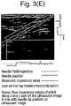
- FIG. 3(E)Rather than displaying the impedance value overlaid on the ultrasound image, it is also possible, as illustrated in Figure 3(E) to display the impedance values either colour-coded or charted alongside the ultrasound image. As indicated in Figure 3(E) to assist interpretation it is advantageous if the values are displayed along two orthogonal sides of the ultrasound image to allow the user to see the visual alignment between tissue boundaries in the ultrasound image and large changes in impedance value.
- the charted or colour-coded valuesare displayed in line with the position of the tip of the tool 5 projected onto the orthogonal sides of the image display.
- Figures 3(B), (C), and (D)illustrate the superimposition of transparent colour over the ultrasound image
- image attributesFor example the greyscale value, or a single coloured greyscale scheme (i.e. ranging from black to the single colour of interest, e.g. red, over 256 different values) can be used.
- One procedure which can be assisted by the systems of the inventionis that of delivering an epidural anaesthetic.
- the cliniciancan see bones in the spinal column and muscle and (sometimes) the dura in the ultrasound image.
- the magnetometric needle trackingallows the clinician to see the progress of the needle so that the needle tip can be brought quickly and easily close to the dura.
- the displayed impedance valuegives the clinician confirmation of when the needle breaks the dura and enters the epidural space and confirmation that the needle has not advanced too far.
- the ultrasound and magnetometric needle trackingcan be used in combination to bring the needle tip close to the nerve.
- the impedance valueallows the clinician to confirm whether or not the tip of the needle is touching or inside the nerve before any anaesthetic is injected.
- the impedance valuealso indicates whether the needle has punctured a blood vessel and it will indicate whether the needle has passed through facia compartments surrounding nerves - the failure to do so is a common reason for the failure of many femoral nerve blocks.
- the impedance valuecan indicate to the user whether or not the needle is inside or outside a tumour thus allowing greater accuracy in the collecting of material.
- the inventionis also useful for training purposes as the colour-coding of tissue at the tip of the needle according to the impedance measurement and thus tissue type, allows less experienced users clear indications linking what they are seeing on the ultrasound image to the anatomy of the patient.
- the electrode on the tool 5primarily provided for the impedance measurement, it is also possible to use it to supply electrical stimulation. For example it is possible to measure nerve conduction by applying an electrical signal to the electrode 7 while it is in contact or close to a nerve. If the nerve is blocked properly (i.e. the anaesthetic has had the desired effect) the patient will not feel any sensation.
Landscapes
- Health & Medical Sciences (AREA)
- Life Sciences & Earth Sciences (AREA)
- Engineering & Computer Science (AREA)
- Surgery (AREA)
- Animal Behavior & Ethology (AREA)
- General Health & Medical Sciences (AREA)
- Biomedical Technology (AREA)
- Heart & Thoracic Surgery (AREA)
- Veterinary Medicine (AREA)
- Public Health (AREA)
- Molecular Biology (AREA)
- Medical Informatics (AREA)
- Nuclear Medicine, Radiotherapy & Molecular Imaging (AREA)
- Pathology (AREA)
- Physics & Mathematics (AREA)
- Biophysics (AREA)
- Radiology & Medical Imaging (AREA)
- Anesthesiology (AREA)
- Robotics (AREA)
- Hematology (AREA)
- Human Computer Interaction (AREA)
- Ultra Sonic Daignosis Equipment (AREA)
- Magnetic Resonance Imaging Apparatus (AREA)
Description
- The present invention relates generally to the field of medical devices and in particular to a system for improving image guided procedures such as needle or catheterisation procedures.
- There are numerous medical procedures that involve the insertion of a medical tool or instrument, such as a needle, cannula, catheter or stylet, into a subject's body, e.g. minimally-invasive surgical procedures, regional anaesthesia, detection of bio-electrical signals, electrical stimulation for diagnosis or treatment, vascular access, fine needle aspiration, musculoskeletal injections and so on. In such procedures it is generally necessary to guide the medical tool properly to the desired position in the subject's body and it can also be beneficial to monitor or track the medical tool position to ensure that it remains at the desired location. In general it is very difficult for the user to determine the exact position of the tip of the medical tool and thus to be sure whether it is in the desired place, for example adjacent a nerve, or whether it has undesirably penetrated something else, for example a blood vessel.
- It has been proposed to use x-ray techniques for needle guidance by providing the clinician with an x-ray image of the needle in the body. However in view of the risks associated with exposure to electromagnetic radiation, it is not possible to provide a continuous guidance during insertion of the medical tool and so a series of snapshots are relied upon, which does not give optimal guidance.
- More recently the use of ultrasound imaging to guide needle and catheterisation procedures has been proposed. Ultrasound imaging is advantageous compared to x-ray techniques because of the lack of exposure to electromagnetic radiation, and ultrasound probes are easily manipulatable to image many different parts of the body. However ultrasound imaging has two main challenges: firstly that the interpretation of ultrasound images is rather difficult, and secondly that needles do not show-up particularly reliably or visibly in the ultrasound image.
- In more detail, ultrasound images provide only grayscale cross-sectional planes at a range of angles through the body depending on how the ultrasound transducer is applied. Traditional teaching of anatomy to doctors is in only six standard planes of the body and anatomic parts are typically coloured in diagrams to identify nerves, arteries, muscle, tissue etc. Therefore identifying anatomy clearly in ultrasound images requires a significant amount of learning and experience. This is a problem in extending the use of ultrasound imaging to the increasing variety of minimally-invasive surgical techniques where it is desirable if the practitioners performing the technique can do the ultrasound imaging themselves, rather than have to rely on a skilled radiologist. Further, for certain parts of the body ultrasound images intrinsically do not show the relevant anatomy very well. For example in the case of supra-clavicular nerve blocks involving the injection of anaesthetic around a nerve, studies have shown that in up to 20% of patients' blood vessels are found amongst the nerve bundles. In an ultrasound image both nerves and blood vessels are represented as black disks surrounded by white circles and so differentiation can be difficult meaning that it is difficult for the clinician to know exactly where the needle tip is. Similarly, when performing spinal injections, e.g. epidurals, ultrasound images show only muscle and bone and cannot penetrate bone, so it cannot see beyond the dura (the outermost of the three layers of membranes surrounding the spinal cord). Further the surface of the bone is only seen at a narrow range of angles. Therefore ultrasound image quality is very poor around the spine. However in the epidural anaesthetic injection, it is necessary for the needle to inject into the epidural space, but not to advance further and puncture the dura. On the other hand for a spinal anaesthetic, penetration of the dura is required to allow injection into the subarachnoid space. Ultrasound imaging is not capable of determining the difference between these two cases.
- As to the problem of needle visibility, the ultrasound image acquisition plane is thin - of the order of 1mm thick, and so if the needle is out of that plane it will not be imaged. Further, even when the needle is in the imaging plane, because the echogenicity of standard needles is poor at high angles of incidence, the needle may not be particularly visible. It has been proposed to produce echogenic needles which make the needle more visible to ultrasound imaging devices. However these only help when the needle is well-aligned with the imaging plane. Similarly techniques for image processing and ultrasound beam steering help only when the needle is well-aligned with the imaging plane and do not work well for angles of incidence greater than 45 degrees.
- Various needle tracking technologies have been proposed based either on a needle guide fitted to an ultrasound probe, e.g.
US-B2-6,690,159 orWO-A-2012/040077 , or based on the transmission and reception of electromagnetic information, e.g.US-A-2007-027390 ) but have functional and accuracy limitations which means that the needle tip position is not exactly known in every clinical circumstance. Typical accuracies are of the order of 2mm, which can mean the difference between the needle tip being inside or outside a nerve. Further they often require the use of heavily modified or new equipment which is unwelcome to clinicians and to institutions with relatively rigid purchasing regimes. - Most often, therefore, practitioners rely on their skill and experience to judge what type of tissue is being penetrated as the needle or other medical tool is inserted. They may rely on sound, the touch and feel of the physical resistance to the medical tool and sudden changes in resistance, and changes in resistance to the injection of air or fluids. Developing this level of skill and experience, though, is time-consuming and difficult and as there is an anatomical variation from patient to patient, the procedures inevitably entail some risks.
US-A1-2004/0097805 discloses an image guided navigation system which includes an ultrasound imagining probe or x-ray imaging system, a magnetic field generator and a catheter including magnetic field sensing coils. The catheter may be provided with an electrode for detecting tissue impendence.WO-A1-2012/058461 discloses a system and method for guiding a catheter or other medical device to a target destination within the vasculature of a patient via bio impendence measurements. The system includes a sensor module for positioning on the chest of the patient and detecting a magnet-equipped stylet which can be passed down the catheter, and an ultrasound imaging probe.US-B2-6678552 discloses an impedance sensing biopsy needle which includes an array of electrodes to detect the impedance of body tissue in contact with the biopsy needle. The needle may be monitored by an ultrasound imaging system and impedance readings from the needle may be overlaid on the ultrasound image of the biopsy needle. The preamble of claim 1 is based on the system ofUS6678552 .- In summary, although ultrasound guidance has improved some needling procedures, there are still significant difficulties and it cannot be used for many procedures. This is a major barrier to its widespread use, particularly its use by practitioners who are not medical imaging specialists, such as anaesthetists, surgeons, pathologists, emergency physicians etc.
- Accordingly, the present invention provides an improved system for image-guided procedures which combines ultrasound imaging of the subject's internal anatomy with tracking of the tissue-penetrating medical tool and display of the tracked position on the displayed anatomical image, together with making available to the user a third source of information based on a measurement of a bio-electrical property of the tissue being penetrated, the electrical property comprises the electrical impedance, and preferably it is displayed on the same display as the anatomical image, either overlaid on the image or alongside it. For example the impedance value may be displayed as a chart or colour coding along the displayed needle position or path on the anatomical image.
- Interest and experimentation in the electrical properties of tissue began in the late 1800s. It is now well known that different tissue types have different electrical impedance/frequency response curves. It has been proposed, for example in
WO2009/019707 to use a hand-held electrical device provided with a needle carrying two electrodes to measure the impedance of tissue inside a body but this special device gives only one-dimensional information about the tissue at the tip of the needle with no relative anatomical information. A technique known as electrical impedance tomography (EIT) has also been proposed which uses an array of electrodes on the surface of the body to reconstruct an impedance distribution within the body. This technique requires multiple electrodes, and the analysis of the signals to reconstruct the impedance distribution is highly complex. The spatial resolution of the technique is limited and so the anatomy is not clear in the images produced. Further, typically only a two-dimensional image is obtained of an area parallel to the body's surface and no information about depth is obtained. The images obtained also change significantly with the frequency at which impedance is measured, and introducing metal surgical devices into the body while acquiring image data would change the impedance fields being measured and change the images. Thus the main focus of EIT is on non-interventional medical applications, such as diagnostics and in fact there is still some doubt over its diagnostic capability. At present it is best seen as an additional imaging modality for use in breast cancer diagnosis. - The present invention combines measurement of impedance of the tissue in an interventional surgical procedure with ultrasound imaging and magnetic tool tracking to overcome the disadvantages above and provide the clinician with an enhanced picture of the interventional procedure.
- In more detail the invention provides a system as defined in claim 1.
- The medical imaging system comprises ultrasound imaging, more preferably the medical imaging system is freehand ultrasound.
- At least one second electrode is provided in contact with the subject, this may be on the tissue-penetrating medical tool or on another tissue-penetrating medical tool.
- The electrical system may be connected to the processor and display to display the measured impedance with the anatomical image on the display. The processor and display may be adapted to display a chart of the measured impedance over the display of the position of the tissue-penetrating medical tool in the anatomical image. The processor and display may be adapted to display the measured impedance by setting a display attribute in the anatomical image according to the value of the measured impedance. The processor and display may be adapted to set display attributes along the displayed position of the tissue-penetrating medical tool in the anatomical image according to the value of the measured impedance. The processor and display may be adapted to set display attributes at the displayed position of the insertion end of the tissue-penetrating medical tool in the anatomical image according to the value of the measured impedance. The display attribute set may be the colour or grayscale value. The processor may be adapted to determine a tissue type from the value of the measured impedance and to display the anatomical image with areas colour coded according to tissue type using standard medical anatomy colour coding.
- The processor and display may be adapted to display a chart of the measured impedance alongside the anatomical image. The processor and display may be adapted to display the change of measured impedance as the tissue-penetrating medical tool is moved through the subject's body.
- The tissue-penetrating medical tool comprises a needle or cannula. The first electrode may be provided at the tip of the needle or canula. A second electrode may be provided on a stimulating catheter for insertion through the needle or cannula. A second electrode may be provided on a needle of different gauge for insertion into the needle or cannula. A second electrode may be provided on a stylet for insertion into the needle or cannula. A second electrode is provided on the insertion end of the needle or cannula spaced from the first electrode.
- Thus with the invention the fact that the tissue-penetrating medical tool may have a low echogenecity is overcome by using magnetic position detection, by magnetising the tool and using an array of magnetometers on the ultrasound transducer to detect the field from the magnetised tool. The magnetically detected position and/or track of the tool is then displayed in the ultrasound image. Furthermore, the tool is provided with an electrode at its insertion end, for example at or near the tip of the tool, which is exposed for electrical contact with the tissue being penetrated so that by use of an electrical power supply and impedance meter, the impedance between the electrode at the insertion end of the tool and a second electrode in contact with the subject, and positioned at or near the insertion end of the tool, can be measured. This gives an indication of the impedance of the tissue, and thus of the tissue type, at and around the insertion end of the tool.
- Preferably the output of the impedance meter is connected to the processor and display so that the measured impedance can be displayed with the ultrasound image. The impedance values may be displayed as a number or more preferably as a chart showing the variation in impedance as the tool is inserted. The chart may be displayed alongside the ultrasound image, or more preferably overlaid on the ultrasound image along the displayed position or track of the tool. Alternatively, or in addition, a display attribute of the ultrasound image, especially along the position or track of the tool may be set in accordance with the measured impedance, for example it may be colour-coded or the greyscale value varied. This may provide a colour or other image-attribute overlay on the ultrasound image.
- If the tissue penetrating medical tool is out of the imaging plane of the ultrasound transducer then the processor and display may be adapted to show a position of the tool projected into the ultrasound imaging plane. The fact that it is a projected position can be indicated by visually distinguishing it from an actual position, for example by showing it dotted or in a different colour.
- It is known that different tissue types have different electrical impedances and it is possible, therefore, to determine the tissue type from the electrical impedance. Consequently the system may be adapted to determine the tissue type from the measured impedance value and then to colour-code areas of the ultrasound image using colour-coding typically used in medical anatomy texts.
- The tissue-penetrating medical tool can be a standard electrically-stimulating needle which has a built-in electrode at the distal, insertion end and electrical connections at the proximal end.
- The second electrode is provided on the tissue-penetrating tool itself, at or near the insertion end but spaced and insulated from the first electrode so as to provide a measurement of the impedance of the tissue at or around the tip of the tool. The second electrode may be provided on a second insertable instrument such as a second needle of narrower gauge which can be inserted down the lumen of a first needle, on a stylet for insertion into the lumen of the medical tool or on a catheter for insertion through the medical tool. The invention may, therefore, use one of the standard electrically-stimulating catheters which include a built-in electrode at their distal end.
- The electrical power supply may be adapted to provide DC or AC power and at a selectable number or range of frequencies so that the tissue impedance can be measured with DC or at a range of frequencies. Alternatively the frequency may be scanned over a range, or time-domain pulses which are shaped to comprise plural frequency domain components can be applied to measure the response at plural frequencies simultaneously.
- The invention therefore makes available to the clinician the image information, the detected position information and impedance data on the tissue being penetrated. The delivery and presentation to the clinician of these three sources of information make the surgical procedure much safer. Further, it achieves this without substantial modification of the instruments used by the clinician and thus without needing substantial modification of the surgical procedures.
- The presence of the first electrode on the medical tool also allows electrical stimulation of the tissue or electrical treatment to be carried out. For example, by applying an electrical stimulus to nerves the nerve conduction can be measured to give an indication of the effectiveness of an anaesthetic block.
- The impedance measurements can be used in combination with the ultrasound image to aid image processing of the ultrasound image. For example it is possible to use the impedance information, together with ultrasound information, to segment the displayed image into different tissue types.
- The invention may be combined with the delivery of ultrasound contrast agents and the impedance measurements may be used, rather than detecting the subject's tissue, to detect objects (screws, plastic, surgical devices), materials (silicone etc.) or other tissue modifications inside the subject's body.
- The invention will be further described by way of examples with reference to the accompanying drawings in which:-
FIG. 1 is a schematic diagram of an overall system;Fig. 2(A) schematically illustrates an unclaimed example of a tissue-penetrating medical tool;FIG. 2 (B) to (E) schematically illustrate different tissue-penetrating medical tools usable in the system of the invention;FIGS. 3 (A) to (E) illustrate different image displays according to embodiments of the invention;FIG. 4 schematically illustrates a magnetometric detector according to one embodiment of the invention; andFIG. 5 schematically illustrates a base station for the magnetometric detector ofFig. 4 .- As shown in
Figure 1 the system comprises an ultrasound imaging system 1 including anultrasound transducer 2, processor 3 anddisplay 4. The system also comprises a tissue-penetratingmedical tool 5 such as a needle or cannula which is provided at itsinsertion end 6 with anelectrode 7, theelectrode 7 being connected to animpedance meter 8 and source of electrical power 9. To complete the electrical circuit through the subject's body 10 asecond electrode 11 is provided in contact with the subject's body. InFigure 1 an unclaimed arrangement is illustrated in which thesecond electrode 11 is illustrated schematically as a skin-adhering electrode, though other possibilities for positioning the second electrode on thetool 5 in accordance with the invention will be discussed below. Theimpedance meter 8 and electrical power source 9 may be in a combined off-the-shelf impedance analyzer which has an onboard frequency generator which can excite complex impedance of the subject's tissue with a known frequency and which also analyses the response signal with a onboard digital signal processor that outputs as data the real and imaginary parts of the impedance. - In accordance with the invention magnetic position detection to track the
tissue penetrating tool 5 will be described. Thus thetool 5 is magnetised and theultrasound transducer 2 is provided with amagnetometric detector 12 comprising an array ofmagnetometers 120. Thedetector 12 senses the magnetic field from thetool 5, together with the earth's magnetic field and any other background magnetic field, and the processor 3 is adapted to determine from the detected field the position and orientation of thetool 5 relative to thetransducer 2. This magnetically detected position is then displayed on thedisplay 4 together with the ultrasound image. - The ultrasound system 1 can be a standard two dimensional B-mode ultrasound system with the
standard ultrasound probe 2 being modified by the provision of themagnetometric detector 12. Theprocessor 4, which is connected to the ultrasound probe via a cable, drives theultrasound transducer 2 by sending electrical signals to cause it to generate ultrasound pulses and interpreting the raw data received from thetransducer 2, which represents echoes from the subject's body, to assemble it into an image of the patient's tissue. Themagnetometric detector 12 may be detachably attached to theultrasound transducer 2 and can be battery-powered or powered from the ultrasound system. Preferably positioning elements are provided on themagnetometric detector 12 to ensure that it is always attached in the same well-defined position and orientation. Themagnetometric detector 12 is connected by awireless connection 15 to abase unit 14 which is in wireless or wired (e.g. USB)communication 16 with the ultrasound processor 3 anddisplay 4. Thebase unit 14 can be integrated with, or some of its functions performed by, the ultrasound processor 3 or themagnetometric detector 12. As will be explained in more detail below, thebase unit 14 receives normalised measurements frommagnetometric detector 12 and calculates the position, or optionally the position and orientation, of themedical tool 5. Thebase unit 14 can also receive additional information such as the state of charge of the magnetometric detector's battery and information can be sent from thebase unit 14 to themagnetometric detector 12, such as configuration information. Thebase unit 14 forwards the results of its calculations, i.e. the position and, optionally, orientation, to the ultrasound image processor 3 for inclusion in the displayed ultrasound image of animage 17 of thetool 5. This will be explained in more detail below. - As illustrated in
Figure 1 , and in accordance with the invention, the system also measures the electrical impedance of the body tissue of the subject. Thus thetool 5 carries at its insertion end thefirst electrode 7 which is exposed to the subject's body tissue and is electrically connected viaimpedance meter 8 and power supply 9 to asecond electrode 11 to complete a circuit with the subject's body. Thetool 5 may, for example, be a standard electrical stimulating needle which includes a built-inelectrode 7. The power supply 9 may, as schematically illustrated, apply either DC or AC and, if AC, applies a single frequency or a range of frequencies, or a frequency sweep. It is also possible for the power supply 9 to apply electrical pulses to give an instantaneous range of frequencies thus measuring the response at different frequencies simultaneously. Theimpedance meter 8 measures the impedance and digitises the value fortransmission 13 to the ultrasound processor 3. Theimpedance analyzer components 8 and 9 are in practice preferably integrated into a single unit. - Although the use of the
base station 14 andimpedance analyzer components 8 and 9 separate from the ultrasound system 1 is advantageous in requiring less modification of the ultrasound system 1, it will be appreciated that any of these can be integrated into the ultrasound system 1 with the processor 3 taking-over the functions of theprocessor 180 and the control and analysis functions of theimpedance analyzer components 8 and 9. Themagnetometric detector 12 can then be in direct communication with the ultrasound system 1 either via wireless link or using the same physical cable as theultrasound probe 2. Figure 1 schematically illustrates the tissue-penetrating medical tool as a standard nerve stimulating needle used in an unclaimed arrangement in combination with a standard skin-adheringelectrode 11.Figure 2(A) shows the insertion end of the needle in more detail with theelectrode 7 on the side of the needle at its tip. Configurations in accordance with the invention are, however, possible as illustrated inFigures 2(B) to (E). Figure 2(B) illustrates aneedle 5 in which the second electrode 11' is also positioned at or near the needle tip. As illustrated it is on the opposite side from thefirst electrode 7, though it can be positioned on the same side, spaced along the needle wall from thefirst electrode 7.Figure 2(C) illustrates an embodiment in which two standard stimulating needles of different gauges are used, one inside the other. Thus lumen of theneedle 5 carrying thefirst electrode 7 is occupied by a secondstandard stimulating needle 50 which carries the second electrode 11' at its insertion end. This arrangement with two concentric needles allows the injection of liquids at the same time as impedance measurements.Figure 2(D) illustrates an embodiment in which the second electrode 11' is positioned on the insertion end of a standardelectrically stimulating catheter 60 which is inserted down the lumen of theneedle 5.Figure 2(E) illustrates an embodiment in which the second electrode 11' is positioned on the distal end of astylet 70 passed down the lumen of theneedle 5.- It is, of course, necessary that the
electrodes 7 and 11' are insulated from the material of thetool 5 when the tool is electrically conductive. Further, in the concentric arrangements ofFigures 2(C), (D), and (E) either the inside of thetool 5 or the outside of the inner needle, stylet or catheter can be electrically insulated. - The electrical connections to the power supply 9 and
impedance meter 8 are preferably provided at the proximal end of thetool 5 in the same way as for a standard electrical stimulation needle or catheter. - It will be appreciated that whereas the embodiment of
Figure 2(A) measures the impedance along the path between thefirst electrode 7 and theskin electrode 11, the embodiments ofFigures 2(B) to 2(E) measure the electrical impedance closely in the vicinity of the tip of thetool 5 by virtue of the first and second electrodes being positioned closed together in the tissue into which the tool is being inserted. The embodiment ofFigure 1 is therefore well-suited to detecting and indicating changes impedance as the tool is inserted, which may be sufficient to inform clinician performing the insertion procedure. In other words the clinician may simply be interested to note the changes in tissue type as the tool is inserted, without needing to know the absolute value of the impedance of the tissue at the tool tip. On the other hand the embodiments ofFigures 2(B) to 2(E) can give an absolute measurement of the impedance of the tissue at the tool tip and this impedance value can be converted into a tissue type by referring to measured impedances of different tissue types, for example as found in:Herman et al, "Specific resistance of body tissues", Circulation Research, volume IV, November 1956. - Optionally where the impedance is measured at a range of frequencies it is possible to compress the different values into a single impedance metric value for display to the user.
- The
magnetometric detector 12 and the way in which the position of the magnetisedtool 5 compared to theultrasound probe 2 are calculated will now be explained in more detail. These techniques are described in our co-pending International (PCT) patent applicationPCT/EP2011/065420 - The components of the
magnetometric detector 12 are shown schematically in greater detail in the block diagram ofFigure 4 . Themagnetometric detector 12 comprises an array 100 or two or more (e.g. four) magnetometers 120 (not shown inFigure 4 ) whose outputs are sampled by amicroprocessor 110. Themicroprocessor 110 normalizes the measurement results obtained from the magnetometer array 100 and forwards it to atransceiver 115 with anantenna 130 which, in turn transmits the information to thebase unit 14. In a modified version of this embodiment, themagnetometric detector 12 is provided with a multiplexer rather than with amicroprocessor 110 and the normalization is performed by aprocessor 180 in thebase unit 14. - Each
magnetometer 120 in the array 100 of magnetometers measures the components


respective magnetometer 120 in three linearly independent directions. Themicroprocessor 110 transforms these raw values:


magnetometers 120 with their respective normalisation matrix and adding a normalisation offset vector such that the resultbk, for each magnetometer provides the components of the magnetic field in the same orthogonal spatial directions with identical gain. Thus, in a homogenous magnetic field, all magnetometers always provide identical values after normalisation regardless of the strength or orientation of the homogenous magnetic field. - All magnetometers should measure equal values when exposed to a homogeneous field. For example, a magnetometer rotated in the homogeneous terrestrial magnetic field should, depending on the orientation of the magnetometer, measure varying strengths of the components of the magnetic field in the three linearly independent directions. The total strength of the field, however, should remain constant regardless of the magnetometer's orientation. Yet, in magnetometers available on the market, gains and offsets differ in each of the three directions. Moreover, the directions oftentimes are not orthogonal to each other. As described for example in
US 7 275 008 B2 - With a set of sensors, additional steps need to be taken to assure that the measurements of different sensors are identical with each other. To correct this, preferably, set of a gain normalisation matricesMk and normalisation offset vectorsβk for each position k are determined which transform the magnetometer's raw resultsak into a normalized resultbk:

- Such a set of gain matricesMk can be obtained by known procedures, for example the iterative calibration scheme described inDorveaux et. al., "On-the-field Calibration of an Array of Sensors", 2010 American Control Conference, Baltimore 2010.
- By virtue of the defined transformation,bk provides the strength of the component of the magnetic field in three orthogonal spatial directions with equal gain. Moreover, it is ensured that these directions are the same for all magnetometers in the magnetometric detector. As a result, in any homogeneous magnetic field, all magnetometers yield essentially identical values.
- The normalisation informationMk andβk for each magnetometer as obtained in the calibration step can be stored either in the
magnetometric detector 12 itself or in thebase unit 14. Storing the information in themagnetometric detector 12 is preferred as this allows easy exchange of the magnetometric detector 12without the need to update the information in the base unit. Thus, in a preferred embodiment of the invention, the outputs of the magnetometers of the magnetometric device are sampled and their results are normalised in themagnetometric detector 12. This information, possibly together with other relevant information, is transmitted to thebase unit 14 for further analysis. - In another embodiment of the invention, the transformation can be another, more general non-linear transformationbk=F(ak).
- In addition to the above calibration method, another calibration method is applied which employs an inhomogeneous magnetic field to obtain the relative spatial locations of the magnetometric detector's magnetometers. While standard calibration methods utilize a homogenous magnetic field to (a) align the measurement axis of the magnetometers orthogonally, (b) cancel the offset values and (c) adjust to equal gain, it is of further advantage to the described systems that also the precise relative spatial locations of the magnetometers are available. This can be achieved by an additional calibration step in which the magnetometric detector is subjected to a known inhomogeneous magnetic field. Preferably, comparing the obtained measurements at the various positions to the expected field strengths and/or orientations in the assumed locations, and correcting the assumed locations until real measurements and expected measurements are in agreement, allows for the exact calibration of the spatial positions of the sensors.
- In a variation of the latter calibration method, an unknown rather than a known homogeneous field is used. The magnetometers are swept through the unknown magnetic field at varying positions, with a fixed orientation. With one of the magnetometers supplying a reference track, the positions of the other magnetometers are adaptively varied in such a way that their measurements align with the measurements of the reference unit. This can be achieved for example by a feedback loop realizing a mechano-magnetic-electronical gradient-descent algorithm. The tracks used in this inhomogeneous field calibration can be composed of just a single point in space.
- The
base station 14 shown schematically in greater detail inFigure 5 receives the normalised positional information from themagnetometric detector 12 through itsreceiver 160 withantenna 170 and forwards the information to aprocessor 180. There, the normalized results of the measurements are combined to derive the position (or position and orientation) of thetool 5. For this purpose, the valuesbk are used to fit a modelck(p) of the combined magnetic field originating from themagnetic tool 5 and the terrestrial magnetic field. The unknown parametersp in this model are the tool's location I relative to theultrasound transducer 2, it's length and orientationd and it's magnetic coercivitym as well as the terrestrial magnetic fieldE:
- The modelck(p) comprises the normalized components


- Suitable minimization techniques are for example gradient-descent algorithms as well as Levenberg-Marquardt approaches. Moreover, Kalman filter techniques or similar iterative means can be utilized to continuously perform such an operation.
- If the
tool 5 is sufficiently rigid, i.e. it bends only slightly, it can be approximated as a straight hollow cylinder. The magnetic field of such cylinder is equivalent to that of opposite magnetic charges (i.e. displaying opposite magnetic force) evenly distributed on the end surfaces of the cylinder, i.e. two circular rings at the opposite ends of the tools, the rings having opposite magnetic charge. In view of the small diameter of thetool 5, the charges can be further approximated by two magnetic point charges at the opposite ends of thetool 5. Thus, according to the model, the magnetic field of atool 5 extending along the vectord is measured from a positionrk is:
- Here |rk| and |rk+d| indicate the absolute values of the vectorsrk andrk + d, respectively. The positionsrk can be converted to the locationI of the
tool 5 relative to theultrasound transducer 2 with the help of the known positions of themagnetometers 120 in themagnetometric detector 12 and the position of themagnetometric detector 12 relatively to theultrasound transducer 2. Consequently, further considering the terrestrial magnetic fieldE, the components of the magnetic field according to the model amount to:
- Note that in contrast to many known approaches the above model does not assume the field of the needle to be a dipole field. This would be an oversimplification as the magnetometric detectors in general are too close to the needle as compared to the length of the needle to make a dipole field a valid approximation.
- The needle position obtained by fitting the model to the measured magnetic field valuesbk detected by the
magnetometers 120 as described above is then forwarded vialink 16 to the processing unit 3. There, it is superimposed on the image of the tissue as obtained from thehandheld ultrasound transducer 2. - If the
tool 5 is in the imaging plane of theultrasound transducer 2 the needle can be displayed as a solid line as illustrated schematically inFigure 1 . It is possible, however, that the needle is not in the ultrasound imaging plane. In such a case it is possible to display a position of the needle as projected onto the ultrasound image plane and to indicate in the display that it is a projected position by changing its display style. For example it can be displayed dotted and/or in a different colour. The tool is always visualised as a line, the end of which corresponds to the tool's tip. It is possible for the colour or display style to change depending upon whether the tool is in front of behind the imaging plane, and indeed if it cuts the imaging plane, parts behind can be displayed in one way and parts in front in another way. - It is also possible to display the whole expected needle track on the image display, this being a straight line extension of the tool's extent. Where anatomical features can be identified in the ultrasound image it is also possible to highlight the intersection of the needle track with these features, for example by displaying a circle or rectangle on the intersection.
- Although in
Figure 1 themagnetometers 120 are displayed in an array across the front of theultrasound transducer 2, it is also possible for them to be arranged in different ways on theultrasound transducer 2. - Optionally the
transducer 2 can also be provided with an inertial measurement unit which measures the position and orientation of the transducer by monitoring its acceleration from an initial position. - The
magnetic tool 5 is at least partly a permanent magnet. - The magnetisation may be provided by a magnetic coating, preferably a permanent magnetic coating. For this purpose, it may for example comprise permanent magnetic particles, more preferably nanoparticles. A "nanoparticle" is a particle that in at least two spatial dimensions is equal to or smaller than 100 nm in size.
- In one embodiment of the invention, tool has an essentially uniform magnetization. In another embodiment, the magnetization is non-uniform in at least one dimension, i.e. the magnetic moment varies in magnitude and/or direction as a function of the location on the tool, thereby creating a one- or more-dimensional magnetic pattern, e.g. similar to the pattern of a conventional magnetic strip (at least one-dimensional) or disk (two-dimensional) as it is used for the storage of information e.g. on credit cards. In a preferred embodiment of the invention, a one-dimensional magnetic pattern may be recorded along the length of the tool. Advantageously, such a pattern can be useful to identify the tool. Also, by marking certain parts of the tool with different magnetic codes, these parts can be distinguished. It is an achievable advantage of this embodiment of the invention that the position and/or orientation of the tool can be better determined, as individual parts of the tool can be identified and individually tracked with respect to their position and/or orientation. In particular, advantageously, a varying shape of the tool, for example a needle bending under pressure, can be tracked. Moreover, a deformed tool and/or its deformation or degree of deformation can be determined more easily.
Figures 3(A) to (E) illustrate different ways in which the impedance value measured by theimpedance meter 8 can be displayed by thedisplay 4. Of course the impedance value, or values as thetool 5 is inserted, can be displayed on a different display, for example associated with theimpedance meter 8 itself, but advantageously they are displayed with theultrasound image 4. Again, they may be displayed as simple numerical values, but it is particularly effective if they are displayed graphically aligned with thedisplay 4 or over the position or track of thetool 5.Figure 3(A) , therefore, illustrates the impedance value being displayed as a chart along the tool path, trajectory. It can be seen that although the impedance values vary continuously along the path, there are larger step-like changes associated with the tip of the tool crossing tissue boundaries visible in the ultrasound image. These step-like changes therefore act as confirmations that the tool tip is crossing these different tissue types.Figure 3(B) illustrates the measured impedance values colour-coded and displayed as an overlay on the tool position/trajectory, and again colour changes can be seen to align with the tissue boundaries visible in the ultrasound image itself.Figure 3(C) illustrates the conversion of the impedance values to tissue type and overlaying on the ultrasound image a colour-coding based on the colour-coding from standard medical anatomy texts in which, for example, nerves are yellow, arteries red, bone is white.Figure 3(D) illustrates a variation onFigures 3(B) and 3(C) in which the colour-coding is only displayed at the position of the tool tip.- Rather than displaying the impedance value overlaid on the ultrasound image, it is also possible, as illustrated in
Figure 3(E) to display the impedance values either colour-coded or charted alongside the ultrasound image. As indicated inFigure 3(E) to assist interpretation it is advantageous if the values are displayed along two orthogonal sides of the ultrasound image to allow the user to see the visual alignment between tissue boundaries in the ultrasound image and large changes in impedance value. The charted or colour-coded values are displayed in line with the position of the tip of thetool 5 projected onto the orthogonal sides of the image display. - While
Figures 3(B), (C), and (D) illustrate the superimposition of transparent colour over the ultrasound image, it is alternatively possible to use different image attributes to indicate the impedance value. For example the greyscale value, or a single coloured greyscale scheme (i.e. ranging from black to the single colour of interest, e.g. red, over 256 different values) can be used. - One procedure which can be assisted by the systems of the invention is that of delivering an epidural anaesthetic. Using the ultrasound imaging system the clinician can see bones in the spinal column and muscle and (sometimes) the dura in the ultrasound image. The magnetometric needle tracking allows the clinician to see the progress of the needle so that the needle tip can be brought quickly and easily close to the dura. The displayed impedance value gives the clinician confirmation of when the needle breaks the dura and enters the epidural space and confirmation that the needle has not advanced too far.
- As another example, in a regional anaesthesia procedure the ultrasound and magnetometric needle tracking can be used in combination to bring the needle tip close to the nerve. The impedance value allows the clinician to confirm whether or not the tip of the needle is touching or inside the nerve before any anaesthetic is injected. The impedance value also indicates whether the needle has punctured a blood vessel and it will indicate whether the needle has passed through facia compartments surrounding nerves - the failure to do so is a common reason for the failure of many femoral nerve blocks.
- In a needle aspiration procedure the impedance value can indicate to the user whether or not the needle is inside or outside a tumour thus allowing greater accuracy in the collecting of material.
- The invention is also useful for training purposes as the colour-coding of tissue at the tip of the needle according to the impedance measurement and thus tissue type, allows less experienced users clear indications linking what they are seeing on the ultrasound image to the anatomy of the patient.
- Although the electrode on the
tool 5 primarily provided for the impedance measurement, it is also possible to use it to supply electrical stimulation. For example it is possible to measure nerve conduction by applying an electrical signal to theelectrode 7 while it is in contact or close to a nerve. If the nerve is blocked properly (i.e. the anaesthetic has had the desired effect) the patient will not feel any sensation.


Claims (15)
- A system comprising:an ultrasound transducer (2) for transmitting ultrasound into a subject's body (10) and receiving ultrasound echoes from the body (10);a tissue-penetrating medical tool (5) comprising a needle or cannula and having an insertion end (6) for insertion into the body (10) of the subject;a first electrode (7) provided at the insertion end (6) of the tissue-penetrating medical tool (5), exposed for electrical contact with the subject's body (10);a second electrode (11) in electrical contact with the subject's body (10) and positioned at or near the insertion end (6) of the tissue-penetrating medical tool (5); andan electrical power supply (9) and an impedance meter (8) electrically-connected to the first electrode (7) and the second electrode (11) for measuring the impedance between the first electrode (7) and the second electrode (11);a processor (3) and display (4) for analysing the ultrasound echoes and displaying an ultrasound image of the body (10);characterized by:the tissue-penetrating medical tool (5) being magnetized;and by the system further comprising:a magnetic position detection system (12, 14) comprising an array of magnetometric sensors (120) positioned on the ultrasound transducer (2) for detecting the magnetic field originating from the magnetized tissue-penetrating medical tool (5) and adapted to calculate the position of the magnetised tissue-penetrating medical tool (5) in the body (10) of the subject relative to the ultrasound transducer (2);and wherein the processor (3) and display (4) are adapted to display on the ultrasound image the position of the tissue-penetrating medical tool (5) as detected by the position detection system (12, 14).
- A system according to claim 1 wherein the impedance meter (8) is connected to the processor (3) and display (4) to display the measured impedance with the ultrasound image on the display (4).
- A system according to claim 2 wherein the processor (3) and display (4) are adapted to display a chart of the measured impedance over the display of the position of the tissue-penetrating medical tool (5) in the ultrasound image or to display a chart of the measured impedance alongside ultrasound image.
- A system according to claim 2 wherein the processor (3) and display (4) are adapted to display the measured impedance by setting a display attribute in the ultrasound image according to the measured impedance value.
- A system according to claim 4 wherein the processor (3) and display (4) are adapted to set display attributes along the displayed position of the tissue-penetrating medical tool (5) in the ultrasound image according to the measured impedance value.
- A system according to claim 4 wherein the processor (3) and display (4) are adapted to set display attributes at the displayed position of the insertion end of the tissue-penetrating medical tool (5) in the ultrasound image according to the measured impedance value.
- A system according to claim 5 or 6 wherein the processor (3) and display (4) are adapted to set display attributes at a projected displayed position if the tissue-penetrating medical tool (5) is out of the ultrasound image plane.
- A system according to claim 4, 5, 6 or 7 wherein the processor (3) is adapted to determine a tissue type from the impedance value and to display the ultrasound image with areas colour coded according to tissue type using standard medical anatomy colour coding.
- A system according to any one of claims 2 to 8 wherein the processor (3) and display (4) are adapted to display the change of impedance as the tissue-penetrating medical tool (5) is moved through the subject's body (10).
- A system according to any one of the preceding claims wherein the first electrode (7) is provided at the tip of the tissue-penetrating medical tool (5).
- A system according to any one of the preceding claims wherein the tissue-penetrating medical tool comprises a stimulating catheter (60) and the second electrode (11) is provided on the stimulating catheter (60) for insertion through the needle or cannula (5).
- A system according to any one of claims 1 to 10 wherein the tissue-penetrating medical tool comprises a second needle (50), of different gauge, such as a stylet, for insertion into the needle or cannula (5), the second electrode (11) being provided on the second needle (50).
- A system according to any one of claims 1 to 10 wherein the second electrode (11) is provided on the insertion end of the needle or cannula (5) spaced from the first electrode (7).
- A system according to any one of the preceding claims wherein a plurality of second electrodes (11) are provided.
- A system according to any one of the preceding claims wherein the electrical power supply (9) is adapted to supply power over a range of AC frequencies and the impedance meter (8) is adapted to measure the impedance at a plurality of frequencies.
Priority Applications (1)
| Application Number | Priority Date | Filing Date | Title |
|---|---|---|---|
| PL14707828TPL2996556T3 (en) | 2013-03-05 | 2014-03-05 | System for image guided procedure |
Applications Claiming Priority (2)
| Application Number | Priority Date | Filing Date | Title |
|---|---|---|---|
| GBGB1303917.7AGB201303917D0 (en) | 2013-03-05 | 2013-03-05 | System for image guided procedure |
| PCT/EP2014/054276WO2014135592A1 (en) | 2013-03-05 | 2014-03-05 | System for image guided procedure |
Publications (2)
| Publication Number | Publication Date |
|---|---|
| EP2996556A1 EP2996556A1 (en) | 2016-03-23 |
| EP2996556B1true EP2996556B1 (en) | 2021-04-21 |
Family
ID=48142438
Family Applications (1)
| Application Number | Title | Priority Date | Filing Date |
|---|---|---|---|
| EP14707828.1AActiveEP2996556B1 (en) | 2013-03-05 | 2014-03-05 | System for image guided procedure |
Country Status (10)
| Country | Link |
|---|---|
| US (1) | US10434278B2 (en) |
| EP (1) | EP2996556B1 (en) |
| JP (1) | JP6549992B2 (en) |
| KR (1) | KR102245665B1 (en) |
| CN (1) | CN105025787A (en) |
| DK (1) | DK2996556T3 (en) |
| ES (1) | ES2871063T3 (en) |
| GB (1) | GB201303917D0 (en) |
| PL (1) | PL2996556T3 (en) |
| WO (1) | WO2014135592A1 (en) |
Families Citing this family (80)
| Publication number | Priority date | Publication date | Assignee | Title |
|---|---|---|---|---|
| EP2358278B1 (en) | 2008-12-08 | 2021-05-12 | Acist Medical Systems, Inc. | System and catheter for image guidance and methods thereof |
| ES2568225T3 (en) | 2011-09-06 | 2016-04-28 | Ezono Ag | Imaging probe and method to obtain position and / or orientation information |
| US9257220B2 (en) | 2013-03-05 | 2016-02-09 | Ezono Ag | Magnetization device and method |
| GB201303917D0 (en) | 2013-03-05 | 2013-04-17 | Ezono Ag | System for image guided procedure |
| US9459087B2 (en) | 2013-03-05 | 2016-10-04 | Ezono Ag | Magnetic position detection system |
| EP3169244B1 (en) | 2014-07-16 | 2019-05-15 | Koninklijke Philips N.V. | Intelligent real-time tool and anatomy visualization in 3d imaging workflows for interventional procedures |
| US10674933B2 (en)* | 2014-10-22 | 2020-06-09 | Biosense Webster (Israel) Ltd. | Enlargement of tracking volume by movement of imaging bed |
| EP3273894B1 (en)* | 2015-03-26 | 2023-03-15 | Biomet Manufacturing, LLC | Anatomic registration probes, systems and methods |
| EP3184071A1 (en)* | 2015-12-22 | 2017-06-28 | SpineMind AG | Device for intraoperative image-guided navigation during surgical interventions in the vicinity of the spine and the adjoining thoracic, pelvis or head area |
| EP3397184A1 (en)* | 2015-12-29 | 2018-11-07 | Koninklijke Philips N.V. | System, control unit and method for control of a surgical robot |
| US20200261155A1 (en)* | 2015-12-30 | 2020-08-20 | Koninklijke Philips N.V. | Image based robot guidance |
| US11344220B2 (en) | 2016-05-13 | 2022-05-31 | Becton, Dickinson And Company | Invasive medical device cover with magnet |
| US10980979B2 (en) | 2016-05-13 | 2021-04-20 | Becton, Dickinson And Company | Magnetic shield for medical devices |
| US10327667B2 (en)* | 2016-05-13 | 2019-06-25 | Becton, Dickinson And Company | Electro-magnetic needle catheter insertion system |
| US11109833B2 (en) | 2016-05-19 | 2021-09-07 | Acist Medical Systems, Inc. | Position sensing in intravascular processes |
| WO2017201287A1 (en) | 2016-05-19 | 2017-11-23 | Acist Medical Systems, Inc. | Position sensing in intravascular processes |
| US11413429B2 (en) | 2016-06-01 | 2022-08-16 | Becton, Dickinson And Company | Medical devices, systems and methods utilizing permanent magnet and magnetizable feature |
| US20170347914A1 (en)* | 2016-06-01 | 2017-12-07 | Becton, Dickinson And Company | Invasive Medical Devices Including Magnetic Region And Systems And Methods |
| US10583269B2 (en) | 2016-06-01 | 2020-03-10 | Becton, Dickinson And Company | Magnetized catheters, devices, uses and methods of using magnetized catheters |
| US11826522B2 (en) | 2016-06-01 | 2023-11-28 | Becton, Dickinson And Company | Medical devices, systems and methods utilizing permanent magnet and magnetizable feature |
| US11116419B2 (en) | 2016-06-01 | 2021-09-14 | Becton, Dickinson And Company | Invasive medical devices including magnetic region and systems and methods |
| US10898105B2 (en) | 2016-06-06 | 2021-01-26 | Temple University—Of the Commonwealth System of Higher Education | Magnetometer surgical device |
| US10032552B2 (en) | 2016-08-30 | 2018-07-24 | Becton, Dickinson And Company | Cover for tissue penetrating device with integrated magnets and magnetic shielding |
| US20190313941A1 (en)* | 2016-11-16 | 2019-10-17 | Avinger, Inc. | Methods, systems and apparatuses for displaying real-time catheter position |
| US11369410B2 (en) | 2017-04-27 | 2022-06-28 | Bard Access Systems, Inc. | Magnetizing system for needle assemblies including orientation key system for positioning needle tray in magnetizer |
| CN107049492B (en)* | 2017-05-26 | 2020-02-21 | 微创(上海)医疗机器人有限公司 | Surgical robot system and method for displaying position of surgical instrument |
| KR102016941B1 (en) | 2017-09-26 | 2019-09-02 | 주식회사 에프씨유 | Ultrasonic probe for optimum postion of magnetic sensor |
| US20190201142A1 (en)* | 2017-12-28 | 2019-07-04 | Ethicon Llc | Automatic tool adjustments for robot-assisted surgical platforms |
| EP3790461B1 (en) | 2018-05-10 | 2025-06-25 | University of Pittsburgh - Of the Commonwealth System of Higher Education | Sensing cannula systems |
| JP7237147B2 (en)* | 2018-08-23 | 2023-03-10 | コーニンクレッカ フィリップス エヌ ヴェ | Biometric measurement and quality assessment |
| US20200069285A1 (en)* | 2018-08-31 | 2020-03-05 | General Electric Company | System and method for ultrasound navigation |
| KR102166739B1 (en)* | 2018-11-13 | 2020-10-16 | 주식회사 에너지사이언스 | Biosignal Imaging Display System Using Biosignal Sensing Apparatus |
| KR102188176B1 (en)* | 2018-12-06 | 2020-12-07 | 한국 한의학 연구원 | Untrasonic Imaging Apparatus having acupuncture guiding function |
| CN109567906B (en)* | 2018-12-14 | 2020-04-24 | 清华大学 | Puncture needle and ultrasonic puncture device |
| US12178982B2 (en)* | 2019-01-18 | 2024-12-31 | Becton, Dickinson And Company | Intravenous therapy system for blood vessel detection and vascular access device placement |
| US11925333B2 (en) | 2019-02-01 | 2024-03-12 | Covidien Lp | System for fluoroscopic tracking of a catheter to update the relative position of a target and the catheter in a 3D model of a luminal network |
| US20200281561A1 (en) | 2019-03-05 | 2020-09-10 | Ethos Medical, Inc. | Systems, Methods, and Devices for Instrument Guidance |
| KR102757707B1 (en)* | 2019-04-11 | 2025-01-21 | 삼성메디슨 주식회사 | Ultrasonic probe and ultrasonic imaging apparatus having the same |
| US20220273188A1 (en)* | 2019-07-29 | 2022-09-01 | University Of Pittsburgh - Of The Commonwealth System Of Higher Education | Sensing cannula systems |
| US20220313102A1 (en)* | 2019-09-02 | 2022-10-06 | Osaka University | Paracentesis assistance system, paracentesis assistance method, and program |
| CN110507867B (en)* | 2019-09-04 | 2020-09-29 | 武汉中科科理光电技术有限公司 | Feedback type intelligent injector |
| US11633170B2 (en) | 2019-09-04 | 2023-04-25 | Bard Access Systems, Inc. | Systems and methods for ultrasound probe needle tracking status indicators |
| US11759166B2 (en) | 2019-09-20 | 2023-09-19 | Bard Access Systems, Inc. | Automatic vessel detection tools and methods |
| EP4042944A4 (en)* | 2019-09-30 | 2022-11-02 | TERUMO Kabushiki Kaisha | DIAGNOSTIC AID DEVICE, DIAGNOSTIC AID SYSTEM AND DIAGNOSTIC AID METHOD |
| JP2022552983A (en)* | 2019-10-17 | 2022-12-21 | コーニンクレッカ フィリップス エヌ ヴェ | Dynamic update of tissue images |
| US11191446B2 (en)* | 2019-11-27 | 2021-12-07 | Blossom Innovations, LLC | Devices, systems and methods for tissue analysis, locaton determination and tissue ablation |
| EP3909640A1 (en)* | 2020-05-12 | 2021-11-17 | Surgicen SLU | Medical device for spinal cord stimulation |
| US11877810B2 (en) | 2020-07-21 | 2024-01-23 | Bard Access Systems, Inc. | System, method and apparatus for magnetic tracking of ultrasound probe and generation of 3D visualization thereof |
| EP4185209A1 (en) | 2020-08-04 | 2023-05-31 | Bard Access Systems, Inc. | System and method for optimized medical component insertion monitoring and imaging enhancement |
| WO2022035760A1 (en) | 2020-08-10 | 2022-02-17 | Bard Access Systems, Inc. | System and method for generating vessel representations in mixed reality/virtual reality |
| CN111938700B (en)* | 2020-08-21 | 2021-11-09 | 电子科技大学 | Ultrasonic probe guiding system and method based on real-time matching of human anatomy structure |
| US11890139B2 (en) | 2020-09-03 | 2024-02-06 | Bard Access Systems, Inc. | Portable ultrasound systems |
| US11992363B2 (en) | 2020-09-08 | 2024-05-28 | Bard Access Systems, Inc. | Dynamically adjusting ultrasound-imaging systems and methods thereof |
| CN216257185U (en) | 2020-09-10 | 2022-04-12 | 巴德阿克塞斯系统股份有限公司 | Ultrasound Probes and Ultrasound Systems |
| WO2022067101A1 (en) | 2020-09-25 | 2022-03-31 | Bard Access Systems, Inc. | Minimum catheter length tool |
| WO2022072727A2 (en) | 2020-10-02 | 2022-04-07 | Bard Access Systems, Inc. | Ultrasound systems and methods for sustained spatial attention |
| EP4228516A1 (en) | 2020-10-15 | 2023-08-23 | Bard Access Systems, Inc. | Ultrasound imaging system for generation of a three-dimensional ultrasound image |
| WO2022082075A1 (en)* | 2020-10-17 | 2022-04-21 | The Board Of Trustees Of The Leland Stanford Junior University | Apparatuses and methods for assisting, confirming, and monitoring placement of catheters in patients |
| US11911140B2 (en) | 2020-11-09 | 2024-02-27 | Bard Access Systems, Inc. | Medical device magnetizer |
| CN114464394A (en) | 2020-11-10 | 2022-05-10 | 巴德阿克塞斯系统股份有限公司 | Devices, systems and methods for magnetizing medical devices while maintaining their sterility |
| CN216933458U (en)* | 2020-11-24 | 2022-07-12 | 巴德阿克塞斯系统股份有限公司 | Object recognition and needle guidance system |
| CN114569155A (en) | 2020-12-01 | 2022-06-03 | 巴德阿克塞斯系统股份有限公司 | Ultrasound imaging system and method for obtaining ultrasound image by the same |
| CN114569156A (en) | 2020-12-01 | 2022-06-03 | 巴德阿克塞斯系统股份有限公司 | Ultrasound imaging system and method for identifying one or more of a plurality of blood vessels |
| EP4258997A1 (en) | 2020-12-14 | 2023-10-18 | Bard Access Systems, Inc. | Securement of hands-free ultrasound probe |
| US12349983B2 (en)* | 2021-03-05 | 2025-07-08 | Bard Access Systems, Inc. | Systems and methods for ultrasound-and-bioimpedance-based guidance of medical devices |
| CN217960146U (en) | 2021-04-15 | 2022-12-06 | 巴德阿克塞斯系统股份有限公司 | Ultrasound imaging system |
| CA3214224A1 (en)* | 2021-05-21 | 2022-11-24 | Brian L. Norling | Electrical conductivity sensor system and device with real-time feedback |
| EP4358836A1 (en) | 2021-06-22 | 2024-05-01 | Bard Access Systems, Inc. | Medical device magnetizer system with indicators |
| EP4377976A1 (en) | 2021-07-26 | 2024-06-05 | Bard Access Systems, Inc. | Medical-device magnetizer systems and methods |
| CN115869006B (en)* | 2021-09-27 | 2025-08-26 | 深圳迈瑞生物医疗电子股份有限公司 | Ultrasonic imaging device and ultrasonic imaging method |
| CN116058873A (en) | 2021-11-03 | 2023-05-05 | 巴德阿克塞斯系统股份有限公司 | Interoperation optimization function through Doppler and image-based vessel discrimination |
| WO2023101707A1 (en) | 2021-12-02 | 2023-06-08 | Poplaw Steven | System for color-coding medical instrumentation and methods of use |
| CN114027937A (en)* | 2021-12-24 | 2022-02-11 | 上海益超医疗器械有限公司 | Devices that output drive signals to surgical instruments |
| CN114041877B (en)* | 2022-01-06 | 2022-04-01 | 南京惠积信息科技有限公司 | Three-dimensional catheter positioning system based on impedance information |
| US12433567B2 (en) | 2022-03-16 | 2025-10-07 | Bard Access Systems, Inc. | Ultrasound imaging system |
| US12207967B2 (en) | 2022-04-20 | 2025-01-28 | Bard Access Systems, Inc. | Ultrasound imaging system |
| US12102481B2 (en) | 2022-06-03 | 2024-10-01 | Bard Access Systems, Inc. | Ultrasound probe with smart accessory |
| US12137989B2 (en) | 2022-07-08 | 2024-11-12 | Bard Access Systems, Inc. | Systems and methods for intelligent ultrasound probe guidance |
| KR20240078091A (en) | 2022-11-25 | 2024-06-03 | 주식회사 에프씨유 | Ultrasonography simulation training device |
| WO2025165789A1 (en)* | 2024-01-29 | 2025-08-07 | Bard Access Systems, Inc. | Systems and methods for needle guidance |
Citations (2)
| Publication number | Priority date | Publication date | Assignee | Title |
|---|---|---|---|---|
| US20040097805A1 (en)* | 2002-11-19 | 2004-05-20 | Laurent Verard | Navigation system for cardiac therapies |
| WO2012058461A1 (en)* | 2010-10-29 | 2012-05-03 | C.R.Bard, Inc. | Bioimpedance-assisted placement of a medical device |
Family Cites Families (281)
| Publication number | Priority date | Publication date | Assignee | Title |
|---|---|---|---|---|
| JPS5373892A (en) | 1976-12-11 | 1978-06-30 | Kenkichi Tsukamoto | Improved needle and attached ampule |
| US4317078A (en) | 1979-10-15 | 1982-02-23 | Ohio State University Research Foundation | Remote position and orientation detection employing magnetic flux linkage |
| EP0419729A1 (en) | 1989-09-29 | 1991-04-03 | Siemens Aktiengesellschaft | Position finding of a catheter by means of non-ionising fields |
| US5055813A (en) | 1990-06-28 | 1991-10-08 | Johnson Terry R | Magnetization/demagnetization device |
| EP0488987B1 (en) | 1990-11-26 | 1996-01-31 | Michael Dr. Truppe | Method for representing moving bodies |
| US9290146B2 (en) | 1992-05-05 | 2016-03-22 | Intelligent Technologies International, Inc. | Optical monitoring of vehicle interiors |
| US5902238A (en) | 1993-09-14 | 1999-05-11 | University Of Washington | Medical tube and apparatus for locating the same in the body of a patient |
| US5425382A (en) | 1993-09-14 | 1995-06-20 | University Of Washington | Apparatus and method for locating a medical tube in the body of a patient |
| US5558091A (en) | 1993-10-06 | 1996-09-24 | Biosense, Inc. | Magnetic determination of position and orientation |
| AU1693095A (en) | 1994-08-19 | 1996-03-14 | Biosense, Inc. | Medical diagnosis, treatment and imaging systems |
| US6678552B2 (en) | 1994-10-24 | 2004-01-13 | Transscan Medical Ltd. | Tissue characterization based on impedance images and on impedance measurements |
| EP0788329B1 (en) | 1994-10-24 | 2006-12-06 | Mirabel Medical Systems Ltd. | Impedance imaging devices and multi-element probe |
| KR100462498B1 (en)* | 1994-10-24 | 2006-03-30 | 트랜스캔 리서치 앤드 디벨롭먼트 코포레이션 리미티드 | Impedance imaging devices and multi-element probe |
| US6690963B2 (en) | 1995-01-24 | 2004-02-10 | Biosense, Inc. | System for determining the location and orientation of an invasive medical instrument |
| US6246898B1 (en) | 1995-03-28 | 2001-06-12 | Sonometrics Corporation | Method for carrying out a medical procedure using a three-dimensional tracking and imaging system |
| EP0747016B1 (en) | 1995-06-05 | 2003-03-12 | Dennis W. Szymaitis | Electromagnetically detectable marked surgical object |
| US5944023A (en) | 1995-12-07 | 1999-08-31 | Sims Deltec, Inc. | Systems and methods for determining the location of an implanted device including a magnet |
| WO1997029710A1 (en) | 1996-02-15 | 1997-08-21 | Biosense, Inc. | Medical probes with field transducers |
| IL125755A (en) | 1996-02-15 | 2003-05-29 | Biosense Inc | Catheter calibration and usage monitoring system |
| US5767669A (en) | 1996-06-14 | 1998-06-16 | Ascension Technology Corporation | Magnetic field position and orientation measurement system with dynamic eddy current rejection |
| US5744953A (en) | 1996-08-29 | 1998-04-28 | Ascension Technology Corporation | Magnetic motion tracker with transmitter placed on tracked object |
| US5831260A (en) | 1996-09-10 | 1998-11-03 | Ascension Technology Corporation | Hybrid motion tracker |
| US6331181B1 (en) | 1998-12-08 | 2001-12-18 | Intuitive Surgical, Inc. | Surgical robotic tools, data architecture, and use |
| WO1998028039A2 (en)* | 1996-12-20 | 1998-07-02 | Ep Technologies, Inc. | Unified switching system for electrophysiological stimulation and signal recording and analysis |
| US6263230B1 (en) | 1997-05-08 | 2001-07-17 | Lucent Medical Systems, Inc. | System and method to determine the location and orientation of an indwelling medical device |
| US5879297A (en) | 1997-05-08 | 1999-03-09 | Lucent Medical Systems, Inc. | System and method to determine the location and orientation of an indwelling medical device |
| US6248074B1 (en) | 1997-09-30 | 2001-06-19 | Olympus Optical Co., Ltd. | Ultrasonic diagnosis system in which periphery of magnetic sensor included in distal part of ultrasonic endoscope is made of non-conductive material |
| US5953683A (en) | 1997-10-09 | 1999-09-14 | Ascension Technology Corporation | Sourceless orientation sensor |
| US5941889A (en) | 1997-10-14 | 1999-08-24 | Civco Medical Instruments Inc. | Multiple angle disposable needle guide system |
| US6073043A (en) | 1997-12-22 | 2000-06-06 | Cormedica Corporation | Measuring position and orientation using magnetic fields |
| US6052610A (en) | 1998-01-09 | 2000-04-18 | International Business Machines Corporation | Magnetic catheter tracker and method therefor |
| US8079982B1 (en)* | 1998-06-04 | 2011-12-20 | Biosense Webster, Inc. | Injection catheter with needle electrode |
| WO2000010456A1 (en) | 1998-08-02 | 2000-03-02 | Super Dimension Ltd. | Intrabody navigation system for medical applications |
| US6379307B1 (en) | 1998-09-16 | 2002-04-30 | Roy Filly | Adjustable needle guide apparatus and method |
| US6361499B1 (en) | 1998-09-16 | 2002-03-26 | Civco Medical Instruments Inc. | Multiple angle needle guide |
| JP4443672B2 (en)* | 1998-10-14 | 2010-03-31 | 株式会社東芝 | Ultrasonic diagnostic equipment |
| US8068897B1 (en) | 1999-03-01 | 2011-11-29 | Gazdzinski Robert F | Endoscopic smart probe and method |
| US7558616B2 (en) | 1999-03-11 | 2009-07-07 | Biosense, Inc. | Guidance of invasive medical procedures using implantable tags |
| AU3985400A (en) | 1999-04-15 | 2000-11-02 | Ultra-Guide Ltd. | Apparatus and method for detecting the bending of medical invasive tools in medical interventions |
| US6368280B1 (en) | 1999-04-30 | 2002-04-09 | Civco Medical Instruments Inc. | Endocavity needle guide apparatus and method |
| US6292678B1 (en) | 1999-05-13 | 2001-09-18 | Stereotaxis, Inc. | Method of magnetically navigating medical devices with magnetic fields and gradients, and medical devices adapted therefor |
| US7386339B2 (en) | 1999-05-18 | 2008-06-10 | Mediguide Ltd. | Medical imaging and navigation system |
| US6233476B1 (en) | 1999-05-18 | 2001-05-15 | Mediguide Ltd. | Medical positioning system |
| US6246231B1 (en) | 1999-07-29 | 2001-06-12 | Ascension Technology Corporation | Magnetic field permeable barrier for magnetic position measurement system |
| US6427079B1 (en) | 1999-08-09 | 2002-07-30 | Cormedica Corporation | Position and orientation measuring with magnetic fields |
| US6317616B1 (en) | 1999-09-15 | 2001-11-13 | Neil David Glossop | Method and system to facilitate image guided surgery |
| US6198956B1 (en) | 1999-09-30 | 2001-03-06 | Oti Ophthalmic Technologies Inc. | High speed sector scanning apparatus having digital electronic control |
| US6315724B1 (en) | 1999-10-19 | 2001-11-13 | Biomedicom Ltd | 3-dimensional ultrasonic imaging |
| US6493573B1 (en) | 1999-10-28 | 2002-12-10 | Winchester Development Associates | Method and system for navigating a catheter probe in the presence of field-influencing objects |
| US6379302B1 (en) | 1999-10-28 | 2002-04-30 | Surgical Navigation Technologies Inc. | Navigation information overlay onto ultrasound imagery |
| US7366562B2 (en) | 2003-10-17 | 2008-04-29 | Medtronic Navigation, Inc. | Method and apparatus for surgical navigation |
| US6172499B1 (en) | 1999-10-29 | 2001-01-09 | Ascension Technology Corporation | Eddy current error-reduced AC magnetic position measurement system |
| AU2001238012A1 (en) | 2000-02-01 | 2001-08-14 | Surgi-Vision, Inc. | Magnetic resonance imaging transseptal needle antenna |
| US6438401B1 (en) | 2000-04-28 | 2002-08-20 | Alpha Intervention Technology, Inc. | Indentification and quantification of needle displacement departures from treatment plan |
| US6310532B1 (en) | 2000-05-19 | 2001-10-30 | Cathy D. Santa Cruz | Multipurpose magnetizer/demagnetizer |
| WO2002000093A2 (en) | 2000-06-27 | 2002-01-03 | Insightec-Image Guided Treatment Ltd. | Registration of target object images to stored image data |
| US7809421B1 (en) | 2000-07-20 | 2010-10-05 | Biosense, Inc. | Medical system calibration with static metal compensation |
| US6716166B2 (en) | 2000-08-18 | 2004-04-06 | Biosense, Inc. | Three-dimensional reconstruction using ultrasound |
| US6690159B2 (en) | 2000-09-28 | 2004-02-10 | Eldec Corporation | Position indicating system |
| DE10051244A1 (en) | 2000-10-17 | 2002-05-16 | Philips Corp Intellectual Pty | X-ray free intravascular localization and imaging procedure |
| US20020103430A1 (en) | 2001-01-29 | 2002-08-01 | Hastings Roger N. | Catheter navigation within an MR imaging device |
| US6678546B2 (en)* | 2001-01-30 | 2004-01-13 | Fischer Imaging Corporation | Medical instrument guidance using stereo radiolocation |
| US7966057B2 (en) | 2001-02-06 | 2011-06-21 | Medtronic Vascular, Inc. | Methods and apparatus for guided transluminal interventions using vessel wall penetrating catheters and other apparatus |
| DE10115341A1 (en) | 2001-03-28 | 2002-10-02 | Philips Corp Intellectual Pty | Method and imaging ultrasound system for determining the position of a catheter |
| US6785571B2 (en) | 2001-03-30 | 2004-08-31 | Neil David Glossop | Device and method for registering a position sensor in an anatomical body |
| US6636757B1 (en) | 2001-06-04 | 2003-10-21 | Surgical Navigation Technologies, Inc. | Method and apparatus for electromagnetic navigation of a surgical probe near a metal object |
| US7286868B2 (en) | 2001-06-15 | 2007-10-23 | Biosense Inc. | Medical device with position sensor having accuracy at high temperatures |
| US6528991B2 (en) | 2001-07-03 | 2003-03-04 | Ascension Technology Corporation | Magnetic position measurement system with field containment means |
| DE10136709B4 (en) | 2001-07-27 | 2004-09-02 | Siemens Ag | Device for performing surgical interventions and method for displaying image information during such an intervention on a patient |
| US6733458B1 (en) | 2001-09-25 | 2004-05-11 | Acuson Corporation | Diagnostic medical ultrasound systems and methods using image based freehand needle guidance |
| WO2003032837A1 (en) | 2001-10-12 | 2003-04-24 | University Of Florida | Computer controlled guidance of a biopsy needle |
| US6895267B2 (en) | 2001-10-24 | 2005-05-17 | Scimed Life Systems, Inc. | Systems and methods for guiding and locating functional elements on medical devices positioned in a body |
| US8175680B2 (en) | 2001-11-09 | 2012-05-08 | Boston Scientific Scimed, Inc. | Systems and methods for guiding catheters using registered images |
| US6954128B2 (en) | 2001-11-30 | 2005-10-11 | The Regents Of The University Of California | High performance hybrid magnetic structure for biotechnology applications |
| US7720532B2 (en) | 2004-03-23 | 2010-05-18 | Dune Medical Ltd. | Clean margin assessment tool |
| US7020512B2 (en) | 2002-01-14 | 2006-03-28 | Stereotaxis, Inc. | Method of localizing medical devices |
| US6755789B2 (en) | 2002-02-05 | 2004-06-29 | Inceptio Medical Technologies, Llc | Ultrasonic vascular imaging system and method of blood vessel cannulation |
| US20030220557A1 (en) | 2002-03-01 | 2003-11-27 | Kevin Cleary | Image guided liver interventions based on magnetic tracking of internal organ motion |
| US6784660B2 (en) | 2002-03-18 | 2004-08-31 | Ascension Technology Corporation | Magnetic position and orientation measurement system with magnetic field permeable attenuator |
| US6774624B2 (en) | 2002-03-27 | 2004-08-10 | Ge Medical Systems Global Technology Company, Llc | Magnetic tracking system |
| JP4388255B2 (en)* | 2002-05-21 | 2009-12-24 | アロカ株式会社 | Ultrasound probe for puncture |
| US6676605B2 (en) | 2002-06-07 | 2004-01-13 | Diagnostic Ultrasound | Bladder wall thickness measurement system and methods |
| DE10225518B4 (en) | 2002-06-10 | 2004-07-08 | Rayonex Schwingungstechnik Gmbh | Method and device for controlling and determining the position of an instrument or device |
| US6856823B2 (en) | 2002-06-18 | 2005-02-15 | Ascension Technology Corporation | Spiral magnetic transmitter for position measurement system |
| WO2004000151A1 (en) | 2002-06-25 | 2003-12-31 | Michael Nicholas Dalton | Apparatus and method for superimposing images over an object |
| US7248914B2 (en) | 2002-06-28 | 2007-07-24 | Stereotaxis, Inc. | Method of navigating medical devices in the presence of radiopaque material |
| US7769427B2 (en) | 2002-07-16 | 2010-08-03 | Magnetics, Inc. | Apparatus and method for catheter guidance control and imaging |
| US20040051610A1 (en) | 2002-09-17 | 2004-03-18 | Paul Sajan | Method and apparatus for electromagnetically magnetizing and demagnetizing metallic tool shafts |
| US7306593B2 (en) | 2002-10-21 | 2007-12-11 | Biosense, Inc. | Prediction and assessment of ablation of cardiac tissue |
| US6754596B2 (en) | 2002-11-01 | 2004-06-22 | Ascension Technology Corporation | Method of measuring position and orientation with improved signal to noise ratio |
| EP1573495B1 (en) | 2002-11-04 | 2009-11-04 | Spectrum Dynamics LLC | Apparatus and methods for imaging and attenuation correction |
| US7881769B2 (en) | 2002-11-18 | 2011-02-01 | Mediguide Ltd. | Method and system for mounting an MPS sensor on a catheter |
| US7945309B2 (en) | 2002-11-22 | 2011-05-17 | Biosense, Inc. | Dynamic metal immunity |
| US20040106869A1 (en) | 2002-11-29 | 2004-06-03 | Ron-Tech Medical Ltd. | Ultrasound tracking device, system and method for intrabody guiding procedures |
| US7274325B2 (en) | 2002-12-23 | 2007-09-25 | Ultrasonix Medical Corporation | Optimized method of performing spatial transformation |
| US7351205B2 (en) | 2003-01-03 | 2008-04-01 | Civco Medical Instruments Co., Inc. | Shallow angle needle guide apparatus and method |
| US7660623B2 (en) | 2003-01-30 | 2010-02-09 | Medtronic Navigation, Inc. | Six degree of freedom alignment display for medical procedures |
| US20040171934A1 (en) | 2003-02-06 | 2004-09-02 | Khan I. John | Magnetic resonance system with multiple independent tracking coils |
| US7081094B2 (en) | 2003-03-28 | 2006-07-25 | Scimed Life Systems, Inc. | Imaging transducer assembly |
| US20050107870A1 (en) | 2003-04-08 | 2005-05-19 | Xingwu Wang | Medical device with multiple coating layers |
| CN100349553C (en) | 2003-05-07 | 2007-11-21 | 阿利瓦医药有限公司 | Device for treating back pain by re-establishing the exchange of nutrient and waste |
| US7909815B2 (en) | 2003-05-23 | 2011-03-22 | Civco Medical Instruments Co., Inc. | Instrument guide for use with needles and catheters |
| US7090639B2 (en) | 2003-05-29 | 2006-08-15 | Biosense, Inc. | Ultrasound catheter calibration system |
| US7974680B2 (en) | 2003-05-29 | 2011-07-05 | Biosense, Inc. | Hysteresis assessment for metal immunity |
| CN100415163C (en) | 2003-06-16 | 2008-09-03 | 皇家飞利浦电子股份有限公司 | Imaging system for interventional radiology |
| US20050033315A1 (en) | 2003-08-01 | 2005-02-10 | Hankins Carol A. | Apparatus and method for guiding a medical device |
| US8064985B2 (en) | 2003-09-12 | 2011-11-22 | Ge Medical Systems Global Technology Company | System and method for determining the position of a flexible instrument used in a tracking system |
| US7840253B2 (en) | 2003-10-17 | 2010-11-23 | Medtronic Navigation, Inc. | Method and apparatus for surgical navigation |
| JP4263579B2 (en) | 2003-10-22 | 2009-05-13 | アロカ株式会社 | Ultrasonic diagnostic equipment |
| DE10354496B4 (en) | 2003-11-21 | 2011-03-31 | Siemens Ag | Medical examination and / or treatment system |
| US7588541B2 (en) | 2003-12-10 | 2009-09-15 | Sonosite, Inc. | Method and system for positioning a medical device at one or more angles relative to an imaging probe |
| US7347859B2 (en)* | 2003-12-18 | 2008-03-25 | Boston Scientific, Scimed, Inc. | Tissue treatment system and method for tissue perfusion using feedback control |
| JP4150663B2 (en) | 2003-12-25 | 2008-09-17 | オリンパス株式会社 | In-subject position detection system |
| WO2005070319A1 (en) | 2004-01-22 | 2005-08-04 | Smith & Nephew, Inc. | Methods, systems, and apparatuses for providing patient-mounted surgical navigational sensors |
| US20050182319A1 (en) | 2004-02-17 | 2005-08-18 | Glossop Neil D. | Method and apparatus for registration, verification, and referencing of internal organs |
| ATE536813T1 (en) | 2004-03-10 | 2011-12-15 | Koninkl Philips Electronics Nv | DEVICE AND METHOD FOR THERAPEUTIC EMBOLIZATION |
| US7657298B2 (en) | 2004-03-11 | 2010-02-02 | Stryker Leibinger Gmbh & Co. Kg | System, device, and method for determining a position of an object |
| JP4520198B2 (en) | 2004-04-07 | 2010-08-04 | オリンパス株式会社 | In-subject position display system |
| JP2005312577A (en) | 2004-04-28 | 2005-11-10 | Ge Medical Systems Global Technology Co Llc | Ultrasonic diagnostic apparatus |
| US7197354B2 (en) | 2004-06-21 | 2007-03-27 | Mediguide Ltd. | System for determining the position and orientation of a catheter |
| US8321173B2 (en) | 2004-08-25 | 2012-11-27 | Wallance Daniel I | System and method for using magnetic sensors to track the position of an object |
| US7373271B1 (en) | 2004-09-20 | 2008-05-13 | Ascension Technology Corporation | System and method for measuring position and orientation using distortion-compensated magnetic fields |
| US7618374B2 (en) | 2004-09-27 | 2009-11-17 | Siemens Medical Solutions Usa, Inc. | Image plane sensing methods and systems for intra-patient probes |
| US8929688B2 (en) | 2004-10-01 | 2015-01-06 | University Of Washington | Remapping methods to reduce distortions in images |
| US7636595B2 (en) | 2004-10-28 | 2009-12-22 | Medtronic Navigation, Inc. | Method and apparatus for calibrating non-linear instruments |
| EP1827243B1 (en) | 2004-11-05 | 2010-01-20 | THE GOVERNMENT OF THE UNITED STATES OF AMERICA, as represented by THE SECRETARY, DEPARTMENT OF HEALTH AND HUMAN SERVICES | Access system |
| DE102004058008B4 (en) | 2004-12-01 | 2007-08-23 | Siemens Ag | Guidewire for vascular catheter with improved tracking and navigation |
| CN101087558B (en) | 2004-12-22 | 2010-10-06 | 皇家飞利浦电子股份有限公司 | Marker for position determination with a magnetic method |
| US7840254B2 (en) | 2005-01-18 | 2010-11-23 | Philips Electronics Ltd | Electromagnetically tracked K-wire device |
| US8611983B2 (en) | 2005-01-18 | 2013-12-17 | Philips Electronics Ltd | Method and apparatus for guiding an instrument to a target in the lung |
| IL166408A0 (en) | 2005-01-20 | 2006-01-15 | Ultraview Ltd | Combined 2d pulse-echo ultrasound and optoacousticsignal for glaucoma treatment |
| BRPI0607124A2 (en) | 2005-02-01 | 2009-08-04 | Nct Engineering Gmbh | position sensor and washing machine |
| US20060241397A1 (en) | 2005-02-22 | 2006-10-26 | Assaf Govari | Reference pad for position sensing |
| US7561051B1 (en) | 2005-04-20 | 2009-07-14 | Creare Inc. | Magnet locating apparatus and method of locating a magnet using such apparatus |
| US7604601B2 (en) | 2005-04-26 | 2009-10-20 | Biosense Webster, Inc. | Display of catheter tip with beam direction for ultrasound system |
| WO2006124192A2 (en) | 2005-04-28 | 2006-11-23 | The Board Of Trustees Of The University Of Illinois | Method and system for generating an image from high and low frequency sound waves |
| US7706860B2 (en) | 2005-04-28 | 2010-04-27 | Boston Scientific Scimed, Inc. | Automated manipulation of imaging device field of view based on tracked medical device position |
| WO2006122203A1 (en) | 2005-05-11 | 2006-11-16 | The University Of Houston System | An intraluminal magneto sensor system and method of use |
| US7603155B2 (en) | 2005-05-24 | 2009-10-13 | General Electric Company | Method and system of acquiring images with a medical imaging device |
| US8027714B2 (en) | 2005-05-27 | 2011-09-27 | Magnetecs, Inc. | Apparatus and method for shaped magnetic field control for catheter, guidance, control, and imaging |
| DE102005028226A1 (en) | 2005-06-17 | 2006-12-28 | Siemens Ag | Device for controlling a magnetic element in the body of a patient |
| US8632461B2 (en) | 2005-06-21 | 2014-01-21 | Koninklijke Philips N.V. | System, method and apparatus for navigated therapy and diagnosis |
| CA2612603C (en) | 2005-06-21 | 2015-05-19 | Traxtal Inc. | Device and method for a trackable ultrasound |
| US7840256B2 (en) | 2005-06-27 | 2010-11-23 | Biomet Manufacturing Corporation | Image guided tracking array and method |
| DE102005032755B4 (en) | 2005-07-13 | 2014-09-04 | Siemens Aktiengesellschaft | System for performing and monitoring minimally invasive procedures |
| US7324915B2 (en) | 2005-07-14 | 2008-01-29 | Biosense Webster, Inc. | Data transmission to a position sensor |
| JP4763439B2 (en) | 2005-08-08 | 2011-08-31 | オリンパス株式会社 | Medical device magnetic guidance and position detection system |
| CN100556367C (en) | 2005-08-11 | 2009-11-04 | 株式会社东芝 | Ultrasonic diagnostic device, ultrasonic probe, and puncture adapter |
| CA2620196A1 (en) | 2005-08-24 | 2007-03-01 | Traxtal Inc. | System, method and devices for navigated flexible endoscopy |
| US8784336B2 (en) | 2005-08-24 | 2014-07-22 | C. R. Bard, Inc. | Stylet apparatuses and methods of manufacture |
| US7610078B2 (en) | 2005-08-26 | 2009-10-27 | Boston Scientific Scimed, Inc. | System and method of graphically generating anatomical structures using ultrasound echo information |
| US8147408B2 (en) | 2005-08-31 | 2012-04-03 | Sonosite, Inc. | Medical device guide locator |
| US7275008B2 (en) | 2005-09-02 | 2007-09-25 | Nokia Corporation | Calibration of 3D field sensors |
| WO2007035798A2 (en) | 2005-09-19 | 2007-03-29 | Calypso Medical Technologies, Inc. | Apparatus and methods for implanting objects, such as bronchoscopically implanting markers in the lung of patients |
| US7835785B2 (en) | 2005-10-04 | 2010-11-16 | Ascension Technology Corporation | DC magnetic-based position and orientation monitoring system for tracking medical instruments |
| WO2007040172A1 (en) | 2005-10-04 | 2007-04-12 | Hitachi Medical Corporation | Ultrasonic probe and ultrasonic diagnostic device employing same |
| DE102005051357B4 (en) | 2005-10-25 | 2013-08-14 | Rayonex Schwingungstechnik Gmbh | Device and method for locating a device |
| US8303505B2 (en) | 2005-12-02 | 2012-11-06 | Abbott Cardiovascular Systems Inc. | Methods and apparatuses for image guided medical procedures |
| US9492226B2 (en)* | 2005-12-06 | 2016-11-15 | St. Jude Medical, Atrial Fibrillation Division, Inc. | Graphical user interface for real-time RF lesion depth display |
| EP1969989B1 (en) | 2005-12-28 | 2016-12-14 | Olympus Corporation | Body-insertable device system and in-vivo observation method |
| JP2007175431A (en) | 2005-12-28 | 2007-07-12 | Olympus Medical Systems Corp | Ultrasonic diagnostic equipment |
| US7525309B2 (en) | 2005-12-30 | 2009-04-28 | Depuy Products, Inc. | Magnetic sensor array |
| EP1815790A1 (en) | 2006-02-04 | 2007-08-08 | Roche Diagnostics GmbH | Lancet device with impedance measuring unit |
| US7996059B2 (en) | 2006-03-08 | 2011-08-09 | Biosense Webster, Inc. | Esophagus imaging enhancement device |
| US20090105779A1 (en) | 2006-03-08 | 2009-04-23 | Ascension Technology Corporation | Lead Tracking Of Implantable Cardioverter-Defibrillator (ICD) And Cardiac Resynchronization Therapy (CRT) Devices |
| WO2007104079A1 (en) | 2006-03-15 | 2007-09-20 | Compumedics Limited | Ultrasound in magnetic spatial imaging apparatus |
| US7471202B2 (en) | 2006-03-29 | 2008-12-30 | General Electric Co. | Conformal coil array for a medical tracking system |
| EP2001363B1 (en) | 2006-03-31 | 2017-09-27 | Philips Electronics LTD | System and instrumentation for image guided prostate treatment |
| US20070276240A1 (en) | 2006-05-02 | 2007-11-29 | Rosner S J | System and method for imaging a target medium using acoustic and electromagnetic energies |
| WO2007146880A2 (en) | 2006-06-09 | 2007-12-21 | Traxtal Inc. | System for image-guided endovascular prosthesis and method for using same |
| US7505810B2 (en) | 2006-06-13 | 2009-03-17 | Rhythmia Medical, Inc. | Non-contact cardiac mapping, including preprocessing |
| EP2298151B1 (en) | 2006-06-29 | 2012-06-06 | Olympus Medical Systems Corporation | Capsule medical device and capsule medical device system |
| US20080033286A1 (en) | 2006-08-02 | 2008-02-07 | Civco Medical Instruments Co., Inc. | Fiducial marker for imaging localization and method of using the same |
| DE102006037604B4 (en) | 2006-08-10 | 2017-07-13 | Siemens Healthcare Gmbh | Auxiliary medical device for insertion into the body of a patient and positioning system for percutaneous interventions with such an auxiliary instrument |
| EP1886641A1 (en) | 2006-08-11 | 2008-02-13 | BrainLAB AG | Method and system for determining the position of a medical instrument in relation to a body structure |
| JP5084200B2 (en)* | 2006-08-29 | 2012-11-28 | オリンパスメディカルシステムズ株式会社 | Capsule guidance system |
| WO2008035271A2 (en) | 2006-09-20 | 2008-03-27 | Koninklijke Philips Electronics N.V. | Device for registering a 3d model |
| ATE497729T1 (en) | 2006-10-02 | 2011-02-15 | Hansen Medical Inc | SYSTEM FOR THREE-DIMENSIONAL ULTRASONIC IMAGING |
| KR100971417B1 (en) | 2006-10-17 | 2010-07-21 | 주식회사 메디슨 | Ultrasound System for Displaying Medical Needle on Composite Image of Ultrasound Image and External Medical Image |
| US20080094057A1 (en) | 2006-10-23 | 2008-04-24 | Ascension Technology Corporation | Position measurement system employing total transmitted flux quantization |
| JP5484651B2 (en) | 2006-11-13 | 2014-05-07 | オリンパスメディカルシステムズ株式会社 | Medical device position detection system and medical device guidance system |
| US7831096B2 (en) | 2006-11-17 | 2010-11-09 | General Electric Company | Medical navigation system with tool and/or implant integration into fluoroscopic image projections and method of use |
| US7671887B2 (en) | 2006-11-20 | 2010-03-02 | General Electric Company | System and method of navigating a medical instrument |
| IL188262A (en) | 2007-01-10 | 2011-10-31 | Mediguide Ltd | System and method for superimposing a representation of the tip of a catheter on an image acquired by a moving imager |
| US7573258B2 (en) | 2007-01-18 | 2009-08-11 | General Electric Company | Coil arrangement for electromagnetic tracker method and system |
| DE102007002755A1 (en) | 2007-01-18 | 2008-07-24 | Aesculap Ag & Co. Kg | Method and device for the non-invasive examination of a body with ultrasound radiation |
| JP5226538B2 (en) | 2007-02-14 | 2013-07-03 | オリンパスメディカルシステムズ株式会社 | Operating device, monitoring device, and capsule guiding system |
| US8821511B2 (en) | 2007-03-15 | 2014-09-02 | General Electric Company | Instrument guide for use with a surgical navigation system |
| US20080249395A1 (en) | 2007-04-06 | 2008-10-09 | Yehoshua Shachar | Method and apparatus for controlling catheter positioning and orientation |
| EP2152183B1 (en) | 2007-04-23 | 2014-06-11 | Medtronic Navigation, Inc. | Apparatus for electromagnetic navigation of a magnetic stimulation probe |
| WO2008136008A2 (en) | 2007-05-08 | 2008-11-13 | Mediguide Ltd. | Method for producing an electrophysiological map of the heart |
| WO2008154183A2 (en) | 2007-06-05 | 2008-12-18 | Ascension Technology Corporation | Systems and methods for compensating for large moving objects in magnetic-tracking environments |
| US8226562B2 (en) | 2007-08-10 | 2012-07-24 | Ultrasonix Medical Corporation | Hand-held ultrasound system having sterile enclosure |
| US8088070B2 (en) | 2007-08-10 | 2012-01-03 | Ultrasonix Medical Corporation | Hand-held ultrasound imaging device having removable transducer arrays |
| CN101795615B (en) | 2007-09-07 | 2012-05-09 | 奥林巴斯医疗株式会社 | Position sensor, medical device guiding system, position sensing method |
| US7707004B2 (en) | 2007-09-10 | 2010-04-27 | The United States Of America As Represented By The Secretary Of The Army | Locating ferromagnetic objects in a single pass |
| FR2920961B1 (en) | 2007-09-18 | 2017-06-02 | Koelis | SYSTEM AND METHOD FOR IMAGING AND LOCATING PONCTIONS UNDER PROSTATIC ECHOGRAPHY |
| US20090093719A1 (en) | 2007-10-03 | 2009-04-09 | Laurent Pelissier | Handheld ultrasound imaging systems |
| US8090168B2 (en) | 2007-10-15 | 2012-01-03 | General Electric Company | Method and system for visualizing registered images |
| US20090105584A1 (en) | 2007-10-18 | 2009-04-23 | Civco Medical Instruments Co., Inc. | Fiducial marker deployment system using single stick neeedle and method of use |
| CN101861186B (en) | 2007-11-15 | 2014-03-05 | 皇家飞利浦电子股份有限公司 | Method and apparatus for positional tracking of therapeutic ultrasound transducer |
| US9521961B2 (en)* | 2007-11-26 | 2016-12-20 | C. R. Bard, Inc. | Systems and methods for guiding a medical instrument |
| ES2465915T3 (en) | 2007-11-26 | 2014-06-09 | C.R. Bard, Inc. | Integrated system for intravascular catheter placement |
| US10449330B2 (en) | 2007-11-26 | 2019-10-22 | C. R. Bard, Inc. | Magnetic element-equipped needle assemblies |
| US8073529B2 (en) | 2007-12-04 | 2011-12-06 | Civco Medical Instruments Co., Inc. | Needle guide system for use with ultrasound transducers to effect shallow path needle entry and method of use |
| JP5208495B2 (en) | 2007-12-27 | 2013-06-12 | オリンパスメディカルシステムズ株式会社 | Medical system |
| US8886291B2 (en)* | 2008-01-09 | 2014-11-11 | The Trustees Of Dartmouth College | Systems and methods for combined ultrasound and electrical impedance imaging |
| US20090184825A1 (en) | 2008-01-23 | 2009-07-23 | General Electric Company | RFID Transponder Used for Instrument Identification in an Electromagnetic Tracking System |
| US8478382B2 (en) | 2008-02-11 | 2013-07-02 | C. R. Bard, Inc. | Systems and methods for positioning a catheter |
| US20090228019A1 (en) | 2008-03-10 | 2009-09-10 | Yosef Gross | Robotic surgical system |
| DE102008013611A1 (en) | 2008-03-11 | 2009-09-17 | Siemens Aktiengesellschaft | Device for medical intervention in region of e.g. liver of animal for e.g. interventional radiology, has arithmetic unit generating control signal for releasing acoustic signals at determined periodically changing point of movement curve |
| US8532734B2 (en) | 2008-04-18 | 2013-09-10 | Regents Of The University Of Minnesota | Method and apparatus for mapping a structure |
| US7926776B2 (en) | 2008-04-29 | 2011-04-19 | Civco Medical Instruments Co., Inc. | Bracket for mounting at least one position detecting sensor on an ultrasonic probe |
| US20090312629A1 (en) | 2008-06-13 | 2009-12-17 | Inneroptic Technology Inc. | Correction of relative tracking errors based on a fiducial |
| KR20160085363A (en)* | 2008-07-29 | 2016-07-15 | 다우 글로벌 테크놀로지스 엘엘씨 | Toughened expandable epoxy resins for stiffening and energy dissipation in automotive cavities |
| WO2010021951A2 (en) | 2008-08-18 | 2010-02-25 | The Brigham And Women's Hospital, Inc. | Integrated surgical sampling probe |
| US9408587B2 (en) | 2008-08-22 | 2016-08-09 | Ultrasonix Medical Corporation | Highly configurable medical ultrasound machine and related methods |
| US8086298B2 (en) | 2008-09-29 | 2011-12-27 | Civco Medical Instruments Co., Inc. | EM tracking systems for use with ultrasound and other imaging modalities |
| US8456182B2 (en) | 2008-09-30 | 2013-06-04 | Biosense Webster, Inc. | Current localization tracker |
| US20100121189A1 (en) | 2008-11-12 | 2010-05-13 | Sonosite, Inc. | Systems and methods for image presentation for medical examination and interventional procedures |
| US8858436B2 (en) | 2008-11-12 | 2014-10-14 | Sonosite, Inc. | Systems and methods to identify interventional instruments |
| WO2010058756A1 (en) | 2008-11-21 | 2010-05-27 | オリンパスメディカルシステムズ株式会社 | Position detecting system and position detecting method |
| US8358128B2 (en) | 2008-11-28 | 2013-01-22 | General Electric Company | Surgical navigation system with magnetoresistance sensors |
| JP5685546B2 (en) | 2008-12-03 | 2015-03-18 | コーニンクレッカ フィリップス エヌ ヴェ | A feedback system that integrates interventional planning and navigation |
| WO2010064155A1 (en) | 2008-12-05 | 2010-06-10 | Koninklijke Philips Electronics, N.V. | Active device tracking using light with orbital angular momentum to induce a hyperpolarized mri |
| US20100191101A1 (en) | 2009-01-23 | 2010-07-29 | Yoav Lichtenstein | Catheter with isolation between ultrasound transducer and position sensor |
| WO2010092495A1 (en) | 2009-02-11 | 2010-08-19 | Koninklijke Philips Electronics, N.V. | Method and system of tracking and mapping in a medical procedure |
| US8641621B2 (en) | 2009-02-17 | 2014-02-04 | Inneroptic Technology, Inc. | Systems, methods, apparatuses, and computer-readable media for image management in image-guided medical procedures |
| US8892191B2 (en) | 2009-03-08 | 2014-11-18 | Oprobe, Llc | Methods of determining motion and distance during medical and veterinary procedures |
| JP4751963B2 (en) | 2009-03-10 | 2011-08-17 | オリンパスメディカルシステムズ株式会社 | Position detection system and method of operating position detection system |
| US20100249577A1 (en) | 2009-03-24 | 2010-09-30 | Schneider Mark R | Synergistic Electromagnetic Tracking With TMS Systems |
| US20100249576A1 (en) | 2009-03-27 | 2010-09-30 | Warsaw Orthopedic, Inc., An Indiana Corporation | Devices, systems, and methods of tracking anatomical features |
| US9521994B2 (en)* | 2009-05-11 | 2016-12-20 | Siemens Healthcare Gmbh | System and method for image guided prostate cancer needle biopsy |
| US8556815B2 (en) | 2009-05-20 | 2013-10-15 | Laurent Pelissier | Freehand ultrasound imaging systems and methods for guiding fine elongate instruments |
| WO2010140441A1 (en) | 2009-06-01 | 2010-12-09 | オリンパスメディカルシステムズ株式会社 | Medical equipment system and method for calibrating medical instrument |
| JP5606143B2 (en) | 2009-06-08 | 2014-10-15 | 株式会社東芝 | Ultrasonic diagnostic apparatus, image processing apparatus, image processing method, and image display method |
| US20110028848A1 (en) | 2009-07-31 | 2011-02-03 | Cem Shaquer | Methods and Apparatus for Detecting and Mapping Tissue Interfaces |
| US8494614B2 (en) | 2009-08-31 | 2013-07-23 | Regents Of The University Of Minnesota | Combination localization system |
| RU2012116894A (en) | 2009-10-06 | 2013-11-20 | Смит Энд Нефью, Инк. | GUIDANCE ON ORTHOPEDIC DEVICES |
| US8496592B2 (en) | 2009-10-09 | 2013-07-30 | Stephen F. Ridley | Clamp for a medical probe device |
| US8761862B2 (en) | 2009-10-09 | 2014-06-24 | Stephen F. Ridley | Ultrasound guided probe device and sterilizable shield for same |
| US20110118590A1 (en) | 2009-11-18 | 2011-05-19 | Siemens Medical Solutions Usa, Inc. | System For Continuous Cardiac Imaging And Mapping |
| US20110137152A1 (en) | 2009-12-03 | 2011-06-09 | General Electric Company | System and method for cooling components of a surgical navigation system |
| KR101810255B1 (en) | 2010-01-06 | 2017-12-18 | 씨브이코 메디컬 인스트루먼츠 컴퍼니, 인코포레이티드 | Active marker device for use in electromagnetic tracking system |
| WO2011082451A1 (en) | 2010-01-06 | 2011-07-14 | Terence Vardy | Apparatus and method for non-invasively locating blood vessels |
| US9486162B2 (en) | 2010-01-08 | 2016-11-08 | Ultrasonix Medical Corporation | Spatial needle guidance system and associated methods |
| RU2012138332A (en) | 2010-02-08 | 2014-03-20 | Конинклейке Филипс Электроникс Н.В. | DEVICE AND METHOD FOR REGISTRATION OF MAGNETIC PARTICLES |
| RU2589625C2 (en) | 2010-02-09 | 2016-07-10 | Конинклейке Филипс Электроникс Н.В. | Device, system and method for imaging and treatment using optical determination of position |
| US9149251B2 (en) | 2010-03-02 | 2015-10-06 | Civco Medical Instruments Co., Inc. | Hinged reusable endocavity needle guide |
| DE102011013398A1 (en) | 2010-03-10 | 2011-09-15 | Northern Digital Inc. | Magnetic location system |
| US9256947B2 (en) | 2010-03-19 | 2016-02-09 | Koninklijke Philips N.V. | Automatic positioning of imaging plane in ultrasonic imaging |
| US9610063B2 (en) | 2010-03-26 | 2017-04-04 | The Johns Hopkins University | Methods and apparatus for ultrasound strain imaging |
| US20110245659A1 (en) | 2010-04-01 | 2011-10-06 | Sonosite, Inc. | Systems and methods to assist with internal positioning of instruments |
| US8861822B2 (en) | 2010-04-07 | 2014-10-14 | Fujifilm Sonosite, Inc. | Systems and methods for enhanced imaging of objects within an image |
| EP4122385A1 (en) | 2010-05-28 | 2023-01-25 | C. R. Bard, Inc. | Insertion guidance system for needles and medical components |
| EP2912999B1 (en) | 2010-05-28 | 2022-06-29 | C. R. Bard, Inc. | Apparatus for use with needle insertion guidance system |
| WO2012025854A1 (en) | 2010-08-23 | 2012-03-01 | Koninklijke Philips Electronics N.V. | Real-time catheter visualization with ultrasound through magnetically induced vibration |
| US20120071752A1 (en) | 2010-09-17 | 2012-03-22 | Sewell Christopher M | User interface and method for operating a robotic medical system |
| US8425425B2 (en) | 2010-09-20 | 2013-04-23 | M. Dexter Hagy | Virtual image formation method for an ultrasound device |
| DE102010046948A1 (en) | 2010-09-29 | 2011-12-08 | Richard Wolf Gmbh | Surgical target device for positioning e.g. tibial drilling channel in knee joint at tibial plateau, has markers or sensors arranged at guide arm to detect position of target device, and drill guide displaced along guide arm |
| US9326751B2 (en) | 2010-11-17 | 2016-05-03 | Boston Scientific Scimed, Inc. | Catheter guidance of external energy for renal denervation |
| US8380289B2 (en) | 2010-11-18 | 2013-02-19 | Robert D. Zellers | Medical device location systems, devices and methods |
| US8971993B2 (en) | 2010-11-19 | 2015-03-03 | Mediguide Ltd. | Systems and methods for navigating a surgical device |
| KR101219710B1 (en) | 2010-11-29 | 2013-01-08 | 광주과학기술원 | Probe and Device for Inspecting Abnormality of an Intervertebral Disc |
| US20120143055A1 (en) | 2010-12-01 | 2012-06-07 | General Electric Company | Method and system for ultrasound imaging |
| US8478383B2 (en) | 2010-12-14 | 2013-07-02 | Biosense Webster (Israel), Ltd. | Probe tracking using multiple tracking methods |
| WO2012098483A1 (en) | 2011-01-17 | 2012-07-26 | Koninklijke Philips Electronics N.V. | System and method for needle deployment detection in image-guided biopsy |
| US10617374B2 (en) | 2011-01-28 | 2020-04-14 | Medtronic Navigation, Inc. | Method and apparatus for image-based navigation |
| US20120259210A1 (en) | 2011-04-11 | 2012-10-11 | Harhen Edward P | Ultrasound guided positioning of cardiac replacement valves with 3d visualization |
| ES2568225T3 (en) | 2011-09-06 | 2016-04-28 | Ezono Ag | Imaging probe and method to obtain position and / or orientation information |
| CA2851590A1 (en) | 2011-10-10 | 2013-04-18 | Tractus Corporation | Method, apparatus and system for complete examination of tissue with hand-held imaging devices |
| US20130296691A1 (en) | 2012-05-04 | 2013-11-07 | Ascension Technology Corporation | Magnetically tracked surgical needle assembly |
| US9474465B2 (en) | 2012-06-27 | 2016-10-25 | Ascension Technology Corporation | System and method for magnetic position tracking |
| US8900142B2 (en) | 2012-08-16 | 2014-12-02 | Rock West Solutions, Inc. | System and methods for locating a radiofrequency transceiver in the human body |
| CN102860841B (en) | 2012-09-25 | 2014-10-22 | 陈颀潇 | Aided navigation system and method of puncture operation under ultrasonic image |
| US20140228670A1 (en) | 2013-02-12 | 2014-08-14 | Warsaw Orthopedic, Inc. | Surgical implant guide system and method |
| US20140257080A1 (en) | 2013-03-05 | 2014-09-11 | Ezono Ag | System for ultrasound image guided procedure |
| US9459087B2 (en) | 2013-03-05 | 2016-10-04 | Ezono Ag | Magnetic position detection system |
| US9257220B2 (en) | 2013-03-05 | 2016-02-09 | Ezono Ag | Magnetization device and method |
| GB201303917D0 (en) | 2013-03-05 | 2013-04-17 | Ezono Ag | System for image guided procedure |
| US20140257104A1 (en) | 2013-03-05 | 2014-09-11 | Ezono Ag | Method and system for ultrasound imaging |
- 2013
- 2013-03-05GBGBGB1303917.7Apatent/GB201303917D0/ennot_activeCeased
- 2014
- 2014-03-05WOPCT/EP2014/054276patent/WO2014135592A1/enactiveApplication Filing
- 2014-03-05JPJP2015560677Apatent/JP6549992B2/enactiveActive
- 2014-03-05EPEP14707828.1Apatent/EP2996556B1/enactiveActive
- 2014-03-05CNCN201480006062.1Apatent/CN105025787A/enactivePending
- 2014-03-05USUS14/759,176patent/US10434278B2/enactiveActive
- 2014-03-05DKDK14707828.1Tpatent/DK2996556T3/enactive
- 2014-03-05KRKR1020157021364Apatent/KR102245665B1/enactiveActive
- 2014-03-05ESES14707828Tpatent/ES2871063T3/enactiveActive
- 2014-03-05PLPL14707828Tpatent/PL2996556T3/enunknown
Patent Citations (2)
| Publication number | Priority date | Publication date | Assignee | Title |
|---|---|---|---|---|
| US20040097805A1 (en)* | 2002-11-19 | 2004-05-20 | Laurent Verard | Navigation system for cardiac therapies |
| WO2012058461A1 (en)* | 2010-10-29 | 2012-05-03 | C.R.Bard, Inc. | Bioimpedance-assisted placement of a medical device |
Also Published As
| Publication number | Publication date |
|---|---|
| JP6549992B2 (en) | 2019-07-24 |
| PL2996556T3 (en) | 2021-11-02 |
| US10434278B2 (en) | 2019-10-08 |
| EP2996556A1 (en) | 2016-03-23 |
| WO2014135592A1 (en) | 2014-09-12 |
| KR102245665B1 (en) | 2021-04-28 |
| KR20150123233A (en) | 2015-11-03 |
| US20150359991A1 (en) | 2015-12-17 |
| DK2996556T3 (en) | 2021-05-31 |
| ES2871063T3 (en) | 2021-10-28 |
| CN105025787A (en) | 2015-11-04 |
| JP2016509884A (en) | 2016-04-04 |
| GB201303917D0 (en) | 2013-04-17 |
Similar Documents
| Publication | Publication Date | Title |
|---|---|---|
| EP2996556B1 (en) | System for image guided procedure | |
| US8696582B2 (en) | Apparatus and method for imaging a medical instrument | |
| RU2688316C1 (en) | System and method for penetrating tool tracking | |
| US20140257080A1 (en) | System for ultrasound image guided procedure | |
| US10660667B2 (en) | Apparatus, system and method for imaging a medical instrument | |
| US20160374644A1 (en) | Ultrasonic Guidance of a Probe with Respect to Anatomical Features | |
| US9895135B2 (en) | Freehand ultrasound imaging systems and methods providing position quality feedback | |
| EP2997901B1 (en) | Imaging probe | |
| CN103379853B (en) | Systems for Guiding Medical Devices | |
| CN106456135B (en) | medical system | |
| US9257220B2 (en) | Magnetization device and method | |
| EP2858619B1 (en) | Neuronavigation-guided focused ultrasound system | |
| US11403965B2 (en) | System and method for image-guided procedure analysis and training | |
| Pagoulatos et al. | Interactive 3D registration of ultrasound and magnetic resonance images based on a magnetic position sensor | |
| WO2005057467A2 (en) | Tissue characterization using an eddy-current probe | |
| CN105899143A (en) | Ultrasound navigation/tissue characterization combination | |
| CN109414569A (en) | Magnetize conduit, device, purposes and the method using magnetization conduit | |
| Fritz et al. | Augmented reality visualization using image overlay technology for MR-guided interventions: cadaveric bone biopsy at 1.5 T | |
| US20240307089A1 (en) | Ultrasound imaging multi-array probe apparatus and system | |
| KR20240078091A (en) | Ultrasonography simulation training device | |
| CN117651537A (en) | System and method for wireless location integration | |
| Tandon | Design and simulation of an accurate breast biopsy system | |
| Bluvol | Development and Validation of a 2-dimensional Ultrasound Needle Guidance System for Biopsy |
Legal Events
| Date | Code | Title | Description |
|---|---|---|---|
| PUAI | Public reference made under article 153(3) epc to a published international application that has entered the european phase | Free format text:ORIGINAL CODE: 0009012 | |
| 17P | Request for examination filed | Effective date:20150624 | |
| AK | Designated contracting states | Kind code of ref document:A1 Designated state(s):AL AT BE BG CH CY CZ DE DK EE ES FI FR GB GR HR HU IE IS IT LI LT LU LV MC MK MT NL NO PL PT RO RS SE SI SK SM TR | |
| AX | Request for extension of the european patent | Extension state:BA ME | |
| DAX | Request for extension of the european patent (deleted) | ||
| STAA | Information on the status of an ep patent application or granted ep patent | Free format text:STATUS: EXAMINATION IS IN PROGRESS | |
| 17Q | First examination report despatched | Effective date:20170502 | |
| RAP1 | Party data changed (applicant data changed or rights of an application transferred) | Owner name:EZONO AG | |
| REG | Reference to a national code | Ref country code:DE Ref legal event code:R079 Ref document number:602014076752 Country of ref document:DE Free format text:PREVIOUS MAIN CLASS: A61B0005053000 Ipc:A61B0017340000 | |
| GRAP | Despatch of communication of intention to grant a patent | Free format text:ORIGINAL CODE: EPIDOSNIGR1 | |
| STAA | Information on the status of an ep patent application or granted ep patent | Free format text:STATUS: GRANT OF PATENT IS INTENDED | |
| RIC1 | Information provided on ipc code assigned before grant | Ipc:A61B 5/053 20060101ALI20201002BHEP Ipc:A61B 8/00 20060101ALI20201002BHEP Ipc:A61B 17/34 20060101AFI20201002BHEP Ipc:A61B 8/08 20060101ALI20201002BHEP Ipc:A61B 90/00 20160101ALI20201002BHEP Ipc:A61B 34/20 20160101ALI20201002BHEP Ipc:A61B 5/00 20060101ALI20201002BHEP | |
| INTG | Intention to grant announced | Effective date:20201022 | |
| GRAS | Grant fee paid | Free format text:ORIGINAL CODE: EPIDOSNIGR3 | |
| GRAA | (expected) grant | Free format text:ORIGINAL CODE: 0009210 | |
| STAA | Information on the status of an ep patent application or granted ep patent | Free format text:STATUS: THE PATENT HAS BEEN GRANTED | |
| AK | Designated contracting states | Kind code of ref document:B1 Designated state(s):AL AT BE BG CH CY CZ DE DK EE ES FI FR GB GR HR HU IE IS IT LI LT LU LV MC MK MT NL NO PL PT RO RS SE SI SK SM TR | |
| REG | Reference to a national code | Ref country code:GB Ref legal event code:FG4D | |
| REG | Reference to a national code | Ref country code:CH Ref legal event code:EP | |
| REG | Reference to a national code | Ref country code:DE Ref legal event code:R096 Ref document number:602014076752 Country of ref document:DE Ref country code:IE Ref legal event code:FG4D | |
| REG | Reference to a national code | Ref country code:AT Ref legal event code:REF Ref document number:1383813 Country of ref document:AT Kind code of ref document:T Effective date:20210515 | |
| REG | Reference to a national code | Ref country code:DK Ref legal event code:T3 Effective date:20210526 | |
| REG | Reference to a national code | Ref country code:NL Ref legal event code:FP | |
| REG | Reference to a national code | Ref country code:LT Ref legal event code:MG9D | |
| REG | Reference to a national code | Ref country code:ES Ref legal event code:FG2A Ref document number:2871063 Country of ref document:ES Kind code of ref document:T3 Effective date:20211028 | |
| PG25 | Lapsed in a contracting state [announced via postgrant information from national office to epo] | Ref country code:BG Free format text:LAPSE BECAUSE OF FAILURE TO SUBMIT A TRANSLATION OF THE DESCRIPTION OR TO PAY THE FEE WITHIN THE PRESCRIBED TIME-LIMIT Effective date:20210721 Ref country code:LT Free format text:LAPSE BECAUSE OF FAILURE TO SUBMIT A TRANSLATION OF THE DESCRIPTION OR TO PAY THE FEE WITHIN THE PRESCRIBED TIME-LIMIT Effective date:20210421 Ref country code:FI Free format text:LAPSE BECAUSE OF FAILURE TO SUBMIT A TRANSLATION OF THE DESCRIPTION OR TO PAY THE FEE WITHIN THE PRESCRIBED TIME-LIMIT Effective date:20210421 Ref country code:HR Free format text:LAPSE BECAUSE OF FAILURE TO SUBMIT A TRANSLATION OF THE DESCRIPTION OR TO PAY THE FEE WITHIN THE PRESCRIBED TIME-LIMIT Effective date:20210421 | |
| PG25 | Lapsed in a contracting state [announced via postgrant information from national office to epo] | Ref country code:PT Free format text:LAPSE BECAUSE OF FAILURE TO SUBMIT A TRANSLATION OF THE DESCRIPTION OR TO PAY THE FEE WITHIN THE PRESCRIBED TIME-LIMIT Effective date:20210823 Ref country code:NO Free format text:LAPSE BECAUSE OF FAILURE TO SUBMIT A TRANSLATION OF THE DESCRIPTION OR TO PAY THE FEE WITHIN THE PRESCRIBED TIME-LIMIT Effective date:20210721 Ref country code:RS Free format text:LAPSE BECAUSE OF FAILURE TO SUBMIT A TRANSLATION OF THE DESCRIPTION OR TO PAY THE FEE WITHIN THE PRESCRIBED TIME-LIMIT Effective date:20210421 Ref country code:SE Free format text:LAPSE BECAUSE OF FAILURE TO SUBMIT A TRANSLATION OF THE DESCRIPTION OR TO PAY THE FEE WITHIN THE PRESCRIBED TIME-LIMIT Effective date:20210421 Ref country code:LV Free format text:LAPSE BECAUSE OF FAILURE TO SUBMIT A TRANSLATION OF THE DESCRIPTION OR TO PAY THE FEE WITHIN THE PRESCRIBED TIME-LIMIT Effective date:20210421 Ref country code:IS Free format text:LAPSE BECAUSE OF FAILURE TO SUBMIT A TRANSLATION OF THE DESCRIPTION OR TO PAY THE FEE WITHIN THE PRESCRIBED TIME-LIMIT Effective date:20210821 Ref country code:GR Free format text:LAPSE BECAUSE OF FAILURE TO SUBMIT A TRANSLATION OF THE DESCRIPTION OR TO PAY THE FEE WITHIN THE PRESCRIBED TIME-LIMIT Effective date:20210722 | |
| REG | Reference to a national code | Ref country code:DE Ref legal event code:R097 Ref document number:602014076752 Country of ref document:DE | |
| PG25 | Lapsed in a contracting state [announced via postgrant information from national office to epo] | Ref country code:SM Free format text:LAPSE BECAUSE OF FAILURE TO SUBMIT A TRANSLATION OF THE DESCRIPTION OR TO PAY THE FEE WITHIN THE PRESCRIBED TIME-LIMIT Effective date:20210421 Ref country code:SK Free format text:LAPSE BECAUSE OF FAILURE TO SUBMIT A TRANSLATION OF THE DESCRIPTION OR TO PAY THE FEE WITHIN THE PRESCRIBED TIME-LIMIT Effective date:20210421 Ref country code:EE Free format text:LAPSE BECAUSE OF FAILURE TO SUBMIT A TRANSLATION OF THE DESCRIPTION OR TO PAY THE FEE WITHIN THE PRESCRIBED TIME-LIMIT Effective date:20210421 Ref country code:RO Free format text:LAPSE BECAUSE OF FAILURE TO SUBMIT A TRANSLATION OF THE DESCRIPTION OR TO PAY THE FEE WITHIN THE PRESCRIBED TIME-LIMIT Effective date:20210421 | |
| PLBE | No opposition filed within time limit | Free format text:ORIGINAL CODE: 0009261 | |
| STAA | Information on the status of an ep patent application or granted ep patent | Free format text:STATUS: NO OPPOSITION FILED WITHIN TIME LIMIT | |
| 26N | No opposition filed | Effective date:20220124 | |
| PG25 | Lapsed in a contracting state [announced via postgrant information from national office to epo] | Ref country code:IS Free format text:LAPSE BECAUSE OF FAILURE TO SUBMIT A TRANSLATION OF THE DESCRIPTION OR TO PAY THE FEE WITHIN THE PRESCRIBED TIME-LIMIT Effective date:20210821 Ref country code:AL Free format text:LAPSE BECAUSE OF FAILURE TO SUBMIT A TRANSLATION OF THE DESCRIPTION OR TO PAY THE FEE WITHIN THE PRESCRIBED TIME-LIMIT Effective date:20210421 | |
| PG25 | Lapsed in a contracting state [announced via postgrant information from national office to epo] | Ref country code:MC Free format text:LAPSE BECAUSE OF FAILURE TO SUBMIT A TRANSLATION OF THE DESCRIPTION OR TO PAY THE FEE WITHIN THE PRESCRIBED TIME-LIMIT Effective date:20210421 | |
| REG | Reference to a national code | Ref country code:CH Ref legal event code:PL | |
| REG | Reference to a national code | Ref country code:BE Ref legal event code:MM Effective date:20220331 | |
| PG25 | Lapsed in a contracting state [announced via postgrant information from national office to epo] | Ref country code:LU Free format text:LAPSE BECAUSE OF NON-PAYMENT OF DUE FEES Effective date:20220305 Ref country code:LI Free format text:LAPSE BECAUSE OF NON-PAYMENT OF DUE FEES Effective date:20220331 Ref country code:IE Free format text:LAPSE BECAUSE OF NON-PAYMENT OF DUE FEES Effective date:20220305 Ref country code:CH Free format text:LAPSE BECAUSE OF NON-PAYMENT OF DUE FEES Effective date:20220331 | |
| PG25 | Lapsed in a contracting state [announced via postgrant information from national office to epo] | Ref country code:BE Free format text:LAPSE BECAUSE OF NON-PAYMENT OF DUE FEES Effective date:20220331 | |
| REG | Reference to a national code | Ref country code:AT Ref legal event code:UEP Ref document number:1383813 Country of ref document:AT Kind code of ref document:T Effective date:20210421 | |
| P01 | Opt-out of the competence of the unified patent court (upc) registered | Effective date:20230331 | |
| PG25 | Lapsed in a contracting state [announced via postgrant information from national office to epo] | Ref country code:HU Free format text:LAPSE BECAUSE OF FAILURE TO SUBMIT A TRANSLATION OF THE DESCRIPTION OR TO PAY THE FEE WITHIN THE PRESCRIBED TIME-LIMIT; INVALID AB INITIO Effective date:20140305 | |
| PG25 | Lapsed in a contracting state [announced via postgrant information from national office to epo] | Ref country code:MK Free format text:LAPSE BECAUSE OF FAILURE TO SUBMIT A TRANSLATION OF THE DESCRIPTION OR TO PAY THE FEE WITHIN THE PRESCRIBED TIME-LIMIT Effective date:20210421 Ref country code:CY Free format text:LAPSE BECAUSE OF FAILURE TO SUBMIT A TRANSLATION OF THE DESCRIPTION OR TO PAY THE FEE WITHIN THE PRESCRIBED TIME-LIMIT Effective date:20210421 | |
| PG25 | Lapsed in a contracting state [announced via postgrant information from national office to epo] | Ref country code:MT Free format text:LAPSE BECAUSE OF FAILURE TO SUBMIT A TRANSLATION OF THE DESCRIPTION OR TO PAY THE FEE WITHIN THE PRESCRIBED TIME-LIMIT Effective date:20210421 | |
| PGFP | Annual fee paid to national office [announced via postgrant information from national office to epo] | Ref country code:FR Payment date:20241231 Year of fee payment:12 | |
| PGFP | Annual fee paid to national office [announced via postgrant information from national office to epo] | Ref country code:NL Payment date:20250107 Year of fee payment:12 | |
| PGFP | Annual fee paid to national office [announced via postgrant information from national office to epo] | Ref country code:DE Payment date:20241231 Year of fee payment:12 | |
| PGFP | Annual fee paid to national office [announced via postgrant information from national office to epo] | Ref country code:DK Payment date:20250317 Year of fee payment:12 | |
| PGFP | Annual fee paid to national office [announced via postgrant information from national office to epo] | Ref country code:AT Payment date:20250225 Year of fee payment:12 | |
| PGFP | Annual fee paid to national office [announced via postgrant information from national office to epo] | Ref country code:PL Payment date:20250212 Year of fee payment:12 Ref country code:CZ Payment date:20250219 Year of fee payment:12 | |
| PGFP | Annual fee paid to national office [announced via postgrant information from national office to epo] | Ref country code:IT Payment date:20250211 Year of fee payment:12 Ref country code:GB Payment date:20250102 Year of fee payment:12 | |
| PGFP | Annual fee paid to national office [announced via postgrant information from national office to epo] | Ref country code:ES Payment date:20250414 Year of fee payment:12 |