EP2996530B1 - Dispenser and method of refilling dispenser - Google Patents
Dispenser and method of refilling dispenserDownload PDFInfo
- Publication number
- EP2996530B1 EP2996530B1EP13884430.3AEP13884430AEP2996530B1EP 2996530 B1EP2996530 B1EP 2996530B1EP 13884430 AEP13884430 AEP 13884430AEP 2996530 B1EP2996530 B1EP 2996530B1
- Authority
- EP
- European Patent Office
- Prior art keywords
- cassette
- dispenser
- housing
- sheets
- web material
- Prior art date
- Legal status (The legal status is an assumption and is not a legal conclusion. Google has not performed a legal analysis and makes no representation as to the accuracy of the status listed.)
- Not-in-force
Links
- 238000000034methodMethods0.000titleclaimsdescription11
- 239000000463materialSubstances0.000claimsdescription92
- 230000001419dependent effectEffects0.000claims1
- 244000144985peepSpecies0.000description6
- 238000005253claddingMethods0.000description4
- 239000002184metalSubstances0.000description4
- 230000006835compressionEffects0.000description2
- 238000007906compressionMethods0.000description2
- 230000002745absorbentEffects0.000description1
- 239000002250absorbentSubstances0.000description1
- 230000004075alterationEffects0.000description1
- 229920002678cellulosePolymers0.000description1
- 239000001913celluloseSubstances0.000description1
- 238000010276constructionMethods0.000description1
- 230000007423decreaseEffects0.000description1
- 230000000694effectsEffects0.000description1
- 239000003292glueSubstances0.000description1
- 238000012986modificationMethods0.000description1
- 230000004048modificationEffects0.000description1
- 230000000284resting effectEffects0.000description1
Images


Classifications
- A—HUMAN NECESSITIES
- A47—FURNITURE; DOMESTIC ARTICLES OR APPLIANCES; COFFEE MILLS; SPICE MILLS; SUCTION CLEANERS IN GENERAL
- A47K—SANITARY EQUIPMENT NOT OTHERWISE PROVIDED FOR; TOILET ACCESSORIES
- A47K10/00—Body-drying implements; Toilet paper; Holders therefor
- A47K10/24—Towel dispensers, e.g. for piled-up or folded textile towels; Toilet paper dispensers; Dispensers for piled-up or folded textile towels provided or not with devices for taking-up soiled towels as far as not mechanically driven
- A47K10/32—Dispensers for paper towels or toilet paper
- A47K10/42—Dispensers for paper towels or toilet paper dispensing from a store of single sheets, e.g. stacked
- A47K10/421—Dispensers for paper towels or toilet paper dispensing from a store of single sheets, e.g. stacked dispensing from the top of the dispenser
- A47K10/422—Dispensers for paper towels or toilet paper dispensing from a store of single sheets, e.g. stacked dispensing from the top of the dispenser with means for urging the whole stack upwards towards the dispensing opening, e.g. a spring, a counterweight
- B—PERFORMING OPERATIONS; TRANSPORTING
- B65—CONVEYING; PACKING; STORING; HANDLING THIN OR FILAMENTARY MATERIAL
- B65B—MACHINES, APPARATUS OR DEVICES FOR, OR METHODS OF, PACKAGING ARTICLES OR MATERIALS; UNPACKING
- B65B25/00—Packaging other articles presenting special problems
- B65B25/14—Packaging paper or like sheets, envelopes, or newspapers, in flat, folded, or rolled form
- B—PERFORMING OPERATIONS; TRANSPORTING
- B65—CONVEYING; PACKING; STORING; HANDLING THIN OR FILAMENTARY MATERIAL
- B65B—MACHINES, APPARATUS OR DEVICES FOR, OR METHODS OF, PACKAGING ARTICLES OR MATERIALS; UNPACKING
- B65B5/00—Packaging individual articles in containers or receptacles, e.g. bags, sacks, boxes, cartons, cans, jars
- B65B5/06—Packaging groups of articles, the groups being treated as single articles
- A—HUMAN NECESSITIES
- A47—FURNITURE; DOMESTIC ARTICLES OR APPLIANCES; COFFEE MILLS; SPICE MILLS; SUCTION CLEANERS IN GENERAL
- A47K—SANITARY EQUIPMENT NOT OTHERWISE PROVIDED FOR; TOILET ACCESSORIES
- A47K10/00—Body-drying implements; Toilet paper; Holders therefor
- A47K10/24—Towel dispensers, e.g. for piled-up or folded textile towels; Toilet paper dispensers; Dispensers for piled-up or folded textile towels provided or not with devices for taking-up soiled towels as far as not mechanically driven
- A47K10/32—Dispensers for paper towels or toilet paper
- A47K2010/3233—Details of the housing, e.g. hinges, connection to the wall
- A—HUMAN NECESSITIES
- A47—FURNITURE; DOMESTIC ARTICLES OR APPLIANCES; COFFEE MILLS; SPICE MILLS; SUCTION CLEANERS IN GENERAL
- A47K—SANITARY EQUIPMENT NOT OTHERWISE PROVIDED FOR; TOILET ACCESSORIES
- A47K10/00—Body-drying implements; Toilet paper; Holders therefor
- A47K10/24—Towel dispensers, e.g. for piled-up or folded textile towels; Toilet paper dispensers; Dispensers for piled-up or folded textile towels provided or not with devices for taking-up soiled towels as far as not mechanically driven
- A47K10/32—Dispensers for paper towels or toilet paper
- A47K10/34—Dispensers for paper towels or toilet paper dispensing from a web, e.g. with mechanical dispensing means
- A47K10/36—Dispensers for paper towels or toilet paper dispensing from a web, e.g. with mechanical dispensing means with mechanical dispensing, roll switching or cutting devices
- A47K2010/3681—Dispensers for paper towels or toilet paper dispensing from a web, e.g. with mechanical dispensing means with mechanical dispensing, roll switching or cutting devices characterised by the way a new paper roll is loaded in the dispenser
Definitions
- the present inventionrelates to a dispenser for sheets of web material and to a method of refilling a dispenser.
- US 2006/273102discloses a dispenser including a body having four side walls, a base and an opening in a top of the body.
- a lidis hingedly connected near the top of the body and covers the opening.
- the lidhas a slot therein for sheet material to be dispensed there through.
- the sheet materialis forced by a compression element towards the lid.
- the lidis opened to refill the dispenser with a stack of sheet material.
- the forces of the compression element acting on the sheet materialmay affect the lid when the lid is to be closed after adding the stack of web material to the dispenser.
- An object of the present inventionis to provide a dispenser which is adapted for dispensing sheets of web material upwardly, wherein a refilling of the dispenser is uncomplicated.
- a dispenseraccording to claim 1 provided with a reservoir for a stack of sheets of web material and comprising a housing.
- the dispensercomprises a lid being provided with a dispensing opening for sheets of web material.
- the lidis adapted to face upwardly during use of the dispenser.
- the dispensercomprises a first biasing arrangement for biasing the stack of sheets of web material towards the lid and the dispensing opening.
- the dispensercomprises a cassette, which cassette comprises the reservoir and is arranged to be moved to a position at least partially outside the housing, wherein the cassette is provided with a refill opening for sheets of web material, the refill opening being accessible when the cassette is in the position at least partially outside the housing.
- the dispensercomprises the cassette comprising the reservoir, which cassette is provided with a refill opening for sheets of web material and the refill opening is accessible when the cassette is in the position at least partially outside the housing, a user may easily refill the dispenser with sheets of web material via the refill opening when the cassette is in the position at least partially outside the housing.
- the dispensercomprising a lid adapted to face upwardly during use of the dispenser.
- the dispensermay be a stand-alone unit adapted to be placed on a surface, such as a table, a worktop, or a dressing table.
- the dispensermay be adapted to be arranged with the stack of sheets of web material extending substantially vertically in the reservoir of the dispenser. That is, the sheets of web material may extend in substantially horizontal planes in the stack.
- a usermay dispense sheets of web material substantially upwardly from the dispenser.
- the sheets of web material in the stack of sheets of web materialmay comprise a cellulose material.
- the web materialmay be a soft and absorbent sheet of web material, e.g. the sheets of web material may be sheets of web material for general wiping purposes.
- the sheets of web materialmay be towels or napkins.
- the dispensermay be arranged for dispensing sheets of web material for general wiping purposes, or the dispenser may be arranged for dispensing towels or for dispensing napkins.
- the sheets of web materialmay be folded sheets of web material which are interleaved.
- a portion of a following sheet of web materialmay be exposed for subsequent dispensing at the dispensing opening.
- the portion of the following sheetextends through the dispensing opening for grasping by a user.
- the lidmay be attached to, or may form part of, the cassette, and the dispensing opening and the refill opening may face in substantially perpendicular directions. In this manner the lid is movable together with the cassette and the refill opening is accessible for refilling the reservoir with sheets of web material from a lateral side of the dispenser.
- the refill openingmay extend over substantially an entire length of the cassette and over substantially an entire width of the cassette. In this manner substantially an entire side of the cassette may form the refill opening.
- the reservoirmay easily be accessed and the stack of sheets of web material in the reservoir may easily be refilled.
- the dispensercomprises a second biasing arrangement adapted to bias the cassette in a vertical direction towards the position at least partially outside the housing. In this manner an ejection of the cassette may be facilitated. At least a first movement of the cassette in relation to the housing thus, may be initiated by the second biasing arrangement.
- the dispensermay comprise a securing arrangement for holding the cassette in place in the housing against a biasing force of the second biasing arrangement. In this manner the cassette may be held in the housing during use of the dispenser.
- the securing arrangementmay be releasable to permit movement of the cassette to the position at least partially outside the housing.
- the securing arrangementmay comprise a protruding element in the housing, and the protruding element may be arranged to project into a recess provided in the cassette. In this manner the protruding element may engage with the cassette in the recess to hold the cassette in place in the housing.
- the protruding elementmay be biased in a direction towards the cassette. In this manner it may be ensured that the protruding element engages with the cassette when the cassette is positioned with the recess at the protruding element.
- the securing arrangementmay be further arranged to hold the cassette in the position at least partially outside the housing. In this manner the cassette may be held in the position at least partially outside the housing to facilitate access to the refill opening, e.g. for refilling the reservoir with sheets of web material.
- the protruding elementmay comprise a slanted edge arranged to abut against an outer surface of the cassette. In this manner the protruding element may be moved away from the cassette to release the cassette, e.g. after refilling the reservoir, by applying a downward pressure to the lid. The cassette may then be returned to a position in the housing, for dispensing sheets of web material from the dispenser.
- the securing arrangementmay comprise a push button connected with the protruding element such that an engagement of the push button releases the protruding element from the recess.
- the securing arrangement, and accordingly the cassettemay be easily released by engaging the push button to permit movement of cassette to the position at least partially outside the housing.
- the push buttonmay be directly or indirectly connected with the protruding element.
- the push buttonmay be accessible through the lid. In this manner the push button may be easily accessible for engagement at an upper side of the dispenser.
- the lidmay be provided with a through hole, through which the push button is accessible.
- the securing arrangementmay comprise a third biasing arrangement for biasing the protruding element in the direction towards the cassette and for biasing the push button in a direction outwardly from the dispenser. In this manner it may be ensured that the protruding element engages with the recess while the push button is always returned to an outer position, from which outer position it may be engaged by a user desiring to access the reservoir, e.g. to refill the dispenser.
- the cassettemay comprise a projection on an outside of the cassette and the housing may be provided with a groove, wherein the projection may be arranged to slide in the groove and along the groove, when the cassette is moved along the housing. In this manner the cassette may be guided by the projection sliding in and along the groove to ensure that the cassette is not displaced from an intended travel path in the housing.
- the projectionmay be elastic and may frictionally engage with the housing in the groove. In this manner movement of the cassette in the housing may be controlled, e.g. to restrict the effect the second biasing arrangement may have on the cassette. Put differently, the cassette may be less likely to abruptly pop out of the housing when the securing arrangement is released, but will instead slide in a controlled manner in the housing.
- the housingmay comprise a protuberance arranged in the groove such that the projection may be releasably engaged with the protuberance when the projection is slid past the protuberance in the groove. In this manner the cassette may be held in a specific position in the housing by the engagement between the protuberance and the projection.
- the first biasing arrangementmay be arranged in the cassette and may comprise a movable platform for supporting the stack of sheets of web material and a first resilient member abutting against the movable platform from a side opposite to the stack of sheets of web material. In this manner the stack may be biased towards the lid and the dispensing opening by the movable platform and the first resilient member.
- the dispensermay comprise a level indicator for indicating a level of sheets of web material in the reservoir. In this manner service personnel may see whether the dispenser requires refilling without having to open the dispenser.
- the movable platformmay engage with the level indicator when the movable platform reaches an end portion of the housing near the lid, to displace the level indicator from a first position to at least a second position. In this manner the movable platform may affect the level indicator while it moves upwardly in the dispenser as sheets of web material are dispensed.
- the second biasing arrangementmay comprise a second resilient member arranged between the housing and the cassette at an end portion of the housing opposite to the lid.
- a further object of the present inventionis to provide a method of refilling a dispenser with a stack of sheets of web material, wherein a refilling of the dispenser is uncomplicated and dispensing of sheets from the dispenser after refilling is easy.
- the objectis achieved by a method of refilling a dispenser with a stack of sheets of web material, according to claim 16.
- the dispenseris provided with a reservoir for the stack of sheets of web material and comprises a housing.
- the dispensercomprises a lid being provided with a dispensing opening for sheets of web material, wherein the lid is adapted to face upwardly during use of the dispenser.
- the dispensercomprises a first biasing arrangement for biasing the stack of sheets of web material towards the lid and the dispensing opening.
- the dispenserfurther comprises a cassette, which cassette comprises the reservoir and is arranged to be moved to a position at least partially outside the housing, wherein the cassette is provided with a refill opening for sheets of web material, the refill opening being accessible when the cassette is in the position at least partially outside the housing.
- the lid, or a portion at an upper end of the cassetteforms an upper constraint of the reservoir.
- the methodcomprises:
- the dispenserSince the reservoir and the refill opening are easily accessible when the cassette is in the position at least partially outside the housing and the refilling is done within the upper constraint of the reservoir, the dispenser is prevented from being overfilled with sheets of web material. Thus, reliable dispensing of sheets of web material from a newly refilled dispenser may be ensured. As a result, the above mentioned object is achieved in the dispenser comprising a lid adapted to face upwardly during use of the dispenser.
- Figs. 1 and 2illustrate a dispenser 2 according to embodiments.
- the dispenser 2is provided with a reservoir 6 for a stack of sheets of web material.
- the dispenser 2comprises a housing 4.
- the dispenser 2comprises a lid 10 being provided with a dispensing opening 12 for sheets of web material.
- the lid 10faces upwardly during use of the dispenser 2. Accordingly, a side of the dispenser 2 opposite to the lid 10 is adapted to form a supporting side of the dispenser 2, which supporting side is arranged to face a supporting surface upon which the dispenser 2 is placed.
- the supporting side of the dispenser 2may be provided with one or more friction elements, such as rubber feet or pads of other types.
- a friction elementmay comprise a tacky elastomeric composition arranged for releasable and reusable securing of the dispenser 2 to a supporting surface. Accordingly, the dispenser 2 forms a stand-alone unit.
- the dispenser 2comprises a cassette 16.
- the cassette 16comprises the reservoir 6 for the stack of sheets of web material.
- the cassette 16is movable in the housing 4.
- the cassette 16is arranged to be moved to a position at least partially outside the housing 4.
- the dispenser 2is illustrated with the cassette 16 positioned inside the housing 4.
- the dispenser 2is illustrated with the cassette 16 in and upper end position, in which upper end position the cassette 16 is partially outside the housing 4.
- the cassette 16may be arranged in the housing 4 in such a manner that the cassette 16 cannot be removed from the housing 4 without disassembling the housing 4. In the upper end position, the cassette 16 may be refilled with sheets of web material.
- the cassette 16is provided with a refill opening 18 for sheets of web material.
- the refill opening 18is accessible when the cassette 16 is in the position at least partially outside the housing 4. A user may thus, easily refill the dispenser 2 with sheets of web material via the refill opening 18 when the cassette is in the position at least partially outside the housing.
- the lid 10is attached to, or forms part of, the cassette 16.
- the dispensing opening 12 and the refill opening 18face in substantially perpendicular directions. That is, the dispensing opening 12 faces upwardly and the refill opening 18 faces laterally when the dispenser 2 is placed upon a supporting surface.
- the refill opening 18is accessible for refilling the reservoir 6 with sheets of web material. A stack of sheets of web material is easily placed in the reservoir 6.
- the refill opening 18extends over substantially an entire length of the cassette 16 and over substantially an entire width of the cassette 16.
- the lid 10, or a portion at an upper end of the cassette 16,forms an upper constraint of the reservoir 6.
- the dispenser 2is prevented from being overfilled by this constraint. Reliable dispensing of sheets of web material from a newly filled dispenser 2 thus, may be ensured.
- a prior art dispenserwhich is refilled through an upper opening beneath a lid provided with a dispensing opening, may risk overfilling. This requires the lid to be forced back onto the housing. Dispensing of the first sheets from an overfilled dispenser of this prior art kind may be difficult.
- Figs. 3 - 5illustrate cross sections through the dispenser 2 illustrated in Figs. 1 and 2 .
- the dispenser 2is illustrated with the cassette 16 in a lower end position in the housing 4.
- the cassette 16is secured in the housing in this lower end position.
- a stack 8 of sheets of web materialis arranged in the reservoir 6 of the dispenser 2. Sheets of web material may be dispensed through the dispensing opening 12 in the lid 10.
- Fig. 4the dispenser 2 is illustrated with a portion of the cassette 16 outside the housing 4.
- the reservoir 6 of the dispenser 2is empty and thus, in need of refilling.
- the dispenser 2comprises a first biasing arrangement 14 for biasing a stack of sheets of web material in the reservoir 6 towards the lid 10 and the dispensing opening 12.
- the first biasing arrangement 14is arranged in the cassette 16 and comprises a movable platform 60 for supporting a stack of sheets of web material and a first resilient member 62 abutting against the movable platform 60 from a side opposite to the stack of sheets of web material.
- the first resilient member 62comprises a spring arranged between a bottom element 63 of the cassette 16 and the movable platform 60. Since the reservoir 6 is empty, the platform 60 is biased into a position at an upper end of the housing 4.
- the reservoir 6may house a stack of sheets of web material having a height of 10 - 20 cm, or approximately 15 cm.
- the sheets of web materialmay have a width of 10 - 30 cm, or approximately 24 cm and a breadth of 6 - 15 cm, or approximately 9 cm, in a folded state as provided in the dispenser 2.
- the first biasing arrangement 14may provide a biasing force of 10 - 12 N when the first biasing arrangement 14 is fully compressed, i.e. when the platform 60 is in a bottom position in the cassette 16.
- the dispenser 2comprises a second biasing arrangement 20 adapted to bias the cassette 16 in a vertical direction towards the position at least partially outside the housing 4. As illustrated in Fig. 4 , the second biasing arrangement 20 has moved a portion of the cassette 16 outside the housing 4. The cassette 16 may be manually moved further outside the housing 4 from the position illustrated in Fig. 4 , to an upper end position. Due to the second biasing arrangement 20, the cassette 16 is partially ejected from the housing 4 upon release of a securing arrangement 22, which will be elaborated on further below.
- the second biasing arrangement 20comprises a second resilient member 73 arranged between the housing 4 and the cassette 16 at an end portion 74 of the housing 4 opposite to the lid 10. More specifically, the second resilient member 73 may comprise a spring.
- the second biasing arrangement 20comprises two springs.
- the second biasing arrangement 20may provide a biasing force of approximately 15 N when the second biasing arrangement 20 is fully compressed, i.e. when the cassette 16 is in the lower position in the housing 4, as illustrated in Fig. 3 .
- Fig. 5the dispenser 2 is illustrated with the cassette 16 in an upper end position.
- the reservoir 6may be refilled with sheets of web material.
- the cassette 16may be held in the position at least partially outside the housing 4 by a securing arrangement 22, which will be elaborated on further below.
- the platform 60is in the position at the upper end of the housing 4. In the upper end position of the cassette 16, the movable platform 60 and the bottom element 63 of the cassette 16 are close to each other. The first resilient member 62 is compressed. Thus, the entire refill opening 18 in the cassette 16 is accessible to a user who is about to refill the dispenser 2.
- Fig. 6illustrates embodiments of a securing arrangement 22 of the dispenser 2 illustrated in Figs. 1 - 5 .
- the securing arrangement 22is arranged for holding the cassette 16 in place in the housing 4 against the biasing force of the second biasing arrangement 20.
- a corresponding securing arrangementis provided at an opposite side of the dispenser 2.
- the securing arrangement 22is releasable to permit movement of the cassette 16 to the position at least partially outside the housing 4.
- the cassette 16is partially ejected from the housing 4 by the second biasing arrangement 20 to a position as illustrated in Fig. 4 . From this position a user may move the cassette 16 to the upper end position of the cassette 16, as illustrated in Fig. 5 .
- the securing arrangement 22is mainly arranged in the housing 4 and comprises a protruding element 30, a link member 46, a third biasing arrangement 44, and a push button 40.
- the lid 10is provided with a through hole.
- the push button 40is accessible through the lid 10. More specifically, the push button 40 is accessible through the through hole of the lid 10.
- the lid 10is connected with the cassette 16 and thus, movable together with the cassette 16.
- the link member 46is rotatable about an axis 47 and comprises a first projection 48 and a second projection 49.
- the first projection 48engages with the protruding element 30. More specifically, the first projection 48 extends into an aperture 50 of the protruding element 30.
- the push button 40abuts against the second projection 49.
- the third biasing arrangement 44comprises a torsional spring wound about the axis 47.
- the torsional springabuts at one end against the link member 46 and at an opposite end against the push button 40.
- the third biasing arrangement 44biases the push button 40 against a seat 52 in the housing 4 and the protruding element 30, via the first projection 48, towards the cassette 16.
- the push button 40is biased in a direction outwardly from the dispenser 2 to an outer position. From the outer position the push button 40 may be engaged by a user desiring to access the reservoir 6.
- the protruding element 30is arranged to project into a recess 32 provided in the cassette 16.
- the protruding element 30engages with the cassette 16 in the recess 32 and holds the cassette 16 in place in the housing 4, against the biasing force of the second biasing arrangement 20. Since the protruding element 30 is biased in a direction towards the cassette 16 it is ensured that the protruding element 30 will engage with the cassette 16 and the recess 32 therein.
- the securing arrangement 22is arranged to hold the cassette 16 in the position at least partially outside the housing 4. This is achieved by the protruding element 30 extending underneath the cassette 16 when the cassette 16 is in its upper end position, as illustrated in Fig. 5 . Again, the biasing of the protruding element 30 towards the cassette 16 ensures that the protruding element 30 will be positioned underneath the cassette 16.
- the protruding element 30comprises a slanted edge 34 arranged to abut against an outer surface of the cassette 16.
- a bottom of the cassette 16 resting against the slanted edge 34 of the protruding element 30may force the protruding element 30, against the third biasing arrangement 44, away from the cassette 16 when a downward pressure is applied to the lid 10 of the dispenser 2.
- the cassette 16reaches the position illustrated in Fig. 4 , a user may push on the lid 10 to return the cassette 16 to the lower end position in the housing 4, in which lower end position the third biasing arrangement 44 will bias the protruding element 30 into the recess 32 in the cassette 16.
- a usermay push on the lid 10 whereby the securing arrangement 22 is released, and the cassette 16 may be moved downwardly to the position illustrated in Fig. 4 . From this position, a user may continue pushing on the lid 10 so as to return the cassette 16 to the lower end position, as illustrated in Fig. 3 .
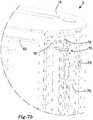
- Figs. 7a and 7billustrate insides of the dispenser 2 illustrated in Figs. 1 - 6 .
- a level indicator 70for indicating a level of sheets of web material in the reservoir 6 is shown.
- the level indicator 70is movable in a vertical direction, seen when the dispenser 2 is placed on a surface with its lid 10 facing upwardly.
- the level indicator 70is visible from an outside of the dispenser 2 through a peep hole 72.
- a surface 74 of the level indicator 70 facing the peep hole 72is differently coloured at its upper and lower portions. For instance, the upper portion of the surface 74 may be coloured green and the lower portion of the surface 74 may be coloured red.
- the green colouris visible through the peep hole 72 when the level indicator 70 is in a lower position, as illustrated in Fig. 7a
- the red colouris visible through the peep hole 72 when the level indicator 70 is in an upper position, as illustrated in Fig. 7b .
- the movable platform 60 in the cassette 16engages with the level indicator 70 when the movable platform 60 reaches an end portion of the housing 4 near the lid 10, and displaces the level indicator 70 from a first position to at least a second position, e.g. from the lower position to a position closer to the upper position.
- the level indicator 70In its lower position, the level indicator 70 is supported by a ledge 76 arranged on an inside of the housing 4.
- the movable platform 60is provided with a protuberance 78.
- the protuberance 78engages with the level indicator 70 when the movable platform 60 has been moved towards the lid 10 by the first biasing arrangement 14, as the stack of sheets of web material in the reservoir 6 decreases.
- Fig. 8illustrates a partial cross section through a dispenser 2 according to embodiments.
- the dispenser 2may comprise features as discussed in connection with the embodiments of Figs. 1 - 7b .
- a cassette 16 of the dispenser 2comprises a projection 80 on an outside of the cassette 16 and a housing 4 of the dispenser 2 is provided with a groove 82.
- the projection 80is arranged to slide in the groove 82 and along the groove 82 when the cassette 16 is moved along the housing 4.
- the cassette 16is guided by the projection 80 sliding along the groove 82.
- the projection 80is elastic and engages frictionally with the housing 4 in the groove 82.
- the housing 4comprises a protuberance 84 arranged in the groove 82 such that the projection 80 may releasably engaged with the protuberance 84 when the projection 80 is slid past the protuberance 84 in the groove 82.
- the cassette 16may be held in a specific position in the housing 4 by the engagement between the protuberance 84 and the projection 80.
- the engagement between the protuberance 84 and the projection 80may hold the cassette 16 in a position at least partially outside the housing 4 for refilling a reservoir 6 in the cassette 16 with sheets of web material, as illustrated in Fig. 8 .
- the dispenser 2may additionally comprise a securing arrangement 22 as discussed in connection with Fig. 6 .
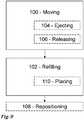
- Fig. 9illustrates embodiments of a method of refilling a dispenser with a stack of sheets of web material.
- the dispensermay be a dispenser 2 as disclosed herein. Accordingly, the method is further illustrated e.g. in Figs. 3 - 5 wherein different positions of a cassette 16 in a housing 4 of the dispenser 2 are disclosed.
- the dispenseris provided with a reservoir for the stack of sheets of web material and comprises the housing.
- the dispensercomprises a lid being provided with a dispensing opening for sheets of web material, wherein the lid is adapted to face upwardly during use of the dispenser.
- the dispensercomprises a first biasing arrangement for biasing the stack of sheets of web material towards the lid and the dispensing opening.
- the cassettecomprises the reservoir and is arranged to be moved to a position at least partially outside the housing, wherein the cassette is provided with a refill opening for sheets of web material, the refill opening being accessible when the cassette is in the position at least partially outside the housing.
- the dispensermay comprise a second biasing arrangement adapted to bias the cassette in a vertical direction towards the position at least partially outside the housing.
- the moving 100may comprise:
- the dispensermay comprise a securing arrangement for holding the cassette in place in the housing against a biasing force of the second biasing arrangement.
- the moving 100may comprise:
- the securing arrangement 22may comprise a push button 40, and the moving 100 may comprise engagement of the push button 40 to release the securing arrangement 22.
- the methodmay comprise:
- the dispensermay comprise a securing arrangement 22 for holding the cassette in place in a position at least partially outside the housing, and the repositioning 108 may comprise releasing the securing arrangement 22 to permit movement of the cassette towards the position in the housing.
- the securing arrangement 22may comprise a push button, and the repositioning may comprise engagement of the push button 40 to release the securing arrangement 22.
- the repositioning 108may comprise pushing the cassette towards the housing to release the securing arrangement 22 to permit movement of the cassette towards the position in the housing.
- the refilling 102may comprise:
- the housing 4may comprise two side elements, which are secured to each other, and a bottom portion attached to the side elements, e.g. by screws.
- the housing 4may comprise a sheet metal cladding.
- the sheet metal claddingmay extend around outer sides of the two side elements.
- the sheet metal claddingmay be attached to the side elements e.g. by means of glue or double-stick tape.
- the sheet metal claddingmay be provided with a slot to expose the peep hole 72.
Landscapes
- Engineering & Computer Science (AREA)
- Mechanical Engineering (AREA)
- Health & Medical Sciences (AREA)
- Public Health (AREA)
- Containers And Packaging Bodies Having A Special Means To Remove Contents (AREA)
- Automatic Analysis And Handling Materials Therefor (AREA)
- Refuse Receptacles (AREA)
- Treatment Of Fiber Materials (AREA)
- Details Of Rigid Or Semi-Rigid Containers (AREA)
Description
- The present invention relates to a dispenser for sheets of web material and to a method of refilling a dispenser.
US 2006/273102 discloses a dispenser including a body having four side walls, a base and an opening in a top of the body. A lid is hingedly connected near the top of the body and covers the opening. The lid has a slot therein for sheet material to be dispensed there through. The sheet material is forced by a compression element towards the lid. The lid is opened to refill the dispenser with a stack of sheet material. The forces of the compression element acting on the sheet material may affect the lid when the lid is to be closed after adding the stack of web material to the dispenser.- An object of the present invention is to provide a dispenser which is adapted for dispensing sheets of web material upwardly, wherein a refilling of the dispenser is uncomplicated.
- According to an aspect of the invention, the object is achieved by a dispenser according to
claim 1 provided with a reservoir for a stack of sheets of web material and comprising a housing. The dispenser comprises a lid being provided with a dispensing opening for sheets of web material. The lid is adapted to face upwardly during use of the dispenser. The dispenser comprises a first biasing arrangement for biasing the stack of sheets of web material towards the lid and the dispensing opening. The dispenser comprises a cassette, which cassette comprises the reservoir and is arranged to be moved to a position at least partially outside the housing, wherein the cassette is provided with a refill opening for sheets of web material, the refill opening being accessible when the cassette is in the position at least partially outside the housing. - Since the dispenser comprises the cassette comprising the reservoir, which cassette is provided with a refill opening for sheets of web material and the refill opening is accessible when the cassette is in the position at least partially outside the housing, a user may easily refill the dispenser with sheets of web material via the refill opening when the cassette is in the position at least partially outside the housing. As a result, the above mentioned object is achieved in the dispenser comprising a lid adapted to face upwardly during use of the dispenser.
- The dispenser may be a stand-alone unit adapted to be placed on a surface, such as a table, a worktop, or a dressing table. The dispenser may be adapted to be arranged with the stack of sheets of web material extending substantially vertically in the reservoir of the dispenser. That is, the sheets of web material may extend in substantially horizontal planes in the stack. A user may dispense sheets of web material substantially upwardly from the dispenser.
- The sheets of web material in the stack of sheets of web material may comprise a cellulose material. The web material may be a soft and absorbent sheet of web material, e.g. the sheets of web material may be sheets of web material for general wiping purposes. The sheets of web material may be towels or napkins. Accordingly, the dispenser may be arranged for dispensing sheets of web material for general wiping purposes, or the dispenser may be arranged for dispensing towels or for dispensing napkins. In a stack of sheets of web material adapted for placing in the reservoir of the dispenser, the sheets of web material may be folded sheets of web material which are interleaved. Thus, as each sheet of web material is dispensed from the dispenser, a portion of a following sheet of web material may be exposed for subsequent dispensing at the dispensing opening. Suitably the portion of the following sheet extends through the dispensing opening for grasping by a user.
- According to embodiments, the lid may be attached to, or may form part of, the cassette, and the dispensing opening and the refill opening may face in substantially perpendicular directions. In this manner the lid is movable together with the cassette and the refill opening is accessible for refilling the reservoir with sheets of web material from a lateral side of the dispenser.
- According to embodiments the refill opening may extend over substantially an entire length of the cassette and over substantially an entire width of the cassette. In this manner substantially an entire side of the cassette may form the refill opening. Thus, the reservoir may easily be accessed and the stack of sheets of web material in the reservoir may easily be refilled.
- According to the invention, the dispenser comprises a second biasing arrangement adapted to bias the cassette in a vertical direction towards the position at least partially outside the housing. In this manner an ejection of the cassette may be facilitated. At least a first movement of the cassette in relation to the housing thus, may be initiated by the second biasing arrangement.
- According to embodiments, the dispenser may comprise a securing arrangement for holding the cassette in place in the housing against a biasing force of the second biasing arrangement. In this manner the cassette may be held in the housing during use of the dispenser.
- According to embodiments, the securing arrangement may be releasable to permit movement of the cassette to the position at least partially outside the housing. According to embodiments, the securing arrangement may comprise a protruding element in the housing, and the protruding element may be arranged to project into a recess provided in the cassette. In this manner the protruding element may engage with the cassette in the recess to hold the cassette in place in the housing.
- According to embodiments, the protruding element may be biased in a direction towards the cassette. In this manner it may be ensured that the protruding element engages with the cassette when the cassette is positioned with the recess at the protruding element. According to embodiments, the securing arrangement may be further arranged to hold the cassette in the position at least partially outside the housing. In this manner the cassette may be held in the position at least partially outside the housing to facilitate access to the refill opening, e.g. for refilling the reservoir with sheets of web material. According to embodiments, the protruding element may comprise a slanted edge arranged to abut against an outer surface of the cassette. In this manner the protruding element may be moved away from the cassette to release the cassette, e.g. after refilling the reservoir, by applying a downward pressure to the lid. The cassette may then be returned to a position in the housing, for dispensing sheets of web material from the dispenser.
- According to embodiments, the securing arrangement may comprise a push button connected with the protruding element such that an engagement of the push button releases the protruding element from the recess. In this manner the securing arrangement, and accordingly the cassette, may be easily released by engaging the push button to permit movement of cassette to the position at least partially outside the housing. The push button may be directly or indirectly connected with the protruding element.
- According to embodiments, the push button may be accessible through the lid. In this manner the push button may be easily accessible for engagement at an upper side of the dispenser. The lid may be provided with a through hole, through which the push button is accessible.
- According to embodiments, the securing arrangement may comprise a third biasing arrangement for biasing the protruding element in the direction towards the cassette and for biasing the push button in a direction outwardly from the dispenser. In this manner it may be ensured that the protruding element engages with the recess while the push button is always returned to an outer position, from which outer position it may be engaged by a user desiring to access the reservoir, e.g. to refill the dispenser.
- According to embodiments, the cassette may comprise a projection on an outside of the cassette and the housing may be provided with a groove, wherein the projection may be arranged to slide in the groove and along the groove, when the cassette is moved along the housing. In this manner the cassette may be guided by the projection sliding in and along the groove to ensure that the cassette is not displaced from an intended travel path in the housing.
- According to embodiments, the projection may be elastic and may frictionally engage with the housing in the groove. In this manner movement of the cassette in the housing may be controlled, e.g. to restrict the effect the second biasing arrangement may have on the cassette. Put differently, the cassette may be less likely to abruptly pop out of the housing when the securing arrangement is released, but will instead slide in a controlled manner in the housing.
- According to embodiments, the housing may comprise a protuberance arranged in the groove such that the projection may be releasably engaged with the protuberance when the projection is slid past the protuberance in the groove. In this manner the cassette may be held in a specific position in the housing by the engagement between the protuberance and the projection.
- According to embodiments, the first biasing arrangement may be arranged in the cassette and may comprise a movable platform for supporting the stack of sheets of web material and a first resilient member abutting against the movable platform from a side opposite to the stack of sheets of web material. In this manner the stack may be biased towards the lid and the dispensing opening by the movable platform and the first resilient member.
- According to embodiments, the dispenser may comprise a level indicator for indicating a level of sheets of web material in the reservoir. In this manner service personnel may see whether the dispenser requires refilling without having to open the dispenser.
- According to embodiments, the movable platform may engage with the level indicator when the movable platform reaches an end portion of the housing near the lid, to displace the level indicator from a first position to at least a second position. In this manner the movable platform may affect the level indicator while it moves upwardly in the dispenser as sheets of web material are dispensed.
- According to embodiments, the second biasing arrangement may comprise a second resilient member arranged between the housing and the cassette at an end portion of the housing opposite to the lid.
- A further object of the present invention is to provide a method of refilling a dispenser with a stack of sheets of web material, wherein a refilling of the dispenser is uncomplicated and dispensing of sheets from the dispenser after refilling is easy.
- According to an aspect of the invention, the object is achieved by a method of refilling a dispenser with a stack of sheets of web material, according to
claim 16. The dispenser is provided with a reservoir for the stack of sheets of web material and comprises a housing. The dispenser comprises a lid being provided with a dispensing opening for sheets of web material, wherein the lid is adapted to face upwardly during use of the dispenser. The dispenser comprises a first biasing arrangement for biasing the stack of sheets of web material towards the lid and the dispensing opening. The dispenser further comprises a cassette, which cassette comprises the reservoir and is arranged to be moved to a position at least partially outside the housing, wherein the cassette is provided with a refill opening for sheets of web material, the refill opening being accessible when the cassette is in the position at least partially outside the housing. The lid, or a portion at an upper end of the cassette, forms an upper constraint of the reservoir. The method comprises: - moving the cassette upwardly into the position at least partially outside the housing, and
- refilling the reservoir with sheets of web material by placing a stack of sheets of web material through the refill opening into the reservoir within the formed upper constraint.
- Since the reservoir and the refill opening are easily accessible when the cassette is in the position at least partially outside the housing and the refilling is done within the upper constraint of the reservoir, the dispenser is prevented from being overfilled with sheets of web material. Thus, reliable dispensing of sheets of web material from a newly refilled dispenser may be ensured. As a result, the above mentioned object is achieved in the dispenser comprising a lid adapted to face upwardly during use of the dispenser.
- Further features of, and advantages with, the present invention will become apparent when studying the appended claims and the following detailed description. Those skilled in the art will realize that different features of the present invention may be combined to create embodiments other than those described in the following, without departing from the scope of the present invention, as defined by the appended claims.
- The various aspects of the invention, including its particular features and advantages, will be readily understood from the following detailed description and the accompanying drawings, in which:
Figs. 1 and 2 illustrate a dispenser according to embodiments,Figs. 3 - 5 illustrate cross sections through the dispenser illustrated inFigs. 1 and 2 ,Fig. 6 illustrates embodiments of a securing arrangement of a dispenser,Figs. 7a and7b illustrate insides of the dispenser illustrated inFigs. 1 - 6 , andFig. 8 illustrates a partial cross section through a dispenser according to embodiments.- The present invention will now be described more fully with reference to the accompanying drawings, in which example embodiments are shown. However, this invention should not be construed as limited to the embodiments set forth herein. Disclosed features of example embodiments may be combined as readily understood by one of ordinary skill in the art to which this invention belongs. Like numbers refer to like elements throughout. Well-known functions or constructions will not necessarily be described in detail for brevity and/or clarity.
Figs. 1 and 2 illustrate adispenser 2 according to embodiments. Thedispenser 2 is provided with areservoir 6 for a stack of sheets of web material. Thedispenser 2 comprises ahousing 4. Thedispenser 2 comprises alid 10 being provided with a dispensingopening 12 for sheets of web material. Thelid 10 faces upwardly during use of thedispenser 2. Accordingly, a side of thedispenser 2 opposite to thelid 10 is adapted to form a supporting side of thedispenser 2, which supporting side is arranged to face a supporting surface upon which thedispenser 2 is placed. The supporting side of thedispenser 2 may be provided with one or more friction elements, such as rubber feet or pads of other types. A friction element may comprise a tacky elastomeric composition arranged for releasable and reusable securing of thedispenser 2 to a supporting surface. Accordingly, thedispenser 2 forms a stand-alone unit. Thedispenser 2 comprises acassette 16. Thecassette 16 comprises thereservoir 6 for the stack of sheets of web material. Thecassette 16 is movable in thehousing 4. Thecassette 16 is arranged to be moved to a position at least partially outside thehousing 4.- In
Fig. 1 thedispenser 2 is illustrated with thecassette 16 positioned inside thehousing 4. InFig. 2 thedispenser 2 is illustrated with thecassette 16 in and upper end position, in which upper end position thecassette 16 is partially outside thehousing 4. Thecassette 16 may be arranged in thehousing 4 in such a manner that thecassette 16 cannot be removed from thehousing 4 without disassembling thehousing 4. In the upper end position, thecassette 16 may be refilled with sheets of web material. - The
cassette 16 is provided with arefill opening 18 for sheets of web material. Therefill opening 18 is accessible when thecassette 16 is in the position at least partially outside thehousing 4. A user may thus, easily refill thedispenser 2 with sheets of web material via therefill opening 18 when the cassette is in the position at least partially outside the housing. - The
lid 10 is attached to, or forms part of, thecassette 16. The dispensingopening 12 and therefill opening 18 face in substantially perpendicular directions. That is, the dispensingopening 12 faces upwardly and the refill opening 18 faces laterally when thedispenser 2 is placed upon a supporting surface. When thecassette 16 is positioned in the position at least partially outside thehousing 4, therefill opening 18 is accessible for refilling thereservoir 6 with sheets of web material. A stack of sheets of web material is easily placed in thereservoir 6. Therefill opening 18 extends over substantially an entire length of thecassette 16 and over substantially an entire width of thecassette 16. - The
lid 10, or a portion at an upper end of thecassette 16, forms an upper constraint of thereservoir 6. Thus, when thedispenser 2 is refilled with sheets of web material, thedispenser 2 is prevented from being overfilled by this constraint. Reliable dispensing of sheets of web material from a newly filleddispenser 2 thus, may be ensured. Conversely, a prior art dispenser, which is refilled through an upper opening beneath a lid provided with a dispensing opening, may risk overfilling. This requires the lid to be forced back onto the housing. Dispensing of the first sheets from an overfilled dispenser of this prior art kind may be difficult. Figs. 3 - 5 illustrate cross sections through thedispenser 2 illustrated inFigs. 1 and 2 . InFig. 3 thedispenser 2 is illustrated with thecassette 16 in a lower end position in thehousing 4. Thecassette 16 is secured in the housing in this lower end position. In thereservoir 6 of thedispenser 2, astack 8 of sheets of web material is arranged. Sheets of web material may be dispensed through the dispensingopening 12 in thelid 10.- In
Fig. 4 thedispenser 2 is illustrated with a portion of thecassette 16 outside thehousing 4. Thereservoir 6 of thedispenser 2 is empty and thus, in need of refilling. - The
dispenser 2 comprises afirst biasing arrangement 14 for biasing a stack of sheets of web material in thereservoir 6 towards thelid 10 and the dispensingopening 12. Thefirst biasing arrangement 14 is arranged in thecassette 16 and comprises amovable platform 60 for supporting a stack of sheets of web material and a firstresilient member 62 abutting against themovable platform 60 from a side opposite to the stack of sheets of web material. In these embodiments the firstresilient member 62 comprises a spring arranged between abottom element 63 of thecassette 16 and themovable platform 60. Since thereservoir 6 is empty, theplatform 60 is biased into a position at an upper end of thehousing 4. - Provided purely as an example; the
reservoir 6 may house a stack of sheets of web material having a height of 10 - 20 cm, or approximately 15 cm. The sheets of web material may have a width of 10 - 30 cm, or approximately 24 cm and a breadth of 6 - 15 cm, or approximately 9 cm, in a folded state as provided in thedispenser 2. Thefirst biasing arrangement 14 may provide a biasing force of 10 - 12 N when thefirst biasing arrangement 14 is fully compressed, i.e. when theplatform 60 is in a bottom position in thecassette 16. - The
dispenser 2 comprises asecond biasing arrangement 20 adapted to bias thecassette 16 in a vertical direction towards the position at least partially outside thehousing 4. As illustrated inFig. 4 , thesecond biasing arrangement 20 has moved a portion of thecassette 16 outside thehousing 4. Thecassette 16 may be manually moved further outside thehousing 4 from the position illustrated inFig. 4 , to an upper end position. Due to thesecond biasing arrangement 20, thecassette 16 is partially ejected from thehousing 4 upon release of a securingarrangement 22, which will be elaborated on further below. Thesecond biasing arrangement 20 comprises a secondresilient member 73 arranged between thehousing 4 and thecassette 16 at anend portion 74 of thehousing 4 opposite to thelid 10. More specifically, the secondresilient member 73 may comprise a spring. In these embodiments thesecond biasing arrangement 20 comprises two springs. Provided purely as an example; thesecond biasing arrangement 20 may provide a biasing force of approximately 15 N when thesecond biasing arrangement 20 is fully compressed, i.e. when thecassette 16 is in the lower position in thehousing 4, as illustrated inFig. 3 . - In
Fig. 5 thedispenser 2 is illustrated with thecassette 16 in an upper end position. In the upper end position thereservoir 6 may be refilled with sheets of web material. Thecassette 16 may be held in the position at least partially outside thehousing 4 by a securingarrangement 22, which will be elaborated on further below. - The
platform 60 is in the position at the upper end of thehousing 4. In the upper end position of thecassette 16, themovable platform 60 and thebottom element 63 of thecassette 16 are close to each other. The firstresilient member 62 is compressed. Thus, the entire refill opening 18 in thecassette 16 is accessible to a user who is about to refill thedispenser 2. Fig. 6 illustrates embodiments of a securingarrangement 22 of thedispenser 2 illustrated inFigs. 1 - 5 . The securingarrangement 22 is arranged for holding thecassette 16 in place in thehousing 4 against the biasing force of thesecond biasing arrangement 20. A corresponding securing arrangement is provided at an opposite side of thedispenser 2.- The securing
arrangement 22 is releasable to permit movement of thecassette 16 to the position at least partially outside thehousing 4. When the securing arrangement is released, thecassette 16 is partially ejected from thehousing 4 by thesecond biasing arrangement 20 to a position as illustrated inFig. 4 . From this position a user may move thecassette 16 to the upper end position of thecassette 16, as illustrated inFig. 5 . - The securing
arrangement 22 is mainly arranged in thehousing 4 and comprises a protrudingelement 30, alink member 46, athird biasing arrangement 44, and apush button 40. Thelid 10 is provided with a through hole. Thepush button 40 is accessible through thelid 10. More specifically, thepush button 40 is accessible through the through hole of thelid 10. Thelid 10 is connected with thecassette 16 and thus, movable together with thecassette 16. Thelink member 46 is rotatable about anaxis 47 and comprises afirst projection 48 and asecond projection 49. Thefirst projection 48 engages with the protrudingelement 30. More specifically, thefirst projection 48 extends into anaperture 50 of the protrudingelement 30. Thepush button 40 abuts against thesecond projection 49. Thethird biasing arrangement 44 comprises a torsional spring wound about theaxis 47. The torsional spring abuts at one end against thelink member 46 and at an opposite end against thepush button 40. Thus, thethird biasing arrangement 44 biases thepush button 40 against aseat 52 in thehousing 4 and the protrudingelement 30, via thefirst projection 48, towards thecassette 16. Thus, thepush button 40 is biased in a direction outwardly from thedispenser 2 to an outer position. From the outer position thepush button 40 may be engaged by a user desiring to access thereservoir 6. - The protruding
element 30 is arranged to project into a recess 32 provided in thecassette 16. Thus, the protrudingelement 30 engages with thecassette 16 in the recess 32 and holds thecassette 16 in place in thehousing 4, against the biasing force of thesecond biasing arrangement 20. Since the protrudingelement 30 is biased in a direction towards thecassette 16 it is ensured that the protrudingelement 30 will engage with thecassette 16 and the recess 32 therein. - Moreover, the securing
arrangement 22 is arranged to hold thecassette 16 in the position at least partially outside thehousing 4. This is achieved by the protrudingelement 30 extending underneath thecassette 16 when thecassette 16 is in its upper end position, as illustrated inFig. 5 . Again, the biasing of the protrudingelement 30 towards thecassette 16 ensures that the protrudingelement 30 will be positioned underneath thecassette 16. The protrudingelement 30 comprises a slantededge 34 arranged to abut against an outer surface of thecassette 16. Thus, a bottom of thecassette 16 resting against the slantededge 34 of the protrudingelement 30 may force the protrudingelement 30, against thethird biasing arrangement 44, away from thecassette 16 when a downward pressure is applied to thelid 10 of thedispenser 2. When, upon repositioning thecassette 16 in thehousing 4, thecassette 16 reaches the position illustrated inFig. 4 , a user may push on thelid 10 to return thecassette 16 to the lower end position in thehousing 4, in which lower end position thethird biasing arrangement 44 will bias the protrudingelement 30 into the recess 32 in thecassette 16. - When the
cassette 16 is in its lower end position, as illustrated inFig. 3 , and since thepush button 40 is connected to the protrudingelement 30 via thelink member 46 and its first andsecond projections push button 40 releases the protrudingelement 30 from the recess 32, and thecassette 16 is ejected by thesecond biasing arrangement 20 to the position illustrated inFig. 4 .The engagement of thepush button 40 in these embodiments comprises pushing thepush button 40 downwardly. - When the
cassette 16 is in its upper end position, as illustrated inFig. 4 , engagement of thepush button 40 results in release of the securingarrangement 22, such thatcassette 16 may be moved downwardly to the position illustrated inFig. 4 . From this position, a user may push on thelid 10 to return thecassette 16 to the lower end position, as illustrated inFig. 3 . - Alternatively, when the
cassette 16 is in its upper end position, as illustrated inFig. 4 , a user may push on thelid 10 whereby the securingarrangement 22 is released, and thecassette 16 may be moved downwardly to the position illustrated inFig. 4 . From this position, a user may continue pushing on thelid 10 so as to return thecassette 16 to the lower end position, as illustrated inFig. 3 . Figs. 7a and7b illustrate insides of thedispenser 2 illustrated inFigs. 1 - 6 . InFigs. 7a and7b alevel indicator 70 for indicating a level of sheets of web material in thereservoir 6 is shown. Thelevel indicator 70 is movable in a vertical direction, seen when thedispenser 2 is placed on a surface with itslid 10 facing upwardly. Thelevel indicator 70 is visible from an outside of thedispenser 2 through apeep hole 72. Asurface 74 of thelevel indicator 70 facing thepeep hole 72 is differently coloured at its upper and lower portions. For instance, the upper portion of thesurface 74 may be coloured green and the lower portion of thesurface 74 may be coloured red. Thus, the green colour is visible through thepeep hole 72 when thelevel indicator 70 is in a lower position, as illustrated inFig. 7a , and the red colour is visible through thepeep hole 72 when thelevel indicator 70 is in an upper position, as illustrated inFig. 7b .- The
movable platform 60 in thecassette 16 engages with thelevel indicator 70 when themovable platform 60 reaches an end portion of thehousing 4 near thelid 10, and displaces thelevel indicator 70 from a first position to at least a second position, e.g. from the lower position to a position closer to the upper position. - In its lower position, the
level indicator 70 is supported by aledge 76 arranged on an inside of thehousing 4. Themovable platform 60 is provided with aprotuberance 78. Theprotuberance 78 engages with thelevel indicator 70 when themovable platform 60 has been moved towards thelid 10 by thefirst biasing arrangement 14, as the stack of sheets of web material in thereservoir 6 decreases. Fig. 8 illustrates a partial cross section through adispenser 2 according to embodiments. Thedispenser 2 may comprise features as discussed in connection with the embodiments ofFigs. 1 - 7b . Acassette 16 of thedispenser 2 comprises aprojection 80 on an outside of thecassette 16 and ahousing 4 of thedispenser 2 is provided with agroove 82. Theprojection 80 is arranged to slide in thegroove 82 and along thegroove 82 when thecassette 16 is moved along thehousing 4. Thus, thecassette 16 is guided by theprojection 80 sliding along thegroove 82. Theprojection 80 is elastic and engages frictionally with thehousing 4 in thegroove 82.- The
housing 4 comprises aprotuberance 84 arranged in thegroove 82 such that theprojection 80 may releasably engaged with theprotuberance 84 when theprojection 80 is slid past theprotuberance 84 in thegroove 82. Thus, thecassette 16 may be held in a specific position in thehousing 4 by the engagement between theprotuberance 84 and theprojection 80. For instance, the engagement between theprotuberance 84 and theprojection 80 may hold thecassette 16 in a position at least partially outside thehousing 4 for refilling areservoir 6 in thecassette 16 with sheets of web material, as illustrated inFig. 8 . Thedispenser 2 may additionally comprise a securingarrangement 22 as discussed in connection withFig. 6 . Fig. 9 illustrates embodiments of a method of refilling a dispenser with a stack of sheets of web material. The dispenser may be adispenser 2 as disclosed herein. Accordingly, the method is further illustrated e.g. inFigs. 3 - 5 wherein different positions of acassette 16 in ahousing 4 of thedispenser 2 are disclosed. The dispenser is provided with a reservoir for the stack of sheets of web material and comprises the housing. The dispenser comprises a lid being provided with a dispensing opening for sheets of web material, wherein the lid is adapted to face upwardly during use of the dispenser. The dispenser comprises a first biasing arrangement for biasing the stack of sheets of web material towards the lid and the dispensing opening. The cassette comprises the reservoir and is arranged to be moved to a position at least partially outside the housing, wherein the cassette is provided with a refill opening for sheets of web material, the refill opening being accessible when the cassette is in the position at least partially outside the housing. The lid, or a portion at an upper end of the cassette, forms an upper constraint of the reservoir. The method comprises:- moving 100 the cassette upwardly into the position at least partially outside the housing, and
- refilling 102 the reservoir with sheets of web material by placing a stack of sheets of web material through the refill opening into the reservoir within the formed upper constraint.
- According to embodiments, the dispenser may comprise a second biasing arrangement adapted to bias the cassette in a vertical direction towards the position at least partially outside the housing. The moving 100 may comprise:
- ejecting 104 the cassette from the housing by the second biasing arrangement towards the position at least partially outside the housing. In this manner a partial movement towards the position at least partially outside the housing may be achieved by the second biasing arrangement. A full movement to the position at least partially outside the housing, in which the dispenser may be refilled, may be achieved by a user moving the cassette form the ejected position to the position at least partially outside the housing.
- According to embodiments, the dispenser may comprise a securing arrangement for holding the cassette in place in the housing against a biasing force of the second biasing arrangement. The moving 100 may comprise:
- releasing 106 the securing arrangement to permit movement of the cassette to the position at least partially outside the housing. In this manner the cassette may not be ejected from the housing by the second biasing arrangement towards the position at least partially outside the housing until the releasing 106 the securing arrangement.
- According to embodiments, the securing
arrangement 22 may comprise apush button 40, and the moving 100 may comprise engagement of thepush button 40 to release the securingarrangement 22. - According to embodiments, the method may comprise:
- repositioning 108 the cassette in the housing. In this manner the cassette may be returned into the housing after refilling the reservoir with a stack of sheets of web material and sheets of web material may be dispensed from the dispenser through its dispensing opening.
- According to embodiments, the dispenser may comprise a securing
arrangement 22 for holding the cassette in place in a position at least partially outside the housing, and therepositioning 108 may comprise releasing the securingarrangement 22 to permit movement of the cassette towards the position in the housing. - According to embodiments, the securing
arrangement 22 may comprise a push button, and the repositioning may comprise engagement of thepush button 40 to release the securingarrangement 22. - According to alternative embodiments, the repositioning 108 may comprise pushing the cassette towards the housing to release the securing
arrangement 22 to permit movement of the cassette towards the position in the housing. - According to embodiments, the refilling 102 may comprise:
- placing 110 a stack having a height of 10 - 20 cm in the reservoir.
- Example embodiments described above may be combined as understood by a person skilled in the art. The
housing 4 may comprise two side elements, which are secured to each other, and a bottom portion attached to the side elements, e.g. by screws. Thehousing 4 may comprise a sheet metal cladding. The sheet metal cladding may extend around outer sides of the two side elements. The sheet metal cladding may be attached to the side elements e.g. by means of glue or double-stick tape. At thepeep hole 72, the sheet metal cladding may be provided with a slot to expose thepeep hole 72. Although the invention has been described with reference to example embodiments, many different alterations, modifications and the like will become apparent for those skilled in the art. Therefore, it is to be understood that the foregoing is illustrative of various example embodiments and that the invention is defined only the appended claims. - As used herein, the term "comprising" or "comprises" is open-ended, and includes one or more stated features, elements, steps, components or functions but does not preclude the presence or addition of one or more other features, elements, steps, components, functions or groups thereof.
Claims (16)
- A dispenser (2) provided with a reservoir (6) for a stack (8) of sheets of web material and comprising a housing (4), wherein the dispenser (2) comprises a lid (10) being provided with a dispensing opening (12) for sheets of web material, wherein the lid (10) is adapted to face upwardly during use of the dispenser (2), and wherein the dispenser (2) comprises a first biasing arrangement (14) for biasing the stack (8) of sheets of web material towards the lid (10) and the dispensing opening (12),characterized in that the dispenser (2) comprises a cassette (16), which cassette (16) comprises the reservoir (6) and is arranged to be moved to a position at least partially outside the housing (4), wherein the cassette (16) is provided with a refill opening (18) for sheets of web material, the refill opening (18) being accessible when the cassette (16) is in the position at least partially outside the housing (4), and wherein the dispenser (2) comprises a second biasing arrangement (20) adapted to bias the cassette (16) in a vertical direction towards the position at least partially outside the housing (4).
- The dispenser (2) according to claim 1, wherein the lid (10) is attached to, or forms part of, the cassette (16), and wherein the dispensing opening (12) and the refill opening (18) face in substantially perpendicular directions.
- The dispenser (2) according to claim 1 or 2, wherein the refill opening (18) extends over substantially an entire length of the cassette (16) and over substantially an entire width of the cassette (16).
- The dispenser (2) according to any one of the preceding claims, wherein the dispenser (2) comprises a securing arrangement (22) for holding the cassette (16) in place in the housing (4) against a biasing force of the second biasing arrangement (20),
wherein the securing arrangement (22) is preferably releasable to permit movement of the cassette (16) to the position at least partially outside the housing (4). - The dispenser (2) according to claim 4 , wherein the securing arrangement (22) comprises a protruding element (30) in the housing (4), the protruding element (30) being arranged to project into a recess (32) provided in the cassette (16),
wherein the protruding element (30) is preferably biased in a direction towards the cassette (16). - The dispenser (2) according to any one of claims -4-5, wherein the securing arrangement (22) is further arranged to hold the cassette (16) in the position at least partially outside the housing (4).
- The dispenser (2) according to claim 5 or claim 5 and 6,, wherein the protruding element (30) comprises a slanted edge (34) arranged to abut against an outer surface of the cassette (16).
- The dispenser (2) according to claim 5,claim 7 or claim 6 when dependent on claim 5, , wherein the securing arrangement (22) comprises a push button (40) connected with the protruding element (30) such that an engagement of the push button (40) releases the protruding element (30) from the recess, preferably the push button (40) is accessible through the lid (10).
- The dispenser (2) according to claim 8, wherein the securing arrangement (22) comprises a third biasing arrangement (44) for biasing the protruding element (30) in the direction towards the cassette (16) and for biasing the push button (40) in a direction outwardly from the dispenser (2).
- The dispenser (2) according to any one of the preceding claims, wherein the cassette (16) comprises a projection (80) on an outside of the cassette (16) and the housing (4) is provided with a groove (82), and wherein the projection (80) is arranged to slide in the groove (82) and along the groove (82), when the cassette (16) is moved along the housing (4).
- The dispenser (2) according to claim 10, wherein the projection (80) is elastic and frictionally engages with the housing (4) in the groove (82),
wherein the housing (4) preferably comprises a protuberance (84) arranged in the groove (82) such that the projection (80) is releasably engaged with the protuberance (84) when the projection (80) is slid past the protuberance (84) in the groove (82). - The dispenser (2) according to any one of the preceding claims, wherein the first biasing arrangement (14) is arranged in the cassette (16) and comprises a movable platform (60) for supporting the stack (8) of sheets of web material and a first resilient member (62) abutting against the movable platform (60) from a side opposite to the stack (8) of sheets of web material.
- The dispenser (2) according to any one of the preceding claims, wherein the dispenser (2) comprises a level indicator (70) for indicating a level of sheets of web material in the reservoir (6).
- The dispenser (2) according to claims 12 and 13, wherein the movable platform (60) engages with the level indicator (70) when the movable platform (60) reaches an end portion of the housing (4) near the lid (10), to displace the level indicator (70) from a first position to at least a second position.
- The dispenser (2) according to any one of the preceding claims,, wherein the second biasing arrangement (20) comprises a second resilient member (73) arranged between the housing (4) and the cassette (16) at an end portion of the housing (4) opposite to the lid (10).
- A method of refilling a dispenser (2) with a stack (8) of sheets of web material, the dispenser (2) being provided with a reservoir (6) for the stack of sheets of web material and comprising a housing (4), wherein the dispenser (2) comprises a lid (10) being provided with a dispensing opening (12) for sheets of web material, wherein the lid (10) is adapted to face upwardly during use of the dispenser (2), and wherein the dispenser (2) comprises a first biasing arrangement (14) for biasing the stack (8) of sheets of web material towards the lid (10) and the dispensing opening (12), the dispenser (2) further comprising a cassette (16), which cassette (16) comprises the reservoir (6) and is arranged to be moved to a position at least partially outside the housing (4), wherein the cassette (16) is provided with a refill opening (18) for sheets of web material, the refill opening (18) being accessible when the cassette (16) is in the position at least partially outside the housing (4), wherein the lid (10), or a portion at an upper end of the cassette (16), forms an upper constraint of the reservoir (6), and wherein the dispenser (2) comprises a second biasing arrangement (20) adapted to bias the cassette (16) in a vertical direction towards the position at least partially outside the housing (4), the method comprising:- moving (100) the cassette (16) upwardly into the position at least partially outside the housing (4), wherein the moving (100) comprises ejecting (104) the cassette (16) from the housing (4) by the second biasing arrangement (20) towards the position at least partially outside the housing (4),- refilling (102) the reservoir (6) with sheets of web material by placing a stack (8) of sheets of web material through the refill opening (18) into the reservoir (6) within the formed upper constraint.
Priority Applications (1)
| Application Number | Priority Date | Filing Date | Title |
|---|---|---|---|
| PL13884430TPL2996530T3 (en) | 2013-05-17 | 2013-05-17 | Dispenser and method of refilling dispenser |
Applications Claiming Priority (1)
| Application Number | Priority Date | Filing Date | Title |
|---|---|---|---|
| PCT/SE2013/050558WO2014185842A1 (en) | 2013-05-17 | 2013-05-17 | Dispenser and method of refilling dispenser |
Publications (3)
| Publication Number | Publication Date |
|---|---|
| EP2996530A1 EP2996530A1 (en) | 2016-03-23 |
| EP2996530A4 EP2996530A4 (en) | 2017-01-18 |
| EP2996530B1true EP2996530B1 (en) | 2019-05-08 |
Family
ID=51898686
Family Applications (1)
| Application Number | Title | Priority Date | Filing Date |
|---|---|---|---|
| EP13884430.3ANot-in-forceEP2996530B1 (en) | 2013-05-17 | 2013-05-17 | Dispenser and method of refilling dispenser |
Country Status (12)
| Country | Link |
|---|---|
| US (3) | US20160088982A1 (en) |
| EP (1) | EP2996530B1 (en) |
| CN (1) | CN105208904B (en) |
| AU (1) | AU2013389392B2 (en) |
| BR (1) | BR112015028872A2 (en) |
| CA (1) | CA2912370A1 (en) |
| DK (1) | DK2996530T3 (en) |
| ES (1) | ES2729577T3 (en) |
| MX (1) | MX364921B (en) |
| PL (1) | PL2996530T3 (en) |
| RU (1) | RU2625730C2 (en) |
| WO (1) | WO2014185842A1 (en) |
Families Citing this family (13)
| Publication number | Priority date | Publication date | Assignee | Title |
|---|---|---|---|---|
| FR2907654B1 (en) | 2006-10-31 | 2010-01-29 | Georgia Pacific France | PROCESS, MANUFACTURING DEVICE AND ASSOCIATED ROLLS FORMED OF CUTTING SHEETS AND ALTERNATE PREDECOUPLES |
| US11297984B2 (en) | 2006-10-31 | 2022-04-12 | Gpcp Ip Holdings Llc | Automatic napkin dispenser |
| US10383489B2 (en)* | 2012-02-10 | 2019-08-20 | Gpcp Ip Holdings Llc | Automatic napkin dispenser |
| US9604811B2 (en) | 2013-10-01 | 2017-03-28 | Georgia-Pacific Consumer Products Lp | Automatic paper product dispenser with data collection and method |
| RU2641946C2 (en)* | 2013-12-09 | 2018-01-23 | Ска Хайджин Продактс Аб | Dispenser for napkins nested in each other |
| CA3044547A1 (en)* | 2017-01-09 | 2018-07-12 | Essity Hygiene And Health Aktiebolag | Dispenser for dispensing sheet products |
| WO2018209110A1 (en) | 2017-05-10 | 2018-11-15 | Gpcp Ip Holdings Llc | Automatic paper product dispenser and associated methods |
| PL4044890T3 (en)* | 2019-10-15 | 2024-04-29 | Sofidel S.P.A. | A dispenser for cellulose products in sheet form |
| US11116365B2 (en) | 2019-12-18 | 2021-09-14 | Essity Hygiene And Health Aktiebolag | Horizontally oriented paper product dispenser and related methods |
| US10980377B1 (en) | 2019-12-18 | 2021-04-20 | Essity Hygiene And Health Aktiebolag | Apparatus and methods for paper dispensing |
| US11641986B2 (en)* | 2020-12-01 | 2023-05-09 | Cintas Corporate Services, Inc. | Multi-orientation towel dispenser |
| US20230320470A1 (en)* | 2022-04-12 | 2023-10-12 | Jeff King Hair, LLC | Holder and Dispenser for Folded Hair Treatment Materials |
| USD1025645S1 (en)* | 2023-04-05 | 2024-05-07 | Stephanie Todd | Liner dispenser |
Family Cites Families (40)
| Publication number | Priority date | Publication date | Assignee | Title |
|---|---|---|---|---|
| US2277815A (en)* | 1939-07-05 | 1942-03-31 | Marathon Paper Mills Co | Dispenser |
| US2435104A (en)* | 1946-01-09 | 1948-01-27 | Joseph H Solomon | Napkin holder |
| NL73002C (en)* | 1948-10-28 | |||
| US3106314A (en)* | 1961-12-20 | 1963-10-08 | Rufus P Spears | Advertising napkin holder |
| US3214227A (en)* | 1964-07-09 | 1965-10-26 | American Can Co | Dispenser |
| US3343716A (en)* | 1966-03-22 | 1967-09-26 | Peebles David Meade | Dispensers for facial tissues and the like |
| US3826406A (en)* | 1970-05-25 | 1974-07-30 | V Moniot | Article dispenser |
| CA1098874A (en)* | 1980-02-07 | 1981-04-07 | Frank Richardson | Serviette dispenser |
| NL8102986A (en)* | 1981-06-19 | 1983-01-17 | Avedko Bv | DEVICE FOR STACKING OBJECTS. |
| US4694973A (en)* | 1985-12-02 | 1987-09-22 | Warmwipes, Inc. | Warming device for disposable towel dispenser |
| US4838454A (en)* | 1987-11-02 | 1989-06-13 | Traex Corporation | Napkin dispenser |
| USD361432S (en)* | 1993-11-12 | 1995-08-22 | Giovanni Lotti | Container, dispenser for ear cleaning sticks |
| US5678728A (en)* | 1995-06-22 | 1997-10-21 | Leto; Maria | Dispenser for flexible sheets |
| US6062421A (en)* | 1998-01-23 | 2000-05-16 | Marley; Jo Ellen | Glove dispensing device |
| AU136029S (en)* | 1998-04-09 | 1998-12-15 | Mt Cup Corp Pty Ltd | A box |
| EP1084670B1 (en)* | 1999-09-14 | 2005-11-09 | Combi Corporation | Wet tissue warmer and tissue lifting plate |
| US20020162849A1 (en) | 2001-05-04 | 2002-11-07 | Chen Fang Yeh | Structure art design knife blade container |
| GB0124867D0 (en)* | 2001-10-17 | 2001-12-05 | Ncr Int Inc | Media cassette |
| US7093737B2 (en)* | 2003-04-16 | 2006-08-22 | Kimberly-Clark Worldwide, Inc. | Container and cartridge for dispensing paper products |
| US7048143B2 (en)* | 2003-04-16 | 2006-05-23 | Kimberly-Clark Worldwide, Inc. | Container and cartridge for dispensing paper products |
| USD482915S1 (en)* | 2003-06-02 | 2003-12-02 | Simplehuman Llc | Plastic bag dispenser |
| US6981610B2 (en)* | 2004-03-10 | 2006-01-03 | Traex Company | Dispenser for a paper product |
| EP1755430B1 (en) | 2004-05-07 | 2010-04-21 | SCA Hygiene Products AB | A dispenser for individual folded webs |
| EP1742556A1 (en)* | 2004-05-07 | 2007-01-17 | Sca Hygiene Products Ab | Apparatus for serially dispensing folded sheet products |
| US7490733B2 (en)* | 2005-01-19 | 2009-02-17 | Daria Tagliareni | Dispenser assembly |
| US7726515B2 (en)* | 2005-04-29 | 2010-06-01 | Kimberly-Clark Worldwide, Inc. | Decorative and disposable bath tissue dispenser |
| EP2338398B1 (en)* | 2005-06-03 | 2016-06-08 | Sca Tissue North America Llc | Table top folded sheet dispenser |
| USD524084S1 (en) | 2005-06-03 | 2006-07-04 | Sca Hygiene Products Ab | Table top dispenser for folded absorbent sheet products |
| US20060273101A1 (en)* | 2005-06-07 | 2006-12-07 | Kimberly-Clark Worldwide, Inc. | Container and cartridge for dispensing paper products |
| US20070181594A1 (en)* | 2005-11-23 | 2007-08-09 | Thompson Mark C | Wall dispenser for rolled toilet paper and moistened wipes |
| CN101652296B (en)* | 2006-12-19 | 2011-12-21 | 艾杜亚特·夏斯 | Refillable tablet dispenser, tablet package and dispensing method |
| US20130164729A1 (en)* | 2008-01-28 | 2013-06-27 | Jill S. Rappa | Educational device and kit therefore |
| US20090191518A1 (en)* | 2008-01-28 | 2009-07-30 | Jill Rappa | Educational device and system therefore |
| US8631968B2 (en)* | 2011-06-04 | 2014-01-21 | Tony A. Taylor | Tissue advancement device for tissue boxes |
| US8863984B2 (en)* | 2011-08-30 | 2014-10-21 | Sca Hygiene Products Ab | Product dispenser and cover member for a product dispenser |
| CN202505244U (en)* | 2012-02-14 | 2012-10-31 | 陈剑峰 | Paper towel box with paper towel board capable of being automatically supported |
| CN202859006U (en)* | 2012-08-21 | 2013-04-10 | 李修志 | Convenience paper sheet pulling carton |
| US9125532B2 (en)* | 2012-12-20 | 2015-09-08 | Kimberly-Clark Worldwide, Inc. | Storing and dispensing container for wipes |
| US9230388B2 (en)* | 2013-03-14 | 2016-01-05 | Nice-Pak Products, Inc. | Flow wrap holder |
| WO2017023648A1 (en)* | 2015-08-05 | 2017-02-09 | Wausau Paper Towel & Tissue, Llc | Interfolded sheet dispenser |
- 2013
- 2013-05-17RURU2015153826Apatent/RU2625730C2/ennot_activeIP Right Cessation
- 2013-05-17DKDK13884430.3Tpatent/DK2996530T3/enactive
- 2013-05-17PLPL13884430Tpatent/PL2996530T3/enunknown
- 2013-05-17AUAU2013389392Apatent/AU2013389392B2/ennot_activeCeased
- 2013-05-17BRBR112015028872Apatent/BR112015028872A2/ennot_activeIP Right Cessation
- 2013-05-17EPEP13884430.3Apatent/EP2996530B1/ennot_activeNot-in-force
- 2013-05-17MXMX2015015557Apatent/MX364921B/enactiveIP Right Grant
- 2013-05-17ESES13884430Tpatent/ES2729577T3/enactiveActive
- 2013-05-17WOPCT/SE2013/050558patent/WO2014185842A1/enactiveApplication Filing
- 2013-05-17CNCN201380076550.5Apatent/CN105208904B/ennot_activeExpired - Fee Related
- 2013-05-17CACA2912370Apatent/CA2912370A1/ennot_activeAbandoned
- 2013-05-17USUS14/891,367patent/US20160088982A1/ennot_activeAbandoned
- 2018
- 2018-12-04USUS29/672,272patent/USD903366S1/enactiveActive
- 2018-12-04USUS29/672,270patent/USD903365S1/enactiveActive
Non-Patent Citations (1)
| Title |
|---|
| None* |
Also Published As
| Publication number | Publication date |
|---|---|
| USD903366S1 (en) | 2020-12-01 |
| RU2625730C2 (en) | 2017-07-18 |
| AU2013389392B2 (en) | 2016-03-03 |
| EP2996530A4 (en) | 2017-01-18 |
| MX2015015557A (en) | 2016-02-05 |
| MX364921B (en) | 2019-05-14 |
| CN105208904B (en) | 2018-09-14 |
| CN105208904A (en) | 2015-12-30 |
| DK2996530T3 (en) | 2019-06-11 |
| ES2729577T3 (en) | 2019-11-04 |
| EP2996530A1 (en) | 2016-03-23 |
| PL2996530T3 (en) | 2019-08-30 |
| CA2912370A1 (en) | 2014-11-20 |
| BR112015028872A2 (en) | 2017-07-25 |
| AU2013389392A1 (en) | 2015-11-26 |
| RU2015153826A (en) | 2017-06-22 |
| WO2014185842A1 (en) | 2014-11-20 |
| US20160088982A1 (en) | 2016-03-31 |
| USD903365S1 (en) | 2020-12-01 |
Similar Documents
| Publication | Publication Date | Title |
|---|---|---|
| EP2996530B1 (en) | Dispenser and method of refilling dispenser | |
| CA2610344C (en) | Table top folded sheet dispenser | |
| CN108697281B (en) | Dispensing system | |
| EP2850984B1 (en) | Tabletop napkin dispenser | |
| US6537631B1 (en) | Roll of wet wipes | |
| US6508380B1 (en) | Dispenser for the dispensing elements in strips | |
| CA2977633C (en) | Dispenser for a stack of web material | |
| US6827309B1 (en) | Mounting system for a wet wipes dispenser | |
| JP5731716B2 (en) | Folding sheet dispenser with overfill prevention device | |
| KR20020091187A (en) | System and dispenser for dispensing wet wipes | |
| CA2645963C (en) | Tape dispenser | |
| US2034516A (en) | Drawer type napkin dispenser | |
| US6405906B1 (en) | Device and method for dispensing a product on a product sampler | |
| AU2011203049B2 (en) | Table top folded sheet dispenser | |
| GB2454903A (en) | A sheets dispenser |
Legal Events
| Date | Code | Title | Description |
|---|---|---|---|
| PUAI | Public reference made under article 153(3) epc to a published international application that has entered the european phase | Free format text:ORIGINAL CODE: 0009012 | |
| 17P | Request for examination filed | Effective date:20151202 | |
| AK | Designated contracting states | Kind code of ref document:A1 Designated state(s):AL AT BE BG CH CY CZ DE DK EE ES FI FR GB GR HR HU IE IS IT LI LT LU LV MC MK MT NL NO PL PT RO RS SE SI SK SM TR | |
| AX | Request for extension of the european patent | Extension state:BA ME | |
| DAX | Request for extension of the european patent (deleted) | ||
| A4 | Supplementary search report drawn up and despatched | Effective date:20161219 | |
| RIC1 | Information provided on ipc code assigned before grant | Ipc:A47K 10/42 20060101AFI20161213BHEP | |
| RAP1 | Party data changed (applicant data changed or rights of an application transferred) | Owner name:ESSITY HYGIENE AND HEALTH AKTIEBOLAG | |
| GRAP | Despatch of communication of intention to grant a patent | Free format text:ORIGINAL CODE: EPIDOSNIGR1 | |
| STAA | Information on the status of an ep patent application or granted ep patent | Free format text:STATUS: GRANT OF PATENT IS INTENDED | |
| INTG | Intention to grant announced | Effective date:20181218 | |
| RIN1 | Information on inventor provided before grant (corrected) | Inventor name:LARSSON, BJOERN Inventor name:GRAHM, ANDERS Inventor name:NORSHAMMAR, JESPER | |
| GRAS | Grant fee paid | Free format text:ORIGINAL CODE: EPIDOSNIGR3 | |
| GRAA | (expected) grant | Free format text:ORIGINAL CODE: 0009210 | |
| STAA | Information on the status of an ep patent application or granted ep patent | Free format text:STATUS: THE PATENT HAS BEEN GRANTED | |
| AK | Designated contracting states | Kind code of ref document:B1 Designated state(s):AL AT BE BG CH CY CZ DE DK EE ES FI FR GB GR HR HU IE IS IT LI LT LU LV MC MK MT NL NO PL PT RO RS SE SI SK SM TR | |
| REG | Reference to a national code | Ref country code:GB Ref legal event code:FG4D | |
| REG | Reference to a national code | Ref country code:CH Ref legal event code:EP Ref country code:AT Ref legal event code:REF Ref document number:1128864 Country of ref document:AT Kind code of ref document:T Effective date:20190515 | |
| RIN2 | Information on inventor provided after grant (corrected) | Inventor name:LARSSON, BJOERN Inventor name:NORSHAMMAR, JESPER Inventor name:GRAHM, ANDERS | |
| REG | Reference to a national code | Ref country code:DE Ref legal event code:R096 Ref document number:602013055288 Country of ref document:DE Ref country code:IE Ref legal event code:FG4D | |
| REG | Reference to a national code | Ref country code:DK Ref legal event code:T3 Effective date:20190607 | |
| PGFP | Annual fee paid to national office [announced via postgrant information from national office to epo] | Ref country code:NL Payment date:20190529 Year of fee payment:7 | |
| PGFP | Annual fee paid to national office [announced via postgrant information from national office to epo] | Ref country code:IT Payment date:20190610 Year of fee payment:7 Ref country code:ES Payment date:20190603 Year of fee payment:7 Ref country code:DK Payment date:20190529 Year of fee payment:7 Ref country code:DE Payment date:20190521 Year of fee payment:7 | |
| PGFP | Annual fee paid to national office [announced via postgrant information from national office to epo] | Ref country code:FR Payment date:20190523 Year of fee payment:7 Ref country code:TR Payment date:20190528 Year of fee payment:7 | |
| REG | Reference to a national code | Ref country code:NL Ref legal event code:MP Effective date:20190508 | |
| REG | Reference to a national code | Ref country code:LT Ref legal event code:MG4D | |
| PG25 | Lapsed in a contracting state [announced via postgrant information from national office to epo] | Ref country code:AL Free format text:LAPSE BECAUSE OF FAILURE TO SUBMIT A TRANSLATION OF THE DESCRIPTION OR TO PAY THE FEE WITHIN THE PRESCRIBED TIME-LIMIT Effective date:20190508 Ref country code:NO Free format text:LAPSE BECAUSE OF FAILURE TO SUBMIT A TRANSLATION OF THE DESCRIPTION OR TO PAY THE FEE WITHIN THE PRESCRIBED TIME-LIMIT Effective date:20190808 Ref country code:PT Free format text:LAPSE BECAUSE OF FAILURE TO SUBMIT A TRANSLATION OF THE DESCRIPTION OR TO PAY THE FEE WITHIN THE PRESCRIBED TIME-LIMIT Effective date:20190908 Ref country code:HR Free format text:LAPSE BECAUSE OF FAILURE TO SUBMIT A TRANSLATION OF THE DESCRIPTION OR TO PAY THE FEE WITHIN THE PRESCRIBED TIME-LIMIT Effective date:20190508 Ref country code:LT Free format text:LAPSE BECAUSE OF FAILURE TO SUBMIT A TRANSLATION OF THE DESCRIPTION OR TO PAY THE FEE WITHIN THE PRESCRIBED TIME-LIMIT Effective date:20190508 Ref country code:SE Free format text:LAPSE BECAUSE OF FAILURE TO SUBMIT A TRANSLATION OF THE DESCRIPTION OR TO PAY THE FEE WITHIN THE PRESCRIBED TIME-LIMIT Effective date:20190508 Ref country code:NL Free format text:LAPSE BECAUSE OF FAILURE TO SUBMIT A TRANSLATION OF THE DESCRIPTION OR TO PAY THE FEE WITHIN THE PRESCRIBED TIME-LIMIT Effective date:20190508 Ref country code:FI Free format text:LAPSE BECAUSE OF FAILURE TO SUBMIT A TRANSLATION OF THE DESCRIPTION OR TO PAY THE FEE WITHIN THE PRESCRIBED TIME-LIMIT Effective date:20190508 | |
| PGFP | Annual fee paid to national office [announced via postgrant information from national office to epo] | Ref country code:GB Payment date:20190522 Year of fee payment:7 | |
| REG | Reference to a national code | Ref country code:ES Ref legal event code:FG2A Ref document number:2729577 Country of ref document:ES Kind code of ref document:T3 Effective date:20191104 | |
| PG25 | Lapsed in a contracting state [announced via postgrant information from national office to epo] | Ref country code:LV Free format text:LAPSE BECAUSE OF FAILURE TO SUBMIT A TRANSLATION OF THE DESCRIPTION OR TO PAY THE FEE WITHIN THE PRESCRIBED TIME-LIMIT Effective date:20190508 Ref country code:RS Free format text:LAPSE BECAUSE OF FAILURE TO SUBMIT A TRANSLATION OF THE DESCRIPTION OR TO PAY THE FEE WITHIN THE PRESCRIBED TIME-LIMIT Effective date:20190508 Ref country code:BG Free format text:LAPSE BECAUSE OF FAILURE TO SUBMIT A TRANSLATION OF THE DESCRIPTION OR TO PAY THE FEE WITHIN THE PRESCRIBED TIME-LIMIT Effective date:20190808 Ref country code:GR Free format text:LAPSE BECAUSE OF FAILURE TO SUBMIT A TRANSLATION OF THE DESCRIPTION OR TO PAY THE FEE WITHIN THE PRESCRIBED TIME-LIMIT Effective date:20190809 | |
| PGFP | Annual fee paid to national office [announced via postgrant information from national office to epo] | Ref country code:PL Payment date:20190514 Year of fee payment:7 | |
| REG | Reference to a national code | Ref country code:AT Ref legal event code:MK05 Ref document number:1128864 Country of ref document:AT Kind code of ref document:T Effective date:20190508 | |
| REG | Reference to a national code | Ref country code:CH Ref legal event code:PL | |
| PG25 | Lapsed in a contracting state [announced via postgrant information from national office to epo] | Ref country code:LI Free format text:LAPSE BECAUSE OF NON-PAYMENT OF DUE FEES Effective date:20190531 Ref country code:SK Free format text:LAPSE BECAUSE OF FAILURE TO SUBMIT A TRANSLATION OF THE DESCRIPTION OR TO PAY THE FEE WITHIN THE PRESCRIBED TIME-LIMIT Effective date:20190508 Ref country code:EE Free format text:LAPSE BECAUSE OF FAILURE TO SUBMIT A TRANSLATION OF THE DESCRIPTION OR TO PAY THE FEE WITHIN THE PRESCRIBED TIME-LIMIT Effective date:20190508 Ref country code:AT Free format text:LAPSE BECAUSE OF FAILURE TO SUBMIT A TRANSLATION OF THE DESCRIPTION OR TO PAY THE FEE WITHIN THE PRESCRIBED TIME-LIMIT Effective date:20190508 Ref country code:CH Free format text:LAPSE BECAUSE OF NON-PAYMENT OF DUE FEES Effective date:20190531 Ref country code:CZ Free format text:LAPSE BECAUSE OF FAILURE TO SUBMIT A TRANSLATION OF THE DESCRIPTION OR TO PAY THE FEE WITHIN THE PRESCRIBED TIME-LIMIT Effective date:20190508 Ref country code:RO Free format text:LAPSE BECAUSE OF FAILURE TO SUBMIT A TRANSLATION OF THE DESCRIPTION OR TO PAY THE FEE WITHIN THE PRESCRIBED TIME-LIMIT Effective date:20190508 | |
| REG | Reference to a national code | Ref country code:BE Ref legal event code:MM Effective date:20190531 | |
| REG | Reference to a national code | Ref country code:DE Ref legal event code:R097 Ref document number:602013055288 Country of ref document:DE | |
| PG25 | Lapsed in a contracting state [announced via postgrant information from national office to epo] | Ref country code:LU Free format text:LAPSE BECAUSE OF NON-PAYMENT OF DUE FEES Effective date:20190517 Ref country code:MC Free format text:LAPSE BECAUSE OF FAILURE TO SUBMIT A TRANSLATION OF THE DESCRIPTION OR TO PAY THE FEE WITHIN THE PRESCRIBED TIME-LIMIT Effective date:20190508 Ref country code:SM Free format text:LAPSE BECAUSE OF FAILURE TO SUBMIT A TRANSLATION OF THE DESCRIPTION OR TO PAY THE FEE WITHIN THE PRESCRIBED TIME-LIMIT Effective date:20190508 | |
| PLBE | No opposition filed within time limit | Free format text:ORIGINAL CODE: 0009261 | |
| STAA | Information on the status of an ep patent application or granted ep patent | Free format text:STATUS: NO OPPOSITION FILED WITHIN TIME LIMIT | |
| 26N | No opposition filed | Effective date:20200211 | |
| PG25 | Lapsed in a contracting state [announced via postgrant information from national office to epo] | Ref country code:IE Free format text:LAPSE BECAUSE OF NON-PAYMENT OF DUE FEES Effective date:20190517 | |
| PG25 | Lapsed in a contracting state [announced via postgrant information from national office to epo] | Ref country code:SI Free format text:LAPSE BECAUSE OF FAILURE TO SUBMIT A TRANSLATION OF THE DESCRIPTION OR TO PAY THE FEE WITHIN THE PRESCRIBED TIME-LIMIT Effective date:20190508 Ref country code:BE Free format text:LAPSE BECAUSE OF NON-PAYMENT OF DUE FEES Effective date:20190531 | |
| REG | Reference to a national code | Ref country code:DE Ref legal event code:R119 Ref document number:602013055288 Country of ref document:DE | |
| REG | Reference to a national code | Ref country code:DK Ref legal event code:EBP Effective date:20200531 | |
| GBPC | Gb: european patent ceased through non-payment of renewal fee | Effective date:20200517 | |
| PG25 | Lapsed in a contracting state [announced via postgrant information from national office to epo] | Ref country code:GB Free format text:LAPSE BECAUSE OF NON-PAYMENT OF DUE FEES Effective date:20200517 Ref country code:DK Free format text:LAPSE BECAUSE OF NON-PAYMENT OF DUE FEES Effective date:20200531 Ref country code:FR Free format text:LAPSE BECAUSE OF NON-PAYMENT OF DUE FEES Effective date:20200531 | |
| PG25 | Lapsed in a contracting state [announced via postgrant information from national office to epo] | Ref country code:DE Free format text:LAPSE BECAUSE OF NON-PAYMENT OF DUE FEES Effective date:20201201 Ref country code:CY Free format text:LAPSE BECAUSE OF FAILURE TO SUBMIT A TRANSLATION OF THE DESCRIPTION OR TO PAY THE FEE WITHIN THE PRESCRIBED TIME-LIMIT Effective date:20190508 | |
| PG25 | Lapsed in a contracting state [announced via postgrant information from national office to epo] | Ref country code:IS Free format text:LAPSE BECAUSE OF FAILURE TO SUBMIT A TRANSLATION OF THE DESCRIPTION OR TO PAY THE FEE WITHIN THE PRESCRIBED TIME-LIMIT Effective date:20190908 | |
| PG25 | Lapsed in a contracting state [announced via postgrant information from national office to epo] | Ref country code:HU Free format text:LAPSE BECAUSE OF FAILURE TO SUBMIT A TRANSLATION OF THE DESCRIPTION OR TO PAY THE FEE WITHIN THE PRESCRIBED TIME-LIMIT; INVALID AB INITIO Effective date:20130517 Ref country code:MT Free format text:LAPSE BECAUSE OF FAILURE TO SUBMIT A TRANSLATION OF THE DESCRIPTION OR TO PAY THE FEE WITHIN THE PRESCRIBED TIME-LIMIT Effective date:20190508 | |
| REG | Reference to a national code | Ref country code:ES Ref legal event code:FD2A Effective date:20211004 | |
| PG25 | Lapsed in a contracting state [announced via postgrant information from national office to epo] | Ref country code:IT Free format text:LAPSE BECAUSE OF NON-PAYMENT OF DUE FEES Effective date:20200517 | |
| PG25 | Lapsed in a contracting state [announced via postgrant information from national office to epo] | Ref country code:ES Free format text:LAPSE BECAUSE OF NON-PAYMENT OF DUE FEES Effective date:20200518 | |
| PG25 | Lapsed in a contracting state [announced via postgrant information from national office to epo] | Ref country code:TR Free format text:LAPSE BECAUSE OF NON-PAYMENT OF DUE FEES Effective date:20200517 Ref country code:MK Free format text:LAPSE BECAUSE OF FAILURE TO SUBMIT A TRANSLATION OF THE DESCRIPTION OR TO PAY THE FEE WITHIN THE PRESCRIBED TIME-LIMIT Effective date:20190508 | |
| PG25 | Lapsed in a contracting state [announced via postgrant information from national office to epo] | Ref country code:PL Free format text:LAPSE BECAUSE OF NON-PAYMENT OF DUE FEES Effective date:20200517 |