EP2996508B1 - Object tracking system and method thereof - Google Patents
Object tracking system and method thereofDownload PDFInfo
- Publication number
- EP2996508B1 EP2996508B1EP14798189.8AEP14798189AEP2996508B1EP 2996508 B1EP2996508 B1EP 2996508B1EP 14798189 AEP14798189 AEP 14798189AEP 2996508 B1EP2996508 B1EP 2996508B1
- Authority
- EP
- European Patent Office
- Prior art keywords
- long
- tracking device
- insole
- range tracking
- insole body
- Prior art date
- Legal status (The legal status is an assumption and is not a legal conclusion. Google has not performed a legal analysis and makes no representation as to the accuracy of the status listed.)
- Active
Links
Images


Classifications
- A—HUMAN NECESSITIES
- A43—FOOTWEAR
- A43B—CHARACTERISTIC FEATURES OF FOOTWEAR; PARTS OF FOOTWEAR
- A43B13/00—Soles; Sole-and-heel integral units
- A43B13/38—Built-in insoles joined to uppers during the manufacturing process, e.g. structural insoles; Insoles glued to shoes during the manufacturing process
- G—PHYSICS
- G08—SIGNALLING
- G08B—SIGNALLING OR CALLING SYSTEMS; ORDER TELEGRAPHS; ALARM SYSTEMS
- G08B21/00—Alarms responsive to a single specified undesired or abnormal condition and not otherwise provided for
- G08B21/02—Alarms for ensuring the safety of persons
- G08B21/0202—Child monitoring systems using a transmitter-receiver system carried by the parent and the child
- G08B21/023—Power management, e.g. system sleep and wake up provisions
- A—HUMAN NECESSITIES
- A43—FOOTWEAR
- A43B—CHARACTERISTIC FEATURES OF FOOTWEAR; PARTS OF FOOTWEAR
- A43B17/00—Insoles for insertion, e.g. footbeds or inlays, for attachment to the shoe after the upper has been joined
- A—HUMAN NECESSITIES
- A43—FOOTWEAR
- A43B—CHARACTERISTIC FEATURES OF FOOTWEAR; PARTS OF FOOTWEAR
- A43B3/00—Footwear characterised by the shape or the use
- A43B3/34—Footwear characterised by the shape or the use with electrical or electronic arrangements
- A43B3/38—Footwear characterised by the shape or the use with electrical or electronic arrangements with power sources
- A43B3/40—Batteries
- A—HUMAN NECESSITIES
- A43—FOOTWEAR
- A43B—CHARACTERISTIC FEATURES OF FOOTWEAR; PARTS OF FOOTWEAR
- A43B3/00—Footwear characterised by the shape or the use
- A43B3/34—Footwear characterised by the shape or the use with electrical or electronic arrangements
- A43B3/48—Footwear characterised by the shape or the use with electrical or electronic arrangements with transmitting devices, e.g. GSM or Wi-Fi®
- G—PHYSICS
- G01—MEASURING; TESTING
- G01S—RADIO DIRECTION-FINDING; RADIO NAVIGATION; DETERMINING DISTANCE OR VELOCITY BY USE OF RADIO WAVES; LOCATING OR PRESENCE-DETECTING BY USE OF THE REFLECTION OR RERADIATION OF RADIO WAVES; ANALOGOUS ARRANGEMENTS USING OTHER WAVES
- G01S19/00—Satellite radio beacon positioning systems; Determining position, velocity or attitude using signals transmitted by such systems
- G01S19/01—Satellite radio beacon positioning systems transmitting time-stamped messages, e.g. GPS [Global Positioning System], GLONASS [Global Orbiting Navigation Satellite System] or GALILEO
- G01S19/13—Receivers
- G01S19/14—Receivers specially adapted for specific applications
- G—PHYSICS
- G08—SIGNALLING
- G08B—SIGNALLING OR CALLING SYSTEMS; ORDER TELEGRAPHS; ALARM SYSTEMS
- G08B21/00—Alarms responsive to a single specified undesired or abnormal condition and not otherwise provided for
- G08B21/02—Alarms for ensuring the safety of persons
- G08B21/0202—Child monitoring systems using a transmitter-receiver system carried by the parent and the child
- G08B21/0261—System arrangements wherein the object is to detect trespassing over a fixed physical boundary, e.g. the end of a garden
- G—PHYSICS
- G08—SIGNALLING
- G08B—SIGNALLING OR CALLING SYSTEMS; ORDER TELEGRAPHS; ALARM SYSTEMS
- G08B21/00—Alarms responsive to a single specified undesired or abnormal condition and not otherwise provided for
- G08B21/02—Alarms for ensuring the safety of persons
- G08B21/0202—Child monitoring systems using a transmitter-receiver system carried by the parent and the child
- G08B21/0288—Attachment of child unit to child/article
- G—PHYSICS
- G08—SIGNALLING
- G08B—SIGNALLING OR CALLING SYSTEMS; ORDER TELEGRAPHS; ALARM SYSTEMS
- G08B21/00—Alarms responsive to a single specified undesired or abnormal condition and not otherwise provided for
- G08B21/02—Alarms for ensuring the safety of persons
- G08B21/0202—Child monitoring systems using a transmitter-receiver system carried by the parent and the child
- G08B21/0291—Housing and user interface of child unit
- G—PHYSICS
- G01—MEASURING; TESTING
- G01S—RADIO DIRECTION-FINDING; RADIO NAVIGATION; DETERMINING DISTANCE OR VELOCITY BY USE OF RADIO WAVES; LOCATING OR PRESENCE-DETECTING BY USE OF THE REFLECTION OR RERADIATION OF RADIO WAVES; ANALOGOUS ARRANGEMENTS USING OTHER WAVES
- G01S19/00—Satellite radio beacon positioning systems; Determining position, velocity or attitude using signals transmitted by such systems
- G01S19/38—Determining a navigation solution using signals transmitted by a satellite radio beacon positioning system
- G01S19/39—Determining a navigation solution using signals transmitted by a satellite radio beacon positioning system the satellite radio beacon positioning system transmitting time-stamped messages, e.g. GPS [Global Positioning System], GLONASS [Global Orbiting Navigation Satellite System] or GALILEO
- G01S19/42—Determining position
- G01S19/48—Determining position by combining or switching between position solutions derived from the satellite radio beacon positioning system and position solutions derived from a further system
- G—PHYSICS
- G08—SIGNALLING
- G08B—SIGNALLING OR CALLING SYSTEMS; ORDER TELEGRAPHS; ALARM SYSTEMS
- G08B21/00—Alarms responsive to a single specified undesired or abnormal condition and not otherwise provided for
- G08B21/02—Alarms for ensuring the safety of persons
- G08B21/0202—Child monitoring systems using a transmitter-receiver system carried by the parent and the child
- G08B21/0269—System arrangements wherein the object is to detect the exact location of child or item using a navigation satellite system, e.g. GPS
Definitions
- This inventionrelates generally to personal tracking devices, and more particularly to personal tracking devices incorporated into footwear.
- footwearthat is specially designed to receive a tracking system.
- some footwearhas been designed with special cavities formed in the sole so as to provide a place to conceal a GPS device.
- tracking devicescan be nonfunctional in certain areas (e.g., inside of buildings) where the satellite signals cannot be received.
- the battery life of the tracking devicecan be diminished if the device is constantly searching for a signal or otherwise operating when not needed.
- US 2005/0073409 A1discloses an object locator system for obtaining information about the location of an individual, animal or moveable object, having a lightweight, attached object locator, that is present in a region served by a two-way paging system and a global positioning satellite system.
- the object locatormay be selectively activated to conserve power or enabled to respond only when beyond a boundary.
- the present inventionovercomes the problems associated with the prior art by providing a tracking device that can be easily transferred between different pairs of footwear.
- the present inventionalso overcomes the problems associated with the prior art by providing a tracking device that includes a long-range tracking device and a short-range tracking device.
- the inventionfacilitates tracking a wearer within a predefined space (e.g., a patient care facility) using the short-range tracking device, and tracking the wearer with the long-range tracking device when the wearer leaves the predefined space.
- the tracking deviceis contained within a pair of removable footwear insoles, with the short-range tracking device disposed in one of the insoles and the long-range tracking device disposed within the other of the insoles.
- the present inventionprovides an object tracking system according to claim 1 and a method of tracking an object according to claim 9.
- the power sourceis a battery.
- the batteryis a lithium polymer battery.
- the batterycan be a flexible lithium ceramic battery.
- the power sourcecan include an electricity generator.
- the footwear insole tracking systemadditionally includes an inductance charging element disposed at least partially within the first insole body and being electrically coupled to the battery.
- the footwear insole tracking systemincludes a wired electronic communication port electrically coupled to the first tracking device, being disposed at least partially within the first insole body, and being accessible from outside the first insole body.
- the footwear insole tracking systemincludes a set of wires electrically coupled to the first tracking device and extending from the first insole body.
- the set of wiresis coiled to facilitate flexing.
- the first tracking deviceincludes a circuit board. The location determining device and the wireless communication device are coupled to the circuit board, and the set of wires is wrapped around the circuit board.
- the set of wiresis arranged in a generally zig-zagged shape.
- Means for protecting the battery from damage and for protecting the wearer from the batteryare provided in the insole.
- One exampleincludes an optional fireproof enclosure disposed within the first insole body and surrounding the battery.
- the footwear insole tracking systemcan include a rigid plate disposed at least partially in the first insole body. The battery is then positioned above the rigid plate to protect the battery against puncture if, for example, the wearer steps on a nail that punctures the bottom of the footwear.
- the first tracking deviceis a long-range tracking device.
- the location determining deviceis a global positioning system signal receiver
- the wireless communication deviceis a cell phone modem, which includes a global system for mobile communication antenna.
- the footwear insole tracking systemadditionally includes a subscriber identification module card coupled to the wireless communication device and disposed at least partially in the first insole body.
- One or both of the location determining device and the wireless communication deviceinclude a flexible patch antenna disposed within the insole body.
- at least one of the location determining device and the wireless communication deviceincludes an antenna mounted directly on a circuit board.
- the location determining deviceincludes a global positioning system antenna (GPS) mounted on a circuit board, and the location determining device and the wireless communication device are mounted on the same circuit board.
- GPSglobal positioning system antenna
- the GPS antennais located on one side of the circuit board, and a processing unit of the first tracking device is located on an opposite side of the circuit board.
- the subscriber identification module card of the first tracking deviceis also located on the opposite side of the circuit board.
- Alternate means for mounting a tracking device or any other type of device within a removable footwear insoleare also disclosed.
- the mounting meansinclude an electronic device receptacle disposed at least partially in the insole body and accessible from outside the insole body.
- the electronic device receptacleis configured to receive the first tracking device and/or any other type of device configured to fit within the receptacle.
- the insole bodyis formed around the receptacle by, for example, molding the insole body around the first tracking device.
- the first insole bodyis formed from polyurethane material.
- the first tracking deviceis fully encapsulated within the first insole body.
- the first tracking devicecan be a short-range tracking device detectable within a limited space by a local tracking system.
- the first tracking deviceis a short-range tracking device detectable within a limited space by a local tracking system.
- the footwear insole tracking systemadditionally includes a second insole body configured for removable insertion into footwear and configured to engage the plantar region of an opposite foot of the wearer, with respect to the first insole body.
- a long-range tracking deviceis disposed at least partially within the second insole body and is trackable outside the limited space by a long-range tracking system.
- the long-range tracking deviceincludes a location determining device, a wireless communication device electrically coupled to the location determining device, and a power source electrically coupled to the location determining device and the wireless communication device.
- a method of tracking an objectincludes attaching a short-range tracking device to the object and attaching a long-range tracking device to the object.
- the methodadditionally includes determining when the object has left a predefined area using the short-range tracking device, and activating the long-range tracking device when it is determined that the object has left the predefined area.
- the methodcontinues by tracking the object outside the predefined are with the long-range tracking device.
- FIG. 1is a block diagram of a system 100 for tracking and/or monitoring one or more tracking units 102(1-m) and for providing customized augmented location data to each of a plurality of subscribers 118 (1-p) associated with the tracking units 102(1-m).
- System 100includes a plurality of tracking units 102(1-m), one or more servers 104(1-n), a subscriber profile database 106, and a tracking interface 112, all intercommunicating via an internal network 114.
- System 100also includes one or more subscribers systems 118(1-p), which communicate with an internetwork 122 (e.g., the Internet).
- an internetwork 122e.g., the Internet
- Internal network 114is also connected to internetwork 122 through a firewall 124, which provides a measure of security for internal network 114 against incoming threats from internetwork 122.
- each tracking unit 102is adapted to be disposed in footwear such that the wearer can be tracked by one or more of subscribers 118.
- Tracking units 102(1-m)provide geographical location data (e.g., latitude and longitude coordinates, etc.) indicating their geographical locations to servers 104(1-n) via tracking interface 112.
- tracking units 102(1-m)can also be tracked by a local subscriber tracking system, as will be explained in greater detail below.
- Servers 104(1-n)perform tracking services for subscribers using subscriber systems 118(1-p) and augment location data received from tracking units 102(1-m) so that the subscribers using subscriber systems 118 (1-p) can track and/or monitor their associated tracking unit(s) 102(1-m) in a customized, augmented manner.
- Subscriber profile database 106stores information, including customized augmentation preferences, associated with each subscriber.
- Servers 104(1-n)augment and transmit location data to subscribers using subscriber systems 118(1-p).
- Tracking interface 112receives data and commands from servers 104(1-n) (e.g., location request signals, control routines, etc.) and transmits the data and commands to the destination tracking unit 102(1-m).
- Tracking interface 112also receives data (e.g., location data, bio-metric sensor readings, alert signals, etc.) from tracking units 102(1-m) and provides the received data to one or more servers 104(1-n).
- tracking interface 112interfaces with tracking units 102(1-m) wirelessly, for example via a wireless communication link 113.
- wireless communication link 113represents any means of wireless communication, now known or yet to be discovered, that facilitates communication between footwear insole 102 and subscriber server 104 including, but not limited to cellular networks (e.g., CDMA and GSM), satellite networks, WIFI networks, and radio communication.
- tracking unit 102determines its location using location signals received from a positioning system 126 and transmits data indicative of the determined position back to subscriber server 104.
- Positioning system 126represents any type of satellite or terrestrial based positioning system that transmits signals that can be used to determine location.
- GPSglobal positioning system
- a global positioning systemcurrently in use employs a plurality of satellites that continuously transmit signals. GPS receivers can calculate location by determining the difference in the time of receipt of signals from different satellites. GPS technology is well known, and so will not be described in detail herein.
- positioning system 126can be incorporated into wireless communication link 113.
- wireless telephone networksnow have the capability of determining the location of mobile telephone handsets based on signals from a plurality of signal towers in the network.
- Wireless communication link 113can then provide the determined location directly to tracking unit 102, which in turn can communicate the location to subscriber server 104.
- positioning system 126can be thought of as either optional or as being incorporated into wireless communication link 113.
- Subscriber systems 118(1-p)are human users and/or electronic devices that allow the human subscriber/user (e.g., a person with an interest in the location of the person wearing tracking unit 102) to electronically interact with servers 104(1-n) to define data augmentation preferences and to obtain customized augmented location data and alerts from their associated tracking units(s) 102. For instance, when a user initially subscribes to the tracking system 100, the subscriber optionally sets up a username and password with one of servers 104 via a subscriber system 118.
- a server 104operates as follows to provide customized augmented location data to a subscriber using a subscriber system 118.
- Server 104upon receiving the location data from a tracking unit 102, associates the location data with a particular subscriber, augments the location according to one or more of a plurality of predetermined routines based on information associated with the subscriber, and then presents the augmented location data to the subscriber via internetwork 122 and an associated subscriber system 118.
- the predetermined augmentation routinescan be defined in the subscriber's profile stored in subscriber profile database 106, or could have been input manually by the subscriber via subscriber system 118 before the location data was augmented.
- tracking system 100is described with respect to "subscribers" using subscriber systems 118, implying that the subscribers pay for the services provided by tracking system 100.
- subscription services offered for a subscriber's use of system 100could vary by price based on any number of criteria such as the complexity of the augmented location data provided, the number of augmentation routines employed by the subscriber, the augmented location data delivery method, the number of tracking units 102 associated with a subscriber, and so on.
- tracking system 100is not limited to a subscription type business model. For example, access to system 100 could be provided to the subscribers for free, and system 100 could rely on some other business model to raise revenue.
- Tracking units 102(1-m)optionally include software and/or firmware that facilitates communication directly with one or more of subscribers 118(1-p) via a telecommunications carrier 130.
- tracking unit 102is being worn by a patient in facility 205.
- SRTD 200communicates location data to (or is simply detectable by) local tracking system 206 via a wireless link 208, while LRTD 202 remains inactive. If the patient wearing tracking unit 102 leaves the perimeter of facility 205, LRTD 202 is activated and SRTD 200 is optionally deactivated.
- local tracking system 206could lose communication with SRTD 200.
- local tracking system 206could detect that tracking unit 102 has exceeded the allowable range (or no longer be able to detect tracking unit 102).
- local tracking system 206can detect SRTD 200 passing an unauthorized point (e.g., out a door of facility 205). Whatever type of SRTD is used, once local tracking system 206 determines that SRTD 200 has left facility 205, local tracking system 206 notifies subscriber system 118, which communicates an alert to server 104 through a link 210. Once the alert is received, server 104 sends tracking unit 102 a communication, via tracking interface 112, instructing tracking unit 102 to activate LRTD 202 and (optionally) deactivate SRTD 200. As another option, in embodiments where SRTD 200 is able to detect that it is out of range, SRTD 200 can activate LRTD 202.
- LRTD 202When activated, LRTD 202 receives wireless signals 212 from positioning system 126, calculates location data, and relays the current location to server 104 via tracking interface 112 and wireless communication link 113. Then, server 104 can communicate the location of LRTD to subscriber 118 and/or other emergency personnel.
- LRTD 202can be deactivated and STRD 200 can be reactivated (in embodiments where STRD 200 is an active device).
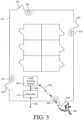
- FIG. 3is a representational floor plan of care facility 205.
- a beacon 300is positioned near each exit 302 of facility 205 to detect when a wearer 304 of SRTD 200 is beyond some predetermined perimeter. If wearer 304 moves near beacon 300, local tracking system 206 is alerted via a wireless link 306. Local tracking system 206 then alerts subscriber 118 via a link 308. Subscriber 118 then notifies server 104 via communication link 210, so that server 104 can take appropriate actions such as, for example, activating LRTD 202. Once activated, server 104 can request and receive the current position of LRTD 202, and communicate that position to subscriber 118 and/or emergency responders.
- FIG. 4shows an example of tracking unit 102 embodied in a pair of removable footwear insoles 400R and 400L, configured for insertion into a right shoe 402R and left shoe 402L, respectively.
- Insole 400Lincludes LRTD 202 embedded within an insole body 404L
- insole 400Rincludes SRTD 200 embedded within another insole body 404R.
- Insoles 400R and 400Lare intended to be used in combination as a pair. However, a user could elect to use either insole 400R or 400L alone, and still achieve the benefits provided by the respective insole. For example, a user interested only in long range, outdoor tracking could use insole 400L, without insole 400R.
- insole 400Rwithout insole 400L.
- an insole without any tracking devicecan be used in the opposite shoe to maintain a consistent feel for the wearer.
- SRTD 200 of LRTD 202a particular tracking device
- footwear insoles 400L and 400Rallow footwear insoles 400L and 400R to be used in any other shoes that a wearer owns, even if those shoes are not necessarily designed for tracking devices. This is particularly desirable because the consumer is not limited to shoes designed specifically for tracking systems.
- FIG. 5shows a top perspective view of LRTD 202.
- LRTD 202includes a location determining device 500, a wireless communication device 502, a power source 504, and a charging system 506 all coupled to a printed circuit board (PCB) 508.
- PCBprinted circuit board
- Location determining device 500is, for example, a global positioning system (GPS) receiver mounted directly on PCB 508.
- Location determining device 500includes a GPS module 510 (shown in FIG. 6 ) mounted on a bottom surface 514 of PCB 508 and a GPS antenna 512 mounted on a top surface 516 of PCB 508.
- Module 510facilitates calculating the position of a user based on the timing of satellite signals received by GPS antenna 512.
- Wireless communication device 502is, for example, a wireless cellular modem that communicates with a wireless cellular network.
- Wireless communication device 502includes a subscriber identity module (SIM) card 518, a microprocessor 520, and a global system for mobile communications (GSM) antenna 522, all connected via PCB 508.
- SIMsubscriber identity module
- GSMglobal system for mobile communications
- SIM card 518 and microprocessor 520are mounted on bottom surface 514 of PCB 508, and GSM antenna 522 is mounted on top surface 516 of PCB 508.
- Power source 504is a rechargeable lithium polymer battery that provides power to LRTD 202.
- power source 504is connected to PCB 508 via a wired modular connector 524.
- the inventorshave found that modular connectors are sometimes preferred over direct solder connections because they maintain a reliable electrical connection during the forming of body 404L around LRTD 202.
- Modular connectors that connect components to PCB 508are also more robust in maintaining a reliable electrical connection when footwear insole 400L flexes during normal use.
- power source 504can be a flexible lithium ceramic battery (FLCB), to eliminate the bulky non-flexible properties inherent in other battery types.
- FLCBflexible lithium ceramic battery
- FLCB batteriescan be formed into various shapes, thereby making FLCB's desirable for oddly shaped form factors such as insoles.
- power source 504can be a miniature power generator that harnesses energy from the user's steps.
- power source 504can be disposed in a thin fireproof bag such as, for example, a liposack.
- a protective plate 526is formed, for example, from aluminum, which is relatively strong and light-weight.
- Charging system 506is operative to recharge power source 504.
- charging system 506is an inductive charge pad coupled to power source 504 indirectly through PCB 508.
- the inductive charge padprovides a means for charging power source 504 without the need for a direct conductive electrical connection outside of insole 404L. This is particularly advantageous in that LRTD 202 can be completely embedded in body 404L without any external terminals, thus improving reliability.
- FIG. 6shows a bottom view of LRTD 202.
- GPS module 510, SIM card 518, a microprocessor 520, and a modular battery connector receiver 600are mounted on bottom surface 514 of PCB 508.
- GSM antenna 522is positioned at the rear of PCB 508 and power source 504, charging system 506, and plate 526 are positioned in front of PCB 508.
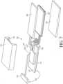
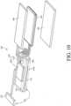
- FIG. 7shows a top perspective view of LRTD 202 with a housing 700 for protecting PCB 508 and components connected thereto from damage.
- housing 700partially encapsulates PCB 508. That is, housing 700 includes a recessed region 702 that receives PCB 508. Housing 700 extends above top surface 516 so as to prevent unwanted pressure from being exerted directly on components and electrical connections. The top of housing 700 forms a bridge over PCB 508 and the components and connection thereon.
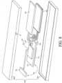
- FIG. 8shows a top perspective view of LRTD 202 with an alternate housing 800 for protecting tracking device 202 from damage during use.
- housing 800includes a top 802 and a bottom 804 fixed together to completely enclose LRTD 202 therein. This is advantageous, because housing 800 protects LRTD 202 from both mechanical damage and moisture damage. Completely enclosing LRDT 202 also protects LRDT 202 from damage by the material and process of molding LRDT 202 into insole body 404L.
- FIG. 9shows a top view of LRTD 202 disposed within a protective substrate 900.
- LRTD 202is vacuum sealed within an antistatic bag 900, to protect LRTD 202 from static electricity and moisture.
- bag 900prevents polyurethane (or other molding material) from entering any cavities on LRTD 202, which can disrupt connections and cause other damage when the polyurethane cures. Bag 900 also facilitates the clean removal of used devices from insole body 404L for reuse and/or refurbishing.
- protective bag 900can be made from a fire-proof material such as, for example, a liposack.
- FIG. 10shows a top perspective view of LRTD 202.
- LRTD 202additionally includes a protective layer 1000 formed around PCB 508 and the components and connectors mounted thereon.
- Layer 1000is, for example, an epoxy layer that protects PCB 508 and components mounted thereon from mechanical damage and moisture damage. Layer 1000 also protects the components during the process of forming of body 404L. The inventors have found that when body 404L is formed out of polyurethane, layer 1000 prevents uncured polyurethane from penetrating between PCB 508 and components mounted thereon. This is important because the polyurethane has a tendency to expand when it cures, thereby disconnecting components from PCB 508.
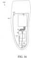
- FIG. 11shows the relative position of LRTD 202 within insole 400L.
- the material of body 404Lis shown transparent so that the positioning of LRTD 202 within body 404L is visible.
- Insole 400Lfurther includes a heal pad 1100 disposed on the bottom surface of body 404L and under LRTD 202. As shown, antenna 512 and 522, and charging system 506 are positioned just under the top surface of insole 400L.
- FIGs. 12A through 12Dillustrate one method for manufacturing insoles 400L and 400R.
- an insole mold 1200is provided.
- Mold 1200includes a pair (left and right) of insole shaped cavities 1202.
- a set of heal pads 1100are positioned at the heal region of cavities 1202. Heal pads 1100 keep LRTD 202 and SRTD 200 up off of the bottom of cavities 1202 and ensures that LRTD 202 and SRTD 200 are fully encapsulated in insole bodies 400L and 400R, respectively.
- mold 1200can include a set of bumps on the bottom surface of each cavity 1202 to facilitate polyurethane flow under LRTD 202 and SRTD 200.
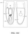
- a third stepas depicted in FIG. 12C , plate 526 and LRTD 202 are positioned in the left one of cavities 1202, and SRTD 200 is positioned in the right one of cavities 1202.
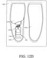
- a fourth stepas depicted in FIG. 12D , uncured polyurethane 1204 is poured into cavities 1202, thereby submerging LRTD 202, SRTD 200, plate 526, and heal pads 1100.
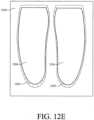
- cavities 1202are filled with polyurethane 1204, polyurethane 1204 is then cured to form bodies 404.
- insoles 400L and 400Rare removed from cavities 1202.
- FIG. 13shows a top view of an insole 1300L.
- Several componentsare substantially similar or identical to components of insole 400L. Therefore, those components are denoted by like numbers and their descriptions are omitted to avoid redundancy.
- Insole 1300Lincludes a body 404L and a LRTD 1302.
- LRTD 1302is substantially similar to LRTD 1302, except that the inductive charging pad of charging system 506 is replaced by a set of battery charging wires 1304 that extend out of body 404L.
- wires 1304are coiled within body 404L to reduce stress applied to wires 1304 and PCB 508 as the wearer of insole 1300L walks. As the wearer takes a step, coiled wires 1304 flex like a spring.
- body 404Lis shown transparent to show details of tracking LRTD 1302 that would otherwise not be visible.
- FIG. 14shows a top view of an insole 1400L.
- Insole 1400Lincludes a body 404L and a LRTD 1402.
- LRTD 1402is substantially similar to LRTD 1302 except that battery charging wires 1304 are replaced by a set of wires 1404 that extend out of body 404L, but are arranged differently.
- wires 1404are wrapped around PCB 508 to reduce stress applied to wires 1404 and PCB 508 as the wearer of insole 1400 walks. As the user takes a step, wires 1404 pull slightly against PCB 508 rather than against the solder joints where wires 1404 are attached to PCB 508.
- body 404Lis shown transparent so that the details of LRTD 1502 are visible.
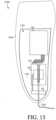
- FIG. 15shows a top view of an insole 1500L.
- Insole 1500includes a body 404L and a LRTD 1502.
- LRTD 1502is substantially similar to LRTD 1302 except that battery charging wires 1304 are replaced by a set of wires 1504 that extend out of body 404L, but are arranged differently.
- wires 1504are bent into a zig-zag pattern across PCB 508, which reduces stress applied to wires 1504 and PCB 508 as the wearer of insole 1500 walks.
- wires 1504flex like a spring.
- body 404Lis shown transparent so that the details of LRTD 1502 are visible.
- FIG. 16shows a top view of an insole 1600L.
- Insole 1600Lincludes a body 404L and a LRTD 1602.
- LRTD 1602is substantially similar to LRTD 402 except that the inductive charging pad of charging system 506 is replaced by a mini USB cable 1604 that is accessible from the exterior of body 404L.
- body 404Lis shown transparent so that the details of LRTD 1502 are visible.
- FIG. 17shows a rear view of insole 1600L wherein mini USB cable 1604 is accessible through body 404L.
- the socket of USB cable 1604is protected from debris and moisture by a resilient plug 1700, which can be removed to permit charging via a USB charger.
- FIG. 18shows a perspective view of an insole 1800.
- Insole 1800includes an opening 1802, an electronic device receptacle 1804, and an electronic device 1806.
- Opening 1802receives electronic device receptacle 1804, which includes an opening 1808 configured to receive a variety of electronic devices (i.e. electronic device 1806) designed with a complementary configuration.
- opening 1808includes a set of channels 1810 that receive a complimentary set of lips 1812 of electronic device 1806. Channels 1810 and lips 1812, together, prevent electronic device 1806 from being inserted into opening 1808 improperly.
- receptacle 1804includes means for retaining and selectively releasing (e.g., one or more detents, clips, frictional fit, etc.) device 1806 from receptacle 1804.
- electronic device 1806is a LRTD that includes substantially identical components and functionality as LRTD 202. It should be understood, however, that electronic device 1806 need not necessarily be limited to tracking systems. Electronic device 1806 can be any type of device that would be advantageous to carry in a footwear insole. Examples of such devices include, but are not limited to, a pedometer, a scale, health monitors (e.g., pulse sensor, temperature sensor, etc.), personal area network devices, and so on. Indeed, receptacle 1804 can receive, retain, and selectively release any device with a complementary configuration, whether electronic or not.
- the complementary receiver/device designprovides several important advantages. For example, the design allows users to swap out different devices for different circumstances, without the need to replace the footwear or the insole. Another important advantage is that incorporating the receiver into the insole instead of the device isolates the device from whatever manufacturing process is necessary to incorporate the receiver into the insole.
- FIGs. 19A through 19Cillustrate an alternate method of manufacturing insole 1800.
- a first stepas depicted in FIG. 19A , a set of heal pads 1900 and an electronic device receptacle 1804 are positioned in an insole mold 1902.
- polyurethane 1904is poured into the cavities of mold 1902, over heal pads 1900 and electronic device receptacle 1804.
- a third stepas depicted in FIG. 19C , polyurethane 1904 is cured and insoles 1800 are removed from mold 1902.
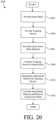
- FIG. 20is a flow chart summarizing an example method 2000 for manufacturing a footwear insole.
- a first step 2002an insole mold is provided.
- a tracking deviceis provided in a second step.
- an insole body materialis provided in a third step 2006.
- the tracking deviceis positioned in the insole mold.
- the insole body materialis introduced (poured, injected, etc.) into the mold over the tracking device.
- the insole body materialis cured/set, and the completed insole is removed from the mold.
Landscapes
- Engineering & Computer Science (AREA)
- Physics & Mathematics (AREA)
- General Physics & Mathematics (AREA)
- Health & Medical Sciences (AREA)
- General Health & Medical Sciences (AREA)
- Child & Adolescent Psychology (AREA)
- Business, Economics & Management (AREA)
- Emergency Management (AREA)
- Remote Sensing (AREA)
- Radar, Positioning & Navigation (AREA)
- Microelectronics & Electronic Packaging (AREA)
- Computer Networks & Wireless Communication (AREA)
- Human Computer Interaction (AREA)
- Footwear And Its Accessory, Manufacturing Method And Apparatuses (AREA)
Description
- This invention relates generally to personal tracking devices, and more particularly to personal tracking devices incorporated into footwear.
- Personal tracking devices are known in the art. One possibly desirable means of carrying a personal tracking device is to incorporate the personal tracking device into footwear. However, there are many obstacles to incorporating personal tracking devices into footwear, while maintaining the comfort, appearance, and affordability of the footwear.
- Previously, this has been accomplished with footwear that is specially designed to receive a tracking system. For example, some footwear has been designed with special cavities formed in the sole so as to provide a place to conceal a GPS device.
- There are problems associated with such footwear. For example, users have a limited selection of footwear styles. That is, users are limited to only those styles made available by the tracking system footwear manufacturer. Of course, such footwear is also likely to be more expensive than conventional footwear. In addition, most people have several pairs of shoes/footwear for different occasions. Having several pairs of GPS enabled footwear would be cost-prohibitive for many potential users.
- Another problem with tracking devices that use satellite signals is that the tracking devices can be nonfunctional in certain areas (e.g., inside of buildings) where the satellite signals cannot be received. In addition, the battery life of the tracking device can be diminished if the device is constantly searching for a signal or otherwise operating when not needed.
- What is needed, therefore, is a tracking system that can be incorporated into footwear that is not specifically designed to receive tracking devices. What is also needed is a tracking device that can be easily transferred from one pair of footwear to another. What is also needed is a tracking device that can be used interchangeably with multiple different pairs of footwear. What is also needed is a tracking device that operates satisfactorily when worn indoors for extended periods of time.
WO 2011/133780 A2 discloses a multilayer insole for removable placement in an article of footwear, the multilayer insole including a bottom insole layer having a top side, a top insole layer having an underside, an intermediate layer for joining the bottom insole layer with the top insole layer, a location data receiving means for receiving an input signal relating to a location of the insole, and a location data transmitting means for transmitting an output signal relating to the location of the insole, wherein the location data receiving means and the location data transmitting means are both integrally associated with the multilayer insole.US 2010/0033321 A1 discloses a separated tracking device that includes a first portion including a location determining device operative to receive signals from a positioning system, a wireless communication device operative to communicate the location data from the first portion to a second portion of the tracking device, the second portion including a wireless data transceiver operable to transmit the location data to a remote server. In an embodiment, the first portion of the tracking device is attached to a first shoe and the second portion of the tracking device is incorporated in a second shoe.US 2005/0073409 A1 discloses an object locator system for obtaining information about the location of an individual, animal or moveable object, having a lightweight, attached object locator, that is present in a region served by a two-way paging system and a global positioning satellite system. The object locator may be selectively activated to conserve power or enabled to respond only when beyond a boundary.- The present invention overcomes the problems associated with the prior art by providing a tracking device that can be easily transferred between different pairs of footwear. The present invention also overcomes the problems associated with the prior art by providing a tracking device that includes a long-range tracking device and a short-range tracking device. The invention facilitates tracking a wearer within a predefined space (e.g., a patient care facility) using the short-range tracking device, and tracking the wearer with the long-range tracking device when the wearer leaves the predefined space. The tracking device is contained within a pair of removable footwear insoles, with the short-range tracking device disposed in one of the insoles and the long-range tracking device disposed within the other of the insoles.
- The present invention provides an object tracking system according to
claim 1 and a method of tracking an object according to claim 9. - The object tracking system includes a first insole body and a first tracking device. The first insole body is configured for removable insertion into footwear and configured to engage the plantar region of a foot of a wearer. The first tracking device is disposed at least partially within the first insole body.
- The first tracking device includes a location determining device, a wireless communication device, and a power source. The location determining device is electrically coupled to the wireless communication device, and both location determining device and the wireless communication device are electrically coupled to the power source (e.g., via a modular connector).
- There is also disclosed an example where the power source is a battery. In an example, the battery is a lithium polymer battery. Alternatively, the battery can be a flexible lithium ceramic battery. Optionally, the power source can include an electricity generator.
- Several alternative means for charging the battery are disclosed. According to one alternative, the footwear insole tracking system additionally includes an inductance charging element disposed at least partially within the first insole body and being electrically coupled to the battery. In another example, the footwear insole tracking system includes a wired electronic communication port electrically coupled to the first tracking device, being disposed at least partially within the first insole body, and being accessible from outside the first insole body. In yet another example, the footwear insole tracking system includes a set of wires electrically coupled to the first tracking device and extending from the first insole body.
- Several means for relieving stress on the wires are disclosed. In one example, the set of wires is coiled to facilitate flexing. In another example, the first tracking device includes a circuit board. The location determining device and the wireless communication device are coupled to the circuit board, and the set of wires is wrapped around the circuit board. In yet another example, the set of wires is arranged in a generally zig-zagged shape.
- Means for protecting the battery from damage and for protecting the wearer from the battery are provided in the insole. One example includes an optional fireproof enclosure disposed within the first insole body and surrounding the battery. As another option, the footwear insole tracking system can include a rigid plate disposed at least partially in the first insole body. The battery is then positioned above the rigid plate to protect the battery against puncture if, for example, the wearer steps on a nail that punctures the bottom of the footwear.
- Means for protecting the tracking device from the process of being incorporated into a footwear insole are also disclosed. For example, at least one of the location determining device and the wireless communication device is at least partially encapsulated in epoxy. As another option, the footwear insole tracking system can include a rigid housing disposed at least partially in the first insole body and covering at least a portion of the first tracking device. In an example, the rigid housing is an enclosed receptacle, and the location determining device and the wireless communication device are substantially enclosed within the receptacle.
- In an unclaimed example, the first tracking device is a long-range tracking device. The location determining device is a global positioning system signal receiver, and the wireless communication device is a cell phone modem, which includes a global system for mobile communication antenna. The footwear insole tracking system additionally includes a subscriber identification module card coupled to the wireless communication device and disposed at least partially in the first insole body. One or both of the location determining device and the wireless communication device include a flexible patch antenna disposed within the insole body. Optionally, at least one of the location determining device and the wireless communication device includes an antenna mounted directly on a circuit board.
- In an example, the location determining device includes a global positioning system antenna (GPS) mounted on a circuit board, and the location determining device and the wireless communication device are mounted on the same circuit board. The GPS antenna is located on one side of the circuit board, and a processing unit of the first tracking device is located on an opposite side of the circuit board. The subscriber identification module card of the first tracking device is also located on the opposite side of the circuit board.
- Alternate means for mounting a tracking device or any other type of device within a removable footwear insole are also disclosed. The mounting means include an electronic device receptacle disposed at least partially in the insole body and accessible from outside the insole body. The electronic device receptacle is configured to receive the first tracking device and/or any other type of device configured to fit within the receptacle. The insole body is formed around the receptacle by, for example, molding the insole body around the first tracking device.
- In an example, the first insole body is formed from polyurethane material. Optionally, the first tracking device is fully encapsulated within the first insole body.
- Alternatively, the first tracking device can be a short-range tracking device detectable within a limited space by a local tracking system.
- The first tracking device is a short-range tracking device detectable within a limited space by a local tracking system. The footwear insole tracking system additionally includes a second insole body configured for removable insertion into footwear and configured to engage the plantar region of an opposite foot of the wearer, with respect to the first insole body. A long-range tracking device is disposed at least partially within the second insole body and is trackable outside the limited space by a long-range tracking system. In an example, the long-range tracking device includes a location determining device, a wireless communication device electrically coupled to the location determining device, and a power source electrically coupled to the location determining device and the wireless communication device.
- A method of tracking an object is also disclosed. The method includes attaching a short-range tracking device to the object and attaching a long-range tracking device to the object. The method additionally includes determining when the object has left a predefined area using the short-range tracking device, and activating the long-range tracking device when it is determined that the object has left the predefined area. The method continues by tracking the object outside the predefined are with the long-range tracking device.
- The present invention is described with reference to the following drawings, wherein like reference numbers denote substantially similar elements:
FIG. 1 is a block diagram of a system for tracking and/or monitoring one or more tracking units;FIG. 2 is a block diagram showing the tracking unit ofFIG. 1 in greater detail;FIG. 3 is a representational floor plan of care facility employing the tracking system ofFIG. 2 ;FIG. 4 is a side view of footwear having insoles with embedded tracking units;FIG. 5 is a top perspective view of the long-range tracking device ofFIG. 2 ;FIG. 6 is a bottom view of the long-range tracking device ofFIG. 2 ;FIG. 7 is a top perspective view of the long-range tracking device ofFIG. 2 including a semi-housing structure;FIG. 8 is a top perspective view of the long-range tracking device ofFIG. 2 including a full housing structure;FIG. 9 is a top view of the long-range tracking device ofFIG. 2 disposed in a protective substrate;FIG. 10 is a top perspective view of the long-range tracking device ofFIG. 2 further including a substrate layer;FIG. 11 is a top view of the tracking device ofFIG. 10 disposed in an insole;FIG. 12A depicts a first step of manufacturing the insole ofFIG. 8 ;FIG. 12B depicts a second step of manufacturing the insole ofFIG. 8 ;FIG. 12C depicts a third step of manufacturing the insole ofFIG. 8 ;FIG. 12D depicts a fourth step of manufacturing the insole ofFIG. 8 ;FIG. 12E depicts a fifth step of manufacturing the insole ofFIG. 8 ;FIG. 13 is a top view of an insole;FIG. 14 is a top view of an insole;FIG. 15 is a top view of an insole;FIG. 16 is a top view of an insole;FIG. 17 is a rear view of the insole ofFIG. 16 ;FIG. 18 is a perspective view of an electronic device receiving insole;FIG. 19A depicts a first step of manufacturing the insole ofFIG. 18 ;FIG. 19B depicts a second step of manufacturing the insole ofFIG. 18 ;FIG. 19C depicts a third step of manufacturing the insole ofFIG. 18 ;FIG. 20 is a flowchart summarizing one method for manufacturing a footwear insole with an embedded tracking device; andFIG. 21 is a flowchart summarizing one method for tracking an object.- The present invention overcomes problems associated with the prior art, by providing a footwear insole with an embedded tracking device. The present invention also overcomes problems associated with the prior art, by providing a tracking device that includes a long-range tracking device and a short-range tracking device. In the following description, numerous specific details are set forth (e.g., particular electronic components) in order to provide a thorough understanding of the invention. Those skilled in the art will recognize, however, that the invention may be practiced apart from these specific details. In other instances, details of well-known footwear insole manufacturing and electronics assembly practices and components have been omitted, so as not to unnecessarily obscure the present invention.
FIG. 1 is a block diagram of asystem 100 for tracking and/or monitoring one or more tracking units 102(1-m) and for providing customized augmented location data to each of a plurality of subscribers 118 (1-p) associated with the tracking units 102(1-m).System 100 includes a plurality of tracking units 102(1-m), one or more servers 104(1-n), asubscriber profile database 106, and atracking interface 112, all intercommunicating via aninternal network 114.System 100 also includes one or more subscribers systems 118(1-p), which communicate with an internetwork 122 (e.g., the Internet).Internal network 114 is also connected to internetwork 122 through afirewall 124, which provides a measure of security forinternal network 114 against incoming threats frominternetwork 122. As will later be described in further detail, eachtracking unit 102 is adapted to be disposed in footwear such that the wearer can be tracked by one or more ofsubscribers 118.- The elements of tracking
system 100 provide the following general functions. Tracking units 102(1-m) provide geographical location data (e.g., latitude and longitude coordinates, etc.) indicating their geographical locations to servers 104(1-n) via trackinginterface 112. In addition, tracking units 102(1-m) can also be tracked by a local subscriber tracking system, as will be explained in greater detail below. Servers 104(1-n) perform tracking services for subscribers using subscriber systems 118(1-p) and augment location data received from tracking units 102(1-m) so that the subscribers using subscriber systems 118 (1-p) can track and/or monitor their associated tracking unit(s) 102(1-m) in a customized, augmented manner.Subscriber profile database 106 stores information, including customized augmentation preferences, associated with each subscriber. Servers 104(1-n) augment and transmit location data to subscribers using subscriber systems 118(1-p).Tracking interface 112 receives data and commands from servers 104(1-n) (e.g., location request signals, control routines, etc.) and transmits the data and commands to the destination tracking unit 102(1-m).Tracking interface 112 also receives data (e.g., location data, bio-metric sensor readings, alert signals, etc.) from tracking units 102(1-m) and provides the received data to one or more servers 104(1-n). In the present embodiment, trackinginterface 112 interfaces with tracking units 102(1-m) wirelessly, for example via awireless communication link 113. Indeed,wireless communication link 113 represents any means of wireless communication, now known or yet to be discovered, that facilitates communication betweenfootwear insole 102 andsubscriber server 104 including, but not limited to cellular networks (e.g., CDMA and GSM), satellite networks, WIFI networks, and radio communication. - Responsive to a command from
subscriber server 104, trackingunit 102 determines its location using location signals received from apositioning system 126 and transmits data indicative of the determined position back tosubscriber server 104.Positioning system 126 represents any type of satellite or terrestrial based positioning system that transmits signals that can be used to determine location. For example, a global positioning system (GPS) currently in use employs a plurality of satellites that continuously transmit signals. GPS receivers can calculate location by determining the difference in the time of receipt of signals from different satellites. GPS technology is well known, and so will not be described in detail herein. - As an alternative to a GPS type system,
positioning system 126 can be incorporated intowireless communication link 113. For example, wireless telephone networks now have the capability of determining the location of mobile telephone handsets based on signals from a plurality of signal towers in the network.Wireless communication link 113 can then provide the determined location directly to trackingunit 102, which in turn can communicate the location tosubscriber server 104. As a result,positioning system 126 can be thought of as either optional or as being incorporated intowireless communication link 113. - Subscriber systems 118(1-p) are human users and/or electronic devices that allow the human subscriber/user (e.g., a person with an interest in the location of the person wearing tracking unit 102) to electronically interact with servers 104(1-n) to define data augmentation preferences and to obtain customized augmented location data and alerts from their associated tracking units(s) 102. For instance, when a user initially subscribes to the
tracking system 100, the subscriber optionally sets up a username and password with one ofservers 104 via asubscriber system 118. Thatparticular server 104 would also create a subscriber profile uniquely associated with that subscriber and then allow the subscriber (again via subscriber system 118) to customize what augmentation routines the subscriber would like use to augment the location data received from histracking unit 102.Server 104 then stores the subscriber's profile insubscriber database 106. In addition, if a subscriber registers more than one trackingunits 102 withsystem 100, then a separate subscriber profile can be created insubscriber profile database 106 for eachtracking unit 102 associated with the subscriber. Alternatively, multiple trackingunits 102 can be associated with a single subscriber profile indatabase 106, for example, where the subscriber wishes to run the same augmentation routines on the location data provided by each associatedtracking unit 102. The subscriber profiles indatabase 106 also contain any other pertinent information associated with a subscriber such as personal information (address, telephone number, etc.), payment information such as a credit card number, a network identifier uniquely identifying thesubscriber 118 on thenetwork 122, etc. Subscribers 118(1-p) represent individuals with an interest in the location of the person wearingtracking unit 102. Forexample tracking system 100 can be used by parents to locate children, by service departments to locate emergency service personal in the field, and so on. - Generally, a
server 104 operates as follows to provide customized augmented location data to a subscriber using asubscriber system 118.Server 104, upon receiving the location data from atracking unit 102, associates the location data with a particular subscriber, augments the location according to one or more of a plurality of predetermined routines based on information associated with the subscriber, and then presents the augmented location data to the subscriber viainternetwork 122 and an associatedsubscriber system 118. Note that the predetermined augmentation routines can be defined in the subscriber's profile stored insubscriber profile database 106, or could have been input manually by the subscriber viasubscriber system 118 before the location data was augmented. - It should be noted that the present embodiment is described with respect to "subscribers" using
subscriber systems 118, implying that the subscribers pay for the services provided by trackingsystem 100. For example, subscription services offered for a subscriber's use ofsystem 100 could vary by price based on any number of criteria such as the complexity of the augmented location data provided, the number of augmentation routines employed by the subscriber, the augmented location data delivery method, the number of trackingunits 102 associated with a subscriber, and so on. However,tracking system 100 is not limited to a subscription type business model. For example, access tosystem 100 could be provided to the subscribers for free, andsystem 100 could rely on some other business model to raise revenue. - Tracking units 102(1-m) optionally include software and/or firmware that facilitates communication directly with one or more of subscribers 118(1-p) via a
telecommunications carrier 130. FIG. 2 is a block diagram showingtracking unit 102 in greater detail to include a short-range tracking device (SRDT) 200 and a long-range tracking device (LRTD) 202. In addition, onesubscriber system 118 is shown to be included in a facility 205 (e.g., a hospital, long term care unit, etc.) along with alocal tracking system 206.SRTD 200 includes, for example, a radio frequency identification (RFID) device that enables trackingunit 102 to be tracked in locations where satellite signals cannot be detected byLRTD 202 and/or where battery life of the tracking unit is a consideration. As another option,SRTD 200 can include a BLUETOOTH® low energy (BLE) device. Indeed,SRTD 200 can be any device capable of being tracked locally.- In this example, tracking
unit 102 is being worn by a patient infacility 205. When trackingunit 102 is within the perimeters offacility 205,SRTD 200 communicates location data to (or is simply detectable by)local tracking system 206 via awireless link 208, whileLRTD 202 remains inactive. If the patient wearingtracking unit 102 leaves the perimeter offacility 205,LRTD 202 is activated andSRTD 200 is optionally deactivated. There are many ways to detect thattracking unit 102 is beyond the perimeters offacility 205. For example,local tracking system 206 could lose communication withSRTD 200. Optionally,local tracking system 206 could detect thattracking unit 102 has exceeded the allowable range (or no longer be able to detect tracking unit 102). As yet another option,local tracking system 206 can detectSRTD 200 passing an unauthorized point (e.g., out a door of facility 205). Whatever type of SRTD is used, oncelocal tracking system 206 determines thatSRTD 200 has leftfacility 205,local tracking system 206 notifiessubscriber system 118, which communicates an alert toserver 104 through alink 210. Once the alert is received,server 104 sends tracking unit 102 a communication, via trackinginterface 112, instructingtracking unit 102 to activateLRTD 202 and (optionally)deactivate SRTD 200. As another option, in embodiments whereSRTD 200 is able to detect that it is out of range,SRTD 200 can activateLRTD 202. When activated,LRTD 202 receives wireless signals 212 frompositioning system 126, calculates location data, and relays the current location toserver 104 via trackinginterface 112 andwireless communication link 113. Then,server 104 can communicate the location of LRTD tosubscriber 118 and/or other emergency personnel. - If tracking
unit 102 enters back into the perimeters defined bylocal tracking system 206, wireless link 208 (or mere detection) can be reestablished. Once it is determined thatSRTD 200 is back infacility 205,LRTD 202 can be deactivated andSTRD 200 can be reactivated (in embodiments whereSTRD 200 is an active device). FIG. 3 is a representational floor plan ofcare facility 205. In this particular embodiment, abeacon 300 is positioned near eachexit 302 offacility 205 to detect when awearer 304 ofSRTD 200 is beyond some predetermined perimeter. Ifwearer 304 moves nearbeacon 300,local tracking system 206 is alerted via awireless link 306.Local tracking system 206 then alertssubscriber 118 via alink 308.Subscriber 118 then notifiesserver 104 viacommunication link 210, so thatserver 104 can take appropriate actions such as, for example, activatingLRTD 202. Once activated,server 104 can request and receive the current position ofLRTD 202, and communicate that position tosubscriber 118 and/or emergency responders.FIG. 4 shows an example of trackingunit 102 embodied in a pair ofremovable footwear insoles right shoe 402R and leftshoe 402L, respectively.Insole 400L includesLRTD 202 embedded within aninsole body 404L, andinsole 400R includesSRTD 200 embedded within anotherinsole body 404R.Insoles insole insole 400L, withoutinsole 400R. Conversely, a user interested only in tracking within a facility could use insole 400R, withoutinsole 400L. In such cases, an insole without any tracking device can be used in the opposite shoe to maintain a consistent feel for the wearer. Of course, it does not matter into which insole (right or left) a particular tracking device (SRTD 200 of LRTD 202) is incorporated.- The removability of
footwear insoles shoes footwear insoles FIG. 5 shows a top perspective view ofLRTD 202.LRTD 202 includes alocation determining device 500, awireless communication device 502, apower source 504, and acharging system 506 all coupled to a printed circuit board (PCB) 508.Location determining device 500 is, for example, a global positioning system (GPS) receiver mounted directly onPCB 508.Location determining device 500 includes a GPS module 510 (shown inFIG. 6 ) mounted on abottom surface 514 ofPCB 508 and aGPS antenna 512 mounted on atop surface 516 ofPCB 508.Module 510 facilitates calculating the position of a user based on the timing of satellite signals received byGPS antenna 512.Wireless communication device 502 is, for example, a wireless cellular modem that communicates with a wireless cellular network.Wireless communication device 502 includes a subscriber identity module (SIM)card 518, amicroprocessor 520, and a global system for mobile communications (GSM)antenna 522, all connected viaPCB 508. In particular,SIM card 518 andmicroprocessor 520 are mounted onbottom surface 514 ofPCB 508, andGSM antenna 522 is mounted ontop surface 516 ofPCB 508.Power source 504 is a rechargeable lithium polymer battery that provides power to LRTD 202. In the example embodiment,power source 504 is connected toPCB 508 via a wiredmodular connector 524. The inventors have found that modular connectors are sometimes preferred over direct solder connections because they maintain a reliable electrical connection during the forming ofbody 404L aroundLRTD 202. Modular connectors that connect components toPCB 508 are also more robust in maintaining a reliable electrical connection whenfootwear insole 400L flexes during normal use. As an alternative,power source 504 can be a flexible lithium ceramic battery (FLCB), to eliminate the bulky non-flexible properties inherent in other battery types. In addition, FLCB batteries can be formed into various shapes, thereby making FLCB's desirable for oddly shaped form factors such as insoles. As yet another alternative,power source 504 can be a miniature power generator that harnesses energy from the user's steps. Although not shown inFIG. 5 ,power source 504 can be disposed in a thin fireproof bag such as, for example, a liposack. To prevent damage that can occur if a user steps on a sharp object,power source 504 is protected by aprotective plate 526. In this example,protective plate 526 is formed, for example, from aluminum, which is relatively strong and light-weight.Charging system 506 is operative to rechargepower source 504. In this particular embodiment, chargingsystem 506 is an inductive charge pad coupled topower source 504 indirectly throughPCB 508. The inductive charge pad provides a means for chargingpower source 504 without the need for a direct conductive electrical connection outside ofinsole 404L. This is particularly advantageous in that LRTD 202 can be completely embedded inbody 404L without any external terminals, thus improving reliability.FIG. 6 shows a bottom view ofLRTD 202. In this example,GPS module 510,SIM card 518, amicroprocessor 520, and a modularbattery connector receiver 600 are mounted onbottom surface 514 ofPCB 508. As shown,GSM antenna 522 is positioned at the rear ofPCB 508 andpower source 504, chargingsystem 506, andplate 526 are positioned in front ofPCB 508.FIG. 7 shows a top perspective view ofLRTD 202 with ahousing 700 for protectingPCB 508 and components connected thereto from damage. In this example,housing 700 partially encapsulatesPCB 508. That is,housing 700 includes a recessedregion 702 that receivesPCB 508.Housing 700 extends abovetop surface 516 so as to prevent unwanted pressure from being exerted directly on components and electrical connections. The top ofhousing 700 forms a bridge overPCB 508 and the components and connection thereon.FIG. 8 shows a top perspective view ofLRTD 202 with analternate housing 800 for protectingtracking device 202 from damage during use. In this example,housing 800 includes a top 802 and a bottom 804 fixed together to completely encloseLRTD 202 therein. This is advantageous, becausehousing 800 protectsLRTD 202 from both mechanical damage and moisture damage. Completely enclosingLRDT 202 also protectsLRDT 202 from damage by the material and process ofmolding LRDT 202 intoinsole body 404L.FIG. 9 shows a top view ofLRTD 202 disposed within aprotective substrate 900. In the example embodiment,LRTD 202 is vacuum sealed within anantistatic bag 900, to protectLRTD 202 from static electricity and moisture. In addition,bag 900 prevents polyurethane (or other molding material) from entering any cavities onLRTD 202, which can disrupt connections and cause other damage when the polyurethane cures.Bag 900 also facilitates the clean removal of used devices frominsole body 404L for reuse and/or refurbishing. Optionally,protective bag 900 can be made from a fire-proof material such as, for example, a liposack.FIG. 10 shows a top perspective view ofLRTD 202. In this example,LRTD 202 additionally includes aprotective layer 1000 formed aroundPCB 508 and the components and connectors mounted thereon.Layer 1000 is, for example, an epoxy layer that protectsPCB 508 and components mounted thereon from mechanical damage and moisture damage.Layer 1000 also protects the components during the process of forming ofbody 404L. The inventors have found that whenbody 404L is formed out of polyurethane,layer 1000 prevents uncured polyurethane from penetrating betweenPCB 508 and components mounted thereon. This is important because the polyurethane has a tendency to expand when it cures, thereby disconnecting components fromPCB 508.FIG. 11 shows the relative position ofLRTD 202 withininsole 400L. In this view, the material ofbody 404L is shown transparent so that the positioning ofLRTD 202 withinbody 404L is visible.Insole 400L further includes a healpad 1100 disposed on the bottom surface ofbody 404L and underLRTD 202. As shown,antenna system 506 are positioned just under the top surface ofinsole 400L.FIGs. 12A through 12D illustrate one method for manufacturinginsoles FIG. 12A , aninsole mold 1200 is provided.Mold 1200 includes a pair (left and right) of insole shapedcavities 1202. In a second step, as depicted inFIG. 12B , a set of healpads 1100 are positioned at the heal region ofcavities 1202.Heal pads 1100 keepLRTD 202 andSRTD 200 up off of the bottom ofcavities 1202 and ensures thatLRTD 202 andSRTD 200 are fully encapsulated ininsole bodies mold 1200 can include a set of bumps on the bottom surface of eachcavity 1202 to facilitate polyurethane flow underLRTD 202 andSRTD 200.- In a third step, as depicted in
FIG. 12C ,plate 526 andLRTD 202 are positioned in the left one ofcavities 1202, andSRTD 200 is positioned in the right one ofcavities 1202. Then, in a fourth step, as depicted inFIG. 12D ,uncured polyurethane 1204 is poured intocavities 1202, thereby submergingLRTD 202,SRTD 200,plate 526, and healpads 1100. Oncecavities 1202 are filled withpolyurethane 1204,polyurethane 1204 is then cured to form bodies 404. Finally,insoles cavities 1202. Although the manufacturing process is described using an open top mold, a closed mold can be used to provide contour to the upper surfaces of insole bodies 404. FIG. 13 shows a top view of aninsole 1300L. Several components are substantially similar or identical to components ofinsole 400L. Therefore, those components are denoted by like numbers and their descriptions are omitted to avoid redundancy.Insole 1300L includes abody 404L and aLRTD 1302.LRTD 1302 is substantially similar toLRTD 1302, except that the inductive charging pad of chargingsystem 506 is replaced by a set ofbattery charging wires 1304 that extend out ofbody 404L. As shown,wires 1304 are coiled withinbody 404L to reduce stress applied towires 1304 andPCB 508 as the wearer ofinsole 1300L walks. As the wearer takes a step, coiledwires 1304 flex like a spring. As previously mentioned,body 404L is shown transparent to show details of trackingLRTD 1302 that would otherwise not be visible.FIG. 14 shows a top view of aninsole 1400L.Insole 1400L includes abody 404L and aLRTD 1402.LRTD 1402 is substantially similar toLRTD 1302 except thatbattery charging wires 1304 are replaced by a set ofwires 1404 that extend out ofbody 404L, but are arranged differently. As shown,wires 1404 are wrapped aroundPCB 508 to reduce stress applied towires 1404 andPCB 508 as the wearer of insole 1400 walks. As the user takes a step,wires 1404 pull slightly againstPCB 508 rather than against the solder joints wherewires 1404 are attached toPCB 508. Again,body 404L is shown transparent so that the details ofLRTD 1502 are visible.FIG. 15 shows a top view of aninsole 1500L. Insole 1500 includes abody 404L and aLRTD 1502.LRTD 1502 is substantially similar toLRTD 1302 except thatbattery charging wires 1304 are replaced by a set ofwires 1504 that extend out ofbody 404L, but are arranged differently. As shown,wires 1504 are bent into a zig-zag pattern acrossPCB 508, which reduces stress applied towires 1504 andPCB 508 as the wearer of insole 1500 walks. As the user takes a step,wires 1504 flex like a spring. Again,body 404L is shown transparent so that the details ofLRTD 1502 are visible.FIG. 16 shows a top view of aninsole 1600L.Insole 1600L includes abody 404L and aLRTD 1602.LRTD 1602 is substantially similar to LRTD 402 except that the inductive charging pad of chargingsystem 506 is replaced by amini USB cable 1604 that is accessible from the exterior ofbody 404L. Again,body 404L is shown transparent so that the details ofLRTD 1502 are visible.FIG. 17 shows a rear view ofinsole 1600L whereinmini USB cable 1604 is accessible throughbody 404L. During use, the socket ofUSB cable 1604 is protected from debris and moisture by aresilient plug 1700, which can be removed to permit charging via a USB charger.FIG. 18 shows a perspective view of aninsole 1800.Insole 1800 includes anopening 1802, anelectronic device receptacle 1804, and anelectronic device 1806.Opening 1802 receiveselectronic device receptacle 1804, which includes anopening 1808 configured to receive a variety of electronic devices (i.e. electronic device 1806) designed with a complementary configuration. As shown,opening 1808 includes a set ofchannels 1810 that receive a complimentary set oflips 1812 ofelectronic device 1806.Channels 1810 andlips 1812, together, preventelectronic device 1806 from being inserted intoopening 1808 improperly. Although not shown in the view ofFIG. 18 ,receptacle 1804 includes means for retaining and selectively releasing (e.g., one or more detents, clips, frictional fit, etc.)device 1806 fromreceptacle 1804.- In the example embodiment,
electronic device 1806 is a LRTD that includes substantially identical components and functionality asLRTD 202. It should be understood, however, thatelectronic device 1806 need not necessarily be limited to tracking systems.Electronic device 1806 can be any type of device that would be advantageous to carry in a footwear insole. Examples of such devices include, but are not limited to, a pedometer, a scale, health monitors (e.g., pulse sensor, temperature sensor, etc.), personal area network devices, and so on. Indeed,receptacle 1804 can receive, retain, and selectively release any device with a complementary configuration, whether electronic or not. - The complementary receiver/device design provides several important advantages. For example, the design allows users to swap out different devices for different circumstances, without the need to replace the footwear or the insole. Another important advantage is that incorporating the receiver into the insole instead of the device isolates the device from whatever manufacturing process is necessary to incorporate the receiver into the insole.
FIGs. 19A through 19C illustrate an alternate method ofmanufacturing insole 1800. In a first step, as depicted inFIG. 19A , a set of healpads 1900 and anelectronic device receptacle 1804 are positioned in aninsole mold 1902. Then in a second step, as depicted inFIG. 19B ,polyurethane 1904 is poured into the cavities ofmold 1902, over healpads 1900 andelectronic device receptacle 1804. Finally, in a third step, as depicted inFIG. 19C ,polyurethane 1904 is cured andinsoles 1800 are removed frommold 1902.FIG. 20 is a flow chart summarizing anexample method 2000 for manufacturing a footwear insole. In afirst step 2002, an insole mold is provided. Then, in asecond step 2004, a tracking device is provided. Next, in athird step 2006, an insole body material is provided. Then, in afourth step 2008, the tracking device is positioned in the insole mold. Next, in afifth step 2010, the insole body material is introduced (poured, injected, etc.) into the mold over the tracking device. Finally, in asixth step 2012, the insole body material is cured/set, and the completed insole is removed from the mold.FIG. 21 is a flow chart summarizing anexample method 2100 of tracking an object. In afirst step 2102, a short-range tracking device is attached to an object and, in asecond step 2104, a long-range tracking device is attached to the same object. Then, in athird step 2106, the short-range tracking device is used to determine when the object leaves a predetermined area. Next, in afourth step 2108, the long-range tracking device is activated. Then, in afifth step 2110, the object is tracked using the long-range tracking device.
Claims (14)
- An object tracking system comprising:a short-range tracking device (200) attached to an object (304);a long-range tracking device (202) attached to the object (304);a local tracking system (206) configured to determine when the object (304) has left a predefined area (205) using the short-range tracking device (200);the long-range tracking device (202) configured to be activated when it is determined that the object (304) has left the predefined area (205);a long-range tracking system (100) configured to track the object (304) outside the predefined area (205) with the long-range tracking device (202);a first insole body (404R) configured for removable insertion into footwear (402R) and configured to engage the plantar region of a foot of a wearer; anda second insole body (404L) configured for removable insertion into footwear (402L) and configured to engage the plantar region of an opposite foot of the wearer; and whereinthe short-range tracking device (200) is disposed at least partially within the first insole body (404R) and is detectable within the predefined area (205) by the local tracking system (206); andthe long-range tracking device (202) is disposed at least partially within the second insole body (404L) and is trackable outside the predefined area (205) by the long-range tracking system (100).
- The object tracking system of Claim 1, wherein the long-range tracking device (202) includes:a location determining device (500);a wireless communication device (502) electrically coupled to the location determining device (500); anda power source (504) electrically coupled to the location determining device (500) and the wireless communication device (502).
- The object tracking system of Claim 2, further comprising a fireproof enclosure (900) disposed at least partially within the second insole body (404L) and surrounding the power source (504).
- The object tracking system of Claim 2, further comprising:a rigid plate (526) disposed at least partially in the second insole body (404L); and whereinthe second insole body (404L) includes a top surface adapted to engage the plantar region of the foot of the wearer; andthe power source (504) is disposed between the top surface of the second insole body (404L) and the rigid plate (526).
- The object tracking system of Claim 2, wherein the power source (504) includes a flexible lithium ceramic battery.
- The object tracking system of any preceding Claim, wherein the short-range tracking device (200) includes a BLUETOOTH® low energy (BLE) device.
- The object tracking system of any preceding Claim, wherein:the first insole body (404R) does not include a long-range tracking device (202); andthe second insole body (404L) does not include a short-range tracking device (200).
- The object tracking system of any preceding Claim, wherein:at least one of the first insole body and the second insole body includes an electronic device receptacle (1804) disposed within the insole body; andthe electronic device receptacle (1804) is configured to selectively receive an electronic device (1806) from outside a rear sidewall of the insole body, to retain and house the electronic device (1806) within the insole body during use of the insole (1800), and to selectively release the electronic device (1806) to facilitate removal and replacement of the electronic device (1806).
- A method of tracking an object (304) using a first insole body (404R) and a second insole body (404L), the method comprising:disposing a short-range tracking device (200) at least partially within a first insole body (404R), which is configured for removable insertion into footwear (402R) and configured to engage the plantar region of a foot of a wearer, wherein the short-range tracking device (200) is detectable within the predefined area (205) by a local tracking system (206);disposing a long-range tracking device (202) at least partially within the second insole body (404L), which is configured for removable insertion into footwear (402L) and configured to engage the plantar region of an opposite foot of the wearer, and wherein the long-range tracking device (202) is trackable outside the predefined area (205) by a long-range tracking system (100);determining when the object (304) has left a predefined area (205) using the short-range tracking device (200);activating the long-range tracking device (202) when it is determined that the object (304) has left the predefined area (205); andtracking the object (304) outside the predefined area (205) with the long-range tracking device (202).
- The method of Claim 9, wherein the short-range tracking device (200) is configured to communicate with the long-range tracking device (202) and to selectively activate the long-range tracking device (202).
- The method of Claim 10, further comprising:determining when the object (304) has re-entered the predefined area (205); anddeactivating the long-range tracking device (202) when it is determined that the object (304) has re-entered the predefined area (205).
- The method of any one of Claims 9-11, wherein the long-range tracking device (202) includes:a location determining device (500);a wireless communication device (502) electrically coupled to the location determining device (500); anda power source (504) electrically coupled to the location determining device (500) and the wireless communication device (502).
- The method of any one of Claims 9-12, wherein:the step of attaching the short-range tracking device (200) to the object (304) includes putting a first piece of footwear (402R) on a first foot of the object (304); andthe step of attaching the long-range tracking device (202) to the object (304) includes putting a second piece of footwear (402L) on a second foot of the object (304).
- The method of any one of Claims 9-13, wherein:the long-range tracking device (202) includes features (1812) adapted to engage complementary features (1810) of an electronic device receptacle (1804) formed in a removable footwear insole (1800);the electronic device receptacle (1804) is configured to selectively receive the long-range tracking device (202) from outside a rear sidewall of an insole body of the removable footwear insole (1800), to retain and house the long-range tracking device (202) within the insole body during use of the removable footwear insole (1800), and to selectively release the long-range tracking device (202) to facilitate removal and replacement of the long-range tracking device (202); andthe step of attaching the long-range tracking device (202) to the object (304) includes inserting the long range tracking device (202) in the electronic device receptacle (1804) of the removable footwear insole (1800) and inserting the removable footwear insole (1800) into the second piece of footwear (402L) prior to putting the second piece of footwear (402L) on the second foot of the object (304).
Applications Claiming Priority (3)
| Application Number | Priority Date | Filing Date | Title |
|---|---|---|---|
| US201361823062P | 2013-05-14 | 2013-05-14 | |
| US201361897485P | 2013-10-30 | 2013-10-30 | |
| PCT/US2014/000113WO2014185976A1 (en) | 2013-05-14 | 2014-05-14 | Footwear insole with embedded tracking device |
Publications (3)
| Publication Number | Publication Date |
|---|---|
| EP2996508A1 EP2996508A1 (en) | 2016-03-23 |
| EP2996508A4 EP2996508A4 (en) | 2017-02-08 |
| EP2996508B1true EP2996508B1 (en) | 2024-01-10 |
Family
ID=51898756
Family Applications (1)
| Application Number | Title | Priority Date | Filing Date |
|---|---|---|---|
| EP14798189.8AActiveEP2996508B1 (en) | 2013-05-14 | 2014-05-14 | Object tracking system and method thereof |
Country Status (3)
| Country | Link |
|---|---|
| US (5) | US9854872B2 (en) |
| EP (1) | EP2996508B1 (en) |
| WO (1) | WO2014185976A1 (en) |
Families Citing this family (27)
| Publication number | Priority date | Publication date | Assignee | Title |
|---|---|---|---|---|
| US10852069B2 (en) | 2010-05-04 | 2020-12-01 | Fractal Heatsink Technologies, LLC | System and method for maintaining efficiency of a fractal heat sink |
| EP2996508B1 (en)* | 2013-05-14 | 2024-01-10 | GTX Corp | Object tracking system and method thereof |
| US10010132B2 (en)* | 2014-01-13 | 2018-07-03 | Alexander Litvinov | Ventilation of footwear |
| US10433613B2 (en)* | 2014-01-13 | 2019-10-08 | Alexander Litvinov | Ventilation apparatus for footwear |
| WO2015123345A1 (en)* | 2014-02-11 | 2015-08-20 | Damman Kirk | Motion state notifying device and method |
| US20160128419A1 (en)* | 2014-11-07 | 2016-05-12 | Sherrie Ann Sanders | Shoe with tracking device |
| US20210177085A1 (en)* | 2014-11-07 | 2021-06-17 | Sherrie Ann Sanders | Shoe with tracking device and medication alert |
| US10168430B2 (en) | 2014-11-17 | 2019-01-01 | Adam Sobol | Wireless devices and systems for tracking patients and methods for using the like |
| KR20160097671A (en)* | 2015-02-09 | 2016-08-18 | 삼성전자주식회사 | Mobile device for controlling medical apparatus and method for controlling medical apparatus thereof |
| WO2016172864A1 (en)* | 2015-04-29 | 2016-11-03 | 北京爱丽丝幻橙科技有限公司 | Intelligent locating shoes and safety and health management system |
| KR101899362B1 (en) | 2015-09-14 | 2018-09-17 | 조태원 | multi-function smart shoes |
| JP5978477B1 (en)* | 2015-10-15 | 2016-08-24 | 株式会社おもてなしコーディネーター | Insole |
| FR3045987A1 (en)* | 2015-12-18 | 2017-06-23 | Orange | METHOD FOR MANAGING THE OPERATION OF A CONNECTED OBJECT |
| CN105427556A (en)* | 2015-12-23 | 2016-03-23 | 黎小斌 | A method for real-time positioning and tracking of positioning shoes, a control system and positioning shoes |
| GB2552177A (en)* | 2016-07-12 | 2018-01-17 | Leonard Cooper Mark | Tracking device |
| DE102017200484A1 (en) | 2017-01-13 | 2018-07-19 | Audi Ag | A system for outputting an output signal to a user |
| US10904646B2 (en)* | 2017-03-23 | 2021-01-26 | Plantiga Technologies Inc. | Movement sensing apparatus for use in a footwear item |
| FR3069505B1 (en) | 2017-07-27 | 2019-12-13 | Psa Automobiles Sa | PROTECTIVE DEVICE FOR THE VENTILATION AIR EXTRACTOR OF A MOTOR VEHICLE |
| CN113397265B (en) | 2017-10-25 | 2023-08-29 | 耐克创新有限合伙公司 | Automatic footwear system with preset user profile |
| US11382383B2 (en) | 2019-02-11 | 2022-07-12 | Brilliant Sole, Inc. | Smart footwear with wireless charging |
| JP7156504B2 (en)* | 2019-03-27 | 2022-10-19 | 日本電気株式会社 | Insole-type electronic device and method for manufacturing insole-type electronic device |
| EP4013297A4 (en) | 2019-08-16 | 2023-12-13 | Poltorak Technologies, LLC | DEVICE AND METHOD FOR MEDICAL DIAGNOSTICS |
| EP4033931A1 (en)* | 2019-09-24 | 2022-08-03 | Zhor Tech | Method and system for analysing the use of an item of footwear |
| JP7608850B2 (en) | 2020-03-05 | 2025-01-07 | 日本電気株式会社 | Electronic device, insole-type electronic device and monitoring system |
| CN113487835A (en)* | 2021-07-24 | 2021-10-08 | 陕西中医药大学 | Alarm device for preventing senile dementia patient from wandering away |
| KR102440038B1 (en) | 2022-02-08 | 2022-09-05 | (주)스마트메디칼디바이스 | Insole having location tracing function |
| US20250104543A1 (en)* | 2023-09-26 | 2025-03-27 | Tamika Blanchard | Movement tracking device producing an audible sound |
Citations (1)
| Publication number | Priority date | Publication date | Assignee | Title |
|---|---|---|---|---|
| US6172640B1 (en)* | 1999-06-18 | 2001-01-09 | Jennifer Durst | Pet locator |
Family Cites Families (16)
| Publication number | Priority date | Publication date | Assignee | Title |
|---|---|---|---|---|
| US6156028A (en)* | 1994-03-21 | 2000-12-05 | Prescott; Marvin A. | Method and apparatus for therapeutic laser treatment of wounds |
| AU5631796A (en)* | 1995-05-02 | 1996-11-21 | Tseng-Lu Chien | Super-thin lighting arrangement for a moving object |
| US7002217B2 (en)* | 2004-06-12 | 2006-02-21 | Solectron Corporation | Electrostatic discharge mitigation structure and methods thereof using a dissipative capacitor with voltage dependent resistive material |
| JP5122063B2 (en)* | 2004-08-17 | 2013-01-16 | 株式会社オハラ | Lithium ion secondary battery and solid electrolyte |
| EP1864266A2 (en)* | 2005-03-29 | 2007-12-12 | Symbol Technologies, Inc. | Smart radio frequency identification (rfid) items |
| US7474206B2 (en)* | 2006-02-06 | 2009-01-06 | Global Trek Xploration Corp. | Footwear with embedded tracking device and method of manufacture |
| JP2008218210A (en)* | 2007-03-05 | 2008-09-18 | Lenovo Singapore Pte Ltd | Battery pack and portable electronic device |
| US8077030B2 (en)* | 2008-08-08 | 2011-12-13 | Global Trek Xploration Corp. | Tracking system with separated tracking device |
| US8803703B2 (en)* | 2008-08-15 | 2014-08-12 | Siemens Energy, Inc. | Electronic circuitry for high-temperature environments |
| US8674810B2 (en) | 2009-04-22 | 2014-03-18 | Franwell, Inc. | Wearable RFID system |
| US9655405B2 (en) | 2010-04-22 | 2017-05-23 | Kristan Lisa Hamill | Insoles for tracking, data transfer systems and methods involving the insoles, and methods of manufacture |
| US20110296710A1 (en)* | 2010-06-02 | 2011-12-08 | Christian Holzer | Insole Comprising an Electronic Chip |
| US20120023785A1 (en)* | 2010-06-05 | 2012-02-02 | Nathaniel K. Barnes | Wireless remote controlled massaging footwear system |
| US20120266493A1 (en) | 2011-04-20 | 2012-10-25 | Harrison Moss | Footwear with Position Determination Unit |
| US20140266571A1 (en)* | 2013-03-12 | 2014-09-18 | Anirudh Sharma | System and method for haptic based interaction |
| EP2996508B1 (en)* | 2013-05-14 | 2024-01-10 | GTX Corp | Object tracking system and method thereof |
- 2014
- 2014-05-14EPEP14798189.8Apatent/EP2996508B1/enactiveActive
- 2014-05-14USUS14/120,374patent/US9854872B2/enactiveActive
- 2014-05-14WOPCT/US2014/000113patent/WO2014185976A1/enactiveApplication Filing
- 2017
- 2017-12-29USUS15/858,881patent/US10292453B2/enactiveActive
- 2019
- 2019-03-29USUS16/369,935patent/US10743615B2/enactiveActive
- 2020
- 2020-07-10USUS16/926,599patent/US11272761B2/enactiveActive
- 2022
- 2022-03-01USUS17/684,146patent/US20220287410A1/ennot_activeAbandoned
Patent Citations (2)
| Publication number | Priority date | Publication date | Assignee | Title |
|---|---|---|---|---|
| US6172640B1 (en)* | 1999-06-18 | 2001-01-09 | Jennifer Durst | Pet locator |
| US20050073409A1 (en)* | 1999-06-18 | 2005-04-07 | Jennifer Durst | Object locator |
Also Published As
| Publication number | Publication date |
|---|---|
| US20220287410A1 (en) | 2022-09-15 |
| US20150048942A1 (en) | 2015-02-19 |
| US20190350312A1 (en) | 2019-11-21 |
| EP2996508A1 (en) | 2016-03-23 |
| US20180125163A1 (en) | 2018-05-10 |
| US11272761B2 (en) | 2022-03-15 |
| US9854872B2 (en) | 2018-01-02 |
| US20200405010A1 (en) | 2020-12-31 |
| EP2996508A4 (en) | 2017-02-08 |
| US10292453B2 (en) | 2019-05-21 |
| US10743615B2 (en) | 2020-08-18 |
| WO2014185976A1 (en) | 2014-11-20 |
Similar Documents
| Publication | Publication Date | Title |
|---|---|---|
| US11272761B2 (en) | System and method for embedding a tracking device in a footwear insole | |
| US7474206B2 (en) | Footwear with embedded tracking device and method of manufacture | |
| US9131745B2 (en) | Footwear with embedded tracking device and method of manufacture | |
| US8077030B2 (en) | Tracking system with separated tracking device | |
| US20120266493A1 (en) | Footwear with Position Determination Unit | |
| CN105051565A (en) | Apparatus and methods for geolocating an individual with respect to a perimeter | |
| US10446004B2 (en) | System for monitoring state of user and related methods | |
| KR102343580B1 (en) | Improved positional awareness and locating system for cognitively impaired individuals and their caregivers | |
| CN202588456U (en) | Multifunctional general packet radio service (GPRS) location tracking location shoes | |
| US20240268518A1 (en) | Insole having position tracking function | |
| KR20150104666A (en) | Shoes Having Functions for Positioning and Wireless Communication | |
| CN204378034U (en) | A kind of shoes with positioning function based on mobile phone terminal | |
| US20220142292A1 (en) | Insole-type electronic device and method for manufacturing insole-type electronic device | |
| CN104997230A (en) | SOS safe and anti-loss smart shoes | |
| CN204091137U (en) | Shoe-pad | |
| WO2018011561A1 (en) | Tracking device | |
| CN209711671U (en) | Position shoes | |
| KR101408692B1 (en) | Insole with position pursuit function | |
| US12408006B1 (en) | Tracking device systems |
Legal Events
| Date | Code | Title | Description |
|---|---|---|---|
| PUAI | Public reference made under article 153(3) epc to a published international application that has entered the european phase | Free format text:ORIGINAL CODE: 0009012 | |
| 17P | Request for examination filed | Effective date:20151214 | |
| AK | Designated contracting states | Kind code of ref document:A1 Designated state(s):AL AT BE BG CH CY CZ DE DK EE ES FI FR GB GR HR HU IE IS IT LI LT LU LV MC MK MT NL NO PL PT RO RS SE SI SK SM TR | |
| AX | Request for extension of the european patent | Extension state:BA ME | |
| DAX | Request for extension of the european patent (deleted) | ||
| A4 | Supplementary search report drawn up and despatched | Effective date:20170110 | |
| RIC1 | Information provided on ipc code assigned before grant | Ipc:G01S 19/01 20100101ALI20170103BHEP Ipc:G08B 1/08 20060101ALI20170103BHEP Ipc:G01S 19/14 20100101ALI20170103BHEP Ipc:G01S 19/48 20100101ALI20170103BHEP Ipc:A43B 3/00 20060101AFI20170103BHEP Ipc:A43B 17/00 20060101ALI20170103BHEP Ipc:G08B 21/02 20060101ALI20170103BHEP | |
| STAA | Information on the status of an ep patent application or granted ep patent | Free format text:STATUS: EXAMINATION IS IN PROGRESS | |
| 17Q | First examination report despatched | Effective date:20191205 | |
| GRAP | Despatch of communication of intention to grant a patent | Free format text:ORIGINAL CODE: EPIDOSNIGR1 | |
| STAA | Information on the status of an ep patent application or granted ep patent | Free format text:STATUS: GRANT OF PATENT IS INTENDED | |
| INTG | Intention to grant announced | Effective date:20230707 | |
| GRAS | Grant fee paid | Free format text:ORIGINAL CODE: EPIDOSNIGR3 | |
| GRAA | (expected) grant | Free format text:ORIGINAL CODE: 0009210 | |
| STAA | Information on the status of an ep patent application or granted ep patent | Free format text:STATUS: THE PATENT HAS BEEN GRANTED | |
| AK | Designated contracting states | Kind code of ref document:B1 Designated state(s):AL AT BE BG CH CY CZ DE DK EE ES FI FR GB GR HR HU IE IS IT LI LT LU LV MC MK MT NL NO PL PT RO RS SE SI SK SM TR | |
| REG | Reference to a national code | Ref country code:GB Ref legal event code:FG4D | |
| REG | Reference to a national code | Ref country code:CH Ref legal event code:EP | |
| REG | Reference to a national code | Ref country code:DE Ref legal event code:R096 Ref document number:602014089315 Country of ref document:DE | |
| REG | Reference to a national code | Ref country code:IE Ref legal event code:FG4D | |
| REG | Reference to a national code | Ref country code:LT Ref legal event code:MG9D | |
| REG | Reference to a national code | Ref country code:NL Ref legal event code:MP Effective date:20240110 | |
| REG | Reference to a national code | Ref country code:AT Ref legal event code:MK05 Ref document number:1648147 Country of ref document:AT Kind code of ref document:T Effective date:20240110 | |
| PG25 | Lapsed in a contracting state [announced via postgrant information from national office to epo] | Ref country code:NL Free format text:LAPSE BECAUSE OF FAILURE TO SUBMIT A TRANSLATION OF THE DESCRIPTION OR TO PAY THE FEE WITHIN THE PRESCRIBED TIME-LIMIT Effective date:20240110 | |
| PG25 | Lapsed in a contracting state [announced via postgrant information from national office to epo] | Ref country code:NL Free format text:LAPSE BECAUSE OF FAILURE TO SUBMIT A TRANSLATION OF THE DESCRIPTION OR TO PAY THE FEE WITHIN THE PRESCRIBED TIME-LIMIT Effective date:20240110 | |
| PG25 | Lapsed in a contracting state [announced via postgrant information from national office to epo] | Ref country code:IS Free format text:LAPSE BECAUSE OF FAILURE TO SUBMIT A TRANSLATION OF THE DESCRIPTION OR TO PAY THE FEE WITHIN THE PRESCRIBED TIME-LIMIT Effective date:20240510 | |
| PGFP | Annual fee paid to national office [announced via postgrant information from national office to epo] | Ref country code:GB Payment date:20240514 Year of fee payment:11 | |
| PG25 | Lapsed in a contracting state [announced via postgrant information from national office to epo] | Ref country code:LT Free format text:LAPSE BECAUSE OF FAILURE TO SUBMIT A TRANSLATION OF THE DESCRIPTION OR TO PAY THE FEE WITHIN THE PRESCRIBED TIME-LIMIT Effective date:20240110 | |
| PG25 | Lapsed in a contracting state [announced via postgrant information from national office to epo] | Ref country code:GR Free format text:LAPSE BECAUSE OF FAILURE TO SUBMIT A TRANSLATION OF THE DESCRIPTION OR TO PAY THE FEE WITHIN THE PRESCRIBED TIME-LIMIT Effective date:20240411 | |
| PG25 | Lapsed in a contracting state [announced via postgrant information from national office to epo] | Ref country code:RS Free format text:LAPSE BECAUSE OF FAILURE TO SUBMIT A TRANSLATION OF THE DESCRIPTION OR TO PAY THE FEE WITHIN THE PRESCRIBED TIME-LIMIT Effective date:20240410 Ref country code:HR Free format text:LAPSE BECAUSE OF FAILURE TO SUBMIT A TRANSLATION OF THE DESCRIPTION OR TO PAY THE FEE WITHIN THE PRESCRIBED TIME-LIMIT Effective date:20240110 | |
| PG25 | Lapsed in a contracting state [announced via postgrant information from national office to epo] | Ref country code:ES Free format text:LAPSE BECAUSE OF FAILURE TO SUBMIT A TRANSLATION OF THE DESCRIPTION OR TO PAY THE FEE WITHIN THE PRESCRIBED TIME-LIMIT Effective date:20240110 | |
| PG25 | Lapsed in a contracting state [announced via postgrant information from national office to epo] | Ref country code:AT Free format text:LAPSE BECAUSE OF FAILURE TO SUBMIT A TRANSLATION OF THE DESCRIPTION OR TO PAY THE FEE WITHIN THE PRESCRIBED TIME-LIMIT Effective date:20240110 | |
| PG25 | Lapsed in a contracting state [announced via postgrant information from national office to epo] | Ref country code:RS Free format text:LAPSE BECAUSE OF FAILURE TO SUBMIT A TRANSLATION OF THE DESCRIPTION OR TO PAY THE FEE WITHIN THE PRESCRIBED TIME-LIMIT Effective date:20240410 Ref country code:NO Free format text:LAPSE BECAUSE OF FAILURE TO SUBMIT A TRANSLATION OF THE DESCRIPTION OR TO PAY THE FEE WITHIN THE PRESCRIBED TIME-LIMIT Effective date:20240410 Ref country code:LT Free format text:LAPSE BECAUSE OF FAILURE TO SUBMIT A TRANSLATION OF THE DESCRIPTION OR TO PAY THE FEE WITHIN THE PRESCRIBED TIME-LIMIT Effective date:20240110 Ref country code:IS Free format text:LAPSE BECAUSE OF FAILURE TO SUBMIT A TRANSLATION OF THE DESCRIPTION OR TO PAY THE FEE WITHIN THE PRESCRIBED TIME-LIMIT Effective date:20240510 Ref country code:HR Free format text:LAPSE BECAUSE OF FAILURE TO SUBMIT A TRANSLATION OF THE DESCRIPTION OR TO PAY THE FEE WITHIN THE PRESCRIBED TIME-LIMIT Effective date:20240110 Ref country code:GR Free format text:LAPSE BECAUSE OF FAILURE TO SUBMIT A TRANSLATION OF THE DESCRIPTION OR TO PAY THE FEE WITHIN THE PRESCRIBED TIME-LIMIT Effective date:20240411 Ref country code:ES Free format text:LAPSE BECAUSE OF FAILURE TO SUBMIT A TRANSLATION OF THE DESCRIPTION OR TO PAY THE FEE WITHIN THE PRESCRIBED TIME-LIMIT Effective date:20240110 Ref country code:BG Free format text:LAPSE BECAUSE OF FAILURE TO SUBMIT A TRANSLATION OF THE DESCRIPTION OR TO PAY THE FEE WITHIN THE PRESCRIBED TIME-LIMIT Effective date:20240110 Ref country code:AT Free format text:LAPSE BECAUSE OF FAILURE TO SUBMIT A TRANSLATION OF THE DESCRIPTION OR TO PAY THE FEE WITHIN THE PRESCRIBED TIME-LIMIT Effective date:20240110 | |
| PGFP | Annual fee paid to national office [announced via postgrant information from national office to epo] | Ref country code:FR Payment date:20240530 Year of fee payment:11 | |
| PG25 | Lapsed in a contracting state [announced via postgrant information from national office to epo] | Ref country code:PT Free format text:LAPSE BECAUSE OF FAILURE TO SUBMIT A TRANSLATION OF THE DESCRIPTION OR TO PAY THE FEE WITHIN THE PRESCRIBED TIME-LIMIT Effective date:20240510 Ref country code:PL Free format text:LAPSE BECAUSE OF FAILURE TO SUBMIT A TRANSLATION OF THE DESCRIPTION OR TO PAY THE FEE WITHIN THE PRESCRIBED TIME-LIMIT Effective date:20240110 | |
| PG25 | Lapsed in a contracting state [announced via postgrant information from national office to epo] | Ref country code:SE Free format text:LAPSE BECAUSE OF FAILURE TO SUBMIT A TRANSLATION OF THE DESCRIPTION OR TO PAY THE FEE WITHIN THE PRESCRIBED TIME-LIMIT Effective date:20240110 Ref country code:PT Free format text:LAPSE BECAUSE OF FAILURE TO SUBMIT A TRANSLATION OF THE DESCRIPTION OR TO PAY THE FEE WITHIN THE PRESCRIBED TIME-LIMIT Effective date:20240510 Ref country code:PL Free format text:LAPSE BECAUSE OF FAILURE TO SUBMIT A TRANSLATION OF THE DESCRIPTION OR TO PAY THE FEE WITHIN THE PRESCRIBED TIME-LIMIT Effective date:20240110 Ref country code:LV Free format text:LAPSE BECAUSE OF FAILURE TO SUBMIT A TRANSLATION OF THE DESCRIPTION OR TO PAY THE FEE WITHIN THE PRESCRIBED TIME-LIMIT Effective date:20240110 | |
| PG25 | Lapsed in a contracting state [announced via postgrant information from national office to epo] | Ref country code:DK Free format text:LAPSE BECAUSE OF FAILURE TO SUBMIT A TRANSLATION OF THE DESCRIPTION OR TO PAY THE FEE WITHIN THE PRESCRIBED TIME-LIMIT Effective date:20240110 | |
| REG | Reference to a national code | Ref country code:DE Ref legal event code:R097 Ref document number:602014089315 Country of ref document:DE | |
| PG25 | Lapsed in a contracting state [announced via postgrant information from national office to epo] | Ref country code:SM Free format text:LAPSE BECAUSE OF FAILURE TO SUBMIT A TRANSLATION OF THE DESCRIPTION OR TO PAY THE FEE WITHIN THE PRESCRIBED TIME-LIMIT Effective date:20240110 | |
| PG25 | Lapsed in a contracting state [announced via postgrant information from national office to epo] | Ref country code:EE Free format text:LAPSE BECAUSE OF FAILURE TO SUBMIT A TRANSLATION OF THE DESCRIPTION OR TO PAY THE FEE WITHIN THE PRESCRIBED TIME-LIMIT Effective date:20240110 Ref country code:CZ Free format text:LAPSE BECAUSE OF FAILURE TO SUBMIT A TRANSLATION OF THE DESCRIPTION OR TO PAY THE FEE WITHIN THE PRESCRIBED TIME-LIMIT Effective date:20240110 | |
| PG25 | Lapsed in a contracting state [announced via postgrant information from national office to epo] | Ref country code:SK Free format text:LAPSE BECAUSE OF FAILURE TO SUBMIT A TRANSLATION OF THE DESCRIPTION OR TO PAY THE FEE WITHIN THE PRESCRIBED TIME-LIMIT Effective date:20240110 | |
| PG25 | Lapsed in a contracting state [announced via postgrant information from national office to epo] | Ref country code:SM Free format text:LAPSE BECAUSE OF FAILURE TO SUBMIT A TRANSLATION OF THE DESCRIPTION OR TO PAY THE FEE WITHIN THE PRESCRIBED TIME-LIMIT Effective date:20240110 Ref country code:SK Free format text:LAPSE BECAUSE OF FAILURE TO SUBMIT A TRANSLATION OF THE DESCRIPTION OR TO PAY THE FEE WITHIN THE PRESCRIBED TIME-LIMIT Effective date:20240110 Ref country code:RO Free format text:LAPSE BECAUSE OF FAILURE TO SUBMIT A TRANSLATION OF THE DESCRIPTION OR TO PAY THE FEE WITHIN THE PRESCRIBED TIME-LIMIT Effective date:20240110 Ref country code:EE Free format text:LAPSE BECAUSE OF FAILURE TO SUBMIT A TRANSLATION OF THE DESCRIPTION OR TO PAY THE FEE WITHIN THE PRESCRIBED TIME-LIMIT Effective date:20240110 Ref country code:DK Free format text:LAPSE BECAUSE OF FAILURE TO SUBMIT A TRANSLATION OF THE DESCRIPTION OR TO PAY THE FEE WITHIN THE PRESCRIBED TIME-LIMIT Effective date:20240110 Ref country code:CZ Free format text:LAPSE BECAUSE OF FAILURE TO SUBMIT A TRANSLATION OF THE DESCRIPTION OR TO PAY THE FEE WITHIN THE PRESCRIBED TIME-LIMIT Effective date:20240110 | |
| PLBE | No opposition filed within time limit | Free format text:ORIGINAL CODE: 0009261 | |
| STAA | Information on the status of an ep patent application or granted ep patent | Free format text:STATUS: NO OPPOSITION FILED WITHIN TIME LIMIT | |
| PG25 | Lapsed in a contracting state [announced via postgrant information from national office to epo] | Ref country code:IT Free format text:LAPSE BECAUSE OF FAILURE TO SUBMIT A TRANSLATION OF THE DESCRIPTION OR TO PAY THE FEE WITHIN THE PRESCRIBED TIME-LIMIT Effective date:20240110 | |
| 26N | No opposition filed | Effective date:20241011 | |
| REG | Reference to a national code | Ref country code:CH Ref legal event code:PL | |
| PG25 | Lapsed in a contracting state [announced via postgrant information from national office to epo] | Ref country code:IT Free format text:LAPSE BECAUSE OF FAILURE TO SUBMIT A TRANSLATION OF THE DESCRIPTION OR TO PAY THE FEE WITHIN THE PRESCRIBED TIME-LIMIT Effective date:20240110 | |
| PG25 | Lapsed in a contracting state [announced via postgrant information from national office to epo] | Ref country code:MC Free format text:LAPSE BECAUSE OF FAILURE TO SUBMIT A TRANSLATION OF THE DESCRIPTION OR TO PAY THE FEE WITHIN THE PRESCRIBED TIME-LIMIT Effective date:20240110 | |
| PGFP | Annual fee paid to national office [announced via postgrant information from national office to epo] | Ref country code:DE Payment date:20241125 Year of fee payment:11 | |
| PG25 | Lapsed in a contracting state [announced via postgrant information from national office to epo] | Ref country code:LU Free format text:LAPSE BECAUSE OF NON-PAYMENT OF DUE FEES Effective date:20240514 | |
| PG25 | Lapsed in a contracting state [announced via postgrant information from national office to epo] | Ref country code:MC Free format text:LAPSE BECAUSE OF FAILURE TO SUBMIT A TRANSLATION OF THE DESCRIPTION OR TO PAY THE FEE WITHIN THE PRESCRIBED TIME-LIMIT Effective date:20240110 Ref country code:LU Free format text:LAPSE BECAUSE OF NON-PAYMENT OF DUE FEES Effective date:20240514 Ref country code:CH Free format text:LAPSE BECAUSE OF NON-PAYMENT OF DUE FEES Effective date:20240531 | |
| REG | Reference to a national code | Ref country code:BE Ref legal event code:MM Effective date:20240531 | |
| PG25 | Lapsed in a contracting state [announced via postgrant information from national office to epo] | Ref country code:IE Free format text:LAPSE BECAUSE OF NON-PAYMENT OF DUE FEES Effective date:20240514 | |
| PG25 | Lapsed in a contracting state [announced via postgrant information from national office to epo] | Ref country code:SI Free format text:LAPSE BECAUSE OF FAILURE TO SUBMIT A TRANSLATION OF THE DESCRIPTION OR TO PAY THE FEE WITHIN THE PRESCRIBED TIME-LIMIT Effective date:20240110 Ref country code:BE Free format text:LAPSE BECAUSE OF NON-PAYMENT OF DUE FEES Effective date:20240531 | |
| PG25 | Lapsed in a contracting state [announced via postgrant information from national office to epo] | Ref country code:CY Free format text:LAPSE BECAUSE OF FAILURE TO SUBMIT A TRANSLATION OF THE DESCRIPTION OR TO PAY THE FEE WITHIN THE PRESCRIBED TIME-LIMIT; INVALID AB INITIO Effective date:20140514 | |
| PG25 | Lapsed in a contracting state [announced via postgrant information from national office to epo] | Ref country code:HU Free format text:LAPSE BECAUSE OF FAILURE TO SUBMIT A TRANSLATION OF THE DESCRIPTION OR TO PAY THE FEE WITHIN THE PRESCRIBED TIME-LIMIT; INVALID AB INITIO Effective date:20140514 | |
| PG25 | Lapsed in a contracting state [announced via postgrant information from national office to epo] | Ref country code:FI Free format text:LAPSE BECAUSE OF FAILURE TO SUBMIT A TRANSLATION OF THE DESCRIPTION OR TO PAY THE FEE WITHIN THE PRESCRIBED TIME-LIMIT Effective date:20240110 |