EP2994027B1 - Multiple-compartment coffee mill hopper for a coffee mill - Google Patents
Multiple-compartment coffee mill hopper for a coffee millDownload PDFInfo
- Publication number
- EP2994027B1 EP2994027B1EP14727058.1AEP14727058AEP2994027B1EP 2994027 B1EP2994027 B1EP 2994027B1EP 14727058 AEP14727058 AEP 14727058AEP 2994027 B1EP2994027 B1EP 2994027B1
- Authority
- EP
- European Patent Office
- Prior art keywords
- hopper
- toothed
- shaft
- coffee
- coffee mill
- Prior art date
- Legal status (The legal status is an assumption and is not a legal conclusion. Google has not performed a legal analysis and makes no representation as to the accuracy of the status listed.)
- Active
Links
Images


Classifications
- A—HUMAN NECESSITIES
- A47—FURNITURE; DOMESTIC ARTICLES OR APPLIANCES; COFFEE MILLS; SPICE MILLS; SUCTION CLEANERS IN GENERAL
- A47J—KITCHEN EQUIPMENT; COFFEE MILLS; SPICE MILLS; APPARATUS FOR MAKING BEVERAGES
- A47J42/00—Coffee mills; Spice mills
- A47J42/38—Parts or details
- A47J42/50—Supplying devices, e.g. funnels; Supply containers
- B—PERFORMING OPERATIONS; TRANSPORTING
- B65—CONVEYING; PACKING; STORING; HANDLING THIN OR FILAMENTARY MATERIAL
- B65D—CONTAINERS FOR STORAGE OR TRANSPORT OF ARTICLES OR MATERIALS, e.g. BAGS, BARRELS, BOTTLES, BOXES, CANS, CARTONS, CRATES, DRUMS, JARS, TANKS, HOPPERS, FORWARDING CONTAINERS; ACCESSORIES, CLOSURES, OR FITTINGS THEREFOR; PACKAGING ELEMENTS; PACKAGES
- B65D83/00—Containers or packages with special means for dispensing contents
- B65D83/76—Containers or packages with special means for dispensing contents for dispensing fluent contents by means of a piston
Definitions
- the present inventionrelates to the field of coffee mills, and more in particular to a multiple-compartment coffee mill hopper suitable for use in a coffee mill.
- UK patent application publication GB 2,298,148-Adiscloses a coffee mill including a coffee mill hopper.
- the hopperhas two coffee bean compartments and a central outlet in its bottom, which outlet is common to both compartments.
- the outletis covered by an apertured cap inside of which a rotatable inverted cup-shaped closure fits that extends to a control knob at the top of the hopper.
- the cup-shaped closurehas an aperture in its side, which cooperates with the apertured cap, so that the rotational position of the cup-shaped closure controls whether coffee beans flow out of the hopper through the common outlet from a first, a second, or both of the compartments.
- DE 594983discloses a coffee mill hopper assembly according to the preamble of claim 1.
- a not so obvious drawback of the coffee mill hopper of GB'148is that it allows a user unlimited flexibility in selecting and setting the rotational position of the control knob. Indeed, it seems to provide advantageously flexible control over the outflow opening through which coffee beans from one or both compartments may flow out of the hopper, and thus over the strength and/or blend ratio of the coffee to be brewed.
- Some selectable rotational positions of the control knobare preferably avoided, for instance because their corresponding outflow opening sizes are fairly small and likely to cause congestion, or to result in undesirably weak coffee.
- the control knobdoes not provide for any feedback that affirms the selection of a suitable rotational position, which is undesirable from a usability point of view.
- the rotational position of the cup-shaped closurecannot be fixed. As a result, it may inadvertently change under the vibrating action of the grinder that is attached to the hopper.
- a first aspect of the present inventionis directed to a coffee mill hopper assembly.
- the assemblymay comprise a hopper defining a plurality of compartments for storing coffee beans, and at least one outlet through which coffee beans from the respective compartments may be released from the hopper.
- the assemblymay also comprise a compartment selector.
- the compartment selectormay include a shaft that interconnects a control knob and a closure member, and that is rotatably mounted to the hopper such that a rotational position of the closure member (relative to the hopper) is adjustable by rotating the shaft around its axis through rotation of the control knob.
- the closure membermay be arranged to cooperate with the at least one outlet of the hopper to provide at least one outflow aperture that, depending on the rotational position of the closure member, selectively enables a release of coffee beans from at least one compartment.
- the compartment selectormay further comprise a first toothed member that is rotationally locked to the shaft, and a second toothed member that is rotationally locked to the hopper. At least one of the toothed members may be movably arranged and be spring-biased to force the teeth of the toothed members towards each other in a meshing relationship.
- the compartment selector of the presently disclosed coffee mill hopper assemblymay thus include two toothed members that are both movable relative to each other and spring-biased towards each other.
- the teeth of the toothed membersmay be forced together into one of a plurality of discrete meshing positions, each of which corresponds to a pre-determined and in itself suitable rotational position of the closure member.
- a usermay turn the control knob. In doing so, he must overcome the spring-bias that forces the toothed members together.
- the toothed membersmay rotate relative to each other while they, at at least their meshing teeth, are forced apart (against the spring-bias). This relative rotation of the toothed members may continue until the teeth of the respective toothed members are again in meshable rotational registry, at which point the toothed members snap into another meshing position under the action of the spring force.
- the meshing positions of the toothed membersmay all be configured to correspond to suitable rotational positions of the closure member, the risk of selecting unsuitable rotational positions of the closure member may be eliminated.
- the spring-biased interaction between the toothed membersprovides for tactile feedback to the user via the control knob to affirm the selection of a suitable rotational position of the closure member.
- the spring-biased interactionalso ensures that any meshing position selected by the user and assumed by the two toothed members is practically locked, and cannot be altered accidentally by vibrations of a grinder.
- FIGs. 1-6schematically illustrate in various views an exemplary embodiment of a coffee mill hopper assembly 1 according to the present invention.
- the coffee mill hopper assembly according to the present inventionwill be elucidated in general terms, where appropriate with reference to the embodiment depicted in Figs. 1-6 .
- the presently disclosed coffee mill hopper assembly 1may comprise a hopper 10.
- the hopper 10may include a bottom wall 20, a circumferential side wall 12 that extends in a generally upward, possibly outwardly oblique direction from the bottom wall 20, and a top wall 11 (shown only in Fig. 1 ) that meets with the side wall 12 to close off an interior of the hopper 10.
- the top wall 11may preferably be detachably or hingeably connected to the side wall 12, such that it forms a lid or cover that is easily removable to enable refilling of the hopper 10.
- the hopper 10may further include one or more partitions 14 that divide the interior of the hopper 10 into a plurality of compartments 18a, 18b for the temporary storage of coffee beans. In the embodiment of Figs.
- the hopper 10includes one partition 14 that divides the interior of the hopper 10 into two symmetric compartments 18a, 18b. It is contemplated, however, that different embodiments of the hopper 10 may have a different number or configuration of partitions to define more than two compartments, e.g. three or four.
- the bottom wall 20 of the hopper 10may include at least one outlet or outlet opening 22 through which coffee beans may be released from the compartments 18a, 18b of the hopper 10.
- each individual compartment 18a, 18bmay have its own dedicated outlet via which only coffee beans from the respective compartment may be released.
- at least two compartments 18a, 18bmay share a common outlet 22 via which coffee beans from (all) the respective at least two compartments may be released.
- the common outlet 22may typically be arranged in the bottom wall 20 and extend below/underneath the partition(s) 14 that separate(s) the compartments 18a, 18b sharing the common outlet 22.
- the bottom wall 20may slope downwardly towards the at least one outlet 22, so as to bias the coffee beans towards it.
- the inner surface of the bottom wall 20may also be provided with a plurality of ridges or ribs 21 to prevent coffee beans from sticking to the bottom wall 20, and thus to promote the outflow/release of coffee beans from the compartments 18a, 18b during operation.
- the coffee mill hopper assembly 1may further include a compartment selector 30.
- the compartment selector 30may include a shaft 32.
- the shaft 32may be bearing mounted to the hopper 10 such that it is rotatable around its longitudinal axis L.
- the partition 14 of the hopper 10defines a bushing or tube 15 that is dimensioned to receive the shaft 32 in a plain bearing arrangement, wherein an inner surface of the bushing 15 provides for a bearing surface and an outer surface of the shaft slides over the bearing surface when the shaft 32 is rotated.
- the plain bearing arrangementis simple and economical, it is understood that different types of bearings, such as rolling-element bearings, may alternatively be used to rotatably mount the shaft 32 to the hopper 10.
- the shaft 32may be operably connected to a rotatable knob 34.
- the knob 34may preferably be at least partially arranged at an outside of the coffee mill hopper assembly 1, such that it is manually accessible during operation.
- the shaft 32may connect to a closure member 36 that is configured to cooperate with the at least one coffee bean outlet 22 of the hopper 10, such that it wholly or partly closes off the at least one outlet 22 depending on the rotational position of the shaft 32.
- the closure member 36is shaped as an inverted cup of which 180° is absent.
- the inverted cuphas an outer diameter that matches an inner diameter of the common outlet 22 in which it is arranged.
- An upper or top side of the cup-shaped closure member 36, which connects to the shaft 32,is slightly slanted downwards to direct coffee beans away from the central axis L of the shaft 32, and to ensure that the upper side does not form a ledge on which coffee beans can rest.
- a radially inner portion of the slanted upper side of the closure member 36may smoothly bear against the correspondingly tapered lower circumferential edge of the bushing 15.
- closure member 36may take different forms in alternative embodiments.
- an absent angular part of a cup-shaped closure member 36may generally cover (360/ n )°.
- the closure member 36need not be inverted cup-shaped.
- the closure membermay include a planar disc that abuts the portion of the bottom wall 18 comprising the at least one outlet 22, and that defines one or more openings that may wholly or partly register with the at least one outlet 22 depending on the rotational position of the shaft 32.
- the compartment selector 30may further include two toothed members 50a, 50b.
- the term 'tooth'may be construed broadly to include any kind of tooth-like (positive) protrusion or (negative) recession, irrespective of whether it is commonly referred to as a tooth, a cam, a stud, a pin, or, alternatively, a recess, notch, or the like, and irrespective of whether the tooth itself is a separate part (in the case of a positive tooth) or a protrusion/recession that is part of another, typically larger part.
- 'toothed member'may be construed to refer to a part or element that either forms or is provided with one or more teeth that are arranged for meshing engagement with the one or more teeth of another toothed member.
- a toothed membermay but need not be a separate or separately manufactured part; i.e. it may be integrally formed with a larger part.
- two toothed membersmay be meshable because the positively defined tooth/teeth (i.e. projections) of one toothed member may fit in the negatively defined tooth/teeth (i.e. recesses) of the other toothed member; these negatively defined teeth may, of course, in turn be defined between the positively defined teeth of the latter. Accordingly, negatively and positively defined teeth are each others complement, and this text uses a broad interpretation of the terms 'tooth' and 'toothed member' to cover such positive and negative alternatives.
- a first 50a of the toothed membersmay be rotationally locked to the shaft 32, such that it rotates in unison therewith.
- a second of the toothed members 50bmay be rotationally locked to the hopper 10, such that it rotates in unison with the hopper 10.
- the hopper 10may be regarded stationary, which means that the second toothed member 50b - and its teeth - may be considered rotationally fixed relative to the axis of rotation L of the shaft 32.
- at least one of the toothed members 50a, 50bmay be wholly or partly movably, in particular translatably, arranged relative to the shaft 32.
- the at least one movably arranged toothed membermay be movably arranged along/parallel to the axis L of the shaft 32. In another embodiment, the at least one movably arranged toothed member may be movably arranged in a radial direction relative to the axis L as of the shaft 32.
- the two toothed members 50a, 50bmay be arranged such that at least some of their respective teeth 54a, 54b face each other, and the at least one movably arranged toothed member 50a, 50b may be spring-biased to force the facing teeth 54a, 54b of the toothed members 50a, 50b towards each other and into meshing engagement.
- a spring of any suitable kindmay be used for spring-biasing the at least one movably arranged toothed member.
- each of the teeth of the at least one toothed membermay include at least one tangential flank or contact surface that gradually slopes in that an axial and/or radial coordinate of the flank's surface varies gradually with an increase in the tangential coordinate.
- the tangentially ramped teethmay preferably be generally wedge-shaped, and thus have two straight or curved sloping flanks that meet in an apex, so as to facilitate bi-directional relative rotational movement of the toothed members.
- both toothed members 50a, 50bmay define at least one tooth 54a, 54b.
- the number of teeth on the respective toothed members 50a, 50bmay but need not be the same.
- at least one of the toothed members 50a, 50bmay define 2n teeth, wherein n denotes the number of hopper compartments 18a, 18b.
- the 2n teethmay provide for 2n meshing positions of the toothed members 50a, 50b, and hence for 2n selectable rotational positions of the closure member 36.
- These 2n rotational positions of the closure member 36may advantageously allow for the selection of each individual compartment 18a, 18b ( n positions), and, in addition, for the combined/mixed selection of mutually adjacent compartments (another n positions).
- the other toothed membermay preferably have a same or smaller number of teeth.
- the teeth 54a, 54b of a toothed member 50a, 50b that extends around the axis of rotation L of the shaftmay typically be substantially identical, and be equidistantly spaced apart in the circumferential or tangential direction (i.e. around axis L ). It is noted that the teeth 54a on the first toothed member 50a may but need not have a same shape as the teeth 54b on the second toothed member 50b.
- the respective teeth 54a, 54may, however, preferably be complementarily shaped to enable a mutually fitting engagement.
- Each of the toothed members 50a, 50bis a separately manufactured part, comprising an annular base member 52a, 52b that is coaxially arranged around the shaft 32.
- the separate nature and annular shape of the toothed members 50a, 50bfacilitate the cost-effective construction and assembly of the compartment selector 30, but are no necessity.
- the first toothed member 50amay be integrally formed with the shaft 32.
- the first toothed member 50adefines two identical downwardly pointing wedge-shaped teeth 54a, which are diametrically arranged on a lower side of the first annular base member 52a.
- the second toothed member 50bdefines four identical upwardly pointing wedge-shaped teeth 54b, which are arranged on an upper side of the second annular base member 52b in an equidistantly spaced apart fashion.
- the teeth 54a, 54bare complementarily shaped, such that each first tooth 54a neatly fits in between each two circumferentially adjacent second teeth 54b.
- the guide member 40includes two coaxially arranged cylindrical or cylinder jacket-shaped walls, which are connected at their lower ends by a bottom wall 46, and spaced apart to define an annular, axially extending space 41 between them.
- the bottom wall 46 and the inner cylindrical wall of the guide membertogether define a radially-stepped axially extending bore, the lower and wider part of which is configured to receive the top end of the bushing 15 of the partition 14, such that the guide member 40 can be coaxially mounted on top of the bushing 15 (best seen in Fig. 5 ).
- the partition 14further defines two elongate slots 16 on either side of the bushing 15 to allow the guide member 40 to be slid over it (best seen in Fig. 4 ).
- Two straight and axially extending guide grooves 42diametrically arranged on an outside of the outer cylindrical wall of the guide member 40, cooperate with elongate axially extending edges 17 of the slots 16 to facilitate the installation of the guide member 40 during assembly, and to rotationally lock the guide member 40 to the hopper 10.
- On an inside of the outer cylindrical wall of the guide member 40four straight, axially extending guide ribs 44 are provided at 90°-intervals around the axis L.
- Corresponding recesses 56 for reception of the guide ribs 44are provided in an outer circumferential edge of the annular base member 52b of the second toothed member 50b.
- the first toothed member 50ais fixedly connected to the shaft 32 at a point just above the top end of the inner cylindrical wall of the guide member 40 (which inner wall forms an extension of the bushing 15), with its teeth 54a pointing downwards.
- a radially inner portion of a lower side of the annular base member 52a of the first toothed member 50asmoothly bears against an upper circumferential edge of the inner cylindrical wall of the guide member 40, and thus cooperates with the radially inner portion of the upper side of the inverted cup-shaped closure member 36 bearing against the lower circumferential edge of the bushing 15 to axially fix the shaft 32 in the bushing 15.
- the second toothed member 50bis rotationally locked to the hopper 10 while being slidably movable along the central axis L of the shaft 32. To this end, it is snugly arranged inside the annular space 41 between the cylindrical walls of the guide member 40, such that the recesses 56 in the outer circumferential edge of its annular member 52b receive and engage the guide ribs 44 on the inside of the guide member 40.
- a coil spring 38disposed between a lower side of the second toothed member 50b and the bottom wall 46 the guide member 40, serves to urge or bias the second toothed member 50b upwards along the axis L, into contact with the first toothed member 50a.
- the guide member 40may be provided with one or more wings 48, typically one per hopper compartment 18a, 18b.
- Each wing 48may extend radially outwards at a downward slope, and so help to direct coffee beans away from the central axis L and 'around' the closure member 36 in order to promote their smooth outflow through the outlet 22.
- the spring 38which may preferably be made of metal, the parts of the coffee mill hopper assembly 1 may be economically manufactured from plastic, for instance through injection molding.
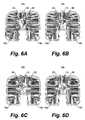
- Figs. 6A-Dschematically illustrate these four discretely selectable rotational positions of the closure member 36, which, for ease of recognition, is provided with a dot-hatch pattern.
- the closure member 36cooperates with the common outlet 22 (and the partition 14) to define large, half-circular outflow openings that are exclusively associated with compartments 18a and 18b, respectively.
- the closure member 36cooperates with the common outlet 22 (and the partition 14) to define two smaller, quarter-circular outflow openings, one of which is associated with compartment 18a, and one of which is associated with compartment 18b.
- the rotational positions of Figs. 6A and 6Bthus allow for the outflow of coffee beans from compartment 18a or compartment 18b, while the rotational positions allow for the concurrent or mixed outflow of coffee beans from both compartment 18a, 18b.
- a usermay turn the control knob 34 counter-clockwise (as seen in the top view of Fig. 6 ). In doing so, he must overcome the spring-bias that forces the toothed members 50a, 50b together in the meshing position that corresponds to the rotational position of the closure member 26 shown in Fig. 6A . If sufficient torque is applied and the spring-bias is overcome, the toothed members 50a, 50b may rotate relative to each other while they are axially forced apart (against the spring-bias).
- This relative rotation of the toothed members 50a, 50bmay continue until the teeth of the respective toothed members are again in meshable rotational registry, at which point the toothed members snap into the meshing position that corresponds to the rotational position of Fig. 6B under the action of the spring force.
- the meshing positions of the toothed members 50a, 50bare all configured to correspond to suitable rotational positions of the closure member 36, as illustrated in Fig. 6 , the risk of selecting unsuitable rotational positions of the closure member is eliminated. Furthermore, the spring-biased interaction between the toothed members 50a, 50b provides for tactile feedback to the user via the control knob 34 to affirm the selection of a suitable rotational position of the closure member. And the spring-biased interaction also advantageously ensures that any meshing position selected by the user and assumed by the two toothed members 50a, 50b is practically locked, and cannot be altered accidentally by vibrations of a grinder.
Landscapes
- Engineering & Computer Science (AREA)
- Mechanical Engineering (AREA)
- Food Science & Technology (AREA)
- Apparatus For Making Beverages (AREA)
Description
- The present invention relates to the field of coffee mills, and more in particular to a multiple-compartment coffee mill hopper suitable for use in a coffee mill.
- UK patent application publication
GB 2,298,148-A DE 594983 discloses a coffee mill hopper assembly according to the preamble ofclaim 1.- A not so obvious drawback of the coffee mill hopper of GB'148 is that it allows a user unlimited flexibility in selecting and setting the rotational position of the control knob. Indeed, it seems to provide advantageously flexible control over the outflow opening through which coffee beans from one or both compartments may flow out of the hopper, and thus over the strength and/or blend ratio of the coffee to be brewed. Some selectable rotational positions of the control knob, however, are preferably avoided, for instance because their corresponding outflow opening sizes are fairly small and likely to cause congestion, or to result in undesirably weak coffee. In addition, the control knob does not provide for any feedback that affirms the selection of a suitable rotational position, which is undesirable from a usability point of view. Furthermore, the rotational position of the cup-shaped closure cannot be fixed. As a result, it may inadvertently change under the vibrating action of the grinder that is attached to the hopper.
- It is an object of the present invention to provide for a coffee mill hopper assembly that overcomes or mitigates the aforementioned issues.
- To this end, a first aspect of the present invention is directed to a coffee mill hopper assembly. The assembly may comprise a hopper defining a plurality of compartments for storing coffee beans, and at least one outlet through which coffee beans from the respective compartments may be released from the hopper. The assembly may also comprise a compartment selector. The compartment selector may include a shaft that interconnects a control knob and a closure member, and that is rotatably mounted to the hopper such that a rotational position of the closure member (relative to the hopper) is adjustable by rotating the shaft around its axis through rotation of the control knob. The closure member may be arranged to cooperate with the at least one outlet of the hopper to provide at least one outflow aperture that, depending on the rotational position of the closure member, selectively enables a release of coffee beans from at least one compartment. The compartment selector may further comprise a first toothed member that is rotationally locked to the shaft, and a second toothed member that is rotationally locked to the hopper. At least one of the toothed members may be movably arranged and be spring-biased to force the teeth of the toothed members towards each other in a meshing relationship.
- The compartment selector of the presently disclosed coffee mill hopper assembly may thus include two toothed members that are both movable relative to each other and spring-biased towards each other. When the compartment selector is free of manual control, the teeth of the toothed members may be forced together into one of a plurality of discrete meshing positions, each of which corresponds to a pre-determined and in itself suitable rotational position of the closure member. Then, when adjustment of the rotational position of the closure member is desired, a user may turn the control knob. In doing so, he must overcome the spring-bias that forces the toothed members together. If sufficient torque is applied and the spring-bias is overcome, the toothed members may rotate relative to each other while they, at at least their meshing teeth, are forced apart (against the spring-bias). This relative rotation of the toothed members may continue until the teeth of the respective toothed members are again in meshable rotational registry, at which point the toothed members snap into another meshing position under the action of the spring force.
- Because the meshing positions of the toothed members may all be configured to correspond to suitable rotational positions of the closure member, the risk of selecting unsuitable rotational positions of the closure member may be eliminated. Furthermore, the spring-biased interaction between the toothed members provides for tactile feedback to the user via the control knob to affirm the selection of a suitable rotational position of the closure member. In addition, the spring-biased interaction also ensures that any meshing position selected by the user and assumed by the two toothed members is practically locked, and cannot be altered accidentally by vibrations of a grinder.
- These and other features and advantages of the invention will be more fully understood from the following detailed description of certain embodiments of the invention, taken together with the accompanying drawings, which are meant to illustrate and not to limit the invention.
Fig. 1 is a schematic top perspective view of an exemplary embodiment of a coffee mill hopper assembly according to the present invention;Fig. 2 is a schematic top perspective view of the coffee mill hopper assembly ofFig. 1 from which the lid of the hopper has been removed, such that the interior coffee bean compartments are visible;Fig. 3 is a schematic bottom perspective view of the coffee mill hopper assembly ofFig. 1 ;Fig. 4 is a schematic partly exploded top perspective view of the coffee mill hopper assembly ofFigs. 1-3 , illustrating the construction of the compartment selector;Fig. 5 is a schematic cross-sectional side view of the coffee mill hopper assembly ofFigs. 1-3 , illustrating the construction of the compartment selector; andFigs. 6A-D is a series of top views of the coffee mill hopper assembly ofFigs. 1-5 , wherein the control knob of the compartment selector has been removed to illustrate the discretely selectable rotational positions of the closure member.Figs. 1-6 schematically illustrate in various views an exemplary embodiment of a coffeemill hopper assembly 1 according to the present invention. Below, the coffee mill hopper assembly according to the present invention will be elucidated in general terms, where appropriate with reference to the embodiment depicted inFigs. 1-6 .- The presently disclosed coffee
mill hopper assembly 1 may comprise ahopper 10. Thehopper 10 may include abottom wall 20, acircumferential side wall 12 that extends in a generally upward, possibly outwardly oblique direction from thebottom wall 20, and a top wall 11 (shown only inFig. 1 ) that meets with theside wall 12 to close off an interior of thehopper 10. Thetop wall 11 may preferably be detachably or hingeably connected to theside wall 12, such that it forms a lid or cover that is easily removable to enable refilling of thehopper 10. Thehopper 10 may further include one ormore partitions 14 that divide the interior of thehopper 10 into a plurality ofcompartments Figs. 1-6 , thehopper 10 includes onepartition 14 that divides the interior of thehopper 10 into twosymmetric compartments hopper 10 may have a different number or configuration of partitions to define more than two compartments, e.g. three or four. - The
bottom wall 20 of thehopper 10 may include at least one outlet or outlet opening 22 through which coffee beans may be released from thecompartments hopper 10. In one embodiment, eachindividual compartment Figs. 1-6 , at least twocompartments common outlet 22 via which coffee beans from (all) the respective at least two compartments may be released. In such an embodiment, thecommon outlet 22 may typically be arranged in thebottom wall 20 and extend below/underneath the partition(s) 14 that separate(s) thecompartments common outlet 22. As in the depicted embodiment, thebottom wall 20 may slope downwardly towards the at least oneoutlet 22, so as to bias the coffee beans towards it. The inner surface of thebottom wall 20 may also be provided with a plurality of ridges orribs 21 to prevent coffee beans from sticking to thebottom wall 20, and thus to promote the outflow/release of coffee beans from thecompartments - The coffee
mill hopper assembly 1 may further include acompartment selector 30. - The
compartment selector 30 may include ashaft 32. Theshaft 32 may be bearing mounted to thehopper 10 such that it is rotatable around its longitudinal axis L. In the depicted embodiment, thepartition 14 of thehopper 10 defines a bushing ortube 15 that is dimensioned to receive theshaft 32 in a plain bearing arrangement, wherein an inner surface of thebushing 15 provides for a bearing surface and an outer surface of the shaft slides over the bearing surface when theshaft 32 is rotated. Although the plain bearing arrangement is simple and economical, it is understood that different types of bearings, such as rolling-element bearings, may alternatively be used to rotatably mount theshaft 32 to thehopper 10. - At its upper end, the
shaft 32 may be operably connected to arotatable knob 34. Theknob 34 may preferably be at least partially arranged at an outside of the coffeemill hopper assembly 1, such that it is manually accessible during operation. - At its lower end the
shaft 32 may connect to aclosure member 36 that is configured to cooperate with the at least onecoffee bean outlet 22 of thehopper 10, such that it wholly or partly closes off the at least oneoutlet 22 depending on the rotational position of theshaft 32. In the depicted embodiment, theclosure member 36 is shaped as an inverted cup of which 180° is absent. The inverted cup has an outer diameter that matches an inner diameter of thecommon outlet 22 in which it is arranged. An upper or top side of the cup-shapedclosure member 36, which connects to theshaft 32, is slightly slanted downwards to direct coffee beans away from the central axis L of theshaft 32, and to ensure that the upper side does not form a ledge on which coffee beans can rest. A radially inner portion of the slanted upper side of theclosure member 36 may smoothly bear against the correspondingly tapered lower circumferential edge of thebushing 15. - It is contemplated that the
closure member 36 may take different forms in alternative embodiments. In an embodiment having ahopper 10 withn compartments 18 that are rotationally symmetrically arranged around and share acommon outlet 22, for example, an absent angular part of a cup-shapedclosure member 36 may generally cover (360/n)°. Accordingly, thecompartment selector 30 for ahopper 10 whose interior is divided into three compartments may include an inverted cup-shaped closure member of which (360°/3=) 120° is absent. Furthermore, theclosure member 36 need not be inverted cup-shaped. In one embodiment, for instance, the closure member may include a planar disc that abuts the portion of the bottom wall 18 comprising the at least oneoutlet 22, and that defines one or more openings that may wholly or partly register with the at least oneoutlet 22 depending on the rotational position of theshaft 32. - The
compartment selector 30 may further include twotoothed members - A first 50a of the toothed members may be rotationally locked to the
shaft 32, such that it rotates in unison therewith. A second of thetoothed members 50b may be rotationally locked to thehopper 10, such that it rotates in unison with thehopper 10. For the purpose of the present invention, however, thehopper 10 may be regarded stationary, which means that the secondtoothed member 50b - and its teeth - may be considered rotationally fixed relative to the axis of rotationL of theshaft 32. Furthermore, at least one of thetoothed members shaft 32. In one embodiment (such as the depicted embodiment) the at least one movably arranged toothed member may be movably arranged along/parallel to the axisL of theshaft 32. In another embodiment, the at least one movably arranged toothed member may be movably arranged in a radial direction relative to the axisL as of theshaft 32. The twotoothed members respective teeth toothed member teeth toothed members - To facilitate the desired interaction between the
teeth toothed members toothed members - As mentioned, both toothed
members tooth toothed members toothed members hopper compartments toothed members closure member 36. These2n rotational positions of theclosure member 36 may advantageously allow for the selection of eachindividual compartment toothed member teeth - The
teeth toothed member teeth 54a on the firsttoothed member 50a may but need not have a same shape as theteeth 54b on the secondtoothed member 50b. Therespective teeth 54a, 54 may, however, preferably be complementarily shaped to enable a mutually fitting engagement. - In the depicted exemplary coffee
mill hopper assembly 1, the above-described general principles are embodied as follows. - Each of the
toothed members annular base member shaft 32. The separate nature and annular shape of thetoothed members compartment selector 30, but are no necessity. In a variation of the depicted embodiment, for example, the firsttoothed member 50a may be integrally formed with theshaft 32. - The first
toothed member 50a defines two identical downwardly pointing wedge-shapedteeth 54a, which are diametrically arranged on a lower side of the firstannular base member 52a. The secondtoothed member 50b defines four identical upwardly pointing wedge-shapedteeth 54b, which are arranged on an upper side of the secondannular base member 52b in an equidistantly spaced apart fashion. Theteeth first tooth 54a neatly fits in between each two circumferentially adjacentsecond teeth 54b. - To properly mount the various parts of the
compartment selector 30 to thehopper 10, aguide member 40 is provided. Theguide member 40 includes two coaxially arranged cylindrical or cylinder jacket-shaped walls, which are connected at their lower ends by abottom wall 46, and spaced apart to define an annular, axially extendingspace 41 between them. Thebottom wall 46 and the inner cylindrical wall of the guide member together define a radially-stepped axially extending bore, the lower and wider part of which is configured to receive the top end of thebushing 15 of thepartition 14, such that theguide member 40 can be coaxially mounted on top of the bushing 15 (best seen inFig. 5 ). Thepartition 14 further defines twoelongate slots 16 on either side of thebushing 15 to allow theguide member 40 to be slid over it (best seen inFig. 4 ). Two straight and axially extendingguide grooves 42, diametrically arranged on an outside of the outer cylindrical wall of theguide member 40, cooperate with elongate axially extendingedges 17 of theslots 16 to facilitate the installation of theguide member 40 during assembly, and to rotationally lock theguide member 40 to thehopper 10. On an inside of the outer cylindrical wall of theguide member 40, four straight, axially extendingguide ribs 44 are provided at 90°-intervals around the axis L. Corresponding recesses 56 for reception of theguide ribs 44 are provided in an outer circumferential edge of theannular base member 52b of the secondtoothed member 50b. - The first
toothed member 50a is fixedly connected to theshaft 32 at a point just above the top end of the inner cylindrical wall of the guide member 40 (which inner wall forms an extension of the bushing 15), with itsteeth 54a pointing downwards. A radially inner portion of a lower side of theannular base member 52a of the firsttoothed member 50a smoothly bears against an upper circumferential edge of the inner cylindrical wall of theguide member 40, and thus cooperates with the radially inner portion of the upper side of the inverted cup-shapedclosure member 36 bearing against the lower circumferential edge of thebushing 15 to axially fix theshaft 32 in thebushing 15. - The second
toothed member 50b is rotationally locked to thehopper 10 while being slidably movable along the central axisL of theshaft 32. To this end, it is snugly arranged inside theannular space 41 between the cylindrical walls of theguide member 40, such that therecesses 56 in the outer circumferential edge of itsannular member 52b receive and engage theguide ribs 44 on the inside of theguide member 40. Acoil spring 38, disposed between a lower side of the secondtoothed member 50b and thebottom wall 46 theguide member 40, serves to urge or bias the secondtoothed member 50b upwards along the axis L, into contact with the firsttoothed member 50a. At its lower end, theguide member 40 may be provided with one ormore wings 48, typically one perhopper compartment wing 48 may extend radially outwards at a downward slope, and so help to direct coffee beans away from the central axis L and 'around' theclosure member 36 in order to promote their smooth outflow through theoutlet 22. Except for thespring 38, which may preferably be made of metal, the parts of the coffeemill hopper assembly 1 may be economically manufactured from plastic, for instance through injection molding. - Now that the construction of the coffee mill hopper assembly of the present invention has been described in some detail, attention is invited to its operation.
- When the
compartment selector 30 of the depicted coffeemill hopper assembly 1 is free of manual control, the teeth of thetoothed members spring 38 into one of four discrete meshing positions. Each of these meshing positions corresponds to a pre-determined and in itself suitable rotational position of theclosure member 36.Figs. 6A-D schematically illustrate these four discretely selectable rotational positions of theclosure member 36, which, for ease of recognition, is provided with a dot-hatch pattern. In the position ofFig. 6A and 6B , theclosure member 36 cooperates with the common outlet 22 (and the partition 14) to define large, half-circular outflow openings that are exclusively associated withcompartments Figs. 6C and 6D , on the other hand, theclosure member 36 cooperates with the common outlet 22 (and the partition 14) to define two smaller, quarter-circular outflow openings, one of which is associated withcompartment 18a, and one of which is associated withcompartment 18b. The rotational positions ofFigs. 6A and 6B thus allow for the outflow of coffee beans fromcompartment 18a orcompartment 18b, while the rotational positions allow for the concurrent or mixed outflow of coffee beans from bothcompartment - When adjustment of the rotational position of the
closure member 36 is desired, for instance a change of its position from that ofFig. 6A to that ofFig. 6B , a user may turn thecontrol knob 34 counter-clockwise (as seen in the top view ofFig. 6 ). In doing so, he must overcome the spring-bias that forces thetoothed members Fig. 6A . If sufficient torque is applied and the spring-bias is overcome, thetoothed members toothed members Fig. 6B under the action of the spring force. - Because the meshing positions of the
toothed members closure member 36, as illustrated inFig. 6 , the risk of selecting unsuitable rotational positions of the closure member is eliminated. Furthermore, the spring-biased interaction between thetoothed members control knob 34 to affirm the selection of a suitable rotational position of the closure member. And the spring-biased interaction also advantageously ensures that any meshing position selected by the user and assumed by the twotoothed members - Although illustrative embodiments of the present invention have been described above, in part with reference to the accompanying drawings, it is to be understood that the invention is not limited to these embodiments. Variations to the disclosed embodiments can be understood and effected by those skilled in the art in practicing the claimed invention, from a study of the drawings, the disclosure, and the appended claims. Reference throughout this specification to "one embodiment" or "an embodiment" means that a particular feature, structure or characteristic described in connection with the embodiment is included in at least one embodiment of the present invention. Thus, the appearances of the phrases "in one embodiment" or "in an embodiment" in various places throughout this specification are not necessarily all referring to the same embodiment. Furthermore, it is noted that particular features, structures, or characteristics of one or more embodiments may be combined in any suitable manner to form new, not explicitly described embodiments.
Claims (12)
- A coffee mill hopper assembly (1), comprising:a hopper (10) defining a plurality of compartments (18a, 18b) for storing coffee beans, and at least one outlet (22) through which coffee beans may be released from the respective compartments of the hopper;a compartment selector (30), comprising a shaft (32) interconnecting a control knob (34) and a closure member (36), said shaft being rotatably mounted to the hopper (10) such that a rotational position of the closure member is adjustable by rotating the shaft around its axis (L) through rotation of the control knob, and wherein the closure member (36) is arranged to cooperate with the at least one outlet (22) of the hopper to provide at least one outflow aperture that, depending on the rotational position of the closure member, selectively enables a release of coffee beans from at least one compartment (18a, 18b);characterized in that the compartment selector (30) further comprises a first toothed member (50a) that is rotationally locked to the shaft (32) and a second toothed member (50b) that is rotationally locked to the hopper (10), at least one of said toothed members (50a, 50b) being movably arranged relative to the shaft (32) and spring-biased to force the teeth (54a, 54b) of the toothed members towards each other in a meshing relationship.
- The coffee mill hopper assembly according to claim 1, wherein at least one of the first and second toothed members (50a, 50b) comprises a plurality of teeth that are substantially identical and equidistantly spaced apart in a circumferential direction around the axis (L) of the shaft (32).
- The coffee mill hopper assembly according to any of the claims 1-2, wherein one of said toothed members (50a, 50b) has2n teeth (54a, 54b),n being the number of compartments (18a, 18b), while the other of said toothed members (50a, 50b) has a number of teeth that is equal to or less than2n.
- The coffee mill hopper assembly according to any of the claims 1-3, wherein the two toothed members (50a, 50b) define at least three meshing positions, wherein:in a first meshing position, the closure member (36) cooperates with the at least one outlet (22) of the hopper (10) to provide at least one outflow aperture that enables a release of coffee beans exclusively from a first of said compartments (18a);in a second meshing position, the closure member (36) cooperates with the at least one outlet (22) of the hopper (10) to provide at least one outflow aperture that enables a release of coffee beans exclusively from a second of said compartments (18b); andin a third meshing position, the closure member (36) cooperates with the at least one outlet (22) of the hopper (10) to provide at least one outflow aperture that enables a concurrent release of coffee beans from both the first and the second of said compartments (18a, 18b).
- The coffee mill hopper assembly according to any of the claims 1-4, wherein said at least one movably arranged toothed member (50b) is movably arranged in a radial direction relative to the axis (L) of the shaft (32).
- The coffee mill hopper assembly according to any of the claims 1-4, wherein said at least one movably arranged toothed member (50b) is movably arranged in a direction parallel to the axis (L) of the shaft (32).
- The coffee mill hopper assembly according to any of the claims 1-6, wherein the first toothed member (50a) is fixedly attached to the shaft (32).
- The coffee mill hopper assembly according to any of the claims 6-7, wherein the second toothed member (50b) includes an annular base member (52b) that is coaxially arranged with the shaft (32), and movable along the axial direction (L) thereof.
- The coffee mill hopper assembly according to any of the claims 1-8, wherein the compartment selector (36) includes a coil spring (38) that is arranged coaxially with the shaft (32), and that urges the second toothed member (50b) towards the first toothed member (50a).
- The coffee mill hopper assembly according to any of the claims 1-9, wherein the plurality of compartments (18a, 18b) share a common outlet (22), and
wherein the closure member (36) is arranged to cooperate with the common outlet. - A coffee mill, comprising:a coffee mill hopper assembly (1) according to any of the claims 1-10; andgrinding means that are operably connected to the coffee mill hopper assembly (1), and configured to grind coffee beans released from the hopper through the at least one outlet (22) thereof.
- A coffee machine, comprising a coffee mill according to claim 11.
Priority Applications (1)
| Application Number | Priority Date | Filing Date | Title |
|---|---|---|---|
| EP14727058.1AEP2994027B1 (en) | 2013-05-08 | 2014-04-30 | Multiple-compartment coffee mill hopper for a coffee mill |
Applications Claiming Priority (4)
| Application Number | Priority Date | Filing Date | Title |
|---|---|---|---|
| EP13167135 | 2013-05-08 | ||
| EP13168248 | 2013-05-17 | ||
| PCT/IB2014/061112WO2014181225A1 (en) | 2013-05-08 | 2014-04-30 | Multiple-compartment coffee mill hopper for a coffee mill |
| EP14727058.1AEP2994027B1 (en) | 2013-05-08 | 2014-04-30 | Multiple-compartment coffee mill hopper for a coffee mill |
Publications (2)
| Publication Number | Publication Date |
|---|---|
| EP2994027A1 EP2994027A1 (en) | 2016-03-16 |
| EP2994027B1true EP2994027B1 (en) | 2016-11-16 |
Family
ID=50677959
Family Applications (2)
| Application Number | Title | Priority Date | Filing Date |
|---|---|---|---|
| EP14166501.8ANot-in-forceEP2801307B1 (en) | 2013-05-08 | 2014-04-30 | Multiple-compartment coffee mill hopper for a coffee mill |
| EP14727058.1AActiveEP2994027B1 (en) | 2013-05-08 | 2014-04-30 | Multiple-compartment coffee mill hopper for a coffee mill |
Family Applications Before (1)
| Application Number | Title | Priority Date | Filing Date |
|---|---|---|---|
| EP14166501.8ANot-in-forceEP2801307B1 (en) | 2013-05-08 | 2014-04-30 | Multiple-compartment coffee mill hopper for a coffee mill |
Country Status (7)
| Country | Link |
|---|---|
| US (1) | US9848736B2 (en) |
| EP (2) | EP2801307B1 (en) |
| JP (1) | JP5947995B1 (en) |
| CN (1) | CN105188492B (en) |
| BR (1) | BR112015027800A2 (en) |
| RU (1) | RU2643342C2 (en) |
| WO (1) | WO2014181225A1 (en) |
Families Citing this family (10)
| Publication number | Priority date | Publication date | Assignee | Title |
|---|---|---|---|---|
| WO2015077237A2 (en)* | 2013-11-20 | 2015-05-28 | Starbucks Corporation D/B/A Starbucks Coffee Company | Cooking system power management |
| DE102014107647B4 (en)* | 2014-05-30 | 2017-01-05 | Eugster/Frismag Ag | Coffee bean container |
| EP3328251B1 (en)* | 2015-07-30 | 2020-05-13 | Koninklijke Philips N.V. | Selector unit and coffee machine |
| EP3135160A1 (en)* | 2015-08-31 | 2017-03-01 | Bernd Müller | Coffee bean supply device, coffee brewing apparatus and coffee brewing process making use of the device |
| FR3042397B1 (en)* | 2015-10-15 | 2017-11-03 | Seb Sa | DEVICE FOR DISPENSING DOUBLE-OUTLED BEVERAGES AND COFFEE MACHINE COMPRISING SUCH A DEVICE |
| DE102016105702A1 (en)* | 2016-03-29 | 2017-10-05 | Melitta Europa Gmbh & Co. Kg | coffee machine |
| DE102021104467A1 (en) | 2021-02-25 | 2022-08-25 | Miele & Cie. Kg | coffee machine |
| USD1044404S1 (en)* | 2022-01-18 | 2024-10-01 | Bernd Braune | Component of a non-electric coffee grinder |
| US12369744B1 (en) | 2024-01-18 | 2025-07-29 | Sharkninja Operating Llc | Preparation of beverage machines for cold beverage brewing |
| WO2025155323A1 (en) | 2024-01-18 | 2025-07-24 | Sharkninja Operating Llc | Preventing coffee bean grinder jamming |
Family Cites Families (12)
| Publication number | Priority date | Publication date | Assignee | Title |
|---|---|---|---|---|
| DE451326C (en) | 1926-07-21 | 1927-10-25 | Alfred Koch | Partition for storage containers connected to coffee grinders |
| DE594983C (en) | 1933-01-25 | 1934-03-26 | Ernst Lind | Divided storage container for wall coffee grinders |
| US5186399A (en) | 1988-08-01 | 1993-02-16 | Bunn-O-Matic Corporation | Digital control system for a coffee grinder and associated coffee brewer |
| USRE34382E (en)* | 1989-04-20 | 1993-09-21 | Grindmaster Corporation | Bean and ground coffee carrier member for use in coffee systems |
| US5458295A (en)* | 1994-09-02 | 1995-10-17 | Haber; Barry M. | Dual chamber coffee mill |
| CH690609A5 (en)* | 1995-02-21 | 2000-11-15 | Chiaphua Ind Ltd | Hopper for coffee mill |
| GB2298148B (en) | 1995-02-21 | 1998-03-18 | Chiaphua Ind Ltd | Coffee mill |
| US5697528A (en)* | 1995-06-19 | 1997-12-16 | Conair Corporation | Coffee mill adapted for controlled mixing of coffee beans |
| US5950245A (en)* | 1997-04-14 | 1999-09-14 | Mine Safety Appliances Company | Adjustable headband with a ratchet mechanism having different resistances |
| DE10300481A1 (en)* | 2003-01-08 | 2004-07-22 | Y-Design Gmbh | Supply container for coffee grinder has two or more different chambers to hold different types of coffee with outlet openings for selectively supplying grinder |
| CN2703945Y (en)* | 2004-06-16 | 2005-06-08 | 谢建勇 | Sun-shading awning angle regulating device |
| US7607386B2 (en)* | 2004-12-27 | 2009-10-27 | Lorielle Wise | System for simultaneously brewing and dispensing multiple beverages or any variation thereof from a single unitary structure |
- 2014
- 2014-04-30EPEP14166501.8Apatent/EP2801307B1/ennot_activeNot-in-force
- 2014-04-30CNCN201480025746.6Apatent/CN105188492B/enactiveActive
- 2014-04-30BRBR112015027800Apatent/BR112015027800A2/ennot_activeApplication Discontinuation
- 2014-04-30USUS14/888,783patent/US9848736B2/enactiveActive
- 2014-04-30EPEP14727058.1Apatent/EP2994027B1/enactiveActive
- 2014-04-30WOPCT/IB2014/061112patent/WO2014181225A1/enactiveApplication Filing
- 2014-04-30RURU2015152428Apatent/RU2643342C2/enactive
- 2014-04-30JPJP2016511158Apatent/JP5947995B1/enactiveActive
Also Published As
| Publication number | Publication date |
|---|---|
| BR112015027800A2 (en) | 2020-03-10 |
| CN105188492A (en) | 2015-12-23 |
| EP2801307A1 (en) | 2014-11-12 |
| WO2014181225A1 (en) | 2014-11-13 |
| JP5947995B1 (en) | 2016-07-06 |
| EP2801307B1 (en) | 2016-11-16 |
| RU2643342C2 (en) | 2018-01-31 |
| US20160073825A1 (en) | 2016-03-17 |
| EP2994027A1 (en) | 2016-03-16 |
| CN105188492B (en) | 2018-10-09 |
| US9848736B2 (en) | 2017-12-26 |
| JP2016522025A (en) | 2016-07-28 |
| RU2015152428A (en) | 2017-06-14 |
Similar Documents
| Publication | Publication Date | Title |
|---|---|---|
| EP2801307B1 (en) | Multiple-compartment coffee mill hopper for a coffee mill | |
| AU2011276459B2 (en) | Adjustable grinder and a stator for the adjustable grinder | |
| CA2688497C (en) | Adjustable grinder | |
| US7878437B2 (en) | Canister with adjustable grinder | |
| US20150272394A1 (en) | Blender | |
| CN106413490B (en) | Grinding device for energy abrasive product | |
| AU2019297207B2 (en) | Foodstuff processing system | |
| KR930016065A (en) | Spice Grinder | |
| EP2096969B1 (en) | Spice grinders | |
| US20080315021A1 (en) | Adjustable Condiment Grinder | |
| WO2016046560A2 (en) | Fluid control valves | |
| AU2011336239A1 (en) | Spice grinders | |
| CN105473041B (en) | Cooking and preparation appliance comprising a work implement detachably engaged on a drive | |
| US20120103986A1 (en) | Powder Container That Will Prevent A User's Hand From Touching The Powder Directly | |
| EP2047781B1 (en) | Pepper mill | |
| JP2022553925A (en) | Hopper for coffee grinder with lower closing device for saving coffee beans and coffee grinder with said hopper | |
| US11209042B2 (en) | Pivot fitting and piece of furniture | |
| US20090078807A1 (en) | Adjustable grinder | |
| GB2450161A (en) | Adjustable condiment grinder | |
| EP3346893B1 (en) | Seasoning mill | |
| GB2452966A (en) | Condiment grinder having adjustor knob to adjust the space between the grinding elements | |
| MXPA96005013A (en) | Be. HINGE OF MULTIPLE POSITIONS FOR S AND CAPS OF INODO |
Legal Events
| Date | Code | Title | Description |
|---|---|---|---|
| PUAI | Public reference made under article 153(3) epc to a published international application that has entered the european phase | Free format text:ORIGINAL CODE: 0009012 | |
| 17P | Request for examination filed | Effective date:20151208 | |
| AK | Designated contracting states | Kind code of ref document:A1 Designated state(s):AL AT BE BG CH CY CZ DE DK EE ES FI FR GB GR HR HU IE IS IT LI LT LU LV MC MK MT NL NO PL PT RO RS SE SI SK SM TR | |
| AX | Request for extension of the european patent | Extension state:BA ME | |
| GRAP | Despatch of communication of intention to grant a patent | Free format text:ORIGINAL CODE: EPIDOSNIGR1 | |
| RIC1 | Information provided on ipc code assigned before grant | Ipc:B65D 83/00 20060101ALI20160527BHEP Ipc:A47J 31/50 20060101AFI20160527BHEP Ipc:A47J 42/50 20060101ALI20160527BHEP | |
| DAX | Request for extension of the european patent (deleted) | ||
| INTG | Intention to grant announced | Effective date:20160613 | |
| GRAS | Grant fee paid | Free format text:ORIGINAL CODE: EPIDOSNIGR3 | |
| GRAA | (expected) grant | Free format text:ORIGINAL CODE: 0009210 | |
| AK | Designated contracting states | Kind code of ref document:B1 Designated state(s):AL AT BE BG CH CY CZ DE DK EE ES FI FR GB GR HR HU IE IS IT LI LT LU LV MC MK MT NL NO PL PT RO RS SE SI SK SM TR | |
| REG | Reference to a national code | Ref country code:GB Ref legal event code:FG4D | |
| REG | Reference to a national code | Ref country code:CH Ref legal event code:EP | |
| REG | Reference to a national code | Ref country code:IE Ref legal event code:FG4D | |
| REG | Reference to a national code | Ref country code:AT Ref legal event code:REF Ref document number:845060 Country of ref document:AT Kind code of ref document:T Effective date:20161215 | |
| REG | Reference to a national code | Ref country code:DE Ref legal event code:R096 Ref document number:602014004935 Country of ref document:DE | |
| PG25 | Lapsed in a contracting state [announced via postgrant information from national office to epo] | Ref country code:LV Free format text:LAPSE BECAUSE OF FAILURE TO SUBMIT A TRANSLATION OF THE DESCRIPTION OR TO PAY THE FEE WITHIN THE PRESCRIBED TIME-LIMIT Effective date:20161116 | |
| REG | Reference to a national code | Ref country code:NL Ref legal event code:MP Effective date:20161116 | |
| REG | Reference to a national code | Ref country code:LT Ref legal event code:MG4D | |
| REG | Reference to a national code | Ref country code:AT Ref legal event code:MK05 Ref document number:845060 Country of ref document:AT Kind code of ref document:T Effective date:20161116 | |
| PG25 | Lapsed in a contracting state [announced via postgrant information from national office to epo] | Ref country code:NL Free format text:LAPSE BECAUSE OF FAILURE TO SUBMIT A TRANSLATION OF THE DESCRIPTION OR TO PAY THE FEE WITHIN THE PRESCRIBED TIME-LIMIT Effective date:20161116 Ref country code:GR Free format text:LAPSE BECAUSE OF FAILURE TO SUBMIT A TRANSLATION OF THE DESCRIPTION OR TO PAY THE FEE WITHIN THE PRESCRIBED TIME-LIMIT Effective date:20170217 Ref country code:SE Free format text:LAPSE BECAUSE OF FAILURE TO SUBMIT A TRANSLATION OF THE DESCRIPTION OR TO PAY THE FEE WITHIN THE PRESCRIBED TIME-LIMIT Effective date:20161116 Ref country code:LT Free format text:LAPSE BECAUSE OF FAILURE TO SUBMIT A TRANSLATION OF THE DESCRIPTION OR TO PAY THE FEE WITHIN THE PRESCRIBED TIME-LIMIT Effective date:20161116 Ref country code:NO Free format text:LAPSE BECAUSE OF FAILURE TO SUBMIT A TRANSLATION OF THE DESCRIPTION OR TO PAY THE FEE WITHIN THE PRESCRIBED TIME-LIMIT Effective date:20170216 | |
| REG | Reference to a national code | Ref country code:FR Ref legal event code:PLFP Year of fee payment:4 | |
| PG25 | Lapsed in a contracting state [announced via postgrant information from national office to epo] | Ref country code:PT Free format text:LAPSE BECAUSE OF FAILURE TO SUBMIT A TRANSLATION OF THE DESCRIPTION OR TO PAY THE FEE WITHIN THE PRESCRIBED TIME-LIMIT Effective date:20170316 Ref country code:ES Free format text:LAPSE BECAUSE OF FAILURE TO SUBMIT A TRANSLATION OF THE DESCRIPTION OR TO PAY THE FEE WITHIN THE PRESCRIBED TIME-LIMIT Effective date:20161116 Ref country code:PL Free format text:LAPSE BECAUSE OF FAILURE TO SUBMIT A TRANSLATION OF THE DESCRIPTION OR TO PAY THE FEE WITHIN THE PRESCRIBED TIME-LIMIT Effective date:20161116 Ref country code:FI Free format text:LAPSE BECAUSE OF FAILURE TO SUBMIT A TRANSLATION OF THE DESCRIPTION OR TO PAY THE FEE WITHIN THE PRESCRIBED TIME-LIMIT Effective date:20161116 Ref country code:RS Free format text:LAPSE BECAUSE OF FAILURE TO SUBMIT A TRANSLATION OF THE DESCRIPTION OR TO PAY THE FEE WITHIN THE PRESCRIBED TIME-LIMIT Effective date:20161116 Ref country code:AT Free format text:LAPSE BECAUSE OF FAILURE TO SUBMIT A TRANSLATION OF THE DESCRIPTION OR TO PAY THE FEE WITHIN THE PRESCRIBED TIME-LIMIT Effective date:20161116 Ref country code:HR Free format text:LAPSE BECAUSE OF FAILURE TO SUBMIT A TRANSLATION OF THE DESCRIPTION OR TO PAY THE FEE WITHIN THE PRESCRIBED TIME-LIMIT Effective date:20161116 | |
| PG25 | Lapsed in a contracting state [announced via postgrant information from national office to epo] | Ref country code:EE Free format text:LAPSE BECAUSE OF FAILURE TO SUBMIT A TRANSLATION OF THE DESCRIPTION OR TO PAY THE FEE WITHIN THE PRESCRIBED TIME-LIMIT Effective date:20161116 Ref country code:SK Free format text:LAPSE BECAUSE OF FAILURE TO SUBMIT A TRANSLATION OF THE DESCRIPTION OR TO PAY THE FEE WITHIN THE PRESCRIBED TIME-LIMIT Effective date:20161116 Ref country code:CZ Free format text:LAPSE BECAUSE OF FAILURE TO SUBMIT A TRANSLATION OF THE DESCRIPTION OR TO PAY THE FEE WITHIN THE PRESCRIBED TIME-LIMIT Effective date:20161116 Ref country code:DK Free format text:LAPSE BECAUSE OF FAILURE TO SUBMIT A TRANSLATION OF THE DESCRIPTION OR TO PAY THE FEE WITHIN THE PRESCRIBED TIME-LIMIT Effective date:20161116 Ref country code:RO Free format text:LAPSE BECAUSE OF FAILURE TO SUBMIT A TRANSLATION OF THE DESCRIPTION OR TO PAY THE FEE WITHIN THE PRESCRIBED TIME-LIMIT Effective date:20161116 | |
| REG | Reference to a national code | Ref country code:DE Ref legal event code:R097 Ref document number:602014004935 Country of ref document:DE | |
| PG25 | Lapsed in a contracting state [announced via postgrant information from national office to epo] | Ref country code:SM Free format text:LAPSE BECAUSE OF FAILURE TO SUBMIT A TRANSLATION OF THE DESCRIPTION OR TO PAY THE FEE WITHIN THE PRESCRIBED TIME-LIMIT Effective date:20161116 Ref country code:IT Free format text:LAPSE BECAUSE OF FAILURE TO SUBMIT A TRANSLATION OF THE DESCRIPTION OR TO PAY THE FEE WITHIN THE PRESCRIBED TIME-LIMIT Effective date:20161116 Ref country code:BG Free format text:LAPSE BECAUSE OF FAILURE TO SUBMIT A TRANSLATION OF THE DESCRIPTION OR TO PAY THE FEE WITHIN THE PRESCRIBED TIME-LIMIT Effective date:20170216 Ref country code:BE Free format text:LAPSE BECAUSE OF FAILURE TO SUBMIT A TRANSLATION OF THE DESCRIPTION OR TO PAY THE FEE WITHIN THE PRESCRIBED TIME-LIMIT Effective date:20161116 | |
| PLBE | No opposition filed within time limit | Free format text:ORIGINAL CODE: 0009261 | |
| STAA | Information on the status of an ep patent application or granted ep patent | Free format text:STATUS: NO OPPOSITION FILED WITHIN TIME LIMIT | |
| 26N | No opposition filed | Effective date:20170817 | |
| PG25 | Lapsed in a contracting state [announced via postgrant information from national office to epo] | Ref country code:SI Free format text:LAPSE BECAUSE OF FAILURE TO SUBMIT A TRANSLATION OF THE DESCRIPTION OR TO PAY THE FEE WITHIN THE PRESCRIBED TIME-LIMIT Effective date:20161116 | |
| REG | Reference to a national code | Ref country code:CH Ref legal event code:PL | |
| REG | Reference to a national code | Ref country code:IE Ref legal event code:MM4A | |
| PG25 | Lapsed in a contracting state [announced via postgrant information from national office to epo] | Ref country code:MC Free format text:LAPSE BECAUSE OF FAILURE TO SUBMIT A TRANSLATION OF THE DESCRIPTION OR TO PAY THE FEE WITHIN THE PRESCRIBED TIME-LIMIT Effective date:20161116 | |
| PG25 | Lapsed in a contracting state [announced via postgrant information from national office to epo] | Ref country code:LI Free format text:LAPSE BECAUSE OF NON-PAYMENT OF DUE FEES Effective date:20170430 Ref country code:LU Free format text:LAPSE BECAUSE OF NON-PAYMENT OF DUE FEES Effective date:20170430 Ref country code:CH Free format text:LAPSE BECAUSE OF NON-PAYMENT OF DUE FEES Effective date:20170430 | |
| PG25 | Lapsed in a contracting state [announced via postgrant information from national office to epo] | Ref country code:IE Free format text:LAPSE BECAUSE OF NON-PAYMENT OF DUE FEES Effective date:20170430 | |
| REG | Reference to a national code | Ref country code:FR Ref legal event code:PLFP Year of fee payment:5 | |
| PG25 | Lapsed in a contracting state [announced via postgrant information from national office to epo] | Ref country code:MT Free format text:LAPSE BECAUSE OF NON-PAYMENT OF DUE FEES Effective date:20170430 | |
| PG25 | Lapsed in a contracting state [announced via postgrant information from national office to epo] | Ref country code:HU Free format text:LAPSE BECAUSE OF FAILURE TO SUBMIT A TRANSLATION OF THE DESCRIPTION OR TO PAY THE FEE WITHIN THE PRESCRIBED TIME-LIMIT; INVALID AB INITIO Effective date:20140430 | |
| PG25 | Lapsed in a contracting state [announced via postgrant information from national office to epo] | Ref country code:CY Free format text:LAPSE BECAUSE OF FAILURE TO SUBMIT A TRANSLATION OF THE DESCRIPTION OR TO PAY THE FEE WITHIN THE PRESCRIBED TIME-LIMIT Effective date:20161116 | |
| PG25 | Lapsed in a contracting state [announced via postgrant information from national office to epo] | Ref country code:MK Free format text:LAPSE BECAUSE OF FAILURE TO SUBMIT A TRANSLATION OF THE DESCRIPTION OR TO PAY THE FEE WITHIN THE PRESCRIBED TIME-LIMIT Effective date:20161116 | |
| PG25 | Lapsed in a contracting state [announced via postgrant information from national office to epo] | Ref country code:AL Free format text:LAPSE BECAUSE OF FAILURE TO SUBMIT A TRANSLATION OF THE DESCRIPTION OR TO PAY THE FEE WITHIN THE PRESCRIBED TIME-LIMIT Effective date:20161116 Ref country code:IS Free format text:LAPSE BECAUSE OF FAILURE TO SUBMIT A TRANSLATION OF THE DESCRIPTION OR TO PAY THE FEE WITHIN THE PRESCRIBED TIME-LIMIT Effective date:20170316 | |
| P01 | Opt-out of the competence of the unified patent court (upc) registered | Effective date:20230530 | |
| REG | Reference to a national code | Ref country code:DE Ref legal event code:R081 Ref document number:602014004935 Country of ref document:DE Owner name:VERSUNI HOLDING B.V., NL Free format text:FORMER OWNER: KONINKLIJKE PHILIPS N.V., EINDHOVEN, NL | |
| REG | Reference to a national code | Ref country code:GB Ref legal event code:732E Free format text:REGISTERED BETWEEN 20231214 AND 20231220 | |
| PGFP | Annual fee paid to national office [announced via postgrant information from national office to epo] | Ref country code:DE Payment date:20250428 Year of fee payment:12 | |
| PGFP | Annual fee paid to national office [announced via postgrant information from national office to epo] | Ref country code:GB Payment date:20250422 Year of fee payment:12 | |
| PGFP | Annual fee paid to national office [announced via postgrant information from national office to epo] | Ref country code:FR Payment date:20250424 Year of fee payment:12 | |
| PGFP | Annual fee paid to national office [announced via postgrant information from national office to epo] | Ref country code:TR Payment date:20250418 Year of fee payment:12 |