EP2993495B1 - Vehicle-mounted inspection system - Google Patents
Vehicle-mounted inspection systemDownload PDFInfo
- Publication number
- EP2993495B1 EP2993495B1EP15183367.0AEP15183367AEP2993495B1EP 2993495 B1EP2993495 B1EP 2993495B1EP 15183367 AEP15183367 AEP 15183367AEP 2993495 B1EP2993495 B1EP 2993495B1
- Authority
- EP
- European Patent Office
- Prior art keywords
- ray
- vehicle
- rotation mechanism
- emission device
- inspection system
- Prior art date
- Legal status (The legal status is an assumption and is not a legal conclusion. Google has not performed a legal analysis and makes no representation as to the accuracy of the status listed.)
- Active
Links
Images


Classifications
- G—PHYSICS
- G01—MEASURING; TESTING
- G01V—GEOPHYSICS; GRAVITATIONAL MEASUREMENTS; DETECTING MASSES OR OBJECTS; TAGS
- G01V5/00—Prospecting or detecting by the use of ionising radiation, e.g. of natural or induced radioactivity
- G01V5/20—Detecting prohibited goods, e.g. weapons, explosives, hazardous substances, contraband or smuggled objects
- G01V5/22—Active interrogation, i.e. by irradiating objects or goods using external radiation sources, e.g. using gamma rays or cosmic rays
- G01V5/232—Active interrogation, i.e. by irradiating objects or goods using external radiation sources, e.g. using gamma rays or cosmic rays having relative motion between the source, detector and object other than by conveyor
- G—PHYSICS
- G01—MEASURING; TESTING
- G01V—GEOPHYSICS; GRAVITATIONAL MEASUREMENTS; DETECTING MASSES OR OBJECTS; TAGS
- G01V5/00—Prospecting or detecting by the use of ionising radiation, e.g. of natural or induced radioactivity
- G01V5/20—Detecting prohibited goods, e.g. weapons, explosives, hazardous substances, contraband or smuggled objects
- G01V5/22—Active interrogation, i.e. by irradiating objects or goods using external radiation sources, e.g. using gamma rays or cosmic rays
Definitions
- Embodiments of the present inventionrelate to a vehicle-mounted inspection system.
- a vehicle-mounted inspection systemcan perform safety inspections of cargos and vehicles conveniently.
- Radiation imaging technologyis a nondestructive security inspection technology in which, rays with penetrating ability emitted from a ray source are irradiated onto an object to be inspected, and these rays passed through the object and these rays scattered by the object are acquired by ray-sensitive detection elements, and then photoelectric conversion and analog-digital conversion are performed, so as to achieve a transmission or scatter image of the object at certain angle.
- An apparatus for scanning large cargo to detect concealed contentsis known from US 2011/01863739 A1 .
- Document US 2012/0033791 A1discloses a system for inspecting a vehicle by means of sources and detectors carried on a mobile conveyance.
- a radiation imaging apparatusis provided with a set of ray source and a set of detector respectively located on both sides of the object. Rays are emitted from the ray source and pass through the object from one side thereof and reach the detector, to achieve only a transmission image of the object in one direction along which image superposition of the object may occur.
- Such superpositioncan be an image superposition of a single object in the same direction or an image superposition of several objects in the same direction. As a result, it is hard to accurately acquire real information for the object to be inspected.
- new technologiesincluding computed tomography (CT) scan, single radiation source dual-view, stationary type dual radiation source dual-view, backscatter and the likes, are developed in the field of radiation imaging.
- CTcomputed tomography
- Computed tomography (CT) scan technologyis widely applied in industrial nondestructive inspection department and medical profession, however, it requires complex electromechanical equipment, high installation requirement, high manufacturing cost, demand of relative displacements, between an imaging device and an object to be inspected, with multiple-angle and high accuracy, and, relatively long inspection time. It is difficult to be moved in a vehicle-mounted manner, and thus it cannot perform mobile, rapid and economic security inspection on large-size object.
- Single radiation source dual-view technologyadopts a single radiation source and two collimators positioned at an angle relative to each other to form two ray sectors with a small angle. Rays pass through an object from one side thereof and reach the detector, to achieve a transmission image of the object in one side direction but two angles. It is difficult to completely solve the problems of image superposition of the object.
- Backscatter technologyis mainly used to obtain superficial image information of an object, but it cannot achieve a transmission image of a large-size and heavy object.
- An object of embodiments of the present inventionis to provide a vehicle-mounted inspection system which is, for example, simple in structure, low in cost, and high in inspection efficiency.
- the inventionprovides a vehicle-mounted inspection system as recited in claim 1.
- Advantageous embodimentsare set out in the dependent claims.
- the ray sourcesare x-ray sources and the emission devices are x-ray emission devices.
- the vehicle-mounted inspection systemfurther comprises: a further elevating mechanism connected to the rotation mechanism and configured to lift up and down the first detection device.
- the rotation mechanismcomprises: a rotary member; and a driving member configured to drive the rotary member to rotate around the upright axis, wherein the first ray emission device, the first detection device and the second ray emission device are connected to the rotary member.
- the first detection devicecomprises a transverse detector arm and a upright detector arm, and a plurality of detectors disposed to the transverse detector arm and the upright detector arm, wherein in the operational state, the transverse detector arm and the upright detector arm are formed in a substantially inverted L shape.
- the transverse detector armis elevated by the further elevating mechanism and is rotated to the operating position by the rotation mechanism so as to enter an operational state.
- the vehicle-mounted inspection systemfurther comprises: a second detection device disposed on a ground surface and configured to receive the ray emitted by the second ray emission device.
- the second detection devicecomprises a plate type detector.
- the vehicle-mounted inspection systemfurther comprises: a chamber disposed on a front side of the rotation mechanism on the chassis, wherein in the retracted position, the first detection device and the second ray emission device are placed on a top of the chamber and are spaced from each other in a transverse direction of the chassis.
- the vehicle-mounted inspection systemcomprises a plurality of ray emission devices and a plurality of detection devices, which acquires transmission images of an object under inspection viewed from a plurality of angles.
- a vehicle-mounted inspection systemcomprises: a chassis 1011; a rotation mechanism 105 disposed on the chassis 1011; a first ray emission device connected to the rotation mechanism 105 and configured to emit a ray from one side of an object under inspection towards the other side of the object under inspection; a first detection device connected to the rotation mechanism 105 and configured to receive the ray emitted by the first ray emission device; and a second ray emission device connected to the rotation mechanism 105 and configured to emit a ray from above downwards.
- the rotation mechanism 105is configured to rotate the first ray emission device, the first detection device and the second ray emission device substantially around an upright axis between a retracted position and an operating position.
- the chassis 1011may comprise a chassis of a vehicle 101, or a separate trailer dragged by a vehicle.
- the vehicle 101may comprise a chassis truck or a trailer truck.
- the first ray emission devicecomprises a first ray source 102 and a first collimator 103; and the second ray emission device comprises a second ray source arm 112 and a second ray source 109 and a second collimator 110 disposed to the second ray source arm.
- the first detection devicecomprises a first traverse detector arm 106, a first upright detector arm 107, and a plurality of first detectors 108 disposed to the first transverse detector arm 106 and the first upright detector arm 107.
- a first imaging device formed by the first ray emission device and the first detection deviceis configured to acquire a side-looking image of an object under inspection.
- the rotation mechanism 105comprises: a rotary member; and a driving member configured to drive the rotary member to rotate around the upright axis, wherein the first ray emission device, the first detection device and the second ray emission device are connected to the rotary member.
- the rotation mechanism 105may comprise an internal gear connected to the rotary member. The internal gear is driven to rotate through a pinion gear by an electric motor, thereby rotating the rotary member.
- the vehicle-mounted inspection systemfurther comprises: a first elevating mechanism 104 connected to the rotation mechanism 105 and configured to lift up and down the first detection device and a second elevating mechanism 111 connected to the rotation mechanism 105 and configured to lift up and down the second ray emission device.
- the first transverse detector armis elevated by the first elevating mechanism 104 and is rotated to the operating position by the rotation mechanism 105 so as to enter an operational state.
- the second ray source arm 112is elevated by the second elevating mechanism 111 and is rotated to the operating position by the rotation mechanism 105 so as to enter an operational state.
- the first transverse detector arm and the first upright detector armare formed in a substantially inverted L shape.
- the object under inspectionis inspected by passing it between the first ray emission device and the first upright detector arm.
- the elevating mechanismmay comprise a hydraulic cylinder, a screw-and-nut mechanism or any other appropriate mechanism.
- the vehicle-mounted inspection systemfurther comprises: a second detection device disposed on a ground surface and configured to receive the ray emitted by the second ray emission device.
- the second detection devicecomprises a second detector 113 such as a plate type detector.
- a second imaging device formed by the second ray emission device and the second detection deviceis configured to acquire a look-down transmission image of an object under inspection.
- the object under inspectionpasses between the second ray emission device and the second detection device, i.e., below the second ray emission device while above the second detection device.
- the vehicle-mounted inspection systemfurther comprises: a chamber disposed on a front side of the rotation mechanism 105 on the chassis 1011, wherein in the retracted position, the first detection device and the second ray emission device are placed on a top of the chamber and are spaced from each other in a transverse direction of the chassis 1011.
- the vehicle-mounted inspection systemfurther comprises: an equipment chamber 114, an operating chamber 115, and an image processing apparatus 116.
- the first ray source 102, the first collimator 103 and the equipment chamber 114are located on one side of the rotation mechanism 105 and are connected to the rotation mechanism 105, while the first elevating mechanism 104, the first transverse detector arm 106 and the first upright detector arm 107 are mounted on the other side of the rotation mechanism 105 and are connected to the rotation mechanism 105.
- the first imaging deviceis unfolded in the following sequence.
- the first elevating mechanism 104is elevated to drive the first transverse detector arm 106 and the first upright detector arm 107, which are in a folded state, to be elevated to an operating height, then, the rotation mechanism 105 rotates clockwise to the operating position or any other particular angle, and finally, the first upright detector arm 107 is unfolded downwards to the operating position to make an angle of about 90° with a ground surface.
- the first collimator 103, the first transverse detector arm 106 and the first upright detector arm 107form a gantry structure.
- a ray emitted by the first ray source 102is collimated by the first collimator 103 into a sectorial ray beam having a certain flare angle and emitted from a left side to a right side.
- an attenuated ray signalis received by the first detectors 108 in the first transverse detector arm 106 and the first upright detector arm 107, thereby acquiring information of side-looking transmission image of the object.
- the objectis continuously moved along a length direction of the vehicle relative to the first imaging device, thereby acquiring information of the side-looking transmission image of the object in its full length.
- the second elevating mechanism 111is mounted to the rotation mechanism 105 and has an upper end connected to the second ray source arm 112.
- the second ray source 109 and the second collimator 110are mounted to the second ray source arm 112.
- the second imaging deviceis unfolded in the following sequence.
- the second elevating mechanism 111drives the second ray source 109 to be elevated to an operating height, and then the rotation mechanism 105 rotates clockwise such that the second ray source 109 reaches an upper side over the object under inspection.
- a center of the second ray source 109may be located at an upper left side of a scanning passage, rather than a center of the scanning passage.
- a rayis emitted by the second ray source 109 and is collimated by the second collimator 110 into a sectorial ray beam having a certain flare angle and emitted from above downwards.
- the sectorial ray beam substantially vertically incident upon a top of the object under inspectionpasses through the object, it is irradiated onto a second detector 113 mounted on the ground surface temporarily, and an attenuated ray signal is received by the second detectors 113 to acquire information of look-down transmission image of the object.
- the objectis continuously moved along a traveling direction of the vehicle relative to the second imaging device, thereby acquiring information of the transmission image of the object in its full length.
- the second detector 113may comprise a plate type detector with a ramp so that a lorry can pass on the second detector 113 safely and conveniently.
- the second detector 113can sustain rolling of a heavy lorry, without being damaged.
- the second detectorcan also be mounted and retracted conveniently and quickly.
- Accessory equipments of the first ray source 102 and the second ray source 109are mounted in the equipment chamber 114.
- An image processing apparatus 116is mounted in the operating chamber 115, and the operating chamber 116 is a workplace where an operator carries out daily operation and analyzes the image.
- the operating chambermay also be disposed in a space outside the vehicle-mounted inspection system and data transmission between the equipment in the space and the equipment in the vehicle is achieved by wire communication or wireless communication.
- the operating chamber 115has a chamber wall.
- the chamber wallhas a layer of lead (or other shielding material) with a certain thickness for ray shielding purpose, to ensure that a level of ray dose in the operating chamber 115 satisfies requirements of laws and regulations.
- a transverse center of gravity of the entire vehicle-mounted inspection systemis located in the vicinity of a central axis of the chassis and a longitudinal center of gravity of the entire vehicle-mounted inspection system is located at a rear axle.
- both the detector arms of the first imaging device and the ray source of the second imaging devicecantilever beyond the chassis. Therefore, a corresponding proportional balance weight is loaded in the equipment chamber to ensure that the transverse center of gravity is still located in the vicinity of the central axis of the chassis while the longitudinal center of gravity is still located at the rear axle.
- the vehicle-mounted inspection systemsatisfies dynamic and static stability requirements whether in the travel state where the imaging devices are retracted or in the operational state where the imaging devices are unfolded.
- the vehicle 101reaches an appointed work site.
- the equipmentis connected, powered on, and preheated.
- the first imaging device, the second imaging device and imaging devices of other viewing angles (if any)are unfolded in place and together to form a multiple viewing angle (the number of viewing angles n ⁇ 2) imaging region.
- the ray incident upon a side surface of the objectpasses through the object, the ray is received by the first detectors 108, thereby acquiring a first image of the object.
- the objectreaches a second imaging region through the first imaging region.
- a rayis emitted by the second ray source 109.
- the rayis received by the second detectors 113, thereby acquiring a second image of the object.
- the objectcompletely passes the multiple viewing angle imaging region, entire first, second and other information of image of the object is acquired by the detectors.
- a data processing and an image reconstruction of the information of imageare performed by the image processing apparatus 116. Thereby, multiple viewing angle transmission images of the object can be obtained by single scanning process.
- emission of the ray beam and samplingare performed at intervals.
- a first trigger signalis simultaneously transmitted.
- the first detectorperforms sampling when receiving the first trigger signal and at the same time the second ray source is interlocked such that the second ray source does not emit a ray beam and thereby the second detector is prohibited from sampling, which ensures that the first detector receives only the attenuated ray emitted by the first ray source and passing through the object under inspection.
- the second imaging deviceis operated in a similar manner to that of the first imaging device.
- the two imaging devicesperform ray beam emissions and samplings at intervals. In other words, they cooperates and do not interfere with each other.
- the systemincludes more than two imaging devices, the system is operated in the same operational principle as the abovementioned system having two imaging devices. Two or more imaging devices can operate independently of each other or operate simultaneously. For example, the first ray source and the second ray source alternately emit ray beams.
- the image data acquired from multiple viewing anglesare processed independently of each other, to obtain information of multiple viewing angle image.
- the information of image acquired from the first viewing angle, the second viewing angle, and the likeare displayed on two or more displays, respectively. Profiles and transmission images of the closed object viewed from different viewing angles can be seen clearly and conveniently, for further judging property of the object.
- the plurality of imaging devicesmay simultaneously perform the scannings and imagings on an object from a plurality of viewing angles, or, one or more of the plurality of imaging devices is selectively used to perform the imagings on an object from one or more viewing angles.
- the system according to the embodiments of the present inventionhas two states.
- One of the two statesis a transport state and the other is a scanning state.
- all of the ray source arms and the elevating devicesare retracted and the detector arms are folded so that the system is switched to the transport state. In this case, overall dimensions of the system completely satisfy road transport requirements.
- all of the arms and the elevating devicesare unfolded so that the system is switched to the scanning state.
- the objectpasses in the gantry, and the plurality of imaging devices may operate simultaneously, or one or more of the plurality of imaging devices may operate.
- the plurality of ray sourcesemit rays from a side of an object, from above, or from another viewing angle at intervals, while the plurality of detectors receive ray signals at the other side of the object, at a bottom, or at another position or from another direction according to ray beam emission signals to the ray sources, respectively, and image reconstruction is performed.
- Ray transmission images viewed from a plurality of directions or anglesare obtained. Thereby, a single scanning process is required in order to obtain whole multiple viewing angle transmission images.
- system according to the embodiments of the present inventionmay further comprise a third ray emission device and a third detection device.
- the third ray emission devicemay be located on an opposite side to the first ray emission device (i.e., an inner side of the first upright detector arm 107), on the same side as the first ray emission device in an up-down direction or a left-right direction, or on a left, right, front, or rear side of the second ray emission device.
- the vehicle-mounted inspection system according to the embodiments of the present inventionis, for example, simple in structure, low in cost, and high in inspection efficiency.
- the vehicle-mounted inspection systemcomprises a plurality of ray emission devices and a plurality of detection devices, which acquires transmission images of an object under inspection viewed from a plurality of angles.
- the plurality of imaging devicesis mounted to one vehicle. Therefore, transmission images of an object viewed from a plurality of angles are acquired during a single scanning process, and incorrect judgments due to superposition of transmission images of the object are reduced. Transmission images of the object are reflected conveniently, quickly, and genuinely. Inspection quality and inspection efficiency are improved.
- the systemis simple in structure, economic, practical, high in integrity, mobile and flexible.
Landscapes
- Physics & Mathematics (AREA)
- High Energy & Nuclear Physics (AREA)
- Life Sciences & Earth Sciences (AREA)
- General Life Sciences & Earth Sciences (AREA)
- General Physics & Mathematics (AREA)
- Geophysics (AREA)
- Analysing Materials By The Use Of Radiation (AREA)
Description
- Embodiments of the present invention relate to a vehicle-mounted inspection system.
- A vehicle-mounted inspection system can perform safety inspections of cargos and vehicles conveniently. Radiation imaging technology is a nondestructive security inspection technology in which, rays with penetrating ability emitted from a ray source are irradiated onto an object to be inspected, and these rays passed through the object and these rays scattered by the object are acquired by ray-sensitive detection elements, and then photoelectric conversion and analog-digital conversion are performed, so as to achieve a transmission or scatter image of the object at certain angle. An apparatus for scanning large cargo to detect concealed contents is known from
US 2011/01863739 A1 US 2012/0033791 A1 discloses a system for inspecting a vehicle by means of sources and detectors carried on a mobile conveyance. Generally, a radiation imaging apparatus is provided with a set of ray source and a set of detector respectively located on both sides of the object. Rays are emitted from the ray source and pass through the object from one side thereof and reach the detector, to achieve only a transmission image of the object in one direction along which image superposition of the object may occur. Such superposition can be an image superposition of a single object in the same direction or an image superposition of several objects in the same direction. As a result, it is hard to accurately acquire real information for the object to be inspected. In order to solve this problem, new technologies, including computed tomography (CT) scan, single radiation source dual-view, stationary type dual radiation source dual-view, backscatter and the likes, are developed in the field of radiation imaging. Computed tomography (CT) scan technology is widely applied in industrial nondestructive inspection department and medical profession, however, it requires complex electromechanical equipment, high installation requirement, high manufacturing cost, demand of relative displacements, between an imaging device and an object to be inspected, with multiple-angle and high accuracy, and, relatively long inspection time. It is difficult to be moved in a vehicle-mounted manner, and thus it cannot perform mobile, rapid and economic security inspection on large-size object. Single radiation source dual-view technology adopts a single radiation source and two collimators positioned at an angle relative to each other to form two ray sectors with a small angle. Rays pass through an object from one side thereof and reach the detector, to achieve a transmission image of the object in one side direction but two angles. It is difficult to completely solve the problems of image superposition of the object. Backscatter technology is mainly used to obtain superficial image information of an object, but it cannot achieve a transmission image of a large-size and heavy object. - An object of embodiments of the present invention is to provide a vehicle-mounted inspection system which is, for example, simple in structure, low in cost, and high in inspection efficiency.
- The invention provides a vehicle-mounted inspection system as recited in claim 1. Advantageous embodiments are set out in the dependent claims. According to the invention, the ray sources are x-ray sources and the emission devices are x-ray emission devices.
- In accordance with an embodiment of the present invention, the vehicle-mounted inspection system further comprises: a further elevating mechanism connected to the rotation mechanism and configured to lift up and down the first detection device.
- In accordance with an embodiment of the present invention, the rotation mechanism comprises: a rotary member; and a driving member configured to drive the rotary member to rotate around the upright axis, wherein the first ray emission device, the first detection device and the second ray emission device are connected to the rotary member.
- In accordance with an embodiment of the present invention, the first detection device comprises a transverse detector arm and a upright detector arm, and a plurality of detectors disposed to the transverse detector arm and the upright detector arm, wherein in the operational state, the transverse detector arm and the upright detector arm are formed in a substantially inverted L shape.
- In accordance with an embodiment of the present invention, the transverse detector arm is elevated by the further elevating mechanism and is rotated to the operating position by the rotation mechanism so as to enter an operational state.
- In accordance with an embodiment of the present invention, the vehicle-mounted inspection system further comprises: a second detection device disposed on a ground surface and configured to receive the ray emitted by the second ray emission device.
- In accordance with an embodiment of the present invention, the second detection device comprises a plate type detector.
- In accordance with an embodiment of the present invention, the vehicle-mounted inspection system further comprises: a chamber disposed on a front side of the rotation mechanism on the chassis, wherein in the retracted position, the first detection device and the second ray emission device are placed on a top of the chamber and are spaced from each other in a transverse direction of the chassis.
- The vehicle-mounted inspection system according to the embodiments of the present invention comprises a plurality of ray emission devices and a plurality of detection devices, which acquires transmission images of an object under inspection viewed from a plurality of angles..
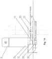
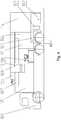
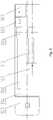
Fig. 1A is a schematic top view of a vehicle-mounted inspection system according to an embodiment of the present invention, in a scanning state.Fig. 1B is a schematic top view of the vehicle-mounted inspection system according to the embodiment of the present invention, in the scanning state, in which specific structures of components are shown.Fig. 2 is a schematic front view of a first imaging device of the vehicle-mounted inspection system according to an embodiment of the present invention, in the scanning state.Fig. 3 is a schematic front view of a second imaging device of the vehicle-mounted inspection system according to an embodiment of the present invention, in the scanning state.Fig. 4 is a schematic front view of the vehicle-mounted inspection system according to an embodiment of the present invention, in a transport state.Fig. 5 is a schematic top view of the vehicle-mounted inspection system according to the embodiment of the present invention, in the transport state.- A further description of the invention will be made in detail as below with reference to embodiments of the present invention taken in conjunction with the accompanying drawings.
- Referring to
Figs. 1A-5 , a vehicle-mounted inspection system according to an embodiment of the present invention comprises: a chassis 1011; arotation mechanism 105 disposed on the chassis 1011; a first ray emission device connected to therotation mechanism 105 and configured to emit a ray from one side of an object under inspection towards the other side of the object under inspection; a first detection device connected to therotation mechanism 105 and configured to receive the ray emitted by the first ray emission device; and a second ray emission device connected to therotation mechanism 105 and configured to emit a ray from above downwards. Therotation mechanism 105 is configured to rotate the first ray emission device, the first detection device and the second ray emission device substantially around an upright axis between a retracted position and an operating position. The chassis 1011 may comprise a chassis of avehicle 101, or a separate trailer dragged by a vehicle. Thevehicle 101 may comprise a chassis truck or a trailer truck. - Referring to
Figs. 1A-5 , the first ray emission device comprises afirst ray source 102 and afirst collimator 103; and the second ray emission device comprises a secondray source arm 112 and asecond ray source 109 and asecond collimator 110 disposed to the second ray source arm. The first detection device comprises a firsttraverse detector arm 106, a firstupright detector arm 107, and a plurality offirst detectors 108 disposed to the firsttransverse detector arm 106 and the firstupright detector arm 107. A first imaging device formed by the first ray emission device and the first detection device is configured to acquire a side-looking image of an object under inspection. - Referring to
Figs. 1A-5 , therotation mechanism 105 comprises: a rotary member; and a driving member configured to drive the rotary member to rotate around the upright axis, wherein the first ray emission device, the first detection device and the second ray emission device are connected to the rotary member. Therotation mechanism 105 may comprise an internal gear connected to the rotary member. The internal gear is driven to rotate through a pinion gear by an electric motor, thereby rotating the rotary member. - Referring to
Figs. 1A-5 , the vehicle-mounted inspection system further comprises: a firstelevating mechanism 104 connected to therotation mechanism 105 and configured to lift up and down the first detection device and a second elevatingmechanism 111 connected to therotation mechanism 105 and configured to lift up and down the second ray emission device. In the present embodiment, the first transverse detector arm is elevated by the firstelevating mechanism 104 and is rotated to the operating position by therotation mechanism 105 so as to enter an operational state. The secondray source arm 112 is elevated by the secondelevating mechanism 111 and is rotated to the operating position by therotation mechanism 105 so as to enter an operational state. In the operational state, the first transverse detector arm and the first upright detector arm are formed in a substantially inverted L shape. The object under inspection is inspected by passing it between the first ray emission device and the first upright detector arm. The elevating mechanism may comprise a hydraulic cylinder, a screw-and-nut mechanism or any other appropriate mechanism. - As shown in
Fig. 3 , the vehicle-mounted inspection system further comprises: a second detection device disposed on a ground surface and configured to receive the ray emitted by the second ray emission device. The second detection device comprises asecond detector 113 such as a plate type detector. A second imaging device formed by the second ray emission device and the second detection device is configured to acquire a look-down transmission image of an object under inspection. In the operational state, the object under inspection passes between the second ray emission device and the second detection device, i.e., below the second ray emission device while above the second detection device. - As shown in
Fig. 3 , the vehicle-mounted inspection system further comprises: a chamber disposed on a front side of therotation mechanism 105 on the chassis 1011, wherein in the retracted position, the first detection device and the second ray emission device are placed on a top of the chamber and are spaced from each other in a transverse direction of the chassis 1011. - In some embodiments, referring to
Figs. 1A-5 , the vehicle-mounted inspection system further comprises: anequipment chamber 114, anoperating chamber 115, and animage processing apparatus 116. - The
first ray source 102, thefirst collimator 103 and theequipment chamber 114 are located on one side of therotation mechanism 105 and are connected to therotation mechanism 105, while the first elevatingmechanism 104, the firsttransverse detector arm 106 and the firstupright detector arm 107 are mounted on the other side of therotation mechanism 105 and are connected to therotation mechanism 105. After the equipment reaches a work site, the first imaging device is unfolded in the following sequence. The first elevatingmechanism 104 is elevated to drive the firsttransverse detector arm 106 and the firstupright detector arm 107, which are in a folded state, to be elevated to an operating height, then, therotation mechanism 105 rotates clockwise to the operating position or any other particular angle, and finally, the firstupright detector arm 107 is unfolded downwards to the operating position to make an angle of about 90° with a ground surface. After the first imaging device is completely unfolded, thefirst collimator 103, the firsttransverse detector arm 106 and the firstupright detector arm 107 form a gantry structure. A ray emitted by thefirst ray source 102 is collimated by thefirst collimator 103 into a sectorial ray beam having a certain flare angle and emitted from a left side to a right side. After the sectorial ray beam incident upon a side surface of an object under inspection passes through the object, an attenuated ray signal is received by thefirst detectors 108 in the firsttransverse detector arm 106 and the firstupright detector arm 107, thereby acquiring information of side-looking transmission image of the object. The object is continuously moved along a length direction of the vehicle relative to the first imaging device, thereby acquiring information of the side-looking transmission image of the object in its full length. - The second elevating
mechanism 111 is mounted to therotation mechanism 105 and has an upper end connected to the secondray source arm 112. Thesecond ray source 109 and thesecond collimator 110 are mounted to the secondray source arm 112. The second imaging device is unfolded in the following sequence. The second elevatingmechanism 111 drives thesecond ray source 109 to be elevated to an operating height, and then therotation mechanism 105 rotates clockwise such that thesecond ray source 109 reaches an upper side over the object under inspection. In order to avoid a ray passing through the object from above downwards irradiates thevehicle 101 or theoperating chamber 115, a center of thesecond ray source 109 may be located at an upper left side of a scanning passage, rather than a center of the scanning passage. When a scanning is performed, a ray is emitted by thesecond ray source 109 and is collimated by thesecond collimator 110 into a sectorial ray beam having a certain flare angle and emitted from above downwards. After the sectorial ray beam substantially vertically incident upon a top of the object under inspection passes through the object, it is irradiated onto asecond detector 113 mounted on the ground surface temporarily, and an attenuated ray signal is received by thesecond detectors 113 to acquire information of look-down transmission image of the object. The object is continuously moved along a traveling direction of the vehicle relative to the second imaging device, thereby acquiring information of the transmission image of the object in its full length. - The
second detector 113 may comprise a plate type detector with a ramp so that a lorry can pass on thesecond detector 113 safely and conveniently. Thesecond detector 113 can sustain rolling of a heavy lorry, without being damaged. The second detector can also be mounted and retracted conveniently and quickly. - Accessory equipments of the
first ray source 102 and thesecond ray source 109 are mounted in theequipment chamber 114. Animage processing apparatus 116 is mounted in theoperating chamber 115, and theoperating chamber 116 is a workplace where an operator carries out daily operation and analyzes the image. The operating chamber may also be disposed in a space outside the vehicle-mounted inspection system and data transmission between the equipment in the space and the equipment in the vehicle is achieved by wire communication or wireless communication. The operatingchamber 115 has a chamber wall. The chamber wall has a layer of lead (or other shielding material) with a certain thickness for ray shielding purpose, to ensure that a level of ray dose in theoperating chamber 115 satisfies requirements of laws and regulations. - In a travel state, a transverse center of gravity of the entire vehicle-mounted inspection system is located in the vicinity of a central axis of the chassis and a longitudinal center of gravity of the entire vehicle-mounted inspection system is located at a rear axle. After the system is unfolded, both the detector arms of the first imaging device and the ray source of the second imaging device cantilever beyond the chassis. Therefore, a corresponding proportional balance weight is loaded in the equipment chamber to ensure that the transverse center of gravity is still located in the vicinity of the central axis of the chassis while the longitudinal center of gravity is still located at the rear axle. The vehicle-mounted inspection system satisfies dynamic and static stability requirements whether in the travel state where the imaging devices are retracted or in the operational state where the imaging devices are unfolded.
- A workflow of the inspection system according to the embodiment of the present invention will now be described. The
vehicle 101 reaches an appointed work site. The equipment is connected, powered on, and preheated. As described above, the first imaging device, the second imaging device and imaging devices of other viewing angles (if any) are unfolded in place and together to form a multiple viewing angle (the number of viewing angles n≥ 2) imaging region. After an object under inspection enters an inspection region, it first enters a first imaging region. In the first imaging region, the object slowly passes below the gantry formed by thefirst collimator 103, the firsttransverse detector arm 106 and the firstupright detector arm 107. A ray is emitted by thefirst ray source 102. After the ray incident upon a side surface of the object passes through the object, the ray is received by thefirst detectors 108, thereby acquiring a first image of the object. After that, the object reaches a second imaging region through the first imaging region. In the second imaging region, a ray is emitted by thesecond ray source 109. After the ray incident upon a top of the object passes through the object, the ray is received by thesecond detectors 113, thereby acquiring a second image of the object. After the object completely passes the multiple viewing angle imaging region, entire first, second and other information of image of the object is acquired by the detectors. A data processing and an image reconstruction of the information of image are performed by theimage processing apparatus 116. Thereby, multiple viewing angle transmission images of the object can be obtained by single scanning process. - In order to avoid scattering interferences between different ray sources and the detectors, emission of the ray beam and sampling are performed at intervals. During a whole operational period including a first imaging operation and a second imaging operation, when the first ray source emits a ray beam, a first trigger signal is simultaneously transmitted. The first detector performs sampling when receiving the first trigger signal and at the same time the second ray source is interlocked such that the second ray source does not emit a ray beam and thereby the second detector is prohibited from sampling, which ensures that the first detector receives only the attenuated ray emitted by the first ray source and passing through the object under inspection. Likewise, the second imaging device is operated in a similar manner to that of the first imaging device. The two imaging devices perform ray beam emissions and samplings at intervals. In other words, they cooperates and do not interfere with each other. Provided that the system includes more than two imaging devices, the system is operated in the same operational principle as the abovementioned system having two imaging devices. Two or more imaging devices can operate independently of each other or operate simultaneously. For example, the first ray source and the second ray source alternately emit ray beams.
- The image data acquired from multiple viewing angles are processed independently of each other, to obtain information of multiple viewing angle image. The information of image acquired from the first viewing angle, the second viewing angle, and the like are displayed on two or more displays, respectively. Profiles and transmission images of the closed object viewed from different viewing angles can be seen clearly and conveniently, for further judging property of the object.
- The plurality of imaging devices may simultaneously perform the scannings and imagings on an object from a plurality of viewing angles, or, one or more of the plurality of imaging devices is selectively used to perform the imagings on an object from one or more viewing angles.
- The system according to the embodiments of the present invention has two states. One of the two states is a transport state and the other is a scanning state. When the system needs to be transported, all of the ray source arms and the elevating devices are retracted and the detector arms are folded so that the system is switched to the transport state. In this case, overall dimensions of the system completely satisfy road transport requirements. When the system reaches a detection site, all of the arms and the elevating devices are unfolded so that the system is switched to the scanning state. During a scanning, the object passes in the gantry, and the plurality of imaging devices may operate simultaneously, or one or more of the plurality of imaging devices may operate. In order to avoid the influence of unnecessary scattering on image quality, when the plurality of imaging devices operate simultaneously, the plurality of ray sources emit rays from a side of an object, from above, or from another viewing angle at intervals, while the plurality of detectors receive ray signals at the other side of the object, at a bottom, or at another position or from another direction according to ray beam emission signals to the ray sources, respectively, and image reconstruction is performed. Ray transmission images viewed from a plurality of directions or angles are obtained. Thereby, a single scanning process is required in order to obtain whole multiple viewing angle transmission images.
- In addition, the system according to the embodiments of the present invention may further comprise a third ray emission device and a third detection device. The third ray emission device may be located on an opposite side to the first ray emission device (i.e., an inner side of the first upright detector arm 107), on the same side as the first ray emission device in an up-down direction or a left-right direction, or on a left, right, front, or rear side of the second ray emission device.
- The vehicle-mounted inspection system according to the embodiments of the present invention is, for example, simple in structure, low in cost, and high in inspection efficiency.
- The vehicle-mounted inspection system according to the embodiments of the present invention comprises a plurality of ray emission devices and a plurality of detection devices, which acquires transmission images of an object under inspection viewed from a plurality of angles.
- In the embodiments, the plurality of imaging devices is mounted to one vehicle. Therefore, transmission images of an object viewed from a plurality of angles are acquired during a single scanning process, and incorrect judgments due to superposition of transmission images of the object are reduced. Transmission images of the object are reflected conveniently, quickly, and genuinely. Inspection quality and inspection efficiency are improved. The system is simple in structure, economic, practical, high in integrity, mobile and flexible.
Claims (8)
- A vehicle-mounted inspection system for scanning an object under inspection in a scanning state and for traveling in a transport state,
the system comprising:a chassis (1011);a rotation mechanism (105) disposed on the chassis (1011);a first x-ray emission device connected to the rotation mechanism (105) and configured to emit an x-ray from one side of an object under inspection towards the other side of the object under inspection;a first detection device connected to the rotation mechanism (105) and configured to receive the x-ray emitted by the first x-ray emission device;wherein the system further comprisesa second x-ray emission device connected to the rotation mechanism (105) and configured to emit an x-ray from above downwards; andan elevating mechanism (111) connected to the rotation mechanism (105) and configured to lift up and down the second x-ray emission device, wherein:the rotation mechanism (105) is configured to rotate the first x-ray emission device, the first detection device and the second x-ray emission device substantially around an upright axis between a retracted position in the transport state and an operating position in the scanning state,the second x-ray emission device comprises a second x-ray source arm (112) and a second x-ray source (109) disposed to the second x-ray source arm (112), andthe elevating mechanism (111) is adapted to elevate the second x-ray source arm (112) and the rotation mechanism (105) is adapted to rotate the second x-ray source arm (112) such that the second x-ray source arm (112) enters the scanning state. - The vehicle-mounted inspection system of claim 1, further comprising:
a further elevating mechanism (104) connected to the rotation mechanism (105) and configured to lift up and down the first detection device. - The vehicle-mounted inspection system of claim 1, wherein:the rotation mechanism (105) comprises: a rotary member, and a driving member configured to drive the rotary member to rotate around the upright axis, andthe first x-ray emission device, the first detection device and the second x-ray emission device are connected to the rotary member.
- The vehicle-mounted inspection system of claim 2, wherein:
the first detection device comprises a transverse detector arm (106) and an upright detector arm (107), and a plurality of detectors disposed to the transverse detector arm (106) and the upright detector arm (107), and in the scanning state, the transverse detector arm (106) and the upright detector arm (107) are formed in a substantially inverted L shape. - The vehicle-mounted inspection system of claim 4, wherein:
the transverse detector arm (106) is elevated by the further elevating mechanism (104) and is rotated to the operating position by the rotation mechanism (105) so as to enter the scanning state. - The vehicle-mounted inspection system of claim 1, further comprising:
a second detection device disposed on a ground surface and configured to receive the x-ray emitted by the second x-ray emission device. - The vehicle-mounted inspection system of claim 1, wherein:
the second detection device comprises a plate type detector (113). - The vehicle-mounted inspection system of claim 1, further comprising:a chamber disposed on a front side of the rotation mechanism (105) on the chassis (1011),wherein in the retracted position, the first detection device and the second x-ray emission device are placed on a top of the chamber and are spaced from each other in a transverse direction of the chassis (1011).
Priority Applications (1)
| Application Number | Priority Date | Filing Date | Title |
|---|---|---|---|
| PL15183367TPL2993495T3 (en) | 2014-09-02 | 2015-09-01 | Vehicle-mounted inspection system |
Applications Claiming Priority (1)
| Application Number | Priority Date | Filing Date | Title |
|---|---|---|---|
| CN201410443085.0ACN105445294B (en) | 2014-09-02 | 2014-09-02 | Vehicle-mounted inspection system |
Publications (2)
| Publication Number | Publication Date |
|---|---|
| EP2993495A1 EP2993495A1 (en) | 2016-03-09 |
| EP2993495B1true EP2993495B1 (en) | 2019-06-19 |
Family
ID=54150235
Family Applications (1)
| Application Number | Title | Priority Date | Filing Date |
|---|---|---|---|
| EP15183367.0AActiveEP2993495B1 (en) | 2014-09-02 | 2015-09-01 | Vehicle-mounted inspection system |
Country Status (7)
| Country | Link |
|---|---|
| US (1) | US9897716B2 (en) |
| EP (1) | EP2993495B1 (en) |
| CN (1) | CN105445294B (en) |
| CA (1) | CA2902952C (en) |
| MX (1) | MX360055B (en) |
| PL (1) | PL2993495T3 (en) |
| WO (1) | WO2016034101A2 (en) |
Families Citing this family (27)
| Publication number | Priority date | Publication date | Assignee | Title |
|---|---|---|---|---|
| CN105438255B (en)* | 2015-12-29 | 2018-12-21 | 同方威视技术股份有限公司 | A kind of steering boost system and vehicle-mounted inspection equipment |
| CN106230088B (en)* | 2016-07-22 | 2019-02-15 | 清华大学 | Vehicle-mounted inspection system, power supply system, control method, and power supply controller thereof |
| EP3505919B1 (en) | 2016-08-25 | 2024-07-17 | Beijing Hualixing Technology Development Co., Ltd. | Imaging device for use in vehicle security check and method therefor |
| CN106290422B (en)* | 2016-08-25 | 2020-09-08 | 北京华力兴科技发展有限责任公司 | Imaging device and method for vehicle safety inspection |
| CN106290420B (en)* | 2016-08-31 | 2019-11-12 | 同方威视技术股份有限公司 | Movable item inspection system and inspection method |
| CN106420032B (en) | 2016-08-31 | 2019-07-26 | 苏州西脉新诚生物科技有限公司 | A kind of multiway fastening bone screws |
| CN106772650A (en)* | 2016-12-26 | 2017-05-31 | 同方威视技术股份有限公司 | Portable explosive transmission imaging device |
| CN109154791B (en)* | 2017-02-24 | 2021-08-20 | 京瓷办公信息系统株式会社 | Reciprocating mechanism of moving body, cleaning mechanism, optical scanning device, and image forming apparatus |
| KR102257665B1 (en)* | 2017-08-18 | 2021-05-31 | 후지 덴키 가부시키가이샤 | X-ray inspection system and X-ray receiving device |
| CN107991323A (en)* | 2017-11-21 | 2018-05-04 | 同方威视技术股份有限公司 | Vehicle mounted type radiation checking system |
| CN107765320B (en)* | 2017-11-24 | 2025-01-10 | 同方威视技术股份有限公司 | Check the system |
| CN108227027B (en)* | 2017-12-29 | 2020-12-01 | 同方威视技术股份有限公司 | Vehicle Backscatter Inspection System |
| CN109581528B (en)* | 2018-11-21 | 2021-02-09 | 南京森林警察学院 | An efficient drug detection device |
| CN109828310B (en)* | 2018-12-28 | 2024-05-03 | 同方威视技术股份有限公司 | Security inspection equipment and security inspection method |
| CN109521481B (en)* | 2019-01-04 | 2024-12-20 | 同方威视技术股份有限公司 | Inspection device |
| CN109521483B (en)* | 2019-01-04 | 2024-05-14 | 同方威视科技(北京)有限公司 | Check the equipment |
| CN109799249B (en)* | 2019-02-27 | 2024-02-23 | 中国工程物理研究院机械制造工艺研究所 | Vehicle-mounted CT nondestructive testing system |
| CN110261927A (en)* | 2019-07-12 | 2019-09-20 | 北京华力兴科技发展有限责任公司 | Ray detection system |
| CN113740924B (en)* | 2020-05-29 | 2023-05-23 | 同方威视技术股份有限公司 | Accelerator and vehicle-mounted radiation imaging equipment |
| CN113022608A (en)* | 2021-04-01 | 2021-06-25 | 中车四方车辆有限公司 | Vehicle-mounted DR inspection room |
| CN112946770B (en)* | 2021-05-17 | 2021-08-10 | 同方威视技术股份有限公司 | Scanning and checking equipment and scanning and checking systems |
| CN115097536B (en)* | 2021-07-07 | 2024-05-14 | 同方威视技术股份有限公司 | Inspection system and method |
| CN115616008B (en)* | 2021-07-13 | 2023-12-15 | 同方威视技术股份有限公司 | Booms, mobile radiation detection equipment, acceptance systems and security inspection methods |
| CN114137622A (en)* | 2021-12-30 | 2022-03-04 | 同方威视科技(北京)有限公司 | Mobile radiation inspection apparatus and mobile radiation inspection system |
| CN114167509B (en)* | 2021-12-30 | 2025-07-15 | 同方威视科技(北京)有限公司 | Mobile inspection equipment and mobile inspection method |
| CN117420162B (en)* | 2023-08-31 | 2024-06-04 | 华能核能技术研究院有限公司 | Mobile device and graphite dust accumulation amount online measurement system |
| CN117871555A (en)* | 2023-12-26 | 2024-04-12 | 同方威视技术股份有限公司 | Mobile inspection device and mobile inspection system |
Family Cites Families (13)
| Publication number | Priority date | Publication date | Assignee | Title |
|---|---|---|---|---|
| US7963695B2 (en)* | 2002-07-23 | 2011-06-21 | Rapiscan Systems, Inc. | Rotatable boom cargo scanning system |
| JP2008298509A (en) | 2007-05-30 | 2008-12-11 | Ihi Corp | Mobile radiation inspection device |
| CN101329285A (en) | 2007-06-20 | 2008-12-24 | 沈阳华德汽车贸易有限公司 | Vehicle mounted checking system of cobalt-60 container |
| CN101344597A (en)* | 2007-07-11 | 2009-01-14 | 宋世鹏 | Vehicle-mounted article inspection device |
| CN101936925A (en)* | 2009-06-30 | 2011-01-05 | 同方威视技术股份有限公司 | Vehicle-mounted container detection system of semi-trailer |
| MY154268A (en)* | 2009-07-29 | 2015-05-29 | American Science & Eng Inc | Top-down x-ray inspection trailer |
| US8824632B2 (en)* | 2009-07-29 | 2014-09-02 | American Science And Engineering, Inc. | Backscatter X-ray inspection van with top-down imaging |
| US20110186739A1 (en)* | 2010-02-04 | 2011-08-04 | L-3 Communications Security and Detection Systems Inc. | Mobile tomographic cargo inspection system |
| JP5475575B2 (en) | 2010-07-06 | 2014-04-16 | 株式会社Ihi検査計測 | Vehicle transport device for X-ray inspection |
| CN102556185A (en)* | 2010-12-31 | 2012-07-11 | 同方威视技术股份有限公司 | Semi-trailer self-travelling system, vehicle-mounted radiation detection system and use method thereof |
| WO2013016032A2 (en)* | 2011-07-26 | 2013-01-31 | American Science And Engineering, Inc. | Stowable arcuate detector array |
| JP2013064619A (en) | 2011-09-16 | 2013-04-11 | Ihi Inspection & Instrumentation Co Ltd | Cargo multi-angle inspection device and method |
| CN204086172U (en)* | 2014-09-02 | 2015-01-07 | 清华大学 | Vehicular check system |
- 2014
- 2014-09-02CNCN201410443085.0Apatent/CN105445294B/enactiveActive
- 2015
- 2015-09-01PLPL15183367Tpatent/PL2993495T3/enunknown
- 2015-09-01WOPCT/CN2015/088732patent/WO2016034101A2/enactiveApplication Filing
- 2015-09-01EPEP15183367.0Apatent/EP2993495B1/enactiveActive
- 2015-09-01CACA2902952Apatent/CA2902952C/enactiveActive
- 2015-09-01MXMX2016009995Apatent/MX360055B/enactiveIP Right Grant
- 2015-09-01USUS14/841,991patent/US9897716B2/enactiveActive
Non-Patent Citations (1)
| Title |
|---|
| None* |
Also Published As
| Publication number | Publication date |
|---|---|
| CN105445294A (en) | 2016-03-30 |
| MX360055B (en) | 2018-10-19 |
| CN105445294B (en) | 2019-02-22 |
| WO2016034101A3 (en) | 2016-04-28 |
| WO2016034101A2 (en) | 2016-03-10 |
| CA2902952C (en) | 2017-10-17 |
| PL2993495T3 (en) | 2019-11-29 |
| US9897716B2 (en) | 2018-02-20 |
| CA2902952A1 (en) | 2016-03-02 |
| MX2016009995A (en) | 2017-04-27 |
| HK1222906A1 (en) | 2017-07-14 |
| US20160061989A1 (en) | 2016-03-03 |
| EP2993495A1 (en) | 2016-03-09 |
Similar Documents
| Publication | Publication Date | Title |
|---|---|---|
| EP2993495B1 (en) | Vehicle-mounted inspection system | |
| US11550077B2 (en) | Portable vehicle inspection portal with accompanying workstation | |
| JP4664907B2 (en) | On-vehicle inspection system and method | |
| RU2595291C2 (en) | Methods of performing back-scattering survey complex targets in confined spaces | |
| JP6401603B2 (en) | X-ray fluoroscopic imaging system | |
| US9658173B2 (en) | Portable x-ray backscattering imaging system including a radioactive source | |
| US8971487B2 (en) | Stowable arcuate detector array | |
| JP6572326B2 (en) | Security inspection device and radiation detection method | |
| CN204086172U (en) | Vehicular check system | |
| CN108549111B (en) | Mobile in-vehicle panoramic X-ray back scattering scanning security inspection device | |
| CN102483383A (en) | From top to bottom X-ray inspection trailer | |
| US9989668B2 (en) | Inspection system for container | |
| CN108508049A (en) | A kind of mobile sedan chassis safety check apparatus based on X-ray back scattering | |
| US8687764B2 (en) | Robotic sensor | |
| Swift et al. | Medium energy x-ray examination of commercial trucks | |
| CN112946769A (en) | Security check equipment, security check method and warehousing system | |
| HK1222906B (en) | Vehicle-borne inspection system | |
| CN117191833A (en) | Object scanning device |
Legal Events
| Date | Code | Title | Description |
|---|---|---|---|
| PUAI | Public reference made under article 153(3) epc to a published international application that has entered the european phase | Free format text:ORIGINAL CODE: 0009012 | |
| 17P | Request for examination filed | Effective date:20150901 | |
| AK | Designated contracting states | Kind code of ref document:A1 Designated state(s):AL AT BE BG CH CY CZ DE DK EE ES FI FR GB GR HR HU IE IS IT LI LT LU LV MC MK MT NL NO PL PT RO RS SE SI SK SM TR | |
| AX | Request for extension of the european patent | Extension state:BA ME | |
| STAA | Information on the status of an ep patent application or granted ep patent | Free format text:STATUS: EXAMINATION IS IN PROGRESS | |
| 17Q | First examination report despatched | Effective date:20170627 | |
| GRAP | Despatch of communication of intention to grant a patent | Free format text:ORIGINAL CODE: EPIDOSNIGR1 | |
| STAA | Information on the status of an ep patent application or granted ep patent | Free format text:STATUS: GRANT OF PATENT IS INTENDED | |
| INTG | Intention to grant announced | Effective date:20190111 | |
| GRAS | Grant fee paid | Free format text:ORIGINAL CODE: EPIDOSNIGR3 | |
| GRAA | (expected) grant | Free format text:ORIGINAL CODE: 0009210 | |
| STAA | Information on the status of an ep patent application or granted ep patent | Free format text:STATUS: THE PATENT HAS BEEN GRANTED | |
| AK | Designated contracting states | Kind code of ref document:B1 Designated state(s):AL AT BE BG CH CY CZ DE DK EE ES FI FR GB GR HR HU IE IS IT LI LT LU LV MC MK MT NL NO PL PT RO RS SE SI SK SM TR | |
| REG | Reference to a national code | Ref country code:GB Ref legal event code:FG4D | |
| REG | Reference to a national code | Ref country code:CH Ref legal event code:EP | |
| REG | Reference to a national code | Ref country code:IE Ref legal event code:FG4D | |
| REG | Reference to a national code | Ref country code:DE Ref legal event code:R096 Ref document number:602015032136 Country of ref document:DE | |
| REG | Reference to a national code | Ref country code:AT Ref legal event code:REF Ref document number:1146227 Country of ref document:AT Kind code of ref document:T Effective date:20190715 | |
| REG | Reference to a national code | Ref country code:NL Ref legal event code:FP | |
| PG25 | Lapsed in a contracting state [announced via postgrant information from national office to epo] | Ref country code:FI Free format text:LAPSE BECAUSE OF FAILURE TO SUBMIT A TRANSLATION OF THE DESCRIPTION OR TO PAY THE FEE WITHIN THE PRESCRIBED TIME-LIMIT Effective date:20190619 Ref country code:NO Free format text:LAPSE BECAUSE OF FAILURE TO SUBMIT A TRANSLATION OF THE DESCRIPTION OR TO PAY THE FEE WITHIN THE PRESCRIBED TIME-LIMIT Effective date:20190919 Ref country code:HR Free format text:LAPSE BECAUSE OF FAILURE TO SUBMIT A TRANSLATION OF THE DESCRIPTION OR TO PAY THE FEE WITHIN THE PRESCRIBED TIME-LIMIT Effective date:20190619 Ref country code:AL Free format text:LAPSE BECAUSE OF FAILURE TO SUBMIT A TRANSLATION OF THE DESCRIPTION OR TO PAY THE FEE WITHIN THE PRESCRIBED TIME-LIMIT Effective date:20190619 Ref country code:LT Free format text:LAPSE BECAUSE OF FAILURE TO SUBMIT A TRANSLATION OF THE DESCRIPTION OR TO PAY THE FEE WITHIN THE PRESCRIBED TIME-LIMIT Effective date:20190619 Ref country code:SE Free format text:LAPSE BECAUSE OF FAILURE TO SUBMIT A TRANSLATION OF THE DESCRIPTION OR TO PAY THE FEE WITHIN THE PRESCRIBED TIME-LIMIT Effective date:20190619 | |
| REG | Reference to a national code | Ref country code:LT Ref legal event code:MG4D | |
| PG25 | Lapsed in a contracting state [announced via postgrant information from national office to epo] | Ref country code:GR Free format text:LAPSE BECAUSE OF FAILURE TO SUBMIT A TRANSLATION OF THE DESCRIPTION OR TO PAY THE FEE WITHIN THE PRESCRIBED TIME-LIMIT Effective date:20190920 Ref country code:RS Free format text:LAPSE BECAUSE OF FAILURE TO SUBMIT A TRANSLATION OF THE DESCRIPTION OR TO PAY THE FEE WITHIN THE PRESCRIBED TIME-LIMIT Effective date:20190619 Ref country code:BG Free format text:LAPSE BECAUSE OF FAILURE TO SUBMIT A TRANSLATION OF THE DESCRIPTION OR TO PAY THE FEE WITHIN THE PRESCRIBED TIME-LIMIT Effective date:20190919 Ref country code:LV Free format text:LAPSE BECAUSE OF FAILURE TO SUBMIT A TRANSLATION OF THE DESCRIPTION OR TO PAY THE FEE WITHIN THE PRESCRIBED TIME-LIMIT Effective date:20190619 | |
| REG | Reference to a national code | Ref country code:AT Ref legal event code:MK05 Ref document number:1146227 Country of ref document:AT Kind code of ref document:T Effective date:20190619 | |
| PG25 | Lapsed in a contracting state [announced via postgrant information from national office to epo] | Ref country code:CZ Free format text:LAPSE BECAUSE OF FAILURE TO SUBMIT A TRANSLATION OF THE DESCRIPTION OR TO PAY THE FEE WITHIN THE PRESCRIBED TIME-LIMIT Effective date:20190619 Ref country code:RO Free format text:LAPSE BECAUSE OF FAILURE TO SUBMIT A TRANSLATION OF THE DESCRIPTION OR TO PAY THE FEE WITHIN THE PRESCRIBED TIME-LIMIT Effective date:20190619 Ref country code:SK Free format text:LAPSE BECAUSE OF FAILURE TO SUBMIT A TRANSLATION OF THE DESCRIPTION OR TO PAY THE FEE WITHIN THE PRESCRIBED TIME-LIMIT Effective date:20190619 Ref country code:AT Free format text:LAPSE BECAUSE OF FAILURE TO SUBMIT A TRANSLATION OF THE DESCRIPTION OR TO PAY THE FEE WITHIN THE PRESCRIBED TIME-LIMIT Effective date:20190619 Ref country code:PT Free format text:LAPSE BECAUSE OF FAILURE TO SUBMIT A TRANSLATION OF THE DESCRIPTION OR TO PAY THE FEE WITHIN THE PRESCRIBED TIME-LIMIT Effective date:20191021 Ref country code:EE Free format text:LAPSE BECAUSE OF FAILURE TO SUBMIT A TRANSLATION OF THE DESCRIPTION OR TO PAY THE FEE WITHIN THE PRESCRIBED TIME-LIMIT Effective date:20190619 | |
| PG25 | Lapsed in a contracting state [announced via postgrant information from national office to epo] | Ref country code:SM Free format text:LAPSE BECAUSE OF FAILURE TO SUBMIT A TRANSLATION OF THE DESCRIPTION OR TO PAY THE FEE WITHIN THE PRESCRIBED TIME-LIMIT Effective date:20190619 Ref country code:IT Free format text:LAPSE BECAUSE OF FAILURE TO SUBMIT A TRANSLATION OF THE DESCRIPTION OR TO PAY THE FEE WITHIN THE PRESCRIBED TIME-LIMIT Effective date:20190619 Ref country code:ES Free format text:LAPSE BECAUSE OF FAILURE TO SUBMIT A TRANSLATION OF THE DESCRIPTION OR TO PAY THE FEE WITHIN THE PRESCRIBED TIME-LIMIT Effective date:20190619 Ref country code:IS Free format text:LAPSE BECAUSE OF FAILURE TO SUBMIT A TRANSLATION OF THE DESCRIPTION OR TO PAY THE FEE WITHIN THE PRESCRIBED TIME-LIMIT Effective date:20191019 | |
| PG25 | Lapsed in a contracting state [announced via postgrant information from national office to epo] | Ref country code:TR Free format text:LAPSE BECAUSE OF FAILURE TO SUBMIT A TRANSLATION OF THE DESCRIPTION OR TO PAY THE FEE WITHIN THE PRESCRIBED TIME-LIMIT Effective date:20190619 | |
| PG25 | Lapsed in a contracting state [announced via postgrant information from national office to epo] | Ref country code:DK Free format text:LAPSE BECAUSE OF FAILURE TO SUBMIT A TRANSLATION OF THE DESCRIPTION OR TO PAY THE FEE WITHIN THE PRESCRIBED TIME-LIMIT Effective date:20190619 | |
| PG25 | Lapsed in a contracting state [announced via postgrant information from national office to epo] | Ref country code:MC Free format text:LAPSE BECAUSE OF FAILURE TO SUBMIT A TRANSLATION OF THE DESCRIPTION OR TO PAY THE FEE WITHIN THE PRESCRIBED TIME-LIMIT Effective date:20190619 Ref country code:IS Free format text:LAPSE BECAUSE OF FAILURE TO SUBMIT A TRANSLATION OF THE DESCRIPTION OR TO PAY THE FEE WITHIN THE PRESCRIBED TIME-LIMIT Effective date:20200224 | |
| REG | Reference to a national code | Ref country code:CH Ref legal event code:PL | |
| REG | Reference to a national code | Ref country code:DE Ref legal event code:R097 Ref document number:602015032136 Country of ref document:DE | |
| PLBE | No opposition filed within time limit | Free format text:ORIGINAL CODE: 0009261 | |
| STAA | Information on the status of an ep patent application or granted ep patent | Free format text:STATUS: NO OPPOSITION FILED WITHIN TIME LIMIT | |
| PG2D | Information on lapse in contracting state deleted | Ref country code:IS | |
| PG25 | Lapsed in a contracting state [announced via postgrant information from national office to epo] | Ref country code:CH Free format text:LAPSE BECAUSE OF NON-PAYMENT OF DUE FEES Effective date:20190930 Ref country code:LI Free format text:LAPSE BECAUSE OF NON-PAYMENT OF DUE FEES Effective date:20190930 Ref country code:LU Free format text:LAPSE BECAUSE OF NON-PAYMENT OF DUE FEES Effective date:20190901 Ref country code:IE Free format text:LAPSE BECAUSE OF NON-PAYMENT OF DUE FEES Effective date:20190901 | |
| REG | Reference to a national code | Ref country code:BE Ref legal event code:MM Effective date:20190930 | |
| 26N | No opposition filed | Effective date:20200603 | |
| PG25 | Lapsed in a contracting state [announced via postgrant information from national office to epo] | Ref country code:SI Free format text:LAPSE BECAUSE OF FAILURE TO SUBMIT A TRANSLATION OF THE DESCRIPTION OR TO PAY THE FEE WITHIN THE PRESCRIBED TIME-LIMIT Effective date:20190619 Ref country code:BE Free format text:LAPSE BECAUSE OF NON-PAYMENT OF DUE FEES Effective date:20190930 | |
| PG25 | Lapsed in a contracting state [announced via postgrant information from national office to epo] | Ref country code:CY Free format text:LAPSE BECAUSE OF FAILURE TO SUBMIT A TRANSLATION OF THE DESCRIPTION OR TO PAY THE FEE WITHIN THE PRESCRIBED TIME-LIMIT Effective date:20190619 | |
| PG25 | Lapsed in a contracting state [announced via postgrant information from national office to epo] | Ref country code:HU Free format text:LAPSE BECAUSE OF FAILURE TO SUBMIT A TRANSLATION OF THE DESCRIPTION OR TO PAY THE FEE WITHIN THE PRESCRIBED TIME-LIMIT; INVALID AB INITIO Effective date:20150901 Ref country code:MT Free format text:LAPSE BECAUSE OF FAILURE TO SUBMIT A TRANSLATION OF THE DESCRIPTION OR TO PAY THE FEE WITHIN THE PRESCRIBED TIME-LIMIT Effective date:20190619 | |
| PG25 | Lapsed in a contracting state [announced via postgrant information from national office to epo] | Ref country code:MK Free format text:LAPSE BECAUSE OF FAILURE TO SUBMIT A TRANSLATION OF THE DESCRIPTION OR TO PAY THE FEE WITHIN THE PRESCRIBED TIME-LIMIT Effective date:20190619 | |
| P01 | Opt-out of the competence of the unified patent court (upc) registered | Effective date:20230528 | |
| PGFP | Annual fee paid to national office [announced via postgrant information from national office to epo] | Ref country code:DE Payment date:20240919 Year of fee payment:10 | |
| PGFP | Annual fee paid to national office [announced via postgrant information from national office to epo] | Ref country code:GB Payment date:20240709 Year of fee payment:10 | |
| PGFP | Annual fee paid to national office [announced via postgrant information from national office to epo] | Ref country code:FR Payment date:20240701 Year of fee payment:10 | |
| PGFP | Annual fee paid to national office [announced via postgrant information from national office to epo] | Ref country code:NL Payment date:20240920 Year of fee payment:10 | |
| PGFP | Annual fee paid to national office [announced via postgrant information from national office to epo] | Ref country code:PL Payment date:20240823 Year of fee payment:10 |