EP2992395B1 - Operating light emitting diodes at low temperature - Google Patents
Operating light emitting diodes at low temperatureDownload PDFInfo
- Publication number
- EP2992395B1 EP2992395B1EP14791232.3AEP14791232AEP2992395B1EP 2992395 B1EP2992395 B1EP 2992395B1EP 14791232 AEP14791232 AEP 14791232AEP 2992395 B1EP2992395 B1EP 2992395B1
- Authority
- EP
- European Patent Office
- Prior art keywords
- light emitting
- voltage
- temperature
- emitting diodes
- leds
- Prior art date
- Legal status (The legal status is an assumption and is not a legal conclusion. Google has not performed a legal analysis and makes no representation as to the accuracy of the status listed.)
- Active
Links
- 230000004044responseEffects0.000claimsdescription12
- 238000000034methodMethods0.000claimsdescription11
- 230000007423decreaseEffects0.000claimsdescription8
- 238000005259measurementMethods0.000description12
- 238000010586diagramMethods0.000description7
- 230000001105regulatory effectEffects0.000description5
- 238000012544monitoring processMethods0.000description4
- 238000009529body temperature measurementMethods0.000description3
- 238000006243chemical reactionMethods0.000description3
- 230000000694effectsEffects0.000description3
- 238000012360testing methodMethods0.000description3
- 230000003247decreasing effectEffects0.000description2
- 230000001419dependent effectEffects0.000description2
- 230000005669field effectEffects0.000description2
- 230000000737periodic effectEffects0.000description2
- DGAQECJNVWCQMB-PUAWFVPOSA-MIlexoside XXIXChemical compoundC[C@@H]1CC[C@@]2(CC[C@@]3(C(=CC[C@H]4[C@]3(CC[C@@H]5[C@@]4(CC[C@@H](C5(C)C)OS(=O)(=O)[O-])C)C)[C@@H]2[C@]1(C)O)C)C(=O)O[C@H]6[C@@H]([C@H]([C@@H]([C@H](O6)CO)O)O)O.[Na+]DGAQECJNVWCQMB-PUAWFVPOSA-M0.000description1
- 239000003795chemical substances by applicationSubstances0.000description1
- 230000001276controlling effectEffects0.000description1
- 238000013461designMethods0.000description1
- 238000005265energy consumptionMethods0.000description1
- 238000003306harvestingMethods0.000description1
- 230000003116impacting effectEffects0.000description1
- 238000005057refrigerationMethods0.000description1
- 229910052708sodiumInorganic materials0.000description1
- 239000011734sodiumSubstances0.000description1
Images


Classifications
- H—ELECTRICITY
- H05—ELECTRIC TECHNIQUES NOT OTHERWISE PROVIDED FOR
- H05B—ELECTRIC HEATING; ELECTRIC LIGHT SOURCES NOT OTHERWISE PROVIDED FOR; CIRCUIT ARRANGEMENTS FOR ELECTRIC LIGHT SOURCES, IN GENERAL
- H05B45/00—Circuit arrangements for operating light-emitting diodes [LED]
- H05B45/30—Driver circuits
- H05B45/395—Linear regulators
- H—ELECTRICITY
- H05—ELECTRIC TECHNIQUES NOT OTHERWISE PROVIDED FOR
- H05B—ELECTRIC HEATING; ELECTRIC LIGHT SOURCES NOT OTHERWISE PROVIDED FOR; CIRCUIT ARRANGEMENTS FOR ELECTRIC LIGHT SOURCES, IN GENERAL
- H05B45/00—Circuit arrangements for operating light-emitting diodes [LED]
- H05B45/10—Controlling the intensity of the light
- H—ELECTRICITY
- H05—ELECTRIC TECHNIQUES NOT OTHERWISE PROVIDED FOR
- H05B—ELECTRIC HEATING; ELECTRIC LIGHT SOURCES NOT OTHERWISE PROVIDED FOR; CIRCUIT ARRANGEMENTS FOR ELECTRIC LIGHT SOURCES, IN GENERAL
- H05B45/00—Circuit arrangements for operating light-emitting diodes [LED]
- H05B45/40—Details of LED load circuits
- H05B45/44—Details of LED load circuits with an active control inside an LED matrix
- H05B45/46—Details of LED load circuits with an active control inside an LED matrix having LEDs disposed in parallel lines
- H—ELECTRICITY
- H05—ELECTRIC TECHNIQUES NOT OTHERWISE PROVIDED FOR
- H05B—ELECTRIC HEATING; ELECTRIC LIGHT SOURCES NOT OTHERWISE PROVIDED FOR; CIRCUIT ARRANGEMENTS FOR ELECTRIC LIGHT SOURCES, IN GENERAL
- H05B45/00—Circuit arrangements for operating light-emitting diodes [LED]
- H05B45/40—Details of LED load circuits
- H05B45/44—Details of LED load circuits with an active control inside an LED matrix
- H05B45/48—Details of LED load circuits with an active control inside an LED matrix having LEDs organised in strings and incorporating parallel shunting devices
- H—ELECTRICITY
- H05—ELECTRIC TECHNIQUES NOT OTHERWISE PROVIDED FOR
- H05B—ELECTRIC HEATING; ELECTRIC LIGHT SOURCES NOT OTHERWISE PROVIDED FOR; CIRCUIT ARRANGEMENTS FOR ELECTRIC LIGHT SOURCES, IN GENERAL
- H05B45/00—Circuit arrangements for operating light-emitting diodes [LED]
- H05B45/50—Circuit arrangements for operating light-emitting diodes [LED] responsive to malfunctions or undesirable behaviour of LEDs; responsive to LED life; Protective circuits
- H05B45/54—Circuit arrangements for operating light-emitting diodes [LED] responsive to malfunctions or undesirable behaviour of LEDs; responsive to LED life; Protective circuits in a series array of LEDs
- H—ELECTRICITY
- H05—ELECTRIC TECHNIQUES NOT OTHERWISE PROVIDED FOR
- H05B—ELECTRIC HEATING; ELECTRIC LIGHT SOURCES NOT OTHERWISE PROVIDED FOR; CIRCUIT ARRANGEMENTS FOR ELECTRIC LIGHT SOURCES, IN GENERAL
- H05B45/00—Circuit arrangements for operating light-emitting diodes [LED]
- H05B45/50—Circuit arrangements for operating light-emitting diodes [LED] responsive to malfunctions or undesirable behaviour of LEDs; responsive to LED life; Protective circuits
- H05B45/56—Circuit arrangements for operating light-emitting diodes [LED] responsive to malfunctions or undesirable behaviour of LEDs; responsive to LED life; Protective circuits involving measures to prevent abnormal temperature of the LEDs
- H—ELECTRICITY
- H05—ELECTRIC TECHNIQUES NOT OTHERWISE PROVIDED FOR
- H05B—ELECTRIC HEATING; ELECTRIC LIGHT SOURCES NOT OTHERWISE PROVIDED FOR; CIRCUIT ARRANGEMENTS FOR ELECTRIC LIGHT SOURCES, IN GENERAL
- H05B45/00—Circuit arrangements for operating light-emitting diodes [LED]
- H05B45/10—Controlling the intensity of the light
- H05B45/12—Controlling the intensity of the light using optical feedback
- H—ELECTRICITY
- H05—ELECTRIC TECHNIQUES NOT OTHERWISE PROVIDED FOR
- H05B—ELECTRIC HEATING; ELECTRIC LIGHT SOURCES NOT OTHERWISE PROVIDED FOR; CIRCUIT ARRANGEMENTS FOR ELECTRIC LIGHT SOURCES, IN GENERAL
- H05B45/00—Circuit arrangements for operating light-emitting diodes [LED]
- H05B45/10—Controlling the intensity of the light
- H05B45/18—Controlling the intensity of the light using temperature feedback
Definitions
- LEDsCompared to traditional lighting systems such as high intensity discharge (HID), high intensity fluorescent (HIF), and high pressure sodium (HPS) lightings that are used in a variety of settings, including large scale facilities such as warehouses, light emitting diodes (LEDs) provide superior performance. Some of the advantages include low energy consumption (with excellent lighting levels), fast switching, long lifetime, etc.
- HIDhigh intensity discharge
- HIFhigh intensity fluorescent
- HPShigh pressure sodium
- a driving circuit of light emitting diodesincludes a power supply circuit, at least one bypass circuit, and a temperature control circuit.
- a lighting fixtureas defined by claim 1 and a method of operating a plurality of light emitting diodes arranged in series at low temperature as defined by claim 5.
- Optional featuresare defined by the dependent claims.
- HIDhigh intensity discharge
- HIFhigh intensity fluorescent
- an exemplary smart light-emitting diode (LED) lighting fixtureoffers consistent performance and durability in all temperature environments.
- an LED lighting systemcan frequently cycle on/off without impacting the longevity of the lamp source or fixture, instantly return to full intensity when activated, even in -40°F chillers, and generate minimal heat during operations, significantly reducing refrigeration loads.
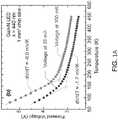
- an LED's forward voltagehas a significant variation with temperature.
- the forward LED voltage to maintain constant currentincreases with falling ambient temperatures. Over a temperature range of about 273 K to about 300 K, the forward voltage for a single LED increases by about 0.1 V.
- the total fluctuation in forward voltagecan reach several volts, depending on the number of LEDs in series, their temperature performance, and the total temperature drop.
- LED drivers supplied by constant voltage sourceswhich tend to be more efficient and less expensive than other power supplies, it may not be possible to increase the voltage to compensate for increases in LED forward voltage at low temperature.
- a linear LED driver supplied by an efficient constant-voltage power supplymight not provide enough voltage to drive LEDs arranged in series at extremely cold temperatures, such as typical cold-storage facility temperatures that run from -40°F (-40°C) to -4°F (-20°C).
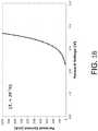
- LED drive currentalso varies with forward voltage as shown in FIG. 1B , which is a plot of forward current versus forward voltage (an I-V curve) for an LED at temperature of 25°C.
- the forward voltageshould exceed a characteristic on-voltage value, which typically is in the range of about 2-3 volts at room temperature as shown in FIG. 1B .
- Changing the LED temperaturecauses the current-voltage relationship to vary, in effect increasing or decreasing the LED voltage according to the relationship depicted in FIGS. 1A and 1B .
- knowledge of any two of these quantitiesmakes it possible to solve for the third quantity. For example, if the current is fixed (can be assumed to be fixed), a temperature measurement can be used to find the voltage, or vice versa.
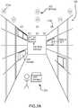
- FIG. 2Ashows LED-based lighting fixtures 210a and 210b (collectively, lighting fixtures 210) that uses the relationship among LED current, voltage, and temperature to operate in cold environments (e.g., environments at temperatures of 0° C, -5° C, -10° C, -15° C, -20° C, -25° C, -30° C, -35° C, -40° C, etc.).
- the fixturesuch as a refrigerated storage warehouse 200, with constant-voltage power supplies (not shown).
- Smaller fixtures 260can be used in smaller cold environments, such as the refrigerators 250 shown in FIG. 2B .
- each fixture 210includes a sensor that measures (decreases in) temperature.
- Each fixture 210also includes a processor or other circuitry that predicts the corresponding (increase in) LED forward voltage using the LEDs' temperature-voltage relationship at a given current.
- the lighting fixtures 210 and 260include bypass circuits that short circuit one or more of the LEDs in the lighting fixture 210 to reduce the overall forward voltage of the plurality of LEDs. Further, since LEDs are more efficient at producing light at low temperatures (e.g., below 0°C), so short-circuiting one or more LEDs may not significantly reduce the fixture's light output. In some cases, the bypass circuit may short-circuit the LED(s) to reduce power consumption for a given light output level at a given temperature.
- the LED fixturesmay regulate the current supplied by the driver circuit(s) to the LEDs.
- an exemplary LED fixturemay include a microcontroller or other processor that determines fluctuations in the LED drive current, possibly by measuring temperature or the current itself.
- the microcontrollermay modulate the drive current by applying a drive current control signal (e.g., a pulse-width modulated signal) to the gate of a bipolar transistor that conducts current from the power supply to the driver or from the driver to the LEDs.
- a drive current control signale.g., a pulse-width modulated signal
- the LED-based lighting fixtures 210can deliver light where and when needed, unlike HID and HIF fixtures, in part because of LEDs' fast response times.
- the LED fixture 210may include a processor that increases light output when there is activity 220 in the area 200 and dims the lights when the area 200 is unoccupied as indicated by a signal from an ambient light sensor (not shown).
- the processor 200may also brighten or dim the lights in response to a signal from an ambient light sensor to save energy in a process known as "daylight harvesting.”
- daylight harvestingFor more information on occupancy- and daylight-based LED control, see, e.g., the following patent documents, each of which is incorporated herein by reference in its respective entirety: U.S. Patent No. 8,536,802 ; U.S.
- Pre-Grant Publication No. 2012/0143357 A1U.S. Pre-Grant Publication No. 2012/0235579 A1 ; U.S. Pre-Grant Publication No. 2014/0028199 A1 ; and International Patent Application No. WO 2013/067389 .
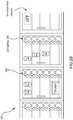
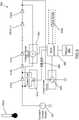
- FIG. 3Ashows a lighting fixture 300 that includes a plurality of LEDs 310a-310n (collectively, LEDs 310) that are in series with each other.
- the fixture 300may include 10, 11, 12, 13, 14, 15, or more LEDs 310 in series depending on the available voltage, which is supplied by a constant-voltage power supply 330 via a non-switching linear driver 340.
- the power supply 330provides 60 V or less (e.g., 42 V with a tolerance of ⁇ 0.5 V), it may be considered by Underwriters' Labs to be a Class 2 Power Unit and thus subject to slightly less rigorous design constraints than certain other power supplies.
- the linear driver 340may be optimized for a given temperature (e.g., roomtemperature), but fluctuations in ambient temperature may reduce the efficiency of the driver 340 and the LEDs 310.
- the lighting fixture 300also includes one or more sensors 360 capable of measuring temperature, voltage overhead, and/or LED current drive may sense the voltage provided for driving the LEDs 310.
- the fixture 300includes a microcontroller 350 or other processor, that determines, based on the sensor measurements, whether there is sufficient voltage to drive the LEDs 310.
- a bypass circuit 370shown in FIG. 3A as a switch, that short-circuits the first LED 310a if the voltage is too low to drive all of the LEDs 310.
- the sensor 360may be implemented as a fully-integrated digital temperature sensor like the one shown in FIG. 11 and described below.
- the sensor 360can also be implemented using other components, including but not limited to thermistors, thermocouples, and so forth.
- the sensor 360measures a decrease in temperature and predict an associated voltage increase by using a relationship, such as a look-up table stored in memory (not shown), that relates voltage with temperature.
- the sensor 360may measure a decrease in temperature and transmit a signal representing the measurement to a microcontroller 350 that uses the relationship relating LED forward voltage with temperature to determine the change in LED forward voltage at the lower temperature.
- the conversionis about -2.5mV/°C; for other LEDs, the conversion may be higher or lower.
- the microcontroller 350looks up the voltage-temperature conversion in a memory 352, which stores these characteristics in a look-up table or other representation of the LEDs' temperature-dependent current-voltage (I-V) characteristics.
- I-Vcurrent-voltage
- a voltmetermay be used to measure the voltage across the series, as discussed in more detail with respect to FIGS. 5 and 6 .
- the first LED 310a(or, equivalently, the last LED 310n) may be "bypassed" (e.g., short-circuited) to reduce the overall forward voltage of the LEDs 310. Bypassing one or more of the LEDs reduces the total forward voltage and makes it possible to drive at least some of the LEDs 310 at full current.
- the microcontroller 350may apply a "bypass-circuit" control signal (e.g., a pulse-width-modulated (PWM) digital signal) 380 to a bypass circuit 370 to effect the bypassing of the first LED 310a (or the last LED 310n) in the series 310.
- This bypass circuit 370may include a field-effect transistor or switching component in addition to various support components, e.g., as described below with respect to FIG. 10 . It can be implemented separately from the linear driver circuit 340 or located on the same circuit board as the linear driver circuit 340.
- the bypass-circuit 370Upon receiving the control signal 380, the bypass-circuit 370 short-circuits the first LED 310a and consequently reduce the overall forward voltage needed for the plurality of LEDs.
- the bypass circuit 370may be included in the linear driver 340, and the processor 350 may transmit the control signal directly to the linear driver 340.
- the first LED 310amay be checked periodically to determine if there is sufficient voltage available to drive all the LEDs 310. For example, if the temperature has increased, the power supply DC voltage may be adequate to provide a lower forward voltage to drive the LEDs 310.
- the microcontroller 350 and bypass-circuit 370may periodically enable the first LED 310a to check whether normal, un-bypassed operation has become possible. This periodic disabling of the bypass circuit may be performed at a rate too fast to observe with the naked eye, e.g., at a speed of 100 Hz or faster (i.e., a period less than about 20 milliseconds).
- the fast switching speedleads to an imperceptible flicker of the first LED 310a and possibly of the other LEDs 310 as well. If the measurement shows that the forward voltage has dropped below the supply voltage (e.g., because the temperature has risen), then the bypass circuit may re-enable the first LED 310. Otherwise, the bypass circuit may disable the first LED 310a after the measurement and check the voltage again later (e.g., every 30 seconds, 60 seconds, five minutes, ten minutes, etc.).
- FIG. 3Bshows how multiple "bypass circuits" 370a-370c (collectively, bypass circuits 370) may be coupled to the LEDs 310 to allow for individual "bypassing" of some or all of the LEDs.
- the bypass circuits 370may comprise respective transistors, e.g., as shown in FIG. 10 . Upon receiving a signal 380b from the microcontroller 350, some or all of these transistors may short out a respective LED 310.
- bypass circuit 370bis associated with LED 310b
- bypass circuit 370cis associated with LED 310c, etc.
- each bypass circuit 370is connected to the microcontroller 350.
- the microcontroller 350can switch on or disable the bypass circuits 370 individually and consequently can control the overall total voltage across the LEDs 310 more finely. This may allow the LEDs 310 to illuminate the environment over a wider range of voltage swings (and a wider range of temperatures).
- a lighting fixture 400may include light bars 490a-490c (collectively, light bars 490) that each comprise several LEDs 410a-410n (collectively, LEDs 410) in series.
- Each light bar 490may be connected to a constant-voltage power supply 430 through a respective low-voltage driver 440a-440c (collectively, drivers 440).
- the constant-voltage power supply 430 and low-voltage drivers 440may be commonly available modular power supplies and drivers, respectively.
- the low voltage drivers 440 of some or all of the light bars 410may serve as sensors that measure the temperature and/or voltage to determine if the forward voltage exceeds the DC voltage available for each light bar 490. For example, if the same amount of forward voltage should be available to each light bar 490 in the lighting fixture 400, the voltage drivers 440 may check to determine if the total forward voltage at each light bar 490 exceeds the total available DC voltage divided by the number of light bars 490 in the lighting fixture 400.
- the lighting fixture 400includes a digital light agent (DLA) module 450, which may be implemented as a processor, that may determine, upon receiving the sensing measurements from the voltage drivers 440, if the total forward voltages for the light bars 490 have exceeded the apportioned DC voltages.
- the voltage drivers 490may have made such determinations and may transmit the result to the DLA module 450.
- the DLA module 450may signal the voltage drivers to engage bypass circuits 420a-420c (collectively, bypass circuits 420) included in each light bar 490.
- the bypass circuits 420when engaged, may short-circuit at least one LED 410 in each light bar 490 ( FIG. 4 as shown depicts the short-circuiting of the first LED of the light bar).
- FIG. 4 as showndepicts the short-circuiting of the first LED of the light bar.
- the number of LEDs short-circuited by different bypass circuitsmay be the same and/or different.
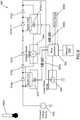
- FIG. 5shows a plurality of LEDs 510a-510n (collectively, LEDs 510) in series with each other and connected to a DC voltage power supply 530 via a non-switching linear driver 540.
- the linear drivermay be optimized for operation at a given temperature (e.g., roomtemperature), but fluctuations in ambient temperature may render the operation of the driver and the LEDs less efficient than the optimal case.
- a sensor 560bmeasures the ambient temperature 560a and determines whether there is sufficient voltage to drive the plurality of LEDs.
- the sensormay relay the measurements to the microcontroller 550 which may then look up, in a memory 552, a relationship that relates LED forward voltages with temperature to determine whether there is sufficient voltage to drive the plurality of LEDs.
- a voltmeter 590measures the voltage overhead across the plurality of the LEDs and may determine if the forward voltage of the plurality of LEDs exceeds the available DC voltage, and provide the microcontroller with the result.
- the sensor 590may measure the forward voltage of the plurality of LEDs and relay the measured data to the microcontroller 550 for the microcontroller to determine if the DC power supply provides sufficient voltage to drive the LEDs 510.
- the microcontroller 550Upon determining that the forward voltage has exceeded the power supply DC voltage and/or another prescribed voltage threshold, the microcontroller 550 applies a "bypass-circuit" control signal 580 (e.g., a pulse-width-modulated (PWM) digital signal) to the bypass circuit 570.
- PWMpulse-width-modulated
- bypass circuit 570This causes the bypass circuit 570 to short-circuit the first LED 510a (or last LED, as an alternative example) in the series as shown in FIG. 5 . As explained above, short-circuiting the first LED 510a reduces the overall forward voltage needed for the series of LEDs.
- the microcontroller 550may disable the bypass switch 570 and bring the shorted LED 510a back online periodically to check if there is enough forward voltage to drive all the LEDs 510.
- the ambient temperaturemay have increased and the required total forward voltage for the plurality of LEDs including the shorted-out LED may have been reduced to below the DC voltage.
- the microcontroller 550may periodically disable the "bypass circuit" (e.g., switch off the bypass circuit 570) to check whether un-bypassed operation has become possible by, for example, measuring the total forward voltage again with the voltmeter 590.
- This periodic disabling of the bypass circuitmay be performed at a rate too fast to observe with the naked eye, e.g., at a speed of 100 Hz or faster (i.e., a period less than about 20 milliseconds).
- the bypass circuitmay be disabled for a period less than about 20 milliseconds, 10 milliseconds, 5 milliseconds, etc.
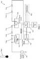
- FIG. 6shows a fixture 600 that includes multiple bypass circuits 620a and 620b (collectively, bypass circuits 620), each of which is coupled to a different LED 610 in the series of LEDs 610a-610n (collectively, LEDs 610).
- the LEDs 610are driven by a linear driver circuit 640 that receives power from a constant-voltage power supply 630.
- a processor 650determines the temperature by measuring the forward LED voltage with a voltage sense circuit 690 (e.g., a voltmeter) and looking up the temperature 660a corresponding to the measured voltage and drive current in a look-up table or other representation stored in a memory 652.
- a voltage sense circuit 690e.g., a voltmeter
- the processor 600may also measure the temperature 660a using a temperature sensor 660b and determine the LED forward voltage based on the temperature 660a.) If the processor 650 determines that the forward LED voltage has risen above the power supply voltage or another threshold, the processor generates one or more control signals 680a and 680b for actuating the bypass circuits 670a through 670(n - 1) (collectively, bypass circuits 670), only some of which are shown for clarity.
- bypass circuits 670a and 670bmay short-circuit the associated LED(s).
- the microcontroller 650can switch on or disable the bypass circuits 670 individually and consequently can control the overall total voltage across the LEDs 610 more finely. This may allow the LEDs 610 to illuminate the environment over a wider range of voltage swings (and a wider range of temperatures). This, for example, may also allow for the wear that ensues from the switching on/off of LEDs to be distributed evenly amongst some or all the LEDs in the series.
- the processor 650may actuate the bypass circuits 620a and 620b independently. That is, in FIG. 6 , the processor 650 can switch on or disable the bypass circuits 620a and 620b individually, and consequently would be able to control the voltage across each LED 610a, 610c separately. This, for example, may allow for the wear that ensues from the switching on/off of LEDs to be distributed evenly amongst some or all the LEDs in the series.
- FIG. 7illustrates an LED lighting fixture 700 with a processor 750 that controls the current supplied to LEDs 710 in response to changes in temperature.
- the LEDs 710are connected to a power supply (not shown) via a linear driver 740 and a bypass circuit 770, which may also be part of the linear driver 740.
- the linear driver 740can be an inexpensive device, e.g., a driver that does not provide or use a precision current reference for controlling the current supplied to the LEDs 710.
- the bypass circuit 770can be a transistor-based device like the bypass circuits shown in FIGS. 3A , 3B , 5 , 6 , 7 , and 10 . It can also comprise one or more bipolar transistors whose base-emitter voltage drop may be used to set a desired drive current for the LEDs 710.
- the processor 750 and the transistorsmanage the level of the drive current supplied to the LEDs 710.
- a current sensor 790 coupled in series with the LEDs 710may measure the LED drive current.
- the current sensor 790provides this measurement to the processor 750, which determines whether the drive current has deviated from a desired set-point based on values stored in a memory 752.
- the processor 750may also determine the voltage or temperature based on the current measurement.
- a temperature sensor 760bmay provide a measurement of the temperature 760a to the processor 750, which determines if the drive current has deviated from the desired drive current set-point based on the temperature measurement based on values stored in the memory 752.
- the sensor and/or the microcontrollermay use a relationship that relates current with temperature, and based on a temperature measurement from the sensor 760b may be able to determine the drive current at the plurality of LEDs 710.
- the processor 750may apply a drive current control signal (e.g., a pulse-width-modulated (PWM) digital signal) 780 to the bypass circuit 770 to adjust the drive current to the desired value. For example, if the ambient temperature drops and the output current exceeds the desired value, the processor 750 may apply a PWM signal to the transistor 770 in order to reduce the driver current to the set-point level. In some embodiments, the same PWM signal can also be used to dim the LEDs 710, e.g., in response to an occupancy event or a change in the ambient light level.
- PWMpulse-width-modulated
- FIG. 8shows an exemplary process for managing the voltage across LEDs operating in a low temperature environment.
- a plurality of LEDsare connected to a constant voltage source.
- the voltage sourcemay be a DC voltage source power supply connected to a linear driver.
- onemay measure physical quantities such as ambient temperature of the plurality of the LEDs, and determine, at step 803, the forward voltage of the LEDs by using a relationship that relates temperature to forward voltages.
- onemay measure the voltage overhead and/or LED current drive and determine the forward voltage.
- the measured drive voltageis compared to a threshold amount (e.g., the DC voltage provided by the voltage source). If the measured drive voltage is under the threshold, the temperature may be periodically monitored to check if the forward voltage remains under the threshold. If the measured forward voltage exceeds the threshold, at step 805, a processor (e.g., a microcontroller) may effectuate the bypassing of at least one of the LEDs in the plurality of LEDs using a bypass circuit. In some embodiments, the bypassing/short-circuiting may electrically isolate the LED and bring the overall forward voltage across the plurality of LEDs under the threshold.
- a threshold amounte.g., the DC voltage provided by the voltage source.
- the microcontrollermay disable the bypass circuit to determine if the LED forward voltage has dropped. For example, the temperature may have increased and the forward voltage required to drive the LEDs at the desired drive current may have decreased below the threshold. In some embodiments, the switching on/off of the bypass circuit may be undertaken at an imperceptible rate to humans. If a measurement of the forward voltage at step 807 shows that the forward voltage still exceeds the threshold, the bypass circuit is re-engaged and at least one LED is short-circuited at step 808. If, on the other hand, the forward voltage has fallen under the threshold, the bypass circuit is left disabled and the ambient temperature is monitored to check the forward voltage remains below the threshold.
- FIG. 9shows an exemplary process for managing the drive current supplied to a plurality of LEDs operating in a low temperature environment.
- a constant voltage supplyis connected to a plurality of LEDs via a linear driver to maintain a given drive current through the plurality of LEDs.
- physical quantitiessuch as ambient temperature of the plurality of the LEDs are measured, and based on the measurements, at step 903, the drive current at the LEDs, and the variations due to fluctuations in temperature may be determined. For example, a drop in temperature may result in an increase in the drive current, and such a change in the drive current may be determined at step 903.
- the fluctuations in drive currentmay also be determined by measuring the current itself and/or voltage overhead using a sensor.
- the temperaturemay be periodically monitored to check if the drive current variations remains within the bounds. If, on the other hand, the current variations are not acceptable, a microcontroller may apply, at step 905, a drive current control signal to a transistor and/or a linear driver circuit to keep the current at the desired level of drive current. For example, if a drop in temperature has resulted in an increase of the drive current, the microprocessor may signal the transistor and/or the linear driver to reduce the drive current to the desired level.
- step 906one may determine if the drive current has attained the desired level, and if so, at step 907, the temperature may be periodically monitored to check the drive current maintains at the desired level. If, on the other hand, the drive current has not reached the desired level, the microcontroller may apply additional signal to the transistor and/or linear driver to adjust the drive current at the plurality of LEDs to the desired level.
- FIG. 10shows a circuit diagram of an exemplary bypass circuit 1000.
- the bypass circuit 1000includes a metal-oxide-scmiconductor field-effect transistor (MOSFET) 1020 that is connected to a DC voltage power supply 1030.
- the voltage supply 1030may be a constant-voltage source (e.g., 42V).
- the MOSFET 1020is also connected to a bipolar junction transistor 1070 whose base is connected to a microcontroller or other processor (not shown).
- the bypass circuit 1000also contains several resistors, which may be connected to the transistors in series and/or parallel for use in, amongst other things, monitoring and/or testing the bypass circuit 1000.
- the MOSFET 1020may be connected to a resistor R1 in parallel, and the transistor 107 0 may be connected to a smaller resistor R37 in series.
- a much higher resistor R33may be placed between the gate of the MOSFET 1020 and the collector of the transistor 1070.
- the monitoring and/or testingmay be conduct at several points throughout the circuit. For example, in the embodiments depicted in FIG. 10 , several test points (TPs), such as TP23, TP24, TP21, TP28 and/or TP27 are used to determine voltage and/or current in the bypass circuit.
- TPstest points
- FIG. 11shows a circuit diagram of an exemplary temperature sensor.
- the temperature sensor 1100comprises a thermal sensor 1120 capable of measuring its own internal temperature and the temperature of a remote/external component such as a transistor, diode, LED, etc.
- the thermal sensor 1120comprises a digital temperature supervisor; in other examples, the thermal sensor 1120 may comprise a thermocouple, thermistor, or other suitable temperature-sensitive device or component.
- the thermal sensor 1120may measure the temperature using a transistor 1170. Such a thermal sensor may have an effective capacitance C14.
- the measurements of the temperature sensor 1100may be communicated to a microcontroller 1150 via a suitable electrical connection as depicted in FIG. 11 .
Landscapes
- Circuit Arrangement For Electric Light Sources In General (AREA)
Description
- Compared to traditional lighting systems such as high intensity discharge (HID), high intensity fluorescent (HIF), and high pressure sodium (HPS) lightings that are used in a variety of settings, including large scale facilities such as warehouses, light emitting diodes (LEDs) provide superior performance. Some of the advantages include low energy consumption (with excellent lighting levels), fast switching, long lifetime, etc.
- In
US2012/262074 , a driving circuit of light emitting diodes includes a power supply circuit, at least one bypass circuit, and a temperature control circuit. - In accordance with one aspect of the invention, there is provided a lighting fixture as defined by
claim 1 and a method of operating a plurality of light emitting diodes arranged in series at low temperature as defined byclaim 5. Optional features are defined by the dependent claims. - The skilled artisan will understand that the drawings primarily are for illustrative purposes and are not intended to limit the scope of the inventive subject matter described herein. The drawings are not necessarily to scale; in some instances, various aspects of the inventive subject matter disclosed herein may be shown exaggerated or enlarged in the drawings to facilitate an understanding of different features. In the drawings, like reference characters generally refer to like features (e.g., functionally similar and/or structurally similar elements).
FIG. 1A shows a plot of the dependence of forward voltage on temperature for an exemplary light emitting diode.FIG. 1B shows the current versus voltage diagram of an LED,FIG. 2A shows an exemplary LED lighting system in a cold-storage facility.FIG. 2B shows an exemplary lighting system in the freezer section of a supermarket.FIG. 3A shows an exemplary bypass circuit regulating, in response to a drop in temperature as measured by a sensor, the voltage available to a plurality of LEDs by short-circuiting one of the LEDs in the plurality of LEDs.FIG. 3B shows an exemplary lighting fixture that includes several LED light bars connected to a direct current (DC) power supply through respective low-voltage drivers and a bypass circuit.FIG. 4 shows an exemplary bypass circuit regulating the voltage available to a plurality of LEDs in response to an increase in series voltage due to a drop in temperature by short-circuiting an LED in the plurality of LEDs.FIG. 5 shows an exemplary bypass circuit regulating, in response to a drop in temperature as measured by a sensor, the voltage available to a plurality of LEDs by short-circuiting any number of LEDs in the plurality of LEDs.FIG. 6 shows an exemplary bypass circuit regulating the amount of voltage available to a plurality of LEDs in response to an increase in series voltage due to a drop in temperature by short-circuiting any number of LEDs in the plurality of LEDs.FIG. 7 shows an exemplary bypass circuit regulating, in response to a drop in temperature, the amount of drive current available to a plurality of LEDs by switching a transistor using a drive current control signal.FIG. 8 shows a flow diagram of an exemplary process for managing the voltage across LEDs operating in a low temperature environment.FIG. 9 shows a flow diagram of an exemplary process for managing the current supplied to a plurality of LEDs operating in a low temperature environment.FIG. 10 is a circuit diagram that shows an exemplary bypass circuit.FIG. 11 is a circuit diagram that shows an exemplary temperature sensor.- For the cold storage industry, facility lighting has been a significant challenge owing to the subpar performance in refrigerated environments of the main industrial lighting choices, high intensity discharge (HID) and high intensity fluorescent (HIF) lighting fixtures. In general, these lighting systems consume too much energy, generate too much heat, and are expensive to maintain. And low-temperature environments, such as those in cold-storage facilities, exacerbate the disadvantages of HID and HIF lighting.
- In contrast, an exemplary smart light-emitting diode (LED) lighting fixture offers consistent performance and durability in all temperature environments. For example, an LED lighting system can frequently cycle on/off without impacting the longevity of the lamp source or fixture, instantly return to full intensity when activated, even in -40°F chillers, and generate minimal heat during operations, significantly reducing refrigeration loads.
- However, an LED's forward voltage has a significant variation with temperature. For example, as shown in
FIG. 1A for the specific example of a GaInN LEDs the forward LED voltage to maintain constant current increases with falling ambient temperatures. Over a temperature range of about 273 K to about 300 K, the forward voltage for a single LED increases by about 0.1 V. For strings of LEDs arranged in series, the total fluctuation in forward voltage can reach several volts, depending on the number of LEDs in series, their temperature performance, and the total temperature drop. Unfortunately, for LED drivers supplied by constant voltage sources, which tend to be more efficient and less expensive than other power supplies, it may not be possible to increase the voltage to compensate for increases in LED forward voltage at low temperature. In other words, a linear LED driver supplied by an efficient constant-voltage power supply might not provide enough voltage to drive LEDs arranged in series at extremely cold temperatures, such as typical cold-storage facility temperatures that run from -40°F (-40°C) to -4°F (-20°C). - LED drive current also varies with forward voltage as shown in
FIG. 1B , which is a plot of forward current versus forward voltage (an I-V curve) for an LED at temperature of 25°C. For an LED to emit an appreciable amount of light, the forward voltage should exceed a characteristic on-voltage value, which typically is in the range of about 2-3 volts at room temperature as shown inFIG. 1B . Changing the LED temperature causes the current-voltage relationship to vary, in effect increasing or decreasing the LED voltage according to the relationship depicted inFIGS. 1A and1B . But because an LED's voltage, current, and temperature are interrelated, knowledge of any two of these quantities makes it possible to solve for the third quantity. For example, if the current is fixed (can be assumed to be fixed), a temperature measurement can be used to find the voltage, or vice versa. FIG. 2A shows LED-basedlighting fixtures storage warehouse 200, with constant-voltage power supplies (not shown).Smaller fixtures 260 can be used in smaller cold environments, such as therefrigerators 250 shown inFIG. 2B .- As explained in greater detail below, each fixture 210 includes a sensor that measures (decreases in) temperature. Each fixture 210 also includes a processor or other circuitry that predicts the corresponding (increase in) LED forward voltage using the LEDs' temperature-voltage relationship at a given current. To compensate for changes in LED forward voltage, the
lighting fixtures 210 and 260 include bypass circuits that short circuit one or more of the LEDs in the lighting fixture 210 to reduce the overall forward voltage of the plurality of LEDs. Further, since LEDs are more efficient at producing light at low temperatures (e.g., below 0°C), so short-circuiting one or more LEDs may not significantly reduce the fixture's light output. In some cases, the bypass circuit may short-circuit the LED(s) to reduce power consumption for a given light output level at a given temperature. - In other cases, the LED fixtures may regulate the current supplied by the driver circuit(s) to the LEDs. For instance, an exemplary LED fixture may include a microcontroller or other processor that determines fluctuations in the LED drive current, possibly by measuring temperature or the current itself. The microcontroller may modulate the drive current by applying a drive current control signal (e.g., a pulse-width modulated signal) to the gate of a bipolar transistor that conducts current from the power supply to the driver or from the driver to the LEDs.
- In addition, the LED-based lighting fixtures 210 can deliver light where and when needed, unlike HID and HIF fixtures, in part because of LEDs' fast response times. For instance, the LED fixture 210 may include a processor that increases light output when there is
activity 220 in thearea 200 and dims the lights when thearea 200 is unoccupied as indicated by a signal from an ambient light sensor (not shown). Theprocessor 200 may also brighten or dim the lights in response to a signal from an ambient light sensor to save energy in a process known as "daylight harvesting." For more information on occupancy- and daylight-based LED control, see, e.g., the following patent documents, each of which is incorporated herein by reference in its respective entirety:U.S. Patent No. 8,536,802 ;U.S. Pre-Grant Publication No. 2012/0143357 A1 ;U.S. Pre-Grant Publication No. 2012/0235579 A1 ;U.S. Pre-Grant Publication No. 2014/0028199 A1 ; and International Patent Application No.WO 2013/067389 . FIG. 3A shows alighting fixture 300 that includes a plurality ofLEDs 310a-310n (collectively, LEDs 310) that are in series with each other. For instance, thefixture 300 may include 10, 11, 12, 13, 14, 15, ormore LEDs 310 in series depending on the available voltage, which is supplied by a constant-voltage power supply 330 via a non-switchinglinear driver 340. If thepower supply 330 provides 60 V or less (e.g., 42 V with a tolerance of ± 0.5 V), it may be considered by Underwriters' Labs to be aClass 2 Power Unit and thus subject to slightly less rigorous design constraints than certain other power supplies.- The
linear driver 340 may be optimized for a given temperature (e.g., roomtemperature), but fluctuations in ambient temperature may reduce the efficiency of thedriver 340 and theLEDs 310. Thelighting fixture 300 also includes one ormore sensors 360 capable of measuring temperature, voltage overhead, and/or LED current drive may sense the voltage provided for driving theLEDs 310. And thefixture 300 includes amicrocontroller 350 or other processor, that determines, based on the sensor measurements, whether there is sufficient voltage to drive theLEDs 310. Abypass circuit 370, shown inFIG. 3A as a switch, that short-circuits thefirst LED 310a if the voltage is too low to drive all of theLEDs 310. - For example, the
sensor 360 may be implemented as a fully-integrated digital temperature sensor like the one shown inFIG. 11 and described below. Thesensor 360 can also be implemented using other components, including but not limited to thermistors, thermocouples, and so forth. In operation, thesensor 360 measures a decrease in temperature and predict an associated voltage increase by using a relationship, such as a look-up table stored in memory (not shown), that relates voltage with temperature. As an alternative embodiment, thesensor 360 may measure a decrease in temperature and transmit a signal representing the measurement to amicrocontroller 350 that uses the relationship relating LED forward voltage with temperature to determine the change in LED forward voltage at the lower temperature. For Cree LEDs, the conversion is about -2.5mV/°C; for other LEDs, the conversion may be higher or lower. In this case, themicrocontroller 350 looks up the voltage-temperature conversion in amemory 352, which stores these characteristics in a look-up table or other representation of the LEDs' temperature-dependent current-voltage (I-V) characteristics. (In other embodiments, a voltmeter may be used to measure the voltage across the series, as discussed in more detail with respect toFIGS. 5 and6 .) - If the
sensor 360 and/orprocessor 350 determine that there is not sufficient voltage and/or there is a requirement that the forward voltage should not exceed a prescribed amount (e.g., to protect the integrity of the LEDs), thefirst LED 310a (or, equivalently, thelast LED 310n) may be "bypassed" (e.g., short-circuited) to reduce the overall forward voltage of theLEDs 310. Bypassing one or more of the LEDs reduces the total forward voltage and makes it possible to drive at least some of theLEDs 310 at full current. - In some implementations, the
microcontroller 350 may apply a "bypass-circuit" control signal (e.g., a pulse-width-modulated (PWM) digital signal) 380 to abypass circuit 370 to effect the bypassing of thefirst LED 310a (or thelast LED 310n) in theseries 310. Thisbypass circuit 370 may include a field-effect transistor or switching component in addition to various support components, e.g., as described below with respect toFIG. 10 . It can be implemented separately from thelinear driver circuit 340 or located on the same circuit board as thelinear driver circuit 340. Upon receiving thecontrol signal 380, the bypass-circuit 370 short-circuits thefirst LED 310a and consequently reduce the overall forward voltage needed for the plurality of LEDs. (In alternative implementations, thebypass circuit 370 may be included in thelinear driver 340, and theprocessor 350 may transmit the control signal directly to thelinear driver 340.) - Once the
first LED 310a has been electrically removed (short-circuited) from the series ofLEDs 310, it may be checked periodically to determine if there is sufficient voltage available to drive all theLEDs 310. For example, if the temperature has increased, the power supply DC voltage may be adequate to provide a lower forward voltage to drive theLEDs 310. In such embodiments, themicrocontroller 350 and bypass-circuit 370 may periodically enable thefirst LED 310a to check whether normal, un-bypassed operation has become possible. This periodic disabling of the bypass circuit may be performed at a rate too fast to observe with the naked eye, e.g., at a speed of 100 Hz or faster (i.e., a period less than about 20 milliseconds). The fast switching speed leads to an imperceptible flicker of thefirst LED 310a and possibly of theother LEDs 310 as well. If the measurement shows that the forward voltage has dropped below the supply voltage (e.g., because the temperature has risen), then the bypass circuit may re-enable thefirst LED 310. Otherwise, the bypass circuit may disable thefirst LED 310a after the measurement and check the voltage again later (e.g., every 30 seconds, 60 seconds, five minutes, ten minutes, etc.). FIG. 3B shows how multiple "bypass circuits" 370a-370c (collectively, bypass circuits 370) may be coupled to theLEDs 310 to allow for individual "bypassing" of some or all of the LEDs. For example, thebypass circuits 370 may comprise respective transistors, e.g., as shown inFIG. 10 . Upon receiving asignal 380b from themicrocontroller 350, some or all of these transistors may short out arespective LED 310. For example, inFIG. 3B ,bypass circuit 370b is associated withLED 310b,bypass circuit 370c is associated withLED 310c, etc., and eachbypass circuit 370 is connected to themicrocontroller 350. As such, themicrocontroller 350 can switch on or disable thebypass circuits 370 individually and consequently can control the overall total voltage across theLEDs 310 more finely. This may allow theLEDs 310 to illuminate the environment over a wider range of voltage swings (and a wider range of temperatures).- With reference to
FIG. 4 , alighting fixture 400 may includelight bars 490a-490c (collectively, light bars 490) that each compriseseveral LEDs 410a-410n (collectively, LEDs 410) in series. Each light bar 490 may be connected to a constant-voltage power supply 430 through a respective low-voltage driver 440a-440c (collectively, drivers 440). In some embodiments, the constant-voltage power supply 430 and low-voltage drivers 440 may be commonly available modular power supplies and drivers, respectively. - As explained above, the combined forward voltages of the LEDs 410 in each light bar 490 may exceed the available DC voltage as the ambient temperature drops. In some implementations, the low voltage drivers 440 of some or all of the light bars 410 may serve as sensors that measure the temperature and/or voltage to determine if the forward voltage exceeds the DC voltage available for each light bar 490. For example, if the same amount of forward voltage should be available to each light bar 490 in the
lighting fixture 400, the voltage drivers 440 may check to determine if the total forward voltage at each light bar 490 exceeds the total available DC voltage divided by the number of light bars 490 in thelighting fixture 400. - In some embodiments, the
lighting fixture 400 includes a digital light agent (DLA)module 450, which may be implemented as a processor, that may determine, upon receiving the sensing measurements from the voltage drivers 440, if the total forward voltages for the light bars 490 have exceeded the apportioned DC voltages. In other embodiments, the voltage drivers 490 may have made such determinations and may transmit the result to theDLA module 450. Once it has been determined that the forward voltages at one or more of the light bars exceed the available DC voltage, and/or the total combined forward voltage of all the LEDs 410 exceeds the power supply DC voltage, theDLA module 450 may signal the voltage drivers to engagebypass circuits 420a-420c (collectively, bypass circuits 420) included in each light bar 490. In some embodiments, when engaged, the bypass circuits 420 may short-circuit at least one LED 410 in each light bar 490 (FIG. 4 as shown depicts the short-circuiting of the first LED of the light bar). For example, the number of LEDs short-circuited by different bypass circuits may be the same and/or different. FIG. 5 shows a plurality ofLEDs 510a-510n (collectively, LEDs 510) in series with each other and connected to a DCvoltage power supply 530 via a non-switchinglinear driver 540. The linear driver may be optimized for operation at a given temperature (e.g., roomtemperature), but fluctuations in ambient temperature may render the operation of the driver and the LEDs less efficient than the optimal case. In embodiments similar to those discussed with reference toFIG. 3A , asensor 560b measures theambient temperature 560a and determines whether there is sufficient voltage to drive the plurality of LEDs. In alternative embodiments, the sensor may relay the measurements to themicrocontroller 550 which may then look up, in amemory 552, a relationship that relates LED forward voltages with temperature to determine whether there is sufficient voltage to drive the plurality of LEDs.- In other embodiments, a
voltmeter 590 measures the voltage overhead across the plurality of the LEDs and may determine if the forward voltage of the plurality of LEDs exceeds the available DC voltage, and provide the microcontroller with the result. In some embodiments, thesensor 590 may measure the forward voltage of the plurality of LEDs and relay the measured data to themicrocontroller 550 for the microcontroller to determine if the DC power supply provides sufficient voltage to drive theLEDs 510. Upon determining that the forward voltage has exceeded the power supply DC voltage and/or another prescribed voltage threshold, themicrocontroller 550 applies a "bypass-circuit" control signal 580 (e.g., a pulse-width-modulated (PWM) digital signal) to thebypass circuit 570. This causes thebypass circuit 570 to short-circuit thefirst LED 510a (or last LED, as an alternative example) in the series as shown inFIG. 5 . As explained above, short-circuiting thefirst LED 510a reduces the overall forward voltage needed for the series of LEDs. - After the
first LED 510a has been short-circuited and the total forward voltage of the remaining plurality of LEDs reduced to or below the DC voltage from thepower supply 530, themicrocontroller 550 may disable thebypass switch 570 and bring the shortedLED 510a back online periodically to check if there is enough forward voltage to drive all theLEDs 510. For example, the ambient temperature may have increased and the required total forward voltage for the plurality of LEDs including the shorted-out LED may have been reduced to below the DC voltage. In such embodiments, themicrocontroller 550 may periodically disable the "bypass circuit" (e.g., switch off the bypass circuit 570) to check whether un-bypassed operation has become possible by, for example, measuring the total forward voltage again with thevoltmeter 590. This periodic disabling of the bypass circuit may be performed at a rate too fast to observe with the naked eye, e.g., at a speed of 100 Hz or faster (i.e., a period less than about 20 milliseconds). For example, the bypass circuit may be disabled for a period less than about 20 milliseconds, 10 milliseconds, 5 milliseconds, etc. FIG. 6 shows afixture 600 that includes multiple bypass circuits 620a and 620b (collectively, bypass circuits 620), each of which is coupled to adifferent LED 610 in the series ofLEDs 610a-610n (collectively, LEDs 610). TheLEDs 610 are driven by alinear driver circuit 640 that receives power from a constant-voltage power supply 630. As inFIG. 5 , aprocessor 650 determines the temperature by measuring the forward LED voltage with a voltage sense circuit 690 (e.g., a voltmeter) and looking up thetemperature 660a corresponding to the measured voltage and drive current in a look-up table or other representation stored in amemory 652. (Theprocessor 600 may also measure thetemperature 660a using atemperature sensor 660b and determine the LED forward voltage based on thetemperature 660a.) If theprocessor 650 determines that the forward LED voltage has risen above the power supply voltage or another threshold, the processor generates one ormore control signals - Upon receiving the
control signals microcontroller 650, the bypass circuits 670a and 670b may short-circuit the associated LED(s). For example, inFIG. 6 , bypass circuit/switch 670a is associated withLED 610a, bypass circuit/switch 670b is associated withLED 610b, etc. As such, themicrocontroller 650 can switch on or disable thebypass circuits 670 individually and consequently can control the overall total voltage across theLEDs 610 more finely. This may allow theLEDs 610 to illuminate the environment over a wider range of voltage swings (and a wider range of temperatures). This, for example, may also allow for the wear that ensues from the switching on/off of LEDs to be distributed evenly amongst some or all the LEDs in the series. - If desired, the
processor 650 may actuate the bypass circuits 620a and 620b independently. That is, inFIG. 6 , theprocessor 650 can switch on or disable the bypass circuits 620a and 620b individually, and consequently would be able to control the voltage across eachLED FIG. 7 illustrates anLED lighting fixture 700 with aprocessor 750 that controls the current supplied toLEDs 710 in response to changes in temperature. TheLEDs 710 are connected to a power supply (not shown) via alinear driver 740 and abypass circuit 770, which may also be part of thelinear driver 740. In this case, thelinear driver 740 can be an inexpensive device, e.g., a driver that does not provide or use a precision current reference for controlling the current supplied to theLEDs 710. And thebypass circuit 770 can be a transistor-based device like the bypass circuits shown inFIGS. 3A ,3B ,5 ,6 ,7 , and10 . It can also comprise one or more bipolar transistors whose base-emitter voltage drop may be used to set a desired drive current for theLEDs 710. In operation, theprocessor 750 and the transistors manage the level of the drive current supplied to theLEDs 710.- As shown in
FIG. 7 , acurrent sensor 790 coupled in series with theLEDs 710 may measure the LED drive current. Thecurrent sensor 790 provides this measurement to theprocessor 750, which determines whether the drive current has deviated from a desired set-point based on values stored in amemory 752. Theprocessor 750 may also determine the voltage or temperature based on the current measurement. - In other embodiments, a
temperature sensor 760b may provide a measurement of thetemperature 760a to theprocessor 750, which determines if the drive current has deviated from the desired drive current set-point based on the temperature measurement based on values stored in thememory 752. For example, the sensor and/or the microcontroller may use a relationship that relates current with temperature, and based on a temperature measurement from thesensor 760b may be able to determine the drive current at the plurality ofLEDs 710. - Upon determining the deviation of the drive current from the drive current set-point, in some embodiments, the
processor 750 may apply a drive current control signal (e.g., a pulse-width-modulated (PWM) digital signal) 780 to thebypass circuit 770 to adjust the drive current to the desired value. For example, if the ambient temperature drops and the output current exceeds the desired value, theprocessor 750 may apply a PWM signal to thetransistor 770 in order to reduce the driver current to the set-point level. In some embodiments, the same PWM signal can also be used to dim theLEDs 710, e.g., in response to an occupancy event or a change in the ambient light level. FIG. 8 shows an exemplary process for managing the voltage across LEDs operating in a low temperature environment. In some embodiments, atstep 801, a plurality of LEDs are connected to a constant voltage source. For example, the voltage source may be a DC voltage source power supply connected to a linear driver. Atstep 802, one may measure physical quantities such as ambient temperature of the plurality of the LEDs, and determine, atstep 803, the forward voltage of the LEDs by using a relationship that relates temperature to forward voltages. In other embodiments, one may measure the voltage overhead and/or LED current drive and determine the forward voltage.- At
step 804, the measured drive voltage is compared to a threshold amount (e.g., the DC voltage provided by the voltage source). If the measured drive voltage is under the threshold, the temperature may be periodically monitored to check if the forward voltage remains under the threshold. If the measured forward voltage exceeds the threshold, at step 805, a processor (e.g., a microcontroller) may effectuate the bypassing of at least one of the LEDs in the plurality of LEDs using a bypass circuit. In some embodiments, the bypassing/short-circuiting may electrically isolate the LED and bring the overall forward voltage across the plurality of LEDs under the threshold. - At
step 806, the microcontroller may disable the bypass circuit to determine if the LED forward voltage has dropped. For example, the temperature may have increased and the forward voltage required to drive the LEDs at the desired drive current may have decreased below the threshold. In some embodiments, the switching on/off of the bypass circuit may be undertaken at an imperceptible rate to humans. If a measurement of the forward voltage atstep 807 shows that the forward voltage still exceeds the threshold, the bypass circuit is re-engaged and at least one LED is short-circuited atstep 808. If, on the other hand, the forward voltage has fallen under the threshold, the bypass circuit is left disabled and the ambient temperature is monitored to check the forward voltage remains below the threshold. FIG. 9 shows an exemplary process for managing the drive current supplied to a plurality of LEDs operating in a low temperature environment. Atstep 901, a constant voltage supply is connected to a plurality of LEDs via a linear driver to maintain a given drive current through the plurality of LEDs. Atstep 902, physical quantities such as ambient temperature of the plurality of the LEDs are measured, and based on the measurements, atstep 903, the drive current at the LEDs, and the variations due to fluctuations in temperature may be determined. For example, a drop in temperature may result in an increase in the drive current, and such a change in the drive current may be determined atstep 903. In some embodiments, the fluctuations in drive current may also be determined by measuring the current itself and/or voltage overhead using a sensor.- At
step 904, if the drive current is determined to be acceptable (e.g., the drive current variations are within some acceptable bounds of the desired drive current set-point), the temperature may be periodically monitored to check if the drive current variations remains within the bounds. If, on the other hand, the current variations are not acceptable, a microcontroller may apply, at step 905, a drive current control signal to a transistor and/or a linear driver circuit to keep the current at the desired level of drive current. For example, if a drop in temperature has resulted in an increase of the drive current, the microprocessor may signal the transistor and/or the linear driver to reduce the drive current to the desired level. Atstep 906, one may determine if the drive current has attained the desired level, and if so, atstep 907, the temperature may be periodically monitored to check the drive current maintains at the desired level. If, on the other hand, the drive current has not reached the desired level, the microcontroller may apply additional signal to the transistor and/or linear driver to adjust the drive current at the plurality of LEDs to the desired level. FIG. 10 shows a circuit diagram of anexemplary bypass circuit 1000. Thebypass circuit 1000 includes a metal-oxide-scmiconductor field-effect transistor (MOSFET) 1020 that is connected to a DCvoltage power supply 1030. For example, thevoltage supply 1030 may be a constant-voltage source (e.g., 42V). TheMOSFET 1020 is also connected to abipolar junction transistor 1070 whose base is connected to a microcontroller or other processor (not shown). In some embodiments, thebypass circuit 1000 also contains several resistors, which may be connected to the transistors in series and/or parallel for use in, amongst other things, monitoring and/or testing thebypass circuit 1000. For example, theMOSFET 1020 may be connected to a resistor R1 in parallel, and the transistor 107 0 may be connected to a smaller resistor R37 in series. In some embodiments, a much higher resistor R33 may be placed between the gate of theMOSFET 1020 and the collector of thetransistor 1070. In some embodiments, the monitoring and/or testing may be conduct at several points throughout the circuit. For example, in the embodiments depicted inFIG. 10 , several test points (TPs), such as TP23, TP24, TP21, TP28 and/or TP27 are used to determine voltage and/or current in the bypass circuit.FIG. 11 shows a circuit diagram of an exemplary temperature sensor. In some embodiments, thetemperature sensor 1100 comprises athermal sensor 1120 capable of measuring its own internal temperature and the temperature of a remote/external component such as a transistor, diode, LED, etc. In this case, thethermal sensor 1120 comprises a digital temperature supervisor; in other examples, thethermal sensor 1120 may comprise a thermocouple, thermistor, or other suitable temperature-sensitive device or component. In some embodiments, thethermal sensor 1120 may measure the temperature using a transistor 1170. Such a thermal sensor may have an effective capacitance C14. The measurements of thetemperature sensor 1100 may be communicated to a microcontroller 1150 via a suitable electrical connection as depicted inFIG. 11 .
Claims (13)
- A lighting fixture (300, 500, 600, 700) comprising:a plurality of light emitting diodes (310, 510, 610, 710) arranged in series, the plurality of light emitting diodes comprising at least one first light emitting diode;a constant-voltage power supply (330, 530, 630, 730), operably coupled to the plurality of light emitting diodes, to provide a constant voltage across the plurality of light emitting diodes;a sensor (360, 560, 660, 760), in electrical communication with the plurality of light emitting diodes, to measure a decrease in temperature of the plurality of light emitting diodes, the decrease in temperature of the plurality of light emitting diodes causing an increase in series voltage across the plurality of light emitting diodes; anda bypass circuit (370, 570, 670, 770), operably coupled to the sensor, to short-circuit the at least one first light emitting diode in response to the increase in the series voltage so as to reduce the series voltage below the constant voltage provided by the constant-voltage power supply,wherein the sensor is configured to measure a change in the temperature of the plurality of light emitting diodes while the at least one first light emitting diode is enabled,characterised in thatthe bypass circuit is configured to enable the at least one first light emitting diode for a predetermined period after disabling the at least one first light emitting diode in response to the increase in the series voltage.
- The apparatus of claim 1, wherein the predetermined period is less than about 20 milliseconds.
- The apparatus of any of the preceding claims, wherein the bypass circuit is configured to short-circuit the at least one first light emitting diode after the sensor has measured the change in temperature of the plurality of light emitting diodes.
- The apparatus of any of the preceding claims, wherein the bypass circuit is configured to short-circuit the at least one first light emitting diode if the series voltage exceeds a threshold voltage.
- A method of operating a plurality of light emitting diodes arranged in series at low temperature, the method comprising:(A) providing, via a constant-voltage power supply operably coupled to the plurality of light emitting diodes, a constant voltage across the plurality of light emitting diodes;(B) measuring, with a sensor in electrical communication with the plurality of light emitting diodes, a decrease in the temperature of the plurality of light emitting diodes, the decrease in temperature of the plurality of light emitting diodes corresponding to an increase in series voltage across the plurality of light emitting diodes;(C) short-circuiting, with a bypass circuit operably coupled to the sensor, at least one first light emitting diode in the plurality of light emitting diodes in response to the increase in the series voltage so as to reduce the series voltage below the constant voltage provided by the constant-voltage power supply;characterised by further comprising:(D) after (C), enabling for a predetermined time with the bypass circuit, the at least one first light emitting diode; and(E) measuring, with the sensor, a change in the temperature of the plurality of light emitting diodes while the at least one first light emitting diode is enabled.
- The method of claim 5, wherein (D) comprises enabling the at least one first light emitting diode for a period less than about 20 milliseconds.
- The method of either of claims 5 or 6, further comprising:(F) short-circuiting, with the bypass circuit, the at least one first light emitting diode after measuring the change in the temperature of the plurality of light emitting diodes.
- The method of any of claims 5-7, comprising:disabling the at least one first light emitting diode if the series voltage exceeds the constant voltage provided by the constant-voltage power supply.
- The apparatus of claim 4, wherein the threshold voltage is the constant voltage provided by the constant-voltage power supply.
- The apparatus of claim 4, wherein the bypass circuit is configured to periodically enable and disable the at least one first light emitting diode at a speed of 100 Hz or faster.
- The apparatus of any of claims 1-4, 9, and 10, wherein the sensor comprises at least one of a digital temperature supervisor, a thermocouple, a thermistor, and a transistor.
- The apparatus of any of claims 1-4 and 9-11, wherein the apparatus is configured for operation at temperatures from -40°C to 0°C.
- The apparatus of any of claims 1-4 and 9-12, further comprising a processor (350, 550, 650, 750), operably coupled to the sensor and the bypass circuit, to determine the increase in series voltage based on the decrease in temperature of the plurality of light emitting diodes and control the bypass circuit to short-circuit the at least one first light emitting diode based on the increase in the series voltage so as to reduce the series voltage below the constant voltage provided by the constant-voltage power supply.
Applications Claiming Priority (2)
| Application Number | Priority Date | Filing Date | Title |
|---|---|---|---|
| US201361817671P | 2013-04-30 | 2013-04-30 | |
| PCT/US2014/035990WO2014179379A1 (en) | 2013-04-30 | 2014-04-30 | Operating light emitting diodes at low temperature |
Publications (3)
| Publication Number | Publication Date |
|---|---|
| EP2992395A1 EP2992395A1 (en) | 2016-03-09 |
| EP2992395A4 EP2992395A4 (en) | 2016-12-28 |
| EP2992395B1true EP2992395B1 (en) | 2018-03-07 |
Family
ID=51843909
Family Applications (1)
| Application Number | Title | Priority Date | Filing Date |
|---|---|---|---|
| EP14791232.3AActiveEP2992395B1 (en) | 2013-04-30 | 2014-04-30 | Operating light emitting diodes at low temperature |
Country Status (5)
| Country | Link |
|---|---|
| US (2) | US9924576B2 (en) |
| EP (1) | EP2992395B1 (en) |
| AU (2) | AU2014259974B2 (en) |
| CA (1) | CA2910222C (en) |
| WO (1) | WO2014179379A1 (en) |
Families Citing this family (13)
| Publication number | Priority date | Publication date | Assignee | Title |
|---|---|---|---|---|
| US20120235579A1 (en) | 2008-04-14 | 2012-09-20 | Digital Lumens, Incorporated | Methods, apparatus and systems for providing occupancy-based variable lighting |
| US10539311B2 (en) | 2008-04-14 | 2020-01-21 | Digital Lumens Incorporated | Sensor-based lighting methods, apparatus, and systems |
| EP3517839B1 (en) | 2010-11-04 | 2021-09-22 | Digital Lumens Incorporated | Method, apparatus, and system for occupancy sensing |
| CA2854784C (en) | 2011-11-03 | 2021-07-20 | Digital Lumens Incorporated | Methods, systems, and apparatus for intelligent lighting |
| EP2829160B1 (en) | 2012-03-19 | 2021-04-21 | Digital Lumens Incorporated | Methods, systems, and apparatus for providing variable illumination |
| DE112013007634T5 (en)* | 2013-11-25 | 2016-09-29 | Panasonic Corporation | Lighting device and method for operating a lighting device |
| DE102014119623A1 (en)* | 2014-12-23 | 2016-06-23 | Pintsch Bamag Antriebs- Und Verkehrstechnik Gmbh | LED light module, signal light with such a light module and method for operating such a light module |
| US10230634B2 (en) | 2015-09-25 | 2019-03-12 | Osram Sylvania Inc. | Route optimization using star-mesh hybrid topology in localized dense ad-hoc networks |
| CA2922449C (en) | 2015-09-25 | 2024-04-30 | Osram Sylvania Inc. | Route optimization using star-mesh hybrid topology in localized dense ad-hoc networks |
| KR20180021348A (en) | 2016-08-19 | 2018-03-02 | 삼성전자주식회사 | Light emitting device array and lighting device using the same |
| CN106804074A (en)* | 2017-02-26 | 2017-06-06 | 吴建堂 | Automobile tail continuous-flow type side marker light |
| US12144075B2 (en) | 2020-04-02 | 2024-11-12 | Signify Holding B.V. | Lighting device which receives power from an external power supply |
| US12402223B2 (en)* | 2023-11-22 | 2025-08-26 | Semisilicon Technology Corp. | Light-emitting diode lamp string system |
Family Cites Families (460)
| Publication number | Priority date | Publication date | Assignee | Title |
|---|---|---|---|---|
| US2899541A (en) | 1959-08-11 | Fluorescent light fixture | ||
| US4277691A (en) | 1977-10-13 | 1981-07-07 | Lunn Lawrence M | Energy allocator |
| US4194181A (en) | 1977-11-28 | 1980-03-18 | Efficiency Systems, Inc. | Hotel room status monitor and power control system |
| US4217646A (en) | 1978-12-21 | 1980-08-12 | The Singer Company | Automatic control system for a building |
| US4298922A (en) | 1979-11-02 | 1981-11-03 | Hardwick Cret E | Rotatably adjustable trouble lamp shield |
| US4558275A (en) | 1981-04-21 | 1985-12-10 | The Superior Electric Company | Line voltage monitor system |
| DE3534338A1 (en) | 1985-09-26 | 1987-04-02 | Siemens Ag | ELECTROPHOTOGRAPHIC PRINTER WITH AN EXPOSURE ENERGY / CORRECTION DEVICE FOR THE OPTICAL CHARACTER GENERATOR |
| USD300471S (en) | 1986-03-12 | 1989-03-28 | REC Specialties | Fluorescent light fixture |
| US4772825A (en) | 1986-07-28 | 1988-09-20 | Prescolite Inc. | Panel for controlling lighting scene |
| US4755920A (en) | 1987-01-12 | 1988-07-05 | Cooper Industries, Inc. | Track lighting fixture relamping system |
| US4873469A (en) | 1987-05-21 | 1989-10-10 | Pittway Corporation | Infrared actuated control switch assembly |
| US5144222A (en) | 1991-01-07 | 1992-09-01 | Edward Herbert | Apparatus for controlling the input impedance of a power converter |
| US6933627B2 (en) | 1991-01-08 | 2005-08-23 | Nextek Power Systems Inc. | High efficiency lighting system |
| US5055985A (en) | 1991-01-25 | 1991-10-08 | Keene Corporation | Fluorescent fixture housing |
| US5208736A (en) | 1992-05-18 | 1993-05-04 | Compaq Computer Corporation | Portable computer with trackball mounted in display section |
| US5753983A (en) | 1992-06-16 | 1998-05-19 | 1012384 Ontario, Inc. | Multi-function control switch for electrically operating devices |
| US5323334A (en) | 1992-12-04 | 1994-06-21 | Hughes Aircraft Company | Sensor system having nonuniformity suppression with image preservation |
| CA2116168A1 (en) | 1993-03-02 | 1994-09-03 | Gregory Cmar | Process for identifying patterns of electric energy consumption and demand in a facility, predicting and verifying the effects of proposed changes, and implementing such changes in the facility to conserve energy |
| US5455487A (en) | 1993-09-22 | 1995-10-03 | The Watt Stopper | Moveable desktop light controller |
| US5430356A (en) | 1993-10-05 | 1995-07-04 | Lutron Electronics Co., Inc. | Programmable lighting control system with normalized dimming for different light sources |
| US5521852A (en) | 1993-10-29 | 1996-05-28 | Holophane Lighting, Inc. | Method and system for designing lighting installations |
| EP1387338A1 (en) | 1993-11-05 | 2004-02-04 | Intertactile Technologies Corporation | Operator/circuit interface with integrated display screen |
| USD374301S (en) | 1994-09-06 | 1996-10-01 | Kleffman Gene A | Fluorescent light fixture |
| AUPN027994A0 (en) | 1994-12-23 | 1995-01-27 | Eco-Design Foundation, Inc | Solar street light control system |
| US5668446A (en) | 1995-01-17 | 1997-09-16 | Negawatt Technologies Inc. | Energy management control system for fluorescent lighting |
| US5774322A (en) | 1995-02-02 | 1998-06-30 | Hubbell Incorporated | Three wire power supply circuit |
| US6037721A (en) | 1996-01-11 | 2000-03-14 | Lutron Electronics, Co., Inc. | System for individual and remote control of spaced lighting fixtures |
| US5764146A (en) | 1995-03-29 | 1998-06-09 | Hubbell Incorporated | Multifunction occupancy sensor |
| US5971597A (en) | 1995-03-29 | 1999-10-26 | Hubbell Corporation | Multifunction sensor and network sensor system |
| EP0971310B1 (en) | 1995-05-22 | 2002-03-27 | Océ Printing Systems GmbH | Optical character generator for an electrographic printer or copier |
| US5640792A (en) | 1995-06-07 | 1997-06-24 | National Service Industries, Inc. | Lighting fixtures |
| US5655833A (en) | 1995-06-07 | 1997-08-12 | Control Alt Design Ltd. | Free-standing task lighting fixture |
| US6028597A (en) | 1996-01-25 | 2000-02-22 | American Signal Company | Power manager system for highway signage |
| US5739639A (en) | 1996-07-03 | 1998-04-14 | Nsi Enterprises, Inc. | Method and apparatus for operating LED array and charging battery for emergency LED operation including DC boost circuit allowing series connection of LED array and battery |
| JP3766145B2 (en) | 1996-10-16 | 2006-04-12 | 株式会社日本自動車部品総合研究所 | Vehicle interior condition detection device |
| US6078253A (en) | 1997-02-04 | 2000-06-20 | Mytech Corporation | Occupancy sensor and method of operating same |
| US5986357A (en) | 1997-02-04 | 1999-11-16 | Mytech Corporation | Occupancy sensor and method of operating same |
| US6587573B1 (en) | 2000-03-20 | 2003-07-01 | Gentex Corporation | System for controlling exterior vehicle lights |
| US6035266A (en) | 1997-04-16 | 2000-03-07 | A.L. Air Data, Inc. | Lamp monitoring and control system and method |
| US6714895B2 (en) | 2000-06-28 | 2004-03-30 | A.L. Air Data, Inc. | Lamp monitoring and control unit and method |
| US6359555B1 (en) | 1997-04-16 | 2002-03-19 | A.L. Airdata, Inc. | Alarm monitoring and control system and method |
| US6119076A (en) | 1997-04-16 | 2000-09-12 | A.L. Air Data, Inc. | Lamp monitoring and control unit and method |
| US5895986A (en) | 1997-04-30 | 1999-04-20 | Walters; Jeff D. | Photoelectric load control system and method |
| US6452339B1 (en) | 1997-08-19 | 2002-09-17 | Acuity Brands, Inc. | Photocontroller diagnostic system |
| US6028396A (en) | 1997-08-19 | 2000-02-22 | Dark To Light | Luminaire diagnostic system |
| US6897624B2 (en) | 1997-08-26 | 2005-05-24 | Color Kinetics, Incorporated | Packaged information systems |
| US7038398B1 (en) | 1997-08-26 | 2006-05-02 | Color Kinetics, Incorporated | Kinetic illumination system and methods |
| US7186003B2 (en) | 1997-08-26 | 2007-03-06 | Color Kinetics Incorporated | Light-emitting diode based products |
| US7764026B2 (en) | 1997-12-17 | 2010-07-27 | Philips Solid-State Lighting Solutions, Inc. | Systems and methods for digital entertainment |
| US7352339B2 (en) | 1997-08-26 | 2008-04-01 | Philips Solid-State Lighting Solutions | Diffuse illumination systems and methods |
| US7161313B2 (en) | 1997-08-26 | 2007-01-09 | Color Kinetics Incorporated | Light emitting diode based products |
| US6888322B2 (en) | 1997-08-26 | 2005-05-03 | Color Kinetics Incorporated | Systems and methods for color changing device and enclosure |
| US7231060B2 (en) | 1997-08-26 | 2007-06-12 | Color Kinetics Incorporated | Systems and methods of generating control signals |
| US7427840B2 (en) | 1997-08-26 | 2008-09-23 | Philips Solid-State Lighting Solutions, Inc. | Methods and apparatus for controlling illumination |
| US7187141B2 (en) | 1997-08-26 | 2007-03-06 | Color Kinetics Incorporated | Methods and apparatus for illumination of liquids |
| US6869204B2 (en) | 1997-08-26 | 2005-03-22 | Color Kinetics Incorporated | Light fixtures for illumination of liquids |
| US7242152B2 (en) | 1997-08-26 | 2007-07-10 | Color Kinetics Incorporated | Systems and methods of controlling light systems |
| US20020074559A1 (en) | 1997-08-26 | 2002-06-20 | Dowling Kevin J. | Ultraviolet light emitting diode systems and methods |
| US6967448B2 (en) | 1997-08-26 | 2005-11-22 | Color Kinetics, Incorporated | Methods and apparatus for controlling illumination |
| US6975079B2 (en) | 1997-08-26 | 2005-12-13 | Color Kinetics Incorporated | Systems and methods for controlling illumination sources |
| US6211626B1 (en) | 1997-08-26 | 2001-04-03 | Color Kinetics, Incorporated | Illumination components |
| US6717376B2 (en) | 1997-08-26 | 2004-04-06 | Color Kinetics, Incorporated | Automotive information systems |
| US6965205B2 (en) | 1997-08-26 | 2005-11-15 | Color Kinetics Incorporated | Light emitting diode based products |
| US6528954B1 (en) | 1997-08-26 | 2003-03-04 | Color Kinetics Incorporated | Smart light bulb |
| US6806659B1 (en) | 1997-08-26 | 2004-10-19 | Color Kinetics, Incorporated | Multicolored LED lighting method and apparatus |
| US6548967B1 (en) | 1997-08-26 | 2003-04-15 | Color Kinetics, Inc. | Universal lighting network methods and systems |
| US6720745B2 (en) | 1997-08-26 | 2004-04-13 | Color Kinetics, Incorporated | Data delivery track |
| US6774584B2 (en) | 1997-08-26 | 2004-08-10 | Color Kinetics, Incorporated | Methods and apparatus for sensor responsive illumination of liquids |
| US6459919B1 (en) | 1997-08-26 | 2002-10-01 | Color Kinetics, Incorporated | Precision illumination methods and systems |
| US20030133292A1 (en) | 1999-11-18 | 2003-07-17 | Mueller George G. | Methods and apparatus for generating and modulating white light illumination conditions |
| US7482764B2 (en) | 1997-08-26 | 2009-01-27 | Philips Solid-State Lighting Solutions, Inc. | Light sources for illumination of liquids |
| US6777891B2 (en) | 1997-08-26 | 2004-08-17 | Color Kinetics, Incorporated | Methods and apparatus for controlling devices in a networked lighting system |
| US20020113555A1 (en) | 1997-08-26 | 2002-08-22 | Color Kinetics, Inc. | Lighting entertainment system |
| US7353071B2 (en) | 1999-07-14 | 2008-04-01 | Philips Solid-State Lighting Solutions, Inc. | Method and apparatus for authoring and playing back lighting sequences |
| US6624597B2 (en) | 1997-08-26 | 2003-09-23 | Color Kinetics, Inc. | Systems and methods for providing illumination in machine vision systems |
| US6608453B2 (en) | 1997-08-26 | 2003-08-19 | Color Kinetics Incorporated | Methods and apparatus for controlling devices in a networked lighting system |
| US6936978B2 (en) | 1997-08-26 | 2005-08-30 | Color Kinetics Incorporated | Methods and apparatus for remotely controlled illumination of liquids |
| US7139617B1 (en) | 1999-07-14 | 2006-11-21 | Color Kinetics Incorporated | Systems and methods for authoring lighting sequences |
| US7064498B2 (en) | 1997-08-26 | 2006-06-20 | Color Kinetics Incorporated | Light-emitting diode based products |
| US20070086912A1 (en) | 1997-08-26 | 2007-04-19 | Color Kinetics Incorporated | Ultraviolet light emitting diode systems and methods |
| US6292901B1 (en) | 1997-08-26 | 2001-09-18 | Color Kinetics Incorporated | Power/data protocol |
| US6016038A (en) | 1997-08-26 | 2000-01-18 | Color Kinetics, Inc. | Multicolored LED lighting method and apparatus |
| US20040052076A1 (en) | 1997-08-26 | 2004-03-18 | Mueller George G. | Controlled lighting methods and apparatus |
| US6781329B2 (en) | 1997-08-26 | 2004-08-24 | Color Kinetics Incorporated | Methods and apparatus for illumination of liquids |
| US7113541B1 (en) | 1997-08-26 | 2006-09-26 | Color Kinetics Incorporated | Method for software driven generation of multiple simultaneous high speed pulse width modulated signals |
| US7014336B1 (en) | 1999-11-18 | 2006-03-21 | Color Kinetics Incorporated | Systems and methods for generating and modulating illumination conditions |
| US7385359B2 (en) | 1997-08-26 | 2008-06-10 | Philips Solid-State Lighting Solutions, Inc. | Information systems |
| US5914865A (en) | 1997-10-23 | 1999-06-22 | Hewlett-Packard Company | Simplified AC-DC switching converter with output isolation |
| US7132804B2 (en) | 1997-12-17 | 2006-11-07 | Color Kinetics Incorporated | Data delivery track |
| US7598686B2 (en) | 1997-12-17 | 2009-10-06 | Philips Solid-State Lighting Solutions, Inc. | Organic light emitting diode methods and apparatus |
| US6160359A (en) | 1998-01-30 | 2000-12-12 | Hewlett-Packard Company | Apparatus for communicating with a remote computer to control an assigned lighting load |
| US6118230A (en) | 1998-01-30 | 2000-09-12 | Hewlett-Packard Company | Lighting control system including server for receiving and processing lighting control requests |
| US5945993A (en) | 1998-01-30 | 1999-08-31 | Hewlett-Packard Company | Pictograph-based method and apparatus for controlling a plurality of lighting loads |
| US6922558B2 (en) | 1998-03-06 | 2005-07-26 | Don Delp | Integrated building control and information system with wireless networking |
| US20020032535A1 (en) | 1998-03-19 | 2002-03-14 | James O. Alexander | Energy information management method for use with a circuit breaker |
| US6092913A (en) | 1998-03-26 | 2000-07-25 | Renova Technologies, Llc | Fluorescent light fixture |
| US6025679A (en) | 1998-05-06 | 2000-02-15 | Raymond G. Harper | Lighting space controller |
| AU4083599A (en) | 1998-05-18 | 1999-12-06 | Leviton Manufacturing Company, Inc. | Network based electrical control system with distributed sensing and control |
| US6798341B1 (en) | 1998-05-18 | 2004-09-28 | Leviton Manufacturing Co., Inc. | Network based multiple sensor and control device with temperature sensing and control |
| US6122603A (en) | 1998-05-29 | 2000-09-19 | Powerweb, Inc. | Multi-utility energy control system with dashboard |
| US6452340B1 (en) | 1999-04-09 | 2002-09-17 | Acuity Brands, Inc. | Luminaire starting aid device |
| CA2271448A1 (en) | 1999-05-12 | 2000-11-12 | Stuart Energy Systems Inc. | Energy distribution network |
| US7233831B2 (en) | 1999-07-14 | 2007-06-19 | Color Kinetics Incorporated | Systems and methods for controlling programmable lighting systems |
| US20080140231A1 (en) | 1999-07-14 | 2008-06-12 | Philips Solid-State Lighting Solutions, Inc. | Methods and apparatus for authoring and playing back lighting sequences |
| EP1242932A4 (en) | 1999-07-15 | 2004-04-07 | Ebidenergy Com | User interface to facilitate, analyze and manage resource consumption |
| EP1224843A1 (en) | 1999-09-29 | 2002-07-24 | Color Kinetics Incorporated | Systems and methods for calibrating light output by light-emitting diodes |
| US6491412B1 (en) | 1999-09-30 | 2002-12-10 | Everbrite, Inc. | LED display |
| US20050099824A1 (en) | 2000-08-04 | 2005-05-12 | Color Kinetics, Inc. | Methods and systems for medical lighting |
| US20050174473A1 (en) | 1999-11-18 | 2005-08-11 | Color Kinetics, Inc. | Photography methods and systems |
| US20020176259A1 (en) | 1999-11-18 | 2002-11-28 | Ducharme Alfred D. | Systems and methods for converting illumination |
| IT1310743B1 (en) | 1999-11-26 | 2002-02-22 | Fiat Ricerche | WHITE LED LIGHT SIGNALING DEVICE. |
| US7411489B1 (en) | 1999-12-29 | 2008-08-12 | Cooper Wiring Devices, Inc. | Self-adjusting dual technology occupancy sensor system and method |
| US6257735B1 (en) | 2000-02-19 | 2001-07-10 | Smartlite, Inc. | Fluorescent light reflector |
| US6517218B2 (en) | 2000-03-31 | 2003-02-11 | Relume Corporation | LED integrated heat sink |
| US20030102675A1 (en) | 2000-04-17 | 2003-06-05 | Umweltkontor Renewable Energy Ag | Power generators and method and device for generating power |
| US7642730B2 (en) | 2000-04-24 | 2010-01-05 | Philips Solid-State Lighting Solutions, Inc. | Methods and apparatus for conveying information via color of light |
| US7550935B2 (en) | 2000-04-24 | 2009-06-23 | Philips Solid-State Lighting Solutions, Inc | Methods and apparatus for downloading lighting programs |
| PT1422975E (en) | 2000-04-24 | 2010-07-09 | Philips Solid State Lighting | Light-emitting diode based product |
| US6466190B1 (en) | 2000-06-19 | 2002-10-15 | Koninklijke Philips Electronics N.V. | Flexible color modulation tables of ratios for generating color modulation patterns |
| US20050275626A1 (en) | 2000-06-21 | 2005-12-15 | Color Kinetics Incorporated | Entertainment lighting system |
| EP1295515B1 (en) | 2000-06-21 | 2011-12-28 | Philips Solid-State Lighting Solutions, Inc. | Method and apparatus for controlling a lighting system in response to an audio input |
| US7202613B2 (en) | 2001-05-30 | 2007-04-10 | Color Kinetics Incorporated | Controlled lighting methods and apparatus |
| US7502034B2 (en) | 2003-11-20 | 2009-03-10 | Phillips Solid-State Lighting Solutions, Inc. | Light system manager |
| WO2002011497A1 (en) | 2000-07-27 | 2002-02-07 | Color Kinetics Incorporated | Lighting control using speech recognition |
| US7161556B2 (en) | 2000-08-07 | 2007-01-09 | Color Kinetics Incorporated | Systems and methods for programming illumination devices |
| AU2001285408A1 (en) | 2000-08-07 | 2002-02-18 | Color Kinetics Incorporated | Automatic configuration systems and methods for lighting and other applications |
| US6841944B2 (en) | 2000-08-22 | 2005-01-11 | Acuity Brands, Inc. | Luminaire diagnostic and configuration identification system |
| US7042172B2 (en) | 2000-09-01 | 2006-05-09 | Color Kinetics Incorporated | Systems and methods for providing illumination in machine vision systems |
| US7303300B2 (en) | 2000-09-27 | 2007-12-04 | Color Kinetics Incorporated | Methods and systems for illuminating household products |
| US20020036430A1 (en) | 2000-09-28 | 2002-03-28 | Welches Richard S. | Local area grid for distributed power |
| US6909921B1 (en) | 2000-10-19 | 2005-06-21 | Destiny Networks, Inc. | Occupancy sensor and method for home automation system |
| US6428183B1 (en) | 2000-10-30 | 2002-08-06 | X-Tra Light Manufacturing, Inc. | Fluorescent light fixture |
| US8188878B2 (en) | 2000-11-15 | 2012-05-29 | Federal Law Enforcement Development Services, Inc. | LED light communication system |
| US6960892B2 (en) | 2000-12-01 | 2005-11-01 | Loughrey James F | Variable output single constant source light fixture |
| US20030097309A1 (en) | 2000-12-05 | 2003-05-22 | Gibler Zachary Shane | Systems and methods for providing lighting solutions over a computer network |
| CA2336497A1 (en) | 2000-12-20 | 2002-06-20 | Daniel Chevalier | Lighting device |
| USD447266S1 (en) | 2001-02-13 | 2001-08-28 | Neal R. Verfuerth | Overhead downlight fluorescent light fixture |
| US20020134849A1 (en) | 2001-03-02 | 2002-09-26 | Disser James R. | Method and apparatus for reducing energy consumption in heating, ventilating, and air conditioning of unoccupied building zones |
| US6801003B2 (en) | 2001-03-13 | 2004-10-05 | Color Kinetics, Incorporated | Systems and methods for synchronizing lighting effects |
| US7038399B2 (en) | 2001-03-13 | 2006-05-02 | Color Kinetics Incorporated | Methods and apparatus for providing power to lighting devices |
| USD463610S1 (en) | 2001-03-13 | 2002-09-24 | Color Kinetics, Inc. | Lighting fixture |
| USD468035S1 (en) | 2001-03-14 | 2002-12-31 | Color Kinetics, Inc. | Lighting fixture |
| US7091676B2 (en) | 2001-03-15 | 2006-08-15 | The Bodine Company, Inc. | Arc maintenance device for high density discharge lamps including an adaptive wave form monitor |
| US6587754B2 (en) | 2001-03-19 | 2003-07-01 | General Electric Company | System and methods for remote management of steam generating systems |
| USD457667S1 (en) | 2001-03-21 | 2002-05-21 | Color Kinetics, Inc. | Accent light |
| USD458395S1 (en) | 2001-03-22 | 2002-06-04 | Color Kinetics, Inc. | Accent light |
| USD457974S1 (en) | 2001-03-23 | 2002-05-28 | Color Kinetics, Inc. | Accent light |
| US6883929B2 (en) | 2001-04-04 | 2005-04-26 | Color Kinetics, Inc. | Indication systems and methods |
| US7775426B2 (en) | 2001-04-23 | 2010-08-17 | Paul David K | Method and system for facilitating electronic funds transactions |
| CA2446853A1 (en) | 2001-05-15 | 2002-11-21 | Psychogenics Inc. | Systems and methods for monitoring behavior informatics |
| US6791458B2 (en) | 2001-05-22 | 2004-09-14 | Hubbell Incorporated | Dual technology occupancy sensor and method for using the same |
| US20020175642A1 (en) | 2001-05-23 | 2002-11-28 | Von Kannewurff Michael C. | Industrial lighting control system |
| JP3940596B2 (en) | 2001-05-24 | 2007-07-04 | 松下電器産業株式会社 | Illumination light source |
| US7598684B2 (en) | 2001-05-30 | 2009-10-06 | Philips Solid-State Lighting Solutions, Inc. | Methods and apparatus for controlling devices in a networked lighting system |
| US6585396B1 (en) | 2001-06-01 | 2003-07-01 | Neal R. Verfuerth | Fluorescent hanging light fixture |
| USD457669S1 (en) | 2001-08-01 | 2002-05-21 | Color Kinetics, Inc. | Novelty light |
| GB2369730B (en) | 2001-08-30 | 2002-11-13 | Integrated Syst Tech Ltd | Illumination control system |
| US7358929B2 (en) | 2001-09-17 | 2008-04-15 | Philips Solid-State Lighting Solutions, Inc. | Tile lighting methods and systems |
| US6630801B2 (en) | 2001-10-22 | 2003-10-07 | Lümileds USA | Method and apparatus for sensing the color point of an RGB LED white luminary using photodiodes |
| USD460735S1 (en) | 2002-01-09 | 2002-07-23 | Neal R. Verfuerth | Electrical connector pigtail cord |
| USD463059S1 (en) | 2002-01-25 | 2002-09-17 | Neal R. Verfuerth | Overhead down-light fluorescent light fixture |
| US7132635B2 (en) | 2002-02-19 | 2006-11-07 | Color Kinetics Incorporated | Methods and apparatus for camouflaging objects |
| US6641284B2 (en) | 2002-02-21 | 2003-11-04 | Whelen Engineering Company, Inc. | LED light assembly |
| US7011431B2 (en) | 2002-04-23 | 2006-03-14 | Nichia Corporation | Lighting apparatus |
| US7380961B2 (en) | 2002-04-24 | 2008-06-03 | Moriyama Sangyo Kabushiki Kaisha | Light source coupler, illuminant device, patterned conductor, and method for manufacturing light source coupler |
| US7358679B2 (en) | 2002-05-09 | 2008-04-15 | Philips Solid-State Lighting Solutions, Inc. | Dimmable LED-based MR16 lighting apparatus and methods |
| US7002546B1 (en) | 2002-05-15 | 2006-02-21 | Rockwell Collins, Inc. | Luminance and chromaticity control of an LCD backlight |
| US7009348B2 (en) | 2002-06-03 | 2006-03-07 | Systel Development & Industries Ltd. | Multiple channel ballast and networkable topology and system including power line carrier applications |
| US6724180B1 (en) | 2002-06-11 | 2004-04-20 | Neal R. Verfuerth | Apparatus for and method of metering separate lighting circuits for comparative electric power usage to provide a virtual power plant in electric power savings |
| US6710588B1 (en) | 2002-06-11 | 2004-03-23 | Neal R. Verfuerth | Apparatus and method for comparison of electric power efficiency of lighting sources to in effect be a virtual power plant |
| US20040002792A1 (en) | 2002-06-28 | 2004-01-01 | Encelium Technologies Inc. | Lighting energy management system and method |
| US8100552B2 (en) | 2002-07-12 | 2012-01-24 | Yechezkal Evan Spero | Multiple light-source illuminating system |
| US6652119B1 (en) | 2002-08-12 | 2003-11-25 | Bina M Barton | Multi-lamp fluorescent light fixture |
| DK1535495T3 (en) | 2002-08-28 | 2010-10-11 | Philips Solid State Lighting | Methods and systems for illumination of surroundings |
| WO2004025998A2 (en) | 2002-09-16 | 2004-03-25 | First Flower & Fruit Company A/S | Led system for producing light |
| US6748299B1 (en) | 2002-09-17 | 2004-06-08 | Ricoh Company, Ltd. | Approach for managing power consumption in buildings |
| US7122976B1 (en) | 2002-09-25 | 2006-10-17 | The Watt Stopper | Light management system device and method |
| US7436132B1 (en) | 2002-09-25 | 2008-10-14 | The Watt Stopper Inc. | Multi-way sensor switch |
| US7300192B2 (en) | 2002-10-03 | 2007-11-27 | Color Kinetics Incorporated | Methods and apparatus for illuminating environments |
| USD479826S1 (en) | 2002-11-12 | 2003-09-23 | Neal R. Verfuerth | Electric connector cord having male plug ends |
| US7067992B2 (en) | 2002-11-19 | 2006-06-27 | Denovo Lighting, Llc | Power controls for tube mounted LEDs with ballast |
| US7507001B2 (en) | 2002-11-19 | 2009-03-24 | Denovo Lighting, Llc | Retrofit LED lamp for fluorescent fixtures without ballast |
| US20040141321A1 (en) | 2002-11-20 | 2004-07-22 | Color Kinetics, Incorporated | Lighting and other perceivable effects for toys and other consumer products |
| US20040111638A1 (en) | 2002-12-09 | 2004-06-10 | Satyendra Yadav | Rule-based network survivability framework |
| JP2004193029A (en) | 2002-12-13 | 2004-07-08 | Advanced Display Inc | Light source device and display device |
| US7019276B2 (en) | 2002-12-31 | 2006-03-28 | Utc Canada Corporation Micro Thermo Technologies Division | Distributed dimmable lighting control system and method |
| JP2004253364A (en) | 2003-01-27 | 2004-09-09 | Matsushita Electric Ind Co Ltd | Lighting system |
| USD492042S1 (en) | 2003-02-06 | 2004-06-22 | Color Kinetics, Inc. | Lighting system |
| USD491678S1 (en) | 2003-02-06 | 2004-06-15 | Color Kinetics, Inc. | Lighting system |
| WO2004071143A1 (en) | 2003-02-07 | 2004-08-19 | Matsushita Electric Industrial Co., Ltd. | Socket for led light source and lighting system using the socket |
| US7401942B1 (en) | 2003-02-11 | 2008-07-22 | Orion Energy Systems, Inc. | Female electric connector plug apparatus for and method of attachment to flourescent tube luminaire fixture assembly |
| USD483332S1 (en) | 2003-03-05 | 2003-12-09 | Neal R. Verfuerth | Electric connector cord |
| US7015825B2 (en) | 2003-04-14 | 2006-03-21 | Carpenter Decorating Co., Inc. | Decorative lighting system and decorative illumination device |
| USD494700S1 (en) | 2003-04-23 | 2004-08-17 | Smartlite, Inc. | Overhead fluorescent light fixture |
| WO2004100624A2 (en) | 2003-05-05 | 2004-11-18 | Color Kinetics, Inc. | Lighting methods and systems |
| US6746274B1 (en) | 2003-05-06 | 2004-06-08 | Neal R. Verfuerth | Motion detector fluorescent light connector apparatus |
| US20050099796A1 (en) | 2003-08-05 | 2005-05-12 | Bryan Magee | Portable illumination systems and methods of use |
| JP3866702B2 (en) | 2003-08-27 | 2007-01-10 | Necアクセステクニカ株式会社 | Security information updating method and wireless terminal |
| US7329024B2 (en) | 2003-09-22 | 2008-02-12 | Permlight Products, Inc. | Lighting apparatus |
| US20050125083A1 (en) | 2003-11-10 | 2005-06-09 | Kiko Frederick J. | Automation apparatus and methods |
| EP1704752A4 (en) | 2003-12-11 | 2009-09-23 | Philips Solid State Lighting | Thermal management methods and apparatus for lighting devices |
| US7220018B2 (en) | 2003-12-15 | 2007-05-22 | Orbital Technologies, Inc. | Marine LED lighting system and method |
| US6964502B1 (en) | 2004-02-18 | 2005-11-15 | Verfuerth Neal R | Retrofit fluorescent light tube fixture apparatus |
| EP3589081B1 (en) | 2004-03-15 | 2024-02-21 | Signify North America Corporation | Power control methods and apparatus |
| EP1754121A4 (en) | 2004-03-15 | 2014-02-12 | Philips Solid State Lighting | METHODS AND SYSTEMS FOR PROVIDING LIGHTING SYSTEMS |
| US7354172B2 (en) | 2004-03-15 | 2008-04-08 | Philips Solid-State Lighting Solutions, Inc. | Methods and apparatus for controlled lighting based on a reference gamut |
| US7515128B2 (en) | 2004-03-15 | 2009-04-07 | Philips Solid-State Lighting Solutions, Inc. | Methods and apparatus for providing luminance compensation |
| US20060221606A1 (en) | 2004-03-15 | 2006-10-05 | Color Kinetics Incorporated | Led-based lighting retrofit subassembly apparatus |
| US7824065B2 (en) | 2004-03-18 | 2010-11-02 | Lighting Science Group Corporation | System and method for providing multi-functional lighting using high-efficiency lighting elements in an environment |
| USD538462S1 (en) | 2004-04-19 | 2007-03-13 | Orion Energy Systems Ltd. | Fluorescent tube light low bay reflector |
| DE102004021938B4 (en) | 2004-05-04 | 2007-02-01 | Vossloh-Schwabe Deutschland Gmbh | Fluorescent lamp retaining spring |
| USD518218S1 (en) | 2004-05-05 | 2006-03-28 | Color Kinetics Incorporated | Lighting assembly |
| USD548868S1 (en) | 2004-05-05 | 2007-08-14 | Color Kinetics Incorporated | Lighting assembly |
| US7646029B2 (en) | 2004-07-08 | 2010-01-12 | Philips Solid-State Lighting Solutions, Inc. | LED package methods and systems |
| US7236366B2 (en) | 2004-07-23 | 2007-06-26 | Excel Cell Electronic Co., Ltd. | High brightness LED apparatus with an integrated heat sink |
| US8070312B2 (en) | 2004-08-02 | 2011-12-06 | Orion Energy Systems, Inc. | Fluorescent light fixture with lamp catcher |
| US7563006B1 (en) | 2004-08-02 | 2009-07-21 | Orion Energy Systems, Inc. | Fluorescent lamp catcher |
| JP4529585B2 (en) | 2004-08-18 | 2010-08-25 | ソニー株式会社 | Display device and control device thereof |
| US7190121B2 (en) | 2004-08-19 | 2007-03-13 | Intel Corporation | Systems and methods to control light-emitting diodes |
| US7542257B2 (en) | 2004-09-10 | 2009-06-02 | Philips Solid-State Lighting Solutions, Inc. | Power control methods and apparatus for variable loads |
| CA2579196C (en) | 2004-09-10 | 2010-06-22 | Color Kinetics Incorporated | Lighting zone control methods and apparatus |
| US7256556B2 (en) | 2004-09-28 | 2007-08-14 | Acuity Brands, Inc. | Equipment and methods for emergency lighting that provides brownout detection and protection |
| US7205729B2 (en) | 2004-10-07 | 2007-04-17 | Barco, Naamloze Vennootschap | Control system and method for controlling lighting and video devices |
| CN101128979B (en) | 2004-10-12 | 2011-10-19 | 皇家飞利浦电子股份有限公司 | High precision control apparatus and method for use with modulated light sources |
| US7734566B2 (en) | 2004-11-01 | 2010-06-08 | Sap Ag | Information retrieval method with efficient similarity search capability |
| US7369060B2 (en) | 2004-12-14 | 2008-05-06 | Lutron Electronics Co., Inc. | Distributed intelligence ballast system and extended lighting control protocol |
| WO2006071628A2 (en) | 2004-12-20 | 2006-07-06 | Color Kinetics Incorporated | Color management methods and apparatus for lighting |
| US7198927B2 (en) | 2004-12-22 | 2007-04-03 | E. I. Du Pont De Nemours And Company | Enzymatic production of glycolic acid |
| US20060146531A1 (en) | 2004-12-30 | 2006-07-06 | Ann Reo | Linear lighting apparatus with improved heat dissipation |
| US9793247B2 (en) | 2005-01-10 | 2017-10-17 | Cree, Inc. | Solid state lighting component |
| US7792956B2 (en) | 2005-01-24 | 2010-09-07 | Daintree Networks, Pty. Ltd. | Network analysis system and method |
| EP1846936A4 (en) | 2005-01-24 | 2011-08-10 | Philips Solid State Lighting | Methods and apparatus for providing workspace lighting and facilitating workspace customization |
| US7284882B2 (en) | 2005-02-17 | 2007-10-23 | Federal-Mogul World Wide, Inc. | LED light module assembly |
| DE102005007347A1 (en) | 2005-02-17 | 2006-08-31 | Zumtobel Staff Gmbh | Luminaire with elongated light source and light influencing element |
| WO2006093889A2 (en) | 2005-02-28 | 2006-09-08 | Color Kinetics Incorporated | Configurations and methods for embedding electronics or light emitters in manufactured materials |
| CA2601474C (en) | 2005-03-08 | 2017-04-04 | E-Radio Usa, Inc. | Systems and methods for modifying power usage |
| US8061865B2 (en) | 2005-05-23 | 2011-11-22 | Philips Solid-State Lighting Solutions, Inc. | Methods and apparatus for providing lighting via a grid system of a suspended ceiling |
| USD562494S1 (en) | 2005-05-23 | 2008-02-19 | Philips Solid-State Lighting Solutions | Optical component |
| US7703951B2 (en) | 2005-05-23 | 2010-04-27 | Philips Solid-State Lighting Solutions, Inc. | Modular LED-based lighting fixtures having socket engagement features |
| US7766518B2 (en) | 2005-05-23 | 2010-08-03 | Philips Solid-State Lighting Solutions, Inc. | LED-based light-generating modules for socket engagement, and methods of assembling, installing and removing same |
| US7777427B2 (en) | 2005-06-06 | 2010-08-17 | Philips Solid-State Lighting Solutions, Inc. | Methods and apparatus for implementing power cycle control of lighting devices based on network protocols |
| US7274975B2 (en) | 2005-06-06 | 2007-09-25 | Gridpoint, Inc. | Optimized energy management system |
| CA2612792C (en) | 2005-06-30 | 2014-12-23 | Streetlight Intelligence, Inc. | Method and system for luminance characterization |
| US8433426B2 (en) | 2005-06-30 | 2013-04-30 | Led Roadway Lighting Ltd | Adaptive energy performance monitoring and control system |
| US7160140B1 (en) | 2005-07-13 | 2007-01-09 | Gelcore Llc | LED string light engine |
| US7274175B2 (en) | 2005-08-03 | 2007-09-25 | Mihai-Costin Manolescu | Multiple output power supply that configures itself to multiple loads |
| US7391335B2 (en) | 2005-08-18 | 2008-06-24 | Honeywell International, Inc. | Aerospace light-emitting diode (LED)-based lights life and operation monitor compensator |
| EP1760392A1 (en) | 2005-08-29 | 2007-03-07 | Patent-Treuhand-Gesellschaft für elektrische Glühlampen mbH | A mounting structure for LED lighting systems |
| GB0517959D0 (en) | 2005-09-03 | 2005-10-12 | Mood Concepts Ltd | Improvements to lighting systems |
| CA2559182C (en) | 2005-09-12 | 2017-05-09 | Acuity Brands, Inc. | Network operation center for a light management system having networked intelligent luminaire managers |
| US7311423B2 (en) | 2005-09-21 | 2007-12-25 | Awi Licensing Company | Adjustable LED luminaire |
| JP4715422B2 (en) | 2005-09-27 | 2011-07-06 | 日亜化学工業株式会社 | Light emitting device |
| US7784966B2 (en) | 2005-10-03 | 2010-08-31 | Orion Energy Systems, Inc. | Modular light fixture with power pack with latching ends |
| US7628506B2 (en) | 2005-10-03 | 2009-12-08 | Orion Energy Systems, Inc. | Modular light fixture with power pack and radiative, conductive, and convective cooling |
| US8858018B2 (en) | 2005-10-03 | 2014-10-14 | Orion Energy Systems, Inc. | Modular light fixture with power pack |
| US8136958B2 (en) | 2005-10-03 | 2012-03-20 | Orion Energy Systems, Inc. | Modular light fixture with power pack |
| US7575338B1 (en) | 2005-10-03 | 2009-08-18 | Orion Energy Systems, Inc. | Modular light fixture with power pack |
| US7780310B2 (en) | 2005-10-03 | 2010-08-24 | Orion Energy Systems, Inc. | Modular light fixture with power pack and deployable sensor |
| US7619370B2 (en) | 2006-01-03 | 2009-11-17 | Philips Solid-State Lighting Solutions, Inc. | Power allocation methods for lighting devices having multiple source spectrums, and apparatus employing same |
| JP2009526365A (en) | 2006-02-10 | 2009-07-16 | フィリップス ソリッド−ステート ライティング ソリューションズ インコーポレイテッド | Method and apparatus for high power factor controlled power supply using a single switching stage per load |
| JP4869744B2 (en)* | 2006-03-09 | 2012-02-08 | 株式会社 日立ディスプレイズ | LED lighting device and liquid crystal display device using the same |
| US20070217196A1 (en) | 2006-03-17 | 2007-09-20 | Shaner Jeff R | Vented lighting system |
| US9338839B2 (en) | 2006-03-28 | 2016-05-10 | Wireless Environment, Llc | Off-grid LED power failure lights |
| US8491159B2 (en) | 2006-03-28 | 2013-07-23 | Wireless Environment, Llc | Wireless emergency lighting system |
| US8669716B2 (en) | 2007-08-30 | 2014-03-11 | Wireless Environment, Llc | Wireless light bulb |
| US8994276B2 (en) | 2006-03-28 | 2015-03-31 | Wireless Environment, Llc | Grid shifting system for a lighting circuit |
| US8203445B2 (en) | 2006-03-28 | 2012-06-19 | Wireless Environment, Llc | Wireless lighting |
| US8829799B2 (en) | 2006-03-28 | 2014-09-09 | Wireless Environment, Llc | Autonomous grid shifting lighting device |
| US20090160364A1 (en) | 2006-04-12 | 2009-06-25 | Koninklijke Philips Electronics N V | Operating solid-state lighting elements |
| US8506121B2 (en) | 2006-12-18 | 2013-08-13 | Albeo Technologies, Inc. | Flow-through LED lighting system |
| JP2009534786A (en) | 2006-04-21 | 2009-09-24 | ティーアイアール テクノロジー エルピー | Integrated power and control unit for solid state lighting |
| CN1873908A (en) | 2006-04-24 | 2006-12-06 | 夏正洪 | Method for labeling electric light source |
| US7766511B2 (en) | 2006-04-24 | 2010-08-03 | Integrated Illumination Systems | LED light fixture |
| US7571063B2 (en) | 2006-04-28 | 2009-08-04 | Admmicro Properties Llc | Lighting performance power monitoring system and method with optional integrated light control |
| US7543951B2 (en) | 2006-05-03 | 2009-06-09 | Philips Solid-State Lighting Solutions, Inc. | Methods and apparatus for providing a luminous writing surface |
| US7658506B2 (en) | 2006-05-12 | 2010-02-09 | Philips Solid-State Lighting Solutions, Inc. | Recessed cove lighting apparatus for architectural surfaces |
| US8067896B2 (en) | 2006-05-22 | 2011-11-29 | Exclara, Inc. | Digitally controlled current regulator for high power solid state lighting |
| USD566323S1 (en) | 2006-05-23 | 2008-04-08 | Philips Solid State Lighting Solutions, Inc. | Lighting apparatus frame |
| US8214061B2 (en) | 2006-05-26 | 2012-07-03 | Abl Ip Holding Llc | Distributed intelligence automated lighting systems and methods |
| US7488941B2 (en) | 2006-07-03 | 2009-02-10 | Eml Technologies Llc | Decorative lighting fixture with hidden motion detector |
| US20080208651A1 (en) | 2006-08-24 | 2008-08-28 | Scott Johnston | Lead disbursement system and method |
| USD557817S1 (en) | 2006-08-29 | 2007-12-18 | Orion Energy Systems, Ltd. | Skylight |
| USD560469S1 (en) | 2006-08-29 | 2008-01-29 | Orion Energy Systems, Ltd | Flange for a skylight |
| US7948189B2 (en) | 2006-09-26 | 2011-05-24 | Siemens Industry, Inc. | Application of microsystems for lighting control |
| US8970372B2 (en) | 2006-09-29 | 2015-03-03 | Hubbell Incorporated | Occupancy sensor with dimmer feature and night light and method of lighting control using the same |
| US20080089060A1 (en) | 2006-10-17 | 2008-04-17 | Philips Solid-State Lighting Solutions | Methods and apparatus for improving versatility and impact resistance of lighting fixtures |
| TWI307750B (en) | 2006-11-22 | 2009-03-21 | Neobulb Technologies Inc | Outdoor high power light-emitting diode illuminating equipment |
| US20080164826A1 (en) | 2007-01-05 | 2008-07-10 | Color Kinetics Incorporated | Methods and apparatus for simulating resistive loads |
| TWM313759U (en) | 2007-01-12 | 2007-06-11 | Tai Sol Electronics Co Ltd | Combined assembly of LED and heat dissipation fins |
| US7753568B2 (en) | 2007-01-23 | 2010-07-13 | Foxconn Technology Co., Ltd. | Light-emitting diode assembly and method of fabrication |
| US20080183307A1 (en) | 2007-01-26 | 2008-07-31 | Autani Corporation | Upgradeable Automation Devices, Systems, Architectures, and Methods |
| US20080180015A1 (en) | 2007-01-29 | 2008-07-31 | Unity Opto Technology Co., Ltd. | Heat-sink module of light-emitting diode |
| US20080195561A1 (en) | 2007-02-12 | 2008-08-14 | Michael Herzig | Systems and methods for providing renewable power systems by aggregate cost and usage |
| US8174204B2 (en) | 2007-03-12 | 2012-05-08 | Cirrus Logic, Inc. | Lighting system with power factor correction control data determined from a phase modulated signal |
| US8061879B2 (en) | 2007-11-11 | 2011-11-22 | Isaiah Monty Simmons | Smart lights |
| US7880405B2 (en) | 2007-04-09 | 2011-02-01 | Lutron Electronics Co., Inc. | System and method for providing adjustable ballast factor |
| US8035320B2 (en) | 2007-04-20 | 2011-10-11 | Sibert W Olin | Illumination control network |
| US7707127B2 (en) | 2007-04-30 | 2010-04-27 | Yahoo! Inc. | Method and apparatus using a classifier to determine semantically relevant terms |
| US7570183B2 (en) | 2007-05-02 | 2009-08-04 | Light-Based Technologies Incorporated | System of multi-channel analog signal generation and controlled activation of multiple peripheral devices |
| US7638743B2 (en) | 2007-06-29 | 2009-12-29 | Orion Energy Systems, Inc. | Method and system for controlling a lighting system |
| US8344665B2 (en) | 2008-03-27 | 2013-01-01 | Orion Energy Systems, Inc. | System and method for controlling lighting |
| US8450670B2 (en) | 2007-06-29 | 2013-05-28 | Orion Energy Systems, Inc. | Lighting fixture control systems and methods |
| US20120233045A1 (en) | 2007-05-03 | 2012-09-13 | Orion Energy Systems, Inc. | Lighting systems and methods for displacing energy consumption |
| US8884203B2 (en) | 2007-05-03 | 2014-11-11 | Orion Energy Systems, Inc. | Lighting systems and methods for displacing energy consumption using natural lighting fixtures |
| US8626643B2 (en) | 2007-05-03 | 2014-01-07 | Orion Energy Systems, Inc. | System and method for a utility financial model |
| US8376600B2 (en) | 2007-06-29 | 2013-02-19 | Orion Energy Systems, Inc. | Lighting device |
| US8406937B2 (en) | 2008-03-27 | 2013-03-26 | Orion Energy Systems, Inc. | System and method for reducing peak and off-peak electricity demand by monitoring, controlling and metering high intensity fluorescent lighting in a facility |
| US7938558B2 (en) | 2007-05-04 | 2011-05-10 | Ruud Lighting, Inc. | Safety accommodation arrangement in LED package/lens structure |
| WO2008137732A1 (en) | 2007-05-04 | 2008-11-13 | Koninklijke Philips Electronics N V | Led-based fixtures and related methods for thermal management |
| KR101524005B1 (en) | 2007-05-07 | 2015-05-29 | 코닌클리케 필립스 엔.브이. | Led-based lighting fixtures for surface illumination with improved heat dissipation and manufacturability |
| TWI430534B (en) | 2007-05-08 | 2014-03-11 | American Power Conv Corp | Alternative-source energy management |
| US7884727B2 (en) | 2007-05-24 | 2011-02-08 | Bao Tran | Wireless occupancy and day-light sensing |
| WO2008157723A1 (en) | 2007-06-21 | 2008-12-24 | Nila Inc. | Modular lighting arrays |
| US8445826B2 (en) | 2007-06-29 | 2013-05-21 | Orion Energy Systems, Inc. | Outdoor lighting systems and methods for wireless network communications |
| US20090000217A1 (en) | 2007-06-29 | 2009-01-01 | Orion Energy Systems, Inc. | Lighting device with anti bird-perch system |
| AU2008271871B2 (en) | 2007-06-29 | 2014-01-09 | Carmanah Technologies Corp. | Intelligent area lighting system |
| US8476565B2 (en) | 2007-06-29 | 2013-07-02 | Orion Energy Systems, Inc. | Outdoor lighting fixtures control systems and methods |
| US8729446B2 (en) | 2007-06-29 | 2014-05-20 | Orion Energy Systems, Inc. | Outdoor lighting fixtures for controlling traffic lights |
| US8866582B2 (en) | 2009-09-04 | 2014-10-21 | Orion Energy Systems, Inc. | Outdoor fluorescent lighting fixtures and related systems and methods |
| US8586902B2 (en) | 2007-06-29 | 2013-11-19 | Orion Energy Systems, Inc. | Outdoor lighting fixture and camera systems |
| US7565225B2 (en) | 2007-07-09 | 2009-07-21 | Venstar, Inc. | Environment, lighting and security control system |
| US8400061B2 (en) | 2007-07-17 | 2013-03-19 | I/O Controls Corporation | Control network for LED-based lighting system in a transit vehicle |
| US7604379B2 (en) | 2007-08-03 | 2009-10-20 | Alumalight, L.L.C. | Fluorescent light fixture |
| US8274397B2 (en) | 2007-08-24 | 2012-09-25 | Sonoma Circuits, Inc. | Programmable light display |
| US20090059915A1 (en) | 2007-08-29 | 2009-03-05 | Dell Products, Lp | System and method of automating use of a data integrity routine within a network |
| WO2009033051A1 (en) | 2007-09-07 | 2009-03-12 | Philips Solid-State Lighting Solutions | Methods and apparatus for providing led-based spotlight illumination in stage lighting applications |
| US7844568B2 (en) | 2007-09-19 | 2010-11-30 | Fein Gene S | System and method for data processing and transferring in a multi computer environment for energy reporting and forecasting |
| US8742686B2 (en) | 2007-09-24 | 2014-06-03 | Integrated Illumination Systems, Inc. | Systems and methods for providing an OEM level networked lighting system |
| US7839295B2 (en) | 2007-10-09 | 2010-11-23 | Abl Ip Holding Llc | Extended life LED fixture |
| WO2009048951A2 (en) | 2007-10-09 | 2009-04-16 | Philips Solid-State Lighting Solutions | Methods and apparatus for controlling respective load currents of multiple series-connected loads |
| DK2232951T3 (en) | 2007-12-07 | 2011-10-24 | Koninkl Philips Electronics Nv | LED lamp color control system and method |
| TWM334269U (en) | 2007-12-07 | 2008-06-11 | Cooler Master Co Ltd | Light-emitting diode (LED) lighting device and lighting module having device |
| KR101591509B1 (en) | 2007-12-31 | 2016-02-03 | 코닌클리케 필립스 엔.브이. | Methods and apparatus for facilitating design, selection and/or customization of lighting effects or lighting shows |
| US7924155B2 (en) | 2008-01-07 | 2011-04-12 | Leviton Manufacturing Co., Inc. | Digital occupancy sensor light control |
| US8577711B2 (en) | 2008-01-25 | 2013-11-05 | Herman Miller, Inc. | Occupancy analysis |
| US7746003B2 (en) | 2008-01-29 | 2010-06-29 | Orion Energy Systems, Inc. | Transformer wiring method and apparatus for fluorescent lighting |
| US7762861B2 (en) | 2008-02-20 | 2010-07-27 | Orion Energy Systems, Inc. | Method and apparatus for mounting a light sleeve |
| US20120037725A1 (en) | 2008-03-27 | 2012-02-16 | Orion Energy Systems, Inc. | Sprinkler control systems and methods |
| US7744251B2 (en) | 2008-04-10 | 2010-06-29 | Fu Zhun Precision Industry (Shen Zhen) Co., Ltd. | LED lamp having a sealed structure |
| US8841859B2 (en) | 2008-04-14 | 2014-09-23 | Digital Lumens Incorporated | LED lighting methods, apparatus, and systems including rules-based sensor data logging |
| US8823277B2 (en) | 2008-04-14 | 2014-09-02 | Digital Lumens Incorporated | Methods, systems, and apparatus for mapping a network of lighting fixtures with light module identification |
| US8138690B2 (en) | 2008-04-14 | 2012-03-20 | Digital Lumens Incorporated | LED-based lighting methods, apparatus, and systems employing LED light bars, occupancy sensing, local state machine, and meter circuit |
| US10539311B2 (en) | 2008-04-14 | 2020-01-21 | Digital Lumens Incorporated | Sensor-based lighting methods, apparatus, and systems |
| US8754589B2 (en) | 2008-04-14 | 2014-06-17 | Digtial Lumens Incorporated | Power management unit with temperature protection |
| US8373362B2 (en) | 2008-04-14 | 2013-02-12 | Digital Lumens Incorporated | Methods, systems, and apparatus for commissioning an LED lighting fixture with remote reporting |
| CA2721486A1 (en) | 2008-04-14 | 2009-10-22 | Digital Lumens Incorporated | Modular lighting systems |
| US8339069B2 (en) | 2008-04-14 | 2012-12-25 | Digital Lumens Incorporated | Power management unit with power metering |
| US20120235579A1 (en) | 2008-04-14 | 2012-09-20 | Digital Lumens, Incorporated | Methods, apparatus and systems for providing occupancy-based variable lighting |
| US8543249B2 (en) | 2008-04-14 | 2013-09-24 | Digital Lumens Incorporated | Power management unit with modular sensor bus |
| US8866408B2 (en) | 2008-04-14 | 2014-10-21 | Digital Lumens Incorporated | Methods, apparatus, and systems for automatic power adjustment based on energy demand information |
| US8805550B2 (en) | 2008-04-14 | 2014-08-12 | Digital Lumens Incorporated | Power management unit with power source arbitration |
| US8610377B2 (en) | 2008-04-14 | 2013-12-17 | Digital Lumens, Incorporated | Methods, apparatus, and systems for prediction of lighting module performance |
| US8531134B2 (en) | 2008-04-14 | 2013-09-10 | Digital Lumens Incorporated | LED-based lighting methods, apparatus, and systems employing LED light bars, occupancy sensing, local state machine, and time-based tracking of operational modes |
| US8368321B2 (en) | 2008-04-14 | 2013-02-05 | Digital Lumens Incorporated | Power management unit with rules-based power consumption management |
| US8552664B2 (en) | 2008-04-14 | 2013-10-08 | Digital Lumens Incorporated | Power management unit with ballast interface |
| US8610376B2 (en) | 2008-04-14 | 2013-12-17 | Digital Lumens Incorporated | LED lighting methods, apparatus, and systems including historic sensor data logging |
| RU2515609C2 (en) | 2008-04-30 | 2014-05-20 | Конинклейке Филипс Электроникс Н.В. | Methods and apparatus for encoding information on ac line voltage |
| US8731689B2 (en) | 2008-05-06 | 2014-05-20 | Abl Ip Holding, Llc | Networked, wireless lighting control system with distributed intelligence |
| US20090278472A1 (en) | 2008-05-08 | 2009-11-12 | Jerry Mills | Method and system for a network of wireless ballast-powered controllers |
| US8255487B2 (en) | 2008-05-16 | 2012-08-28 | Integrated Illumination Systems, Inc. | Systems and methods for communicating in a lighting network |
| USD592786S1 (en) | 2008-05-23 | 2009-05-19 | Albeo Technologies, Inc. | LED light fixture |
| CA2725835A1 (en) | 2008-05-27 | 2009-12-03 | Ruud Lighting, Inc. | Method for led-module assembly |
| US20090299811A1 (en) | 2008-05-28 | 2009-12-03 | Orion Energy Systems, Inc. | System and method for task management |
| US7839017B2 (en) | 2009-03-02 | 2010-11-23 | Adura Technologies, Inc. | Systems and methods for remotely controlling an electrical load |
| US8275471B2 (en) | 2009-11-06 | 2012-09-25 | Adura Technologies, Inc. | Sensor interface for wireless control |
| WO2009149121A2 (en) | 2008-06-02 | 2009-12-10 | Sunovia Energy Technologies, Inc. | Light unit with induced convection heat sink |
| US20100114340A1 (en) | 2008-06-02 | 2010-05-06 | Charles Huizenga | Automatic provisioning of wireless control systems |
| US8364325B2 (en) | 2008-06-02 | 2013-01-29 | Adura Technologies, Inc. | Intelligence in distributed lighting control devices |
| USD595894S1 (en) | 2008-06-19 | 2009-07-07 | Orion Energy Systems, Inc. | Reflector for a lighting apparatus |
| CN101614366A (en) | 2008-06-25 | 2009-12-30 | 富准精密工业(深圳)有限公司 | Light emitting diode module |
| CN101614386A (en) | 2008-06-25 | 2009-12-30 | 富准精密工业(深圳)有限公司 | Led lamp |
| US20100034386A1 (en) | 2008-08-06 | 2010-02-11 | Daintree Networks, Pty. Ltd. | Device manager repository |
| USD593697S1 (en) | 2008-08-12 | 2009-06-02 | Foxconn Technology Co., Ltd. | LED lamp |
| CN101655220B (en) | 2008-08-19 | 2012-12-19 | 富准精密工业(深圳)有限公司 | Light-emitting diode lamp |
| CN101660708A (en) | 2008-08-26 | 2010-03-03 | 富准精密工业(深圳)有限公司 | Light guide module and light emitting diode (LED) lamp fitting using same |
| US8228184B2 (en) | 2008-09-03 | 2012-07-24 | Lutron Electronics Co., Inc. | Battery-powered occupancy sensor |
| US8457793B2 (en) | 2008-09-10 | 2013-06-04 | Enlighted, Inc. | Intelligent lighting management and building control system |
| US8587225B2 (en) | 2009-09-05 | 2013-11-19 | Enlighted, Inc. | Floor plan deduction using lighting control and sensing |
| US9002522B2 (en) | 2008-09-10 | 2015-04-07 | Enlighted, Inc. | Logical groupings of intelligent building fixtures |
| CA2734757C (en) | 2008-09-18 | 2015-05-05 | E Craftsmen Corporation | Configurable led driver/dimmer for solid state lighting applications |
| USD632418S1 (en) | 2008-09-26 | 2011-02-08 | Albeo Technologies, Inc. | High bay LED light fixture |
| US8193713B2 (en) | 2008-10-30 | 2012-06-05 | The Invention Science Fund I, Llc | Apparatus and a method comprising illumination lighting fixture and sensor |
| US8553992B2 (en) | 2008-11-19 | 2013-10-08 | Deepinder Singh Thind | Determination of class, attributes, and identity of an occupant |
| CA2957199C (en) | 2008-11-26 | 2019-01-08 | Wireless Environment, Llc | Wireless lighting devices and applications |
| US8362707B2 (en) | 2008-12-12 | 2013-01-29 | Cirrus Logic, Inc. | Light emitting diode based lighting system with time division ambient light feedback response |
| CN101749672B (en) | 2008-12-18 | 2012-12-26 | 富准精密工业(深圳)有限公司 | Light emitting diode lamp |
| CN101776254B (en) | 2009-01-10 | 2012-11-21 | 富准精密工业(深圳)有限公司 | Light emitting diode lamp and photo engine thereof |
| US8489245B2 (en) | 2009-02-06 | 2013-07-16 | David Carrel | Coordinated energy resource generation |
| CA2694708A1 (en) | 2009-03-03 | 2010-09-03 | Hella, Inc. | Lighting control system |
| CN101846276A (en) | 2009-03-25 | 2010-09-29 | 富准精密工业(深圳)有限公司 | Light emitting diode recessed lamp |
| US20100246168A1 (en) | 2009-03-31 | 2010-09-30 | Orion Energy Systems, Inc. | Reflector with coating for a fluorescent light fixture |
| CA2758287A1 (en) | 2009-04-09 | 2010-10-14 | E3 Greentech Enterprises, Inc. | System and method for energy consumption management |
| KR20110136897A (en) | 2009-04-09 | 2011-12-21 | 코닌클리즈케 필립스 일렉트로닉스 엔.브이. | Intelligent lighting control system |
| US8954170B2 (en) | 2009-04-14 | 2015-02-10 | Digital Lumens Incorporated | Power management unit with multi-input arbitration |
| US8536802B2 (en) | 2009-04-14 | 2013-09-17 | Digital Lumens Incorporated | LED-based lighting methods, apparatus, and systems employing LED light bars, occupancy sensing, and local state machine |
| US8593135B2 (en) | 2009-04-14 | 2013-11-26 | Digital Lumens Incorporated | Low-cost power measurement circuit |
| CN101871621B (en) | 2009-04-23 | 2013-10-09 | 富准精密工业(深圳)有限公司 | Reflecting shade and lamp using same |
| CA2761314A1 (en) | 2009-05-05 | 2010-11-11 | Michael Olen Nevins | Induction lamp light fixture |
| CN101909380B (en) | 2009-06-03 | 2013-10-09 | 富士迈半导体精密工业(上海)有限公司 | Street lighting system |
| US8529987B2 (en) | 2009-08-04 | 2013-09-10 | The Boeing Company | In-process orientation of particles in a direct-write ink to control electrical characteristics of an electrical component being fabricated |
| US20110038148A1 (en) | 2009-08-17 | 2011-02-17 | Pyle Alan R | Led light fixture |
| USD621410S1 (en) | 2009-08-28 | 2010-08-10 | Orion Energy Systems, Inc. | Graphical user interface for a display screen |
| USD621411S1 (en) | 2009-08-28 | 2010-08-10 | Orion Energy Systems, Inc. | Graphical user interface for a display screen |
| USD606698S1 (en) | 2009-09-04 | 2009-12-22 | Orion Energy Systems, Inc. | Lighting fixture |
| USD606697S1 (en) | 2009-09-04 | 2009-12-22 | Orion Energy Systems, Inc. | Lighting fixture |
| US8994295B2 (en) | 2009-09-05 | 2015-03-31 | Enlighted, Inc. | Commission of distributed light fixtures of a lighting system |
| US8614866B2 (en)* | 2009-09-14 | 2013-12-24 | Electronic Systems Protection, Inc. | Hybrid switch circuit |
| USD650225S1 (en) | 2009-09-14 | 2011-12-13 | Orion Energy Systems, Inc. | Guard for a lighting apparatus |
| US9713211B2 (en)* | 2009-09-24 | 2017-07-18 | Cree, Inc. | Solid state lighting apparatus with controllable bypass circuits and methods of operation thereof |
| US8319433B2 (en) | 2009-10-08 | 2012-11-27 | I/O Controls Corporation | LED-based lighting system for retrofitting fluorescent lighting fixtures in a transit vehicle |
| US8042968B2 (en) | 2009-11-10 | 2011-10-25 | Lsi Industries, Inc. | Modular light reflectors and assemblies for luminaire |
| US8463453B2 (en) | 2009-11-13 | 2013-06-11 | Leviton Manufacturing Co., Inc. | Intelligent metering demand response |
| US8212485B2 (en) | 2009-12-10 | 2012-07-03 | General Electric Company | Dimming bridge module |
| US7936561B1 (en) | 2009-12-13 | 2011-05-03 | Ruei-Hsing Lin | LED heat dissipation aluminum bar and electricity conduction device |
| US9006996B2 (en) | 2009-12-16 | 2015-04-14 | Enlighted, Inc. | Distributed lighting control |
| US8344660B2 (en) | 2009-12-16 | 2013-01-01 | Enlighted, Inc. | Lighting control |
| US20110146669A1 (en) | 2009-12-23 | 2011-06-23 | Orion Energy Systems, Inc. | Solar thermal panel |
| US8265674B2 (en) | 2010-01-08 | 2012-09-11 | Daintree Networks, Pty. Ltd. | Wireless system commissioning |
| US8686665B2 (en) | 2010-03-08 | 2014-04-01 | Virticus Corporation | Method and system for lighting control and monitoring |
| USD623340S1 (en) | 2010-03-26 | 2010-09-07 | Orion Energy Systems, Inc. | Reflector for a lighting fixture |
| US20110235317A1 (en) | 2010-03-26 | 2011-09-29 | Orion Energy Systems, Inc. | Lighting device with throw forward reflector |
| US8384559B2 (en) | 2010-04-13 | 2013-02-26 | Silicon Laboratories Inc. | Sensor device with flexible interface and updatable information store |
| US8422401B1 (en) | 2010-05-11 | 2013-04-16 | Daintree Networks, Pty. Ltd. | Automated commissioning of wireless devices |
| JP2011239319A (en) | 2010-05-13 | 2011-11-24 | Panasonic Corp | Remote instruction sending and receiving system |
| US8376583B2 (en) | 2010-05-17 | 2013-02-19 | Orion Energy Systems, Inc. | Lighting system with customized intensity and profile |
| CN102960062B (en)* | 2010-06-30 | 2016-08-10 | 皇家飞利浦电子股份有限公司 | Dimmable lighting equipment |
| US8415897B2 (en) | 2010-07-09 | 2013-04-09 | Daintree Networks, Pty. Ltd. | Ambient and task level load control |
| US8508149B2 (en) | 2010-08-03 | 2013-08-13 | Enlighted, Inc. | Intelligent light retrofit |
| US8147267B2 (en) | 2010-09-02 | 2012-04-03 | Xeralux, Inc. | Base for retrofit LED lighting device |
| US8493209B2 (en) | 2010-09-09 | 2013-07-23 | Enlighted, Inc. | Distributed lighting control of a corridor or open areas |
| CN102404925A (en) | 2010-09-10 | 2012-04-04 | 奥斯兰姆有限公司 | Electronic ballast for lighting unit and lighting equipment |
| US8806158B2 (en) | 2010-09-22 | 2014-08-12 | International Business Machines Corporation | Intelligent computer memory management |
| US20120081906A1 (en) | 2010-10-01 | 2012-04-05 | Orion Energy Systems, Inc. | Retrofit kit for a lighting fixture |
| EP3517839B1 (en) | 2010-11-04 | 2021-09-22 | Digital Lumens Incorporated | Method, apparatus, and system for occupancy sensing |
| US8471492B2 (en) | 2010-11-04 | 2013-06-25 | Daintree Networks, Pty. Ltd. | Wireless adaptation of lighting power supply |
| US8461778B2 (en) | 2010-11-10 | 2013-06-11 | Enlighted, Inc. | Controlling intensity of a light through qualified motion sensing |
| US10057952B2 (en)* | 2010-12-15 | 2018-08-21 | Cree, Inc. | Lighting apparatus using a non-linear current sensor and methods of operation thereof |
| US20120167957A1 (en) | 2011-01-03 | 2012-07-05 | Orion Energy Systems, Inc. | Solar panel installation systems and methods |
| US8587219B2 (en) | 2011-03-09 | 2013-11-19 | Enlighted, Inc. | Lighting control with automatic and bypass modes |
| US8890435B2 (en) | 2011-03-11 | 2014-11-18 | Ilumi Solutions, Inc. | Wireless lighting control system |
| US20130193857A1 (en) | 2011-03-22 | 2013-08-01 | Orion Energy Systems, Inc. | Hybrid fixture and method for lighting |
| US8604701B2 (en) | 2011-03-22 | 2013-12-10 | Neal R. Verfuerth | Systems and method for lighting aisles |
| TWI445441B (en)* | 2011-04-13 | 2014-07-11 | Cyntec Co Ltd | Driving circuit of light emitting diodes having at least one bypass circuit, and driving method thereof |
| US8674608B2 (en) | 2011-05-15 | 2014-03-18 | Lighting Science Group Corporation | Configurable environmental condition sensing luminaire, system and associated methods |
| WO2012172470A1 (en) | 2011-06-13 | 2012-12-20 | Koninklijke Philips Electronics N.V. | Adaptive controlled outdoor lighting system and method of operation thereof |
| US9363867B2 (en) | 2011-06-21 | 2016-06-07 | Enlighted, Inc. | Intelligent and emergency light control |
| US8558466B2 (en) | 2011-09-21 | 2013-10-15 | Enlighted, Inc. | Event detection and environmental control within a structure |
| US9148935B2 (en) | 2011-09-21 | 2015-09-29 | Enlighted, Inc. | Dual-technology occupancy detection |
| US8794804B2 (en) | 2011-10-18 | 2014-08-05 | Orion Energy Systems, Inc. | System and method for supporting and leveling a light fixture |
| CA2854784C (en) | 2011-11-03 | 2021-07-20 | Digital Lumens Incorporated | Methods, systems, and apparatus for intelligent lighting |
| CA2762869C (en) | 2011-12-20 | 2021-09-14 | Premier Lighting Ltd. | Wireless lighting and electrical device control system |
| US9167228B2 (en) | 2012-01-03 | 2015-10-20 | Lawrence Maxwell Monari | Instrumented sports paraphernalia system |
| EP2829160B1 (en) | 2012-03-19 | 2021-04-21 | Digital Lumens Incorporated | Methods, systems, and apparatus for providing variable illumination |
| US8755039B2 (en) | 2012-05-03 | 2014-06-17 | Abl Ip Holding Llc | Lighting devices with sensors for detecting one or more external conditions and networked system using such devices |
| US20130308325A1 (en) | 2012-05-18 | 2013-11-21 | Orion Energy Systems, Inc. | Mounting assembly for hanging fixture and related installation method |
| US9717125B2 (en) | 2012-07-01 | 2017-07-25 | Cree, Inc. | Enhanced lighting fixture |
| AU2014331746A1 (en) | 2013-10-10 | 2016-05-05 | Digital Lumens Incorporated | Methods, systems, and apparatus for intelligent lighting |
| FR3023670B1 (en)* | 2014-07-11 | 2016-07-15 | Valeo Vision | ELECTRIC POWER SUPPLY CONTROL SYSTEM AND THERMAL MANAGEMENT OF LIGHT SOURCES |
| TWI589183B (en)* | 2015-06-18 | 2017-06-21 | 凱鈺科技股份有限公司 | Light emitting device with low coltage endurance component |
| CA2993454A1 (en) | 2015-07-23 | 2017-01-26 | Digital Lumens Incorporated | Intelligent lighting systems and methods for monitoring, analysis, and automation of the built environment |
- 2014
- 2014-04-30EPEP14791232.3Apatent/EP2992395B1/enactiveActive
- 2014-04-30WOPCT/US2014/035990patent/WO2014179379A1/enactiveApplication Filing
- 2014-04-30AUAU2014259974Apatent/AU2014259974B2/enactiveActive
- 2014-04-30CACA2910222Apatent/CA2910222C/enactiveActive
- 2015
- 2015-10-29USUS14/927,413patent/US9924576B2/enactiveActive
- 2018
- 2018-03-08USUS15/916,234patent/US20180199403A1/ennot_activeAbandoned
- 2018-04-03AUAU2018202343Apatent/AU2018202343A1/ennot_activeAbandoned
Non-Patent Citations (1)
| Title |
|---|
| None* |
Also Published As
| Publication number | Publication date |
|---|---|
| US20160050725A1 (en) | 2016-02-18 |
| EP2992395A1 (en) | 2016-03-09 |
| WO2014179379A1 (en) | 2014-11-06 |
| US9924576B2 (en) | 2018-03-20 |
| CA2910222C (en) | 2022-08-30 |
| US20180199403A1 (en) | 2018-07-12 |
| EP2992395A4 (en) | 2016-12-28 |
| AU2014259974A1 (en) | 2015-11-12 |
| AU2014259974B2 (en) | 2018-04-19 |
| CA2910222A1 (en) | 2014-11-06 |
| AU2018202343A1 (en) | 2018-04-26 |
Similar Documents
| Publication | Publication Date | Title |
|---|---|---|
| EP2992395B1 (en) | Operating light emitting diodes at low temperature | |
| US11877362B2 (en) | Light emitting diode thermal foldback control device and method | |
| US6870325B2 (en) | Led drive circuit and method | |
| US8564214B2 (en) | Circuits for sensing current levels within lighting apparatus | |
| US9392668B2 (en) | Lighting device and lighting fixture | |
| US20120032612A1 (en) | Thermal control of solid state light sources by variable series impedance | |
| US8299718B2 (en) | Constant temperature LED driver circuit | |
| US9480121B2 (en) | Apparatus, method, and system for LED fixture temperature measurement, control, and calibration | |
| WO2015097476A2 (en) | A lighting system | |
| WO2006092040A1 (en) | Method and apparatus for controlling thermal stress in lighting devices | |
| US9924574B1 (en) | Method and apparatus for controlling light output from a LED lamp | |
| US20090058318A1 (en) | Driving Device for Providing Light Dimming Control of Light-Emitting Element | |
| JP5959548B2 (en) | Light emitting diode display device and control method thereof | |
| US9055634B2 (en) | Light emitting diode lighting device | |
| KR20120050080A (en) | Temperature compensation circuit | |
| EP3017660A1 (en) | A method of operating a LED based light source and a lighting device comprising such a LED based light source | |
| CN109410488A (en) | Light crossing-signal and its luminosity compensation method |
Legal Events
| Date | Code | Title | Description |
|---|---|---|---|
| PUAI | Public reference made under article 153(3) epc to a published international application that has entered the european phase | Free format text:ORIGINAL CODE: 0009012 | |
| 17P | Request for examination filed | Effective date:20151130 | |
| AK | Designated contracting states | Kind code of ref document:A1 Designated state(s):AL AT BE BG CH CY CZ DE DK EE ES FI FR GB GR HR HU IE IS IT LI LT LU LV MC MK MT NL NO PL PT RO RS SE SI SK SM TR | |
| AX | Request for extension of the european patent | Extension state:BA ME | |
| RIN1 | Information on inventor provided before grant (corrected) | Inventor name:JOHNSTON, SCOTT, D. Inventor name:ELLEDGE, CHRISTOPHER Inventor name:MORGAN, FREDERICK, M. Inventor name:MEDAL, HUGH Inventor name:EGAN, JOHN, F. | |
| DAX | Request for extension of the european patent (deleted) | ||
| RIN1 | Information on inventor provided before grant (corrected) | Inventor name:EGAN, JOHN, F. Inventor name:JOHNSTON, SCOTT, D. Inventor name:MORGAN, FREDERICK, M. Inventor name:ELLEDGE, CHRISTOPHER Inventor name:MEDAL, HUGH | |
| A4 | Supplementary search report drawn up and despatched | Effective date:20161128 | |
| RIC1 | Information provided on ipc code assigned before grant | Ipc:G05F 1/00 20060101AFI20161122BHEP Ipc:G05F 1/10 20060101ALI20161122BHEP Ipc:H05B 33/08 20060101ALI20161122BHEP | |
| GRAP | Despatch of communication of intention to grant a patent | Free format text:ORIGINAL CODE: EPIDOSNIGR1 | |
| STAA | Information on the status of an ep patent application or granted ep patent | Free format text:STATUS: GRANT OF PATENT IS INTENDED | |
| INTG | Intention to grant announced | Effective date:20170907 | |
| GRAJ | Information related to disapproval of communication of intention to grant by the applicant or resumption of examination proceedings by the epo deleted | Free format text:ORIGINAL CODE: EPIDOSDIGR1 | |
| STAA | Information on the status of an ep patent application or granted ep patent | Free format text:STATUS: REQUEST FOR EXAMINATION WAS MADE | |
| GRAR | Information related to intention to grant a patent recorded | Free format text:ORIGINAL CODE: EPIDOSNIGR71 | |
| GRAS | Grant fee paid | Free format text:ORIGINAL CODE: EPIDOSNIGR3 | |
| STAA | Information on the status of an ep patent application or granted ep patent | Free format text:STATUS: GRANT OF PATENT IS INTENDED | |
| GRAA | (expected) grant | Free format text:ORIGINAL CODE: 0009210 | |
| STAA | Information on the status of an ep patent application or granted ep patent | Free format text:STATUS: THE PATENT HAS BEEN GRANTED | |
| INTC | Intention to grant announced (deleted) | ||
| AK | Designated contracting states | Kind code of ref document:B1 Designated state(s):AL AT BE BG CH CY CZ DE DK EE ES FI FR GB GR HR HU IE IS IT LI LT LU LV MC MK MT NL NO PL PT RO RS SE SI SK SM TR | |
| INTG | Intention to grant announced | Effective date:20180129 | |
| REG | Reference to a national code | Ref country code:GB Ref legal event code:FG4D | |
| REG | Reference to a national code | Ref country code:CH Ref legal event code:EP Ref country code:AT Ref legal event code:REF Ref document number:977220 Country of ref document:AT Kind code of ref document:T Effective date:20180315 | |
| REG | Reference to a national code | Ref country code:DE Ref legal event code:R096 Ref document number:602014022124 Country of ref document:DE | |
| REG | Reference to a national code | Ref country code:IE Ref legal event code:FG4D | |
| REG | Reference to a national code | Ref country code:FR Ref legal event code:PLFP Year of fee payment:5 | |
| REG | Reference to a national code | Ref country code:NL Ref legal event code:MP Effective date:20180307 | |
| REG | Reference to a national code | Ref country code:LT Ref legal event code:MG4D | |
| PG25 | Lapsed in a contracting state [announced via postgrant information from national office to epo] | Ref country code:NO Free format text:LAPSE BECAUSE OF FAILURE TO SUBMIT A TRANSLATION OF THE DESCRIPTION OR TO PAY THE FEE WITHIN THE PRESCRIBED TIME-LIMIT Effective date:20180607 Ref country code:FI Free format text:LAPSE BECAUSE OF FAILURE TO SUBMIT A TRANSLATION OF THE DESCRIPTION OR TO PAY THE FEE WITHIN THE PRESCRIBED TIME-LIMIT Effective date:20180307 Ref country code:CY Free format text:LAPSE BECAUSE OF FAILURE TO SUBMIT A TRANSLATION OF THE DESCRIPTION OR TO PAY THE FEE WITHIN THE PRESCRIBED TIME-LIMIT Effective date:20180307 Ref country code:ES Free format text:LAPSE BECAUSE OF FAILURE TO SUBMIT A TRANSLATION OF THE DESCRIPTION OR TO PAY THE FEE WITHIN THE PRESCRIBED TIME-LIMIT Effective date:20180307 Ref country code:LT Free format text:LAPSE BECAUSE OF FAILURE TO SUBMIT A TRANSLATION OF THE DESCRIPTION OR TO PAY THE FEE WITHIN THE PRESCRIBED TIME-LIMIT Effective date:20180307 Ref country code:HR Free format text:LAPSE BECAUSE OF FAILURE TO SUBMIT A TRANSLATION OF THE DESCRIPTION OR TO PAY THE FEE WITHIN THE PRESCRIBED TIME-LIMIT Effective date:20180307 | |
| REG | Reference to a national code | Ref country code:AT Ref legal event code:MK05 Ref document number:977220 Country of ref document:AT Kind code of ref document:T Effective date:20180307 | |
| PG25 | Lapsed in a contracting state [announced via postgrant information from national office to epo] | Ref country code:BG Free format text:LAPSE BECAUSE OF FAILURE TO SUBMIT A TRANSLATION OF THE DESCRIPTION OR TO PAY THE FEE WITHIN THE PRESCRIBED TIME-LIMIT Effective date:20180607 Ref country code:RS Free format text:LAPSE BECAUSE OF FAILURE TO SUBMIT A TRANSLATION OF THE DESCRIPTION OR TO PAY THE FEE WITHIN THE PRESCRIBED TIME-LIMIT Effective date:20180307 Ref country code:LV Free format text:LAPSE BECAUSE OF FAILURE TO SUBMIT A TRANSLATION OF THE DESCRIPTION OR TO PAY THE FEE WITHIN THE PRESCRIBED TIME-LIMIT Effective date:20180307 Ref country code:SE Free format text:LAPSE BECAUSE OF FAILURE TO SUBMIT A TRANSLATION OF THE DESCRIPTION OR TO PAY THE FEE WITHIN THE PRESCRIBED TIME-LIMIT Effective date:20180307 Ref country code:GR Free format text:LAPSE BECAUSE OF FAILURE TO SUBMIT A TRANSLATION OF THE DESCRIPTION OR TO PAY THE FEE WITHIN THE PRESCRIBED TIME-LIMIT Effective date:20180608 | |
| PG25 | Lapsed in a contracting state [announced via postgrant information from national office to epo] | Ref country code:NL Free format text:LAPSE BECAUSE OF FAILURE TO SUBMIT A TRANSLATION OF THE DESCRIPTION OR TO PAY THE FEE WITHIN THE PRESCRIBED TIME-LIMIT Effective date:20180307 Ref country code:EE Free format text:LAPSE BECAUSE OF FAILURE TO SUBMIT A TRANSLATION OF THE DESCRIPTION OR TO PAY THE FEE WITHIN THE PRESCRIBED TIME-LIMIT Effective date:20180307 Ref country code:PL Free format text:LAPSE BECAUSE OF FAILURE TO SUBMIT A TRANSLATION OF THE DESCRIPTION OR TO PAY THE FEE WITHIN THE PRESCRIBED TIME-LIMIT Effective date:20180307 Ref country code:IT Free format text:LAPSE BECAUSE OF FAILURE TO SUBMIT A TRANSLATION OF THE DESCRIPTION OR TO PAY THE FEE WITHIN THE PRESCRIBED TIME-LIMIT Effective date:20180307 Ref country code:RO Free format text:LAPSE BECAUSE OF FAILURE TO SUBMIT A TRANSLATION OF THE DESCRIPTION OR TO PAY THE FEE WITHIN THE PRESCRIBED TIME-LIMIT Effective date:20180307 Ref country code:AL Free format text:LAPSE BECAUSE OF FAILURE TO SUBMIT A TRANSLATION OF THE DESCRIPTION OR TO PAY THE FEE WITHIN THE PRESCRIBED TIME-LIMIT Effective date:20180307 | |
| PG25 | Lapsed in a contracting state [announced via postgrant information from national office to epo] | Ref country code:CZ Free format text:LAPSE BECAUSE OF FAILURE TO SUBMIT A TRANSLATION OF THE DESCRIPTION OR TO PAY THE FEE WITHIN THE PRESCRIBED TIME-LIMIT Effective date:20180307 Ref country code:SK Free format text:LAPSE BECAUSE OF FAILURE TO SUBMIT A TRANSLATION OF THE DESCRIPTION OR TO PAY THE FEE WITHIN THE PRESCRIBED TIME-LIMIT Effective date:20180307 Ref country code:SM Free format text:LAPSE BECAUSE OF FAILURE TO SUBMIT A TRANSLATION OF THE DESCRIPTION OR TO PAY THE FEE WITHIN THE PRESCRIBED TIME-LIMIT Effective date:20180307 Ref country code:AT Free format text:LAPSE BECAUSE OF FAILURE TO SUBMIT A TRANSLATION OF THE DESCRIPTION OR TO PAY THE FEE WITHIN THE PRESCRIBED TIME-LIMIT Effective date:20180307 | |
| REG | Reference to a national code | Ref country code:CH Ref legal event code:PL | |
| REG | Reference to a national code | Ref country code:DE Ref legal event code:R097 Ref document number:602014022124 Country of ref document:DE | |
| REG | Reference to a national code | Ref country code:BE Ref legal event code:MM Effective date:20180430 | |
| PG25 | Lapsed in a contracting state [announced via postgrant information from national office to epo] | Ref country code:PT Free format text:LAPSE BECAUSE OF FAILURE TO SUBMIT A TRANSLATION OF THE DESCRIPTION OR TO PAY THE FEE WITHIN THE PRESCRIBED TIME-LIMIT Effective date:20180709 | |
| PLBE | No opposition filed within time limit | Free format text:ORIGINAL CODE: 0009261 | |
| STAA | Information on the status of an ep patent application or granted ep patent | Free format text:STATUS: NO OPPOSITION FILED WITHIN TIME LIMIT | |
| REG | Reference to a national code | Ref country code:IE Ref legal event code:MM4A | |
| PG25 | Lapsed in a contracting state [announced via postgrant information from national office to epo] | Ref country code:DK Free format text:LAPSE BECAUSE OF FAILURE TO SUBMIT A TRANSLATION OF THE DESCRIPTION OR TO PAY THE FEE WITHIN THE PRESCRIBED TIME-LIMIT Effective date:20180307 Ref country code:LU Free format text:LAPSE BECAUSE OF NON-PAYMENT OF DUE FEES Effective date:20180430 Ref country code:MC Free format text:LAPSE BECAUSE OF FAILURE TO SUBMIT A TRANSLATION OF THE DESCRIPTION OR TO PAY THE FEE WITHIN THE PRESCRIBED TIME-LIMIT Effective date:20180307 | |
| REG | Reference to a national code | Ref country code:DE Ref legal event code:R082 Ref document number:602014022124 Country of ref document:DE Representative=s name:PAUL, BENJAMIN, DIPL.-PHYS. DR. RER. NAT., DE | |
| 26N | No opposition filed | Effective date:20181210 | |
| PG25 | Lapsed in a contracting state [announced via postgrant information from national office to epo] | Ref country code:SI Free format text:LAPSE BECAUSE OF FAILURE TO SUBMIT A TRANSLATION OF THE DESCRIPTION OR TO PAY THE FEE WITHIN THE PRESCRIBED TIME-LIMIT Effective date:20180307 Ref country code:BE Free format text:LAPSE BECAUSE OF NON-PAYMENT OF DUE FEES Effective date:20180430 Ref country code:CH Free format text:LAPSE BECAUSE OF NON-PAYMENT OF DUE FEES Effective date:20180430 Ref country code:LI Free format text:LAPSE BECAUSE OF NON-PAYMENT OF DUE FEES Effective date:20180430 | |
| PG25 | Lapsed in a contracting state [announced via postgrant information from national office to epo] | Ref country code:IE Free format text:LAPSE BECAUSE OF NON-PAYMENT OF DUE FEES Effective date:20180430 | |
| PG25 | Lapsed in a contracting state [announced via postgrant information from national office to epo] | Ref country code:MT Free format text:LAPSE BECAUSE OF NON-PAYMENT OF DUE FEES Effective date:20180430 | |
| PG25 | Lapsed in a contracting state [announced via postgrant information from national office to epo] | Ref country code:TR Free format text:LAPSE BECAUSE OF FAILURE TO SUBMIT A TRANSLATION OF THE DESCRIPTION OR TO PAY THE FEE WITHIN THE PRESCRIBED TIME-LIMIT Effective date:20180307 | |
| PG25 | Lapsed in a contracting state [announced via postgrant information from national office to epo] | Ref country code:MK Free format text:LAPSE BECAUSE OF NON-PAYMENT OF DUE FEES Effective date:20180307 Ref country code:HU Free format text:LAPSE BECAUSE OF FAILURE TO SUBMIT A TRANSLATION OF THE DESCRIPTION OR TO PAY THE FEE WITHIN THE PRESCRIBED TIME-LIMIT; INVALID AB INITIO Effective date:20140430 | |
| PG25 | Lapsed in a contracting state [announced via postgrant information from national office to epo] | Ref country code:IS Free format text:LAPSE BECAUSE OF FAILURE TO SUBMIT A TRANSLATION OF THE DESCRIPTION OR TO PAY THE FEE WITHIN THE PRESCRIBED TIME-LIMIT Effective date:20180707 | |
| PGFP | Annual fee paid to national office [announced via postgrant information from national office to epo] | Ref country code:GB Payment date:20240429 Year of fee payment:11 | |
| PGFP | Annual fee paid to national office [announced via postgrant information from national office to epo] | Ref country code:DE Payment date:20240429 Year of fee payment:11 | |
| PGFP | Annual fee paid to national office [announced via postgrant information from national office to epo] | Ref country code:FR Payment date:20240425 Year of fee payment:11 |