EP2991726B1 - Multi-branch stimulation electrode for subcutaneous field stimulation - Google Patents
Multi-branch stimulation electrode for subcutaneous field stimulationDownload PDFInfo
- Publication number
- EP2991726B1 EP2991726B1EP14733760.4AEP14733760AEP2991726B1EP 2991726 B1EP2991726 B1EP 2991726B1EP 14733760 AEP14733760 AEP 14733760AEP 2991726 B1EP2991726 B1EP 2991726B1
- Authority
- EP
- European Patent Office
- Prior art keywords
- branches
- branch
- neurostimulation system
- electrode
- hub
- Prior art date
- Legal status (The legal status is an assumption and is not a legal conclusion. Google has not performed a legal analysis and makes no representation as to the accuracy of the status listed.)
- Active
Links
Images


Classifications
- A—HUMAN NECESSITIES
- A61—MEDICAL OR VETERINARY SCIENCE; HYGIENE
- A61N—ELECTROTHERAPY; MAGNETOTHERAPY; RADIATION THERAPY; ULTRASOUND THERAPY
- A61N1/00—Electrotherapy; Circuits therefor
- A61N1/02—Details
- A61N1/04—Electrodes
- A61N1/05—Electrodes for implantation or insertion into the body, e.g. heart electrode
- A61N1/0551—Spinal or peripheral nerve electrodes
- A—HUMAN NECESSITIES
- A61—MEDICAL OR VETERINARY SCIENCE; HYGIENE
- A61N—ELECTROTHERAPY; MAGNETOTHERAPY; RADIATION THERAPY; ULTRASOUND THERAPY
- A61N1/00—Electrotherapy; Circuits therefor
- A61N1/18—Applying electric currents by contact electrodes
- A61N1/32—Applying electric currents by contact electrodes alternating or intermittent currents
- A61N1/36—Applying electric currents by contact electrodes alternating or intermittent currents for stimulation
- A61N1/372—Arrangements in connection with the implantation of stimulators
- A61N1/375—Constructional arrangements, e.g. casings
- A61N1/3752—Details of casing-lead connections
- A—HUMAN NECESSITIES
- A61—MEDICAL OR VETERINARY SCIENCE; HYGIENE
- A61N—ELECTROTHERAPY; MAGNETOTHERAPY; RADIATION THERAPY; ULTRASOUND THERAPY
- A61N1/00—Electrotherapy; Circuits therefor
- A61N1/02—Details
- A61N1/04—Electrodes
- A61N1/05—Electrodes for implantation or insertion into the body, e.g. heart electrode
- A61N1/0504—Subcutaneous electrodes
- A—HUMAN NECESSITIES
- A61—MEDICAL OR VETERINARY SCIENCE; HYGIENE
- A61N—ELECTROTHERAPY; MAGNETOTHERAPY; RADIATION THERAPY; ULTRASOUND THERAPY
- A61N1/00—Electrotherapy; Circuits therefor
- A61N1/18—Applying electric currents by contact electrodes
- A61N1/32—Applying electric currents by contact electrodes alternating or intermittent currents
- A61N1/36—Applying electric currents by contact electrodes alternating or intermittent currents for stimulation
- A61N1/3605—Implantable neurostimulators for stimulating central or peripheral nerve system
- A61N1/36125—Details of circuitry or electric components
Definitions
- US2002/0116042describes a furcated medical electrical lead for neurological applications.
- US6427086describes a means and method for placing an implantable neurostimulation control module into a place in the cranium.
- US2003/078633describes electrical therapy by delivering electrical pulses through at least one subcutaneously implanted electrode.
- US2008/132961describes a stimulation system that includes an implantable micro stimulator.
- US2012/130465describes a vestibular stimulation array having one or more separate electrode arrays each operatively adapted for implantation in a semicircular canal of the vestibular system.
- the neurostimulation systemincludes an implantable pulse generator that can generate one or more non-ablative neurostimulation electrical signals, and a multi-branch electrode array that can be coupled to the pulse generator to thereby transmit the one or more non-ablative neurostimulation electrical signals to a nerve tissue.
- the multi-branch electrode arraycan include a plurality of branches. In some embodiments, at least some of the branches each include a plurality of electrode contacts.
- the plurality of brancheswhen in a deployed configuration, diverge away from one another such that distal tips of the branches are spaced farther apart than proximate portions of the branches. In some embodiments, when in the deployed configuration, the plurality of branches are in a substantially planar arrangement.
- the plurality of branchesare in a rake-shaped arrangement when in the deployed configuration.
- the substantially planar arrangementcomprises an arrangement in which the branches branch out across and curve downwardly from a reference plane.
- the downward curve of the branchesfacilitates maintaining the branches in a subcutaneous tissue layer during deployment of the electrode array.
- at least some of the branchesinclude blunt dissecting distal tips.
- the non-ablative neurostimulation electrical signalshave a pulse amplitude of 0 - 1,000 mA.
- the electrode arrayfurther can include a hub that can include features to allow anchoring of the hub to a tissue.
- at least some of the electrode contactsare anode electrode contacts and wherein at least some of the electrode contacts are cathode electrode contacts.
- of the electrodes on one branchare anode electrode contacts and all of the electrodes on an adjacent branch are cathode electrode contacts.
- At least some of the branchesinclude stiffening components that increase the stiffness of the branches to facilitate blunt dissecting by the branches.
- the stiffening componentscan be a plurality of elongate members that can be connected by a stiffening element hub.
- at least some of the branchescan receive the stiffening elements.
- the size of the electrode contactsvaries as a function of position on at least some of the branches.
- the brancheshave a proximal end and a distal end.
- the size of the electrode contactincreases when the distance from the proximal end increases, or in other words, when the proximity of the electrode contact to the distal end of the branch increases.
- some of the electrode contactsare each electrically connected to a resistive element. In some embodiments, the resistance of the resistive element increases when the proximity of the electrode contact to the proximal end of the branch increases.
- the implantable electrode array systemincludes a multi-branch electrode array including a plurality of elongated branches that each include at least one electrode contact and a blunt dissecting distal tip, and an implantation cartridge for deploying the multi-branch electrode array from a retracted configuration to a deployed configuration.
- the branchesare retracted relative to the implantation cartridge when in the retracted configuration, and, wherein, the branches extend outwardly from the implantation cartridge a further distance than in the retracted configuration when in the deployed configuration.
- the branchesare arranged in a substantially planar fan-shaped arrangement when in the deployed configuration.
- At least some of the branchesinclude stiffening components that increase the stiffness of the branches to facilitate blunt dissecting by the branches.
- the stiffening componentscan include a plurality of elongate members that are connected by a stiffening element hub.
- at least some of the branchescan receive the stiffening elements.
- the stiffening elementcan be a biodegradable outer layer on at least some of the branches.
- at least some of the branchesinclude an integrated stiffening element.
- the implantable electrode arrayincludes a multi-branch electrode array including a plurality of elongated branches that each include at least one electrode contact and a blunt dissecting distal tip.
- the branchesare arranged in a substantially planar fan-shaped arrangement when in the deployed configuration.
- At least some of the branchesinclude stiffening components that increase the stiffness of the branches to facilitate blunt dissecting by the branches.
- the stiffening componentscan be a plurality of elongate members that are connected by a stiffening element hub.
- at least some of the branchescan receive the stiffening elements.
- the stiffening elementcan be a biodegradable outer layer on at least some of the branches.
- at least some of the branchesinclude an integrated stiffening element.
- Neuropathic painchronic intractable pain due to nerve damage. In many people, this pain is severe. There are thousands of patients that have chronic intractable pain involving a nerve. Neuropathic pain can be very difficult to treat with only half of patients achieving partial relief. Thus, determining the best treatment for individual patients remains challenging. Conventional treatments include certain antidepressants, anti-epileptic drugs and opioids. However, side effects from these drugs can be detrimental. In some of these cases, electrical stimulation, including FES, can provide effect treatment of this pain without the drug-related side effects.
- a spinal cord stimulatoris a device used to deliver pulsed electrical signals to the spinal cord to control chronic pain. Because electrical stimulation is a purely electrical treatment and does not cause side effects similar to those caused by drugs, an increasing number of physicians and patients favor the use of electrical stimulation over drugs as a treatment for pain. The exact mechanisms of pain relief by spinal cord stimulation (SCS) are unknown. Early SCS trials were based the Gate Control Theory, which posits that pain is transmitted by two kinds of afferent nerve fibers. One is the larger myelinated A ⁇ fiber, which carries quick, intense-pain messages. The other is the smaller, unmyelinated "C" fiber, which transmits throbbing, chronic pain messages.
- a third type of nerve fiberis "non-nociceptive," meaning it does not transmit pain stimuli.
- the gate control theoryasserts that signals transmitted by the A ⁇ and C pain fibers can be thwarted by the activation/stimulation of the non-nociceptive A ⁇ fibers and thus inhibit an individual's perception of pain.
- neurostimulationprovides pain relief by blocking the pain messages before they reach the brain.
- SCSis often used in the treatment of failed back surgery syndrome, a chronic pain syndrome that has refractory pain due to ischemia.
- SCS complicationshave been reported in a large portion, possibly 30% to 40%, of all SCS patients. This increases the overall costs of patient pain management and decreases the efficacy of SCS.
- Common complicationsinclude: infection, hemorrhaging, injury of nerve tissue, placing device into the wrong compartment, hardware malfunction, lead migration, lead breakage, lead disconnection, lead erosion, pain at the implant site, generator overheating, and charger overheating.
- the occurrence rates of common complicationsare surprisingly high: including lead extension connection issues, lead breakage, lead migration and infection.
- Peripheral neuropathyanother condition that can be treated with electrical stimulation, may be either inherited or acquired.
- causes of acquired peripheral neuropathyinclude physical injury (trauma) to a nerve, viruses, tumors, toxins, autoimmune responses, nutritional deficiencies, alcoholism, diabetes, and vascular and metabolic disorders.
- Acquired peripheral neuropathiesare grouped into three broad categories: those caused by systemic disease, those caused by trauma, and those caused by infections or autoimmune disorders affecting nerve tissue.
- One example of an acquired peripheral neuropathyis trigeminal neuralgia, in which damage to the trigeminal nerve (the large nerve of the head and face) causes episodic attacks of excruciating, lightning-like pain on one side of the face.
- PNSperipheral nerve stimulation
- SCSspinal cord and not for peripheral nerve stimulation
- SCS devicesgenerators
- the SCS generatoris typically implanted in the abdominal or in the lower back above the buttocks and long leads are tunneled across multiple joints to reach the target peripheral nerves in the arms, legs or face.
- the excessive tunneling and the crossing of jointsleads to increased post-surgical pain and higher device failure rates.
- rigid leadscan lead to skin erosion and penetration, with lead failure rates being far too high within the first few years of implantation. Many or even most complications result in replacement surgery and even multiple replacement surgeries in some cases.
- implantable neurostimulation system 100can be, for example, a peripherally-implantable neurostimulation system 100.
- the implantable neurostimulation system 100can be used in treating patients with, for example, chronic, severe, refractory neuropathic pain originating from peripheral nerves.
- the implantable neurostimulation system 100can be used to either stimulate a target peripheral nerve or the posterior epidural space of the spine.
- the implantable neurostimulation system 100can include one or several pulse generators.
- the pulse generatorscan comprise a variety of shapes and sizes, and can be made from a variety of materials.
- the one or several pulse generatorscan generate one or several non-ablative electrical pulses that are delivered to a nerve to control pain. In some embodiments, these pulses can have a pulse amplitude of between 0-1,000 mA, 0-100 mA, 0-50 mA, 0-25 mA, and/or any other or intermediate range of amplitudes.
- One or more of the pulse generatorscan include a processor and/or memory.
- the processorcan provide instructions to and receive information from the other components of the implantable neurostimulation system 100.
- the processorcan act according to stored instructions, which stored instructions can be located in memory, associated with the processor, and/or in other components of the content injection system 100.
- the processorcan, in accordance with stored instructions, make decisions.
- the processorcan comprise a microprocessor, such as a microprocessor from Intel® or Advanced Micro Devices, Inc.®, or the like.
- the stored instructions directing the operation of the processormay be implemented by hardware, software, scripting languages, firmware, middleware, microcode, hardware description languages, and/or any combination thereof.
- the program code or code segments to perform the necessary tasksmay be stored in a machine readable medium such as a storage medium.
- a code segment or machine-executable instructionmay represent a procedure, a function, a subprogram, a program, a routine, a subroutine, a module, a software package, a script, a class, or any combination of instructions, data structures, and/or program statements.
- a code segmentmay be coupled to another code segment or a hardware circuit by passing and/or receiving information, data, arguments, parameters, and/or memory contents.
- Information, arguments, parameters, data, etc.may be passed, forwarded, or transmitted via any suitable means including memory sharing, message passing, token passing, network transmission, etc.
- the memory of one or both of the pulse generatorscan be the storage medium containing the stored instructions.
- the memorymay represent one or more memories for storing data, including read only memory (ROM), random access memory (RAM), magnetic RAM, core memory, magnetic disk storage mediums, optical storage mediums, flash memory devices and/or other machine readable mediums for storing information.
- the memorymay be implemented within the processor or external to the processor.
- the memorycan be any type of long term, short term, volatile, nonvolatile, or other storage medium and is not to be limited to any particular type of memory or number of memories, or type of media upon which memory is stored.
- the memorycan include, for example, one or both of volatile and nonvolatile memory.
- the memorycan include a volatile portion such as RAM memory, and a nonvolatile portion such as flash memory.
- one of the pulse generatorscan be an external pulse generator 102 or an implantable pulse generator 104.
- the external pulse generator 102can be used to evaluate the suitability of a patient for treatment with the implantable neurostimulation system 100 and/or for implantation of an implantable pulse generator 104.
- one of the pulse generatorscan be the implantable pulse generator 104, which can be sized and shaped, and made of material to allow implantation of the implantable pulse generator 104 inside of a body.
- the implantable pulse generator 104can be sized and shaped so as to allow placement of the implantable pulse generator 104 at any desired location in a body, and in some embodiments, placed proximate to a peripheral nerve such that leads (discussed below) are not tunneled across joints and/or such that extension cables are not needed.
- the electrical pulses generated by the pulse generatorcan be delivered to one or several nerves 110 and/or to tissue proximate to one or several nerves 110 via one or several leads.
- the leadscan include conductive portions, such as electrodes or contact portions of electrodes, and non-conductive portions.
- the leadscan have a variety of shapes, can be in a variety of sizes, and can be made from a variety of materials, which size, shape, and materials can be dictated by the application or other factors.
- the leadscan include an anodic lead 106 and/or a cathodic lead 108.
- the anodic lead 106 and the cathodic lead 108can be identical leads, but can receive pulses of different polarity from the pulse generator.
- the leadscan connect directly to the pulse generator, and in some embodiments, the leads can be connected to the pulse generator via a connector 112 and a connector cable 114.
- the connector 112can comprise any device that is able to electrically connect the leads to the connector cable 114.
- the connector cablecan be any device capable of transmitting distinct electrical pulses to the anodic lead 106 and the cathodic lead 108.
- the implantable neurostimulation system 100can include a charger 116 that can be configured to recharge the implantable pulse generator 104 when the implantable pulse generator 104 is implanted within a body.
- the charger 116can comprise a variety of shapes, sizes, and features, and can be made from a variety of materials.
- the charger 116can include a processor and/or memory having similar characteristics to those discussed above.
- the charger 116can recharge the implantable pulse generator 104 via an inductive coupling.
- one or several properties of the electrical pulsescan be controlled via a controller.
- these propertiescan include, for example, the frequency, strength, pattern, duration, or other aspects of the timing and magnitude of the electrical pulses.
- these propertiescan include, for example, a voltage, a current, or the like.
- a first electrical pulsecan have a first property and a second electrical pulse can have a second property.
- This control of the electrical pulsescan include the creation of one or several electrical pulse programs, plans, or patterns, and in some embodiments, this can include the selection of one or several pre-existing electrical pulse programs, plans, or patterns.
- the implantable neurostimulation system 100includes a controller that is a clinician programmer 118.
- the clinician programmer 118can be used to create one or several pulse programs, plans, or patterns and/or to select one or several of the created pulse programs, plans, or patterns.
- the clinician programmer 118can be used to program the operation of the pulse generators including, for example, one or both of the external pulse generator 102 and the implantable pulse generator 104.
- the clinician programmer 118can comprise a computing device that can wiredly and/or wirelessly communicate with the pulse generators.
- the clinician programmer 118can be further configured to receive information from the pulse generators indicative of the operation and/or effectiveness of the pulse generators and the leads.
- the controller of the implantable neurostimulation system 100can include a patient remote 120.
- the patient remote 120can comprise a computing device that can communicate with the pulse generators via a wired or wireless connection.
- the patient remote 120can be used to program the pulse generator, and in some embodiments, the patient remote 120 can include one or several pulse generation programs, plans, or patterns created by the clinician programmer 118.
- the patient remote 120can be used to select one or several of the pre-existing pulse generation programs, plans, or patterns and to select, for example, the duration of the selected one of the one or several pulse generation programs, plans, or patterns.
- the above outlined components of the implantable neurostimulation system 100can be used to control and provide the generation of electrical pulses to mitigate patient pain.
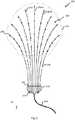
- a schematic illustration of one embodiment of a multi-branch stimulation electrode 200also referred to herein as a multi-branch electrode array, is shown.
- the multi-branch stimulation electrode 200can be used in the place of one or both of leads 106, 108 shown in Figure 1 .
- the multi-branch stimulation electrode 200can advantageously enable treatment of a broader area than treated by use of leads 106, 108.
- the multi-branch stimulation electrode 200can enable peripheral field stimulation (PFS).
- PFSincludes the treatment of an area of pain or an area of referred pain. In some embodiments, this pain is not associated with an identified nerve.
- PFScan include stimulation of a broad area as no specific nerve is identified and targeted.
- the broader area treatment enabled by the multi-branch stimulation electrode 200can ease placement of the multi-branch stimulation electrode 200 with respect to the nerve as the exact placement of the multi-branch stimulation electrode 200 is less important than in the case of leads 106, 108.
- the multi-branch stimulation electrode 200can, in some embodiments, be placed in subcutaneous tissue such as, for example, the layer of subcutaneous adipose tissue located between muscle and the epidermis.
- the multi-branch stimulation electrode 200can include a plurality of branches 202.
- the branches 202can be configured to deliver one or several electric pulses to tissue of the patient.
- the branches 202can comprise a variety of shapes and sizes and can be made from a variety of materials.
- the branches 202comprise a plurality of the elongate members that have a proximal end 204 and a distal end 206.
- Multi-branch stimulation electrode 200can have any desired number of branches including, for example, an even number of branches 202 or an odd number of branches 202.
- the multi-branch stimulation electrodecan have, for example, 2 branches 202, 3 branches 202, 4 branches 202, 5 branches 202, 6 branches 202, 7 branches 202, 8 branches 202, 9 branches 202, 10 branches 202, 11 branches 202, 12 branches 202, 15 branches 202, 20 branches 202, 50 branches 202, and/or any other or intermediate number of branches.
- some of the branches 202can be an anodic branches, and some of the branches 202 can be cathodic branches.
- the branches 202can alternate between anodic and cathodic branches such that the adjacent branches 202 to an anodic branch are cathodic branches and the adjacent branches to a cathodic branch are anodic branches.
- some or all of the branchescan include one or several stimulation contacts that can be anodic stimulation contacts
- some or all of the branchescan include one or several stimulation contacts that can be cathodic stimulation contacts.
- these stimulation contactscan alternate such that an anodic stimulation contact is adjacent to cathodic stimulation contacts, and such that cathodic stimulation contacts are adjacent to anodic stimulation contacts.
- the systemis designed to re-configure one or more of the branches between anodic or cathodic configurations and/or one or more of the stimulation contacts between anodic or cathodic configurations.
- each of the branches 202can be the same size, have the same shape, and be made from the same material, and in some embodiments, some of the branches 202 can have one of a different size, shape, or material than others of the branches 202.
- a first branch 202-Alocated along a central axis of the multi-branch stimulation electrode 200, is longer than a second branch 202-B, located adjacent to the central access of the multi-branch stimulation electrode 200.
- the first branch 202-Aextends parallel to a y-axis such that the distal end 206 is farther in the positive y-direction than the proximal end 204.
- the first branch 202-Aextends perpendicular to the x-axis, and the second branch 202-B is farther in the positive x-direction than the first branch 202-A.
- the multi-branch stimulation electrode 200can be further defined by the z-axis which extends from the intersection of the x-and y-axes according to the right-hand rule.
- the branches 202can be spaced apart from each other.
- the branches 202can be spaced apart from each other such that branches 202 extend parallel to each other, and in some embodiments, the branches can be spaced apart such that the branches 202 are non-parallel to each other.
- the spacing and arrangement of the brancheswill vary depending on whether the electrode array is in a deployed or non-deployed configuration.
- the branches 202can be spaced in a fan or rake-shaped arrangement, wherein the proximal ends 204 of the branches 202 are spaced more closely to each other than are the distal ends 206 of the branches.
- the nonparallel extension of the branches 202can result in changing spacing between the branches.
- the spacing between the branches 202increases when moving in the positive y-direction (towards the top of the page) from the proximal end 204 to the distal end 206 of any of the branches 202.
- some or all of the branches 202can be each located in a single plane along the z-axis (e.g.
- one or several of the branches 202can be located in multiple planes along the z-axis, and/or extend through multiple planes along the z-axis.
- the position of the branches 202 along the z-axiscan serve to match the shape of the multi-branch stimulation electrode 202, for example, a curved body part into which the multi-branch stimulation electrode 202 is being implanted.
- the position of a point on one or several of the branches 202 in the z-axiscan vary as a function of, for example position on the y-axis and/or on the x-axis.
- the shaping of the multi-branch stimulation electrode 202 in the z-axiscan facilitate maintaining the multi-branch stimulation electrode 200 in the subcutaneous tissue.
- the position of a point on one or several of the branches 202 z-axiscan vary as a function of distance in the x-axis from the first branch 202-A.
- the branches 202 of the electrode arrayare in a substantially planar arrangement, although the branches 202 are not entirely located in a single plane.
- Figure 2Awhich shows the electrode array of Figure 2 in a side view
- all of the branches 202curve slightly downwardly towards distal tips of the branches 202, which facilitates maintaining the branches 202 in a subcutaneous layer of tissue during implantation and insertion, as described further below.
- Figure 2Bwhich shows another embodiment of the electrode array of Figure 2 in a side view, some of the branches 202 curve slightly downwardly towards distal tips of the branches 202, which facilitates maintaining the branches 202 in a subcutaneous layer of tissue during implantation and insertion, as described further below.
- the branches 202curve downwardly such that the distal tips are approximately 0.5 mm, 1 mm, 2 mm, 3 mm, 5 mm, 10 mm, 15 mm, and/or any other or intermediate distance below proximal ends of the branches.
- the spacing between the branches 202changes, the spacing between the conductive portions of the branches 202, which may be stimulation contacts or electrode contacts, changes.
- This change in the distance between the conductive portions of the branches 202changes one or several of the electrical properties, which can be, for example, impedance, of the circuit extending from one of the conductive portions of one branch to another conductive portion of another branch.
- differences in electrical properties of circuits extending from different conductive portions of different branches to each otheraffects the ability of the implantable neurostimulation system 100 to provide desired stimulation to a nerve and/or area.
- the multi-branch stimulation electrode 200can include one or several features configured to counteract the effects of differential spacing between conductive portions of different branches such that the electrical properties of these circuits are the same and/or approximately the same.
- the electrical properties of the circuitsare approximately the same when they vary by less than 40%, 30%, 20%, 10%, 5%, 1%, or any other or intermediate percent from each other.
- some or all of the branches 202can include a body 208.
- the body 208can comprise a variety of shapes and sizes and can be made from a variety of materials.
- the body 208can extend the entire length of the branch 202, and in some embodiments, the body can extend a portion of the length of the branch 202.
- the body 208can be approximately cylindrical when the body 208 is positioned to extend in a straight line and body 208 can have a circular cross-section.
- the body 208can be rigid, flexible, and/or elastic. In some embodiments, the properties of the body 208 can facilitate the implantation of the body 208 and decrease problems caused by the implantation of the body 208. In some embodiments, the body 208 can be more easily implanted when it is rigid. In some embodiments, the body 208 is less likely to cause negative side effects when the body 208 is flexible and/or elastic. In some embodiments, the body 208 can be made of a material that is rigid at a first, pre-insertion temperature and flexible at a second, body temperature. In some embodiments, such material can be rigid during the implantation process but can, as the body 208 warms to body temperature, become flexible.
- the bodycan have an "integrated stiffening element.” Properties of some aspects of stiffening elements will be discussed at greater lengths below.
- the body 208can include, for example, a rigid, biodegradable outer coating and a flexible, inner portion. In such an embodiment, the rigid, biodegradable outer coating can biodegrade after the implantation of the body 208 to leave the flexible, inner portion of the body 208.
- the body 208can comprise a flexible member and a stiffening member, which can be, for example, a pre-formed stiffening member, can be inserted into the body 208 to facilitate implantation. In such an embodiment, after the body 208 has been implanted, the stiffening member can be removed.
- the bodies 208 of the branches 202can comprise a biocompatible material.
- the bodies 208 of the branches 202can comprise, for example, a natural material, a man-made material, a polymer, a metal or metal alloy, or the like.
- the material of the body 208can be selected so as to be flexible at a body temperature and to be rigid or semi rigid at room temperature.
- some or all of the branches 202can include one or several stimulation contacts 210 that can be, for example, located at positions along the body 208 of the therewith associated branch 202.
- the one or several stimulation contacts 210can be configured to pass one or several electrical pulses to a portion of the patient's tissue.
- the stimulation contacts 210can comprise a conductive material that can form, for example, a peripheral band around one or several portions of the body 208.
- the stimulation contacts 206can radially extend beyond the outside edge of the body 204 so as not to be flush with the body 204, and in some embodiments, the stimulation contacts 206 can be flush with the body 204.
- the stimulation contacts 210 on a single branch 202can be spaced apart. In some embodiments, each of the stimulation contacts 210 can be equally spaced along the body 208 of the branch 202, and in some embodiments, the stimulation contacts 210 can be unequally spaced and/or unevenly spaced along the body 208 of the branch 202.
- the stimulation contacts 210can comprise a variety of shapes and sizes and can be made from a variety of materials.
- each of the stimulation contacts 210can comprise the same size and/or shape, and in some embodiments, some or all of the stimulation contacts 210 can comprise different sizes and/or shapes.
- the size, shape, and/or material of some or all of the stimulation contacts 210can be selected based on desired effect on one or several electrical properties of the completed circuit including to stimulation contacts 210 and a portion of the patient tissue. In one embodiment, for example, the size of the stimulation contacts 210 can increase as the distance of the stimulation contact 210 from the proximal end 204 of the branch increases.
- the stimulation contacts 210can have similar and/or the same material properties as the material of the body 208.
- the matching and/or pairing of the material properties of the stimulation contacts 210 and the body 208can decrease stresses that may arise in the one or both of the body 208 and the stimulation contacts 210 during implantation of the multi-branch stimulation electrode 200 in the body of a patient.
- the proximal ends 204 of the branches 202connect to hub 212.
- the hub 212can comprise a variety of shapes and sizes and can be made from a variety of materials.
- the hub 212can comprise a biocompatible outer housing and/or can be made up one or several biocompatible materials.
- the housing of the hub 212can comprise an interior housing and/or an exterior housing.
- the interior housing of the hub 212can be rigid and the exterior of the hub 212 can be flexible and/or deformable.
- a flexible and/or deformable exterior housing of the hub 212can decrease irritation that may arise from implanting the hub 212 in the patient's body.
- the branches 202can connect to the hub 212 in many ways.
- the connections of the branches 202 to the hub 212can be within a single plane in the Z axis, and in some embodiments, the connections of the branches 202 to the hub 212 can be in multiple planes in the z-axis.
- the connections of the branches 202 to the hub 212can be spaced along the x-axis and can, for example, be equally spaced along the x-axis.
- the hub 212, including the connection points of the branches 202 to the hub 212can be sealed so as to decrease the likelihood of bacterial growth within and/or associated with the hub 212.
- the hub 212can include one or several anchor features 214 that can be used to secure and/or fix the position of the hub 212 in the patient's body.
- these anchor features 214comprise suture eyelets that can be used in suturing the hub to tissue within the patient's body.
- the hub 212can connect to lead 216, which lead 216 can connect to one of the pulse generators 102, 104.
- Hub 212can include one or several conductors that are electrically connected with one or several of the stimulation contacts 210 of the branches 202. These one or several conductors can be used to conduct electrical pulses from the pulse generator 102, 104 to the stimulation contacts 210.
- the one or several conductorscan be enclosed in an insulative, biocompatible shell.
- the conductors and the biocompatible shellcan be flexible and/or rigid, can comprise a variety of shapes and sizes, and can be made from a variety of materials.
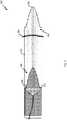
- the implantation system 300can be used to implant the multi-branch stimulation electrode 200 in a patient's body.
- the components of the implantation system 300can comprise a variety of shapes and sizes and can be made from a variety of materials.
- the components of the implantation system 300 and the implantation system 300 as a wholecan be sized and shaped to allow insertion of portions of the implantation system 300 through an incision 302.
- the implantation systemincludes the multi-branch stimulation electrode 200 including, the leads 202, and the hub 212.
- the implantation system 300can include an implantation cartridge 304 that can include an insertion tip 305.
- the insertion tips 305also referred to herein as a piercing tip, can be configured to pierce tissue of the patient.
- the implantation cartridge 304can comprise a variety of shapes and sizes and can be made of a variety of materials.
- the insertion tip 305 of the implantation cartridge 304can extend to a point where a rounded tip and/or can taper to a point or a rounded tip.
- the point or rounded tipcan be inserted into the patient's body through the incision 302 and can ease the insertion of the implantation cartridge 304 through the incision 302.
- the implantation cartridge 304can comprise an elongate member having a U-shaped cross-section with a bottom and sides extending in the same direction from the bottom. This bottom and sides of the implantation cartridge 304 partially bound an internal volume of the implantation cartridge 304. In some embodiments, the other components of the implantation system 300 can be held within and/or retained within the internal volume of the implantation cartridge 304.
- the implantation cartridge 304can be configured to house the multi-branch stimulation electrode 200 and hold the branches 202 of the multi-branch stimulation electrode 200 in a first, insertion position.
- the branches 202which can be, for example, pre-formed branches of the multi-branch stimulation electrode 200 that are held parallel to each other in the first, insertion position.
- the implantation cartridge 304can include features configured to hold the branches 202 of the multi-branch stimulation electrode 200 and the first, insertion position.
- the features configured to hold the branches 202 of multi-branch stimulation electrode 200 in the first, insertion positioncan comprise a comb-shaped guide.
- one or several of the branches 202 of the multi-branch stimulation electrode 200can be held between teeth of the comb-shaped guide.
- the teeth of the comb shaped guidecan extend in the same direction as the sides such that the comb shaped guide and the implantation cartridge 304 can be lifted off of the multi-branch stimulation electrode 200 after implantation of the multi-branch stimulation electrode 200 in the patient's body.
- the implantation system 300can include an insertion sleigh 306.
- the insertion sleighcan fit within the internal volume of the implantation cartridge 304 and can be slidable towards and away from the insertion tip 305 of the implantation cartridge 304.
- the insertion sleigh 304can engage with, for example, some or all of the multi-branch stimulation electrode 200 such as, for example, the hub 212 to allow insertion of and/or implantation of the multi-branch stimulation electrode 200 when the insertion sleigh 304 is moved towards the insertion tip 305 of the implantation cartridge 304.
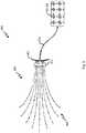
- FIG. 4Aa schematic illustration of one embodiment of a process for the implantation of the multi-branch stimulation electrode 200 is shown.
- the processbegins in Figure 4A , wherein the insertion tip 305 of the insertion cartridge 304 is inserted through the incision 302 in the patient's body.
- the insertion sleigh 306is displaced towards the insertion tip 305 of the insertion cartridge 304.
- the branches 202 of the multi-branch stimulation electrode 200penetrate into the tissue of the patient and move towards a second, implanted position.
- the branches 202 of the multi-branch stimulation electrode 200have a desired spacing and distribution when they reach the second, implanted position.
- Figure 4Bdepicts one embodiment of the implantation system 300 after the branches 202 of the multi-branch stimulation electrode 200 have reached the second, implanted position.
- the branches 202 of the multi-branch stimulation electrode 200have reached the second, implanted position when the insertion sleigh 306 has reached the insertion .305 of the insertion cartridge 304 and when the hub 212 of the multi-branch stimulation electrode is inserted through the incision 302.
- the insertion sleigh 306 and the insertion cartridge 304are separated from the multi-branch stimulation electrode and removed from the patient's body out of the insertion 302 as is depicted in Figure 4C .
- the multi-branch stimulation electrode 200can be secured with respect to the incision 302 and/or with respect to the patient's body.
- the multi-branch stimulation electrode 200can be secured with respect to the patient's body via the anchor features 214 of the hub 212.
- the stiffening elements 308, if the multi-branch stimulation electrode 200 includes stiffening elements 308,can be withdrawn.
- the stiffening elements 308can provide rigidity to the branches 202 of the multi-branch stimulation electrode 200 to allow penetration of the branches 202 into and through tissue of the patient's body, and in some embodiments, the stiffening elements 308 can bias the branches 202 of the multi-branch stimulation electrode 200 towards the second, implanted position. After the branches 202 have reached the desired position, the stiffening elements 308 can be withdrawn from the branches 202 so the branches 202 have a desired level of flexibility.
- the stiffening members 308can be connected to a stiffening element hub 312 and the stiffening members 308 can be withdrawn from the branches 202 of multi-branch stimulation electrode 200 by withdrawing the stiffening element hub 312 from the hub 212 and out of and through the incision 302. In the event that the withdrawal of the stiffening members 308 created one or several voids or cavities within one or both of the hub 212 and the branches 202, the one or several voids or cavities can be sealed, plugged, and/or filled.
- the pulse delivery system 500can include the implanted multi-branch stimulation electrode 200 including, for example, branches 202 in the second, implanted position and hub 212.
- the lead 216 of the multi-branch stimulation electrode 200can be connected to the pulse generator 102, 104.
- the hub 212 and the branches 202 of the multi-branch stimulation electrode 200can be implanted within the patient's body, inserted past the incision 302, and the lead 216 can extend through the incision 302 from inside the patient's body to outside the patient's body.
- the lead 216and can connect to the pulse generator 102, 104 at a point outside the patient's body.
- the lead 216can be entirely implanted within the patient's body and the pulse generator 102, 104 can likewise be entirely implanted within the patient's body.
- the branch 202can include the proximal end 204 connecting to the hub 212 that contacts the stiffening member hub 312, and the distal end 206.
- the distal end 206 of the branch 202can include the insertion member 400.
- the insertion of the 400can comprise a variety of shapes and sizes and can be made from a variety of materials.
- the insertion member 400can be configured to interact with the stiffening member 308 during the implantation of the hub 212 to prevent the stiffening member 308 from penetrating through the branch 202.
- the insertion member 400can comprise a penetration material that can be, for example, metal, hard plastic, a composite, and/or any other material capable of interacting with the stiffening member 308 during the implantation and not allowing the stiffening member to penetrate the branch 202.
- the insertion member 400can be further configured to facilitate implantation.
- the insertion member 400can be shaped to facilitate the insertion and can include, for example, a pointed tip.
- the branch 202 depicted in Figure 6further includes an elastic zone 402 and an inelastic zone 404.
- the elastic zone 402can be a portion of the branch 202 that has elastic properties and therefore allows a dimension of the branch 202 to temporarily change in response to the application of a force.
- the elastic zone 402can be located at any position on and/or along the insertion member 202 and the elastic zone 402 can have any desired size and shape.
- the entire branch 202can be the elastic zone 402, and in some embodiments, the branch 202 can include an inelastic zone 404.
- the inelastic zonecan be a portion of the branch 202 that is not intended to have elastic properties and/or that does not have elastic properties at the load levels applied during the implantation of the multi-branch stimulation electrode 200.
- the elastic zone 402can be located proximate to the proximal end 204 of the branch 202 and the inelastic zone 404 can be located proximate to the distal end 206 of the branch 202.
- the stimulation contacts 210can be located in the inelastic zone 404.
- placement of the stimulation contacts 210 in the inelastic zonecan decrease stresses created in one or both of the stimulation contacts 210 and the branch 202 during the implantation of the multi-branch stimulation electrode 200 by eliminating and/or decreasing discrepancies between the material properties of the stimulation contacts 210 and the branch 202.
- FIG. 7A-7Csection views of some embodiments of the branch 202 are shown.
- FIG. 7Asection view of one embodiment of branch 202 is shown.
- the branch 202is connected at its proximal end 204 to hub 212, which hub is connected to lead 216 and contacts stiffening element hub 312.
- the branch 202further includes a penetrating element 400 located at the distal end 200.
- the branch 202can include one or several branch walls 406 that can define an internal channel 408 of the branch 202.
- the internal channel 408can comprise a single channel that can be, for example, configured to receive a stiffening element 308, and in some embodiments, the internal channel 408 can comprise a channel configured to receive the stiffening element 308 and a channel configured to receive one or several conductors configured to connect the stimulation contacts 210 to the lead 216.
- the one or several conductorscan be incorporated into the branch walls 406 of the branch 202, and in some embodiments, the one or several conductors can be loosely contained within the internal channel 408.
- the branch 202includes a single internal channel 408 configured to receive both the stiffening element 308, a main wire 410, and a plurality of branch wires 412.
- the main wire 410can carry electrical pulses from the lead 216 to the stimulation contacts 210.
- the main wirecan connect to the lead 216 in the hub 212 and can be electrically connected to the stimulation contacts 210 via one or several branch wires 412.
- the branch wirescan include one or several electrical components configured to carry electrical property of the circuit with which the stimulation contact 210 connected to the branch wire 412 is associated.
- these electrical componentscan include one or several resistors, capacitors, or the like.
- the stiffening element 308can extend from the stiffening element hub 312 to contact the insertion tip 400. In some embodiments, as slight differences in the length of one or several of the branches 202 and/or of the stiffening elements 308 may arise, the stiffening elements 308 may not adequately stiffen one or several of the branches 202 to allow implantation of the branches 202.
- one of the stiffening elements 308may be relatively longer than others of the stiffening elements 308 with respect to one or several branches. As such, the relatively longer of the stiffening elements 308 may contact the insertion tip 408 of one of the branches 202 and others of the stiffening elements 308 may not contact the insertion tip 408 of the others of the branches 202.
- the multi-branch stimulation electrode 200can include one or several features to overcome these problems to thereby facilitate implantation of multi-branch stimulation electrode 200.
- these featurescan include one or several elastic portions of the branches 202.
- these featurescan include one or several features located in the stiffening element 308 and/or in the stiffening element hub 312 that can allow a change to the length of the stiffening element and/or similar features in the hub 212 which can allow changes in the length of the branches 202.
- such featurescan allow for improved implantation of the multi-branch stimulation electrode 200.
- the branch 202includes features configured to facilitate in creating the same and/or similar electrical properties at circuits arising when the branches 202 of the multi-branch stimulation electrode 200 are not parallel spaced, and features configured to allow the branch 202 to stretch so as to compensate for discrepancies in the length of some or all of the branches 202 and/or the stiffening elements 308.
- the branch 202includes extending wire 414 and returning wire 416.
- the extending wireextends from the hub 212 towards the distal end 206 of the branch 202 wherein the direction of the extension of the wire changes and the returning wire 414 returns towards the hub 212. In some embodiments, this can reverse the order with which the stimulation contacts 210 are connected to the wire which can thereby result in the greatest amount of resistance being experienced at the stimulation contact 210 relatively closest to the hub 212. In some embodiments, this looping of the wire can further provide access wire within the branch 202 such that the wire does not break or stretch if the branch 202 elastically deforms during implantation of the multi-branch stimulation electrode 200.
- the branch 202includes features configured to allow the branch 202 to stretch so as to compensate for discrepancies in the length of some or all of the branches 202 and/or the stiffening elements 308.
- the main wire 410includes a plurality of extension coils 418 located in the internal channel 408 of the branch 202.
- these extension coils 418can allow the overall length of the main wire 410 to change with changes in the length of the branch 202.
- thiscan allow for the elastic deformation of the branch 202 without stretching and/or breaking the main wire 410.
- the extension coilscan comprise a variety of shapes and sizes and can include, for example, any desired number of loops or coils.
- the extension coils 418can be designed according to expected changes in the length of the branch 202.
Landscapes
- Health & Medical Sciences (AREA)
- Public Health (AREA)
- Engineering & Computer Science (AREA)
- Nuclear Medicine, Radiotherapy & Molecular Imaging (AREA)
- Radiology & Medical Imaging (AREA)
- Life Sciences & Earth Sciences (AREA)
- Animal Behavior & Ethology (AREA)
- Biomedical Technology (AREA)
- Veterinary Medicine (AREA)
- General Health & Medical Sciences (AREA)
- Cardiology (AREA)
- Heart & Thoracic Surgery (AREA)
- Neurology (AREA)
- Neurosurgery (AREA)
- Orthopedic Medicine & Surgery (AREA)
- Electrotherapy Devices (AREA)
Description
- The prevalence of use of medical devices in treating ailments is increasing with time. In many instances, and as these medical devices are made smaller, these medical devices are frequently implanted within a patient. While the desirability of implantable devices is increasing as the size of the devices has decreased, the implantation process still frequently requires complicated surgery which can expose the patient to significant risks and protracted recovery times. In light of this, further methods, systems, and devices are desired to increase the ease of implantation of medical devices.
US2002/0116042 describes a furcated medical electrical lead for neurological applications.US6427086 describes a means and method for placing an implantable neurostimulation control module into a place in the cranium.US2003/078633 describes electrical therapy by delivering electrical pulses through at least one subcutaneously implanted electrode.US2008/132961 describes a stimulation system that includes an implantable micro stimulator.US2012/130465 describes a vestibular stimulation array having one or more separate electrode arrays each operatively adapted for implantation in a semicircular canal of the vestibular system. - The invention is defined in claim 1. Further aspects and preferred embodiments are defined in the appended claims. Aspects, embodiments and examples of the present disclosure which do not fall under the scope of the appended claims do not form part of the invention and are merely provided for illustrative purposes. One aspect of the present disclosure relates to a neurostimulation system. The neurostimulation system includes an implantable pulse generator that can generate one or more non-ablative neurostimulation electrical signals, and a multi-branch electrode array that can be coupled to the pulse generator to thereby transmit the one or more non-ablative neurostimulation electrical signals to a nerve tissue. The multi-branch electrode array can include a plurality of branches. In some embodiments, at least some of the branches each include a plurality of electrode contacts. In some embodiments, when in a deployed configuration, the plurality of branches diverge away from one another such that distal tips of the branches are spaced farther apart than proximate portions of the branches. In some embodiments, when in the deployed configuration, the plurality of branches are in a substantially planar arrangement.
- In some embodiment of the neurostimulation system, the plurality of branches are in a rake-shaped arrangement when in the deployed configuration. In some embodiments, the substantially planar arrangement comprises an arrangement in which the branches branch out across and curve downwardly from a reference plane. In some embodiments, the downward curve of the branches facilitates maintaining the branches in a subcutaneous tissue layer during deployment of the electrode array. In some embodiments, at least some of the branches include blunt dissecting distal tips.
- In some embodiment of the neurostimulation system, the non-ablative neurostimulation electrical signals have a pulse amplitude of 0 - 1,000 mA. In some embodiments, the electrode array further can include a hub that can include features to allow anchoring of the hub to a tissue. In some embodiments, at least some of the electrode contacts are anode electrode contacts and wherein at least some of the electrode contacts are cathode electrode contacts. In some embodiments, of the electrodes on one branch are anode electrode contacts and all of the electrodes on an adjacent branch are cathode electrode contacts.
- In some embodiment of the neurostimulation system, at least some of the branches include stiffening components that increase the stiffness of the branches to facilitate blunt dissecting by the branches. In some embodiments, the stiffening components can be a plurality of elongate members that can be connected by a stiffening element hub. In some embodiments, at least some of the branches can receive the stiffening elements.
- In some embodiment of the neurostimulation system, the size of the electrode contacts varies as a function of position on at least some of the branches. The branches have a proximal end and a distal end. In some embodiments, the size of the electrode contact increases when the distance from the proximal end increases, or in other words, when the proximity of the electrode contact to the distal end of the branch increases. In some embodiments, some of the electrode contacts are each electrically connected to a resistive element. In some embodiments, the resistance of the resistive element increases when the proximity of the electrode contact to the proximal end of the branch increases.
- One aspect of the present disclosure relates to an implantable electrode array system. The implantable electrode array system includes a multi-branch electrode array including a plurality of elongated branches that each include at least one electrode contact and a blunt dissecting distal tip, and an implantation cartridge for deploying the multi-branch electrode array from a retracted configuration to a deployed configuration. In some embodiments, the branches are retracted relative to the implantation cartridge when in the retracted configuration, and, wherein, the branches extend outwardly from the implantation cartridge a further distance than in the retracted configuration when in the deployed configuration. In some embodiments, the branches are arranged in a substantially planar fan-shaped arrangement when in the deployed configuration.
- In some embodiments, at least some of the branches include stiffening components that increase the stiffness of the branches to facilitate blunt dissecting by the branches. In some embodiments, the stiffening components can include a plurality of elongate members that are connected by a stiffening element hub. In some embodiments, at least some of the branches can receive the stiffening elements. In some embodiments, the stiffening element can be a biodegradable outer layer on at least some of the branches. In some embodiment, at least some of the branches include an integrated stiffening element.
- One aspect of the present disclosure relates to an implantable electrode array. The implantable electrode array includes a multi-branch electrode array including a plurality of elongated branches that each include at least one electrode contact and a blunt dissecting distal tip. In some embodiments, the branches are arranged in a substantially planar fan-shaped arrangement when in the deployed configuration.
- In some embodiments, at least some of the branches include stiffening components that increase the stiffness of the branches to facilitate blunt dissecting by the branches. In some embodiments, the stiffening components can be a plurality of elongate members that are connected by a stiffening element hub. In some embodiments, at least some of the branches can receive the stiffening elements. In some embodiments, the stiffening element can be a biodegradable outer layer on at least some of the branches. In some embodiments, at least some of the branches include an integrated stiffening element.
- Further areas of applicability of the present disclosure will become apparent from the detailed description provided hereinafter. It should be understood that the detailed description and specific examples, while indicating various embodiments, are intended for purposes of illustration only and are not intended to necessarily limit the scope of the disclosure.
Figure 1 is a schematic illustration of one embodiment of an implantable neurostimulation system.Figure 2 is a top view of one embodiment of a multi-branch stimulation electrode.Figures 2A and 2B are side views of embodiments of the multi-branch stimulation electrode shown inFigure 2 .Figure 3 is a top view of one embodiment of an implantation system including the multi-branch stimulation electrode.Figures 4A-4C depict one embodiment of a process for implanting a multi-branch stimulation electrode.Figure 5 is a schematic illustration of one embodiment of a pulse delivery system.Figure 6 is a side view of one embodiment of a branch of a multi-branch stimulation electrode.Figures 7A-7C are section views of embodiment of branches of a multi-branch stimulation electrode.- In the appended figures, similar components and/or features may have the same reference label. Where the reference label is used in the specification, the description is applicable to any one of the similar components having the same reference label.
- A significant percentage of the Western (EU and US) population is affected by Neuropathic pain (chronic intractable pain due to nerve damage). In many people, this pain is severe. There are thousands of patients that have chronic intractable pain involving a nerve. Neuropathic pain can be very difficult to treat with only half of patients achieving partial relief. Thus, determining the best treatment for individual patients remains challenging. Conventional treatments include certain antidepressants, anti-epileptic drugs and opioids. However, side effects from these drugs can be detrimental. In some of these cases, electrical stimulation, including FES, can provide effect treatment of this pain without the drug-related side effects.
- A spinal cord stimulator is a device used to deliver pulsed electrical signals to the spinal cord to control chronic pain. Because electrical stimulation is a purely electrical treatment and does not cause side effects similar to those caused by drugs, an increasing number of physicians and patients favor the use of electrical stimulation over drugs as a treatment for pain. The exact mechanisms of pain relief by spinal cord stimulation (SCS) are unknown. Early SCS trials were based the Gate Control Theory, which posits that pain is transmitted by two kinds of afferent nerve fibers. One is the larger myelinated Aδ fiber, which carries quick, intense-pain messages. The other is the smaller, unmyelinated "C" fiber, which transmits throbbing, chronic pain messages. A third type of nerve fiber, called Aβ, is "non-nociceptive," meaning it does not transmit pain stimuli. The gate control theory asserts that signals transmitted by the Aδ and C pain fibers can be thwarted by the activation/stimulation of the non-nociceptive Aβ fibers and thus inhibit an individual's perception of pain. Thus, neurostimulation provides pain relief by blocking the pain messages before they reach the brain.
- SCS is often used in the treatment of failed back surgery syndrome, a chronic pain syndrome that has refractory pain due to ischemia. SCS complications have been reported in a large portion, possibly 30% to 40%, of all SCS patients. This increases the overall costs of patient pain management and decreases the efficacy of SCS. Common complications include: infection, hemorrhaging, injury of nerve tissue, placing device into the wrong compartment, hardware malfunction, lead migration, lead breakage, lead disconnection, lead erosion, pain at the implant site, generator overheating, and charger overheating. The occurrence rates of common complications are surprisingly high: including lead extension connection issues, lead breakage, lead migration and infection.
- Peripheral neuropathy, another condition that can be treated with electrical stimulation, may be either inherited or acquired. Causes of acquired peripheral neuropathy include physical injury (trauma) to a nerve, viruses, tumors, toxins, autoimmune responses, nutritional deficiencies, alcoholism, diabetes, and vascular and metabolic disorders. Acquired peripheral neuropathies are grouped into three broad categories: those caused by systemic disease, those caused by trauma, and those caused by infections or autoimmune disorders affecting nerve tissue. One example of an acquired peripheral neuropathy is trigeminal neuralgia, in which damage to the trigeminal nerve (the large nerve of the head and face) causes episodic attacks of excruciating, lightning-like pain on one side of the face.
- A high percentage of patients with peripheral neuropathic pain do not benefit from SCS for various reasons. However, many of these patients can receive acceptable levels of pain relief via direct electrical stimulation to the corresponding peripheral nerves. This therapy is called peripheral nerve stimulation (PNS). As FDA approved PNS devices have not been commercially available in the US market, Standard spinal cord stimulator (SCS) devices are often used off label by pain physicians to treat this condition. A significant portion of SCS devices that have been sold may have been used off-label for PNS.
- As current commercially-available SCS systems were designed for stimulating the spinal cord and not for peripheral nerve stimulation, there are more device complications associated with the use of SCS systems for PNS than for SCS. Current SCS devices (generators) are large and bulky. In the event that an SCS is used for PNS, the SCS generator is typically implanted in the abdominal or in the lower back above the buttocks and long leads are tunneled across multiple joints to reach the target peripheral nerves in the arms, legs or face. The excessive tunneling and the crossing of joints leads to increased post-surgical pain and higher device failure rates. Additionally, rigid leads can lead to skin erosion and penetration, with lead failure rates being far too high within the first few years of implantation. Many or even most complications result in replacement surgery and even multiple replacement surgeries in some cases.
- One embodiment of an
implantable neurostimulation system 100 is shown inFigure 1 , whichimplantable neurostimulation system 100 can be, for example, a peripherally-implantable neurostimulation system 100. In some embodiments, theimplantable neurostimulation system 100 can be used in treating patients with, for example, chronic, severe, refractory neuropathic pain originating from peripheral nerves. In some embodiments, theimplantable neurostimulation system 100 can be used to either stimulate a target peripheral nerve or the posterior epidural space of the spine. - The
implantable neurostimulation system 100 can include one or several pulse generators. The pulse generators can comprise a variety of shapes and sizes, and can be made from a variety of materials. In some embodiments, the one or several pulse generators can generate one or several non-ablative electrical pulses that are delivered to a nerve to control pain. In some embodiments, these pulses can have a pulse amplitude of between 0-1,000 mA, 0-100 mA, 0-50 mA, 0-25 mA, and/or any other or intermediate range of amplitudes. One or more of the pulse generators can include a processor and/or memory. In some embodiments, the processor can provide instructions to and receive information from the other components of theimplantable neurostimulation system 100. The processor can act according to stored instructions, which stored instructions can be located in memory, associated with the processor, and/or in other components of thecontent injection system 100. The processor can, in accordance with stored instructions, make decisions. The processor can comprise a microprocessor, such as a microprocessor from Intel® or Advanced Micro Devices, Inc.®, or the like. - In some embodiments, the stored instructions directing the operation of the processor may be implemented by hardware, software, scripting languages, firmware, middleware, microcode, hardware description languages, and/or any combination thereof. When implemented in software, firmware, middleware, scripting language, and/or microcode, the program code or code segments to perform the necessary tasks may be stored in a machine readable medium such as a storage medium. A code segment or machine-executable instruction may represent a procedure, a function, a subprogram, a program, a routine, a subroutine, a module, a software package, a script, a class, or any combination of instructions, data structures, and/or program statements. A code segment may be coupled to another code segment or a hardware circuit by passing and/or receiving information, data, arguments, parameters, and/or memory contents. Information, arguments, parameters, data, etc. may be passed, forwarded, or transmitted via any suitable means including memory sharing, message passing, token passing, network transmission, etc.
- In some embodiments, the memory of one or both of the pulse generators can be the storage medium containing the stored instructions. The memory may represent one or more memories for storing data, including read only memory (ROM), random access memory (RAM), magnetic RAM, core memory, magnetic disk storage mediums, optical storage mediums, flash memory devices and/or other machine readable mediums for storing information. In some embodiments, the memory may be implemented within the processor or external to the processor. In some embodiments, the memory can be any type of long term, short term, volatile, nonvolatile, or other storage medium and is not to be limited to any particular type of memory or number of memories, or type of media upon which memory is stored. In some embodiments, the memory can include, for example, one or both of volatile and nonvolatile memory. In one specific embodiment, the memory can include a volatile portion such as RAM memory, and a nonvolatile portion such as flash memory.
- In some embodiments, one of the pulse generators can be an
external pulse generator 102 or animplantable pulse generator 104. Theexternal pulse generator 102 can be used to evaluate the suitability of a patient for treatment with theimplantable neurostimulation system 100 and/or for implantation of animplantable pulse generator 104. - In some embodiments, one of the pulse generators can be the
implantable pulse generator 104, which can be sized and shaped, and made of material to allow implantation of theimplantable pulse generator 104 inside of a body. In some embodiments, theimplantable pulse generator 104 can be sized and shaped so as to allow placement of theimplantable pulse generator 104 at any desired location in a body, and in some embodiments, placed proximate to a peripheral nerve such that leads (discussed below) are not tunneled across joints and/or such that extension cables are not needed. - In some embodiments, the electrical pulses generated by the pulse generator can be delivered to one or
several nerves 110 and/or to tissue proximate to one orseveral nerves 110 via one or several leads. The leads can include conductive portions, such as electrodes or contact portions of electrodes, and non-conductive portions. The leads can have a variety of shapes, can be in a variety of sizes, and can be made from a variety of materials, which size, shape, and materials can be dictated by the application or other factors. - In some embodiments, the leads can include an
anodic lead 106 and/or acathodic lead 108. In some embodiments, theanodic lead 106 and thecathodic lead 108 can be identical leads, but can receive pulses of different polarity from the pulse generator. - In some embodiments, the leads can connect directly to the pulse generator, and in some embodiments, the leads can be connected to the pulse generator via a
connector 112 and aconnector cable 114. Theconnector 112 can comprise any device that is able to electrically connect the leads to theconnector cable 114. Likewise, the connector cable can be any device capable of transmitting distinct electrical pulses to theanodic lead 106 and thecathodic lead 108. - In some embodiments, the
implantable neurostimulation system 100 can include acharger 116 that can be configured to recharge theimplantable pulse generator 104 when theimplantable pulse generator 104 is implanted within a body. Thecharger 116 can comprise a variety of shapes, sizes, and features, and can be made from a variety of materials. Like thepulse generators charger 116 can include a processor and/or memory having similar characteristics to those discussed above. In some embodiments, thecharger 116 can recharge theimplantable pulse generator 104 via an inductive coupling. - In some embodiments, one or several properties of the electrical pulses can be controlled via a controller. In some embodiments, these properties can include, for example, the frequency, strength, pattern, duration, or other aspects of the timing and magnitude of the electrical pulses. In one embodiment, these properties can include, for example, a voltage, a current, or the like. In one embodiment, a first electrical pulse can have a first property and a second electrical pulse can have a second property. This control of the electrical pulses can include the creation of one or several electrical pulse programs, plans, or patterns, and in some embodiments, this can include the selection of one or several pre-existing electrical pulse programs, plans, or patterns. In the embodiment depicted in
Figure 1 , theimplantable neurostimulation system 100 includes a controller that is aclinician programmer 118. Theclinician programmer 118 can be used to create one or several pulse programs, plans, or patterns and/or to select one or several of the created pulse programs, plans, or patterns. In some embodiments, theclinician programmer 118 can be used to program the operation of the pulse generators including, for example, one or both of theexternal pulse generator 102 and theimplantable pulse generator 104. Theclinician programmer 118 can comprise a computing device that can wiredly and/or wirelessly communicate with the pulse generators. In some embodiments, theclinician programmer 118 can be further configured to receive information from the pulse generators indicative of the operation and/or effectiveness of the pulse generators and the leads. - In some embodiments, the controller of the
implantable neurostimulation system 100 can include apatient remote 120. The patient remote 120 can comprise a computing device that can communicate with the pulse generators via a wired or wireless connection. The patient remote 120 can be used to program the pulse generator, and in some embodiments, the patient remote 120 can include one or several pulse generation programs, plans, or patterns created by theclinician programmer 118. In some embodiments, the patient remote 120 can be used to select one or several of the pre-existing pulse generation programs, plans, or patterns and to select, for example, the duration of the selected one of the one or several pulse generation programs, plans, or patterns. - Advantageously, the above outlined components of the
implantable neurostimulation system 100 can be used to control and provide the generation of electrical pulses to mitigate patient pain. - With reference now to
Figure 2 , a schematic illustration of one embodiment of amulti-branch stimulation electrode 200, also referred to herein as a multi-branch electrode array, is shown. In some embodiments, themulti-branch stimulation electrode 200 can be used in the place of one or both ofleads Figure 1 . In some embodiments, themulti-branch stimulation electrode 200 can advantageously enable treatment of a broader area than treated by use ofleads multi-branch stimulation electrode 200 can enable peripheral field stimulation (PFS). In some embodiments, PFS includes the treatment of an area of pain or an area of referred pain. In some embodiments, this pain is not associated with an identified nerve. In contrast to PNS in which a specific nerve is identified and targeted, PFS can include stimulation of a broad area as no specific nerve is identified and targeted. - In one embodiment, for example, the broader area treatment enabled by the
multi-branch stimulation electrode 200 can ease placement of themulti-branch stimulation electrode 200 with respect to the nerve as the exact placement of themulti-branch stimulation electrode 200 is less important than in the case ofleads multi-branch stimulation electrode 200 can, in some embodiments, be placed in subcutaneous tissue such as, for example, the layer of subcutaneous adipose tissue located between muscle and the epidermis. - The
multi-branch stimulation electrode 200 can include a plurality ofbranches 202. In some embodiments, thebranches 202 can be configured to deliver one or several electric pulses to tissue of the patient. In some embodiments, thebranches 202 can comprise a variety of shapes and sizes and can be made from a variety of materials. In the embodiment depicted inFigure 2 , thebranches 202 comprise a plurality of the elongate members that have aproximal end 204 and adistal end 206. Multi-branch stimulation electrode 200 can have any desired number of branches including, for example, an even number ofbranches 202 or an odd number ofbranches 202. In some embodiments, the multi-branch stimulation electrode can have, for example, 2branches 202, 3branches branches 202, 5branches 202, 6branches 202, 7branches 202, 8branches 202, 9branches 202, 10branches 202, 11branches 202, 12branches 202, 15branches 202, 20branches 202, 50branches 202, and/or any other or intermediate number of branches. In some embodiments, some of thebranches 202 can be an anodic branches, and some of thebranches 202 can be cathodic branches. In some embodiments, thebranches 202 can alternate between anodic and cathodic branches such that theadjacent branches 202 to an anodic branch are cathodic branches and the adjacent branches to a cathodic branch are anodic branches. Alternatively, in some embodiments, some or all of the branches can include one or several stimulation contacts that can be anodic stimulation contacts, and some or all of the branches can include one or several stimulation contacts that can be cathodic stimulation contacts. In some embodiments, these stimulation contacts can alternate such that an anodic stimulation contact is adjacent to cathodic stimulation contacts, and such that cathodic stimulation contacts are adjacent to anodic stimulation contacts. Advantageously, by alternating between an anodic and a cathodic branch, and/or alternating between anodic and cathodic stimulation contacts, the creation of circuits through the patient's tissue to allow transmission of electric pulses can be facilitated. In some instances, the system is designed to re-configure one or more of the branches between anodic or cathodic configurations and/or one or more of the stimulation contacts between anodic or cathodic configurations.- In some embodiments, each of the
branches 202 can be the same size, have the same shape, and be made from the same material, and in some embodiments, some of thebranches 202 can have one of a different size, shape, or material than others of thebranches 202. For example, in the embodiment depicted inFigure 2 , a first branch 202-A, located along a central axis of themulti-branch stimulation electrode 200, is longer than a second branch 202-B, located adjacent to the central access of themulti-branch stimulation electrode 200. In the embodiment depicted inFigure 2 , the first branch 202-A extends parallel to a y-axis such that thedistal end 206 is farther in the positive y-direction than theproximal end 204. As further seen inFigure 2 , the first branch 202-A extends perpendicular to the x-axis, and the second branch 202-B is farther in the positive x-direction than the first branch 202-A. Although not shown, themulti-branch stimulation electrode 200 can be further defined by the z-axis which extends from the intersection of the x-and y-axes according to the right-hand rule. - In the embodiment depicted in
Figure 2 , thebranches 202 can be spaced apart from each other. In some embodiments, thebranches 202 can be spaced apart from each other such thatbranches 202 extend parallel to each other, and in some embodiments, the branches can be spaced apart such that thebranches 202 are non-parallel to each other. As described further below, in some instances, the spacing and arrangement of the branches will vary depending on whether the electrode array is in a deployed or non-deployed configuration. In some embodiments, thebranches 202 can be spaced in a fan or rake-shaped arrangement, wherein the proximal ends 204 of thebranches 202 are spaced more closely to each other than are the distal ends 206 of the branches. In some embodiments, the nonparallel extension of the branches 202 (when in a deployed configuration) can result in changing spacing between the branches. Specifically, in the embodiment depicted inFigure 2 , the spacing between thebranches 202 increases when moving in the positive y-direction (towards the top of the page) from theproximal end 204 to thedistal end 206 of any of thebranches 202. In some embodiments, some or all of thebranches 202 can be each located in a single plane along the z-axis (e.g. in a plane defined by or parallel to the page offigure 2 ) and in some embodiments, one or several of thebranches 202 can be located in multiple planes along the z-axis, and/or extend through multiple planes along the z-axis. In some embodiments, the position of thebranches 202 along the z-axis can serve to match the shape of themulti-branch stimulation electrode 202, for example, a curved body part into which themulti-branch stimulation electrode 202 is being implanted. In one embodiment in which themulti-branch stimulation electrode 202 is configured for being implanted in, for example, a limb, the position of a point on one or several of thebranches 202 in the z-axis can vary as a function of, for example position on the y-axis and/or on the x-axis. In some embodiments, the shaping of themulti-branch stimulation electrode 202 in the z-axis can facilitate maintaining themulti-branch stimulation electrode 200 in the subcutaneous tissue. In one embodiment, for example, the position of a point on one or several of the branches 202 z-axis can vary as a function of distance in the x-axis from the first branch 202-A. - In the particular embodiment of
Figure 2 , thebranches 202 of the electrode array are in a substantially planar arrangement, although thebranches 202 are not entirely located in a single plane. As shown inFigure 2A , which shows the electrode array ofFigure 2 in a side view, all of thebranches 202 curve slightly downwardly towards distal tips of thebranches 202, which facilitates maintaining thebranches 202 in a subcutaneous layer of tissue during implantation and insertion, as described further below. As shown in inFigure 2B , which shows another embodiment of the electrode array ofFigure 2 in a side view, some of thebranches 202 curve slightly downwardly towards distal tips of thebranches 202, which facilitates maintaining thebranches 202 in a subcutaneous layer of tissue during implantation and insertion, as described further below. In some embodiments, thebranches 202 curve downwardly such that the distal tips are approximately 0.5 mm, 1 mm, 2 mm, 3 mm, 5 mm, 10 mm, 15 mm, and/or any other or intermediate distance below proximal ends of the branches. - As the spacing between the
branches 202 changes, the spacing between the conductive portions of thebranches 202, which may be stimulation contacts or electrode contacts, changes. This change in the distance between the conductive portions of thebranches 202 changes one or several of the electrical properties, which can be, for example, impedance, of the circuit extending from one of the conductive portions of one branch to another conductive portion of another branch. In some embodiments, differences in electrical properties of circuits extending from different conductive portions of different branches to each other affects the ability of theimplantable neurostimulation system 100 to provide desired stimulation to a nerve and/or area. - In some embodiments, for example, in which the electrical property is an impedance, different impedances for different circuits can result in more current passing through some circuits and less current passing through others. This can disadvantageously result in unequal stimulation across an area and of a nerve which can inhibit the ability of the
implantable neurostimulation system 100 to treat pain and/or to stimulate a nerve. In some embodiments, themulti-branch stimulation electrode 200 can include one or several features configured to counteract the effects of differential spacing between conductive portions of different branches such that the electrical properties of these circuits are the same and/or approximately the same. In some embodiments, the electrical properties of the circuits are approximately the same when they vary by less than 40%, 30%, 20%, 10%, 5%, 1%, or any other or intermediate percent from each other. - In some embodiments, some or all of the
branches 202 can include abody 208. Thebody 208 can comprise a variety of shapes and sizes and can be made from a variety of materials. In some embodiments, thebody 208 can extend the entire length of thebranch 202, and in some embodiments, the body can extend a portion of the length of thebranch 202. In some embodiments, thebody 208 can be approximately cylindrical when thebody 208 is positioned to extend in a straight line andbody 208 can have a circular cross-section. - In some embodiments, the
body 208 can be rigid, flexible, and/or elastic. In some embodiments, the properties of thebody 208 can facilitate the implantation of thebody 208 and decrease problems caused by the implantation of thebody 208. In some embodiments, thebody 208 can be more easily implanted when it is rigid. In some embodiments, thebody 208 is less likely to cause negative side effects when thebody 208 is flexible and/or elastic. In some embodiments, thebody 208 can be made of a material that is rigid at a first, pre-insertion temperature and flexible at a second, body temperature. In some embodiments, such material can be rigid during the implantation process but can, as thebody 208 warms to body temperature, become flexible. In such an embodiment, the body can have an "integrated stiffening element." Properties of some aspects of stiffening elements will be discussed at greater lengths below. In some embodiments, thebody 208 can include, for example, a rigid, biodegradable outer coating and a flexible, inner portion. In such an embodiment, the rigid, biodegradable outer coating can biodegrade after the implantation of thebody 208 to leave the flexible, inner portion of thebody 208. In some embodiments, thebody 208 can comprise a flexible member and a stiffening member, which can be, for example, a pre-formed stiffening member, can be inserted into thebody 208 to facilitate implantation. In such an embodiment, after thebody 208 has been implanted, the stiffening member can be removed. - In some embodiments, the
bodies 208 of thebranches 202 can comprise a biocompatible material. In some embodiments, thebodies 208 of thebranches 202 can comprise, for example, a natural material, a man-made material, a polymer, a metal or metal alloy, or the like. In some embodiments, the material of thebody 208 can be selected so as to be flexible at a body temperature and to be rigid or semi rigid at room temperature. - In some embodiments, some or all of the
branches 202 can include one orseveral stimulation contacts 210 that can be, for example, located at positions along thebody 208 of the therewith associatedbranch 202. The one orseveral stimulation contacts 210 can be configured to pass one or several electrical pulses to a portion of the patient's tissue. In some embodiments, thestimulation contacts 210 can comprise a conductive material that can form, for example, a peripheral band around one or several portions of thebody 208. In some embodiments, thestimulation contacts 206 can radially extend beyond the outside edge of thebody 204 so as not to be flush with thebody 204, and in some embodiments, thestimulation contacts 206 can be flush with thebody 204. - The
stimulation contacts 210 on asingle branch 202 can be spaced apart. In some embodiments, each of thestimulation contacts 210 can be equally spaced along thebody 208 of thebranch 202, and in some embodiments, thestimulation contacts 210 can be unequally spaced and/or unevenly spaced along thebody 208 of thebranch 202. - The
stimulation contacts 210 can comprise a variety of shapes and sizes and can be made from a variety of materials. In some embodiments, each of thestimulation contacts 210 can comprise the same size and/or shape, and in some embodiments, some or all of thestimulation contacts 210 can comprise different sizes and/or shapes. In some embodiments, the size, shape, and/or material of some or all of thestimulation contacts 210 can be selected based on desired effect on one or several electrical properties of the completed circuit including tostimulation contacts 210 and a portion of the patient tissue. In one embodiment, for example, the size of thestimulation contacts 210 can increase as the distance of thestimulation contact 210 from theproximal end 204 of the branch increases. - In some embodiments, the
stimulation contacts 210 can have similar and/or the same material properties as the material of thebody 208. Advantageously the matching and/or pairing of the material properties of thestimulation contacts 210 and thebody 208 can decrease stresses that may arise in the one or both of thebody 208 and thestimulation contacts 210 during implantation of themulti-branch stimulation electrode 200 in the body of a patient. - In some embodiments, and as seen in
Figure 2 , the proximal ends 204 of thebranches 202 connect tohub 212. Thehub 212 can comprise a variety of shapes and sizes and can be made from a variety of materials. In some embodiments, thehub 212 can comprise a biocompatible outer housing and/or can be made up one or several biocompatible materials. In some embodiments, the housing of thehub 212 can comprise an interior housing and/or an exterior housing. In some embodiments, the interior housing of thehub 212 can be rigid and the exterior of thehub 212 can be flexible and/or deformable. Advantageously, a flexible and/or deformable exterior housing of thehub 212 can decrease irritation that may arise from implanting thehub 212 in the patient's body. - The
branches 202 can connect to thehub 212 in many ways. In some embodiments, the connections of thebranches 202 to thehub 212 can be within a single plane in the Z axis, and in some embodiments, the connections of thebranches 202 to thehub 212 can be in multiple planes in the z-axis. In some embodiments, the connections of thebranches 202 to thehub 212 can be spaced along the x-axis and can, for example, be equally spaced along the x-axis. In some embodiments, thehub 212, including the connection points of thebranches 202 to thehub 212, can be sealed so as to decrease the likelihood of bacterial growth within and/or associated with thehub 212. - The
hub 212 can include one or several anchor features 214 that can be used to secure and/or fix the position of thehub 212 in the patient's body. In the embodiment depicted inFigure 2 , these anchor features 214 comprise suture eyelets that can be used in suturing the hub to tissue within the patient's body. - The
hub 212 can connect to lead 216, which lead 216 can connect to one of thepulse generators Hub 212 can include one or several conductors that are electrically connected with one or several of thestimulation contacts 210 of thebranches 202. These one or several conductors can be used to conduct electrical pulses from thepulse generator stimulation contacts 210. In some embodiments, the one or several conductors can be enclosed in an insulative, biocompatible shell. In some embodiments, the conductors and the biocompatible shell can be flexible and/or rigid, can comprise a variety of shapes and sizes, and can be made from a variety of materials. - With reference now to
Figure 3 , a schematic illustration of one embodiment of animplantation system 300 is shown. In some embodiments, theimplantation system 300 can be used to implant themulti-branch stimulation electrode 200 in a patient's body. The components of theimplantation system 300 can comprise a variety of shapes and sizes and can be made from a variety of materials. In some embodiments, the components of theimplantation system 300 and theimplantation system 300 as a whole can be sized and shaped to allow insertion of portions of theimplantation system 300 through anincision 302. As seen inFigure 3 , the implantation system includes themulti-branch stimulation electrode 200 including, theleads 202, and thehub 212. - The
implantation system 300 can include animplantation cartridge 304 that can include aninsertion tip 305. Theinsertion tips 305, also referred to herein as a piercing tip, can be configured to pierce tissue of the patient. Theimplantation cartridge 304 can comprise a variety of shapes and sizes and can be made of a variety of materials. In some embodiments, for example, theinsertion tip 305 of theimplantation cartridge 304 can extend to a point where a rounded tip and/or can taper to a point or a rounded tip. In some embodiments, the point or rounded tip can be inserted into the patient's body through theincision 302 and can ease the insertion of theimplantation cartridge 304 through theincision 302. - In some embodiments, the
implantation cartridge 304 can comprise an elongate member having a U-shaped cross-section with a bottom and sides extending in the same direction from the bottom. This bottom and sides of theimplantation cartridge 304 partially bound an internal volume of theimplantation cartridge 304. In some embodiments, the other components of theimplantation system 300 can be held within and/or retained within the internal volume of theimplantation cartridge 304. - In some embodiments, the
implantation cartridge 304 can be configured to house themulti-branch stimulation electrode 200 and hold thebranches 202 of themulti-branch stimulation electrode 200 in a first, insertion position. As depicted inFigure 3 , thebranches 202, which can be, for example, pre-formed branches of themulti-branch stimulation electrode 200 that are held parallel to each other in the first, insertion position. Theimplantation cartridge 304 can include features configured to hold thebranches 202 of themulti-branch stimulation electrode 200 and the first, insertion position. In one embodiment, for example, the features configured to hold thebranches 202 ofmulti-branch stimulation electrode 200 in the first, insertion position can comprise a comb-shaped guide. In one such embodiment, one or several of thebranches 202 of themulti-branch stimulation electrode 200 can be held between teeth of the comb-shaped guide. In such an embodiment, the teeth of the comb shaped guide can extend in the same direction as the sides such that the comb shaped guide and theimplantation cartridge 304 can be lifted off of themulti-branch stimulation electrode 200 after implantation of themulti-branch stimulation electrode 200 in the patient's body. - The
implantation system 300 can include aninsertion sleigh 306. In some embodiments, the insertion sleigh can fit within the internal volume of theimplantation cartridge 304 and can be slidable towards and away from theinsertion tip 305 of theimplantation cartridge 304. In some embodiments, theinsertion sleigh 304 can engage with, for example, some or all of themulti-branch stimulation electrode 200 such as, for example, thehub 212 to allow insertion of and/or implantation of themulti-branch stimulation electrode 200 when theinsertion sleigh 304 is moved towards theinsertion tip 305 of theimplantation cartridge 304. - With reference now to
Figures 4A, 4B, and 4C a schematic illustration of one embodiment of a process for the implantation of themulti-branch stimulation electrode 200 is shown. The process begins inFigure 4A , wherein theinsertion tip 305 of theinsertion cartridge 304 is inserted through theincision 302 in the patient's body. - After the
insertion cartridge 304 is placed in the desired position, theinsertion sleigh 306 is displaced towards theinsertion tip 305 of theinsertion cartridge 304. As theinsertion sleigh 306 is displaced towards theinsertion tip 305 of theinsertion cartridge 304, thebranches 202 of themulti-branch stimulation electrode 200 penetrate into the tissue of the patient and move towards a second, implanted position. In some embodiments, thebranches 202 of themulti-branch stimulation electrode 200 have a desired spacing and distribution when they reach the second, implanted position. Figure 4B depicts one embodiment of theimplantation system 300 after thebranches 202 of themulti-branch stimulation electrode 200 have reached the second, implanted position. As seen, thebranches 202 of themulti-branch stimulation electrode 200 have reached the second, implanted position when theinsertion sleigh 306 has reached the insertion .305 of theinsertion cartridge 304 and when thehub 212 of the multi-branch stimulation electrode is inserted through theincision 302.- After the
branches 202 of themulti-branch stimulation electrode 200 have reached the second, implanted position, and after themulti-branch stimulation electrode 200, including thebranches 202 have reached a desired position, theinsertion sleigh 306 and theinsertion cartridge 304 are separated from the multi-branch stimulation electrode and removed from the patient's body out of theinsertion 302 as is depicted inFigure 4C . In some embodiments, after the separation of themulti-branch stimulation electrode 200 from theinsertion sleigh 306 and theinsertion cartridge 304, themulti-branch stimulation electrode 200 can be secured with respect to theincision 302 and/or with respect to the patient's body. In some embodiments, themulti-branch stimulation electrode 200 can be secured with respect to the patient's body via the anchor features 214 of thehub 212. - After the multi-branch stimulation electrode has been secured within the patient's body, and as further depicted in
Figure 4C , the stiffeningelements 308, if themulti-branch stimulation electrode 200 includes stiffeningelements 308, can be withdrawn. In some embodiments, the stiffeningelements 308 can provide rigidity to thebranches 202 of themulti-branch stimulation electrode 200 to allow penetration of thebranches 202 into and through tissue of the patient's body, and in some embodiments, the stiffeningelements 308 can bias thebranches 202 of themulti-branch stimulation electrode 200 towards the second, implanted position. After thebranches 202 have reached the desired position, the stiffeningelements 308 can be withdrawn from thebranches 202 so thebranches 202 have a desired level of flexibility. In some embodiments, the stiffeningmembers 308 can be connected to astiffening element hub 312 and the stiffeningmembers 308 can be withdrawn from thebranches 202 ofmulti-branch stimulation electrode 200 by withdrawing thestiffening element hub 312 from thehub 212 and out of and through theincision 302. In the event that the withdrawal of the stiffeningmembers 308 created one or several voids or cavities within one or both of thehub 212 and thebranches 202, the one or several voids or cavities can be sealed, plugged, and/or filled. - With reference now to
Figure 5 , a schematic illustration of one embodiment of apulse delivery system 500 is shown. Thepulse delivery system 500 can include the implantedmulti-branch stimulation electrode 200 including, for example,branches 202 in the second, implanted position andhub 212. In some embodiments, and as shown inFigure 5 , thelead 216 of themulti-branch stimulation electrode 200 can be connected to thepulse generator hub 212 and thebranches 202 of themulti-branch stimulation electrode 200 can be implanted within the patient's body, inserted past theincision 302, and thelead 216 can extend through theincision 302 from inside the patient's body to outside the patient's body. Thelead 216 and can connect to thepulse generator lead 216 can be entirely implanted within the patient's body and thepulse generator - With reference now to
Figure 6 , a side view of one embodiment of one of thebranches 202 is shown. Thebranch 202 can include theproximal end 204 connecting to thehub 212 that contacts the stiffeningmember hub 312, and thedistal end 206. As depicted inFigure 6 , thedistal end 206 of thebranch 202 can include theinsertion member 400. The insertion of the 400 can comprise a variety of shapes and sizes and can be made from a variety of materials. In some embodiments, theinsertion member 400 can be configured to interact with the stiffeningmember 308 during the implantation of thehub 212 to prevent the stiffeningmember 308 from penetrating through thebranch 202. In such embodiments, theinsertion member 400 can comprise a penetration material that can be, for example, metal, hard plastic, a composite, and/or any other material capable of interacting with the stiffeningmember 308 during the implantation and not allowing the stiffening member to penetrate thebranch 202. In some embodiments, theinsertion member 400 can be further configured to facilitate implantation. In such embodiments, theinsertion member 400 can be shaped to facilitate the insertion and can include, for example, a pointed tip. - The
branch 202 depicted inFigure 6 further includes anelastic zone 402 and aninelastic zone 404. Theelastic zone 402 can be a portion of thebranch 202 that has elastic properties and therefore allows a dimension of thebranch 202 to temporarily change in response to the application of a force. In some embodiments, theelastic zone 402 can be located at any position on and/or along theinsertion member 202 and theelastic zone 402 can have any desired size and shape. - In some embodiments, the
entire branch 202 can be theelastic zone 402, and in some embodiments, thebranch 202 can include aninelastic zone 404. The inelastic zone can be a portion of thebranch 202 that is not intended to have elastic properties and/or that does not have elastic properties at the load levels applied during the implantation of themulti-branch stimulation electrode 200. In some embodiments, theelastic zone 402 can be located proximate to theproximal end 204 of thebranch 202 and theinelastic zone 404 can be located proximate to thedistal end 206 of thebranch 202. In some embodiments, and as depicted inFigure 6 , thestimulation contacts 210 can be located in theinelastic zone 404. Advantageously, placement of thestimulation contacts 210 in the inelastic zone can decrease stresses created in one or both of thestimulation contacts 210 and thebranch 202 during the implantation of themulti-branch stimulation electrode 200 by eliminating and/or decreasing discrepancies between the material properties of thestimulation contacts 210 and thebranch 202. - With reference now to
Figure 7A-7C , section views of some embodiments of thebranch 202 are shown. With reference now toFigure 7A , section view of one embodiment ofbranch 202 is shown. Thebranch 202 is connected at itsproximal end 204 tohub 212, which hub is connected to lead 216 and contacts stiffeningelement hub 312. Thebranch 202 further includes a penetratingelement 400 located at thedistal end 200. In some embodiments, thebranch 202 can include one orseveral branch walls 406 that can define aninternal channel 408 of thebranch 202. In some embodiments, theinternal channel 408 can comprise a single channel that can be, for example, configured to receive astiffening element 308, and in some embodiments, theinternal channel 408 can comprise a channel configured to receive thestiffening element 308 and a channel configured to receive one or several conductors configured to connect thestimulation contacts 210 to thelead 216. - In some embodiments, the one or several conductors can be incorporated into the
branch walls 406 of thebranch 202, and in some embodiments, the one or several conductors can be loosely contained within theinternal channel 408. In the embodiment depicted inFigure 7A , thebranch 202 includes a singleinternal channel 408 configured to receive both thestiffening element 308, amain wire 410, and a plurality ofbranch wires 412. In some embodiments, themain wire 410 can carry electrical pulses from thelead 216 to thestimulation contacts 210. In some embodiments, the main wire can connect to thelead 216 in thehub 212 and can be electrically connected to thestimulation contacts 210 via one orseveral branch wires 412. In some embodiments, the branch wires can include one or several electrical components configured to carry electrical property of the circuit with which thestimulation contact 210 connected to thebranch wire 412 is associated. In some embodiments, these electrical components can include one or several resistors, capacitors, or the like. - As further seen in
Figure 7A , in some embodiments, thestiffening element 308 can extend from the stiffeningelement hub 312 to contact theinsertion tip 400. In some embodiments, as slight differences in the length of one or several of thebranches 202 and/or of thestiffening elements 308 may arise, the stiffeningelements 308 may not adequately stiffen one or several of thebranches 202 to allow implantation of thebranches 202. - In one embodiment, for example, one of the
stiffening elements 308 may be relatively longer than others of thestiffening elements 308 with respect to one or several branches. As such, the relatively longer of thestiffening elements 308 may contact theinsertion tip 408 of one of thebranches 202 and others of thestiffening elements 308 may not contact theinsertion tip 408 of the others of thebranches 202. - In some embodiments, the
multi-branch stimulation electrode 200 can include one or several features to overcome these problems to thereby facilitate implantation ofmulti-branch stimulation electrode 200. In some embodiments, these features can include one or several elastic portions of thebranches 202. In some embodiments, these features can include one or several features located in thestiffening element 308 and/or in thestiffening element hub 312 that can allow a change to the length of the stiffening element and/or similar features in thehub 212 which can allow changes in the length of thebranches 202. Advantageously, such features can allow for improved implantation of themulti-branch stimulation electrode 200. - With reference now to
Figure 7B , a section view of one embodiment of abranch 202 is shown. In this embodiment, thebranch 202 includes features configured to facilitate in creating the same and/or similar electrical properties at circuits arising when thebranches 202 of themulti-branch stimulation electrode 200 are not parallel spaced, and features configured to allow thebranch 202 to stretch so as to compensate for discrepancies in the length of some or all of thebranches 202 and/or thestiffening elements 308. As specifically seen, in the embodiment depicted inFigure 7B , thebranch 202 includes extendingwire 414 and returningwire 416. The extending wire extends from thehub 212 towards thedistal end 206 of thebranch 202 wherein the direction of the extension of the wire changes and the returningwire 414 returns towards thehub 212. In some embodiments, this can reverse the order with which thestimulation contacts 210 are connected to the wire which can thereby result in the greatest amount of resistance being experienced at thestimulation contact 210 relatively closest to thehub 212. In some embodiments, this looping of the wire can further provide access wire within thebranch 202 such that the wire does not break or stretch if thebranch 202 elastically deforms during implantation of themulti-branch stimulation electrode 200. - With reference now to
Figure 7C , a section view of one embodiment of thebranch 202 is shown. In this embodiment, thebranch 202 includes features configured to allow thebranch 202 to stretch so as to compensate for discrepancies in the length of some or all of thebranches 202 and/or thestiffening elements 308. As specifically seen, themain wire 410 includes a plurality of extension coils 418 located in theinternal channel 408 of thebranch 202. In some embodiments, these extension coils 418 can allow the overall length of themain wire 410 to change with changes in the length of thebranch 202. Advantageously, this can allow for the elastic deformation of thebranch 202 without stretching and/or breaking themain wire 410. The extension coils can comprise a variety of shapes and sizes and can include, for example, any desired number of loops or coils. In some embodiments, the extension coils 418 can be designed according to expected changes in the length of thebranch 202. - In the foregoing specification, the invention is described with reference to specific embodiments thereof, but those skilled in the art will recognize that the invention is not limited thereto. Various features and aspects of the above-described invention can be used individually or jointly. Further, the invention can be utilized in any number of environments and applications beyond those described herein without departing from the broader scope of the specification. The specification and drawings are, accordingly, to be regarded as illustrative rather than restrictive. It will be recognized that the terms "comprising," "including," and "having," as used herein, are specifically intended to be read as open-ended terms of art.
Claims (15)
- A neurostimulation system (300), comprising:(a) an implantable neurostimulation pulse generator (104) configured to generate one or more non-ablative neurostimulation electrical signals;(b) a multi-branch electrode array (200) configured to be coupled to the pulse generator and to transmit the one or more non-ablative neurostimulation electrical signals to a nerve tissue, the multi-branch electrode array comprising:(i) a plurality of branches (202) connected to a hub (212), wherein at least some of the branches (202) each include a plurality of electrode contacts (210);(ii) wherein, when in a deployed configuration, the plurality of branches (202) diverge away from one another such that distal tips of the branches (202) are spaced farther apart than proximate portions of the branches (202);(iii) wherein, when in the deployed configuration, the plurality of branches (202)are in a substantially planar arrangement; and(iv) wherein at least some of the branches (202) comprise a plurality of stiffening components (308) connected by a stiffening element hub (312), wherein the stiffening components (308) are configured to be withdrawn from the branches (202) of the multi-branch electrode array (200) by withdrawing the stiffening element hub (312) from the hub (212).
- The neurostimulation system of claim 1, wherein, when in the deployed configuration, the plurality of branches (202) are in a fan-shaped or rake-shaped arrangement.
- The neurostimulation system of claim 1, wherein the substantially planar arrangement comprises an arrangement in which each of the branches (202) branch out across and curve downwardly from a reference plane, wherein the downward curve of the branches facilitates maintaining the branches in a subcutaneous tissue layer during deployment of the electrode array.
- The neurostimulation system of claim 3, wherein at least some of the branches (202) include blunt dissecting distal tips.
- The neurostimulation system of claim 1, wherein the non-ablative neurostimulation electrical signals have a pulse amplitude of 0 - 1,000 mA.
- The neurostimulation system of claim 1, wherein the hub (210) comprises anchor features (214) configured to be anchored to a tissue.
- The neurostimulation system of claim 1, wherein at least some of the electrode contacts are configured as anode electrode contacts and wherein at least some of the electrode contacts are configured as cathode electrode contacts.
- The neurostimulation system of claim 1, wherein all of the electrodes on one branch are configured as anode electrode contacts and wherein all of the electrodes on an adjacent branch are configured as cathode electrode contacts.
- The neurostimulation system of claim 1, wherein the stiffening components (308) are configured to increase the stiffness of the branches (202) to facilitate blunt dissecting by the branches.
- The neurostimulation system of claim 9, wherein the stiffening components (308) comprise a plurality of elongate members.
- The neurostimulation system of claim 9, wherein at least some of the branches (202) are configured to receive the stiffening components (308).
- The neurostimulation system of claim 1, wherein the size of the electrode contacts varies as a function of position on at least some of the branches (202).
- The neurostimulation system of claim 12, wherein the branches (202) comprise a proximal end and a distal end, and wherein the size of the electrode contact increases when the proximity of the electrode contact to the distal end of the branch increases.
- The neurostimulation system of claim 1, wherein the branches (202) comprise a proximal end and a distal end.
- The neurostimulation system of claim 14, wherein some of the electrode contacts are each electrically connected to a resistive element, wherein the resistance of the resistive element increases when the proximity of the electrode contact to the proximal end of the branch increases.
Applications Claiming Priority (2)
| Application Number | Priority Date | Filing Date | Title |
|---|---|---|---|
| US201361819441P | 2013-05-03 | 2013-05-03 | |
| PCT/US2014/036850WO2014179811A1 (en) | 2013-05-03 | 2014-05-05 | Multi-branch stimulation electrode for subcutaneous field stimulation |
Publications (2)
| Publication Number | Publication Date |
|---|---|
| EP2991726A1 EP2991726A1 (en) | 2016-03-09 |
| EP2991726B1true EP2991726B1 (en) | 2018-07-25 |
Family
ID=51023026
Family Applications (1)
| Application Number | Title | Priority Date | Filing Date |
|---|---|---|---|
| EP14733760.4AActiveEP2991726B1 (en) | 2013-05-03 | 2014-05-05 | Multi-branch stimulation electrode for subcutaneous field stimulation |
Country Status (7)
| Country | Link |
|---|---|
| US (2) | US9433779B2 (en) |
| EP (1) | EP2991726B1 (en) |
| JP (1) | JP6513638B2 (en) |
| CN (1) | CN105579096B (en) |
| AU (1) | AU2014262145B2 (en) |
| CA (1) | CA2910982C (en) |
| WO (1) | WO2014179811A1 (en) |
Families Citing this family (18)
| Publication number | Priority date | Publication date | Assignee | Title |
|---|---|---|---|---|
| EP2991726B1 (en) | 2013-05-03 | 2018-07-25 | Alfred E. Mann Foundation for Scientific Research | Multi-branch stimulation electrode for subcutaneous field stimulation |
| US10426362B2 (en)* | 2014-11-10 | 2019-10-01 | The Board Of Trustees Of The Leland Stanford Junior University | Deep-brain probe and method for recording and stimulating brain activity |
| US10857348B2 (en)* | 2015-03-04 | 2020-12-08 | Arizona Board Of Regents On Behalf Of Arizona State University | Compliant devices for neural prosthetic devices |
| CA2987936A1 (en) | 2015-06-05 | 2016-12-08 | Neuronano Ab | Method and system for improving stimulation of excitable tissue |
| AU2016293999B2 (en)* | 2015-07-10 | 2020-07-16 | Neuronano Ab | Method and system for improving stimulation of excitable tissue |
| DE112016005403T5 (en)* | 2015-11-25 | 2018-08-09 | Ohio State Innovation Foundation | PERCUTANEOUS MULTICOKED INTRODUCTION |
| WO2017180482A1 (en) | 2016-04-11 | 2017-10-19 | Paradromics, Inc. | Neural-interface probe and methods of packaging the same |
| CN106236377A (en)* | 2016-09-12 | 2016-12-21 | 北京大学 | SCNS is utilized to form the equipment of artificial vision |
| US20180110430A1 (en)* | 2016-10-26 | 2018-04-26 | Clunbury Scientific LLC | Brain-Computer Interface |
| WO2018183967A1 (en) | 2017-03-30 | 2018-10-04 | Paradromics, Inc. | Patterned microwire bundles and methods of producing the same |
| WO2019135185A1 (en)* | 2018-01-02 | 2019-07-11 | Rocworks, Llc | An adjustable nerve probe assembly |
| US11602627B2 (en) | 2018-03-20 | 2023-03-14 | Second Heart Assist, Inc. | Circulatory assist pump |
| US10695558B2 (en) | 2018-07-15 | 2020-06-30 | Eagle Point Medical LLC | Single conduit multi-electrode cardiac pacemaker and methods of using thereof |
| US11000689B2 (en) | 2018-07-15 | 2021-05-11 | Eagle Point Medical LLC | Leadless multi-electrode cardiac pacemakers and methods of implantation thereof |
| WO2020018353A1 (en)* | 2018-07-15 | 2020-01-23 | Eagle Point Medical LLC | Leadless or single conduit multi-electrode cardiac pacemakers and methods of implantation and using thereof |
| US10729902B1 (en) | 2018-07-15 | 2020-08-04 | Eagle Point Medical LLC | Intraseptal multi-electrode cardiac pacemaker and methods of use thereof |
| CN113015552B (en)* | 2018-11-16 | 2025-07-22 | 威里利生命科学有限责任公司 | Branched proximal connector for high density neural interface |
| US12171995B1 (en) | 2021-10-07 | 2024-12-24 | Paradromics, Inc. | Methods for improved biocompatibility for human implanted medical devices |
Citations (1)
| Publication number | Priority date | Publication date | Assignee | Title |
|---|---|---|---|---|
| US20120130465A1 (en)* | 2009-05-29 | 2012-05-24 | Frank Risi | Vestibular stimulation device |
Family Cites Families (228)
| Publication number | Priority date | Publication date | Assignee | Title |
|---|---|---|---|---|
| US3646940A (en) | 1969-07-15 | 1972-03-07 | Univ Minnesota | Implantable electronic stimulator electrode and method |
| US3942535A (en) | 1973-09-27 | 1976-03-09 | G. D. Searle & Co. | Rechargeable tissue stimulating system |
| US4019518A (en) | 1975-08-11 | 1977-04-26 | Medtronic, Inc. | Electrical stimulation system |
| US4044774A (en) | 1976-02-23 | 1977-08-30 | Medtronic, Inc. | Percutaneously inserted spinal cord stimulation lead |
| US4082097A (en) | 1976-05-20 | 1978-04-04 | Pacesetter Systems Inc. | Multimode recharging system for living tissue stimulators |
| US4112952A (en)* | 1977-02-11 | 1978-09-12 | The United States Of America As Represented By The Secretary Of Health, Education And Welfare | Electrode for artificial pacemaker |
| US4340062A (en) | 1978-11-06 | 1982-07-20 | Medtronic, Inc. | Body stimulator having selectable stimulation energy levels |
| US4468723A (en) | 1981-04-24 | 1984-08-28 | Hewlett-Packard Company | Magnetically regulated power supply |
| US4558702A (en) | 1983-01-21 | 1985-12-17 | Cordis Corporation | Cardiac pacer having input/output circuit programmable for use with unipolar and bipolar pacer leads |
| US4673867A (en) | 1986-06-30 | 1987-06-16 | Motorola, Inc. | Current mirror circuit and method for providing zero temperature coefficient trimmable current ratios |
| US4744371A (en) | 1987-04-27 | 1988-05-17 | Cordis Leads, Inc. | Multi-conductor lead assembly for temporary use |
| DE3914662A1 (en) | 1989-05-03 | 1990-11-08 | Alt Eckhard | DEVICE FOR TRANSMITTING ELECTRICAL SIGNALS BETWEEN AN IMPLANTABLE MEDICAL DEVICE AND ELECTRICALLY EXPENSIBLE HUMAN TISSUE |
| US5203348A (en)* | 1990-06-06 | 1993-04-20 | Cardiac Pacemakers, Inc. | Subcutaneous defibrillation electrodes |
| US5282845A (en)* | 1990-10-01 | 1994-02-01 | Ventritex, Inc. | Multiple electrode deployable lead |
| GB9211085D0 (en) | 1992-05-23 | 1992-07-08 | Tippey Keith E | Electrical stimulation |
| US6249703B1 (en) | 1994-07-08 | 2001-06-19 | Medtronic, Inc. | Handheld patient programmer for implantable human tissue stimulator |
| US6035237A (en) | 1995-05-23 | 2000-03-07 | Alfred E. Mann Foundation | Implantable stimulator that prevents DC current flow without the use of discrete output coupling capacitors |
| US5702431A (en) | 1995-06-07 | 1997-12-30 | Sulzer Intermedics Inc. | Enhanced transcutaneous recharging system for battery powered implantable medical device |
| US5690693A (en) | 1995-06-07 | 1997-11-25 | Sulzer Intermedics Inc. | Transcutaneous energy transmission circuit for implantable medical device |
| US5877472A (en) | 1996-02-22 | 1999-03-02 | Pacesetter, Inc. | System for laser-welding components of an implantable device |
| DE19623788A1 (en) | 1996-06-04 | 1997-12-11 | Biotronik Mess & Therapieg | Implantable stimulation device |
| US6609031B1 (en) | 1996-06-07 | 2003-08-19 | Advanced Neuromodulation Systems, Inc. | Multiprogrammable tissue stimulator and method |
| US5741316A (en) | 1996-12-02 | 1998-04-21 | Light Sciences Limited Partnership | Electromagnetic coil configurations for power transmission through tissue |
| US5735887A (en) | 1996-12-10 | 1998-04-07 | Exonix Corporation | Closed-loop, RF-coupled implanted medical device |
| JP3954177B2 (en) | 1997-01-29 | 2007-08-08 | 日本碍子株式会社 | Bonding structure between metal member and ceramic member and method for manufacturing the same |
| US6164284A (en) | 1997-02-26 | 2000-12-26 | Schulman; Joseph H. | System of implantable devices for monitoring and/or affecting body parameters |
| US8684009B2 (en) | 1997-02-26 | 2014-04-01 | Alfred E. Mann Foundation For Scientific Research | System for determining relative distance(s) and/or angle(s) between at least two points |
| US8555894B2 (en) | 1997-02-26 | 2013-10-15 | Alfred E. Mann Foundation For Scientific Research | System for monitoring temperature |
| US6208894B1 (en) | 1997-02-26 | 2001-03-27 | Alfred E. Mann Foundation For Scientific Research And Advanced Bionics | System of implantable devices for monitoring and/or affecting body parameters |
| US7114502B2 (en) | 1997-02-26 | 2006-10-03 | Alfred E. Mann Foundation For Scientific Research | Battery-powered patient implantable device |
| WO1998037926A1 (en) | 1997-02-26 | 1998-09-03 | Alfred E. Mann Foundation For Scientific Research | Battery-powered patient implantable device |
| US7460911B2 (en) | 1997-02-26 | 2008-12-02 | Alfred E. Mann Foundation For Scientific Research | System and method suitable for treatment of a patient with a neurological deficit by sequentially stimulating neural pathways using a system of discrete implantable medical devices |
| US5871513A (en) | 1997-04-30 | 1999-02-16 | Medtronic Inc. | Centerless ground feedthrough pin for an electrical power source in an implantable medical device |
| US6191365B1 (en) | 1997-05-02 | 2001-02-20 | General Science And Technology Corp | Medical devices incorporating at least one element made from a plurality of twisted and drawn wires |
| ES2224420T3 (en) | 1997-08-01 | 2005-03-01 | Alfred E. Mann Foundation For Scientific Research | IMPLANTABLE DEVICE WITH IMPROVED POWER AND BATTERY RECHARGE CONFIGURATION. |
| US6427086B1 (en)* | 1997-10-27 | 2002-07-30 | Neuropace, Inc. | Means and method for the intracranial placement of a neurostimulator |
| JP3887828B2 (en) | 1997-11-20 | 2007-02-28 | セイコーエプソン株式会社 | Electronics |
| US6306100B1 (en) | 1997-12-16 | 2001-10-23 | Richard L. Prass | Intraoperative neurophysiological monitoring system |
| US6402793B1 (en) | 1998-04-03 | 2002-06-11 | Medtronic, Inc. | Implantable medical device having flat electrolytic capacitor with cathode/case electrical connections |
| US6221513B1 (en) | 1998-05-12 | 2001-04-24 | Pacific Coast Technologies, Inc. | Methods for hermetically sealing ceramic to metallic surfaces and assemblies incorporating such seals |
| US6941171B2 (en) | 1998-07-06 | 2005-09-06 | Advanced Bionics Corporation | Implantable stimulator methods for treatment of incontinence and pain |
| US6735474B1 (en) | 1998-07-06 | 2004-05-11 | Advanced Bionics Corporation | Implantable stimulator system and method for treatment of incontinence and pain |
| US6027456A (en) | 1998-07-10 | 2000-02-22 | Advanced Neuromodulation Systems, Inc. | Apparatus and method for positioning spinal cord stimulation leads |
| US6178353B1 (en) | 1998-07-27 | 2001-01-23 | Advanced Bionics Corporation | Laminated magnet keeper for implant device |
| US7231254B2 (en) | 1998-08-05 | 2007-06-12 | Bioneuronics Corporation | Closed-loop feedback-driven neuromodulation |
| US6212431B1 (en) | 1998-09-08 | 2001-04-03 | Advanced Bionics Corporation | Power transfer circuit for implanted devices |
| US7142925B1 (en) | 1998-09-16 | 2006-11-28 | Axon Engineering, Inc. | Combined stimulation of ventral and dorsal sacral roots for control of bladder function |
| US6652449B1 (en) | 1998-10-06 | 2003-11-25 | Bio Control Medical, Ltd. | Control of urge incontinence |
| IL127481A (en) | 1998-10-06 | 2004-05-12 | Bio Control Medical Ltd | Incontinence treatment device |
| US6836684B1 (en) | 1998-10-30 | 2004-12-28 | Neurocon Aps | Method to control an overactive bladder |
| US7555346B1 (en) | 1999-01-07 | 2009-06-30 | Boston Scientific Neuromodulation Corporation | Implantable pulse generator having current steering means |
| US6393325B1 (en) | 1999-01-07 | 2002-05-21 | Advanced Bionics Corporation | Directional programming for implantable electrode arrays |
| AU772100B2 (en) | 1999-02-08 | 2004-04-08 | Cochlear Limited | Offset coils for radio frequency transcutaneous links |
| US6172556B1 (en) | 1999-03-04 | 2001-01-09 | Intersil Corporation, Inc. | Feedback-controlled low voltage current sink/source |
| US8666495B2 (en)* | 1999-03-05 | 2014-03-04 | Metacure Limited | Gastrointestinal methods and apparatus for use in treating disorders and controlling blood sugar |
| AU4020300A (en) | 1999-03-24 | 2000-10-09 | Advanced Bionics, Inc. | Method and apparatus of a strong metal-ceramic braze bond |
| JP5021119B2 (en) | 1999-03-24 | 2012-09-05 | セカンド サイト メディカル プロダクツ インコーポレイテッド | Retina artificial color prosthesis for color vision recovery |
| US6055456A (en) | 1999-04-29 | 2000-04-25 | Medtronic, Inc. | Single and multi-polar implantable lead for sacral nerve electrical stimulation |
| US6212430B1 (en) | 1999-05-03 | 2001-04-03 | Abiomed, Inc. | Electromagnetic field source with detection of position of secondary coil in relation to multiple primary coils |
| US6505075B1 (en) | 1999-05-29 | 2003-01-07 | Richard L. Weiner | Peripheral nerve stimulation method |
| US7177690B2 (en) | 1999-07-27 | 2007-02-13 | Advanced Bionics Corporation | Implantable system having rechargeable battery indicator |
| US6516227B1 (en) | 1999-07-27 | 2003-02-04 | Advanced Bionics Corporation | Rechargeable spinal cord stimulator system |
| US7047082B1 (en) | 1999-09-16 | 2006-05-16 | Micronet Medical, Inc. | Neurostimulating lead |
| US6654642B2 (en) | 1999-09-29 | 2003-11-25 | Medtronic, Inc. | Patient interactive neurostimulation system and method |
| US6442434B1 (en) | 1999-10-19 | 2002-08-27 | Abiomed, Inc. | Methods and apparatus for providing a sufficiently stable power to a load in an energy transfer system |
| WO2001037728A1 (en) | 1999-11-24 | 2001-05-31 | Nuvasive, Inc. | Electromyography system |
| US6466817B1 (en) | 1999-11-24 | 2002-10-15 | Nuvasive, Inc. | Nerve proximity and status detection system and method |
| US6438423B1 (en) | 2000-01-20 | 2002-08-20 | Electrocore Technique, Llc | Method of treating complex regional pain syndromes by electrical stimulation of the sympathetic nerve chain |
| US6662051B1 (en) | 2000-03-31 | 2003-12-09 | Stephen A. Eraker | Programmable pain reduction device |
| CA2406158A1 (en) | 2000-04-20 | 2001-11-01 | Cochlear Limited | Transcutaneous power optimization circuit for cochlear implant |
| US6456220B1 (en) | 2000-06-19 | 2002-09-24 | Cygnal Integrated Products, Inc. | Analog-to-digital converter for processing differential and single-ended inputs |
| US7305268B2 (en) | 2000-07-13 | 2007-12-04 | Northstar Neurscience, Inc. | Systems and methods for automatically optimizing stimulus parameters and electrode configurations for neuro-stimulators |
| IT1316598B1 (en) | 2000-08-07 | 2003-04-24 | Caen Microelettronica E Sistem | TEXTILE MANUFACTURE WITH ILLUMINATED FIBERS, ITEM OF CLOTHING OBTAINED AND PRODUCTION METHOD OF THE MANUFACTURE. |
| US7054689B1 (en) | 2000-08-18 | 2006-05-30 | Advanced Bionics Corporation | Fully implantable neurostimulator for autonomic nerve fiber stimulation as a therapy for urinary and bowel dysfunction |
| US6864755B2 (en) | 2000-10-06 | 2005-03-08 | Alfred E. Mann Institute For Biomedical Engineering At The University Of Southern California | Switched reactance modulated E-class oscillator design |
| US6745077B1 (en) | 2000-10-11 | 2004-06-01 | Advanced Bionics Corporation | Electronic impedance transformer for inductively-coupled load stabilization |
| US6971393B1 (en) | 2000-11-15 | 2005-12-06 | George Mamo | Minimally invasive method for implanting a sacral stimulation lead |
| US6847849B2 (en) | 2000-11-15 | 2005-01-25 | Medtronic, Inc. | Minimally invasive apparatus for implanting a sacral stimulation lead |
| US6600954B2 (en) | 2001-01-25 | 2003-07-29 | Biocontrol Medical Bcm Ltd. | Method and apparatus for selective control of nerve fibers |
| US6975906B2 (en) | 2001-02-08 | 2005-12-13 | Wilson Greatbatch Ltd. | One piece header assembly over molded to an implantable medical device |
| US6901287B2 (en) | 2001-02-09 | 2005-05-31 | Medtronic, Inc. | Implantable therapy delivery element adjustable anchor |
| US6597953B2 (en)* | 2001-02-20 | 2003-07-22 | Neuropace, Inc. | Furcated sensing and stimulation lead |
| US6708065B2 (en) | 2001-03-02 | 2004-03-16 | Cardiac Pacemakers, Inc. | Antenna for an implantable medical device |
| US6584355B2 (en) | 2001-04-10 | 2003-06-24 | Cardiac Pacemakers, Inc. | System and method for measuring battery current |
| US8145324B1 (en) | 2001-04-13 | 2012-03-27 | Greatbatch Ltd. | Implantable lead bandstop filter employing an inductive coil with parasitic capacitance to enhance MRI compatibility of active medical devices |
| US6892098B2 (en) | 2001-04-26 | 2005-05-10 | Biocontrol Medical Ltd. | Nerve stimulation for treating spasticity, tremor, muscle weakness, and other motor disorders |
| US6521350B2 (en) | 2001-06-18 | 2003-02-18 | Alfred E. Mann Foundation For Scientific Research | Application and manufacturing method for a ceramic to metal seal |
| EP1417000B1 (en) | 2001-07-11 | 2018-07-11 | Nuvasive, Inc. | System for determining nerve proximity during surgery |
| JP2003047179A (en) | 2001-07-26 | 2003-02-14 | Matsushita Electric Works Ltd | Contactless electric power transmission device |
| US6456256B1 (en) | 2001-08-03 | 2002-09-24 | Cardiac Pacemakers, Inc. | Circumferential antenna for an implantable medical device |
| US7151914B2 (en) | 2001-08-21 | 2006-12-19 | Medtronic, Inc. | Transmitter system for wireless communication with implanted devices |
| US7734355B2 (en) | 2001-08-31 | 2010-06-08 | Bio Control Medical (B.C.M.) Ltd. | Treatment of disorders by unidirectional nerve stimulation |
| US6999819B2 (en) | 2001-08-31 | 2006-02-14 | Medtronic, Inc. | Implantable medical electrical stimulation lead fixation method and apparatus |
| JP2005503857A (en) | 2001-09-25 | 2005-02-10 | ヌバシブ, インコーポレイテッド | Systems and methods for performing surgical procedures and surgical diagnosis |
| WO2003026736A2 (en)* | 2001-09-28 | 2003-04-03 | Northstar Neuroscience, Inc. | Methods and implantable apparatus for electrical therapy |
| US7187978B2 (en) | 2001-11-01 | 2007-03-06 | Medtronic, Inc. | Method and apparatus for programming an implantable medical device |
| US6894456B2 (en) | 2001-11-07 | 2005-05-17 | Quallion Llc | Implantable medical power module |
| US6721603B2 (en) | 2002-01-25 | 2004-04-13 | Cyberonics, Inc. | Nerve stimulation as a treatment for pain |
| WO2009021080A2 (en) | 2007-08-06 | 2009-02-12 | Great Lakes Biosciences, Llc | Methods and apparatus for electrical stimulation of tissues using signals that minimize the effects of tissue impedance |
| US7317948B1 (en) | 2002-02-12 | 2008-01-08 | Boston Scientific Scimed, Inc. | Neural stimulation system providing auto adjustment of stimulus output as a function of sensed impedance |
| US7582058B1 (en) | 2002-06-26 | 2009-09-01 | Nuvasive, Inc. | Surgical access system and related methods |
| US8386048B2 (en) | 2002-06-28 | 2013-02-26 | Boston Scientific Neuromodulation Corporation | Systems and methods for communicating with or providing power to an implantable stimulator |
| ES2426255T3 (en) | 2002-06-28 | 2013-10-22 | Boston Scientific Neuromodulation Corporation | Microstimulator that has a built-in power source and a two-way telemetry system |
| US7328068B2 (en) | 2003-03-31 | 2008-02-05 | Medtronic, Inc. | Method, system and device for treating disorders of the pelvic floor by means of electrical stimulation of the pudendal and associated nerves, and the optional delivery of drugs in association therewith |
| US7369894B2 (en) | 2002-09-06 | 2008-05-06 | Medtronic, Inc. | Method, system and device for treating disorders of the pelvic floor by electrical stimulation of the sacral and/or pudendal nerves |
| AU2002951739A0 (en) | 2002-09-30 | 2002-10-17 | Cochlear Limited | Feedthrough with multiple conductive pathways extending therethrough |
| US7127298B1 (en) | 2002-10-18 | 2006-10-24 | Advanced Bionics Corporation | Switched-matrix output for multi-channel implantable stimulator |
| US7933655B2 (en) | 2002-10-31 | 2011-04-26 | Medtronic, Inc. | Neurostimulation therapy manipulation |
| EP1572292B1 (en) | 2002-10-31 | 2010-09-29 | Medtronic, Inc. | Method and device for applying filter information to identify combinations of electrodes |
| US7181286B2 (en) | 2002-10-31 | 2007-02-20 | Medtronic, Inc. | Distributed system for neurostimulation therapy programming |
| EP1417986A1 (en) | 2002-11-05 | 2004-05-12 | Wilson Greatbatch Technologies, Inc. | One piece header assembly for an implantable medical device |
| US6990376B2 (en) | 2002-12-06 | 2006-01-24 | The Regents Of The University Of California | Methods and systems for selective control of bladder function |
| US7952349B2 (en) | 2002-12-09 | 2011-05-31 | Ferro Solutions, Inc. | Apparatus and method utilizing magnetic field |
| TR200202651A2 (en) | 2002-12-12 | 2004-07-21 | Met�N�Tulgar | the vücutádışındanádirekátedaviásinyaliátransferliáábeyinápil |
| US7742821B1 (en) | 2003-06-11 | 2010-06-22 | Boston Scientific Neutomodulation Corporation | Remote control for implantable medical device |
| US7463928B2 (en) | 2003-04-25 | 2008-12-09 | Medtronic, Inc. | Identifying combinations of electrodes for neurostimulation therapy |
| US7317947B2 (en) | 2003-05-16 | 2008-01-08 | Medtronic, Inc. | Headset recharger for cranially implantable medical devices |
| US7617002B2 (en) | 2003-09-15 | 2009-11-10 | Medtronic, Inc. | Selection of neurostimulator parameter configurations using decision trees |
| US7515967B2 (en) | 2003-10-02 | 2009-04-07 | Medtronic, Inc. | Ambulatory energy transfer system for an implantable medical device and method therefore |
| US20050075696A1 (en) | 2003-10-02 | 2005-04-07 | Medtronic, Inc. | Inductively rechargeable external energy source, charger, system and method for a transcutaneous inductive charger for an implantable medical device |
| US7286880B2 (en) | 2003-10-02 | 2007-10-23 | Medtronic, Inc. | System and method for transcutaneous energy transfer achieving high efficiency |
| US8140168B2 (en) | 2003-10-02 | 2012-03-20 | Medtronic, Inc. | External power source for an implantable medical device having an adjustable carrier frequency and system and method related therefore |
| US7225032B2 (en) | 2003-10-02 | 2007-05-29 | Medtronic Inc. | External power source, charger and system for an implantable medical device having thermal characteristics and method therefore |
| US6989200B2 (en) | 2003-10-30 | 2006-01-24 | Alfred E. Mann Foundation For Scientific Research | Ceramic to noble metal braze and method of manufacture |
| US6986453B2 (en) | 2003-11-13 | 2006-01-17 | Alfred E. Mann Foundation For Scientific Research | Manufacturing method for a ceramic to metal seal |
| WO2005082453A1 (en) | 2004-02-25 | 2005-09-09 | Advanced Neuromodulation Systems, Inc. | System and method for neurological stimulation of peripheral nerves to treat low back pain |
| US7738963B2 (en) | 2004-03-04 | 2010-06-15 | Advanced Neuromodulation Systems, Inc. | System and method for programming an implantable pulse generator |
| US7212110B1 (en) | 2004-04-19 | 2007-05-01 | Advanced Neuromodulation Systems, Inc. | Implantable device and system and method for wireless communication |
| US7532936B2 (en) | 2004-04-20 | 2009-05-12 | Advanced Neuromodulation Systems, Inc. | Programmable switching device for implantable device |
| US7245972B2 (en) | 2004-04-29 | 2007-07-17 | Alfred E. Mann Foundation For Scientific Research | Electrical treatment to treat shoulder subluxation |
| US7359751B1 (en) | 2004-05-05 | 2008-04-15 | Advanced Neuromodulation Systems, Inc. | Clinician programmer for use with trial stimulator |
| US7450991B2 (en) | 2004-05-28 | 2008-11-11 | Advanced Neuromodulation Systems, Inc. | Systems and methods used to reserve a constant battery capacity |
| US7539538B2 (en) | 2004-05-28 | 2009-05-26 | Boston Science Neuromodulation Corporation | Low power loss current digital-to-analog converter used in an implantable pulse generator |
| US7239918B2 (en) | 2004-06-10 | 2007-07-03 | Ndi Medical Inc. | Implantable pulse generator for providing functional and/or therapeutic stimulation of muscles and/or nerves and/or central nervous system tissue |
| US7878207B2 (en) | 2004-07-20 | 2011-02-01 | Medtronic, Inc. | Locating an implanted object based on external antenna loading |
| US7337005B2 (en)* | 2004-09-08 | 2008-02-26 | Spinal Modulations, Inc. | Methods for stimulating a nerve root ganglion |
| US7061780B2 (en) | 2004-09-09 | 2006-06-13 | System General Corp. | Switching control circuit with variable switching frequency for primary-side-controlled power converters |
| US7771838B1 (en) | 2004-10-12 | 2010-08-10 | Boston Scientific Neuromodulation Corporation | Hermetically bonding ceramic and titanium with a Ti-Pd braze interface |
| US7578819B2 (en) | 2005-05-16 | 2009-08-25 | Baxano, Inc. | Spinal access and neural localization |
| US8774912B2 (en) | 2005-02-23 | 2014-07-08 | Medtronic, Inc. | Implantable neurostimulator supporting trial and chronic modes |
| US8744585B2 (en) | 2005-02-23 | 2014-06-03 | Medtronics, Inc. | Implantable medical device providing adaptive neurostimulation therapy for incontinence |
| US8768452B2 (en) | 2005-02-23 | 2014-07-01 | Medtronic, Inc. | Implantable neurostimulator supporting trial and chronic modes |
| US7979119B2 (en) | 2005-04-26 | 2011-07-12 | Boston Scientific Neuromodulation Corporation | Display graphics for use in stimulation therapies |
| US7406351B2 (en) | 2005-04-28 | 2008-07-29 | Medtronic, Inc. | Activity sensing for stimulator control |
| US7774069B2 (en) | 2005-04-29 | 2010-08-10 | Medtronic, Inc. | Alignment indication for transcutaneous energy transfer |
| US7890166B2 (en) | 2005-06-09 | 2011-02-15 | Medtronic, Inc. | Regional therapies for treatment of pain |
| WO2006135791A2 (en)* | 2005-06-09 | 2006-12-21 | Medtronic, Inc. | Peripheral nerve field stimulation and spinal cord stimulation |
| KR100792311B1 (en) | 2005-07-30 | 2008-01-07 | 엘에스전선 주식회사 | Charging power supply, charging device, battery unit, contactless charging system and contactless charging method |
| US8175717B2 (en) | 2005-09-06 | 2012-05-08 | Boston Scientific Neuromodulation Corporation | Ultracapacitor powered implantable pulse generator with dedicated power supply |
| US7551960B2 (en) | 2005-09-08 | 2009-06-23 | Medtronic, Inc. | External presentation of electrical stimulation parameters |
| US7640059B2 (en) | 2005-09-08 | 2009-12-29 | Medtronic, Inc. | External presentation of electrical stimulation parameters |
| US7444181B2 (en) | 2005-12-14 | 2008-10-28 | Boston Scientific Neuromodulation Corporation | Techniques for sensing and adjusting a compliance voltage in an implantable stimulator device |
| US7720547B2 (en) | 2006-01-04 | 2010-05-18 | Kenergy, Inc. | Extracorporeal power supply with a wireless feedback system for an implanted medical device |
| US7809443B2 (en) | 2006-01-31 | 2010-10-05 | Medtronic, Inc. | Electrical stimulation to alleviate chronic pelvic pain |
| US8019423B2 (en) | 2006-02-17 | 2011-09-13 | Marc Possover | Laparoscopic implantation of neurostimulators |
| US7747330B2 (en) | 2006-03-09 | 2010-06-29 | Medtronic, Inc. | Global parameter adjustment for multiple stimulation programs |
| US8447402B1 (en) | 2006-03-31 | 2013-05-21 | Alfred E. Mann Foundation For Scientific Research | Zirconia to platinum assembly using a titanium connector |
| US7738965B2 (en) | 2006-04-28 | 2010-06-15 | Medtronic, Inc. | Holster for charging pectorally implanted medical devices |
| US8219202B2 (en) | 2006-04-28 | 2012-07-10 | Medtronic, Inc. | Electrical stimulation of ilioinguinal nerve to alleviate chronic pelvic pain |
| US7715920B2 (en) | 2006-04-28 | 2010-05-11 | Medtronic, Inc. | Tree-based electrical stimulator programming |
| US7761166B2 (en) | 2006-04-28 | 2010-07-20 | Medtronic, Inc. | Electrical stimulation of iliohypogastric nerve to alleviate chronic pelvic pain |
| US20070265675A1 (en) | 2006-05-09 | 2007-11-15 | Ams Research Corporation | Testing Efficacy of Therapeutic Mechanical or Electrical Nerve or Muscle Stimulation |
| AU2007258756B2 (en) | 2006-06-05 | 2012-03-01 | Ams Research Corporation | Electrical muscle stimulation to treat fecal incontinence and/or pelvic prolapse |
| US20070282376A1 (en) | 2006-06-06 | 2007-12-06 | Shuros Allan C | Method and apparatus for neural stimulation via the lymphatic system |
| US8116862B2 (en) | 2006-06-08 | 2012-02-14 | Greatbatch Ltd. | Tank filters placed in series with the lead wires or circuits of active medical devices to enhance MRI compatibility |
| AU2007284422B2 (en) | 2006-08-18 | 2011-06-02 | Second Sight Medical Products, Inc. | Package for an implantable neural stimulation device |
| US7979126B2 (en) | 2006-10-18 | 2011-07-12 | Boston Scientific Neuromodulation Corporation | Orientation-independent implantable pulse generator |
| US20100076534A1 (en) | 2006-10-25 | 2010-03-25 | William Alan Mock | Malleable needle having a plurality of electrodes for facilitating implantation of stimulation lead and method of implanting an electrical stimulation lead |
| US7857819B2 (en)* | 2006-11-30 | 2010-12-28 | Boston Scientific Neuromodulation Corporation | Implant tool for use with a microstimulator |
| US8010205B2 (en) | 2007-01-11 | 2011-08-30 | Boston Scientific Neuromodulation Corporation | Multiple telemetry and/or charging coil configurations for an implantable medical device system |
| US8549015B2 (en) | 2007-05-01 | 2013-10-01 | Giancarlo Barolat | Method and system for distinguishing nociceptive pain from neuropathic pain |
| US7932696B2 (en) | 2007-05-14 | 2011-04-26 | Boston Scientific Neuromodulation Corporation | Charger alignment indicator with adjustable threshold |
| EP2207589A2 (en) | 2007-09-13 | 2010-07-21 | Medtronic, Inc. | Medical electrical lead with jacketed conductive elements |
| WO2009042170A1 (en)* | 2007-09-26 | 2009-04-02 | Medtronic, Inc. | Therapy program selection |
| WO2009051539A1 (en) | 2007-10-16 | 2009-04-23 | Milux Holding Sa | A method and system for controlling supply of energy to an implantable medical device |
| WO2009055203A1 (en) | 2007-10-26 | 2009-04-30 | Medtronic, Inc. | Method and apparatus for dynamic adjustment of recharge parameters |
| US8244367B2 (en) | 2007-10-26 | 2012-08-14 | Medtronic, Inc. | Closed loop long range recharging |
| NZ565234A (en) | 2008-01-18 | 2010-11-26 | Telemetry Res Ltd | Selectable resonant frequency transcutaneous energy transfer system |
| US8332040B1 (en) | 2008-03-10 | 2012-12-11 | Advanced Neuromodulation Systems, Inc. | External charging device for charging an implantable medical device and methods of regulating duty of cycle of an external charging device |
| US8509909B2 (en) | 2008-04-10 | 2013-08-13 | Medtronic, Inc. | Using telemetry coupling as a surrogate for recharger coupling |
| EP2262442B1 (en) | 2008-04-11 | 2015-03-25 | BAL Seal Engineering | Connector cartridge stack for electrical transmission |
| US8314594B2 (en) | 2008-04-30 | 2012-11-20 | Medtronic, Inc. | Capacity fade adjusted charge level or recharge interval of a rechargeable power source of an implantable medical device, system and method |
| US8103360B2 (en) | 2008-05-09 | 2012-01-24 | Foster Arthur J | Medical lead coil conductor with spacer element |
| EP2138203B1 (en) | 2008-06-26 | 2013-01-30 | Greatbatch Ltd. | Stimulation lead design |
| WO2010011721A1 (en) | 2008-07-24 | 2010-01-28 | Boston Scientific Neuromodulation Corporation | System and method for maintaining a distribution of currents in an electrode array using independent voltage sources |
| US20120119698A1 (en) | 2008-09-27 | 2012-05-17 | Aristeidis Karalis | Wireless energy transfer for vehicles |
| WO2010042056A1 (en) | 2008-10-10 | 2010-04-15 | Milux Holding S.A. | Charger for implant with means for indicating alignment between charger and implant |
| JP5317265B2 (en)* | 2008-10-10 | 2013-10-16 | 国立大学法人 宮崎大学 | Wire electrode insertion / fine movement / holding device |
| WO2010042057A1 (en) | 2008-10-10 | 2010-04-15 | Milux Holding S.A. | Charger for implant |
| US9987493B2 (en)* | 2008-10-28 | 2018-06-05 | Medtronic, Inc. | Medical devices and methods for delivery of current-based electrical stimulation therapy |
| US8005539B2 (en) | 2008-10-31 | 2011-08-23 | Medtronic, Inc. | Implantable medical device crosstalk evaluation and mitigation |
| US8219196B2 (en) | 2008-10-31 | 2012-07-10 | Medtronic, Inc. | Determination of stimulation output capabilities throughout power source voltage range |
| US8255057B2 (en) | 2009-01-29 | 2012-08-28 | Nevro Corporation | Systems and methods for producing asynchronous neural responses to treat pain and/or other patient conditions |
| US7974705B2 (en)* | 2008-11-13 | 2011-07-05 | Proteus Biomedical, Inc. | Multiplexed multi-electrode neurostimulation devices |
| US8538530B1 (en) | 2008-11-19 | 2013-09-17 | Advanced Bionics | Hermetically sealed feedthrough case |
| EP2385805A4 (en) | 2008-11-21 | 2012-10-17 | Milux Holding Sa | System for supplying energy |
| US20100137960A1 (en)* | 2008-12-03 | 2010-06-03 | Boston Scientific Neuromodulation Corporation | Implantable neurostimulators having reduced pocket stimulation |
| US20100318167A1 (en)* | 2009-04-17 | 2010-12-16 | Otologics, Llc | Neurostimulation electrode array and method of manufacture |
| US8214042B2 (en) | 2009-05-26 | 2012-07-03 | Boston Scientific Neuromodulation Corporation | Techniques for controlling charging of batteries in an external charger and an implantable medical device |
| US8571677B2 (en) | 2009-10-21 | 2013-10-29 | Medtronic, Inc. | Programming techniques for stimulation with utilization of case electrode |
| US8577474B2 (en) | 2009-11-11 | 2013-11-05 | Boston Scientific Neuromodulation Corporation | Minimizing interference between charging and telemetry coils in an implantable medical device |
| US8457756B2 (en) | 2009-11-11 | 2013-06-04 | Boston Scientific Neuromodulation Corporation | Using the case of an implantable medical device to broaden communication bandwidth |
| US9123470B2 (en) | 2009-12-18 | 2015-09-01 | Cardiac Pacemakers, Inc. | Implantable energy storage device including a connection post to connect multiple electrodes |
| DE102010006837B4 (en) | 2010-02-03 | 2013-01-17 | Heraeus Precious Metals Gmbh & Co. Kg | (Meth) acrylic acid alkyl ester having electrical implementation |
| JP5774683B2 (en) | 2010-05-11 | 2015-09-09 | カーディアック ペースメイカーズ, インコーポレイテッド | Implantable medical device with means to automatically recover from interrupted therapy |
| WO2011156286A2 (en) | 2010-06-07 | 2011-12-15 | Medtronic, Inc. | Stimulation therapy for bladder dysfunction |
| US8700165B2 (en)* | 2010-07-16 | 2014-04-15 | Boston Scientific Neuromodulation Corporation | System and method for estimating lead configuration from neighboring relationship between electrodes |
| US9155891B2 (en) | 2010-09-20 | 2015-10-13 | Neuropace, Inc. | Current management system for a stimulation output stage of an implantable neurostimulation system |
| US8543223B2 (en) | 2011-03-11 | 2013-09-24 | Greatbach Ltd. | Implantable lead with braided conductors |
| US8738141B2 (en) | 2011-04-07 | 2014-05-27 | Greatbatch, Ltd. | Contact assembly for implantable pulse generator and method of use |
| US9623257B2 (en) | 2011-04-18 | 2017-04-18 | Medtronic, Inc. | Recharge tuning techniques for an implantable device |
| US9136728B2 (en) | 2011-04-28 | 2015-09-15 | Medtronic, Inc. | Implantable medical devices and systems having inductive telemetry and recharge on a single coil |
| US9259582B2 (en) | 2011-04-29 | 2016-02-16 | Cyberonics, Inc. | Slot antenna for an implantable device |
| US9265958B2 (en) | 2011-04-29 | 2016-02-23 | Cyberonics, Inc. | Implantable medical device antenna |
| US9089712B2 (en) | 2011-04-29 | 2015-07-28 | Cyberonics, Inc. | Implantable medical device without antenna feedthrough |
| US8515545B2 (en) | 2011-04-29 | 2013-08-20 | Greatbatch Ltd. | Current steering neurostimulator device with unidirectional current sources |
| US9240630B2 (en) | 2011-04-29 | 2016-01-19 | Cyberonics, Inc. | Antenna shield for an implantable medical device |
| US20130006330A1 (en) | 2011-06-28 | 2013-01-03 | Greatbatch, Ltd. | Dual patient controllers |
| US8954148B2 (en) | 2011-06-28 | 2015-02-10 | Greatbatch, Ltd. | Key fob controller for an implantable neurostimulator |
| US8571667B2 (en) | 2011-07-01 | 2013-10-29 | Greatbatch Ltd. | Active current control using the enclosure of an implanted pulse generator |
| US8700175B2 (en) | 2011-07-19 | 2014-04-15 | Greatbatch Ltd. | Devices and methods for visually indicating the alignment of a transcutaneous energy transfer device over an implanted medical device |
| US9446254B2 (en) | 2011-10-13 | 2016-09-20 | Boston Scientific Neuromodulation Corporation | Charger alignment in an implantable medical device system employing reflected impedance modulation |
| US9981137B2 (en) | 2012-01-27 | 2018-05-29 | Nuvectra Corporation | Heat dispersion for implantable medical devices |
| EP2817064B1 (en)* | 2012-02-24 | 2017-11-15 | Boston Scientific Neuromodulation Corporation | Systems for modifying impedance along electrical paths of electrical stimulation systems |
| ES2926551T3 (en) | 2012-05-08 | 2022-10-26 | Cleveland Clinic Found | Implantable pressure sensor |
| US8761897B2 (en) | 2012-08-31 | 2014-06-24 | Greatbatch Ltd. | Method and system of graphical representation of lead connector block and implantable pulse generators on a clinician programmer |
| EP2991726B1 (en) | 2013-05-03 | 2018-07-25 | Alfred E. Mann Foundation for Scientific Research | Multi-branch stimulation electrode for subcutaneous field stimulation |
| US9502754B2 (en) | 2014-01-24 | 2016-11-22 | Medtronic, Inc. | Implantable medical devices having cofire ceramic modules and methods of fabricating the same |
- 2014
- 2014-05-05EPEP14733760.4Apatent/EP2991726B1/enactiveActive
- 2014-05-05AUAU2014262145Apatent/AU2014262145B2/enactiveActive
- 2014-05-05CACA2910982Apatent/CA2910982C/enactiveActive
- 2014-05-05CNCN201480037752.3Apatent/CN105579096B/enactiveActive
- 2014-05-05WOPCT/US2014/036850patent/WO2014179811A1/enactiveApplication Filing
- 2014-05-05JPJP2016512109Apatent/JP6513638B2/enactiveActive
- 2014-05-05USUS14/270,075patent/US9433779B2/enactiveActive
- 2016
- 2016-08-09USUS15/232,632patent/US10029090B2/enactiveActive
Patent Citations (1)
| Publication number | Priority date | Publication date | Assignee | Title |
|---|---|---|---|---|
| US20120130465A1 (en)* | 2009-05-29 | 2012-05-24 | Frank Risi | Vestibular stimulation device |
Also Published As
| Publication number | Publication date |
|---|---|
| US20160346532A1 (en) | 2016-12-01 |
| US9433779B2 (en) | 2016-09-06 |
| US20140330354A1 (en) | 2014-11-06 |
| AU2014262145A1 (en) | 2015-11-19 |
| EP2991726A1 (en) | 2016-03-09 |
| CN105579096B (en) | 2017-10-24 |
| WO2014179811A1 (en) | 2014-11-06 |
| JP2016516554A (en) | 2016-06-09 |
| US10029090B2 (en) | 2018-07-24 |
| JP6513638B2 (en) | 2019-05-15 |
| CN105579096A (en) | 2016-05-11 |
| CA2910982A1 (en) | 2014-11-06 |
| AU2014262145B2 (en) | 2018-10-04 |
| CA2910982C (en) | 2022-07-19 |
Similar Documents
| Publication | Publication Date | Title |
|---|---|---|
| EP2991726B1 (en) | Multi-branch stimulation electrode for subcutaneous field stimulation | |
| US11013911B2 (en) | Lead positioning and finned fixation system | |
| JP6671843B2 (en) | Implantable lead | |
| US10369354B2 (en) | Systems and method for anchoring a lead for neurostimulation of a target anatomy | |
| EP2870979B1 (en) | Implantable medical lead for stimulation of multiple nerves | |
| US10398890B2 (en) | Introduction of medical lead into patient | |
| US7774072B2 (en) | Attached implantable medical elongated members | |
| JP2016527055A (en) | System and method for making and using a lead anchor for a lead of an electrical stimulation system | |
| EP4093493B1 (en) | Treatment of obstructive sleep apnea (osa) | |
| US11273305B2 (en) | Medical lead for treating obstructive sleep apnea (OSA) with electrical stimulation | |
| AU2013290190A1 (en) | Electrical stimulation system with a tissue-penetrating electrode | |
| US20180021569A1 (en) | Systems and methods for making and using an electrical stimulation system for stimulation of dorsal root ganglia | |
| US10688299B2 (en) | Electrode for peripheral nerve stimulation | |
| US20210330977A1 (en) | Neuromodulation catheter | |
| US9511217B2 (en) | Arcuate introducer | |
| US20180064928A1 (en) | Implantable Lead Protector | |
| JP2013034535A (en) | Electrical stimulation electrode assembly | |
| US20230064802A1 (en) | Medical device lead conductor to terminal interface | |
| WO2022010817A1 (en) | A catheter-through-catheter arrangement of stimulating catheters for providing pain control by nerve block and neuromodulation of peripheral nerves | |
| US8929993B2 (en) | Electrode arrangements for suborbital foramen medical lead | |
| Thota et al. | A Multi-lead Multi-electrode System for Neural-interface Enabled Advanced Prostheses | |
| Tammitter | 3523 TRANSMITTER RAMPED IF OUTPUT |
Legal Events
| Date | Code | Title | Description |
|---|---|---|---|
| PUAI | Public reference made under article 153(3) epc to a published international application that has entered the european phase | Free format text:ORIGINAL CODE: 0009012 | |
| 17P | Request for examination filed | Effective date:20151119 | |
| AK | Designated contracting states | Kind code of ref document:A1 Designated state(s):AL AT BE BG CH CY CZ DE DK EE ES FI FR GB GR HR HU IE IS IT LI LT LU LV MC MK MT NL NO PL PT RO RS SE SI SK SM TR | |
| AX | Request for extension of the european patent | Extension state:BA ME | |
| DAX | Request for extension of the european patent (deleted) | ||
| STAA | Information on the status of an ep patent application or granted ep patent | Free format text:STATUS: EXAMINATION IS IN PROGRESS | |
| 17Q | First examination report despatched | Effective date:20170207 | |
| GRAP | Despatch of communication of intention to grant a patent | Free format text:ORIGINAL CODE: EPIDOSNIGR1 | |
| STAA | Information on the status of an ep patent application or granted ep patent | Free format text:STATUS: GRANT OF PATENT IS INTENDED | |
| INTG | Intention to grant announced | Effective date:20180214 | |
| GRAS | Grant fee paid | Free format text:ORIGINAL CODE: EPIDOSNIGR3 | |
| GRAA | (expected) grant | Free format text:ORIGINAL CODE: 0009210 | |
| STAA | Information on the status of an ep patent application or granted ep patent | Free format text:STATUS: THE PATENT HAS BEEN GRANTED | |
| AK | Designated contracting states | Kind code of ref document:B1 Designated state(s):AL AT BE BG CH CY CZ DE DK EE ES FI FR GB GR HR HU IE IS IT LI LT LU LV MC MK MT NL NO PL PT RO RS SE SI SK SM TR | |
| REG | Reference to a national code | Ref country code:GB Ref legal event code:FG4D | |
| REG | Reference to a national code | Ref country code:CH Ref legal event code:EP | |
| REG | Reference to a national code | Ref country code:AT Ref legal event code:REF Ref document number:1021108 Country of ref document:AT Kind code of ref document:T Effective date:20180815 | |
| REG | Reference to a national code | Ref country code:IE Ref legal event code:FG4D | |
| REG | Reference to a national code | Ref country code:DE Ref legal event code:R096 Ref document number:602014029136 Country of ref document:DE | |
| REG | Reference to a national code | Ref country code:NL Ref legal event code:MP Effective date:20180725 | |
| REG | Reference to a national code | Ref country code:LT Ref legal event code:MG4D | |
| PG25 | Lapsed in a contracting state [announced via postgrant information from national office to epo] | Ref country code:NL Free format text:LAPSE BECAUSE OF FAILURE TO SUBMIT A TRANSLATION OF THE DESCRIPTION OR TO PAY THE FEE WITHIN THE PRESCRIBED TIME-LIMIT Effective date:20180725 | |
| REG | Reference to a national code | Ref country code:AT Ref legal event code:MK05 Ref document number:1021108 Country of ref document:AT Kind code of ref document:T Effective date:20180725 | |
| PG25 | Lapsed in a contracting state [announced via postgrant information from national office to epo] | Ref country code:SE Free format text:LAPSE BECAUSE OF FAILURE TO SUBMIT A TRANSLATION OF THE DESCRIPTION OR TO PAY THE FEE WITHIN THE PRESCRIBED TIME-LIMIT Effective date:20180725 Ref country code:BG Free format text:LAPSE BECAUSE OF FAILURE TO SUBMIT A TRANSLATION OF THE DESCRIPTION OR TO PAY THE FEE WITHIN THE PRESCRIBED TIME-LIMIT Effective date:20181025 Ref country code:AT Free format text:LAPSE BECAUSE OF FAILURE TO SUBMIT A TRANSLATION OF THE DESCRIPTION OR TO PAY THE FEE WITHIN THE PRESCRIBED TIME-LIMIT Effective date:20180725 Ref country code:FI Free format text:LAPSE BECAUSE OF FAILURE TO SUBMIT A TRANSLATION OF THE DESCRIPTION OR TO PAY THE FEE WITHIN THE PRESCRIBED TIME-LIMIT Effective date:20180725 Ref country code:GR Free format text:LAPSE BECAUSE OF FAILURE TO SUBMIT A TRANSLATION OF THE DESCRIPTION OR TO PAY THE FEE WITHIN THE PRESCRIBED TIME-LIMIT Effective date:20181026 Ref country code:IS Free format text:LAPSE BECAUSE OF FAILURE TO SUBMIT A TRANSLATION OF THE DESCRIPTION OR TO PAY THE FEE WITHIN THE PRESCRIBED TIME-LIMIT Effective date:20181125 Ref country code:NO Free format text:LAPSE BECAUSE OF FAILURE TO SUBMIT A TRANSLATION OF THE DESCRIPTION OR TO PAY THE FEE WITHIN THE PRESCRIBED TIME-LIMIT Effective date:20181025 Ref country code:RS Free format text:LAPSE BECAUSE OF FAILURE TO SUBMIT A TRANSLATION OF THE DESCRIPTION OR TO PAY THE FEE WITHIN THE PRESCRIBED TIME-LIMIT Effective date:20180725 Ref country code:LT Free format text:LAPSE BECAUSE OF FAILURE TO SUBMIT A TRANSLATION OF THE DESCRIPTION OR TO PAY THE FEE WITHIN THE PRESCRIBED TIME-LIMIT Effective date:20180725 Ref country code:PL Free format text:LAPSE BECAUSE OF FAILURE TO SUBMIT A TRANSLATION OF THE DESCRIPTION OR TO PAY THE FEE WITHIN THE PRESCRIBED TIME-LIMIT Effective date:20180725 | |
| PG25 | Lapsed in a contracting state [announced via postgrant information from national office to epo] | Ref country code:LV Free format text:LAPSE BECAUSE OF FAILURE TO SUBMIT A TRANSLATION OF THE DESCRIPTION OR TO PAY THE FEE WITHIN THE PRESCRIBED TIME-LIMIT Effective date:20180725 Ref country code:HR Free format text:LAPSE BECAUSE OF FAILURE TO SUBMIT A TRANSLATION OF THE DESCRIPTION OR TO PAY THE FEE WITHIN THE PRESCRIBED TIME-LIMIT Effective date:20180725 Ref country code:AL Free format text:LAPSE BECAUSE OF FAILURE TO SUBMIT A TRANSLATION OF THE DESCRIPTION OR TO PAY THE FEE WITHIN THE PRESCRIBED TIME-LIMIT Effective date:20180725 | |
| REG | Reference to a national code | Ref country code:DE Ref legal event code:R097 Ref document number:602014029136 Country of ref document:DE | |
| PG25 | Lapsed in a contracting state [announced via postgrant information from national office to epo] | Ref country code:CZ Free format text:LAPSE BECAUSE OF FAILURE TO SUBMIT A TRANSLATION OF THE DESCRIPTION OR TO PAY THE FEE WITHIN THE PRESCRIBED TIME-LIMIT Effective date:20180725 Ref country code:RO Free format text:LAPSE BECAUSE OF FAILURE TO SUBMIT A TRANSLATION OF THE DESCRIPTION OR TO PAY THE FEE WITHIN THE PRESCRIBED TIME-LIMIT Effective date:20180725 Ref country code:ES Free format text:LAPSE BECAUSE OF FAILURE TO SUBMIT A TRANSLATION OF THE DESCRIPTION OR TO PAY THE FEE WITHIN THE PRESCRIBED TIME-LIMIT Effective date:20180725 Ref country code:EE Free format text:LAPSE BECAUSE OF FAILURE TO SUBMIT A TRANSLATION OF THE DESCRIPTION OR TO PAY THE FEE WITHIN THE PRESCRIBED TIME-LIMIT Effective date:20180725 Ref country code:IT Free format text:LAPSE BECAUSE OF FAILURE TO SUBMIT A TRANSLATION OF THE DESCRIPTION OR TO PAY THE FEE WITHIN THE PRESCRIBED TIME-LIMIT Effective date:20180725 | |
| PG25 | Lapsed in a contracting state [announced via postgrant information from national office to epo] | Ref country code:SK Free format text:LAPSE BECAUSE OF FAILURE TO SUBMIT A TRANSLATION OF THE DESCRIPTION OR TO PAY THE FEE WITHIN THE PRESCRIBED TIME-LIMIT Effective date:20180725 Ref country code:SM Free format text:LAPSE BECAUSE OF FAILURE TO SUBMIT A TRANSLATION OF THE DESCRIPTION OR TO PAY THE FEE WITHIN THE PRESCRIBED TIME-LIMIT Effective date:20180725 Ref country code:DK Free format text:LAPSE BECAUSE OF FAILURE TO SUBMIT A TRANSLATION OF THE DESCRIPTION OR TO PAY THE FEE WITHIN THE PRESCRIBED TIME-LIMIT Effective date:20180725 | |
| PLBE | No opposition filed within time limit | Free format text:ORIGINAL CODE: 0009261 | |
| STAA | Information on the status of an ep patent application or granted ep patent | Free format text:STATUS: NO OPPOSITION FILED WITHIN TIME LIMIT | |
| 26N | No opposition filed | Effective date:20190426 | |
| PG25 | Lapsed in a contracting state [announced via postgrant information from national office to epo] | Ref country code:SI Free format text:LAPSE BECAUSE OF FAILURE TO SUBMIT A TRANSLATION OF THE DESCRIPTION OR TO PAY THE FEE WITHIN THE PRESCRIBED TIME-LIMIT Effective date:20180725 | |
| REG | Reference to a national code | Ref country code:CH Ref legal event code:PL | |
| PG25 | Lapsed in a contracting state [announced via postgrant information from national office to epo] | Ref country code:MC Free format text:LAPSE BECAUSE OF FAILURE TO SUBMIT A TRANSLATION OF THE DESCRIPTION OR TO PAY THE FEE WITHIN THE PRESCRIBED TIME-LIMIT Effective date:20180725 Ref country code:LI Free format text:LAPSE BECAUSE OF NON-PAYMENT OF DUE FEES Effective date:20190531 Ref country code:CH Free format text:LAPSE BECAUSE OF NON-PAYMENT OF DUE FEES Effective date:20190531 | |
| REG | Reference to a national code | Ref country code:BE Ref legal event code:MM Effective date:20190531 | |
| PG25 | Lapsed in a contracting state [announced via postgrant information from national office to epo] | Ref country code:LU Free format text:LAPSE BECAUSE OF NON-PAYMENT OF DUE FEES Effective date:20190505 | |
| PG25 | Lapsed in a contracting state [announced via postgrant information from national office to epo] | Ref country code:TR Free format text:LAPSE BECAUSE OF FAILURE TO SUBMIT A TRANSLATION OF THE DESCRIPTION OR TO PAY THE FEE WITHIN THE PRESCRIBED TIME-LIMIT Effective date:20180725 | |
| PG25 | Lapsed in a contracting state [announced via postgrant information from national office to epo] | Ref country code:IE Free format text:LAPSE BECAUSE OF NON-PAYMENT OF DUE FEES Effective date:20190505 | |
| PG25 | Lapsed in a contracting state [announced via postgrant information from national office to epo] | Ref country code:BE Free format text:LAPSE BECAUSE OF NON-PAYMENT OF DUE FEES Effective date:20190531 | |
| PG25 | Lapsed in a contracting state [announced via postgrant information from national office to epo] | Ref country code:FR Free format text:LAPSE BECAUSE OF NON-PAYMENT OF DUE FEES Effective date:20190531 Ref country code:PT Free format text:LAPSE BECAUSE OF FAILURE TO SUBMIT A TRANSLATION OF THE DESCRIPTION OR TO PAY THE FEE WITHIN THE PRESCRIBED TIME-LIMIT Effective date:20181125 | |
| PG25 | Lapsed in a contracting state [announced via postgrant information from national office to epo] | Ref country code:CY Free format text:LAPSE BECAUSE OF FAILURE TO SUBMIT A TRANSLATION OF THE DESCRIPTION OR TO PAY THE FEE WITHIN THE PRESCRIBED TIME-LIMIT Effective date:20180725 | |
| PG25 | Lapsed in a contracting state [announced via postgrant information from national office to epo] | Ref country code:HU Free format text:LAPSE BECAUSE OF FAILURE TO SUBMIT A TRANSLATION OF THE DESCRIPTION OR TO PAY THE FEE WITHIN THE PRESCRIBED TIME-LIMIT; INVALID AB INITIO Effective date:20140505 Ref country code:MT Free format text:LAPSE BECAUSE OF FAILURE TO SUBMIT A TRANSLATION OF THE DESCRIPTION OR TO PAY THE FEE WITHIN THE PRESCRIBED TIME-LIMIT Effective date:20180725 | |
| PG25 | Lapsed in a contracting state [announced via postgrant information from national office to epo] | Ref country code:MK Free format text:LAPSE BECAUSE OF FAILURE TO SUBMIT A TRANSLATION OF THE DESCRIPTION OR TO PAY THE FEE WITHIN THE PRESCRIBED TIME-LIMIT Effective date:20180725 | |
| PGFP | Annual fee paid to national office [announced via postgrant information from national office to epo] | Ref country code:DE Payment date:20250423 Year of fee payment:12 | |
| PGFP | Annual fee paid to national office [announced via postgrant information from national office to epo] | Ref country code:GB Payment date:20250423 Year of fee payment:12 |