EP2991276B1 - Authentication sharing in a firewall cluster - Google Patents
Authentication sharing in a firewall clusterDownload PDFInfo
- Publication number
- EP2991276B1 EP2991276B1EP15190769.8AEP15190769AEP2991276B1EP 2991276 B1EP2991276 B1EP 2991276B1EP 15190769 AEP15190769 AEP 15190769AEP 2991276 B1EP2991276 B1EP 2991276B1
- Authority
- EP
- European Patent Office
- Prior art keywords
- node
- state information
- connection
- firewall
- nodes
- Prior art date
- Legal status (The legal status is an assumption and is not a legal conclusion. Google has not performed a legal analysis and makes no representation as to the accuracy of the status listed.)
- Active
Links
Images


Classifications
- H—ELECTRICITY
- H04—ELECTRIC COMMUNICATION TECHNIQUE
- H04L—TRANSMISSION OF DIGITAL INFORMATION, e.g. TELEGRAPHIC COMMUNICATION
- H04L63/00—Network architectures or network communication protocols for network security
- H04L63/02—Network architectures or network communication protocols for network security for separating internal from external traffic, e.g. firewalls
- H04L63/0209—Architectural arrangements, e.g. perimeter networks or demilitarized zones
- H04L63/0218—Distributed architectures, e.g. distributed firewalls
- H—ELECTRICITY
- H04—ELECTRIC COMMUNICATION TECHNIQUE
- H04L—TRANSMISSION OF DIGITAL INFORMATION, e.g. TELEGRAPHIC COMMUNICATION
- H04L63/00—Network architectures or network communication protocols for network security
- H04L63/02—Network architectures or network communication protocols for network security for separating internal from external traffic, e.g. firewalls
- H04L63/029—Firewall traversal, e.g. tunnelling or, creating pinholes
- H—ELECTRICITY
- H04—ELECTRIC COMMUNICATION TECHNIQUE
- H04L—TRANSMISSION OF DIGITAL INFORMATION, e.g. TELEGRAPHIC COMMUNICATION
- H04L63/00—Network architectures or network communication protocols for network security
- H04L63/02—Network architectures or network communication protocols for network security for separating internal from external traffic, e.g. firewalls
- H04L63/0209—Architectural arrangements, e.g. perimeter networks or demilitarized zones
- H—ELECTRICITY
- H04—ELECTRIC COMMUNICATION TECHNIQUE
- H04L—TRANSMISSION OF DIGITAL INFORMATION, e.g. TELEGRAPHIC COMMUNICATION
- H04L63/00—Network architectures or network communication protocols for network security
- H04L63/02—Network architectures or network communication protocols for network security for separating internal from external traffic, e.g. firewalls
- H04L63/0227—Filtering policies
- H04L63/0254—Stateful filtering
- H—ELECTRICITY
- H04—ELECTRIC COMMUNICATION TECHNIQUE
- H04L—TRANSMISSION OF DIGITAL INFORMATION, e.g. TELEGRAPHIC COMMUNICATION
- H04L63/00—Network architectures or network communication protocols for network security
- H04L63/08—Network architectures or network communication protocols for network security for authentication of entities
- H04L63/0876—Network architectures or network communication protocols for network security for authentication of entities based on the identity of the terminal or configuration, e.g. MAC address, hardware or software configuration or device fingerprint
- H—ELECTRICITY
- H04—ELECTRIC COMMUNICATION TECHNIQUE
- H04L—TRANSMISSION OF DIGITAL INFORMATION, e.g. TELEGRAPHIC COMMUNICATION
- H04L63/00—Network architectures or network communication protocols for network security
- H04L63/20—Network architectures or network communication protocols for network security for managing network security; network security policies in general
- H—ELECTRICITY
- H04—ELECTRIC COMMUNICATION TECHNIQUE
- H04L—TRANSMISSION OF DIGITAL INFORMATION, e.g. TELEGRAPHIC COMMUNICATION
- H04L67/00—Network arrangements or protocols for supporting network services or applications
- H04L67/01—Protocols
- H04L67/10—Protocols in which an application is distributed across nodes in the network
- H04L67/1001—Protocols in which an application is distributed across nodes in the network for accessing one among a plurality of replicated servers
- H04L67/1036—Load balancing of requests to servers for services different from user content provisioning, e.g. load balancing across domain name servers
- H—ELECTRICITY
- H04—ELECTRIC COMMUNICATION TECHNIQUE
- H04L—TRANSMISSION OF DIGITAL INFORMATION, e.g. TELEGRAPHIC COMMUNICATION
- H04L63/00—Network architectures or network communication protocols for network security
- H04L63/02—Network architectures or network communication protocols for network security for separating internal from external traffic, e.g. firewalls
- H04L63/0227—Filtering policies
- H04L63/0236—Filtering by address, protocol, port number or service, e.g. IP-address or URL
- H—ELECTRICITY
- H04—ELECTRIC COMMUNICATION TECHNIQUE
- H04L—TRANSMISSION OF DIGITAL INFORMATION, e.g. TELEGRAPHIC COMMUNICATION
- H04L63/00—Network architectures or network communication protocols for network security
- H04L63/10—Network architectures or network communication protocols for network security for controlling access to devices or network resources
- H04L63/102—Entity profiles
- H—ELECTRICITY
- H04—ELECTRIC COMMUNICATION TECHNIQUE
- H04L—TRANSMISSION OF DIGITAL INFORMATION, e.g. TELEGRAPHIC COMMUNICATION
- H04L67/00—Network arrangements or protocols for supporting network services or applications
- H04L67/01—Protocols
- H04L67/10—Protocols in which an application is distributed across nodes in the network
- H04L67/1001—Protocols in which an application is distributed across nodes in the network for accessing one among a plurality of replicated servers
- H04L67/1004—Server selection for load balancing
- H04L67/1008—Server selection for load balancing based on parameters of servers, e.g. available memory or workload
- H—ELECTRICITY
- H04—ELECTRIC COMMUNICATION TECHNIQUE
- H04L—TRANSMISSION OF DIGITAL INFORMATION, e.g. TELEGRAPHIC COMMUNICATION
- H04L67/00—Network arrangements or protocols for supporting network services or applications
- H04L67/01—Protocols
- H04L67/10—Protocols in which an application is distributed across nodes in the network
- H04L67/1001—Protocols in which an application is distributed across nodes in the network for accessing one among a plurality of replicated servers
- H04L67/1027—Persistence of sessions during load balancing
Definitions
- the inventionrelates generally to firewall operation, and more specifically in one embodiment to authentication sharing in a firewall cluster.
- Networkstypically comprise an interconnected group of computers, linked by wire, fiber optic, radio, or other data transmission means, to provide the computers with the ability to transfer information from computer to computer.
- the Internetis perhaps the best-known computer network, and enables millions of people to access millions of other computers such as by viewing web pages, sending e-mail, or by performing other computer-to-computer communication.
- the firewallis typically a computerized network device that inspects network traffic that passes through it, permitting passage of desired network traffic based on a set of rules.
- Firewallsperform their filtering functions by observing communication packets, such as TCP/IP or other network protocol packets, and examining characteristics such as the source and destination network addresses, what ports are being used, and the state or history of the connection. Some firewalls also examine packets traveling to or from a particular application, or act as a proxy device by processing and forwarding selected network requests between a protected user and external networked computers.
- communication packetssuch as TCP/IP or other network protocol packets
- characteristicssuch as the source and destination network addresses, what ports are being used, and the state or history of the connection.
- Some firewallsalso examine packets traveling to or from a particular application, or act as a proxy device by processing and forwarding selected network requests between a protected user and external networked computers.
- the firewalltypically controls the flow of network information by monitoring connections between various ports, sockets, and protocols, such as by examining the network traffic in a firewall.
- Rules based on socket, port, application, and other informationare used to selectively filter or pass data, and to log network activity.
- Firewall rulesare typically configured to identify certain types of network traffic that are to be prohibited or that should have certain other restrictions applied, such as blocking traffic on ports known to be used for file sharing programs while virus scanning any received over a traditional FTP port, blocking certain applications or users from performing some tasks while allowing others to perform such tasks, and blocking traffic based on known attack patterns such as repeated queries to different ports from a common IP address.
- WO 2008/049094 A2discloses sharing a state of a data packet between multiple servers within a cluster. This information can be used to avoid the loss of the data packet in case of a server failure. A master node of a cluster is reassigned to a slave node if the original master node fails.
- US 2006/195896 A1discloses sharing state information that includes source and destination addresses, port numbers, sequencing information, and connection flags.
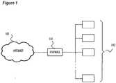
- Figure 1illustrates a typical computer network environment, including a public network such as the Internet at 101, a private network 102, and a computer network device operable to provide firewall and intrusion protection functions shown at 103.
- the computer network device 103is positioned between the Internet and the private network, and regulates the flow of traffic between the private network and the public network.
- the network device 103is in various embodiments a firewall device, and intrusion protection device, or functions as both.
- a firewall device or module within the network deviceprovides various network flow control functions, such as inspecting network packets and dropping or rejecting network packets that meet a set of firewall filtering rules.
- firewallstypically perform their filtering functions by observing communication packets, such as TCP/IP or other network protocol packets, and examining characteristics such as the source and destination network addresses, what ports are being used, and the state or history of the connection. Some firewalls also examine packets to determine what application has established the connection, or act as a proxy device by processing and forwarding selected network requests between a protected user and external networked computers.
- Firewallsoften use "signatures" or other characteristics of undesired traffic to detect and block traffic that is deemed harmful or that is otherwise undesired.
- Firewallstypically use sets of rules to filter traffic, such that what happens with any particular element of network data is dependent on how the rule set applies to that particular data. For example a rule blocking all traffic to port 6346 will block incoming traffic bound for that port on a server within the protected network, but will not block other data going to the same server on a different port number. Similarly, a rule blocking traffic originating from a file sharing program such as Shareaza will use patterns in the traffic to block Shareaza traffic on port 6346, but allow other traffic on port 6346.
- a rule blocking traffic originating from a file sharing programsuch as Shareaza will use patterns in the traffic to block Shareaza traffic on port 6346, but allow other traffic on port 6346.
- Some embodiments of the inventiontherefore provide a mechanism for sharing state information such as user or other such connection data with other systems in a cluster firewall, enabling multiple nodes in the firewall cluster to process the same connection. This provides the cluster the ability to load balance by moving connection responsibility between systems, to manage failure of a node in the cluster by moving its connections to another machine, and to perform other such functions.
- a firewall or intrusion protection systemis implemented as a cluster or connected group of nodes that share processing traffic flowing through the firewall.
- Figure 2shows a network with a distributed firewall, as may be used to practice some embodiments of the invention.
- a networksuch as the Internet 201 is coupled to an internal network 202 by a firewall, 203.
- the firewall 203comprises an incoming traffic module 204 and an outgoing traffic module 205 that can perform functions such as load balancing and other firewall management functions.
- the firewall or intrusion protection rulesare applied in firewall nodes 206, which are connected to one another by network connections as shown.
- the five nodes showneach comprise a separate computer system running an instance of firewall or related software, operable to apply rules to traffic to selectively permit or block traffic flowing between the Internet 201 and the internal network 202.
- some nodessuch as nodes 1, 2, and 3 execute a firewall application, while other nodes such as 4 and 5 execute an intrusion protection system (IPS) application.
- IPSintrusion protection system
- the nodes 204 and 205are responsible for performing functions such as load balancing traffic routed to the firewall nodes 206, ensuring that the nodes are able to work together efficiently to provide higher throughput capability than a single node.
- Some firewall embodimentsperform complex connection identification functions that go beyond simple application of port, IP, and other such rules to a data stream.
- some firewall examplesinclude a user "passport", associating a user with a particular connection by using user authentication to the firewall, or using indirect user authentication such as a Microsoft domain server logon or other user credential that can be read by the firewall.
- This passportassociates an identified user with a particular IP address, MAC address, or other identifier so that connections coming from the user can be identified as belonging to the user.
- a firewallmay know that Alice is a member of a management group, while Bob is a member of the employees group but not management. Both users log on to computers and run Skype to join a video conference, and the firewall determines that both users are permitted to use Skype to send videoconference traffic through the firewall, such as to videoconference with outside vendors or customers.
- the firewalluses the passport user and IP address information associated with Bob's connection to determine that Bob is the one attempting to send the file, and therefore blocks Bob's file. Alice then tries to send the same file using Skype, and the passport associated with Alice's connection identifies Alice as the user associated with the connection and permits the file to be sent.
- Some embodiments of the inventiontherefore comprise distributing the user passport information between nodes in a firewall cluster, such as by multicasting the user passport information or sending the user passport information to a master node for distribution.
- FIG. 3is a flowchart illustrating use of shared user passport information in a firewall cluster, consistent with an example embodiment of the invention.
- a linkis initiated between a computer in local network 202 and the Internet 201.
- the link between nodesis handled by node 1, which retrieves user passport information such as from a Microsoft domain server login or the user logging directly into the firewall as soon as the network connection is established at 302.
- the firewall node 1then shares this user passport data for the connection with other nodes at 303, and uses the user passport data to apply user-specific rules to the firewall at 304.
- node 1fails, and the connection is redirected to node 2 at 306. Because node 2 has received user passport data regarding the connection from node 1 previously, node 2 is able to resume filtering the data stream including applying user-specific rules to the connection at 308.
- firewall node 1does not fail, but an intrusion protection system node that is one of two such nodes (not pictured) fails.
- the systemdesires to maintain a certain balance between the number of nodes providing firewall service and the number of nodes providing intrusion protection, and in this example the intrusion protection system has lost half its capacity when one of its two nodes failed.
- the systemtherefore reassigns firewall node 1 to replace the failed intrusion protection node, resulting in connections previously handled by firewall node 1 being redistributed across firewall nodes 2-5, as shown in Figure 2 .
- a method of operating a firewall clustercan include receiving a connection in a first node of a firewall cluster having three or more nodes; determining user data associated with the connection; and sharing the user data with at least another node in the firewall cluster. Additionally, the firewall cluster can share connection information regarding the received connection with at least another node in the firewall cluster after receiving the connection but before sharing the user data.
- the user datacan include the identity of the user and an IP address of the connection. Sharing can include broadcasting the user data to the other nodes in the firewall cluster or sending the user data to a master node. The master node can also be configured for broadcasting the user data to other nodes in the firewall cluster.
- the firewall clustercould use the shared user data associated with the connection to filter the connection in another node upon failure of the first node or to filter the connection in another node to provide load balancing in the firewall cluster.
- a method of operating a firewall clustercomprises receiving a connection in a first node of a firewall cluster having three or more nodes; determining user data associated with the connection; and sharing the user data with at least another node in the firewall cluster.
- the methodfurther comprises sharing connection information regarding the received connection with at least another node in the firewall cluster after receiving the connection but before sharing the user data.
- the user datacomprises the identity of the user and an IP address of the connection.
- sharing user datacomprises broadcasting the user data to the other nodes in the firewall cluster.
- sharing user datacomprises sending the user data to a master node.
- the methodfurther comprises the master node broadcasting the user data to other nodes in the firewall cluster.
- the methodfurther comprises using the shared user data associated with the connection to filter the connection in another node upon failure of the first node.
- the methodfurther comprises using the shared user data associated with the connection to filter the connection in another node to provide load balancing in the firewall cluster.
- a firewall clustercomprises a first node operable to receive a connection in a firewall cluster having three or more nodes, determine user data associated with the connection, and share the user data with at least another node in the firewall cluster.
- the first nodeis further operable to share connection information regarding the received connection with at least another node in the firewall cluster after receiving the connection but before sharing user data.
- user datacomprises the identity of a user and an IP address associated with the connection.
- sharing user datacomprises broadcasting the user data to the other nodes in the firewall cluster.
- the firewall clusterfurther comprises a master node, and wherein sharing user data comprises sending the user data to the master node.
- the master nodeis further operable to broadcast the user data to other nodes in the firewall cluster.
- the firewall clusterfurther comprises a second node operable to use the shared user data associated with the connection to filter the connection in another node upon failure of the first node.
- the firewall clusterfurther comprises a second node operable to use the shared user data associated with the connection to filter the connection in another node to provide load balancing in the firewall cluster.
- a method of operating a firewall clustercomprises receiving a connection in a first node of a firewall cluster having three or more nodes; sharing connection data regarding the received connection with at least another node in the firewall cluster; determining user data associated with the connection; and sharing the user data associated with the connection with two or more other nodes in the firewall cluster.
- the methodfurther comprises using the shared user data to filter the connection in another node upon failure of the first node.
- the methodfurther comprises using the shared user data to filter the connection in another node to provide load balancing in the firewall cluster.
Landscapes
- Engineering & Computer Science (AREA)
- Computer Networks & Wireless Communication (AREA)
- Signal Processing (AREA)
- Computer Hardware Design (AREA)
- Computer Security & Cryptography (AREA)
- General Engineering & Computer Science (AREA)
- Computing Systems (AREA)
- Power Engineering (AREA)
- Data Exchanges In Wide-Area Networks (AREA)
- Computer And Data Communications (AREA)
Description
- This application claims priority to
U.S Application No13/227,848, filed on September 8, 2011 - The invention relates generally to firewall operation, and more specifically in one embodiment to authentication sharing in a firewall cluster.
- A portion of the disclosure of this patent document contains material to which the claim of copyright protection is made. The copyright owner has no objection to the facsimile reproduction by any person of the patent document or the patent disclosure, as it appears in the U.S. Patent and Trademark Office file or records, but reserves all other rights whatsoever.
- Computers are valuable tools in large part for their ability to communicate with other computer systems and retrieve information over computer networks. Networks typically comprise an interconnected group of computers, linked by wire, fiber optic, radio, or other data transmission means, to provide the computers with the ability to transfer information from computer to computer. The Internet is perhaps the best-known computer network, and enables millions of people to access millions of other computers such as by viewing web pages, sending e-mail, or by performing other computer-to-computer communication.
- But, because the size of the Internet is so large and Internet users are so diverse in their interests, it is not uncommon for malicious users or pranksters to attempt to communicate with other users' computers in a manner that poses a danger to the other users. For example, a hacker may attempt to log in to a corporate computer to steal, delete, or change information. Computer viruses or Trojan horse programs may be distributed to other computers, or unknowingly downloaded or executed by large numbers of computer users. Further, computer users within an organization such as a corporation may on occasion attempt to perform unauthorized network communications, such as running file sharing programs or transmitting corporate secrets from within the corporation's network to the Internet.
- For these and other reasons, many corporations, institutions, and even home users use a network firewall or similar device between their local network and the Internet. The firewall is typically a computerized network device that inspects network traffic that passes through it, permitting passage of desired network traffic based on a set of rules.
- Firewalls perform their filtering functions by observing communication packets, such as TCP/IP or other network protocol packets, and examining characteristics such as the source and destination network addresses, what ports are being used, and the state or history of the connection. Some firewalls also examine packets traveling to or from a particular application, or act as a proxy device by processing and forwarding selected network requests between a protected user and external networked computers.
- The firewall typically controls the flow of network information by monitoring connections between various ports, sockets, and protocols, such as by examining the network traffic in a firewall. Rules based on socket, port, application, and other information are used to selectively filter or pass data, and to log network activity. Firewall rules are typically configured to identify certain types of network traffic that are to be prohibited or that should have certain other restrictions applied, such as blocking traffic on ports known to be used for file sharing programs while virus scanning any received over a traditional FTP port, blocking certain applications or users from performing some tasks while allowing others to perform such tasks, and blocking traffic based on known attack patterns such as repeated queries to different ports from a common IP address.
- But, the ability of a firewall to manage such connections when distributed across multiple computer systems is limited in that knowledge of a connection is typically stored only in the system handling the connection. Improved firewall distribution in a cluster is therefore desired.
WO 2008/049094 A2 discloses sharing a state of a data packet between multiple servers within a cluster. This information can be used to avoid the loss of the data packet in case of a server failure. A master node of a cluster is reassigned to a slave node if the original master node fails.US 2006/195896 A1 discloses sharing state information that includes source and destination addresses, port numbers, sequencing information, and connection flags.- 3AFigure 1 shows an example network including a firewall, as may be used to practice some embodiments of the invention.
Figure 2 shows an example network including a firewall cluster comprising multiple firewall nodes, as may be used to practice some embodiments of the invention.Figure 3 is a flowchart illustrating use of shared user passport information in a firewall cluster, consistent with an example embodiment of the invention.- The invention is defined in the appended claims.
- In the following detailed description of example embodiments of the invention, reference is made to specific examples by way of drawings and illustrations. These examples are described in sufficient detail to enable those skilled in the art to practice the invention, and serve to illustrate how the invention may be applied to various purposes or embodiments. Other embodiments of the invention exist and are within the scope of the invention, and logical, mechanical, electrical, and other changes may be made without departing from the subject or scope of the present invention. Features or limitations of various embodiments of the invention described herein, however essential to the example embodiments in which they are incorporated, do not limit the invention as a whole, and any reference to the invention, its elements, operation, and application do not limit the invention as a whole but serve only to define these example embodiments. The following detailed description does not, therefore, limit the scope of the invention, which is defined only by the appended claims.
Figure 1 illustrates a typical computer network environment, including a public network such as the Internet at 101, aprivate network 102, and a computer network device operable to provide firewall and intrusion protection functions shown at 103. In this particular example, thecomputer network device 103 is positioned between the Internet and the private network, and regulates the flow of traffic between the private network and the public network.- The
network device 103 is in various embodiments a firewall device, and intrusion protection device, or functions as both. A firewall device or module within the network device provides various network flow control functions, such as inspecting network packets and dropping or rejecting network packets that meet a set of firewall filtering rules. As described previously, firewalls typically perform their filtering functions by observing communication packets, such as TCP/IP or other network protocol packets, and examining characteristics such as the source and destination network addresses, what ports are being used, and the state or history of the connection. Some firewalls also examine packets to determine what application has established the connection, or act as a proxy device by processing and forwarding selected network requests between a protected user and external networked computers. Firewalls often use "signatures" or other characteristics of undesired traffic to detect and block traffic that is deemed harmful or that is otherwise undesired. - Firewalls typically use sets of rules to filter traffic, such that what happens with any particular element of network data is dependent on how the rule set applies to that particular data. For example a rule blocking all traffic to port 6346 will block incoming traffic bound for that port on a server within the protected network, but will not block other data going to the same server on a different port number. Similarly, a rule blocking traffic originating from a file sharing program such as Shareaza will use patterns in the traffic to block Shareaza traffic on port 6346, but allow other traffic on port 6346.
- But, in an environment where a firewall is implemented as a system distributed across multiple computers or nodes, such as in a large or complex system, the ability of multiple nodes to share a connection is limited by each node's information regarding the connection, such as socket information, application information, user information, and the like regarding the connection. Some embodiments of the invention therefore provide a mechanism for sharing state information such as user or other such connection data with other systems in a cluster firewall, enabling multiple nodes in the firewall cluster to process the same connection. This provides the cluster the ability to load balance by moving connection responsibility between systems, to manage failure of a node in the cluster by moving its connections to another machine, and to perform other such functions.
- In one such example, a firewall or intrusion protection system is implemented as a cluster or connected group of nodes that share processing traffic flowing through the firewall.
Figure 2 shows a network with a distributed firewall, as may be used to practice some embodiments of the invention. Here, a network such as the Internet 201 is coupled to aninternal network 202 by a firewall, 203. Thefirewall 203 comprises anincoming traffic module 204 and anoutgoing traffic module 205 that can perform functions such as load balancing and other firewall management functions. The firewall or intrusion protection rules are applied infirewall nodes 206, which are connected to one another by network connections as shown. - Here the five nodes shown each comprise a separate computer system running an instance of firewall or related software, operable to apply rules to traffic to selectively permit or block traffic flowing between the Internet 201 and the
internal network 202. In an alternate embodiment, some nodes such asnodes nodes firewall nodes 206, ensuring that the nodes are able to work together efficiently to provide higher throughput capability than a single node. - Some firewall embodiments perform complex connection identification functions that go beyond simple application of port, IP, and other such rules to a data stream. For example, some firewall examples include a user "passport", associating a user with a particular connection by using user authentication to the firewall, or using indirect user authentication such as a Microsoft domain server logon or other user credential that can be read by the firewall. This passport associates an identified user with a particular IP address, MAC address, or other identifier so that connections coming from the user can be identified as belonging to the user.
- User-based filtering can then be performed in the firewall. For example, a firewall may know that Alice is a member of a management group, while Bob is a member of the employees group but not management. Both users log on to computers and run Skype to join a video conference, and the firewall determines that both users are permitted to use Skype to send videoconference traffic through the firewall, such as to videoconference with outside vendors or customers.
- Bob attempts to send a file using Skype, and the firewall applies a rule permitting only members of the managers group to send files outbound using Skype. The firewall uses the passport user and IP address information associated with Bob's connection to determine that Bob is the one attempting to send the file, and therefore blocks Bob's file. Alice then tries to send the same file using Skype, and the passport associated with Alice's connection identifies Alice as the user associated with the connection and permits the file to be sent.
- But, if the firewall is distributed across multiple nodes, applying the appropriate rule to the connection becomes more difficult in that while each node has the same firewall rules, only the node managing the connection knows user information such as the user name and IP address (or passport) for the connection.
- Some embodiments of the invention therefore comprise distributing the user passport information between nodes in a firewall cluster, such as by multicasting the user passport information or sending the user passport information to a master node for distribution.
Figure 3 is a flowchart illustrating use of shared user passport information in a firewall cluster, consistent with an example embodiment of the invention. At 301, a link is initiated between a computer inlocal network 202 and theInternet 201. The link between nodes is handled by node 1, which retrieves user passport information such as from a Microsoft domain server login or the user logging directly into the firewall as soon as the network connection is established at 302. The firewall node 1 then shares this user passport data for the connection with other nodes at 303, and uses the user passport data to apply user-specific rules to the firewall at 304.- At 305, node 1 fails, and the connection is redirected to
node 2 at 306. Becausenode 2 has received user passport data regarding the connection from node 1 previously,node 2 is able to resume filtering the data stream including applying user-specific rules to the connection at 308. - Although this example illustrates how a node can resume filtering a connection after a node fails, similar methods can be employed to move connections from one node to another in a distributed firewall cluster for applications such as load balancing, or reassignment of nodes to different tasks.
- In one such example, firewall node 1 does not fail, but an intrusion protection system node that is one of two such nodes (not pictured) fails. The system desires to maintain a certain balance between the number of nodes providing firewall service and the number of nodes providing intrusion protection, and in this example the intrusion protection system has lost half its capacity when one of its two nodes failed. The system therefore reassigns firewall node 1 to replace the failed intrusion protection node, resulting in connections previously handled by firewall node 1 being redistributed across firewall nodes 2-5, as shown in
Figure 2 . - These examples illustrate how sharing user passport data in a firewall cluster can facilitate load balancing, failover, and other functions within the firewall cluster, making user-based filtering of network traffic in a firewall cluster more manageable and reliable.
- Although specific embodiments have been illustrated and described herein, it will be appreciated by those of ordinary skill in the art that any arrangement which is calculated to achieve the same purpose may be substituted for the specific embodiments shown. This application is intended to cover any adaptations or variations of the example embodiments of the invention described herein. It is intended that this invention be limited only by the claims, and the full scope of equivalents thereof.
- As described above methods of operating and firewalls configured in certain ways have been disclosed. For example, a method of operating a firewall cluster can include receiving a connection in a first node of a firewall cluster having three or more nodes; determining user data associated with the connection; and sharing the user data with at least another node in the firewall cluster. Additionally, the firewall cluster can share connection information regarding the received connection with at least another node in the firewall cluster after receiving the connection but before sharing the user data. The user data can include the identity of the user and an IP address of the connection. Sharing can include broadcasting the user data to the other nodes in the firewall cluster or sending the user data to a master node. The master node can also be configured for broadcasting the user data to other nodes in the firewall cluster. Optionally, the firewall cluster could use the shared user data associated with the connection to filter the connection in another node upon failure of the first node or to filter the connection in another node to provide load balancing in the firewall cluster.
- According to an aspect of the present invention, a method of operating a firewall cluster comprises receiving a connection in a first node of a firewall cluster having three or more nodes; determining user data associated with the connection; and sharing the user data with at least another node in the firewall cluster.
- According to one embodiment, the method further comprises sharing connection information regarding the received connection with at least another node in the firewall cluster after receiving the connection but before sharing the user data.
- In one embodiment, the user data comprises the identity of the user and an IP address of the connection.
- In one embodiment, sharing user data comprises broadcasting the user data to the other nodes in the firewall cluster.
- In another embodiment, sharing user data comprises sending the user data to a master node.
- According to one embodiment, the method further comprises the master node broadcasting the user data to other nodes in the firewall cluster.
- According to another embodiment, the method further comprises using the shared user data associated with the connection to filter the connection in another node upon failure of the first node.
- In an embodiment, the method further comprises using the shared user data associated with the connection to filter the connection in another node to provide load balancing in the firewall cluster.
- According to a further aspect of the present invention, a firewall cluster comprises a first node operable to receive a connection in a firewall cluster having three or more nodes, determine user data associated with the connection, and share the user data with at least another node in the firewall cluster.
- In one embodiment, the first node is further operable to share connection information regarding the received connection with at least another node in the firewall cluster after receiving the connection but before sharing user data.
- According to one embodiment, user data comprises the identity of a user and an IP address associated with the connection.
- According to yet another embodiment, sharing user data comprises broadcasting the user data to the other nodes in the firewall cluster.
- In one embodiment, the firewall cluster further comprises a master node, and wherein sharing user data comprises sending the user data to the master node.
- According to one embodiment, the master node is further operable to broadcast the user data to other nodes in the firewall cluster.
- In one embodiment, the firewall cluster further comprises a second node operable to use the shared user data associated with the connection to filter the connection in another node upon failure of the first node.
- In one embodiment, the firewall cluster further comprises a second node operable to use the shared user data associated with the connection to filter the connection in another node to provide load balancing in the firewall cluster.
- According to another aspect of the present invention, a method of operating a firewall cluster, comprises receiving a connection in a first node of a firewall cluster having three or more nodes; sharing connection data regarding the received connection with at least another node in the firewall cluster; determining user data associated with the connection; and sharing the user data associated with the connection with two or more other nodes in the firewall cluster.
- In one embodiment, the method further comprises using the shared user data to filter the connection in another node upon failure of the first node.
- According to one embodiment, the method further comprises using the shared user data to filter the connection in another node to provide load balancing in the firewall cluster.
Claims (17)
- A computer program, including instructions that, when executed, cause a computer system to at least:process a connection request to establish a connection, the connection request received at a first node of a firewall cluster having three or more nodes, some of the nodes to perform a firewall application and others of the nodes to perform an intrusion protection task, the first node to perform a firewall task;share state information, associated with the established connection, with at least a second node in the firewall cluster;reassign, in response to failure of a third node configured to perform an intrusion protection task, the first node to perform the intrusion protection task, andassign the second node in the firewall cluster to process the established connection based on the shared state information;wherein the state information associates an identified user with the established connection.
- The computer program of claim 1, wherein the instructions are to further cause the computer system to share connection information regarding the connection request with at least another node in the firewall cluster after receiving the connection request but before sharing the state information.
- The computer program of claim 1 or claim 2, wherein the state information comprises an identity of a user and an IP address, each associated with the connection request.
- The computer program according to one or more of the preceding claims, wherein the instructions cause the computer system to share the state information by broadcasting the state information to a plurality of other nodes in the firewall cluster.
- The computer program according to one or more of the preceding claims, wherein the instructions cause the computer system to share the state information by sending the state information to a primary node, and the instructions are to further cause the computer system to broadcast the state information from the primary node to other nodes in the firewall cluster.
- The computer program according to one or more of the preceding claims, wherein the instructions are to further cause the computer system to use the shared state information associated with the established connection to filter a corresponding subsequently established connection in the second node upon failure of the first node, or to filter a corresponding subsequently established connection in the second node to provide load balancing in the firewall cluster.
- The computer program according to one or more of the preceding claims, wherein the instructions cause the computer system to process the connection request by determining the shared state information prior to forming the established connection.
- A method of operating a cluster of nodes, comprising:receiving a connection request at a first node of the cluster of nodes, the cluster of nodes having three or more nodes, some of the nodes to perform a firewall application and others of the nodes to perform an intrusion protection task, the first node performing a firewall task;processing the connection request to establish a connection;sharing state information associated with the established connection with at least a second node in the firewall cluster;reassigning the first node to perform an intrusion protection task responsive to failure of a third node configured to perform the intrusion protection task, andassign the second node in the firewall cluster to process the established connection based on the shared state information;wherein the state information associates an identified user with the established connection.
- The method of claim 8, further comprising sharing connection information regarding the received connection request with at least another node in the cluster of nodes after receiving the connection request but before sharing the state information.
- The method of claim 8 or claim 9, wherein the state information comprises an identity of a user and an IP address, each associated with the connection request.
- The method of any of claims 8-10, wherein sharing the state information comprises one or more of:broadcasting the state information to a plurality of other nodes in the cluster of nodes;sending the state information to a primary node; andbroadcasting the state information from the primary node to other nodes in the cluster of nodes.
- The method of any of claims 8-10, further comprising load balancing the cluster of nodes by filtering a corresponding subsequently established connection in the second node using the shared state information associated with the established connection, or
wherein processing the connection request comprises determining the state information prior to establishing the connection. - A firewall cluster, comprising:a first node, a second node, and a third node, wherein the first node and the second node are configured to execute a firewall task and the third node is configured to execute an intrusion protection task;wherein the first node is further configured to:receive a connection request;process the connection request to establish a connection;share state information associated with the established connection with the second node for processing the established connection using the shared state information; andreassign the first node to perform the intrusion protection task responsive to failure of the third node, resulting in the second node assigned to process the established connection,wherein the state information associates an identified user with the established connection.
- The firewall cluster of claim 13, wherein the first node is further configured to share connection information regarding the received connection request with at least another node in the firewall cluster after receiving the connection request but before sharing the state information, or
wherein the first node is configured to share the state information by broadcasting the state information to a plurality of other nodes in the firewall cluster. - The firewall cluster of claim 13 or claim 14, wherein a primary node is configured to broadcast the shared state information to other nodes in the firewall cluster.
- The firewall cluster of any of claims 13-15, further comprising a load balancer configured to provide load balancing in the firewall cluster by filtering a subsequently established connection in the second node using the shared state information.
- The firewall cluster of any of claims 13-16, wherein the first node is further configured to determine the shared state information prior to forming the established connection, or
wherein the second node is further configured to filter a subsequently established connection in the second node upon failure of the first node.
Applications Claiming Priority (3)
| Application Number | Priority Date | Filing Date | Title |
|---|---|---|---|
| US13/227,848US8887263B2 (en) | 2011-09-08 | 2011-09-08 | Authentication sharing in a firewall cluster |
| EP12830232.0AEP2754266B1 (en) | 2011-09-08 | 2012-09-06 | Authentication sharing in a firewall cluster |
| PCT/US2012/053976WO2013036651A1 (en) | 2011-09-08 | 2012-09-06 | Authentication sharing in a firewall cluster |
Related Parent Applications (2)
| Application Number | Title | Priority Date | Filing Date |
|---|---|---|---|
| EP12830232.0ADivisionEP2754266B1 (en) | 2011-09-08 | 2012-09-06 | Authentication sharing in a firewall cluster |
| EP12830232.0ADivision-IntoEP2754266B1 (en) | 2011-09-08 | 2012-09-06 | Authentication sharing in a firewall cluster |
Publications (2)
| Publication Number | Publication Date |
|---|---|
| EP2991276A1 EP2991276A1 (en) | 2016-03-02 |
| EP2991276B1true EP2991276B1 (en) | 2022-04-06 |
Family
ID=47831093
Family Applications (2)
| Application Number | Title | Priority Date | Filing Date |
|---|---|---|---|
| EP12830232.0AActiveEP2754266B1 (en) | 2011-09-08 | 2012-09-06 | Authentication sharing in a firewall cluster |
| EP15190769.8AActiveEP2991276B1 (en) | 2011-09-08 | 2012-09-06 | Authentication sharing in a firewall cluster |
Family Applications Before (1)
| Application Number | Title | Priority Date | Filing Date |
|---|---|---|---|
| EP12830232.0AActiveEP2754266B1 (en) | 2011-09-08 | 2012-09-06 | Authentication sharing in a firewall cluster |
Country Status (6)
| Country | Link |
|---|---|
| US (1) | US8887263B2 (en) |
| EP (2) | EP2754266B1 (en) |
| JP (1) | JP5908090B2 (en) |
| KR (2) | KR101586972B1 (en) |
| CN (2) | CN105407099B (en) |
| WO (1) | WO2013036651A1 (en) |
Families Citing this family (7)
| Publication number | Priority date | Publication date | Assignee | Title |
|---|---|---|---|---|
| US8887263B2 (en) | 2011-09-08 | 2014-11-11 | Mcafee, Inc. | Authentication sharing in a firewall cluster |
| US8763106B2 (en) | 2011-09-08 | 2014-06-24 | Mcafee, Inc. | Application state sharing in a firewall cluster |
| US10554760B2 (en) | 2013-09-29 | 2020-02-04 | Xiaomi Inc. | Method and networking equipment for acquiring feature information |
| CN103475577B (en)* | 2013-09-29 | 2017-02-08 | 小米科技有限责任公司 | Method, device and network equipment for obtaining characteristic information |
| US9609031B1 (en)* | 2013-12-17 | 2017-03-28 | Amazon Technologies, Inc. | Propagating state information to network nodes |
| US10594656B2 (en)* | 2015-11-17 | 2020-03-17 | Zscaler, Inc. | Multi-tenant cloud-based firewall systems and methods |
| US10757105B2 (en)* | 2017-06-12 | 2020-08-25 | At&T Intellectual Property I, L.P. | On-demand network security system |
Family Cites Families (43)
| Publication number | Priority date | Publication date | Assignee | Title |
|---|---|---|---|---|
| US6791947B2 (en)* | 1996-12-16 | 2004-09-14 | Juniper Networks | In-line packet processing |
| US6880089B1 (en) | 2000-03-31 | 2005-04-12 | Avaya Technology Corp. | Firewall clustering for multiple network servers |
| US6772226B1 (en) | 2000-08-15 | 2004-08-03 | Avaya Technology Corp. | VPN device clustering using a network flow switch and a different mac address for each VPN device in the cluster |
| JP3663121B2 (en)* | 2000-10-30 | 2005-06-22 | シャープ株式会社 | Node configuration information management method and wireless network system |
| US7131140B1 (en) | 2000-12-29 | 2006-10-31 | Cisco Technology, Inc. | Method for protecting a firewall load balancer from a denial of service attack |
| US7130305B2 (en) | 2001-07-02 | 2006-10-31 | Stonesoft Oy | Processing of data packets within a network element cluster |
| US7107609B2 (en) | 2001-07-20 | 2006-09-12 | Hewlett-Packard Development Company, L.P. | Stateful packet forwarding in a firewall cluster |
| JP4716473B2 (en)* | 2001-08-08 | 2011-07-06 | 独立行政法人電子航法研究所 | Wireless communication network system |
| WO2003034237A1 (en)* | 2001-10-18 | 2003-04-24 | The Board Of Regents Of The University Of Nebraska | Fault tolerant firewall sandwiches |
| US7447901B1 (en) | 2002-06-25 | 2008-11-04 | Cisco Technology, Inc. | Method and apparatus for establishing a dynamic multipoint encrypted virtual private network |
| US6874031B2 (en)* | 2002-10-07 | 2005-03-29 | Qualcomm Inc. | Method and apparatus for sharing authentication session state in a global distributed network |
| EP1566034B1 (en)* | 2002-11-27 | 2007-04-04 | Fujitsu Siemens Computers, Inc. | Method and appliance for distributing data packets sent by a computer to a cluster system |
| US7735129B2 (en)* | 2003-02-05 | 2010-06-08 | Nippon Telegraph And Telephone Corporation | Firewall device |
| US7266715B1 (en) | 2003-04-29 | 2007-09-04 | Cisco Technology, Inc. | Methods and apparatus for maintaining a virtual private network connection |
| US7844731B1 (en) | 2003-11-14 | 2010-11-30 | Symantec Corporation | Systems and methods for address spacing in a firewall cluster |
| US20050240989A1 (en) | 2004-04-23 | 2005-10-27 | Seoul National University Industry Foundation | Method of sharing state between stateful inspection firewalls on mep network |
| JP2006054770A (en)* | 2004-08-16 | 2006-02-23 | Yokogawa Electric Corp | Firewall device |
| US8146145B2 (en) | 2004-09-30 | 2012-03-27 | Rockstar Bidco Lp | Method and apparatus for enabling enhanced control of traffic propagation through a network firewall |
| AU2005328336B2 (en) | 2004-12-22 | 2011-09-15 | Wake Forest University | Method, systems, and computer program products for implementing function-parallel network firewall |
| US7870602B2 (en)* | 2005-09-14 | 2011-01-11 | At&T Intellectual Property I, L.P. | System and method for reducing data stream interruption during failure of a firewall device |
| US8533808B2 (en)* | 2006-02-02 | 2013-09-10 | Check Point Software Technologies Ltd. | Network security smart load balancing using a multiple processor device |
| US9137204B2 (en)* | 2006-02-02 | 2015-09-15 | Check Point Software Technologies Ltd. | Network security smart load balancing |
| US8353020B2 (en) | 2006-06-14 | 2013-01-08 | Microsoft Corporation | Transparently extensible firewall cluster |
| US20080098113A1 (en)* | 2006-10-19 | 2008-04-24 | Gert Hansen | Stateful firewall clustering for processing-intensive network applications |
| US8255985B2 (en) | 2006-11-13 | 2012-08-28 | At&T Intellectual Property I, L.P. | Methods, network services, and computer program products for recommending security policies to firewalls |
| US7685274B2 (en)* | 2006-12-22 | 2010-03-23 | General Electric Company | Method and apparatus for clustered filtering in an RFID infrastructure |
| CN101014048B (en)* | 2007-02-12 | 2010-05-19 | 杭州华三通信技术有限公司 | Distributed firewall system and method for realizing content diction of firewall |
| US7822841B2 (en) | 2007-10-30 | 2010-10-26 | Modern Grids, Inc. | Method and system for hosting multiple, customized computing clusters |
| CN101179514B (en)* | 2007-12-18 | 2010-08-18 | 杭州华三通信技术有限公司 | Method and device of maintaining MAC item of distributed network processing system |
| US8015298B2 (en)* | 2008-02-28 | 2011-09-06 | Level 3 Communications, Llc | Load-balancing cluster |
| CN101350773A (en)* | 2008-06-20 | 2009-01-21 | 中兴通讯股份有限公司 | Mobile packet network architecture as well as access method for equalizing load of a plurality of firewalls |
| US7936685B2 (en)* | 2009-01-15 | 2011-05-03 | Vss Monitoring, Inc. | Intelligent fast switch-over network tap system and methods |
| CN101651680A (en)* | 2009-09-14 | 2010-02-17 | 杭州华三通信技术有限公司 | Network safety allocating method and network safety device |
| US8493902B2 (en) | 2010-08-16 | 2013-07-23 | Florida Institute for Human and Machine Cognition | Opportunistic listening system and method |
| US8406233B2 (en)* | 2010-09-07 | 2013-03-26 | Check Point Software Technologies Ltd. | Predictive synchronization for clustered devices |
| CN102025735B (en)* | 2010-12-08 | 2013-04-24 | 北京航空航天大学 | Distributed network firewall system of Linux based on defense strategy |
| US8776207B2 (en)* | 2011-02-16 | 2014-07-08 | Fortinet, Inc. | Load balancing in a network with session information |
| US9047441B2 (en)* | 2011-05-24 | 2015-06-02 | Palo Alto Networks, Inc. | Malware analysis system |
| GB2503625A (en)* | 2011-07-08 | 2014-01-01 | Box Inc | Collaboration sessions in a workspace on cloud-based content management system |
| US8763106B2 (en) | 2011-09-08 | 2014-06-24 | Mcafee, Inc. | Application state sharing in a firewall cluster |
| US8887263B2 (en) | 2011-09-08 | 2014-11-11 | Mcafee, Inc. | Authentication sharing in a firewall cluster |
| US9319459B2 (en) | 2011-09-19 | 2016-04-19 | Cisco Technology, Inc. | Services controlled session based flow interceptor |
| US20130152156A1 (en) | 2011-12-12 | 2013-06-13 | Mcafee, Inc. | Vpn support in a large firewall cluster |
- 2011
- 2011-09-08USUS13/227,848patent/US8887263B2/ennot_activeExpired - Fee Related
- 2012
- 2012-09-06CNCN201510869336.6Apatent/CN105407099B/enactiveActive
- 2012-09-06CNCN201280043917.9Apatent/CN103858383B/enactiveActive
- 2012-09-06KRKR1020147037044Apatent/KR101586972B1/enactiveActive
- 2012-09-06EPEP12830232.0Apatent/EP2754266B1/enactiveActive
- 2012-09-06EPEP15190769.8Apatent/EP2991276B1/enactiveActive
- 2012-09-06JPJP2014529857Apatent/JP5908090B2/enactiveActive
- 2012-09-06WOPCT/US2012/053976patent/WO2013036651A1/enactiveApplication Filing
- 2012-09-06KRKR1020147006135Apatent/KR101529839B1/enactiveActive
Also Published As
| Publication number | Publication date |
|---|---|
| JP5908090B2 (en) | 2016-04-26 |
| KR20150015027A (en) | 2015-02-09 |
| CN105407099B (en) | 2019-01-08 |
| KR20140058616A (en) | 2014-05-14 |
| CN103858383A (en) | 2014-06-11 |
| US8887263B2 (en) | 2014-11-11 |
| KR101586972B1 (en) | 2016-02-02 |
| CN103858383B (en) | 2017-04-19 |
| KR101529839B1 (en) | 2015-06-17 |
| JP2014526739A (en) | 2014-10-06 |
| WO2013036651A1 (en) | 2013-03-14 |
| EP2754266B1 (en) | 2019-01-09 |
| EP2754266A1 (en) | 2014-07-16 |
| EP2754266A4 (en) | 2015-05-13 |
| US20130067557A1 (en) | 2013-03-14 |
| EP2991276A1 (en) | 2016-03-02 |
| CN105407099A (en) | 2016-03-16 |
Similar Documents
| Publication | Publication Date | Title |
|---|---|---|
| US9876763B2 (en) | Application state sharing in a firewall cluster | |
| US8887265B2 (en) | Named sockets in a firewall | |
| EP2991276B1 (en) | Authentication sharing in a firewall cluster | |
| US20130152156A1 (en) | Vpn support in a large firewall cluster | |
| US10721209B2 (en) | Timing management in a large firewall cluster | |
| US8677471B2 (en) | Port allocation in a firewall cluster |
Legal Events
| Date | Code | Title | Description |
|---|---|---|---|
| PUAI | Public reference made under article 153(3) epc to a published international application that has entered the european phase | Free format text:ORIGINAL CODE: 0009012 | |
| AC | Divisional application: reference to earlier application | Ref document number:2754266 Country of ref document:EP Kind code of ref document:P | |
| AK | Designated contracting states | Kind code of ref document:A1 Designated state(s):AL AT BE BG CH CY CZ DE DK EE ES FI FR GB GR HR HU IE IS IT LI LT LU LV MC MK MT NL NO PL PT RO RS SE SI SK SM TR | |
| RIN1 | Information on inventor provided before grant (corrected) | Inventor name:THOMAS, ANISH Inventor name:NISSEN, ANDREW Inventor name:SILBERSACK, MICHAEL, JAMES Inventor name:ALLISON, TYLOR | |
| 17P | Request for examination filed | Effective date:20160902 | |
| RBV | Designated contracting states (corrected) | Designated state(s):AL AT BE BG CH CY CZ DE DK EE ES FI FR GB GR HR HU IE IS IT LI LT LU LV MC MK MT NL NO PL PT RO RS SE SI SK SM TR | |
| RAP1 | Party data changed (applicant data changed or rights of an application transferred) | Owner name:MCAFEE, LLC | |
| STAA | Information on the status of an ep patent application or granted ep patent | Free format text:STATUS: EXAMINATION IS IN PROGRESS | |
| 17Q | First examination report despatched | Effective date:20190320 | |
| GRAP | Despatch of communication of intention to grant a patent | Free format text:ORIGINAL CODE: EPIDOSNIGR1 | |
| STAA | Information on the status of an ep patent application or granted ep patent | Free format text:STATUS: GRANT OF PATENT IS INTENDED | |
| INTG | Intention to grant announced | Effective date:20211029 | |
| GRAS | Grant fee paid | Free format text:ORIGINAL CODE: EPIDOSNIGR3 | |
| GRAA | (expected) grant | Free format text:ORIGINAL CODE: 0009210 | |
| STAA | Information on the status of an ep patent application or granted ep patent | Free format text:STATUS: THE PATENT HAS BEEN GRANTED | |
| AC | Divisional application: reference to earlier application | Ref document number:2754266 Country of ref document:EP Kind code of ref document:P | |
| AK | Designated contracting states | Kind code of ref document:B1 Designated state(s):AL AT BE BG CH CY CZ DE DK EE ES FI FR GB GR HR HU IE IS IT LI LT LU LV MC MK MT NL NO PL PT RO RS SE SI SK SM TR | |
| REG | Reference to a national code | Ref country code:GB Ref legal event code:FG4D | |
| REG | Reference to a national code | Ref country code:CH Ref legal event code:EP | |
| REG | Reference to a national code | Ref country code:AT Ref legal event code:REF Ref document number:1482410 Country of ref document:AT Kind code of ref document:T Effective date:20220415 | |
| REG | Reference to a national code | Ref country code:DE Ref legal event code:R096 Ref document number:602012078005 Country of ref document:DE | |
| REG | Reference to a national code | Ref country code:IE Ref legal event code:FG4D | |
| REG | Reference to a national code | Ref country code:LT Ref legal event code:MG9D | |
| REG | Reference to a national code | Ref country code:NL Ref legal event code:MP Effective date:20220406 | |
| REG | Reference to a national code | Ref country code:AT Ref legal event code:MK05 Ref document number:1482410 Country of ref document:AT Kind code of ref document:T Effective date:20220406 | |
| PG25 | Lapsed in a contracting state [announced via postgrant information from national office to epo] | Ref country code:NL Free format text:LAPSE BECAUSE OF FAILURE TO SUBMIT A TRANSLATION OF THE DESCRIPTION OR TO PAY THE FEE WITHIN THE PRESCRIBED TIME-LIMIT Effective date:20220406 | |
| PG25 | Lapsed in a contracting state [announced via postgrant information from national office to epo] | Ref country code:SE Free format text:LAPSE BECAUSE OF FAILURE TO SUBMIT A TRANSLATION OF THE DESCRIPTION OR TO PAY THE FEE WITHIN THE PRESCRIBED TIME-LIMIT Effective date:20220406 Ref country code:PT Free format text:LAPSE BECAUSE OF FAILURE TO SUBMIT A TRANSLATION OF THE DESCRIPTION OR TO PAY THE FEE WITHIN THE PRESCRIBED TIME-LIMIT Effective date:20220808 Ref country code:NO Free format text:LAPSE BECAUSE OF FAILURE TO SUBMIT A TRANSLATION OF THE DESCRIPTION OR TO PAY THE FEE WITHIN THE PRESCRIBED TIME-LIMIT Effective date:20220706 Ref country code:LT Free format text:LAPSE BECAUSE OF FAILURE TO SUBMIT A TRANSLATION OF THE DESCRIPTION OR TO PAY THE FEE WITHIN THE PRESCRIBED TIME-LIMIT Effective date:20220406 Ref country code:HR Free format text:LAPSE BECAUSE OF FAILURE TO SUBMIT A TRANSLATION OF THE DESCRIPTION OR TO PAY THE FEE WITHIN THE PRESCRIBED TIME-LIMIT Effective date:20220406 Ref country code:GR Free format text:LAPSE BECAUSE OF FAILURE TO SUBMIT A TRANSLATION OF THE DESCRIPTION OR TO PAY THE FEE WITHIN THE PRESCRIBED TIME-LIMIT Effective date:20220707 Ref country code:FI Free format text:LAPSE BECAUSE OF FAILURE TO SUBMIT A TRANSLATION OF THE DESCRIPTION OR TO PAY THE FEE WITHIN THE PRESCRIBED TIME-LIMIT Effective date:20220406 Ref country code:ES Free format text:LAPSE BECAUSE OF FAILURE TO SUBMIT A TRANSLATION OF THE DESCRIPTION OR TO PAY THE FEE WITHIN THE PRESCRIBED TIME-LIMIT Effective date:20220406 Ref country code:BG Free format text:LAPSE BECAUSE OF FAILURE TO SUBMIT A TRANSLATION OF THE DESCRIPTION OR TO PAY THE FEE WITHIN THE PRESCRIBED TIME-LIMIT Effective date:20220706 Ref country code:AT Free format text:LAPSE BECAUSE OF FAILURE TO SUBMIT A TRANSLATION OF THE DESCRIPTION OR TO PAY THE FEE WITHIN THE PRESCRIBED TIME-LIMIT Effective date:20220406 | |
| PG25 | Lapsed in a contracting state [announced via postgrant information from national office to epo] | Ref country code:RS Free format text:LAPSE BECAUSE OF FAILURE TO SUBMIT A TRANSLATION OF THE DESCRIPTION OR TO PAY THE FEE WITHIN THE PRESCRIBED TIME-LIMIT Effective date:20220406 Ref country code:PL Free format text:LAPSE BECAUSE OF FAILURE TO SUBMIT A TRANSLATION OF THE DESCRIPTION OR TO PAY THE FEE WITHIN THE PRESCRIBED TIME-LIMIT Effective date:20220406 Ref country code:LV Free format text:LAPSE BECAUSE OF FAILURE TO SUBMIT A TRANSLATION OF THE DESCRIPTION OR TO PAY THE FEE WITHIN THE PRESCRIBED TIME-LIMIT Effective date:20220406 Ref country code:IS Free format text:LAPSE BECAUSE OF FAILURE TO SUBMIT A TRANSLATION OF THE DESCRIPTION OR TO PAY THE FEE WITHIN THE PRESCRIBED TIME-LIMIT Effective date:20220806 | |
| REG | Reference to a national code | Ref country code:DE Ref legal event code:R097 Ref document number:602012078005 Country of ref document:DE | |
| PG25 | Lapsed in a contracting state [announced via postgrant information from national office to epo] | Ref country code:SM Free format text:LAPSE BECAUSE OF FAILURE TO SUBMIT A TRANSLATION OF THE DESCRIPTION OR TO PAY THE FEE WITHIN THE PRESCRIBED TIME-LIMIT Effective date:20220406 Ref country code:SK Free format text:LAPSE BECAUSE OF FAILURE TO SUBMIT A TRANSLATION OF THE DESCRIPTION OR TO PAY THE FEE WITHIN THE PRESCRIBED TIME-LIMIT Effective date:20220406 Ref country code:RO Free format text:LAPSE BECAUSE OF FAILURE TO SUBMIT A TRANSLATION OF THE DESCRIPTION OR TO PAY THE FEE WITHIN THE PRESCRIBED TIME-LIMIT Effective date:20220406 Ref country code:EE Free format text:LAPSE BECAUSE OF FAILURE TO SUBMIT A TRANSLATION OF THE DESCRIPTION OR TO PAY THE FEE WITHIN THE PRESCRIBED TIME-LIMIT Effective date:20220406 Ref country code:DK Free format text:LAPSE BECAUSE OF FAILURE TO SUBMIT A TRANSLATION OF THE DESCRIPTION OR TO PAY THE FEE WITHIN THE PRESCRIBED TIME-LIMIT Effective date:20220406 Ref country code:CZ Free format text:LAPSE BECAUSE OF FAILURE TO SUBMIT A TRANSLATION OF THE DESCRIPTION OR TO PAY THE FEE WITHIN THE PRESCRIBED TIME-LIMIT Effective date:20220406 | |
| PLBE | No opposition filed within time limit | Free format text:ORIGINAL CODE: 0009261 | |
| STAA | Information on the status of an ep patent application or granted ep patent | Free format text:STATUS: NO OPPOSITION FILED WITHIN TIME LIMIT | |
| 26N | No opposition filed | Effective date:20230110 | |
| PG25 | Lapsed in a contracting state [announced via postgrant information from national office to epo] | Ref country code:AL Free format text:LAPSE BECAUSE OF FAILURE TO SUBMIT A TRANSLATION OF THE DESCRIPTION OR TO PAY THE FEE WITHIN THE PRESCRIBED TIME-LIMIT Effective date:20220406 | |
| PG25 | Lapsed in a contracting state [announced via postgrant information from national office to epo] | Ref country code:MC Free format text:LAPSE BECAUSE OF FAILURE TO SUBMIT A TRANSLATION OF THE DESCRIPTION OR TO PAY THE FEE WITHIN THE PRESCRIBED TIME-LIMIT Effective date:20220406 | |
| REG | Reference to a national code | Ref country code:CH Ref legal event code:PL | |
| GBPC | Gb: european patent ceased through non-payment of renewal fee | Effective date:20220906 | |
| REG | Reference to a national code | Ref country code:BE Ref legal event code:MM Effective date:20220930 | |
| PG25 | Lapsed in a contracting state [announced via postgrant information from national office to epo] | Ref country code:SI Free format text:LAPSE BECAUSE OF FAILURE TO SUBMIT A TRANSLATION OF THE DESCRIPTION OR TO PAY THE FEE WITHIN THE PRESCRIBED TIME-LIMIT Effective date:20220406 | |
| PG25 | Lapsed in a contracting state [announced via postgrant information from national office to epo] | Ref country code:LU Free format text:LAPSE BECAUSE OF NON-PAYMENT OF DUE FEES Effective date:20220906 | |
| PG25 | Lapsed in a contracting state [announced via postgrant information from national office to epo] | Ref country code:LI Free format text:LAPSE BECAUSE OF NON-PAYMENT OF DUE FEES Effective date:20220930 Ref country code:IE Free format text:LAPSE BECAUSE OF NON-PAYMENT OF DUE FEES Effective date:20220906 Ref country code:CH Free format text:LAPSE BECAUSE OF NON-PAYMENT OF DUE FEES Effective date:20220930 | |
| PG25 | Lapsed in a contracting state [announced via postgrant information from national office to epo] | Ref country code:BE Free format text:LAPSE BECAUSE OF NON-PAYMENT OF DUE FEES Effective date:20220930 | |
| PG25 | Lapsed in a contracting state [announced via postgrant information from national office to epo] | Ref country code:GB Free format text:LAPSE BECAUSE OF NON-PAYMENT OF DUE FEES Effective date:20220906 | |
| PG25 | Lapsed in a contracting state [announced via postgrant information from national office to epo] | Ref country code:IT Free format text:LAPSE BECAUSE OF FAILURE TO SUBMIT A TRANSLATION OF THE DESCRIPTION OR TO PAY THE FEE WITHIN THE PRESCRIBED TIME-LIMIT Effective date:20220406 | |
| PG25 | Lapsed in a contracting state [announced via postgrant information from national office to epo] | Ref country code:HU Free format text:LAPSE BECAUSE OF FAILURE TO SUBMIT A TRANSLATION OF THE DESCRIPTION OR TO PAY THE FEE WITHIN THE PRESCRIBED TIME-LIMIT; INVALID AB INITIO Effective date:20120906 | |
| PG25 | Lapsed in a contracting state [announced via postgrant information from national office to epo] | Ref country code:CY Free format text:LAPSE BECAUSE OF FAILURE TO SUBMIT A TRANSLATION OF THE DESCRIPTION OR TO PAY THE FEE WITHIN THE PRESCRIBED TIME-LIMIT Effective date:20220406 | |
| PG25 | Lapsed in a contracting state [announced via postgrant information from national office to epo] | Ref country code:MK Free format text:LAPSE BECAUSE OF FAILURE TO SUBMIT A TRANSLATION OF THE DESCRIPTION OR TO PAY THE FEE WITHIN THE PRESCRIBED TIME-LIMIT Effective date:20220406 | |
| PG25 | Lapsed in a contracting state [announced via postgrant information from national office to epo] | Ref country code:TR Free format text:LAPSE BECAUSE OF FAILURE TO SUBMIT A TRANSLATION OF THE DESCRIPTION OR TO PAY THE FEE WITHIN THE PRESCRIBED TIME-LIMIT Effective date:20220406 | |
| PG25 | Lapsed in a contracting state [announced via postgrant information from national office to epo] | Ref country code:MT Free format text:LAPSE BECAUSE OF FAILURE TO SUBMIT A TRANSLATION OF THE DESCRIPTION OR TO PAY THE FEE WITHIN THE PRESCRIBED TIME-LIMIT Effective date:20220406 | |
| PGFP | Annual fee paid to national office [announced via postgrant information from national office to epo] | Ref country code:DE Payment date:20240702 Year of fee payment:13 | |
| PGFP | Annual fee paid to national office [announced via postgrant information from national office to epo] | Ref country code:FR Payment date:20240702 Year of fee payment:13 | |
| PG25 | Lapsed in a contracting state [announced via postgrant information from national office to epo] | Ref country code:BG Free format text:LAPSE BECAUSE OF FAILURE TO SUBMIT A TRANSLATION OF THE DESCRIPTION OR TO PAY THE FEE WITHIN THE PRESCRIBED TIME-LIMIT Effective date:20220406 | |
| PG25 | Lapsed in a contracting state [announced via postgrant information from national office to epo] | Ref country code:BG Free format text:LAPSE BECAUSE OF FAILURE TO SUBMIT A TRANSLATION OF THE DESCRIPTION OR TO PAY THE FEE WITHIN THE PRESCRIBED TIME-LIMIT Effective date:20220406 |