EP2987462B1 - Intake device - Google Patents
Intake deviceDownload PDFInfo
- Publication number
- EP2987462B1 EP2987462B1EP14786090.2AEP14786090AEP2987462B1EP 2987462 B1EP2987462 B1EP 2987462B1EP 14786090 AEP14786090 AEP 14786090AEP 2987462 B1EP2987462 B1EP 2987462B1
- Authority
- EP
- European Patent Office
- Prior art keywords
- flow straightening
- straightening member
- intake device
- suction hood
- shape
- Prior art date
- Legal status (The legal status is an assumption and is not a legal conclusion. Google has not performed a legal analysis and makes no representation as to the accuracy of the status listed.)
- Active
Links
- 239000012530fluidSubstances0.000claimsdescription15
- 239000000428dustSubstances0.000description10
- 239000007921spraySubstances0.000description9
- 239000000779smokeSubstances0.000description6
- 238000007796conventional methodMethods0.000description4
- 230000000694effectsEffects0.000description4
- 239000007789gasSubstances0.000description2
- 241000894006BacteriaSpecies0.000description1
- 208000035473Communicable diseaseDiseases0.000description1
- 230000000903blocking effectEffects0.000description1
- 239000008280bloodSubstances0.000description1
- 210000004369bloodAnatomy0.000description1
- 239000012459cleaning agentSubstances0.000description1
- 238000001514detection methodMethods0.000description1
- 230000002708enhancing effectEffects0.000description1
- 230000007613environmental effectEffects0.000description1
- 238000007689inspectionMethods0.000description1
- 239000000463materialSubstances0.000description1
- 230000000474nursing effectEffects0.000description1
- 230000002093peripheral effectEffects0.000description1
- 210000003296salivaAnatomy0.000description1
- 238000011144upstream manufacturingMethods0.000description1
- XLYOFNOQVPJJNP-UHFFFAOYSA-NwaterSubstancesOXLYOFNOQVPJJNP-UHFFFAOYSA-N0.000description1
- 239000003496welding fumeSubstances0.000description1
Images


Classifications
- A—HUMAN NECESSITIES
- A61—MEDICAL OR VETERINARY SCIENCE; HYGIENE
- A61C—DENTISTRY; APPARATUS OR METHODS FOR ORAL OR DENTAL HYGIENE
- A61C17/00—Devices for cleaning, polishing, rinsing or drying teeth, teeth cavities or prostheses; Saliva removers; Dental appliances for receiving spittle
- A61C17/06—Saliva removers; Accessories therefor
- A61C17/08—Aspiration nozzles
- A—HUMAN NECESSITIES
- A61—MEDICAL OR VETERINARY SCIENCE; HYGIENE
- A61G—TRANSPORT, PERSONAL CONVEYANCES, OR ACCOMMODATION SPECIALLY ADAPTED FOR PATIENTS OR DISABLED PERSONS; OPERATING TABLES OR CHAIRS; CHAIRS FOR DENTISTRY; FUNERAL DEVICES
- A61G15/00—Operating chairs; Dental chairs; Accessories specially adapted therefor, e.g. work stands
- A61G15/14—Dental work stands; Accessories therefor
- A—HUMAN NECESSITIES
- A61—MEDICAL OR VETERINARY SCIENCE; HYGIENE
- A61C—DENTISTRY; APPARATUS OR METHODS FOR ORAL OR DENTAL HYGIENE
- A61C17/00—Devices for cleaning, polishing, rinsing or drying teeth, teeth cavities or prostheses; Saliva removers; Dental appliances for receiving spittle
- A61C17/06—Saliva removers; Accessories therefor
- A61C17/12—Control devices, e.g. for suction
- B—PERFORMING OPERATIONS; TRANSPORTING
- B08—CLEANING
- B08B—CLEANING IN GENERAL; PREVENTION OF FOULING IN GENERAL
- B08B15/00—Preventing escape of dirt or fumes from the area where they are produced; Collecting or removing dirt or fumes from that area
- B08B15/04—Preventing escape of dirt or fumes from the area where they are produced; Collecting or removing dirt or fumes from that area from a small area, e.g. a tool
- F—MECHANICAL ENGINEERING; LIGHTING; HEATING; WEAPONS; BLASTING
- F24—HEATING; RANGES; VENTILATING
- F24F—AIR-CONDITIONING; AIR-HUMIDIFICATION; VENTILATION; USE OF AIR CURRENTS FOR SCREENING
- F24F13/00—Details common to, or for air-conditioning, air-humidification, ventilation or use of air currents for screening
- F24F13/08—Air-flow control members, e.g. louvres, grilles, flaps or guide plates
- F24F13/082—Grilles, registers or guards
- F24F2013/088—Air-flow straightener
Definitions
- the present inventionrelates to an intake device comprising a flow straightening member in an opening part of a suction hood.
- an extraoral intake deviceis used for protecting health of patients and dental medical workers and keeping the inside of an examination room clean by sucking at patients' mouth dust or spray which scatters to the outside of a mouth during the examination, such as shavings of teeth or repairing material, saliva, bacterium, blood, rinse water, cleaning agent for tooth surfaces, and so on.
- Patent Literature 1Patent Application Publication No. 2012-75705
- JP 2011 122738 Adiscloses an exhaust apparatus including the auxiliary exhaust nozzle, an exhaust port sucking interior gas in an exhaust target region while opened in the exhaust target region is formed, and the auxiliary exhaust nozzle jetting auxiliary gas with respect to the exhaust target region from a portion near the peripheral edge of the exhaust port to the outward direction of the exhaust port in a direction along the opening face of the exhaust port.
- the exhaust apparatusincludes a central wind blocking member positioned partially at the center of the exhaust port and restricting an exhaust port area Ae with respect to the exhaust target region.
- JP 2011 122738 Asolves the problem of enhancing a concentrated exhaust function of an exhaust apparatus including an auxiliary exhaust nozzle.
- U1discloses an inspection hood, in particular for welding fumes and grinding dust, the hood being connected at its connecting end to a rigid or flexible pipeline leading to a fan and, if appropriate, to a separator upstream or downstream of the fan, wherein a truncated cone or a truncated pyramid reduces the funnel opening inside the detection funnel.
- US 6 308 707 B1discloses a vacuum equipment used in medical tables' environmental hygiene so as to lessen the possibility of doctors and nursing staffs from contracting infectious diseases.
- the intake device in this embodimenthas a suction hood provided with a flow straightening member, and additionally, may have a main body or an arm and the like.
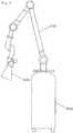
- Fig. 1is a schematic view illustrating a whole of the intake device in this embodiment.
- the "flow straightening member” (0204)is a component arranged inside the suction hood, having a function for introducing the air sucked from the suction port (0205) into the cavity.
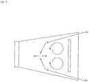
- the flow straightening member in this embodimentis convex toward a fluid flow direction. As illustrated in Fig. 2 , being convex toward a fluid flow direction means being convex toward the exhaust port (0206).
- the flow straightening memberis fixed to the inside of the suction hood by the supporting base (0207).
- the flow straightening memberis completely housed in the inner space of the suction hood in order to solve such a problem.
- Fig. 9is a view enlarging the suction hood part of the intake device in this embodiment.
- the "flow straightening member" (0904) in this embodimentis arranged to be completely housed in the inner space of the suction hood.
Landscapes
- Health & Medical Sciences (AREA)
- Life Sciences & Earth Sciences (AREA)
- Animal Behavior & Ethology (AREA)
- General Health & Medical Sciences (AREA)
- Public Health (AREA)
- Veterinary Medicine (AREA)
- Dentistry (AREA)
- Epidemiology (AREA)
- Ventilation (AREA)
Description
- The present invention relates to an intake device comprising a flow straightening member in an opening part of a suction hood.
- In dental treatment, an extraoral intake device is used for protecting health of patients and dental medical workers and keeping the inside of an examination room clean by sucking at patients' mouth dust or spray which scatters to the outside of a mouth during the examination, such as shavings of teeth or repairing material, saliva, bacterium, blood, rinse water, cleaning agent for tooth surfaces, and so on.
- [Patent Literature 1] Patent Application Publication No.
2012-75705 - However, in the conventional technique, the above dust or spray cannot be completely sucked because the suction force is weak or because distance or positional relationship between a suction hood and a mouth is not appropriate.
JP 2011 122738 A JP 2011 122738 A DE 299 00 106 U1 discloses an inspection hood, in particular for welding fumes and grinding dust, the hood being connected at its connecting end to a rigid or flexible pipeline leading to a fan and, if appropriate, to a separator upstream or downstream of the fan, wherein a truncated cone or a truncated pyramid reduces the funnel opening inside the detection funnel.US 6 308 707 B1 discloses a vacuum equipment used in medical tables' environmental hygiene so as to lessen the possibility of doctors and nursing staffs from contracting infectious diseases.- In order to improve suction force, the present invention provides an intake device comprising a flow straightening member in an opening part of a suction hood.
- Specifically, the present invention provides an intake device having a suction hood provided with a flow straightening member convex toward a fluid flow direction. The flow straightening member is arranged to protrude from the inner space of the suction hood. The protruding part of the flow straightening member is convex toward the opposite side of a fluid flow direction.
- The present invention provides an intake device which can efficiently suck dust or spray scattering widely.
- Embodiments not forming part of the present invention will be described below by using the attached drawings.
- The intake device in this embodiment is provided with a flow straightening member convex toward a fluid flow direction in its suction hood.
- The intake device in this embodiment has a suction hood provided with a flow straightening member, and additionally, may have a main body or an arm and the like.
Fig. 1 is a schematic view illustrating a whole of the intake device in this embodiment. - The "main body" (0101) is provided with a mechanism which generates negative pressure to perform suction. Specifically, a motor starts rotating when turning on power, and a member connected to a rotary shaft of the motor rotates to generate negative pressure inside the main body.
- The "arm" (0102) is a component connected to the main body, having a function for supporting a suction hood which will be explained in detail. As illustrated in
Fig. 1 , the arm is preferably provided with a plurality of joints. By this configuration, the position of the suction hood connected to the tip of the arm can be easily adjusted. - The "suction hood" (0103) is a component connected to the tip of the arm, having a function for catching dust or spray.
Fig. 2 is a view enlarging the suction hood part of the intake device in this embodiment. The dotted line part illustrates the structure inside the suction hood. As illustrated inFig. 2 , in this embodiment, an inner surface of the suction hood is configured to have a megaphone's inner surface shape. By this configuration, the catching space is made larger and dust or spray scattering widely can be sucked efficiently. - The "flow straightening member" (0204) is a component arranged inside the suction hood, having a function for introducing the air sucked from the suction port (0205) into the cavity. The flow straightening member in this embodiment is convex toward a fluid flow direction. As illustrated in
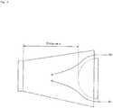
Fig. 2 , being convex toward a fluid flow direction means being convex toward the exhaust port (0206). The flow straightening member is fixed to the inside of the suction hood by the supporting base (0207). Fig. 3 is a schematic view illustrating the flow straightening in the conventional technique. As illustrated inFig. 3 , the flow straightening member in a plate shape as in the conventional technique cannot sufficiently prevent the occurrence of a vortex.Fig. 4 is a schematic view illustrating the flow straightening in the intake device in this embodiment. As illustrated inFig. 4 , in case where the flow straightening member is configured to have a generally partial spherical shape convex toward the exhaust port, the sucked air is introduced along the convex surface. Therefore, it does not generate a vortex and is carried to the exhaust port smoothly. In order to minimize the volume of the catching space where a vortex may occur, the distance x from the end of the flow straightening member to the exhaust port is preferably short.- As the shape of the flow straightening member, other than a generally partial spherical shape, it is also considered to take a generally egg shape as illustrated in
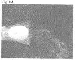
Fig. 5 , or a generally cone shape as illustrated inFig. 6 , or a generally pyramidal shape as illustrated inFig. 7 . In any of the shape, the sucked air is carried to the exhaust port smoothly along the convex surface of the flow straightening member. Fig. 8a to 8d are photos of the intake device sucking smoke.Fig. 8a is a photo in case where the flow straightening member is configured to be planar.Fig. 8b is a photo in case where the flow straightening member is configured to be convex toward the opposite side of a fluid flow direction.Fig. 8c is a photo in case where the flow straightening member is configured to have a generally partial spherical shape convex toward a fluid flow direction.Fig. 8d is a photo in case where the flow straightening member is configured to have a generally egg shape convex toward a fluid flow direction. InFig. 8c and8d , in comparison withFig. 8a and8b , a line of the sucked smoke appears clearly. Therefore, it is shown that the occurrence of a vortex near the exhaust port is prevented and the sucking linear velocity is improved by the flow straightening member configured as in this embodiment.- In the intake device in the
embodiment 1, in case where a part of the flow straightening member is arranged outside the suction hood, the air introduced along the part does not flow to the exhaust port directly and a part of dust or spray scatters to the vicinity. - In the intake device in this embodiment, the flow straightening member is completely housed in the inner space of the suction hood in order to solve such a problem.
- The intake device in this embodiment comprises a main body, an arm, a suction hood, and a flow straightening member. The main body, the arm, and the suction hood are the same as described in the
embodiment 1. The flow straightening member is the same as described in theembodiment 1, except for the following points. Fig. 9 is a view enlarging the suction hood part of the intake device in this embodiment. As illustrated inFig. 9 , the "flow straightening member" (0904) in this embodiment is arranged to be completely housed in the inner space of the suction hood. By this configuration, the air introduced along the convex surface of the flow straightening member wholly flow to the exhaust port and dust or spray can be efficiently sucked.- Embodiment 3 describes the claimed invention.
- The intake device in this embodiment is characterized in that a part of the flow straightening member is arranged to protrude from the inner space of the suction hood and the protruding part is convex toward the opposite side of a fluid flow direction.
- The intake device in this embodiment comprises a main body, an arm, a suction hood, and a flow straightening member. The main body, the arm, and the suction hood are the same as described in the
embodiment 1. The flow straightening member is the same as described in theembodiment 1, except for the following points. Fig. 10 is a view enlarging the suction hood part of the intake device in this embodiment. As illustrated inFig. 10 , the "flow straightening member" (1004) in this embodiment is arranged to protrude from the inner space of the suction hood. The protruding part of the flow straightening member (1008) is configured to be convex toward the opposite side of a fluid flow direction.- In the intake device in this embodiment, for the protruding part of the flow straightening member has a convex shape, the air introduced along the part of the flow straightening member is carried to the inner space of the suction hood smoothly and dust or spray does not scatter to the vicinity. In case where the flow straightening member is configured to have the shape as illustrated in
Fig. 10 , the distance from the end of the flow straightening member to the exhaust port is made short and the occurrence of a vortex can be prevented more efficiently. - The present invention provides an intake device which can efficiently suck dust or spray scattering widely.
Fig. 1 is a schematic view illustrating a whole of the intake device in theembodiment 1;Fig. 2 is a view enlarging the suction hood part of the intake device in theembodiment 1;Fig. 3 is a schematic view illustrating the flow straightening in the conventional technique;Fig. 4 is a schematic view illustrating the flow straightening in the intake device in theembodiment 1;Fig. 5 is a view illustrating an example of the shape of the flow straightening member;Fig. 6 is a view illustrating an example of the shape of the flow straightening member;Fig. 7 is a view illustrating an example of the shape of the flow straightening member;Fig. 8a is a photo of the intake device sucking smoke in case where the flow straightening member is configured to be planar;Fig. 8b is a photo of the intake device sucking smoke in case where the flow straightening member is configured to be convex toward the opposite side of a fluid flow direction;Fig. 8c is a photo of the intake device sucking smoke in case where the flow straightening member is configured to have a generally partial spherical shape convex toward a fluid flow direction;Fig. 8d is a photo of the intake device sucking smoke in case where the flow straightening member is configured to have a generally egg shape convex toward a fluid flow direction;Fig. 9 is a view enlarging the suction hood part of the intake device in the embodiment 2; andFig. 10 is a view enlarging the suction hood part of the intake device in the embodiment 3.- 0101
- main body
- 0102
- arm
- 0103
- suction hood
- 0204
- flow straightening member
- 0205
- suction port
- 0206
- exhaust port
- 0207
- supporting base
- 1008
- protruding part of flow straightening member
Claims (3)
- An intake device having a suction hood (1003) provided with a flow straightening member (1004) convex toward a fluid flow direction, wherein the flow straightening member (1004) is arranged to protrude from the inner space of the suction hood (1003) and the protruding part (1008) of the flow straightening member (1004) is convex toward the opposite side of a fluid flow direction.
- An intake device according to claim 1, wherein the flow straightening member (1004) has one kind of shape selected from a generally egg shape, a generally cone shape, a generally pyramidal shape, and a generally partial spherical shape.
- An intake device according to claim 1 or 2, wherein an inner surface of the suction hood (1003) has a megaphone's inner surface shape.
Applications Claiming Priority (2)
| Application Number | Priority Date | Filing Date | Title |
|---|---|---|---|
| JP2013087134AJP6332841B2 (en) | 2013-04-18 | 2013-04-18 | Intake device |
| PCT/JP2014/061502WO2014171555A1 (en) | 2013-04-18 | 2014-04-17 | Intake device |
Publications (3)
| Publication Number | Publication Date |
|---|---|
| EP2987462A1 EP2987462A1 (en) | 2016-02-24 |
| EP2987462A4 EP2987462A4 (en) | 2017-01-11 |
| EP2987462B1true EP2987462B1 (en) | 2018-06-13 |
Family
ID=51731487
Family Applications (1)
| Application Number | Title | Priority Date | Filing Date |
|---|---|---|---|
| EP14786090.2AActiveEP2987462B1 (en) | 2013-04-18 | 2014-04-17 | Intake device |
Country Status (4)
| Country | Link |
|---|---|
| US (1) | US9888989B2 (en) |
| EP (1) | EP2987462B1 (en) |
| JP (1) | JP6332841B2 (en) |
| WO (1) | WO2014171555A1 (en) |
Families Citing this family (8)
| Publication number | Priority date | Publication date | Assignee | Title |
|---|---|---|---|---|
| TWI517905B (en)* | 2012-09-08 | 2016-01-21 | 西凱渥資訊處理科技公司 | Devices and methods related to paint mist collection during manufacture of radio-frequency modules |
| CN106151107A (en)* | 2016-08-02 | 2016-11-23 | 南通白云环保工程设备有限公司 | A kind of band speed reducer type wind-collecting cover |
| US10829228B2 (en) | 2017-01-17 | 2020-11-10 | Itt Manufacturing Enterprises, Llc | Fluid straightening connection unit |
| USD942617S1 (en) | 2020-01-08 | 2022-02-01 | Mark George Smith | Dental suction attachment |
| ES1251709Y (en)* | 2020-06-05 | 2020-11-16 | Bonnin Bernardo Gabriel Trigo | Protection device |
| US11219500B2 (en)* | 2020-06-08 | 2022-01-11 | Perio Dome Inc | Aerosol reduction systems and methods |
| US20210401557A1 (en)* | 2020-06-24 | 2021-12-30 | Shu-Chuan SHEU | Oral medical assist device |
| US11723760B2 (en)* | 2021-08-06 | 2023-08-15 | Gregory Prior | Aerosol deflecting dental shield and containment device |
Family Cites Families (29)
| Publication number | Priority date | Publication date | Assignee | Title |
|---|---|---|---|---|
| JPS4996752U (en)* | 1972-12-08 | 1974-08-21 | ||
| JPS56109536U (en)* | 1980-01-25 | 1981-08-25 | ||
| USD287402S (en)* | 1983-06-17 | 1986-12-23 | Orsing Ernst L | Nozzle for a suction drainage device for performing surgery in the mouth |
| US4776793A (en)* | 1987-09-17 | 1988-10-11 | Rocca Nina | Dental aspirator |
| USD312872S (en)* | 1987-11-09 | 1990-12-11 | Thomas Mahl | Dental suction head |
| US4865545A (en)* | 1988-07-27 | 1989-09-12 | Rocca Nina | Dental aspirator |
| JPH0725537Y2 (en)* | 1989-04-03 | 1995-06-07 | 大阪瓦斯株式会社 | Household range hood |
| JPH0938112A (en)* | 1995-07-26 | 1997-02-10 | Tokyo Giken:Kk | Dental suction hood device |
| NO971697L (en)* | 1997-04-14 | 1998-10-15 | Vidar Wiik | Device for gas and particulate removal in connection with welding / cutting |
| US6186783B1 (en)* | 1997-10-17 | 2001-02-13 | Dentsply Research & Development Corp. | Evacuation hand piece for use during dental procedures |
| DE29900106U1 (en)* | 1999-01-07 | 1999-04-08 | Lauer, Oliver, Dipl.-Ing., 54295 Trier | Detection hood, especially for welding fumes and grinding dusts |
| US6308707B1 (en) | 1999-02-10 | 2001-10-30 | Li-Chow Lu | Vacuum equipment for medical tables |
| JP2000256980A (en)* | 1999-03-11 | 2000-09-19 | Sumiju Ahlstrom Kk | Pulp-treating apparatus |
| DE60035213T2 (en)* | 1999-11-05 | 2007-09-27 | Delaware Capital Formation, Inc., Wilmington | FLUE EXTRACTION DEVICE AND ARRANGEMENT |
| JP3600224B2 (en) | 2002-07-03 | 2004-12-15 | 株式会社長田中央研究所 | Dental respiratory protection device |
| DE10347829A1 (en)* | 2003-10-10 | 2005-05-25 | Coltène/Whaledent GmbH + Co. KG | Two component suction |
| US6776710B1 (en)* | 2003-10-24 | 2004-08-17 | Unico, Inc. | Vent structure for slotted outlet with uniform velocity profile |
| US20110262880A1 (en)* | 2004-04-22 | 2011-10-27 | Mccary Charles | Method for filtering and treating dental solid waste |
| US7238023B1 (en)* | 2004-12-14 | 2007-07-03 | Enos Denise A | Saliva ejector or eductor |
| US7625207B2 (en)* | 2006-12-15 | 2009-12-01 | Kimberly-Clark Worldwide, Inc. | Yankauer suction device with sleeve and wiper |
| US8012141B2 (en)* | 2007-03-29 | 2011-09-06 | Wright Clifford A | Suction wand |
| US8460417B2 (en)* | 2008-11-11 | 2013-06-11 | Great Lakes Air Systems, Inc. | Portable air filtration system |
| JP5379661B2 (en)* | 2009-12-08 | 2013-12-25 | 株式会社大気社 | Exhaust device with auxiliary jet port and exhaust unit using the exhaust device with auxiliary jet port |
| US8398398B1 (en)* | 2010-02-25 | 2013-03-19 | William L. Barham | Foam pad used with tubular member to vacuum fluids from an oral cavity |
| SE535187C2 (en)* | 2010-09-10 | 2012-05-15 | Fumex Ab | Joint construction, ventilation arm and ventilation system |
| JP5627095B2 (en) | 2010-10-01 | 2014-11-19 | 株式会社東京技研 | Dental extraoral vacuum device |
| JP2012112311A (en)* | 2010-11-25 | 2012-06-14 | Toyota Boshoku Corp | Air filter and air cleaner |
| JP4886095B1 (en) | 2011-11-01 | 2012-02-29 | 有海 宮脇 | Water cone body with built-in rectifier |
| US9872705B2 (en)* | 2013-10-07 | 2018-01-23 | Regentis Biomaterials Ltd. | Treatment of cavities in a human body |
- 2013
- 2013-04-18JPJP2013087134Apatent/JP6332841B2/enactiveActive
- 2014
- 2014-04-17WOPCT/JP2014/061502patent/WO2014171555A1/enactiveApplication Filing
- 2014-04-17USUS14/779,745patent/US9888989B2/enactiveActive
- 2014-04-17EPEP14786090.2Apatent/EP2987462B1/enactiveActive
Non-Patent Citations (1)
| Title |
|---|
| None* |
Also Published As
| Publication number | Publication date |
|---|---|
| WO2014171555A1 (en) | 2014-10-23 |
| US9888989B2 (en) | 2018-02-13 |
| US20160100922A1 (en) | 2016-04-14 |
| JP6332841B2 (en) | 2018-05-30 |
| EP2987462A1 (en) | 2016-02-24 |
| JP2014210003A (en) | 2014-11-13 |
| EP2987462A4 (en) | 2017-01-11 |
Similar Documents
| Publication | Publication Date | Title |
|---|---|---|
| EP2987462B1 (en) | Intake device | |
| JP5961328B1 (en) | Intraoral dental suction and separation system | |
| US20210338396A1 (en) | Manifold for attachment to a medical or dental chair and use thereof to remove aerosols emitted form a patient during a clinical procedure | |
| WO2010117485A2 (en) | Dental evacuation tool | |
| US20110179597A1 (en) | Debris collecting apparatus and methods of making and using the same | |
| US20210369430A1 (en) | Hands free, articulable dental suction device | |
| WO2021220316A1 (en) | Dental suction device | |
| JP2014100177A (en) | Simple suction tray with hood for work outside dental cavity | |
| JP2017113328A (en) | Suction path pipe with dental mirror | |
| WO2022120495A1 (en) | Intra-oral appliance | |
| JP2009045644A (en) | Suction nozzle | |
| EP2964284B1 (en) | Collection member for a nasal aspirator and nasal aspirator | |
| CN212728881U (en) | Protective mask for dental operation | |
| US20220000595A1 (en) | Systems and methods for an evacuator adaptor | |
| US20230380946A1 (en) | Aerosol deflecting dental shield and containment device | |
| CN219614084U (en) | Saliva sucking device for strong suction | |
| CN221904153U (en) | Bent straw aid for dental operation | |
| CN221712261U (en) | A dental splash protection device | |
| CN220175252U (en) | Sand blasting protection device of sand blasting machine | |
| CN210962407U (en) | Strong straw protection casing | |
| JP6320043B2 (en) | Suction device, suction tube for suction device, and cap for suction device | |
| JP7444451B2 (en) | Protector base plate, protector, and protector mounting structure | |
| EP4173591A1 (en) | Protective shield for a dental instrument | |
| CN212913450U (en) | Strong negative pressure saliva suction head for oral diagnosis and treatment | |
| JPH11169388A (en) | Medical protect attachment |
Legal Events
| Date | Code | Title | Description |
|---|---|---|---|
| PUAI | Public reference made under article 153(3) epc to a published international application that has entered the european phase | Free format text:ORIGINAL CODE: 0009012 | |
| 17P | Request for examination filed | Effective date:20151118 | |
| AK | Designated contracting states | Kind code of ref document:A1 Designated state(s):AL AT BE BG CH CY CZ DE DK EE ES FI FR GB GR HR HU IE IS IT LI LT LU LV MC MK MT NL NO PL PT RO RS SE SI SK SM TR | |
| AX | Request for extension of the european patent | Extension state:BA ME | |
| DAX | Request for extension of the european patent (deleted) | ||
| A4 | Supplementary search report drawn up and despatched | Effective date:20161209 | |
| RIC1 | Information provided on ipc code assigned before grant | Ipc:B08B 15/04 20060101ALI20161205BHEP Ipc:A61C 17/06 20060101ALI20161205BHEP Ipc:A61C 17/08 20060101AFI20161205BHEP Ipc:A61C 19/00 20060101ALI20161205BHEP Ipc:A61G 15/14 20060101ALI20161205BHEP | |
| GRAP | Despatch of communication of intention to grant a patent | Free format text:ORIGINAL CODE: EPIDOSNIGR1 | |
| STAA | Information on the status of an ep patent application or granted ep patent | Free format text:STATUS: GRANT OF PATENT IS INTENDED | |
| INTG | Intention to grant announced | Effective date:20180115 | |
| GRAS | Grant fee paid | Free format text:ORIGINAL CODE: EPIDOSNIGR3 | |
| GRAA | (expected) grant | Free format text:ORIGINAL CODE: 0009210 | |
| STAA | Information on the status of an ep patent application or granted ep patent | Free format text:STATUS: THE PATENT HAS BEEN GRANTED | |
| AK | Designated contracting states | Kind code of ref document:B1 Designated state(s):AL AT BE BG CH CY CZ DE DK EE ES FI FR GB GR HR HU IE IS IT LI LT LU LV MC MK MT NL NO PL PT RO RS SE SI SK SM TR | |
| REG | Reference to a national code | Ref country code:GB Ref legal event code:FG4D | |
| REG | Reference to a national code | Ref country code:CH Ref legal event code:EP Ref country code:AT Ref legal event code:REF Ref document number:1007684 Country of ref document:AT Kind code of ref document:T Effective date:20180615 | |
| REG | Reference to a national code | Ref country code:IE Ref legal event code:FG4D | |
| REG | Reference to a national code | Ref country code:DE Ref legal event code:R096 Ref document number:602014027050 Country of ref document:DE | |
| REG | Reference to a national code | Ref country code:CH Ref legal event code:NV Representative=s name:RENTSCH PARTNER AG, CH | |
| REG | Reference to a national code | Ref country code:NL Ref legal event code:MP Effective date:20180613 | |
| REG | Reference to a national code | Ref country code:LT Ref legal event code:MG4D | |
| PG25 | Lapsed in a contracting state [announced via postgrant information from national office to epo] | Ref country code:LT Free format text:LAPSE BECAUSE OF FAILURE TO SUBMIT A TRANSLATION OF THE DESCRIPTION OR TO PAY THE FEE WITHIN THE PRESCRIBED TIME-LIMIT Effective date:20180613 Ref country code:ES Free format text:LAPSE BECAUSE OF FAILURE TO SUBMIT A TRANSLATION OF THE DESCRIPTION OR TO PAY THE FEE WITHIN THE PRESCRIBED TIME-LIMIT Effective date:20180613 Ref country code:NO Free format text:LAPSE BECAUSE OF FAILURE TO SUBMIT A TRANSLATION OF THE DESCRIPTION OR TO PAY THE FEE WITHIN THE PRESCRIBED TIME-LIMIT Effective date:20180913 Ref country code:CY Free format text:LAPSE BECAUSE OF FAILURE TO SUBMIT A TRANSLATION OF THE DESCRIPTION OR TO PAY THE FEE WITHIN THE PRESCRIBED TIME-LIMIT Effective date:20180613 Ref country code:SE Free format text:LAPSE BECAUSE OF FAILURE TO SUBMIT A TRANSLATION OF THE DESCRIPTION OR TO PAY THE FEE WITHIN THE PRESCRIBED TIME-LIMIT Effective date:20180613 Ref country code:BG Free format text:LAPSE BECAUSE OF FAILURE TO SUBMIT A TRANSLATION OF THE DESCRIPTION OR TO PAY THE FEE WITHIN THE PRESCRIBED TIME-LIMIT Effective date:20180913 Ref country code:FI Free format text:LAPSE BECAUSE OF FAILURE TO SUBMIT A TRANSLATION OF THE DESCRIPTION OR TO PAY THE FEE WITHIN THE PRESCRIBED TIME-LIMIT Effective date:20180613 | |
| PG25 | Lapsed in a contracting state [announced via postgrant information from national office to epo] | Ref country code:GR Free format text:LAPSE BECAUSE OF FAILURE TO SUBMIT A TRANSLATION OF THE DESCRIPTION OR TO PAY THE FEE WITHIN THE PRESCRIBED TIME-LIMIT Effective date:20180914 Ref country code:RS Free format text:LAPSE BECAUSE OF FAILURE TO SUBMIT A TRANSLATION OF THE DESCRIPTION OR TO PAY THE FEE WITHIN THE PRESCRIBED TIME-LIMIT Effective date:20180613 Ref country code:LV Free format text:LAPSE BECAUSE OF FAILURE TO SUBMIT A TRANSLATION OF THE DESCRIPTION OR TO PAY THE FEE WITHIN THE PRESCRIBED TIME-LIMIT Effective date:20180613 Ref country code:HR Free format text:LAPSE BECAUSE OF FAILURE TO SUBMIT A TRANSLATION OF THE DESCRIPTION OR TO PAY THE FEE WITHIN THE PRESCRIBED TIME-LIMIT Effective date:20180613 | |
| PG25 | Lapsed in a contracting state [announced via postgrant information from national office to epo] | Ref country code:NL Free format text:LAPSE BECAUSE OF FAILURE TO SUBMIT A TRANSLATION OF THE DESCRIPTION OR TO PAY THE FEE WITHIN THE PRESCRIBED TIME-LIMIT Effective date:20180613 | |
| PG25 | Lapsed in a contracting state [announced via postgrant information from national office to epo] | Ref country code:CZ Free format text:LAPSE BECAUSE OF FAILURE TO SUBMIT A TRANSLATION OF THE DESCRIPTION OR TO PAY THE FEE WITHIN THE PRESCRIBED TIME-LIMIT Effective date:20180613 Ref country code:SK Free format text:LAPSE BECAUSE OF FAILURE TO SUBMIT A TRANSLATION OF THE DESCRIPTION OR TO PAY THE FEE WITHIN THE PRESCRIBED TIME-LIMIT Effective date:20180613 Ref country code:IS Free format text:LAPSE BECAUSE OF FAILURE TO SUBMIT A TRANSLATION OF THE DESCRIPTION OR TO PAY THE FEE WITHIN THE PRESCRIBED TIME-LIMIT Effective date:20181013 Ref country code:EE Free format text:LAPSE BECAUSE OF FAILURE TO SUBMIT A TRANSLATION OF THE DESCRIPTION OR TO PAY THE FEE WITHIN THE PRESCRIBED TIME-LIMIT Effective date:20180613 Ref country code:PL Free format text:LAPSE BECAUSE OF FAILURE TO SUBMIT A TRANSLATION OF THE DESCRIPTION OR TO PAY THE FEE WITHIN THE PRESCRIBED TIME-LIMIT Effective date:20180613 Ref country code:RO Free format text:LAPSE BECAUSE OF FAILURE TO SUBMIT A TRANSLATION OF THE DESCRIPTION OR TO PAY THE FEE WITHIN THE PRESCRIBED TIME-LIMIT Effective date:20180613 | |
| PG25 | Lapsed in a contracting state [announced via postgrant information from national office to epo] | Ref country code:SM Free format text:LAPSE BECAUSE OF FAILURE TO SUBMIT A TRANSLATION OF THE DESCRIPTION OR TO PAY THE FEE WITHIN THE PRESCRIBED TIME-LIMIT Effective date:20180613 Ref country code:IT Free format text:LAPSE BECAUSE OF FAILURE TO SUBMIT A TRANSLATION OF THE DESCRIPTION OR TO PAY THE FEE WITHIN THE PRESCRIBED TIME-LIMIT Effective date:20180613 | |
| REG | Reference to a national code | Ref country code:DE Ref legal event code:R097 Ref document number:602014027050 Country of ref document:DE | |
| PLBE | No opposition filed within time limit | Free format text:ORIGINAL CODE: 0009261 | |
| STAA | Information on the status of an ep patent application or granted ep patent | Free format text:STATUS: NO OPPOSITION FILED WITHIN TIME LIMIT | |
| 26N | No opposition filed | Effective date:20190314 | |
| PG25 | Lapsed in a contracting state [announced via postgrant information from national office to epo] | Ref country code:DK Free format text:LAPSE BECAUSE OF FAILURE TO SUBMIT A TRANSLATION OF THE DESCRIPTION OR TO PAY THE FEE WITHIN THE PRESCRIBED TIME-LIMIT Effective date:20180613 Ref country code:SI Free format text:LAPSE BECAUSE OF FAILURE TO SUBMIT A TRANSLATION OF THE DESCRIPTION OR TO PAY THE FEE WITHIN THE PRESCRIBED TIME-LIMIT Effective date:20180613 | |
| PG25 | Lapsed in a contracting state [announced via postgrant information from national office to epo] | Ref country code:AL Free format text:LAPSE BECAUSE OF FAILURE TO SUBMIT A TRANSLATION OF THE DESCRIPTION OR TO PAY THE FEE WITHIN THE PRESCRIBED TIME-LIMIT Effective date:20180613 | |
| REG | Reference to a national code | Ref country code:BE Ref legal event code:MM Effective date:20190430 | |
| PG25 | Lapsed in a contracting state [announced via postgrant information from national office to epo] | Ref country code:MC Free format text:LAPSE BECAUSE OF FAILURE TO SUBMIT A TRANSLATION OF THE DESCRIPTION OR TO PAY THE FEE WITHIN THE PRESCRIBED TIME-LIMIT Effective date:20180613 Ref country code:LU Free format text:LAPSE BECAUSE OF NON-PAYMENT OF DUE FEES Effective date:20190417 | |
| PG25 | Lapsed in a contracting state [announced via postgrant information from national office to epo] | Ref country code:BE Free format text:LAPSE BECAUSE OF NON-PAYMENT OF DUE FEES Effective date:20190430 | |
| PG25 | Lapsed in a contracting state [announced via postgrant information from national office to epo] | Ref country code:TR Free format text:LAPSE BECAUSE OF FAILURE TO SUBMIT A TRANSLATION OF THE DESCRIPTION OR TO PAY THE FEE WITHIN THE PRESCRIBED TIME-LIMIT Effective date:20180613 | |
| PG25 | Lapsed in a contracting state [announced via postgrant information from national office to epo] | Ref country code:IE Free format text:LAPSE BECAUSE OF NON-PAYMENT OF DUE FEES Effective date:20190417 | |
| REG | Reference to a national code | Ref country code:AT Ref legal event code:UEP Ref document number:1007684 Country of ref document:AT Kind code of ref document:T Effective date:20180613 | |
| PG25 | Lapsed in a contracting state [announced via postgrant information from national office to epo] | Ref country code:PT Free format text:LAPSE BECAUSE OF FAILURE TO SUBMIT A TRANSLATION OF THE DESCRIPTION OR TO PAY THE FEE WITHIN THE PRESCRIBED TIME-LIMIT Effective date:20181015 | |
| PG25 | Lapsed in a contracting state [announced via postgrant information from national office to epo] | Ref country code:HU Free format text:LAPSE BECAUSE OF FAILURE TO SUBMIT A TRANSLATION OF THE DESCRIPTION OR TO PAY THE FEE WITHIN THE PRESCRIBED TIME-LIMIT; INVALID AB INITIO Effective date:20140417 Ref country code:MT Free format text:LAPSE BECAUSE OF FAILURE TO SUBMIT A TRANSLATION OF THE DESCRIPTION OR TO PAY THE FEE WITHIN THE PRESCRIBED TIME-LIMIT Effective date:20180613 | |
| PG25 | Lapsed in a contracting state [announced via postgrant information from national office to epo] | Ref country code:MK Free format text:LAPSE BECAUSE OF FAILURE TO SUBMIT A TRANSLATION OF THE DESCRIPTION OR TO PAY THE FEE WITHIN THE PRESCRIBED TIME-LIMIT Effective date:20180613 | |
| P01 | Opt-out of the competence of the unified patent court (upc) registered | Effective date:20230529 | |
| PGFP | Annual fee paid to national office [announced via postgrant information from national office to epo] | Ref country code:GB Payment date:20240423 Year of fee payment:11 | |
| PGFP | Annual fee paid to national office [announced via postgrant information from national office to epo] | Ref country code:DE Payment date:20240429 Year of fee payment:11 | |
| PGFP | Annual fee paid to national office [announced via postgrant information from national office to epo] | Ref country code:CH Payment date:20240501 Year of fee payment:11 | |
| PGFP | Annual fee paid to national office [announced via postgrant information from national office to epo] | Ref country code:AT Payment date:20240417 Year of fee payment:11 | |
| PGFP | Annual fee paid to national office [announced via postgrant information from national office to epo] | Ref country code:FR Payment date:20240419 Year of fee payment:11 |