EP2987307B1 - Techniques enabling use of a wi-fi direct services (wfds) application services platform (asp) for layer 2 services - Google Patents
Techniques enabling use of a wi-fi direct services (wfds) application services platform (asp) for layer 2 servicesDownload PDFInfo
- Publication number
- EP2987307B1 EP2987307B1EP13882147.5AEP13882147AEP2987307B1EP 2987307 B1EP2987307 B1EP 2987307B1EP 13882147 AEP13882147 AEP 13882147AEP 2987307 B1EP2987307 B1EP 2987307B1
- Authority
- EP
- European Patent Office
- Prior art keywords
- asp
- wfds
- session
- services
- service
- Prior art date
- Legal status (The legal status is an assumption and is not a legal conclusion. Google has not performed a legal analysis and makes no representation as to the accuracy of the status listed.)
- Active
Links
Images


Classifications
- H—ELECTRICITY
- H04—ELECTRIC COMMUNICATION TECHNIQUE
- H04W—WIRELESS COMMUNICATION NETWORKS
- H04W8/00—Network data management
- H04W8/005—Discovery of network devices, e.g. terminals
- H—ELECTRICITY
- H04—ELECTRIC COMMUNICATION TECHNIQUE
- H04L—TRANSMISSION OF DIGITAL INFORMATION, e.g. TELEGRAPHIC COMMUNICATION
- H04L61/00—Network arrangements, protocols or services for addressing or naming
- H—ELECTRICITY
- H04—ELECTRIC COMMUNICATION TECHNIQUE
- H04W—WIRELESS COMMUNICATION NETWORKS
- H04W76/00—Connection management
- H04W76/10—Connection setup
- H04W76/14—Direct-mode setup
- H—ELECTRICITY
- H04—ELECTRIC COMMUNICATION TECHNIQUE
- H04W—WIRELESS COMMUNICATION NETWORKS
- H04W80/00—Wireless network protocols or protocol adaptations to wireless operation
- H04W80/02—Data link layer protocols
- H—ELECTRICITY
- H04—ELECTRIC COMMUNICATION TECHNIQUE
- H04W—WIRELESS COMMUNICATION NETWORKS
- H04W80/00—Wireless network protocols or protocol adaptations to wireless operation
- H04W80/04—Network layer protocols, e.g. mobile IP [Internet Protocol]
- H—ELECTRICITY
- H04—ELECTRIC COMMUNICATION TECHNIQUE
- H04W—WIRELESS COMMUNICATION NETWORKS
- H04W84/00—Network topologies
- H04W84/02—Hierarchically pre-organised networks, e.g. paging networks, cellular networks, WLAN [Wireless Local Area Network] or WLL [Wireless Local Loop]
- H04W84/10—Small scale networks; Flat hierarchical networks
- H04W84/12—WLAN [Wireless Local Area Networks]
Definitions
- Wi-Fi Serial Buswhich enables support of USB traffic over Wi-Fi links and allows a WSB host to connect to Wi-Fi enabled USB devices/functions (WSB peripherals) wirelessly and to legacy USB devices/functions via a Wi-Fi enabled USB hub (WSB Hub).
- WBWi-Fi Serial Bus
- Wi-Fi Directprovides peer-to-peer connectivity to allow users to connect their devices in an easy and convenient manner to share, show, print, and synchronize content.
- Wi-Fi Directonly provides link-layer connectivity. Wi-Fi Direct is not enough to enable interoperability between services/applications from multiple vendors. Users have inconsistent experiences due to lack of services interoperability and complexity of P2P topology.
- US 2013/034082 A1discloses computer-implemented methods, systems, computing devices, and computer-readable media for opportunistically transitioning service flows of mobile devices between being direct and indirect.
- a proximity between first and second mobile devices that are in wireless communication with each othermay be monitored.
- a selective transition of a service flow between the first and second mobile devices from being indirect through the radio network access node using a first radio access technology (RAT) to being direct using a second RATmay be facilitated, e.g., responsive to a determination that a first criterion has been met.
- a selective transition of the service flow from being direct using the second RAT to being indirect using the first RATmay be facilitated, e.g., responsive to a determination that a second criterion has been met.
- RATradio access technology
- Some embodimentsare directed to a wireless device according to claim 1, a method according to claim 6 and a computer-readable storage medium according to claim 10.
- references to "one embodiment,” “an embodiment,” “example embodiment,” 'Various embodiments,” etc.,indicate that the embodiment(s) of the invention so described may include a particular feature, structure, or characteristic, but not every embodiment necessarily includes the particular feature, structure, or characteristic. Further, repeated use of the phrase “in one embodiment” does not necessarily refer to the same embodiment, although it may.
- Some embodimentsmay be used in conjunction with devices and/or networks operating in accordance with existing Wireless-Gigabit-Alliance (WGA) specifications (Wireless Gigabit Alliance, Inc WiGig MAC and PHY Specification Version 1.1, April 2011, Final specification) and/or future versions and/or derivatives thereof, devices and/or networks operating in accordance with existing IEEE 802.11 standards (IEEE 802.11-2012, IEEE Standard for Information technology-Telecommunications and information exchange between systems Local and metropolitan area networks--Specific requirements Part 11: Wireless LAN Medium Access Control (MAC) and Physical Layer (PHY) Specifications, March 29, 2012; IEEE802.11 task group ac (TGac) ("IEEE802.11-09/0308r12 - TGac Channel Model Addendum Document"); IEEE 802.11 task group ad (TGad) (IEEE P802.11ad Standard for Information Technology - Telecommunications and Information Exchange Between Systems - Local and Metropolitan Area Networks - Specific Requirements - Part 11: Wireless LAN Medium Access Control (
- WFAformed the Wi-Fi Direct Services (WFDS) task group (TG).
- WFDSis tasked with defining a common set of application programming interfaces (APIs) and protocols enabling service interoperability.
- FIG. 1shown generally as 100, depicts the architecture of the WFDS specification.
- the ASP coordination protocol (ASP-CP)is assumed to run over IP
- ASPApplication Service Platform
- ASPis a logical entity that implements the common functions needed by application services such as play, send, display and print.
- different protocol elementsare defined to realize device discovery, service discovery, P2P connection management and session management.
- the ASP coordination protocol(ASP-CP) is the name given to the protocol that allows two peer ASP entities to manage ASP-sessions.
- FIG. 1describes where the ASP-CP lies in the WFDS architecture.
- the WFDS specificationdefines the use of the ASP-CP over IP only. Essentially, this requirement imposes that all devices compliant with the WFDS specification must be capable of supporting an IP stack and associated management functions. While this might not be considered a difficult requirement to meet for devices such as phones, laptops, TV sets, to name a few, it does pose a challenge for a range of new device categories characterized by: High date rates: for interfaces that operate at very high bit rates (e.g., > 3Gbps in 60 GHz), generation and processing of IP packets could become a bottleneck in terms of efficiency and latency.
- Type of servicescertain services do not inherently need or use IP for their operation with cables. Examples include USB, HDMI and DisplayPort (DP). Therefore, as these protocols become wireless, reusing the same architecture which does not rely on IP is a suitable approach.
- Examples hereinprovide apparatus, systems and methods that would allow the ASP-CP and services to operate directly over the MAC (i.e., without using IP).
- IPi.e., without using IP
- Traffic identificationeach service and WFDS messages need to be uniquely identified so that packets can be routed to the proper process. Therefore, packets transferred between the MAC and upper layers need to identify the traffic type.
- Scalabilitythe methods should be scalable so that they can be used not only for services presently defined, but also for future services.
- Service isolationdue to aspects such as security, service isolation should be an important goal to be achieved. This refers to the capability to isolate one service from another, so that security risks can be minimized.
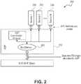
- Example method 1is shown in FIG. 2 , shown generally as 200.
- the ASP 210is responsible for mux/demux 210 of ASP traffic as well as traffic belonging to any service 230, 240 and 250 operating using the ASP.
- One Ethertypeis shared across ASP and services and may support service isolation.
- the ASPis responsible for tagging (e.g., through service identifiers) packets belonging to each service 230, 240 and 250 and ASP 210 in a uniquely identified manner. As a result, packets can be routed to the appropriate end point, whether that is a specific service or the ASP protocol itself.
- EtherTypeis a two-octet field in an Ethernet frame. It is used to indicate which protocol is encapsulated in the payload of an Ethernet Frame. Every service 230, 240 and 250 using the ASP 210 and the ASP protocol itself (see FIG. 1 ) would use the same Ethertype for transmitting to and receiving from the MAC.
- This architecturecan provide for service isolation and scalability.
- Service isolationis supported given that the ASP can manage the identification of the various services 230, 240 and 250 in a dynamic manner. Such dynamicity would increase the level of security. Moreover, new services can be added over time without changes to the architecture, which makes it scalable.
- this methodrequires that a service seeker and a service advertiser exchange service identifiers before transmitting or receiving service data. This is needed so that packets are routed to the correct end point upon reception.
- Method 1increases the complexity of the ASP 210 and makes the delivery of a service dependent on the ASP 210.
- Method 2proposes a decentralized architecture, whereby each service interacts directly with the bottom MAC layer. This is depicted in FIG. 3 .
- an ASP 310 and each servicehave a well-known Ethertype.
- the number of Ethertypesmay be proportional to the number of services and, in an example herein, does not support service isolation.
- Method 2provides stronger support for scalability since service delivery does not rely solely on the ASP. Each service can be independently enabled over the MAC. With respect to service isolation, method 2 does not provide the same level of isolation as method 1, since the Ethertypes are well-known identifications which allows devices to attempt to access/use a service before obtaining the proper authorization from the ASP.
- Method 3shown in FIG. 4 , generally as 400i, improves the service isolation of method 2 by having the ASP 410 dynamically assign the Ethertype used by each service. This may support service isolation. Specifically, the ASP 410 manages a pool of Ethertypes. Once a service becomes in use, the ASP assigns an Ethertype to that particular service 420, 430 and 440. Over the lifetime of a service, it can use different Ethertypes assigned by the ASP.
- Method 3relies on the fact that the ASP 410 manages a pool of Ethertypes and dynamically assigns them to services 420, 430 and 440.
- Method 4is an alternative approach shown in FIG. 5 at 500 that does not require formal allocation of Ethertypes (which is done through the IEEE) is by defining a frame structure that allows the ASP 510 to configure a Service ID for each service 520, 530 and 540 within the frame itself.
- one Ethertypeis allocated for the ASP 510.
- the servicescan either use the same Ethertype as ASP 510 or use a separate Ethertype that can be used by all services 520, 530 and 540. In either case, means are necessary to uniquely identify the service so that packets can be routed to the appropriate service.
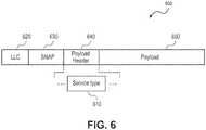
- examples hereindefine a new Service type field 610 that is part of the payload 650 of the frame as shown in FIG. 6 .
- the Payload Header field 640signals the specific service. LLC field and SNAP field are shown as 620 and 630 respectively.
- the payload 650carries data associated with the service.
- the ASP 510would dynamically configure values of Service types to be used by the various services. Once a Service type value is assigned, all the packets belonging to that service use the assigned Service type value.
- the ASP 510can dynamically change the Service type value used by a service. This provides for enhanced security and service isolation.
- the length of the Service type field 610depends on how many services are supported, but can be as short as one octet.
- a packet using the "Services" Ethertypecan be delivered either to all services (and each service would then drop the packet if it does not match the intended Service type) or to a mux/demux function that would do the forwarding to the correct service.
- ASPbecomes a layer that sits above the MAC and below the Service on the data path.
- Wi-Fi Serial Buswhich enables support of USB traffic over Wi-Fi links and allows a WSB host to connect to Wi-Fi enabled USB devices/functions (WSB peripherals) wirelessly and to legacy USB devices/functions via a Wi-Fi enabled USB hub (WSB Hub).
- WSBdefines two modes of operation: Native mode, in which the WSB directly interfaces with the MAC; and the IP-mode, in which the WSB traffic is encapsulated as IP-traffic before being sent to the MAC.
- WSBrelies on Wi-Fi Direct (P2P technology) as an enabling technology for discovery of devices that are WSB capable.
- P2P technologyWi-Fi Direct
- Wi-Fi Direct Servicesis a technology that defines an interoperability framework for service discovery and session management for services that use Wi-Fi Direct.
- WFDS as definedis not applicable to WSB for two main reasons:
- Embodiments hereinaddress the connection and service sessions that are limited to IP sessions by extending the definition of session in WFDS to include non-IP sessions as well.
- Embodiments hereinextend the definition of connection and session in WFDS framework to include non-IP sessions.
- WFDSdefines Application Services Platform (ASP) as a logical entity which is, among other things, responsible for session management for different services. However, the ASP session itself and the application services sessions are established over TCP/IP connections.
- ASPApplication Services Platform
- FIG. 7shown generally as 700, illustrates an embodiment of the procedure for a Layer 2 service establishment between Device A, 720 and Device B 760 with an embodiment of the direction commands and responses illustrated therebetween.
- Device A 720is shown as service advertiser 705 including application 710, service 715 and ASP 725.
- Device B 760is illustrated as service seeker 755 with ASP 740, service 745 and application 750.
- seeker 755 and advertiser 705may be part of a P2P group.
- 735illustrates a layer 2 channel establishment.
- the ASP coordination protocol defined in WFDSconsists of commands and responses (either ACK or NACK) that are sent in form of a single UDP datagram.
- each of these commandsare sent as ASP Session Action frame, an IEEE 802.11 Action Frame.
- the retry mechanisms associated with 802.11 Action Frameapply to ASP coordination protocol.
- Table 2 belowprovides an embodiment of a general format of ASP Session Action Frame.
- the format of ASP Session Action frameis defined as:
- a Layer 2 sessionis established as a "logical channel" carrying the data related to the specific service between the seeker 755 and the advertiser 705.
- This "logical channel”may be identified by different parameters, specifically related to Layer 2; one example may be the parameters in the TSPEC element (defined in IEEE 802.11 standard).
- SESSION_PARAMETERS⁇ Format of SESSION_PARAMETERS message is shown below.
- session_mac 6Variable MAC address used in combination with the session_id to uniquely identify an ASP-Session.
- session_id 4Variable ID used in combination with session_mac to uniquely identify an ASP-Session. This value is received/transmitted in a previous REQUEST_SESSION message L2 logical channel Parameters, e.g., TSPEC element 52 in case of TSPEC element.
- TSPEC elementas defined in IEEE 802.11 or other parameters.
- an embodimentdefines two new ASP Methods and an ASP Event to bind and release the Level 2 logical channel to the layer 2 service and to carry the information regarding the status of the logical channel:
- FIG. 8is a diagram of an implementation 800 that may be included in a wireless devices, which may be a STA and/or an access point or Wi-Fi enabled devices that may utilize the examples shown herein.
- Device 800may perform techniques, as described herein, such as techniques enabling the application services platform coordination protocol (ASP-CP) and services to operate directly over the MAC and such as techniques for using a WI-FI Direct Services (WFDS) Application Services Platform (ASP) for Layer 2 services by extending a definition of a session in WFDS to include non-IP sessions as well.
- ASP-CPapplication services platform coordination protocol
- WFDSWI-FI Direct Services
- ASPApplication Services Platform
- implementation 800may include an antenna module 802, a transceiver module 804, and a host module 806. These elements may be implemented in hardware, software, or any combination thereof.
- Antenna module 802provides for the exchange of wireless signals with remote devices. Moreover, antenna module 802 may transmit wireless signals through one or more directional radiation patterns. Thus, antenna module 802 may include multiple antennas and/or multiple radiating elements (e.g., phased-array radiating elements).
- Transceiver module 804provides an interface between antenna module 802 and host module 806. For instance, transmitter portion 808 within transceiver module 804 receives symbols from host module 806 and generates corresponding signals for wireless transmission by antenna module 802. This may involve operations, such as modulation, amplification, and/or filtering. However, other operations may be employed.
- receiver portion 810 within transceiver module 804obtains signals received by antenna module 802 and generates corresponding symbols.
- receiver portion 810provides symbols to host module 806. This generation of symbols may involve operations, including (but not limited to) demodulation, amplification, and/or filtering.
- the symbols exchanged between host module 806 and transceiver module 804may form messages or information associated with one or more protocols, and/or one or more user applications.
- host module 806may perform operations corresponding to such protocol(s) and/or user application(s).
- exemplary protocolsinclude various media access, network, transport and/or session layer protocols.
- Exemplary user applicationsinclude telephony, messaging, e-mail, web browsing, content (e.g., video and audio) distribution/reception, and so forth.
- host module 806may exchange control information with transceiver module 804.
- This control informationmay pertain to the operation and status of transceiver module 804.
- this control informationmay include directives that host module 806 sends to transceiver module 804.
- directivesmay establish operating parameters/characteristics for transceiver module 804.
- this control informationmay include data (e.g., operational status information) that host module 806 receives from transceiver module 204.
- ASP-CPapplication services platform coordination protocol
- WFDSWI-FI Direct Services
- ASPApplication Services Platform
- transmitter portion 808generates signals from symbols
- receiver portion 810generates symbols from received signals.
- transmitter portion 808 and receiver portion 810may each include various components, such as modulators, demodulators, amplifiers, filters, buffers, upconverters, and/or downconveters.
- Such componentsmay be implemented in hardware (e.g., electronics), software, or any combination thereof.
- the techniques described hereinmay be embodied in a computer-readable medium for configuring a computing system to execute the method.
- the computer readable mediamay include, for example and without limitation, any number of the following: magnetic storage media including disk and tape storage media; optical storage media such as compact disk media (e.g., CD-ROM, CD-R, etc.) and digital video disk storage media; holographic memory; nonvolatile memory storage media including semiconductor-based memory units such as FLASH memory, EEPROM, EPROM, ROM; ferromagnetic digital memories; volatile storage media including registers, buffers or caches, main memory, RAM, etc.; and data transmission media including permanent and intermittent computer networks, point-to-point telecommunication equipment, carrier wave transmission media, the Internet, just to name a few.
- Computing systemsmay be found in many forms including but not limited to mainframes, minicomputers, servers, workstations, personal computers, notepads, personal digital assistants, various wireless devices and embedded systems, just to name a few.
- a typical computing systemincludes at least one processing unit, associated memory and a number of input/output (I/O) devices.
- I/Oinput/output
- a computing systemprocesses information according to a program and produces resultant output information via I/O devices.
Landscapes
- Engineering & Computer Science (AREA)
- Computer Networks & Wireless Communication (AREA)
- Signal Processing (AREA)
- Databases & Information Systems (AREA)
- Mobile Radio Communication Systems (AREA)
Description
- With the increased popularity of Wi-Fi networks for wireless connectivity, there are new services being developed that use the underlying Wi-Fi links for peripheral connectivity, for example Wi-Fi Serial Bus (WSB) which enables support of USB traffic over Wi-Fi links and allows a WSB host to connect to Wi-Fi enabled USB devices/functions (WSB peripherals) wirelessly and to legacy USB devices/functions via a Wi-Fi enabled USB hub (WSB Hub).
- Wi-Fi Direct provides peer-to-peer connectivity to allow users to connect their devices in an easy and convenient manner to share, show, print, and synchronize content. However, Wi-Fi Direct only provides link-layer connectivity. Wi-Fi Direct is not enough to enable interoperability between services/applications from multiple vendors. Users have inconsistent experiences due to lack of services interoperability and complexity of P2P topology.
- Thus, there are general needs for improved techniques using Wi-Fi links for peripheral connectivity and general needs for improved techniques to improve service interoperability and decrease P2P topology complexity for Wi-Fi Direct.
- Reference is made to
US 2013/034082 A1 which discloses computer-implemented methods, systems, computing devices, and computer-readable media for opportunistically transitioning service flows of mobile devices between being direct and indirect. In various configurations, a proximity between first and second mobile devices that are in wireless communication with each other may be monitored. In various configurations, a selective transition of a service flow between the first and second mobile devices from being indirect through the radio network access node using a first radio access technology (RAT) to being direct using a second RAT may be facilitated, e.g., responsive to a determination that a first criterion has been met. In various configurations, a selective transition of the service flow from being direct using the second RAT to being indirect using the first RAT may be facilitated, e.g., responsive to a determination that a second criterion has been met. - In the drawings, like reference numbers generally indicate identical, functionally similar, and/or structurally similar elements. The drawing in which an element first appears is indicated by the leftmost digit(s) in the reference number. The present invention will be described with reference to the accompanying drawings, wherein:
FIG. 1 illustrates a WFDS protocol architecture.FIG. 2 illustrates an ASP managing the mux/demux of services.FIG. 3 illustrates an ASP and each service having a well-known EthertypeFIG. 4 illustrates an ASP dynamically allocating an EtherType to a service when needed.FIG. 5 illustrates an ASP dynamically allocating a service type identifier to a service when needed.FIG. 6 illustrates a Packet structure wherein the Payload Header field signals the specific service.FIG. 7 illustrates the procedure for aLayer 2 services establishment.FIG. 8 is a diagram of an exemplary wireless communications device.- Some embodiments are directed to a wireless device according to
claim 1, a method according to claim 6 and a computer-readable storage medium according to claim 10. - In the following description, numerous specific details are set forth. However, it is understood that embodiments of the invention may be practiced without these specific details. In other instances, well-known methods, structures and techniques have not been shown in detail in order not to obscure an understanding of this description.
- References to "one embodiment," "an embodiment," "example embodiment," 'Various embodiments," etc., indicate that the embodiment(s) of the invention so described may include a particular feature, structure, or characteristic, but not every embodiment necessarily includes the particular feature, structure, or characteristic. Further, repeated use of the phrase "in one embodiment" does not necessarily refer to the same embodiment, although it may.
- As used herein, unless otherwise specified the use of the ordinal adjectives "first," "second," "third," etc., to describe a common object, merely indicate that different instances of like objects are being referred to, and are not intended to imply that the objects so described must be in a given sequence, either temporally, spatially, in ranking, or in any other manner.
- Some embodiments may be used in conjunction with devices and/or networks operating in accordance with existing Wireless-Gigabit-Alliance (WGA) specifications (Wireless Gigabit Alliance, Inc WiGig MAC and PHY Specification Version 1.1, April 2011, Final specification) and/or future versions and/or derivatives thereof, devices and/or networks operating in accordance with existing IEEE 802.11 standards (IEEE 802.11-2012, IEEE Standard for Information technology-Telecommunications and information exchange between systems Local
and metropolitan area networks--Specific requirements Part 11: Wireless LAN Medium Access Control (MAC) and Physical Layer (PHY) Specifications, March 29, 2012; IEEE802.11 task group ac (TGac) ("IEEE802.11-09/0308r12 - TGac Channel Model Addendum Document"); IEEE 802.11 task group ad (TGad) (IEEE P802.11ad Standard for Information Technology - Telecommunications and Information Exchange Between Systems - Local and Metropolitan Area Networks - Specific Requirements - Part 11: Wireless LAN Medium Access Control (MAC) and Physical Layer (PHY) Specifications - Amendment 3: Enhancements for Very High Throughput in the 60GHz Band)) and/or future versions and/or derivatives thereof, devices and/or networks operating in accordance with existing WirelessHDTM specifications and/or future versions and/or derivatives thereof, units and/or devices which are part of the above networks, and the like. - To address the problems set forth above, WFA formed the Wi-Fi Direct Services (WFDS) task group (TG). WFDS is tasked with defining a common set of application programming interfaces (APIs) and protocols enabling service interoperability.
FIG. 1 , shown generally as 100, depicts the architecture of the WFDS specification. The ASP coordination protocol (ASP-CP) is assumed to run over IP - The core component of the WFDS specification is the definition of the Application Service Platform (ASP). ASP is a logical entity that implements the common functions needed by application services such as play, send, display and print. Within the ASP, different protocol elements are defined to realize device discovery, service discovery, P2P connection management and session management. Among those, the ASP coordination protocol (ASP-CP) is the name given to the protocol that allows two peer ASP entities to manage ASP-sessions.
FIG. 1 describes where the ASP-CP lies in the WFDS architecture. - Presently, the WFDS specification defines the use of the ASP-CP over IP only. Essentially, this requirement imposes that all devices compliant with the WFDS specification must be capable of supporting an IP stack and associated management functions. While this might not be considered a difficult requirement to meet for devices such as phones, laptops, TV sets, to name a few, it does pose a challenge for a range of new device categories characterized by:
High date rates: for interfaces that operate at very high bit rates (e.g., > 3Gbps in 60 GHz), generation and processing of IP packets could become a bottleneck in terms of efficiency and latency. - Lower complexity devices: requiring IP support from very low complexity devices such as wireless keyboards, wireless mouse, to name a few, is often an overkill and can lead to higher cost and power consumption.
- Type of services: certain services do not inherently need or use IP for their operation with cables. Examples include USB, HDMI and DisplayPort (DP). Therefore, as these protocols become wireless, reusing the same architecture which does not rely on IP is a suitable approach.
- As a result of the above, there has been an increasing demand in the industry to extend WFDS, particularly ASP-CP, to operate directly over the MAC. In the process of doing that, this should enable services (such as shown in
FIG. 1 ) to also operate directly over the MAC. - Examples herein provide apparatus, systems and methods that would allow the ASP-CP and services to operate directly over the MAC (i.e., without using IP). In these examples, there are some key aspects that need to be taken into account given that IP is no longer present, namely:
Traffic identification: each service and WFDS messages need to be uniquely identified so that packets can be routed to the proper process. Therefore, packets transferred between the MAC and upper layers need to identify the traffic type. - Scalability: the methods should be scalable so that they can be used not only for services presently defined, but also for future services.
- Service isolation: due to aspects such as security, service isolation should be an important goal to be achieved. This refers to the capability to isolate one service from another, so that security risks can be minimized.
Example method 1 is shown inFIG. 2 , shown generally as 200. In this approach, the ASP 210 is responsible for mux/demux 210 of ASP traffic as well as traffic belonging to anyservice - This implies that the ASP is responsible for tagging (e.g., through service identifiers) packets belonging to each
service - To use this method, the ASP 210 needs to be allocated a new EtherType. EtherType is a two-octet field in an Ethernet frame. It is used to indicate which protocol is encapsulated in the payload of an Ethernet Frame. Every
service ASP 210 and the ASP protocol itself (seeFIG. 1 ) would use the same Ethertype for transmitting to and receiving from the MAC. - This architecture can provide for service isolation and scalability. Service isolation is supported given that the ASP can manage the identification of the
various services - Finally, since the ASP can dynamically change the identification associated with
services - The downside of
method 1 is that it increases the complexity of theASP 210 and makes the delivery of a service dependent on theASP 210.Method 2 proposes a decentralized architecture, whereby each service interacts directly with the bottom MAC layer. This is depicted inFIG. 3 . InFIG. 3 , anASP 310 and each service have a well-known Ethertype. In an example herein, the number of Ethertypes may be proportional to the number of services and, in an example herein, does not support service isolation. - In this method, not only the ASP traffic is identified by an Ethertype (like in method 1), but also each service has its own Ethertype. Therefore, the number of Ethertypes implied by this method is proportional to the number of services.
Method 2 provides stronger support for scalability since service delivery does not rely solely on the ASP. Each service can be independently enabled over the MAC. With respect to service isolation,method 2 does not provide the same level of isolation asmethod 1, since the Ethertypes are well-known identifications which allows devices to attempt to access/use a service before obtaining the proper authorization from the ASP.- Method 3, shown in
FIG. 4 , generally as 400i, improves the service isolation ofmethod 2 by having theASP 410 dynamically assign the Ethertype used by each service. This may support service isolation. Specifically, theASP 410 manages a pool of Ethertypes. Once a service becomes in use, the ASP assigns an Ethertype to thatparticular service - Moreover, due to the dynamic allocation of Ethertypes, this requires that a service seeker and a service advertiser exchange Ethertypes before transmitting or receiving service data. This is needed so that packets are routed to the correct end point upon reception. Method 3 relies on the fact that the
ASP 410 manages a pool of Ethertypes and dynamically assigns them toservices - Method 4 is an alternative approach shown in
FIG. 5 at 500 that does not require formal allocation of Ethertypes (which is done through the IEEE) is by defining a frame structure that allows theASP 510 to configure a Service ID for eachservice - In method 4, one Ethertype is allocated for the
ASP 510. The services can either use the same Ethertype asASP 510 or use a separate Ethertype that can be used by allservices Service type field 610 that is part of thepayload 650 of the frame as shown inFIG. 6 . In this Packet structure, thePayload Header field 640 signals the specific service. LLC field and SNAP field are shown as 620 and 630 respectively. Thepayload 650 carries data associated with the service. As opposed to method 3, where the ASP would configure Ethertypes, in the case ofFIG. 6 , theASP 510 would dynamically configure values of Service types to be used by the various services. Once a Service type value is assigned, all the packets belonging to that service use the assigned Service type value. - The
ASP 510 can dynamically change the Service type value used by a service. This provides for enhanced security and service isolation. The length of theService type field 610 depends on how many services are supported, but can be as short as one octet. Finally, similar to method 3, due to the dynamic allocation of Service type values, this requires that a service seeker and a service advertiser exchange Service type values before transmitting or receiving service data. This is needed so that packets are routed to the correct end point upon reception. - It is important to highlight the difference between
method 1 and method 4. In method 4, a packet using the "Services" Ethertype can be delivered either to all services (and each service would then drop the packet if it does not match the intended Service type) or to a mux/demux function that would do the forwarding to the correct service. Inmethod 1, on the other hand, ASP becomes a layer that sits above the MAC and below the Service on the data path. - With increased popularity of Wi-Fi networks for wireless connectivity, there are new services being developed that use the underlying Wi-Fi links for peripheral connectivity, for example Wi-Fi Serial Bus (WSB) which enables support of USB traffic over Wi-Fi links and allows a WSB host to connect to Wi-Fi enabled USB devices/functions (WSB peripherals) wirelessly and to legacy USB devices/functions via a Wi-Fi enabled USB hub (WSB Hub). WSB defines two modes of operation: Native mode, in which the WSB directly interfaces with the MAC; and the IP-mode, in which the WSB traffic is encapsulated as IP-traffic before being sent to the MAC. WSB relies on Wi-Fi Direct (P2P technology) as an enabling technology for discovery of devices that are WSB capable.
- Wi-Fi Direct Services (WFDS) is a technology that defines an interoperability framework for service discovery and session management for services that use Wi-Fi Direct. However, WFDS as defined is not applicable to WSB for two main reasons:
- 1) The Service Name components defined do not include WSB; and
- 2) The connection and service sessions are limited to IP sessions.
- Embodiments herein address the connection and service sessions that are limited to IP sessions by extending the definition of session in WFDS to include non-IP sessions as well.
- Embodiments herein extend the definition of connection and session in WFDS framework to include non-IP sessions. WFDS defines Application Services Platform (ASP) as a logical entity which is, among other things, responsible for session management for different services. However, the ASP session itself and the application services sessions are established over TCP/IP connections.
FIG. 7 , shown generally as 700, illustrates an embodiment of the procedure for aLayer 2 service establishment between Device A, 720 andDevice B 760 with an embodiment of the direction commands and responses illustrated therebetween.Device A 720 is shown asservice advertiser 705 includingapplication 710,service 715 andASP 725.Device B 760 is illustrated asservice seeker 755 withASP 740,service 745 andapplication 750. As illustrated at 765,seeker 755 andadvertiser 705 may be part of a P2P group. 735 illustrates alayer 2 channel establishment.- 1) Extend the definition of an ASP session to be a logical session established over either a
Layer 2 735 or an IP connection between aseeker 755 and anadvertiser 705. An ASP session would be established over an IP connection if both devices A 720 andB 760 support IP and established overlayer 2 otherwise; for example if theadvertiser 705 is a non-IP Wi-Fi device like a Wi-Fi mouse which does not support an IP stack. - 2) Define the
Layer 2 ASP coordination protocol. - 3) For IP services, for example WSB IP-mode, embodiments define ASP Service session as either a TCP or a UDP connection. Whether the TCP or UDP is used is identified by the proto parameter in the ALLOWED_PORT message defined in WFDS.
- 4) For non-IP Services, like native-mode WSB, embodiments define ASP Service session exclusively as a logical channel over a
Layer 2 connection. The characteristics/parameters associated with thisLayer 2 channel can be negotiated using the ASP Coordination Protocol (which itself can be running either as an IP or non-IP session, [i.e.,Layer 2 session]). If the ASP Coordination Protocol runs over an IP session, then the mechanism for establishing a non-IP service session is as follows:
A new field is defined to be added in the REQUEST_SESSION message defined in WFDS to identify the session type. This new field is called "session_type" field and can take at least two values, indicating whether the requested session is to be established over IP or overLayer 2. For example, the definition of REQUEST_SESSION in WFDS can be modified as below to accommodate the new subfield. It is noted that the field can be located differently, with a different length and the mapping of the values to the session types may be different from the example below. - a. Format of REQUEST_SESSION message is shown in Table 1.
- b.
Service Seeker ASP 740 requests a new ASP-Session for the advertised adverdsement_id toService Advertiser ASP 725. - c. The Service Advertiser which is recipient of this command shall send ADDED_SESSION or REJECTED_SESSION message within <TBD> seconds after receiving a REQUEST_SESSION message. Failure to receive a response shall trigger a SessionStatus with Closed status Event at the requestor (Service Seeker) end.


- The ASP coordination protocol defined in WFDS consists of commands and responses (either ACK or NACK) that are sent in form of a single UDP datagram. In
Layer 2 ASP coordination protocol, each of these commands are sent as ASP Session Action frame, an IEEE 802.11 Action Frame. The retry mechanisms associated with 802.11 Action Frame apply to ASP coordination protocol. - Table 2 below provides an embodiment of a general format of ASP Session Action Frame. The format of ASP Session Action frame is defined as:


- A
Layer 2 session is established as a "logical channel" carrying the data related to the specific service between theseeker 755 and theadvertiser 705. This "logical channel" may be identified by different parameters, specifically related toLayer 2; one example may be the parameters in the TSPEC element (defined in IEEE 802.11 standard). - In order to enable the devices to establish the
layer 2 "logical channel" we define the ASP coordination protocol message below which is used to communicate the information regarding the logical channel between the seeker and the advertiser: SESSION_PARAMETERS:
∘ Format of SESSION_PARAMETERS message is shown below.
∘ Sent by an ASP when a specific logical channel (may be identified by TSPEC element or other MAC parameters) is intended for use on a specific session. This includes the initial Service logical channel as well as logical channels added to the session later.Field Size (octets) Value Description Category 1 Indicating Action Action 1 Indicating ASP Coordination Protocol Opcode 1 0x04 Opcode as defined above Sequence number 1 variable Sequence number is assigned at transmission time. session_mac 6 Variable MAC address used in combination with the session_id to uniquely identify an ASP-Session. session_id 4 Variable ID used in combination with session_mac to uniquely identify an ASP-Session. This value is received/transmitted in a previous REQUEST_SESSION message L2 logical channel Parameters, e.g., TSPEC element 52 in case of TSPEC element. Variable TSPEC element as defined in IEEE 802.11 or other parameters. - Additionally, an embodiment defines two new ASP Methods and an ASP Event to bind and release the
Level 2 logical channel to thelayer 2 service and to carry the information regarding the status of the logical channel: - BoundSession (session_mac, session_id, ip_address, L2 channel parameters)
- session_mac: Any string, integer, byte array, or other format adequate to uniquely represent an IEEE EUI-48 identifier;
- session_id: Unsigned 32-bit integer;
- ip_address: ip_address must be a string, integer, byte array, or other format adequate to uniquely represent IP addresses used on the platform, including IPv4 and, if applicable, IPv6;
- L2 channel parameters: any parameters used to specify/identify the
logical layer 2 channel, may be TSPEC element as defined in IEEE 802.11 - Returns error code: No specific type required
- ReleasePort (session_mac, session_id, ip_address, L2 channel parameters)
- session_mac: Any string, integer, byte array, or other format adequate to uniquely represent an IEEE EUI-48 identifier
- session_id: Unsigned 32-bit integer
- ip_address: ip_address must be a string, integer, byte array, or other format adequate to uniquely represent IP addresses used on the platform, including IPv4 and, if applicable, IPv6.
- L2 channel parameters: any parameters used to specify/identify the
logical layer 2 channel, may No return value
- ChannelStatus(session_mac, session_id, L2 channel parameters, status)
- session_mac: Any string, integer, byte array, or other format adequate to uniquely represent an IEEE EUI-48 identifier
- session_id: Unsigned 32-bit integer
- L2 channel parameters: any parameters used to specify/identify the
logical layer 2 channel, may status: No specific type required
FIG. 8 is a diagram of animplementation 800 that may be included in a wireless devices, which may be a STA and/or an access point or Wi-Fi enabled devices that may utilize the examples shown herein.Device 800 may perform techniques, as described herein, such as techniques enabling the application services platform coordination protocol (ASP-CP) and services to operate directly over the MAC and such as techniques for using a WI-FI Direct Services (WFDS) Application Services Platform (ASP) forLayer 2 services by extending a definition of a session in WFDS to include non-IP sessions as well. As shown inFIG. 8 ,implementation 800 may include anantenna module 802, atransceiver module 804, and ahost module 806. These elements may be implemented in hardware, software, or any combination thereof.Antenna module 802 provides for the exchange of wireless signals with remote devices. Moreover,antenna module 802 may transmit wireless signals through one or more directional radiation patterns. Thus,antenna module 802 may include multiple antennas and/or multiple radiating elements (e.g., phased-array radiating elements).Transceiver module 804 provides an interface betweenantenna module 802 andhost module 806. For instance,transmitter portion 808 withintransceiver module 804 receives symbols fromhost module 806 and generates corresponding signals for wireless transmission byantenna module 802. This may involve operations, such as modulation, amplification, and/or filtering. However, other operations may be employed.- Conversely,
receiver portion 810 withintransceiver module 804 obtains signals received byantenna module 802 and generates corresponding symbols. In turn,receiver portion 810 provides symbols tohost module 806. This generation of symbols may involve operations, including (but not limited to) demodulation, amplification, and/or filtering. - The symbols exchanged between
host module 806 andtransceiver module 804 may form messages or information associated with one or more protocols, and/or one or more user applications. Thus,host module 806 may perform operations corresponding to such protocol(s) and/or user application(s). Further, exemplary protocols include various media access, network, transport and/or session layer protocols. Exemplary user applications include telephony, messaging, e-mail, web browsing, content (e.g., video and audio) distribution/reception, and so forth. - In addition,
host module 806 may exchange control information withtransceiver module 804. This control information may pertain to the operation and status oftransceiver module 804. For instance, this control information may include directives that hostmodule 806 sends totransceiver module 804. Such directives may establish operating parameters/characteristics fortransceiver module 804. Also, this control information may include data (e.g., operational status information) thathost module 806 receives from transceiver module 204. It may further incorporate commands and messages that as enable the application services platform coordination protocol (ASP-CP) and services to operate directly over the MAC and enable using a WI-FI Direct Services (WFDS) Application Services Platform (ASP) forLayer 2 services by extending a definition of a session in WFDS to include non-IP sessions as well. - As described above,
transmitter portion 808 generates signals from symbols, andreceiver portion 810 generates symbols from received signals. To provide such features,transmitter portion 808 andreceiver portion 810 may each include various components, such as modulators, demodulators, amplifiers, filters, buffers, upconverters, and/or downconveters. Such components may be implemented in hardware (e.g., electronics), software, or any combination thereof. - The techniques described herein may be embodied in a computer-readable medium for configuring a computing system to execute the method. The computer readable media may include, for example and without limitation, any number of the following: magnetic storage media including disk and tape storage media; optical storage media such as compact disk media (e.g., CD-ROM, CD-R, etc.) and digital video disk storage media; holographic memory; nonvolatile memory storage media including semiconductor-based memory units such as FLASH memory, EEPROM, EPROM, ROM; ferromagnetic digital memories; volatile storage media including registers, buffers or caches, main memory, RAM, etc.; and data transmission media including permanent and intermittent computer networks, point-to-point telecommunication equipment, carrier wave transmission media, the Internet, just to name a few. Other new and various types of computer-readable media may be used to store and/or transmit the software modules discussed herein. Computing systems may be found in many forms including but not limited to mainframes, minicomputers, servers, workstations, personal computers, notepads, personal digital assistants, various wireless devices and embedded systems, just to name a few. A typical computing system includes at least one processing unit, associated memory and a number of input/output (I/O) devices. A computing system processes information according to a program and produces resultant output information via I/O devices.
- Realizations in accordance with the present invention have been described in the context of particular embodiments. These embodiments are meant to be illustrative and not limiting. Many variations, modifications, additions, and improvements are possible. Accordingly, plural instances may be provided for components described herein as a single instance. Boundaries between various components, operations and data stores are somewhat arbitrary, and particular operations are illustrated in the context of specific illustrative configurations. Other allocations of functionality are envisioned and may fall within the scope of claims that follow. Finally, structures and functionality presented as discrete components in the various configurations may be implemented as a combined structure or component. These and other variations, modifications, additions, and improvements may fall within the scope of the invention as defined in the claims that follow.


Claims (10)
- A wireless device (800) operable to use Wi-Fi links for peripheral connectivity, comprising:a host module (806) configured to use a Wi-Fi Direct Services, WFDS, Application Services Platform, ASP, for Layer 2 services by extending a definition of a session in WFDS to include non-IP sessions by defining a new field to be added in a REQUEST_SESSION message defined in WFDS to identify a session type, wherein the new field takes at least two values, indicating whether the requested session is to be established over IP or over Layer 2; anda transceiver (804) interfaced with the host module to transmit and receive signals including those consistent with a WFDS framework.
- The wireless device (800) of claim 1, wherein the wireless device (800) is configured to be a seeker or an advertiser and wherein the host module uses a WFDS ASP that further defines an ASP coordination protocol message to communicate information regarding a logical channel between a seeker and an advertiser.
- The wireless device (800) of claim 2, wherein the host module (806) uses a WFDS ASP that further defines two ASP Methods and an ASP Event to bind and release a Level 2 logical channel to a layer 2 service and to carry information regarding a status of the logical channel.
- The wireless device (800) of any one of claims 1 through 3, wherein the peripheral operates using a Wi-Fi Serial Bus, WSB.
- The wireless device (800) of any one of claims 1 through 4, further comprising: an antenna module (802) interfaced with the transceiver (804) to provide for the exchange of wireless signals with remote devices.
- A method, performed by a wireless device, of using Wi-Fi links for peripheral connectivity, comprising:using a Wi-Fi Direct Services, WFDS, Application Services Platform, ASP, for Layer 2 services by extending a definition of a session in WFDS to include non-IP sessions by defining a new field to be added in a REQUEST SESSION message defined in WFDS to identify a session type, wherein the new field takes at least two values, indicating whether the requested session is to be established over IP or over Layer 2.
- The method of claim 6, further comprising using a WFDS ASP that further defines an ASP coordination protocol message to communicate information regarding a logical channel between a seeker and an advertiser.
- The method of claim 7, further comprising further defining two ASP Methods and an ASP Event to bind and release a Level 2 logical channel to a layer 2 service and to carry information regarding a status of the logical channel.
- The method of any one of claims 6 through 8, further comprising operating the wireless device using a Wi-Fi Serial Bus (WSB).
- A computer-readable storage medium including computer-readable instructions adapted to perform all steps of the method of any of claims 6 to 9, when said instructions are executed by a computer.
Applications Claiming Priority (4)
| Application Number | Priority Date | Filing Date | Title |
|---|---|---|---|
| US201361812846P | 2013-04-17 | 2013-04-17 | |
| US201361819078P | 2013-05-03 | 2013-05-03 | |
| US201361823980P | 2013-05-16 | 2013-05-16 | |
| PCT/US2013/051429WO2014171956A1 (en) | 2013-04-17 | 2013-07-22 | Techniques enabling use of a wi-fi direct services (wfds) application services platform (asp) for layer 2 services |
Publications (3)
| Publication Number | Publication Date |
|---|---|
| EP2987307A1 EP2987307A1 (en) | 2016-02-24 |
| EP2987307A4 EP2987307A4 (en) | 2016-09-28 |
| EP2987307B1true EP2987307B1 (en) | 2019-01-02 |
Family
ID=51731729
Family Applications (1)
| Application Number | Title | Priority Date | Filing Date |
|---|---|---|---|
| EP13882147.5AActiveEP2987307B1 (en) | 2013-04-17 | 2013-07-22 | Techniques enabling use of a wi-fi direct services (wfds) application services platform (asp) for layer 2 services |
Country Status (4)
| Country | Link |
|---|---|
| US (1) | US9237591B2 (en) |
| EP (1) | EP2987307B1 (en) |
| CN (2) | CN110035421B (en) |
| WO (1) | WO2014171956A1 (en) |
Families Citing this family (10)
| Publication number | Priority date | Publication date | Assignee | Title |
|---|---|---|---|---|
| US20140351445A1 (en)* | 2013-05-24 | 2014-11-27 | Qualcomm Incorporated | Mac layer transport for wi-fi direct services application service platform without internet protocol |
| EP2897418B1 (en)* | 2014-01-20 | 2016-06-01 | Alcatel Lucent | Advertising storage capabilities accessible via a wireless local area network |
| KR101901951B1 (en)* | 2014-10-29 | 2018-09-28 | 엘지전자 주식회사 | METHOD AND APPARATUS FOR WIRELESS COMMUNICATION SYSTEMS WIPO-DIRECT SUPPORTED DEVICE PERFORMING DISCOVERY |
| US9641960B2 (en)* | 2014-11-12 | 2017-05-02 | Qualcomm Incorporated | MirrorLink with wireless serial bus |
| WO2016126138A1 (en)* | 2015-02-05 | 2016-08-11 | 엘지전자 주식회사 | Method and device for establishing session in wireless communication system |
| WO2016148406A1 (en)* | 2015-03-16 | 2016-09-22 | 엘지전자 주식회사 | Method and device for supporting service by using application service platform in wireless communication system |
| US20180077738A1 (en)* | 2015-03-19 | 2018-03-15 | Lg Electronics Inc. | Method and apparatus for establishing application service platform session in wireless communication system |
| JP6522861B2 (en)* | 2015-12-31 | 2019-05-29 | コーニンクレッカ フィリップス エヌ ヴェKoninklijke Philips N.V. | Wireless communication system with multiple security levels |
| CN108307537B (en)* | 2016-09-28 | 2020-07-14 | 华为技术有限公司 | A message interaction method and related equipment |
| US10033789B2 (en)* | 2016-09-29 | 2018-07-24 | Intel Corporation | Connectionless wireless media broadcast |
Family Cites Families (22)
| Publication number | Priority date | Publication date | Assignee | Title |
|---|---|---|---|---|
| US5805829A (en)* | 1996-10-01 | 1998-09-08 | International Business Machines Corp | Process for running applets over non-IP networks |
| US7660275B2 (en)* | 2003-10-24 | 2010-02-09 | Qualcomm Incorporated | Local and wide-area transmissions in a wireless broadcast network |
| DE102004022552A1 (en)* | 2004-05-07 | 2006-03-02 | Siemens Ag | Device for session-based switching of packets |
| CN107491953A (en)* | 2004-05-25 | 2017-12-19 | 沐溪支付技术股份公司 | System for supporting Web applications in POS terminal |
| KR101145848B1 (en)* | 2006-11-29 | 2012-05-17 | 삼성전자주식회사 | Proximity control method for transmitting content and note in network using the proximity control method |
| US7873710B2 (en)* | 2007-02-06 | 2011-01-18 | 5O9, Inc. | Contextual data communication platform |
| US7826841B2 (en)* | 2008-02-11 | 2010-11-02 | Wei Lu | Open wireless architecture virtualization system for wireless mobile terminal device |
| US9949305B2 (en)* | 2009-10-02 | 2018-04-17 | Blackberry Limited | Methods and apparatus for peer-to-peer communications in a wireless local area network |
| US10264029B2 (en)* | 2009-10-30 | 2019-04-16 | Time Warner Cable Enterprises Llc | Methods and apparatus for packetized content delivery over a content delivery network |
| JP5718933B2 (en)* | 2009-11-17 | 2015-05-13 | サムスン エレクトロニクス カンパニー リミテッド | Method and apparatus for searching WiFi display service in WiFiDirect network |
| US8559340B2 (en)* | 2009-12-22 | 2013-10-15 | Samsung Electronics Co., Ltd. | Method and apparatus for service discovery in Wi-Fi direct network |
| US8224246B2 (en)* | 2010-05-10 | 2012-07-17 | Nokia Corporation | Device to device connection setup using near-field communication |
| US8462734B2 (en)* | 2010-10-20 | 2013-06-11 | Nokia Corporation | Wireless docking with out-of-band initiation |
| CN102609079A (en)* | 2011-01-21 | 2012-07-25 | 致伸科技股份有限公司 | Input device of computer system |
| US8885504B2 (en)* | 2011-05-31 | 2014-11-11 | Ntt Docomo, Inc. | Method, apparatus and system for bandwidth aggregation of mobile internet access node |
| CN102821086A (en)* | 2011-06-10 | 2012-12-12 | 联发科技股份有限公司 | Data transmission method and device and data receiving method and device |
| US9021121B2 (en)* | 2011-06-17 | 2015-04-28 | Lenovo (Singapore) Pte. Ltd. | Setting a rate of data transmission in a peer-to-peer mode |
| ES2713081T3 (en)* | 2011-08-01 | 2019-05-17 | Intel Corp | Opportunistic communication device to device |
| US8656015B2 (en)* | 2011-09-12 | 2014-02-18 | Microsoft Corporation | Detecting device presence for a layer 3 connection using layer 2 discovery information |
| CN102497221B (en)* | 2011-12-13 | 2014-12-31 | 华为终端有限公司 | Method for data transmission between terminals, and terminal |
| US9330047B2 (en)* | 2013-01-15 | 2016-05-03 | Qualcomm Incorporated | Wireless docking service with direct connection to peripherals |
| CN105027631B (en)* | 2013-04-11 | 2018-08-17 | 英特尔公司 | Techniques for discovery of Wi-Fi serial bus and Wi-Fi docking services |
- 2013
- 2013-07-22EPEP13882147.5Apatent/EP2987307B1/enactiveActive
- 2013-07-22USUS14/125,884patent/US9237591B2/ennot_activeExpired - Fee Related
- 2013-07-22CNCN201811620986.7Apatent/CN110035421B/enactiveActive
- 2013-07-22WOPCT/US2013/051429patent/WO2014171956A1/enactiveApplication Filing
- 2013-07-22CNCN201380074493.7Apatent/CN105144657B/enactiveActive
Non-Patent Citations (1)
| Title |
|---|
| None* |
Also Published As
| Publication number | Publication date |
|---|---|
| EP2987307A1 (en) | 2016-02-24 |
| CN105144657B (en) | 2019-04-23 |
| US20140355585A1 (en) | 2014-12-04 |
| EP2987307A4 (en) | 2016-09-28 |
| CN105144657A (en) | 2015-12-09 |
| CN110035421A (en) | 2019-07-19 |
| US9237591B2 (en) | 2016-01-12 |
| WO2014171956A1 (en) | 2014-10-23 |
| CN110035421B (en) | 2022-06-21 |
Similar Documents
| Publication | Publication Date | Title |
|---|---|---|
| EP2987307B1 (en) | Techniques enabling use of a wi-fi direct services (wfds) application services platform (asp) for layer 2 services | |
| JP6692862B2 (en) | Service layer interworking using MQTT protocol | |
| US11032739B2 (en) | Dynamic header compression for constrained networks | |
| EP3025483B1 (en) | End-to-end m2m service layer sessions | |
| US10863422B2 (en) | Mechanisms for ad hoc service discovery | |
| US10499313B2 (en) | Efficient hybrid resource and schedule management in time slotted channel hopping networks | |
| KR101961049B1 (en) | Efficient centralized resource and schedule management in time slotted channel hopping networks | |
| CN103081559B (en) | Device, system and method for wireless communication | |
| EP3622405A1 (en) | Iot device connectivity, discovery, and networking | |
| CN106664676A (en) | Device and method for providing service connection through access layer in wireless communication system | |
| US20140211801A1 (en) | Multiple media access control (mac) address resolution vertical travel | |
| EP3675437A1 (en) | Communication method, device and system | |
| US10855491B2 (en) | Method for implementing GRE tunnel, access point and gateway | |
| US9999092B2 (en) | Techniques for discovery of Wi-Fi serial bus and Wi-Fi docking services | |
| US20170163737A1 (en) | Wireless station and method for managing a multi-band session in wi-fi direct services | |
| TW200807988A (en) | Configuring a host device by way of MMP | |
| CN117176373A (en) | A network equipment and communication system |
Legal Events
| Date | Code | Title | Description |
|---|---|---|---|
| PUAI | Public reference made under article 153(3) epc to a published international application that has entered the european phase | Free format text:ORIGINAL CODE: 0009012 | |
| 17P | Request for examination filed | Effective date:20150908 | |
| AK | Designated contracting states | Kind code of ref document:A1 Designated state(s):AL AT BE BG CH CY CZ DE DK EE ES FI FR GB GR HR HU IE IS IT LI LT LU LV MC MK MT NL NO PL PT RO RS SE SI SK SM TR | |
| AX | Request for extension of the european patent | Extension state:BA ME | |
| DAX | Request for extension of the european patent (deleted) | ||
| A4 | Supplementary search report drawn up and despatched | Effective date:20160831 | |
| RIC1 | Information provided on ipc code assigned before grant | Ipc:H04W 84/12 20090101ALN20160825BHEP Ipc:H04W 8/00 20090101AFI20160825BHEP | |
| GRAP | Despatch of communication of intention to grant a patent | Free format text:ORIGINAL CODE: EPIDOSNIGR1 | |
| STAA | Information on the status of an ep patent application or granted ep patent | Free format text:STATUS: GRANT OF PATENT IS INTENDED | |
| RIC1 | Information provided on ipc code assigned before grant | Ipc:H04W 84/12 20090101ALN20180208BHEP Ipc:H04W 8/00 20090101AFI20180208BHEP | |
| INTG | Intention to grant announced | Effective date:20180226 | |
| RIN1 | Information on inventor provided before grant (corrected) | Inventor name:QI, EMILY H. Inventor name:SADEGHI, BAHAREH | |
| GRAJ | Information related to disapproval of communication of intention to grant by the applicant or resumption of examination proceedings by the epo deleted | Free format text:ORIGINAL CODE: EPIDOSDIGR1 | |
| STAA | Information on the status of an ep patent application or granted ep patent | Free format text:STATUS: REQUEST FOR EXAMINATION WAS MADE | |
| REG | Reference to a national code | Ref country code:DE Ref legal event code:R079 Ref document number:602013049399 Country of ref document:DE Free format text:PREVIOUS MAIN CLASS: H04L0029080000 Ipc:H04W0008000000 | |
| GRAS | Grant fee paid | Free format text:ORIGINAL CODE: EPIDOSNIGR3 | |
| STAA | Information on the status of an ep patent application or granted ep patent | Free format text:STATUS: GRANT OF PATENT IS INTENDED | |
| GRAP | Despatch of communication of intention to grant a patent | Free format text:ORIGINAL CODE: EPIDOSNIGR1 | |
| INTC | Intention to grant announced (deleted) | ||
| RIC1 | Information provided on ipc code assigned before grant | Ipc:H04W 84/12 20090101ALN20180704BHEP Ipc:H04W 8/00 20090101AFI20180704BHEP | |
| INTG | Intention to grant announced | Effective date:20180725 | |
| GRAA | (expected) grant | Free format text:ORIGINAL CODE: 0009210 | |
| STAA | Information on the status of an ep patent application or granted ep patent | Free format text:STATUS: THE PATENT HAS BEEN GRANTED | |
| AK | Designated contracting states | Kind code of ref document:B1 Designated state(s):AL AT BE BG CH CY CZ DE DK EE ES FI FR GB GR HR HU IE IS IT LI LT LU LV MC MK MT NL NO PL PT RO RS SE SI SK SM TR | |
| REG | Reference to a national code | Ref country code:GB Ref legal event code:FG4D | |
| REG | Reference to a national code | Ref country code:CH Ref legal event code:EP Ref country code:AT Ref legal event code:REF Ref document number:1086006 Country of ref document:AT Kind code of ref document:T Effective date:20190115 | |
| REG | Reference to a national code | Ref country code:IE Ref legal event code:FG4D | |
| REG | Reference to a national code | Ref country code:DE Ref legal event code:R096 Ref document number:602013049399 Country of ref document:DE | |
| REG | Reference to a national code | Ref country code:NL Ref legal event code:FP | |
| REG | Reference to a national code | Ref country code:LT Ref legal event code:MG4D | |
| REG | Reference to a national code | Ref country code:AT Ref legal event code:MK05 Ref document number:1086006 Country of ref document:AT Kind code of ref document:T Effective date:20190102 | |
| PG25 | Lapsed in a contracting state [announced via postgrant information from national office to epo] | Ref country code:NO Free format text:LAPSE BECAUSE OF FAILURE TO SUBMIT A TRANSLATION OF THE DESCRIPTION OR TO PAY THE FEE WITHIN THE PRESCRIBED TIME-LIMIT Effective date:20190402 Ref country code:ES Free format text:LAPSE BECAUSE OF FAILURE TO SUBMIT A TRANSLATION OF THE DESCRIPTION OR TO PAY THE FEE WITHIN THE PRESCRIBED TIME-LIMIT Effective date:20190102 Ref country code:LT Free format text:LAPSE BECAUSE OF FAILURE TO SUBMIT A TRANSLATION OF THE DESCRIPTION OR TO PAY THE FEE WITHIN THE PRESCRIBED TIME-LIMIT Effective date:20190102 Ref country code:PL Free format text:LAPSE BECAUSE OF FAILURE TO SUBMIT A TRANSLATION OF THE DESCRIPTION OR TO PAY THE FEE WITHIN THE PRESCRIBED TIME-LIMIT Effective date:20190102 Ref country code:SE Free format text:LAPSE BECAUSE OF FAILURE TO SUBMIT A TRANSLATION OF THE DESCRIPTION OR TO PAY THE FEE WITHIN THE PRESCRIBED TIME-LIMIT Effective date:20190102 Ref country code:PT Free format text:LAPSE BECAUSE OF FAILURE TO SUBMIT A TRANSLATION OF THE DESCRIPTION OR TO PAY THE FEE WITHIN THE PRESCRIBED TIME-LIMIT Effective date:20190502 Ref country code:FI Free format text:LAPSE BECAUSE OF FAILURE TO SUBMIT A TRANSLATION OF THE DESCRIPTION OR TO PAY THE FEE WITHIN THE PRESCRIBED TIME-LIMIT Effective date:20190102 | |
| PG25 | Lapsed in a contracting state [announced via postgrant information from national office to epo] | Ref country code:HR Free format text:LAPSE BECAUSE OF FAILURE TO SUBMIT A TRANSLATION OF THE DESCRIPTION OR TO PAY THE FEE WITHIN THE PRESCRIBED TIME-LIMIT Effective date:20190102 Ref country code:RS Free format text:LAPSE BECAUSE OF FAILURE TO SUBMIT A TRANSLATION OF THE DESCRIPTION OR TO PAY THE FEE WITHIN THE PRESCRIBED TIME-LIMIT Effective date:20190102 Ref country code:LV Free format text:LAPSE BECAUSE OF FAILURE TO SUBMIT A TRANSLATION OF THE DESCRIPTION OR TO PAY THE FEE WITHIN THE PRESCRIBED TIME-LIMIT Effective date:20190102 Ref country code:BG Free format text:LAPSE BECAUSE OF FAILURE TO SUBMIT A TRANSLATION OF THE DESCRIPTION OR TO PAY THE FEE WITHIN THE PRESCRIBED TIME-LIMIT Effective date:20190402 Ref country code:IS Free format text:LAPSE BECAUSE OF FAILURE TO SUBMIT A TRANSLATION OF THE DESCRIPTION OR TO PAY THE FEE WITHIN THE PRESCRIBED TIME-LIMIT Effective date:20190502 Ref country code:GR Free format text:LAPSE BECAUSE OF FAILURE TO SUBMIT A TRANSLATION OF THE DESCRIPTION OR TO PAY THE FEE WITHIN THE PRESCRIBED TIME-LIMIT Effective date:20190403 | |
| REG | Reference to a national code | Ref country code:DE Ref legal event code:R097 Ref document number:602013049399 Country of ref document:DE | |
| PG25 | Lapsed in a contracting state [announced via postgrant information from national office to epo] | Ref country code:EE Free format text:LAPSE BECAUSE OF FAILURE TO SUBMIT A TRANSLATION OF THE DESCRIPTION OR TO PAY THE FEE WITHIN THE PRESCRIBED TIME-LIMIT Effective date:20190102 Ref country code:DK Free format text:LAPSE BECAUSE OF FAILURE TO SUBMIT A TRANSLATION OF THE DESCRIPTION OR TO PAY THE FEE WITHIN THE PRESCRIBED TIME-LIMIT Effective date:20190102 Ref country code:SK Free format text:LAPSE BECAUSE OF FAILURE TO SUBMIT A TRANSLATION OF THE DESCRIPTION OR TO PAY THE FEE WITHIN THE PRESCRIBED TIME-LIMIT Effective date:20190102 Ref country code:AL Free format text:LAPSE BECAUSE OF FAILURE TO SUBMIT A TRANSLATION OF THE DESCRIPTION OR TO PAY THE FEE WITHIN THE PRESCRIBED TIME-LIMIT Effective date:20190102 Ref country code:RO Free format text:LAPSE BECAUSE OF FAILURE TO SUBMIT A TRANSLATION OF THE DESCRIPTION OR TO PAY THE FEE WITHIN THE PRESCRIBED TIME-LIMIT Effective date:20190102 Ref country code:IT Free format text:LAPSE BECAUSE OF FAILURE TO SUBMIT A TRANSLATION OF THE DESCRIPTION OR TO PAY THE FEE WITHIN THE PRESCRIBED TIME-LIMIT Effective date:20190102 Ref country code:CZ Free format text:LAPSE BECAUSE OF FAILURE TO SUBMIT A TRANSLATION OF THE DESCRIPTION OR TO PAY THE FEE WITHIN THE PRESCRIBED TIME-LIMIT Effective date:20190102 Ref country code:AT Free format text:LAPSE BECAUSE OF FAILURE TO SUBMIT A TRANSLATION OF THE DESCRIPTION OR TO PAY THE FEE WITHIN THE PRESCRIBED TIME-LIMIT Effective date:20190102 | |
| PLBE | No opposition filed within time limit | Free format text:ORIGINAL CODE: 0009261 | |
| STAA | Information on the status of an ep patent application or granted ep patent | Free format text:STATUS: NO OPPOSITION FILED WITHIN TIME LIMIT | |
| PG25 | Lapsed in a contracting state [announced via postgrant information from national office to epo] | Ref country code:SM Free format text:LAPSE BECAUSE OF FAILURE TO SUBMIT A TRANSLATION OF THE DESCRIPTION OR TO PAY THE FEE WITHIN THE PRESCRIBED TIME-LIMIT Effective date:20190102 | |
| 26N | No opposition filed | Effective date:20191003 | |
| PG25 | Lapsed in a contracting state [announced via postgrant information from national office to epo] | Ref country code:MC Free format text:LAPSE BECAUSE OF FAILURE TO SUBMIT A TRANSLATION OF THE DESCRIPTION OR TO PAY THE FEE WITHIN THE PRESCRIBED TIME-LIMIT Effective date:20190102 Ref country code:SI Free format text:LAPSE BECAUSE OF FAILURE TO SUBMIT A TRANSLATION OF THE DESCRIPTION OR TO PAY THE FEE WITHIN THE PRESCRIBED TIME-LIMIT Effective date:20190102 | |
| REG | Reference to a national code | Ref country code:CH Ref legal event code:PL | |
| PG25 | Lapsed in a contracting state [announced via postgrant information from national office to epo] | Ref country code:TR Free format text:LAPSE BECAUSE OF FAILURE TO SUBMIT A TRANSLATION OF THE DESCRIPTION OR TO PAY THE FEE WITHIN THE PRESCRIBED TIME-LIMIT Effective date:20190102 | |
| REG | Reference to a national code | Ref country code:BE Ref legal event code:MM Effective date:20190731 | |
| PG25 | Lapsed in a contracting state [announced via postgrant information from national office to epo] | Ref country code:BE Free format text:LAPSE BECAUSE OF NON-PAYMENT OF DUE FEES Effective date:20190731 Ref country code:LI Free format text:LAPSE BECAUSE OF NON-PAYMENT OF DUE FEES Effective date:20190731 Ref country code:CH Free format text:LAPSE BECAUSE OF NON-PAYMENT OF DUE FEES Effective date:20190731 Ref country code:LU Free format text:LAPSE BECAUSE OF NON-PAYMENT OF DUE FEES Effective date:20190722 | |
| PG25 | Lapsed in a contracting state [announced via postgrant information from national office to epo] | Ref country code:FR Free format text:LAPSE BECAUSE OF NON-PAYMENT OF DUE FEES Effective date:20190731 | |
| PG25 | Lapsed in a contracting state [announced via postgrant information from national office to epo] | Ref country code:IE Free format text:LAPSE BECAUSE OF NON-PAYMENT OF DUE FEES Effective date:20190722 | |
| PG25 | Lapsed in a contracting state [announced via postgrant information from national office to epo] | Ref country code:CY Free format text:LAPSE BECAUSE OF FAILURE TO SUBMIT A TRANSLATION OF THE DESCRIPTION OR TO PAY THE FEE WITHIN THE PRESCRIBED TIME-LIMIT Effective date:20190102 | |
| PG25 | Lapsed in a contracting state [announced via postgrant information from national office to epo] | Ref country code:HU Free format text:LAPSE BECAUSE OF FAILURE TO SUBMIT A TRANSLATION OF THE DESCRIPTION OR TO PAY THE FEE WITHIN THE PRESCRIBED TIME-LIMIT; INVALID AB INITIO Effective date:20130722 Ref country code:MT Free format text:LAPSE BECAUSE OF FAILURE TO SUBMIT A TRANSLATION OF THE DESCRIPTION OR TO PAY THE FEE WITHIN THE PRESCRIBED TIME-LIMIT Effective date:20190102 | |
| PG25 | Lapsed in a contracting state [announced via postgrant information from national office to epo] | Ref country code:MK Free format text:LAPSE BECAUSE OF FAILURE TO SUBMIT A TRANSLATION OF THE DESCRIPTION OR TO PAY THE FEE WITHIN THE PRESCRIBED TIME-LIMIT Effective date:20190102 | |
| P01 | Opt-out of the competence of the unified patent court (upc) registered | Effective date:20230518 | |
| PGFP | Annual fee paid to national office [announced via postgrant information from national office to epo] | Ref country code:DE Payment date:20240618 Year of fee payment:12 | |
| PGFP | Annual fee paid to national office [announced via postgrant information from national office to epo] | Ref country code:GB Payment date:20250619 Year of fee payment:13 | |
| PGFP | Annual fee paid to national office [announced via postgrant information from national office to epo] | Ref country code:NL Payment date:20250627 Year of fee payment:13 |