EP2987063B1 - Virtual tools for use with touch-sensitive surfaces - Google Patents
Virtual tools for use with touch-sensitive surfacesDownload PDFInfo
- Publication number
- EP2987063B1 EP2987063B1EP14785422.8AEP14785422AEP2987063B1EP 2987063 B1EP2987063 B1EP 2987063B1EP 14785422 AEP14785422 AEP 14785422AEP 2987063 B1EP2987063 B1EP 2987063B1
- Authority
- EP
- European Patent Office
- Prior art keywords
- touch
- tool
- virtual
- virtual tool
- action
- Prior art date
- Legal status (The legal status is an assumption and is not a legal conclusion. Google has not performed a legal analysis and makes no representation as to the accuracy of the status listed.)
- Active
Links
Images


Classifications
- G—PHYSICS
- G06—COMPUTING OR CALCULATING; COUNTING
- G06F—ELECTRIC DIGITAL DATA PROCESSING
- G06F3/00—Input arrangements for transferring data to be processed into a form capable of being handled by the computer; Output arrangements for transferring data from processing unit to output unit, e.g. interface arrangements
- G06F3/01—Input arrangements or combined input and output arrangements for interaction between user and computer
- G06F3/048—Interaction techniques based on graphical user interfaces [GUI]
- G06F3/0484—Interaction techniques based on graphical user interfaces [GUI] for the control of specific functions or operations, e.g. selecting or manipulating an object, an image or a displayed text element, setting a parameter value or selecting a range
- G—PHYSICS
- G06—COMPUTING OR CALCULATING; COUNTING
- G06F—ELECTRIC DIGITAL DATA PROCESSING
- G06F3/00—Input arrangements for transferring data to be processed into a form capable of being handled by the computer; Output arrangements for transferring data from processing unit to output unit, e.g. interface arrangements
- G06F3/01—Input arrangements or combined input and output arrangements for interaction between user and computer
- G06F3/048—Interaction techniques based on graphical user interfaces [GUI]
- G06F3/0487—Interaction techniques based on graphical user interfaces [GUI] using specific features provided by the input device, e.g. functions controlled by the rotation of a mouse with dual sensing arrangements, or of the nature of the input device, e.g. tap gestures based on pressure sensed by a digitiser
- G06F3/0488—Interaction techniques based on graphical user interfaces [GUI] using specific features provided by the input device, e.g. functions controlled by the rotation of a mouse with dual sensing arrangements, or of the nature of the input device, e.g. tap gestures based on pressure sensed by a digitiser using a touch-screen or digitiser, e.g. input of commands through traced gestures
- G06F3/04883—Interaction techniques based on graphical user interfaces [GUI] using specific features provided by the input device, e.g. functions controlled by the rotation of a mouse with dual sensing arrangements, or of the nature of the input device, e.g. tap gestures based on pressure sensed by a digitiser using a touch-screen or digitiser, e.g. input of commands through traced gestures for inputting data by handwriting, e.g. gesture or text
- G—PHYSICS
- G06—COMPUTING OR CALCULATING; COUNTING
- G06F—ELECTRIC DIGITAL DATA PROCESSING
- G06F2203/00—Indexing scheme relating to G06F3/00 - G06F3/048
- G06F2203/048—Indexing scheme relating to G06F3/048
- G06F2203/04806—Zoom, i.e. interaction techniques or interactors for controlling the zooming operation
- G—PHYSICS
- G06—COMPUTING OR CALCULATING; COUNTING
- G06F—ELECTRIC DIGITAL DATA PROCESSING
- G06F2203/00—Indexing scheme relating to G06F3/00 - G06F3/048
- G06F2203/048—Indexing scheme relating to G06F3/048
- G06F2203/04808—Several contacts: gestures triggering a specific function, e.g. scrolling, zooming, right-click, when the user establishes several contacts with the surface simultaneously; e.g. using several fingers or a combination of fingers and pen
Definitions
- This inventionrelates generally to interacting with electronic devices, for example via a touch-sensitive surface.
- touch pads and touch screens todayare able to support a small set of gestures. For example, one finger is typically used to manipulate a cursor or to scroll the display. Another example is using two fingers in a pinching manner to zoom in and out of content, such as a photograph or map. However, this is a gross simplification of what fingers and hands are capable of doing. Fingers are diverse appendages, both in their motor capabilities and their anatomical composition. Furthermore, fingers and hands can also be used to manipulate tools, in addition to making gestures themselves.
- US 2010/0306649provides a virtual inking device created in response to a touch input device detecting a user's inking gesture. For example, when a user places one of their hands in a pen gesture (i.e. by connecting the index finger with the thumb while holding the other fingers near the palm), the user may perform inking operations. When the user changes the pen gesture to an erase gesture (i.e. making a first) then the virtual pen may become a virtual eraser. Other inking gestures may also be utilized.
- a corresponding machine-readable storage mediumas set out in claim 13 and a corresponding electronic device as set out in claim 14.
- the present inventionallows users to instantiate and manipulate virtual tools in a manner similar to how they grasp and manipulate the corresponding physical tools.
- an electronic deviceincludes a touch-sensitive surface in the form of a touch screen (which also functions as a display).
- the userinteracts with the touch-sensitive surface, producing touch interactions.
- Some of these touch interactionsmay be detected as touch contact patterns including at least three simultaneous contacts on the touch screen that are indicative of a grasp for manipulating a physical tool (e.g., the grasp for holding a pen).
- touch contact patternsincluding at least three simultaneous contacts on the touch screen that are indicative of a grasp for manipulating a physical tool (e.g., the grasp for holding a pen).
- a set of featuresare computed that are a function of the at least three simultaneous touch contacts, the touch interaction is classified as indicative of a particular physical tool, and a corresponding virtual tool is instantiated.
- the virtual toolcontrols an action on the electronic device that is similar to an action that can be performed by the physical tool in the real world.
- the virtual pencan be used to draw on the display, whereas the physical pen draws on paper.
- An image (or other representation) of the virtual toolis also displayed on a display for the electronic device, at a location that corresponds to a location of the detected touch interaction.
- the actioncan be controlled by the virtual tool in different ways. For some virtual tools, detecting the correct touch interaction and instantiating the virtual tool may also initiate a corresponding action. For example, a virtual magnifying glass may immediately magnify an area of the display upon instantiation. For other virtual tools, additional actions may be required to specify actions. For example, a virtual pen may require subsequent translation of the touch interaction in order to draw a line on the display. As another example, a virtual camera may require a subsequent motion mimicking pressing a shutter button in order to capture an image. The virtual tool may also move, rotate and/or change in response to these subsequent actions.
- touch interactionsare classified based on patterns of individual touch contacts. For example, virtual tools may be assigned only to those touch interactions that have three or more simultaneous touch contacts, leaving single-touch and two-touch patterns for existing functions such as scroll or zoom. These more complex touch contact patterns can be classified based on the number of touch contacts, as well as features such as position, shape, size and/or orientation of the touch contacts, both individually and as a whole.
- the type of touch contacts reported by a touch-sensitive surfacemay vary.
- a touch screenmight report a series of touch points (e.g., x/y locations, sometimes with major and minor axes).
- Other touch screensmight provide a two-dimensional image of capacitance, infrared reflectance, z-distance, or other sensing approaches.
- touch contactsgenerically to cover all types of touch technologies and capabilities.
- Examples of virtual toolsinclude the following. Virtual pen, pencil, paint brush, highlighter and other writing instruments may be used for drawing lines, digital painting, highlighting and other similar actions. Different types of virtual erasers may be used for erasing. Virtual ruler, tape measure and other distance measuring instruments may be used for functions related to lengths or distances. Virtual scissors, knife and other cutting tools may be used for digital cutting. Virtual camera may be used for image capture. Virtual magnifier may be used for image zoom. Virtual tweezers and other grasping instruments may be used for digital grabbing.
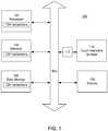
- FIG. 1is a block diagram of an electronic device 100 according to the present invention.
- the device 100includes a touch-sensitive surface 110, for example a touch pad or touch screen. It also includes computing resources, such as processor 102, memory 104 and data storage 106 (e.g., an optical drive, a magnetic media hard drive or a solid state drive).
- Detection circuitry 112provides an interface between the touch-sensitive surface 110 and the rest of the device 100.
- Instructions 124e.g., software
- instructions 124when executed by the processor 102, cause the device to perform certain functions.
- instructions 124include a touch analysis module that analyzes the user interactions with the touch-sensitive surface 110.
- the instructions 124also allow the processor 102 to control a display 120 and to perform other actions on the electronic device.
- the data storage 106includes a machine-readable medium which stores the main body of instructions 124 (e.g., software).
- the instructions 124may also reside, completely or at least partially, within the memory 104 or within the processor 102 (e.g., within a processor's cache memory) during execution.
- the memory 104 and the processor 102also constitute machine-readable media.
- the different componentscommunicate using a common bus, although other communication mechanisms could be used.
- the processor 102could act as a hub with direct access or control over each of the other components.
- the device 100may be a server computer, a client computer, a personal computer (PC), tablet computer, handheld mobile device, or any device capable of executing instructions 124 (sequential or otherwise) that specify actions to be taken by that device.
- the term "device”shall also be taken to include any collection of devices that individually or jointly execute instructions 124 to perform any one or more of the methodologies discussed herein. The same is true for each of the individual components.
- the processor 102may be a multicore processor, or multiple processors working in a coordinated fashion.
- the memory 104 and data storage 106may be dedicated to individual processors, shared by many processors, or a single processor may be served by many memories and data storage.
- the device 100could be a self-contained mobile device, such as a cell phone or tablet computer with a touch screen.
- the touch screenserves as both the touch-sensitive surface 110 and the display 120.
- the device 100could be implemented in a distributed fashion over a network.
- the processor 102could be part of a cloud-based offering (e.g., renting processor time from a cloud offering), the data storage 106 could be network attached storage or other distributed or shared data storage, and the memory 104 could similarly be distributed or shared.
- the touch-sensitive surface 110 and display 120could be user I/O devices to allow the user to interact with the different networked components.
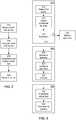
- FIG. 2is a flow diagram illustrating touch interaction using device 100.
- the userinteracts with the touch-sensitive surface 110, for example his hand(s) may form certain poses which are meant to instruct the electronic device to perform corresponding actions.
- the touch-sensitive surface 110 and detection circuitry 112detect 210 this touch interaction.
- the touch-sensitive displaymay be based on resistive, capacitive, optical, acoustic (e.g., surface acoustic wave), force sensing materials (e.g., pressure, shear), piezo material, or other technologies that form the underlying basis for the touch interaction.
- acoustice.g., surface acoustic wave
- force sensing materialse.g., pressure, shear
- piezo materiale.g., piezo material
- a touch analysis module(implemented by instructions 124 in this example) analyzes 220 the detected touch interaction as an initial step to determine the appropriate actions to take. In this example, the analysis determines whether the touch interaction is indicative of a grasp for manipulating a physical tool. If it is, then the electronic device 100 instantiates a corresponding virtual tool that controls an action similar to an action that may be taken by the physical tool. For example, the user may form his hand into the shape for grasping a physical pen, which is intended to instruct the device 100 to instantiate a virtual pen to draw on the display 120.
- the usermay form two hands into the shape for grasping and operating a physical camera, which is intended to instruct the device 100 to instantiate a virtual camera to take a screen shot or to operate a physical camera within the device.
- the touch analysis module 124determines which of these virtual tools, if any, are indicated by the detected touch interaction.
- the processor 102then takes the appropriate actions. It instantiates 230 the corresponding virtual tool and causes an image (or other representation) of the virtual tool to be displayed 230 on the display 120. It also causes any corresponding actions to be performed 240.
- a virtual penis instantiated and an image of a virtual pen is displayed 230.
- the userfurther manipulates the virtual tool (e.g., the virtual pen may move around on the display 120 as the user's grasp moves around on the touch-sensitive surface 110), and the corresponding action of drawing a line also takes place 240.
- the virtual camerawhen the camera grasp is identified 220, then the virtual camera is instantiated and an image of a camera (or a viewfinder, or other image representing the virtual camera) is displayed.
- the virtual cameramay be further manipulated, and the corresponding action of screen capture also takes place 240.
- the usermakes a grasp appropriate for handling a physical tool. This grasp is detected through the touch-sensitive surface.
- the corresponding virtual toolis instantiated and displayed, and the electronic device takes actions that are similar to actions that could be performed by the physical tool.
- FIG. 3is a flow diagram illustrating one approach to analyzing touch interactions. This approach has been successfully implemented on an iPad tablet computer running iOS. The software was implemented in Objective-C++ using the OpenFrameworks application framework. At a high level, this implementation captures 310 the user's touches, classifies 320 the touches using a machine-learning classifier, and then instantiates 330 the user's requested virtual tool.
- the systemdetects 312 a first user touch on the touch screen and then waits 314 thirty milliseconds for additional touches.
- the systemcaptures 314 the touch contacts reported by the touch screen up to that point, and the touches for these contacts are considered to be simultaneous.
- the delayallows the touch screen to have enough time to report all touch contacts, while avoiding excessive latency in instantiating the virtual tool. Other wait times are possible.
- all virtual toolsrequire three or more simultaneous touches. Therefore, if 315 there are two or fewer touches in the captured set, no further classification with respect to virtual tools is needed 316.
- One-touch or two-touch interactionsmay be further interpreted as starting a traditional action, such as tap, pan, pinch-to-zoom, or rotation. This approach means virtual tools can be added as extra functionality for those who have prior experience with one-and two-touch gestures.
- the systemproceeds to classify 320 the tool based on the touch contact pattern formed by the individual touches or touch contacts.
- the systemcomputes 322 a set of features that are a function of the pattern of touch contacts (referred to as the touch contact pattern) and also the x-y positions and the sizes of the individual touch contacts.
- the feature setwas chosen specifically to be rotation invariant, so that the virtual tools can be instantiated at any angle.
- This exemplary feature setincludes the number of touch contacts, the total touch area of the touch contact pattern (i.e., total area for all touch contacts), and the magnitude of the first and second principle components of the touch contact pattern (i.e., the lengths of the major and minor axes of the touch contact pattern).
- This exemplary feature setalso computes 323 statistical quantities (mean, median, min, max, standard deviation) over four sets of data: distances between each pair of touch contacts, distance from each individual touch point to the centroid of the touch contact pattern, angles between consecutively-clockwise touches as measured from the centroid of the touch contact pattern, and the size of each touch contact.
- an exemplary feature setcould include a contour analysis, a histogram of oriented gradients (which counts occurrences of different gradient orientations), first and second principle components of the touch contacts in the touch image (e.g., scale-invariant feature transform), and/or Haar-like features.
- the computed feature set 322 and statistical quantities 323are used as input to a quadratic (non-linear) support vector machine classifier 325, which has been trained on previously recorded data.
- Other classifiersare possible, including decision trees, naive Bayes, and neural networks.
- the virtual tool indicated by the classifier 325is then instantiated 332, making it visible on screen and enabling tool-specific actions 334.
- the process shown in FIG. 3is just one example. Other approaches will be apparent. For example, different features of combinations of features may be used to classify touch interactions. Individual touches may be characterized by size, shape, position, orientation, pressure, temporal duration, and/or contacting part (finger tip, finger nail, finger pad, knuckle, thumb, etc.). These quantities may be absolute or relative.
- the size of a touchmay be the absolute physical size of the touch contact, or the relative size compared to other touches in the touch interaction.
- the positionmay be the absolute position on the touch-sensitive surface, or the relative position within the overall touch contact pattern. Similar possibilities apply to features for the overall touch contact pattern.
- Temporal informationsuch as changes in the touch interaction over time, may also be used.
- information gathered from other sourcesmay also be used to help classify the touch interaction, for example historical data about touch interactions or device usage.
- FIGS. 4-8illustrate different examples of virtual tools. Each figure has three parts A-C.
- Part Ashows a hand grasping a physical tool.
- Part Bshows a hand "grasping" the corresponding virtual tool.
- Part Cshows an example touch contact (a simulated two-dimensional capacitive or pressure image) produced by the hand grasp of Part B.
- FIG. 4Ashows a hand grasping a pen (or other writing instrument).
- FIG. 4Bshows a touch screen displaying a virtual pen, with a hand "grasping" the virtual pen. The pen has just been instantiated on the touch screen. As the user moves his grasp, the virtual pen will draw onto content displayed on the touch screen. Note that the hand grasp is not exactly the same in FIGS. 4A and 4B .
- the grasp in FIG. 4Bis more similar to a hand grasping a pen that is lying on top of the touch screen.
- FIG. 4Cshows an example touch contact pattern (a simulated two-dimensional capacitive image) produced by the fingers of the hand grasp of FIG. 4B .
- touch contact 410 and touch contact 411is a combination of the thumb, fingers, palm and other parts of the hand. Many other touch contacts are possible, possibly user specific, but all are exemplary of hand grasps of tools.
- the hand graspis not required to be one specific grasp.
- Many different types of hand graspsmay be classified as instantiating a virtual pen, for example.
- FIGS.4C and 4Dshow different touch contacts produced by different hand grasps, but both of which are classified as instantiating a virtual pen.
- usersare not required to perform the same grasp exactly the same each time, or even the same grasp as other people.
- a classifiersupports different types of hand grasps. These may be several recognized ways to grasp a pencil for example. The classifer learns the different grasps.
- FIG. 5shows an example using a large eraser.
- FIG. 5Ashows grasping a physical eraser
- FIG. 5Bshows grasping the virtual eraser that is erasing a broad swath.
- FIG. 5Cis the corresponding touch contact pattern (a simulated two-dimensional capacitive image). Compare this to FIGS. 5D-5E.
- FIG. 5Dshows grasping a smaller virtual eraser that erases a narrower swath
- FIG. 5Eshows the corresponding touch contact pattern.
- the two eraserscan be distinguished by different touch contact patterns.
- the touch contact pattern in FIG. 5Cshows a thumb and four fingers while the touch contact pattern in FIG. 5E shows a thumb and only two fingers. Note also that the touch contact pattern in FIG. 5E can be distinguished by the classifier from that in FIG. 4C due to the different spacing between the thumb and the two fingers.
- FIG. 6shows an example using a virtual magnifier to control the action of image zoom.
- secondary actionsmay allow further control of the action.
- the amount of zoommay be adjusted by secondary hand motions.
- one handretains the magnifier grasp and the other hand motions the amount of zoom, or whether to increase or decrease zoom.
- the corresponding touch contact pattern in FIG. 6C(a simulated two-dimensional capacitive image) is not just finger tips. Pressing the hand to the touch screen creates a series of irregular contacts.
- FIG. 7shows an example using a virtual camera to control the action of image capture. This could be operation of the device's camera to capture images of the real world, or it could be capturing screen shots of the display.
- the graspinvolves two hands, which can be seen in the touch contact (a simulated two-dimensional capacitive image) of FIG. 7C .
- the three touch contacts 710are the right thumb, index finger and middle finger; while the three touch contacts 720 are the left thumb, index finger and middle finger.
- the thumb touchesare not finger tip touches. Rather, as can be seen in FIG. 7B , the side of the thumb is contacting the touch screen. This is just one example; other grasps are possible.
- the camera virtual toolis another example of a tool that could have secondary controls.
- buttons on the upper right top of a camerawhich can be depressed to take a photo.
- the usercan make a motion that appears as depressing his right index finger to trigger capturing an image.
- Additional controlssuch as zoom and flash may also be controlled by secondary controls, including other fingers.
- FIG. 8shows an example using a virtual tape measure. As with the camera of FIG. 7 , this grasp also uses two hands. The corresponding action could be measuring a distance, displaying a distance, or other types of distance functions. Note that the touch contact pattern shown in FIG. 8C is for use of a virtual tape measure, but not exactly for the position shown in FIG. 8B .
- FIGS. 4-8are just a few examples. Other examples will be apparent.
- the positions of the touchescould vary from that shown in FIG. 7C .
- the number of touch pointscan also vary.
- the cameracould be held using just four fingers forming a rough rectangle. People can hold objects differently.
- the systemis preferably designed to recognize a wide variety of grasps, not just one.
- virtual paint brushescan be used to control digital painting
- virtual highlighterscan be used to control highlighting.
- Virtual scissors, knives, scalpel or other types of cutting instrumentsmay be used to control digital cutting.
- Virtual tweezers, pliers or other grasping instrumentsmay be used to control digital grabbing of objects.
- Virtual imprint toolsmay be used to control digital stamping.
- Virtual pushpins or other fastenersmay be used to control digital "pinning" objects together.
- graspsmay be recognized based on information beyond or other than just the touch contact patterns.
- the user interfacemay include three- dimensional imaging of the hands (e.g., using a depth camera) and this information could additionally be used to determine the grasps.
- moduleis not meant to be limited to a specific physical form. Depending on the specific application, modules can be implemented as hardware, firmware, software, and/or combinations of these. Furthermore, different modules can share common components or even be implemented by the same components. There may or may not be a clear boundary between different modules.
- the "coupling" between modulesmay also take different forms.
- Dedicated circuitrycan be coupled to each other by hardwiring or by accessing a common register or memory location, for example.
- Software “coupling”can occur by any number of ways to pass information between software components (or between software and hardware, if that is the case).
- the term “coupling”is meant to include all of these and is not meant to be limited to a hardwired permanent connection between two components.
Landscapes
- Engineering & Computer Science (AREA)
- General Engineering & Computer Science (AREA)
- Theoretical Computer Science (AREA)
- Human Computer Interaction (AREA)
- Physics & Mathematics (AREA)
- General Physics & Mathematics (AREA)
- Position Input By Displaying (AREA)
- User Interface Of Digital Computer (AREA)
Description
- This invention relates generally to interacting with electronic devices, for example via a touch-sensitive surface.
- Many touch pads and touch screens today are able to support a small set of gestures. For example, one finger is typically used to manipulate a cursor or to scroll the display. Another example is using two fingers in a pinching manner to zoom in and out of content, such as a photograph or map. However, this is a gross simplification of what fingers and hands are capable of doing. Fingers are diverse appendages, both in their motor capabilities and their anatomical composition. Furthermore, fingers and hands can also be used to manipulate tools, in addition to making gestures themselves.
- Thus, there is a need for better utilization of the capabilities of fingers and hands to control interactions with electronic devices.
US 2010/0306649 provides a virtual inking device created in response to a touch input device detecting a user's inking gesture. For example, when a user places one of their hands in a pen gesture (i.e. by connecting the index finger with the thumb while holding the other fingers near the palm), the user may perform inking operations. When the user changes the pen gesture to an erase gesture (i.e. making a first) then the virtual pen may become a virtual eraser. Other inking gestures may also be utilized.- According to the present invention, there is provided a method of interaction between a user and an electronic device having a touch screen as set out in claim 1. There is also provided a corresponding machine-readable storage medium as set out in claim 13 and a corresponding electronic device as set out in claim 14. The present invention allows users to instantiate and manipulate virtual tools in a manner similar to how they grasp and manipulate the corresponding physical tools.
- In one aspect, an electronic device includes a touch-sensitive surface in the form of a touch screen (which also functions as a display). The user interacts with the touch-sensitive surface, producing touch interactions. Some of these touch interactions may be detected as touch contact patterns including at least three simultaneous contacts on the touch screen that are indicative of a grasp for manipulating a physical tool (e.g., the grasp for holding a pen). When these touch interactions are encountered, a set of features are computed that are a function of the at least three simultaneous touch contacts, the touch interaction is classified as indicative of a particular physical tool, and a corresponding virtual tool is instantiated. The virtual tool controls an action on the electronic device that is similar to an action that can be performed by the physical tool in the real world. For example, the virtual pen can be used to draw on the display, whereas the physical pen draws on paper. An image (or other representation) of the virtual tool is also displayed on a display for the electronic device, at a location that corresponds to a location of the detected touch interaction.
- The action can be controlled by the virtual tool in different ways. For some virtual tools, detecting the correct touch interaction and instantiating the virtual tool may also initiate a corresponding action. For example, a virtual magnifying glass may immediately magnify an area of the display upon instantiation. For other virtual tools, additional actions may be required to specify actions. For example, a virtual pen may require subsequent translation of the touch interaction in order to draw a line on the display. As another example, a virtual camera may require a subsequent motion mimicking pressing a shutter button in order to capture an image. The virtual tool may also move, rotate and/or change in response to these subsequent actions.
- In one approach, touch interactions are classified based on patterns of individual touch contacts. For example, virtual tools may be assigned only to those touch interactions that have three or more simultaneous touch contacts, leaving single-touch and two-touch patterns for existing functions such as scroll or zoom. These more complex touch contact patterns can be classified based on the number of touch contacts, as well as features such as position, shape, size and/or orientation of the touch contacts, both individually and as a whole.
- In another aspect, the type of touch contacts reported by a touch-sensitive surface may vary. In some systems, a touch screen might report a series of touch points (e.g., x/y locations, sometimes with major and minor axes). Other touch screens might provide a two-dimensional image of capacitance, infrared reflectance, z-distance, or other sensing approaches. We use the term "touch contacts" generically to cover all types of touch technologies and capabilities.
- Examples of virtual tools include the following. Virtual pen, pencil, paint brush, highlighter and other writing instruments may be used for drawing lines, digital painting, highlighting and other similar actions. Different types of virtual erasers may be used for erasing. Virtual ruler, tape measure and other distance measuring instruments may be used for functions related to lengths or distances. Virtual scissors, knife and other cutting tools may be used for digital cutting. Virtual camera may be used for image capture. Virtual magnifier may be used for image zoom. Virtual tweezers and other grasping instruments may be used for digital grabbing.
- Other aspects of the invention include methods, devices, systems, components and applications related to the approaches described above.
- The patent or application file contains at least one drawing executed in color. Copies of this patent or patent application publication with color drawing(s) will be provided by the Office upon request and payment of the necessary fee.
- The invention has other advantages and features which will be more readily apparent from the following detailed description of the invention and the appended claims, when taken in conjunction with the accompanying drawings, in which:
FIG. 1 is a block diagram of an electronic device according to the present invention.FIG. 2 is a flow diagram illustrating touch interaction using the device ofFIG. 1 .FIG. 3 is a flow diagram illustrating one approach to analyzing touch interactions.FIGS. 4A-4D illustrate use of a physical pen, use of a virtual pen, and two touch contact patterns for the virtual pen, respectively.FIGS. 5A-5C illustrate use of a physical eraser, use of a virtual eraser, and a touch contact pattern for the virtual eraser, respectively.FIGS. 5D-5E illustrate use of a smaller virtual eraser, and a touch contact pattern for the smaller virtual eraser, respectively.FIGS. 6A-6C illustrate use of a physical magnifier, use of a virtual magnifier, and a touch contact pattern for the virtual magnifier, respectively.FIGS. 7A-7C illustrate use of a physical camera, use of a virtual camera, and a touch contact pattern for the virtual camera, respectively.FIGS. 8A-8C illustrate use of a physical tape measure, use of a virtual tape measure, and a touch contact pattern for the virtual tape measure, respectively.- The figures depict embodiments of the present invention for purposes of illustration only. One skilled in the art will readily recognize from the following discussion that alternative embodiments of the structures and methods illustrated herein may be employed without departing from the principles of the invention described herein.
- The figures and the following description relate to preferred embodiments by way of illustration only. It should be noted that from the following discussion, alternative embodiments of the structures and methods disclosed herein will be readily recognized as viable alternatives that may be employed without departing from the principles of what is claimed.
FIG. 1 is a block diagram of anelectronic device 100 according to the present invention. Thedevice 100 includes a touch-sensitive surface 110, for example a touch pad or touch screen. It also includes computing resources, such asprocessor 102,memory 104 and data storage 106 (e.g., an optical drive, a magnetic media hard drive or a solid state drive).Detection circuitry 112 provides an interface between the touch-sensitive surface 110 and the rest of thedevice 100. Instructions 124 (e.g., software), when executed by theprocessor 102, cause the device to perform certain functions. In this example,instructions 124 include a touch analysis module that analyzes the user interactions with the touch-sensitive surface 110. Theinstructions 124 also allow theprocessor 102 to control adisplay 120 and to perform other actions on the electronic device.- In a common architecture, the
data storage 106 includes a machine-readable medium which stores the main body of instructions 124 (e.g., software). Theinstructions 124 may also reside, completely or at least partially, within thememory 104 or within the processor 102 (e.g., within a processor's cache memory) during execution. Thememory 104 and theprocessor 102 also constitute machine-readable media. - In this example, the different components communicate using a common bus, although other communication mechanisms could be used. As one example, the
processor 102 could act as a hub with direct access or control over each of the other components. - The
device 100 may be a server computer, a client computer, a personal computer (PC), tablet computer, handheld mobile device, or any device capable of executing instructions 124 (sequential or otherwise) that specify actions to be taken by that device. Further, while only a single device is illustrated, the term "device" shall also be taken to include any collection of devices that individually or jointly executeinstructions 124 to perform any one or more of the methodologies discussed herein. The same is true for each of the individual components. For example, theprocessor 102 may be a multicore processor, or multiple processors working in a coordinated fashion. It may also be or include a central processing unit (CPU), a graphics processing unit (GPU), a network processing unit (NPU), a digital signal processor (DSP), one or more application specific integrated circuits (ASICs), or combinations of the foregoing. Thememory 104 anddata storage 106 may be dedicated to individual processors, shared by many processors, or a single processor may be served by many memories and data storage. - As one example, the
device 100 could be a self-contained mobile device, such as a cell phone or tablet computer with a touch screen. In that case, the touch screen serves as both the touch-sensitive surface 110 and thedisplay 120. As another example, thedevice 100 could be implemented in a distributed fashion over a network. Theprocessor 102 could be part of a cloud-based offering (e.g., renting processor time from a cloud offering), thedata storage 106 could be network attached storage or other distributed or shared data storage, and thememory 104 could similarly be distributed or shared. The touch-sensitive surface 110 anddisplay 120 could be user I/O devices to allow the user to interact with the different networked components. FIG. 2 is a flow diagram illustrating touchinteraction using device 100. The user interacts with the touch-sensitive surface 110, for example his hand(s) may form certain poses which are meant to instruct the electronic device to perform corresponding actions. The touch-sensitive surface 110 anddetection circuitry 112 detect 210 this touch interaction. For example, the touch-sensitive display may be based on resistive, capacitive, optical, acoustic (e.g., surface acoustic wave), force sensing materials (e.g., pressure, shear), piezo material, or other technologies that form the underlying basis for the touch interaction. Whatever the underlying principle of operation, touches on the touch-sensitive surface will result in signals. However, these raw signals typically are not directly usable in a digital computing environment. For example, the signals may be analog in nature. Thedetection circuitry 112 typically provides an intermediate stage to process and/or condition these signals so that they are suitable for use in a digital computing environment.- A touch analysis module (implemented by
instructions 124 in this example) analyzes 220 the detected touch interaction as an initial step to determine the appropriate actions to take. In this example, the analysis determines whether the touch interaction is indicative of a grasp for manipulating a physical tool. If it is, then theelectronic device 100 instantiates a corresponding virtual tool that controls an action similar to an action that may be taken by the physical tool. For example, the user may form his hand into the shape for grasping a physical pen, which is intended to instruct thedevice 100 to instantiate a virtual pen to draw on thedisplay 120. As another example, the user may form two hands into the shape for grasping and operating a physical camera, which is intended to instruct thedevice 100 to instantiate a virtual camera to take a screen shot or to operate a physical camera within the device. Thetouch analysis module 124 determines which of these virtual tools, if any, are indicated by the detected touch interaction. - Based on this analysis, the
processor 102 then takes the appropriate actions. It instantiates 230 the corresponding virtual tool and causes an image (or other representation) of the virtual tool to be displayed 230 on thedisplay 120. It also causes any corresponding actions to be performed 240. In the pen example, when the pen grasp is identified 220, then a virtual pen is instantiated and an image of a virtual pen is displayed 230. The user further manipulates the virtual tool (e.g., the virtual pen may move around on thedisplay 120 as the user's grasp moves around on the touch-sensitive surface 110), and the corresponding action of drawing a line also takesplace 240. In the camera example, when the camera grasp is identified 220, then the virtual camera is instantiated and an image of a camera (or a viewfinder, or other image representing the virtual camera) is displayed. The virtual camera may be further manipulated, and the corresponding action of screen capture also takesplace 240. Note the correspondence between the physical world and the virtual world. In the physical world, the user makes a grasp appropriate for handling a physical tool. This grasp is detected through the touch-sensitive surface. The corresponding virtual tool is instantiated and displayed, and the electronic device takes actions that are similar to actions that could be performed by the physical tool. FIG. 3 is a flow diagram illustrating one approach to analyzing touch interactions. This approach has been successfully implemented on an iPad tablet computer running iOS. The software was implemented in Objective-C++ using the OpenFrameworks application framework. At a high level, this implementation captures 310 the user's touches, classifies 320 the touches using a machine-learning classifier, and then instantiates 330 the user's requested virtual tool.- To capture 310 the user's touch interaction, the system detects 312 a first user touch on the touch screen and then waits 314 thirty milliseconds for additional touches. The system captures 314 the touch contacts reported by the touch screen up to that point, and the touches for these contacts are considered to be simultaneous. The delay allows the touch screen to have enough time to report all touch contacts, while avoiding excessive latency in instantiating the virtual tool. Other wait times are possible. In this particular example, all virtual tools require three or more simultaneous touches. Therefore, if 315 there are two or fewer touches in the captured set, no further classification with respect to virtual tools is needed 316. One-touch or two-touch interactions may be further interpreted as starting a traditional action, such as tap, pan, pinch-to-zoom, or rotation. This approach means virtual tools can be added as extra functionality for those who have prior experience with one-and two-touch gestures.
- Otherwise, the system proceeds to classify 320 the tool based on the touch contact pattern formed by the individual touches or touch contacts. In this particular implementation, the system computes 322 a set of features that are a function of the pattern of touch contacts (referred to as the touch contact pattern) and also the x-y positions and the sizes of the individual touch contacts. In this example, the feature set was chosen specifically to be rotation invariant, so that the virtual tools can be instantiated at any angle. This exemplary feature set includes the number of touch contacts, the total touch area of the touch contact pattern (i.e., total area for all touch contacts), and the magnitude of the first and second principle components of the touch contact pattern (i.e., the lengths of the major and minor axes of the touch contact pattern). This exemplary feature set also computes 323 statistical quantities (mean, median, min, max, standard deviation) over four sets of data: distances between each pair of touch contacts, distance from each individual touch point to the centroid of the touch contact pattern, angles between consecutively-clockwise touches as measured from the centroid of the touch contact pattern, and the size of each touch contact.
- This is just one example. Other features and/or statistics could be computed. For example, if a two-dimensional image of the touch contact pattern is available, an exemplary feature set could include a contour analysis, a histogram of oriented gradients (which counts occurrences of different gradient orientations), first and second principle components of the touch contacts in the touch image (e.g., scale-invariant feature transform), and/or Haar-like features.
- The computed
feature set 322 andstatistical quantities 323 are used as input to a quadratic (non-linear) supportvector machine classifier 325, which has been trained on previously recorded data. Other classifiers are possible, including decision trees, naive Bayes, and neural networks. The virtual tool indicated by theclassifier 325 is then instantiated 332, making it visible on screen and enabling tool-specific actions 334. - The process shown in
FIG. 3 is just one example. Other approaches will be apparent. For example, different features of combinations of features may be used to classify touch interactions. Individual touches may be characterized by size, shape, position, orientation, pressure, temporal duration, and/or contacting part (finger tip, finger nail, finger pad, knuckle, thumb, etc.). These quantities may be absolute or relative. For example, the size of a touch may be the absolute physical size of the touch contact, or the relative size compared to other touches in the touch interaction. As another example, the position may be the absolute position on the touch-sensitive surface, or the relative position within the overall touch contact pattern. Similar possibilities apply to features for the overall touch contact pattern. Temporal information, such as changes in the touch interaction over time, may also be used. Furthermore, information gathered from other sources may also be used to help classify the touch interaction, for example historical data about touch interactions or device usage. FIGS. 4-8 illustrate different examples of virtual tools. Each figure has three parts A-C. Part A shows a hand grasping a physical tool. Part B shows a hand "grasping" the corresponding virtual tool. Part C shows an example touch contact (a simulated two-dimensional capacitive or pressure image) produced by the hand grasp of Part B.FIG. 4A shows a hand grasping a pen (or other writing instrument).FIG. 4B shows a touch screen displaying a virtual pen, with a hand "grasping" the virtual pen. The pen has just been instantiated on the touch screen. As the user moves his grasp, the virtual pen will draw onto content displayed on the touch screen. Note that the hand grasp is not exactly the same inFIGS. 4A and 4B . The grasp inFIG. 4B is more similar to a hand grasping a pen that is lying on top of the touch screen.FIG. 4C shows an example touch contact pattern (a simulated two-dimensional capacitive image) produced by the fingers of the hand grasp ofFIG. 4B . In another example shown inFIG. 4D ,touch contact 410 andtouch contact 411 is a combination of the thumb, fingers, palm and other parts of the hand. Many other touch contacts are possible, possibly user specific, but all are exemplary of hand grasps of tools.- Note that, in one approach, the hand grasp is not required to be one specific grasp. Many different types of hand grasps may be classified as instantiating a virtual pen, for example.
FIGS.4C and 4D show different touch contacts produced by different hand grasps, but both of which are classified as instantiating a virtual pen. In this approach, users are not required to perform the same grasp exactly the same each time, or even the same grasp as other people. In one approach, a classifier supports different types of hand grasps. These may be several recognized ways to grasp a pencil for example. The classifer learns the different grasps. FIG. 5 shows an example using a large eraser.FIG. 5A shows grasping a physical eraser,FIG. 5B shows grasping the virtual eraser that is erasing a broad swath.FIG. 5C is the corresponding touch contact pattern (a simulated two-dimensional capacitive image). Compare this toFIGS. 5D-5E. FIG. 5D shows grasping a smaller virtual eraser that erases a narrower swath, andFIG. 5E shows the corresponding touch contact pattern. The two erasers can be distinguished by different touch contact patterns. The touch contact pattern inFIG. 5C shows a thumb and four fingers while the touch contact pattern inFIG. 5E shows a thumb and only two fingers. Note also that the touch contact pattern inFIG. 5E can be distinguished by the classifier from that inFIG. 4C due to the different spacing between the thumb and the two fingers.FIG. 6 shows an example using a virtual magnifier to control the action of image zoom. Once the magnifier grasp is identified, secondary actions may allow further control of the action. For example, the amount of zoom may be adjusted by secondary hand motions. In one example, one hand retains the magnifier grasp and the other hand motions the amount of zoom, or whether to increase or decrease zoom. Note also that the corresponding touch contact pattern inFIG. 6C (a simulated two-dimensional capacitive image) is not just finger tips. Pressing the hand to the touch screen creates a series of irregular contacts.FIG. 7 shows an example using a virtual camera to control the action of image capture. This could be operation of the device's camera to capture images of the real world, or it could be capturing screen shots of the display. Note that the grasp involves two hands, which can be seen in the touch contact (a simulated two-dimensional capacitive image) ofFIG. 7C . The threetouch contacts 710 are the right thumb, index finger and middle finger; while the three touch contacts 720 are the left thumb, index finger and middle finger. Note also that the thumb touches are not finger tip touches. Rather, as can be seen inFIG. 7B , the side of the thumb is contacting the touch screen. This is just one example; other grasps are possible. The camera virtual tool is another example of a tool that could have secondary controls. Typically, there is a button on the upper right top of a camera, which can be depressed to take a photo. Thus, when using the camera virtual tool, the user can make a motion that appears as depressing his right index finger to trigger capturing an image. Additional controls such as zoom and flash may also be controlled by secondary controls, including other fingers.FIG. 8 shows an example using a virtual tape measure. As with the camera ofFIG. 7 , this grasp also uses two hands. The corresponding action could be measuring a distance, displaying a distance, or other types of distance functions. Note that the touch contact pattern shown inFIG. 8C is for use of a virtual tape measure, but not exactly for the position shown inFIG. 8B .FIGS. 4-8 are just a few examples. Other examples will be apparent. For example, for the camera inFIG. 7 , the positions of the touches could vary from that shown inFIG. 7C . The number of touch points can also vary. The camera could be held using just four fingers forming a rough rectangle. People can hold objects differently. In one approach, the system is preferably designed to recognize a wide variety of grasps, not just one.- Other virtual tools can also be realized. For example, virtual paint brushes can be used to control digital painting, and virtual highlighters can be used to control highlighting. There can also be a hierarchy of functions. The pen grasp, pencil grasp, paint brush grasp and highlighter grasp are fairly similar. Rather than trying to distinguish them based solely on the touch interactions, when one of the grasps is encountered, the system may produce a menu listing these different options. The user then selects which virtual tool he would like to use.
- The following are some more examples. Virtual scissors, knives, scalpel or other types of cutting instruments may be used to control digital cutting. Virtual tweezers, pliers or other grasping instruments may be used to control digital grabbing of objects. Virtual imprint tools may be used to control digital stamping. Virtual pushpins or other fasteners may be used to control digital "pinning" objects together.
- As another variation, grasps may be recognized based on information beyond or other than just the touch contact patterns. For example, the user interface may include three- dimensional imaging of the hands (e.g., using a depth camera) and this information could additionally be used to determine the grasps.
- Although the detailed description contains many specifics, these should not be construed as limiting the scope of the invention but merely as illustrating different examples and aspects of the invention. It should be appreciated that the scope of the invention includes other embodiments not discussed in detail above. Various other modifications, changes and variations which will be apparent to those skilled in the art may be made in the arrangement, operation and details of the method and apparatus of the present invention disclosed herein without departing from the scope of the invention as defined in the appended claims. Therefore, the scope of the invention should be determined by the appended claims and their legal equivalents.
- The term "module" is not meant to be limited to a specific physical form. Depending on the specific application, modules can be implemented as hardware, firmware, software, and/or combinations of these. Furthermore, different modules can share common components or even be implemented by the same components. There may or may not be a clear boundary between different modules.
- Depending on the form of the modules, the "coupling" between modules may also take different forms. Dedicated circuitry can be coupled to each other by hardwiring or by accessing a common register or memory location, for example. Software "coupling" can occur by any number of ways to pass information between software components (or between software and hardware, if that is the case). The term "coupling" is meant to include all of these and is not meant to be limited to a hardwired permanent connection between two components. In addition, there may be intervening elements. For example, when two elements are described as being coupled to each other, this does not imply that the elements are directly coupled to each other nor does it preclude the use of other elements between the two.
Claims (14)
- A method of interaction between a user and an electronic device having a touch screen, the method comprising:detecting (310) a touch interaction between the user's one or both hands and the touch screen, wherein the touch interaction comprises a touch contact pattern including at least three simultaneous and individual touch contacts on the touch screen that is indicative of a grasp for manipulating a particular physical tool;computing (322) a set of features that are a function of the pattern of the at least three simultaneous and individual touch contacts;classifying (325) the touch interaction as indicative of the particular physical tool based on the computed set of features; andin response to classifying the touch interaction as indicative of the particular physical tool, instantiating (330) a virtual tool corresponding to the particular physical tool, wherein the virtual tool controls an action on the electronic device that is similar to an action that can be performed by the particular physical tool, and wherein instantiating the virtual tool includes displaying a representation of the virtual tool on the touch screen at a location of the detected touch interaction such that it appears the user is grasping the virtual tool.
- The method of claim 1, further comprising: in response to detecting the touch interaction, performing the action controlled by the virtual tool on the electronic device.
- The method of claim 1, further comprising:detecting motion of the touch interaction; andin response to detecting the motion, adjusting the representation of the virtual tool according to the detected motion and performing the action controlled by the virtual tool according to the detected motion.
- The method of claim 1, further comprising:after instantiating the virtual tool, detecting an additional action made by the user; andin response to detecting the additional user action, performing the action controlled by the virtual tool according to the additional user action.
- The method of claim 1, wherein the representation of the virtual tool is an image of the particular physical tool.
- The method of claim 1, further comprising: learning different grasps using previously recorded data.
- The method of claim 1, wherein the touch interaction is indicative of a grasp for grasping the particular physical tool lying on the touch screen.
- The method of claim 1, wherein the detecting the touch interaction includes determining at least one of a shape, an outline, a size or an orientation of the touch contact pattern.
- The method of claim 1, wherein the detecting the touch interaction includes determining a number of simultaneous and individual touch contacts associated with the touch interaction.
- The method of claim 1, wherein the detecting the touch interaction includes determining a relative positioning of the at least three simultaneous and individual touch contacts on the screen associated with the touch interaction.
- The method of claim 1, wherein the detecting the touch interaction includes determining a change in the touch interaction over time.
- The method of claim 1 wherein the particular physical tool is one of:a writing instrument, and the action controlled by the virtual tool is drawing;a paintbrush, and the action controlled by the virtual tool is digital painting;a highlighter, and the action controlled by the virtual tool is highlighting;an eraser, and the action controlled by the virtual tool is erasing;a distance measuring instrument, and the action controlled by the virtual tool is measuring a distance;a distance measuring instrument, and the action controlled by the virtual tool is displaying a distance;a cutting instrument, and the action controlled by the virtual tool is digital cutting;a camera, and the action controlled by the virtual tool is image capture;a magnifier, and the action controlled by the virtual tool is image zoom;an imprint tool, and the action controlled by the virtual tool is digital stamping;a grasping instrument, and the action controlled by the virtual tool is digital grabbing; anda fastener, and the action controlled by the virtual tool is digital pinning.
- A machine-readable tangible storage medium having stored thereon data representing sequences of instructions, which when executed by an electronic device having a touch screen, cause the electronic device to perform the method of any preceding claim.
- An electronic device comprising:a touch screen;detection circuitry coupled to the touch screen, configured for detecting (310) a touch interaction between a user's one or both hands and the touch screen, wherein the touch interaction comprises a touch contact pattern including at least three simultaneous and individual touch contacts on the touch screen that is indicative of a grasp for manipulating a particular physical tool;a touch analysis module coupled to the detection circuitry, configured for computing (322) a set of features that are a function of the pattern of the at least three simultaneous and individual touch contacts, and configured for classifying (325) the touch interaction as indicative of the particular physical tool based on the computed set of features; anda processor coupled to the touch analysis module, the processor configured for, in response to classifying the touch interaction as indicative of the particular physical tool, instantiating a virtual tool corresponding to the particular physical tool, wherein the virtual tool controls an action on the electronic device that is similar to an action that can be performed by the particular physical tool and instantiating the virtual tool includes displaying a representation of the virtual tool on the touch screen at a location of the detected touch interaction such that it appears the user is grasping the virtual tool.
Applications Claiming Priority (2)
| Application Number | Priority Date | Filing Date | Title |
|---|---|---|---|
| US13/863,193US10082935B2 (en) | 2013-04-15 | 2013-04-15 | Virtual tools for use with touch-sensitive surfaces |
| PCT/US2014/033380WO2014172148A2 (en) | 2013-04-15 | 2014-04-08 | Virtual tools for use with touch-sensitive surfaces |
Publications (3)
| Publication Number | Publication Date |
|---|---|
| EP2987063A2 EP2987063A2 (en) | 2016-02-24 |
| EP2987063A4 EP2987063A4 (en) | 2016-09-14 |
| EP2987063B1true EP2987063B1 (en) | 2020-01-01 |
Family
ID=51687676
Family Applications (1)
| Application Number | Title | Priority Date | Filing Date |
|---|---|---|---|
| EP14785422.8AActiveEP2987063B1 (en) | 2013-04-15 | 2014-04-08 | Virtual tools for use with touch-sensitive surfaces |
Country Status (4)
| Country | Link |
|---|---|
| US (1) | US10082935B2 (en) |
| EP (1) | EP2987063B1 (en) |
| CN (1) | CN105210012B (en) |
| WO (1) | WO2014172148A2 (en) |
Families Citing this family (31)
| Publication number | Priority date | Publication date | Assignee | Title |
|---|---|---|---|---|
| KR102027601B1 (en) | 2011-10-18 | 2019-10-01 | 카네기 멜론 유니버시티 | Method and apparatus for classifying touch events on a touch sensitive surface |
| KR20140114766A (en) | 2013-03-19 | 2014-09-29 | 퀵소 코 | Method and device for sensing touch inputs |
| US9612689B2 (en) | 2015-02-02 | 2017-04-04 | Qeexo, Co. | Method and apparatus for classifying a touch event on a touchscreen as related to one of multiple function generating interaction layers and activating a function in the selected interaction layer |
| US9013452B2 (en) | 2013-03-25 | 2015-04-21 | Qeexo, Co. | Method and system for activating different interactive functions using different types of finger contacts |
| US20190004698A1 (en)* | 2013-04-15 | 2019-01-03 | Carnegie Mellon University | Virtual tools for use with touch-sensitive surfaces |
| US20150046862A1 (en)* | 2013-08-11 | 2015-02-12 | Silicon Graphics International Corp. | Modifying binning operations |
| US9477403B2 (en)* | 2013-11-26 | 2016-10-25 | Adobe Systems Incorporated | Drawing on a touchscreen |
| US11144184B2 (en) | 2014-01-23 | 2021-10-12 | Mineset, Inc. | Selection thresholds in a visualization interface |
| US10528155B2 (en) | 2014-02-13 | 2020-01-07 | Microsoft Technology Licensing, Llc | Low-profile pointing stick |
| US10627918B2 (en) | 2014-02-13 | 2020-04-21 | Microsoft Technology Licensing, Llc | Low-profile pointing stick |
| US9874945B2 (en)* | 2014-02-13 | 2018-01-23 | Microsoft Technology Licensing, Llc | Low-profile pointing stick |
| US9329715B2 (en) | 2014-09-11 | 2016-05-03 | Qeexo, Co. | Method and apparatus for differentiating touch screen users based on touch event analysis |
| US11619983B2 (en) | 2014-09-15 | 2023-04-04 | Qeexo, Co. | Method and apparatus for resolving touch screen ambiguities |
| US10606417B2 (en) | 2014-09-24 | 2020-03-31 | Qeexo, Co. | Method for improving accuracy of touch screen event analysis by use of spatiotemporal touch patterns |
| US10007421B2 (en)* | 2015-08-03 | 2018-06-26 | Lenovo (Singapore) Pte. Ltd. | Natural handwriting detection on a touch surface |
| US10642404B2 (en) | 2015-08-24 | 2020-05-05 | Qeexo, Co. | Touch sensitive device with multi-sensor stream synchronized data |
| CN110058782B (en)* | 2016-02-22 | 2020-11-24 | 广州视睿电子科技有限公司 | Touch operation method and system based on interactive electronic whiteboard |
| US10871880B2 (en) | 2016-11-04 | 2020-12-22 | Microsoft Technology Licensing, Llc | Action-enabled inking tools |
| JP6903999B2 (en)* | 2017-03-29 | 2021-07-14 | 富士フイルムビジネスイノベーション株式会社 | Content display device and content display program |
| US10650565B2 (en)* | 2017-06-02 | 2020-05-12 | Apple Inc. | Rendering animated user input strokes |
| US10768780B2 (en) | 2017-12-11 | 2020-09-08 | International Business Machines Corporation | Method and system for context-driven displaying of shortcuts on touchscreen |
| CN110543246A (en)* | 2018-05-28 | 2019-12-06 | 深圳市鸿合创新信息技术有限责任公司 | touch event processing method and touch screen device |
| WO2020028826A1 (en)* | 2018-08-02 | 2020-02-06 | Firefly Dimension, Inc. | System and method for human interaction with virtual objects |
| US11009989B2 (en) | 2018-08-21 | 2021-05-18 | Qeexo, Co. | Recognizing and rejecting unintentional touch events associated with a touch sensitive device |
| US10942603B2 (en) | 2019-05-06 | 2021-03-09 | Qeexo, Co. | Managing activity states of an application processor in relation to touch or hover interactions with a touch sensitive device |
| US11231815B2 (en) | 2019-06-28 | 2022-01-25 | Qeexo, Co. | Detecting object proximity using touch sensitive surface sensing and ultrasonic sensing |
| DE102020130987A1 (en) | 2020-01-24 | 2021-07-29 | Schaeffler Technologies AG & Co. KG | Method for producing a component of an electric motor, an electric motor component and an electric motor |
| US11592423B2 (en) | 2020-01-29 | 2023-02-28 | Qeexo, Co. | Adaptive ultrasonic sensing techniques and systems to mitigate interference |
| DE102020113047A1 (en) | 2020-05-14 | 2021-11-18 | Schaeffler Technologies AG & Co. KG | Electric motor component and method for manufacturing an electric motor component of an axial flux motor |
| CN112241231B (en)* | 2020-10-22 | 2021-12-07 | 北京字节跳动网络技术有限公司 | Method, device and computer readable storage medium for constructing virtual assembly |
| US11886768B2 (en)* | 2022-04-29 | 2024-01-30 | Adobe Inc. | Real time generative audio for brush and canvas interaction in digital drawing |
Family Cites Families (49)
| Publication number | Priority date | Publication date | Assignee | Title |
|---|---|---|---|---|
| US5483261A (en)* | 1992-02-14 | 1996-01-09 | Itu Research, Inc. | Graphical input controller and method with rear screen image detection |
| US20020126161A1 (en)* | 1994-07-05 | 2002-09-12 | Hitachi, Ltd. | Information processing system |
| US6028593A (en)* | 1995-12-01 | 2000-02-22 | Immersion Corporation | Method and apparatus for providing simulated physical interactions within computer generated environments |
| US5867163A (en)* | 1995-12-01 | 1999-02-02 | Silicon Graphics, Inc. | Graphical user interface for defining and invoking user-customized tool shelf execution sequence |
| US7084884B1 (en)* | 1998-11-03 | 2006-08-01 | Immersion Corporation | Graphical object interactions |
| US6337698B1 (en)* | 1998-11-20 | 2002-01-08 | Microsoft Corporation | Pen-based interface for a notepad computer |
| US6222465B1 (en)* | 1998-12-09 | 2001-04-24 | Lucent Technologies Inc. | Gesture-based computer interface |
| US7212197B1 (en)* | 1999-02-01 | 2007-05-01 | California Institute Of Technology | Three dimensional surface drawing controlled by hand motion |
| US7050955B1 (en)* | 1999-10-01 | 2006-05-23 | Immersion Corporation | System, method and data structure for simulated interaction with graphical objects |
| US6772396B1 (en) | 1999-10-07 | 2004-08-03 | Microsoft Corporation | Content distribution system for network environments |
| US7443396B2 (en)* | 2000-11-29 | 2008-10-28 | National Instruments Corporation | Instrument having a virtual magnifying glass for displaying magnified portions of a signal waveform |
| US7058902B2 (en)* | 2002-07-30 | 2006-06-06 | Microsoft Corporation | Enhanced on-object context menus |
| US7814439B2 (en)* | 2002-10-18 | 2010-10-12 | Autodesk, Inc. | Pan-zoom tool |
| US7593593B2 (en)* | 2004-06-16 | 2009-09-22 | Microsoft Corporation | Method and system for reducing effects of undesired signals in an infrared imaging system |
| US7519223B2 (en)* | 2004-06-28 | 2009-04-14 | Microsoft Corporation | Recognizing gestures and using gestures for interacting with software applications |
| US7847789B2 (en) | 2004-11-23 | 2010-12-07 | Microsoft Corporation | Reducing accidental touch-sensitive device activation |
| US8018579B1 (en) | 2005-10-21 | 2011-09-13 | Apple Inc. | Three-dimensional imaging and display system |
| US8086971B2 (en)* | 2006-06-28 | 2011-12-27 | Nokia Corporation | Apparatus, methods and computer program products providing finger-based and hand-based gesture commands for portable electronic device applications |
| US8180114B2 (en)* | 2006-07-13 | 2012-05-15 | Northrop Grumman Systems Corporation | Gesture recognition interface system with vertical display |
| EP1909162A1 (en)* | 2006-10-02 | 2008-04-09 | Koninklijke Philips Electronics N.V. | System for virtually drawing on a physical surface |
| KR100790896B1 (en)* | 2006-11-17 | 2008-01-03 | 삼성전자주식회사 | Method and device for controlling application using movement of imager |
| US7877707B2 (en)* | 2007-01-06 | 2011-01-25 | Apple Inc. | Detecting and interpreting real-world and security gestures on touch and hover sensitive devices |
| WO2008095139A2 (en)* | 2007-01-31 | 2008-08-07 | Perceptive Pixel, Inc. | Methods of interfacing with multi-point input devices and multi-point input systems employing interfacing techniques |
| US7911453B2 (en)* | 2007-06-29 | 2011-03-22 | Microsoft Corporation | Creating virtual replicas of physical objects |
| US8564574B2 (en)* | 2007-09-18 | 2013-10-22 | Acer Incorporated | Input apparatus with multi-mode switching function |
| WO2009047759A2 (en)* | 2007-10-11 | 2009-04-16 | N-Trig Ltd. | Method for palm touch identification in multi-touch digitizing systems |
| US8413075B2 (en)* | 2008-01-04 | 2013-04-02 | Apple Inc. | Gesture movies |
| WO2009152603A1 (en) | 2008-06-18 | 2009-12-23 | Chalk Media Service Corp. | Method and system for republishing mobile content |
| US8154524B2 (en)* | 2008-06-24 | 2012-04-10 | Microsoft Corporation | Physics simulation-based interaction for surface computing |
| US8386963B2 (en)* | 2009-05-28 | 2013-02-26 | Microsoft Corporation | Virtual inking using gesture recognition |
| US8275590B2 (en)* | 2009-08-12 | 2012-09-25 | Zugara, Inc. | Providing a simulation of wearing items such as garments and/or accessories |
| US8441790B2 (en) | 2009-08-17 | 2013-05-14 | Apple Inc. | Electronic device housing as acoustic input device |
| US8232990B2 (en)* | 2010-01-05 | 2012-07-31 | Apple Inc. | Working with 3D objects |
| US8842096B2 (en)* | 2010-01-08 | 2014-09-23 | Crayola Llc | Interactive projection system |
| US8487889B2 (en)* | 2010-01-15 | 2013-07-16 | Apple Inc. | Virtual drafting tools |
| US9003334B2 (en)* | 2010-03-05 | 2015-04-07 | Adobe Systems Incorporated | Editing content using multiple touch inputs |
| US8576253B2 (en)* | 2010-04-27 | 2013-11-05 | Microsoft Corporation | Grasp simulation of a virtual object |
| WO2012030958A1 (en) | 2010-08-31 | 2012-03-08 | Activate Systems, Inc. | Methods and apparatus for improved motion capture |
| US8988398B2 (en)* | 2011-02-11 | 2015-03-24 | Microsoft Corporation | Multi-touch input device with orientation sensing |
| US9182882B2 (en)* | 2011-04-12 | 2015-11-10 | Autodesk, Inc. | Dynamic creation and modeling of solid models |
| US9898122B2 (en)* | 2011-05-12 | 2018-02-20 | Google Technology Holdings LLC | Touch-screen device and method for detecting and ignoring false touch inputs near an edge of the touch-screen device |
| TWI478041B (en) | 2011-05-17 | 2015-03-21 | Elan Microelectronics Corp | Method of identifying palm area of a touch panel and a updating method thereof |
| US8896555B2 (en)* | 2011-05-20 | 2014-11-25 | Robert H Duffield | Touch alphabet and communication system |
| US8760395B2 (en)* | 2011-05-31 | 2014-06-24 | Microsoft Corporation | Gesture recognition techniques |
| US9075561B2 (en) | 2011-07-29 | 2015-07-07 | Apple Inc. | Systems, methods, and computer-readable media for managing collaboration on a virtual work of art |
| US9030498B2 (en)* | 2011-08-15 | 2015-05-12 | Apple Inc. | Combining explicit select gestures and timeclick in a non-tactile three dimensional user interface |
| WO2013095679A1 (en)* | 2011-12-23 | 2013-06-27 | Intel Corporation | Computing system utilizing coordinated two-hand command gestures |
| AU2013239179B2 (en)* | 2012-03-26 | 2015-08-20 | Apple Inc. | Enhanced virtual touchpad and touchscreen |
| US9552673B2 (en)* | 2012-10-17 | 2017-01-24 | Microsoft Technology Licensing, Llc | Grasping virtual objects in augmented reality |
- 2013
- 2013-04-15USUS13/863,193patent/US10082935B2/enactiveActive
- 2014
- 2014-04-08WOPCT/US2014/033380patent/WO2014172148A2/enactiveApplication Filing
- 2014-04-08CNCN201480022056.5Apatent/CN105210012B/enactiveActive
- 2014-04-08EPEP14785422.8Apatent/EP2987063B1/enactiveActive
Non-Patent Citations (1)
| Title |
|---|
| None* |
Also Published As
| Publication number | Publication date |
|---|---|
| CN105210012A (en) | 2015-12-30 |
| WO2014172148A3 (en) | 2015-05-07 |
| CN105210012B (en) | 2019-04-05 |
| EP2987063A2 (en) | 2016-02-24 |
| US10082935B2 (en) | 2018-09-25 |
| US20140310631A1 (en) | 2014-10-16 |
| WO2014172148A2 (en) | 2014-10-23 |
| EP2987063A4 (en) | 2016-09-14 |
Similar Documents
| Publication | Publication Date | Title |
|---|---|---|
| EP2987063B1 (en) | Virtual tools for use with touch-sensitive surfaces | |
| US11048333B2 (en) | System and method for close-range movement tracking | |
| US12073008B2 (en) | Three-dimensional object tracking to augment display area | |
| US9910498B2 (en) | System and method for close-range movement tracking | |
| CN109074217B (en) | Application for multi-touch input detection | |
| KR102407071B1 (en) | Multi-device multi-user sensor correlation for pen and computing device interaction | |
| JP6660309B2 (en) | Sensor correlation for pen and touch-sensitive computing device interaction | |
| Murugappan et al. | Extended multitouch: recovering touch posture and differentiating users using a depth camera | |
| US20140123077A1 (en) | System and method for user interaction and control of electronic devices | |
| US20190004698A1 (en) | Virtual tools for use with touch-sensitive surfaces | |
| KR20160080109A (en) | Systems and techniques for user interface control | |
| JP2013037675A5 (en) | ||
| Mallik et al. | Virtual Keyboard: A Real-Time Hand Gesture Recognition-Based Character Input System Using LSTM and Mediapipe Holistic. | |
| Matulic et al. | Hand contact shape recognition for posture-based tabletop widgets and interaction | |
| WO2013054155A1 (en) | Multi-touch human interface system and device for graphical input, and method for processing image in such a system. | |
| Annabel et al. | Design and Development of Multimodal Virtual Mouse | |
| US20250291421A1 (en) | Input apparatus and method | |
| Dave et al. | Project MUDRA: Personalization of Computers using Natural Interface | |
| Murugappana et al. | Extended multitouch: Recovering touch posture, handedness, and user identity using a depth camera | |
| Matulic et al. | Deep Learning-Based Hand Posture Recognition for Pen Interaction Enhancement | |
| CN118377373A (en) | Hand-eye coordination computer control system and method based on MR equipment | |
| CN120255729A (en) | A method, device, equipment, medium and product for realizing floating touch | |
| TWM635698U (en) | virtual mouse controller | |
| Zhang | Various Techniques of Mode Changing with Stylus/Touch Interface | |
| HK1171826B (en) | Multi-touch input device with orientation sensing |
Legal Events
| Date | Code | Title | Description |
|---|---|---|---|
| PUAI | Public reference made under article 153(3) epc to a published international application that has entered the european phase | Free format text:ORIGINAL CODE: 0009012 | |
| 17P | Request for examination filed | Effective date:20150820 | |
| AK | Designated contracting states | Kind code of ref document:A2 Designated state(s):AL AT BE BG CH CY CZ DE DK EE ES FI FR GB GR HR HU IE IS IT LI LT LU LV MC MK MT NL NO PL PT RO RS SE SI SK SM TR | |
| AX | Request for extension of the european patent | Extension state:BA ME | |
| RIN1 | Information on inventor provided before grant (corrected) | Inventor name:HARRISON, CHRISTOPHER Inventor name:HUDSON, SCOTT, E. Inventor name:SCHWARZ, JULIA Inventor name:XIAO, ROBERT, BO | |
| DAX | Request for extension of the european patent (deleted) | ||
| A4 | Supplementary search report drawn up and despatched | Effective date:20160811 | |
| RIC1 | Information provided on ipc code assigned before grant | Ipc:G06F 3/0488 20130101AFI20160805BHEP | |
| STAA | Information on the status of an ep patent application or granted ep patent | Free format text:STATUS: EXAMINATION IS IN PROGRESS | |
| 17Q | First examination report despatched | Effective date:20180226 | |
| REG | Reference to a national code | Ref country code:DE Ref legal event code:R079 Ref document number:602014059361 Country of ref document:DE Free format text:PREVIOUS MAIN CLASS: G06F0003041000 Ipc:G06F0003048400 | |
| GRAP | Despatch of communication of intention to grant a patent | Free format text:ORIGINAL CODE: EPIDOSNIGR1 | |
| STAA | Information on the status of an ep patent application or granted ep patent | Free format text:STATUS: GRANT OF PATENT IS INTENDED | |
| RIC1 | Information provided on ipc code assigned before grant | Ipc:G06F 3/0488 20130101ALI20190218BHEP Ipc:G06F 3/0484 20130101AFI20190218BHEP | |
| INTG | Intention to grant announced | Effective date:20190306 | |
| GRAJ | Information related to disapproval of communication of intention to grant by the applicant or resumption of examination proceedings by the epo deleted | Free format text:ORIGINAL CODE: EPIDOSDIGR1 | |
| STAA | Information on the status of an ep patent application or granted ep patent | Free format text:STATUS: EXAMINATION IS IN PROGRESS | |
| GRAP | Despatch of communication of intention to grant a patent | Free format text:ORIGINAL CODE: EPIDOSNIGR1 | |
| STAA | Information on the status of an ep patent application or granted ep patent | Free format text:STATUS: GRANT OF PATENT IS INTENDED | |
| INTC | Intention to grant announced (deleted) | ||
| INTG | Intention to grant announced | Effective date:20190729 | |
| GRAS | Grant fee paid | Free format text:ORIGINAL CODE: EPIDOSNIGR3 | |
| GRAA | (expected) grant | Free format text:ORIGINAL CODE: 0009210 | |
| STAA | Information on the status of an ep patent application or granted ep patent | Free format text:STATUS: THE PATENT HAS BEEN GRANTED | |
| AK | Designated contracting states | Kind code of ref document:B1 Designated state(s):AL AT BE BG CH CY CZ DE DK EE ES FI FR GB GR HR HU IE IS IT LI LT LU LV MC MK MT NL NO PL PT RO RS SE SI SK SM TR | |
| REG | Reference to a national code | Ref country code:GB Ref legal event code:FG4D | |
| REG | Reference to a national code | Ref country code:CH Ref legal event code:EP Ref country code:AT Ref legal event code:REF Ref document number:1220626 Country of ref document:AT Kind code of ref document:T Effective date:20200115 | |
| REG | Reference to a national code | Ref country code:IE Ref legal event code:FG4D | |
| REG | Reference to a national code | Ref country code:DE Ref legal event code:R096 Ref document number:602014059361 Country of ref document:DE | |
| REG | Reference to a national code | Ref country code:NL Ref legal event code:MP Effective date:20200101 | |
| REG | Reference to a national code | Ref country code:LT Ref legal event code:MG4D | |
| PG25 | Lapsed in a contracting state [announced via postgrant information from national office to epo] | Ref country code:NO Free format text:LAPSE BECAUSE OF FAILURE TO SUBMIT A TRANSLATION OF THE DESCRIPTION OR TO PAY THE FEE WITHIN THE PRESCRIBED TIME-LIMIT Effective date:20200401 Ref country code:FI Free format text:LAPSE BECAUSE OF FAILURE TO SUBMIT A TRANSLATION OF THE DESCRIPTION OR TO PAY THE FEE WITHIN THE PRESCRIBED TIME-LIMIT Effective date:20200101 Ref country code:PT Free format text:LAPSE BECAUSE OF FAILURE TO SUBMIT A TRANSLATION OF THE DESCRIPTION OR TO PAY THE FEE WITHIN THE PRESCRIBED TIME-LIMIT Effective date:20200527 Ref country code:LT Free format text:LAPSE BECAUSE OF FAILURE TO SUBMIT A TRANSLATION OF THE DESCRIPTION OR TO PAY THE FEE WITHIN THE PRESCRIBED TIME-LIMIT Effective date:20200101 Ref country code:RS Free format text:LAPSE BECAUSE OF FAILURE TO SUBMIT A TRANSLATION OF THE DESCRIPTION OR TO PAY THE FEE WITHIN THE PRESCRIBED TIME-LIMIT Effective date:20200101 Ref country code:CZ Free format text:LAPSE BECAUSE OF FAILURE TO SUBMIT A TRANSLATION OF THE DESCRIPTION OR TO PAY THE FEE WITHIN THE PRESCRIBED TIME-LIMIT Effective date:20200101 Ref country code:NL Free format text:LAPSE BECAUSE OF FAILURE TO SUBMIT A TRANSLATION OF THE DESCRIPTION OR TO PAY THE FEE WITHIN THE PRESCRIBED TIME-LIMIT Effective date:20200101 | |
| PG25 | Lapsed in a contracting state [announced via postgrant information from national office to epo] | Ref country code:LV Free format text:LAPSE BECAUSE OF FAILURE TO SUBMIT A TRANSLATION OF THE DESCRIPTION OR TO PAY THE FEE WITHIN THE PRESCRIBED TIME-LIMIT Effective date:20200101 Ref country code:IS Free format text:LAPSE BECAUSE OF FAILURE TO SUBMIT A TRANSLATION OF THE DESCRIPTION OR TO PAY THE FEE WITHIN THE PRESCRIBED TIME-LIMIT Effective date:20200501 Ref country code:SE Free format text:LAPSE BECAUSE OF FAILURE TO SUBMIT A TRANSLATION OF THE DESCRIPTION OR TO PAY THE FEE WITHIN THE PRESCRIBED TIME-LIMIT Effective date:20200101 Ref country code:GR Free format text:LAPSE BECAUSE OF FAILURE TO SUBMIT A TRANSLATION OF THE DESCRIPTION OR TO PAY THE FEE WITHIN THE PRESCRIBED TIME-LIMIT Effective date:20200402 Ref country code:HR Free format text:LAPSE BECAUSE OF FAILURE TO SUBMIT A TRANSLATION OF THE DESCRIPTION OR TO PAY THE FEE WITHIN THE PRESCRIBED TIME-LIMIT Effective date:20200101 Ref country code:BG Free format text:LAPSE BECAUSE OF FAILURE TO SUBMIT A TRANSLATION OF THE DESCRIPTION OR TO PAY THE FEE WITHIN THE PRESCRIBED TIME-LIMIT Effective date:20200401 | |
| REG | Reference to a national code | Ref country code:DE Ref legal event code:R097 Ref document number:602014059361 Country of ref document:DE | |
| PG25 | Lapsed in a contracting state [announced via postgrant information from national office to epo] | Ref country code:SM Free format text:LAPSE BECAUSE OF FAILURE TO SUBMIT A TRANSLATION OF THE DESCRIPTION OR TO PAY THE FEE WITHIN THE PRESCRIBED TIME-LIMIT Effective date:20200101 Ref country code:EE Free format text:LAPSE BECAUSE OF FAILURE TO SUBMIT A TRANSLATION OF THE DESCRIPTION OR TO PAY THE FEE WITHIN THE PRESCRIBED TIME-LIMIT Effective date:20200101 Ref country code:ES Free format text:LAPSE BECAUSE OF FAILURE TO SUBMIT A TRANSLATION OF THE DESCRIPTION OR TO PAY THE FEE WITHIN THE PRESCRIBED TIME-LIMIT Effective date:20200101 Ref country code:RO Free format text:LAPSE BECAUSE OF FAILURE TO SUBMIT A TRANSLATION OF THE DESCRIPTION OR TO PAY THE FEE WITHIN THE PRESCRIBED TIME-LIMIT Effective date:20200101 Ref country code:SK Free format text:LAPSE BECAUSE OF FAILURE TO SUBMIT A TRANSLATION OF THE DESCRIPTION OR TO PAY THE FEE WITHIN THE PRESCRIBED TIME-LIMIT Effective date:20200101 Ref country code:DK Free format text:LAPSE BECAUSE OF FAILURE TO SUBMIT A TRANSLATION OF THE DESCRIPTION OR TO PAY THE FEE WITHIN THE PRESCRIBED TIME-LIMIT Effective date:20200101 | |
| PLBE | No opposition filed within time limit | Free format text:ORIGINAL CODE: 0009261 | |
| STAA | Information on the status of an ep patent application or granted ep patent | Free format text:STATUS: NO OPPOSITION FILED WITHIN TIME LIMIT | |
| REG | Reference to a national code | Ref country code:AT Ref legal event code:MK05 Ref document number:1220626 Country of ref document:AT Kind code of ref document:T Effective date:20200101 | |
| PG25 | Lapsed in a contracting state [announced via postgrant information from national office to epo] | Ref country code:MC Free format text:LAPSE BECAUSE OF FAILURE TO SUBMIT A TRANSLATION OF THE DESCRIPTION OR TO PAY THE FEE WITHIN THE PRESCRIBED TIME-LIMIT Effective date:20200101 | |
| REG | Reference to a national code | Ref country code:CH Ref legal event code:PL | |
| 26N | No opposition filed | Effective date:20201002 | |
| PG25 | Lapsed in a contracting state [announced via postgrant information from national office to epo] | Ref country code:CH Free format text:LAPSE BECAUSE OF NON-PAYMENT OF DUE FEES Effective date:20200430 Ref country code:LI Free format text:LAPSE BECAUSE OF NON-PAYMENT OF DUE FEES Effective date:20200430 Ref country code:LU Free format text:LAPSE BECAUSE OF NON-PAYMENT OF DUE FEES Effective date:20200408 Ref country code:AT Free format text:LAPSE BECAUSE OF FAILURE TO SUBMIT A TRANSLATION OF THE DESCRIPTION OR TO PAY THE FEE WITHIN THE PRESCRIBED TIME-LIMIT Effective date:20200101 Ref country code:IT Free format text:LAPSE BECAUSE OF FAILURE TO SUBMIT A TRANSLATION OF THE DESCRIPTION OR TO PAY THE FEE WITHIN THE PRESCRIBED TIME-LIMIT Effective date:20200101 | |
| REG | Reference to a national code | Ref country code:BE Ref legal event code:MM Effective date:20200430 | |
| PG25 | Lapsed in a contracting state [announced via postgrant information from national office to epo] | Ref country code:SI Free format text:LAPSE BECAUSE OF FAILURE TO SUBMIT A TRANSLATION OF THE DESCRIPTION OR TO PAY THE FEE WITHIN THE PRESCRIBED TIME-LIMIT Effective date:20200101 Ref country code:PL Free format text:LAPSE BECAUSE OF FAILURE TO SUBMIT A TRANSLATION OF THE DESCRIPTION OR TO PAY THE FEE WITHIN THE PRESCRIBED TIME-LIMIT Effective date:20200101 Ref country code:BE Free format text:LAPSE BECAUSE OF NON-PAYMENT OF DUE FEES Effective date:20200430 | |
| PG25 | Lapsed in a contracting state [announced via postgrant information from national office to epo] | Ref country code:IE Free format text:LAPSE BECAUSE OF NON-PAYMENT OF DUE FEES Effective date:20200408 | |
| PG25 | Lapsed in a contracting state [announced via postgrant information from national office to epo] | Ref country code:TR Free format text:LAPSE BECAUSE OF FAILURE TO SUBMIT A TRANSLATION OF THE DESCRIPTION OR TO PAY THE FEE WITHIN THE PRESCRIBED TIME-LIMIT Effective date:20200101 Ref country code:MT Free format text:LAPSE BECAUSE OF FAILURE TO SUBMIT A TRANSLATION OF THE DESCRIPTION OR TO PAY THE FEE WITHIN THE PRESCRIBED TIME-LIMIT Effective date:20200101 Ref country code:CY Free format text:LAPSE BECAUSE OF FAILURE TO SUBMIT A TRANSLATION OF THE DESCRIPTION OR TO PAY THE FEE WITHIN THE PRESCRIBED TIME-LIMIT Effective date:20200101 | |
| PG25 | Lapsed in a contracting state [announced via postgrant information from national office to epo] | Ref country code:MK Free format text:LAPSE BECAUSE OF FAILURE TO SUBMIT A TRANSLATION OF THE DESCRIPTION OR TO PAY THE FEE WITHIN THE PRESCRIBED TIME-LIMIT Effective date:20200101 Ref country code:AL Free format text:LAPSE BECAUSE OF FAILURE TO SUBMIT A TRANSLATION OF THE DESCRIPTION OR TO PAY THE FEE WITHIN THE PRESCRIBED TIME-LIMIT Effective date:20200101 | |
| P01 | Opt-out of the competence of the unified patent court (upc) registered | Effective date:20230601 | |
| PGFP | Annual fee paid to national office [announced via postgrant information from national office to epo] | Ref country code:FR Payment date:20250310 Year of fee payment:12 | |
| PGFP | Annual fee paid to national office [announced via postgrant information from national office to epo] | Ref country code:GB Payment date:20250306 Year of fee payment:12 | |
| PGFP | Annual fee paid to national office [announced via postgrant information from national office to epo] | Ref country code:DE Payment date:20250305 Year of fee payment:12 |