EP2986197B1 - Dishwasher having at least two luminous surface elements - Google Patents
Dishwasher having at least two luminous surface elementsDownload PDFInfo
- Publication number
- EP2986197B1 EP2986197B1EP14716349.7AEP14716349AEP2986197B1EP 2986197 B1EP2986197 B1EP 2986197B1EP 14716349 AEP14716349 AEP 14716349AEP 2986197 B1EP2986197 B1EP 2986197B1
- Authority
- EP
- European Patent Office
- Prior art keywords
- wall
- light
- surface element
- concerned
- luminous
- Prior art date
- Legal status (The legal status is an assumption and is not a legal conclusion. Google has not performed a legal analysis and makes no representation as to the accuracy of the status listed.)
- Active
Links
Images


Classifications
- A—HUMAN NECESSITIES
- A47—FURNITURE; DOMESTIC ARTICLES OR APPLIANCES; COFFEE MILLS; SPICE MILLS; SUCTION CLEANERS IN GENERAL
- A47L—DOMESTIC WASHING OR CLEANING; SUCTION CLEANERS IN GENERAL
- A47L15/00—Washing or rinsing machines for crockery or tableware
- A47L15/42—Details
- A47L15/4251—Details of the casing
- A—HUMAN NECESSITIES
- A47—FURNITURE; DOMESTIC ARTICLES OR APPLIANCES; COFFEE MILLS; SPICE MILLS; SUCTION CLEANERS IN GENERAL
- A47L—DOMESTIC WASHING OR CLEANING; SUCTION CLEANERS IN GENERAL
- A47L15/00—Washing or rinsing machines for crockery or tableware
- A47L15/42—Details
- A47L15/4246—Details of the tub
- F—MECHANICAL ENGINEERING; LIGHTING; HEATING; WEAPONS; BLASTING
- F21—LIGHTING
- F21V—FUNCTIONAL FEATURES OR DETAILS OF LIGHTING DEVICES OR SYSTEMS THEREOF; STRUCTURAL COMBINATIONS OF LIGHTING DEVICES WITH OTHER ARTICLES, NOT OTHERWISE PROVIDED FOR
- F21V33/00—Structural combinations of lighting devices with other articles, not otherwise provided for
- F21V33/0004—Personal or domestic articles
- F21V33/0044—Household appliances, e.g. washing machines or vacuum cleaners
- G—PHYSICS
- G02—OPTICS
- G02B—OPTICAL ELEMENTS, SYSTEMS OR APPARATUS
- G02B6/00—Light guides; Structural details of arrangements comprising light guides and other optical elements, e.g. couplings
- G02B6/0001—Light guides; Structural details of arrangements comprising light guides and other optical elements, e.g. couplings specially adapted for lighting devices or systems
- G02B6/0011—Light guides; Structural details of arrangements comprising light guides and other optical elements, e.g. couplings specially adapted for lighting devices or systems the light guides being planar or of plate-like form
- G02B6/0033—Means for improving the coupling-out of light from the light guide
- G02B6/0035—Means for improving the coupling-out of light from the light guide provided on the surface of the light guide or in the bulk of it
- G02B6/004—Scattering dots or dot-like elements, e.g. microbeads, scattering particles, nanoparticles
- F—MECHANICAL ENGINEERING; LIGHTING; HEATING; WEAPONS; BLASTING
- F21—LIGHTING
- F21W—INDEXING SCHEME ASSOCIATED WITH SUBCLASSES F21K, F21L, F21S and F21V, RELATING TO USES OR APPLICATIONS OF LIGHTING DEVICES OR SYSTEMS
- F21W2131/00—Use or application of lighting devices or systems not provided for in codes F21W2102/00-F21W2121/00
- F21W2131/30—Lighting for domestic or personal use
- G—PHYSICS
- G02—OPTICS
- G02B—OPTICAL ELEMENTS, SYSTEMS OR APPARATUS
- G02B6/00—Light guides; Structural details of arrangements comprising light guides and other optical elements, e.g. couplings
- G02B6/0001—Light guides; Structural details of arrangements comprising light guides and other optical elements, e.g. couplings specially adapted for lighting devices or systems
- G02B6/0011—Light guides; Structural details of arrangements comprising light guides and other optical elements, e.g. couplings specially adapted for lighting devices or systems the light guides being planar or of plate-like form
- G02B6/0081—Mechanical or electrical aspects of the light guide and light source in the lighting device peculiar to the adaptation to planar light guides, e.g. concerning packaging
- G02B6/0095—Light guides as housings, housing portions, shelves, doors, tiles, windows, or the like
Definitions
- the inventionrelates to a dishwasher with a washing compartment enclosed by a washing container in which items to be washed preferably at elevated temperature and using, in particular with chemicals such.
- Cleaning agent or rinse aid offset, rinsing liquidpreferably water is purified.
- rinsing liquidpreferably water is purified.
- washing liquidis sprayed in the washing compartment by means of one or more spraying devices.
- the dishwasheris getting so wet.
- In the washing compartmentare preferably one or more loading units such as e.g. Crockery baskets and / or cutlery drawers housed, which serve to receive items to be cleaned.
- an electric light sourceis often provided in the washing compartment, but on the one hand makes a shield against the conditions prevailing in the washing compartment conditions and also a passage of one or more electrical power lines through a wall bounding the washing room.
- Another disadvantageis that such bulbs are often disturbing because they reduce the useful space of the washing and cause only insufficient illumination of the washing compartment.
- the bulbscan often only be positioned so that they dazzle the user when loading or unloading the flushing chamber.
- the dishwasher of the US 2010/0218793 A1looks, for example, according to their FIG. 2 only two tiny breakthroughs in the top wall of their washing container before, in each of which a holder with a point light source such as LED is used.
- the object of the inventionis to provide a dishwasher with an improved lighting or illumination of the washing compartment.
- At least one of the walls of the washing compartmentin particular its rear wall, at least two respectively covered by a light surface element openings or openings and breakthroughs separating stiffening web, wherein the light surface elements each have a total area which is at least 20%, in particular between 50% and 95%, the wall area corresponds.
- the walls of the washing compartmentalso include, in particular, the inner wall of the door, which faces the washing space in its closing end position.
- These door inner wallcan be formed according to the construction principle of the invention in whole or in part as a luminous surface element.
- the rinsing chamberis the treatment room of the dishwasher which becomes wet during rinsing operation by rinsing liquid, in which items to be cleaned can be accommodated for rinsing liquid to be rinsed.
- the washing compartmentis separate from walls of the washing compartment and the inner wall, i. the so-called inner door of the door, preferably substantially liquid-tight, enclosed, when the door, the loading opening of the washing compartment, in particular, for. for the washing operation of the dishwasher, closes.
- a wallcan be designed in the proposed manner almost completely as a luminous region, but always between the two luminous elements of the stiffening web, which is preferably formed integrally with the washing or the wall, is present and a stiffening of the respective wall area or the Spül mattersers guaranteed in the manner of a truss structure, so that an optionally be made of the example plate-shaped luminous surface elements contribution to the stability of the washing container can be reduced.
- an optionally be made of the example plate-shaped luminous surface elements contribution to the stability of the washing containercan be reduced.
- the large-area luminous region in questioncan be, if this is particularly preferably provided on the rear wall, especially the rear, facing away from the front door, hitherto mostly lying in the dark area of the washing compartment sufficiently illuminate. This improves the ergonomics and comfort for a user of the household appliance.
- the stiffening web flanked by the luminous elementsin addition to its stabilizing influence, has the advantage of providing a mounting surface for functional elements provided within the flushing chamber.
- a stiffening web extending vertically on the rear wallcan be used, for example, for attaching one or more lines for supplying water to a spraying device arranged on the ceiling wall, in particular to a roof shower provided there or a spray arm mounted rotatably there, and / or to an optionally mounted on the rear wall Spray device, in particular to serve there rotatably mounted spray arm.
- the side facing away from the washing compartment of the stiffening webcan also be used for the assembly of components, for example, also a supply line for a spray arm or hoses.
- a dishwasher according to the inventionhas a rinsing chamber which is filled with liquid during the rinsing operation and which is delimited by a plurality of walls of a rinsing container and by the inner wall of a door. At least two apertures in at least one of the walls, in particular in the rear wall of the washing container, are each covered or closed by at least one illumination element which comprises at least one luminous surface element and at least one transparent, translucent or reflective surface element attached thereto.
- a luminous surface elementcan be designed in such a way that, in addition to its luminous function, it fulfills further functions, for example the rigidity and mechanical properties Increased strength of the respective wall, is resistant to the conditions prevailing during the cleaning operation or rinsing operation conditions in the washroom, or has reflective properties, as possible to exploit the entire coupled into a luminous element or generated by this light to illuminate the washing compartment.
- Such multi-functionalitycan often only be achieved with the help of market-unusual and therefore expensive special developments.
- the pathis here taken to realize functions of the above-mentioned type with the aid of at least one separate transparent, translucent or reflective surface element, ie decoupling these functions from the luminous surface elements.
- a stiffening of the luminous surface element having the wallneed not be considered.
- a stiffening of the wallcan be achieved by means of an attachment plate arranged on the side of the luminous surface element facing the washing container, as will be explained below.
- the respective wallhas more than two openings, which are covered or closed by a respective luminous surface element. Between each two adjacent openings then a stiffening web of the wall is then provided. It can be advantageous if viewed in the width direction of the wall, a series of at least two openings with associated, this covering or occluding Illuminationsierin is provided, and / or viewed in the height direction of the wall a number of at least two openings with associated, these covering or occluding Illuminations instituten is provided. This allows a wall illumination field, which is composed of a plurality of openings with these overlapping or occluding light elements.
- an illumination field of a wallcan be formed by two rows of three superimposed apertures being provided in the width direction of the wall, each being covered or closed by a luminous element, ie the wall has a total of six apertures, each with a respective luminous element ,
- the luminous surface elementsare respectively fixed directly or indirectly to a rim of a wall which bounds the apertures and forms a fixing flange. This can be realized in a manufacturing-technically simple manner by producing the wall breakthroughs by means of a stamping process in a rinsing container initially produced with closed walls. The remaining areas of the wall then form the stiffening web and the fixing flanges.
- the luminous surface elementoverlaps the edge or the fixing flange, a mechanically perfect and / or liquid-tight connection between the luminous surface element in the opening of the respective wall or in the gap between adjacent walls can be produced in a simple manner. It is particularly advantageous that the mounting of the luminous surface element can be carried out from the outside of the washing container, so that fastening and / or sealing means remain invisible in the washing compartment and do not interfere. In particular, it is largely avoided that the chemicals in the washing compartment such. a cleaning liquor are exposed directly, which could otherwise lead to damage to the fastening and / or sealing means. This ensures the longevity of the design.
- the stiffness or stability of the wall or of the washing containercan be increased according to an advantageous embodiment of the invention in that the fixing flange extends in a plane opposite the wall plane or against the fixing flange encompassing wall areas in the transverse direction, in particular in the normal direction of Wall, is offset.
- an edge region of the wall which encloses the fixing flangeis expediently bent away from the washing compartment or towards the washing compartment in such a way that a step is created or the edge region is designed as an angle profile whose terminal limb surrounding the opening is the fixing flange and its other leg extends substantially in the transverse wall direction.
- the wall areas and the stiffening webare no longer mere sheet metal flat parts, but are profiled, which increases their stability and torsional rigidity. By this configuration, the stability of the penetrated by the openings wall areas and the stiffening web is increased.
- the disputed offset of the Fixierflanschesalso has the advantage that thereby a recess or recess in the opening surrounding wall areas, in particular on the outside, is formed, which covers a light-emitting element and optionally other components, such as the opening , eg to protect the luminous surface element serving surface elements, ie plates and sheets can record.
- the luminous surface elementis formed by a plate-shaped or panel-like element.
- itcan be produced as a structurally simple component, which is advantageous in the mass production of dishwashers.
- itallows in a simple manner the assembly with other wall parts to a washing container.
- a front-side, approximately rectangular feed opening or loading openinghaving Spül electer for a dishwasher from two side wall parts, a ceiling wall part, a bottom wall part and a luminous surface element as a rear wall part assembly technology easily assembled.
- the plate-shaped or panel-like geometry shape of the luminous surface elementfurther allows it to be easily manufactured from a glass material and / or plastic material
- the luminous surface elementmay have a largely planar surface, in particular a smooth surface, at least on its inner wall surface facing the washing space.
- a largely planar surfacein particular a smooth surface, at least on its inner wall surface facing the washing space.
- the adhesion of Dirt particles on the luminous surface element with respect to the case without Planflambatechnik, in particular smooth surface of the luminous surface elementis reduced or largely avoided, ie this remains largely clean.
- the light-emitting elementcan be cleaned in a simple manner, if it is even dirty.
- This planar surface, in particular smooth-surfaced design of the luminous surface elementis particularly favorable in a dishwasher when at least one wall, such as the rear wall of the washing container is replaced by an inventive luminous surface element. Dirt particles such as leftovers, which are replaced by to be cleaned Good such as dishes and / or cutlery in the washing when spraying with rinsing liquid by one or more sprayers, thus remain at the light surface element far less or hardly hang.
- At least one sealing meansis provided in a parting line between the luminous surface element and the edge or fixing flange bounding the opening. This ensures a sufficient tightness of the washing compartment.
- the light-emitting surface elementis designed to be light-conducting and / or light-emitting such that a, in particular substantially homogeneous, backlight is provided.
- a, in particular substantially homogeneous, backlightis provided.
- the back wall of a washing containercan be formed by a lighting surface element designed as a backlight. This allows ready-to-clean items to be washed from behind, i.
- the light-emitting surface elementis designed to be light-conducting and / or light-emitting such that one or more light beams are arranged at least one outside the washing compartment
- Light source in the luminous surface elementcan be coupled to at least one coupling point, one or more coupled light beams in the luminous element starting from their respective Einkoppelstelle away with a parallel to the flushing chamber facing inner wall surface of the luminous element running propagation direction propagation, and that of the one or more, such propagating Light beams, in particular transversely to the direction of propagation thereof, from the interior wall surface of the luminous surface element facing the washing compartment one or more light beams can be coupled to one or more decoupling points different from the respective coupling point into the washing compartment, but the luminous surface element is designed to be largely opaque when viewed from the washing compartment.
- the light sourceis expediently designed and arranged such that light rays emitted by it impinge on the outer wall surface of the luminous surface element facing away from the flushing space at one or more points and / or at least one end face of the luminous surface element. It may be advantageous if at least one optical transmission element, in particular at least one optical waveguide, is optically coupled at one end to the light source and at the other end to the luminous surface element. As a result, the light source can be accommodated locally at a location other than the respective actual coupling point in the household appliance.
- the light sourcecan be housed in a dishwasher, for example, in a floor assembly below the washing and light rays emitted by it are transported via at least one optical fiber to one or more coupling points on the outer wall or front side of the light-emitting element.
- the luminous-surface elementis designed as a large-area, ie extensively extended, light guide. This allows improved even Lighting the luminous surface element, since light can be coupled out at a plurality of outcoupling points, which are uniformly distributed over the inner wall surface of the luminous element.
- the luminous surface elementis preferably embodied such that light beams can be emitted diffusely into the flushing space from it.
- the luminous surface elementexpediently on extractors.
- the material layer of the luminous surface elementmay be mixed with scattering and / or reflection particles, in particular color particles.
- at least the interior wall surface of the luminous surface element facing the washing compartmentcan be designed to be largely opaque, in particular opaque, from the outside, in particular from the washing compartment.
- At least the inner wall surface of the luminous surface element facing the washing spacemay be provided with at least one structure or particle layer which is transparent to the outside from the interior of the luminous surface element, which, viewed from the outside, in particular from the washing space, is largely opaque, in particular opaque.
- the luminous surface elementcan be produced cheaply. It can take over a lighting function and at the same time the function of a conventional wall of the washing compartment, which is opaque.
- a plastic plate or glass plate or a composite plate of these materialscan already be sufficient, which is coated on its inner wall surface facing the washing compartment with at least one color layer or other structural or particle layer.
- the luminous surface elementis provided with at least one uppermost outwardly seated, translucent protective layer on at least its inner wall surface. This makes it largely resistant to treatment media used in the washroom.
- the luminous surface elementis designed to be electroluminescent or photoluminescent.
- a voltage sourcewhich is arranged in particular outside the washing compartment, such as in a floor assembly below the washing compartment.
- a field of organic light emitting diodessuch as OLEDs or inorganic light emitting diodes such as LEDs may be provided, which are each arranged as a surface radiator electroluminescent luminous surface element.
- a photoluminescent luminous surface elementWhen using a photoluminescent luminous surface element, it may suffice for a sufficient illumination of the luminous surface element when light, for example, falls from a front side in the region of the charging opening of the washing compartment mounted light source such as LEDs on the luminous surface element. Possibly. already light of an external light source or ambient light may be sufficient, which radiates when opening the front door of the household appliance in the washing compartment and hits the photoluminescent surface of the luminous element.
- the interior or washing area of the washing containercan be made lighter over a large area than hitherto with only punctual lighting. This is particularly beneficial when the rinse container is to be cleaned with items such as e.g. Crockery and / or cutlery in one or more loading units such. Baskets and / or cutlery drawers is equipped and its interior therefore when opening the front door by the dishes and baskets strongly from the external ambient light such. Kitchen light remains shaded.
- itemssuch as e.g. Crockery and / or cutlery in one or more loading units such.
- Baskets and / or cutlery drawersis equipped and its interior therefore when opening the front door by the dishes and baskets strongly from the external ambient light such. Kitchen light remains shaded.
- the dishwasherhas a washing compartment with two light-conducting and / or light-emitting luminous surface elements which replace one wall of the washing compartment at least 20%, in particular between 50% and 95%, and which are separated from one another by a stiffening web.
- the respective wall of the washing containeris formed in this way truss-like, which on the one hand increases their rigidity and mechanical strength and also offers the possibility to use the stiffening web for the fixation of functional elements.
- the dishwashercan be provided with at least one light source arranged outside the washing compartment for the purpose of coupling light into the lighting surface elements.
- the luminous surface elements replacing the wall or a subregion of the wallemit at least part of the coupled-in light into the flushing space and illuminate or illuminate it.
- the light sourcecan be arranged in particular so that the light emitted by it acts on the outside facing away from the washing compartment and / or at least one end face or side edge of the translucent wall or the translucent portion.
- an optical transmission elementwhich preferably at least one light guide, such as a glass fiber, fixed, which is optically coupled on the one hand with the light source and on the other hand.
- the light sourcecan then be placed in a sufficiently space-providing area of the dishwasher, e.g. in an area below the washing container.
- One or more transmission elementscan be due to their small footprint even in tight spaces, such as between the washing and an outer wall of the dishwasher, order.
- the visual appearance of the washing compartment in its illuminated statecan be easily changed or adapted to the respective design requirements by the illuminated surface element is colored. Such coloration can be accomplished by using colored material, such as colored glass or plastic. Another possibility is to provide the outside and / or inside of the luminous surface elements with a light-permeable color layer, in particular a plastic film. Another variant of a colored design is to use a luminescent, in particular fluorescent material for a luminous surface element. In this case, the material contains luminescent substances, preferably in the material of the Luminescent surface element embedded or finely distributed or dissolved therein. The light which is coupled into such a light-emitting surface element by a light source arranged outside the washing compartment is thereby at least partially converted into luminescent light, which is colored depending on the type of luminescent dye or dye mixture used.
- a further preferred embodimentprovides that the luminous surface elements are designed as light guides.
- a coupled-in light at one pointis forwarded within the luminous element and distributed over the entire volume or at least a part thereof.
- Such a configurationis particularly advantageous in combination with a luminescent material.
- Such materialswhich are formed luminescent and at the same time as optical fibers, are known as so-called light-collecting plastics (LISA plastics), and usually contain fluorescent dyes.
- remedial actioncan be taken by providing an inside protective layer transparent to the washing compartment, for example in the form of a lacquer or a foil, which protects the light-emitting element from moisture, aggressive chemical influences and also from excessive thermal stress protects.
- the wall covering luminous surface elementin addition to the respective breakthrough or the respective opening of the wall covering luminous surface element additionally provided one or more transparent, translucent or reflective, such as sheets, plates or discs formed surface elements, which are arranged on at least one side of the luminous element and - like this - cover the aperture and, for example, act as a color filter or effect a shielding of the light-emitting surface element with respect to the ruling in the flushing chemical and physical conditions.
- the luminous surface element and one or more surface elementsare positioned relative to one another such that they are each separated by an air gap with a gap width of more than 1 ⁇ m or spaced apart from one another in the transverse direction of the wall.
- the lack of mutual surface contact between the elements mentionedprevents the formation of so-called Newtonian rings.
- Newtonian ringsare light-dark zones or color rings created by interference between two overlapping, reflective, nearly parallel surfaces. This would disturb the visual appearance of the luminous region formed by the luminous element and the entire lighting situation.
- a reliable suppression of this phenomenonis given when the air gap has a gap width which is greater than 1 micron. Interference of the type mentioned can only occur if the gap width is in the range of half the wavelength of the visible light (max. 780 nm or 0.78 ⁇ m).
- the air gapcan contribute to the thermal insulation of the washing compartment.
- the gap width of the air gapto max. 2 cm limited.
- a fixing of the luminous surface element and / or a luminous surface element coordinated, the opening overlapping surface elementis provided on the fixing flange such that based on different thermal expansions of an existing example of steel Spül userwand, and an approximately made of plastic element of the type mentioned , Is compensated parallel to the plane defined by the fixing flange plane extending relative movement between the luminous surface element or the surface element and the Fixierflansch. Due to this embodiment of the fixation, materials can be used for luminous surface and area elements that differ greatly in terms of their thermal expansion of the material of the washing container. Different thermal expansions of the fixing flange and a surface and / or luminous element held thereon can not affect the fixation, at least permanently weakening.
- the luminous surface element or surface elementis adhesively connected to the fixing flange 16 with the interposition of an elastic, by the relative movement between the luminous element / surface element and fixing flange receiving shear forces receiving compensating layer 57 for the type in question.
- the leveling layerfulfills a dual function by ensuring on the one hand an adhesive bond and on the other hand a compensation of shear forces. The latter function is highly satisfied when a leveling layer is used which consists at least partially, preferably entirely of a plastic foam material, in particular a polyolefin foam. A sufficient compensation of shear forces is given when the compensation layer has a thickness of 0.2 mm to 2 mm, in particular 0.4 mm to 1 mm.
- the stiffening webwhich separates two openings from each other, serves, inter alia, for mechanical stabilization of the washing compartment.
- a further improvement in this regardis achieved in a further preferred embodiment variant of the dishwasher by attaching to the fixing flange an overlay covering intent of a transparent or translucent material as a surface element, wherein on the side facing away from the washing compartment, optionally with the interposition of another element , About a surface element, a luminous surface element is arranged.
- the luminous surface elementcan be selected without regard to any mechanical properties, to different thermal expansion with respect to the fixing flange or the washing container or to an incompatibility with the prevailing in the washing compartment during operation chemical and physical conditions.
- At least one surface layer of the attachment plate facing the rinsing spaceconsists of a material which is resistant to the chemicals used in the rinsing space during operation of the dishwasher.
- attachment plateis in particular to effect, in addition to the stiffening web mentioned above, a further increase in mechanical stability, in particular with regard to deformation of the washing container, by being made of a suitably stable and torsionally rigid material, for example of a polyamide or a polyacrylate is made.
- the above-described shear forces receiving fixation of a luminous surface element or other surface element on the Fixierflanschis further developed in a particularly advantageous manner that a connected to the Fixing Flange luminous surface element or a surface element, for example, the above-described intent plate, forms a support on which a luminous surface element or a surface element is fixed without this being connected to the wall of the washing container.
- the connecting elementis preferably formed in a further preferred embodiment variant of the dishwasher as a frame, which the carrier, so for example the o.g. Front plate, and the light panel, almost like a picture frame an image, embraces.
- This embodiment of the connecting elementin addition to the form-fitting effect in the transverse direction of the wall, also causes the element held by it to be fixed in a plane parallel to the plane spanned by the fixing flange, without the need for further fixing elements.
- the frameexpediently has at least one rear grip element which engages behind the side of the attachment plate facing the flushing space.
- the dishwasheris at the back, i. the outside of the luminous surface element facing away from the washing compartment, which covers the opening in a Spül organizationserwand from the outside of the wall, arranged a light and / or heat radiation reflective reflector film.
- a light and / or heat radiation reflective reflector filmBy means of this expedient embodiment, it is achieved that the luminous region provided by a luminous surface element appears brighter due to the reflection. The luminous efficacy of the luminous surface element is thereby increased, so that possibly luminous surface elements with a lower illuminance can be used.
- the corresponding elementsare separated by an air gap with a gap width of at least 1 micron.
- the reflector filmBy means of the reflector film it is achieved that a light leaving the luminous surface element via its outer side facing away from the washing container is not lost but is reflected. It has now surprisingly been found that the luminous effect of the luminous surface element can be substantially improved if a light source is provided, which is arranged so that its outgoing light is coupled into an end face of the reflector film. It is particularly advantageous if an existing frontal coupling of light in a luminous element light source, such as an LED bar, is used. The light source is here positioned and aligned so that it simultaneously serves for the front-side coupling of light in the luminous element and in the reflector film.
- the inventionrelates to a dishwasher with a flushing liquid-wetted and therefore wet becoming flushing chamber, which is bounded by several walls of a washing and the inner wall of a door. Two or more openings are in each case covered or closed by at least one illumination element in at least one of the walls, in particular in the rear wall of the washing compartment.
- the respective illumination elementcomprises at least one luminous surface element and at least one transparent, translucent or reflective surface element associated therewith.
- At least one of the walls, in particular the rear wall of the washing container, at least two, each of a luminous surface element covered breakthrough and the luminous surface elementis assigned at least a separate, the opening overlapping transparent, translucent or reflective surface element.
- the respective luminous surface element and the respective surface element associated therewithare expediently separated from one another in the transverse direction of the wall, ie along the normal of the wall, by an air gap.
- the illumination element, in particular its luminous surface element and / or its surface element,is fixed in the middle or directly, in particular, at an edge of the wall forming a fixing flange, for example by an adhesive connection and / or mechanical fastening.
- the plurality of illumination elementsin particular their multiple light-emitting elements, which may be associated with one or more surface elements, replace overall preferably at least 50%, in particular at least 75%, preferably between 80% and 95%, of the total area of the respective wall.
- the illumination elementin particular its luminous surface element and / or its surface element, is expediently connected to the wall, in particular its fixing flange, with the interposition of an elastic compensation layer, in particular the sealant layer, which absorbs the relative movement.
- an elastic compensation layerin particular the sealant layer
- a breakthrough overlapping attachment platemade of a transparent or translucent material as a surface element, in particular fastened, wherein on the side facing away from the washing compartment, the light-emitting element, in particular with an air gap spaced from the front plate, is arranged.
- a holding element accommodating the luminous surface element and / or the respective surface element, in particular a frame comprising the luminous surface element and / or the respective surface elementis provided on the outside.
- the holding element with the content of the illuminated luminous surface element and the respective surface element associated with itthen form the illumination element.
- a breakthrough covering, light and / or heat radiation reflecting reflector filmis arranged as a surface element.
- this reflective surface elementis expediently arranged spaced apart from the luminous surface element with a predetermined air gap.
- a light sourceis provided, which is arranged so that light emanating from it is coupled into an end face of the reflector film. Additionally or independently thereof, the light source is expediently arranged so that light emanating from it is coupled into an end face of the luminous surface element.
- the illumination elementis advantageously mounted on the outside of the respective wall facing away from the washing compartment whose respective opening from the rear covering. As a result, the washing compartment remains largely unaffected by the components of the respective illumination element, in particular with regard to its initially provided space (viewed without wall lighting).
- the luminous surface element staggered with predetermined gap spacing and the reflecting surface element offset from it with predetermined gap spacingviewed from the inside outwards
- a flat sandwich construction of the illumination elementresults, so that this is despite the small amount of space on the outside of the respective wall, in particular rear wall, can be mounted so that it does not protrude in an inadmissible manner compared to the predetermined dimensions of the dishwasher.
- FIGS. 1 to 15are mutually corresponding parts provided with the same reference numerals. In this case, only those components of a dishwasher are provided with reference numerals and explained, which are necessary for the understanding of the invention. It goes without saying that the dishwasher according to the invention can comprise further parts and groups.
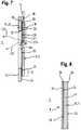
- FIG. 1a dishwashing machine 1 with a washing container 3 is shown schematically slightly in perspective in front view, in which a washing compartment 5 bounded by the washing container 3 and by a door 11 is present.
- FIG. 2shows the rinse tank 3 slightly perspective view from its rear side.
- a dishwasheris often designed as a built-in device, and is then surrounded in the installed state on the outside of furniture walls, with an outer housing can be partially or completely eliminated. Otherwise, it can expediently have a housing 13 formed by outer walls 13, which surrounds the washing container 3.
- the washing compartment 3here has a front loading opening 6 closable by a front door 11 and a total of five walls 7, namely a ceiling wall 7a, two side walls 7b, a bottom wall 7c and a rear wall 7d, at least one of these walls, in particular the rear wall 7d, which is referred to by way of example below, is replaced by two light-emitting surface elements 8 to at least 20%.
- the luminous surface elementseach cover one of two openings 23 present in the rear wall 7d (in FIG Fig. 2 shown with dashed lines), wherein the openings of a stiffening web 9 are separated from each other.
- the luminous surface elements 8preferably replace at least 50%, in particular at least 75%, preferably between 80% and 95%, of the surface of at least one wall, in particular of the rear wall 7d.
- a surface replacement of 95%takes the stiffening web 9 at least a portion of the remaining remaining area of 5%.
- Each luminous surface element 8thus forms a large-area illumination unit or light design unit, which bright the respective replaced wall surface towards the other walls such as 7a, 7b, 7c shine.
- itmay in particular be designed as a backlight, preferably uniformly radiating, or as a diffuse luminous emitter.
- itis designed as a planar surface plate, plane-surface panel or plane-surface film, so that it is good for replacing a wall or a wall part. In this case, it preferably has a rectangular shape (viewed in plan view).
- the stiffening web 9 extending in the vertical or vertical directionalso runs centrally between the two apertures covered or closed by luminous surface elements.
- the stiffening webincreases the stability of the washing container. But it also serves as a mounting bar, can be mounted on the components, for example, a fixed in the washing chamber 5 on the rear wall 7d and vertically extending feed line 12 for supplying washing liquid to a spray arm ( Figure 4 ).
- the outer side 4 of the stiffening web 9 facing away from the flushing space 5can likewise be used to assemble components, for example hoses or lines (not shown), which likewise serve to supply flushing fluid to a spray arm.
- a side wall 7bis in Fig. 2 a further situation indicated, in addition to or independent of the above-explained vertical arrangement of the two openings 23 in the rear wall 7d with the existing between them vertical stiffening web 9 of the stiffening web 9 'and the openings 23' in the depth direction of the washing container 3 and horizontally.
- the stiffening webcan be used in this case to fix on its inside guide means, in particular guide slots for a movable in the depth direction receiving basket (not shown).
- a luminous surface elementcan shine or emit light
- itis expediently designed as a light-conducting or light-guiding light guide.
- light rays that are in the luminous surface elementfor example, from a light source arranged outside the washing, such as 14 (see, eg FIG. 3, 4 ) coupled be produced in the material of the luminous element by energetic excitation, in this propagating and at a plurality of decoupling points, in particular transversely to their direction of propagation, from the interior of the rinsing container facing inner wall of the luminous surface element are coupled into the interior of the washing.
- the luminous surface element 8has a flat support plate made of a light-conducting or light-guiding material such as glass, transparent or translucent plastic such as acrylic or a composite of the two materials. It comprises extractors for coupling out light from the light-guiding or photoconductive carrier plate.
- the light decouplingcan be achieved by means of reflecting and / or scattering structures distributed in the optical waveguide material of the flat carrier plate, for example FP (see, for example, FIG. 8 ), by targeted, fine surface structures on the washing compartment facing inner wall surface of the light-guiding or photoconductive support plate, and / or by fine, on the washing compartment facing inner wall surface of the light-guiding or photoconductive support plate applied, in particular printed, patterns such as color particles can be realized.
- the inhomogeneous or heterogeneous distribution of the coupling-out structurescauses a substantially uniform illumination of the surface of the luminous surface element is achieved, since light rays from the photoconductive or light-guiding support plate is scattered scattered in all directions in the interior of the washing compartment.
- the light-emitting elementis designed as a light guide such that light, the z. B. is emitted by one or more point or rod-shaped light sources, which is preferably arranged outside the washing compartment or are distributed as evenly as possible over the surface of the light-emitting element in order to provide a backlight, ie a "backlight" can.
- Thisis referred to in particular as a light guide or light pipe.
- light such as 38, for example, at an end face such as 39 of the light-emitting element such as 8are fed (see FIG. 3 ).
- light in the light-guiding material of the luminous surface element 8 on the rear side, ie facing away from the washing compartment 5 outer wall surfacesuch.
- the flat, designed as a light guide plate luminous surface element 8is preferably made of glass or of a transparent or translucent plastic such as acrylic glass. This contains eg Extractors that decouple the light from the light guide into the washing compartment 5.
- the decouplingcan be realized by scattering and / or reflecting structures distributed in the optical waveguide material, by specific fine surface structures, and / or by fine, in particular imprinted patterns, for example in the form of a color layer or another scattering and / or reflection layer.
- light from one or more light sourcescan advantageously be coupled in at several points of the luminous surface element, such as at several end faces, in particular at two, three or all four end faces of the approximately rectangular plate of the luminous surface element. Additionally or independently thereof, light can also be fed to the light-conducting or light-conducting material of the luminous surface element at the rear outer wall surface of the luminous surface element at a plurality of locations distributed over the outer wall surface.
- the luminous surface element 8is preferably designed to be light-conducting and / or light-emitting such that one or more light beams 38, 45 (see FIG Figures 3 . 7 . 5 ) at least one arranged outside the washing compartment 5 light source 14, 40 in the luminous element 8 at at least one Einkoppelstelle 39, 24 are coupled, one or more coupled light beams such as LS1 '(see FIG. 7 ) in the luminous element 8, starting from their respective Einkoppelstelle 39, 24 away with a parallel to the washing compartment 5 facing inner wall surface 29 of the luminous element 8 extending propagation direction EFR (see FIG.
- the luminous surface element 8 viewed from the washing compartment 5is formed largely opaque.
- the respective luminous surface element 8 viewed from the dishwashing space sideis milky or otherwise diffusely luminous.
- the other wallssuch as e.g. 7a, 7b, 7c of a washing container as conventionally made of an opaque material, such as e.g. Made of metal and / or opaque plastic.
- a planar illuminating element or a luminous surface elementsuch as e.g. those which are designed as light boxes.
- the light sourcesare located in a shallow trough, which diffusely reflects the light in its interior and allows it to escape only towards the open side, ie here in the direction of the washing compartment 5.
- specially shaped reflectorsare used for fluorescent lamps as light sources and diffuser lenses for LEDs, so that the light emerging from the light trough is approximately homogeneous despite a small overall depth of the backlight.
- the light distributed by the flat plate-shaped optical waveguide or the light troughmay still have a spatial structure, it may possibly be advantageous if it is distributed uniformly by means of at least one diffuser so that it comes close to an absolutely uniform, in particular white, luminous surface.
- a simple solutionis, for example, an opal scattering plate between the light guide or light trough and the washing compartment 5 facing inner wall surface 29 of the luminous element 8.
- filmscan be used that homogenize the light more efficient than is possible, for example, with opal glass.
- At least one light source 14such as a light bulb or light emitting diode in the luminous element 8
- lightis forwarded within this and finally emitted into the interior of the washing compartment 3.
- a luminous surface element 8is fixed with its outer edge region 15, for example, to the other, adjacent, for example made of sheet metal walls 7a - 7c, for which there are a number of different possibilities.
- a luminous surface element 8is fixed to a fixing flange 16, which delimits an opening 23 in a wall 7 of the washing container 3.
- the luminous surface element 8is fixed to a mounting surface 17 of the Fixierflansches 16, which is formed either from the inside or from the outside of the Fixierflansches 16.
- the clear width the preferably rectangular opening 23is viewed in the height direction only slightly smaller than the distance between the bottom wall 7c and ceiling wall 7a and viewed in the width direction only slightly smaller than half the distance between the two side walls 7b.
- the fixing flange 16can be formed by a 90 ° flanging inwards to the respective opening 23 in the rear wall 7c towards the rear end-side edge regions of the cover wall 7a, the side walls 7b and the bottom wall 7c. However, the fixing flange 16 can also be the remainder of a wall 7, which remains standing after the production of a breakthrough 23 by means of a punching.
- the fixation of the large-area luminous surface element 8 on the fixing flange 16can take place, for example, with the aid of an adhesive layer 21, which also ensures a sealing of an existing between the mounting surface 17 and the luminous surface element 8 parting line 19, so that no rinsing liquid between the Fixierflansch 16 and the luminous element 8 after can step outside.
- an adhesive layer 21which also ensures a sealing of an existing between the mounting surface 17 and the luminous surface element 8 parting line 19, so that no rinsing liquid between the Fixierflansch 16 and the luminous element 8 after can step outside.
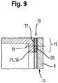
- FIG. 9an additional or alternative fixation is shown, namely via a screw connection between the outer edge region 15 of the plate-shaped, in particular rectangular luminous surface element 8 and the fixing flange 16.
- the screwis in Fig. 9 indicated by a dashed line 18.
- a seal 20is arranged for example of an elastomeric material.
- the luminous sheetmay be attached to the inside or as shown in FIG Fig.
- the luminous surface element 9is dimensioned so that it surrounds the opening 23 framing edge 25 of the wall 7d and the Fixierflansch 16 on the outside, that overlaps on the side facing away from the washing compartment 5.
- the fixation of the luminous surface element 8 on the fixing flange 16 of the rear wall 7dcan in turn be done in different ways, for example by means of an adhesive layer 28, which also performs a seal in the overlap region 27 between the edge 25 and the luminous element 8 existing parting line 26.
- the fixationcan continue additionally or alternatively by a screw, indicated by the dot-dash line 18, take place.
- an adhesive layer 28can also be a circumferential seal, corresponding to the seal 20 in Fig. 9 , be provided.
- the respective luminous surface element 8can in particular be designed such that the light emitted by it into the flushing chamber has a different color than the coupled-in light of the light source 14. This can be made possible, for example, by the fact that the material of the luminous surface element 8 dyes FP or other litter Contains - and / or reflection particles. It is also conceivable that, in addition or as an alternative, a color layer 36 or other particle layer, for example in the form of a colored plastic film or the like. attached to the inside or inside wall surface 29 and / or the outside or outside wall surface 24 of the luminous surface element 8, 9, is glued approximately ( Fig. 8 ).
- luminescent dyescan also be used as dyes. Another embodiment is to form the wanderabilityde luminous surface element 8 as a light guide, in particular, together with a luminescent dye contained in the material of the luminous element 8 further optical design options arise.
- the light-emitting surface element 8can be located on the inside, i. on the side facing the washing compartment 5 with a protective layer 37 of a from the inside of the luminescent surface element 8, 9 outwardly towards the washing compartment 5 translucent material, for example, be provided with a paint or a plastic film that from the outside, in particular from the washing compartment 5 forth largely opaque, especially opaque.
- the protective layer 37is braded either directly on the inner wall of the light-conducting carrier plate of the luminous surface element facing the washing compartment. If a color layer 36 is present on the interior wall surface 29 facing the dishwashing space, the protective layer is applied thereon as the topmost finishing layer, as shown in FIG Fig. 8 is shown.
- the emission of light into the washing compartment 5can be enhanced by providing the luminous surface element 8 on the outside, ie on the outer wall surface 24 facing away from the washing compartment 5, with a layer reflecting light rays toward the washing compartment 5.
- the coupling of lightcan in principle be such that the light source 14 at a distance, that is, while leaving an air gap to the luminous element 8 is arranged.
- the light source 14can then be configured in particular such that its light cone 38 completely loads the outer wall surface 24 of the luminous surface element 8.
- a plurality of light sources 14may be provided offset from one another in such a way that their light cones cover different areas of the outer wall surface 24 of a luminous surface element 8 or, as shown in FIG Fig. 4 the case is, in each case a luminous surface element 8 is associated with at least one light source.
- an arrangement of a light source 14is also conceivable such that its light cone 38 acts on the end face 39 of the light-emitting surface element 8 ( Fig. 3 ). Possibly. can also be provided on several end faces of the luminous element 8, one or more light sources for the frontal coupling of light.
- an optical transmission element 40may be provided for coupling in the light. This is formed, for example, from one or more optical waveguides, for example glass fibers, and is coupled on the one hand to the light source 14 and on the other hand to an outer wall surface 24 or an end face 39 of the luminous surface element 8.
- the optical coupling between the transmission element 40 and the light-emitting surface element 8can take place without contact, in particular with the interposition of an optical or imaging unit.
- a distance 44 or a free air gapis then present.
- a light cone 45is formed (see Fig. 5 ).
- the optical couplingcan also be direct, ie the light exit surface 43 of the transmission element 40 is in mechanical connection with the light-emitting surface element 8.
- the light exit surface 43may be preceded by an optical deflection element 46 or an optical imaging system.
- Fig. 3a case is shown in which a plurality of transmission elements 40a, 40b are optically coupled to a light source 14, the light exit surfaces 43 are arranged at different positions of the outer wall surface 24 of the luminous element 8.
- Fig. 10shows as a detail the rear wall 7d of a washing container 3. This is preferably integral with the example deep-drawn washing container 3 (in Fig. 10 not shown).
- two window-like apertures 23are present, which are substantially rectangular and extend substantially vertically over almost the entire height of the washing container 3 or the rear wall 7d.
- the preferably produced by a punching process openings 23are bounded by an edge of the rear wall 7d, which forms a Fixierflansch 16 in particular for fixing a luminous element 8.
- the apertures 23are separated from one another by a stiffening web 9, wherein this, like the apertures 23, also extends in the vertical direction of the washing container 3.
- the reduced due to the replacement of a majority of the rear wall 7d by a luminous region mechanical stability of the washing container 3is also increased by the fact that the luminous region is realized by two by a stiffening web separate openings 23 or this overlapping or occluding luminous surface elements 8 in that the fixing flange 16 is offset in the transverse direction 58 of the wall relative to the plane 47 which is spanned by the stiffening web.
- the stiffening web 9is thus seen in cross-section the shape of a C-profile, which in particular significantly increases its buckling and torsional rigidity.
- the openings bounding wall portionsare formed due to the offset in question in the manner of angle profiles or stepped, which further increases the mechanical stability of the rear wall.
- the offset of the Fixierflansches 16can be produced in a simple manner by a recess 48 is impressed from the inside or outside thereof in the rear wall 7 d (or another wall of the washing container) and then a region of the recess 48 corresponding to the opening 23 is punched out.
- the fixing flange 16is offset towards the washing compartment 5, ie the depression 48 has been pressed from the outside of the rear wall 7d in the direction of the washing compartment.
- a luminous surface element 8can be attached to the outside of the fixing flange 16 pointing away from the washing compartment 5, with part of its thickness being received by the depression or recess 48, ie the luminous surface element 8 is not or only partly over that of the recess Stiffening bar spanned level 47 addition. This is advantageous if the space at the Spül relierland.
- a luminous surface element 8can be designed in such a way that, in addition to its lighting function, it fulfills further functions, such as increasing the rigidity and mechanical strength of the respective wall or being resistant to the conditions prevailing in the washing compartment during the cleaning operation.
- the disadvantage hereis that such additional functions are often not given in commercially available light-emitting elements, so that special developments are required.
- requirements exceeding the luminous functionare preferably realized with the aid of at least one transparent, translucent or reflective surface element FE arranged on one side of the luminous surface element 8 and covering the opening.
- the respective surface element FEis not connected over a large area, for example, in the manner of a lamination with the luminous surface element.
- the luminous surface element and the respective surface element FE associated with itare separated from each other by an air gap 49a, 49b.
- the gap width of the air gap 49a, 49bis greater than 1 ⁇ m. The occurrence of disturbing light-dark zones due to interference phenomena, so-called Newtonian rings, is thereby prevented.
- the air gap 49a, 49bcan also be used for thermal insulation. Air present in the air gap 49a, 49b can act as an insulator. If the gap width of the air gap 49a, 49b is limited to a maximum of 2 cm, the formation of air convection, which would reduce the insulating effect of the air cushion in the air gap, can be prevented.
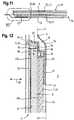
- each luminous surface element 8is assigned a surface element FE in the form of a front plate 50 and / or on its side facing away from the washing area a reflective surface element FE in the form of a reflector film 53, leaving an air gap 49a, 49b free.
- the gap width of the air gap 49ais 0.5 mm and the gap width of the air gap 49b is 0.1 mm.
- the header plate 50has a thickness of about 2 mm and is made of a plastic which is resistant to the chemicals used during operation in the washing compartment, for example of PMMA or polyamide.
- the reflector sheet 53has, as Fig. 14 can be seen, preferably a multilayer structure.
- the base film 52made of transparent or translucent material, for example of a polyacrylate, whose side facing away from the washing compartment 5 is provided with a reflector film 54 whose reflective property, for example, on a coating with white paint, for example with TiO 2 , or due to a metallization.
- the lightis coupled into the luminous surface element 8 via one of its end faces 84.
- the corresponding light source 14, preferably an LED strip 55 positioned on the front side on the luminous surface element 8,is dimensioned or oriented in such a way that the light radiated from it does not reach the front side only the luminous surface element 8, but at the same time via an end face 85 of the reflector film 53 in this, ie mainly in the base film 52, is coupled.
- the side facing the flushing space 5is provided with at least one diffuser layer 56, that is to say a light-scattering film or pane.
- the above-described effect of a uniform illumination Spülraums 5is further enhanced in this way.
- the aperture covering surface element FEsuch as a front plate 50
- the fixing flange 16are various options into consideration.
- a fixationis preferably such that a relative movement between the luminous surface element 8 and / or the surface element and the fixing flange 16, which is based on different thermal expansions and extends parallel to the plane 62 spanned by the fixing flange 16, is compensated.
- thisis accomplished in that the luminous surface element 8 and / or the surface element FE, in particular the above-mentioned header plate 50 with the interposition of an elastic, by the relative movement in question caused shear forces Leveling layer 57 adhesively connected to the fixing flange 16.
- the compensating layer 57which is preferably configured in the form of an O-ring, may be provided or provided with adhesive, for example an acrylic adhesive, on its side facing the fixing flange 16 and facing away from its fixing flange 16, that is to say in the manner of a double-sided adhesive tape be educated.
- the shear forces absorbing effect of the compensating layer 57is particularly well pronounced when this is at least partially, preferably completely formed by a plastic foam, in particular a polyolefin foam, since the cellular space structure of the foam allows particularly high absorption of shear forces.
- a certain minimum thickness of the leveling layer of 0.2 mm to 0.4 mmis required.
- the maximum thickness of the compensation layershould expediently not exceed 2 mm, more preferably 1 mm.
- the attachment plate 50may be made of a relatively stable material so that it can contribute to the stability of a wall 7 at least partially replaced by a lighting element 8.
- a materialis selected which is resistant to the chemicals used in the dishwasher during operation of the dishwasher.
- the choice of the luminous surface element 8 itselfcan then be made exclusively according to optical or lighting-technical aspects, without regard to mechanical or chemical properties or requirements.
- the attachment plate 50is made with the aid of a connecting element V, which is preferably connected to the carrier T by means of a positive engagement with the wall 7d in the transverse direction 58.
- a connecting element Vis particularly advantageous in terms of assembly technology, since it can be configured for example as a snap connection, which only requires a simple linear joining movement during assembly.
- a defined air gap 49a, 49b between the elements in questioncan be maintained by a form-fitting connection, in particular on assembly technology simple manner.
- a luminous surface element 8 or a surface element FEfor example a reflector film 53
- an effective in the transverse direction wall 58 positive connectionwhich is in particular realized by one or more snap connections.
- luminous surface elements 8 and / or surface elements FEcan be connected with a simple linear joining movement with the connecting element V, which is already fixed on the support T, for example.
- the connecting element Vis preferably a frame 59, which on the one hand the carrier T, so about the attachment plate 50, and on the other hand other planar elements, preferably a luminous surface element 8 and / or one or more surface elements FE, surrounds and said elements together with a force acting in the transverse direction of the wall 58 form fit together.
- the frame 59engages behind the handle elements 60, the washing compartment 5 facing side 63 of the carrier T and the attachment plate 50.
- the locking elements 60are tab-shaped wall portions which are parallel to the plane defined by the frame 59 Plane plane or parallel to the spanned by the stiffening web 9 Level 47 extend.
- the thickness of the compensation layer 57is selected such that a gap 64 remains free between the fixing flange 16 and the carrier T or the attachment plate 50, whose gap width measured in the transverse direction 58 of the wall is greater than the thickness 70 of the engagement elements 60 in that the elastic compensation layer 57 which is elastic in the transverse direction 58 of the wall is compressible to a certain extent during installation for the purpose of a sufficient adhesive bond between the support T and the fixing flange 16 in the transverse direction 58 of the wall, without the frame 59 coming into contact with the fixing flange 16 or the pressing of the Leveling layer 57 impeded to the fixing flange 16.
- the frame 59has a first receptacle 65, in which the carrier T or the attachment plate 50 is completely received.
- the receptacleis bounded laterally by a wall 66, which extends in the transverse direction of the wall 58 away from the rear grip elements 60.
- the pointing away from the washing compartment 5 free ends of the wall 66are at least partially formed as a rear grip elements H, which engage behind the carrier T on its side facing away from the washing compartment 5 page 68.
- the rear grip elements Hare preferably formed in the form of circumferentially of the frame 59 distributed hook strips 67.
- the frame 59has a further receptacle 73 which serves for preferably complete reception of the luminous surface element 8.
- the the washing compartment 5 opposite side of the rear grip elements Hdefines a support plane 74, on which the luminous surface element 8 is applied.
- the frame 59is essentially formed by a wall 76 having a step 76, wherein the surface of the step 76 facing away from the washing chamber 5 extends in the support plane 74. In the assembled state, therefore, the luminous surface element 8 rests on the catch elements H and on the step 76.
- the dimension of the engagement elements H in the transverse direction 58 of the walldefines the gap width of the gap 49a present between the luminous element 8 and the carrier T or the attachment plate 50.
- a wall portion 77 of the wall 75 extending from the step 76 in the direction of the washing compartment 5surrounds the wall 66 having the rear grip elements H with a lateral spacing 78.
- the free end of the wall section 77 facing the washing compartment 5is formed with a wall 81 running parallel to the support plane 74. from which the wall 66 extends toward the receptacle 73 away.
- Free ends of the stepped wall 75are grasping elements H'angeformt which engage behind the flushing chamber 5 side 79 of the luminous surface element 8 at least indirectly.
- the rear grip elements H 'which are preferably designed as hook strips 80 distributed in the circumferential direction of the frame 59, act directly on the side 61 of the luminous surface element facing away from the washing compartment 5.
- a surface element FEin particular the above-mentioned reflector film 53 is arranged.
- the air gap 49bis defined by marginal spacers (not shown). The rear grip elements H 'engage behind the reflector film 53, thus lie against this.
- the hook strips 80are also formed on their side facing away from the washing compartment 5 with a run-on bevel 71 facilitating the introduction of the optionally provided with a reflector sheet 53 luminous surface element 8 in the joining direction 72.
- the catch elements H'may act like snap-in connection elements or are designed as such.
- the light-emitting surface element 8is assigned a light source 14 in the form of an LED strip 55, this being arranged in a receptacle 83 which opens to the flushing space 5.
- the light source 14 or the LED strip 55is dimensioned and arranged such that light emanating from it is directed both into the end face 84 facing it of the luminous surface element 8 as well as in its facing end 85 of the reflector sheet 53 is coupled, which is indicated by the arrows 86 in Fig. 12 is indicated.
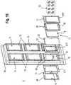
- FIG. 15schematically shows a perspective view of another advantageous embodiment of an illuminated wall, which limits the washing compartment, in particular the rear wall of the washing container of the dishwasher of FIG. 1 and viewed from the outside, wherein additionally exemplified the individual components of a single illumination field of the wall are shown in an exploded view.
- the rear wall 7dtwo vertical rows of three superposed openings 23 are provided side by side, ie a total of 6 openings in the rear wall 7d are present.
- the respective opening 23is rectangular.
- vertical and horizontal stiffening webs of the preferably metallic wall 7dhave stopped, so that their rigidity is sufficiently ensured despite the openings.
- the illumination element ILcomprises, as seen from the interior of the washing compartment 5, the flushing-resistant cover plate 50 which is on the rear side, ie the outside of the wall 7d, by means of a frame-shaped adhesive mask 572 glued.
- the adhesive maskrests on a fixing flange 16 of the wall 7d extending around the aperture 23. This is preferably formed trough-shaped recessed towards the washing compartment and takes the attachment plate 50, in particular largely flush, on.
- the intent plate 50is thus fixed by means of the adhesive mask 572 on the opening 23 encircling edge of the wall 7d.
- the adhesive mask 572at the same time forms a liquid-tight seal between the attachment plate 50 and the edge zone 16 of the rear wall 7d around the aperture 23.
- itserves as a compensation layer for receiving shear forces, which may occur through different thermal expansions of the rear wall 7d and the attachment plate 50.
- Such different thermal expansionsmay be due to different materials for the rear wall 7d such as steel and the header plate 50 such as plastic, as they have different thermal expansion coefficients.
- the illumination element ILhas behind the front plate 50 (viewed from inside to outside) the light-emitting element or light panel 8.
- the luminous surface element 8is mounted on the front side in a cover frame serving as a holding element HE.
- the holding element HEhas a closed rear wall RE, which is designed as a reflector surface element.
- the rear wall of the holding element HE on its side facing the light panel 8may be provided with a white color layer or a white coating as a light-reflecting background.
- the cover frame HEalso takes at the same time a light strip such.
- LED strip LL or other elongated light sourcesuch that light can be coupled along the longitudinal extension of an end face in this, in particular in the upper end side of the here in the embodiment rectangular light panel 8.
- the light panel 8is expediently supported in the cover frame HE in such a way that an air gap of predetermined gap width is present between it and the light-reflecting rear wall RE, in order to prevent unwanted luminous phenomena, such as, for example, To avoid Newton's rings and to ensure a largely homogeneous, with respect to the total area of the light panel 8, uniform illumination. At each local point of the light panel 8, this therefore preferably illuminates approximately with the same luminosity.
- the cover frame HE with the light panel 8 held by itadvantageously by means of a mechanical attachment to the outside of the rear wall 7d viewed from the inside out behind the attachment plate 50, which covers the opening 23 by means of the adhesive mask 572 liquid-tight or closes, with a predetermined gap distance staggered.
- the washing compartment 5 facing side of the rear wall 7dprovided a preferably rectangular frame BR, which is fixed by means of a here rectangular adhesive mask 571 on the wall edge all around the here rectangular opening 23 flushing chamber side.
- the frame BRhas on its rear side a plurality of pins, pins or bolts SI, which are passed through corresponding holes or holes BO in the rear wall 7d, the header plate 50, in the cover frame HE and in an optionally additionally present contact frame APR and by means of lock washers SS are counterclaimed on the outside of the cover HE.
- the cover frame HE with the content in it held light panel 8is thus behind in a given free space distance the attachment plate 50 fixed by a mechanical attachment to the outside of the rear wall 7d.
- the flushing space provided on the insidecan be omitted BR frame and provided for fixing adhesive mask 571.
- the mechanical fixation of components such as e.g. 50, HE of the illumination element ILcan then take place in a corresponding manner as explained above by means of a counter-holder.
- the illumination element ILBy the combination of adhesive bonding and additional mechanical attachment of the illumination element IL to the illumination wall, e.g. 7d, the overall construction of which is largely liquid-tight and largely insensitive to shocks from outside and inside.
- the mechanical attachment of the illumination element on the wallprovides relief of the sealing adhesive connection between the attachment plate 50 and the support zone, in particular the fixing flange 16, which surrounds the respective opening 23.
- the cover frame HEcan be designed in particular such that it is arranged in a defined free space distance in front of the light panel 8, i. before the washing room facing side, and the lye-stable attachment plate 50 receives and holds.
- the adhesive connection 572is provided between the washing compartment facing outer edge of the attachment plate 50 and the support zone 16 and the illumination element IL additionally fixed to the outside of the wall by means of a suitable mechanical attachment.
- This overall structure of the illumination element ILwhich according to an advantageous embodiment variant (viewed from the inside outwards) comprises the cover frame HE, the attachment plate 50, the light panel 8 behind it with predetermined gap spacing, and the reflector surface element RE behind this with predetermined gap distance, can, if necessary, according to an advantageous alternative ., Only by means of the adhesive mask 572 on which the breakthrough 23 enclosing all around, rear fixing edge, in particular Fixierflansch 16 of the rear wall 7 d of the washing container to be fixed. An additional mechanical attachment is therefore missing in this variant.
- the respective wall provided for the illuminationwhich delimits the dishwashing space becoming wet in the dishwashing mode, has a multiplicity of illumination elements which cover or close the associated apertures in the wall.
- the openingsremain separated by remaining webs of wall material such as steel sheet.
Landscapes
- Physics & Mathematics (AREA)
- Engineering & Computer Science (AREA)
- General Engineering & Computer Science (AREA)
- General Physics & Mathematics (AREA)
- Optics & Photonics (AREA)
- Washing And Drying Of Tableware (AREA)
- Electroluminescent Light Sources (AREA)
Description
Translated fromGermanDie Erfindung betrifft eine Geschirrspülmaschine mit einem von einem Spülbehälter umschlossenen Spülraum, in dem Spülgut vorzugsweise bei erhöhter Temperatur und unter Einsatz von, insbesondere mit Chemikalien wie z.B. Reinigungsmittel oder Klarspülmittel versetzter, Spülflüssigkeit, bevorzugt Wasser gereinigt wird. Allgemein herrschen in einem Spülraum Bedingungen vor, die von jenen der normalen Umgebung hinsichtlich, Temperatur, Feuchtigkeit, etc. teils erheblich abweichen. Im Spülbetrieb der Geschirrspülmaschine, während dem die Beladeöffnung deren Spülbehälters zweckmäßigerweise durch eine Tür geschlossen ist, wird im Spülraums Spülflüssigkeit mittels ein oder mehrerer Sprüheinrichtungen versprüht. Der Spülraum wird dabei also nass. Im Spülraum sind vorzugsweise ein oder mehrere Beladeeinheiten wie z.B. Geschirrkörbe und/oder Besteckschubladen untergebracht, die der Aufnahme von zu reinigendem Spülgut dienen.The invention relates to a dishwasher with a washing compartment enclosed by a washing container in which items to be washed preferably at elevated temperature and using, in particular with chemicals such. Cleaning agent or rinse aid offset, rinsing liquid, preferably water is purified. Generally prevail in a flushing room conditions that differ from those of the normal environment in terms of, temperature, humidity, etc. in some cases significantly. In the dishwashing operation of the dishwasher, during which the loading opening of the washing container is expediently closed by a door, washing liquid is sprayed in the washing compartment by means of one or more spraying devices. The dishwasher is getting so wet. In the washing compartment are preferably one or more loading units such as e.g. Crockery baskets and / or cutlery drawers housed, which serve to receive items to be cleaned.
Um die Beleuchtungsverhältnisse zu verbessern, ist vielfach ein elektrisches Leuchtmittel im Spülraum vorgesehen, was aber zum einen eine Abschirmung gegenüber den im Spülraum herrschenden Bedingungen und außerdem eine Durchführung von ein oder mehreren elektrischen Stromleitungen durch eine den Spülraum begrenzende Wand erforderlich macht. Nachteilig ist auch, dass solche Leuchtmittel oftmals störend sind, weil sie den Nutzraum des Spülraums verringern und nur eine unzureichende Ausleuchtung des Spülraums bewirken. Außerdem können die Leuchtmittel vielfach nur so positioniert werden, dass sie den Benutzer blenden, wenn dieser den Spülraum be- oder entlädt.In order to improve the lighting conditions, an electric light source is often provided in the washing compartment, but on the one hand makes a shield against the conditions prevailing in the washing compartment conditions and also a passage of one or more electrical power lines through a wall bounding the washing room. Another disadvantage is that such bulbs are often disturbing because they reduce the useful space of the washing and cause only insufficient illumination of the washing compartment. In addition, the bulbs can often only be positioned so that they dazzle the user when loading or unloading the flushing chamber.
Die Geschirrspülmaschine der
Aufgabe der Erfindung ist es, eine Geschirrspülmaschine mit einer verbesserten Beleuchtung bzw. Illuminierung deren Spülraums bereitzustellen.The object of the invention is to provide a dishwasher with an improved lighting or illumination of the washing compartment.
Diese Aufgabe wird gemäß den Merkmalen des Anspruchs 1 gelöst. Dabei weist mindestens eine der Wände des Spülraums, insbesondere dessen Rückwand, zumindest zwei jeweils von einem Leuchtflächenelement überdeckte oder verschlossene Durchbrüche bzw. Durchbrechungen und einen die Durchbrüche voneinander trennenden Versteifungssteg auf, wobei die Leuchtflächenelemente jeweils eine Gesamtfläche aufweisen, die mindestens 20 %, insbesondere zwischen 50% und 95%, der Wandfläche entspricht.This object is achieved according to the features of
Durch diese Ausgestaltung wird eine großflächige, d.h. ausgedehnte Illuminationsregion bereitgestellt, die gegenüber einer bisherigen, punktförmig ausgebildeten Lichtquelle, die zusätzlich auf einer Seitenwand des Spülraums in diesen abstehend angebracht ist, eine verbesserte, insbesondere eine blendfreie, wenig Schattenwurf erzeugende und gleichmäßige Ausleuchtung des Spülraums, aber auch zusätzlich oder unabhängig hiervon eine Vielzahl von Illuminationswirkungen, Lichtdesigns bzw. Lichtgestaltungen ermöglicht. Gleichzeitig wird vermieden, dass das gegebene Raumvolumen des Spülraums wie bisher durch das in den Spülraum vorstehende Gehäuse einer punktuellen, an eine Seitenwand des Spülraums angebrachten Lichtquelle gestört, insbesondere verkleinert, wird.By this configuration, a large area, i. extended Illuminationsregion provided, compared to a previous, point-shaped light source, which is additionally mounted on a side wall of the washing compartment in this projecting, an improved, in particular a glare-free, little shadow-generating and uniform illumination of the sink, but also in addition or independently thereof a variety Illumination effects, lighting designs or lighting designs allows. At the same time, it is avoided that the given volume of space of the washing compartment, as hitherto, is disturbed, in particular reduced, by the housing projecting into the washing space of a punctual light source attached to a side wall of the washing space.
Zu den Wänden des Spülraums zählt im Rahmen der Erfindung insbesondere auch die Innenwand der Tür, die in deren Schließendstellung dem Spülraum zugewandt ist. Auch diese Türinnenwand kann nach dem erfindungsgemäßen Konstruktionsprinzip insgesamt oder teilweise als Leuchtflächenelement ausgebildet sein. Somit ist der Spülraum der im Spülbetrieb durch Spülflüssigkeit nass werdende Behandlungsraum der Geschirrspülmaschine, in dem zu reinigendes Spülgut zur Beaufschlagung mit Spülflüssigkeit unterbringbar ist. Der Spülraum ist von Wänden des Spülbehälters und der Innenwand, d.h. der sogenannten Innentür der Tür, vorzugsweise weitgehend flüssigkeitsdicht, umschlossen, wenn die Tür die Beladeöffnung des Spülbehälters, insbesondere z.B. für den Spülbetrieb der Geschirrspülmaschine, verschließt.In the context of the invention, the walls of the washing compartment also include, in particular, the inner wall of the door, which faces the washing space in its closing end position. These door inner wall can be formed according to the construction principle of the invention in whole or in part as a luminous surface element. Thus, the rinsing chamber is the treatment room of the dishwasher which becomes wet during rinsing operation by rinsing liquid, in which items to be cleaned can be accommodated for rinsing liquid to be rinsed. The washing compartment is separate from walls of the washing compartment and the inner wall, i. the so-called inner door of the door, preferably substantially liquid-tight, enclosed, when the door, the loading opening of the washing compartment, in particular, for. for the washing operation of the dishwasher, closes.
Eine Wand kann auf die vorgeschlagene Weise nahezu vollständig als Leuchtregion gestaltet werden, wobei jedoch stets zwischen den zwei Leuchtelementen der Versteifungssteg, der vorzugsweise einstückig mit dem Spülbehälter bzw. der Wand ausgebildet ist, vorhanden ist und eine Aussteifung des jeweiligen Wandbereichs bzw. des Spülbehälters nach Art einer Fachwerkkonstruktion gewährleistet, so dass ein gegebenenfalls von den beispielsweise plattenförmig ausgebildeten Leuchtflächenelementen zu leistender Beitrag zur Stabilität des Spülbehälters reduziert werden kann. Außerdem ist auch bei einem weitgehenden Ersatz der Wand durch Leuchtflächenelemente auf konstruktiv einfache Weise und ohne Einschränkung des Platzangebots im Spülraum dessen Illumination sichergestellt. Mit Hilfe der in Rede stehenden großflächigen Leuchtregion lässt sich, wenn diese besonders bevorzugt an der Rückwand vorgesehen ist, vor allem der hintere, von der frontseitigen Tür abgewandte, bisher meist im Dunkeln liegende Bereich des Spülraums ausreichend ausleuchten. Dies verbessert die Ergonomie und den Komfort für einen Nutzer des Haushaltsgeräts.A wall can be designed in the proposed manner almost completely as a luminous region, but always between the two luminous elements of the stiffening web, which is preferably formed integrally with the washing or the wall, is present and a stiffening of the respective wall area or the Spülbehälters guaranteed in the manner of a truss structure, so that an optionally be made of the example plate-shaped luminous surface elements contribution to the stability of the washing container can be reduced. In addition, even with a substantial replacement of the wall by illuminated surface elements in a structurally simple manner and without limiting the space in the washing room its illumination ensured. With the help of the large-area luminous region in question can be, if this is particularly preferably provided on the rear wall, especially the rear, facing away from the front door, hitherto mostly lying in the dark area of the washing compartment sufficiently illuminate. This improves the ergonomics and comfort for a user of the household appliance.
Der von den Leuchtelementen flankierte Versteifungssteg hat neben seinem stabilisierenden Einfluss den Vorteil, dass er eine Montagefläche für innerhalb des Spülraums vorgesehene Funktionselemente bietet. So kann ein an der Rückwand vertikal verlaufender Versteifungssteg beispielsweise zum Anbringen einer oder mehrerer Leitungen zur Wasserzufuhr zu einer an der Deckenwand angeordneten Sprüheinrichtung, insbesondere zu einer dort vorgesehenen Dachbrause oder einem dort rotierbar angebrachten Sprüharm, und/oder zu einer an der Rückwand optional zu montierenden Sprüheinrichtung, insbesondere zu einem dort rotierbar angebrachten Sprüharm dienen. Die dem Spülraum abgewandte Seite des Versteifungsstegs lässt sich ebenfalls zur Montage von Bauteilen, beispielsweise ebenfalls einer Zuführleitung für einen Sprüharm oder von Schläuchen nutzen.The stiffening web flanked by the luminous elements, in addition to its stabilizing influence, has the advantage of providing a mounting surface for functional elements provided within the flushing chamber. Thus, a stiffening web extending vertically on the rear wall can be used, for example, for attaching one or more lines for supplying water to a spraying device arranged on the ceiling wall, in particular to a roof shower provided there or a spray arm mounted rotatably there, and / or to an optionally mounted on the rear wall Spray device, in particular to serve there rotatably mounted spray arm. The side facing away from the washing compartment of the stiffening web can also be used for the assembly of components, for example, also a supply line for a spray arm or hoses.
Mit anderen Worten und verallgemeinernd ausgedrückt weist eine erfindungsgemäße Geschirrspülmaschine einen im Spülbetrieb flüssigkeitsbeaufschlagten Spülraum auf, der von mehreren Wänden eines Spülbehälters und von der Innenwand einer Tür umgrenzt ist. Wenigstens zwei Durchbrüche in mindestens einer der Wände, insbesondere in der Rückwand, des Spülbehälters, sind jeweils von wenigstens einem Illuminationselement überdeckt oder verschlossen, das mindestens ein Leuchtflächenelement und wenigstens ein diesem beigeordnetes transparentes, transluzentes oder reflektierendes Flächenelement umfasst.In other words and in general terms, a dishwasher according to the invention has a rinsing chamber which is filled with liquid during the rinsing operation and which is delimited by a plurality of walls of a rinsing container and by the inner wall of a door. At least two apertures in at least one of the walls, in particular in the rear wall of the washing container, are each covered or closed by at least one illumination element which comprises at least one luminous surface element and at least one transparent, translucent or reflective surface element attached thereto.
Ein Leuchtflächenelement lässt sich zwar prinzipiell so gestalten, dass es neben seiner Leuchtfunktion weitere Funktionen erfüllt, beispielsweise die Steifigkeit und mechanische Festigkeit der jeweiligen Wand erhöht, resistent gegenüber den während des Reinigungsbetriebs bzw. Spülbetriebs im Spülraum herrschenden Bedingungen ist, oder reflektierende Eigenschaften aufweist, um möglichst das gesamte in ein Leuchtflächenelement eingekoppelte oder von diesem erzeugte Licht zur Ausleuchtung des Spülraums ausnutzen zu können. Eine derartige Multifunktionalität lässt sich vielfach nur mit Hilfe von marktunüblichen und daher teuren Spezialentwicklungen verwirklichen. Erfindungsgemäß wird hier der Weg beschritten, Funktionen der o.g. Art mit Hilfe wenigstens eines separaten transparenten, transluzenten oder reflektierenden Flächenelements zu verwirklichen, d.h. diese Funktionen von den Leuchtflächenelementen abzukoppeln. Auf diese Weise ist es möglich, das jeweilige Leuchtflächenelement ausschließlich hinsichtlich seiner optischen Eigenschaften auszuwählen, wobei Funktionalitäten wie etwa eine Versteifung der das Leuchtflächenelement aufweisenden Wand nicht beachtet werden müssen. So kann etwa eine Aussteifung der Wand durch eine auf der dem Spülbehälter zugewandten Seite des Leuchtflächenelements angeordnete Vorsatzplatte, wie weiter unten noch erläutert wird, verwirklicht werden.In principle, a luminous surface element can be designed in such a way that, in addition to its luminous function, it fulfills further functions, for example the rigidity and mechanical properties Increased strength of the respective wall, is resistant to the conditions prevailing during the cleaning operation or rinsing operation conditions in the washroom, or has reflective properties, as possible to exploit the entire coupled into a luminous element or generated by this light to illuminate the washing compartment. Such multi-functionality can often only be achieved with the help of market-unusual and therefore expensive special developments. According to the invention, the path is here taken to realize functions of the above-mentioned type with the aid of at least one separate transparent, translucent or reflective surface element, ie decoupling these functions from the luminous surface elements. In this way, it is possible to select the respective luminous surface element exclusively with regard to its optical properties, wherein functionalities such as a stiffening of the luminous surface element having the wall need not be considered. For example, a stiffening of the wall can be achieved by means of an attachment plate arranged on the side of the luminous surface element facing the washing container, as will be explained below.
Insbesondere kann es in Verallgemeinerung der vorstehenden spezifischen Konstruktion zweckmäßig sein, wenn die jeweilige Wand mehr als zwei Durchbrüche aufweist, die von jeweils einem Leuchtflächenelement überdeckt oder verschlossen sind. Zwischen je zwei benachbarten Durchbrüchen ist dann jeweils ein Versteifungssteg der Wand vorgesehen. Vorteilhaft kann es z.B. sein, wenn in Breitenrichtung der Wand betrachtet eine Reihe von mindestens zwei Durchbrüchen mit zugehörigen, diese überdeckenden oder verschließenden Illuminationselementen vorgesehen ist, und/oder wenn in Höhenrichtung der Wand betrachtet eine Reihe von mindestens zwei Durchbrüchen mit zugehörigen, diese überdeckenden oder verschließenden Illuminationselementen vorgesehen ist. Dies ermöglicht ein Wand- Beleuchtungsfeld, das sich aus einer Vielzahl von Durchbrüchen mit diese überdeckenden oder verschließenden Leuchtelementen zusammensetzt. Es ist aufgrund der verbleibenden Versteifungsstege zwischen je zwei Durchbrüchen der Wand ausreichend stabil und eigensteif. So kann beispielsweise ein Beleuchtungsfeld einer Wand dadurch gebildet sein, dass in Breitenrichtung der Wand nebeneinander zwei Reihen von je drei übereinander angeordneten Durchbrüchen vorgesehen sind, die jeweils mit einem Leuchtelement überdeckt oder verschlossen sind, d.h. die Wand weist insgesamt sechs Durchbrüche mit jeweils zugehörigem Leuchtelement auf.In particular, it can be expedient in generalization of the above specific construction, if the respective wall has more than two openings, which are covered or closed by a respective luminous surface element. Between each two adjacent openings then a stiffening web of the wall is then provided. It can be advantageous if viewed in the width direction of the wall, a series of at least two openings with associated, this covering or occluding Illuminationselementen is provided, and / or viewed in the height direction of the wall a number of at least two openings with associated, these covering or occluding Illuminationselementen is provided. This allows a wall illumination field, which is composed of a plurality of openings with these overlapping or occluding light elements. It is due to the remaining stiffening webs between each two openings of the wall sufficiently stable and intrinsic stiffness. Thus, for example, an illumination field of a wall can be formed by two rows of three superimposed apertures being provided in the width direction of the wall, each being covered or closed by a luminous element, ie the wall has a total of six apertures, each with a respective luminous element ,
Zur Fixierung der Leuchtflächenelemente an einer Wand und zu deren Ausgestaltung gibt es unterschiedliche konstruktive Möglichkeiten. Vorzugsweise ist vorgesehen, dass die Leuchtflächenelemente jeweils mittel- oder unmittelbar an einem die Durchbrüche umgrenzenden, einen Fixierflansch bildenden Rand einer Wand fixiert sind. Dies lässt sich auf herstellungstechnisch einfache Weise dadurch realisieren, dass in einem zunächst mit geschlossenen Wänden hergestellten Spülbehälter die Wanddurchbrüche durch einen Stanzvorgang erzeugt werden. Die stehenbleibenden Bereiche der Wand bilden dann den Versteifungssteg und die Fixierflansche.There are different constructional possibilities for fixing the luminous surface elements to a wall and for designing them. It is preferably provided that the luminous surface elements are respectively fixed directly or indirectly to a rim of a wall which bounds the apertures and forms a fixing flange. This can be realized in a manufacturing-technically simple manner by producing the wall breakthroughs by means of a stamping process in a rinsing container initially produced with closed walls. The remaining areas of the wall then form the stiffening web and the fixing flanges.
Dadurch, dass das Leuchtflächenelement den Rand bzw. den Fixierflansch überlappt, lässt sich in einfacher Weise eine mechanisch einwandfreie und/oder flüssigkeitsdichte Verbindung zwischen dem Leuchtflächenelement im Durchbruch der jeweiligen Wandung oder in der Lücke zwischen benachbarten Wandungen herstellen. Vorteilhaft ist insbesondere, dass die Montage des Leuchtflächenelements von der Außenseite des Spülbehälters her erfolgen kann, so dass Befestigungs- und/oder Abdichtmittel im Spülraum unsichtbar bleiben und nicht stören. Insbesondere ist weitgehend vermieden, dass sie den Chemikalien im Spülraum wie z.B. einer Reinigungslauge direkt ausgesetzt sind, was ansonsten zu Schädigungen der Befestigungs- und/oder Abdichtmittel führen könnte. Dadurch ist die Langlebigkeit der Konstruktion sichergestellt.Due to the fact that the luminous surface element overlaps the edge or the fixing flange, a mechanically perfect and / or liquid-tight connection between the luminous surface element in the opening of the respective wall or in the gap between adjacent walls can be produced in a simple manner. It is particularly advantageous that the mounting of the luminous surface element can be carried out from the outside of the washing container, so that fastening and / or sealing means remain invisible in the washing compartment and do not interfere. In particular, it is largely avoided that the chemicals in the washing compartment such. a cleaning liquor are exposed directly, which could otherwise lead to damage to the fastening and / or sealing means. This ensures the longevity of the design.
Die Steifigkeit bzw. Stabilität der Wand bzw. des Spülbehälters kann nach einer vorteilhaften Weiterbildung der Erfindung noch dadurch gesteigert werden, dass der Fixierflansch in einer Ebene verläuft, die gegenüber der Wandebene bzw. gegenüber sich den Fixierflansch umgreifenden Wandbereichen in Wandquerrichtung, insbesondere in Normalenrichtung der Wand, versetzt ist. Mit anderen Worten ist zweckmäßigerweise ein den Fixierflansch beinhaltender Randbereich der Wand so vom Spülraum weg oder zum Spülraum hin gebogen, dass eine Stufe entsteht bzw. der Randbereich wie ein Winkelprofil ausgebildet ist, dessen endständiger, die Durchbrechung umgrenzender Schenkel der Fixierflansch ist und dessen anderer Schenkel sich im Wesentlichen in Wandquerrichtung erstreckt. Die Wandbereiche und der Versteifungssteg sind dadurch nicht mehr bloße Blech-Flachteile, sondern sind profiliert, was ihre Stabilität und Verwindungssteifigkeit erhöht. Durch diese Ausgestaltung ist die Stabilität der von den Durchbrüchen durchsetzten Wandbereiche und des Versteifungsstegs erhöht.The stiffness or stability of the wall or of the washing container can be increased according to an advantageous embodiment of the invention in that the fixing flange extends in a plane opposite the wall plane or against the fixing flange encompassing wall areas in the transverse direction, in particular in the normal direction of Wall, is offset. In other words, an edge region of the wall which encloses the fixing flange is expediently bent away from the washing compartment or towards the washing compartment in such a way that a step is created or the edge region is designed as an angle profile whose terminal limb surrounding the opening is the fixing flange and its other leg extends substantially in the transverse wall direction. The wall areas and the stiffening web are no longer mere sheet metal flat parts, but are profiled, which increases their stability and torsional rigidity. By this configuration, the stability of the penetrated by the openings wall areas and the stiffening web is increased.
Der in Rede stehende Versatz des Fixierflansches, insbesondere in Richtung zum Spülraum, hat noch den Vorteil, dass dadurch eine Vertiefung bzw. Ausnehmung in den Durchbruch umgebenden Wandbereichen, insbesondere außenseitig, gebildet wird, welche ein Leuchtflächenelement und gegebenenfalls weitere Bauteile, etwa die Durchbrechung überdeckende, z.B. zum Schutz des Leuchtflächenelements dienende Flächenelemente, also Platten und Folien, aufnehmen kann.The disputed offset of the Fixierflansches, especially in the direction of the washing compartment, also has the advantage that thereby a recess or recess in the opening surrounding wall areas, in particular on the outside, is formed, which covers a light-emitting element and optionally other components, such as the opening , eg to protect the luminous surface element serving surface elements, ie plates and sheets can record.
Zweckmäßigerweise ersetzen, d.h. substituieren die Leuchtflächenelemente mindestens 50 %, insbesondere mindestens 75 %, bevorzugt zwischen 80 % und 95 %, der Gesamtfläche mindestens einer Wand, die den Spülraum begrenzt. Dadurch kann diese zum überwiegenden Teil oder ganz ausgetauschte Begrenzungswand an sich ein großflächiges, ausgedehntes Lichtobjekt bilden, das leuchtet. Sie ist heller als die übrigen Wände des Spülraums, die nicht durch ein Leuchtflächenelement ersetzt sind. Dies ermöglicht insbesondere eine Vielzahl interessanter Lichtgestaltungsmöglichkeiten. Zusätzlich oder unabhängig hiervon lassen sich im Vergleich zu einer nur punktförmigen Lichtquelle größere Volumen bereiche im Spülraum als bisher einwandfrei, insbesondere homogener ausleuchten.Conveniently replace, i. Substitute the luminous surface elements at least 50%, in particular at least 75%, preferably between 80% and 95%, of the total area of at least one wall which limits the washing compartment. As a result, this predominantly or completely replaced boundary wall can form a large, extended light object which shines. It is lighter than the other walls of the sink, which are not replaced by a light panel. This allows in particular a variety of interesting lighting design options. Additionally or independently thereof can be compared to a punctiform light source larger volume areas in the dishwasher as previously flawless, especially homogeneous illuminate.
Erfindungsgemäß ist das Leuchtflächenelement durch ein plattenförmiges oder paneelartiges Element gebildet. Dadurch lässt es sich als konstruktiv einfaches Bauteil herstellen, was in der Massenfertigung von Geschirrspülmaschinen vorteilhaft ist. Zudem ermöglicht es in einfacher Weise den Zusammenbau mit anderen Wandteilen zu einem Spülbehälter. So kann beispielsweise ein eine frontseitige, etwa rechteckförmige Beschickungsöffnung bzw. Beladeöffnung aufweisender Spülbehälter für eine Geschirrspülmaschine aus zwei Seitenwandteilen, einem Deckenwandteil, einem Bodenwandteil und einem Leuchtflächenelement als Rückwandteil montagetechnisch einfach zusammengesetzt werden. Die plattenförmige oder paneelenartige Geometrieform des Leuchtflächenelements erlaubt es ferner, dass es aus einem Glasmaterial und/oder Kunststoffmaterial fertigungstechnisch einfach herstellbar istAccording to the invention, the luminous surface element is formed by a plate-shaped or panel-like element. As a result, it can be produced as a structurally simple component, which is advantageous in the mass production of dishwashers. In addition, it allows in a simple manner the assembly with other wall parts to a washing container. Thus, for example, a front-side, approximately rectangular feed opening or loading opening having Spülbehälter for a dishwasher from two side wall parts, a ceiling wall part, a bottom wall part and a luminous surface element as a rear wall part assembly technology easily assembled. The plate-shaped or panel-like geometry shape of the luminous surface element further allows it to be easily manufactured from a glass material and / or plastic material
Insbesondere kann es zweckmäßig sein, wenn das Leuchtflächenelement zumindest auf seiner dem Spülraum zugewandten Innenwandfläche weitgehend planflächig, insbesondere glattflächig, ausgebildet ist. Dadurch ist zum einen das Anhaften von Schmutzteilchen am Leuchtflächenelement gegenüber dem Fall ohne Planflächigkeit, insbesondere Glattflächigkeit des Leuchtflächenelements reduziert oder weitgehend vermieden, d.h. dieses bleibt weitgehend sauber. Zum anderen kann das Leuchtflächenelement in einfacher Weise gereinigt werden, falls es doch einmal schmutzig wird. Diese planflächige, insbesondere glattflächige Ausbildung des Leuchtflächenelements ist insbesondere bei einer Geschirrspülmaschine günstig, wenn mindestens eine Wand wie z.B. die Rückwand des Spülbehälters gegen ein erfindungsgemäßes Leuchtflächenelement ausgetauscht ist. Schmutzteilchen wie z.B. Speisereste, die von zu reinigendem Gut wie z.B. Geschirrgut und/oder Besteck im Spülbehälter beim Besprühen mit Spülflüssigkeit durch eine oder mehrere Sprüheinrichtungen abgelöst werden, bleiben somit am Leuchtflächenelement weit weniger oder kaum hängen.In particular, it may be expedient for the luminous surface element to have a largely planar surface, in particular a smooth surface, at least on its inner wall surface facing the washing space. As a result, on the one hand the adhesion of Dirt particles on the luminous surface element with respect to the case without Planflächigkeit, in particular smooth surface of the luminous surface element is reduced or largely avoided, ie this remains largely clean. On the other hand, the light-emitting element can be cleaned in a simple manner, if it is even dirty. This planar surface, in particular smooth-surfaced design of the luminous surface element is particularly favorable in a dishwasher when at least one wall, such as the rear wall of the washing container is replaced by an inventive luminous surface element. Dirt particles such as leftovers, which are replaced by to be cleaned Good such as dishes and / or cutlery in the washing when spraying with rinsing liquid by one or more sprayers, thus remain at the light surface element far less or hardly hang.
Weiterhin kann es vorteilhaft sein, wenn in einer Trennfuge zwischen dem Leuchtflächenelement und dem den Durchbruch umgrenzenden Rand bzw. Fixierflansch mindestens ein Dichtungsmittel vorgesehen ist. Dadurch lässt sich eine ausreichende Dichtigkeit des Spülraums sicherstellen.Furthermore, it may be advantageous if at least one sealing means is provided in a parting line between the luminous surface element and the edge or fixing flange bounding the opening. This ensures a sufficient tightness of the washing compartment.
Nach einer vorteilhaften Weiterbildung der Erfindung ist das Leuchtflächenelement derart lichtleitend und/oder lichtausstrahlend ausgebildet, dass eine, insbesondere weitgehend homogene, Hintergrundbeleuchtung ("backlight") bereitgestellt ist. Dies ermöglicht insbesondere eine weitgehend blendfreie Illumination und/oder eine ansprechende Lichtgestaltung des Spülraums unter einer Vielzahl von Gegebenheiten. Z.B. lässt sich die Rückwand eines Spülbehälters durch ein als Hintergrundbeleuchtung ausgebildetes Leuchtflächenelement bilden. Dadurch kann fertig gereinigtes Spülgut von hinten, d.h. von der der Beladeöffnung des Spülbehälters abgewandten Seite dessen Innenraums her beleuchtet werden und insbesondere sein Sauberkeitsgrad für einen Nutzer besser sichtbar gemacht werden, wenn dieser die Fronttür der Geschirrspülmaschine nach dem Ende eines abgelaufenen Geschirrspülprogramms öffnet und in den Innenraum des Spülbehälters blickt.According to an advantageous development of the invention, the light-emitting surface element is designed to be light-conducting and / or light-emitting such that a, in particular substantially homogeneous, backlight is provided. This allows, in particular, a largely glare-free illumination and / or an appealing lighting design of the washing compartment under a large number of circumstances. For example, For example, the back wall of a washing container can be formed by a lighting surface element designed as a backlight. This allows ready-to-clean items to be washed from behind, i. From the loading of the Spülbehälters side facing away from its interior are illuminated ago and in particular its degree of cleanliness are made more visible to a user when this opens the front door of the dishwasher after the end of an expired Geschirrspülprogramms and looks into the interior of the washing.
Nach einer weiteren vorteilhaften Weiterbildung der Erfindung ist das Leuchtflächenelement derart lichtleitend und/oder lichtausstrahlend ausgebildet, dass ein oder mehrere Lichtstrahlen wenigstens einer außerhalb des Spülraums angeordneten Lichtquelle in das Leuchtflächenelement an mindestens einer Einkoppelstelle einkoppelbar sind, ein oder mehrere eingekoppelte Lichtstrahlen im Leuchtflächenelement ausgehend von ihrer jeweiligen Einkoppelstelle weg mit einer parallel zur dem Spülraum zugewandten Innenwandfläche des Leuchtflächenelements verlaufenden Fortpflanzungsrichtung ausbreitungsfähig sind, und dass von den ein oder mehreren, sich derart fortpflanzenden Lichtstrahlen, insbesondere quer zu deren Fortpflanzungsrichtung, aus der dem Spülraum zugewandten Innenwandfläche des Leuchtflächenelements ein oder mehrere Lichtstrahlen an ein oder mehreren, von der jeweiligen Einkoppelstelle verschiedenen Auskoppelstellen in den Spülraum hinein auskoppelbar sind, jedoch das Leuchtflächenelement vom Spülraum aus betrachtet weitgehend blickdicht ausgebildet ist. Damit lässt sich Licht weitgehend diffus in den Spülraum abstrahlen, so dass eine Blendung des Nutzers der Geschirrspülmaschine weitgehend vermieden ist, wenn dieser in den Spülraum blickt. Da vom Spülraum aus betrachtet die Außenseite des Leuchtflächenelements nicht nach innen durchscheint, können dort Bauteile und Komponenten des Haushaltsgeräts wie z.B. eine Lichtquelle ohne weiteres angeordnet werden.According to a further advantageous embodiment of the invention, the light-emitting surface element is designed to be light-conducting and / or light-emitting such that one or more light beams are arranged at least one outside the washing compartment Light source in the luminous surface element can be coupled to at least one coupling point, one or more coupled light beams in the luminous element starting from their respective Einkoppelstelle away with a parallel to the flushing chamber facing inner wall surface of the luminous element running propagation direction propagation, and that of the one or more, such propagating Light beams, in particular transversely to the direction of propagation thereof, from the interior wall surface of the luminous surface element facing the washing compartment one or more light beams can be coupled to one or more decoupling points different from the respective coupling point into the washing compartment, but the luminous surface element is designed to be largely opaque when viewed from the washing compartment. Thus, light can radiate largely diffuse into the washing compartment, so that glare of the user of the dishwasher is largely avoided when he looks into the washing compartment. Since the outside of the luminous surface element does not shine inward from the washing compartment, components and components of the household appliance, such as a light source, can be readily arranged there.
Um das Leuchtflächenelement nach Innen in den Spülraum hinein leuchten zu lassen, ist die Lichtquelle zweckmäßigerweise derart ausgebildet und angeordnet, dass von ihr emittierte Lichtstrahlen die vom Spülraum abgewandte Außenwandfläche des Leuchtflächenelements an einer oder mehreren Stellen und/oder wenigstens eine Stirnseite des Leuchtflächenelements beaufschlagen. Dabei kann es günstig sein, wenn mindestens ein optisches Übertragungselement, insbesondere mindestens ein Lichtwellenleiter, einenends mit der Lichtquelle und anderenends mit dem Leuchtflächenelement optisch gekoppelt ist. Dadurch lässt sich die Lichtquelle örtlich an einem anderen Ort als die jeweilige eigentliche Einkoppelstelle im Haushaltsgerät unterbringen. So kann die Lichtquelle bei einer Geschirrspülmaschine beispielsweise in einer Bodenbaugruppe unterhalb des Spülbehälters untergebracht sein und von ihr emittierte Lichtstrahlen über mindestens einen Lichtwellenleiter zu einer oder mehreren Einkoppelstellen an der Außenwand oder Stirnseite des Leuchtflächenelements transportiert werden.In order to illuminate the luminous surface element inwards into the flushing chamber, the light source is expediently designed and arranged such that light rays emitted by it impinge on the outer wall surface of the luminous surface element facing away from the flushing space at one or more points and / or at least one end face of the luminous surface element. It may be advantageous if at least one optical transmission element, in particular at least one optical waveguide, is optically coupled at one end to the light source and at the other end to the luminous surface element. As a result, the light source can be accommodated locally at a location other than the respective actual coupling point in the household appliance. Thus, the light source can be housed in a dishwasher, for example, in a floor assembly below the washing and light rays emitted by it are transported via at least one optical fiber to one or more coupling points on the outer wall or front side of the light-emitting element.
Besonders günstig ist es, wenn das Leuchtflächenelement als großflächiger, d.h. flächig ausgedehnter Lichtleiter ausgebildet ist. Dieser ermöglicht verbessert ein gleichmäßiges Leuchten des Leuchtflächenelements, da Licht an einer Vielzahl von Auskoppelstellen, die gleichmäßig über die Innenwandfläche des Leuchtflächenelements verteilt sind, ausgekoppelt werden kann.It is particularly favorable if the luminous-surface element is designed as a large-area, ie extensively extended, light guide. This allows improved even Lighting the luminous surface element, since light can be coupled out at a plurality of outcoupling points, which are uniformly distributed over the inner wall surface of the luminous element.
Verallgemeinert ausgedrückt ist das Leuchtflächenelement vorzugsweise derart ausgebildet, dass von ihm Lichtstrahlen diffus in den Spülraum abstrahlbar sind. Dazu weist das Leuchtflächenelement zweckmäßigerweise Extraktoren auf. So kann beispielsweise die Materialschicht des Leuchtflächenelements mit Streu- und/oder Reflexionspartikeln, insbesondere Farbpartikeln versetzt sein. Auf diese Weise kann zumindest die dem Spülraum zugewandte Innenwandfläche des Leuchtflächenelements von außen, insbesondere vom Spülraum her betrachtet weitgehend blickdicht, insbesondere opak wirkend ausgebildet sein.Expressed in general terms, the luminous surface element is preferably embodied such that light beams can be emitted diffusely into the flushing space from it. For this purpose, the luminous surface element expediently on extractors. For example, the material layer of the luminous surface element may be mixed with scattering and / or reflection particles, in particular color particles. In this way, at least the interior wall surface of the luminous surface element facing the washing compartment can be designed to be largely opaque, in particular opaque, from the outside, in particular from the washing compartment.
Ggf. kann es vorteilhaft sein, dass zumindest die dem Spülraum zugewandte Innenwandfläche des Leuchtflächenelements mit mindestens einer vom Schichtinneren des Leuchtflächenelements nach außen lichtdurchlässigen Struktur- oder Partikelschicht, insbesondere Farbschicht versehen ist, die von außen, insbesondere vom Spülraum her betrachtet weitgehend blickdicht, insbesondere opak wirkt. Dadurch lässt sich das Leuchtflächenelement günstig herstellen. Es kann eine Leuchtfunktion und zugleich die Funktion einer herkömmlichen Wand des Spülraums übernehmen, die undurchsichtig ist. So kann bereits eine Kunststoffplatte oder Glasplatte oder eine Verbundplatte dieser Materialien genügen, die auf ihrer dem Spülraum zugewandten Innenwandfläche mit mindestens einer Farbschicht oder sonstigen Struktur- oder Partikelschicht überzogen ist.Possibly. It may be advantageous for at least the inner wall surface of the luminous surface element facing the washing space to be provided with at least one structure or particle layer which is transparent to the outside from the interior of the luminous surface element, which, viewed from the outside, in particular from the washing space, is largely opaque, in particular opaque. As a result, the luminous surface element can be produced cheaply. It can take over a lighting function and at the same time the function of a conventional wall of the washing compartment, which is opaque. Thus, a plastic plate or glass plate or a composite plate of these materials can already be sufficient, which is coated on its inner wall surface facing the washing compartment with at least one color layer or other structural or particle layer.
Weiterhin kann es günstig sein, wenn das Leuchtflächenelement zumindest auf seiner Innenwandfläche mit wenigstens einer zuoberst außen aufsitzenden, lichtdurchlässigen Schutzschicht versehen ist. Dadurch ist es weitgehend resistent gegen im Spülraum eingesetzten Behandlungsmedien.Furthermore, it may be favorable if the luminous surface element is provided with at least one uppermost outwardly seated, translucent protective layer on at least its inner wall surface. This makes it largely resistant to treatment media used in the washroom.
Weiterhin kann es ggf. vorteilhaft sein, wenn das Leuchtflächenelement elektro- oder photolumineszent ausgebildet ist. Um ein elektrolumineszentes Leuchtflächenelement zum Leuchten anzuregen, wird dieses vorzugsweise an eine Spannungsquelle angeschlossen, die insbesondere außerhalb des Spülraums, wie z.B. in einer Bodenbaugruppe unterhalb des Spülraums, angeordnet ist. Weiterhin kann als elektrolumineszentes Leuchtflächenelement ggf. auch ein Feld aus organischen Leuchtdioden wie z.B. OLEDs oder anorganischen Leuchtdioden wie z.B. LEDs vorgesehen sein, die jeweils als Flächenstrahler arrangiert sind. Bei Verwendung eines photolumineszenten Leuchtflächenelements kann es für ein ausreichendes Leuchten des Leuchtflächenelements genügen, wenn Licht z.B. von einer vorderseitig im Bereich der Beschickungsöffnung des Spülraums angebrachten Lichtquelle wie z.B. LEDs auf das Leuchtflächenelement fällt. Ggf. kann bereits Licht einer externen Lichtquelle oder Umgebungslicht ausreichend sein, das beim Öffnen der Fronttür des Haushaltsgeräts in dessen Spülraum hineinstrahlt und auf die photolumineszierende Fläche des Leuchtflächenelements trifft.Furthermore, it may be advantageous if the luminous surface element is designed to be electroluminescent or photoluminescent. To excite an electroluminescent luminous surface element to shine, this is preferably connected to a voltage source, which is arranged in particular outside the washing compartment, such as in a floor assembly below the washing compartment. Furthermore, as If necessary, a field of organic light emitting diodes such as OLEDs or inorganic light emitting diodes such as LEDs may be provided, which are each arranged as a surface radiator electroluminescent luminous surface element. When using a photoluminescent luminous surface element, it may suffice for a sufficient illumination of the luminous surface element when light, for example, falls from a front side in the region of the charging opening of the washing compartment mounted light source such as LEDs on the luminous surface element. Possibly. already light of an external light source or ambient light may be sufficient, which radiates when opening the front door of the household appliance in the washing compartment and hits the photoluminescent surface of the luminous element.
Durch die erfindungsgemäßen Leuchtflächenelemente kann der Innenraum bzw. Spülraum des Spülbehälters großflächig heller als bisher bei lediglich punktueller Beleuchtung ausgebildet werden. Dies ist besonders günstig, wenn der Spülbehälter mit Spülgut wie z.B. Geschirr und/oder Besteck in einer oder mehreren Beladeeinheiten wie z.B. Geschirrkörben und/oder Besteckschubladen bestückt ist und sein Innenraum deshalb beim Öffnen der Fronttür durch das Spülgut und die Geschirrkörbe stark vom externen Umgebungslicht wie z.B. Küchenlicht abgeschattet bleibt.By means of the luminous surface elements according to the invention, the interior or washing area of the washing container can be made lighter over a large area than hitherto with only punctual lighting. This is particularly beneficial when the rinse container is to be cleaned with items such as e.g. Crockery and / or cutlery in one or more loading units such. Baskets and / or cutlery drawers is equipped and its interior therefore when opening the front door by the dishes and baskets strongly from the external ambient light such. Kitchen light remains shaded.
Zusammenfassend betrachtet weist die Geschirrspülmaschine einen Spülraum mit zwei lichtleitenden und/oder lichtabstrahlenden Leuchtflächenelementen auf, die eine Wand des Spülraums mindestens zu 20 %, insbesondere zwischen 50% und 95%, ersetzen und die durch einen Versteifungssteg voneinander getrennt sind. Die jeweilige Wand des Spülbehälters ist auf diese Weise fachwerkartig ausgebildet, was zum einen ihre Steifigkeit und mechanische Festigkeit erhöht und außerdem die Möglichkeit bietet, den Versteifungssteg zur Fixierung von Funktionselementen zu nutzen. Die Geschirrspülmaschine kann mit wenigstens einer außerhalb des Spülraums angeordneten Lichtquelle zum Einkoppeln von Licht in die Leuchtflächenelemente versehen sein. Diese haben insofern eine Doppelfunktion, als sie zum einen Konstruktionselemente sind, nämlich eine den Spülraum abgrenzende Wand bzw. einen Teilbereich davon bildet, und zum anderen in sie eingekoppeltes Licht in den Spülraum abstrahlen. Die innere Geometrie des Spülraums und dessen Nutzvolumen bleiben dabei im Wesentlichen unverändert, größere bauliche Anpassungen des Spülraums bzw. Spülbehälters aufgrund einer darin vorhandenen Lichtquelle herkömmlicher Art, etwa Leitungsdurchführungen durch eine Wand oder die Umkonstruktion von im Spülraum vorhandenen Bauteilen, etwa von beweglich in dem Spülbehälter geführten Aufnahmekörben für Spülgut, sind nicht erforderlich. Die Lichtquelle befindet sich vielmehr außerhalb des Spülraums z.B. an der Außenseite der entsprechenden zumindest in einem Teilbereich durch die Leuchtflächenelemente ersetzten Wand. In allen genannten Fällen und Ausgestaltungen emittieren die die Wand bzw. einen Teilbereich der Wand ersetzenden Leuchtflächenelemente zumindest einen Teil des eingekoppelten Lichts in den Spülraum und beleuchten bzw. illuminieren diesen. Die Lichtquelle lässt sich dabei insbesondere so anordnen, dass das von ihr emittierte Licht die vom Spülraum weg weisende Außenseite und/oder wenigstens eine Stirnseite bzw. Seitenkante der lichtdurchlässigen Wand bzw. des lichtdurchlässigen Teilbereichs beaufschlagt.In summary, the dishwasher has a washing compartment with two light-conducting and / or light-emitting luminous surface elements which replace one wall of the washing compartment at least 20%, in particular between 50% and 95%, and which are separated from one another by a stiffening web. The respective wall of the washing container is formed in this way truss-like, which on the one hand increases their rigidity and mechanical strength and also offers the possibility to use the stiffening web for the fixation of functional elements. The dishwasher can be provided with at least one light source arranged outside the washing compartment for the purpose of coupling light into the lighting surface elements. These have a dual function in that they are on the one hand design elements, namely, a wall delimiting the washing compartment or a sub-area thereof forms, and on the other emit into them coupled into the washing room. The inner geometry of the washing compartment and its useful volume remain substantially unchanged, larger structural adjustments of the washing compartment or Spülbehälters due to an existing light source conventional type, such as cable bushings by a wall or the redesign of components present in the washing compartment, such as moving baskets in the washing container for washing dishes, are not required. Rather, the light source is located outside the washing area, for example on the outside of the corresponding wall, which is replaced by the lighting area elements at least in a partial area. In all these cases and embodiments, the luminous surface elements replacing the wall or a subregion of the wall emit at least part of the coupled-in light into the flushing space and illuminate or illuminate it. The light source can be arranged in particular so that the light emitted by it acts on the outside facing away from the washing compartment and / or at least one end face or side edge of the translucent wall or the translucent portion.
Oft sind bei Geschirrspülmaschinen um den Spülbehälter herum die Platzverhältnisse beengt, so dass hinsichtlich der Positionierung einer oder mehrerer Lichtquellen in diesem Bereich Platzprobleme bestehen. Diese Probleme werden bei einer zweckmäßigen Ausführungsvariante durch ein optisches Übertragungselement, das vorzugsweise wenigstens einen Lichtleiter, beispielsweise eine Glasfaser, umfasst, behoben, welches einerseits mit der Lichtquelle und andererseits mit Leuchtflächenelement optisch gekoppelt ist. Die Lichtquelle kann dann in einem ausreichend Raum zur Verfügung stellenden Bereich der Geschirrspülmaschine z.B. in einem Bereich unterhalb des Spülbehälters, angeordnet werden. Ein oder auch mehrere Übertragungselemente lassen sich dabei aufgrund ihres geringen Platzbedarfs auch in engen Spalträumen, etwa zwischen dem Spülbehälter und einer Außenwand der Geschirrspülmaschine, anordnen.Often, the space available in dishwashers around the washing compartment is limited, so that there are space problems with regard to the positioning of one or more light sources in this area. These problems are solved in an expedient embodiment by an optical transmission element, which preferably at least one light guide, such as a glass fiber, fixed, which is optically coupled on the one hand with the light source and on the other hand. The light source can then be placed in a sufficiently space-providing area of the dishwasher, e.g. in an area below the washing container. One or more transmission elements can be due to their small footprint even in tight spaces, such as between the washing and an outer wall of the dishwasher, order.
Das optische Erscheinungsbild des Spülraums in seinem beleuchteten Zustand lässt sich auf einfache Weise dadurch verändern bzw. den jeweiligen Designanforderungen anpassen, indem das Leuchtflächenelement gefärbt ist. Eine solche Färbung kann durch Verwendung von gefärbtem Material, beispielsweise von eingefärbtem Glas oder Kunststoff bewerkstelligt werden. Eine weitere Möglichkeit besteht darin, die Außen- und/oder Innenseite der Leuchtflächenelemente mit einer lichtdurchlässigen Farbschicht, insbesondere einer Kunststoff-Folie, zu versehen. Eine weitere Variante einer farblichen Gestaltung besteht darin, für ein Leuchtflächenelement ein lumineszierendes, insbesondere fluoreszierendes Material zu verwenden. Dabei enthält das Material lumineszierende Substanzen, die vorzugsweise in dem Material des Leuchtflächenelements eingebettet bzw. darin fein verteilt oder gelöst sind. Das Licht, das in ein solches Leuchtflächenelement durch eine außerhalb des Spülraums angeordneten Lichtquelle eingekoppelt wird, wird dabei zumindest teilweise in Lumineszenzlicht umgewandelt, das je nach Art des verwendeten Lumineszenz-Farbstoffs oder Farbstoffmischung gefärbt ist.The visual appearance of the washing compartment in its illuminated state can be easily changed or adapted to the respective design requirements by the illuminated surface element is colored. Such coloration can be accomplished by using colored material, such as colored glass or plastic. Another possibility is to provide the outside and / or inside of the luminous surface elements with a light-permeable color layer, in particular a plastic film. Another variant of a colored design is to use a luminescent, in particular fluorescent material for a luminous surface element. In this case, the material contains luminescent substances, preferably in the material of the Luminescent surface element embedded or finely distributed or dissolved therein. The light which is coupled into such a light-emitting surface element by a light source arranged outside the washing compartment is thereby at least partially converted into luminescent light, which is colored depending on the type of luminescent dye or dye mixture used.
Eine weitere bevorzugte Ausgestaltung sieht vor, dass die Leuchtflächenelemente als Lichtleiter ausgebildet sind. Ein an einer Stelle eingekoppeltes Licht wird dabei innerhalb des Leuchtflächenelements weitergeleitet und über dessen gesamtes Volumen oder zumindest einen Teil davon verteilt. Eine solche Ausgestaltung ist besonders in Kombination mit einem lumineszierenden Material vorteilhaft. Derartige Materialien, die lumineszierend und gleichzeitig als Lichtleiter ausgebildet sind, sind als sogenannte lichtsammelnde Kunststoffe (LISA-Kunststoffe) bekannt, und enthalten meist Fluoreszenz-Farbstoffe.A further preferred embodiment provides that the luminous surface elements are designed as light guides. A coupled-in light at one point is forwarded within the luminous element and distributed over the entire volume or at least a part thereof. Such a configuration is particularly advantageous in combination with a luminescent material. Such materials, which are formed luminescent and at the same time as optical fibers, are known as so-called light-collecting plastics (LISA plastics), and usually contain fluorescent dyes.
Nicht jedes für ein Leuchtflächenelement in Frage kommendes lichtführendes und/oder lichtabstrahlendes Material hält auch den Bedingungen in einem Spülraum stand. In diesem Falle kann Abhilfe dadurch geschaffen werden, dass eine innenseitige, vom Leuchtflächenelementinneren in Richtung Spülraum lichtdurchlässige Schutzschicht beispielsweise in Form eines Lackes oder einer Folie vorgesehen wird, welche das Leuchtflächenelement vor allem vor Feuchtigkeit, aggressiven chemischen Einflüssen und auch vor einer zu starken thermischen Belastung schützt.Not every light-guiding and / or light-emitting material which is suitable for a luminous surface element also withstands the conditions in a washing compartment. In this case, remedial action can be taken by providing an inside protective layer transparent to the washing compartment, for example in the form of a lacquer or a foil, which protects the light-emitting element from moisture, aggressive chemical influences and also from excessive thermal stress protects.
Bei der erfindungsgemäßen Geschirrspülmaschine sind neben dem den jeweiligen Durchbruch bzw. die jeweilige Durchbrechung der Wand überdeckenden Leuchtflächenelement zusätzlich noch ein oder mehrere transparente, transluzente oder reflektierende, etwa als Folien, Platten oder Scheiben ausgebildete Flächenelemente vorgesehen, die auf wenigstens einer Seite des Leuchtflächenelements angeordnet sind und -wie dieses - die Durchbrechung überdecken und zum Beispiel als Farbfilter wirken oder eine Abschirmung des Leuchtflächenelements gegenüber dem im Spülraum herrschenden chemischen und physikalischen Bedingungen bewirken. Das Leuchtflächenelement und ein oder mehrere Flächenelemente sind relativ zueinander so positioniert, dass sie jeweils durch einen Luftspalt mit einer Spaltbreite von mehr als 1 µm getrennt bzw. in Wandquerrichtung voneinander beabstandet sind. Durch diese Ausgestaltung werden zwei Effekte erzielt. Zum Einen ist mangels gegenseitiger flächiger Berührung der genannten Elemente verhindert, dass sich sogenannte Newton'sche Ringe bilden. Newton'sche Ringe sind durch Interferenz zwischen zwei sich überdeckenden, reflektierenden, nahezu parallelen Oberflächen entstehende Hell-Dunkel-Zonen oder Farbringe. Dies würde das optische Erscheinungsbild der von dem Leuchtflächenelement gebildeten Leuchtregion und die gesamte Beleuchtungssituation stören. Eine zuverlässige Unterdrückung dieser Erscheinung ist dann gegeben, wenn der Luftspalt eine Spaltbreite aufweist, die größer ist als 1 µm. Interferenzen der genannten Art können nur auftreten, wenn die Spaltbreite im Bereich der halben Wellenlänge des sichtbaren Lichts (max. ca. 780 nm bzw. 0,78 µm) liegt. Zum anderen kann der Luftspalt zur thermischen Isolierung des Spülraums beitragen. Dazu ist es zweckmäßig, die Spaltbreite größer zu wählen, als dies zur Vermeidung der Newton' schen Ringe erforderlich wäre, um die Isolationswirkung der in dem Luftspalt vorhandenen Luft zu erhöhen. Dabei sind jedoch angesichts des knappen Raumangebots in einer Geschirrspülmaschine und der Verhinderung von Luftkonvektion im Luftspalt, welche den Isolationseffekt wieder verringern würde, Grenzen gesetzt. Erfindungsgemäß wird daher die Spaltbreite des Luftspalts auf max. 2 cm begrenzt.In the dishwasher according to the invention, in addition to the respective breakthrough or the respective opening of the wall covering luminous surface element additionally provided one or more transparent, translucent or reflective, such as sheets, plates or discs formed surface elements, which are arranged on at least one side of the luminous element and - like this - cover the aperture and, for example, act as a color filter or effect a shielding of the light-emitting surface element with respect to the ruling in the flushing chemical and physical conditions. The luminous surface element and one or more surface elements are positioned relative to one another such that they are each separated by an air gap with a gap width of more than 1 μm or spaced apart from one another in the transverse direction of the wall. Through this Design, two effects are achieved. On the one hand, the lack of mutual surface contact between the elements mentioned prevents the formation of so-called Newtonian rings. Newtonian rings are light-dark zones or color rings created by interference between two overlapping, reflective, nearly parallel surfaces. This would disturb the visual appearance of the luminous region formed by the luminous element and the entire lighting situation. A reliable suppression of this phenomenon is given when the air gap has a gap width which is greater than 1 micron. Interference of the type mentioned can only occur if the gap width is in the range of half the wavelength of the visible light (max. 780 nm or 0.78 μm). On the other hand, the air gap can contribute to the thermal insulation of the washing compartment. For this purpose, it is expedient to choose the gap width larger than would be necessary to avoid the Newton's rings in order to increase the insulating effect of the air present in the air gap. However, in view of the scarce supply of space in a dishwashing machine and the prevention of air convection in the air gap, which would again reduce the insulating effect, there are limits. According to the invention, therefore, the gap width of the air gap to max. 2 cm limited.
Für die Fixierung eines Leuchtflächenelements und anderen Flächenelementen an einer Wand des Spülbehälters sind naturgemäß eine Vielzahl unterschiedlicher Möglichkeiten denkbar. Bei einer bevorzugten Ausführungsvariante ist jedoch eine Fixierung des Leuchtflächenelements und/ oder eines dem Leuchtflächenelement beigeordneten, die Durchbrechung überdeckenden Flächenelements am Fixierflansch derart vorgesehen, dass eine auf unterschiedliche Wärmedehnungen einer beispielsweise aus Stahl bestehenden Spülbehälterwand, und einem etwa aus Kunststoff bestehenden Element der genannten Art beruhende, sich parallel zu der von dem Fixierflansch aufgespannten Ebene erstreckende Relativbewegung zwischen dem Leuchtflächenelement bzw. dem Flächenelement und dem Fixierflansch ausgeglichen wird. Aufgrund dieser Ausgestaltung der Fixierung können Materialen für Leuchtflächen- und Flächenelemente verwendet werden, die sich hinsichtlich ihrer Wärmeausdehnung von dem Material des Spülbehälters stark unterscheiden. Unterschiedliche Wärmedehnungen von Fixierflansch und einem daran gehaltenen Flächen- und/oder Leuchtelement können sich nicht in eine die Fixierung zumindest auf Dauer schwächenden Weise auswirken.For the fixation of a luminous surface element and other surface elements on a wall of the washing container naturally a variety of different possibilities are conceivable. In a preferred embodiment, however, a fixing of the luminous surface element and / or a luminous surface element coordinated, the opening overlapping surface element is provided on the fixing flange such that based on different thermal expansions of an existing example of steel Spülbehälterwand, and an approximately made of plastic element of the type mentioned , Is compensated parallel to the plane defined by the fixing flange plane extending relative movement between the luminous surface element or the surface element and the Fixierflansch. Due to this embodiment of the fixation, materials can be used for luminous surface and area elements that differ greatly in terms of their thermal expansion of the material of the washing container. Different thermal expansions of the fixing flange and a surface and / or luminous element held thereon can not affect the fixation, at least permanently weakening.
Bei einer besonders bevorzugten Ausführungsvariante wird für die in Rede stehende Art der Fixierung das Leuchtflächenelement oder das Flächenelement unter Zwischenlage einer elastischen, durch die Relativbewegung zwischen Leuchtflächenelement / Flächenelement und Fixierflansch bedingte Scherkräfte aufnehmenden Ausgleichsschicht 57 klebend mit dem Fixierflansch 16 verbunden. Die Ausgleichsschicht erfüllt dabei eine Doppelfunktion, indem sie einerseits eine Klebeverbindung und andererseits einen Ausgleich von Scherkräften gewährleistet. Letztere Funktion ist dann in hohem Maße erfüllt, wenn eine Ausgleichsschicht verwendet wird, die zumindest teilweise, vorzugsweise vollständig aus einem Kunststoffschaummaterial, insbesondere einem Polyolefinschaum, besteht. Ein ausreichender Ausgleich von Scherkräften ist dann gegebenen, wenn die Ausgleichsschicht eine Dicke von 0,2 mm bis 2 mm, insbesondere 0,4 mm bis 1 mm aufweist.In a particularly preferred embodiment, the luminous surface element or surface element is adhesively connected to the fixing
Wie weiter oben bereits erläutert wurde, dient der je zwei Durchbrechungen voneinander trennende Versteifungssteg unter anderem zur mechanischen Stabilisierung des Spülbehälters. Eine weitere Verbesserung in dieser Hinsicht wird bei einer weiteren bevorzugten Ausführungsvariante der Geschirrspülmaschine erreicht, indem an dem Fixierflansch eine die Durchbrechung überdeckende Vorsatzplatte aus einem transparenten oder transluzenten Material als Flächenelement befestigt ist, wobei auf deren dem Spülraum abgewandten Seite, gegebenenfalls unter Zwischenlage eines sonstigen Elements, etwa eines Flächenelements, ein Leuchtflächenelement angeordnet ist. Mit dieser Ausgestaltung werden mehrere Vorteile erzielt. Zum Einen kann das Leuchtflächenelement ohne Rücksicht auf etwaige mechanische Eigenschaften, auf unterschiedliche Wärmedehnung gegenüber dem Fixierflansch bzw. dem Spülbehälter oder auf eine Unverträglichkeit gegenüber den im Spülraum während des Betriebs herrschenden chemischen und physikalischen Bedingungen ausgewählt werden. Bei der Auswahl kann die Fokussierung allein auf die optischen Eigenschaften des Leuchtelements gerichtet sein, etwa darauf, eine möglichst gleichmäßige und effektive Leuchtwirkung zu erzielen. Hinsichtlich der Chemikalienverträglichkeit der Vorsatzplatte ist es zweckmäßig wenn zumindest eine dem Spülraum zugewandte Oberflächenschicht der Vorsatzplatte aus einem Material besteht, das beständig gegenüber den im Spülraum während des Betriebs der Geschirrspülmaschine eingesetzten Chemikalien ist.As has already been explained above, the stiffening web, which separates two openings from each other, serves, inter alia, for mechanical stabilization of the washing compartment. A further improvement in this regard is achieved in a further preferred embodiment variant of the dishwasher by attaching to the fixing flange an overlay covering intent of a transparent or translucent material as a surface element, wherein on the side facing away from the washing compartment, optionally with the interposition of another element , About a surface element, a luminous surface element is arranged. With this embodiment, several advantages are achieved. On the one hand, the luminous surface element can be selected without regard to any mechanical properties, to different thermal expansion with respect to the fixing flange or the washing container or to an incompatibility with the prevailing in the washing compartment during operation chemical and physical conditions. When selecting the focus can be focused solely on the optical properties of the lighting element, about to achieve the most uniform and effective lighting effect. With regard to the chemical compatibility of the attachment plate, it is expedient if at least one surface layer of the attachment plate facing the rinsing space consists of a material which is resistant to the chemicals used in the rinsing space during operation of the dishwasher.
Ein weiterer Vorteil der Vorsatzplatte besteht insbesondere darin, zusätzlich zu dem eingangs erwähnten Versteifungssteg eine weitere Erhöhung der mechanischen Stabilität, insbesondere im Hinblick auf eine Verformung des Spülbehälters zu bewirken, indem sie aus einem entsprechend stabilen und verwindungssteifen Material, beispielsweise aus einem Polyamid oder einem Polyacrylat gefertigt ist.Another advantage of the attachment plate is in particular to effect, in addition to the stiffening web mentioned above, a further increase in mechanical stability, in particular with regard to deformation of the washing container, by being made of a suitably stable and torsionally rigid material, for example of a polyamide or a polyacrylate is made.
Die oben erläuterte Scherkräfte aufnehmende Fixierung eines Leuchtflächenelements oder eines sonstigen Flächenelements an dem Fixierflansch wird auf besonders vorteilhafte Weise dadurch weitergebildet, dass ein mit dem Fixierflansch verbundenes Leuchtflächenelement oder ein Flächenelement, beispielweise die oben beschriebene Vorsatzplatte, einen Träger bildet, an dem ein Leuchtflächenelement bzw. ein Flächenelement fixiert ist, ohne dass dieses mit der Wand des Spülbehälters verbunden ist. Das etwa über eine Ausgleichsschicht mit dem Fixierflansch verbundene Element, beispielsweise die Vorsatzplatte, trägt sozusagen im Huckepack-Verfahren alle anderen Elemente. Wegen deren fehlender mechanischen Fixierung mit der Spülbehälterwand spielen unterschiedliche Wärmedehnungen der Elemente und der Spülbehälterwand bzw. des Fixierflansches praktische keine Rolle.The above-described shear forces receiving fixation of a luminous surface element or other surface element on the Fixierflansch is further developed in a particularly advantageous manner that a connected to the Fixing Flange luminous surface element or a surface element, for example, the above-described intent plate, forms a support on which a luminous surface element or a surface element is fixed without this being connected to the wall of the washing container. The approximately connected via a leveling layer with the Fixierflansch element, such as the attachment plate, so to speak, carries all other elements in the piggyback process. Because of their lack of mechanical fixation with the Spülbehälterwand play different thermal expansion of the elements and the Spülbehälterwand or the Fixierflansches practical no role.
Eine die genannte Huckepack-Fixierung gewährleistende Möglichkeit besteht darin, ein Leuchtflächenelement oder ein Flächenelement am Träger mit Hilfe eines Verbindungselements zu fixieren, welches mit einem in Wandquerrichtung wirksamen Formschluss mit dem Träger verbunden ist. Bei einer solchen Art der Fixierung sind weder der Einsatz von Schrauben oder Nieten noch von Klebemitteln erforderlich. Es wird lediglich dafür gesorgt, dass das Verbindungselement eine dem Spülbehälter zugewandte Fläche der Vorsatzplatte hintergreift. Dabei ergibt sich vor allem dann eine einfache Montage, wenn der genannte Formschluss über eine Schnappverbindung mit einer sich in Wand-Querrichtung erstreckenden Fügerichtung hergestellt wird. Das Verbindungselement kann dabei in bequemer Weise mit allen erforderlichen Elementen bestückt werden und anschließend das dabei entstandene Gebilde etwa mit der o.g. Ausgleichsschicht an den Fixierflansch geklebt werden. Besonders im Hinblick auf die in Rede stehende Vorbestückung des Verbindungselements ist es vorteilhaft, wenn auch die Verbindung zwischen dem Leuchtflächenelement und gegebenenfalls sonstiger Flächenelemente ebenfalls mit Hilfe eines in Wand-Querrichtung wirksamen, insbesondere als Schnappverbindung ausgebildeten Formschlusses erfolgt.One possibility, which ensures piggyback fixation, is to fix a luminous surface element or a surface element on the support with the aid of a connecting element, which is connected to the support with a form-locking effect in the transverse direction of the wall. In such a type of fixation neither the use of screws or rivets nor adhesives are required. It is merely ensured that the connecting element engages behind a surface of the attachment plate facing the washing container. This results in a simple assembly, especially when said positive connection is made via a snap connection with a joining direction extending in the transverse direction of the wall. The connecting element can be fitted in a convenient manner with all the necessary elements and then the resulting structure are glued to the fixing flange with the above-mentioned leveling layer. Particularly with regard to the Vorbestückung of the connecting element in question, it is advantageous if the connection between the luminous surface element and possibly other surface elements also takes place with the aid of a form effective in wall transverse direction, in particular as a snap connection form fit.
Das Verbindungselement ist bei einer weiteren bevorzugten Ausführungsvariante der Geschirrspülmaschine vorzugsweise als ein Rahmen ausgebildet, welcher den Träger, also beispielsweise die o.g. Vorsatzplatte, und das Leuchtflächenelement, quasi wie ein Bilderrahmen ein Bild, umgreift. Diese Ausgestaltung des Verbindungselement bewirkt neben dem in Wandquerrichtung wirksamen Formschluss auch eine Fixierung der von ihm gehaltenen Element in einer sich parallel zu der vom Fixierflansch aufgespannten Ebene, ohne dass dazu weitere Fixierelemente erforderlich wären.The connecting element is preferably formed in a further preferred embodiment variant of the dishwasher as a frame, which the carrier, so for example the o.g. Front plate, and the light panel, almost like a picture frame an image, embraces. This embodiment of the connecting element, in addition to the form-fitting effect in the transverse direction of the wall, also causes the element held by it to be fixed in a plane parallel to the plane spanned by the fixing flange, without the need for further fixing elements.
Zur formschlüssigen Verbindung mit der Vorsatzplatte in Wand-Querrichtung weist der Rahmen zweckmäßigerweise wenigstens ein Hintergriffselement auf, welches die dem Spülraum zugewandte Seite der Vorsatzplatte hintergreift.For positive connection with the attachment plate in the transverse wall direction, the frame expediently has at least one rear grip element which engages behind the side of the attachment plate facing the flushing space.
Bei einer weiteren bevorzugten Ausführungsvariante der Geschirrspülmaschine ist an der Rückseite, d.h. dem Spülraum abgewandten Außenseite des Leuchtflächenelements, das den Durchbruch in einer Spülbehälterwand von der Außenseite der Wand her überdeckt, eine Licht und/oder Wärmestrahlung reflektierende Reflektorfolie angeordnet. Durch diese zweckmäßige Ausgestaltung wird erreicht, dass die von einem Leuchtflächenelement zur Verfügung gestellte Leuchtregion aufgrund der Reflexion heller erscheint. Die Lichtausbeute des Leuchtflächenelements wird dabei erhöht, so dass gegebenenfalls Leuchtflächenelemente mit geringerer Beleuchtungsstärke eingesetzt werden können. Um, wie oben geschildert, die Bildung von Newton'schen Ringen, in der Trennfuge zwischen dem Leuchtflächenelement oder einem sonstigen Flächenelement und der Reflexionsschicht zu verhindern, sind die entsprechenden Elemente durch einen Luftspalt mit einer Spaltbreite von mindestens 1µm voneinander getrennt.In a further preferred embodiment of the dishwasher is at the back, i. the outside of the luminous surface element facing away from the washing compartment, which covers the opening in a Spülbehälterwand from the outside of the wall, arranged a light and / or heat radiation reflective reflector film. By means of this expedient embodiment, it is achieved that the luminous region provided by a luminous surface element appears brighter due to the reflection. The luminous efficacy of the luminous surface element is thereby increased, so that possibly luminous surface elements with a lower illuminance can be used. In order, as described above, to prevent the formation of Newton's rings, in the parting line between the luminous element or another surface element and the reflection layer, the corresponding elements are separated by an air gap with a gap width of at least 1 micron.
Durch die Reflektorfolie wird erreicht, dass ein das Leuchtflächenelement über dessen dem Spülbehälter abgewandte Außenseite verlassendes Licht nicht verloren geht, sondern reflektiert wird. Es hat sich nun überraschenderweise gezeigt, dass die Leuchtwirkung des Leuchtflächenelements wesentlich verbessert werden kann, wenn eine Lichtquelle vorgesehen ist, welche so angeordnet ist, dass von ihr ausgehendes Licht in eine Stirnseite der Reflektorfolie eingekoppelt wird. Dabei ist es besonders vorteilhaft, wenn eine zur stirnseitigen Einkopplung von Licht in ein Leuchtflächenelement vorhandene Lichtquelle, etwa eine LED-Leiste, verwendet wird. Die Lichtquelle ist dabei so positioniert und ausgerichtet, dass sie gleichzeitig zur stirnseitigen Einkopplung von Licht in das Leuchtflächenelement und in die Reflektorfolie dient.By means of the reflector film it is achieved that a light leaving the luminous surface element via its outer side facing away from the washing container is not lost but is reflected. It has now surprisingly been found that the luminous effect of the luminous surface element can be substantially improved if a light source is provided, which is arranged so that its outgoing light is coupled into an end face of the reflector film. It is particularly advantageous if an existing frontal coupling of light in a luminous element light source, such as an LED bar, is used. The light source is here positioned and aligned so that it simultaneously serves for the front-side coupling of light in the luminous element and in the reflector film.
Zusammenfassend betrachtet betrifft die Erfindung eine Geschirrspülmaschine mit einem im Spülbetrieb flüssigkeitsbeaufschlagten und damit nass werdenden Spülraum, der von mehreren Wänden eines Spülbehälters und von der Innenwand einer Tür umgrenzt ist. Zwei oder mehr Durchbrüche sind in mindestens einer der Wände, insbesondere in der Rückwand des Spülbehälters, jeweils von wenigstens einem Illuminationselement überdeckt oder verschlossen. Das jeweilige Illuminationselement umfasst dabei mindestens ein Leuchtflächenelement und wenigstens ein diesem beigeordnetes transparentes, transluzentes oder reflektierendes Flächenelement.In summary, the invention relates to a dishwasher with a flushing liquid-wetted and therefore wet becoming flushing chamber, which is bounded by several walls of a washing and the inner wall of a door. Two or more openings are in each case covered or closed by at least one illumination element in at least one of the walls, in particular in the rear wall of the washing compartment. The respective illumination element comprises at least one luminous surface element and at least one transparent, translucent or reflective surface element associated therewith.
Vorzugsweise weist mindestens eine der Wände, insbesondere die Rückwand des Spülbehälters, wenigstens zwei, jeweils von einem Leuchtflächenelement überdeckten Durchbruch auf und dem Leuchtflächenelement ist wenigstens ein separates, die Durchbrechung überdeckendes transparentes, transluzentes oder reflektierendes Flächenelement beigeordnet. Das jeweilige Leuchtflächenelement und das diesem jeweils zugeordnete Flächenelement sind in Wandquerrichtung, d.h. entlang der Normalen der Wand betrachtet, zweckmäßigerweise durch einen Luftspalt voneinander getrennt. Das Illuminationselement, insbesondere dessen Leuchtflächenelement und/oder dessen Flächenelement, ist mittel- oder unmittelbar insbesondere an einem den Durchbruch umgrenzenden, einen Fixierflansch bildenden Rand der Wand, günstig z.B. durch eine Klebeverbindung und/oder mechanische Befestigung, fixiert. Die mehreren Illuminationselemente, insbesondere deren mehreren Leuchtflächenelemente, denen ggf. ein oder mehrere Flächenelemente beigeordnet sind, ersetzen insgesamt vorzugsweise mindestens 50 %, insbesondere mindestens 75 %, bevorzugt zwischen 80 % und 95 %, der Gesamtfläche der jeweiligen Wand. Insbesondere ist es zweckmäßig, eine Fixierung des Illuminationselements, insbesondere dessen Leuchtflächenelements und/oder dessen dem Leuchtflächenelement beigeordneten Flächenelements an der Wand, insbesondere deren Fixierflansch, derart vorzusehen, dass eine auf unterschiedliche Wärmedehnungen beruhende, sich parallel zu der von der Wand, insbesondere deren Fixierflansch, aufgespannten Ebene erstreckende Relativbewegung zwischen dem Illuminationselement, insbesondere dessen Leuchtflächenelement bzw. dessen Flächenelement, und der Wand, insbesondere deren Fixierflansch, ausgeglichen wird.Preferably, at least one of the walls, in particular the rear wall of the washing container, at least two, each of a luminous surface element covered breakthrough and the luminous surface element is assigned at least a separate, the opening overlapping transparent, translucent or reflective surface element. The respective luminous surface element and the respective surface element associated therewith are expediently separated from one another in the transverse direction of the wall, ie along the normal of the wall, by an air gap. The illumination element, in particular its luminous surface element and / or its surface element, is fixed in the middle or directly, in particular, at an edge of the wall forming a fixing flange, for example by an adhesive connection and / or mechanical fastening. The plurality of illumination elements, in particular their multiple light-emitting elements, which may be associated with one or more surface elements, replace overall preferably at least 50%, in particular at least 75%, preferably between 80% and 95%, of the total area of the respective wall. In particular, it is expedient to provide a fixation of the illumination element, in particular its luminous surface element and / or its surface element associated with the luminous element on the wall, in particular its fixing flange, such that a thermal expansion based on different, parallel to that of the wall, in particular the fixing flange , Spanned plane extending relative movement between the Illuminationselement, in particular its luminous surface element or its surface element, and the wall, in particular the fixing flange is compensated.
Das Illuminationselement, insbesondere dessen Leuchtflächenelement und/oder dessen Flächenelement, ist zweckmäßigerweise unter Zwischenlage einer elastischen, durch die Relativbewegung bedingte Scherkräfte aufnehmenden Ausgleichsschicht, insbesondere Dichtungsmittelschicht, klebend mit der Wand, insbesondere deren Fixierflansch, verbunden. Insbesondere kann es vorteilhaft sein, wenn an der Wand, insbesondere an deren den jeweiligen Durchbruch umgrenzenden Fixierflansch, eine die Durchbrechung überdeckende Vorsatzplatte aus einem transparenten oder transluzenten Material als Flächenelement angebracht, insbesondere befestigt, ist, wobei auf deren dem Spülraum abgewandten Seite das Leuchtflächenelement, insbesondere mit einem Luftspalt von der Vorsatzplatte beabstandet, angeordnet ist. Günstig kann es sein, wenn ein das Leuchtflächenelement und/oder das jeweilige Flächenelement aufnehmendes Halteelement, insbesondere ein das Leuchtflächenelement und/oder das jeweilige Flächenelement außen umfassender Rahmen vorgesehen ist. Das Halteelement mit dem gehalterten Leuchtflächenelement und dem diesem jeweilig beigeordneten Flächenelement bilden dann das Illuminationselement. Für eine einwandfreie Illumination der Wand im Inneren des Spülraums kann es vorteilhaft sein, wenn auf der dem Spülraum abgewandten Seite des Leuchtflächenelements eine den Durchbruch überdeckende, Licht und/oder Wärmestrahlung reflektierende Reflektorfolie als Flächenelement angeordnet ist. Dabei ist dieses reflektierende Flächenelement vom Leuchtflächenelement zweckmäßigerweise mit einem vorgegebenen Luftspalt beabstandet angeordnet. Zweckmäßigerweise ist eine Lichtquelle vorgesehen, welche so angeordnet ist, dass von ihr ausgehendes Licht in eine Stirnseite der Reflektorfolie eingekoppelt wird. Zusätzlich oder unabhängig hiervon ist die Lichtquelle zweckmäßigerweise so angeordnet, dass von ihr ausgehendes Licht in eine Stirnseite des Leuchtflächenelements eingekoppelt wird. Das Illuminationselement ist vorteilhafterweise auf der dem Spülraum abgewandten Außenseite der jeweiligen Wand deren jeweiligen Durchbruch von hinten abdeckend angebracht. Dadurch bleibt der Spülraum, insbesondere hinsichtlich seines ursprünglich bereitgestellten Raumangebots (ohne Wandbeleuchtung betrachtet), weitgehend unbeeinträchtigt von den Komponenten des jeweiligen Illuminationselements. Durch die schichtweise Anordnung der spülchemiebeständigen Vorsatzplatte, des dazu mit vorgegebenen Spaltabstand versetzt angeordneten Leuchtflächenelements und des zu diesem mit vorgegebenen Spaltabstand versetzt angeordneten Reflexionsflächenelements (von innen nach außen betrachtet) resultiert ein flach ausgebildeter Sandwichaufbau des Illuminationselements, so dass dieses trotz des geringen Platzangebotes an der Außenseite der jeweiligen Wand, insbesondere Rückwand, so angebracht werden kann, dass es nicht in unzulässiger Weise gegenüber den vorgegebenen Maßen der Geschirrspülmaschine hervorsteht.The illumination element, in particular its luminous surface element and / or its surface element, is expediently connected to the wall, in particular its fixing flange, with the interposition of an elastic compensation layer, in particular the sealant layer, which absorbs the relative movement. In particular, it may be advantageous if, attached to the wall, in particular at the respective breakthrough bordering Fixierflansch, a breakthrough overlapping attachment plate made of a transparent or translucent material as a surface element, in particular fastened, wherein on the side facing away from the washing compartment, the light-emitting element, in particular with an air gap spaced from the front plate, is arranged. It may be favorable if a holding element accommodating the luminous surface element and / or the respective surface element, in particular a frame comprising the luminous surface element and / or the respective surface element, is provided on the outside. The holding element with the content of the illuminated luminous surface element and the respective surface element associated with it then form the illumination element. For a perfect illumination of the wall in the interior of the flushing chamber, it may be advantageous if on the side facing away from the flushing space of the luminous surface element a breakthrough covering, light and / or heat radiation reflecting reflector film is arranged as a surface element. In this case, this reflective surface element is expediently arranged spaced apart from the luminous surface element with a predetermined air gap. Conveniently, a light source is provided, which is arranged so that light emanating from it is coupled into an end face of the reflector film. Additionally or independently thereof, the light source is expediently arranged so that light emanating from it is coupled into an end face of the luminous surface element. The illumination element is advantageously mounted on the outside of the respective wall facing away from the washing compartment whose respective opening from the rear covering. As a result, the washing compartment remains largely unaffected by the components of the respective illumination element, in particular with regard to its initially provided space (viewed without wall lighting). As a result of the layered arrangement of the dishwashing-resistant facing plate, the luminous surface element staggered with predetermined gap spacing and the reflecting surface element offset from it with predetermined gap spacing (viewed from the inside outwards), a flat sandwich construction of the illumination element results, so that this is despite the small amount of space on the outside of the respective wall, in particular rear wall, can be mounted so that it does not protrude in an inadmissible manner compared to the predetermined dimensions of the dishwasher.
Besonders zweckmäßig kann es sein, wenn in Breitenrichtung der Wand betrachtet eine Reihe von mindestens zwei Durchbrüchen mit zugehörigen, diese überdeckenden oder verschließenden Illuminationselementen vorgesehen ist, und/oder dass in Höhenrichtung der Wand betrachtet eine Reihe von mindestens zwei Durchbrüchen mit zugehörigen, diese überdeckenden oder verschließenden Illuminationselementen vorgesehen ist. Durch verbleibende Zwischenstege der jeweilig zu illuminierenden Wand zwischen den einzelnen Durchbrüchen bleibt die jeweilig zu illuminierende Wand insgesamt weitgehend ausreichend steif bzw. stabil.It may be particularly useful, when viewed in the width direction of the wall, a series of at least two openings with associated, this covering or occluding Illuminationselementen is provided, and / or viewed in the height direction of the wall a series of at least two openings with associated, these covering or occluding Illuminationselementen is provided. By remaining intermediate webs of the respective wall to be illuminated between the individual openings, the respective wall to be illuminated remains largely sufficiently rigid or stable.
Die vorstehend erläuterten und/oder in den Unteransprüchen wiedergegebenen vorteilhaften Aus- und Weiterbildungen der Erfindung können - außer z. B. in den Fällen eindeutiger Abhängigkeiten oder unvereinbarer Alternativen - einzeln oder aber auch in beliebiger Kombination miteinander zur Anwendung kommen. Insbesondere sind die auf Leuchtflächenelemente, Flächenelemente und deren Fixierung am Spülbehälter gerichteten Ausgestaltungen unabhängig von der Anzahl, mit der sie an einer Spülbehälterwand vorhanden sind.The above-explained and / or reproduced in the dependent claims advantageous embodiments and refinements of the invention can - except for. B. in cases of clear dependencies or incompatible alternatives - individually or in any combination with each other. In particular, the embodiments directed at luminous surface elements, surface elements and their fixation on the washing container are independent of the number with which they are present on a washing container wall.
Die Erfindung und ihre vorteilhaften Aus- und Weiterbildungen sowie deren Vorteile werden nachfolgend anhand von Zeichnungen näher erläutert.The invention and its advantageous embodiments and further developments and advantages thereof are explained in more detail below with reference to drawings.
Es zeigen jeweils in einer schematischen Prinzipskizze:
- Fig. 1
- ein vorteilhaftes Ausführungsbeispiel einer erfindungsgemäß ausgebildeten Geschirrspülmaschine in perspektivischer Darstellung,
- Fig. 2
- einen Spülbehälter der in
Fig.1 gezeigten Geschirrspülmaschine in perspektivischer Darstellung, von der Rückseite her betrachtet, - Fig. 3
- einen Teilschnitt des Spülbehälters von
Fig. 2 entsprechend Linie III-III, - Fig. 4
- einen Teilschnitt des Spülbehälters von
Fig. 2 entsprechend Linie IV-IV, - Fig. 5
- einen Eckbereich des Spülbehälters entsprechend dem Ausschnitt V in
Fig. 3 , bei dem die Einkopplung von Licht mittels eines Lichtwellenleiters stirnseitig in das Leuchtflächenelement erfolgt, - Fig. 6
- eine
Fig. 5 entsprechende Darstellung mit einer abgewandelten Lichteinkopplung in das Leuchtflächenelement, - Fig. 7
- den Ausschnitt VII von
Fig. 4 , der eine andere Art der Lichteinkopplung in das Leuchtflächenelement zeigt, - Fig. 8
- eine Schnittdarstellung eines Leuchtflächenelements,
- Fig. 9
- eine
Fig. 5 entsprechende Darstellung, welche eine weitere Möglichkeit der Befestigung eines Leuchtflächenelements an einer Wand des Spülraums aufzeigt, - Fig. 10
- eine perspektivische Explosionsdarstellung, welche eine weitere Möglichkeit der Befestigung eines Leuchtflächenelements aufzeigt, bei der dieses mit Hilfe eines Rahmens an einer Wand des Spülraums befestigt wird,
- Fig. 11
- einen Teilschnitt eines Rahmens entsprechend Linie XI-XI in
Fig. 10 , wobei dieser mit einem Leuchtflächenelement und zwei anderen Zwecken dienenden Flächenelementen an der Rückwand des Spülbehälters angeordnet ist, - Fig. 12
- einen Teilschnitt entsprechend Linie XII-XII in
Fig. 10 , - Fig. 13
- den Ausschnitt XIII von
Fig. 11 in vergrößertem Maßstab, - Fig. 14
- eine perspektivische Teildarstellung einer Reflektorfolie, und
- Fig. 15
- schematisch in perspektivischer Darstellung ein weiteres vorteilhaftes Ausführungsbeispiel für eine beleuchtete Wand, insbesondere die Rückwand des Spülbehälters der
Geschirrspülmaschine von Figur 1 und zwar von außen betrachtet, wobei zusätzlich die Einzelkomponenten eines Beleuchtungsfeldes der Wand in Explosionsdarstellung abgebildet sind.
- Fig. 1
- an advantageous embodiment of an inventively designed dishwasher in perspective view,
- Fig. 2
- a rinsing container of in
Fig.1 shown dishwasher in perspective, viewed from the back, - Fig. 3
- a partial section of the washing container of
Fig. 2 according to line III-III, - Fig. 4
- a partial section of the washing container of
Fig. 2 according to line IV-IV, - Fig. 5
- a corner region of the washing container corresponding to the cutout V in
Fig. 3 in which the coupling of light takes place by means of an optical waveguide on the face side into the luminous surface element, - Fig. 6
- a
Fig. 5 corresponding representation with a modified light coupling into the luminous surface element, - Fig. 7
- the section VII of
Fig. 4 which shows a different type of light coupling into the luminous element, - Fig. 8
- a sectional view of a light-emitting element,
- Fig. 9
- a
Fig. 5 corresponding representation, which shows a further possibility of fixing a luminous surface element to a wall of the washing compartment, - Fig. 10
- an exploded perspective view showing a further possibility of fixing a luminous surface element, in which this is fixed by means of a frame to a wall of the washing compartment,
- Fig. 11
- a partial section of a frame according to line XI-XI in
Fig. 10 wherein this surface element serving with a luminous surface element and two other purposes is arranged on the rear wall of the washing container, - Fig. 12
- a partial section according to line XII-XII in
Fig. 10 . - Fig. 13
- the section XIII of
Fig. 11 on an enlarged scale, - Fig. 14
- a partial perspective view of a reflector sheet, and
- Fig. 15
- schematically a perspective view of another advantageous embodiment of an illuminated wall, in particular the rear wall of the washing container of the dishwasher of
FIG. 1 and viewed from the outside, in addition, the individual components of a lighting field of the wall are shown in an exploded view.
In den
In
Wie
Damit ein Leuchtflächenelement leuchten oder Licht abstrahlen kann, ist es zweckmäßigerweise als lichtleitender oder lichtführender Lichtleiter ausgebildet. Dabei können sich Lichtstrahlen, die in das Leuchtflächenelement z.B. von einer außerhalb des Spülbehälters angeordneten Lichtquelle wie z.B. 14 (siehe z.B.
Zusammengefasst betrachtet ist das Leuchtflächenelement derart als Lichtleiter ausgebildet, dass Licht, das z. B. von einer oder mehreren punkt- oder stabförmigen Lichtquellen ausgesandt wird, die vorzugsweise außerhalb des Spülraums angeordnet ist oder sind, möglichst gleichmäßig über die Fläche des Leuchtflächenelements verteilt wird, um eine Hintergrundbeleuchtung, d.h. ein "backlight" bereitstellen zu können. Dies wird insbesondere als Lichtführung oder Lichtleitung bezeichnet. Dabei kann Licht wie z.B. 38 beispielsweise an einer Stirnseite wie z.B. 39 des Leuchtflächenelements wie z.B. 8 eingespeist werden (siehe
Das Leuchtflächenelement 8 ist vorzugsweise derart lichtleitend und/oder lichtabstrahlend ausgebildet, dass ein oder mehrere Lichtstrahlen 38, 45 (siehe
Insbesondere kann es vorteilhaft sein, wenn das jeweilige Leuchtflächenelement 8 von der Spülraumseite her betrachtet milchig oder in einer sonstigen Weise diffus leuchtend ausgebildet ist.In particular, it may be advantageous if the respective
Bei der Geschirrspülmaschine 1 sind hingegen die anderen Wände wie z.B. 7a, 7b, 7c eines Spülbehälters wie herkömmlich aus einem lichtundurchlässigen Material wie z.B. Metall und/oder opaker Kunststoff hergestellt.In the
Weiterhin können zur Bildung eines flächigen Leuchtstrahlers bzw. eines Leuchtflächenelements auch andere Konstruktionen eingesetzt werden, wie z.B. solche, die als Leuchtkästen ausgebildet sind. Die Lichtquellen befinden sich dabei in einer flachen Wanne, die das Licht in ihrem Innern diffus reflektiert und nur zur offenen Seite hin, hier also in Richtung Spülraum 5 austreten lässt. Ferner kann es vorteilhaft sein, wenn für Leuchtstofflampen als Lichtquelle speziell geformte Reflektoren und für LEDs Diffusorlinsen eingesetzt werden, damit trotz einer geringen Bautiefe der Hintergrundbeleuchtung das aus der Lichtwanne austretende Licht annähernd homogen ist.Furthermore, other constructions can also be used to form a planar illuminating element or a luminous surface element, such as e.g. those which are designed as light boxes. The light sources are located in a shallow trough, which diffusely reflects the light in its interior and allows it to escape only towards the open side, ie here in the direction of the
Falls das vom flach plattenförmigen Lichtleiter oder der Lichtwanne verteilte Licht eventuell noch eine räumliche Struktur hat, kann es ggf. vorteilhaft sein, wenn dieses mittels mindestens eines Diffusors gleichverteilt wird, damit es einer absolut gleichmäßig, insbesondere weiß, leuchtenden Fläche nahe kommt. Eine einfache Lösung ist z.B. eineopal streuende Platte zwischen Lichtleiter oder Lichtwanne und der dem Spülraum 5 zugewandten Innenwandfläche des 29 des Leuchtflächenelements 8. Insbesondere können auch Folien eingesetzt werden, die das Licht effizienter homogenisieren, als dies z.B. mit Opalglas möglich ist.If the light distributed by the flat plate-shaped optical waveguide or the light trough may still have a spatial structure, it may possibly be advantageous if it is distributed uniformly by means of at least one diffuser so that it comes close to an absolutely uniform, in particular white, luminous surface. A simple solution is, for example, anopal scattering plate between the light guide or light trough and the
Durch Einkopplung des Lichtes wenigstens einer Lichtquelle 14, etwa einer Glühlampe oder Leuchtdiode in das Leuchtflächenelement 8, wird Licht innerhalb von diesem weitergeleitet und schließlich in den Innenraum des Spülbehälters 3 emittiert.By coupling the light of at least one
Ein Leuchtflächenelement 8 ist mit seinem äußeren Randbereich 15 beispielsweise an den übrigen, benachbarten, beispielsweise aus Blech bestehenden Wänden 7a - 7c fixiert, wobei dafür eine Reihe verschiedener Möglichkeiten bestehen. Ganz allgemein ist ein Leuchtflächenelement 8 an einem Fixierflansch 16 fixiert, welcher einen Durchbruch 23 in einer Wand 7 des Spülbehälters 3 umgrenzt. Das Leuchtflächenelement 8 ist an einer Montagefläche 17 des Fixierflansches 16 fixiert, wobei diese entweder von der Innenseite oder von der Außenseite des Fixierflansches 16 gebildet ist. Die lichte Weite des vorzugsweise rechteckförmigen Durchbruchs 23 ist in Höhenrichtung betrachtet nur geringfügig kleiner als der Abstand zwischen Bodenwand 7c und Deckenwand 7a sowie in Breitenrichtung betrachtet nur geringfügig kleiner als der halbe Abstand zwischen den beiden Seitenwänden 7b. Der Fixierflansch 16 kann durch eine 90° Umbördelung nach innen zum jeweiligen Durchbruch 23 in der Rückwand 7c hin der hinteren stirnseitigen Randbereiche der Deckwand 7a, der Seitenwände 7b und der Bodenwand 7c gebildet sein. Der Fixierflansch 16 kann aber auch der Rest einer Wand 7 sein, der nach Herstellung eines Durchbruchs 23 mit Hilfe einer Stanzung stehen bleibt. Die Fixierung des großflächigen Leuchtflächenelements 8 am Fixierflansch 16 kann beispielsweise mit Hilfe einer Klebstoffschicht 21 erfolgen, wobei diese auch eine Abdichtung einer zwischen der Montagefläche 17 und dem Leuchtflächenelement 8 vorhandenen Trennfuge 19 sicherstellt, so dass keine Spülflüssigkeit zwischen dem Fixierflansch 16 und dem Leuchtflächenelement 8 nach außen treten kann.
In
Alternativ kann das Leuchtflächenelement an die Innenseite oder, wie in
In
Alternatively, the luminous sheet may be attached to the inside or as shown in FIG
Das jeweilige Leuchtflächenelement 8 kann insbesondere so gestaltet sein, dass das von ihm in den Spülraum emittierte Licht eine andere Farbe aufweist, als das eingekoppelte Licht der Lichtquelle 14. Dies kann beispielsweise dadurch ermöglicht werden, dass das Material des Leuchtflächenelements 8 Farbstoffe FP oder sonstige Streu- und/oder Reflexionspartikel enthält. Denkbar ist aber auch, dass zusätzlich oder alternativ dazu eine Farbschicht 36 oder sonstige Partikelschicht beispielsweise in Form einer gefärbten Kunststoff-Folie o.dgl. an der Innenseite bzw. Innenwandfläche 29 und/oder der Außenseite bzw. Außenwandfläche 24 des Leuchtflächenelements 8, 9 angebracht, etwa aufgeklebt ist (
Zum Schutz vor im Spülraum 5 herrschenden Bedingungen, etwa zum Schutz vor Reinigungschemikalien, Feuchtigkeit oder hohen Temperaturen, kann das Leuchtflächenelement 8 innenseitig, d.h. auf der dem Spülraum 5 zugewandten Seite mit einer Schutzschicht 37 aus einem vom Schichtinneren des Leuchtflächenelements 8, 9 nach außen in Richtung Spülraum 5 lichtdurchlässigen Material, beispielsweise mit einem Lack oder einer Kunststofffolie versehen sein, das von außen, insbesondere vom Spülraum 5 her betrachtet weitgehend blickdicht, insbesondere opak wirkt.For protection against conditions prevailing in the
Die Schutzschicht 37 ist entweder direkt an der dem Spülraum zugewandten Innenwand der lichtführenden Trägerplatte des Leuchtflächenelements aufgebrächt. Falls eine Farbschicht 36 auf der dem Spülraum zugewandten Innenwandfläche 29 vorhanden ist, ist die Schutzschicht auf dieser als oberste Abschlussschicht aufgebracht, wie dies in
Die Einkopplung von Licht kann prinzipiell so erfolgen, dass die Lichtquelle 14 mit Abstand, d.h. unter Freilassung einer Luftstrecke, zum Leuchtflächenelement 8 angeordnet ist. Die Lichtquelle 14 kann dann insbesondere so ausgestaltet sein, dass ihr Lichtkegel 38 die Außenwandfläche 24 des Leuchtflächenelements 8 vollständig beaufschlagt. Insbesondere können mehrere Lichtquellen 14 derart örtlich versetzt voneinander vorgesehen sein, dass ihre Lichtkegeln unterschiedliche Bereiche der Außenwandfläche 24 eines Leuchtflächenelements 8 abdecken oder, wie dies in
Zur Lichteinkopplung kann insbesondere ein optisches Übertragungselement 40 vorgesehen sein. Dieses ist beispielsweise aus einem oder mehreren Lichtwellenleitern, beispielsweise Glasfasern gebildet und ist einerseits mit der Lichtquelle 14 und andererseits mit einer Außenwandfläche 24 oder einer Stirnseite 39 des Leuchtflächenelements 8 gekoppelt. Die optische Kopplung zwischen dem Übertragungselement 40 und dem Leuchtflächenelement 8 kann ggf. berührungslos, insbesondere unter Zwischenschaltung einer Optik- oder Abbildungseinheit, erfolgen. Zwischen der Lichtaustrittsfläche 43 des Übertragungselements 40 und dem Leuchtflächenelement 8 ist dann ein Abstand 44 bzw. eine freie Luftstrecke vorhanden. An der Lichtaustrittsfläche 43 bildet sich ein Lichtkegel 45 aus (siehe
Ein Leuchtflächenelement 8 lässt sich insbesondere so gestalten, dass es neben seiner Leuchtfunktion weitere Funktionen erfüllt, etwa die Steifigkeit und mechanische Festigkeit der jeweiligen Wand erhöht oder resistent gegenüber den während des Reinigungsbetriebs im Spülraum herrschenden Bedingungen ist. Nachteilig dabei ist, dass derartige Zusatzfunktionen bei marktüblichen Leuchtflächenelementen oft nicht gegebenen sind, so dass Spezialentwicklungen erforderlich sind. Um dies zu vermeiden werden daher vorzugsweise über die Leuchtfunktion hinausgehende Anforderungen mit Hilfe von wenigstens einem auf einer Seite des Leuchtflächenelements 8 angeordneten, die Durchbrechung überdeckenden transparenten, transluzenten oder reflektierenden Flächenelements FE realisiert. Das jeweilige Flächenelement FE ist jedoch nicht großflächig etwa nach Art einer Laminierung mit dem Leuchtflächenelement verbunden. Vielmehr sind das Leuchtflächenelement und das diesem jeweilig zugeordnete Flächenelement FE durch einen Luftspalt 49a, 49b voneinander getrennt. Die Spaltbreite des Luftspalts 49a, 49b ist größer als 1 µm. Das Auftreten von störenden Hell-Dunkelzonen aufgrund von Interferenzerscheinungen, sog. Newton'sche Ringe, ist dadurch verhindert. Daneben kann der Luftspalt 49a, 49b auch zur thermischen Isolierung dienen. Im Luftspalt 49a, 49b vorhandene Luft kann als Isolator wirken. Wenn die Spaltbreite des Luftspalts 49a, 49b auf maximal 2 cm begrenzt wird, kann die Bildung von Luftkonvektion, welche die Isolationswirkung des Luftpolsters im Luftspalt verringern würde, verhindert werden.In particular, a
Bei dem in
Bei einer weiteren bevorzugten Ausgestaltung der Reflektorfolie 53 ist deren dem Spülraum 5 zugewandte Seite mit wenigstens einer Diffusorschicht 56, also einer lichtstreuenden Folie oder Scheibe, versehen. Der oben beschriebene Effekt einer gleichmäßigen Ausleuchtung Spülraums 5 wird auf diese Weise weiter verstärkt.In a further preferred refinement of the
Für die Fixierung eines Leuchtflächenelements 8 und/oder eines dem Leuchtflächenelement beigeordneten, die Durchbrechung überdeckenden Flächenelements FE, etwa einer Vorsatzplatte 50, am Fixierflansch 16 kommen diverse Möglichkeiten in Betracht. Bevorzugt ist jedoch eine Fixierung derart, dass eine auf unterschiedliche Wärmedehnungen beruhende, sich parallel zu der von dem Fixierflansch 16 aufgespannten Ebene 62 erstreckende Relativbewegung zwischen dem Leuchtflächenelement 8 und/oder dem Flächenelement und dem Fixierflansch 16 ausgeglichen wird. Bei einer besonders bevorzugten Ausführungsvariante wird dies dadurch bewerkstelligt, dass das Leuchtflächenelement 8 und/oder das Flächenelement FE, besonders die o.g. Vorsatzplatte 50 unter Zwischenlage einer elastischen, durch die in Rede stehende Relativbewegung bedingte Scherkräfte aufnehmenden Ausgleichsschicht 57 klebend mit dem Fixierflansch 16 verbunden sind. Zur Klebeverbindung kann die Ausgleichsschicht 57, die vorzugsweise in Form eines O-Rings ausgestaltet ist, auf ihrer dem Fixierflansch 16 zugewandten und ihrer Fixierflansch 16 abgewandten Seite mit Klebstoff, beispielweise einem Acrylkleber, versehen sein oder versehen werden, also etwa nach Art eines doppelseitigen Klebebands ausgebildet sein. Die Scherkräfte aufnehmende Wirkung der Ausgleichsschicht 57 ist dann besonders gut ausgeprägt, wenn diese zumindest teilweise, vorzugsweise vollständig von einem Kunststoffschaum, insbesondere einem Polyolefinschaum gebildet ist, da die zellige Raumstruktur des Schaums in besonders hohem Maße die Aufnahme von Scherkräften gestattet. Allerdings ist eine gewisse Mindestdicke der Ausgleichsschicht von 0,2 mm bis 0,4 mm erforderlich. Die maximale Dicke der Ausgleichsschicht sollte dabei zweckmäßigerweise 2 mm, besser 1 mm nicht überschreiten.For the fixation of a
Wie bereits weiter oben angedeutet wurde, ist es vorteilhaft, einem Leuchtflächenelement 8 wenigstens ein die jeweilige Durchbrechung überdeckendes Flächenelement FE zuzuordnen, wobei hier insbesondere die bereits genannte Vorsatzplatte 50 zu erwähnen ist, welche vorzugsweise auf der dem Spülraum 5 abgewandten Seite des Fixierflansches 16 angebracht ist. Die Vorsatzplatte 50 kann aus einem vergleichsweise stabilen Material gefertigt werden, so dass sie einen Beitrag zur Stabilität einer zumindest teilweise durch ein Leuchtflächenelement 8 ersetzten Wand 7 leisten kann. Insbesondere ist es vorteilhaft, wenn zusätzlich oder alternativ für die Vorsatzplatte 50 insgesamt oder zumindest für deren dem Spülraum 5 zugewandten Oberflächenschicht ein Material gewählt wird, das beständig gegenüber den im Spülraum während des Betriebs der Geschirrspülmaschine eingesetzten Chemikalien ist. Die Auswahl des Leuchtflächenelements 8 selbst kann dann ausschließlich nach optischen bzw. beleuchtungstechnischen Gesichtspunkten, ohne Rücksicht auf mechanische oder chemische Eigenschaften oder Anforderungen, erfolgen.As has already been indicated above, it is advantageous to associate with a
Hinsichtlich der oben geschilderten Problematik einer durch unterschiedliche Wärmeausdehnung hervorgerufenen Relativbewegung zwischen dem Fixierflansch 16 und einem damit verbundenen Leuchtflächenelement 8 und/oder Flächenelement FE ist es besonders vorteilhaft, wenn die genannten Elemente einen Träger T bilden, an dem ein Leuchtflächenelement 8 und/oder ein primär nicht Beleuchtungszwecken dienendes Flächenelement FE fixiert ist, ohne dabei mit der Wand wie z.B. 7d bzw. dem Spülbehälter 3 verbunden zu sein. Wegen der fehlenden mechanischen Verbindung zum Spülbehälter 3 können sich keine Probleme hinsichtlich einer unterschiedlich starken Wärmedehnung an der Verbindungsstelle ergeben. Außerdem ist gerade bei aus Stahl bestehenden Spülbehältern und dem Kunststoffmaterial eines Leuchtflächenelements 8 oder eines sonstigen Flächenelements FE, also dem Träger T, eine ausgeprägte Differenz in der Wärmedehnung der genannten Materialen gegeben, so dass (ohne Gegenmaßnahmen) sich daraus ergebende, die jeweilige Verbindung auf Dauer schwächende Probleme besonders ausgeprägt sind. Wird dagegen ein aus Kunststoffmaterial bestehendes Element am Träger T fixiert, treten aufgrund der ähnlichen Materialien allenfalls nur geringe Unterschiede in der Wärmedehnung auf, was aber wegen der fehlenden Verbindung zum Spülbehälter unproblematisch wäre.With regard to the above-described problem of caused by different thermal expansion relative movement between the Fixierflansch 16 and an associated
Die gegenseitige Fixierung eines Leuchtflächenelements 8 und wenigstens eines separaten Flächenelements FE, insbesondere die Fixierung eines Leuchtflächenelements 8 und/oder eines Flächenelements FE am Träger T, beispielsweise an der o.g. Vorsatzplatte 50, erfolgt mit Hilfe eines Verbindungselements V, welches vorzugsweise mit einem in Querrichtung 58 zur Wand 7d wirksamen Formschluss mit dem Träger T verbunden ist. Eine solche Verbindungsart ist insbesondere in montagetechnischer Hinsicht vorteilhaft, da sie beispielsweise als Schnappverbindung ausgestaltet werden kann, welche bei der Montage lediglich eine einfache lineare Fügebewegung erfordert. Außerdem lässt sich durch eine Formschlussverbindung insbesondere auf montagetechnisch einfache Weise ein definierter Luftspalt 49a, 49b zwischen den in Rede stehenden Elementen einhalten. Auch die Fixierung von sonstigen Elementen wie einem Leuchtflächenelement 8 oder einem Flächenelement FE, beispielsweise einer Reflektorfolie 53, wird vorzugsweise über einen in Wandquerrichtung 58 wirksamen Formschluss bewerkstelligt, wobei dieser insbesondere durch eine oder mehrere Schnappverbindungen realisiert ist. Dabei lassen sich Leuchtflächenelemente 8 und/oder Flächenelemente FE mit einer einfachen linearen Fügebewegung mit dem Verbindungselement V, das beispielsweise bereits am Träger T fixiert ist, verbinden.The mutual fixation of a
Das Verbindungselement V ist vorzugsweise ein Rahmen 59, welcher einerseits den Träger T, also etwa die Vorsatzplatte 50, und andererseits weitere flächige Elemente, vorzugsweise ein Leuchtflächenelement 8 und/oder ein oder mehrere Flächenelemente FE, umgreift und die genannten Elemente dabei mit einem in Wandquerrichtung 58 wirksamen Formschluss aneinander hält. Der Rahmen 59 hintergreift mit Hintergriffselementen 60 die dem Spülraum 5 zugewandte Seite 63 des Trägers T bzw. der Vorsatzplatte 50. Die Hintergriffselemente 60 sind laschenförmige Wandabschnitte, die sich parallel zu der von dem Rahmen 59 aufgespannten Planebene bzw. parallel zu der vom Versteifungssteg 9 aufgespannten Ebene 47 erstrecken. Die Dicke der Ausgleichsschicht 57 ist so gewählt, dass zwischen dem Fixierflansch 16 und dem Träger T bzw. der Vorsatzplatte 50 ein Spalt 64 frei bleibt, dessen in Wandquerrichtung 58 gemessene Spaltbreite größer ist als die Dicke 70 der Hintergriffselemente 60. Auf diese Weise ist gewährleistet, dass die in Wandquerrichtung 58 elastische Ausgleichsschicht 57 bei der Montage zum Zwecke einer ausreichenden Klebeverbindung zwischen Träger T und Fixierflansch 16 in Wandquerrichtung 58 in gewissem Ausmaß komprimierbar ist, ohne dass dabei der Rahmen 59 mit dem Fixierflansch 16 in Kontakt kommt bzw. das Anpressen der Ausgleichsschicht 57 an den Fixierflansch 16 behindert.The connecting element V is preferably a
Der Rahmen 59 weist eine erste Aufnahme 65 auf, in welcher der Träger T bzw. die Vorsatzplatte 50 vollständig aufgenommen ist. Die Aufnahme ist seitlich von einer Wand 66 umgrenzt, welche sich in Wandquerrichtung 58 von den Hintergriffselementen 60 weg erstreckt. Die vom Spülraum 5 wegweisenden Freienden der Wand 66 sind zumindest abschnittsweise als Hintergriffselemente H ausgebildet, welche den Träger T auf seiner dem Spülraum 5 abgewandten Seite 68 hintergreifen. Die Hintergriffselemente H sind vorzugsweise in Form in Umfangsrichtung des Rahmens 59 verteilten Hakenleisten 67 ausgebildet. Sie bilden Schnappverbindungselemente, die aufgrund einer vom Spülraum 5 weg weisenden Auflaufschräge 71 beim Einführen eines Trägers T in den Rahmen 59 in Fügerichtung 72 elastisch nach außen bewegt werden (Pfeil 69 in
Der Rahmen 59 weist eine weitere Aufnahme 73 auf, welche zur vorzugsweise vollständigen Aufnahme des Leuchtflächenelements 8 dient. Die dem Spülraum 5 abgewandte Seite der Hintergriffselemente H definiert eine Auflageebene 74, an welcher das Leuchtflächenelement 8 anliegt. Der Rahmen 59 ist im Wesentlichen von einer eine Stufe 76 aufweisenden Wand 75 gebildet, wobei die dem Spülraum 5 abgewandte Fläche der Stufe 76 in der Auflageebene 74 verläuft. Im Montagezustand liegt daher das Leuchtflächenelement 8 auf den Hintergriffselementen H und auf der Stufe 76 auf. Die Abmessung der Hintergriffselemente H in Wandquerrichtung 58 definiert die Spaltbreite des zwischen dem Leuchtflächenelement 8 und dem Träger T bzw. der Vorsatzplatte 50 vorhandenen Spalt 49a. Ein sich von der Stufe 76 in Richtung Spülraum 5 erstreckender Wandabschnitt 77 der Wand 75 umgreift die die Hintergriffselemente H aufweisende Wand 66 mit seitlichem Abstand 78. An das dem Spülraum 5 zugewandte Freiende des Wandabschnitts 77 ist eine parallel zur Auflageebene 74 verlaufende Wand 81 angeformt, von welcher sich die Wand 66 in Richtung zur Aufnahme 73 weg erstreckt.The
An den vom Spülraum 5 wegweisenden Freienden der gestuften Wand 75 sind Hintergriffselemente H'angeformt, welche die dem Spülraum 5 abgewandte Seite 79 des Leuchtflächenelements 8 zumindest mittelbar hintergreifen. Bei einem unmittelbaren Hintergriff beaufschlagen die Hintergriffselemente H', die vorzugsweise als in Umfangsrichtung des Rahmens 59 verteilte Hakenleisten 80 ausgebildet sind, die dem Spülraum 5 abgewandte Seite 61 des Leuchtflächenelements direkt. Bei dem in
Dem Leuchtflächenelement 8 ist eine Lichtquelle 14 in Form einer LED-Leiste 55 zugeordnet, wobei diese in einer sich zum Spülraum 5 öffnenden Aufnahme 83 angeordnet ist. Die Lichtquelle 14 bzw. die LED-Leiste 55 ist so bemessen und angeordnet, dass von ihr ausgehendes Licht sowohl in die ihr zugewandte Stirnseite 84 des Leuchtflächenelements 8 als auch in die ihr zugewandte Stirnseite 85 der Reflektorfolie 53 eingekoppelt wird, was durch die Pfeile 86 in
Das Illuminationselement IL weist hinter der Vorsatzplatte 50 (von innen nach außen betrachtet) das Leuchtflächenelement bzw. Leuchtpanel 8 auf. Das Leuchtflächenelement 8 ist in einem als Haltelement HE dienenden Abdeckrahmen frontseitig gehaltert. Das Halteelement HE weist eine geschlossene Rückwand RE auf, die als Reflektorflächenelement ausgebildet ist. Z.B. kann die Rückwand des Halteelements HE auf ihrer dem Leuchtpanel 8 zugewandten Seite mit einer weißen Farbschicht oder einem weißen Überzug als Licht reflektierender Hintergrund versehen sein. Der Abdeckrahmen HE nimmt zugleich auch eine Lichtleiste wie z.B. LED- Leiste LL oder eine sonstige langgestreckte Lichtquelle derart auf, dass Licht entlang der Längserstreckung einer Stirnseite in diese, insbesondere in die obere Stirnseite des hier im Ausführungsbeispiel rechteckförmigen Leuchtpanels 8 eingekoppelt werden kann. Das Leuchtpanel 8 ist im Abdeckrahmen HE zweckmäßigerweise derart gehaltert, dass zwischen ihm und der lichtreflektierenden Rückwand RE ein Luftspalt vorgegebener Spaltbreite vorhanden ist, um unerwünschte Leuchterscheinungen wie z.B. Newton'sche Ringe zu vermeiden und eine hinsichtlich der Gesamtfläche des Leuchtpanels 8 weitgehend homogene, gleichmäßige Illumination sicherzustellen. An jeder Ortsstelle des Leuchtpanels 8 leuchtet dies also vorzugsweise in etwa mit derselben Leuchtstärke.The illumination element IL has behind the front plate 50 (viewed from inside to outside) the light-emitting element or
Hier im Ausführungsbeispiel von
Ggf. kann der Spülraum innenseitig vorgesehene Blendrahmen BR sowie die zu dessen Fixierung vorgesehene Klebmaske 571 entfallen. Anstelle von diesen können Stifte, Zapfen oder Bolzen SI auf der Außenseite der Wand 7d an der Randzone 16 der Rückwand um den Durchbruch 23 z.B. angeschweißt oder in sonstiger Weise festmontiert sein. Die mechanische Fixierung der Komponenten wie z.B. 50, HE des Illuminationselements IL kann dann in entsprechender Weise wie oben erläutert mittels einer Gegenhalterung erfolgen.Possibly. the flushing space provided on the inside can be omitted BR frame and provided for fixing
Durch die Kombination von Klebeverbindung und zusätzlicher mechanischer Befestigung des Illuminationselements IL an der Beleuchtungswand wie z.B. 7d ist deren Gesamtkonstruktion weitgehend flüssigkeitsdicht ausgeführt sowie gegen Stöße von außen und innen weitgehend unempfindlich. Die mechanische Befestigung des Illuminationselements an der Wand sorgt für eine Entlastung der abdichtenden Klebeverbindung zwischen der Vorsatzplatte 50 und der Auflagezone, insbesondere dem Fixierflansch 16, der den jeweiligen Durchbruch 23 umgibt.By the combination of adhesive bonding and additional mechanical attachment of the illumination element IL to the illumination wall, e.g. 7d, the overall construction of which is largely liquid-tight and largely insensitive to shocks from outside and inside. The mechanical attachment of the illumination element on the wall provides relief of the sealing adhesive connection between the
In Abwandlung zu diesen beiden vorstehenden, vorteilhaften Konstruktionen kann der Abdeckrahmen HE insbesondere derart ausgebildet sein, dass er in einem definierten Freiraumabstand vor dem Leuchtpanel 8, d.h. vor dessen dem Spülraum zugewandten Seite, auch die laugenstabile Vorsatzplatte 50 aufnimmt und hält. Dabei ist zwischen dem dem Spülraum zugewandten Außenrand der Vorsatzplatte 50 und der Auflagezone 16 die Klebeverbindung 572 vorgesehen sowie das Illuminationselement IL zusätzlich an der Außenseite der Wand mittels einer geeigneten mechanischen Befestigung fixiert.In a modification to these two above advantageous constructions, the cover frame HE can be designed in particular such that it is arranged in a defined free space distance in front of the
Dieser Gesamtaufbau des Illuminationselements IL, der nach einer vorteilhaften Ausführungsvariante (von innen nach außen betrachtet) den Abdeckrahmen HE, die Vorsatzplatte 50, dahinter mit vorgegebenen Spaltabstand das Leuchtpanel 8 sowie hinter diesem mit vorgegebenen Spaltabstand das Reflektorflächenelement RE umfasst, kann nach einer vorteilhaften Alternative ggf. lediglich mittels der Klebemaske 572 an dem den Durchbruch 23 ringsum einfassenden, rückseitigen Fixierrand, insbesondere Fixierflansch 16 der Rückwand 7d des Spülbehälters fixiert sein. Eine zusätzliche mechanische Befestigung fehlt also bei dieser Variante.This overall structure of the illumination element IL, which according to an advantageous embodiment variant (viewed from the inside outwards) comprises the cover frame HE, the
Zusammenfassend betrachtet kann es somit zweckmäßig sein, wenn die jeweilig zur Illumination vorgesehene Wand, die den im Spülbetrieb nass werdenden Spülraum begrenzt, eine Vielzahl von Illuminationselementen aufweist, die zugehörige Durchbrüche in der Wand überdecken oder verschließen. Die Durchbrüche bleiben durch verbleibende Stege des Wandmaterials wie z.B. Stahlblech voneinander getrennt. Insgesamt ergibt sich somit eine Illuminationsstruktur, die zu einem Leuchten bzw. Illuminieren des überwiegenden Teils der Gesamtfläche der Wand führt und dennoch für den praktischen Betrieb der Geschirrspülmaschine ausreichend stabil ist. Insbesondere kann so die Rückwand des Spülbehälters großflächig, insbesondere zwischen 50% und 95% ihrer Gesamtfläche, illuminiert sein.In summary, it may therefore be expedient if the respective wall provided for the illumination, which delimits the dishwashing space becoming wet in the dishwashing mode, has a multiplicity of illumination elements which cover or close the associated apertures in the wall. The openings remain separated by remaining webs of wall material such as steel sheet. Overall, this results in a Illuminationsstruktur that leads to a lighting or Illuminieren the majority of the total area of the wall and yet is sufficiently stable for the practical operation of the dishwasher. In particular, the back wall of the washing container can thus be illuminated over a large area, in particular between 50% and 95% of its total area.
- 11
- Geschirrspülmaschinedishwasher
- 33
- Spülbehälterrinse tank
- 44
- Außenseiteoutside
- 55
- SpülraumWash cabinet
- 66
- Beladeöffnungloading opening
- 7, 7a, 7b, 7c, 7d7, 7a, 7b, 7c, 7d
- Wändewalls
- 88th
- LeuchtflächenelementLuminous surface element
- 99
- Versteifungsstegreinforcing web
- 1010
- Außenwandouter wall
- 1111
- Türdoor
- 1212
- Zuführleitungfeed
- 1313
- Gehäusecasing
- 1414
- Lichtquellelight source
- 1515
- Randbereichborder area
- 1616
- Fixierflanschfixing flange
- 1717
- Montageflächemounting surface
- 1818
- Linieline
- 1919
- Trennfugeparting line
- 2020
- Dichtungpoetry
- 2121
- Klebstoffschichtadhesive layer
- 2222
- Trennfugeparting line
- 2323
- Durchbruchbreakthrough
- 2424
- Außenseite bzw. AußenwandflächeOutside or outside wall surface
- 2525
- Randedge
- 2626
- Trennfugeparting line
- 2727
- Überlappungsbereichoverlap area
- 2828
- Klebstoffschichtadhesive layer
- 2929
- Innenseite bzw. InnenwandflächeInside or inside wall surface
- 3636
- Farbschichtcoat of paint
- 3737
- Schutzschichtprotective layer
- 3838
- Lichtkegellight cone
- 3939
- Stirnseitefront
- 4040
- Übertragungselementtransmission element
- 4242
- Trennfugeparting line
- 4343
- LichtaustrittsflächeLight-emitting surface
- 4444
- Abstanddistance
- 4545
- Lichtkegellight cone
- 4646
- Umlenkelementdeflecting
- 4747
- Ebenelevel
- 4848
- Vertiefungdeepening
- 4949
- Luftspaltair gap
- 5050
- Vorsatzplattecladding panel
- 5252
- Basisfoliebase film
- 5353
- Reflektorfoliereflector sheet
- 5454
- Reflektorfilmreflector film
- 5555
- LED-LeisteLED strip
- 5656
- Diffusorschichtdiffuser layer
- 5757
- Ausgleichsschichtleveling layer
- 5858
- WandquerrichtungWall transverse direction
- 5959
- Rahmenframe
- 6060
- HintergriffselementBehind element
- 6161
- Seitepage
- 6262
- Ebenelevel
- 6363
- Seitepage
- 6464
- Spaltgap
- 6565
- Aufnahmeadmission
- 6666
- Wandwall
- 6767
- HakenleisteHakenleiste
- 6868
- Seitepage
- 6969
- Pfeilarrow
- 7070
- Dickethickness
- 7171
- Auflaufschrägeapproach ramp
- 7272
- Fügerichtungjoining direction
- 7373
- Aufnahmeadmission
- 7474
- Auflageebenesupport plane
- 7575
- gestufte Wandstepped wall
- 7676
- Stufestep
- 7777
- Wandabschnittwall section
- 7878
- Abstanddistance
- 8080
- HakenleisteHakenleiste
- 8181
- Wandwall
- 8383
- Aufnahmeadmission
- 8484
- Stirnseitefront
- 8585
- Stirnseitefront
- 8686
- Pfeilarrow
- 571, 572571, 572
- Klebemaskeadhesive mask
- AKAK
- Auskoppelstellendecoupling points
- APRApril
- Anpressrahmenpressing frame
- BOBO
- Bohrungen, LöcherHoles, holes
- BRBR
- Blendrahmenframe
- ILIL
- IlluminationselementIllumination element
- FPFP
- Farbpartikelcolor particles
- HH
- HintergriffselementBehind element
- HEHE
- Abdeckrahmen, HalteelementCover frame, retaining element
- LS1- LSnLS1-LSn
- ausgekoppelte Lichtstrahlendecoupled light beams
- LS1'LS1 '
- sich im Material des Leuchtflächenelements fortpflanzender Lichtstrahllight beam propagating in the material of the luminous element
- LLLL
- Lichtleistelight bar
- RERE
- reflektierende Rückwandreflective back wall
- SISI
- Stifte, BolzenPins, bolts
- SSSS
- Sicherungsscheibenlock washers
Claims (13)
- Dishwasher (1) having a washing container (3) that comprises a plurality of walls (7) and encloses a washing chamber (5), wherein at least one of the walls (7) of the washing container (4), in particular the rear wall (7d) thereof, comprises at least two apertures (23), each covered by a planar lighting element (8), and a reinforcing member (9) separating the apertures from one another, wherein the planar lighting element (8) concerned is formed by a slab-shaped or panel-like element, wherein the planar lighting elements have a total surface area that equals at least 20 % of the wall surface area (7d), and wherein at least one transparent, translucent or reflective planar element (FE) covering the aperture (23) concerned is arranged on at least one side of the planar lighting element (8) concerned, wherein said elements are separated from one another by an air gap (49a, 49b) having a gap width greater than 1 µm and no greater than 2 cm.
- Dishwasher according to claim 1,characterised in that the planar lighting element (8) concerned is fixed indirectly or directly in particular by an adhesive bond and/or mechanical fastening to an edge of the wall (7d), which edge encloses the aperture (23) concerned and forms a fixing flange (16).
- Dishwasher according to at least one of the preceding claims,characterised in that the planar lighting elements (8) in total replace at least 50 %, in particular at least 75 %, preferably between 80 % and 95 %, of the surface area of at least one wall (7d).
- Dishwasher according to at least one of the preceding claims,characterised in that the planar lighting element (8) concerned is designed to have a largely flat, in particular smooth, surface at least on its inner wall surface (29) that faces the washing chamber (4).
- Dishwasher according to at least one of the preceding claims,characterised in that the planar lighting element (8) concerned is designed to guide and/or emit light such that a backlight is provided, in particular a backlight that is largely homogeneous.
- Dishwasher according to at least one of the preceding claims,characterised in that the planar lighting element (8) concerned is designed to guide and/or emit light such that one or more light beams (38, 45) from at least one light source (14) arranged outside the washing chamber (5) can be coupled into the planar lighting element (8) at at least one coupling-in point (39), one or more coupled-in light beams (LS1') in the planar lighting element (8) can propagate away from their respective coupling-in points (39) in a direction of propagation (EFR) parallel to the inner wall surface (29) of the planar lighting element (8, 9) that faces the washing chamber (5), and such that of the one or more light beams (LS1') propagating in this way, one or more light beams (LS1) can be coupled out of the inner wall surface (29) of the planar lighting element (8) that faces the washing chamber (5), in particular at right angles to their direction of propagation (EFR), into the washing chamber (5) at one or more coupling-out points (AK) that differ from the respective coupling-in points (39), although the planar lighting element (8) is designed to be largely opaque viewed from the washing chamber (5).
- Dishwasher according to at least one of the preceding claims,characterised in that the planar lighting element (8) concerned and/or a planar element (FE) associated with the planar lighting element and covering the aperture (23) concerned, is or are fixed to the wall (7d), in particular to the fixing flange (16) thereof that encloses the aperture, in such a way as to accommodate a relative movement between the planar lighting element (8) or the planar element (FE) and the wall (7d), in particular the fixing flange thereof (16) that encloses the aperture, which movement is caused by different thermal expansions and runs parallel to the plane spanned by the wall (7d), in particular by the fixing flange (16) thereof that encloses the aperture (23).
- Dishwasher according to claim 7,characterised in that the planar lighting element (8) and/or the planar element (FE) is adhesively bonded to the wall (7d), in particular to the fixing flange (16) thereof that encloses the aperture (23), with the interposition of an elastic corrective layer (57), in particular a sealant layer (20, 21, 28), that absorbs shear forces caused by the relative movement.
- Dishwasher according to at least one of the preceding claims,characterised in that a front panel (50), which in particular is resistant to washing solutions and is made of a transparent or translucent material and which covers the aperture (23) concerned, is fastened to the fixing flange (16) of the wall (7d), which fixing flange encloses the aperture (23) concerned, wherein a planar lighting element (8) is arranged on the side of said fixing flange that faces away from the washing chamber (5).
- Dishwasher according to at least one of the preceding claims,characterised in that a retaining element holding the planar lighting element (8) concerned and/or a planar element (FE) associated therewith is provided, in particular a frame (59) surrounding the planar lighting element (8) and/or the planar element (FE).
- Dishwasher according to at least one of the preceding claims,characterised in that a reflector film (53) that reflects light and/or thermal radiation and covers the aperture (23) concerned is arranged as a planar element on the side of the planar lighting element (8) concerned that faces away from the washing chamber (5).
- Dishwasher according to at least one of the preceding claims,characterised in that the planar lighting element (8) concerned and/or a planar element (FE) associated therewith is mounted on the outer face of the wall (7d) concerned that faces away from the washing chamber (5) such that it covers from behind the aperture (23) concerned in said wall.
- Dishwasher according to at least one of the preceding claims,characterised in that viewed along the width of the wall (7d) concerned is provided a row of at least two apertures (23), which are each covered or closed by a planar lighting element (8) and/or a planar element (FE) associated therewith, and/orin that viewed along the height of the wall (7d) is provided a row of at least two apertures (23), which are each covered or closed by a planar lighting element (8) and/or a planar element (FE) associated therewith.
Priority Applications (1)
| Application Number | Priority Date | Filing Date | Title |
|---|---|---|---|
| PL14716349TPL2986197T3 (en) | 2013-04-16 | 2014-04-10 | Dishwasher having at least two luminous surface elements |
Applications Claiming Priority (2)
| Application Number | Priority Date | Filing Date | Title |
|---|---|---|---|
| DE201310206865DE102013206865A1 (en) | 2013-04-16 | 2013-04-16 | Dishwasher with two illuminated surface elements in at least one wall of their washing |
| PCT/EP2014/057271WO2014170202A1 (en) | 2013-04-16 | 2014-04-10 | Dishwasher having at least two luminous surface elements |
Publications (2)
| Publication Number | Publication Date |
|---|---|
| EP2986197A1 EP2986197A1 (en) | 2016-02-24 |
| EP2986197B1true EP2986197B1 (en) | 2018-02-21 |
Family
ID=50473324
Family Applications (1)
| Application Number | Title | Priority Date | Filing Date |
|---|---|---|---|
| EP14716349.7AActiveEP2986197B1 (en) | 2013-04-16 | 2014-04-10 | Dishwasher having at least two luminous surface elements |
Country Status (6)
| Country | Link |
|---|---|
| US (1) | US10045679B2 (en) |
| EP (1) | EP2986197B1 (en) |
| CN (1) | CN105120729A (en) |
| DE (1) | DE102013206865A1 (en) |
| PL (1) | PL2986197T3 (en) |
| WO (1) | WO2014170202A1 (en) |
Families Citing this family (10)
| Publication number | Priority date | Publication date | Assignee | Title |
|---|---|---|---|---|
| DE102011084458A1 (en) | 2011-10-13 | 2013-04-18 | BSH Bosch und Siemens Hausgeräte GmbH | Household appliance with at least one luminous element in the treatment room |
| DE102013206869A1 (en) | 2013-04-16 | 2014-11-06 | BSH Bosch und Siemens Hausgeräte GmbH | Dishwasher with at least one of a luminous surface element and this adjoining surface element covered breakthrough in at least one wall of their washing |
| DE102013208374B4 (en)* | 2013-05-07 | 2016-08-18 | Meiko Maschinenbau Gmbh & Co. Kg | Cleaning device with illuminated door handle |
| US9538900B2 (en)* | 2013-12-19 | 2017-01-10 | Whirlpool Corporation | Door assembly for a dishwasher |
| DE102015206298B3 (en)* | 2015-04-09 | 2016-08-11 | BSH Hausgeräte GmbH | Laundry care device with a lighting element |
| DE102016204507A1 (en)* | 2016-03-18 | 2017-09-21 | BSH Hausgeräte GmbH | Dishwasher with interior lighting |
| CN114060738B (en)* | 2021-10-08 | 2024-07-19 | 国网河北省电力有限公司大名县供电分公司 | Lighting device for power engineering |
| CN115195145B (en)* | 2022-09-14 | 2023-02-10 | 浙江嘀视科技有限公司 | Pressing device for lamp housing and lamp shade of car lamp |
| WO2025028936A1 (en)* | 2023-07-28 | 2025-02-06 | 엘지전자 주식회사 | Dishwasher |
| WO2025028940A1 (en)* | 2023-07-28 | 2025-02-06 | 엘지전자 주식회사 | Dishwasher |
Citations (1)
| Publication number | Priority date | Publication date | Assignee | Title |
|---|---|---|---|---|
| US20040042196A1 (en)* | 2002-02-02 | 2004-03-04 | Edward Robert Kraft | Flat panel luminaire having embedded light guides |
Family Cites Families (32)
| Publication number | Priority date | Publication date | Assignee | Title |
|---|---|---|---|---|
| DE1051234B (en) | 1955-02-28 | 1959-02-26 | Siemens Elektrogeraete Gmbh | Drum washing machine |
| US3571939A (en) | 1969-09-04 | 1971-03-23 | Beverly Paul | Dish drying and sterilizing arrangement |
| US3915180A (en) | 1973-11-30 | 1975-10-28 | Gen Motors Corp | Dishwasher with energy radiating heat lamps |
| US5836669A (en)* | 1996-01-17 | 1998-11-17 | Troy Investments, Inc. | Remote illumination and light apportionment in appliances |
| US5979472A (en) | 1998-04-29 | 1999-11-09 | Lowery; Ginger E. | Toy washer and disinfector device |
| JPH11346976A (en)* | 1998-06-09 | 1999-12-21 | Mitsubishi Electric Corp | Dishwasher |
| US6059420A (en) | 1999-02-17 | 2000-05-09 | Rogers; Thomas | See through refrigerator door construction |
| DE10065641A1 (en) | 2000-12-29 | 2002-07-04 | Bsh Bosch Siemens Hausgeraete | Dishwashing container for a dishwasher |
| ATE359486T1 (en) | 2001-10-25 | 2007-05-15 | Bsh Bosch Siemens Hausgeraete | LIGHTING DEVICE FOR OVENS |
| ITTO20011191A1 (en) | 2001-12-18 | 2003-06-18 | Itw Ind Components Srl | SERVICE DEVICE FOR A REFRIGERATOR AND REFRIGERATOR PROVIDED WITH A DEVICE. |
| DE10210842A1 (en)* | 2002-03-12 | 2003-09-25 | Electrolux Home Prod Corp | Device and method for detecting the degree of dryness in a household appliance |
| DE20210707U1 (en)* | 2002-07-11 | 2003-11-20 | Diehl AKO Stiftung & Co. KG, 88239 Wangen | Backlit liquid crystal display, especially for use as a display module behind the control panel of a large household appliance |
| US7483092B2 (en) | 2002-07-11 | 2009-01-27 | Diehl Ako Stiftung & Co. Kg | Back-lit liquid crystal display, in particular for use as a display module behind the operating panel of a large domestic appliance |
| DE10318859A1 (en) | 2003-04-25 | 2004-11-11 | BSH Bosch und Siemens Hausgeräte GmbH | Cooking appliance |
| DE10337327A1 (en) | 2003-08-12 | 2005-03-17 | Koch Gmbh & Co. Kg | Control panel and home appliance |
| DE10339904A1 (en)* | 2003-08-29 | 2005-03-17 | BSH Bosch und Siemens Hausgeräte GmbH | Refrigeration unit with OLED interior lighting |
| EP1624101A1 (en) | 2004-08-05 | 2006-02-08 | Electrolux Home Products Corporation N.V. | Control panel for an electric household appliance and household appliance with such a control panel. |
| DE102005047915A1 (en) | 2005-10-06 | 2007-04-12 | BSH Bosch und Siemens Hausgeräte GmbH | Indicator light arrangement for built-in domestic appliance, e.g. dishwasher, involves a reflecting sealing strip in gap between unit fronts |
| US8181659B2 (en) | 2005-10-13 | 2012-05-22 | Lg Electronics Inc. | Washing machine having UV generator |
| DE102005057154A1 (en) | 2005-11-30 | 2007-05-31 | BSH Bosch und Siemens Hausgeräte GmbH | Method for illuminating a domestic refrigerator interior has the light source in the door with reflectors to illuminate the whole interior from the front |
| DE102005062478A1 (en) | 2005-12-27 | 2007-07-05 | BSH Bosch und Siemens Hausgeräte GmbH | Dishwasher used in the household comprises a frame part made from a corrosion-resistant steel formed on the front end of a container hood |
| CN101198233A (en) | 2006-12-08 | 2008-06-11 | 奥斯兰姆奥普托半导体有限责任公司 | Electric appliance |
| DE102007017273A1 (en) | 2007-04-12 | 2008-10-30 | BSH Bosch und Siemens Hausgeräte GmbH | Flat cable lighting for a water-conducting household appliance |
| DE102007021298A1 (en) | 2007-05-07 | 2008-11-13 | BSH Bosch und Siemens Hausgeräte GmbH | Household appliance e.g. ovens, comprises UV-impermeable cover, which covers a part of household appliance room, has covering plate with colored glass and changes its color feature in depending upon operating condition of the appliance |
| US8207711B2 (en) | 2008-08-15 | 2012-06-26 | Analog Modules, Inc. | Biphase laser diode driver and method |
| US8047683B2 (en)* | 2009-02-27 | 2011-11-01 | Electrolux Home Products, Inc. | Lighting device mounting system for household appliance, and associated apparatus and method |
| DE102009026712A1 (en) | 2009-06-04 | 2010-12-09 | BSH Bosch und Siemens Hausgeräte GmbH | Domestic appliance having a surface which has a photocatalyst |
| US8567976B2 (en) | 2009-12-08 | 2013-10-29 | Magna International Inc. | Appliance doors having integrated lighting and controls |
| DE102011122897A1 (en)* | 2011-07-06 | 2013-03-21 | BSH Bosch und Siemens Hausgeräte GmbH | Dishwasher with at least one movably mounted on the washing container component at least comprising a light guide |
| DE102011084458A1 (en) | 2011-10-13 | 2013-04-18 | BSH Bosch und Siemens Hausgeräte GmbH | Household appliance with at least one luminous element in the treatment room |
| DE102011084459B3 (en)* | 2011-10-13 | 2013-03-28 | BSH Bosch und Siemens Hausgeräte GmbH | Dishwasher with at least one lighting element on at least one loading unit |
| DE102013206869A1 (en) | 2013-04-16 | 2014-11-06 | BSH Bosch und Siemens Hausgeräte GmbH | Dishwasher with at least one of a luminous surface element and this adjoining surface element covered breakthrough in at least one wall of their washing |
- 2013
- 2013-04-16DEDE201310206865patent/DE102013206865A1/ennot_activeCeased
- 2014
- 2014-04-10PLPL14716349Tpatent/PL2986197T3/enunknown
- 2014-04-10USUS14/783,089patent/US10045679B2/enactiveActive
- 2014-04-10EPEP14716349.7Apatent/EP2986197B1/enactiveActive
- 2014-04-10WOPCT/EP2014/057271patent/WO2014170202A1/enactiveApplication Filing
- 2014-04-10CNCN201480021616.5Apatent/CN105120729A/enactivePending
Patent Citations (1)
| Publication number | Priority date | Publication date | Assignee | Title |
|---|---|---|---|---|
| US20040042196A1 (en)* | 2002-02-02 | 2004-03-04 | Edward Robert Kraft | Flat panel luminaire having embedded light guides |
Also Published As
| Publication number | Publication date |
|---|---|
| WO2014170202A1 (en) | 2014-10-23 |
| US10045679B2 (en) | 2018-08-14 |
| PL2986197T3 (en) | 2018-07-31 |
| CN105120729A (en) | 2015-12-02 |
| US20160045095A1 (en) | 2016-02-18 |
| DE102013206865A1 (en) | 2014-10-16 |
| EP2986197A1 (en) | 2016-02-24 |
Similar Documents
| Publication | Publication Date | Title |
|---|---|---|
| EP2986198B1 (en) | Dishwasher | |
| EP2986197B1 (en) | Dishwasher having at least two luminous surface elements | |
| WO2013053829A1 (en) | Household appliance with at least one luminous surface in the treatment area | |
| DE102018003587B4 (en) | Household refrigerator with a wall lamp | |
| EP2551601B1 (en) | Domestic appliance with a domestic appliance door and a lighting device | |
| DE102011080073B4 (en) | household appliance door with lighting device | |
| DE102012109030A1 (en) | Illuminable plate element for use as e.g. floor tile in building, has casting material inserted in peripheral region on edge side between translucent disk and base plate and approximately flushingly at edge of entire plate element | |
| DE102011088087A1 (en) | Illumination device for cooking chamber of e.g. baking oven, has aerogel mold block arranged in retaining chamber, which comprises transparent end wall arranged between light source and mold block, where light is passed into chamber | |
| DE102011087811A1 (en) | Household appliance door with lighting device | |
| DE102008034376A1 (en) | Signal lamp for vehicle, comprises housing and decorative screen which is provided in sub area of housing, where luminous surface is larger than another luminous surface in switched on condition of one illuminating unit | |
| DE102011080072B4 (en) | household appliance door with lighting device | |
| DE102013206866A1 (en) | Dishwasher with at least one luminous surface element and associated thermal expansion compensation | |
| EP1359371B1 (en) | Luminaire with a diffuser | |
| DE10042651C2 (en) | Workplace lighting | |
| DE102020201645A1 (en) | Lighting device for a motor vehicle | |
| DE102011080071B4 (en) | household appliance door with lighting device | |
| DE202014103896U1 (en) | Mirror cabinet door and mirror cabinet with such a door | |
| DE102016204507A1 (en) | Dishwasher with interior lighting | |
| DE202004017690U1 (en) | Cover plate e.g. for furniture items, has one or several light sources arranged over complete length of rear front face | |
| DE202024102888U1 (en) | Luminaire with a light guide and a light-emitting diode arrangement and furniture element therewith | |
| EP3599965B1 (en) | Dishwasher having at least one water feed | |
| DE202013104168U1 (en) | Luggage compartment light | |
| EP2792290A2 (en) | Dishwasher with a washing fluid container with one or more surface elements on the inside | |
| DE102011078763B4 (en) | Dishwasher, in particular household dishwasher, with a cover plate made of a translucent material fixed to the inside of the door | |
| DE202013002736U1 (en) | Bathroom furniture |
Legal Events
| Date | Code | Title | Description |
|---|---|---|---|
| PUAI | Public reference made under article 153(3) epc to a published international application that has entered the european phase | Free format text:ORIGINAL CODE: 0009012 | |
| 17P | Request for examination filed | Effective date:20151116 | |
| AK | Designated contracting states | Kind code of ref document:A1 Designated state(s):AL AT BE BG CH CY CZ DE DK EE ES FI FR GB GR HR HU IE IS IT LI LT LU LV MC MK MT NL NO PL PT RO RS SE SI SK SM TR | |
| AX | Request for extension of the european patent | Extension state:BA ME | |
| DAX | Request for extension of the european patent (deleted) | ||
| 17Q | First examination report despatched | Effective date:20170117 | |
| REG | Reference to a national code | Ref country code:DE Ref legal event code:R079 Ref document number:502014007324 Country of ref document:DE Free format text:PREVIOUS MAIN CLASS: A47L0015420000 Ipc:F21W0131300000 | |
| GRAP | Despatch of communication of intention to grant a patent | Free format text:ORIGINAL CODE: EPIDOSNIGR1 | |
| RIC1 | Information provided on ipc code assigned before grant | Ipc:F21V 8/00 20060101ALI20170922BHEP Ipc:A47L 15/42 20060101ALI20170922BHEP Ipc:F21W 131/30 20060101AFI20170922BHEP Ipc:F21V 33/00 20060101ALI20170922BHEP | |
| INTG | Intention to grant announced | Effective date:20171020 | |
| GRAS | Grant fee paid | Free format text:ORIGINAL CODE: EPIDOSNIGR3 | |
| GRAA | (expected) grant | Free format text:ORIGINAL CODE: 0009210 | |
| AK | Designated contracting states | Kind code of ref document:B1 Designated state(s):AL AT BE BG CH CY CZ DE DK EE ES FI FR GB GR HR HU IE IS IT LI LT LU LV MC MK MT NL NO PL PT RO RS SE SI SK SM TR | |
| REG | Reference to a national code | Ref country code:GB Ref legal event code:FG4D Free format text:NOT ENGLISH | |
| REG | Reference to a national code | Ref country code:CH Ref legal event code:EP | |
| REG | Reference to a national code | Ref country code:DE Ref legal event code:R096 Ref document number:502014007324 Country of ref document:DE Ref country code:AT Ref legal event code:REF Ref document number:972152 Country of ref document:AT Kind code of ref document:T Effective date:20180315 | |
| REG | Reference to a national code | Ref country code:IE Ref legal event code:FG4D Free format text:LANGUAGE OF EP DOCUMENT: GERMAN | |
| REG | Reference to a national code | Ref country code:NL Ref legal event code:MP Effective date:20180221 | |
| REG | Reference to a national code | Ref country code:LT Ref legal event code:MG4D | |
| PG25 | Lapsed in a contracting state [announced via postgrant information from national office to epo] | Ref country code:FI Free format text:LAPSE BECAUSE OF FAILURE TO SUBMIT A TRANSLATION OF THE DESCRIPTION OR TO PAY THE FEE WITHIN THE PRESCRIBED TIME-LIMIT Effective date:20180221 Ref country code:ES Free format text:LAPSE BECAUSE OF FAILURE TO SUBMIT A TRANSLATION OF THE DESCRIPTION OR TO PAY THE FEE WITHIN THE PRESCRIBED TIME-LIMIT Effective date:20180221 Ref country code:NO Free format text:LAPSE BECAUSE OF FAILURE TO SUBMIT A TRANSLATION OF THE DESCRIPTION OR TO PAY THE FEE WITHIN THE PRESCRIBED TIME-LIMIT Effective date:20180521 Ref country code:HR Free format text:LAPSE BECAUSE OF FAILURE TO SUBMIT A TRANSLATION OF THE DESCRIPTION OR TO PAY THE FEE WITHIN THE PRESCRIBED TIME-LIMIT Effective date:20180221 Ref country code:LT Free format text:LAPSE BECAUSE OF FAILURE TO SUBMIT A TRANSLATION OF THE DESCRIPTION OR TO PAY THE FEE WITHIN THE PRESCRIBED TIME-LIMIT Effective date:20180221 Ref country code:NL Free format text:LAPSE BECAUSE OF FAILURE TO SUBMIT A TRANSLATION OF THE DESCRIPTION OR TO PAY THE FEE WITHIN THE PRESCRIBED TIME-LIMIT Effective date:20180221 Ref country code:CY Free format text:LAPSE BECAUSE OF FAILURE TO SUBMIT A TRANSLATION OF THE DESCRIPTION OR TO PAY THE FEE WITHIN THE PRESCRIBED TIME-LIMIT Effective date:20180221 | |
| PG25 | Lapsed in a contracting state [announced via postgrant information from national office to epo] | Ref country code:BG Free format text:LAPSE BECAUSE OF FAILURE TO SUBMIT A TRANSLATION OF THE DESCRIPTION OR TO PAY THE FEE WITHIN THE PRESCRIBED TIME-LIMIT Effective date:20180521 Ref country code:GR Free format text:LAPSE BECAUSE OF FAILURE TO SUBMIT A TRANSLATION OF THE DESCRIPTION OR TO PAY THE FEE WITHIN THE PRESCRIBED TIME-LIMIT Effective date:20180522 Ref country code:SE Free format text:LAPSE BECAUSE OF FAILURE TO SUBMIT A TRANSLATION OF THE DESCRIPTION OR TO PAY THE FEE WITHIN THE PRESCRIBED TIME-LIMIT Effective date:20180221 Ref country code:LV Free format text:LAPSE BECAUSE OF FAILURE TO SUBMIT A TRANSLATION OF THE DESCRIPTION OR TO PAY THE FEE WITHIN THE PRESCRIBED TIME-LIMIT Effective date:20180221 Ref country code:RS Free format text:LAPSE BECAUSE OF FAILURE TO SUBMIT A TRANSLATION OF THE DESCRIPTION OR TO PAY THE FEE WITHIN THE PRESCRIBED TIME-LIMIT Effective date:20180221 | |
| PG25 | Lapsed in a contracting state [announced via postgrant information from national office to epo] | Ref country code:MT Free format text:LAPSE BECAUSE OF FAILURE TO SUBMIT A TRANSLATION OF THE DESCRIPTION OR TO PAY THE FEE WITHIN THE PRESCRIBED TIME-LIMIT Effective date:20180221 | |
| PG25 | Lapsed in a contracting state [announced via postgrant information from national office to epo] | Ref country code:EE Free format text:LAPSE BECAUSE OF FAILURE TO SUBMIT A TRANSLATION OF THE DESCRIPTION OR TO PAY THE FEE WITHIN THE PRESCRIBED TIME-LIMIT Effective date:20180221 Ref country code:AL Free format text:LAPSE BECAUSE OF FAILURE TO SUBMIT A TRANSLATION OF THE DESCRIPTION OR TO PAY THE FEE WITHIN THE PRESCRIBED TIME-LIMIT Effective date:20180221 Ref country code:IT Free format text:LAPSE BECAUSE OF FAILURE TO SUBMIT A TRANSLATION OF THE DESCRIPTION OR TO PAY THE FEE WITHIN THE PRESCRIBED TIME-LIMIT Effective date:20180221 Ref country code:RO Free format text:LAPSE BECAUSE OF FAILURE TO SUBMIT A TRANSLATION OF THE DESCRIPTION OR TO PAY THE FEE WITHIN THE PRESCRIBED TIME-LIMIT Effective date:20180221 | |
| REG | Reference to a national code | Ref country code:DE Ref legal event code:R097 Ref document number:502014007324 Country of ref document:DE | |
| PG25 | Lapsed in a contracting state [announced via postgrant information from national office to epo] | Ref country code:MC Free format text:LAPSE BECAUSE OF FAILURE TO SUBMIT A TRANSLATION OF THE DESCRIPTION OR TO PAY THE FEE WITHIN THE PRESCRIBED TIME-LIMIT Effective date:20180221 Ref country code:CZ Free format text:LAPSE BECAUSE OF FAILURE TO SUBMIT A TRANSLATION OF THE DESCRIPTION OR TO PAY THE FEE WITHIN THE PRESCRIBED TIME-LIMIT Effective date:20180221 Ref country code:SM Free format text:LAPSE BECAUSE OF FAILURE TO SUBMIT A TRANSLATION OF THE DESCRIPTION OR TO PAY THE FEE WITHIN THE PRESCRIBED TIME-LIMIT Effective date:20180221 Ref country code:DK Free format text:LAPSE BECAUSE OF FAILURE TO SUBMIT A TRANSLATION OF THE DESCRIPTION OR TO PAY THE FEE WITHIN THE PRESCRIBED TIME-LIMIT Effective date:20180221 Ref country code:SK Free format text:LAPSE BECAUSE OF FAILURE TO SUBMIT A TRANSLATION OF THE DESCRIPTION OR TO PAY THE FEE WITHIN THE PRESCRIBED TIME-LIMIT Effective date:20180221 | |
| REG | Reference to a national code | Ref country code:CH Ref legal event code:PL | |
| REG | Reference to a national code | Ref country code:BE Ref legal event code:MM Effective date:20180430 | |
| PLBE | No opposition filed within time limit | Free format text:ORIGINAL CODE: 0009261 | |
| STAA | Information on the status of an ep patent application or granted ep patent | Free format text:STATUS: NO OPPOSITION FILED WITHIN TIME LIMIT | |
| REG | Reference to a national code | Ref country code:IE Ref legal event code:MM4A | |
| 26N | No opposition filed | Effective date:20181122 | |
| GBPC | Gb: european patent ceased through non-payment of renewal fee | Effective date:20180521 | |
| PG25 | Lapsed in a contracting state [announced via postgrant information from national office to epo] | Ref country code:LU Free format text:LAPSE BECAUSE OF NON-PAYMENT OF DUE FEES Effective date:20180410 | |
| PG25 | Lapsed in a contracting state [announced via postgrant information from national office to epo] | Ref country code:BE Free format text:LAPSE BECAUSE OF NON-PAYMENT OF DUE FEES Effective date:20180430 Ref country code:CH Free format text:LAPSE BECAUSE OF NON-PAYMENT OF DUE FEES Effective date:20180430 Ref country code:LI Free format text:LAPSE BECAUSE OF NON-PAYMENT OF DUE FEES Effective date:20180430 Ref country code:SI Free format text:LAPSE BECAUSE OF FAILURE TO SUBMIT A TRANSLATION OF THE DESCRIPTION OR TO PAY THE FEE WITHIN THE PRESCRIBED TIME-LIMIT Effective date:20180221 | |
| PG25 | Lapsed in a contracting state [announced via postgrant information from national office to epo] | Ref country code:GB Free format text:LAPSE BECAUSE OF NON-PAYMENT OF DUE FEES Effective date:20180521 Ref country code:FR Free format text:LAPSE BECAUSE OF NON-PAYMENT OF DUE FEES Effective date:20180421 Ref country code:IE Free format text:LAPSE BECAUSE OF NON-PAYMENT OF DUE FEES Effective date:20180410 | |
| PG25 | Lapsed in a contracting state [announced via postgrant information from national office to epo] | Ref country code:PT Free format text:LAPSE BECAUSE OF FAILURE TO SUBMIT A TRANSLATION OF THE DESCRIPTION OR TO PAY THE FEE WITHIN THE PRESCRIBED TIME-LIMIT Effective date:20180221 | |
| PG25 | Lapsed in a contracting state [announced via postgrant information from national office to epo] | Ref country code:HU Free format text:LAPSE BECAUSE OF FAILURE TO SUBMIT A TRANSLATION OF THE DESCRIPTION OR TO PAY THE FEE WITHIN THE PRESCRIBED TIME-LIMIT; INVALID AB INITIO Effective date:20140410 Ref country code:MK Free format text:LAPSE BECAUSE OF NON-PAYMENT OF DUE FEES Effective date:20180221 | |
| PG25 | Lapsed in a contracting state [announced via postgrant information from national office to epo] | Ref country code:IS Free format text:LAPSE BECAUSE OF FAILURE TO SUBMIT A TRANSLATION OF THE DESCRIPTION OR TO PAY THE FEE WITHIN THE PRESCRIBED TIME-LIMIT Effective date:20180621 | |
| REG | Reference to a national code | Ref country code:AT Ref legal event code:MM01 Ref document number:972152 Country of ref document:AT Kind code of ref document:T Effective date:20190410 | |
| PG25 | Lapsed in a contracting state [announced via postgrant information from national office to epo] | Ref country code:AT Free format text:LAPSE BECAUSE OF NON-PAYMENT OF DUE FEES Effective date:20190410 | |
| PGFP | Annual fee paid to national office [announced via postgrant information from national office to epo] | Ref country code:PL Payment date:20250331 Year of fee payment:12 | |
| PGFP | Annual fee paid to national office [announced via postgrant information from national office to epo] | Ref country code:DE Payment date:20250430 Year of fee payment:12 | |
| PGFP | Annual fee paid to national office [announced via postgrant information from national office to epo] | Ref country code:TR Payment date:20250404 Year of fee payment:12 |