EP2984448B1 - Distance estimation using multi-camera device - Google Patents
Distance estimation using multi-camera deviceDownload PDFInfo
- Publication number
- EP2984448B1 EP2984448B1EP14782545.9AEP14782545AEP2984448B1EP 2984448 B1EP2984448 B1EP 2984448B1EP 14782545 AEP14782545 AEP 14782545AEP 2984448 B1EP2984448 B1EP 2984448B1
- Authority
- EP
- European Patent Office
- Prior art keywords
- images
- cameras
- camera
- acquiring
- reference images
- Prior art date
- Legal status (The legal status is an assumption and is not a legal conclusion. Google has not performed a legal analysis and makes no representation as to the accuracy of the status listed.)
- Active
Links
Images
Classifications
- G—PHYSICS
- G01—MEASURING; TESTING
- G01C—MEASURING DISTANCES, LEVELS OR BEARINGS; SURVEYING; NAVIGATION; GYROSCOPIC INSTRUMENTS; PHOTOGRAMMETRY OR VIDEOGRAMMETRY
- G01C3/00—Measuring distances in line of sight; Optical rangefinders
- G01C3/02—Details
- G01C3/06—Use of electric means to obtain final indication
- G01C3/08—Use of electric radiation detectors
- G01C3/085—Use of electric radiation detectors with electronic parallax measurement
- G—PHYSICS
- G01—MEASURING; TESTING
- G01C—MEASURING DISTANCES, LEVELS OR BEARINGS; SURVEYING; NAVIGATION; GYROSCOPIC INSTRUMENTS; PHOTOGRAMMETRY OR VIDEOGRAMMETRY
- G01C3/00—Measuring distances in line of sight; Optical rangefinders
- G01C3/02—Details
- G01C3/06—Use of electric means to obtain final indication
- G01C3/08—Use of electric radiation detectors
- G—PHYSICS
- G01—MEASURING; TESTING
- G01C—MEASURING DISTANCES, LEVELS OR BEARINGS; SURVEYING; NAVIGATION; GYROSCOPIC INSTRUMENTS; PHOTOGRAMMETRY OR VIDEOGRAMMETRY
- G01C3/00—Measuring distances in line of sight; Optical rangefinders
- G01C3/10—Measuring distances in line of sight; Optical rangefinders using a parallactic triangle with variable angles and a base of fixed length in the observation station, e.g. in the instrument
- G—PHYSICS
- G03—PHOTOGRAPHY; CINEMATOGRAPHY; ANALOGOUS TECHNIQUES USING WAVES OTHER THAN OPTICAL WAVES; ELECTROGRAPHY; HOLOGRAPHY
- G03B—APPARATUS OR ARRANGEMENTS FOR TAKING PHOTOGRAPHS OR FOR PROJECTING OR VIEWING THEM; APPARATUS OR ARRANGEMENTS EMPLOYING ANALOGOUS TECHNIQUES USING WAVES OTHER THAN OPTICAL WAVES; ACCESSORIES THEREFOR
- G03B35/00—Stereoscopic photography
- G03B35/02—Stereoscopic photography by sequential recording
- G—PHYSICS
- G03—PHOTOGRAPHY; CINEMATOGRAPHY; ANALOGOUS TECHNIQUES USING WAVES OTHER THAN OPTICAL WAVES; ELECTROGRAPHY; HOLOGRAPHY
- G03B—APPARATUS OR ARRANGEMENTS FOR TAKING PHOTOGRAPHS OR FOR PROJECTING OR VIEWING THEM; APPARATUS OR ARRANGEMENTS EMPLOYING ANALOGOUS TECHNIQUES USING WAVES OTHER THAN OPTICAL WAVES; ACCESSORIES THEREFOR
- G03B35/00—Stereoscopic photography
- G03B35/08—Stereoscopic photography by simultaneous recording
- G03B35/10—Stereoscopic photography by simultaneous recording having single camera with stereoscopic-base-defining system
- G—PHYSICS
- G06—COMPUTING OR CALCULATING; COUNTING
- G06T—IMAGE DATA PROCESSING OR GENERATION, IN GENERAL
- G06T7/00—Image analysis
- G06T7/50—Depth or shape recovery
- G06T7/521—Depth or shape recovery from laser ranging, e.g. using interferometry; from the projection of structured light
- G—PHYSICS
- G06—COMPUTING OR CALCULATING; COUNTING
- G06T—IMAGE DATA PROCESSING OR GENERATION, IN GENERAL
- G06T7/00—Image analysis
- G06T7/50—Depth or shape recovery
- G06T7/55—Depth or shape recovery from multiple images
- G06T7/593—Depth or shape recovery from multiple images from stereo images
- G—PHYSICS
- G06—COMPUTING OR CALCULATING; COUNTING
- G06V—IMAGE OR VIDEO RECOGNITION OR UNDERSTANDING
- G06V10/00—Arrangements for image or video recognition or understanding
- G06V10/10—Image acquisition
- G06V10/12—Details of acquisition arrangements; Constructional details thereof
- G06V10/14—Optical characteristics of the device performing the acquisition or on the illumination arrangements
- G06V10/147—Details of sensors, e.g. sensor lenses
- G—PHYSICS
- G06—COMPUTING OR CALCULATING; COUNTING
- G06V—IMAGE OR VIDEO RECOGNITION OR UNDERSTANDING
- G06V10/00—Arrangements for image or video recognition or understanding
- G06V10/10—Image acquisition
- G06V10/17—Image acquisition using hand-held instruments
- H—ELECTRICITY
- H04—ELECTRIC COMMUNICATION TECHNIQUE
- H04N—PICTORIAL COMMUNICATION, e.g. TELEVISION
- H04N23/00—Cameras or camera modules comprising electronic image sensors; Control thereof
- H04N23/45—Cameras or camera modules comprising electronic image sensors; Control thereof for generating image signals from two or more image sensors being of different type or operating in different modes, e.g. with a CMOS sensor for moving images in combination with a charge-coupled device [CCD] for still images
- H—ELECTRICITY
- H04—ELECTRIC COMMUNICATION TECHNIQUE
- H04N—PICTORIAL COMMUNICATION, e.g. TELEVISION
- H04N23/00—Cameras or camera modules comprising electronic image sensors; Control thereof
- H04N23/50—Constructional details
- H04N23/51—Housings
- G—PHYSICS
- G06—COMPUTING OR CALCULATING; COUNTING
- G06T—IMAGE DATA PROCESSING OR GENERATION, IN GENERAL
- G06T2200/00—Indexing scheme for image data processing or generation, in general
- G06T2200/24—Indexing scheme for image data processing or generation, in general involving graphical user interfaces [GUIs]
- G—PHYSICS
- G06—COMPUTING OR CALCULATING; COUNTING
- G06T—IMAGE DATA PROCESSING OR GENERATION, IN GENERAL
- G06T2207/00—Indexing scheme for image analysis or image enhancement
- G06T2207/10—Image acquisition modality
- G06T2207/10004—Still image; Photographic image
- G—PHYSICS
- G06—COMPUTING OR CALCULATING; COUNTING
- G06T—IMAGE DATA PROCESSING OR GENERATION, IN GENERAL
- G06T2207/00—Indexing scheme for image analysis or image enhancement
- G06T2207/10—Image acquisition modality
- G06T2207/10016—Video; Image sequence
- G—PHYSICS
- G06—COMPUTING OR CALCULATING; COUNTING
- G06T—IMAGE DATA PROCESSING OR GENERATION, IN GENERAL
- G06T2207/00—Indexing scheme for image analysis or image enhancement
- G06T2207/20—Special algorithmic details
- G06T2207/20212—Image combination
- G06T2207/20221—Image fusion; Image merging
- G—PHYSICS
- G06—COMPUTING OR CALCULATING; COUNTING
- G06T—IMAGE DATA PROCESSING OR GENERATION, IN GENERAL
- G06T2207/00—Indexing scheme for image analysis or image enhancement
- G06T2207/30—Subject of image; Context of image processing
- G06T2207/30004—Biomedical image processing
- G06T2207/30041—Eye; Retina; Ophthalmic
- G—PHYSICS
- G06—COMPUTING OR CALCULATING; COUNTING
- G06T—IMAGE DATA PROCESSING OR GENERATION, IN GENERAL
- G06T2207/00—Indexing scheme for image analysis or image enhancement
- G06T2207/30—Subject of image; Context of image processing
- G06T2207/30244—Camera pose
Definitions
- the present inventionrelates to distance measurement and in particular to distance measurement by portable devices.
- Mobile devicesonce used solely for telephone communications, are used for a wide range of tasks and include various apparatus.
- Korean patent publication 2013/0022831 to Ryoodescribes a method of measuring distance, height and length of an object using a mobile communication terminal.
- Chinese patent publication 202940864 to Wu Haodescribes incorporating a distance sensor into a mobile phone.
- Chinese patent publication 10334213 to Liu Guohuadescribes measuring distance using two cameras with a known distance between them.
- EP2927634A2discloses a single camera ranging method of determine a distance from a mobile terminal to a target object in an image by laterally shifting the mobile terminal to take two images and the lateral shift is detected by a three-axis gyro.
- US2005/0270368discloses a motion sensor using two cameras in which two different direction images are used to determine motion of a portable device carrying the two cameras.
- Other disclosures relating to the use of mobile device cameras to measure distances to objectsmay be found in US2005/270368 , US8259161 B1 and HOLZMANN, C.
- US2007/0019000discloses a display control device for controlling a displayed image by detecting a position and orientation of an apparatus having a user side camera and an opposite side camera. Images from both cameras are processed to determine the distance between a user's face and the apparatus and the relative orientation of the apparatus to the user's face.
- positions of the two camerasmay be different, and explains that where such cameras are small in size, the difference can be ignored. For cases when it can not be ignored, the position may be corrected based on the geometric positions of the two cameras, or and there may be a case when the mean value of the two camera positions can be applied.
- the present inventionprovides a method and a device for measuring a distance to an object as defined in the appended claims 1 and 8 respectively.
- An aspect of some embodiments of the inventionrelates to a method of measuring a distance to an object by a mobile device including at least two cameras. At least two images including the object are acquired from respective different positions of the device. Substantially concurrently with acquiring the images including the object (referred to herein as "object images"), respective reference images are acquired by a different camera than the camera acquiring the respective object image. The reference images are used to determine the relative positions of the camera(s) when the at least two images of the object were acquired and using the at least two images and the relative positions of the cameras, the distance to the object is determined.
- the different positions of the cameras acquiring the imagesare achieved by rotating the device and positioning the camera acquiring the reference images such that the reference images are substantially identical.
- the relative position of the camera acquiring the object imagescan then be determined from the extent of rotation and the positions of the cameras on the device.
- device positionis used herein to relate to both the location and orientation of the device, such that two different orientations of the device, even if the device is in the same location, are referred to herein as two different positions.
- the object imagesare all acquired by a first camera and the reference images are all acquired by a second camera. In other embodiments, however, a same camera of the device is used for one or more of the object images and one or more of the reference images.
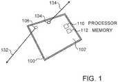
- Fig. 1is a schematic illustration of a mobile device 100 which may be configured to operate in accordance with an embodiment of the invention.
- Device 100optionally comprises a touch screen 102, a front camera 104, having an imaging axis 134, on the same side as the touch screen 102 and a rear camera 106, having an imaging axis 132, directed in an opposite direction from front camera 104.
- a processor 110 and a memory 112are embedded within mobile device 100.
- Processor 110is configured with software to carry out distance estimation based on images acquired by front camera 104 and rear camera 106 as described herein below.
- Device 100optionally comprises a smart-phone or tablet, although other devices having the elements discussed herein may also be used.
- processor 110is configured to perform various tasks other than distance estimation, such as encoding and decoding speech signals, and/or any other tasks known to be performed by mobile devices.
- the softwaremay be downloaded to processor 110 in electronic form, over a network, for example, and stored in memory 112.
- the softwaremay be held on tangible, non-transitory storage media, such as optical, magnetic, or electronic memory media.
- at least some of the functions of processor 110may be performed by dedicated or programmable hardware logic circuits.
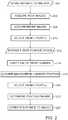
- Fig. 2is a flowchart of acts performed in estimating a distance to an object, in accordance with an embodiment of the invention.
- rear camera 106is aimed at the object and mobile device 100 optionally begins to execute a software process that manages a distance estimation procedure.
- mobile device 100acquires (206) one or more images through rear camera 106, which is aimed at the object, and in addition acquires (208) one or more images through front camera 104.
- a single image pairreferred to herein as (Rear1, Front1), is selected (210) to represent the rear camera and front camera images.
- Mobile device 100then optionally instructs (212) the user to change the position or pose of mobile device 100 to a new position and aim front camera 104 in the same direction as before the change in position.
- Mobile device 100optionally verifies (214) that front camera 104 is properly aimed and then acquires (216) one or more images by both the front and rear cameras.
- Mobile device 100optionally selects (218) a single image acquired from the new position for each of the front and rear cameras. The selected pair of images from after the position change is referred to herein as (Rear2, Front2).
- Mobile device 100analyzes the selected images acquired before (Rear1, Front1) and after (Rear2, Front2) the position change, to determine (222) the change in position of the rear camera 106 due to the change in the position of mobile device 100. Based on the determined change in the position in the rear camera and the selected images of the object (Rear1 and Rear2) from before and after the change, the distance to the object is estimated (224), as detailed hereinbelow.
- the instructions (212) to the user to change the position or pose of device 100include a display of a current video stream acquired by front camera 104, allowing the user to adjust the position of front camera 104 according to the images it is currently acquiring.
- the instructions (212) to the userfurther include the selected (210) image acquired by front camera 104 before the position change (Front1), so the user can easily match the current position of front camera 104 to the selected (210) previously acquired image Front1.
- the current video streamis overlaid on the displayed image Front1 to allow simple alignment by the user.
- the current video streammay be displayed side by side with image Front1, possibly with a suitable grid correlating between the images.
- a shadow or grid extracted from the Front1 imageis displayed, and the user is requested to match the current video stream to the displayed shadow or grid.
- processor 110compares the images of an image stream currently collected by front camera 104 and the selected Front1 image, for example using feature matching, and accordingly provides aiming instructions, for example in the form of displayed arrows and/or other graphical guidance or spoken directions.
- the feature matchingoptionally includes selecting a feature appearing in both Front1 and the images of the currently collected image stream and determining the relative positions of the features in Front1 and the image stream.
- processor 110calculates a numerical matching extent score and displays the calculated matching extent score to the user.
- processor 110provides a stop instruction when the matching extent is above a predetermined threshold.
- the thresholdmay be a preconfigured threshold used universally, or may be a dynamically adjustable threshold according to a required accuracy level of the distance determination.
- a relatively low thresholdis required and processor 110 digitally compensates for the mismatch by performing image rectification, as described hereinbelow.
- the instructions (212)also request the user to remain still until the images are acquired, in order to minimize the position changes between acquiring (Rear1, Front1) and (Rear2, Front2).
- the estimated distanceis optionally provided to the user by display on screen 102, sounding to the user or any other suitable method.
- the distancemay be used by processor 110 or provided to a different processor, for further calculations.
- processor 110may optionally determine other sizes and/or distances in the scene, such as the size of the object and/or the distances and sizes of other objects in the images.
- device 100may operate as a measurement tool.
- the distance estimationis used to apply scale-in augmented reality applications, for example in overlaying virtual objects on an image, stream of images or live scene.
- the object sizeis used by processor 110 to improve object tracking between image frames in a video stream acquired by mobile device 100, for example in surveillance applications.
- the instruction (204) to estimate a distance to an objectis provided, in some embodiments, by a human user, who is aware of the estimation and participates knowingly in the process. In other embodiments, the instruction (204) to estimate a distance is provided automatically by another software running on device 100. In these embodiments, the user may participate knowingly in the process or may not be aware of the process.
- the instruction (212) to move the device to a new positionmay be provided among other instructions provided by the other software initiating the distance estimation, such that the user does not necessarily know that the instructions are performed for distance estimation.
- the instruction (212) to change the position of device 100is provided in an implied manner, without the user necessarily understanding that there was an instruction. For example, an image on screen 102 may be rotated in order to cause the user to instinctively rotate device 100.
- At least three, at least five or even at least ten imagesare acquired by each of the cameras in each of the acquiring sessions (e.g., before and after the position change).
- the quality of the imagesare assessed as they are acquired and the image acquiring is repeated until an image, a predetermined number of images or pairs of front and rear images considered to have a sufficient quality, are acquired. Accordingly, in these embodiments, the number of acquired images varies according to the quality of the acquired images. Optionally, the same number of images is acquired by the front and rear cameras.
- front camera 104may be instructed to acquire more images than rear camera 106.
- the front and rear camera images of each pairare acquired simultaneously or within a very short time difference, such as within less than 5 seconds, less than 1 second, less than a half a second, possibly even less than 30 milliseconds.
- the same criterionis used in determining the number of images acquired before and after the position change of device 100.
- imagesare acquired until a predetermined number of images of sufficient quality were acquired.
- the same number of imagesis acquired before and after the position change.
- more imagesare acquired before the position change or after the position change.
- the quality assessment after the position changeincludes in addition to an objective quality, or instead of an objective quality, a matching measure indicative of the extent to which the image matches the images acquired before the position change.
- the image selection (210) of (Rear1, Front1)is performed based on quality assessment methods, such as verifying that the image has strong gradients and/or that the camera did not move while acquiring the picture (e.g., based on accelerometer measurements and/or image analysis).
- the selectionincludes selecting Rear1 as the best quality image acquired before the position change by rear camera 106, and selecting the corresponding front camera image acquired at the same time to be Front1.
- the selection of Rear1 and Front1is based on a weighted score giving different weight to the quality of the rear image and to the quality of the front image.
- the time difference between acquiring each pair of imagesis also factored into the score.
- the selectionprovides a combination of two or more images, for example generated as a weighted sum of the images or of those images considered having a quality above a given threshold.
- low quality imagese.g., blurred images
- the weighted selected imagesare calculated only based on the images considered of sufficient quality.
- the image selection (218) of (Rear2, Front2)may be performed in a manner similar to the selection (210) of (Rear1, Front1).
- Front2is selected as the first image considered sufficiently aligned to Front1, which has a sufficient quality.
- processor 110determines the location of the user relative to the background in the Front1 selected image, and analyzes the images acquired after the position change based on the extent to which the location of the user relative to the background in these images, matches the relative location in Front1.
- the image acquired after the position change, which best matches Front1is selected.
- analyzed images having a difference in location beyond a predetermined valueare weeded out from consideration.
- the extent to which the relative location of the user in the analyzed images matches that in Front1is weighted into a quality score used in selecting Front2.
- the useris requested to repeat the acquiring (216) of images after the position change or is requested to repeat the entire procedure of Fig. 2 .
- processor 110also verifies that the axis of the camera as determined from the rear camera images and/or front camera images did not change substantially between the acquiring of images before and after the position change. Alternatively or additionally, rectification is performed to compensate for movement of the camera axis, as detailed hereinbelow.
- the estimation (224)optionally includes image rectification to correct for rotation bias of the images acquired before and after the position change of rear camera 106 (Rear1, Rear2).
- Rear1 and Rear2are adjusted such that they are both in the same plane.
- the rectificationis performed using any suitable method known in the art, such as any of the methods described in US patent publication 2013/0271578, to Richards , US patent publication 2005/0180632 to Aradhye et al. and Lim, Ser-Nam; Mittal, Anurag; Davis, Larry; Paragios, Nikos., "Uncalibrated stereo rectification for automatic 3d surveillance", International Conference on Image Processing 2: 1357-1360, 2004 .
- Processor 110then optionally performs a triangulation method on the rectified versions of Rear1 and Rear2 to determine the distance to one or more points of interest in the images.
- the triangulationis performed using any suitable method known in the art, for example, using any of the methods described in Richard Hartley and Andrew Zisserman (2003), Multiple View Geometry in computer vision. Cambridge University Press.
- the triangulationis optionally based on the distance between the positions of the rear camera 106, before and after the position change, i.e., the positions of rear camera 106 at the time of acquiring Rear1 and Rear2, respectively, and the f-number, also referred to as focal ratio, of rear camera 106.
- estimation (224)includes creating a stereo or disparity image based on the Rear1, Rear2 images.
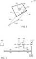
- Fig. 3is a schematic illustration of mobile device 100 in a rotated orientation relative to the orientation of Fig. 1 , in accordance with an embodiment of the invention.
- the change in position of mobile device 100is a rotation of the mobile device.
- the instruction (212) to move mobile device 100 to the new positionincludes in these embodiments, an instruction to rotate the mobile device.
- the useris instructed to position mobile device 100 such that the images acquired by front camera 104 in the new position, after the rotation, are the same as the images acquired before the rotation, adjusted for the extent of rotation of the mobile device 100.
- the useris instructed to rotate mobile device 100 by 180 degrees, to achieve a maximal change in the position of rear camera 106 relative to front camera 104.
- the useris instructed to rotate mobile device 100 by 90 degrees, or any other desired extent.
- the usermay be requested to rotate device 100 to an extent close to 180 degrees, for example between 160-200 degrees, thus allowing the user to perform the rotation quickly without accurately adjusting the rotation to 180 degrees.
- Fig. 3which shows device 100 rotated by 180 degrees relative to its position in Fig. 1
- the distance 332 between the imaging axis of rear camera 106 before 334 and after 336 the rotationis twice the distance 140 between the locations of front camera 104 and rear camera 106, as front camera 104 remains in the same relative location before and after the rotation.
- the determination (222) of the change in position of rear camera 106is based on the known positions of cameras 104 and 106 on device 100.
- the determinationincludes estimation of the extent of rotation of mobile device 100, for example based on a comparison of the images taken by front camera 104 before and after the rotation.
- the estimationis based on a comparison of the images taken by rear camera 106 before and after the rotation.
- the extent of the rotationis known from an angle measurement unit within device 100.
- front camera 104is directed to the user before and after the rotation
- front camera 104is directed at the object whose distance is to be determined before the rotation and is directed at the user after the rotation. This rotation is referred to herein as flipping.
- an image 352 taken by rear camera 106 before the position changeis optionally displayed to the user, and the user is requested to match images 354 currently acquired by front camera 104 with the displayed image.
- the distanceis optionally calculated based on an analysis of an image acquired by front camera 104 before the position change and an image acquired by rear camera 106 acquired after the position change.
- device 100has screens on both sides, in which the instructions to the user are provided as appropriate on the screen facing the user.
- the instruction (212) to move mobile device 100 to the new positionincludes an instruction to change the distance between the mobile device and the user (e.g., the user's face), by moving the device closer to the user or farther from the user.
- Fig. 4is a schematic illustration of distance measurement to an object 402, in accordance with one of these other examples.
- front camera 104acquires an image including a specific body portion (e.g., 410).
- the instruction (212) to the useroptionally states that the image acquired by front camera 104 should include the body portion 410, and possibly includes an instruction to keep the body portion 410 in a central portion of the image.
- the useris instructed to aim the camera such that the body portion is located in the same relative location within the image acquired after the position change, as before the position change.
- the body portionoptionally includes the human cornea, although other body organs having a nearly fixed size for different people may be used.
- a plurality of different body portionsmay be considered and the distance is determined based on a weighted sum of the distance calculated for each body portion.
- processor 110is configured with the size of the body portion in an initialization stage and thereafter the configured size is used in a plurality of subsequent distance measurements performed by the user.
- the configured sizemay be entered manually by the user, based on a measurement performed without use of device 100, or may be performed using device 100, for example in a configuration procedure including acquiring images of the body portion from one or more predetermined distances and/or acquiring a plurality of images from different distances with known relative locations.
- front camera 104is aimed at an object having a known size, such as a ruler, coin or money note.
- a known sizesuch as a ruler, coin or money note.
- the known-size objectis included in the images acquired before and after the position change.
- the known-size objectis placed by the user next to the body portion, so that the size of the body portion can be determined from the known- size object.
- the known-size objectmay appear in only some of the images acquired.
- the change in positionis optionally determined (222) in these embodiments, based on a comparison of the size of the imaged body portion 410 in the front images before and after the position change (Front1, Front2).
- processor 110counts the number of pixels over which the cornea (or other specific body organ) spans in image Front1 and according to the known width of the cornea and the field of view (iFov) of front camera 104, calculates the distance (Fl) between device 100 and the user at the time the image Front1 was acquired.
- the width of the corneais evaluated as the white to white corneal diameter.
- Processor 110optionally additionally determines the size ratio of the cornea and/or other body portions between Front1 and Front2, referred to herein as FrontZoom and the size ratio of one or more features between Rear1 and Rear2, referred to herein as RearZoom.
- the one or more features used in calculating RearZoomare optionally selected using known methods of feature detection, matching and/or tracking, such as optical flow, speeded up robust features (SURF) and/or scale invariant feature transform (SIFT).
- SURFspeeded up robust features
- SIFTscale invariant feature transform
- R 1F 1 ⁇ FrontZoom ⁇ 1 / 1 ⁇ RearZoom
- the calculationincludes determining the new distance (F2) between user 408 and device 100, after the position change, in a manner similar to the calculation of F1.
- F2may then be used to calculate FrontZoom and/or R2.
- Device 100 in some of the above embodimentsis assumed to be rigid, at least in portions on which cameras 104 and 106 are mounted, such that the relative positions of the cameras does not change.
- device 100may be flexible and/or cameras 104 and/or 106 are movably mounted on device 100, such that the relative positions of the cameras on device 100 may change.
- processor 110is optionally configured to receive information on the pose of device 100, which pose information includes not only the location and orientation of device 100, but also the relative locations of cameras 104 and 106 on device 100.
- device 100is assumed to be held by a user and the instructions as to changing the position of the device are provided to the user.
- device 100is mounted on a tripod, arm or other mount which includes a motor or other device which controls its movement.
- the mountis configured to receive movement instructions directly from device 100, such that the entire method of Fig. 2 is carried out automatically without human aid.
- Such a setupmay be used, for example, for surveillance purposes.
Landscapes
- Engineering & Computer Science (AREA)
- Physics & Mathematics (AREA)
- General Physics & Mathematics (AREA)
- Theoretical Computer Science (AREA)
- Multimedia (AREA)
- Remote Sensing (AREA)
- Radar, Positioning & Navigation (AREA)
- Electromagnetism (AREA)
- Computer Vision & Pattern Recognition (AREA)
- Signal Processing (AREA)
- Human Computer Interaction (AREA)
- Optics & Photonics (AREA)
- Health & Medical Sciences (AREA)
- General Health & Medical Sciences (AREA)
- Vascular Medicine (AREA)
- Image Analysis (AREA)
- Geometry (AREA)
- Studio Devices (AREA)
- Length Measuring Devices By Optical Means (AREA)
- Image Processing (AREA)
Description
- The present invention relates to distance measurement and in particular to distance measurement by portable devices.
- Mobile devices, once used solely for telephone communications, are used for a wide range of tasks and include various apparatus.
- Korean patent publication
2013/0022831 to Ryoo 202940864 to Wu Hao describes incorporating a distance sensor into a mobile phone. Chinese patent publication10334213 to Liu Guohua describes measuring distance using two cameras with a known distance between them. - These devices either lack sufficient accuracy or require additional hardware not included in many existing mobile devices.
CN103017730 and its equivalentEP2927634A2 discloses a single camera ranging method of determine a distance from a mobile terminal to a target object in an image by laterally shifting the mobile terminal to take two images and the lateral shift is detected by a three-axis gyro.US2005/0270368 discloses a motion sensor using two cameras in which two different direction images are used to determine motion of a portable device carrying the two cameras. Other disclosures relating to the use of mobile device cameras to measure distances to objects may be found inUS2005/270368 ,US8259161 B1 andHOLZMANN, C. ET AL.: "Measuring distance with mobile phones using single-camera stereo vision", DISTRIBUTED COMPUTING SYSTEMS WORKSHOPS (ICDCSW), 2012 32ND INTERNATIONAL CONFERENCE ON, June 2012 (2012-06), pages 88-93.US2007/0019000 discloses a display control device for controlling a displayed image by detecting a position and orientation of an apparatus having a user side camera and an opposite side camera. Images from both cameras are processed to determine the distance between a user's face and the apparatus and the relative orientation of the apparatus to the user's face. The document notes that positions of the two cameras may be different, and explains that where such cameras are small in size, the difference can be ignored. For cases when it can not be ignored, the position may be corrected based on the geometric positions of the two cameras, or and there may be a case when the mean value of the two camera positions can be applied.- The present invention provides a method and a device for measuring a distance to an object as defined in the appended claims 1 and 8 respectively.
- There is further provided in accordance with the invention, a computer program product as defined in the appended claim 13.
- Exemplary non-limiting embodiments of the invention will be described with reference to the following description in conjunction with the figures. Identical structures, elements or parts which appear in more than one figure are preferably labeled with a same or similar number in all the figures in which they appear, in which:
Fig. 1 is a schematic illustration of amobile device 100 which may be configured to operate in accordance with an embodiment of the invention;Fig. 2 is a flowchart of acts performed in estimating a distance to an object, in accordance with an embodiment of the invention;Fig. 3 is a schematic illustration of the mobile device in a rotated orientation relative to the orientation ofFig. 1 , in accordance with an embodiment of the invention; andFig. 4 is a schematic diagram of a calculation of the distance to an object based on images acquired from two different positions.- An aspect of some embodiments of the invention relates to a method of measuring a distance to an object by a mobile device including at least two cameras. At least two images including the object are acquired from respective different positions of the device. Substantially concurrently with acquiring the images including the object (referred to herein as "object images"), respective reference images are acquired by a different camera than the camera acquiring the respective object image. The reference images are used to determine the relative positions of the camera(s) when the at least two images of the object were acquired and using the at least two images and the relative positions of the cameras, the distance to the object is determined.
- In some embodiments, the different positions of the cameras acquiring the images are achieved by rotating the device and positioning the camera acquiring the reference images such that the reference images are substantially identical. The relative position of the camera acquiring the object images can then be determined from the extent of rotation and the positions of the cameras on the device.
- The term device position is used herein to relate to both the location and orientation of the device, such that two different orientations of the device, even if the device is in the same location, are referred to herein as two different positions.
- In some embodiments of the invention, the object images are all acquired by a first camera and the reference images are all acquired by a second camera. In other embodiments, however, a same camera of the device is used for one or more of the object images and one or more of the reference images.
Fig. 1 is a schematic illustration of amobile device 100 which may be configured to operate in accordance with an embodiment of the invention.Device 100 optionally comprises atouch screen 102, afront camera 104, having animaging axis 134, on the same side as thetouch screen 102 and arear camera 106, having animaging axis 132, directed in an opposite direction fromfront camera 104. Aprocessor 110 and amemory 112 are embedded withinmobile device 100.Processor 110 is configured with software to carry out distance estimation based on images acquired byfront camera 104 andrear camera 106 as described herein below.Device 100 optionally comprises a smart-phone or tablet, although other devices having the elements discussed herein may also be used. Generally,processor 110 is configured to perform various tasks other than distance estimation, such as encoding and decoding speech signals, and/or any other tasks known to be performed by mobile devices.- The software may be downloaded to
processor 110 in electronic form, over a network, for example, and stored inmemory 112. Alternatively or additionally, the software may be held on tangible, non-transitory storage media, such as optical, magnetic, or electronic memory media. Further alternatively or additionally, at least some of the functions ofprocessor 110 may be performed by dedicated or programmable hardware logic circuits. Fig. 2 is a flowchart of acts performed in estimating a distance to an object, in accordance with an embodiment of the invention.- When
mobile device 100 is instructed (204) to estimate a distance to an object,rear camera 106 is aimed at the object andmobile device 100 optionally begins to execute a software process that manages a distance estimation procedure. At the beginning of the estimation procedure,mobile device 100 acquires (206) one or more images throughrear camera 106, which is aimed at the object, and in addition acquires (208) one or more images throughfront camera 104. Optionally, a single image pair, referred to herein as (Rear1, Front1), is selected (210) to represent the rear camera and front camera images. Mobile device 100 then optionally instructs (212) the user to change the position or pose ofmobile device 100 to a new position and aimfront camera 104 in the same direction as before the change in position.Mobile device 100 optionally verifies (214) thatfront camera 104 is properly aimed and then acquires (216) one or more images by both the front and rear cameras.Mobile device 100 optionally selects (218) a single image acquired from the new position for each of the front and rear cameras. The selected pair of images from after the position change is referred to herein as (Rear2, Front2).Mobile device 100 analyzes the selected images acquired before (Rear1, Front1) and after (Rear2, Front2) the position change, to determine (222) the change in position of therear camera 106 due to the change in the position ofmobile device 100. Based on the determined change in the position in the rear camera and the selected images of the object (Rear1 and Rear2) from before and after the change, the distance to the object is estimated (224), as detailed hereinbelow.- In embodiments of the invention, the instructions (212) to the user to change the position or pose of
device 100 include a display of a current video stream acquired byfront camera 104, allowing the user to adjust the position offront camera 104 according to the images it is currently acquiring. - Optionally, the instructions (212) to the user further include the selected (210) image acquired by
front camera 104 before the position change (Front1), so the user can easily match the current position offront camera 104 to the selected (210) previously acquired image Front1. Optionally, the current video stream is overlaid on the displayed image Front1 to allow simple alignment by the user. Alternatively, the current video stream may be displayed side by side with image Front1, possibly with a suitable grid correlating between the images. Further alternatively or additionally, rather than displaying the Front1 image, a shadow or grid extracted from the Front1 image is displayed, and the user is requested to match the current video stream to the displayed shadow or grid. - Alternatively or additionally,
processor 110 compares the images of an image stream currently collected byfront camera 104 and the selected Front1 image, for example using feature matching, and accordingly provides aiming instructions, for example in the form of displayed arrows and/or other graphical guidance or spoken directions. The feature matching optionally includes selecting a feature appearing in both Front1 and the images of the currently collected image stream and determining the relative positions of the features in Front1 and the image stream. - In some embodiments of the invention,
processor 110 calculates a numerical matching extent score and displays the calculated matching extent score to the user. Alternatively or additionally,processor 110 provides a stop instruction when the matching extent is above a predetermined threshold. The threshold may be a preconfigured threshold used universally, or may be a dynamically adjustable threshold according to a required accuracy level of the distance determination. In some embodiments of the invention, a relatively low threshold is required andprocessor 110 digitally compensates for the mismatch by performing image rectification, as described hereinbelow. - Optionally, the instructions (212) also request the user to remain still until the images are acquired, in order to minimize the position changes between acquiring (Rear1, Front1) and (Rear2, Front2).
- The estimated distance is optionally provided to the user by display on
screen 102, sounding to the user or any other suitable method. Alternatively or additionally, the distance may be used byprocessor 110 or provided to a different processor, for further calculations. Based on the distance to the object,processor 110 may optionally determine other sizes and/or distances in the scene, such as the size of the object and/or the distances and sizes of other objects in the images. Thus,device 100 may operate as a measurement tool. Alternatively or additionally, the distance estimation is used to apply scale-in augmented reality applications, for example in overlaying virtual objects on an image, stream of images or live scene. In some embodiments of the invention, the object size is used byprocessor 110 to improve object tracking between image frames in a video stream acquired bymobile device 100, for example in surveillance applications. - The instruction (204) to estimate a distance to an object is provided, in some embodiments, by a human user, who is aware of the estimation and participates knowingly in the process. In other embodiments, the instruction (204) to estimate a distance is provided automatically by another software running on
device 100. In these embodiments, the user may participate knowingly in the process or may not be aware of the process. For example, the instruction (212) to move the device to a new position may be provided among other instructions provided by the other software initiating the distance estimation, such that the user does not necessarily know that the instructions are performed for distance estimation. Alternatively or additionally, the instruction (212) to change the position ofdevice 100 is provided in an implied manner, without the user necessarily understanding that there was an instruction. For example, an image onscreen 102 may be rotated in order to cause the user to instinctively rotatedevice 100. - Referring in more detail to acquiring (206, 208, 216) images through
front camera 104 andrear camera 106, in some embodiments of the invention, at least three, at least five or even at least ten images are acquired by each of the cameras in each of the acquiring sessions (e.g., before and after the position change). In some embodiments of the invention, the quality of the images are assessed as they are acquired and the image acquiring is repeated until an image, a predetermined number of images or pairs of front and rear images considered to have a sufficient quality, are acquired. Accordingly, in these embodiments, the number of acquired images varies according to the quality of the acquired images. Optionally, the same number of images is acquired by the front and rear cameras. Alternatively, more images are acquired by therear camera 106, as the chances that the images of the rear camera are blurred or otherwise unsuitable are generally relatively higher than the chances that the front camera images are blurred. It is noted, however, that in cases in whichfront camera 104 is expected to have higher chances of providing unsuitable images,front camera 104 may be instructed to acquire more images thanrear camera 106. - Optionally, in cases in which the front and rear images are acquired in pairs, the front and rear camera images of each pair are acquired simultaneously or within a very short time difference, such as within less than 5 seconds, less than 1 second, less than a half a second, possibly even less than 30 milliseconds.
- Optionally, the same criterion is used in determining the number of images acquired before and after the position change of
device 100. In some embodiments, in both image acquiring sessions, images are acquired until a predetermined number of images of sufficient quality were acquired. Alternatively, the same number of images is acquired before and after the position change. In other embodiments, more images are acquired before the position change or after the position change. In some embodiments of the invention, the quality assessment after the position change includes in addition to an objective quality, or instead of an objective quality, a matching measure indicative of the extent to which the image matches the images acquired before the position change. - Optionally, the image selection (210) of (Rear1, Front1) is performed based on quality assessment methods, such as verifying that the image has strong gradients and/or that the camera did not move while acquiring the picture (e.g., based on accelerometer measurements and/or image analysis). Optionally, the selection includes selecting Rear1 as the best quality image acquired before the position change by
rear camera 106, and selecting the corresponding front camera image acquired at the same time to be Front1. Alternatively, after selecting Rear1, Front1 is selected among a limited number of images acquired within a short period of time before, in parallel to and/or after acquiring Rear1. Alternatively, the selection of Rear1 and Front1 is based on a weighted score giving different weight to the quality of the rear image and to the quality of the front image. In some embodiments, the time difference between acquiring each pair of images is also factored into the score. - Alternatively or additionally, the selection provides a combination of two or more images, for example generated as a weighted sum of the images or of those images considered having a quality above a given threshold. Optionally, low quality images (e.g., blurred images) are filtered out, and the weighted selected images are calculated only based on the images considered of sufficient quality.
- The image selection (218) of (Rear2, Front2) may be performed in a manner similar to the selection (210) of (Rear1, Front1). Alternatively, Front2 is selected as the first image considered sufficiently aligned to Front1, which has a sufficient quality.
- In some embodiments,
processor 110 determines the location of the user relative to the background in the Front1 selected image, and analyzes the images acquired after the position change based on the extent to which the location of the user relative to the background in these images, matches the relative location in Front1. Optionally, the image acquired after the position change, which best matches Front1 is selected. Alternatively, analyzed images having a difference in location beyond a predetermined value are weeded out from consideration. Further alternatively, the extent to which the relative location of the user in the analyzed images matches that in Front1 is weighted into a quality score used in selecting Front2. - Optionally, if an image of sufficient quality and/or matching is not found among the images acquired after the position change, the user is requested to repeat the acquiring (216) of images after the position change or is requested to repeat the entire procedure of
Fig. 2 . - In some embodiments of the invention,
processor 110 also verifies that the axis of the camera as determined from the rear camera images and/or front camera images did not change substantially between the acquiring of images before and after the position change. Alternatively or additionally, rectification is performed to compensate for movement of the camera axis, as detailed hereinbelow. - The estimation (224) optionally includes image rectification to correct for rotation bias of the images acquired before and after the position change of rear camera 106 (Rear1, Rear2). In the image rectification, Rear1 and Rear2 are adjusted such that they are both in the same plane. The rectification is performed using any suitable method known in the art, such as any of the methods described in
US patent publication 2013/0271578, to Richards ,US patent publication 2005/0180632 to Aradhye et al. andLim, Ser-Nam; Mittal, Anurag; Davis, Larry; Paragios, Nikos., "Uncalibrated stereo rectification for automatic 3d surveillance", International Conference on Image Processing 2: 1357-1360, 2004. Processor 110 then optionally performs a triangulation method on the rectified versions of Rear1 and Rear2 to determine the distance to one or more points of interest in the images. The triangulation is performed using any suitable method known in the art, for example, using any of the methods described in Richard Hartley and Andrew Zisserman (2003), Multiple View Geometry in computer vision. Cambridge University Press. The triangulation is optionally based on the distance between the positions of therear camera 106, before and after the position change, i.e., the positions ofrear camera 106 at the time of acquiring Rear1 and Rear2, respectively, and the f-number, also referred to as focal ratio, ofrear camera 106.- In some embodiments of the invention, estimation (224) includes creating a stereo or disparity image based on the Rear1, Rear2 images.
Fig. 3 is a schematic illustration ofmobile device 100 in a rotated orientation relative to the orientation ofFig. 1 , in accordance with an embodiment of the invention. In the embodiments described with reference toFig. 3 , the change in position ofmobile device 100 is a rotation of the mobile device.- The instruction (212) to move
mobile device 100 to the new position includes in these embodiments, an instruction to rotate the mobile device. Optionally, the user is instructed to positionmobile device 100 such that the images acquired byfront camera 104 in the new position, after the rotation, are the same as the images acquired before the rotation, adjusted for the extent of rotation of themobile device 100. In some embodiments, the user is instructed to rotatemobile device 100 by 180 degrees, to achieve a maximal change in the position ofrear camera 106 relative tofront camera 104. In other embodiments, the user is instructed to rotatemobile device 100 by 90 degrees, or any other desired extent. For example, the user may be requested to rotatedevice 100 to an extent close to 180 degrees, for example between 160-200 degrees, thus allowing the user to perform the rotation quickly without accurately adjusting the rotation to 180 degrees. - When rotating by 180 degrees, as illustrated by
Fig. 3 which showsdevice 100 rotated by 180 degrees relative to its position inFig. 1 , thedistance 332 between the imaging axis ofrear camera 106 before 334 and after 336 the rotation is twice thedistance 140 between the locations offront camera 104 andrear camera 106, asfront camera 104 remains in the same relative location before and after the rotation. - The determination (222) of the change in position of
rear camera 106, is based on the known positions ofcameras device 100. In some embodiments of the invention, the determination includes estimation of the extent of rotation ofmobile device 100, for example based on a comparison of the images taken byfront camera 104 before and after the rotation. Alternatively or additionally, the estimation is based on a comparison of the images taken byrear camera 106 before and after the rotation. Further alternatively, the extent of the rotation is known from an angle measurement unit withindevice 100. - While in the above
description front camera 104 is directed to the user before and after the rotation, in other embodiments,front camera 104 is directed at the object whose distance is to be determined before the rotation and is directed at the user after the rotation. This rotation is referred to herein as flipping. In these embodiments, after the position change, animage 352 taken byrear camera 106 before the position change is optionally displayed to the user, and the user is requested to matchimages 354 currently acquired byfront camera 104 with the displayed image. The distance is optionally calculated based on an analysis of an image acquired byfront camera 104 before the position change and an image acquired byrear camera 106 acquired after the position change. In some embodiments,device 100 has screens on both sides, in which the instructions to the user are provided as appropriate on the screen facing the user. - In other examples disclosed herein, the instruction (212) to move
mobile device 100 to the new position, includes an instruction to change the distance between the mobile device and the user (e.g., the user's face), by moving the device closer to the user or farther from the user. Fig. 4 is a schematic illustration of distance measurement to anobject 402, in accordance with one of these other examples.- Optionally, in both the original position (e.g., 404) and the position after the change (e.g., 406),
front camera 104 acquires an image including a specific body portion (e.g., 410). The instruction (212) to the user optionally states that the image acquired byfront camera 104 should include thebody portion 410, and possibly includes an instruction to keep thebody portion 410 in a central portion of the image. Alternatively or additionally, the user is instructed to aim the camera such that the body portion is located in the same relative location within the image acquired after the position change, as before the position change. The body portion optionally includes the human cornea, although other body organs having a nearly fixed size for different people may be used. In some embodiments, a plurality of different body portions may be considered and the distance is determined based on a weighted sum of the distance calculated for each body portion. - Alternatively or additionally,
processor 110 is configured with the size of the body portion in an initialization stage and thereafter the configured size is used in a plurality of subsequent distance measurements performed by the user. The configured size may be entered manually by the user, based on a measurement performed without use ofdevice 100, or may be performed usingdevice 100, for example in a configuration procedure including acquiring images of the body portion from one or more predetermined distances and/or acquiring a plurality of images from different distances with known relative locations. - Alternatively or additionally to using a body portion,
front camera 104 is aimed at an object having a known size, such as a ruler, coin or money note. In some examples, the known-size object is included in the images acquired before and after the position change. In other examples, the known-size object is placed by the user next to the body portion, so that the size of the body portion can be determined from the known- size object. In these embodiments, the known-size object may appear in only some of the images acquired. - The change in position is optionally determined (222) in these embodiments, based on a comparison of the size of the imaged
body portion 410 in the front images before and after the position change (Front1, Front2). Optionally,processor 110 counts the number of pixels over which the cornea (or other specific body organ) spans in image Front1 and according to the known width of the cornea and the field of view (iFov) offront camera 104, calculates the distance (Fl) betweendevice 100 and the user at the time the image Front1 was acquired. Optionally, the width of the cornea is evaluated as the white to white corneal diameter. - Optionally, the distance between
front camera 104 and the user (Fl) is calculated as: F1 = SizeOfCornealnMeters / (iFovInRadiansToPixel∗ SizeOfCornealnPixels)Processor 110 optionally additionally determines the size ratio of the cornea and/or other body portions between Front1 and Front2, referred to herein as FrontZoom and the size ratio of one or more features between Rear1 and Rear2, referred to herein as RearZoom. The one or more features used in calculating RearZoom are optionally selected using known methods of feature detection, matching and/or tracking, such as optical flow, speeded up robust features (SURF) and/or scale invariant feature transform (SIFT). - The distance to the object from
device 100 before the position change is optionally estimated (224) as:
- Alternatively or additionally, the calculation includes determining the new distance (F2) between
user 408 anddevice 100, after the position change, in a manner similar to the calculation of F1. F2 may then be used to calculate FrontZoom and/or R2. Device 100 in some of the above embodiments is assumed to be rigid, at least in portions on whichcameras device 100 may be flexible and/orcameras 104 and/or 106 are movably mounted ondevice 100, such that the relative positions of the cameras ondevice 100 may change. In such embodiments,processor 110 is optionally configured to receive information on the pose ofdevice 100, which pose information includes not only the location and orientation ofdevice 100, but also the relative locations ofcameras device 100.- In the above description,
device 100 is assumed to be held by a user and the instructions as to changing the position of the device are provided to the user. In other embodiments,device 100 is mounted on a tripod, arm or other mount which includes a motor or other device which controls its movement. The mount is configured to receive movement instructions directly fromdevice 100, such that the entire method ofFig. 2 is carried out automatically without human aid. Such a setup may be used, for example, for surveillance purposes. - It will be appreciated that the above described methods may be varied in many ways, including, changing the specific elements used and their layout and changing the order of acts in the methods. It should also be appreciated that the above described description of methods and apparatus are to be interpreted as including apparatus for carrying out the methods and methods of using the apparatus. The present invention has been described using non-limiting detailed descriptions of embodiments thereof that are provided by way of example and are not intended to limit the scope of the invention, which is defined by the appended claims. Many specific implementation details may be used.
- It should be understood that features and/or steps described with respect to one embodiment may be used with other embodiments and that not all embodiments of the invention have all of the features and/or steps shown in a particular figure or described with respect to one of the embodiments. Variations of embodiments described will occur to persons of the art.
- It is noted that some of the above described embodiments may describe the best mode contemplated by the inventors and therefore may include structure, acts or details of structures and acts that may not be essential to the invention and which are described as examples. Therefore, the scope of the invention is defined only by the appended claims.

Claims (14)
- A method of measuring a distance to an object, by a device (100) having at least two cameras (104, 106), the method comprising:acquiring one or more first object images (206) including the object by a first camera (104) of the device (100) and one or more first reference images (208) by a second camera (106) of the device (100), while the device (100) is in a first position (334), said first and second cameras being on opposite sides of the device;after acquiring the one or more first object images, displaying (212) to a user a video stream (354) currently acquired by one of said first and second cameras (104, 106), so that the user can use the video stream in directing the device (100) to a second position (336), wherein a change in position of the device (100) includes a rotation of the device (100) relative to the first position;acquiring (216) one or more second object images including the object by the other of said first and second cameras and acquiring one or more second reference images, by the one of said first and second cameras of the device, while the device (100) is in the second position (336);determining (222), based on the first and second reference images and on knowledge of the extent of rotation and the positions of the first and second cameras on the device, information on a displacement (332) of at least one of said first and second cameras of the device (100) between the first and second positions (334, 336); andcalculating (224) the distance from the device (100) to the object, based on the first and second object images including the object and the determined information on the displacement of the at least one of said first and second cameras (104, 106).
- The method of claim 1, comprising displaying (212) to a user instructions directing to change the position of the device (100) to the second position (406), after acquiring the one or more first object images.
- The method of claim 1, wherein said currently acquired video stream (354) is displayed overlaid on at least one of the one or more first reference images (352), so that the user can use the video stream in directing the device (100) to the second position by matching the overlaid images (352, 354).
- The method of claim 1, wherein the first camera is a rear camera of the device and is used to capture the first and second object images, and the second camera is a front camera of the device and is used to capture the first and second reference images.
- The method of claim 1, wherein the first camera is a front camera of the device and is used to capture the first object image and the second reference images, and the second camera is a rear camera of the device and is used to capture the first reference images and the second object images.
- The method of claim 1, wherein determining information on the displacement of the at least one of said first and second cameras is based at least partly on a known distance between said first and second cameras.
- The method of claim 1, wherein the one or more first object images including the object and the one or more first reference images are acquired in pairs of reference images and object images, the images of each pair being acquired substantially concurrently within less than 1 second.
- A device (100) for measuring a distance to an object, the device (100) comprising:a housing;a first camera (104) included in the housing;a second camera (106) included in the housing, the first and second cameras being on opposite sides of the housing; anda processor (110), included in the housing, configured for:acquiring one or more first object images (206) including the object by a first camera (104) of the device (100) and one or more first reference images (208) by a second camera (106) of the device (100), while the device (100) is in a first position (334);after acquiring the one or more first object images, displaying (212) to a user a video stream (354) currently acquired by one of said first and second cameras (104, 106), so that the user can use the video stream in directing the device (100) to a second position (336), wherein a change in position of the device (100) includes a rotation of the device (100) relative to the first position (334);acquiring (216) one or more second object images including the object by the other of said first and second cameras and acquiring one or more second reference images, by the one of said first and second cameras of the device, while the device (100) is in the second position (336);determining (222), based on the first and second reference images and on knowledge of the extent of rotation and the positions of the first and second cameras on the device, information on a displacement (332) of at least one of said first and second cameras (104, 106) of the device (100) between the first and second positions (334, 336); andcalculating (224) the distance from the device (100) to the object, based on the first and second object images including the object and the determined information on the displacement of the at least one of said first and second cameras (104, 106).
- The device of claim 8, wherein the processor is configured to control the first and second cameras to acquire the images in pairs of concurrently acquired object images and respective reference images.
- The device of claim 8, wherein the processor is configured to provide, after receiving the one or more first object images and first reference images, instructions on changing the position of the device (100), for acquiring the second object images and second reference images.
- The device of claim 8, wherein the processor is configured to analyze an input stream provided by the second camera (106) relative to the one or more first reference images, after receiving the one or more first object images and first reference images, in order to determine when the device (100) is in the second position suitable for acquiring the second reference images and the second object images.
- The device of claim 8, wherein the processor is configured to determine an extent of relative rotation between the first and second reference images and use the determined extent of relative rotation in determining the displacement of the at least one camera of the device between acquiring the first object image and acquiring the second object image.
- A computer program product comprising computer readable program code which, when executed by a processor of a device according to claim 8, performs the steps of the method of any of claims 1 to 7.
- A computer program product according to claim 13, comprising a computer readable non-transitory storage medium (112) carrying the computer readable program code which, when executed by a processor of a device according to claim 8, performs the steps of the method of any of claims 1 to 7.
Priority Applications (1)
| Application Number | Priority Date | Filing Date | Title |
|---|---|---|---|
| EP21152823.7AEP3828496A1 (en) | 2013-04-08 | 2014-04-06 | Distance estimation using multi-camera device |
Applications Claiming Priority (3)
| Application Number | Priority Date | Filing Date | Title |
|---|---|---|---|
| US201361809464P | 2013-04-08 | 2013-04-08 | |
| US201361809447P | 2013-04-08 | 2013-04-08 | |
| PCT/IB2014/060462WO2014167475A1 (en) | 2013-04-08 | 2014-04-06 | Distance estimation using multi-camera device |
Related Child Applications (2)
| Application Number | Title | Priority Date | Filing Date |
|---|---|---|---|
| EP21152823.7ADivisionEP3828496A1 (en) | 2013-04-08 | 2014-04-06 | Distance estimation using multi-camera device |
| EP21152823.7ADivision-IntoEP3828496A1 (en) | 2013-04-08 | 2014-04-06 | Distance estimation using multi-camera device |
Publications (3)
| Publication Number | Publication Date |
|---|---|
| EP2984448A1 EP2984448A1 (en) | 2016-02-17 |
| EP2984448A4 EP2984448A4 (en) | 2016-12-07 |
| EP2984448B1true EP2984448B1 (en) | 2021-02-24 |
Family
ID=51689011
Family Applications (2)
| Application Number | Title | Priority Date | Filing Date |
|---|---|---|---|
| EP14782545.9AActiveEP2984448B1 (en) | 2013-04-08 | 2014-04-06 | Distance estimation using multi-camera device |
| EP21152823.7APendingEP3828496A1 (en) | 2013-04-08 | 2014-04-06 | Distance estimation using multi-camera device |
Family Applications After (1)
| Application Number | Title | Priority Date | Filing Date |
|---|---|---|---|
| EP21152823.7APendingEP3828496A1 (en) | 2013-04-08 | 2014-04-06 | Distance estimation using multi-camera device |
Country Status (5)
| Country | Link |
|---|---|
| US (6) | US10192312B2 (en) |
| EP (2) | EP2984448B1 (en) |
| KR (10) | KR102210054B1 (en) |
| CN (2) | CN105339756B (en) |
| WO (1) | WO2014167475A1 (en) |
Families Citing this family (10)
| Publication number | Priority date | Publication date | Assignee | Title |
|---|---|---|---|---|
| KR102210054B1 (en) | 2013-04-08 | 2021-02-02 | 스냅 아이엔씨 | Distance estimation using multi-camera device |
| WO2016025962A1 (en)* | 2014-08-15 | 2016-02-18 | The University Of Akron | Device and method for three-dimensional video communication |
| WO2016086379A1 (en) | 2014-12-04 | 2016-06-09 | SZ DJI Technology Co., Ltd. | Imaging system and method |
| CN110658918B (en)* | 2019-09-25 | 2023-12-12 | 京东方科技集团股份有限公司 | Positioning method, device and medium for eyeball tracking camera of video glasses |
| CN111207688B (en)* | 2020-01-16 | 2022-06-03 | 睿镞科技(北京)有限责任公司 | Method, device and vehicle for measuring distance to target object in a vehicle |
| CN112378507B (en)* | 2020-11-05 | 2021-10-01 | 浙江大学 | A computer vision-based structural vibration monitoring method based on motion compensation |
| KR20230116565A (en)* | 2022-01-28 | 2023-08-04 | 삼성전자주식회사 | Electronic device and controlling method thereof |
| US12277632B2 (en) | 2022-04-26 | 2025-04-15 | Snap Inc. | Augmented reality experiences with dual cameras |
| US12341738B2 (en) | 2022-06-02 | 2025-06-24 | Snap Inc. | Contextual reply augmentation system |
| US12301941B2 (en) | 2023-05-23 | 2025-05-13 | Snap Inc. | Recommending relevant content augmentations based on context |
Family Cites Families (78)
| Publication number | Priority date | Publication date | Assignee | Title |
|---|---|---|---|---|
| AU704947B2 (en)* | 1993-05-18 | 1999-05-06 | University Of Utah Research Foundation | Apparatus and methods for multianalyte homogeneous fluoroimmunoassays |
| DE69526977T2 (en)* | 1994-10-28 | 2003-01-23 | Lasersight Technologies, Inc. | MULTI-CAMERA DEVICE FOR EXAMINATION OF THE CORNEA |
| US5978773A (en) | 1995-06-20 | 1999-11-02 | Neomedia Technologies, Inc. | System and method for using an ordinary article of commerce to access a remote computer |
| DE59708043D1 (en) | 1996-06-17 | 2002-10-02 | Siemens Ag | Communication system and method for taking and managing digital images |
| US7173651B1 (en) | 1998-06-02 | 2007-02-06 | Knowles Andrew T | Apparatus and system for prompt digital photo delivery and archival |
| JP3255360B2 (en)* | 1999-09-22 | 2002-02-12 | 富士重工業株式会社 | Inspection method of distance data and its inspection device |
| US6505123B1 (en) | 2000-07-24 | 2003-01-07 | Weatherbank, Inc. | Interactive weather advisory system |
| US7738706B2 (en) | 2000-09-22 | 2010-06-15 | Sri International | Method and apparatus for recognition of symbols in images of three-dimensional scenes |
| JP4767403B2 (en)* | 2000-11-06 | 2011-09-07 | 本田技研工業株式会社 | Three-dimensional measuring apparatus and three-dimensional measuring method |
| US20100098702A1 (en) | 2008-09-16 | 2010-04-22 | Longgui Wang | Method of treating androgen independent prostate cancer |
| KR100486596B1 (en) | 2002-12-06 | 2005-05-03 | 엘지전자 주식회사 | Apparatus and control method for driving of reciprocating compressor |
| US7411493B2 (en) | 2003-03-01 | 2008-08-12 | User-Centric Ip, L.P. | User-centric event reporting |
| US7535890B2 (en) | 2003-12-18 | 2009-05-19 | Ayalogic, Inc. | System and method for instant VoIP messaging |
| US20050206874A1 (en)* | 2004-03-19 | 2005-09-22 | Dougherty Robert P | Apparatus and method for determining the range of remote point light sources |
| WO2005119591A1 (en)* | 2004-06-04 | 2005-12-15 | Matsushita Electric Industrial Co., Ltd. | Display control device, display control method, program, and portable apparatus |
| US7671916B2 (en)* | 2004-06-04 | 2010-03-02 | Electronic Arts Inc. | Motion sensor using dual camera inputs |
| JP2006113807A (en)* | 2004-10-14 | 2006-04-27 | Canon Inc | Multi-viewpoint image processing apparatus and image processing program |
| JP4480083B2 (en)* | 2005-02-23 | 2010-06-16 | アイシン精機株式会社 | Object recognition device |
| US8332475B2 (en) | 2005-08-22 | 2012-12-11 | Triplay Communications Ltd. | Messaging system and method |
| JP2007258989A (en)* | 2006-03-22 | 2007-10-04 | Eastman Kodak Co | Digital camera, composition corrector, and composition correcting method |
| CN100588902C (en)* | 2006-12-19 | 2010-02-10 | 北京中星微电子有限公司 | Method and device for detecting vehicle distance |
| JP4986679B2 (en) | 2007-03-29 | 2012-07-25 | 学校法人福岡工業大学 | Non-stationary object three-dimensional image measurement apparatus, three-dimensional image measurement method, and three-dimensional image measurement program |
| EP2147397A4 (en) | 2007-04-23 | 2013-08-21 | Univ Ramot | System, method and a computer readible medium for providing an output image |
| KR101477182B1 (en)* | 2007-06-01 | 2014-12-29 | 삼성전자주식회사 | Terminal and method of shooting an image thereof |
| US7826736B2 (en)* | 2007-07-06 | 2010-11-02 | Flir Systems Ab | Camera and method for use with camera |
| KR100998709B1 (en)* | 2008-04-28 | 2010-12-07 | 한양대학교 산학협력단 | A method of robot localization using spatial semantics of objects |
| US9171221B2 (en)* | 2010-07-18 | 2015-10-27 | Spatial Cam Llc | Camera to track an object |
| US8204299B2 (en)* | 2008-06-12 | 2012-06-19 | Microsoft Corporation | 3D content aggregation built into devices |
| US20100053151A1 (en)* | 2008-09-02 | 2010-03-04 | Samsung Electronics Co., Ltd | In-line mediation for manipulating three-dimensional content on a display device |
| JP5315891B2 (en) | 2008-09-24 | 2013-10-16 | 富士通株式会社 | Distance measuring device, distance measuring method and distance measuring program |
| KR101618759B1 (en)* | 2008-12-24 | 2016-05-09 | 삼성전자주식회사 | Apparatus and method for capturing image |
| FI121440B (en)* | 2009-06-26 | 2010-11-15 | Valtion Teknillinen | Method and apparatus for determining distance |
| US20110025830A1 (en)* | 2009-07-31 | 2011-02-03 | 3Dmedia Corporation | Methods, systems, and computer-readable storage media for generating stereoscopic content via depth map creation |
| US9380292B2 (en)* | 2009-07-31 | 2016-06-28 | 3Dmedia Corporation | Methods, systems, and computer-readable storage media for generating three-dimensional (3D) images of a scene |
| KR101284798B1 (en)* | 2009-12-08 | 2013-07-10 | 한국전자통신연구원 | Apparatus and method for estimating a distance and a position of an object based on an image of a single camera |
| US10080006B2 (en)* | 2009-12-11 | 2018-09-18 | Fotonation Limited | Stereoscopic (3D) panorama creation on handheld device |
| US8687070B2 (en)* | 2009-12-22 | 2014-04-01 | Apple Inc. | Image capture device having tilt and/or perspective correction |
| US9443227B2 (en) | 2010-02-16 | 2016-09-13 | Tigertext, Inc. | Messaging system apparatuses circuits and methods of operation thereof |
| US8890934B2 (en)* | 2010-03-19 | 2014-11-18 | Panasonic Corporation | Stereoscopic image aligning apparatus, stereoscopic image aligning method, and program of the same |
| EP2395765B1 (en)* | 2010-06-14 | 2016-08-24 | Nintendo Co., Ltd. | Storage medium having stored therein stereoscopic image display program, stereoscopic image display device, stereoscopic image display system, and stereoscopic image display method |
| US8933996B2 (en)* | 2010-06-30 | 2015-01-13 | Fujifilm Corporation | Multiple viewpoint imaging control device, multiple viewpoint imaging control method and computer readable medium |
| JP4880096B1 (en)* | 2010-06-30 | 2012-02-22 | 富士フイルム株式会社 | Multi-view shooting control device, multi-view shooting control method, and multi-view shooting control program |
| JP5489897B2 (en)* | 2010-07-22 | 2014-05-14 | パナソニック株式会社 | Stereo distance measuring device and stereo distance measuring method |
| US9946076B2 (en)* | 2010-10-04 | 2018-04-17 | Gerard Dirk Smits | System and method for 3-D projection and enhancements for interactivity |
| US8274552B2 (en)* | 2010-12-27 | 2012-09-25 | 3Dmedia Corporation | Primary and auxiliary image capture devices for image processing and related methods |
| JP5625976B2 (en)* | 2011-02-09 | 2014-11-19 | ソニー株式会社 | IMAGING DEVICE, IMAGING DEVICE CONTROL METHOD, AND PROGRAM |
| US9300947B2 (en)* | 2011-03-24 | 2016-03-29 | Kodak Alaris Inc. | Producing 3D images from captured 2D video |
| US8780180B2 (en)* | 2011-05-13 | 2014-07-15 | Apple Inc. | Stereoscopic camera using anaglyphic display during capture |
| KR20130022831A (en) | 2011-08-26 | 2013-03-07 | 유민규 | Method for measuring distance, height, length using mobile communication terminal |
| US8937646B1 (en)* | 2011-10-05 | 2015-01-20 | Amazon Technologies, Inc. | Stereo imaging using disparate imaging devices |
| WO2013059599A1 (en)* | 2011-10-19 | 2013-04-25 | The Regents Of The University Of California | Image-based measurement tools |
| US9223404B1 (en)* | 2012-01-27 | 2015-12-29 | Amazon Technologies, Inc. | Separating foreground and background objects in captured images |
| US8259161B1 (en)* | 2012-02-06 | 2012-09-04 | Google Inc. | Method and system for automatic 3-D image creation |
| CN102589516B (en)* | 2012-03-01 | 2014-05-28 | 长安大学 | Dynamic distance measuring system based on binocular line scan cameras |
| WO2013136607A1 (en)* | 2012-03-13 | 2013-09-19 | 富士フイルム株式会社 | Imaging device with projector and control method therefor |
| US9019350B2 (en) | 2012-04-12 | 2015-04-28 | Raytheon Company | Stereo rectification method |
| CN104520898A (en)* | 2012-06-08 | 2015-04-15 | 诺基亚公司 | A multi-frame image calibrator |
| US9025859B2 (en)* | 2012-07-30 | 2015-05-05 | Qualcomm Incorporated | Inertial sensor aided instant autofocus |
| CN202940864U (en) | 2012-11-14 | 2013-05-15 | 吴昊 | Mobile phone with replaceable camera |
| CN102997891B (en)* | 2012-11-16 | 2015-04-29 | 上海光亮光电科技有限公司 | Device and method for measuring scene depth |
| CN102980556B (en)* | 2012-11-29 | 2015-08-12 | 小米科技有限责任公司 | A kind of distance-finding method and device |
| CN103017730B (en)* | 2012-11-30 | 2015-04-01 | 中兴通讯股份有限公司 | Single-camera ranging method and single-camera ranging system |
| US9330471B2 (en)* | 2013-02-14 | 2016-05-03 | Qualcomm Incorporated | Camera aided motion direction and speed estimation |
| KR20140108078A (en)* | 2013-02-28 | 2014-09-05 | 삼성전자주식회사 | Method, device, and apparatus for generating stereoscopic images using a non-stereoscopic camera |
| WO2014141654A1 (en)* | 2013-03-13 | 2014-09-18 | パナソニック株式会社 | Distance measurement device, imaging device, and distance measurement method |
| US9967549B2 (en)* | 2013-03-20 | 2018-05-08 | Mediatek Inc. | 3D image capture method with 3D preview of preview images generated by monocular camera and related electronic device thereof |
| KR102210054B1 (en) | 2013-04-08 | 2021-02-02 | 스냅 아이엔씨 | Distance estimation using multi-camera device |
| CN103323461B (en) | 2013-06-14 | 2015-05-27 | 上海大学 | On-line detection method for movement of non-contact type wind driven generator blade |
| CN103344213A (en) | 2013-06-28 | 2013-10-09 | 三星电子(中国)研发中心 | Method and device for measuring distance of double-camera |
| CN103342130B (en) | 2013-07-15 | 2016-02-10 | 齐齐哈尔轨道交通装备有限责任公司 | Hand brake, brake equipment and railway truck |
| CA2863124A1 (en) | 2014-01-03 | 2015-07-03 | Investel Capital Corporation | User content sharing system and method with automated external content integration |
| CN103824318B (en) | 2014-02-13 | 2016-11-23 | 西安交通大学 | A kind of depth perception method of multi-cam array |
| KR102296396B1 (en)* | 2014-07-31 | 2021-09-02 | 삼성전자주식회사 | Apparatus and method for improving accuracy of contactless thermometer module |
| US10704944B2 (en) | 2014-09-14 | 2020-07-07 | Becton, Dickinson And Company | System and method for capturing dose information |
| KR20160133230A (en)* | 2015-05-12 | 2016-11-22 | 엘지전자 주식회사 | Mobile terminal |
| JP2017060008A (en)* | 2015-09-16 | 2017-03-23 | キヤノン株式会社 | Multi-view image encoding apparatus, multi-view image encoding method, and program |
| JP2017086184A (en) | 2015-11-02 | 2017-05-25 | 国立大学法人埼玉大学 | Muscular activity visualization system and muscular activity visualization method |
| KR20170083327A (en)* | 2016-01-08 | 2017-07-18 | 엘지전자 주식회사 | Mobile terminal and method for controlling the same |
- 2014
- 2014-04-06KRKR1020207023225Apatent/KR102210054B1/enactiveActive
- 2014-04-06KRKR1020227045371Apatent/KR102536174B1/enactiveActive
- 2014-04-06KRKR1020227022411Apatent/KR102482186B1/enactiveActive
- 2014-04-06KRKR1020237032236Apatent/KR20230142635A/ennot_activeCeased
- 2014-04-06USUS14/783,119patent/US10192312B2/enactiveActive
- 2014-04-06KRKR1020157031654Apatent/KR102025535B1/enactiveActive
- 2014-04-06EPEP14782545.9Apatent/EP2984448B1/enactiveActive
- 2014-04-06WOPCT/IB2014/060462patent/WO2014167475A1/enactiveApplication Filing
- 2014-04-06KRKR1020217022065Apatent/KR102357800B1/enactiveActive
- 2014-04-06EPEP21152823.7Apatent/EP3828496A1/enactivePending
- 2014-04-06CNCN201480032676.7Apatent/CN105339756B/enactiveActive
- 2014-04-06CNCN201910630729.XApatent/CN110440747B/enactiveActive
- 2014-04-06KRKR1020197027532Apatent/KR102146641B1/enactiveActive
- 2014-04-06KRKR1020217002542Apatent/KR102279380B1/enactiveActive
- 2014-04-06KRKR1020227002988Apatent/KR102416814B1/enactiveActive
- 2014-04-06KRKR1020237017091Apatent/KR102582420B1/enactiveActive
- 2018
- 2018-12-13USUS16/219,519patent/US10467492B2/enactiveActive
- 2019
- 2019-10-02USUS16/591,292patent/US10691967B2/enactiveActive
- 2020
- 2020-05-20USUS16/879,000patent/US11879750B2/enactiveActive
- 2023
- 2023-09-27USUS18/373,685patent/US12209883B2/enactiveActive
- 2024
- 2024-12-12USUS18/979,228patent/US20250130042A1/enactivePending
Non-Patent Citations (1)
| Title |
|---|
| None* |
Also Published As
Similar Documents
| Publication | Publication Date | Title |
|---|---|---|
| US12209883B2 (en) | Distance estimation using multi-camera device | |
| US10297076B2 (en) | Apparatus and method for generating 3D face model using mobile device | |
| CN109960401B (en) | Dynamic projection method, device and system based on face tracking | |
| KR102111935B1 (en) | Display control apparatus, display control method, and program | |
| US10715787B1 (en) | Depth imaging system and method for controlling depth imaging system thereof | |
| KR101459522B1 (en) | Location Correction Method Using Additional Information of Mobile Instrument | |
| WO2019093016A1 (en) | Photographing system, photographing method, and program | |
| JP2012189467A (en) | Positioning device, pace per step data correction method and program | |
| JP2016023962A (en) | Method for measuring subject size, device for measuring subject size, program for measuring subject size, image display method, image display device and image display program |
Legal Events
| Date | Code | Title | Description |
|---|---|---|---|
| PUAI | Public reference made under article 153(3) epc to a published international application that has entered the european phase | Free format text:ORIGINAL CODE: 0009012 | |
| 17P | Request for examination filed | Effective date:20151105 | |
| AK | Designated contracting states | Kind code of ref document:A1 Designated state(s):AL AT BE BG CH CY CZ DE DK EE ES FI FR GB GR HR HU IE IS IT LI LT LU LV MC MK MT NL NO PL PT RO RS SE SI SK SM TR | |
| AX | Request for extension of the european patent | Extension state:BA ME | |
| DAX | Request for extension of the european patent (deleted) | ||
| A4 | Supplementary search report drawn up and despatched | Effective date:20161108 | |
| RIC1 | Information provided on ipc code assigned before grant | Ipc:G06T 7/00 20060101ALI20161102BHEP Ipc:G01C 3/00 20060101AFI20161102BHEP | |
| RAP1 | Party data changed (applicant data changed or rights of an application transferred) | Owner name:C3D AUGMENTED REALITY SOLUTIONS LTD. | |
| STAA | Information on the status of an ep patent application or granted ep patent | Free format text:STATUS: EXAMINATION IS IN PROGRESS | |
| 17Q | First examination report despatched | Effective date:20180215 | |
| GRAP | Despatch of communication of intention to grant a patent | Free format text:ORIGINAL CODE: EPIDOSNIGR1 | |
| STAA | Information on the status of an ep patent application or granted ep patent | Free format text:STATUS: GRANT OF PATENT IS INTENDED | |
| RAP1 | Party data changed (applicant data changed or rights of an application transferred) | Owner name:SNAP INC. | |
| INTG | Intention to grant announced | Effective date:20200319 | |
| GRAJ | Information related to disapproval of communication of intention to grant by the applicant or resumption of examination proceedings by the epo deleted | Free format text:ORIGINAL CODE: EPIDOSDIGR1 | |
| STAA | Information on the status of an ep patent application or granted ep patent | Free format text:STATUS: EXAMINATION IS IN PROGRESS | |
| INTC | Intention to grant announced (deleted) | ||
| GRAP | Despatch of communication of intention to grant a patent | Free format text:ORIGINAL CODE: EPIDOSNIGR1 | |
| STAA | Information on the status of an ep patent application or granted ep patent | Free format text:STATUS: GRANT OF PATENT IS INTENDED | |
| INTG | Intention to grant announced | Effective date:20200907 | |
| GRAS | Grant fee paid | Free format text:ORIGINAL CODE: EPIDOSNIGR3 | |
| GRAA | (expected) grant | Free format text:ORIGINAL CODE: 0009210 | |
| STAA | Information on the status of an ep patent application or granted ep patent | Free format text:STATUS: THE PATENT HAS BEEN GRANTED | |
| AK | Designated contracting states | Kind code of ref document:B1 Designated state(s):AL AT BE BG CH CY CZ DE DK EE ES FI FR GB GR HR HU IE IS IT LI LT LU LV MC MK MT NL NO PL PT RO RS SE SI SK SM TR | |
| REG | Reference to a national code | Ref country code:GB Ref legal event code:FG4D | |
| REG | Reference to a national code | Ref country code:CH Ref legal event code:EP | |
| REG | Reference to a national code | Ref country code:AT Ref legal event code:REF Ref document number:1365038 Country of ref document:AT Kind code of ref document:T Effective date:20210315 | |
| REG | Reference to a national code | Ref country code:IE Ref legal event code:FG4D | |
| REG | Reference to a national code | Ref country code:DE Ref legal event code:R096 Ref document number:602014075151 Country of ref document:DE | |
| REG | Reference to a national code | Ref country code:NL Ref legal event code:FP | |
| RAP4 | Party data changed (patent owner data changed or rights of a patent transferred) | Owner name:SNAP INC. | |
| REG | Reference to a national code | Ref country code:LT Ref legal event code:MG9D | |
| PG25 | Lapsed in a contracting state [announced via postgrant information from national office to epo] | Ref country code:LT Free format text:LAPSE BECAUSE OF FAILURE TO SUBMIT A TRANSLATION OF THE DESCRIPTION OR TO PAY THE FEE WITHIN THE PRESCRIBED TIME-LIMIT Effective date:20210224 Ref country code:PT Free format text:LAPSE BECAUSE OF FAILURE TO SUBMIT A TRANSLATION OF THE DESCRIPTION OR TO PAY THE FEE WITHIN THE PRESCRIBED TIME-LIMIT Effective date:20210624 Ref country code:HR Free format text:LAPSE BECAUSE OF FAILURE TO SUBMIT A TRANSLATION OF THE DESCRIPTION OR TO PAY THE FEE WITHIN THE PRESCRIBED TIME-LIMIT Effective date:20210224 Ref country code:FI Free format text:LAPSE BECAUSE OF FAILURE TO SUBMIT A TRANSLATION OF THE DESCRIPTION OR TO PAY THE FEE WITHIN THE PRESCRIBED TIME-LIMIT Effective date:20210224 Ref country code:GR Free format text:LAPSE BECAUSE OF FAILURE TO SUBMIT A TRANSLATION OF THE DESCRIPTION OR TO PAY THE FEE WITHIN THE PRESCRIBED TIME-LIMIT Effective date:20210525 Ref country code:BG Free format text:LAPSE BECAUSE OF FAILURE TO SUBMIT A TRANSLATION OF THE DESCRIPTION OR TO PAY THE FEE WITHIN THE PRESCRIBED TIME-LIMIT Effective date:20210524 Ref country code:NO Free format text:LAPSE BECAUSE OF FAILURE TO SUBMIT A TRANSLATION OF THE DESCRIPTION OR TO PAY THE FEE WITHIN THE PRESCRIBED TIME-LIMIT Effective date:20210524 | |
| REG | Reference to a national code | Ref country code:AT Ref legal event code:MK05 Ref document number:1365038 Country of ref document:AT Kind code of ref document:T Effective date:20210224 | |
| PG25 | Lapsed in a contracting state [announced via postgrant information from national office to epo] | Ref country code:SE Free format text:LAPSE BECAUSE OF FAILURE TO SUBMIT A TRANSLATION OF THE DESCRIPTION OR TO PAY THE FEE WITHIN THE PRESCRIBED TIME-LIMIT Effective date:20210224 Ref country code:RS Free format text:LAPSE BECAUSE OF FAILURE TO SUBMIT A TRANSLATION OF THE DESCRIPTION OR TO PAY THE FEE WITHIN THE PRESCRIBED TIME-LIMIT Effective date:20210224 Ref country code:LV Free format text:LAPSE BECAUSE OF FAILURE TO SUBMIT A TRANSLATION OF THE DESCRIPTION OR TO PAY THE FEE WITHIN THE PRESCRIBED TIME-LIMIT Effective date:20210224 Ref country code:PL Free format text:LAPSE BECAUSE OF FAILURE TO SUBMIT A TRANSLATION OF THE DESCRIPTION OR TO PAY THE FEE WITHIN THE PRESCRIBED TIME-LIMIT Effective date:20210224 | |
| PG25 | Lapsed in a contracting state [announced via postgrant information from national office to epo] | Ref country code:IS Free format text:LAPSE BECAUSE OF FAILURE TO SUBMIT A TRANSLATION OF THE DESCRIPTION OR TO PAY THE FEE WITHIN THE PRESCRIBED TIME-LIMIT Effective date:20210624 | |
| PG25 | Lapsed in a contracting state [announced via postgrant information from national office to epo] | Ref country code:EE Free format text:LAPSE BECAUSE OF FAILURE TO SUBMIT A TRANSLATION OF THE DESCRIPTION OR TO PAY THE FEE WITHIN THE PRESCRIBED TIME-LIMIT Effective date:20210224 Ref country code:CZ Free format text:LAPSE BECAUSE OF FAILURE TO SUBMIT A TRANSLATION OF THE DESCRIPTION OR TO PAY THE FEE WITHIN THE PRESCRIBED TIME-LIMIT Effective date:20210224 Ref country code:AT Free format text:LAPSE BECAUSE OF FAILURE TO SUBMIT A TRANSLATION OF THE DESCRIPTION OR TO PAY THE FEE WITHIN THE PRESCRIBED TIME-LIMIT Effective date:20210224 Ref country code:SM Free format text:LAPSE BECAUSE OF FAILURE TO SUBMIT A TRANSLATION OF THE DESCRIPTION OR TO PAY THE FEE WITHIN THE PRESCRIBED TIME-LIMIT Effective date:20210224 | |
| REG | Reference to a national code | Ref country code:DE Ref legal event code:R097 Ref document number:602014075151 Country of ref document:DE | |
| PG25 | Lapsed in a contracting state [announced via postgrant information from national office to epo] | Ref country code:ES Free format text:LAPSE BECAUSE OF FAILURE TO SUBMIT A TRANSLATION OF THE DESCRIPTION OR TO PAY THE FEE WITHIN THE PRESCRIBED TIME-LIMIT Effective date:20210224 Ref country code:DK Free format text:LAPSE BECAUSE OF FAILURE TO SUBMIT A TRANSLATION OF THE DESCRIPTION OR TO PAY THE FEE WITHIN THE PRESCRIBED TIME-LIMIT Effective date:20210224 Ref country code:MC Free format text:LAPSE BECAUSE OF FAILURE TO SUBMIT A TRANSLATION OF THE DESCRIPTION OR TO PAY THE FEE WITHIN THE PRESCRIBED TIME-LIMIT Effective date:20210224 Ref country code:SK Free format text:LAPSE BECAUSE OF FAILURE TO SUBMIT A TRANSLATION OF THE DESCRIPTION OR TO PAY THE FEE WITHIN THE PRESCRIBED TIME-LIMIT Effective date:20210224 Ref country code:RO Free format text:LAPSE BECAUSE OF FAILURE TO SUBMIT A TRANSLATION OF THE DESCRIPTION OR TO PAY THE FEE WITHIN THE PRESCRIBED TIME-LIMIT Effective date:20210224 | |
| PG25 | Lapsed in a contracting state [announced via postgrant information from national office to epo] | Ref country code:LU Free format text:LAPSE BECAUSE OF NON-PAYMENT OF DUE FEES Effective date:20210406 | |
| PLBE | No opposition filed within time limit | Free format text:ORIGINAL CODE: 0009261 | |
| STAA | Information on the status of an ep patent application or granted ep patent | Free format text:STATUS: NO OPPOSITION FILED WITHIN TIME LIMIT | |
| REG | Reference to a national code | Ref country code:BE Ref legal event code:MM Effective date:20210430 | |
| PG25 | Lapsed in a contracting state [announced via postgrant information from national office to epo] | Ref country code:AL Free format text:LAPSE BECAUSE OF FAILURE TO SUBMIT A TRANSLATION OF THE DESCRIPTION OR TO PAY THE FEE WITHIN THE PRESCRIBED TIME-LIMIT Effective date:20210224 Ref country code:CH Free format text:LAPSE BECAUSE OF NON-PAYMENT OF DUE FEES Effective date:20210430 Ref country code:LI Free format text:LAPSE BECAUSE OF NON-PAYMENT OF DUE FEES Effective date:20210430 | |
| 26N | No opposition filed | Effective date:20211125 | |
| PG25 | Lapsed in a contracting state [announced via postgrant information from national office to epo] | Ref country code:SI Free format text:LAPSE BECAUSE OF FAILURE TO SUBMIT A TRANSLATION OF THE DESCRIPTION OR TO PAY THE FEE WITHIN THE PRESCRIBED TIME-LIMIT Effective date:20210224 | |
| PG25 | Lapsed in a contracting state [announced via postgrant information from national office to epo] | Ref country code:IT Free format text:LAPSE BECAUSE OF FAILURE TO SUBMIT A TRANSLATION OF THE DESCRIPTION OR TO PAY THE FEE WITHIN THE PRESCRIBED TIME-LIMIT Effective date:20210224 Ref country code:IE Free format text:LAPSE BECAUSE OF NON-PAYMENT OF DUE FEES Effective date:20210406 | |
| PG25 | Lapsed in a contracting state [announced via postgrant information from national office to epo] | Ref country code:IS Free format text:LAPSE BECAUSE OF FAILURE TO SUBMIT A TRANSLATION OF THE DESCRIPTION OR TO PAY THE FEE WITHIN THE PRESCRIBED TIME-LIMIT Effective date:20210624 | |
| PG25 | Lapsed in a contracting state [announced via postgrant information from national office to epo] | Ref country code:BE Free format text:LAPSE BECAUSE OF NON-PAYMENT OF DUE FEES Effective date:20210430 | |
| PG25 | Lapsed in a contracting state [announced via postgrant information from national office to epo] | Ref country code:HU Free format text:LAPSE BECAUSE OF FAILURE TO SUBMIT A TRANSLATION OF THE DESCRIPTION OR TO PAY THE FEE WITHIN THE PRESCRIBED TIME-LIMIT; INVALID AB INITIO Effective date:20140406 | |
| P01 | Opt-out of the competence of the unified patent court (upc) registered | Effective date:20230520 | |
| PG25 | Lapsed in a contracting state [announced via postgrant information from national office to epo] | Ref country code:CY Free format text:LAPSE BECAUSE OF FAILURE TO SUBMIT A TRANSLATION OF THE DESCRIPTION OR TO PAY THE FEE WITHIN THE PRESCRIBED TIME-LIMIT Effective date:20210224 | |
| PG25 | Lapsed in a contracting state [announced via postgrant information from national office to epo] | Ref country code:MK Free format text:LAPSE BECAUSE OF FAILURE TO SUBMIT A TRANSLATION OF THE DESCRIPTION OR TO PAY THE FEE WITHIN THE PRESCRIBED TIME-LIMIT Effective date:20210224 | |
| PG25 | Lapsed in a contracting state [announced via postgrant information from national office to epo] | Ref country code:TR Free format text:LAPSE BECAUSE OF FAILURE TO SUBMIT A TRANSLATION OF THE DESCRIPTION OR TO PAY THE FEE WITHIN THE PRESCRIBED TIME-LIMIT Effective date:20210224 | |
| PG25 | Lapsed in a contracting state [announced via postgrant information from national office to epo] | Ref country code:MT Free format text:LAPSE BECAUSE OF FAILURE TO SUBMIT A TRANSLATION OF THE DESCRIPTION OR TO PAY THE FEE WITHIN THE PRESCRIBED TIME-LIMIT Effective date:20210224 | |
| PGFP | Annual fee paid to national office [announced via postgrant information from national office to epo] | Ref country code:NL Payment date:20250313 Year of fee payment:12 | |
| PGFP | Annual fee paid to national office [announced via postgrant information from national office to epo] | Ref country code:FR Payment date:20250314 Year of fee payment:12 | |
| PGFP | Annual fee paid to national office [announced via postgrant information from national office to epo] | Ref country code:GB Payment date:20250312 Year of fee payment:12 | |
| PGFP | Annual fee paid to national office [announced via postgrant information from national office to epo] | Ref country code:DE Payment date:20250313 Year of fee payment:12 |