EP2983041B1 - Lens drive apparatus, camera module and camera - Google Patents
Lens drive apparatus, camera module and cameraDownload PDFInfo
- Publication number
- EP2983041B1 EP2983041B1EP15168350.5AEP15168350AEP2983041B1EP 2983041 B1EP2983041 B1EP 2983041B1EP 15168350 AEP15168350 AEP 15168350AEP 2983041 B1EP2983041 B1EP 2983041B1
- Authority
- EP
- European Patent Office
- Prior art keywords
- camera
- shake correction
- lens
- section
- optical axis
- Prior art date
- Legal status (The legal status is an assumption and is not a legal conclusion. Google has not performed a legal analysis and makes no representation as to the accuracy of the status listed.)
- Active
Links
- 230000003287optical effectEffects0.000claimsdescription160
- 238000003384imaging methodMethods0.000claimsdescription54
- 239000000725suspensionSubstances0.000claimsdescription49
- 239000011435rockSubstances0.000claimsdescription16
- 230000002093peripheral effectEffects0.000claimsdescription11
- 230000009471actionEffects0.000claimsdescription5
- 238000006073displacement reactionMethods0.000claims1
- 238000001514detection methodMethods0.000description57
- 238000000034methodMethods0.000description27
- 230000007246mechanismEffects0.000description10
- 239000000853adhesiveSubstances0.000description6
- 230000001070adhesive effectEffects0.000description6
- 238000006243chemical reactionMethods0.000description5
- 230000005415magnetizationEffects0.000description5
- 210000003092coiled bodyAnatomy0.000description4
- 230000000694effectsEffects0.000description4
- 229910000906BronzeInorganic materials0.000description3
- OAICVXFJPJFONN-UHFFFAOYSA-NPhosphorusChemical compound[P]OAICVXFJPJFONN-UHFFFAOYSA-N0.000description3
- DMFGNRRURHSENX-UHFFFAOYSA-Nberyllium copperChemical compound[Be].[Cu]DMFGNRRURHSENX-UHFFFAOYSA-N0.000description3
- 239000010974bronzeSubstances0.000description3
- 230000000295complement effectEffects0.000description3
- KUNSUQLRTQLHQQ-UHFFFAOYSA-Ncopper tinChemical compound[Cu].[Sn]KUNSUQLRTQLHQQ-UHFFFAOYSA-N0.000description3
- 238000003780insertionMethods0.000description3
- 230000037431insertionEffects0.000description3
- 229910044991metal oxideInorganic materials0.000description3
- 150000004706metal oxidesChemical class0.000description3
- 230000004044responseEffects0.000description3
- 239000004065semiconductorSubstances0.000description3
- 229910000679solderInorganic materials0.000description3
- 238000010586diagramMethods0.000description2
- 230000010355oscillationEffects0.000description2
- 230000009467reductionEffects0.000description2
- 230000003068static effectEffects0.000description2
- 230000015572biosynthetic processEffects0.000description1
- 230000000593degrading effectEffects0.000description1
- 229920001971elastomerPolymers0.000description1
- 239000000806elastomerSubstances0.000description1
- 230000004907fluxEffects0.000description1
Images


Classifications
- G—PHYSICS
- G03—PHOTOGRAPHY; CINEMATOGRAPHY; ANALOGOUS TECHNIQUES USING WAVES OTHER THAN OPTICAL WAVES; ELECTROGRAPHY; HOLOGRAPHY
- G03B—APPARATUS OR ARRANGEMENTS FOR TAKING PHOTOGRAPHS OR FOR PROJECTING OR VIEWING THEM; APPARATUS OR ARRANGEMENTS EMPLOYING ANALOGOUS TECHNIQUES USING WAVES OTHER THAN OPTICAL WAVES; ACCESSORIES THEREFOR
- G03B5/00—Adjustment of optical system relative to image or object surface other than for focusing
- G03B5/06—Swinging lens about normal to the optical axis
- H—ELECTRICITY
- H04—ELECTRIC COMMUNICATION TECHNIQUE
- H04N—PICTORIAL COMMUNICATION, e.g. TELEVISION
- H04N23/00—Cameras or camera modules comprising electronic image sensors; Control thereof
- H04N23/60—Control of cameras or camera modules
- H04N23/68—Control of cameras or camera modules for stable pick-up of the scene, e.g. compensating for camera body vibrations
- H04N23/682—Vibration or motion blur correction
- H04N23/685—Vibration or motion blur correction performed by mechanical compensation
- H04N23/687—Vibration or motion blur correction performed by mechanical compensation by shifting the lens or sensor position
- G—PHYSICS
- G02—OPTICS
- G02B—OPTICAL ELEMENTS, SYSTEMS OR APPARATUS
- G02B13/00—Optical objectives specially designed for the purposes specified below
- G02B13/001—Miniaturised objectives for electronic devices, e.g. portable telephones, webcams, PDAs, small digital cameras
- G—PHYSICS
- G02—OPTICS
- G02B—OPTICAL ELEMENTS, SYSTEMS OR APPARATUS
- G02B27/00—Optical systems or apparatus not provided for by any of the groups G02B1/00 - G02B26/00, G02B30/00
- G02B27/64—Imaging systems using optical elements for stabilisation of the lateral and angular position of the image
- G02B27/646—Imaging systems using optical elements for stabilisation of the lateral and angular position of the image compensating for small deviations, e.g. due to vibration or shake
- G—PHYSICS
- G02—OPTICS
- G02B—OPTICAL ELEMENTS, SYSTEMS OR APPARATUS
- G02B7/00—Mountings, adjusting means, or light-tight connections, for optical elements
- G02B7/02—Mountings, adjusting means, or light-tight connections, for optical elements for lenses
- G02B7/04—Mountings, adjusting means, or light-tight connections, for optical elements for lenses with mechanism for focusing or varying magnification
- G02B7/08—Mountings, adjusting means, or light-tight connections, for optical elements for lenses with mechanism for focusing or varying magnification adapted to co-operate with a remote control mechanism
- G—PHYSICS
- G02—OPTICS
- G02B—OPTICAL ELEMENTS, SYSTEMS OR APPARATUS
- G02B7/00—Mountings, adjusting means, or light-tight connections, for optical elements
- G02B7/02—Mountings, adjusting means, or light-tight connections, for optical elements for lenses
- G02B7/04—Mountings, adjusting means, or light-tight connections, for optical elements for lenses with mechanism for focusing or varying magnification
- G02B7/09—Mountings, adjusting means, or light-tight connections, for optical elements for lenses with mechanism for focusing or varying magnification adapted for automatic focusing or varying magnification
- G—PHYSICS
- G03—PHOTOGRAPHY; CINEMATOGRAPHY; ANALOGOUS TECHNIQUES USING WAVES OTHER THAN OPTICAL WAVES; ELECTROGRAPHY; HOLOGRAPHY
- G03B—APPARATUS OR ARRANGEMENTS FOR TAKING PHOTOGRAPHS OR FOR PROJECTING OR VIEWING THEM; APPARATUS OR ARRANGEMENTS EMPLOYING ANALOGOUS TECHNIQUES USING WAVES OTHER THAN OPTICAL WAVES; ACCESSORIES THEREFOR
- G03B13/00—Viewfinders; Focusing aids for cameras; Means for focusing for cameras; Autofocus systems for cameras
- G03B13/32—Means for focusing
- G03B13/34—Power focusing
- G03B13/36—Autofocus systems
- G—PHYSICS
- G03—PHOTOGRAPHY; CINEMATOGRAPHY; ANALOGOUS TECHNIQUES USING WAVES OTHER THAN OPTICAL WAVES; ELECTROGRAPHY; HOLOGRAPHY
- G03B—APPARATUS OR ARRANGEMENTS FOR TAKING PHOTOGRAPHS OR FOR PROJECTING OR VIEWING THEM; APPARATUS OR ARRANGEMENTS EMPLOYING ANALOGOUS TECHNIQUES USING WAVES OTHER THAN OPTICAL WAVES; ACCESSORIES THEREFOR
- G03B17/00—Details of cameras or camera bodies; Accessories therefor
- G03B17/02—Bodies
- G—PHYSICS
- G03—PHOTOGRAPHY; CINEMATOGRAPHY; ANALOGOUS TECHNIQUES USING WAVES OTHER THAN OPTICAL WAVES; ELECTROGRAPHY; HOLOGRAPHY
- G03B—APPARATUS OR ARRANGEMENTS FOR TAKING PHOTOGRAPHS OR FOR PROJECTING OR VIEWING THEM; APPARATUS OR ARRANGEMENTS EMPLOYING ANALOGOUS TECHNIQUES USING WAVES OTHER THAN OPTICAL WAVES; ACCESSORIES THEREFOR
- G03B3/00—Focusing arrangements of general interest for cameras, projectors or printers
- G03B3/10—Power-operated focusing
- G—PHYSICS
- G03—PHOTOGRAPHY; CINEMATOGRAPHY; ANALOGOUS TECHNIQUES USING WAVES OTHER THAN OPTICAL WAVES; ELECTROGRAPHY; HOLOGRAPHY
- G03B—APPARATUS OR ARRANGEMENTS FOR TAKING PHOTOGRAPHS OR FOR PROJECTING OR VIEWING THEM; APPARATUS OR ARRANGEMENTS EMPLOYING ANALOGOUS TECHNIQUES USING WAVES OTHER THAN OPTICAL WAVES; ACCESSORIES THEREFOR
- G03B5/00—Adjustment of optical system relative to image or object surface other than for focusing
- H—ELECTRICITY
- H04—ELECTRIC COMMUNICATION TECHNIQUE
- H04N—PICTORIAL COMMUNICATION, e.g. TELEVISION
- H04N23/00—Cameras or camera modules comprising electronic image sensors; Control thereof
- H04N23/50—Constructional details
- H04N23/54—Mounting of pick-up tubes, electronic image sensors, deviation or focusing coils
- H—ELECTRICITY
- H04—ELECTRIC COMMUNICATION TECHNIQUE
- H04N—PICTORIAL COMMUNICATION, e.g. TELEVISION
- H04N23/00—Cameras or camera modules comprising electronic image sensors; Control thereof
- H04N23/50—Constructional details
- H04N23/55—Optical parts specially adapted for electronic image sensors; Mounting thereof
- H—ELECTRICITY
- H04—ELECTRIC COMMUNICATION TECHNIQUE
- H04N—PICTORIAL COMMUNICATION, e.g. TELEVISION
- H04N23/00—Cameras or camera modules comprising electronic image sensors; Control thereof
- H04N23/57—Mechanical or electrical details of cameras or camera modules specially adapted for being embedded in other devices
- H—ELECTRICITY
- H04—ELECTRIC COMMUNICATION TECHNIQUE
- H04N—PICTORIAL COMMUNICATION, e.g. TELEVISION
- H04N23/00—Cameras or camera modules comprising electronic image sensors; Control thereof
- H04N23/60—Control of cameras or camera modules
- H04N23/68—Control of cameras or camera modules for stable pick-up of the scene, e.g. compensating for camera body vibrations
- H04N23/682—Vibration or motion blur correction
- H04N23/685—Vibration or motion blur correction performed by mechanical compensation
- H—ELECTRICITY
- H04—ELECTRIC COMMUNICATION TECHNIQUE
- H04N—PICTORIAL COMMUNICATION, e.g. TELEVISION
- H04N25/00—Circuitry of solid-state image sensors [SSIS]; Control thereof
- G—PHYSICS
- G03—PHOTOGRAPHY; CINEMATOGRAPHY; ANALOGOUS TECHNIQUES USING WAVES OTHER THAN OPTICAL WAVES; ELECTROGRAPHY; HOLOGRAPHY
- G03B—APPARATUS OR ARRANGEMENTS FOR TAKING PHOTOGRAPHS OR FOR PROJECTING OR VIEWING THEM; APPARATUS OR ARRANGEMENTS EMPLOYING ANALOGOUS TECHNIQUES USING WAVES OTHER THAN OPTICAL WAVES; ACCESSORIES THEREFOR
- G03B2205/00—Adjustment of optical system relative to image or object surface other than for focusing
- G03B2205/0007—Movement of one or more optical elements for control of motion blur
- G03B2205/0015—Movement of one or more optical elements for control of motion blur by displacing one or more optical elements normal to the optical axis
- G—PHYSICS
- G03—PHOTOGRAPHY; CINEMATOGRAPHY; ANALOGOUS TECHNIQUES USING WAVES OTHER THAN OPTICAL WAVES; ELECTROGRAPHY; HOLOGRAPHY
- G03B—APPARATUS OR ARRANGEMENTS FOR TAKING PHOTOGRAPHS OR FOR PROJECTING OR VIEWING THEM; APPARATUS OR ARRANGEMENTS EMPLOYING ANALOGOUS TECHNIQUES USING WAVES OTHER THAN OPTICAL WAVES; ACCESSORIES THEREFOR
- G03B2205/00—Adjustment of optical system relative to image or object surface other than for focusing
- G03B2205/0053—Driving means for the movement of one or more optical element
- G03B2205/0069—Driving means for the movement of one or more optical element using electromagnetic actuators, e.g. voice coils
Definitions
- the present inventionrelates to a camera-shake correction apparatus, and more particularly to a camera-shake correction apparatus that corrects camera shake (vibration) that occurs when a still image is captured with a small camera for mobile phone use, and enables a blur-free image to be captured.
- Optical methodssuch as a sensor shifting method and lens shifting method, and software methods in which camera shake is corrected by image professing by means of software, are known as camera-shake correction methods.
- Patent Literature 1A sensor shifting method is disclosed in Patent 2004-274242 (Patent Literature 1), for example.
- a digital camera disclosed in Patent Literature 1has a configuration in which an imaging device (CCD) is movable centered on a reference position (center) by means of an actuator.
- the actuatorperforms camera-shake correction by moving a CCD according to camera shake detected by a vibration sensor.
- the CCDis located in a CCD moving section.
- the CCDcan be moved by means of the CCD moving section within an XY plane perpendicular to a Z axis.
- the CCD moving sectioncomprises three main members: a base plate fixed to a housing, a first slider that moves in the X-axis direction with respect to the base plate, and a second slider that moves in the Y-axis direction with respect to the base plate.
- Patent Literature 2discloses a camera-shake correction apparatus that includes a camera-shake correction unit that drives a corrective lens.
- the camera-shake correction unitis provided with a base plate, which is a fixed member, a movable lens barrel that holds the corrective lens in a movable fashion, three spheres held between the base plate and the movable lens barrel, a plurality of elastic bodies supporting the movable lens barrel elastically against the base plate, two coils fixed to the base plate, and two magnets fixed to the movable lens barrel.
- Patent Literature 3discloses an "image blurring correction apparatus" that corrects image blurring by controlling the movement of a specific lens group (hereinafter referred to as "corrective lens") in an imaging optical system (image formation optical system) comprising a plurality of lens groups in two directions perpendicular to each other in a plane perpendicular to the optical axis.
- the corrective lensis supported so as to be able to move vertically (in the pitch direction) and laterally (in the yaw direction) with respect to a fixed frame via a pitching movement frame and yawing movement frame.
- Patent Literature 4discloses a "camera-shake correction unit" that includes a corrective optical member that corrects blurring of an image formed by an imaging optical system by moving in a direction that intersects the optical axis of the imaging optical system.
- a corrective optical memberdisclosed in Patent Literature 4
- a lens holding frame that holds a corrective lensis supported so as to be able to move in the pitch direction and yaw direction with respect to a housing barrel via a pitch slider and yaw slider.
- Patent Literature 5discloses an "image blurring correction apparatus" that can move a corrective lens by means of a small driving force, and can perform fast and high-precision image blurring correction.
- the image blurring correction apparatus disclosed in Patent Literature 5is provided with a holding frame that holds a corrective lens, a first slider that supports this holding frame so as to be able to slide in a first direction (pitch direction), a second slider that supports the holding frame so as to be able to slide in a second direction (yaw direction), a first coil motor that drives the first slider in the first direction, and a second coil motor that drives the second slider in the second direction.
- Patent Literature 6discloses a lens barrel provided with a camera-shake correction optical system installed so as to be able to move in a direction perpendicular to the optical axis.
- a movable VR unit located inside a VR body unitholds a corrective lens (a third lens group), and is installed so as to be able to move within an XY plane perpendicular to the optical axis.
- Patent Literature 7discloses an "image blurring correction apparatus" in which image blurring can be corrected by making a corrective lens held in a movable frame movable in mutually perpendicular first and second directions with respect to the optical axis of the lens system, and controlling the optical axis of the corrective lens by means of a drive section so as to coincide with the optical axis of the lens system.
- Patent Literature 8discloses an "image blurring correction apparatus" that corrects image blurring by driving a corrective lens for correcting blurring of an image formed by a lens system by means of operation of a lens drive section in a first direction and second direction that are directions perpendicular to the optical axis of the lens system and also mutually perpendicular.
- the lens drive sectionis provided located toward a direction perpendicular to the optical axis of the corrective lens.
- Patent Literature 9discloses an "image blurring correction apparatus" in which image blurring can be corrected by making a corrective lens held in a movable frame movable in a first direction and second direction that are directions perpendicular to the optical axis of the lens system and also mutually perpendicular, and controlling the optical axis of the corrective lens so as to coincide with the optical axis of the lens system.
- This image blurring correction apparatus disclosed in Patent Literature 9is provided with a drive section having a coil and magnet that are made movable in a relative fashion. Either the coil or the magnet is fixed to a movable frame, and the other is fixed to a supporting frame that supports the movable frame in a movable fashion.
- this image blurring correction apparatus disclosed in Patent Literature 9is provided with a first Hall device that detects position information relating to a first direction of the corrective lens by detecting magnetic force of the magnet, and a second Hall device that detects position information relating to a second direction of the corrective lens by detecting magnetic force of the magnet.
- the lens-shifting types of image blurring correction apparatuses(camera-shake correction apparatuses) disclosed in above Patent Literature 2 through 9 all have a structure whereby a corrective lens is adjusted by being moved in a plane perpendicular to the optical axis. Therefore, a problem with an image blurring correction apparatus (camera-shake correction apparatus) having such a structure is that its structure is complex and it is not suitable for miniaturization. That is to say, as with an above-described sensor-shifting type of camera-shake correction apparatus, it is difficult to apply a lens-shifting type of camera-shake correction apparatus to a small camera for mobile phone use from a size (external shape and height) standpoint.
- Patent Literature 10A software method is disclosed, for example, in Patent HEI11-64905 (Patent Literature 10).
- a captured imageis made static when an imaging apparatus becomes static and free from camera shake by eliminating a noise component from detection section detection results, and calculating specific information necessary for correction of image blurring due to shaking of the imaging apparatus from a detection signal from which this noise component has been eliminated.
- Patent Literature 10a problem with this software method disclosed in Patent Literature 10 is that image quality degrades in comparison with an above-described optical method. Also, a software method has the disadvantage of taking a long time, since it includes both imaging time and software processing time.
- a camera-shake correction apparatusimage blurring correction apparatus
- image blurring correction apparatuscorrects camera shake (image blurring) by shaking an actual lens module (camera module) that holds a lens and imaging device (image sensor).
- image sensorimage sensor
- Such a methodwill be referred to here as an "optical unit tilting method.”
- Patent Literature 11discloses an "optical apparatus image blurring correction apparatus" that is provided with a lens module that holds a lens and imaging device, a frame structure that supports this lens module so as to be rotatable by means of a rotation shaft, a drive section (actuator) that rotates the lens module with respect to the frame structure by providing driving force to a driven section (rotor) of the rotation shaft, and a force application section (leaf spring) that forces the drive section (actuator) against the driven section (rotor) of the rotation shaft.
- the frame structurecomprises an inner frame and outer frame.
- the drive section (actuator)is disposed so as to come into contact with the driven section (rotor) of the rotation shaft from a direction perpendicular to the optical axis.
- the drive section (actuator)comprises a piezoelectric device and a rotation-shaft-side operating section.
- the operating sectiondrives the rotation shaft by means of vertical oscillation and flexion oscillation of the piezoelectric device.
- Patent Literature 12discloses a "camera-shake correction apparatus" in which a camera module integrating an imaging lens and image sensor is housed in a housing, and the camera module is pivoted in the housing so as to be able to rock freely about a first shaft and second shaft that are perpendicular to the imaging optical axis and intersect each other at right angles, and camera shake during still image capture is corrected by controlling the overall attitude of the camera module within the housing according to shaking of the housing detected by a camera-shake sensor.
- the camera-shake correction apparatus disclosed in Patent Literature 12is provided with a center frame that supports the inner frame to which the camera module is fixed so as to be able to rock freely about the first shaft from the outside thereof, an outer frame that is fixed to the housing and supports the center frame so as to be able to rock about the second shaft from the outside thereof, a first drive section that is incorporated into the center frame and rocks the inner frame about the first shaft according to a camera-shake signal from a camera-shake sensor (first sensor module that detects camera shake in the pitch direction), and a second drive section that is incorporated into the outer frame and rocks the center frame about the second shaft according to a camera-shake signal from a camera-shake sensor (second sensor module that detects camera shake in the yaw direction).
- a center framethat supports the inner frame to which the camera module is fixed so as to be able to rock freely about the first shaft from the outside thereof
- an outer framethat is fixed to the housing and supports the center frame so as to be able to rock about the second shaft from the outside thereof
- the first drive sectioncomprises a first stepping motor, a first reduction gear train that decelerates the rotation thereof, and a first cam that rotates integrally with a final gear and rocks the inner frame via a first cam follower provided on the inner frame.
- the second drive sectioncomprises a second stepping motor, a second reduction gear train that decelerates the rotation thereof, and a second cam that rotates integrally with a final gear and rocks the center frame via a second cam follower provided on the center frame.
- Patent Literature 13discloses an "imaging optical apparatus" capable of dependably correcting shaking by improving the configuration of an imaging unit drive mechanism for shake correction for the imaging unit.
- the imaging optical apparatus disclosed in Patent Literature 13comprises, on the inside of a fixed cover, an imaging unit (movable module), and a shake correction mechanism for performing shake correction by displacing this imaging unit.
- the imaging unitis for moving a lens in the optical axis direction.
- the imaging unitcomprises a movable body that holds a lens and fixed diaphragm on the inside, a lens drive mechanism that moves this movable body in the optical axis direction, and a support on which the lens drive mechanism and movable body are mounted.
- the lens drive mechanismis provided with a lens drive coil, lens drive magnet, and yoke.
- the imaging unitis supported by a fixed body by means of four suspension wires. At two places on either side of the optical axis are provided a first imaging unit drive mechanism and second imaging unit drive mechanism for shake correction, the two of which form a pair.
- an imaging unit drive magnetis held on the movable body side
- an imaging unit drive coilis held on the fixed body side.
- Patent Literature 14discloses a portable information terminal having a function for correcting camera shake during imaging using a gyroscope or having a function for correcting camera shake during imaging using a gyroscope or suchlike angular velocity sensor.
- a reference pitch axis and yaw axisthat are mutually perpendicular in a plane that is perpendicular to the optical axis of a camera lens, and detect the angular velocity of both rotation with the pitch axis as the central axis of rotation and rotation with the yaw axis as the central axis of rotation.
- Patent Literature 14discloses the disposition of a first gyroscope that detects the rotational angular velocity of rotation about the pitch axis, and a second gyroscope that detects the rotational angular velocity of rotation about the yaw axis, on a side surface of an imaging apparatus.
- Patent Literature 15discloses a lens drive apparatus that drives a lens in the optical axis direction.
- This lens drive apparatus disclosed in Patent Literature 15is provided with a plurality of coiled bodies fixed to the outer periphery of a lens support, and a magnet section disposed facing the coiled bodies.
- the magnet sectionis provided with magnetic poles N and S that are polarized into an N pole and S pole in a radial direction and differ in the lens optical axis direction.
- the coiled bodiesare provided corresponding to the polarity of the magnet section, and currents flow in mutually opposite directions in adjacent coiled bodies.
- JP 2006 171062 Adiscloses a configuration of a lens drive apparatus where a cylindrical lens holder made of elastomer supports a lens such that the lens is displaceable in a direction of an optical axis and in a direction orthogonal to the optical axis.
- the lens holderhas a coil holder around the lens, A focus coil is wound around the lens holder, Shake correction coils are attached to the outer circumferential surface of the focus coil. Magnets facing these coils are fixedly disposed outside of these coils. Therefore, the coils are movable in any direction while the magnets are not movable in any direction.
- Patent Literature 17discloses a configuration of a lens drive apparatus where a lens holder holding a lens is supported such that the lens holder is displaceable in a direction of an optical axis and rotatable in a direction tilted relative to the optical axis.
- the lens holderis fitted with a plurality of coils disposed around the lens. Magnets facing these coils are fixedly disposed outside of these coils. Therefore, the coils are movable in any direction while the magnets are not movable in any direction.
- the "sensor-shifting" camera-shake correction apparatus disclosed in above Patent Literature 1has a large CCD moving section (movable mechanism), and is therefore difficult to apply to a small camera for mobile phone use from a size (external shape and height) standpoint.
- the "lens-shifting" image blurring correction apparatuses(camera-shake correction apparatuses) disclosed in above Patent Literature 2 through 9 all have a structure whereby a corrective lens is adjusted by being moved in a plane perpendicular to the optical axis, and there is therefore a problem in that their structure is complex and is not suitable for miniaturization.
- Patent Literature 10has a problem of image quality degrading in comparison with an optical type, and also has the disadvantage of taking a long time, since it includes both imaging time and software processing time.
- the "optical-unit-tilting" image blurring correction apparatus disclosed in Patent Literature 11requires the lens module to be covered with a frame structure comprising an inner frame and outer frame.
- the "optical-unit-tilting” image blurring correction apparatus disclosed in Patent Literature 12requires the camera module to be covered with an inner frame, center frame, and outer frame. As a result, the camera-shake correction apparatus is large in size.
- an “optical unit tilting method”there is a rotation shaft, and there is consequently also a problem of the occurrence of friction between a hole and shaft, and the occurrence of hysteresis.
- the "optical-unit-tilting" imaging optical apparatus disclosed in Patent Literature 13requires a magnet for imaging unit drive in addition to a magnet for lens drive. As a result, there is a problem of the imaging optical apparatus being large in size.
- Patent Literature 14only discloses the use of an angular velocity sensor such as a gyroscope as a camera-shake sensor.
- Patent Literature 15simply discloses a lens drive apparatus that drives a lens in the optical axis direction.
- the technical problem to be solved by the present inventionis to provide a small, low-profile camera-shake correction apparatus.
- a camera-shake correction apparatuscorrects camera shake by moving all or a moving part of an auto-focusing lens drive apparatus for moving a lens barrel along the optical axis, in a first direction and a second direction that are perpendicular to the optical axis and are perpendicular to each other.
- the auto-focusing lens drive apparatusis provided with a focusing coil and a permanent magnet that is disposed on the radial-direction outside of this focusing coil with respect to the optical axis and facing the focusing coil.
- a camera-shake correction apparatushas: a base that is disposed so as to be spaced from the bottom surface of the auto-focusing lens drive apparatus; a plurality of suspension wires that each have one end fixed to the outer peripheral section of this base, that extend along the optical axis, and that support the entire auto-focusing lens drive apparatus or a moving part thereof so as to be able to rock in the first direction and the second direction; and a camera-shake correction coil disposed so as to face the permanent magnet.
- the present inventionuses a permanent magnet of an auto-focusing lens drive apparatus in common with that of a camera-shake correction apparatus, enabling a small size and low profile to be achieved.
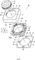
- FIG.1is an exploded oblique view of camera-shake correction apparatus 10.
- FIG.2is an exploded oblique view of auto-focusing lens drive apparatus 20 used in camera-shake correction apparatus 10 shown in FIG.1 .
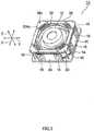
- FIG.3is an assembled oblique view, excluding shield cover 42, of camera-shake correction apparatus 10 shown in FIG.1 .
- orthogonal coordinate system(X,Y,Z) is used, as shown in FIG. through FIG.3 .
- the X-axis directionis the front-back direction (depth direction)
- the Y-axis directionis the horizontal direction (width direction)
- the Z-axis directionis the vertical-direction (height direction).
- vertical direction Zis the lens optical axis O direction.
- the X-axis direction (front-back direction)is also referred to as the first direction
- the Y-axis direction (horizontal direction)is also referred to as the second direction.
- the optical axis O direction --that is, the Z-axis direction --is the front-back direction.
- the upward Z-axis directionis the forward direction
- the downward Z-axis directionis the rearward direction.
- Camera-shake correction apparatus 10 illustratedis an apparatus that corrects camera shake (vibration) that occurs when a still image is captured with a small camera for mobile phone use, and enables a blur-free image to be captured.
- Camera-shake correction apparatus 10corrects camera shake by moving the entirety of auto-focusing lens drive apparatus 20 in first direction (front-back direction) X and second direction (horizontal direction) Y that are perpendicular to optical axis O and are perpendicular to each other.
- Auto-focusing lens drive apparatus 20is for moving lens barrel 12 along optical axis O.
- Base printed wiring board (base) 14is disposed so as to be spaced from the bottom surface of auto-focusing lens drive apparatus 20.
- an imaging device disposed on an imaging boardis mounted on the bottom (rear part) of this base printed wiring board 14.
- This imaging devicecaptures a subject image formed by means of lens barrel 12, and converts this subject image to an electrical signal.
- the imaging devicecomprises, for example, a CCD (charge coupled device) image sensor, CMOS (complementary metal oxide semiconductor) image sensor, or the like. Therefore, a camera module is configured by combining lens drive apparatus 20, an imaging board, and an imaging device.
- Auto-focusing lens drive apparatus 20is provided with lens holder 24 having tubular section 240 for holding lens barrel 12, focusing coil 26 fixed to this lens holder 24 so as to be positioned around tubular section 240, magnet holder 30 that holds permanent magnet 28 disposed on the outside of this focusing coil 26, facing focusing coil 26, and a pair of leaf springs 32 and 34 provided on either side of optical axis O of tubular section 240 of lens holder 24.
- the pair of leaf springs 32 and 34support lens holder 24 so as to be displaceable in the optical axis O direction when lens holder 24 is positioned in a radial direction.
- leaf spring 32is referred to as the upper leaf spring
- leaf spring 34is referred to as the lower leaf spring.
- upper leaf spring 32is also referred to as the front spring
- lower leaf spring 34is also referred to as the rear spring.
- Magnet holder 30is of octagonally tubular shape. That is to say, magnet holder 30 has octagonally tubular outer tube section 302, octagonal upper ring-shaped end section 304 provided on the top (front) of this outer tube section 302, and octagonal lower ring-shaped end 306 provided on the bottom (rear) of outer tube section 302. Upper ring-shaped end section 304 has eight upper projections 304a projecting upward, and lower ring-shaped end 306 has eight lower projections 306a projecting downward.
- Focusing coil 26is of octagonally tubular shape matching the shape of octagonally tubular magnet holder 30.
- Permanent magnet 28includes four permanent magnet sections 282 disposed on octagonally tubular outer tube section 302 of magnet holder 30 so as to be spaced from each other in first direction (front-back direction) X and second direction (horizontal direction) Y. In any event, permanent magnet 28 is disposed spaced from focusing coil 26.
- Upper leaf spring (front spring) 32is disposed above (forward) in the optical axis O direction in lens holder 24, and lower leaf spring (rear spring) 34 is disposed below (rearward) in the optical axis O direction in lens holder 24.
- Upper leaf spring (front spring) 32 and lower leaf spring (rear spring) 34have almost identical configurations.
- Upper leaf spring (front spring) 32has upper inner ring section 322 attached to the top of lens holder 24, and upper outer ring section 324 attached to upper ring-shaped end section 304 of magnet holder 30.
- Four upper arm sections 326are provided between upper inner ring section 322 and upper outer ring section 324. That is to say, four upper arm sections 326 link upper inner ring section 322 and upper outer ring section 324.
- Upper outer ring section 324has eight engaging notches 324a that engage respectively with eight upper projections 304a of magnet holder 30.
- Ring-shaped upper printed wiring board (upper board) 36is disposed on the top of upper leaf spring (front spring) 32.
- Upper printed wiring board (upper board) 36has eight upper board holes 36a into which eight upper projections 304a of magnet holder 30 are pressed (inserted) respectively. That is to say, eight upper projections 304a of magnet holder 30 are pressed (inserted) respectively into eight upper board holes 36a of ring-shaped upper printed wiring board (upper board) 36 via eight engaging notches 324a of upper outer ring section 324. That is to say, upper outer ring section 324 of upper leaf spring (front spring) 32 is fixed by being sandwiched between upper ring-shaped end section 304 of magnet holder 30 and ring-shaped upper printed wiring board 36.
- lower leaf spring (rear spring) 34has a lower inner ring section (not illustrated) attached to the bottom of lens holder 24, and lower outer ring section 344 attached to lower ring-shaped end 306 of magnet holder 30.
- Four lower arm sections(not illustrated) are provided between the lower inner ring section and lower outer ring section 344. That is to say, four lower arm sections link the lower inner ring section and lower outer ring section 344.
- Lower outer ring section 344has eight lower engaging notches 344a that engage respectively with eight lower projections 306a of magnet holder 30.
- Ring-shaped stopper 38is disposed on the bottom of lower leaf spring (rear spring) 34.
- Stopper 38has eight stopper notches 38a into which eight lower projections 306a of magnet holder 30 are pressed (inserted) respectively. That is to say, eight lower projections 306a of magnet holder 30 are pressed (inserted) respectively into eight stopper notches 38a of stopper 38 via eight engaging notches 344a of lower outer ring section 344. That is to say, lower outer ring section 344 of lower leaf spring (rear spring) 34 is fixed by being sandwiched between lower ring-shaped end 306 of magnet holder 30 and stopper 38.
- the elastic memberscomprising upper leaf spring 32 and lower leaf spring 34 function as guide sections that guide lens holder 24 so as to be able to move only in the optical axis O direction.
- Upper leaf spring 32 and lower leaf spring 34are made of beryllium copper, phosphor bronze, or the like.
- Internal thread 242is cut into the inner peripheral wall of tubular section 240 of lens holder 24, and external thread 122 that is screwed into above internal thread 242 is cut into the outer peripheral wall of lens barrel 12. Therefore, to fit lens barrel 12 into lens holder 24, lens barrel 12 is accommodated inside lens holder 24 by turning lens barrel 12 about optical axis O and screwing lens barrel 12 into tubular section 240 of lens holder 24 in the optical axis O direction, and they are joined together by means of adhesive or the like.
- Camera-shake correction apparatus 10will now be described with reference to FIG.1 and FIG.3 .
- Camera-shake correction apparatus 10has four suspension wires 16 that each have one end fixed to one of the four corners of base printed wiring board (base) 14, and camera-shake correction coils 18 disposed on the outside of permanent magnet 28 of above auto-focusing lens drive apparatus 20, facing permanent magnet 28.
- suspension wires 16extend along optical axis O, and support the entirety of auto-focusing lens drive apparatus 20 so as to be able to rock in first direction (front-back direction) X and second direction (horizontal direction) Y.
- the other ends of four suspension wires 16are fixed to upper printed wiring board 36 of above auto-focusing lens drive apparatus 20.
- upper printed wiring board 36has four wire fixing holes 36b into which the other ends of four suspension wires 16 are inserted.
- the other ends of four suspension wires 16are inserted into these four wire fixing holes 36b, and are fixed with adhesive, solder, or the like.
- Two of four suspension wires 16are used to supply power to focusing coil 26.
- permanent magnet 28includes four permanent magnet sections 282 disposed so as to face each other in first direction (front-back direction) X and second direction (horizontal direction) Y.
- Camera-shake correction apparatus 10is provided with four coil boards 40 disposed so as to face and be spaced from four permanent magnet sections 282 respectively. Above camera-shake correction coils 18 are formed on these four coil boards 40.
- a pair of camera-shake correction coils 18are formed at either end of each coil board 40. Therefore, there are a total of eight camera-shake correction coils 18.
- Four camera-shake correction coils 18 formed on two coil boards 40 disposed so as to face each other in second direction (horizontal direction) Yare for moving (rocking) auto-focusing lens drive apparatus 20 in first direction (front-back direction) X.
- first-direction actuator 18 (1)These four camera-shake correction coils 18 are referred to as first-direction actuator 18 (1).
- four camera-shake correction coils 18 formed on two coil boards 40 disposed so as to face each other in first direction (front-back direction) Xare for moving (rocking) auto-focusing lens drive apparatus 20 in second direction (horizontal direction) Y.
- These four camera-shake correction coils 18are referred to as second-direction actuator 18 (2).
- camera-shake correction coils 18are for driving the entirety of auto-focusing lens drive apparatus 20 in the X-axis direction (first direction) and Y-axis direction second direction) in collaboration with permanent magnet 28. Also, the combination of camera-shake correction coils 18 and permanent magnet 28 functions as a voice coil motor (VCM).
- VCMvoice coil motor
- camera-shake correction apparatus 10 illustratedcorrects camera shake by moving lens barrel 12 itself, housed in auto-focusing lens drive apparatus 20, in first direction (front-back direction) X and second direction (horizontal direction) Y. Therefore, camera-shake correction apparatus 10 is referred to as a "barrel-shifting" camera-shake correction apparatus.
- Camera-shake correction apparatus 10is also provided with shield cover 42 that includes square tubular section 422 covering four coil boards 40.
- shield cover 42that includes square tubular section 422 covering four coil boards 40.
- four coil boards 40are attached to the inner wall of square tubular section 422 of shield cover 42 as shown in FIG.1 .
- Camera-shake correction apparatus 10 illustratedis also provided with position detection section 50 for detecting the position of auto-focusing lens drive apparatus 20 with respect to base printed wiring board 14.
- Position detection section 50 illustratedcomprises four Hall devices 50 mounted on base printed wiring board 14. These four Hall devices 50 are disposed facing and spaced from four permanent magnet sections 282.
- a pair of Hall devices 50 disposed facing in first direction (front-back direction) Xdetect a first position associated with first direction (front-back direction) X movement (rocking) by detecting magnetic force of a pair of permanent magnet sections 282 facing them.
- a pair of Hall devices 50 disposed facing in second direction (horizontal direction) Ydetect a second position associated with second direction (horizontal direction) Y movement (rocking) by detecting magnetic force of a pair of permanent magnet sections 282 facing them.
- FIG.4is a block diagram showing the configuration of camera-shake correction actuator 600 that controls camera-shake correction apparatus 10.
- Camera-shake correction apparatus 10is installed in a camera-equipped mobile phone (not illustrated).
- the housing of a camera-equipped mobile phone(not illustrated) is provided with first-direction gyroscope 602 for detecting first direction (front-back direction) X shake, and second-direction gyroscope 604 for detecting second direction (horizontal direction) Y shake.
- First-direction gyroscope 602detects first direction (front-back direction) X angular velocity, and outputs a first angular velocity signal representing the detected first direction (front-back direction) X angular velocity.
- Second-direction gyroscope 604detects second direction (horizontal direction) Y angular velocity, and outputs a second angular velocity signal representing the detected second direction (horizontal direction) Y angular velocity.
- the first and second angular velocity signalsare supplied to shake correction control section 606.
- a shutter operation command signalis supplied to shake correction control section 606 from shutter button 608.
- Shake correction control section 606has shake detection circuit 612 that detects shake of the camera-equipped mobile phone housing from the first and second angular velocity detection signals, and sequence control circuit 614 that receives a shutter operation command signal.
- Shake detection circuit 612includes a filter circuit and amplifier circuit.
- Shake detection circuit 612supplies a shake detection signal to shake amount detection circuit 616.
- Shake amount detection circuit 616detects a shake amount of the camera-equipped mobile phone housing from the shake detection signal, and sends a shake amount detection signal to coefficient conversion circuit 618.
- Coefficient conversion circuit 618performs coefficient conversion of the shake amount detection signal, and sends a coefficient-converted signal to control circuit 620.
- a position detection signal from position detection section (position sensor) 50 provided in camera-shake correction apparatus 10is supplied to this control circuit 620.
- control circuit 620In response to the coefficient-converted signal, control circuit 620 outputs a control signal so as to cancel out shake detected by shake detection circuit 612 based on the position detection signals.
- sequence control circuit 614controls the timing of shake amount detection circuit 616, coefficient conversion circuit 618, and control circuit 620. The control signal is supplied to drive circuit 622.
- camera-shake correction apparatus 10is provided with first-direction actuator 18 (1) for moving (rocking) the entirety of auto-focusing lens drive apparatus 20 in first direction (front-back direction) X, and second-direction actuator 18 (2) for moving (rocking) the entirety of auto-focusing lens drive apparatus 20 in second direction (horizontal direction) Y, as voice coil motors.
- camera-shake correction apparatus 10includes first-direction actuator 18 (1) and second-direction actuator 18 (2).
- Drive circuit 622drives first-direction actuator 18 (1) and second-direction actuator 18 (2) in response to a control signal.
- camera-shake correction apparatus 10can move (rock) the entirety of auto-focusing lens drive apparatus 20 so as to cancel out shake of a camera-equipped mobile phone housing. As a result, camera shake can be corrected.
- Camera-shake correction apparatus 10according to a first embodiment of the present invention as described above achieves the following effects.
- auto-focusing lens drive apparatus 20is provided with camera-shake correction apparatus 10, and permanent magnet 28 is used in common, the number of component parts can be reduced. As a result, the size (mainly the height) of camera-shake correction apparatus 10 can be made smaller (lower).
- a barrel-shifting methodenables the size (mainly the height) of camera-shake correction apparatus 10 to be made virtually the same that of auto-focusing lens drive apparatus 20.
- camera-shake correction apparatus 10 according to this first embodimentit is possible for camera-shake correction apparatus 10 according to this first embodiment to be installed in an optical camera-shake correcting camera for mobile phone use.
- a magnetic position detection sectioncomprising Hall devices 50 is used as a position detection section (position sensor), but another position detection section (position sensor) such as a photoreflector or suchlike optical position detection section may be used instead of Hall devices 50.
- permanent magnet 28comprises four permanent magnet sections 282 disposed so as to face each other in first direction X and second direction Y, but the number of permanent magnet sections is not limited to four, and, for example, eight sections may be used that are disposed facing in diagonal directions rather than in only a first and second direction. In this case, the number of camera-shake correction coils 18 and the number of coil boards 40 are also changed in line with the number of permanent magnet sections 288. Furthermore, in the above-described first embodiment, one end of each of four suspension wires 16 is fixed to one of the four corners of base 14, but these ends may also be fixed to the outer periphery of base 14. Moreover, the number of suspension wires 16 is not limited to four, and may be any plurality.
- FIG.5is an external oblique view of camera-shake correction apparatus 10A.
- FIG.6is a vertical cross-sectional view of camera-shake correction apparatus 10A.
- FIG.7is an exploded oblique view of camera-shake correction apparatus 10A.
- FIG.8is an exploded oblique view of auto-focusing lens drive apparatus 20A used in camera-shake correction apparatus 10A shown in FIG.5 .
- orthogonal coordinate system(X,Y,Z) is used, as shown in FIG.5 through FIG.8 .
- the X-axis directionis the front-back direction (depth direction)
- the Y-axis directionis the horizontal direction (width direction)
- the Z-axis directionis the vertical-direction (height direction).
- vertical direction Zis the lens optical axis O direction.
- the X-axis direction (front-back direction)is also referred to as the first direction
- the Y-axis direction (horizontal direction)is also referred to as the second direction.
- the optical axis O direction -- that is, the Z-axis direction --is the front-back direction.
- the upward Z-axis directionis the forward direction
- the downward Z-axis directionis the rearward direction.
- Camera-shake correction apparatus 10A illustratedis an apparatus that corrects camera shake (vibration) that occurs when a still image is captured with a small camera for mobile phone use, and enables a blur-free image to be captured.
- Camera-shake correction apparatus 10Acorrects camera shake by moving the entirety of auto-focusing lens drive apparatus 20A in first direction (front-back direction) X and second direction (horizontal direction) Y that are perpendicular to optical axis O and are perpendicular to each other.
- Auto-focusing lens drive apparatus 20Ais for moving lens barrel 12A along optical axis O.
- Base 14Ais disposed so as to be spaced from the bottom surface of auto-focusing lens drive apparatus 20A.
- an imaging device disposed on an imaging boardis mounted on the bottom (rear part) of this base 14A.
- This imaging devicecaptures a subject image formed by means of lens barrel 12A, and converts this subject image to an electrical signal.
- the imaging devicecomprises, for example, a CCD (charge coupled device) image sensor, CMOS (complementary metal oxide semiconductor) image sensor, or the like. Therefore, a camera module is configured by combining lens drive apparatus 20A, an imaging board, and an imaging device.
- Base 14Acomprises ring-shaped base section 142A of square external shape and having a circular aperture inside, and square-tube-shaped tubular section 144A that projects in the upward optical axis O direction from the outer edge of this base section 142A.
- Camera-shake correction apparatus 10Ahas four suspension wires 16A that each have one end fixed to one of the four corners of base section 142A of base 14A, and camera-shake correction coils 18A disposed so as to face permanent magnet 28A of auto-focusing lens drive apparatus 20A described later herein in a manner described later herein.
- suspension wires 16Aextend along optical axis O, and support the entirety of auto-focusing lens drive apparatus 20A so as to be able to rock in first direction (front-back direction) X and second direction (horizontal direction) Y.
- the other ends of four suspension wires 16Aare fixed to the upper end of above auto-focusing lens drive apparatus 20A as described later herein.
- camera-shake correction apparatus 10Ais provided with one square-ring-shaped coil board 40A disposed so as to face and be spaced from permanent magnet 28A.
- This coil board 40Ais attached to the upper end of tubular section 144A of base 14A.
- Above camera-shake correction coils 18Aare formed on this coil board 40A.
- Auto-focusing lens drive apparatus 20Ais provided with lens holder 24A having tubular section 240A for holding lens barrel 12A, first and second focusing coils 26A-1 and 26A-2 fixed to this lens holder 24A so as to be positioned around tubular section 240A, magnet holder 30A that holds permanent magnet 28A disposed on the outside of first and second focusing coils 26A-1 and 26A-2, facing first and second focusing coils 26A-1 and 26A-2, and a pair of leaf springs 32A and 34A provided on either side of optical axis O of tubular section 240A of lens holder 24A.
- First focusing coil 26A-1is installed in the upper optical axis O direction of tubular section 240A of lens holder 24A
- second focusing coil 26A-2is installed in the lower optical axis O direction of tubular section 240A of lens holder 24A.
- the pair of leaf springs 32A and 34Asupport lens holder 24A so as to be displaceable in the optical axis O direction when lens holder 24A is positioned in a radial direction.
- leaf spring 32Ais referred to as the upper leaf spring
- leaf spring 34Ais referred to as the lower leaf spring.
- upper leaf spring 32Ais also referred to as the front spring
- lower leaf spring 34Ais also referred to as the rear spring.
- Magnet holder 30Ais of octagonally tubular shape. That is to say, magnet holder 30A has octagonally tubular outer tube section 302A, square upper ring-shaped end section 304A provided on the top (front) of this outer tube section 302A, and octagonal lower ring-shaped end 306A provided on the bottom (rear) of outer tube section 302A.
- First and second focusing coils 26A-1 and 26A-2are each of octagonally tubular shape matching the shape of octagonally tubular magnet holder 30A.
- Permanent magnet 28Acomprises eight rectangular permanent magnet sections disposed on octagonally tubular outer tube section 302A of magnet holder 30a so as to be spaced from each other in first direction (front-back direction) X, second direction (horizontal direction) Y, and vertical direction Z. Of these eight rectangular permanent magnet sections, four first permanent magnet sections 282A-1 are disposed in the upper optical axis O direction of outer tube section 302A, and remaining four second permanent magnet sections 282A-2 are disposed in the lower optical axis O direction of outer tube section 302A. Four first permanent magnet sections 282A-1 are disposed spaced from first focusing coil 26A-1, and four second permanent magnet sections 282A-2 are disposed spaced from second focusing coil 26A-2.
- Upper leaf spring (front spring) 32Ais disposed above (forward) in the optical axis O direction in lens holder 24A, and lower leaf spring (rear spring) 34A is disposed below (rearward) in the optical axis O direction in lens holder 24A.
- Upper leaf spring (front spring) 32A and lower leaf spring (rear spring) 34Ahave almost identical configurations.
- Upper leaf spring (front spring) 32Ahas upper inner ring section 322A attached to the top of lens holder 24A, and upper outer ring section 324A attached to upper ring-shaped end section 304A of magnet holder 30A.
- Four upper arm sections 326Aare provided between upper inner ring section 322A and upper outer ring section 324A. That is to say, four upper arm sections 326A link upper inner ring section 322A and upper outer ring section 324A.
- Upper outer ring section 324Ahas four wire fixing holes 324Aa into which the other ends of above four suspension wires 16A are inserted.
- lower leaf spring (rear spring) 34Ahas lower inner ring section 342A attached to the bottom of lens holder 24A, and lower outer ring section 344A attached to lower ring-shaped end 306A of magnet holder 30A.
- Four lower arm sections 346Aare provided between lower inner ring section 342A and upper outer ring section 344A. That is to say, four lower arm sections 346A link lower inner ring section 342A and lower outer ring section 344A.
- the elastic memberscomprising upper leaf spring 32A and lower leaf spring 34A function as guide sections that guide lens holder 24A so as to be able to move only in the optical axis O direction.
- Upper leaf spring 32A and lower leaf spring 34Aare made of beryllium copper, phosphor bronze, or the like.
- lens barrel 12Ais accommodated inside lens holder 24A by turning lens barrel 12A about optical axis O and screwing lens barrel 12A into tubular section 240A of lens holder 24A in the optical axis O direction, and they are joined together by means of adhesive or the like.
- first and second auto-focusing (AF) currentsBy passing first and second auto-focusing (AF) currents through first and second focusing coils 26A-1 and 26A-2 respectively as described later herein, it is possible to adjust the position of lens holder 24A (lens barrel 12A) in the optical axis O direction through the mutual action of the magnetic field of permanent magnet 28A and magnetic fields by the AF currents flowing through first and second focusing coils 26A-1 and 26A-2.
- AFauto-focusing
- Camera-shake correction apparatus 10Awill now be described in further detail with reference to FIG.6 and FIG.7 .
- camera-shake correction apparatus 10Ahas four suspension wires 16A that each have one end fixed to one of the four corners of base section 142A of base 14A, and camera-shake correction coils 18A disposed on the outside of permanent magnet 28A of above auto-focusing lens drive apparatus 20A, facing permanent magnet 28A.
- suspension wires 16Aextend along optical axis O, and support the entirety of auto-focusing lens drive apparatus 20A so as to be able to rock in first direction (front-back direction) X and second direction (horizontal direction) Y.
- the other ends of four suspension wires 16Aare fixed to the top of above auto-focusing lens drive apparatus 20A.
- upper outer ring section 324Ahas four wire fixing holes 324Aa into which the other ends of four suspension wires 16A are inserted (see FIG.8 ).
- upper ring-shaped end section 304A of magnet holder 30Ahas four wire insertion holes 304Aa into which the other ends of four suspension wires 16A are inserted (see FIG.8 ). The other ends of four suspension wires 16A are inserted into four wire fixing holes 324Aa via these four wire insertion holes 304Aa, and are fixed with adhesive, solder, or the like.
- suspension wires 16Aare used to supply current to first and second focusing coils 26A-1 and 26A-2.
- permanent magnet 28Acomprises four first permanent magnet sections 282A-1 and four second permanent magnet sections 282A-2 disposed so as to face each other in first direction (front-back direction) X and second direction (horizontal direction) Y, and to be spaced vertically in the optical axis O direction.
- Camera-shake correction apparatus 10Ais provided with one square-ring-shaped coil board 40A disposed so as to be inserted between and spaced from four first permanent magnet sections 282A-1 and four second permanent magnet sections 282A-2.
- Coil board 40Ahas through-holes 40Aa at its four corners for the passage of four suspension wires 16A.
- Above camera-shake correction coils 18Aare formed on this one coil board 40A.
- camera-shake correction coils 18Af, 18Ab, 18A1, and 18Arare formed on coil board 40A as camera-shake correction coils 18A (see FIG.9 ).
- Two camera-shake correction coils 18Af and 18Ab disposed so as to face each other in first direction (front-back direction) Xare for moving (rocking) auto-focusing lens drive apparatus 20A in first direction (front-back direction) X.
- These two camera-shake correction coils 18Af and 18Abare referred to as the first-direction actuator.
- camera-shake correction coil 18Af located forward with respect to optical axis Ois referred to as the "front camera-shake correction coil”
- camera-shake correction coil 18Ab located rearward with respect to optical axis Ois referred to as the "back camera-shake correction coil.”
- two camera-shake correction coils 18A1 and 18Ar disposed so as to face each other in second direction (horizontal direction) Yare for moving (rocking) auto-focusing lens drive apparatus 20A in second direction (horizontal direction) Y.
- These two camera-shake correction coils 18A1 and 18Arare referred to as the second-direction actuator.
- camera-shake correction coil 18A1 located leftward with respect to optical axis Ois referred to as the "left camera-shake correction coil”
- camera-shake correction coil 18Ar located rightward with respect to optical axis Ois referred to as the "right camera-shake correction coil.”
- four camera-shake correction coils 18Af, 18Ab, 18A1, and 18Arare for driving the entirety of auto-focusing lens drive apparatus 20A in the X-axis direction (first direction) and Y-axis direction second direction) in collaboration with permanent magnet 28A. Also, the combination of four camera-shake correction coils 18Af, 18Ab, 18A1, and 18Ar and permanent magnet 28A functions as a voice coil motor (VCM).
- VCMvoice coil motor
- camera-shake correction apparatus 10A illustratedcorrects camera shake by moving lens barrel 12A itself, housed in auto-focusing lens drive apparatus 20A, in first direction (front-back direction) X and second direction (horizontal direction) Y. Therefore, camera-shake correction apparatus 10A is referred to as a "barrel-shifting" camera-shake correction apparatus.
- Camera-shake correction apparatus 10Ais also provided with cover 42A that includes square tubular section 422A covering the upper part (four first permanent magnet sections 282A-1) of auto-focusing lens drive apparatus 20A.
- Position detection section 50A illustratedcomprises a magnetic position detection section composed of two Hall devices 50A mounted on base section 142A of base 14A. These two Hall devices 50A are disposed facing and spaced from two of four second permanent magnet sections 282A-2. As shown in FIG.10 , Hall devices 50A are disposed so as to intersect the direction from the N pole to the S pole in second permanent magnet sections 282A-2.
- One Hall device 50A disposed in first direction (front-back direction) X with respect to optical axis Odetects a first position associated with first direction (front-back direction) X movement (rocking) by detecting magnetic force of one second permanent magnet section 282A-2 facing it.
- One Hall device 50A disposed in second direction (horizontal direction) Y with respect to optical axis Odetects a second position associated with second direction (horizontal direction) Y movement (rocking) by detecting magnetic force of one second permanent magnet section 282A-2 facing it.
- a magnetic position detection sectioncomprising two Hall devices 50A is used as position detection section 50A, but a magnetic position detection section comprising four Hall devices 50 may also be used, as in camera-shake correction apparatus 10 according to the first embodiment described earlier.
- FIG.9is an oblique view of the magnetic circuit
- FIG.10is a vertical cross-sectional view of the magnetic circuit
- FIG.1 1is a plan view with four first permanent magnet sections 282A-2 and first focusing coil 26A-1 omitted from the magnetic circuit.
- first permanent magnet sections 282A-1 and four second permanent magnet sections 282A-2have different adjacent pole magnetization in outward and inward radial directions of lens holder 24A.
- first permanent magnet sections 282A-1have inward S pole magnetization and outward N pole magnetization
- four second permanent magnet sections 282A-2have outward S pole magnetization and inward N pole magnetization.
- the arrows in FIG.10indicate the directions of magnetic flux generated by these permanent magnet sections 282A-1 and 282A-2.
- a first AF current and second AF currentflow in different directions from each other in first focusing coil 26A-1 and second focusing coil 26A-2 respectively.
- a first AF currentflows in a clockwise direction as indicated by arrow I AF1
- a second AF currentflows in a counterclockwise direction as indicated by arrow I AF2 .
- lens holder 24A(lens barrel 12A) can be moved in the downward optical axis O direction.
- a left-direction magnetic forceacts on left camera-shake correction coil 18Al
- a left-direction magnetic forcealso acts on right camera-shake correction coil 18Ar.
- right-direction magnetic forcesas indicated by arrows F IS1 and F IS2 in FIG.11 act on the entirety of auto-focusing lens drive apparatus 20A.
- the entirety of auto-focusing lens drive apparatus 20Acan be moved in a rightward direction.
- Camera-shake correction apparatus 10Aaccording to a second embodiment of the present invention as described above achieves the following effects.
- auto-focusing lens drive apparatus 20Ais provided with camera-shake correction apparatus 10A, and permanent magnet 28A is used in common, the number of component parts can be reduced. As a result, the size (mainly the height) of camera-shake correction apparatus 10A can be made smaller (lower).
- a barrel-shifting methodenables the size (mainly the height) of camera-shake correction apparatus 10A to be made virtually the same that of auto-focusing lens drive apparatus 20A.
- camera-shake correction apparatus 10A according to this second embodimentit is possible for camera-shake correction apparatus 10A according to this second embodiment to be installed in an optical camera-shake correcting camera for mobile phone use.
- camera-shake correction coils 18Aare disposed between upper four first permanent magnet sections 282A-1 and lower four second permanent magnet sections 282A-2, it is possible to implement highly sensitive actuators.
- a magnetic position detection sectioncomprising two Hall devices 50A is used as a position detection section (position sensor), but another position detection section (position sensor) such as a photoreflector or suchlike optical position detection section may be used instead of Hall devices 50A.
- permanent magnet 28Acomprises four first permanent magnet sections 282A-1 and four second permanent magnet sections 282A-2 disposed so as to face each other in first direction X and second direction Y, and to be spaced vertically in the optical axis O direction, but the number of first permanent magnet sections and second permanent magnet sections is not limited to four each, and, for example, eight sections may be used that are disposed facing in diagonal directions rather than in only a first and second direction. In this case, the number of camera-shake correction coils 18A is also changed to eight.
- suspension wires 16Arise up from the four corners of base section 142A of base 14A, but these ends may also rise up from the outer periphery of base section 142A. Furthermore, the number of suspension wires 16A is not limited to four, and may be any plurality.
- Camera-shake correction apparatuses 10 and 10Ause a "moving magnet method” in which permanent magnets 18 and 18A are moved.
- a "moving coil method” in which a coil is movedmay also be used. By this means, moving parts of an auto-focusing lens drive apparatus can be made lighter.
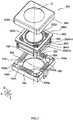
- FIG.12is an external oblique view of camera-shake correction apparatus 10B.
- FIG.13is a vertical cross-sectional view of camera-shake correction apparatus 10B.
- FIG.14is an exploded oblique view of camera-shake correction apparatus 10B.
- FIG.15is an exploded oblique view of auto-focusing lens drive apparatus 20B used in camera-shake correction apparatus 10B shown in FIG.12 .
- orthogonal coordinate system(X,Y,Z) is used, as shown in FIG.12 through FIG.15 .
- the X-axis directionis the front-back direction (depth direction)
- the Y-axis directionis the horizontal direction (width direction)
- the Z-axis directionis the vertical-direction (height direction).
- vertical direction Zis the lens optical axis O direction.
- the X-axis direction (front-back direction)is also referred to as the first direction
- the Y-axis direction (horizontal direction)is also referred to as the second direction.
- the optical axis O direction -- that is, the Z-axis direction --is the front-back direction.
- the upward Z-axis directionis the forward direction
- the downward Z-axis directionis the rearward direction.
- Camera-shake correction apparatus 10B illustratedis an apparatus that corrects camera shake (vibration) that occurs when a still image is captured with a small camera for mobile phone use, and enables a blur-free image to be captured.
- Camera-shake correction apparatus 10Bcorrects camera shake by moving a moving part of auto-focusing lens drive apparatus 20B in first direction (front-back direction) X and second direction (horizontal direction) Y that are perpendicular to optical axis O and are perpendicular to each other.
- Camera-shake correction apparatus 10B illustratedis a camera-shake correction apparatus that uses a "moving coil method.”
- Auto-focusing lens drive apparatus 20Bis for moving a lens barrel (not illustrated) along optical axis O.
- Base 14Bis disposed so as to be spaced from the bottom surface of auto-focusing lens drive apparatus 20B in an outward radial direction.
- an imaging device disposed on an imaging boardis mounted on the bottom (rear part) of this base 14B. This imaging device captures a subject image formed by means of the lens barrel, and converts this subject image to an electrical signal.
- the imaging devicecomprises, for example, a CCD (charge coupled device) image sensor, CMOS (complementary metal oxide semiconductor) image sensor, or the like. Therefore, a camera module is configured by combining lens drive apparatus 20B, an imaging board, and an imaging device.
- Base 14Bcomprises ring-shaped base section 142B of square external shape and having a circular aperture inside, and square-tube-shaped tubular section 144B having four rectangular apertures 144Ba that projects in the upward optical axis O direction from the outer edge of this base section 142B.
- Camera-shake correction apparatus 10Bhas eight suspension wires 16B, pairs of which each have one end fixed to one of the four corners of base section 142B of base 14B, and camera-shake correction coils 18B disposed so as to face permanent magnet 28B of auto-focusing lens drive apparatus 20B described later herein in a manner described later herein.
- Eight suspension wires 16Bextend along optical axis O, and support a moving part of auto-focusing lens drive apparatus 20B so as to be able to rock in first direction (front-back direction) X and second direction (horizontal direction) Y.
- the other ends of eight suspension wires 16Bare fixed to the upper end of above auto-focusing lens drive apparatus 20B as described later herein.
- camera-shake correction apparatus 10Bis provided with one square-ring-shaped coil board 40B disposed so as to face and be spaced from permanent magnet 28B. This coil board 40B is attached to coil holder 44B. Above camera-shake correction coils 18B are formed on this coil board 40B.
- Coil holder 44Bhas four pillar sections 442B extending in parallel to the optical axis O direction at its four corners, approximately square upper ring-shaped end 444B attached to the upper ends (front ends) of these four pillar sections 442B, and lower ring-shaped end 446B attached to the lower ends (rear ends) of four pillar sections 442B.
- Upper ring-shaped end 444Bhas four upper projections 444Ba projecting upward at its four corners
- lower ring-shaped end 446Balso has four lower projections 446Ba projecting upward.
- Auto-focusing lens drive apparatus 20Bis provided with lens holder 24B having tubular section 240B for holding a lens barrel, first and second focusing coils 26B-1 and 26B-2 fixed to this lens holder 24B so as to be positioned around tubular section 240B, four magnet holders 30B that hold permanent magnet 28B disposed on the outside of first and second focusing coils 26B-1 and 26B-2, facing first and second focusing coils 26B-1 and 26B-2, and a pair of leaf springs 32B and 34B provided on either side of optical axis O of tubular section 240B of lens holder 24B.
- First focusing coil 26B-1is installed in the upper optical axis O direction of tubular section 240B of lens holder 24B
- second focusing coil 26B-2is installed in the lower optical axis O direction of tubular section 240B of lens holder 24B.
- the pair of leaf springs 32B and 34Bsupport lens holder 24B so as to be displaceable in the optical axis O direction when lens holder 24B is positioned in a radial direction.
- leaf spring 32Bis referred to as the upper leaf spring
- leaf spring 34Bis referred to as the lower leaf spring.
- upper leaf spring 32Bis also referred to as the front spring
- lower leaf spring 34Bis also referred to as the rear spring.
- Permanent magnet 28Bcomprises eight rectangular permanent magnet sections disposed in pairs on four magnet holders 30B so as to be spaced from each other in first direction (front-back direction) X, second direction (horizontal direction) Y, and vertical direction Z. Of these eight rectangular permanent magnet sections, four first permanent magnet sections 282B-1 are disposed in the upper optical axis O direction of four magnet holders 30B, and remaining four second permanent magnet sections 282B-2 are disposed in the lower optical axis O direction of four magnet holders 30B. Four first permanent magnet sections 282B-1 are disposed spaced from first focusing coil 26B-1, and four second permanent magnet sections 282B-2 are disposed spaced from second focusing coil 26B-2.
- Upper leaf spring (front spring) 32Bis disposed above (forward) in the optical axis O direction in lens holder 24B, and lower leaf spring (rear spring) 34B is disposed below (rearward) in the optical axis O direction in lens holder 24B.
- Upper leaf spring (front spring) 32B and lower leaf spring (rear spring) 34Bhave almost identical configurations.
- Upper leaf spring (front spring) 32Bhas upper inner ring section 322A attached to the top of lens holder 24B, and upper outer ring section 324B attached to upper ring-shaped end 444B of coil holder 44B.
- Four upper arm sections 326Bare provided between upper inner ring section 322B and upper outer ring section 324B. That is to say, four upper arm sections 326B link upper inner ring section 322B and upper outer ring section 324B.
- Upper outer ring section 324Bhas four upper holes 324Ba into which four upper projections 444Ba of coil holder 44B are pressed (inserted and attached). That is to say, four upper projections 444Ba of coil holder 44B are pressed into (inserted into and attached inside) four upper holes 324Ba of upper outer ring section 324B of upper leaf spring 32B.
- tubular section 240B of lens holder 24Bhas four upper projections 240Ba on its upper end.
- Upper inner ring section 322Bhas four upper holes 322Ba into which these four upper projections 240Ba of tubular section 240B are pressed (inserted and attached). That is to say, four upper projections 240Ba of tubular section 240B of lens holder 24B are pressed into (inserted into and attached inside) four upper holes 322Ba of upper inner ring section 322B of upper leaf spring 32B.
- lower leaf spring (rear spring) 34Bhas lower inner ring section 342B attached to the bottom of lens holder 24B, and lower outer ring section 344B attached to lower ring-shaped end 446B of coil holder 44B.
- Four lower arm sections 346Bare provided between lower inner ring section 342B and upper outer ring section 344B. That is to say, four lower arm sections 346B link lower inner ring section 342B and lower outer ring section 344B.
- Lower outer ring section 344Bhas four lower holes 344Ba into which four lower projections 446Ba of coil holder 44B are pressed (inserted and attached). That is to say, four lower projections 446Ba of coil holder 44B are pressed into (inserted into and attached inside) four lower holes 344Ba of lower outer ring section 344B of lower leaf spring 34B.
- the elastic memberscomprising upper leaf spring 32B and lower leaf spring 34B function as guide sections that guide lens holder 24B so as to be able to move only in the optical axis O direction.
- Upper leaf spring 32B and lower leaf spring 34Bare made of beryllium copper, phosphor bronze, or the like.
- an internal thread(not illustrated) is cut into the inner peripheral wall of tubular section 240B of lens holder 24B, and an external thread (not illustrated) that is screwed into the above internal thread is cut into the outer peripheral wall of the lens barrel. Therefore, to fit the lens barrel into lens holder 24B, the lens barrel is accommodated inside lens holder 24B by turning the lens barrel about optical axis O and screwing the lens barrel into tubular section 240B of lens holder 24B in the optical axis O direction, and they are joined together by means of adhesive or the like.
- first and second auto-focusing (AF) currentsBy passing first and second auto-focusing (AF) currents through first and second focusing coils 26B-1 and 26B-2 respectively, it is possible to adjust the position of lens holder 24B (the lens barrel) in the optical axis O direction through the mutual action of the magnetic field of permanent magnet 28B and magnetic fields by the first and second AF currents flowing through first and second focusing coils 26B-1 and 26B-2.
- AFauto-focusing
- Camera-shake correction apparatus 10Bwill now be described in further detail with reference to FIG.13 and FIG.14 .
- camera-shake correction apparatus 10Bhas eight suspension wires 16B, pairs of which each have one end fixed to one of the four corners of base section 142B of base 14B, and camera-shake correction coils 18B disposed so as to face permanent magnet 28B of above-described auto-focusing lens drive apparatus 20B.
- base section 142Bhas eight wire fixing holes 142Ba, disposed in pairs in its four corners, into each of which one end of one of eight suspension wires 16B is inserted.
- Eight suspension wires 16Bextend along optical axis O, and support a moving part of auto-focusing lens drive apparatus 20B so as to be able to rock in first direction (front-back direction) X and second direction (horizontal direction) Y. The other ends of eight suspension wires 16B are fixed to the top of above auto-focusing lens drive apparatus 20B.
- coil holder 44Bfurther has four projecting sections 448B projecting in an outward radial direction at the four corners of upper ring-shaped end 444B (see FIG.15 ).
- Each of four projecting sections 448Bhas two wire fixing holes 448Ba into which the other ends of two suspension wires 16B are inserted. Therefore, the other ends of eight suspension wires 16B are inserted into these eight wire fixing holes 448Ba, and are fixed with adhesive, solder, or the like.
- the reason why the number of suspension wires 16B is eight in this third embodimentis that current is supplied to first and second focusing coils 26B-1 and 26B-2, and camera-shake correction coils 18B, via these eight suspension wires 16B.
- permanent magnet 28Bcomprises four first permanent magnet sections 282B-1 and four second permanent magnet sections 282B-2 disposed so as to face each other in first direction (front-back direction) X and second direction (horizontal direction) Y, and so as to be spaced vertically in the optical axis O direction.
- Camera-sbake correction apparatus 10Bis provided with one ring-shaped coil board 40B disposed so as to be inserted between and spaced from four first permanent magnet sections 282B-1 and four second permanent magnet sections 282B-2. Above camera-shake correction coils 18B are formed on this one coil board 40B.
- four camera-shake correction coils 18Bare formed on coil board 40B.
- Two camera-shake correction coils 18B disposed so as to face each other in first direction (front-back direction) Xare for moving (rocking) a moving part of auto-focusing lens drive apparatus 20B in first direction (front-back direction) X. These two camera-shake correction coils 18B are referred to as the first-direction actuator.
- two camera-shake correction coils 18B disposed so as to face each other in second direction (horizontal direction) Yare for moving (rocking) a moving part of auto-focusing lens drive apparatus 20B in second direction (horizontal direction) Y.
- These two camera-shake correction coils 18Bare referred to as the second-direction actuator.
- camera-shake correction coils 18Bare for driving a moving part of auto-focusing lens drive apparatus 20B in the X-axis direction (first direction) and Y-axis direction second direction) in collaboration with permanent magnet 28B. Also, the combination of camera-shake correction coils 18B and permanent magnet 28B functions as a voice coil motor (VCM).
- VCMvoice coil motor
- camera-shake correction apparatus 10B illustratedcorrects camera shake by moving the lens barrel itself, housed in auto-focusing lens drive apparatus 20B, in first direction (front-back direction) X and second direction (horizontal direction) Y. Therefore, camera-shake correction apparatus 10B is referred to as a "barrel-shifting" camera-shake correction apparatus.
- Camera-shake correction apparatus 10Bis also provided with cover 42 covering the upper part of auto-focusing lens drive apparatus 20B.
- camera-shake correction apparatus 10Bis also provided with position detection section (50B, 51B) for detecting the position of a moving part of auto-focusing lens drive apparatus 20B with respect to base 14B.
- position detection section (50B, 51B) illustratedcomprises an optical position detection section.
- Position detection section (50B, 51B)comprises two position detectors, each of which comprises photoreflector 50B and position information section 51B disposed facing each other.
- Two position information sections 51Bare disposed in first direction X and second direction Y on the underside of lower ring-shaped end 446B of coil holder 44B (in FIG.13 , only one position information section disposed in second direction Y is illustrated).
- each position information section 51Bcomprises reflective tape (a reflective seal), and is affixed to the underside of lower ring-shaped end 446B.
- Reflective tape 51Bhas a pattern in which a reference position is made a boundary in first direction X or second direction Y, and black and white/light and dark are clearly distinguishable.
- two photoreflectors 50Bare mounted on base section 142B of base 14B as shown in FIG.14 .
- Two photoreflectors 50Bare disposed spaced from and facing two position information sections 51B.
- One photoreflector 50B disposed in first direction (front-back direction) X with respect to optical axis Odetects a first position associated with first direction (front-back direction) X movement (rocking) as a voltage level by receiving reflected light from one position information section 51B (detecting the light intensity of the reflected light) by intersecting the light and dark of that position information section 51B facing that photoreflector 50B, as shown by the arrow in FIG.16 .
- One photoreflector 50B disposed in second direction (horizontal direction) Y with respect to optical axis Odetects a second position associated with second direction (horizontal direction) Y movement (rocking) as a voltage level by receiving reflected light from one position information section 51B (detecting the light intensity of the reflected light) by intersecting the light and dark of that position information section 51B facing that photoreflector 50B, as shown by the arrow in FIG.16 .
- an optical position detection section that includes two photoreflectors 50Bis used as position detection section 50B, but an optical position detection section that includes four photoreflectors may also be used.
- the position information section 51B patternis not limited to a black-and-white light-and-dark (binary) pattern, and various kinds of patterns may be used, such as a continuous pattern using gradations, or a continuous pattern using area ratio variation.
- camera-shake correction apparatus 10Bhaving this kind of configuration, operation when the position of lens holder 24B (the lens barrel) is adjusted in the optical axis O direction is similar to that of camera-shake correction apparatus 10A according to the second embodiment described with reference to FIG.9 , and therefore a description thereof is omitted here. Also, operation when a moving part of auto-focusing lens drive apparatus 20B is moved in first direction (front-back direction) X or second direction (horizontal direction) Y is similar to that of camera-shake correction apparatus 10A according to the second embodiment described with reference to FIG.1 1 , and therefore a description thereof is omitted here.
- Camera-shake correction apparatus 10Baccording to a third embodiment of the present invention as described above achieves the following effects.
- auto-focusing lens drive apparatus 20Bis provided with camera-shake correction apparatus 10B, and permanent magnet 28B is used in common, the number of component parts can be reduced. As a result, the size (mainly the height) of camera-shake correction apparatus 10B can be made smaller (lower).
- camera-shake correction apparatus 10BIn an optical unit tilting type of camera-shake correction apparatus, there is a rotation shaft, and consequently friction occurs between a hole and shaft, resulting in the occurrence of hysteresis.
- a moving part of auto-focusing lens drive apparatus 20Bis supported mechanically by eight suspension wires 16B, making hysteresis unlikely to occur.
- a barrel-shifting methodenables the size (mainly the height) of camera-shake correction apparatus 10B to be made virtually the same that of auto-focusing lens drive apparatus 20B.
- camera-shake correction apparatus 10B according to this third embodimentit is possible for camera-shake correction apparatus 10B according to this third embodiment to be installed in an optical camera-shake correcting camera for mobile phone use.
- camera-shake correction coils 18Bare disposed between upper four first permanent magnet sections 282B-1 and lower four second permanent magnet sections 282B-2, it is possible to implement highly sensitive actuators.
- a moving part of auto-focusing lens drive apparatus 20Bcan be made lighter than when a moving magnet method is used.
- moving-part component partscomprise lens barrel 12A, lens holder 24A, first and second focusing coils 26A-1 and 26A-2, upper leaf spring 32A, lower leaf spring 34A, permanent magnet 28A, and magnet holder 30A. Consequently, the total weight of moving parts when using a moving magnet method is, for example, 1620 mg.
- moving-part component partscomprise the lens barrel, lens holder 24B, first and second focusing coils 26B-1 and 26B-2, camera-shake correction coils 18B, and coil holder 44B. Consequently, the total weight of moving parts when using a moving coil method is, for example, 765 mg.
- permanent magnet 28Bcomprises four first permanent magnet sections 282B-1 and four second permanent magnet sections 282B-2 disposed so as to face each other in first direction X and second direction Y, and to be spaced vertically in the optical axis O direction, but the number of first permanent magnet sections and second permanent magnet sections is not limited to four each, and, for example, eight sections may be used that are disposed facing in diagonal directions rather than in only a first and second direction. In this case, the number of camera-shake correction coils 18B is also changed to eight.
- suspension wires 16Brise up in pairs from the four corners of base section 142B of base 14B, but these ends may also rise up in pairs from the outer periphery of base section 142B. Furthermore, the number of suspension wires 16B is not limited to eight, and may be any plurality.
- FIG.17is a vertical cross-sectional view of a sample variant in which the optical position detection section used in camera-shake correction apparatus 10B according to the above-described third embodiment is used as a position detection section in camera-shake correction apparatus 10A according to the above-described second embodiment.
- two photoreflectors 50Bare provided instead of two Hall devices 50A, in the positions in which two Hall devices 50A were disposed. That is to say, these two photoreflectors 50B are disposed spaced from and facing two of four second permanent magnet sections 282A-2.
- Two position information sections (pieces of reflective tape) 51Bare affixed to a moving part (auto-focusing lens drive apparatus 20A) facing these two photoreflectors 50B.
- two position information sections (pieces of reflective tape) 51Bare provided on (affixed to) the underside of lower leaf spring 34A.
- a position detection operation by this optical position detection sectionis similar to that of the third embodiment described earlier, and therefore a description thereof will be omitted here in order to simplify the explanation.
- an above-described optical position detection sectionmay of course also be used instead of a magnetic position detection section in camera-shake correction apparatus 10 according to the above-described first embodiment.
- an auto-focusing lens drive apparatusmay be provided with: a lens holder that has a tubular section for holding a lens barrel, and that fixes a focusing coil so as to be positioned around the tubular section; a magnet holder that is disposed on the outer periphery of this lens holder and holds a permanent magnet; and a pair of leaf springs that support the lens holder so as to be displaceable in the optical axis direction when positioned in a radial direction.
- an auto-focusing lens drive apparatusmay have an upper board mounted on the upper end of a magnet holder.
- other ends of a plurality of suspension wiresare fixed to the upper board.
- a pair of leaf springsmay be fixed in linked fashion between the lens holder and magnet holder.
- the permanent magnetmay include a plurality of permanent magnet sections disposed so as to face each other in a first direction and second direction.
- a camera-shake correction coilis disposed on the outside of the plurality of permanent magnet sections
- the camera-shake correction apparatusmay be provided with a plurality of coil boards that are disposed so as to face and be spaced from the plurality of permanent magnet sections, and on which a camera-shake correction coil is formed.
- the camera-shake correction apparatusmay also include a shield cover that covers the plurality of coil boards.
- the plurality of coil boardsmay be attached to the inner wall of the shield cover. It is desirable for the camera-shake correction apparatus to have a position detection section for detecting the position of the auto-focusing lens drive apparatus with respect to a base.
- the position detection sectionmay comprise, for example, a Hall device that is disposed so as to be spaced from and face the permanent magnet sections, and is mounted on the base.
- a permanent magnetmay comprise a plurality of first permanent magnet sections and a plurality of second permanent magnet sections that are disposed so as to face each other in a first direction and second direction, and that are disposed so as to be spaced from each other in the optical axis direction.
- the first permanent magnet sections and second permanent magnet sectionsare polarized into an N pole and S pole in a radial direction, and the first permanent magnet sections and second permanent magnet sections have magnetic poles that differ in the optical axis direction.
- Focusing coilscomprise a first and second focusing coil that are fixed so as to be positioned around a tubular section of a lens holder, facing the plurality of first permanent magnet sections and the plurality of second permanent magnet sections respectively.
- a camera-shake correction coilcomprises a plurality of camera-shake correction coils that are disposed inserted between the plurality of first permanent magnet sections and four second permanent magnet sections.
- the camera-shake correction apparatusis provided with a ring-shaped coil board on which a plurality of camera-shake correction coils are formed.
- a basemay comprise a ring-shaped base section and a tubular section extending in an upward optical axis direction from the outer edge of this base section.
- a coil boardis fixed to the upper end of the tubular section of the base, and a pair of leaf springs are fixed in linked fashion between a lens holder and magnet holder.
- a plurality of suspension wiresmay rise up from the outer peripheral section of the base section.
- the magnet holderis provided with an upper ring-shaped end section, this upper ring-shaped end section may have a plurality of wire insertion holes into which the other ends of the plurality of suspension wires are inserted, and of the pair of leaf springs, the upper leaf spring in the upper optical axis direction may have a plurality of wire fixing holes into which the other ends of the plurality of suspension wires are inserted.
- the coil boardmay have a plurality of through-holes through which the plurality of suspension wires pass. It is desirable for the camera-shake correction apparatus to have a position detection section for detecting the position of an auto-focusing lens drive apparatus with respect to the base.
- the position detection sectionmay comprise, for example, two Hall devices that are disposed so as to be spaced from and face at least two second permanent magnet sections that are disposed in a first direction and second direction among a plurality of second permanent magnet sections, and that are mounted on the base section.
- the position detection sectionmay comprise at least two photoreflectors and at least two position information sections, disposed so as to face each other.
- at least two position information sectionsare disposed in the first direction and second direction on the underside of the lower leaf spring positioned in a lower optical axis direction among the pair of leaf springs, and at least two photoreflectors are mounted on the base section, disposed so as to be spaced from and face at least two position information sections respectively.
- the camera-shake correction apparatusis further provided with a coil holder that holds a coil board
- a basemay comprise a ring-shaped base section and a tubular section having a plurality of apertures extending in an upward optical axis direction from the outer edge of this base section.
- a magnet holdercomprises a plurality of magnet holders that hold one first permanent magnet section and one second permanent magnet section respectively. The plurality of magnet holders are fixedly inserted into a plurality of apertures of the tubular section of the base, and a pair of leaf springs are fixed in linked fashion between a lens holder and the coil holder.
- a plurality of suspension wiresmay rise up from the outer peripheral section of the base section.
- the coil holderis provided with an upper ring-shaped end section and a plurality of projecting sections that project in an outward radial direction from the outer peripheral section of this upper ring-shaped end section, and this plurality of projecting sections may have a plurality of wire fixing holes into which the other ends of the plurality of suspension wires are inserted. It is desirable for the camera-shake correction apparatus to have a position detection section for detecting the position of a moving part of an auto-focusing lens drive apparatus with respect to the base.
- the coil holderis further provided with a lower ring-shaped end section, and the above position detection section may comprise at least two photoreflectors and at least two position information sections, disposed so as to face each other.
- at least two position information sectionsare disposed in a first direction and second direction on the underside of the lower ring-shaped end section of the coil holder, and at least two photoreflectors are mounted on the base section, disposed so as to be spaced from and face at least two position information sections respectively.
Landscapes
- Physics & Mathematics (AREA)
- General Physics & Mathematics (AREA)
- Engineering & Computer Science (AREA)
- Multimedia (AREA)
- Signal Processing (AREA)
- Optics & Photonics (AREA)
- Adjustment Of Camera Lenses (AREA)
- Lens Barrels (AREA)
- Studio Devices (AREA)
Description
- The present invention relates to a camera-shake correction apparatus, and more particularly to a camera-shake correction apparatus that corrects camera shake (vibration) that occurs when a still image is captured with a small camera for mobile phone use, and enables a blur-free image to be captured.
- Various camera-shake correction apparatuses (image blurring correction apparatuses) have hitherto been proposed that enable blurring on an imaging surface to be prevented and sharp imaging to be achieved despite the occurrence of camera shake (vibration) when a still image is captured.
- Optical methods such as a sensor shifting method and lens shifting method, and software methods in which camera shake is corrected by image professing by means of software, are known as camera-shake correction methods.
- A sensor shifting method is disclosed in Patent
2004-274242 (Patent Literature 1), for example. A digital camera disclosed inPatent Literature 1 has a configuration in which an imaging device (CCD) is movable centered on a reference position (center) by means of an actuator. The actuator performs camera-shake correction by moving a CCD according to camera shake detected by a vibration sensor. The CCD is located in a CCD moving section. The CCD can be moved by means of the CCD moving section within an XY plane perpendicular to a Z axis. The CCD moving section comprises three main members: a base plate fixed to a housing, a first slider that moves in the X-axis direction with respect to the base plate, and a second slider that moves in the Y-axis direction with respect to the base plate. - In a sensor shifting method such as disclosed in
Patent Literature 1, the CCD moving section (movable mechanism) is large. Consequently, it is difficult to apply a sensor-shifting type of camera-shake correction apparatus to a small camera for mobile phone use from a size (external shape and height) standpoint. - Next, lens shifting methods will be described.
- Patent
2009-145771 (Patent Literature 2), for example, discloses a camera-shake correction apparatus that includes a camera-shake correction unit that drives a corrective lens. The camera-shake correction unit is provided with a base plate, which is a fixed member, a movable lens barrel that holds the corrective lens in a movable fashion, three spheres held between the base plate and the movable lens barrel, a plurality of elastic bodies supporting the movable lens barrel elastically against the base plate, two coils fixed to the base plate, and two magnets fixed to the movable lens barrel. - Also, Patent
2006-65352 - Patent
2008-26634 - Patent
2006-215095 (Patent Literature 5) discloses an "image blurring correction apparatus" that can move a corrective lens by means of a small driving force, and can perform fast and high-precision image blurring correction. The image blurring correction apparatus disclosed in Patent Literature 5 is provided with a holding frame that holds a corrective lens, a first slider that supports this holding frame so as to be able to slide in a first direction (pitch direction), a second slider that supports the holding frame so as to be able to slide in a second direction (yaw direction), a first coil motor that drives the first slider in the first direction, and a second coil motor that drives the second slider in the second direction. - Patent
2008-15159 - Patent
2007-212876 (Patent Literature 7) discloses an "image blurring correction apparatus" in which image blurring can be corrected by making a corrective lens held in a movable frame movable in mutually perpendicular first and second directions with respect to the optical axis of the lens system, and controlling the optical axis of the corrective lens by means of a drive section so as to coincide with the optical axis of the lens system. - Patent
2007-17957 - Patent
2007-17874 - The lens-shifting types of image blurring correction apparatuses (camera-shake correction apparatuses) disclosed in above
Patent Literature 2 through 9 all have a structure whereby a corrective lens is adjusted by being moved in a plane perpendicular to the optical axis. Therefore, a problem with an image blurring correction apparatus (camera-shake correction apparatus) having such a structure is that its structure is complex and it is not suitable for miniaturization. That is to say, as with an above-described sensor-shifting type of camera-shake correction apparatus, it is difficult to apply a lens-shifting type of camera-shake correction apparatus to a small camera for mobile phone use from a size (external shape and height) standpoint. - A software method is disclosed, for example, in Patent HEI11-64905 (Patent Literature 10). In the method disclosed in
Patent Literature 10, a captured image is made static when an imaging apparatus becomes static and free from camera shake by eliminating a noise component from detection section detection results, and calculating specific information necessary for correction of image blurring due to shaking of the imaging apparatus from a detection signal from which this noise component has been eliminated. - However, a problem with this software method disclosed in
Patent Literature 10 is that image quality degrades in comparison with an above-described optical method. Also, a software method has the disadvantage of taking a long time, since it includes both imaging time and software processing time. - In order to solve the above problems, a camera-shake correction apparatus (image blurring correction apparatus) has been proposed that corrects camera shake (image blurring) by shaking an actual lens module (camera module) that holds a lens and imaging device (image sensor). Such a method will be referred to here as an "optical unit tilting method."
- "Optical unit tilting methods" will now be described.
- Patent
2007-41455 - Also, Patent
2007-93953 Patent Literature 12 is provided with a center frame that supports the inner frame to which the camera module is fixed so as to be able to rock freely about the first shaft from the outside thereof, an outer frame that is fixed to the housing and supports the center frame so as to be able to rock about the second shaft from the outside thereof, a first drive section that is incorporated into the center frame and rocks the inner frame about the first shaft according to a camera-shake signal from a camera-shake sensor (first sensor module that detects camera shake in the pitch direction), and a second drive section that is incorporated into the outer frame and rocks the center frame about the second shaft according to a camera-shake signal from a camera-shake sensor (second sensor module that detects camera shake in the yaw direction). The first drive section comprises a first stepping motor, a first reduction gear train that decelerates the rotation thereof, and a first cam that rotates integrally with a final gear and rocks the inner frame via a first cam follower provided on the inner frame. The second drive section comprises a second stepping motor, a second reduction gear train that decelerates the rotation thereof, and a second cam that rotates integrally with a final gear and rocks the center frame via a second cam follower provided on the center frame. - Furthermore, Patent
2009-288770 (Patent Literature 13) discloses an "imaging optical apparatus" capable of dependably correcting shaking by improving the configuration of an imaging unit drive mechanism for shake correction for the imaging unit. The imaging optical apparatus disclosed in Patent Literature 13 comprises, on the inside of a fixed cover, an imaging unit (movable module), and a shake correction mechanism for performing shake correction by displacing this imaging unit. The imaging unit is for moving a lens in the optical axis direction. The imaging unit comprises a movable body that holds a lens and fixed diaphragm on the inside, a lens drive mechanism that moves this movable body in the optical axis direction, and a support on which the lens drive mechanism and movable body are mounted. The lens drive mechanism is provided with a lens drive coil, lens drive magnet, and yoke. The imaging unit is supported by a fixed body by means of four suspension wires. At two places on either side of the optical axis are provided a first imaging unit drive mechanism and second imaging unit drive mechanism for shake correction, the two of which form a pair. In these imaging unit drive mechanisms, an imaging unit drive magnet is held on the movable body side, and an imaging unit drive coil is held on the fixed body side. - Patent
2007-142938 (Patent Literature 14) discloses a portable information terminal having a function for correcting camera shake during imaging using a gyroscope or having a function for correcting camera shake during imaging using a gyroscope or suchlike angular velocity sensor. In order to perform correction of captured image shake, it is necessary to set a reference pitch axis and yaw axis that are mutually perpendicular in a plane that is perpendicular to the optical axis of a camera lens, and detect the angular velocity of both rotation with the pitch axis as the central axis of rotation and rotation with the yaw axis as the central axis of rotation.Patent Literature 14 discloses the disposition of a first gyroscope that detects the rotational angular velocity of rotation about the pitch axis, and a second gyroscope that detects the rotational angular velocity of rotation about the yaw axis, on a side surface of an imaging apparatus. - Also, Patent
2008-20668 JP 2006 171062 A WO 2008/029671 A1 (Patent Literature 17), corresponding toUS 2011/0122495 A1 , discloses a configuration of a lens drive apparatus where a lens holder holding a lens is supported such that the lens holder is displaceable in a direction of an optical axis and rotatable in a direction tilted relative to the optical axis. According to this document, the lens holder is fitted with a plurality of coils disposed around the lens. Magnets facing these coils are fixedly disposed outside of these coils. Therefore, the coils are movable in any direction while the magnets are not movable in any direction.PTL 1 Patent2004-274242 PTL 2 Patent2009-145771 - PTL 3 Patent
2006-65352 - PTL 4 Patent
2008-26634 - PTL 5 Patent
2006-215095 - PTL 6 Patent
2008-15159 - PTL 7 Patent
2007-212876 - PTL 8 Patent
2007-17957 - PTL 9 Patent
2007-17874 PTL 10 PatentHEI11-64905 - PTL 11 Patent
2007-41455 PTL 12 Patent2007-93953 - PTL 13 Patent
2009-288770 (FIG.1 through FIG.5 ) PTL 14 Patent2007-142938 (Paragraph 0005, Paragraph 0006,FIG.2 )- PTL 15 Patent
2008-20668 - The "sensor-shifting" camera-shake correction apparatus disclosed in above
Patent Literature 1 has a large CCD moving section (movable mechanism), and is therefore difficult to apply to a small camera for mobile phone use from a size (external shape and height) standpoint. - On the other hand, the "lens-shifting" image blurring correction apparatuses (camera-shake correction apparatuses) disclosed in above
Patent Literature 2 through 9 all have a structure whereby a corrective lens is adjusted by being moved in a plane perpendicular to the optical axis, and there is therefore a problem in that their structure is complex and is not suitable for miniaturization. - The "software-type" camera-shake correction method disclosed in
Patent Literature 10 has a problem of image quality degrading in comparison with an optical type, and also has the disadvantage of taking a long time, since it includes both imaging time and software processing time. - On the other hand, the "optical-unit-tilting" image blurring correction apparatus disclosed in Patent Literature 11 requires the lens module to be covered with a frame structure comprising an inner frame and outer frame. Also, the "optical-unit-tilting" image blurring correction apparatus disclosed in
Patent Literature 12 requires the camera module to be covered with an inner frame, center frame, and outer frame. As a result, the camera-shake correction apparatus is large in size. Furthermore, with an "optical unit tilting method," there is a rotation shaft, and there is consequently also a problem of the occurrence of friction between a hole and shaft, and the occurrence of hysteresis. The "optical-unit-tilting" imaging optical apparatus disclosed in Patent Literature 13 requires a magnet for imaging unit drive in addition to a magnet for lens drive. As a result, there is a problem of the imaging optical apparatus being large in size. - The portable information terminal disclosed in
Patent Literature 14 only discloses the use of an angular velocity sensor such as a gyroscope as a camera-shake sensor. - Also, Patent Literature 15 simply discloses a lens drive apparatus that drives a lens in the optical axis direction.
- Therefore, the technical problem to be solved by the present invention is to provide a small, low-profile camera-shake correction apparatus.
- Other objects of the present invention will become clear as the description proceeds.
- To state the main point of a typical aspect of the present invention, a camera-shake correction apparatus corrects camera shake by moving all or a moving part of an auto-focusing lens drive apparatus for moving a lens barrel along the optical axis, in a first direction and a second direction that are perpendicular to the optical axis and are perpendicular to each other. The auto-focusing lens drive apparatus is provided with a focusing coil and a permanent magnet that is disposed on the radial-direction outside of this focusing coil with respect to the optical axis and facing the focusing coil. According to a typical aspect of the present invention, a camera-shake correction apparatus has: a base that is disposed so as to be spaced from the bottom surface of the auto-focusing lens drive apparatus; a plurality of suspension wires that each have one end fixed to the outer peripheral section of this base, that extend along the optical axis, and that support the entire auto-focusing lens drive apparatus or a moving part thereof so as to be able to rock in the first direction and the second direction; and a camera-shake correction coil disposed so as to face the permanent magnet.
- The present invention uses a permanent magnet of an auto-focusing lens drive apparatus in common with that of a camera-shake correction apparatus, enabling a small size and low profile to be achieved.
FIG.1 is an exploded oblique view of a camera-shake correction apparatus according to a first embodiment of the present invention;FIG.2 is an exploded oblique view of auto-focusinglens drive apparatus 20 used in the camera-shake correction apparatus shown inFIG.1 ;FIG.3 is an assembled oblique view, excluding the cover, of the camera-shake correction apparatus shown inFIG.1 ;FIG.4 is a block diagram showing the configuration of a camera-shake correction actuator that controls the camera-shake correction apparatus shown inFIG.1 through FIG.3 ;FIG.5 is an external oblique view of a camera-shake correction apparatus according to a second embodiment of the present invention;FIG.6 is a vertical cross-sectional view of the camera-shake correction apparatus shown inFIG.5 ;FIG.7 is an exploded oblique view of the camera-shake correction apparatus shown inFIG.5 ;FIG.8 is an exploded oblique view of an auto-focusing lens drive apparatus used in the camera-shake correction apparatus shown inFIG.5 ;FIG.9 is an oblique view of a magnetic circuit used in the camera-shake correction apparatus shown inFIG.6 andFIG.7 ;FIG.10 is a vertical cross-sectional view of the magnetic circuit shown inFIG.9 ;FIG.1 1 is a plan view with four first permanent magnet sections and a first focusing coil omitted from the magnetic circuit shown inFIG.9 ;FIG.12 is an external oblique view of a camera-shake correction apparatus according to a third embodiment of the present invention;FIG. 13 is a vertical cross-sectional view of the camera-shake correction apparatus shown inFIG.12 ;FIG.14 is an exploded oblique view of the camera-shake correction apparatus shown inFIG.12 ;FIG.15 is an exploded oblique view of a movable section of an auto-focusing lens drive apparatus used in the camera-shake correction apparatus shown inFIG.12 :FIG.16 is a plan view of a position information section of a position detection section used in the camera-shake correction apparatus inFIG.12 ; andFIG.17 is a vertical cross-sectional view of a sample variant using an optical position detection section as a position detection section in the camera-shake correction apparatus shown inFIG.6 .- Now, embodiments of the present invention will be described with reference to the accompanying drawings.
- Camera-
shake correction apparatus 10 according to a first embodiment of the present invention will now be described with reference toFIG.1 through FIG.3 .FIG.1 is an exploded oblique view of camera-shake correction apparatus 10.FIG.2 is an exploded oblique view of auto-focusinglens drive apparatus 20 used in camera-shake correction apparatus 10 shown inFIG.1 .FIG.3 is an assembled oblique view, excludingshield cover 42, of camera-shake correction apparatus 10 shown inFIG.1 . - Here, orthogonal coordinate system (X,Y,Z) is used, as shown in FIG. through
FIG.3 . In the states illustrated inFIG.1 through FIG.3 , in orthogonal coordinate system (X,Y,Z), the X-axis direction is the front-back direction (depth direction), the Y-axis direction is the horizontal direction (width direction), and the Z-axis direction is the vertical-direction (height direction). In the examples shown inFIG.1 through FIG.3 , vertical direction Z is the lens optical axis O direction. In this first embodiment, the X-axis direction (front-back direction) is also referred to as the first direction, and the Y-axis direction (horizontal direction) is also referred to as the second direction. - In an actual usage situation, the optical axis O direction --that is, the Z-axis direction -- is the front-back direction. In other words, the upward Z-axis direction is the forward direction, and the downward Z-axis direction is the rearward direction.
- Camera-
shake correction apparatus 10 illustrated is an apparatus that corrects camera shake (vibration) that occurs when a still image is captured with a small camera for mobile phone use, and enables a blur-free image to be captured. Camera-shake correction apparatus 10 corrects camera shake by moving the entirety of auto-focusinglens drive apparatus 20 in first direction (front-back direction) X and second direction (horizontal direction) Y that are perpendicular to optical axis O and are perpendicular to each other. - Auto-focusing
lens drive apparatus 20 is for movinglens barrel 12 along optical axis O. Base printed wiring board (base) 14 is disposed so as to be spaced from the bottom surface of auto-focusinglens drive apparatus 20. Although not illustrated, an imaging device disposed on an imaging board is mounted on the bottom (rear part) of this base printedwiring board 14. This imaging device captures a subject image formed by means oflens barrel 12, and converts this subject image to an electrical signal. The imaging device comprises, for example, a CCD (charge coupled device) image sensor, CMOS (complementary metal oxide semiconductor) image sensor, or the like. Therefore, a camera module is configured by combininglens drive apparatus 20, an imaging board, and an imaging device. - Auto-focusing
lens drive apparatus 20 will now be described with reference toFIG.2 . - Auto-focusing
lens drive apparatus 20 is provided withlens holder 24 havingtubular section 240 for holdinglens barrel 12, focusingcoil 26 fixed to thislens holder 24 so as to be positioned aroundtubular section 240,magnet holder 30 that holdspermanent magnet 28 disposed on the outside of this focusingcoil 26, facing focusingcoil 26, and a pair ofleaf springs tubular section 240 oflens holder 24. The pair ofleaf springs support lens holder 24 so as to be displaceable in the optical axis O direction whenlens holder 24 is positioned in a radial direction. Of the pair ofleaf springs leaf spring 32 is referred to as the upper leaf spring, andleaf spring 34 is referred to as the lower leaf spring. - As stated above, in an actual usage situation, the upward Z-axis direction (optical axis O direction) is the forward direction, and the downward Z-axis direction (optical axis O direction) is the rearward direction. Therefore,
upper leaf spring 32 is also referred to as the front spring, andlower leaf spring 34 is also referred to as the rear spring. Magnet holder 30 is of octagonally tubular shape. That is to say,magnet holder 30 has octagonally tubularouter tube section 302, octagonal upper ring-shapedend section 304 provided on the top (front) of thisouter tube section 302, and octagonal lower ring-shapedend 306 provided on the bottom (rear) ofouter tube section 302. Upper ring-shapedend section 304 has eightupper projections 304a projecting upward, and lower ring-shapedend 306 has eightlower projections 306a projecting downward.- Focusing
coil 26 is of octagonally tubular shape matching the shape of octagonallytubular magnet holder 30.Permanent magnet 28 includes fourpermanent magnet sections 282 disposed on octagonally tubularouter tube section 302 ofmagnet holder 30 so as to be spaced from each other in first direction (front-back direction) X and second direction (horizontal direction) Y. In any event,permanent magnet 28 is disposed spaced from focusingcoil 26. - Upper leaf spring (front spring) 32 is disposed above (forward) in the optical axis O direction in
lens holder 24, and lower leaf spring (rear spring) 34 is disposed below (rearward) in the optical axis O direction inlens holder 24. Upper leaf spring (front spring) 32 and lower leaf spring (rear spring) 34 have almost identical configurations. - Upper leaf spring (front spring) 32 has upper
inner ring section 322 attached to the top oflens holder 24, and upperouter ring section 324 attached to upper ring-shapedend section 304 ofmagnet holder 30. Fourupper arm sections 326 are provided between upperinner ring section 322 and upperouter ring section 324. That is to say, fourupper arm sections 326 link upperinner ring section 322 and upperouter ring section 324. - Upper
outer ring section 324 has eightengaging notches 324a that engage respectively with eightupper projections 304a ofmagnet holder 30. Ring-shaped upper printed wiring board (upper board) 36 is disposed on the top of upper leaf spring (front spring) 32. Upper printed wiring board (upper board) 36 has eightupper board holes 36a into which eightupper projections 304a ofmagnet holder 30 are pressed (inserted) respectively. That is to say, eightupper projections 304a ofmagnet holder 30 are pressed (inserted) respectively into eightupper board holes 36a of ring-shaped upper printed wiring board (upper board) 36 via eightengaging notches 324a of upperouter ring section 324. That is to say, upperouter ring section 324 of upper leaf spring (front spring) 32 is fixed by being sandwiched between upper ring-shapedend section 304 ofmagnet holder 30 and ring-shaped upper printedwiring board 36. - Similarly, lower leaf spring (rear spring) 34 has a lower inner ring section (not illustrated) attached to the bottom of
lens holder 24, and lowerouter ring section 344 attached to lower ring-shapedend 306 ofmagnet holder 30. Four lower arm sections (not illustrated) are provided between the lower inner ring section and lowerouter ring section 344. That is to say, four lower arm sections link the lower inner ring section and lowerouter ring section 344. - Lower
outer ring section 344 has eight lowerengaging notches 344a that engage respectively with eightlower projections 306a ofmagnet holder 30. Ring-shapedstopper 38 is disposed on the bottom of lower leaf spring (rear spring) 34.Stopper 38 has eightstopper notches 38a into which eightlower projections 306a ofmagnet holder 30 are pressed (inserted) respectively. That is to say, eightlower projections 306a ofmagnet holder 30 are pressed (inserted) respectively into eightstopper notches 38a ofstopper 38 via eightengaging notches 344a of lowerouter ring section 344. That is to say, lowerouter ring section 344 of lower leaf spring (rear spring) 34 is fixed by being sandwiched between lower ring-shapedend 306 ofmagnet holder 30 andstopper 38. - The elastic members comprising
upper leaf spring 32 andlower leaf spring 34 function as guide sections that guidelens holder 24 so as to be able to move only in the optical axis O direction.Upper leaf spring 32 andlower leaf spring 34 are made of beryllium copper, phosphor bronze, or the like. Internal thread 242 is cut into the inner peripheral wall oftubular section 240 oflens holder 24, andexternal thread 122 that is screwed into aboveinternal thread 242 is cut into the outer peripheral wall oflens barrel 12. Therefore, to fitlens barrel 12 intolens holder 24,lens barrel 12 is accommodated insidelens holder 24 by turninglens barrel 12 about optical axis O and screwinglens barrel 12 intotubular section 240 oflens holder 24 in the optical axis O direction, and they are joined together by means of adhesive or the like.- By passing a current through focusing
coil 26, it is possible to adjust the position of lens holder 24 (lens barrel 12) in the optical axis O direction through the mutual action of the magnetic field ofpermanent magnet 28 and a magnetic field by the current flowing through focusingcoil 26. - Camera-
shake correction apparatus 10 will now be described with reference toFIG.1 andFIG.3 . - Camera-
shake correction apparatus 10 has foursuspension wires 16 that each have one end fixed to one of the four corners of base printed wiring board (base) 14, and camera-shake correction coils 18 disposed on the outside ofpermanent magnet 28 of above auto-focusinglens drive apparatus 20, facingpermanent magnet 28. - Four
suspension wires 16 extend along optical axis O, and support the entirety of auto-focusinglens drive apparatus 20 so as to be able to rock in first direction (front-back direction) X and second direction (horizontal direction) Y. The other ends of foursuspension wires 16 are fixed to upper printedwiring board 36 of above auto-focusinglens drive apparatus 20. To be precise, upper printedwiring board 36 has fourwire fixing holes 36b into which the other ends of foursuspension wires 16 are inserted. The other ends of foursuspension wires 16 are inserted into these fourwire fixing holes 36b, and are fixed with adhesive, solder, or the like. - Two of four
suspension wires 16 are used to supply power to focusingcoil 26. - As described above,
permanent magnet 28 includes fourpermanent magnet sections 282 disposed so as to face each other in first direction (front-back direction) X and second direction (horizontal direction) Y. - Camera-
shake correction apparatus 10 is provided with fourcoil boards 40 disposed so as to face and be spaced from fourpermanent magnet sections 282 respectively. Above camera-shake correction coils 18 are formed on these fourcoil boards 40. - To be precise, a pair of camera-shake correction coils 18 are formed at either end of each
coil board 40. Therefore, there are a total of eight camera-shake correction coils 18. - Four camera-shake correction coils 18 formed on two
coil boards 40 disposed so as to face each other in second direction (horizontal direction) Y are for moving (rocking) auto-focusinglens drive apparatus 20 in first direction (front-back direction) X. - These four camera-shake correction coils 18 are referred to as first-direction actuator 18 (1).
- On the other hand, four camera-shake correction coils 18 formed on two
coil boards 40 disposed so as to face each other in first direction (front-back direction) X are for moving (rocking) auto-focusinglens drive apparatus 20 in second direction (horizontal direction) Y. These four camera-shake correction coils 18 are referred to as second-direction actuator 18 (2). - In any event, camera-shake correction coils 18 are for driving the entirety of auto-focusing
lens drive apparatus 20 in the X-axis direction (first direction) and Y-axis direction second direction) in collaboration withpermanent magnet 28. Also, the combination of camera-shake correction coils 18 andpermanent magnet 28 functions as a voice coil motor (VCM). - Thus, camera-
shake correction apparatus 10 illustrated corrects camera shake by movinglens barrel 12 itself, housed in auto-focusinglens drive apparatus 20, in first direction (front-back direction) X and second direction (horizontal direction) Y. Therefore, camera-shake correction apparatus 10 is referred to as a "barrel-shifting" camera-shake correction apparatus. - Camera-
shake correction apparatus 10 is also provided withshield cover 42 that includes squaretubular section 422 covering fourcoil boards 40. In the example illustrated, fourcoil boards 40 are attached to the inner wall of squaretubular section 422 of shield cover 42 as shown inFIG.1 . - Camera-
shake correction apparatus 10 illustrated is also provided withposition detection section 50 for detecting the position of auto-focusinglens drive apparatus 20 with respect to base printedwiring board 14.Position detection section 50 illustrated comprises fourHall devices 50 mounted on base printedwiring board 14. These fourHall devices 50 are disposed facing and spaced from fourpermanent magnet sections 282. - A pair of
Hall devices 50 disposed facing in first direction (front-back direction) X detect a first position associated with first direction (front-back direction) X movement (rocking) by detecting magnetic force of a pair ofpermanent magnet sections 282 facing them. A pair ofHall devices 50 disposed facing in second direction (horizontal direction) Y detect a second position associated with second direction (horizontal direction) Y movement (rocking) by detecting magnetic force of a pair ofpermanent magnet sections 282 facing them. FIG.4 is a block diagram showing the configuration of camera-shake correction actuator 600 that controls camera-shake correction apparatus 10. Camera-shake correction apparatus 10 is installed in a camera-equipped mobile phone (not illustrated).- The housing of a camera-equipped mobile phone (not illustrated) is provided with first-
direction gyroscope 602 for detecting first direction (front-back direction) X shake, and second-direction gyroscope 604 for detecting second direction (horizontal direction) Y shake. - First-
direction gyroscope 602 detects first direction (front-back direction) X angular velocity, and outputs a first angular velocity signal representing the detected first direction (front-back direction) X angular velocity. Second-direction gyroscope 604 detects second direction (horizontal direction) Y angular velocity, and outputs a second angular velocity signal representing the detected second direction (horizontal direction) Y angular velocity. The first and second angular velocity signals are supplied to shakecorrection control section 606. A shutter operation command signal is supplied to shakecorrection control section 606 fromshutter button 608. - Shake
correction control section 606 hasshake detection circuit 612 that detects shake of the camera-equipped mobile phone housing from the first and second angular velocity detection signals, andsequence control circuit 614 that receives a shutter operation command signal.Shake detection circuit 612 includes a filter circuit and amplifier circuit.Shake detection circuit 612 supplies a shake detection signal to shakeamount detection circuit 616. Shakeamount detection circuit 616 detects a shake amount of the camera-equipped mobile phone housing from the shake detection signal, and sends a shake amount detection signal tocoefficient conversion circuit 618.Coefficient conversion circuit 618 performs coefficient conversion of the shake amount detection signal, and sends a coefficient-converted signal to controlcircuit 620. A position detection signal from position detection section (position sensor) 50 provided in camera-shake correction apparatus 10 is supplied to thiscontrol circuit 620. - In response to the coefficient-converted signal,
control circuit 620 outputs a control signal so as to cancel out shake detected byshake detection circuit 612 based on the position detection signals. In response to a shutter operation command signal,sequence control circuit 614 controls the timing of shakeamount detection circuit 616,coefficient conversion circuit 618, andcontrol circuit 620. The control signal is supplied to drivecircuit 622. - As stated earlier, camera-
shake correction apparatus 10 is provided with first-direction actuator 18 (1) for moving (rocking) the entirety of auto-focusinglens drive apparatus 20 in first direction (front-back direction) X, and second-direction actuator 18 (2) for moving (rocking) the entirety of auto-focusinglens drive apparatus 20 in second direction (horizontal direction) Y, as voice coil motors. In any event, camera-shake correction apparatus 10 includes first-direction actuator 18 (1) and second-direction actuator 18 (2). Drive circuit 622 drives first-direction actuator 18 (1) and second-direction actuator 18 (2) in response to a control signal.- By means of such a configuration, camera-
shake correction apparatus 10 can move (rock) the entirety of auto-focusinglens drive apparatus 20 so as to cancel out shake of a camera-equipped mobile phone housing. As a result, camera shake can be corrected. - Camera-
shake correction apparatus 10 according to a first embodiment of the present invention as described above achieves the following effects. - Since auto-focusing
lens drive apparatus 20 is provided with camera-shake correction apparatus 10, andpermanent magnet 28 is used in common, the number of component parts can be reduced. As a result, the size (mainly the height) of camera-shake correction apparatus 10 can be made smaller (lower). - In an optical unit tilting type of camera-shake correction apparatus, there is a rotation shaft, and consequently friction occurs between a hole and shaft, resulting in the occurrence of hysteresis. In contrast, in camera-
shake correction apparatus 10 according to this first embodiment, the entirety of auto-focusinglens drive apparatus 20 is supported mechanically by foursuspension wires 16, making hysteresis unlikely to occur. - Compared with camera-shake correction apparatuses using conventional optical camera-shake correction methods (lens shifting, sensor shifting, or optical unit tilting), the use of a barrel-shifting method enables the size (mainly the height) of camera-
shake correction apparatus 10 to be made virtually the same that of auto-focusinglens drive apparatus 20. As a result, it is possible for camera-shake correction apparatus 10 according to this first embodiment to be installed in an optical camera-shake correcting camera for mobile phone use. - In this first embodiment, a magnetic position detection section comprising
Hall devices 50 is used as a position detection section (position sensor), but another position detection section (position sensor) such as a photoreflector or suchlike optical position detection section may be used instead ofHall devices 50. - Also, in the above-described first embodiment,
permanent magnet 28 comprises fourpermanent magnet sections 282 disposed so as to face each other in first direction X and second direction Y, but the number of permanent magnet sections is not limited to four, and, for example, eight sections may be used that are disposed facing in diagonal directions rather than in only a first and second direction. In this case, the number of camera-shake correction coils 18 and the number ofcoil boards 40 are also changed in line with the number of permanent magnet sections 288. Furthermore, in the above-described first embodiment, one end of each of foursuspension wires 16 is fixed to one of the four corners ofbase 14, but these ends may also be fixed to the outer periphery ofbase 14. Moreover, the number ofsuspension wires 16 is not limited to four, and may be any plurality. - Camera-
shake correction apparatus 10A according to a second embodiment of the present invention will now be described with reference toFIG.5 through FIG.8 .FIG.5 is an external oblique view of camera-shake correction apparatus 10A.FIG.6 is a vertical cross-sectional view of camera-shake correction apparatus 10A.FIG.7 is an exploded oblique view of camera-shake correction apparatus 10A.FIG.8 is an exploded oblique view of auto-focusinglens drive apparatus 20A used in camera-shake correction apparatus 10A shown inFIG.5 . - Here, orthogonal coordinate system (X,Y,Z) is used, as shown in
FIG.5 through FIG.8 . In the states illustrated inFIG.5 through FIG.8 , in orthogonal coordinate system (X,Y,Z), the X-axis direction is the front-back direction (depth direction), the Y-axis direction is the horizontal direction (width direction), and the Z-axis direction is the vertical-direction (height direction). In the examples shown inFIG.5 through FIG.8 , vertical direction Z is the lens optical axis O direction. In this second embodiment, the X-axis direction (front-back direction) is also referred to as the first direction, and the Y-axis direction (horizontal direction) is also referred to as the second direction. - In an actual usage situation, the optical axis O direction -- that is, the Z-axis direction -- is the front-back direction. In other words, the upward Z-axis direction is the forward direction, and the downward Z-axis direction is the rearward direction.
- Camera-
shake correction apparatus 10A illustrated is an apparatus that corrects camera shake (vibration) that occurs when a still image is captured with a small camera for mobile phone use, and enables a blur-free image to be captured. Camera-shake correction apparatus 10A corrects camera shake by moving the entirety of auto-focusinglens drive apparatus 20A in first direction (front-back direction) X and second direction (horizontal direction) Y that are perpendicular to optical axis O and are perpendicular to each other. - Auto-focusing
lens drive apparatus 20A is for movinglens barrel 12A along opticalaxis O. Base 14A is disposed so as to be spaced from the bottom surface of auto-focusinglens drive apparatus 20A. Although not illustrated, an imaging device disposed on an imaging board is mounted on the bottom (rear part) of thisbase 14A. This imaging device captures a subject image formed by means oflens barrel 12A, and converts this subject image to an electrical signal. The imaging device comprises, for example, a CCD (charge coupled device) image sensor, CMOS (complementary metal oxide semiconductor) image sensor, or the like. Therefore, a camera module is configured by combininglens drive apparatus 20A, an imaging board, and an imaging device. Base 14A comprises ring-shapedbase section 142A of square external shape and having a circular aperture inside, and square-tube-shapedtubular section 144A that projects in the upward optical axis O direction from the outer edge of thisbase section 142A.- Camera-
shake correction apparatus 10A has foursuspension wires 16A that each have one end fixed to one of the four corners ofbase section 142A ofbase 14A, and camera-shake correction coils 18A disposed so as to facepermanent magnet 28A of auto-focusinglens drive apparatus 20A described later herein in a manner described later herein. - Four
suspension wires 16A extend along optical axis O, and support the entirety of auto-focusinglens drive apparatus 20A so as to be able to rock in first direction (front-back direction) X and second direction (horizontal direction) Y. The other ends of foursuspension wires 16A are fixed to the upper end of above auto-focusinglens drive apparatus 20A as described later herein. - As described later herein, camera-
shake correction apparatus 10A is provided with one square-ring-shapedcoil board 40A disposed so as to face and be spaced frompermanent magnet 28A. Thiscoil board 40A is attached to the upper end oftubular section 144A ofbase 14A. Above camera-shake correction coils 18A are formed on thiscoil board 40A. - Auto-focusing
lens drive apparatus 20A will now be described with reference toFIG.8 . - Auto-focusing
lens drive apparatus 20A is provided withlens holder 24A havingtubular section 240A for holdinglens barrel 12A, first and second focusingcoils 26A-1 and 26A-2 fixed to thislens holder 24A so as to be positioned aroundtubular section 240A,magnet holder 30A that holdspermanent magnet 28A disposed on the outside of first and second focusingcoils 26A-1 and 26A-2, facing first and second focusingcoils 26A-1 and 26A-2, and a pair ofleaf springs tubular section 240A oflens holder 24A. - First focusing
coil 26A-1 is installed in the upper optical axis O direction oftubular section 240A oflens holder 24A, and second focusingcoil 26A-2 is installed in the lower optical axis O direction oftubular section 240A oflens holder 24A. - The pair of
leaf springs support lens holder 24A so as to be displaceable in the optical axis O direction whenlens holder 24A is positioned in a radial direction. Of the pair ofleaf springs leaf spring 32A is referred to as the upper leaf spring, andleaf spring 34A is referred to as the lower leaf spring. - As stated above, in an actual usage situation, the upward Z-axis direction (optical axis O direction) is the forward direction, and the downward Z-axis direction (optical axis O direction) is the rearward direction. Therefore,
upper leaf spring 32A is also referred to as the front spring, andlower leaf spring 34A is also referred to as the rear spring. Magnet holder 30A is of octagonally tubular shape. That is to say,magnet holder 30A has octagonally tubularouter tube section 302A, square upper ring-shapedend section 304A provided on the top (front) of thisouter tube section 302A, and octagonal lower ring-shapedend 306A provided on the bottom (rear) ofouter tube section 302A.- First and second focusing
coils 26A-1 and 26A-2 are each of octagonally tubular shape matching the shape of octagonallytubular magnet holder 30A.Permanent magnet 28A comprises eight rectangular permanent magnet sections disposed on octagonally tubularouter tube section 302A of magnet holder 30a so as to be spaced from each other in first direction (front-back direction) X, second direction (horizontal direction) Y, and vertical direction Z. Of these eight rectangular permanent magnet sections, four firstpermanent magnet sections 282A-1 are disposed in the upper optical axis O direction ofouter tube section 302A, and remaining four secondpermanent magnet sections 282A-2 are disposed in the lower optical axis O direction ofouter tube section 302A. Four firstpermanent magnet sections 282A-1 are disposed spaced from first focusingcoil 26A-1, and four secondpermanent magnet sections 282A-2 are disposed spaced from second focusingcoil 26A-2. - Upper leaf spring (front spring) 32A is disposed above (forward) in the optical axis O direction in
lens holder 24A, and lower leaf spring (rear spring) 34A is disposed below (rearward) in the optical axis O direction inlens holder 24A. Upper leaf spring (front spring) 32A and lower leaf spring (rear spring) 34A have almost identical configurations. - Upper leaf spring (front spring) 32A has upper
inner ring section 322A attached to the top oflens holder 24A, and upperouter ring section 324A attached to upper ring-shapedend section 304A ofmagnet holder 30A. Fourupper arm sections 326A are provided between upperinner ring section 322A and upperouter ring section 324A. That is to say, fourupper arm sections 326A link upperinner ring section 322A and upperouter ring section 324A. - Upper
outer ring section 324A has four wire fixing holes 324Aa into which the other ends of above foursuspension wires 16A are inserted. - Similarly, lower leaf spring (rear spring) 34A has lower
inner ring section 342A attached to the bottom oflens holder 24A, and lowerouter ring section 344A attached to lower ring-shapedend 306A ofmagnet holder 30A. Fourlower arm sections 346A are provided between lowerinner ring section 342A and upperouter ring section 344A. That is to say, fourlower arm sections 346A link lowerinner ring section 342A and lowerouter ring section 344A. - The elastic members comprising
upper leaf spring 32A andlower leaf spring 34A function as guide sections that guidelens holder 24A so as to be able to move only in the optical axis O direction.Upper leaf spring 32A andlower leaf spring 34A are made of beryllium copper, phosphor bronze, or the like. - An internal thread (not illustrated) is cut into the inner peripheral wall of
tubular section 240A oflens holder 24A, and an external thread (not illustrated) that is screwed into the above internal thread is cut into the outer peripheral wall oflens barrel 12A. Therefore, to fitlens barrel 12A intolens holder 24A,lens barrel 12A is accommodated insidelens holder 24A by turninglens barrel 12A about optical axis O and screwinglens barrel 12A intotubular section 240A oflens holder 24A in the optical axis O direction, and they are joined together by means of adhesive or the like. - By passing first and second auto-focusing (AF) currents through first and second focusing
coils 26A-1 and 26A-2 respectively as described later herein, it is possible to adjust the position oflens holder 24A (lens barrel 12A) in the optical axis O direction through the mutual action of the magnetic field ofpermanent magnet 28A and magnetic fields by the AF currents flowing through first and second focusingcoils 26A-1 and 26A-2. - Camera-
shake correction apparatus 10A will now be described in further detail with reference toFIG.6 andFIG.7 . - As stated earlier, camera-
shake correction apparatus 10A has foursuspension wires 16A that each have one end fixed to one of the four corners ofbase section 142A ofbase 14A, and camera-shake correction coils 18A disposed on the outside ofpermanent magnet 28A of above auto-focusinglens drive apparatus 20A, facingpermanent magnet 28A. - Four
suspension wires 16A extend along optical axis O, and support the entirety of auto-focusinglens drive apparatus 20A so as to be able to rock in first direction (front-back direction) X and second direction (horizontal direction) Y. The other ends of foursuspension wires 16A are fixed to the top of above auto-focusinglens drive apparatus 20A. - To be precise, as stated earlier, upper
outer ring section 324A has four wire fixing holes 324Aa into which the other ends of foursuspension wires 16A are inserted (seeFIG.8 ). Also, upper ring-shapedend section 304A ofmagnet holder 30A has four wire insertion holes 304Aa into which the other ends of foursuspension wires 16A are inserted (seeFIG.8 ). The other ends of foursuspension wires 16A are inserted into four wire fixing holes 324Aa via these four wire insertion holes 304Aa, and are fixed with adhesive, solder, or the like. - Four
suspension wires 16A are used to supply current to first and second focusingcoils 26A-1 and 26A-2. - As described above,
permanent magnet 28A comprises four firstpermanent magnet sections 282A-1 and four secondpermanent magnet sections 282A-2 disposed so as to face each other in first direction (front-back direction) X and second direction (horizontal direction) Y, and to be spaced vertically in the optical axis O direction. - Camera-
shake correction apparatus 10A is provided with one square-ring-shapedcoil board 40A disposed so as to be inserted between and spaced from four firstpermanent magnet sections 282A-1 and four secondpermanent magnet sections 282A-2.Coil board 40A has through-holes 40Aa at its four corners for the passage of foursuspension wires 16A. Above camera-shake correction coils 18A are formed on this onecoil board 40A. - To be precise, four camera-shake correction coils 18Af, 18Ab, 18A1, and 18Ar are formed on
coil board 40A as camera-shake correction coils 18A (seeFIG.9 ). - Two camera-shake correction coils 18Af and 18Ab disposed so as to face each other in first direction (front-back direction) X are for moving (rocking) auto-focusing
lens drive apparatus 20A in first direction (front-back direction) X. These two camera-shake correction coils 18Af and 18Ab are referred to as the first-direction actuator. Here, camera-shake correction coil 18Af located forward with respect to optical axis O is referred to as the "front camera-shake correction coil," and camera-shake correction coil 18Ab located rearward with respect to optical axis O is referred to as the "back camera-shake correction coil." - On the other hand, two camera-shake correction coils 18A1 and 18Ar disposed so as to face each other in second direction (horizontal direction) Y are for moving (rocking) auto-focusing
lens drive apparatus 20A in second direction (horizontal direction) Y. These two camera-shake correction coils 18A1 and 18Ar are referred to as the second-direction actuator. Here, camera-shake correction coil 18A1 located leftward with respect to optical axis O is referred to as the "left camera-shake correction coil," and camera-shake correction coil 18Ar located rightward with respect to optical axis O is referred to as the "right camera-shake correction coil." - In any event, four camera-shake correction coils 18Af, 18Ab, 18A1, and 18Ar are for driving the entirety of auto-focusing
lens drive apparatus 20A in the X-axis direction (first direction) and Y-axis direction second direction) in collaboration withpermanent magnet 28A. Also, the combination of four camera-shake correction coils 18Af, 18Ab, 18A1, and 18Ar andpermanent magnet 28A functions as a voice coil motor (VCM). - Thus, camera-
shake correction apparatus 10A illustrated corrects camera shake by movinglens barrel 12A itself, housed in auto-focusinglens drive apparatus 20A, in first direction (front-back direction) X and second direction (horizontal direction) Y. Therefore, camera-shake correction apparatus 10A is referred to as a "barrel-shifting" camera-shake correction apparatus. - Camera-
shake correction apparatus 10A is also provided withcover 42A that includes squaretubular section 422A covering the upper part (four firstpermanent magnet sections 282A-1) of auto-focusinglens drive apparatus 20A. - Camera-
shake correction apparatus 10A illustrated is also provided withposition detection section 50A for detecting the position of auto-focusinglens drive apparatus 20A with respect tobase 14A.Position detection section 50A illustrated comprises a magnetic position detection section composed of twoHall devices 50A mounted onbase section 142A ofbase 14A. These twoHall devices 50A are disposed facing and spaced from two of four secondpermanent magnet sections 282A-2. As shown inFIG.10 ,Hall devices 50A are disposed so as to intersect the direction from the N pole to the S pole in secondpermanent magnet sections 282A-2. - One
Hall device 50A disposed in first direction (front-back direction) X with respect to optical axis O detects a first position associated with first direction (front-back direction) X movement (rocking) by detecting magnetic force of one secondpermanent magnet section 282A-2 facing it. OneHall device 50A disposed in second direction (horizontal direction) Y with respect to optical axis O detects a second position associated with second direction (horizontal direction) Y movement (rocking) by detecting magnetic force of one secondpermanent magnet section 282A-2 facing it. - In camera-
shake correction apparatus 10A according to the second embodiment, a magnetic position detection section comprising twoHall devices 50A is used asposition detection section 50A, but a magnetic position detection section comprising fourHall devices 50 may also be used, as in camera-shake correction apparatus 10 according to the first embodiment described earlier. - A magnetic circuit used in camera-
shake correction apparatus 10A shown inFIG.6 andFIG.7 will now be described in detail with reference toFIG.9 through FIG.11 .FIG.9 is an oblique view of the magnetic circuit, andFIG.10 is a vertical cross-sectional view of the magnetic circuit.FIG.1 1 is a plan view with four firstpermanent magnet sections 282A-2 and first focusingcoil 26A-1 omitted from the magnetic circuit. - Four first
permanent magnet sections 282A-1 and four secondpermanent magnet sections 282A-2 have different adjacent pole magnetization in outward and inward radial directions oflens holder 24A. For example, as shown inFIG.10 , firstpermanent magnet sections 282A-1 have inward S pole magnetization and outward N pole magnetization, while four secondpermanent magnet sections 282A-2 have outward S pole magnetization and inward N pole magnetization. The arrows inFIG.10 indicate the directions of magnetic flux generated by thesepermanent magnet sections 282A-1 and 282A-2. - Operation when the position of
lens holder 24A (lens barrel 12A) is adjusted in the optical axis O direction will now be described with reference toFIG.9 . - A first AF current and second AF current flow in different directions from each other in first focusing
coil 26A-1 and second focusingcoil 26A-2 respectively. For example, as shown inFIG.9 , in first focusingcoil 26A-1, a first AF current flows in a clockwise direction as indicated by arrow IAF1, and in second focusingcoil 26A-2, a second AF current flows in a counterclockwise direction as indicated by arrow IAF2. - As shown in
FIG.9 , in this case, according to Fleming's left hand rule, an upward magnetic force acts on first focusingcoil 26A-1 as indicated by arrow FAF1, and an upward magnetic force also acts on second focusingcoil 26A-2 as indicated by arrow FAF2. As a result,lens holder 24A (lens barrel 12A) can be moved in the upward optical axis O direction. - Conversely, by passing a first AF current through first focusing
coil 26A-1 in a counterclockwise direction, and passing a second AF current through second focusingcoil 26A-2 in a clockwise direction,lens holder 24A (lens barrel 12A) can be moved in the downward optical axis O direction. - Operation when the entirety of auto-focusing
lens drive apparatus 20A is moved in first direction (front-back direction) X or second direction (horizontal direction) Y will now be described with reference toFIG.11 . - First, operation when the entirety of auto-focusing
lens drive apparatus 20A is moved in second direction (horizontal direction) Y will be described. In this case, as shown inFIG.1 1 , in left camera-shake correction coil 18A1 a first camera-shake correction (IS) current flows in a clockwise direction as indicated by arrow IIS1, and in right camera-shake correction coil 18Ar a second camera-shake correction (IS) current flows in a counterclockwise direction as indicated by arrow IIS2. - In this case, according to Fleming's left hand rule, a left-direction magnetic force acts on left camera-shake correction coil 18Al, and a left-direction magnetic force also acts on right camera-shake correction coil 18Ar. However, since these camera-shake correction coils 18A1 and 18Ar are fixed to
base 14A, as a reaction thereto, right-direction magnetic forces as indicated by arrows FIS1 and FIS2 inFIG.11 act on the entirety of auto-focusinglens drive apparatus 20A. As a result, the entirety of auto-focusinglens drive apparatus 20A can be moved in a rightward direction. - Conversely, by passing a first IS current through left camera-shake correction coil 18A1 in a counterclockwise direction, and passing a second IS current through right camera-shake correction coil 18Ar in a clockwise direction, the entirety of auto-focusing
lens drive apparatus 20A can be moved in a leftward direction. - On the other hand, by passing a third IS current through back camera-shake correction coil 18Ab in a clockwise direction, and passing a fourth IS current through front camera-shake correction coil 18Af in a counterclockwise direction, the entirety of auto-focusing
lens drive apparatus 20A can be moved in a forward direction. - Also, by passing a third IS current through back camera-shake correction coil 18Ab in a counterclockwise direction, and passing a fourth IS current through front camera-shake correction coil 18Af in a clockwise direction, the entirety of auto-focusing
lens drive apparatus 20A can be moved in a rearward direction. - In this way, camera shake can be corrected.
- Camera-
shake correction apparatus 10A according to a second embodiment of the present invention as described above achieves the following effects. - Since auto-focusing
lens drive apparatus 20A is provided with camera-shake correction apparatus 10A, andpermanent magnet 28A is used in common, the number of component parts can be reduced. As a result, the size (mainly the height) of camera-shake correction apparatus 10A can be made smaller (lower). - In an optical unit tilting type of camera-shake correction apparatus, there is a rotation shaft, and consequently friction occurs between a hole and shaft, resulting in the occurrence of hysteresis. In contrast, in camera-
shake correction apparatus 10A according to this second embodiment, the entirety of auto-focusinglens drive apparatus 20A is supported mechanically by foursuspension wires 16A, making hysteresis unlikely to occur. - Compared with camera-shake correction apparatuses using conventional optical camera-shake correction methods (lens shifting, sensor shifting, or optical unit tilting), the use of a barrel-shifting method enables the size (mainly the height) of camera-
shake correction apparatus 10A to be made virtually the same that of auto-focusinglens drive apparatus 20A. As a result, it is possible for camera-shake correction apparatus 10A according to this second embodiment to be installed in an optical camera-shake correcting camera for mobile phone use. - Also, since camera-shake correction coils 18A are disposed between upper four first
permanent magnet sections 282A-1 and lower four secondpermanent magnet sections 282A-2, it is possible to implement highly sensitive actuators. - In this second embodiment, a magnetic position detection section comprising two
Hall devices 50A is used as a position detection section (position sensor), but another position detection section (position sensor) such as a photoreflector or suchlike optical position detection section may be used instead ofHall devices 50A. - In the above-described second embodiment,
permanent magnet 28A comprises four firstpermanent magnet sections 282A-1 and four secondpermanent magnet sections 282A-2 disposed so as to face each other in first direction X and second direction Y, and to be spaced vertically in the optical axis O direction, but the number of first permanent magnet sections and second permanent magnet sections is not limited to four each, and, for example, eight sections may be used that are disposed facing in diagonal directions rather than in only a first and second direction. In this case, the number of camera-shake correction coils 18A is also changed to eight. Also, in the above-described second embodiment, foursuspension wires 16A rise up from the four corners ofbase section 142A ofbase 14A, but these ends may also rise up from the outer periphery ofbase section 142A. Furthermore, the number ofsuspension wires 16A is not limited to four, and may be any plurality. - Camera-
shake correction apparatuses permanent magnets - Camera-
shake correction apparatus 10B according to a third embodiment of the present invention will now be described with reference toFIG.12 through FIG.15 .FIG.12 is an external oblique view of camera-shake correction apparatus 10B.FIG.13 is a vertical cross-sectional view of camera-shake correction apparatus 10B.FIG.14 is an exploded oblique view of camera-shake correction apparatus 10B.FIG.15 is an exploded oblique view of auto-focusinglens drive apparatus 20B used in camera-shake correction apparatus 10B shown inFIG.12 . - Here, orthogonal coordinate system (X,Y,Z) is used, as shown in
FIG.12 through FIG.15 . In the states illustrated inFIG.12 through FIG. 15 , in orthogonal coordinate system (X,Y,Z), the X-axis direction is the front-back direction (depth direction), the Y-axis direction is the horizontal direction (width direction), and the Z-axis direction is the vertical-direction (height direction). In the examples shown inFIG.12 through FIG.15 , vertical direction Z is the lens optical axis O direction. In this third embodiment, the X-axis direction (front-back direction) is also referred to as the first direction, and the Y-axis direction (horizontal direction) is also referred to as the second direction. - In an actual usage situation, the optical axis O direction -- that is, the Z-axis direction -- is the front-back direction. In other words, the upward Z-axis direction is the forward direction, and the downward Z-axis direction is the rearward direction.
- Camera-
shake correction apparatus 10B illustrated is an apparatus that corrects camera shake (vibration) that occurs when a still image is captured with a small camera for mobile phone use, and enables a blur-free image to be captured. Camera-shake correction apparatus 10B corrects camera shake by moving a moving part of auto-focusinglens drive apparatus 20B in first direction (front-back direction) X and second direction (horizontal direction) Y that are perpendicular to optical axis O and are perpendicular to each other. Camera-shake correction apparatus 10B illustrated is a camera-shake correction apparatus that uses a "moving coil method." - Auto-focusing
lens drive apparatus 20B is for moving a lens barrel (not illustrated) along opticalaxis O. Base 14B is disposed so as to be spaced from the bottom surface of auto-focusinglens drive apparatus 20B in an outward radial direction. Although not illustrated, an imaging device disposed on an imaging board is mounted on the bottom (rear part) of thisbase 14B. This imaging device captures a subject image formed by means of the lens barrel, and converts this subject image to an electrical signal. The imaging device comprises, for example, a CCD (charge coupled device) image sensor, CMOS (complementary metal oxide semiconductor) image sensor, or the like. Therefore, a camera module is configured by combininglens drive apparatus 20B, an imaging board, and an imaging device. Base 14B comprises ring-shapedbase section 142B of square external shape and having a circular aperture inside, and square-tube-shapedtubular section 144B having four rectangular apertures 144Ba that projects in the upward optical axis O direction from the outer edge of thisbase section 142B.- Camera-
shake correction apparatus 10B has eightsuspension wires 16B, pairs of which each have one end fixed to one of the four corners ofbase section 142B ofbase 14B, and camera-shake correction coils 18B disposed so as to facepermanent magnet 28B of auto-focusinglens drive apparatus 20B described later herein in a manner described later herein. - Eight
suspension wires 16B extend along optical axis O, and support a moving part of auto-focusinglens drive apparatus 20B so as to be able to rock in first direction (front-back direction) X and second direction (horizontal direction) Y. The other ends of eightsuspension wires 16B are fixed to the upper end of above auto-focusinglens drive apparatus 20B as described later herein. - As described later herein, camera-
shake correction apparatus 10B is provided with one square-ring-shapedcoil board 40B disposed so as to face and be spaced frompermanent magnet 28B. Thiscoil board 40B is attached tocoil holder 44B. Above camera-shake correction coils 18B are formed on thiscoil board 40B. Coil holder 44B has fourpillar sections 442B extending in parallel to the optical axis O direction at its four corners, approximately square upper ring-shapedend 444B attached to the upper ends (front ends) of these fourpillar sections 442B, and lower ring-shapedend 446B attached to the lower ends (rear ends) of fourpillar sections 442B. Upper ring-shapedend 444B has four upper projections 444Ba projecting upward at its four corners, and lower ring-shapedend 446B also has four lower projections 446Ba projecting upward.- Auto-focusing
lens drive apparatus 20B will now be described with reference toFIG.14 andFIG.15 . - Auto-focusing
lens drive apparatus 20B is provided withlens holder 24B havingtubular section 240B for holding a lens barrel, first and second focusingcoils 26B-1 and 26B-2 fixed to thislens holder 24B so as to be positioned aroundtubular section 240B, fourmagnet holders 30B that holdpermanent magnet 28B disposed on the outside of first and second focusingcoils 26B-1 and 26B-2, facing first and second focusingcoils 26B-1 and 26B-2, and a pair ofleaf springs tubular section 240B oflens holder 24B. - First focusing
coil 26B-1 is installed in the upper optical axis O direction oftubular section 240B oflens holder 24B, and second focusingcoil 26B-2 is installed in the lower optical axis O direction oftubular section 240B oflens holder 24B. - The pair of
leaf springs support lens holder 24B so as to be displaceable in the optical axis O direction whenlens holder 24B is positioned in a radial direction. Of the pair ofleaf springs leaf spring 32B is referred to as the upper leaf spring, andleaf spring 34B is referred to as the lower leaf spring. - As stated above, in an actual usage situation, the upward Z-axis direction (optical axis O direction) is the forward direction, and the downward Z-axis direction (optical axis O direction) is the rearward direction. Therefore,
upper leaf spring 32B is also referred to as the front spring, andlower leaf spring 34B is also referred to as the rear spring. - Four
magnet holders 30B are inserted into and fixed in four rectangular apertures 144Ba oftubular section 144B ofbase 14B.Permanent magnet 28B comprises eight rectangular permanent magnet sections disposed in pairs on fourmagnet holders 30B so as to be spaced from each other in first direction (front-back direction) X, second direction (horizontal direction) Y, and vertical direction Z. Of these eight rectangular permanent magnet sections, four firstpermanent magnet sections 282B-1 are disposed in the upper optical axis O direction of fourmagnet holders 30B, and remaining four secondpermanent magnet sections 282B-2 are disposed in the lower optical axis O direction of fourmagnet holders 30B. Four firstpermanent magnet sections 282B-1 are disposed spaced from first focusingcoil 26B-1, and four secondpermanent magnet sections 282B-2 are disposed spaced from second focusingcoil 26B-2. - Upper leaf spring (front spring) 32B is disposed above (forward) in the optical axis O direction in
lens holder 24B, and lower leaf spring (rear spring) 34B is disposed below (rearward) in the optical axis O direction inlens holder 24B. Upper leaf spring (front spring) 32B and lower leaf spring (rear spring) 34B have almost identical configurations. - Upper leaf spring (front spring) 32B has upper
inner ring section 322A attached to the top oflens holder 24B, and upperouter ring section 324B attached to upper ring-shapedend 444B ofcoil holder 44B. Fourupper arm sections 326B are provided between upperinner ring section 322B and upperouter ring section 324B. That is to say, fourupper arm sections 326B link upperinner ring section 322B and upperouter ring section 324B. - Upper
outer ring section 324B has four upper holes 324Ba into which four upper projections 444Ba ofcoil holder 44B are pressed (inserted and attached). That is to say, four upper projections 444Ba ofcoil holder 44B are pressed into (inserted into and attached inside) four upper holes 324Ba of upperouter ring section 324B ofupper leaf spring 32B. On the other hand,tubular section 240B oflens holder 24B has four upper projections 240Ba on its upper end. Upperinner ring section 322B has four upper holes 322Ba into which these four upper projections 240Ba oftubular section 240B are pressed (inserted and attached). That is to say, four upper projections 240Ba oftubular section 240B oflens holder 24B are pressed into (inserted into and attached inside) four upper holes 322Ba of upperinner ring section 322B ofupper leaf spring 32B. - Similarly, lower leaf spring (rear spring) 34B has lower
inner ring section 342B attached to the bottom oflens holder 24B, and lowerouter ring section 344B attached to lower ring-shapedend 446B ofcoil holder 44B. Fourlower arm sections 346B are provided between lowerinner ring section 342B and upperouter ring section 344B. That is to say, fourlower arm sections 346B link lowerinner ring section 342B and lowerouter ring section 344B. - Lower
outer ring section 344B has four lower holes 344Ba into which four lower projections 446Ba ofcoil holder 44B are pressed (inserted and attached). That is to say, four lower projections 446Ba ofcoil holder 44B are pressed into (inserted into and attached inside) four lower holes 344Ba of lowerouter ring section 344B oflower leaf spring 34B. - The elastic members comprising
upper leaf spring 32B andlower leaf spring 34B function as guide sections that guidelens holder 24B so as to be able to move only in the optical axis O direction.Upper leaf spring 32B andlower leaf spring 34B are made of beryllium copper, phosphor bronze, or the like. - An internal thread (not illustrated) is cut into the inner peripheral wall of
tubular section 240B oflens holder 24B, and an external thread (not illustrated) that is screwed into the above internal thread is cut into the outer peripheral wall of the lens barrel. Therefore, to fit the lens barrel intolens holder 24B, the lens barrel is accommodated insidelens holder 24B by turning the lens barrel about optical axis O and screwing the lens barrel intotubular section 240B oflens holder 24B in the optical axis O direction, and they are joined together by means of adhesive or the like. - By passing first and second auto-focusing (AF) currents through first and second focusing
coils 26B-1 and 26B-2 respectively, it is possible to adjust the position oflens holder 24B (the lens barrel) in the optical axis O direction through the mutual action of the magnetic field ofpermanent magnet 28B and magnetic fields by the first and second AF currents flowing through first and second focusingcoils 26B-1 and 26B-2. - Camera-
shake correction apparatus 10B will now be described in further detail with reference toFIG.13 andFIG.14 . - As stated earlier, camera-
shake correction apparatus 10B has eightsuspension wires 16B, pairs of which each have one end fixed to one of the four corners ofbase section 142B ofbase 14B, and camera-shake correction coils 18B disposed so as to facepermanent magnet 28B of above-described auto-focusinglens drive apparatus 20B. - Consequently,
base section 142B has eight wire fixing holes 142Ba, disposed in pairs in its four corners, into each of which one end of one of eightsuspension wires 16B is inserted. - Eight
suspension wires 16B extend along optical axis O, and support a moving part of auto-focusinglens drive apparatus 20B so as to be able to rock in first direction (front-back direction) X and second direction (horizontal direction) Y. The other ends of eightsuspension wires 16B are fixed to the top of above auto-focusinglens drive apparatus 20B. - To be precise,
coil holder 44B further has four projectingsections 448B projecting in an outward radial direction at the four corners of upper ring-shapedend 444B (seeFIG.15 ). Each of four projectingsections 448B has two wire fixing holes 448Ba into which the other ends of twosuspension wires 16B are inserted. Therefore, the other ends of eightsuspension wires 16B are inserted into these eight wire fixing holes 448Ba, and are fixed with adhesive, solder, or the like. - The reason why the number of
suspension wires 16B is eight in this third embodiment is that current is supplied to first and second focusingcoils 26B-1 and 26B-2, and camera-shake correction coils 18B, via these eightsuspension wires 16B. - As stated above,
permanent magnet 28B comprises four firstpermanent magnet sections 282B-1 and four secondpermanent magnet sections 282B-2 disposed so as to face each other in first direction (front-back direction) X and second direction (horizontal direction) Y, and so as to be spaced vertically in the optical axis O direction. - Camera-
sbake correction apparatus 10B is provided with one ring-shapedcoil board 40B disposed so as to be inserted between and spaced from four firstpermanent magnet sections 282B-1 and four secondpermanent magnet sections 282B-2. Above camera-shake correction coils 18B are formed on this onecoil board 40B. - To be precise, four camera-shake correction coils 18B are formed on
coil board 40B. - Two camera-shake correction coils 18B disposed so as to face each other in first direction (front-back direction) X are for moving (rocking) a moving part of auto-focusing
lens drive apparatus 20B in first direction (front-back direction) X. These two camera-shake correction coils 18B are referred to as the first-direction actuator. - On the other hand, two camera-shake correction coils 18B disposed so as to face each other in second direction (horizontal direction) Y are for moving (rocking) a moving part of auto-focusing
lens drive apparatus 20B in second direction (horizontal direction) Y. These two camera-shake correction coils 18B are referred to as the second-direction actuator. - In any event, camera-shake correction coils 18B are for driving a moving part of auto-focusing
lens drive apparatus 20B in the X-axis direction (first direction) and Y-axis direction second direction) in collaboration withpermanent magnet 28B. Also, the combination of camera-shake correction coils 18B andpermanent magnet 28B functions as a voice coil motor (VCM). - Thus, camera-
shake correction apparatus 10B illustrated corrects camera shake by moving the lens barrel itself, housed in auto-focusinglens drive apparatus 20B, in first direction (front-back direction) X and second direction (horizontal direction) Y. Therefore, camera-shake correction apparatus 10B is referred to as a "barrel-shifting" camera-shake correction apparatus. - Camera-
shake correction apparatus 10B is also provided withcover 42 covering the upper part of auto-focusinglens drive apparatus 20B. - Also, referring to
FIG.16 in addition toFIG.13 andFIG.14 , camera-shake correction apparatus 10B is also provided with position detection section (50B, 51B) for detecting the position of a moving part of auto-focusinglens drive apparatus 20B with respect tobase 14B. - To be precise, position detection section (50B, 51B) illustrated comprises an optical position detection section. Position detection section (50B, 51B) comprises two position detectors, each of which comprises
photoreflector 50B andposition information section 51B disposed facing each other. Twoposition information sections 51B are disposed in first direction X and second direction Y on the underside of lower ring-shapedend 446B ofcoil holder 44B (inFIG.13 , only one position information section disposed in second direction Y is illustrated). - As shown in
FIG.16 , eachposition information section 51B comprises reflective tape (a reflective seal), and is affixed to the underside of lower ring-shapedend 446B.Reflective tape 51B has a pattern in which a reference position is made a boundary in first direction X or second direction Y, and black and white/light and dark are clearly distinguishable. - On the other hand, two photoreflectors 50B are mounted on
base section 142B ofbase 14B as shown inFIG.14 . Two photoreflectors 50B are disposed spaced from and facing twoposition information sections 51B. - One
photoreflector 50B disposed in first direction (front-back direction) X with respect to optical axis O detects a first position associated with first direction (front-back direction) X movement (rocking) as a voltage level by receiving reflected light from oneposition information section 51B (detecting the light intensity of the reflected light) by intersecting the light and dark of thatposition information section 51B facing that photoreflector 50B, as shown by the arrow inFIG.16 . Onephotoreflector 50B disposed in second direction (horizontal direction) Y with respect to optical axis O detects a second position associated with second direction (horizontal direction) Y movement (rocking) as a voltage level by receiving reflected light from oneposition information section 51B (detecting the light intensity of the reflected light) by intersecting the light and dark of thatposition information section 51B facing that photoreflector 50B, as shown by the arrow inFIG.16 . - In camera-
shake correction apparatus 10B according to the third embodiment, an optical position detection section that includes twophotoreflectors 50B is used asposition detection section 50B, but an optical position detection section that includes four photoreflectors may also be used. Also, theposition information section 51B pattern is not limited to a black-and-white light-and-dark (binary) pattern, and various kinds of patterns may be used, such as a continuous pattern using gradations, or a continuous pattern using area ratio variation. - In camera-
shake correction apparatus 10B having this kind of configuration, operation when the position oflens holder 24B (the lens barrel) is adjusted in the optical axis O direction is similar to that of camera-shake correction apparatus 10A according to the second embodiment described with reference toFIG.9 , and therefore a description thereof is omitted here. Also, operation when a moving part of auto-focusinglens drive apparatus 20B is moved in first direction (front-back direction) X or second direction (horizontal direction) Y is similar to that of camera-shake correction apparatus 10A according to the second embodiment described with reference toFIG.1 1 , and therefore a description thereof is omitted here. - Camera-
shake correction apparatus 10B according to a third embodiment of the present invention as described above achieves the following effects. - Since auto-focusing
lens drive apparatus 20B is provided with camera-shake correction apparatus 10B, andpermanent magnet 28B is used in common, the number of component parts can be reduced. As a result, the size (mainly the height) of camera-shake correction apparatus 10B can be made smaller (lower). - In an optical unit tilting type of camera-shake correction apparatus, there is a rotation shaft, and consequently friction occurs between a hole and shaft, resulting in the occurrence of hysteresis. In contrast, in camera-
shake correction apparatus 10B according to this third embodiment, a moving part of auto-focusinglens drive apparatus 20B is supported mechanically by eightsuspension wires 16B, making hysteresis unlikely to occur. - Compared with camera-shake correction apparatuses using conventional optical camera-shake correction methods (lens shifting, sensor shifting, or optical unit tilting), the use of a barrel-shifting method enables the size (mainly the height) of camera-
shake correction apparatus 10B to be made virtually the same that of auto-focusinglens drive apparatus 20B. As a result, it is possible for camera-shake correction apparatus 10B according to this third embodiment to be installed in an optical camera-shake correcting camera for mobile phone use. - Also, since camera-shake correction coils 18B are disposed between upper four first
permanent magnet sections 282B-1 and lower four secondpermanent magnet sections 282B-2, it is possible to implement highly sensitive actuators. - Furthermore, since a moving coil method is used, a moving part of auto-focusing
lens drive apparatus 20B can be made lighter than when a moving magnet method is used. - To be precise, in "moving-magnet" camera-
shake correction apparatus 10A according to the second embodiment, the entirety of auto-focusinglens drive apparatus 20B operates as a moving part. That is to say, as shown inFIG.8 , moving-part component parts compriselens barrel 12A,lens holder 24A, first and second focusingcoils 26A-1 and 26A-2,upper leaf spring 32A,lower leaf spring 34A,permanent magnet 28A, andmagnet holder 30A. Consequently, the total weight of moving parts when using a moving magnet method is, for example, 1620 mg. - In contrast, in "moving-coil" camera-
shake correction apparatus 10B according to the third embodiment, as shown inFIG.15 , moving-part component parts comprise the lens barrel,lens holder 24B, first and second focusingcoils 26B-1 and 26B-2, camera-shake correction coils 18B, andcoil holder 44B. Consequently, the total weight of moving parts when using a moving coil method is, for example, 765 mg. - Since the weight of moving parts can be reduced in this way, an offset correction current value can be improved, and as a result, the thrust of moving parts can be increased.
- In the above-described third embodiment,
permanent magnet 28B comprises four firstpermanent magnet sections 282B-1 and four secondpermanent magnet sections 282B-2 disposed so as to face each other in first direction X and second direction Y, and to be spaced vertically in the optical axis O direction, but the number of first permanent magnet sections and second permanent magnet sections is not limited to four each, and, for example, eight sections may be used that are disposed facing in diagonal directions rather than in only a first and second direction. In this case, the number of camera-shake correction coils 18B is also changed to eight. Also, in the above-described third embodiment, eightsuspension wires 16B rise up in pairs from the four corners ofbase section 142B ofbase 14B, but these ends may also rise up in pairs from the outer periphery ofbase section 142B. Furthermore, the number ofsuspension wires 16B is not limited to eight, and may be any plurality. FIG.17 is a vertical cross-sectional view of a sample variant in which the optical position detection section used in camera-shake correction apparatus 10B according to the above-described third embodiment is used as a position detection section in camera-shake correction apparatus 10A according to the above-described second embodiment.- In this sample variant, two
photoreflectors 50B are provided instead of twoHall devices 50A, in the positions in which twoHall devices 50A were disposed. That is to say, these twophotoreflectors 50B are disposed spaced from and facing two of four secondpermanent magnet sections 282A-2. Two position information sections (pieces of reflective tape) 51B are affixed to a moving part (auto-focusinglens drive apparatus 20A) facing these twophotoreflectors 50B. In the example illustrated, two position information sections (pieces of reflective tape) 51B are provided on (affixed to) the underside oflower leaf spring 34A. - A position detection operation by this optical position detection section is similar to that of the third embodiment described earlier, and therefore a description thereof will be omitted here in order to simplify the explanation.
- Although not illustrated, an above-described optical position detection section may of course also be used instead of a magnetic position detection section in camera-
shake correction apparatus 10 according to the above-described first embodiment. - A typical aspect of the present invention is described below.
- In a camera-shake correction apparatus according to a typical aspect of the present invention described above, an auto-focusing lens drive apparatus may be provided with: a lens holder that has a tubular section for holding a lens barrel, and that fixes a focusing coil so as to be positioned around the tubular section; a magnet holder that is disposed on the outer periphery of this lens holder and holds a permanent magnet; and a pair of leaf springs that support the lens holder so as to be displaceable in the optical axis direction when positioned in a radial direction.
- According to a camera-shake correction apparatus according to a first aspect of the present invention, an auto-focusing lens drive apparatus may have an upper board mounted on the upper end of a magnet holder. In this case, other ends of a plurality of suspension wires are fixed to the upper board. Also, a pair of leaf springs may be fixed in linked fashion between the lens holder and magnet holder. The permanent magnet may include a plurality of permanent magnet sections disposed so as to face each other in a first direction and second direction. In this case, a camera-shake correction coil is disposed on the outside of the plurality of permanent magnet sections, the camera-shake correction apparatus may be provided with a plurality of coil boards that are disposed so as to face and be spaced from the plurality of permanent magnet sections, and on which a camera-shake correction coil is formed. The camera-shake correction apparatus may also include a shield cover that covers the plurality of coil boards. In this case, the plurality of coil boards may be attached to the inner wall of the shield cover. It is desirable for the camera-shake correction apparatus to have a position detection section for detecting the position of the auto-focusing lens drive apparatus with respect to a base. The position detection section may comprise, for example, a Hall device that is disposed so as to be spaced from and face the permanent magnet sections, and is mounted on the base.
- According to a camera-shake correction apparatus according to another aspect of the present invention, a permanent magnet may comprise a plurality of first permanent magnet sections and a plurality of second permanent magnet sections that are disposed so as to face each other in a first direction and second direction, and that are disposed so as to be spaced from each other in the optical axis direction. The first permanent magnet sections and second permanent magnet sections are polarized into an N pole and S pole in a radial direction, and the first permanent magnet sections and second permanent magnet sections have magnetic poles that differ in the optical axis direction. Focusing coils comprise a first and second focusing coil that are fixed so as to be positioned around a tubular section of a lens holder, facing the plurality of first permanent magnet sections and the plurality of second permanent magnet sections respectively. A camera-shake correction coil comprises a plurality of camera-shake correction coils that are disposed inserted between the plurality of first permanent magnet sections and four second permanent magnet sections. The camera-shake correction apparatus is provided with a ring-shaped coil board on which a plurality of camera-shake correction coils are formed.
- According to a camera-shake correction apparatus according to a second aspect of the present invention, a base may comprise a ring-shaped base section and a tubular section extending in an upward optical axis direction from the outer edge of this base section. In this case, a coil board is fixed to the upper end of the tubular section of the base, and a pair of leaf springs are fixed in linked fashion between a lens holder and magnet holder. Also, a plurality of suspension wires may rise up from the outer peripheral section of the base section. In this case, the magnet holder is provided with an upper ring-shaped end section, this upper ring-shaped end section may have a plurality of wire insertion holes into which the other ends of the plurality of suspension wires are inserted, and of the pair of leaf springs, the upper leaf spring in the upper optical axis direction may have a plurality of wire fixing holes into which the other ends of the plurality of suspension wires are inserted. The coil board may have a plurality of through-holes through which the plurality of suspension wires pass. It is desirable for the camera-shake correction apparatus to have a position detection section for detecting the position of an auto-focusing lens drive apparatus with respect to the base. The position detection section may comprise, for example, two Hall devices that are disposed so as to be spaced from and face at least two second permanent magnet sections that are disposed in a first direction and second direction among a plurality of second permanent magnet sections, and that are mounted on the base section. Instead of this, the position detection section may comprise at least two photoreflectors and at least two position information sections, disposed so as to face each other. In this case, at least two position information sections are disposed in the first direction and second direction on the underside of the lower leaf spring positioned in a lower optical axis direction among the pair of leaf springs, and at least two photoreflectors are mounted on the base section, disposed so as to be spaced from and face at least two position information sections respectively.
- According to a camera-shake correction apparatus according to a third aspect of the present invention, the camera-shake correction apparatus is further provided with a coil holder that holds a coil board, and a base may comprise a ring-shaped base section and a tubular section having a plurality of apertures extending in an upward optical axis direction from the outer edge of this base section. In this case, a magnet holder comprises a plurality of magnet holders that hold one first permanent magnet section and one second permanent magnet section respectively. The plurality of magnet holders are fixedly inserted into a plurality of apertures of the tubular section of the base, and a pair of leaf springs are fixed in linked fashion between a lens holder and the coil holder. Also, a plurality of suspension wires may rise up from the outer peripheral section of the base section. In this case, the coil holder is provided with an upper ring-shaped end section and a plurality of projecting sections that project in an outward radial direction from the outer peripheral section of this upper ring-shaped end section, and this plurality of projecting sections may have a plurality of wire fixing holes into which the other ends of the plurality of suspension wires are inserted. It is desirable for the camera-shake correction apparatus to have a position detection section for detecting the position of a moving part of an auto-focusing lens drive apparatus with respect to the base. The coil holder is further provided with a lower ring-shaped end section, and the above position detection section may comprise at least two photoreflectors and at least two position information sections, disposed so as to face each other. In this case, at least two position information sections are disposed in a first direction and second direction on the underside of the lower ring-shaped end section of the coil holder, and at least two photoreflectors are mounted on the base section, disposed so as to be spaced from and face at least two position information sections respectively.
Claims (7)
- A lens drive apparatus (10; 10A) that displaces a lens holder (24; 24A) in a direction (Z) of the optical axis (O) and first and second directions (X, Y) orthogonal to the optical axis (O) and to each other, the lens drive apparatus (10; 10A) comprising:a first drive section (26, 28, 30, 26A-1, 26A-2, 28A, 30A, 32A, 34A) that moves the lens holder (24; 24A) in the direction (Z) of the optical axis (O);an assembly as a movable body (24, 26, 28, 30; 24A, 26A-1, 26A-2, 28A, 30A) that includes the lens holder (24; 24A) and the first drive section (26, 28, 30; 26A-1, 26A-2, 28A, 30A);a second drive section (18, 28; 18A, 28A) that rocks the movable body (24, 26, 28, 30; 24A, 26A-1 26A-2, 28A, 30A) in the first and second directions (X, Y); anda base (14; 14A) that is disposed at a position spaced from the movable body (24, 26, 28, 30; 24A, 26A-1, 26A-2, 28A, 30A) and has an aperture through which the optical axis (O) passes in a displacement range of the optical axis (O) resulting from rocking of the movable body (24, 26, 28, 30; 24A, 26A-1, 26A-2, 28A, 30A) in the first and second directions (X, Y) orthogonal to the optical axis (O),
wherein:the first drive section (26, 28, 30; 26A-1, 26A-2, 28A, 30A) and the second drive section (18, 28; 18A, 28A) include coils (26, 18; 26A-1, 26A-2, 18A) and magnets (28; 28A),the coil (26, 26A-1, 26A-2) of the first drive section (26, 28, 30) is wound around the lens holder (24; 24A),the magnets (28; 28A) of the first drive section (26, 28, 30; 26A-1, 26A-2, 28A, 30A) are disposed around the lens holder (24; 24A) and held by a magnet holder (30; 30A),the first drive section (26, 28, 30; 26A-1, 26A-2, 28A, 30A) is configured to move the lens holder (24; 24A) and the coil (26; 26A-1, 26A-2) of the first drive section (26, 28, 30; 26A-1, 26A-2, 28A, 30A) in the direction (Z) of the optical axis (O) by means of collaborative mutual action of the coil (26; 26A-1, 26A-2) and the magnets (28; 28A) of the first drive section (26, 28, 30; 26A-1, 26A-2, 28A, 30A),the magnets (28; 28A) of the second drive section (18, 28; 18A, 28A) correspond to the magnets (28, 28A) of the first drive section and are disposed around the lens holder (24; 24A) and held by the magnet holder (30; 30A) such that the magnets (28; 28A) of the second drive section (18, 28; 18A, 28A) are included in the movable body (24, 26, 28, 30; 24A, 26A-1, 26A-2, 28A, 30A),the coils (18; 18A) of the second drive section (18, 28; 18A, 28A) are formed on a coil board (40; 40A) disposed on the base (14; 14A) such that the coils (18; 18A) of the second drive section (18, 28; 18A, 28A) face the magnets (28, 28A) of the second drive section (18, 28; 18A, 28A),the second drive section (18, 28; 18A, 28A) is configured to rock the movable body (24, 26, 28, 30; 24A, 26A-1, 26A-2, 28A, 30A) in the first and second directions (X, Y) by means of collaborative mutual action of the coils (18; 18A) and the magnets (28; 28A) of the second drive section (18, 28; 18A, 28A). - The lens drive apparatus according to claim 1 comprising:
a plurality of suspension wires each including a first end fixed to the base and a second end fixed to the movable body, the suspension wires being configured to support the movable body such that the movable body is capable of rocking in the first and second directions. - The lens drive apparatus according to claim 1, wherein the movable body includes:
a leaf spring (32, 34; 32A, 34A) that is attached to the magnet holder and supports the lens holder such that the lens holder is movable in the direction of the optical axis. - The lens drive apparatus according to claim 1 comprising:
a Hall device (50; 50A) that is disposed at a position facing corresponding magnet and detects a position of the magnet in the first and second directions. - The lens drive apparatus according to claim 1 comprising:
a housing (14, 42; 14A, 42A) that houses the movable body and the coil board, wherein:the base serves as a bottom of the housing, andthe movable body and the coil board are disposed inside with respect to an outer peripheral edge of the base. - A camera module comprising:the lens drive apparatus according to claim 1; andan imaging device disposed on an imaging board disposed on a side opposite to the assembly with respect to the base.
- A camera comprising:the camera module according to claim 6; anda control section (606) that controls the camera module.
Applications Claiming Priority (4)
| Application Number | Priority Date | Filing Date | Title |
|---|---|---|---|
| JP2009191619 | 2009-08-21 | ||
| JP2010158602AJP5846346B2 (en) | 2009-08-21 | 2010-07-13 | Camera shake correction device |
| EP10809904.5AEP2469333B1 (en) | 2009-08-21 | 2010-08-12 | Camera-shake correction device |
| PCT/JP2010/063683WO2011021559A1 (en) | 2009-08-21 | 2010-08-12 | Camera-shake correction device |
Related Parent Applications (2)
| Application Number | Title | Priority Date | Filing Date |
|---|---|---|---|
| EP10809904.5ADivisionEP2469333B1 (en) | 2009-08-21 | 2010-08-12 | Camera-shake correction device |
| EP10809904.5ADivision-IntoEP2469333B1 (en) | 2009-08-21 | 2010-08-12 | Camera-shake correction device |
Publications (3)
| Publication Number | Publication Date |
|---|---|
| EP2983041A2 EP2983041A2 (en) | 2016-02-10 |
| EP2983041A3 EP2983041A3 (en) | 2016-04-06 |
| EP2983041B1true EP2983041B1 (en) | 2019-05-22 |
Family
ID=43607014
Family Applications (18)
| Application Number | Title | Priority Date | Filing Date |
|---|---|---|---|
| EP15168407.3ANot-in-forceEP2955571B1 (en) | 2009-08-21 | 2010-08-12 | Lens drive apparatus, camera module and camera |
| EP12157959.3AActiveEP2487896B1 (en) | 2009-08-21 | 2010-08-12 | Lens holder drive apparatus, and camera equipped therewith |
| EP15168416.4ANot-in-forceEP2944994B1 (en) | 2009-08-21 | 2010-08-12 | Lens drive apparatus, camera module and camera |
| EP15168403.2AActiveEP2942665B1 (en) | 2009-08-21 | 2010-08-12 | Lens drive apparatus, camera module and camera |
| EP15168357.0AActiveEP2945014B1 (en) | 2009-08-21 | 2010-08-12 | Lens drive apparatus, camera module and camera |
| EP10809904.5AActiveEP2469333B1 (en) | 2009-08-21 | 2010-08-12 | Camera-shake correction device |
| EP15168413.1ANot-in-forceEP2960716B1 (en) | 2009-08-21 | 2010-08-12 | Lens drive apparatus, camera module and camera |
| EP15168419.8ANot-in-forceEP2944995B1 (en) | 2009-08-21 | 2010-08-12 | Lens drive apparatus, camera module and camera |
| EP15168391.9ANot-in-forceEP3001244B1 (en) | 2009-08-21 | 2010-08-12 | Lens drive apparatus, camera module and camera |
| EP15168350.5AActiveEP2983041B1 (en) | 2009-08-21 | 2010-08-12 | Lens drive apparatus, camera module and camera |
| EP15168408.1AActiveEP2944993B1 (en) | 2009-08-21 | 2010-08-12 | Lens drive apparatus, camera module and camera |
| EP15168396.8AActiveEP2942664B1 (en) | 2009-08-21 | 2010-08-12 | Lens drive apparatus, camera module and camera |
| EP15168405.7AActiveEP2942666B1 (en) | 2009-08-21 | 2010-08-12 | Lens drive apparatus, camera module and camera |
| EP15168369.5AWithdrawnEP2944992A3 (en) | 2009-08-21 | 2010-08-12 | Lens drive apparatus, camera module and camera |
| EP15168427.1AWithdrawnEP2955572A1 (en) | 2009-08-21 | 2010-08-12 | Lens drive apparatus, camera module and camera |
| EP15168438.8AWithdrawnEP2957940A3 (en) | 2009-08-21 | 2010-08-12 | Lens drive apparatus, camera module and camera |
| EP15168440.4AWithdrawnEP2945003A3 (en) | 2009-08-21 | 2010-08-12 | Lens drive apparatus, camera module and camera |
| EP15168436.2AWithdrawnEP2957939A3 (en) | 2009-08-21 | 2010-08-12 | Lens drive apparatus, camera module and camera |
Family Applications Before (9)
| Application Number | Title | Priority Date | Filing Date |
|---|---|---|---|
| EP15168407.3ANot-in-forceEP2955571B1 (en) | 2009-08-21 | 2010-08-12 | Lens drive apparatus, camera module and camera |
| EP12157959.3AActiveEP2487896B1 (en) | 2009-08-21 | 2010-08-12 | Lens holder drive apparatus, and camera equipped therewith |
| EP15168416.4ANot-in-forceEP2944994B1 (en) | 2009-08-21 | 2010-08-12 | Lens drive apparatus, camera module and camera |
| EP15168403.2AActiveEP2942665B1 (en) | 2009-08-21 | 2010-08-12 | Lens drive apparatus, camera module and camera |
| EP15168357.0AActiveEP2945014B1 (en) | 2009-08-21 | 2010-08-12 | Lens drive apparatus, camera module and camera |
| EP10809904.5AActiveEP2469333B1 (en) | 2009-08-21 | 2010-08-12 | Camera-shake correction device |
| EP15168413.1ANot-in-forceEP2960716B1 (en) | 2009-08-21 | 2010-08-12 | Lens drive apparatus, camera module and camera |
| EP15168419.8ANot-in-forceEP2944995B1 (en) | 2009-08-21 | 2010-08-12 | Lens drive apparatus, camera module and camera |
| EP15168391.9ANot-in-forceEP3001244B1 (en) | 2009-08-21 | 2010-08-12 | Lens drive apparatus, camera module and camera |
Family Applications After (8)
| Application Number | Title | Priority Date | Filing Date |
|---|---|---|---|
| EP15168408.1AActiveEP2944993B1 (en) | 2009-08-21 | 2010-08-12 | Lens drive apparatus, camera module and camera |
| EP15168396.8AActiveEP2942664B1 (en) | 2009-08-21 | 2010-08-12 | Lens drive apparatus, camera module and camera |
| EP15168405.7AActiveEP2942666B1 (en) | 2009-08-21 | 2010-08-12 | Lens drive apparatus, camera module and camera |
| EP15168369.5AWithdrawnEP2944992A3 (en) | 2009-08-21 | 2010-08-12 | Lens drive apparatus, camera module and camera |
| EP15168427.1AWithdrawnEP2955572A1 (en) | 2009-08-21 | 2010-08-12 | Lens drive apparatus, camera module and camera |
| EP15168438.8AWithdrawnEP2957940A3 (en) | 2009-08-21 | 2010-08-12 | Lens drive apparatus, camera module and camera |
| EP15168440.4AWithdrawnEP2945003A3 (en) | 2009-08-21 | 2010-08-12 | Lens drive apparatus, camera module and camera |
| EP15168436.2AWithdrawnEP2957939A3 (en) | 2009-08-21 | 2010-08-12 | Lens drive apparatus, camera module and camera |
Country Status (6)
| Country | Link |
|---|---|
| US (22) | US9013588B2 (en) |
| EP (18) | EP2955571B1 (en) |
| JP (1) | JP5846346B2 (en) |
| CN (18) | CN104793433A (en) |
| HK (16) | HK1212472A1 (en) |
| WO (1) | WO2011021559A1 (en) |
Families Citing this family (355)
| Publication number | Priority date | Publication date | Assignee | Title |
|---|---|---|---|---|
| JP5846346B2 (en) | 2009-08-21 | 2016-01-20 | ミツミ電機株式会社 | Camera shake correction device |
| US9042042B2 (en) | 2009-11-18 | 2015-05-26 | Nidec Sankyo Corporation | Lens drive device |
| JP5620672B2 (en)* | 2009-12-01 | 2014-11-05 | 日本電産サンキョー株式会社 | Lens drive device |
| JP5461981B2 (en)* | 2009-12-25 | 2014-04-02 | 日本電産サンキョー株式会社 | Lens drive device |
| JP5411691B2 (en)* | 2009-12-28 | 2014-02-12 | 日本電産コパル株式会社 | Lens drive device |
| TWI461825B (en)* | 2010-08-20 | 2014-11-21 | Hon Hai Prec Ind Co Ltd | Image stabilizing module and image capturing device |
| KR101085645B1 (en)* | 2010-10-04 | 2011-11-22 | 삼성전기주식회사 | Imaging device with image stabilization |
| US8982464B2 (en) | 2010-10-22 | 2015-03-17 | Tdk Taiwan Corporation | Tilt-type anti-shake compensation structure for auto-focus module |
| KR101214708B1 (en) | 2010-12-14 | 2012-12-21 | 엘지이노텍 주식회사 | Camera Module |
| JP2012177753A (en)* | 2011-02-25 | 2012-09-13 | Shicoh Engineering Co Ltd | Lens driving device, autofocus camera and mobile terminal device with camera |
| JP5828660B2 (en) | 2011-04-11 | 2015-12-09 | 日本電産サンキョー株式会社 | Optical unit with shake correction function |
| CN102789036A (en)* | 2011-05-18 | 2012-11-21 | 亚洲光学股份有限公司 | Focusing mechanism |
| JP2012242801A (en)* | 2011-05-24 | 2012-12-10 | Micro Uintekku Kk | Electromagnetically driven device |
| US9201209B2 (en) | 2011-06-16 | 2015-12-01 | Panasonic Intellectual Property Management Co., Ltd. | Image pickup device |
| JP5849483B2 (en)* | 2011-07-15 | 2016-01-27 | ミツミ電機株式会社 | Lens drive device |
| JP5821356B2 (en) | 2011-07-15 | 2015-11-24 | ミツミ電機株式会社 | Lens drive device |
| JP5261548B2 (en) | 2011-07-29 | 2013-08-14 | シャープ株式会社 | The camera module |
| JP5405622B2 (en)* | 2011-08-12 | 2014-02-05 | シャープ株式会社 | The camera module |
| JP2013044924A (en)* | 2011-08-24 | 2013-03-04 | Mitsumi Electric Co Ltd | Lens drive device |
| US9151963B2 (en)* | 2011-08-24 | 2015-10-06 | Mitsumi Electric Co., Ltd. | Lens holder driving device including damper compound suppressing undesired resonance |
| JP5849830B2 (en)* | 2012-03-30 | 2016-02-03 | ミツミ電機株式会社 | Lens holder driving device, camera module, and portable terminal with camera |
| JP5329629B2 (en) | 2011-09-26 | 2013-10-30 | シャープ株式会社 | The camera module |
| US8817116B2 (en) | 2011-10-28 | 2014-08-26 | Lg Innotek Co., Ltd. | Camera module |
| KR101920314B1 (en)* | 2011-10-31 | 2019-02-08 | 엘지이노텍 주식회사 | Camara module |
| US8698952B2 (en)* | 2011-10-31 | 2014-04-15 | Lg Innotek Co., Ltd. | Camera module |
| JP6129513B2 (en)* | 2011-11-08 | 2017-05-17 | シャープ株式会社 | Camera module with camera shake correction function and electronic device equipped with the same |
| JP5824338B2 (en)* | 2011-11-16 | 2015-11-25 | 日本電産サンキョー株式会社 | Lens drive device |
| JP2013125760A (en) | 2011-12-13 | 2013-06-24 | Semiconductor Components Industries Llc | Photodetector control circuit |
| JP2013125049A (en) | 2011-12-13 | 2013-06-24 | Semiconductor Components Industries Llc | Photodetection circuit |
| JP2013125048A (en) | 2011-12-13 | 2013-06-24 | Semiconductor Components Industries Llc | Lens position detection circuit |
| JP5905275B2 (en)* | 2012-01-30 | 2016-04-20 | 日本電産コパル株式会社 | Lens drive device |
| JP5905276B2 (en)* | 2012-01-30 | 2016-04-20 | 日本電産コパル株式会社 | Lens drive device |
| WO2013121788A1 (en) | 2012-02-14 | 2013-08-22 | ミツミ電機株式会社 | Lens driving device and camera |
| JP5007372B1 (en)* | 2012-03-14 | 2012-08-22 | アルプス電気株式会社 | Lens drive device |
| JP5007373B1 (en)* | 2012-03-14 | 2012-08-22 | アルプス電気株式会社 | Lens drive device |
| TWI435110B (en)* | 2012-04-03 | 2014-04-21 | Tdk Taiwan Corp | Suspension mechanism for optical image anti-shake device |
| JP2013228610A (en) | 2012-04-26 | 2013-11-07 | Panasonic Corp | Camera module |
| CN104335095B (en)* | 2012-05-09 | 2017-10-17 | Lg伊诺特有限公司 | Voice coil motor |
| EP2860581B1 (en)* | 2012-06-07 | 2018-01-31 | Asahi Kasei Microdevices Corporation | Position detection apparatus |
| JP5985259B2 (en)* | 2012-06-08 | 2016-09-06 | シャープ株式会社 | Electronic devices equipped with camera modules with image stabilization |
| KR101500034B1 (en) | 2012-06-29 | 2015-03-06 | 엘지이노텍 주식회사 | Camera module |
| US9134503B2 (en)* | 2012-07-06 | 2015-09-15 | Apple Inc. | VCM OIS actuator module |
| US9225886B2 (en)* | 2012-07-09 | 2015-12-29 | Lg Innotek Co., Ltd. | Camera module |
| KR101343197B1 (en) | 2012-09-07 | 2013-12-19 | 삼성전기주식회사 | Camera module |
| JP5961083B2 (en)* | 2012-09-11 | 2016-08-02 | 旭化成エレクトロニクス株式会社 | Position detection device |
| JP5963641B2 (en)* | 2012-10-26 | 2016-08-03 | アルプス電気株式会社 | Lens drive device |
| JP6195574B2 (en)* | 2012-11-16 | 2017-09-13 | パナソニック インテレクチュアル プロパティ コーポレーション オブ アメリカPanasonic Intellectual Property Corporation of America | Camera drive device |
| CN112911252B (en) | 2012-11-28 | 2023-07-04 | 核心光电有限公司 | Multi-aperture imaging system |
| WO2014083894A1 (en)* | 2012-11-29 | 2014-06-05 | 日本電産サンキョー株式会社 | Optical imaging device |
| KR101960493B1 (en)* | 2012-12-12 | 2019-07-15 | 삼성전자주식회사 | Optical adjusting apparatus |
| KR102079758B1 (en)* | 2012-12-14 | 2020-02-20 | 엘지이노텍 주식회사 | Voice coil motor |
| KR102123582B1 (en)* | 2012-12-14 | 2020-06-16 | 엘지이노텍 주식회사 | Camera Module |
| JP5524319B2 (en)* | 2012-12-19 | 2014-06-18 | シャープ株式会社 | The camera module |
| KR102401035B1 (en) | 2012-12-20 | 2022-05-24 | 애플 인크. | Actuator module, camera module, multifunction device, systems and method for voice coil motor optical image stabilization |
| AU2015100962B4 (en)* | 2012-12-20 | 2016-04-14 | Apple Inc. | Voice coil motor optical image stabilization |
| AU2021290351B2 (en)* | 2012-12-20 | 2023-08-17 | Apple Inc. | Voice coil motor optical image stabilization |
| JP2014126668A (en) | 2012-12-26 | 2014-07-07 | Mitsumi Electric Co Ltd | Lens drive device, camera module and portable terminal with camera |
| EP2946547B1 (en)* | 2012-12-31 | 2019-03-27 | DigitalOptics Corporation | Auto-focus camera module with mems closed loop compensator |
| US9081264B2 (en) | 2012-12-31 | 2015-07-14 | Digitaloptics Corporation | Auto-focus camera module with MEMS capacitance estimator |
| WO2014137102A1 (en) | 2013-03-07 | 2014-09-12 | 자화전자(주) | Camera lens module for mobile terminal |
| KR101535548B1 (en)* | 2013-03-29 | 2015-07-09 | 자화전자(주) | Camera lens module for mobile phone |
| JP6133092B2 (en)* | 2013-03-22 | 2017-05-24 | 日本電産サンキョー株式会社 | Optical device for photography |
| KR101389375B1 (en) | 2013-03-29 | 2014-04-28 | 자화전자(주) | Camera lens module driving device |
| WO2014157998A1 (en) | 2013-03-29 | 2014-10-02 | Ja Hwa Electronics Co., Ltd. | Camera lens module |
| KR101320339B1 (en)* | 2013-04-04 | 2013-10-23 | (주)테라에너지시스템 | Security camera system using of electromagnetic inductive power supply |
| WO2014174376A2 (en) | 2013-04-09 | 2014-10-30 | Oliveira Rui Pedro | Attachable smartphone camera |
| US9703068B2 (en)* | 2013-04-19 | 2017-07-11 | Hong Kong Applied Science and Technology Research Institute, Co., Ltd. | Lens moving apparatus |
| US9910241B2 (en)* | 2013-04-19 | 2018-03-06 | Hong Kong Applied Science & Technology Research Institute Co., Ltd. | Lens moving apparatus |
| KR102185431B1 (en) | 2013-05-02 | 2020-12-01 | 삼성전자주식회사 | Apparatus and method for controlling uplink power in wireless cimmunication system |
| TWI655490B (en)* | 2013-05-06 | 2019-04-01 | 台灣東電化股份有限公司 | Lens drive |
| CN115061256B (en) | 2013-05-29 | 2024-08-20 | Lg伊诺特有限公司 | Lens driving device, camera module and mobile phone |
| JP6057839B2 (en)* | 2013-06-04 | 2017-01-11 | オリンパス株式会社 | Blur correction device |
| KR102166262B1 (en)* | 2013-06-10 | 2020-10-15 | 삼성전자주식회사 | Camera lens assembly |
| US9319574B2 (en) | 2013-06-10 | 2016-04-19 | Samsung Electronics Co., Ltd. | Camera lens assembly |
| KR101634516B1 (en) | 2013-06-13 | 2016-06-28 | 코어포토닉스 리미티드 | Dual aperture zoom digital camera |
| JP6227294B2 (en)* | 2013-06-20 | 2017-11-08 | 惠州市大亜湾永昶電子工業有限公司 | Lens drive device with camera shake suppression function |
| JP2016523389A (en) | 2013-07-04 | 2016-08-08 | コアフォトニクス リミテッド | Compact telephoto lens assembly |
| KR102148988B1 (en) | 2013-07-12 | 2020-08-27 | 엘지이노텍 주식회사 | Camera module |
| DE102013107759B4 (en)* | 2013-07-19 | 2018-05-03 | Trelleborgvibracoustic Gmbh | Vibration damper and vibration damper arrangement |
| CN108989649B (en) | 2013-08-01 | 2021-03-19 | 核心光电有限公司 | Slim multi-aperture imaging system with autofocus and method of use |
| US9285566B2 (en)* | 2013-08-08 | 2016-03-15 | Apple Inc. | Mirror tilt actuation |
| JP6094423B2 (en)* | 2013-08-09 | 2017-03-15 | ミツミ電機株式会社 | Lens holder driving device, camera module, and portable terminal with camera |
| KR102125558B1 (en)* | 2013-08-19 | 2020-06-22 | 삼성전자주식회사 | Camera module, position detector and position detection method |
| KR101681366B1 (en) | 2013-08-23 | 2016-11-30 | 삼성전기주식회사 | Lens driving device and camera module including the same |
| US9372352B2 (en) | 2013-08-23 | 2016-06-21 | Samsung Electro-Mechanics Co., Ltd. | Lens driving device and camera module including the same |
| KR101504024B1 (en)* | 2013-08-27 | 2015-03-18 | 삼성전기주식회사 | Lens driving device and camera module including the same |
| US9599836B2 (en)* | 2013-09-13 | 2017-03-21 | Sunming Technologies (Hk) Limited | Compact electromagnetic actuator |
| JP6199398B2 (en)* | 2013-09-27 | 2017-09-20 | シャープ株式会社 | The camera module |
| CN104995556A (en)* | 2013-09-30 | 2015-10-21 | 爱斯尼克电子有限公司 | Camera actuator for portable terminal having autofocusing and image stabilization functions |
| WO2015048928A1 (en)* | 2013-10-04 | 2015-04-09 | Elpis Technology Limited | Lens driving apparatus |
| US9531953B2 (en)* | 2013-10-11 | 2016-12-27 | Samsung Electro-Mechanics Co., Ltd. | Camera module and portable electronic device including the same |
| KR101543717B1 (en)* | 2013-11-01 | 2015-08-11 | (주)옵티스 | OIS Camera Module |
| CN114690363B (en)* | 2013-12-04 | 2024-04-05 | Lg伊诺特有限公司 | Lens drive motors, camera modules and mobile phones |
| KR102136994B1 (en)* | 2013-12-09 | 2020-07-23 | 엘지이노텍 주식회사 | Camera module |
| DE102013225287A1 (en)* | 2013-12-09 | 2015-06-11 | Carl Zeiss Microscopy Gmbh | Image recording device with a displacement device for a digital microscope and a digital microscope |
| KR20160085300A (en) | 2013-12-11 | 2016-07-15 | 아사히 가세이 일렉트로닉스 가부시끼가이샤 | Camera shake correction device and adjustment method therefor, camera shake correction circuit, camera shake correction method, camera module and position control method for optical element of camera module |
| JP2015118115A (en)* | 2013-12-16 | 2015-06-25 | 江西磊源永磁材料有限公司Jiangxi Leiyuan Permanent Magnetic Materials Co.,Ltd | Camera shake correction device |
| EP3091384B1 (en) | 2014-01-02 | 2023-04-12 | LG Innotek Co., Ltd. | Lens driving device and camera module comprising same |
| KR102160773B1 (en)* | 2014-01-02 | 2020-09-29 | 엘지이노텍 주식회사 | Motor for actuating lens and camera module |
| KR102306000B1 (en)* | 2014-01-02 | 2021-09-28 | 엘지이노텍 주식회사 | Camera module |
| KR102490563B1 (en)* | 2020-09-22 | 2023-01-19 | 엘지이노텍 주식회사 | Motor for actuating lens |
| KR20150085611A (en) | 2014-01-16 | 2015-07-24 | 삼성전기주식회사 | Camera Module |
| CN103792642B (en)* | 2014-01-23 | 2015-12-09 | 苏州久易光电科技有限公司 | Lens driver |
| CN103760656B (en)* | 2014-01-23 | 2015-08-05 | 苏州久易光电科技有限公司 | The optical axis degree method of testing of lens driver |
| US9451167B2 (en) | 2014-01-28 | 2016-09-20 | Lg Innotek Co., Ltd. | Lens moving unit and camera module having the same |
| JP2015143802A (en)* | 2014-01-31 | 2015-08-06 | 惠州市大亜湾永昶電子工業有限公司 | Lens drive device |
| CH709292A3 (en)* | 2014-02-20 | 2015-10-15 | Miniswys Sa | Positioning device for an image stabilizer. |
| WO2015129120A1 (en)* | 2014-02-26 | 2015-09-03 | 富士フイルム株式会社 | Method for manufacturing image-capturing module, and device for manufacturing image-capturing module |
| CN106461908B (en)* | 2014-03-05 | 2019-08-16 | Lg伊诺特有限公司 | Lens driving device and camera module including the same |
| EP3848742B1 (en) | 2014-03-05 | 2024-04-10 | Lg Innotek Co., Ltd. | Lens moving apparatus and camera module including the same |
| KR101725442B1 (en)* | 2014-03-07 | 2017-04-11 | 자화전자(주) | Camera lens module |
| KR102232029B1 (en)* | 2014-03-17 | 2021-03-26 | 엘지이노텍 주식회사 | Lens moving unit and camera module having the same |
| JP6513903B2 (en)* | 2014-03-31 | 2019-05-15 | 旭化成エレクトロニクス株式会社 | Camera module, position control method of optical element thereof and portable device |
| US9618770B2 (en) | 2014-04-11 | 2017-04-11 | Samsung Electro-Mechanics Co., Ltd. | Camera module with function of auto-focus and image stabilize |
| JP6311434B2 (en)* | 2014-04-25 | 2018-04-18 | ミツミ電機株式会社 | Actuator, camera module, and mobile terminal with camera |
| US9560247B2 (en)* | 2014-05-30 | 2017-01-31 | Apple Inc. | Optical image stabilization compensations |
| US9921458B2 (en) | 2014-05-30 | 2018-03-20 | Samsung Electro-Mechanics Co., Ltd. | Camera module |
| WO2015190717A1 (en)* | 2014-06-09 | 2015-12-17 | 엘지이노텍 주식회사 | Camera module and mobile terminal including same |
| KR102296305B1 (en)* | 2014-06-11 | 2021-09-01 | 엘지이노텍 주식회사 | Lens moving unit and camera module having the same |
| JP6414396B2 (en) | 2014-06-16 | 2018-10-31 | ミツミ電機株式会社 | Lens holder driving device and camera-equipped mobile terminal |
| JP6297432B2 (en) | 2014-06-30 | 2018-03-20 | 日本電産コパル株式会社 | Lens drive device |
| KR102220503B1 (en)* | 2014-08-22 | 2021-02-25 | 엘지이노텍 주식회사 | Lens moving unit |
| KR102330672B1 (en)* | 2014-07-03 | 2021-11-24 | 엘지이노텍 주식회사 | Lens moving unit |
| WO2016003103A1 (en) | 2014-07-03 | 2016-01-07 | 엘지이노텍(주) | Lens driving device |
| KR101651458B1 (en)* | 2014-07-08 | 2016-08-26 | 자화전자(주) | Camera lens module |
| CN111239957B (en)* | 2014-07-11 | 2022-03-18 | 三美电机株式会社 | Lens driving device, camera module, and camera mounting device |
| US9392188B2 (en) | 2014-08-10 | 2016-07-12 | Corephotonics Ltd. | Zoom dual-aperture camera with folded lens |
| KR102305996B1 (en) | 2014-08-14 | 2021-09-28 | 엘지이노텍 주식회사 | Lens moving unit and camera module including the same |
| KR102311664B1 (en)* | 2014-08-22 | 2021-10-13 | 엘지이노텍 주식회사 | Lens moving unit |
| CN204086644U (en)* | 2014-08-25 | 2015-01-07 | 瑞声精密制造科技(常州)有限公司 | Lens driving apparatus |
| JP2016051078A (en)* | 2014-08-29 | 2016-04-11 | 日本電産コパル株式会社 | Lens drive device |
| JP2015018268A (en)* | 2014-09-01 | 2015-01-29 | 台灣東電化股▲ふん▼有限公司 | Resonance suppression method for camera shake prevention autofocus module and structure therefor |
| KR20160029592A (en)* | 2014-09-05 | 2016-03-15 | 삼성전자주식회사 | OPTICAL IMAGE STABILIZING APPARATUS and photographing apparatus having the same |
| US9684184B2 (en)* | 2014-09-08 | 2017-06-20 | Apple Inc. | Upright mounted camera actuator component with trapezoidal magnet for optical image stabilization |
| KR102262676B1 (en)* | 2014-09-23 | 2021-06-10 | 삼성전자주식회사 | Camera lens module |
| WO2016045104A1 (en)* | 2014-09-26 | 2016-03-31 | 深圳市泛彩溢实业有限公司 | Holographic three-dimensional display system and method |
| KR102334197B1 (en)* | 2014-10-08 | 2021-12-02 | 엘지이노텍 주식회사 | Lens moving apparatus |
| US10168545B2 (en)* | 2014-10-16 | 2019-01-01 | Tdk Taiwan Corp. | Optical image stabilizer with improved magnetic disposition |
| US10451891B2 (en) | 2014-10-17 | 2019-10-22 | Lg Innotek Co., Ltd. | Lens moving apparatus |
| US9766426B2 (en)* | 2014-10-20 | 2017-09-19 | Summing Technologies (HK) Limited | Miniature lens driving apparatus |
| TWI537628B (en)* | 2014-11-12 | 2016-06-11 | 台灣東電化股份有限公司 | Slimed lens module |
| EP3370105B1 (en)* | 2014-11-14 | 2025-09-03 | LG Innotek Co., Ltd. | Lens moving apparatus |
| WO2016084523A1 (en) | 2014-11-28 | 2016-06-02 | 日本電産コパル株式会社 | Lens driving device |
| TWM504958U (en)* | 2014-12-02 | 2015-07-11 | Largan Precision Co Ltd | Lens actuation module |
| US9366879B1 (en) | 2014-12-02 | 2016-06-14 | Hutchinson Technology Incorporated | Camera lens suspension with polymer bearings |
| KR101825731B1 (en)* | 2014-12-04 | 2018-03-23 | 에이에이씨 어쿠스틱 테크놀로지스(심천)컴퍼니 리미티드 | Camera lens module with structure for optical image stabilization |
| CN104460180B (en)* | 2014-12-19 | 2017-05-10 | 深圳市世尊科技有限公司 | Open-loop voice coil motor achieving optical anti-vibration in horizontal moving mode |
| JP6593990B2 (en)* | 2014-12-24 | 2019-10-23 | キヤノン株式会社 | Image shake correction apparatus, imaging apparatus, and optical apparatus |
| JP6503735B2 (en)* | 2014-12-26 | 2019-04-24 | ミツミ電機株式会社 | Lens drive device, camera module, and camera mounted device |
| CN104460025B (en)* | 2014-12-26 | 2017-02-22 | 东莞市东勤电子有限公司 | Tilt-shift optical anti-jitter lens driving device |
| JP6703275B2 (en)* | 2014-12-26 | 2020-06-03 | ミツミ電機株式会社 | Lens drive device, camera module, and camera mounting device |
| EP3040753B1 (en) | 2014-12-30 | 2024-02-21 | LG Innotek Co., Ltd. | Lens moving apparatus |
| CN112433331B (en) | 2015-01-03 | 2022-07-08 | 核心光电有限公司 | Miniature telephoto lens module and camera using the same |
| EP3045949B1 (en)* | 2015-01-16 | 2020-03-25 | LG Innotek Co., Ltd. | Lens driving device, camera module and optical apparatus |
| JP6056883B2 (en)* | 2015-01-23 | 2017-01-11 | ミツミ電機株式会社 | Lens driving device, camera module, and mobile terminal with camera |
| CN112363294B (en)* | 2015-02-04 | 2022-10-11 | Lg伊诺特有限公司 | Lens driving device and camera module including the same |
| US10365121B2 (en) | 2015-02-06 | 2019-07-30 | Apple Inc. | Magnetic sensing for auto focus position detection |
| US11381747B2 (en) | 2015-02-13 | 2022-07-05 | Apple Inc. | Dual camera magnet arrangement |
| US9781345B1 (en) | 2015-02-13 | 2017-10-03 | Apple Inc. | Dual camera magnet arrangement |
| JP6476981B2 (en)* | 2015-02-20 | 2019-03-06 | ミツミ電機株式会社 | Lens driving device, camera module, and camera mounting device |
| KR101730010B1 (en) | 2015-02-23 | 2017-04-25 | 자화전자(주) | Optical Image Stabilizer device and Camera module containing the same |
| KR101696172B1 (en) | 2015-02-23 | 2017-01-23 | 자화전자(주) | Optical Image Stabilizer device and Camera module containing the same |
| US9454016B1 (en) | 2015-03-06 | 2016-09-27 | Hutchinson Technology Incorporated | Camera lens suspension with integrated electrical leads |
| WO2016149412A1 (en)* | 2015-03-16 | 2016-09-22 | Flir Systems, Inc. | Anti-rotation mount |
| US10375311B2 (en)* | 2015-03-16 | 2019-08-06 | Flir Systems, Inc. | Anti-rotation mount |
| KR102311663B1 (en) | 2015-03-18 | 2021-10-13 | 엘지이노텍 주식회사 | A lens moving unit and a camera module including the same |
| CN104698722B (en)* | 2015-03-27 | 2017-06-30 | 中山联合光电科技股份有限公司 | Camera lens anti-shake device |
| JP6637668B2 (en)* | 2015-03-30 | 2020-01-29 | 惠州市大亜湾永昶電子工業有限公司 | Lens drive |
| KR102519325B1 (en) | 2015-04-02 | 2023-04-10 | 허친슨 테크놀로지 인코포레이티드 | Wire transport and attachment system for camera lens suspension |
| CN107407849B (en) | 2015-04-02 | 2018-11-06 | 核心光电有限公司 | Dual Voice Coil Coil Motor Structure in Dual Optical Module Camera |
| US10088645B2 (en)* | 2015-04-03 | 2018-10-02 | Lg Innotek Co., Ltd. | Lens driving device, camera module and optical apparatus |
| TWI560483B (en)* | 2015-04-08 | 2016-12-01 | Tdk Taiwan Corp | Lens driving apparatus with closed-loop anti-shake structure |
| CN112394467B (en)* | 2015-04-16 | 2023-06-09 | 核心光电有限公司 | Autofocus and Optical Image Stabilization in a Compact Folding Camera |
| TWI572937B (en) | 2015-04-17 | 2017-03-01 | 台灣東電化股份有限公司 | Optical image anti-shake device with yoke |
| CN106066524B (en)* | 2015-04-23 | 2019-07-19 | Tdk株式会社 | lens drive |
| US10345614B2 (en) | 2015-04-23 | 2019-07-09 | Tdk Corporation | Lens driving device |
| KR102536825B1 (en)* | 2015-04-24 | 2023-05-25 | 엘지이노텍 주식회사 | Lens moving unit |
| US10257433B2 (en) | 2015-04-27 | 2019-04-09 | Microsoft Technology Licensing, Llc | Multi-lens imaging apparatus with actuator |
| CN113885164B (en)* | 2015-04-29 | 2024-04-09 | Lg伊诺特有限公司 | Lens driving device, camera module and mobile phone |
| KR101709854B1 (en) | 2015-05-28 | 2017-02-23 | 삼성전기주식회사 | Actuator driving apparatus, camera module, electronic apparatus and controlling method for actuator driving |
| CN110687655B (en) | 2015-05-28 | 2022-10-21 | 核心光电有限公司 | Bi-directional stiffness for optical image stabilization and auto-focus in dual aperture digital cameras |
| WO2016194345A1 (en)* | 2015-05-29 | 2016-12-08 | ミツミ電機株式会社 | Actuator, camera module, and camera mounted device |
| US11036027B2 (en) | 2015-06-12 | 2021-06-15 | Nidec Copal Corporation | Housing, lens drive device provided with same, imaging device, electronic apparatus, and housing production method |
| WO2016199775A1 (en) | 2015-06-12 | 2016-12-15 | 日本電産コパル株式会社 | Lens drive device, and imaging device and electronic apparatus provided with same |
| CN105022206A (en)* | 2015-07-09 | 2015-11-04 | 林小军 | Micro lens driving device |
| CN106707659A (en)* | 2015-07-17 | 2017-05-24 | 三鸣科技(香港)有限公司 | Micro lens driving device and electronic image capturing equipment |
| JP6542059B2 (en)* | 2015-07-23 | 2019-07-10 | アルプスアルパイン株式会社 | Lens drive |
| US10230898B2 (en) | 2015-08-13 | 2019-03-12 | Corephotonics Ltd. | Dual aperture zoom camera with video support and switching / non-switching dynamic control |
| WO2017024584A1 (en)* | 2015-08-13 | 2017-02-16 | 爱佩仪光电技术(深圳)有限公司 | Anti-magnetic-interference translational type optical anti-shake voice coil motor and assembly method therefor |
| US10021280B2 (en)* | 2015-08-18 | 2018-07-10 | Apple Inc. | Camera module electrical architecture |
| CN108351488B (en)* | 2015-08-31 | 2020-12-15 | Lg伊诺特有限公司 | Lens Drive Units, Camera Modules and Optical Instruments |
| EP3474070B1 (en) | 2015-09-06 | 2020-06-24 | Corephotonics Ltd. | Auto focus and optical image stabilization with roll compensation in a compact folded camera |
| TWI600939B (en)* | 2015-09-11 | 2017-10-01 | 國立中正大學 | Camera module |
| KR102356805B1 (en)* | 2015-09-18 | 2022-01-28 | 삼성전기주식회사 | Camera Module |
| CN106772912B (en) | 2015-09-21 | 2021-12-10 | Lg伊诺特有限公司 | Lens driving unit |
| US10382698B2 (en) | 2015-09-30 | 2019-08-13 | Apple Inc. | Mobile zoom using multiple optical image stabilization cameras |
| US10063783B2 (en)* | 2015-09-30 | 2018-08-28 | Apple Inc. | Mobile zoom using multiple optical image stabilization cameras |
| US9769389B2 (en)* | 2015-09-30 | 2017-09-19 | Apple Inc. | Mobile zoom using multiple optical image stabilization cameras |
| JP6264353B2 (en)* | 2015-10-05 | 2018-01-24 | ミツミ電機株式会社 | Lens drive device |
| JP6086140B2 (en)* | 2015-10-07 | 2017-03-01 | ミツミ電機株式会社 | Lens drive device |
| JP6012834B1 (en) | 2015-10-15 | 2016-10-25 | 東京特殊電線株式会社 | Suspension wire |
| CN105204268A (en)* | 2015-10-20 | 2015-12-30 | 南昌欧菲光电技术有限公司 | Camera module |
| CN105404077A (en)* | 2015-10-30 | 2016-03-16 | 金龙机电股份有限公司东莞分公司 | An image stabilization device |
| JP6549020B2 (en)* | 2015-10-30 | 2019-07-24 | アルプスアルパイン株式会社 | Lens drive |
| KR102421717B1 (en) | 2015-11-24 | 2022-07-18 | 삼성전자주식회사 | Photographing apparatus module, user terminal comprising the photographing apparatus |
| JP6008038B2 (en)* | 2015-12-01 | 2016-10-19 | ミツミ電機株式会社 | Lens driving device, camera module and camera |
| JP6172250B2 (en)* | 2015-12-03 | 2017-08-02 | ミツミ電機株式会社 | Lens driving device, camera module, and mobile terminal with camera |
| KR20170067581A (en)* | 2015-12-08 | 2017-06-16 | 삼성전기주식회사 | Apparatus for optical image stabilization |
| CN106856553B (en)* | 2015-12-09 | 2019-12-17 | 台湾东电化股份有限公司 | Optical Image Stabilization Mechanism |
| CN106855652B (en)* | 2015-12-09 | 2019-08-06 | 台湾东电化股份有限公司 | Lens Driver Module |
| JP2017116663A (en)* | 2015-12-22 | 2017-06-29 | オリンパス株式会社 | Tremor correction device |
| KR102369223B1 (en) | 2015-12-29 | 2022-03-02 | 코어포토닉스 리미티드 | Dual-aperture zoom digital camera with automatic adjustable tele field of view |
| CN105499159A (en)* | 2016-01-26 | 2016-04-20 | 安徽捷迅光电技术有限公司 | Calibration tool for laser head of color sorter |
| TWI579629B (en)* | 2016-02-05 | 2017-04-21 | 台灣東電化股份有限公司 | Electromagnetic driving module and lens driving device using the same |
| CN108603993B (en)* | 2016-02-10 | 2021-07-09 | 三美电机株式会社 | Lens driving device, camera module, and camera mounting device |
| JP6709071B2 (en)* | 2016-02-17 | 2020-06-10 | 日本電産サンキョー株式会社 | Optical unit with shake correction function |
| TWI644128B (en)* | 2016-03-29 | 2018-12-11 | 台灣東電化股份有限公司 | Lens driving device |
| JP6847745B2 (en) | 2016-04-08 | 2021-03-24 | 台湾東電化股▲ふん▼有限公司 | The camera module |
| US10747088B2 (en)* | 2016-04-08 | 2020-08-18 | Tdk Taiwan Corp. | Camera module |
| CN107315232B (en)* | 2016-04-26 | 2023-10-31 | 新思考电机有限公司 | Lens driving device, camera device equipped with lens driving device, and electronic apparatus |
| CN113448047B (en)* | 2016-04-28 | 2024-07-09 | Lg伊诺特有限公司 | Lens driving mechanism, camera module and optical device |
| WO2017196047A1 (en) | 2016-05-09 | 2017-11-16 | 엘지이노텍 주식회사 | Lens driving device, camera module, and optical device |
| EP3460568B1 (en)* | 2016-05-16 | 2021-09-15 | Sony Group Corporation | Imaging device and image blur correction method |
| US10670878B2 (en)* | 2016-05-19 | 2020-06-02 | Hutchinson Technology Incorporated | Camera lens suspensions |
| KR102002718B1 (en) | 2016-05-30 | 2019-10-18 | 코어포토닉스 리미티드 | Rotary Ball-Guid Voice Coil Motor |
| US10578886B1 (en) | 2016-05-31 | 2020-03-03 | Apple Inc. | Lens position adjustment using compressed optical image stabilization coils having bi-concave shape |
| JP6923563B2 (en) | 2016-06-09 | 2021-08-18 | ハッチンソン テクノロジー インコーポレイテッドHutchinson Technology Incorporated | Shape memory alloy wire mounting structure with adhesive for suspension assembly |
| KR20240036133A (en) | 2016-06-19 | 2024-03-19 | 코어포토닉스 리미티드 | Frame synchronization in a dual-aperture camera system |
| JP6643720B2 (en)* | 2016-06-24 | 2020-02-12 | ミツミ電機株式会社 | Lens driving device, camera module and camera mounting device |
| KR20240051317A (en) | 2016-07-07 | 2024-04-19 | 코어포토닉스 리미티드 | Linear ball guided voice coil motor for folded optic |
| US10706518B2 (en) | 2016-07-07 | 2020-07-07 | Corephotonics Ltd. | Dual camera system with improved video smooth transition by image blending |
| US10165184B2 (en) | 2016-07-13 | 2018-12-25 | Olympus Corporation | Image stabilization device |
| CN106027871B (en)* | 2016-07-19 | 2023-06-09 | 上海寅家电子科技股份有限公司 | Vehicle-mounted camera fixing device and vehicle with same |
| JP6709125B2 (en)* | 2016-07-29 | 2020-06-10 | アルプスアルパイン株式会社 | Lens driving device and method of manufacturing the lens driving device |
| JP6252640B2 (en)* | 2016-09-14 | 2017-12-27 | ミツミ電機株式会社 | Lens driving device, camera module and camera |
| CN107838843B (en)* | 2016-09-21 | 2019-09-03 | 光宝电子(广州)有限公司 | Positioning device assembled by image capture module |
| US10520697B2 (en) | 2016-09-30 | 2019-12-31 | Tdk Taiwan Corp. | Camera module |
| DE102016219055A1 (en)* | 2016-09-30 | 2018-04-05 | Carl Zeiss Microscopy Gmbh | Actuator for adjusting an element to be moved, uses and method for adjustment |
| US11163211B2 (en)* | 2016-10-04 | 2021-11-02 | Samsung Electro-Mechanics Co., Ltd. | Camera module actuator |
| US10901171B2 (en)* | 2016-11-14 | 2021-01-26 | Tdk Taiwan Corp. | Lens driving mechanism |
| CN108072957B (en)* | 2016-11-14 | 2022-05-24 | 台湾东电化股份有限公司 | Optical drive mechanism |
| JP6842046B2 (en)* | 2016-11-29 | 2021-03-17 | ミツミ電機株式会社 | Lens drive, camera module, and camera mount |
| TWI615651B (en)* | 2016-12-07 | 2018-02-21 | 台灣東電化股份有限公司 | Integrated structure of auto focus and optical image stabilizer mechanisms |
| US11070152B2 (en)* | 2016-12-21 | 2021-07-20 | Tdk Taiwan Corp. | Optical driving mechanism |
| EP3842853B1 (en) | 2016-12-28 | 2024-03-06 | Corephotonics Ltd. | Folded camera structure with an extended light-folding-element scanning range |
| US10884321B2 (en) | 2017-01-12 | 2021-01-05 | Corephotonics Ltd. | Compact folded camera |
| KR101960343B1 (en)* | 2017-01-26 | 2019-03-20 | 자화전자(주) | Camera lens module |
| JP6567020B2 (en)* | 2017-01-30 | 2019-08-28 | キヤノン株式会社 | DRIVE DEVICE, OPTICAL DEVICE, AND IMAGING DEVICE |
| TWI649595B (en)* | 2017-02-08 | 2019-02-01 | 日商阿爾普士電氣股份有限公司 | Lens driving device |
| JP6852433B2 (en)* | 2017-02-09 | 2021-03-31 | Tdk株式会社 | Lens drive device and electromagnetic drive unit |
| KR102046472B1 (en) | 2017-02-15 | 2019-11-19 | 삼성전기주식회사 | Mirror Module for OIS and Camera module including the same |
| KR102530535B1 (en) | 2017-03-15 | 2023-05-08 | 코어포토닉스 리미티드 | Cameras with panoramic scanning range |
| KR102340275B1 (en) | 2017-03-29 | 2021-12-15 | 엘지이노텍 주식회사 | A lens moving unit, and camera module and optical instrument including the same |
| US20200128157A1 (en)* | 2017-04-17 | 2020-04-23 | Panasonic Intellectual Property Management Co., Ltd. | Camera device, camera system, and program |
| US10638032B2 (en) | 2017-04-27 | 2020-04-28 | Ap Photonics Limited | Lens control apparatus configured in an imaging device |
| CN208143351U (en) | 2017-06-07 | 2018-11-23 | 台湾东电化股份有限公司 | Optical system |
| TWM548802U (en) | 2017-06-27 | 2017-09-11 | 大陽科技股份有限公司 | Lens driving apparatus, photographing module and electronic device |
| JP6989759B2 (en)* | 2017-07-06 | 2022-01-12 | ミツミ電機株式会社 | Lens drive device, camera module, and camera mount device |
| KR102485461B1 (en)* | 2017-08-07 | 2023-01-06 | 엘지이노텍 주식회사 | Lens driving device, camera module and optical apparatus |
| WO2019048904A1 (en) | 2017-09-06 | 2019-03-14 | Corephotonics Ltd. | Combined stereoscopic and phase detection depth mapping in a dual aperture camera |
| US10951834B2 (en) | 2017-10-03 | 2021-03-16 | Corephotonics Ltd. | Synthetically enlarged camera aperture |
| US11333955B2 (en) | 2017-11-23 | 2022-05-17 | Corephotonics Ltd. | Compact folded camera structure |
| CN107765392A (en)* | 2017-11-29 | 2018-03-06 | 瑞声声学科技(苏州)有限公司 | Twin-lens module group drive device |
| TWI638220B (en)* | 2017-11-30 | 2018-10-11 | 大陽科技股份有限公司 | Lens driving apparatus, photographing module and electronic device |
| TWI653523B (en)* | 2017-12-04 | 2019-03-11 | 宏碁股份有限公司 | Portable electronic device |
| JP7057492B2 (en)* | 2017-12-28 | 2022-04-20 | ミツミ電機株式会社 | Lens drive device, camera module, and camera mount device |
| USD902980S1 (en)* | 2018-01-12 | 2020-11-24 | Tdk Taiwan Corp. | Driving unit for a camera lens |
| CN114609746A (en) | 2018-02-05 | 2022-06-10 | 核心光电有限公司 | Folding camera device |
| CN108224001A (en)* | 2018-02-06 | 2018-06-29 | 重庆睿恩光电子有限责任公司 | A kind of camera lens lifting device and its communication equipment |
| CN113568251B (en) | 2018-02-12 | 2022-08-30 | 核心光电有限公司 | Digital camera and method for providing focus and compensating for camera tilt |
| JP2019144336A (en)* | 2018-02-19 | 2019-08-29 | オリンパス株式会社 | Lens barrel and imaging apparatus |
| JP7046653B2 (en)* | 2018-03-06 | 2022-04-04 | 日本電産サンキョー株式会社 | Optical unit with runout correction function |
| KR102603709B1 (en)* | 2018-03-15 | 2023-11-17 | 엘지이노텍 주식회사 | A lens moving unit, and camera module and optical instrument including the same |
| US10694168B2 (en) | 2018-04-22 | 2020-06-23 | Corephotonics Ltd. | System and method for mitigating or preventing eye damage from structured light IR/NIR projector systems |
| KR20250053984A (en)* | 2018-04-23 | 2025-04-22 | 코어포토닉스 리미티드 | An optical-path folding-element with an extended two degree of freedom rotation range |
| JP2019191371A (en) | 2018-04-25 | 2019-10-31 | ソニーセミコンダクタソリューションズ株式会社 | Lens module, camera module, electronic device, and method for driving lens |
| TWI673531B (en)* | 2018-05-03 | 2019-10-01 | 大陽科技股份有限公司 | Lens assembly actuating module and electronic device |
| CN119919618A (en) | 2018-07-04 | 2025-05-02 | 核心光电有限公司 | Cameras with folded scanning beam path for automotive or surveillance applications |
| EP3830623A1 (en) | 2018-07-27 | 2021-06-09 | Datalogic IP Tech S.r.l. | Device and method for focusing a light beam |
| CN111316346B (en) | 2018-08-04 | 2022-11-29 | 核心光电有限公司 | Switchable continuous display information system above camera |
| KR102538913B1 (en)* | 2018-08-13 | 2023-06-01 | 삼성전기주식회사 | Camera module |
| US11635596B2 (en) | 2018-08-22 | 2023-04-25 | Corephotonics Ltd. | Two-state zoom folded camera |
| CN111142213B (en)* | 2018-11-02 | 2025-10-03 | 新思考电机有限公司 | Lens driving device, camera device, and electronic equipment |
| TWI682611B (en) | 2018-11-06 | 2020-01-11 | 大陽科技股份有限公司 | Photographing module with leaf spring and electronic device including same module |
| JP6889378B2 (en)* | 2018-11-29 | 2021-06-18 | ミツミ電機株式会社 | How to calibrate the camera module, camera mount device and camera module |
| JP7143034B2 (en)* | 2018-12-12 | 2022-09-28 | 新思考電機有限公司 | Camera shake correction device, camera device and electronic device |
| US10754123B2 (en)* | 2018-12-31 | 2020-08-25 | Datalogic Usa, Inc. | Flex member actuator |
| US11287081B2 (en) | 2019-01-07 | 2022-03-29 | Corephotonics Ltd. | Rotation mechanism with sliding joint |
| KR102234859B1 (en)* | 2019-01-15 | 2021-04-01 | 주식회사 엠씨넥스 | camera apparatus having stabilizing feature |
| EP4224841B1 (en) | 2019-03-09 | 2025-06-25 | Corephotonics Ltd. | Method for dynamic stereoscopic calibration |
| CN111722454B (en)* | 2019-03-19 | 2025-09-05 | 新思考电机有限公司 | Driving device, camera module, electronic device and driving device assembly method |
| WO2020189478A1 (en)* | 2019-03-19 | 2020-09-24 | ローム株式会社 | Coil module and actuator equipped with same |
| WO2020190569A1 (en) | 2019-03-20 | 2020-09-24 | Ticona Llc | Polymer composition for use in a camera module |
| CN113710738A (en)* | 2019-03-20 | 2021-11-26 | 提克纳有限责任公司 | Actuator assembly for camera module |
| JP6776392B2 (en)* | 2019-03-29 | 2020-10-28 | エーエーシー コミュニケーション テクノロジーズ(ジョウシュウ)カンパニーリミテッド | Camera lens drive |
| USD905785S1 (en)* | 2019-04-05 | 2020-12-22 | Noah Systems, Llc | Optical filter holder |
| USD905784S1 (en)* | 2019-04-05 | 2020-12-22 | Noah Systems, Llc | Camera lens adapter |
| KR102776131B1 (en)* | 2019-04-11 | 2025-03-07 | 엘지이노텍 주식회사 | Lens driving device |
| US11650430B2 (en)* | 2019-04-19 | 2023-05-16 | Tdk Taiwan Corp. | Method of adjusting optical system |
| CN211718601U (en)* | 2019-05-17 | 2020-10-20 | 台湾东电化股份有限公司 | Optical element driving mechanism |
| CN110426807B (en)* | 2019-06-28 | 2021-09-21 | 瑞声光学解决方案私人有限公司 | Lens module |
| WO2021019820A1 (en)* | 2019-07-26 | 2021-02-04 | アルプスアルパイン株式会社 | Lens driving device and camera module |
| US11368631B1 (en) | 2019-07-31 | 2022-06-21 | Corephotonics Ltd. | System and method for creating background blur in camera panning or motion |
| CN112532860B (en)* | 2019-09-18 | 2025-06-06 | 新思考电机有限公司 | Actuator, camera module, and camera mounting device |
| CN112532862B (en)* | 2019-09-18 | 2025-02-11 | 新思考电机有限公司 | Actuator, camera module, and camera mounting device |
| KR102782156B1 (en) | 2019-10-16 | 2025-03-17 | 삼성전자주식회사 | Camera module including position sensor |
| US11659135B2 (en) | 2019-10-30 | 2023-05-23 | Corephotonics Ltd. | Slow or fast motion video using depth information |
| KR102187734B1 (en)* | 2019-11-12 | 2020-12-07 | 삼성전기주식회사 | Mirror Module for OIS and Camera module including the same |
| JP7108589B2 (en)* | 2019-11-13 | 2022-07-28 | 新思考電機有限公司 | Lens driving device, camera device and electronic device |
| US11949976B2 (en) | 2019-12-09 | 2024-04-02 | Corephotonics Ltd. | Systems and methods for obtaining a smart panoramic image |
| CN114641983A (en) | 2019-12-09 | 2022-06-17 | 核心光电有限公司 | System and method for obtaining intelligent panoramic image |
| JP7344785B2 (en)* | 2019-12-10 | 2023-09-14 | ニデックインスツルメンツ株式会社 | Optical unit with shake correction function |
| KR20210073906A (en)* | 2019-12-11 | 2021-06-21 | 삼성전자주식회사 | Camera module and electronic device including the same |
| JP7378287B2 (en)* | 2019-12-16 | 2023-11-13 | アルプスアルパイン株式会社 | Lens drive device and camera module |
| JP7426816B2 (en) | 2019-12-20 | 2024-02-02 | ローム株式会社 | The camera module |
| EP4546027A3 (en) | 2020-02-22 | 2025-08-13 | Corephotonics Ltd. | Split screen feature for macro photography |
| EP3876016A1 (en)* | 2020-03-06 | 2021-09-08 | Tdk Taiwan Corp. | Optical element driving mechanism |
| TWI728769B (en) | 2020-03-31 | 2021-05-21 | 大陽科技股份有限公司 | Lens driving apparatus and electronic device |
| US11483460B2 (en) | 2020-04-06 | 2022-10-25 | Apple Inc. | Multi-coil voice coil motor drive architecture |
| KR20210129608A (en)* | 2020-04-20 | 2021-10-28 | 엘지이노텍 주식회사 | Camera module |
| EP4097773A4 (en) | 2020-04-26 | 2023-11-01 | Corephotonics Ltd. | TEMPERATURE CONTROL FOR HALL BAR SENSOR CORRECTION |
| JP7516101B2 (en)* | 2020-05-12 | 2024-07-16 | キヤノン株式会社 | Lens barrel, imaging device |
| CN117372249A (en) | 2020-05-17 | 2024-01-09 | 核心光电有限公司 | Image stitching of full field of view reference images |
| TWI730781B (en) | 2020-05-22 | 2021-06-11 | 大陽科技股份有限公司 | Imaging camera driving module and electronic device |
| US11770609B2 (en) | 2020-05-30 | 2023-09-26 | Corephotonics Ltd. | Systems and methods for obtaining a super macro image |
| CN111628623A (en)* | 2020-06-23 | 2020-09-04 | 新思考电机有限公司 | Go up spring structure, OIS motor, camera device |
| US11277566B2 (en) | 2020-06-29 | 2022-03-15 | Western Digital Technologies, Inc. | Optical devices for independent movement control of lenses and image sensors in camera systems |
| US11277565B2 (en) | 2020-06-29 | 2022-03-15 | Western Digital Technologies, Inc. | Optical devices for independent movement control of lenses and image sensors in camera systems |
| US11172131B1 (en) | 2020-06-29 | 2021-11-09 | Western Digital Technologies, Inc. | Optical devices for tilt in camera systems |
| US11212447B1 (en) | 2020-06-29 | 2021-12-28 | Western Digital Technologies, Inc. | Optical devices for tilt in camera systems |
| KR20220003833A (en)* | 2020-07-02 | 2022-01-11 | 엘지이노텍 주식회사 | Camera module |
| KR102862382B1 (en) | 2020-07-15 | 2025-09-18 | 코어포토닉스 리미티드 | Point of view aberrations correction in a scanning folded camera |
| US11637977B2 (en) | 2020-07-15 | 2023-04-25 | Corephotonics Ltd. | Image sensors and sensing methods to obtain time-of-flight and phase detection information |
| CN113992814A (en)* | 2020-07-27 | 2022-01-28 | 华为技术有限公司 | Voice coil motor, camera module and electronic equipment |
| CN118433505A (en) | 2020-07-31 | 2024-08-02 | 核心光电有限公司 | camera |
| WO2022034402A1 (en) | 2020-08-12 | 2022-02-17 | Corephotonics Ltd. | Optical image stabilization in a scanning folded camera |
| CN114296295B (en)* | 2020-09-22 | 2025-07-11 | 新思考电机有限公司 | Optical component driving device, camera device, and electronic device |
| CN114295104A (en)* | 2020-09-22 | 2022-04-08 | 新思考电机有限公司 | Inclination detection device, camera device, and electronic apparatus |
| KR20220073257A (en)* | 2020-11-26 | 2022-06-03 | 엘지이노텍 주식회사 | A lens moving unit, and camera device and optical instrument including the same |
| KR102241321B1 (en)* | 2020-11-30 | 2021-04-16 | 삼성전기주식회사 | Mirror Module for OIS and Camera module including the same |
| JP7237914B2 (en)* | 2020-12-21 | 2023-03-13 | ジョウシュウシ レイテック オプトロニクス カンパニーリミテッド | Anti-vibration mechanisms for imaging devices, optical systems, cameras and electronic devices |
| JP7137610B2 (en)* | 2020-12-21 | 2022-09-14 | ジョウシュウシ レイテック オプトロニクス カンパニーリミテッド | Anti-vibration mechanisms for imaging devices, optical systems, cameras and electronic devices |
| KR102696960B1 (en) | 2020-12-26 | 2024-08-19 | 코어포토닉스 리미티드 | Video support in a multi-aperture mobile camera with a scanning zoom camera |
| CN112616003B (en)* | 2020-12-30 | 2022-05-06 | 维沃移动通信有限公司 | Camera module and electronic equipment |
| JP7434613B2 (en)* | 2021-01-26 | 2024-02-20 | アルプスアルパイン株式会社 | Lens drive device and camera module |
| KR102438025B1 (en)* | 2021-02-19 | 2022-08-30 | 엘지이노텍 주식회사 | Lens moving unit |
| KR102589548B1 (en) | 2021-03-11 | 2023-10-13 | 코어포토닉스 리미티드 | Pop-out camera system |
| JP7662377B2 (en)* | 2021-03-31 | 2025-04-15 | ニデックインスツルメンツ株式会社 | Optical unit with shake correction function |
| KR20220157815A (en)* | 2021-05-21 | 2022-11-29 | 엘지이노텍 주식회사 | camera device |
| CN115484358B (en)* | 2021-05-31 | 2025-09-19 | 北京小米移动软件有限公司 | Actuator, camera module and electronic equipment |
| US12007671B2 (en) | 2021-06-08 | 2024-06-11 | Corephotonics Ltd. | Systems and cameras for tilting a focal plane of a super-macro image |
| WO2023121615A2 (en)* | 2021-12-22 | 2023-06-29 | Asis Elektronik Ve Bilisim Sistemleri Anonim Sirketi | Two axis camera module vibration damping system |
| US12328505B2 (en) | 2022-03-24 | 2025-06-10 | Corephotonics Ltd. | Slim compact lens optical image stabilization |
| CN117650680A (en)* | 2022-08-19 | 2024-03-05 | 华为技术有限公司 | Motor, camera module and electronic equipment |
| WO2024207165A1 (en)* | 2023-04-04 | 2024-10-10 | 常州市瑞泰光电有限公司 | Lens module and electronic device |
Family Cites Families (117)
| Publication number | Priority date | Publication date | Assignee | Title |
|---|---|---|---|---|
| JPS56137532A (en) | 1980-03-28 | 1981-10-27 | Hitachi Ltd | Optical pickup driving device |
| JPS58137140A (en) | 1982-02-05 | 1983-08-15 | Pioneer Video Corp | Optical system driving device of optical information recording and reproducing device |
| JPS61258345A (en) | 1985-05-13 | 1986-11-15 | Toshiba Corp | Supporting and driving device for objective lens of optical pickup |
| JPH0714268B2 (en) | 1985-12-16 | 1995-02-15 | ソニー株式会社 | Camera motor |
| JP2676342B2 (en)* | 1987-04-17 | 1997-11-12 | パイオニア株式会社 | Optical component drive for optical pickup |
| US4785210A (en)* | 1987-05-18 | 1988-11-15 | Sony Corporation | Linear motor |
| JPS6464905A (en) | 1987-09-01 | 1989-03-10 | Nitto Denko Corp | Work stock device |
| JP2787772B2 (en) | 1987-12-22 | 1998-08-20 | 三菱レイヨン 株式会社 | Manufacturing method of plastic optical fiber |
| JPH0668841B2 (en) | 1988-09-02 | 1994-08-31 | 松下電器産業株式会社 | Head transfer device |
| JPH0298828A (en) | 1988-10-06 | 1990-04-11 | Mitsubishi Electric Corp | Optical information recording and reproducing device |
| US5266988A (en)* | 1989-12-18 | 1993-11-30 | Canon Kabushiki Kaisha | Image shake suppressing device for camera |
| JPH0714268A (en) | 1993-06-25 | 1995-01-17 | Matsushita Electric Ind Co Ltd | Tape loading device |
| JPH0798468A (en)* | 1993-09-28 | 1995-04-11 | Canon Inc | Anti-vibration device for camera |
| JP3246241B2 (en)* | 1994-11-17 | 2002-01-15 | キヤノン株式会社 | Optical device |
| JPH08170838A (en) | 1994-12-15 | 1996-07-02 | Toshiba Corp | Indoor unit structure of air conditioner |
| JPH0969231A (en) | 1995-08-31 | 1997-03-11 | Matsushita Electric Ind Co Ltd | Optical pickup device |
| US5717960A (en) | 1995-09-06 | 1998-02-10 | Nikon Corporation | Image vibration correcting device |
| JP3590819B2 (en)* | 1995-09-06 | 2004-11-17 | 株式会社ニコン | Image stabilization device |
| JPH0980550A (en)* | 1995-09-13 | 1997-03-28 | Nikon Corp | Image stabilizer |
| JPH1090587A (en) | 1996-09-10 | 1998-04-10 | Canon Inc | Lens barrel, camera and image blur prevention device |
| JP3791144B2 (en) | 1997-08-20 | 2006-06-28 | ソニー株式会社 | Imaging apparatus and image stabilization method |
| JP2001110075A (en) | 1999-10-08 | 2001-04-20 | Matsushita Electric Ind Co Ltd | Optical pickup device |
| JP3969927B2 (en) | 2000-04-06 | 2007-09-05 | キヤノン株式会社 | Lens barrel, photographing device, and observation device |
| JP2001297460A (en) | 2000-04-18 | 2001-10-26 | Matsushita Electric Ind Co Ltd | Objective lens drive |
| JP4706105B2 (en)* | 2001-01-09 | 2011-06-22 | 株式会社ニコン | Imaging device |
| JP2002252797A (en) | 2001-02-26 | 2002-09-06 | Sony Corp | Solid-state imaging device |
| JP2003172961A (en) | 2001-09-27 | 2003-06-20 | Nikon Corp | Image stabilization device and photographing device |
| JP4319797B2 (en) | 2001-11-12 | 2009-08-26 | 三菱電機株式会社 | Objective lens drive |
| JP3725118B2 (en)* | 2002-11-21 | 2005-12-07 | 三菱電機株式会社 | Objective lens drive |
| KR100505673B1 (en) | 2003-02-21 | 2005-08-03 | 삼성전자주식회사 | Optical pickup actuator capable of driving tilt and optical recording and/or reproducing apparatus employing it |
| JP2004274242A (en) | 2003-03-06 | 2004-09-30 | Minolta Co Ltd | Digital camera |
| WO2005004128A2 (en) | 2003-07-07 | 2005-01-13 | Matsushita Electric Industrial Co., Ltd. | Objective lens, optical pick-up device, and optical disk device |
| CN1617040A (en)* | 2003-11-13 | 2005-05-18 | 阿尔卑斯电气株式会社 | Lens device |
| EP1695544A4 (en)* | 2003-12-19 | 2011-06-22 | Hysonic Co Ltd | Image photographing apparatus |
| KR100522232B1 (en)* | 2003-12-24 | 2005-10-17 | 엘지전자 주식회사 | Optical pick-up actuator of slim type |
| JP2005250284A (en) | 2004-03-05 | 2005-09-15 | Pentax Corp | Stage device and camera shake correction device using the stage device |
| US7291942B2 (en)* | 2004-08-13 | 2007-11-06 | Mitsumi Electric Co., Ltd. | Autofocus actuator |
| JP4606105B2 (en)* | 2004-09-24 | 2011-01-05 | Hoya株式会社 | Image blur correction device |
| WO2006046350A1 (en)* | 2004-10-25 | 2006-05-04 | Mitsubishi Denki Kabushiki Kaisha | Imaging device |
| JP4336302B2 (en)* | 2004-12-13 | 2009-09-30 | 三菱電機株式会社 | Imaging device |
| JP3952207B2 (en)* | 2004-12-15 | 2007-08-01 | 株式会社タムロン | Actuator and lens unit and camera provided with the same |
| KR20060084130A (en)* | 2005-01-17 | 2006-07-24 | 주식회사 씨티전자 | Compact camera device for information and communication equipment |
| JP2006215095A (en) | 2005-02-01 | 2006-08-17 | Fujinon Corp | Image blur correcting device |
| EP1732312A3 (en) | 2005-06-07 | 2014-12-10 | Sony Corporation | Image stabilizer, lens barrel and imager apparatus |
| JP4802871B2 (en) | 2005-06-07 | 2011-10-26 | ソニー株式会社 | Image blur correction device, lens device, and imaging device |
| CN100570434C (en)* | 2005-06-07 | 2009-12-16 | 索尼株式会社 | Image Stabilizer, Lens Barrel and Imaging Device |
| JP4792844B2 (en) | 2005-07-11 | 2011-10-12 | ソニー株式会社 | Image blur correction device, lens device, and imaging device |
| JP2007041418A (en)* | 2005-08-04 | 2007-02-15 | Konica Minolta Opto Inc | Rotation support mechanism and imaging apparatus using the same |
| JP2007041455A (en) | 2005-08-05 | 2007-02-15 | Matsushita Electric Ind Co Ltd | Image blur correction device for optical device |
| JP4712480B2 (en) | 2005-08-10 | 2011-06-29 | オリンパスイメージング株式会社 | Lens drive device |
| JP4774873B2 (en)* | 2005-08-30 | 2011-09-14 | 日立金属株式会社 | Actuator |
| JP2007093953A (en) | 2005-09-28 | 2007-04-12 | Ftc:Kk | Camera shake correction device |
| JP4582415B2 (en) | 2005-10-17 | 2010-11-17 | ソニー株式会社 | Lens unit and imaging device |
| JP4551863B2 (en)* | 2005-10-21 | 2010-09-29 | シコー株式会社 | Lens drive device |
| JP4732853B2 (en)* | 2005-10-28 | 2011-07-27 | セイコーインスツル株式会社 | LENS DRIVE DEVICE AND ELECTRONIC DEVICE |
| JP2006065352A (en) | 2005-10-31 | 2006-03-09 | Matsushita Electric Ind Co Ltd | Image blur correction device |
| JP2007139965A (en)* | 2005-11-16 | 2007-06-07 | Konica Minolta Opto Inc | Drive unit |
| JP2007142938A (en) | 2005-11-21 | 2007-06-07 | Nec Tokin Corp | Portable information terminal apparatus |
| JP2007156062A (en) | 2005-12-05 | 2007-06-21 | Tamron Co Ltd | Parallel displacement device and actuator equipped therewith, lens unit and camera |
| JP2007156352A (en)* | 2005-12-08 | 2007-06-21 | Sony Corp | Lens device and imaging apparatus |
| JP4908848B2 (en) | 2006-01-10 | 2012-04-04 | キヤノン株式会社 | Optical member driving device and imaging device |
| JP2007212876A (en) | 2006-02-10 | 2007-08-23 | Sony Corp | Image blur correcting device, lens device and imaging apparatus |
| US20070236577A1 (en)* | 2006-03-30 | 2007-10-11 | Chau-Yaun Ke | Systems and methods for providing image stabilization |
| JP2007293125A (en)* | 2006-04-26 | 2007-11-08 | Canon Inc | Imaging device |
| JP4857021B2 (en)* | 2006-05-08 | 2012-01-18 | 株式会社タムロン | Actuator and lens unit and camera provided with the same |
| KR101255207B1 (en)* | 2006-06-19 | 2013-04-23 | 삼성전자주식회사 | Shake correction module for camera |
| JP2008003182A (en)* | 2006-06-21 | 2008-01-10 | Pentax Corp | Blur detection device |
| KR101404843B1 (en)* | 2006-06-22 | 2014-06-09 | 가부시키가이샤 니콘 | Positioning Apparatus, Shake Correction Device, and Electronic Apparatus |
| JP2008015159A (en) | 2006-07-05 | 2008-01-24 | Nikon Corp | Lens barrel, optical equipment |
| JP4811724B2 (en) | 2006-07-13 | 2011-11-09 | シコー株式会社 | Lens drive device |
| JP2008026634A (en) | 2006-07-21 | 2008-02-07 | Fujinon Corp | Driving unit, driving device, hand blurring correction unit and photographing device |
| JP2008052196A (en)* | 2006-08-28 | 2008-03-06 | Alps Electric Co Ltd | Lens drive device |
| JP2008058391A (en)* | 2006-08-29 | 2008-03-13 | Samsung Yokohama Research Institute Co Ltd | Imaging lens unit and imaging apparatus |
| JP4963387B2 (en)* | 2006-09-11 | 2012-06-27 | キヤノン株式会社 | Portable device |
| JP2008089804A (en)* | 2006-09-29 | 2008-04-17 | Fujinon Corp | Imaging apparatus |
| JP4823837B2 (en)* | 2006-09-29 | 2011-11-24 | 富士フイルム株式会社 | Imaging device |
| JP4612064B2 (en) | 2006-10-04 | 2011-01-12 | 日本電産サンキョー株式会社 | Lens drive device |
| JP4844829B2 (en) | 2006-10-27 | 2011-12-28 | ソニー株式会社 | The camera module |
| JP5159090B2 (en)* | 2006-11-13 | 2013-03-06 | キヤノン株式会社 | Optical equipment |
| JP2008160947A (en)* | 2006-12-22 | 2008-07-10 | Hoya Corp | Stage device and camera shake compensator for camera |
| JP2008170838A (en)* | 2007-01-15 | 2008-07-24 | Casio Comput Co Ltd | Camera shake correction device |
| JP2008170839A (en) | 2007-01-15 | 2008-07-24 | Konica Minolta Business Technologies Inc | Image forming apparatus |
| JP4483869B2 (en)* | 2007-02-01 | 2010-06-16 | ソニー株式会社 | Image blur correction device, lens barrel, and imaging device |
| GB0702835D0 (en)* | 2007-02-14 | 2007-03-28 | Johnson Electric Sa | Lens module |
| JP5245256B2 (en) | 2007-02-19 | 2013-07-24 | 株式会社ニコン | camera |
| JP4918385B2 (en)* | 2007-03-19 | 2012-04-18 | 台灣東電化股▲ふん▼有限公司 | Focusing structure of octagonal microlens |
| JPWO2008139964A1 (en) | 2007-05-11 | 2010-08-05 | 株式会社ニコン | Optical element driving apparatus, lens barrel, exposure apparatus, and device manufacturing method |
| JP2008310175A (en)* | 2007-06-15 | 2008-12-25 | Fujinon Corp | Image blur correction unit, image blur correction device, photographing device and portable apparatus |
| JP2009009027A (en)* | 2007-06-29 | 2009-01-15 | Canon Inc | Image blur correction device, lens barrel, and imaging device |
| US20090027506A1 (en) | 2007-07-27 | 2009-01-29 | Fujinon Corporation | XY stage and image-taking apparatus |
| US20090027507A1 (en) | 2007-07-27 | 2009-01-29 | Fujinon Corporation | XY stage and image-taking apparatus |
| JP2009071495A (en)* | 2007-09-12 | 2009-04-02 | Fujinon Corp | Mobile terminal |
| JP4642053B2 (en)* | 2007-09-14 | 2011-03-02 | 三洋電機株式会社 | Lens drive device |
| JP2009080217A (en) | 2007-09-26 | 2009-04-16 | Shicoh Engineering Co Ltd | Lens driving device, camera and mobil phone with camera |
| JP2009109583A (en)* | 2007-10-26 | 2009-05-21 | Nidec Sankyo Corp | Lens drive device |
| JP2009109683A (en) | 2007-10-30 | 2009-05-21 | Tsujiden Co Ltd | Antiglare and anti-newton film |
| JP4910998B2 (en)* | 2007-11-19 | 2012-04-04 | ソニー株式会社 | Image blur correction device, lens barrel, and imaging device |
| JP2009145852A (en)* | 2007-11-22 | 2009-07-02 | Fujifilm Corp | Autofocus device, camera and autofocus method |
| JP5132295B2 (en) | 2007-12-17 | 2013-01-30 | キヤノン株式会社 | Imaging apparatus and optical apparatus |
| JP2009163089A (en)* | 2008-01-09 | 2009-07-23 | Canon Inc | Lens barrel and optical apparatus having the same |
| JP2009191619A (en) | 2008-02-12 | 2009-08-27 | Sankei Giken Kogyo Co Ltd | Silencer and manufacturing method thereof |
| US8041201B2 (en)* | 2008-04-03 | 2011-10-18 | Nokia Corporation | Camera module having movable lens |
| WO2009133691A1 (en) | 2008-04-30 | 2009-11-05 | 日本電産サンキョー株式会社 | Optical unit with vibration correction function |
| JP5140573B2 (en) | 2008-04-30 | 2013-02-06 | 日本電産サンキョー株式会社 | Optical unit with shake correction function |
| CN102016708B (en) | 2008-04-30 | 2013-07-31 | 日本电产三协株式会社 | Optical unit having deflection correcting function |
| JP2009271204A (en) | 2008-05-01 | 2009-11-19 | Minebea Co Ltd | Lens drive unit |
| US8681227B2 (en) | 2008-05-14 | 2014-03-25 | Hysonic. Co., Ltd. | Photography device having anti-shake function |
| KR100935315B1 (en)* | 2008-06-09 | 2010-01-06 | 삼성전기주식회사 | Camera Shake Correction Device |
| CN101644811A (en) | 2008-08-08 | 2010-02-10 | 鸿富锦精密工业(深圳)有限公司 | Imaging device |
| JP5517431B2 (en) | 2008-09-29 | 2014-06-11 | キヤノン株式会社 | Optical apparatus and imaging apparatus |
| US8249440B2 (en)* | 2008-10-01 | 2012-08-21 | Hong Kong Applied Science And Technology Research Institute Co. Ltd. | Multi-drive mechanism lens actuator |
| US8279289B2 (en) | 2008-10-14 | 2012-10-02 | Nidec Sankyo Corporation | Optical unit with shake correcting function |
| US8060424B2 (en) | 2008-11-05 | 2011-11-15 | Consumerinfo.Com, Inc. | On-line method and system for monitoring and reporting unused available credit |
| JP5369687B2 (en) | 2009-01-06 | 2013-12-18 | 株式会社リコー | Image forming apparatus and foam coating apparatus |
| JP5448630B2 (en) | 2009-08-06 | 2014-03-19 | キヤノン株式会社 | Lens barrel and optical apparatus having the same |
| JP5846346B2 (en) | 2009-08-21 | 2016-01-20 | ミツミ電機株式会社 | Camera shake correction device |
| JP5620672B2 (en) | 2009-12-01 | 2014-11-05 | 日本電産サンキョー株式会社 | Lens drive device |
- 2010
- 2010-07-13JPJP2010158602Apatent/JP5846346B2/ennot_activeExpired - Fee Related
- 2010-08-12EPEP15168407.3Apatent/EP2955571B1/ennot_activeNot-in-force
- 2010-08-12CNCN201510170533.9Apatent/CN104793433A/enactivePending
- 2010-08-12WOPCT/JP2010/063683patent/WO2011021559A1/enactiveApplication Filing
- 2010-08-12CNCN201510170639.9Apatent/CN104793438A/enactivePending
- 2010-08-12EPEP12157959.3Apatent/EP2487896B1/enactiveActive
- 2010-08-12EPEP15168416.4Apatent/EP2944994B1/ennot_activeNot-in-force
- 2010-08-12CNCN201510171243.6Apatent/CN104793443A/enactivePending
- 2010-08-12EPEP15168403.2Apatent/EP2942665B1/enactiveActive
- 2010-08-12CNCN201510171239.XApatent/CN104793441A/enactivePending
- 2010-08-12CNCN201210052131.5Apatent/CN102645815B/enactiveActive
- 2010-08-12EPEP15168357.0Apatent/EP2945014B1/enactiveActive
- 2010-08-12EPEP10809904.5Apatent/EP2469333B1/enactiveActive
- 2010-08-12EPEP15168413.1Apatent/EP2960716B1/ennot_activeNot-in-force
- 2010-08-12EPEP15168419.8Apatent/EP2944995B1/ennot_activeNot-in-force
- 2010-08-12CNCN201510170579.0Apatent/CN104793436A/enactivePending
- 2010-08-12EPEP15168391.9Apatent/EP3001244B1/ennot_activeNot-in-force
- 2010-08-12EPEP15168350.5Apatent/EP2983041B1/enactiveActive
- 2010-08-12CNCN201510170502.3Apatent/CN104793432A/enactivePending
- 2010-08-12EPEP15168408.1Apatent/EP2944993B1/enactiveActive
- 2010-08-12USUS13/390,603patent/US9013588B2/ennot_activeExpired - Fee Related
- 2010-08-12CNCN201510170589.4Apatent/CN104793437A/enactivePending
- 2010-08-12EPEP15168396.8Apatent/EP2942664B1/enactiveActive
- 2010-08-12EPEP15168405.7Apatent/EP2942666B1/enactiveActive
- 2010-08-12EPEP15168369.5Apatent/EP2944992A3/ennot_activeWithdrawn
- 2010-08-12CNCN201510171228.1Apatent/CN104793440A/enactivePending
- 2010-08-12CNCN201510170578.6Apatent/CN104793435A/enactivePending
- 2010-08-12EPEP15168427.1Apatent/EP2955572A1/ennot_activeWithdrawn
- 2010-08-12CNCN201510171242.1Apatent/CN104793442A/enactivePending
- 2010-08-12EPEP15168438.8Apatent/EP2957940A3/ennot_activeWithdrawn
- 2010-08-12EPEP15168440.4Apatent/EP2945003A3/ennot_activeWithdrawn
- 2010-08-12CNCN201080035041.4Apatent/CN102472944B/enactiveActive
- 2010-08-12CNCN201510169985.5Apatent/CN104793430A/enactivePending
- 2010-08-12CNCN201510170523.5Apatent/CN104765221A/enactivePending
- 2010-08-12CNCN201510171168.3Apatent/CN104793439B/enactiveActive
- 2010-08-12CNCN201510171259.7Apatent/CN104793444A/enactivePending
- 2010-08-12CNCN201510170534.3Apatent/CN104793434A/enactivePending
- 2010-08-12EPEP15168436.2Apatent/EP2957939A3/ennot_activeWithdrawn
- 2010-08-12CNCN201510170013.8Apatent/CN104793431A/enactivePending
- 2012
- 2012-02-29USUS13/408,259patent/US9001224B2/enactiveActive
- 2015
- 2015-03-20USUS14/664,165patent/US20150192794A1/ennot_activeAbandoned
- 2015-03-20USUS14/664,198patent/US10321061B2/enactiveActive
- 2015-03-20USUS14/663,720patent/US9651797B2/ennot_activeExpired - Fee Related
- 2015-03-20USUS14/663,733patent/US9766475B2/enactiveActive
- 2015-03-20USUS14/663,666patent/US9753301B2/enactiveActive
- 2015-03-20USUS14/663,686patent/US9798159B2/enactiveActive
- 2015-03-20USUS14/664,184patent/US9769386B2/enactiveActive
- 2015-03-20USUS14/663,750patent/US9753302B2/enactiveActive
- 2015-03-20USUS14/664,138patent/US20150192792A1/ennot_activeAbandoned
- 2015-03-20USUS14/664,188patent/US9658466B2/enactiveActive
- 2015-03-20USUS14/664,192patent/US10097760B2/enactiveActive
- 2015-03-20USUS14/663,705patent/US10075641B2/enactiveActive
- 2015-03-20USUS14/663,710patent/US9766474B2/enactiveActive
- 2015-03-20USUS14/663,744patent/US9477093B2/enactiveActive
- 2015-03-20USUS14/664,174patent/US9459465B2/ennot_activeExpired - Fee Related
- 2015-03-20USUS14/664,151patent/US20150192793A1/ennot_activeAbandoned
- 2016
- 2016-01-06HKHK16100073.2Apatent/HK1212472A1/enunknown
- 2016-01-06HKHK16100068.9Apatent/HK1212467A1/enunknown
- 2016-01-06HKHK16100072.3Apatent/HK1212471A1/enunknown
- 2016-01-06HKHK16100067.0Apatent/HK1212466A1/enunknown
- 2016-01-06HKHK16100062.5Apatent/HK1212461A1/enunknown
- 2016-01-06HKHK16100076.9Apatent/HK1212474A1/enunknown
- 2016-01-06HKHK16100058.1Apatent/HK1212459A1/enunknown
- 2016-01-06HKHK16100064.3Apatent/HK1212463A1/enunknown
- 2016-01-06HKHK16100069.8Apatent/HK1212468A1/enunknown
- 2016-01-06HKHK16100066.1Apatent/HK1212465A1/enunknown
- 2016-01-06HKHK16100065.2Apatent/HK1212464A1/enunknown
- 2016-01-06HKHK16100059.0Apatent/HK1212460A1/enunknown
- 2016-01-06HKHK16100071.4Apatent/HK1212470A1/enunknown
- 2016-01-06HKHK16100070.5Apatent/HK1212469A1/enunknown
- 2016-01-06HKHK16100074.1Apatent/HK1212473A1/enunknown
- 2016-01-06HKHK16100063.4Apatent/HK1212462A1/enunknown
- 2016-04-29USUS15/141,899patent/US9625737B2/ennot_activeExpired - Fee Related
- 2019
- 2019-04-24USUS16/392,795patent/US10721406B2/enactiveActive
- 2020
- 2020-06-16USUS16/902,294patent/US11159728B2/enactiveActive
- 2021
- 2021-09-23USUS17/482,668patent/US20220014678A1/ennot_activeAbandoned
Non-Patent Citations (1)
| Title |
|---|
| None* |
Also Published As
Similar Documents
| Publication | Publication Date | Title |
|---|---|---|
| US11159728B2 (en) | Lens drive apparatus, camera module and camera |
Legal Events
| Date | Code | Title | Description |
|---|---|---|---|
| PUAI | Public reference made under article 153(3) epc to a published international application that has entered the european phase | Free format text:ORIGINAL CODE: 0009012 | |
| 17P | Request for examination filed | Effective date:20150520 | |
| AC | Divisional application: reference to earlier application | Ref document number:2469333 Country of ref document:EP Kind code of ref document:P | |
| AK | Designated contracting states | Kind code of ref document:A2 Designated state(s):AL AT BE BG CH CY CZ DE DK EE ES FI FR GB GR HR HU IE IS IT LI LT LU LV MC MK MT NL NO PL PT RO SE SI SK SM TR | |
| PUAL | Search report despatched | Free format text:ORIGINAL CODE: 0009013 | |
| AK | Designated contracting states | Kind code of ref document:A3 Designated state(s):AL AT BE BG CH CY CZ DE DK EE ES FI FR GB GR HR HU IE IS IT LI LT LU LV MC MK MT NL NO PL PT RO SE SI SK SM TR | |
| RIC1 | Information provided on ipc code assigned before grant | Ipc:H04N 5/225 20060101ALI20160226BHEP Ipc:G03B 5/00 20060101ALI20160226BHEP Ipc:G03B 3/00 20060101ALI20160226BHEP Ipc:H04N 5/335 20060101ALI20160226BHEP Ipc:G03B 3/10 20060101AFI20160226BHEP Ipc:H04N 5/232 20060101ALI20160226BHEP Ipc:G03B 17/00 20060101ALI20160226BHEP Ipc:G03B 13/36 20060101ALI20160226BHEP Ipc:G03B 17/02 20060101ALI20160226BHEP Ipc:G02B 27/64 20060101ALI20160226BHEP Ipc:G02B 7/08 20060101ALI20160226BHEP | |
| RBV | Designated contracting states (corrected) | Designated state(s):AL AT BE BG CH CY CZ DE DK EE ES FI FR GB GR HR HU IE IS IT LI LT LU LV MC MK MT NL NO PL PT RO SE SI SK SM TR | |
| STAA | Information on the status of an ep patent application or granted ep patent | Free format text:STATUS: EXAMINATION IS IN PROGRESS | |
| 17Q | First examination report despatched | Effective date:20170929 | |
| REG | Reference to a national code | Ref country code:DE Ref legal event code:R079 Ref document number:602010059137 Country of ref document:DE Free format text:PREVIOUS MAIN CLASS: G03B0003100000 Ipc:G02B0013000000 | |
| RIC1 | Information provided on ipc code assigned before grant | Ipc:G03B 3/10 20060101ALI20181024BHEP Ipc:G02B 13/00 20060101AFI20181024BHEP Ipc:H04N 5/225 20060101ALI20181024BHEP Ipc:G02B 27/64 20060101ALI20181024BHEP Ipc:G03B 5/00 20060101ALI20181024BHEP Ipc:H04N 5/232 20060101ALI20181024BHEP Ipc:H04N 5/335 20110101ALI20181024BHEP Ipc:G02B 7/08 20060101ALI20181024BHEP | |
| GRAP | Despatch of communication of intention to grant a patent | Free format text:ORIGINAL CODE: EPIDOSNIGR1 | |
| STAA | Information on the status of an ep patent application or granted ep patent | Free format text:STATUS: GRANT OF PATENT IS INTENDED | |
| INTG | Intention to grant announced | Effective date:20181210 | |
| GRAS | Grant fee paid | Free format text:ORIGINAL CODE: EPIDOSNIGR3 | |
| GRAA | (expected) grant | Free format text:ORIGINAL CODE: 0009210 | |
| STAA | Information on the status of an ep patent application or granted ep patent | Free format text:STATUS: THE PATENT HAS BEEN GRANTED | |
| AC | Divisional application: reference to earlier application | Ref document number:2469333 Country of ref document:EP Kind code of ref document:P | |
| AK | Designated contracting states | Kind code of ref document:B1 Designated state(s):AL AT BE BG CH CY CZ DE DK EE ES FI FR GB GR HR HU IE IS IT LI LT LU LV MC MK MT NL NO PL PT RO SE SI SK SM TR | |
| REG | Reference to a national code | Ref country code:GB Ref legal event code:FG4D | |
| REG | Reference to a national code | Ref country code:CH Ref legal event code:EP | |
| REG | Reference to a national code | Ref country code:IE Ref legal event code:FG4D | |
| REG | Reference to a national code | Ref country code:DE Ref legal event code:R096 Ref document number:602010059137 Country of ref document:DE | |
| REG | Reference to a national code | Ref country code:AT Ref legal event code:REF Ref document number:1136803 Country of ref document:AT Kind code of ref document:T Effective date:20190615 | |
| REG | Reference to a national code | Ref country code:NL Ref legal event code:MP Effective date:20190522 | |
| REG | Reference to a national code | Ref country code:LT Ref legal event code:MG4D | |
| PG25 | Lapsed in a contracting state [announced via postgrant information from national office to epo] | Ref country code:HR Free format text:LAPSE BECAUSE OF FAILURE TO SUBMIT A TRANSLATION OF THE DESCRIPTION OR TO PAY THE FEE WITHIN THE PRESCRIBED TIME-LIMIT Effective date:20190522 Ref country code:LT Free format text:LAPSE BECAUSE OF FAILURE TO SUBMIT A TRANSLATION OF THE DESCRIPTION OR TO PAY THE FEE WITHIN THE PRESCRIBED TIME-LIMIT Effective date:20190522 Ref country code:NL Free format text:LAPSE BECAUSE OF FAILURE TO SUBMIT A TRANSLATION OF THE DESCRIPTION OR TO PAY THE FEE WITHIN THE PRESCRIBED TIME-LIMIT Effective date:20190522 Ref country code:SE Free format text:LAPSE BECAUSE OF FAILURE TO SUBMIT A TRANSLATION OF THE DESCRIPTION OR TO PAY THE FEE WITHIN THE PRESCRIBED TIME-LIMIT Effective date:20190522 Ref country code:NO Free format text:LAPSE BECAUSE OF FAILURE TO SUBMIT A TRANSLATION OF THE DESCRIPTION OR TO PAY THE FEE WITHIN THE PRESCRIBED TIME-LIMIT Effective date:20190822 Ref country code:ES Free format text:LAPSE BECAUSE OF FAILURE TO SUBMIT A TRANSLATION OF THE DESCRIPTION OR TO PAY THE FEE WITHIN THE PRESCRIBED TIME-LIMIT Effective date:20190522 Ref country code:AL Free format text:LAPSE BECAUSE OF FAILURE TO SUBMIT A TRANSLATION OF THE DESCRIPTION OR TO PAY THE FEE WITHIN THE PRESCRIBED TIME-LIMIT Effective date:20190522 Ref country code:PT Free format text:LAPSE BECAUSE OF FAILURE TO SUBMIT A TRANSLATION OF THE DESCRIPTION OR TO PAY THE FEE WITHIN THE PRESCRIBED TIME-LIMIT Effective date:20190922 Ref country code:FI Free format text:LAPSE BECAUSE OF FAILURE TO SUBMIT A TRANSLATION OF THE DESCRIPTION OR TO PAY THE FEE WITHIN THE PRESCRIBED TIME-LIMIT Effective date:20190522 | |
| PG25 | Lapsed in a contracting state [announced via postgrant information from national office to epo] | Ref country code:BG Free format text:LAPSE BECAUSE OF FAILURE TO SUBMIT A TRANSLATION OF THE DESCRIPTION OR TO PAY THE FEE WITHIN THE PRESCRIBED TIME-LIMIT Effective date:20190822 Ref country code:GR Free format text:LAPSE BECAUSE OF FAILURE TO SUBMIT A TRANSLATION OF THE DESCRIPTION OR TO PAY THE FEE WITHIN THE PRESCRIBED TIME-LIMIT Effective date:20190823 Ref country code:LV Free format text:LAPSE BECAUSE OF FAILURE TO SUBMIT A TRANSLATION OF THE DESCRIPTION OR TO PAY THE FEE WITHIN THE PRESCRIBED TIME-LIMIT Effective date:20190522 | |
| REG | Reference to a national code | Ref country code:AT Ref legal event code:MK05 Ref document number:1136803 Country of ref document:AT Kind code of ref document:T Effective date:20190522 | |
| PG25 | Lapsed in a contracting state [announced via postgrant information from national office to epo] | Ref country code:EE Free format text:LAPSE BECAUSE OF FAILURE TO SUBMIT A TRANSLATION OF THE DESCRIPTION OR TO PAY THE FEE WITHIN THE PRESCRIBED TIME-LIMIT Effective date:20190522 Ref country code:DK Free format text:LAPSE BECAUSE OF FAILURE TO SUBMIT A TRANSLATION OF THE DESCRIPTION OR TO PAY THE FEE WITHIN THE PRESCRIBED TIME-LIMIT Effective date:20190522 Ref country code:SK Free format text:LAPSE BECAUSE OF FAILURE TO SUBMIT A TRANSLATION OF THE DESCRIPTION OR TO PAY THE FEE WITHIN THE PRESCRIBED TIME-LIMIT Effective date:20190522 Ref country code:CZ Free format text:LAPSE BECAUSE OF FAILURE TO SUBMIT A TRANSLATION OF THE DESCRIPTION OR TO PAY THE FEE WITHIN THE PRESCRIBED TIME-LIMIT Effective date:20190522 Ref country code:RO Free format text:LAPSE BECAUSE OF FAILURE TO SUBMIT A TRANSLATION OF THE DESCRIPTION OR TO PAY THE FEE WITHIN THE PRESCRIBED TIME-LIMIT Effective date:20190522 Ref country code:AT Free format text:LAPSE BECAUSE OF FAILURE TO SUBMIT A TRANSLATION OF THE DESCRIPTION OR TO PAY THE FEE WITHIN THE PRESCRIBED TIME-LIMIT Effective date:20190522 | |
| REG | Reference to a national code | Ref country code:DE Ref legal event code:R097 Ref document number:602010059137 Country of ref document:DE | |
| PG25 | Lapsed in a contracting state [announced via postgrant information from national office to epo] | Ref country code:SM Free format text:LAPSE BECAUSE OF FAILURE TO SUBMIT A TRANSLATION OF THE DESCRIPTION OR TO PAY THE FEE WITHIN THE PRESCRIBED TIME-LIMIT Effective date:20190522 Ref country code:IT Free format text:LAPSE BECAUSE OF FAILURE TO SUBMIT A TRANSLATION OF THE DESCRIPTION OR TO PAY THE FEE WITHIN THE PRESCRIBED TIME-LIMIT Effective date:20190522 | |
| PLBE | No opposition filed within time limit | Free format text:ORIGINAL CODE: 0009261 | |
| STAA | Information on the status of an ep patent application or granted ep patent | Free format text:STATUS: NO OPPOSITION FILED WITHIN TIME LIMIT | |
| PG25 | Lapsed in a contracting state [announced via postgrant information from national office to epo] | Ref country code:TR Free format text:LAPSE BECAUSE OF FAILURE TO SUBMIT A TRANSLATION OF THE DESCRIPTION OR TO PAY THE FEE WITHIN THE PRESCRIBED TIME-LIMIT Effective date:20190522 | |
| 26N | No opposition filed | Effective date:20200225 | |
| PG25 | Lapsed in a contracting state [announced via postgrant information from national office to epo] | Ref country code:PL Free format text:LAPSE BECAUSE OF FAILURE TO SUBMIT A TRANSLATION OF THE DESCRIPTION OR TO PAY THE FEE WITHIN THE PRESCRIBED TIME-LIMIT Effective date:20190522 | |
| PG25 | Lapsed in a contracting state [announced via postgrant information from national office to epo] | Ref country code:LU Free format text:LAPSE BECAUSE OF NON-PAYMENT OF DUE FEES Effective date:20190812 Ref country code:LI Free format text:LAPSE BECAUSE OF NON-PAYMENT OF DUE FEES Effective date:20190831 Ref country code:MC Free format text:LAPSE BECAUSE OF FAILURE TO SUBMIT A TRANSLATION OF THE DESCRIPTION OR TO PAY THE FEE WITHIN THE PRESCRIBED TIME-LIMIT Effective date:20190522 Ref country code:CH Free format text:LAPSE BECAUSE OF NON-PAYMENT OF DUE FEES Effective date:20190831 Ref country code:SI Free format text:LAPSE BECAUSE OF FAILURE TO SUBMIT A TRANSLATION OF THE DESCRIPTION OR TO PAY THE FEE WITHIN THE PRESCRIBED TIME-LIMIT Effective date:20190522 | |
| REG | Reference to a national code | Ref country code:BE Ref legal event code:MM Effective date:20190831 | |
| PG25 | Lapsed in a contracting state [announced via postgrant information from national office to epo] | Ref country code:IE Free format text:LAPSE BECAUSE OF NON-PAYMENT OF DUE FEES Effective date:20190812 | |
| PG25 | Lapsed in a contracting state [announced via postgrant information from national office to epo] | Ref country code:BE Free format text:LAPSE BECAUSE OF NON-PAYMENT OF DUE FEES Effective date:20190831 | |
| PG25 | Lapsed in a contracting state [announced via postgrant information from national office to epo] | Ref country code:CY Free format text:LAPSE BECAUSE OF FAILURE TO SUBMIT A TRANSLATION OF THE DESCRIPTION OR TO PAY THE FEE WITHIN THE PRESCRIBED TIME-LIMIT Effective date:20190522 | |
| PG25 | Lapsed in a contracting state [announced via postgrant information from national office to epo] | Ref country code:IS Free format text:LAPSE BECAUSE OF FAILURE TO SUBMIT A TRANSLATION OF THE DESCRIPTION OR TO PAY THE FEE WITHIN THE PRESCRIBED TIME-LIMIT Effective date:20190922 | |
| PG25 | Lapsed in a contracting state [announced via postgrant information from national office to epo] | Ref country code:HU Free format text:LAPSE BECAUSE OF FAILURE TO SUBMIT A TRANSLATION OF THE DESCRIPTION OR TO PAY THE FEE WITHIN THE PRESCRIBED TIME-LIMIT; INVALID AB INITIO Effective date:20100812 Ref country code:MT Free format text:LAPSE BECAUSE OF FAILURE TO SUBMIT A TRANSLATION OF THE DESCRIPTION OR TO PAY THE FEE WITHIN THE PRESCRIBED TIME-LIMIT Effective date:20190522 | |
| PG25 | Lapsed in a contracting state [announced via postgrant information from national office to epo] | Ref country code:MK Free format text:LAPSE BECAUSE OF FAILURE TO SUBMIT A TRANSLATION OF THE DESCRIPTION OR TO PAY THE FEE WITHIN THE PRESCRIBED TIME-LIMIT Effective date:20190522 | |
| PGFP | Annual fee paid to national office [announced via postgrant information from national office to epo] | Ref country code:DE Payment date:20240821 Year of fee payment:15 | |
| PGFP | Annual fee paid to national office [announced via postgrant information from national office to epo] | Ref country code:GB Payment date:20240826 Year of fee payment:15 | |
| PGFP | Annual fee paid to national office [announced via postgrant information from national office to epo] | Ref country code:FR Payment date:20240829 Year of fee payment:15 |