EP2981159B1 - Electronic box having a base - Google Patents
Electronic box having a baseDownload PDFInfo
- Publication number
- EP2981159B1 EP2981159B1EP15178495.6AEP15178495AEP2981159B1EP 2981159 B1EP2981159 B1EP 2981159B1EP 15178495 AEP15178495 AEP 15178495AEP 2981159 B1EP2981159 B1EP 2981159B1
- Authority
- EP
- European Patent Office
- Prior art keywords
- main
- column
- electronic box
- main column
- fixed
- Prior art date
- Legal status (The legal status is an assumption and is not a legal conclusion. Google has not performed a legal analysis and makes no representation as to the accuracy of the status listed.)
- Active
Links
Images
Classifications
- H—ELECTRICITY
- H05—ELECTRIC TECHNIQUES NOT OTHERWISE PROVIDED FOR
- H05K—PRINTED CIRCUITS; CASINGS OR CONSTRUCTIONAL DETAILS OF ELECTRIC APPARATUS; MANUFACTURE OF ASSEMBLAGES OF ELECTRICAL COMPONENTS
- H05K5/00—Casings, cabinets or drawers for electric apparatus
- H05K5/02—Details
- H05K5/0204—Mounting supporting structures on the outside of casings
Definitions
- the present inventionrelates to an electronic box that can be fixed on a support such as a wall.
- an electronic box on a supportsuch as a wall can be relatively difficult.
- the siren of said alarm systemis attached to a vertical wall.
- Fixingis carried out by a technician who must firmly hold the siren against the wall while placing fixing screws through the siren and fixing in the wall.
- the document DE-U-19 91 579discloses a housing according to the preamble of claim 1.
- An object of the present inventionis to provide an electronic box, preferably a siren, which can be easily fixed on a support by a technician.
- the free end of the or each main columnhas a shoulder on which rests the corresponding through bore.
- each secondary posthas a shoulder on which rests said other corresponding through hole.
- the base 102comprises a plate 108 intended to be fixed to a support, such as a wall, and at least one main column 110 secured to the plate 108 and extending in the direction opposite to the support.
- a supportsuch as a wall
- main column 110secured to the plate 108 and extending in the direction opposite to the support.
- main columns 110In the rest of the description there are two main columns 110 mentioned, but there could be only one.
- the plate 108is intended to be fixed on the support and comprises for this purpose suitable fixing means 106 which are here oblong holes made in the plate 108 and allowing the establishment of fixing screws being screwed into the support.
- suitable fixing means 106which are here oblong holes made in the plate 108 and allowing the establishment of fixing screws being screwed into the support.
- the plate 108does not carry electronic components.
- the plate 108is relatively light and can therefore be easily attached to the support by a single technician.
- the housing 104has a bottom wall 202 and a front wall 204 and carries electronic components which are here represented by rectangles 208a-b.
- the housing 104can thus constitute an autonomous unit.
- the bottom wall 202is provided to come into contact with the plate 108 and has for each main column 110, a through bore 210 allowing the passage of said main column 110.
- the fitting of the casing 104 on the main columns 110frees the technician since the casing 104 is held by the main columns 110, the time of the final fixing by the main securing means 214.
- each main column 110has a shoulder 216 on which rests the corresponding through bore 212.
- the front wall 204has a fixed portion 218 and a removable portion 220.
- the fixed part 218is integral with the bottom wall 202.
- the through holes 212are formed in the removable portion 220.
- the housing 104has at least one secondary post 222 integral with the bottom wall 202 and extending in the opposite direction to the support.
- the removable portion 220also has for each secondary post 222, another through bore 224 through which a secondary securing means 226 has access to said secondary post 222 to secure said secondary post 222 and the removable part 220.
- the secondary securing means 226is a secondary screw 226 which is screwed into the secondary post 222 in a bore that it has for this purpose.
- each secondary post 222has a shoulder 228 on which rests said other through bore 224 corresponding.
Landscapes
- Engineering & Computer Science (AREA)
- Microelectronics & Electronic Packaging (AREA)
- Casings For Electric Apparatus (AREA)
- Refuge Islands, Traffic Blockers, Or Guard Fence (AREA)
- Water Treatment By Sorption (AREA)
Description
Translated fromFrenchLa présente invention concerne un boîtier électronique pouvant être fixé sur un support tel qu'un mur.The present invention relates to an electronic box that can be fixed on a support such as a wall.
La fixation d'un boîtier électronique sur un support tel qu'un mur peut être relativement ardue. Par exemple dans le cas d'un système d'alarme, la sirène dudit système d'alarme est fixée à un mur vertical.Fixing an electronic box on a support such as a wall can be relatively difficult. For example in the case of an alarm system, the siren of said alarm system is attached to a vertical wall.
La fixation est réalisée par un technicien qui doit tenir fermement la sirène contre le mur tout en mettant en place des vis de fixation traversant la sirène et se fixant dans le mur.Fixing is carried out by a technician who must firmly hold the siren against the wall while placing fixing screws through the siren and fixing in the wall.
Le maintien de la sirène est ardu car elle est relativement lourde et encombrante et l'installation doit souvent être réalisée par deux techniciens, le premier maintenant la sirène pendant que l'autre la fixe.Maintaining the siren is difficult because it is relatively heavy and cumbersome and the installation must often be performed by two technicians, the first now the siren while the other fixed.
Le document
Un objet de la présente invention est de proposer un boîtier électronique, de préférence une sirène, qui peut être fixé aisément sur un support par un technicien.An object of the present invention is to provide an electronic box, preferably a siren, which can be easily fixed on a support by a technician.
A cet effet, est proposé un boîtier électronique comportant :
- un socle comprenant une plaque destinée à être fixée à un support et au moins une colonnette principale solidaire de la plaque, et
- un boîtier comportant une paroi de fond et une paroi frontale et portant des composants électroniques,
la paroi frontale présente pour la ou chaque colonnette principale, un perçage traversant à travers lequel, un moyen principal de solidarisation a accès à ladite colonnette principale pour assurer la solidarisation de ladite colonnette principale et de la paroi frontale,
le boîtier électronique étant caractérisé en ce que la paroi frontale présente une partie fixe solidaire de la paroi de fond, et une partie amovible dans laquelle sont réalisés les perçages traversants, en ce que le boîtier électronique comporte au moins une colonnette secondaire solidaire de la paroi de fond, et en ce que la partie amovible présente pour chaque colonnette secondaire, un autre perçage traversant à travers lequel, un moyen secondaire de solidarisation a accès à ladite colonnette secondaire pour assurer la solidarisation de ladite colonnette secondaire et de la partie amovible.For this purpose, there is provided an electronic box comprising:
- a base comprising a plate intended to be fixed to a support and at least one main column integral with the plate, and
- a housing having a bottom wall and a front wall and carrying electronic components,
the front wall has for the or each main column, a through bore through which a main securing means has access to said main column to ensure the fastening of said main column and the front wall,
the electronic box being characterized in that the front wall has a fixed part integral with the bottom wall, and a removable part in which the through bores are made, in that the electronic box comprises at least one secondary column integral with the wall; bottom, and in that the removable portion has for each secondary column, another through bore through which a secondary securing means has access to said secondary post to ensure the attachment of said secondary column and the removable portion.
Avantageusement, l'extrémité libre de la ou chaque colonnette principale présente un épaulement sur lequel repose le perçage traversant correspondant.Advantageously, the free end of the or each main column has a shoulder on which rests the corresponding through bore.
Avantageusement, l'extrémité libre de chaque colonnette secondaire présente un épaulement sur lequel repose ledit autre perçage traversant correspondant.Advantageously, the free end of each secondary post has a shoulder on which rests said other corresponding through hole.
Les caractéristiques de l'invention mentionnées ci-dessus, ainsi que d'autres, apparaîtront plus clairement à la lecture de la description suivante d'un exemple de réalisation, ladite description étant faite en relation avec les dessins joints, parmi lesquels :
- la
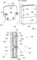
Fig. 1 représente une vue en perspective d'un boîtier électronique selon l'invention, et - la
Fig. 2 montre le boîtier électronique en coupe selon le plan II de laFig. 1 .
- the
Fig. 1 represents a perspective view of an electronic box according to the invention, and - the
Fig. 2 shows the electronic box in section according to plan II of theFig. 1 .
La
- un
socle 102, et - un
boîtier 104.
- a
base 102, and - a
housing 104.
Le socle 102 comprend une plaque 108 destinée à être fixée à un support, tel qu'un mur, et au moins une colonnette principale 110 solidaire de la plaque 108 et s'étendant dans la direction opposée au support. Dans le reste de la description il est fait mention de deux colonnettes principales 110, mais il pourrait y en avoir qu'une seule.The
La plaque 108 est destinée à être fixée sur le support et comporte à cet effet des moyens de fixation 106 adaptés qui sont ici des trous oblongs réalisés dans la plaque 108 et permettant la mise en place de vis de fixation se vissant dans le support. En particulier et avantageusement la plaque 108 ne porte pas de composants électroniques.The
La plaque 108 est relativement légère et peut donc être fixée facilement sur le support par un seul technicien.The
Le socle 102 ne porte aucun composant électronique.The
La
Le boîtier 104 comporte une paroi de fond 202 et une paroi frontale 204 et il porte des composants électroniques qui sont représentés ici par des rectangles 208a-b. Le boîtier 104 peut ainsi constituer une unité autonome.The
La paroi de fond 202 est prévue pour venir en contact avec la plaque 108 et présente pour chaque colonnette principale 110, un alésage traversant 210 permettant le passage de ladite colonnette principale 110.The
La paroi frontale 204 présente également pour chaque colonnette principale 110, un perçage traversant 212 à travers lequel, un moyen principal de solidarisation 214 a accès à ladite colonnette principale 110 pour assurer la solidarisation de ladite colonnette principale 110 et de la paroi frontale 204. Dans le mode de réalisation de l'invention présenté ici, le moyen principal de solidarisation 214 est une vis principale 214 qui est vissée dans la colonnette principale 110 dans un alésage que celle-ci présente à cet effet.The
La mise en place du boîtier électronique 100 consiste après avoir fixé le socle 102 sur le support à emmancher les alésages traversants 210 sur les colonnettes principales 110 puis à mettre en place les moyens principaux de solidarisation 214 correspondants à chaque colonnette principale 110.The establishment of the
L'emmanchement du boîtier 104 sur les colonnettes principales 110 permet de libérer le technicien puisque le boîtier 104 est maintenu par les colonnettes principales 110, le temps de la fixation finale par les moyens principaux de solidarisation 214.The fitting of the
Pour assurer une meilleure stabilisation du boîtier 104 sur les colonnettes principales 110, l'extrémité libre de chaque colonnette principale 110 présente un épaulement 216 sur lequel repose le perçage traversant 212 correspondant.To ensure better stabilization of the
Dans le mode de réalisation de l'invention présenté sur les Figs., la paroi frontale 204 présente une partie fixe 218 et une partie amovible 220.In the embodiment of the invention shown in Figs., The
La partie fixe 218 est solidaire de la paroi de fond 202.The
La partie amovible 220 peut être détachée pour permettre un accès à l'intérieur du boîtier 104 par exemple pour remplacer une batterie 208b.The
Les perçages traversants 212 sont réalisés dans la partie amovible 220.The through
Pour assurer la fixation de la partie amovible 220 lorsque les moyens principaux de solidarisation 214 ne sont pas en place, le boîtier 104 présente au moins une colonnette secondaire 222 solidaire de la paroi de fond 202 et s'étendant dans la direction opposée au support.To secure the
La partie amovible 220 présente également pour chaque colonnette secondaire 222, un autre perçage traversant 224 à travers lequel un moyen secondaire de solidarisation 226 a accès à ladite colonnette secondaire 222 pour assurer la solidarisation de ladite colonnette secondaire 222 et de la partie amovible 220. Dans le mode de réalisation de l'invention présenté ici, le moyen secondaire de solidarisation 226 est une vis secondaire 226 qui est vissée dans la colonnette secondaire 222 dans un alésage que celle-ci présente à cet effet.The
Pour assurer une meilleure stabilisation de la partie amovible 220 sur les colonnettes secondaires 222, l'extrémité libre de chaque colonnette secondaire 222 présente un épaulement 228 sur lequel repose ledit autre perçage traversant 224 correspondant.To ensure better stabilization of the
Bien entendu, la présente invention n'est pas limitée aux exemples et modes de réalisation décrits et représentés, mais elle est susceptible de nombreuses variantes accessibles à l'homme de l'art.Of course, the present invention is not limited to the examples and embodiments described and shown, but it is capable of many variants accessible to those skilled in the art.
Claims (3)
- Electronic box (100) comprising:- a base (102) having a plate (108) intended to be fixed to a support and at least a main column (110) fixed to the plate (108), and- a case (104) comprising a bottom wall (202) and a front wall (204) and carrying electronic components (208),
the bottom wall (202) is intended to come in contact with the plate (108) and has for the or each main column (110), a through bore (210) allowing the passage of said main column (110), and
the front wall (204) has for the or each main column (110), a main through hole (212) through which, a main mean of fixing (214) has access to said main column (110) to ensure the fixation of said main column (110) and of the front wall (204),
the electronic box (100) beingcharacterized in that the front wall (204) has a fixed part (218) fixed to the bottom wall (202), and a removable part (220) in which the through holes (212) are realized,in that the electronic box (100) comprises at least one secondary column (222) fixed to the bottom wall (202), andin that the removable part (220) has for each secondary column (222), another through hole (224) through which a secondary mean of fixing (226) has access to said secondary column (222) to ensure the fixation of said secondary column (222) and the removable part (220). - Electronic box (100) according to claim 1,characterized in that the free end of the or each main column (110) has a shoulder (216) on which the corresponding through hole (212) lies.
- Electronic box (100) according to any one of the claims 1 or 2,characterized in that the free end of each secondary column (222) has a shoulder (228) on which corresponding said other through hole (224) lies.
Applications Claiming Priority (1)
| Application Number | Priority Date | Filing Date | Title |
|---|---|---|---|
| FR1457274AFR3024320B1 (en) | 2014-07-28 | 2014-07-28 | ELECTRONIC HOUSING HAVING A BASE |
Publications (2)
| Publication Number | Publication Date |
|---|---|
| EP2981159A1 EP2981159A1 (en) | 2016-02-03 |
| EP2981159B1true EP2981159B1 (en) | 2019-04-03 |
Family
ID=51932390
Family Applications (1)
| Application Number | Title | Priority Date | Filing Date |
|---|---|---|---|
| EP15178495.6AActiveEP2981159B1 (en) | 2014-07-28 | 2015-07-27 | Electronic box having a base |
Country Status (3)
| Country | Link |
|---|---|
| EP (1) | EP2981159B1 (en) |
| ES (1) | ES2732847T3 (en) |
| FR (1) | FR3024320B1 (en) |
Citations (1)
| Publication number | Priority date | Publication date | Assignee | Title |
|---|---|---|---|---|
| US3734342A (en)* | 1971-07-09 | 1973-05-22 | Adams Russel Co Inc | Box enclosure for electrical circuits |
Family Cites Families (1)
| Publication number | Priority date | Publication date | Assignee | Title |
|---|---|---|---|---|
| DE1991579U (en)* | 1968-08-14 | Siemens Aktiengesellschaft 1000 Berlin und 8000 München JAntennenverstarkeranordnung bei der ie Gehäuse über ein verlangerbares Halteorgan an einer Unterlage befestigt sind 20 4 66 |
- 2014
- 2014-07-28FRFR1457274Apatent/FR3024320B1/enactiveActive
- 2015
- 2015-07-27ESES15178495Tpatent/ES2732847T3/enactiveActive
- 2015-07-27EPEP15178495.6Apatent/EP2981159B1/enactiveActive
Patent Citations (1)
| Publication number | Priority date | Publication date | Assignee | Title |
|---|---|---|---|---|
| US3734342A (en)* | 1971-07-09 | 1973-05-22 | Adams Russel Co Inc | Box enclosure for electrical circuits |
Also Published As
| Publication number | Publication date |
|---|---|
| FR3024320A1 (en) | 2016-01-29 |
| FR3024320B1 (en) | 2018-07-06 |
| EP2981159A1 (en) | 2016-02-03 |
| ES2732847T3 (en) | 2019-11-26 |
Similar Documents
| Publication | Publication Date | Title |
|---|---|---|
| EP3969329B1 (en) | Arrangement for mounting an optical system on a body element of a vehicle | |
| EP3149433A1 (en) | Arrangement for mounting a functional component such as a camera on a motor vehicle bodywork element | |
| EP1087075A1 (en) | Permanent anchoring device | |
| EP2981159B1 (en) | Electronic box having a base | |
| EP2039853B1 (en) | Assembly comprising a fence post and a case | |
| FR2797357A3 (en) | Electrical wall or ceiling connection box for thin wall-board mounting, has box concealed behind board with access for completion only from the front side | |
| EP0911932B1 (en) | Mounting adapter for non square shaped electrical apparatus | |
| FR2918216A1 (en) | Rapid and securized electrical connection ensuring device for e.g. lighting equipment, has support with orifices, where opening of orifices is carried out at distance from connectors under magnetization effect to maintain connectors | |
| EP3309916B1 (en) | Electrical equipment housing, electrical apparatus for such housing and electrical equipment comprising such housing and electrical appliance | |
| EP0587521A1 (en) | Display device for poster support | |
| FR2806792A3 (en) | TIGHTENING DEVICE FOR LEVEL | |
| EP2993479A2 (en) | Assembly of support and/or fixing for at least one electrical measurement device | |
| EP1343238B1 (en) | Box for electrical apparatus comprising flexible fasteners | |
| EP2784761B1 (en) | Electronic cabinet provided with a removal detection member | |
| EP1876681B1 (en) | Housing with rails for mounting an electrical device | |
| FR2847733A1 (en) | Switchgear, has projecting part on fixing plate of embedded part and mounting clamp equipped with blocking unit in assembled position forming theft-prevention device | |
| EP3788661B1 (en) | Device for attaching a 12v battery to a battery support, and motor vehicle comprising such a device | |
| FR2927198A1 (en) | Electrical connecting device i.e. electrical plug-in connector for e.g. electric wires, has angular orientation verification unit verifying angular orientation of device with respect to horizontal when base is pre-assembled in wall | |
| FR3017020A1 (en) | FIXING STAND FOR SURVEILLANCE CAMERA AND COMPLEMENTARY FIXING MEMBER. | |
| FR2710786A1 (en) | Simplified and quick-fitting electrical plug | |
| FR3037635A1 (en) | SAFETY LIGHTING DEVICE | |
| FR3039012B1 (en) | APPARATUS FOR ADAPTING AN ELECTRICAL DEVICE HOUSING TO A WALL MOLDING AND AN APPARATUS HOUSING PROVIDED WITH SUCH A DEVICE | |
| FR2734423A1 (en) | BUILT-IN BOX FOR ELECTRICAL EQUIPMENT | |
| EP3795422A1 (en) | Assembly comprising a lighting device and a trim element of a motor vehicle | |
| FR2819949A1 (en) | ARRANGEMENT OF AN ELECTRICAL CONNECTION DEVICE OF A BUILT-IN LUMINAIRE |
Legal Events
| Date | Code | Title | Description |
|---|---|---|---|
| PUAI | Public reference made under article 153(3) epc to a published international application that has entered the european phase | Free format text:ORIGINAL CODE: 0009012 | |
| AK | Designated contracting states | Kind code of ref document:A1 Designated state(s):AL AT BE BG CH CY CZ DE DK EE ES FI FR GB GR HR HU IE IS IT LI LT LU LV MC MK MT NL NO PL PT RO RS SE SI SK SM TR | |
| AX | Request for extension of the european patent | Extension state:BA ME | |
| 17P | Request for examination filed | Effective date:20160427 | |
| RBV | Designated contracting states (corrected) | Designated state(s):AL AT BE BG CH CY CZ DE DK EE ES FI FR GB GR HR HU IE IS IT LI LT LU LV MC MK MT NL NO PL PT RO RS SE SI SK SM TR | |
| RIC1 | Information provided on ipc code assigned before grant | Ipc:H05K 5/02 20060101AFI20160526BHEP | |
| 17Q | First examination report despatched | Effective date:20160622 | |
| GRAP | Despatch of communication of intention to grant a patent | Free format text:ORIGINAL CODE: EPIDOSNIGR1 | |
| STAA | Information on the status of an ep patent application or granted ep patent | Free format text:STATUS: GRANT OF PATENT IS INTENDED | |
| INTG | Intention to grant announced | Effective date:20181102 | |
| GRAS | Grant fee paid | Free format text:ORIGINAL CODE: EPIDOSNIGR3 | |
| GRAA | (expected) grant | Free format text:ORIGINAL CODE: 0009210 | |
| STAA | Information on the status of an ep patent application or granted ep patent | Free format text:STATUS: THE PATENT HAS BEEN GRANTED | |
| AK | Designated contracting states | Kind code of ref document:B1 Designated state(s):AL AT BE BG CH CY CZ DE DK EE ES FI FR GB GR HR HU IE IS IT LI LT LU LV MC MK MT NL NO PL PT RO RS SE SI SK SM TR | |
| REG | Reference to a national code | Ref country code:GB Ref legal event code:FG4D Free format text:NOT ENGLISH | |
| REG | Reference to a national code | Ref country code:CH Ref legal event code:EP Ref country code:AT Ref legal event code:REF Ref document number:1117389 Country of ref document:AT Kind code of ref document:T Effective date:20190415 | |
| REG | Reference to a national code | Ref country code:DE Ref legal event code:R096 Ref document number:602015027459 Country of ref document:DE | |
| REG | Reference to a national code | Ref country code:IE Ref legal event code:FG4D Free format text:LANGUAGE OF EP DOCUMENT: FRENCH | |
| REG | Reference to a national code | Ref country code:NL Ref legal event code:MP Effective date:20190403 | |
| REG | Reference to a national code | Ref country code:LT Ref legal event code:MG4D | |
| REG | Reference to a national code | Ref country code:AT Ref legal event code:MK05 Ref document number:1117389 Country of ref document:AT Kind code of ref document:T Effective date:20190403 | |
| PG25 | Lapsed in a contracting state [announced via postgrant information from national office to epo] | Ref country code:NL Free format text:LAPSE BECAUSE OF FAILURE TO SUBMIT A TRANSLATION OF THE DESCRIPTION OR TO PAY THE FEE WITHIN THE PRESCRIBED TIME-LIMIT Effective date:20190403 | |
| PG25 | Lapsed in a contracting state [announced via postgrant information from national office to epo] | Ref country code:AL Free format text:LAPSE BECAUSE OF FAILURE TO SUBMIT A TRANSLATION OF THE DESCRIPTION OR TO PAY THE FEE WITHIN THE PRESCRIBED TIME-LIMIT Effective date:20190403 Ref country code:LT Free format text:LAPSE BECAUSE OF FAILURE TO SUBMIT A TRANSLATION OF THE DESCRIPTION OR TO PAY THE FEE WITHIN THE PRESCRIBED TIME-LIMIT Effective date:20190403 Ref country code:CZ Free format text:LAPSE BECAUSE OF FAILURE TO SUBMIT A TRANSLATION OF THE DESCRIPTION OR TO PAY THE FEE WITHIN THE PRESCRIBED TIME-LIMIT Effective date:20190403 Ref country code:NO Free format text:LAPSE BECAUSE OF FAILURE TO SUBMIT A TRANSLATION OF THE DESCRIPTION OR TO PAY THE FEE WITHIN THE PRESCRIBED TIME-LIMIT Effective date:20190703 Ref country code:HR Free format text:LAPSE BECAUSE OF FAILURE TO SUBMIT A TRANSLATION OF THE DESCRIPTION OR TO PAY THE FEE WITHIN THE PRESCRIBED TIME-LIMIT Effective date:20190403 Ref country code:SE Free format text:LAPSE BECAUSE OF FAILURE TO SUBMIT A TRANSLATION OF THE DESCRIPTION OR TO PAY THE FEE WITHIN THE PRESCRIBED TIME-LIMIT Effective date:20190403 Ref country code:FI Free format text:LAPSE BECAUSE OF FAILURE TO SUBMIT A TRANSLATION OF THE DESCRIPTION OR TO PAY THE FEE WITHIN THE PRESCRIBED TIME-LIMIT Effective date:20190403 Ref country code:PT Free format text:LAPSE BECAUSE OF FAILURE TO SUBMIT A TRANSLATION OF THE DESCRIPTION OR TO PAY THE FEE WITHIN THE PRESCRIBED TIME-LIMIT Effective date:20190803 | |
| REG | Reference to a national code | Ref country code:ES Ref legal event code:FG2A Ref document number:2732847 Country of ref document:ES Kind code of ref document:T3 Effective date:20191126 | |
| PG25 | Lapsed in a contracting state [announced via postgrant information from national office to epo] | Ref country code:RS Free format text:LAPSE BECAUSE OF FAILURE TO SUBMIT A TRANSLATION OF THE DESCRIPTION OR TO PAY THE FEE WITHIN THE PRESCRIBED TIME-LIMIT Effective date:20190403 Ref country code:LV Free format text:LAPSE BECAUSE OF FAILURE TO SUBMIT A TRANSLATION OF THE DESCRIPTION OR TO PAY THE FEE WITHIN THE PRESCRIBED TIME-LIMIT Effective date:20190403 Ref country code:GR Free format text:LAPSE BECAUSE OF FAILURE TO SUBMIT A TRANSLATION OF THE DESCRIPTION OR TO PAY THE FEE WITHIN THE PRESCRIBED TIME-LIMIT Effective date:20190704 Ref country code:PL Free format text:LAPSE BECAUSE OF FAILURE TO SUBMIT A TRANSLATION OF THE DESCRIPTION OR TO PAY THE FEE WITHIN THE PRESCRIBED TIME-LIMIT Effective date:20190403 Ref country code:BG Free format text:LAPSE BECAUSE OF FAILURE TO SUBMIT A TRANSLATION OF THE DESCRIPTION OR TO PAY THE FEE WITHIN THE PRESCRIBED TIME-LIMIT Effective date:20190703 | |
| PG25 | Lapsed in a contracting state [announced via postgrant information from national office to epo] | Ref country code:IS Free format text:LAPSE BECAUSE OF FAILURE TO SUBMIT A TRANSLATION OF THE DESCRIPTION OR TO PAY THE FEE WITHIN THE PRESCRIBED TIME-LIMIT Effective date:20190803 Ref country code:AT Free format text:LAPSE BECAUSE OF FAILURE TO SUBMIT A TRANSLATION OF THE DESCRIPTION OR TO PAY THE FEE WITHIN THE PRESCRIBED TIME-LIMIT Effective date:20190403 | |
| REG | Reference to a national code | Ref country code:DE Ref legal event code:R097 Ref document number:602015027459 Country of ref document:DE | |
| PG25 | Lapsed in a contracting state [announced via postgrant information from national office to epo] | Ref country code:RO Free format text:LAPSE BECAUSE OF FAILURE TO SUBMIT A TRANSLATION OF THE DESCRIPTION OR TO PAY THE FEE WITHIN THE PRESCRIBED TIME-LIMIT Effective date:20190403 Ref country code:SK Free format text:LAPSE BECAUSE OF FAILURE TO SUBMIT A TRANSLATION OF THE DESCRIPTION OR TO PAY THE FEE WITHIN THE PRESCRIBED TIME-LIMIT Effective date:20190403 Ref country code:EE Free format text:LAPSE BECAUSE OF FAILURE TO SUBMIT A TRANSLATION OF THE DESCRIPTION OR TO PAY THE FEE WITHIN THE PRESCRIBED TIME-LIMIT Effective date:20190403 Ref country code:DK Free format text:LAPSE BECAUSE OF FAILURE TO SUBMIT A TRANSLATION OF THE DESCRIPTION OR TO PAY THE FEE WITHIN THE PRESCRIBED TIME-LIMIT Effective date:20190403 | |
| PLBE | No opposition filed within time limit | Free format text:ORIGINAL CODE: 0009261 | |
| STAA | Information on the status of an ep patent application or granted ep patent | Free format text:STATUS: NO OPPOSITION FILED WITHIN TIME LIMIT | |
| PG25 | Lapsed in a contracting state [announced via postgrant information from national office to epo] | Ref country code:MC Free format text:LAPSE BECAUSE OF FAILURE TO SUBMIT A TRANSLATION OF THE DESCRIPTION OR TO PAY THE FEE WITHIN THE PRESCRIBED TIME-LIMIT Effective date:20190403 Ref country code:SM Free format text:LAPSE BECAUSE OF FAILURE TO SUBMIT A TRANSLATION OF THE DESCRIPTION OR TO PAY THE FEE WITHIN THE PRESCRIBED TIME-LIMIT Effective date:20190403 | |
| REG | Reference to a national code | Ref country code:CH Ref legal event code:PL | |
| 26N | No opposition filed | Effective date:20200106 | |
| PG25 | Lapsed in a contracting state [announced via postgrant information from national office to epo] | Ref country code:TR Free format text:LAPSE BECAUSE OF FAILURE TO SUBMIT A TRANSLATION OF THE DESCRIPTION OR TO PAY THE FEE WITHIN THE PRESCRIBED TIME-LIMIT Effective date:20190403 | |
| REG | Reference to a national code | Ref country code:BE Ref legal event code:MM Effective date:20190731 | |
| PG25 | Lapsed in a contracting state [announced via postgrant information from national office to epo] | Ref country code:LI Free format text:LAPSE BECAUSE OF NON-PAYMENT OF DUE FEES Effective date:20190731 Ref country code:BE Free format text:LAPSE BECAUSE OF NON-PAYMENT OF DUE FEES Effective date:20190731 Ref country code:CH Free format text:LAPSE BECAUSE OF NON-PAYMENT OF DUE FEES Effective date:20190731 Ref country code:SI Free format text:LAPSE BECAUSE OF FAILURE TO SUBMIT A TRANSLATION OF THE DESCRIPTION OR TO PAY THE FEE WITHIN THE PRESCRIBED TIME-LIMIT Effective date:20190403 Ref country code:LU Free format text:LAPSE BECAUSE OF NON-PAYMENT OF DUE FEES Effective date:20190727 | |
| PG25 | Lapsed in a contracting state [announced via postgrant information from national office to epo] | Ref country code:IE Free format text:LAPSE BECAUSE OF NON-PAYMENT OF DUE FEES Effective date:20190727 | |
| PG25 | Lapsed in a contracting state [announced via postgrant information from national office to epo] | Ref country code:CY Free format text:LAPSE BECAUSE OF FAILURE TO SUBMIT A TRANSLATION OF THE DESCRIPTION OR TO PAY THE FEE WITHIN THE PRESCRIBED TIME-LIMIT Effective date:20190403 | |
| PG25 | Lapsed in a contracting state [announced via postgrant information from national office to epo] | Ref country code:HU Free format text:LAPSE BECAUSE OF FAILURE TO SUBMIT A TRANSLATION OF THE DESCRIPTION OR TO PAY THE FEE WITHIN THE PRESCRIBED TIME-LIMIT; INVALID AB INITIO Effective date:20150727 Ref country code:MT Free format text:LAPSE BECAUSE OF FAILURE TO SUBMIT A TRANSLATION OF THE DESCRIPTION OR TO PAY THE FEE WITHIN THE PRESCRIBED TIME-LIMIT Effective date:20190403 | |
| PG25 | Lapsed in a contracting state [announced via postgrant information from national office to epo] | Ref country code:MK Free format text:LAPSE BECAUSE OF FAILURE TO SUBMIT A TRANSLATION OF THE DESCRIPTION OR TO PAY THE FEE WITHIN THE PRESCRIBED TIME-LIMIT Effective date:20190403 | |
| PGFP | Annual fee paid to national office [announced via postgrant information from national office to epo] | Ref country code:GB Payment date:20220721 Year of fee payment:8 | |
| PGFP | Annual fee paid to national office [announced via postgrant information from national office to epo] | Ref country code:ES Payment date:20230926 Year of fee payment:9 | |
| GBPC | Gb: european patent ceased through non-payment of renewal fee | Effective date:20230727 | |
| PG25 | Lapsed in a contracting state [announced via postgrant information from national office to epo] | Ref country code:GB Free format text:LAPSE BECAUSE OF NON-PAYMENT OF DUE FEES Effective date:20230727 | |
| PGFP | Annual fee paid to national office [announced via postgrant information from national office to epo] | Ref country code:DE Payment date:20240719 Year of fee payment:10 | |
| PGFP | Annual fee paid to national office [announced via postgrant information from national office to epo] | Ref country code:FR Payment date:20240729 Year of fee payment:10 | |
| PGFP | Annual fee paid to national office [announced via postgrant information from national office to epo] | Ref country code:IT Payment date:20240725 Year of fee payment:10 | |
| REG | Reference to a national code | Ref country code:ES Ref legal event code:FD2A Effective date:20250905 | |
| PG25 | Lapsed in a contracting state [announced via postgrant information from national office to epo] | Ref country code:ES Free format text:LAPSE BECAUSE OF NON-PAYMENT OF DUE FEES Effective date:20240728 |