EP2980393B1 - Gas turbine engine - Google Patents
Gas turbine engineDownload PDFInfo
- Publication number
- EP2980393B1 EP2980393B1EP15179131.6AEP15179131AEP2980393B1EP 2980393 B1EP2980393 B1EP 2980393B1EP 15179131 AEP15179131 AEP 15179131AEP 2980393 B1EP2980393 B1EP 2980393B1
- Authority
- EP
- European Patent Office
- Prior art keywords
- engine
- flow
- gas turbine
- primary
- guide ring
- Prior art date
- Legal status (The legal status is an assumption and is not a legal conclusion. Google has not performed a legal analysis and makes no representation as to the accuracy of the status listed.)
- Active
Links
Images


Classifications
- F—MECHANICAL ENGINEERING; LIGHTING; HEATING; WEAPONS; BLASTING
- F02—COMBUSTION ENGINES; HOT-GAS OR COMBUSTION-PRODUCT ENGINE PLANTS
- F02K—JET-PROPULSION PLANTS
- F02K1/00—Plants characterised by the form or arrangement of the jet pipe or nozzle; Jet pipes or nozzles peculiar thereto
- F02K1/38—Introducing air inside the jet
- F02K1/386—Introducing air inside the jet mixing devices in the jet pipe, e.g. for mixing primary and secondary flow
- F—MECHANICAL ENGINEERING; LIGHTING; HEATING; WEAPONS; BLASTING
- F02—COMBUSTION ENGINES; HOT-GAS OR COMBUSTION-PRODUCT ENGINE PLANTS
- F02C—GAS-TURBINE PLANTS; AIR INTAKES FOR JET-PROPULSION PLANTS; CONTROLLING FUEL SUPPLY IN AIR-BREATHING JET-PROPULSION PLANTS
- F02C3/00—Gas-turbine plants characterised by the use of combustion products as the working fluid
- F02C3/04—Gas-turbine plants characterised by the use of combustion products as the working fluid having a turbine driving a compressor
- F02C3/10—Gas-turbine plants characterised by the use of combustion products as the working fluid having a turbine driving a compressor with another turbine driving an output shaft but not driving the compressor
- F—MECHANICAL ENGINEERING; LIGHTING; HEATING; WEAPONS; BLASTING
- F02—COMBUSTION ENGINES; HOT-GAS OR COMBUSTION-PRODUCT ENGINE PLANTS
- F02K—JET-PROPULSION PLANTS
- F02K1/00—Plants characterised by the form or arrangement of the jet pipe or nozzle; Jet pipes or nozzles peculiar thereto
- F02K1/28—Plants characterised by the form or arrangement of the jet pipe or nozzle; Jet pipes or nozzles peculiar thereto using fluid jets to influence the jet flow
- F02K1/34—Plants characterised by the form or arrangement of the jet pipe or nozzle; Jet pipes or nozzles peculiar thereto using fluid jets to influence the jet flow for attenuating noise
- F—MECHANICAL ENGINEERING; LIGHTING; HEATING; WEAPONS; BLASTING
- F02—COMBUSTION ENGINES; HOT-GAS OR COMBUSTION-PRODUCT ENGINE PLANTS
- F02K—JET-PROPULSION PLANTS
- F02K1/00—Plants characterised by the form or arrangement of the jet pipe or nozzle; Jet pipes or nozzles peculiar thereto
- F02K1/46—Nozzles having means for adding air to the jet or for augmenting the mixing region between the jet and the ambient air, e.g. for silencing
- F02K1/48—Corrugated nozzles
- F—MECHANICAL ENGINEERING; LIGHTING; HEATING; WEAPONS; BLASTING
- F05—INDEXING SCHEMES RELATING TO ENGINES OR PUMPS IN VARIOUS SUBCLASSES OF CLASSES F01-F04
- F05D—INDEXING SCHEME FOR ASPECTS RELATING TO NON-POSITIVE-DISPLACEMENT MACHINES OR ENGINES, GAS-TURBINES OR JET-PROPULSION PLANTS
- F05D2220/00—Application
- F05D2220/30—Application in turbines
- F05D2220/32—Application in turbines in gas turbines
- F05D2220/324—Application in turbines in gas turbines to drive unshrouded, low solidity propeller
- F—MECHANICAL ENGINEERING; LIGHTING; HEATING; WEAPONS; BLASTING
- F05—INDEXING SCHEMES RELATING TO ENGINES OR PUMPS IN VARIOUS SUBCLASSES OF CLASSES F01-F04
- F05D—INDEXING SCHEME FOR ASPECTS RELATING TO NON-POSITIVE-DISPLACEMENT MACHINES OR ENGINES, GAS-TURBINES OR JET-PROPULSION PLANTS
- F05D2250/00—Geometry
- F05D2250/20—Three-dimensional
- F05D2250/23—Three-dimensional prismatic
- F05D2250/232—Three-dimensional prismatic conical
- F—MECHANICAL ENGINEERING; LIGHTING; HEATING; WEAPONS; BLASTING
- F05—INDEXING SCHEMES RELATING TO ENGINES OR PUMPS IN VARIOUS SUBCLASSES OF CLASSES F01-F04
- F05D—INDEXING SCHEME FOR ASPECTS RELATING TO NON-POSITIVE-DISPLACEMENT MACHINES OR ENGINES, GAS-TURBINES OR JET-PROPULSION PLANTS
- F05D2250/00—Geometry
- F05D2250/60—Structure; Surface texture
- F05D2250/61—Structure; Surface texture corrugated
- F—MECHANICAL ENGINEERING; LIGHTING; HEATING; WEAPONS; BLASTING
- F05—INDEXING SCHEMES RELATING TO ENGINES OR PUMPS IN VARIOUS SUBCLASSES OF CLASSES F01-F04
- F05D—INDEXING SCHEME FOR ASPECTS RELATING TO NON-POSITIVE-DISPLACEMENT MACHINES OR ENGINES, GAS-TURBINES OR JET-PROPULSION PLANTS
- F05D2260/00—Function
- F05D2260/60—Fluid transfer
- F05D2260/601—Fluid transfer using an ejector or a jet pump
Definitions
- the applicationrelates generally to aircraft gas turbine engines and, more particularly, to aft section of the engine including an ejector.
- Turbofan enginesIn gas turbine engines, hot high velocity air exits from the turbine through the core gas path.
- the exhaust gasesmay be constrained by an exhaust case section in the form of a corrugated annular case extension having lobes.
- Turbofan enginesgenerally use exhaust mixers in order to increase the mixing of the high and low velocity exhaust gas flows.
- Turbo-shaft and turbo-prop enginesmay be provided with similar devices sometimes referred to as ejectors.
- Exhaust mixers/ejectorsmay experience thermal variation and/or radial deflection due to exposure to the high and low velocity flows.
- exhaust ejector/mixersmay be prone to vibrations, which have negative consequences for the surrounding hardware. As such, it is generally desirable to increase the stiffness or rigidity of the exhaust case.
- Various configurations of exhaust ejector/mixershave been proposed to date in order to try to increase the stiffness or reduce deflection thereof.
- the aerodynamic performance of ejectorsis often limited by the ability of the primary flow to entrain the secondary cooling flow. Increasing the ejector capacity of pumping secondary mass flow would also be desirable from an aerodynamic point of view.
- US 3, 726, 091discloses a prior art gas turbine engine according to the preamble of claim 1.
- US 2010/0199626 A1discloses a further prior art gas turbine engine.
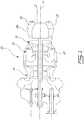
- Fig. 1illustrates a turbo-shaft gas turbine engine 10 of a type preferably provided for use in subsonic flight, generally comprising in serial flow communication a compressor section 14 for pressurizing the air, a combustor 16 in which the compressed air is mixed with fuel and ignited for generating an annular stream of hot combustion gases, and a turbine section 18 for extracting energy from the combustion gases.
- the gas turbine engine 10includes a core engine casing 20 which encloses the turbo machinery of the engine.
- the main air flowpasses through the core of the engine via a main gas path 26, which is circumscribed by the core engine casing 20 and allows the flow to circulate through the multistage compressor 14, combustor 16 and turbine section 18 as described above.
- an engine center body 22is centered about a longitudinal axis X of the engine 10, the engine center body 22 being connected to an aft end of the turbine section 18.
- the engine center bodycan take the form of an exhaust cone depending on the application.
- the engine center body 22has an outer surface, which defines an inner wall of the main gas path 26 so that the combustion gases flow therearound.
- An ejector/mixer 30forms the outer wall of the aft end of the main gas path 26.
- the ejector/mixer 30includes a primary nozzle having an annular wall 34 with a radial fastening ring or flange 32 upstream thereof.
- the fastening ring 32is adapted to be mechanically fastened to the aft portion 20a ( Fig. 1 ) of the casing 20.
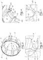
- the annular wall 34 of the primary nozzleincludes and defines a plurality of circumferentially distributed radially inner lobes 36 extending axially rearwardly from a front frusto-conical portion of the annular wall 34 to a downstream edge 37, i.e. a trailing edge thereof.
- the lobes 36include side, radially-extending, walls 38 with a bight forming an arcuate trough 40.
- the trough 40presents a convex surface 41 on the radially inner or central side of the annular wall 34.
- An annular support memberincludes an annular blade 42 extending concentrically about the longitudinal axis X of the engine 10.
- the blade 42comprises an annular longitudinal, flat bar.
- the blade 42is interrupted only at form-fitting joint areas 44.
- the joint areas 44are located on the blade 42 to correspond with the convex surfaces 41 of the lobes 36.
- the joint areas 44are curved so that it complements the convex surface 41, as shown in Fig. 3 .
- the curved joint area 44is concave relative to the convex surface 41 of the lobe 36.
- the blade 42is spaced radially outwardly and independent from the engine center body 22 and floats with respect thereto.
- the blade 42in one embodiment is a thin sheet metal strip capable of being welded to the sheet metal forming the annular wall 34. In the embodiment shown in Figs. 2 and 3 , the thin sheet metal strip is formed into a continuous ring.
- the ejector/mixer 30is solely connected to the engine 10 at the aft end 20a of the core engine casing 20, and so, the ejector/mixer 30 is effectively cantilevered from the core engine casing 20.
- This cantilevered configurationallows the lobes 36 of the exhaust ejector/mixer 30 to vibrate at one or more modes in the engine operating frequency range, while remaining relatively stiff.
- the thermal variations in the exhaust mixer 30 due to the high and low velocity flows through the main gas path 26may cause axial and radial displacements in the ejector/mixer 30, which can accordingly be absorbed by the exhaust ejector/mixer 30.
- the downstream end 37 of the ejector/mixer 30, which would otherwise be prone to deflection,is reinforced by the blade 42 which serves to increase the rigidity of the exhaust ejector/mixer 30 and thus inhibit movement at the downstream end 37 thereof.
- the blade 42which serves to increase the rigidity of the exhaust ejector/mixer 30 and thus inhibit movement at the downstream end 37 thereof.
- any movement of the ejector/mixer 30is reduced, as are the vibrations thereof.
- the blade 42is able to accommodate any axial or radial displacements due to such thermal variations.
- the ejector/mixer 30provides enhanced rigidity and may accommodate thermal variations, vibrations and other displacements, as required.
- the bladeis made up of blade segments 142a, 142b... 142n.
- Each segmenthas a length corresponding to the distance between the center lines of two adjacent lobes 36.
- Each end of the segmentterminates in a partially formed concave curve to complement part of the convex surface 41 of the lobe 36.
- corresponding ends of segments 142a and 142bmake-up the form fitting joint area 144.
- the blade 42, 142may be located at different axial positions along the convex surfaces 41 of the lobe 36.
- Figure 3illustrates a blade 42 being spaced upstream from the trailing edge 37, of the lobe 36.
- the blade 142is located at or slightly downstream from the trailing edge 37, of the lobe 36.
- the blade 42, 142may be fixed to the convex surfaces 41 of the lobes 36 at joint areas 44, 144 using a combination of resistance, fusion or ball tack welding with a brazing application, or other types of suitable bonding that are well known in the art.
- the support memberis often, according to the prior art, subject to thermal stresses caused by the entrained cool air and of the hot air exiting the turbine 18.
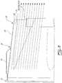
- Figures 6 and 7show the gases flow in the ejector/mixer 30.
- the blade 42, 142is disposed directly in the main gas path 26 and is shaped to be laminar with the flow of the hot gases, as can be seen in both figures 6 and 7 .
- the blade 42is essentially exposed only to the hot gases flowing in the main gas path 26. This reduces the thermal gradient in the blade 42, 142.
- the above described embodimentsprovide an improved exhaust ejector/mixer for a gas turbine engine where the thermal stresses on the support member are reduced for improved longevity.
- the ejector/mixer and the support membercould be made by additive manufacturing processes, such as direct metal laser sintering. Therefore, the ejector/mixer and the support member could be made monolithically.
- the exhaust sectionis referred to as an ejector.
- the support membermay also act as a flow guide ring to guide the primary flow when leaving the primary nozzle and, thus, enhance the ejector aerodynamic performance.
- Fig. 8illustrates an ejector 200 comprising a primary nozzle 201, a secondary nozzle 203 concentrically mounted about the primary nozzle 201 and a flow guide ring 205 concentrically mounted inside the primary nozzle 201.
- the primary nozzle 201has an annular wall 234 forming part of the outer boundary of an exhaust portion of the main or primary flow passage of the engine.
- the annular wall 234has a downstream end formed with circumferentially distributed radially inner lobes 236.
- the flow guide ring 205is attached to the radially inner surface of the lobe valleys as described herein above.
- the secondary nozzle 203has an annular bell-shaped wall extending from the engine compartment wall case (not shown) about the primary nozzle 201. As best shown in Fig. 9 , the primary nozzle 201 and the secondary nozzle 203 define a secondary flow path 207 therebetween for guiding a secondary flow of cooling air.
- the secondary nozzle 203extends axially downstream of the primary nozzle 201 and defines a mixing zone 209 at the exit of the primary nozzle 201 where the high velocity primary flow mixes with the secondary flow.
- primary nozzle 201 of the ejector 200extends axially downstream of the engine center body 22 (i.e. the inner boundary of the primary flow passage ends upstream of its outer boundary). As a result, the primary flow tends to diffuse towards the engine centerline downstream of the end of the center body 22.
- the addition of a properly designed flow guide ring 205can prevent the annular high momentum primary flow from diffusing and guide the flow through the annular zone between the flow guide ring 205 and the primary nozzle 201 where the primary and secondary flows mix. Due to this fact, the capacity of pumping secondary mass flow may be improved.
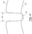
- the flow guide ring 205has a cone shape with a proper angle (P1) with respect to engine axis (see Fig. 9 ). This is to ensure that the primary flow is well guided without separation when leaving the primary nozzle and entering the mixing zone.
- the ring cone draft angle (P1)may be in the range of about 0° to about 10° and is preferably about 5°.
- the flow guide ring 205could be cylindrical or airfoil-shaped as well.
- the flow guide ring 205has an aerodynamic surface extending axially from a leading edge 205a to a trailing edge 205b.
- the leading edge 205a and the trailing edge 205bare respectively disposed upstream and downstream of the primary nozzle exit to properly guide the primary flow leaving the primary nozzle 201 into the mixing zone 209.
- the flow guide ring 205projects out of the primary nozzle 201 or extends downstream from the exit of the primary nozzle 201 by a distance (P5) for extended flow guidance in the mixing zone and avoidance of flow separation across the ring 205.
- the distance (P5)is in the range of about 0 to about 1 inch (25.4 mm).
- the length (P2) of the guide ring 205 and its axial installation position (P3) relative to the end of the center body 22may also influence the aerodynamic performance of the ejector 200. It is understood that (P2) and (P3) can be optimized depending on different applications. According to a particular application, the ring length (P2) is in the range of about 0.5 to about 2 inches (12.7 to 50.8 mm) and the ring 205 is installed axially at the primary nozzle exit.
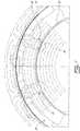
- the radial installation position of the guide ringmay vary depending on various conditions. According to the illustrated embodiment, the ring 205 is installed at the lobe valley. It is also understood that the lobe design and the number of lobes 236 may vary depending on the applications. According to the illustrated embodiment, the lobes 236 have a draft angle (P6) of about 0° to about 5° ( Figure 10 ). Such a small draft angle can help prevent reverse back secondary flow.
- the number of lobesmay vary depending on the size of the engine. For the exemplified application given above, the number of lobes may range between 8 and 10.
Landscapes
- Engineering & Computer Science (AREA)
- Chemical & Material Sciences (AREA)
- Combustion & Propulsion (AREA)
- Mechanical Engineering (AREA)
- General Engineering & Computer Science (AREA)
- Jet Pumps And Other Pumps (AREA)
Description
- The application relates generally to aircraft gas turbine engines and, more particularly, to aft section of the engine including an ejector.
- In gas turbine engines, hot high velocity air exits from the turbine through the core gas path. The exhaust gases may be constrained by an exhaust case section in the form of a corrugated annular case extension having lobes. Turbofan engines generally use exhaust mixers in order to increase the mixing of the high and low velocity exhaust gas flows. Turbo-shaft and turbo-prop engines may be provided with similar devices sometimes referred to as ejectors. Exhaust mixers/ejectors may experience thermal variation and/or radial deflection due to exposure to the high and low velocity flows. In addition, exhaust ejector/mixers may be prone to vibrations, which have negative consequences for the surrounding hardware. As such, it is generally desirable to increase the stiffness or rigidity of the exhaust case. Various configurations of exhaust ejector/mixers have been proposed to date in order to try to increase the stiffness or reduce deflection thereof.
- Also, the aerodynamic performance of ejectors is often limited by the ability of the primary flow to entrain the secondary cooling flow. Increasing the ejector capacity of pumping secondary mass flow would also be desirable from an aerodynamic point of view.
US 3, 726, 091 discloses a prior art gas turbine engine according to the preamble of claim 1.US 2010/0199626 A1 discloses a further prior art gas turbine engine.- According to the present invention there is provided a gas turbine engine as set forth in claim 1.
- Reference is now made to the accompanying figures in which:
Fig. 1 is a schematic cross-sectional view of a turbo-shaft gas turbine engine;Fig. 2 is a rear isometric view of an exhaust ejector/mixer, having a support member connected to the ejector/mixer lobes thereof, in accordance with one embodiment of the present disclosure;Fig. 3 is an enlarged fragmentary, isometric view of a lobe and support member according toFig.2 ;Fig. 4 is a fragmentary rear isometric view an ejector/mixer, having a support member connected to the lobes thereof, in accordance with another embodiment;Fig. 5 is an enlarged fragmentary, isometric view of a lobe and support member according toFig. 4 ;Fig. 6 is a schematic, axial cross section of a portion of the ejector/mixer showing the main gas path, and the support member located and oriented in the gas path;Fig. 7 is a schematic, radial cross section of a portion of the ejector/mixer showing the hot main gas path and the induced cool air in the lobes; and illustrating the relative location of the support member;Fig. 8 is a rear isometric view of an ejector suited for mounting at the exhaust end of a turbo-prop or a turbo-shaft;Fig. 9 is a schematic, axial cross section of a portion of the ejector shown inFig. 8 ; andFig. 10 is an enlarged radial cross section of a portion of the ejector shown inFig. 8 and illustrating the ejector lobe draft angle.Fig. 1 illustrates a turbo-shaftgas turbine engine 10 of a type preferably provided for use in subsonic flight, generally comprising in serial flow communication acompressor section 14 for pressurizing the air, acombustor 16 in which the compressed air is mixed with fuel and ignited for generating an annular stream of hot combustion gases, and aturbine section 18 for extracting energy from the combustion gases. Thegas turbine engine 10 includes acore engine casing 20 which encloses the turbo machinery of the engine. The main air flow passes through the core of the engine via amain gas path 26, which is circumscribed by thecore engine casing 20 and allows the flow to circulate through themultistage compressor 14,combustor 16 andturbine section 18 as described above.- At the aft end of the
engine 10, anengine center body 22 is centered about a longitudinal axis X of theengine 10, theengine center body 22 being connected to an aft end of theturbine section 18. The engine center body can take the form of an exhaust cone depending on the application. Theengine center body 22 has an outer surface, which defines an inner wall of themain gas path 26 so that the combustion gases flow therearound. An ejector/mixer 30 forms the outer wall of the aft end of themain gas path 26. As best seen inFig. 2 , the ejector/mixer 30 includes a primary nozzle having anannular wall 34 with a radial fastening ring orflange 32 upstream thereof. Thefastening ring 32 is adapted to be mechanically fastened to theaft portion 20a (Fig. 1 ) of thecasing 20. - Referring to
Figs. 2 and 3 , in further detail, theannular wall 34 of the primary nozzle, includes and defines a plurality of circumferentially distributed radiallyinner lobes 36 extending axially rearwardly from a front frusto-conical portion of theannular wall 34 to adownstream edge 37, i.e. a trailing edge thereof. Thelobes 36 include side, radially-extending,walls 38 with a bight forming anarcuate trough 40. Thetrough 40 presents aconvex surface 41 on the radially inner or central side of theannular wall 34. - An annular support member includes an
annular blade 42 extending concentrically about the longitudinal axis X of theengine 10. In the embodiment shown, theblade 42 comprises an annular longitudinal, flat bar. Theblade 42 is interrupted only at form-fittingjoint areas 44. Thejoint areas 44 are located on theblade 42 to correspond with theconvex surfaces 41 of thelobes 36. Thejoint areas 44 are curved so that it complements theconvex surface 41, as shown inFig. 3 . Thecurved joint area 44 is concave relative to theconvex surface 41 of thelobe 36. Theblade 42 is spaced radially outwardly and independent from theengine center body 22 and floats with respect thereto. Theblade 42 in one embodiment is a thin sheet metal strip capable of being welded to the sheet metal forming theannular wall 34. In the embodiment shown inFigs. 2 and 3 , the thin sheet metal strip is formed into a continuous ring. - As mentioned, the ejector/
mixer 30 is solely connected to theengine 10 at theaft end 20a of thecore engine casing 20, and so, the ejector/mixer 30 is effectively cantilevered from thecore engine casing 20. This cantilevered configuration allows thelobes 36 of the exhaust ejector/mixer 30 to vibrate at one or more modes in the engine operating frequency range, while remaining relatively stiff. In addition, the thermal variations in theexhaust mixer 30 due to the high and low velocity flows through themain gas path 26 may cause axial and radial displacements in the ejector/mixer 30, which can accordingly be absorbed by the exhaust ejector/mixer 30. Moreover, thedownstream end 37 of the ejector/mixer 30, which would otherwise be prone to deflection, is reinforced by theblade 42 which serves to increase the rigidity of the exhaust ejector/mixer 30 and thus inhibit movement at thedownstream end 37 thereof. By joining all thelobes 36 together with theblade 42, any movement of the ejector/mixer 30 is reduced, as are the vibrations thereof. In addition, by providing ablade 42 which is independent of the exhaustengine center body 22, i.e. it is free to move relative thereto such as to absorb any vibrations or thermal growth mismatches therebetween. Theblade 42 is able to accommodate any axial or radial displacements due to such thermal variations. As such, the ejector/mixer 30 provides enhanced rigidity and may accommodate thermal variations, vibrations and other displacements, as required. - Another embodiment is shown in
Figs. 4 and 5 . In this case, the blade is made up ofblade segments adjacent lobes 36. Each end of the segment terminates in a partially formed concave curve to complement part of theconvex surface 41 of thelobe 36. For instance, as shown infigure 5 , corresponding ends ofsegments joint area 144. - The
blade 42, 142 may be located at different axial positions along theconvex surfaces 41 of thelobe 36.Figure 3 illustrates ablade 42 being spaced upstream from the trailingedge 37, of thelobe 36. As shown infigure 5 , the blade 142 is located at or slightly downstream from the trailingedge 37, of thelobe 36. Theblade 42, 142 may be fixed to theconvex surfaces 41 of thelobes 36 atjoint areas - The ejector/
mixer 30, in the present embodiment, acts to induce cool air, exterior of theengine casing 20, to be drawn radially inwardly through thelobes 36 to cool the mechanical parts of the injector/mixer 30. As previously mentioned, the support member is often, according to the prior art, subject to thermal stresses caused by the entrained cool air and of the hot air exiting theturbine 18.Figures 6 and7 show the gases flow in the ejector/mixer 30. Theblade 42, 142 is disposed directly in themain gas path 26 and is shaped to be laminar with the flow of the hot gases, as can be seen in bothfigures 6 and7 . Theblade 42 is essentially exposed only to the hot gases flowing in themain gas path 26. This reduces the thermal gradient in theblade 42, 142. - The embodiments described show a turbo-shaft engine. However, in the case of a turbofan engine, cool air from the fan is directed to the ejector/
mixer 30 which in such a case would have inner and outer alternating lobes to best mix the hot gases with the cool air.US patents 5,265,807 Steckbeck et al 1993 ;US7,677,026 Conete et al 2010 ; andUS8,739,513 Lefebvre et al 2014 , describe exhaust mixers. - The above described embodiments provide an improved exhaust ejector/mixer for a gas turbine engine where the thermal stresses on the support member are reduced for improved longevity.
- It is noted that the ejector/mixer and the support member could be made by additive manufacturing processes, such as direct metal laser sintering. Therefore, the ejector/mixer and the support member could be made monolithically.
- For some gas turbine engine applications, such as turbo shaft and turbo prop applications, where the
engine center body 22 ends axially upstream of the turbine exhaust nozzle exit (seeFig. 9 ), the exhaust section is referred to as an ejector. As will be seen hereinafter, for such applications, the support member may also act as a flow guide ring to guide the primary flow when leaving the primary nozzle and, thus, enhance the ejector aerodynamic performance. Fig. 8 illustrates anejector 200 comprising aprimary nozzle 201, asecondary nozzle 203 concentrically mounted about theprimary nozzle 201 and aflow guide ring 205 concentrically mounted inside theprimary nozzle 201.- As mentioned hereinbefore with respect to the embodiments shown in
Figs 1 to 7 , theprimary nozzle 201 has anannular wall 234 forming part of the outer boundary of an exhaust portion of the main or primary flow passage of the engine. Theannular wall 234 has a downstream end formed with circumferentially distributed radiallyinner lobes 236. Theflow guide ring 205 is attached to the radially inner surface of the lobe valleys as described herein above. - The
secondary nozzle 203 has an annular bell-shaped wall extending from the engine compartment wall case (not shown) about theprimary nozzle 201. As best shown inFig. 9 , theprimary nozzle 201 and thesecondary nozzle 203 define asecondary flow path 207 therebetween for guiding a secondary flow of cooling air. Thesecondary nozzle 203 extends axially downstream of theprimary nozzle 201 and defines amixing zone 209 at the exit of theprimary nozzle 201 where the high velocity primary flow mixes with the secondary flow. - Referring conjointly to
Figs. 8 and9 , it can be appreciated thatprimary nozzle 201 of theejector 200 extends axially downstream of the engine center body 22 (i.e. the inner boundary of the primary flow passage ends upstream of its outer boundary). As a result, the primary flow tends to diffuse towards the engine centerline downstream of the end of thecenter body 22. - The addition of a properly designed
flow guide ring 205 can prevent the annular high momentum primary flow from diffusing and guide the flow through the annular zone between theflow guide ring 205 and theprimary nozzle 201 where the primary and secondary flows mix. Due to this fact, the capacity of pumping secondary mass flow may be improved. - According to the embodiment illustrated in
Figs. 8 and9 , theflow guide ring 205 has a cone shape with a proper angle (P1) with respect to engine axis (seeFig. 9 ). This is to ensure that the primary flow is well guided without separation when leaving the primary nozzle and entering the mixing zone. The ring cone draft angle (P1) may be in the range of about 0° to about 10° and is preferably about 5°. Depending on the application, theflow guide ring 205 could be cylindrical or airfoil-shaped as well. - As shown in
Fig. 9 , theflow guide ring 205 has an aerodynamic surface extending axially from aleading edge 205a to a trailingedge 205b. Theleading edge 205a and the trailingedge 205b are respectively disposed upstream and downstream of the primary nozzle exit to properly guide the primary flow leaving theprimary nozzle 201 into the mixingzone 209. According to the illustrated embodiment, theflow guide ring 205 projects out of theprimary nozzle 201 or extends downstream from the exit of theprimary nozzle 201 by a distance (P5) for extended flow guidance in the mixing zone and avoidance of flow separation across thering 205. For a particular application, the distance (P5) is in the range of about 0 to about 1 inch (25.4 mm). - The length (P2) of the
guide ring 205 and its axial installation position (P3) relative to the end of thecenter body 22 may also influence the aerodynamic performance of theejector 200. It is understood that (P2) and (P3) can be optimized depending on different applications. According to a particular application, the ring length (P2) is in the range of about 0.5 to about 2 inches (12.7 to 50.8 mm) and thering 205 is installed axially at the primary nozzle exit. - The radial installation position of the guide ring (P4) may vary depending on various conditions. According to the illustrated embodiment, the
ring 205 is installed at the lobe valley. It is also understood that the lobe design and the number oflobes 236 may vary depending on the applications. According to the illustrated embodiment, thelobes 236 have a draft angle (P6) of about 0° to about 5° (Figure 10 ). Such a small draft angle can help prevent reverse back secondary flow. The number of lobes may vary depending on the size of the engine. For the exemplified application given above, the number of lobes may range between 8 and 10. - Various permutations of the above parameters of the flow guide ring can be used to improve the ejector pumping capacity.
Claims (9)
- A gas turbine engine (10) having a main axis (X), an engine casing (20) enclosing a compressor section (14), a combustor (16) and a turbine section (18) defining a main gas path (26) serially extending therethrough along the main axis (X) of the engine (10), a primary flow passage for channelling a high velocity primary flow and an ejector (200) comprising:a primary nozzle (201) having an annular wall (234) forming part of an outer boundary of an exhaust portion of the primary flow passage, the annular wall (234) having a downstream end (37) defining a plurality of circumferentially distributed radially inner lobes (236);a secondary nozzle (203) having an annular wall (234) disposed about the primary nozzle (201), the primary nozzle (201) and the secondary nozzle (203) defining a secondary flow passage (207) therebetween for channeling a secondary flow, the secondary nozzle (203) defining a mixing zone (209) downstream of an exit of the primary nozzle (201) where, in use, the high velocity primary flow and the secondary flow mix together; anda ring (205) mounted to the circumferentially distributed lobes (236) in the exhaust portion of the primary flow passage centrally about the main axis (X) of the engine (10);characterised in that:
the ring is a flow guide ring (205) having an aerodynamic surface extending from a leading edge (205a) to a trailing edge (205b) respectively disposed upstream and downstream of the exit of the primary nozzle (201), the aerodynamic surface being oriented to guide the high velocity primary flow into the mixing zone (209), wherein the aerodynamic surface of the flow guide ring (205) converges radially inwardly towards the main axis (X) in a downstream direction, and the ejector (200) projects from an aft end of the engine casing (20a) axially downstream from an engine center body (22) forming an aft end portion of an inner boundary of the main gas path (26), the annular wall (234) forms an outer boundary of the main gas path (26) for guiding the primary flow, and the flow guide ring (205) is mounted in the main gas path (26) downstream of the engine center body (22). - The gas turbine engine (10) of claim 1, wherein the flow guide ring (205) has a conical shape.
- The gas turbine engine (10) according to claim 1 or 2, wherein the flow guide ring (205) extends axially downstream from the exit of the primary nozzle (201) by a distance (P5), equal to or less than 1 inch (25.4 mm).
- The gas turbine engine (10) according to claim 1, 2 or 3, wherein the aerodynamic surface of the flow guide ring (205) extends at an angle (P1) to the main axis (X), the angle (P1) being equal to or less than 10 degrees, and optionally the angle (P1) is about 5 degrees.
- The gas turbine engine (10) according to any preceding claim, wherein the lobes (236) have a draft angle (P6) of between 0° and 5°.
- The gas turbine engine (10) according to any preceding claim, wherein the flow guide ring (205) has an axial length (P2) of between 0.5 inches (12.7 mm) and 2 inches (50.8 mm).
- The gas turbine engine (10) according to any preceding claim, wherein each of the circumferentially distributed radially inner lobes (236) has a pair of sidewalls (38) with a bight forming an arcuate trough (40), and wherein the flow guide ring (205) is directly mounted to a radially inner surface of the arcuate trough (40) of each of the circumferentially distributed radially inner lobes (236).
- The gas turbine engine (10) according to any preceding claim, wherein the flow guide ring (205) is a circumferentially continuous one-piece metallic strip mounted to a radially innermost surface of the circumferentially distributed lobes (236).
- The gas turbine engine (10) according to any preceding claim, wherein the engine (10) is a turbo-shaft engine or a turbo-prop engine.
Applications Claiming Priority (2)
| Application Number | Priority Date | Filing Date | Title |
|---|---|---|---|
| US14/446,756US9745919B2 (en) | 2014-07-30 | 2014-07-30 | Gas turbine engine exhaust ejector/mixer |
| US14/514,770US10197009B2 (en) | 2014-07-30 | 2014-10-15 | Gas turbine engine ejector |
Publications (2)
| Publication Number | Publication Date |
|---|---|
| EP2980393A1 EP2980393A1 (en) | 2016-02-03 |
| EP2980393B1true EP2980393B1 (en) | 2020-07-01 |
Family
ID=53762088
Family Applications (1)
| Application Number | Title | Priority Date | Filing Date |
|---|---|---|---|
| EP15179131.6AActiveEP2980393B1 (en) | 2014-07-30 | 2015-07-30 | Gas turbine engine |
Country Status (3)
| Country | Link |
|---|---|
| US (2) | US10197009B2 (en) |
| EP (1) | EP2980393B1 (en) |
| CA (1) | CA2897378C (en) |
Families Citing this family (5)
| Publication number | Priority date | Publication date | Assignee | Title |
|---|---|---|---|---|
| US9745919B2 (en)* | 2014-07-30 | 2017-08-29 | Pratt & Whitney Canada Corp. | Gas turbine engine exhaust ejector/mixer |
| CA2940706C (en)* | 2015-09-29 | 2023-10-10 | Pratt & Whitney Canada Corp. | Gas turbine engine exhaust mixer with lobes cross-over offset |
| FR3070186B1 (en)* | 2017-08-21 | 2021-06-11 | Safran Aircraft Engines | ACOUSTIC MODIFIED SECONDARY TUBE |
| US10927792B2 (en)* | 2018-06-22 | 2021-02-23 | The Boeing Company | Jet noise suppressor |
| TR202022605A1 (en)* | 2020-12-31 | 2022-07-21 | Tusaş Türk Havacilik Ve Uzay Sanayi̇i̇ Anoni̇m Şi̇rketi̇ | An Exhaust System. |
Citations (1)
| Publication number | Priority date | Publication date | Assignee | Title |
|---|---|---|---|---|
| US20100199626A1 (en)* | 2008-12-31 | 2010-08-12 | Benjamin Roland Harding | Turbine engine exhaust gas tube mixer |
Family Cites Families (25)
| Publication number | Priority date | Publication date | Assignee | Title |
|---|---|---|---|---|
| GB838617A (en)* | 1957-09-02 | 1960-06-22 | Rolls Royce | Improved jet noise suppressor nozzle |
| US3647021A (en) | 1970-06-22 | 1972-03-07 | Rohr Corp | Sound suppression system |
| US3726091A (en) | 1971-02-16 | 1973-04-10 | Rohr Corp | Sound suppressing apparatus |
| US4335801A (en) | 1980-12-15 | 1982-06-22 | The Boeing Company | Noise suppressing nozzle |
| FR2665726B1 (en)* | 1990-08-08 | 1993-07-02 | Snecma | TURBOMACHINE BLOWER WITH DYNAMIC CAM SHOCK ABSORBER. |
| FR2669686B1 (en)* | 1990-11-28 | 1994-09-02 | Snecma | BLOWER ROTOR WITH BLADES WITHOUT PLATFORMS AND SHOES RECONSTRUCTING THE VEIN PROFILE. |
| US5253419A (en)* | 1991-02-20 | 1993-10-19 | Societe Nationale D'etude Et De Construction De Moteurs D'aviation "S.N.E.C.M.A." | Method of manufacturing a hollow blade for a turboshaft engine |
| US5265408A (en)* | 1992-02-13 | 1993-11-30 | Allied-Signal Inc. | Exhaust eductor cooling system |
| US5265807A (en) | 1992-06-01 | 1993-11-30 | Rohr, Inc. | Aerodynamic stiffening ring for an aircraft turbine engine mixer |
| EP0635632B1 (en)* | 1993-06-25 | 1997-10-22 | THE NORDAM GROUP, Inc. | Noise suppression system |
| US5761900A (en)* | 1995-10-11 | 1998-06-09 | Stage Iii Technologies, L.C. | Two-stage mixer ejector suppressor |
| US5884472A (en)* | 1995-10-11 | 1999-03-23 | Stage Iii Technologies, L.C. | Alternating lobed mixer/ejector concept suppressor |
| US6233920B1 (en)* | 1999-02-01 | 2001-05-22 | Stage Iii Technologies, L.C. | Contoured thrust reverser and lobed nozzle noise suppressor for gas turbine engines |
| US6412283B1 (en) | 2000-02-24 | 2002-07-02 | Honeywell International, Inc. | Deep lobed deswirling diffuser tailpipe |
| JP4724986B2 (en) | 2001-08-29 | 2011-07-13 | 株式会社Ihi | Lobe mixer |
| EP1451461B8 (en)* | 2001-12-07 | 2007-10-03 | Anderson, Jack | Jet nozzle mixer |
| US20060059891A1 (en)* | 2004-09-23 | 2006-03-23 | Honeywell International, Inc. | Quiet chevron/tab exhaust eductor system |
| FR2875854B1 (en) | 2004-09-29 | 2009-04-24 | Snecma Propulsion Solide Sa | MIXER FOR TUYERE WITH SEPARATE FLUX |
| US7506501B2 (en)* | 2004-12-01 | 2009-03-24 | Honeywell International Inc. | Compact mixer with trimmable open centerbody |
| FR2914955B1 (en) | 2007-04-10 | 2009-07-10 | Snecma Propulsion Solide Sa | CMC MIXER WITH STRUCTURAL EXTERNAL COVERAGE |
| US7882696B2 (en) | 2007-06-28 | 2011-02-08 | Honeywell International Inc. | Integrated support and mixer for turbo machinery |
| US8734085B2 (en) | 2009-08-17 | 2014-05-27 | Pratt & Whitney Canada Corp. | Turbine section architecture for gas turbine engine |
| US8794902B1 (en)* | 2010-01-26 | 2014-08-05 | II Daniel K. Van Ness | System and method to improve the exhaust pressure across a RAM air turbine through secondary flow mixing |
| FR3009026B1 (en)* | 2013-07-24 | 2018-01-05 | Safran Aircraft Engines | CENTRAL EXHAUST BODY FOR A TURBOMACHINE |
| US9745919B2 (en)* | 2014-07-30 | 2017-08-29 | Pratt & Whitney Canada Corp. | Gas turbine engine exhaust ejector/mixer |
- 2014
- 2014-10-15USUS14/514,770patent/US10197009B2/enactiveActive
- 2015
- 2015-07-14CACA2897378Apatent/CA2897378C/enactiveActive
- 2015-07-30EPEP15179131.6Apatent/EP2980393B1/enactiveActive
- 2018
- 2018-12-20USUS16/226,717patent/US11415079B2/enactiveActive
Patent Citations (1)
| Publication number | Priority date | Publication date | Assignee | Title |
|---|---|---|---|---|
| US20100199626A1 (en)* | 2008-12-31 | 2010-08-12 | Benjamin Roland Harding | Turbine engine exhaust gas tube mixer |
Also Published As
| Publication number | Publication date |
|---|---|
| US10197009B2 (en) | 2019-02-05 |
| US20160032865A1 (en) | 2016-02-04 |
| US20200025132A1 (en) | 2020-01-23 |
| EP2980393A1 (en) | 2016-02-03 |
| CA2897378A1 (en) | 2016-01-30 |
| CA2897378C (en) | 2023-03-14 |
| US11415079B2 (en) | 2022-08-16 |
Similar Documents
| Publication | Publication Date | Title |
|---|---|---|
| US11415079B2 (en) | Turbo-shaft ejector with flow guide ring | |
| CN110822477B (en) | Dilution structure for gas turbine engine combustor | |
| US10619596B2 (en) | Gas turbine engine exhaust ejector/mixer | |
| US20140260283A1 (en) | Gas turbine engine exhaust mixer with aerodynamic struts | |
| US9810081B2 (en) | Cooled conduit for conveying combustion gases | |
| EP2971970B1 (en) | Counter swirl doublet combustor | |
| US20100031673A1 (en) | Casing of a gas turbine engine | |
| US20190024895A1 (en) | Combustor dilution structure for gas turbine engine | |
| EP3058201B1 (en) | Combustor wall having cooling element(s) within a cooling cavity | |
| EP3315866B1 (en) | Combustor assembly with mounted auxiliary component | |
| JP2014112023A (en) | Assemblies and apparatus related to combustor cooling in turbine engines | |
| US20190120139A1 (en) | Combustion equipment | |
| EP2905227B1 (en) | Bifurcated ducts including plenums for stabilizing flow therethrough and exhaust systems including the same | |
| CN107532799B (en) | Turbine combustor including specially shaped airflow guides | |
| CN115388426A (en) | Heat shield for fuel injector | |
| JP7071028B2 (en) | Combustor liner cooling | |
| EP3376111B1 (en) | Combustor cowl | |
| CN105371303B (en) | Combustor cap assembly and corresponding combustor and gas turbine | |
| US11965653B2 (en) | Dilution air inlets with notched tip and slotted tail for combustor | |
| US20190353054A1 (en) | Exhaust system for a gas turbine engine | |
| EP3189276B1 (en) | Gas turbine with combustor arrangement including flow control vanes | |
| US20130091849A1 (en) | Augmentor spray bar with tip support bushing | |
| CA2845192A1 (en) | Combustor for gas turbine engine |
Legal Events
| Date | Code | Title | Description |
|---|---|---|---|
| PUAI | Public reference made under article 153(3) epc to a published international application that has entered the european phase | Free format text:ORIGINAL CODE: 0009012 | |
| AK | Designated contracting states | Kind code of ref document:A1 Designated state(s):AL AT BE BG CH CY CZ DE DK EE ES FI FR GB GR HR HU IE IS IT LI LT LU LV MC MK MT NL NO PL PT RO RS SE SI SK SM TR | |
| AX | Request for extension of the european patent | Extension state:BA ME | |
| 17P | Request for examination filed | Effective date:20160803 | |
| RBV | Designated contracting states (corrected) | Designated state(s):AL AT BE BG CH CY CZ DE DK EE ES FI FR GB GR HR HU IE IS IT LI LT LU LV MC MK MT NL NO PL PT RO RS SE SI SK SM TR | |
| STAA | Information on the status of an ep patent application or granted ep patent | Free format text:STATUS: EXAMINATION IS IN PROGRESS | |
| 17Q | First examination report despatched | Effective date:20170607 | |
| GRAP | Despatch of communication of intention to grant a patent | Free format text:ORIGINAL CODE: EPIDOSNIGR1 | |
| STAA | Information on the status of an ep patent application or granted ep patent | Free format text:STATUS: GRANT OF PATENT IS INTENDED | |
| INTG | Intention to grant announced | Effective date:20190423 | |
| GRAJ | Information related to disapproval of communication of intention to grant by the applicant or resumption of examination proceedings by the epo deleted | Free format text:ORIGINAL CODE: EPIDOSDIGR1 | |
| STAA | Information on the status of an ep patent application or granted ep patent | Free format text:STATUS: EXAMINATION IS IN PROGRESS | |
| GRAP | Despatch of communication of intention to grant a patent | Free format text:ORIGINAL CODE: EPIDOSNIGR1 | |
| STAA | Information on the status of an ep patent application or granted ep patent | Free format text:STATUS: GRANT OF PATENT IS INTENDED | |
| INTC | Intention to grant announced (deleted) | ||
| INTG | Intention to grant announced | Effective date:20190923 | |
| RIN1 | Information on inventor provided before grant (corrected) | Inventor name:CUNNINGHAM, MARK Inventor name:DI PAOLA, FRANCO Inventor name:YAN, GUORONG | |
| GRAS | Grant fee paid | Free format text:ORIGINAL CODE: EPIDOSNIGR3 | |
| GRAA | (expected) grant | Free format text:ORIGINAL CODE: 0009210 | |
| STAA | Information on the status of an ep patent application or granted ep patent | Free format text:STATUS: THE PATENT HAS BEEN GRANTED | |
| AK | Designated contracting states | Kind code of ref document:B1 Designated state(s):AL AT BE BG CH CY CZ DE DK EE ES FI FR GB GR HR HU IE IS IT LI LT LU LV MC MK MT NL NO PL PT RO RS SE SI SK SM TR | |
| RIN1 | Information on inventor provided before grant (corrected) | Inventor name:CUNNINGHAM, MARK Inventor name:DI PAOLA, FRANCO Inventor name:YAN, GUORONG | |
| REG | Reference to a national code | Ref country code:CH Ref legal event code:EP Ref country code:AT Ref legal event code:REF Ref document number:1286399 Country of ref document:AT Kind code of ref document:T Effective date:20200715 | |
| REG | Reference to a national code | Ref country code:IE Ref legal event code:FG4D | |
| REG | Reference to a national code | Ref country code:DE Ref legal event code:R096 Ref document number:602015054986 Country of ref document:DE | |
| REG | Reference to a national code | Ref country code:LT Ref legal event code:MG4D | |
| PG25 | Lapsed in a contracting state [announced via postgrant information from national office to epo] | Ref country code:BG Free format text:LAPSE BECAUSE OF FAILURE TO SUBMIT A TRANSLATION OF THE DESCRIPTION OR TO PAY THE FEE WITHIN THE PRESCRIBED TIME-LIMIT Effective date:20201001 | |
| REG | Reference to a national code | Ref country code:NL Ref legal event code:MP Effective date:20200701 | |
| REG | Reference to a national code | Ref country code:AT Ref legal event code:MK05 Ref document number:1286399 Country of ref document:AT Kind code of ref document:T Effective date:20200701 | |
| PG25 | Lapsed in a contracting state [announced via postgrant information from national office to epo] | Ref country code:CZ Free format text:LAPSE BECAUSE OF FAILURE TO SUBMIT A TRANSLATION OF THE DESCRIPTION OR TO PAY THE FEE WITHIN THE PRESCRIBED TIME-LIMIT Effective date:20200701 Ref country code:ES Free format text:LAPSE BECAUSE OF FAILURE TO SUBMIT A TRANSLATION OF THE DESCRIPTION OR TO PAY THE FEE WITHIN THE PRESCRIBED TIME-LIMIT Effective date:20200701 Ref country code:SE Free format text:LAPSE BECAUSE OF FAILURE TO SUBMIT A TRANSLATION OF THE DESCRIPTION OR TO PAY THE FEE WITHIN THE PRESCRIBED TIME-LIMIT Effective date:20200701 Ref country code:HR Free format text:LAPSE BECAUSE OF FAILURE TO SUBMIT A TRANSLATION OF THE DESCRIPTION OR TO PAY THE FEE WITHIN THE PRESCRIBED TIME-LIMIT Effective date:20200701 Ref country code:PT Free format text:LAPSE BECAUSE OF FAILURE TO SUBMIT A TRANSLATION OF THE DESCRIPTION OR TO PAY THE FEE WITHIN THE PRESCRIBED TIME-LIMIT Effective date:20201102 Ref country code:FI Free format text:LAPSE BECAUSE OF FAILURE TO SUBMIT A TRANSLATION OF THE DESCRIPTION OR TO PAY THE FEE WITHIN THE PRESCRIBED TIME-LIMIT Effective date:20200701 Ref country code:LT Free format text:LAPSE BECAUSE OF FAILURE TO SUBMIT A TRANSLATION OF THE DESCRIPTION OR TO PAY THE FEE WITHIN THE PRESCRIBED TIME-LIMIT Effective date:20200701 Ref country code:GR Free format text:LAPSE BECAUSE OF FAILURE TO SUBMIT A TRANSLATION OF THE DESCRIPTION OR TO PAY THE FEE WITHIN THE PRESCRIBED TIME-LIMIT Effective date:20201002 Ref country code:NO Free format text:LAPSE BECAUSE OF FAILURE TO SUBMIT A TRANSLATION OF THE DESCRIPTION OR TO PAY THE FEE WITHIN THE PRESCRIBED TIME-LIMIT Effective date:20201001 Ref country code:AT Free format text:LAPSE BECAUSE OF FAILURE TO SUBMIT A TRANSLATION OF THE DESCRIPTION OR TO PAY THE FEE WITHIN THE PRESCRIBED TIME-LIMIT Effective date:20200701 | |
| PG25 | Lapsed in a contracting state [announced via postgrant information from national office to epo] | Ref country code:RS Free format text:LAPSE BECAUSE OF FAILURE TO SUBMIT A TRANSLATION OF THE DESCRIPTION OR TO PAY THE FEE WITHIN THE PRESCRIBED TIME-LIMIT Effective date:20200701 Ref country code:PL Free format text:LAPSE BECAUSE OF FAILURE TO SUBMIT A TRANSLATION OF THE DESCRIPTION OR TO PAY THE FEE WITHIN THE PRESCRIBED TIME-LIMIT Effective date:20200701 Ref country code:LV Free format text:LAPSE BECAUSE OF FAILURE TO SUBMIT A TRANSLATION OF THE DESCRIPTION OR TO PAY THE FEE WITHIN THE PRESCRIBED TIME-LIMIT Effective date:20200701 Ref country code:IS Free format text:LAPSE BECAUSE OF FAILURE TO SUBMIT A TRANSLATION OF THE DESCRIPTION OR TO PAY THE FEE WITHIN THE PRESCRIBED TIME-LIMIT Effective date:20201101 | |
| REG | Reference to a national code | Ref country code:CH Ref legal event code:PL | |
| PG25 | Lapsed in a contracting state [announced via postgrant information from national office to epo] | Ref country code:NL Free format text:LAPSE BECAUSE OF FAILURE TO SUBMIT A TRANSLATION OF THE DESCRIPTION OR TO PAY THE FEE WITHIN THE PRESCRIBED TIME-LIMIT Effective date:20200701 Ref country code:MC Free format text:LAPSE BECAUSE OF FAILURE TO SUBMIT A TRANSLATION OF THE DESCRIPTION OR TO PAY THE FEE WITHIN THE PRESCRIBED TIME-LIMIT Effective date:20200701 | |
| REG | Reference to a national code | Ref country code:DE Ref legal event code:R097 Ref document number:602015054986 Country of ref document:DE | |
| REG | Reference to a national code | Ref country code:BE Ref legal event code:MM Effective date:20200731 | |
| PG25 | Lapsed in a contracting state [announced via postgrant information from national office to epo] | Ref country code:LI Free format text:LAPSE BECAUSE OF NON-PAYMENT OF DUE FEES Effective date:20200731 Ref country code:LU Free format text:LAPSE BECAUSE OF NON-PAYMENT OF DUE FEES Effective date:20200730 Ref country code:EE Free format text:LAPSE BECAUSE OF FAILURE TO SUBMIT A TRANSLATION OF THE DESCRIPTION OR TO PAY THE FEE WITHIN THE PRESCRIBED TIME-LIMIT Effective date:20200701 Ref country code:RO Free format text:LAPSE BECAUSE OF FAILURE TO SUBMIT A TRANSLATION OF THE DESCRIPTION OR TO PAY THE FEE WITHIN THE PRESCRIBED TIME-LIMIT Effective date:20200701 Ref country code:SM Free format text:LAPSE BECAUSE OF FAILURE TO SUBMIT A TRANSLATION OF THE DESCRIPTION OR TO PAY THE FEE WITHIN THE PRESCRIBED TIME-LIMIT Effective date:20200701 Ref country code:IT Free format text:LAPSE BECAUSE OF FAILURE TO SUBMIT A TRANSLATION OF THE DESCRIPTION OR TO PAY THE FEE WITHIN THE PRESCRIBED TIME-LIMIT Effective date:20200701 Ref country code:DK Free format text:LAPSE BECAUSE OF FAILURE TO SUBMIT A TRANSLATION OF THE DESCRIPTION OR TO PAY THE FEE WITHIN THE PRESCRIBED TIME-LIMIT Effective date:20200701 Ref country code:CH Free format text:LAPSE BECAUSE OF NON-PAYMENT OF DUE FEES Effective date:20200731 | |
| PLBE | No opposition filed within time limit | Free format text:ORIGINAL CODE: 0009261 | |
| STAA | Information on the status of an ep patent application or granted ep patent | Free format text:STATUS: NO OPPOSITION FILED WITHIN TIME LIMIT | |
| PG25 | Lapsed in a contracting state [announced via postgrant information from national office to epo] | Ref country code:AL Free format text:LAPSE BECAUSE OF FAILURE TO SUBMIT A TRANSLATION OF THE DESCRIPTION OR TO PAY THE FEE WITHIN THE PRESCRIBED TIME-LIMIT Effective date:20200701 Ref country code:BE Free format text:LAPSE BECAUSE OF NON-PAYMENT OF DUE FEES Effective date:20200731 | |
| 26N | No opposition filed | Effective date:20210406 | |
| PG25 | Lapsed in a contracting state [announced via postgrant information from national office to epo] | Ref country code:SK Free format text:LAPSE BECAUSE OF FAILURE TO SUBMIT A TRANSLATION OF THE DESCRIPTION OR TO PAY THE FEE WITHIN THE PRESCRIBED TIME-LIMIT Effective date:20200701 | |
| PG25 | Lapsed in a contracting state [announced via postgrant information from national office to epo] | Ref country code:IE Free format text:LAPSE BECAUSE OF NON-PAYMENT OF DUE FEES Effective date:20200730 Ref country code:SI Free format text:LAPSE BECAUSE OF FAILURE TO SUBMIT A TRANSLATION OF THE DESCRIPTION OR TO PAY THE FEE WITHIN THE PRESCRIBED TIME-LIMIT Effective date:20200701 | |
| PG25 | Lapsed in a contracting state [announced via postgrant information from national office to epo] | Ref country code:TR Free format text:LAPSE BECAUSE OF FAILURE TO SUBMIT A TRANSLATION OF THE DESCRIPTION OR TO PAY THE FEE WITHIN THE PRESCRIBED TIME-LIMIT Effective date:20200701 Ref country code:MT Free format text:LAPSE BECAUSE OF FAILURE TO SUBMIT A TRANSLATION OF THE DESCRIPTION OR TO PAY THE FEE WITHIN THE PRESCRIBED TIME-LIMIT Effective date:20200701 Ref country code:CY Free format text:LAPSE BECAUSE OF FAILURE TO SUBMIT A TRANSLATION OF THE DESCRIPTION OR TO PAY THE FEE WITHIN THE PRESCRIBED TIME-LIMIT Effective date:20200701 | |
| PG25 | Lapsed in a contracting state [announced via postgrant information from national office to epo] | Ref country code:MK Free format text:LAPSE BECAUSE OF FAILURE TO SUBMIT A TRANSLATION OF THE DESCRIPTION OR TO PAY THE FEE WITHIN THE PRESCRIBED TIME-LIMIT Effective date:20200701 | |
| P01 | Opt-out of the competence of the unified patent court (upc) registered | Effective date:20230530 | |
| PGFP | Annual fee paid to national office [announced via postgrant information from national office to epo] | Ref country code:DE Payment date:20240619 Year of fee payment:10 | |
| PGFP | Annual fee paid to national office [announced via postgrant information from national office to epo] | Ref country code:GB Payment date:20250619 Year of fee payment:11 | |
| PGFP | Annual fee paid to national office [announced via postgrant information from national office to epo] | Ref country code:FR Payment date:20250620 Year of fee payment:11 |