EP2979658B1 - High-frequency treatment tool with two rotatable members and with an insulating chip - Google Patents
High-frequency treatment tool with two rotatable members and with an insulating chipDownload PDFInfo
- Publication number
- EP2979658B1 EP2979658B1EP14776556.4AEP14776556AEP2979658B1EP 2979658 B1EP2979658 B1EP 2979658B1EP 14776556 AEP14776556 AEP 14776556AEP 2979658 B1EP2979658 B1EP 2979658B1
- Authority
- EP
- European Patent Office
- Prior art keywords
- knife
- treatment tool
- treatment
- frequency
- distal end
- Prior art date
- Legal status (The legal status is an assumption and is not a legal conclusion. Google has not performed a legal analysis and makes no representation as to the accuracy of the status listed.)
- Not-in-force
Links
- 238000011282treatmentMethods0.000titleclaimsdescription127
- 238000003780insertionMethods0.000claimsdescription26
- 230000037431insertionEffects0.000claimsdescription26
- 230000005540biological transmissionEffects0.000claimsdescription6
- 239000011810insulating materialSubstances0.000claimsdescription2
- 238000000034methodMethods0.000description18
- 230000007246mechanismEffects0.000description9
- 239000012636effectorSubstances0.000description6
- 230000008569processEffects0.000description6
- 238000002271resectionMethods0.000description6
- 239000000463materialSubstances0.000description4
- 238000012323Endoscopic submucosal dissectionMethods0.000description3
- 230000009471actionEffects0.000description2
- 230000001112coagulating effectEffects0.000description2
- 238000009413insulationMethods0.000description2
- 239000002184metalSubstances0.000description2
- 230000008901benefitEffects0.000description1
- 230000015572biosynthetic processEffects0.000description1
- 230000000740bleeding effectEffects0.000description1
- 230000015271coagulationEffects0.000description1
- 238000005345coagulationMethods0.000description1
- 239000011248coating agentSubstances0.000description1
- 238000000576coating methodMethods0.000description1
- 230000001419dependent effectEffects0.000description1
- 230000000694effectsEffects0.000description1
- 230000023597hemostasisEffects0.000description1
- 239000012212insulatorSubstances0.000description1
- 238000002324minimally invasive surgeryMethods0.000description1
- 239000002504physiological saline solutionSubstances0.000description1
- 238000003825pressingMethods0.000description1
- 239000011347resinSubstances0.000description1
- 229920005989resinPolymers0.000description1
- 239000000243solutionSubstances0.000description1
- XLYOFNOQVPJJNP-UHFFFAOYSA-NwaterSubstancesOXLYOFNOQVPJJNP-UHFFFAOYSA-N0.000description1
Images


Classifications
- A—HUMAN NECESSITIES
- A61—MEDICAL OR VETERINARY SCIENCE; HYGIENE
- A61B—DIAGNOSIS; SURGERY; IDENTIFICATION
- A61B18/00—Surgical instruments, devices or methods for transferring non-mechanical forms of energy to or from the body
- A61B18/04—Surgical instruments, devices or methods for transferring non-mechanical forms of energy to or from the body by heating
- A61B18/12—Surgical instruments, devices or methods for transferring non-mechanical forms of energy to or from the body by heating by passing a current through the tissue to be heated, e.g. high-frequency current
- A61B18/14—Probes or electrodes therefor
- A61B18/1492—Probes or electrodes therefor having a flexible, catheter-like structure, e.g. for heart ablation
- A—HUMAN NECESSITIES
- A61—MEDICAL OR VETERINARY SCIENCE; HYGIENE
- A61B—DIAGNOSIS; SURGERY; IDENTIFICATION
- A61B18/00—Surgical instruments, devices or methods for transferring non-mechanical forms of energy to or from the body
- A61B18/04—Surgical instruments, devices or methods for transferring non-mechanical forms of energy to or from the body by heating
- A61B18/12—Surgical instruments, devices or methods for transferring non-mechanical forms of energy to or from the body by heating by passing a current through the tissue to be heated, e.g. high-frequency current
- A61B18/14—Probes or electrodes therefor
- A61B18/1442—Probes having pivoting end effectors, e.g. forceps
- A61B18/1445—Probes having pivoting end effectors, e.g. forceps at the distal end of a shaft, e.g. forceps or scissors at the end of a rigid rod
- A—HUMAN NECESSITIES
- A61—MEDICAL OR VETERINARY SCIENCE; HYGIENE
- A61B—DIAGNOSIS; SURGERY; IDENTIFICATION
- A61B17/00—Surgical instruments, devices or methods
- A61B17/00234—Surgical instruments, devices or methods for minimally invasive surgery
- A61B2017/00238—Type of minimally invasive operation
- A61B2017/00269—Type of minimally invasive operation endoscopic mucosal resection EMR
- A—HUMAN NECESSITIES
- A61—MEDICAL OR VETERINARY SCIENCE; HYGIENE
- A61B—DIAGNOSIS; SURGERY; IDENTIFICATION
- A61B17/00—Surgical instruments, devices or methods
- A61B17/28—Surgical forceps
- A61B17/29—Forceps for use in minimally invasive surgery
- A61B2017/2926—Details of heads or jaws
- A61B2017/2932—Transmission of forces to jaw members
- A61B2017/2938—Independently actuatable jaw members, e.g. two actuating rods
- A—HUMAN NECESSITIES
- A61—MEDICAL OR VETERINARY SCIENCE; HYGIENE
- A61B—DIAGNOSIS; SURGERY; IDENTIFICATION
- A61B18/00—Surgical instruments, devices or methods for transferring non-mechanical forms of energy to or from the body
- A61B2018/00053—Mechanical features of the instrument of device
- A61B2018/00059—Material properties
- A61B2018/00071—Electrical conductivity
- A61B2018/00083—Electrical conductivity low, i.e. electrically insulating
- A—HUMAN NECESSITIES
- A61—MEDICAL OR VETERINARY SCIENCE; HYGIENE
- A61B—DIAGNOSIS; SURGERY; IDENTIFICATION
- A61B18/00—Surgical instruments, devices or methods for transferring non-mechanical forms of energy to or from the body
- A61B2018/00053—Mechanical features of the instrument of device
- A61B2018/00184—Moving parts
- A61B2018/00202—Moving parts rotating
- A—HUMAN NECESSITIES
- A61—MEDICAL OR VETERINARY SCIENCE; HYGIENE
- A61B—DIAGNOSIS; SURGERY; IDENTIFICATION
- A61B18/00—Surgical instruments, devices or methods for transferring non-mechanical forms of energy to or from the body
- A61B2018/00571—Surgical instruments, devices or methods for transferring non-mechanical forms of energy to or from the body for achieving a particular surgical effect
- A61B2018/00589—Coagulation
- A—HUMAN NECESSITIES
- A61—MEDICAL OR VETERINARY SCIENCE; HYGIENE
- A61B—DIAGNOSIS; SURGERY; IDENTIFICATION
- A61B18/00—Surgical instruments, devices or methods for transferring non-mechanical forms of energy to or from the body
- A61B2018/00571—Surgical instruments, devices or methods for transferring non-mechanical forms of energy to or from the body for achieving a particular surgical effect
- A61B2018/00601—Cutting
- A—HUMAN NECESSITIES
- A61—MEDICAL OR VETERINARY SCIENCE; HYGIENE
- A61B—DIAGNOSIS; SURGERY; IDENTIFICATION
- A61B18/00—Surgical instruments, devices or methods for transferring non-mechanical forms of energy to or from the body
- A61B2018/00982—Surgical instruments, devices or methods for transferring non-mechanical forms of energy to or from the body combined with or comprising means for visual or photographic inspections inside the body, e.g. endoscopes
- A—HUMAN NECESSITIES
- A61—MEDICAL OR VETERINARY SCIENCE; HYGIENE
- A61B—DIAGNOSIS; SURGERY; IDENTIFICATION
- A61B18/00—Surgical instruments, devices or methods for transferring non-mechanical forms of energy to or from the body
- A61B18/04—Surgical instruments, devices or methods for transferring non-mechanical forms of energy to or from the body by heating
- A61B18/12—Surgical instruments, devices or methods for transferring non-mechanical forms of energy to or from the body by heating by passing a current through the tissue to be heated, e.g. high-frequency current
- A61B18/14—Probes or electrodes therefor
- A61B2018/1405—Electrodes having a specific shape
- A61B2018/1412—Blade
- A61B2018/1415—Blade multiple blades
- A—HUMAN NECESSITIES
- A61—MEDICAL OR VETERINARY SCIENCE; HYGIENE
- A61B—DIAGNOSIS; SURGERY; IDENTIFICATION
- A61B18/00—Surgical instruments, devices or methods for transferring non-mechanical forms of energy to or from the body
- A61B18/04—Surgical instruments, devices or methods for transferring non-mechanical forms of energy to or from the body by heating
- A61B18/12—Surgical instruments, devices or methods for transferring non-mechanical forms of energy to or from the body by heating by passing a current through the tissue to be heated, e.g. high-frequency current
- A61B18/14—Probes or electrodes therefor
- A61B18/1442—Probes having pivoting end effectors, e.g. forceps
- A61B2018/1452—Probes having pivoting end effectors, e.g. forceps including means for cutting
- A61B2018/1457—Probes having pivoting end effectors, e.g. forceps including means for cutting having opposing blades cutting tissue grasped by the jaws, i.e. combined scissors and pliers
- A—HUMAN NECESSITIES
- A61—MEDICAL OR VETERINARY SCIENCE; HYGIENE
- A61B—DIAGNOSIS; SURGERY; IDENTIFICATION
- A61B34/00—Computer-aided surgery; Manipulators or robots specially adapted for use in surgery
- A61B34/30—Surgical robots
- A—HUMAN NECESSITIES
- A61—MEDICAL OR VETERINARY SCIENCE; HYGIENE
- A61B—DIAGNOSIS; SURGERY; IDENTIFICATION
- A61B34/00—Computer-aided surgery; Manipulators or robots specially adapted for use in surgery
- A61B34/70—Manipulators specially adapted for use in surgery
- A61B34/71—Manipulators operated by drive cable mechanisms
Definitions
- the present inventionrelates to a high-frequency treatment tool.
- a treatment tool described in Patent Literature 1is equipped with a pair of grasping members at a distal end thereof which are opened or closed by forward or backward movement, and a retractable acicular electrode between the pair of grasping members.
- the treatment tool described in Patent Literature 1allows incision using the acicular electrode and tissue grasping using the grasping members to be performed by one treatment tool.
- US 2004/102772 A1concerns an apparatus and method for minimally invasive surgery using a cutting tool with rotational cutting edges.
- the surgical instrumentincludes a tube having a distal end and a cutting edge at the distal end.
- a handleis attached to the proximal end of the tube.
- Within the tubeis a shaft having a longitudinally extending blade at its distal end that is adjacent to the distal end of the tube.
- the bladeis revolvable about the longitudinal axis of the instrument to provide rotational cutting action.
- One or both of the blade and the cutting edge on the tubecan be electrically energized to provide for electrocauterization of the body tissue being cut.
- US 5 241 968 Aconcerns surgical instruments that are provided with distal ends having a clevis and two discrete investment cast end effectors.
- One end effectoris stationary relative to the clevis, and the other moves or rotates about a transverse pin of the clevis.
- the rotating end effectorincludes a first hole through which the transverse pin extends, and the surgical instrument includes an actuation mechanism for causing the rotating end effector to rotate about the transverse pin.
- the actuation mechanismincludes a push rod which is either directly coupled to the proximal end of the rotating end effector or coupled by a staple element.
- the stationary second end effectorwhile including a first hole through which the transverse pin extends, has a boss which engages a hole in the clevis and is not coupled to the actuation mechanism.
- Patent Literature 1allows the tissue grasping and the treatment using the acicular electrode to be performed by a single treatment tool.
- an angle of the acicular electrodeis adjusted to tissue, the entirety of an endoscope into which the treatment tool is inserted needs to be displaced, and manipulation becomes complicated.
- the grasping memberscannot be housed in a sheath, the grasping members get in the way when a procedure using the acicular electrode is performed.
- a high-frequency treatment toolincludes the features of claim 1. Further aspects of the invention are described in the dependent claims.
- a procedurecan be performed in an easy and suitable way with the high-frequency treatment tool according to claim 1 while fulfilling a plurality of functions in the treatment part.
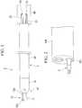
- FIG. 1is a schematic view showing a high-frequency treatment tool according to a first embodiment of the present invention.
- Fig. 2is a schematic view showing a state in which the high-frequency treatment tool according to the present embodiment is mounted in an endoscope.
- Fig. 3is a schematic view showing a partly cut treatment part of the high-frequency treatment tool according to the present embodiment.
- Fig. 4is a view seen from an arrow A of Fig. 3 .
- the high-frequency treatment tool 1is equipped with an insertion part 2 and a treatment part 10 that are insertable into a human body, and a drive assembly (manipulation part) 40.
- the treatment part 10is provided at a distal end side of the insertion part 2.
- the drive assembly 40is connected to the insertion part 2.
- the insertion part 2has an elongate shape with which it can be inserted into an interior of, for instance, a forceps channel 101 at an endoscope 100 (see Fig. 2 ) or another known manipulator. As shown in Fig. 1 , the insertion part 2 is equipped with a flexible tube part 30.
- a side at which the treatment part 10 is providedis referred to as a distal end of the insertion part 2
- a side opposite to the side at which the treatment part 10 is providedis referred to as a proximal end of the insertion part 2.
- the treatment part 10is equipped with a cover member 15, a first knife (first treatment member) 11, and a second knife (second treatment member) 12.
- the cover member 15is mounted on the distal end of the insertion part 2.
- the first and second knives 11 and 12are supported on the cover member 15 such that rotating manipulations can be performed independently of each other.
- the first knife 11is formed of, for example, a metal in a rod shape.
- the second knife 12is equipped with a main body 12a and an insulating chip 12b, and a distal end thereof is insulated.
- the main body 12ahas the same material and shape as the first knife 11.
- the insulating chip 12bis mounted on the distal end of the main body 12a.
- the first knife 11 and the second knife 12are connected to separate high-frequency power supplies (not shown) by electric wires 17 and 18 shown in Fig. 3 , and are supplied with high-frequency currents, thereby functioning as known high-frequency knives.
- the first knife 11is mounted on a first pulley 13.
- the first pulley 13is supported on a rotating shaft 14.
- the rotating shaft 14is supported on the cover member 15.
- the cover member 15is mounted on a distal end of a flexible tube part 30 and covers a proximal end side of the treatment part 10.
- a first wire (first transmission member) 21is wound around the first pulley 13 one turn or more, a part thereof is fixed.
- the first wire 21passes through the flexible tube part 30, protrudes from a proximal end side of the flexible tube part 30, and is wound around a first drive shaft 22.
- the first drive shaft 22is provided for a drive assembly 40, and is connected to a drive shaft of a drive mechanism such as a motor (not shown). If the drive mechanism is driven, the first drive shaft 22 is rotated, and the first wire 21 moves. As a result, the first pulley 13 and the first knife 11 mounted on the first pulley 13 are rotated about the rotating shaft 14.
- the second knife 12is mounted on a second pulley 16.
- the second pulley 16is disposed on approximately the same axis as the first pulley 13.
- a second wire (second transmission member) 23is wound around and fixed to the second pulley 16.
- the second wire 23is wound around a second drive shaft 24 provided for the drive assembly 40. The second wire 23 can rotate the second pulley 16 and the second knife 12 by rotating the second drive shaft 24.
- an insulating member 25is disposed between the first pulley 13 and the second pulley 16. An electric short-circuit between the first knife 11 and the second knife 12 through the first pulley 13 and the second pulley 16 is prevented by the insulating member 25. Also, the rotating shaft 14 is inserted into the first pulley 13 and the second pulley 16. The rotating shaft 14 is also configured so as not to cause the aforementioned electric short-circuit, for example, by forming it of an insulating material or performing insulating coating on an outer surface thereof.
- the first and second wires 21 and 23may be formed by suitably selecting a known material such as a metal or a resin.
- the first and second wires 21 and 23may be composed of the same material or different materials.
- the first and second pulleys 13 and 16can be rotated about the shaft 14.
- the first knife 11is evacuated such that a distal end thereof becomes a proximal end side relative to the rotating shaft 14.
- the first knife 11enters from a slot 15a provided in the cover member 15 into the cover member 15, and is housed in the cover member 15 as shown in Fig. 5A .
- the second knife 12can also be housed in the cover member 15.
- storage modethe state in which the first knife 11 and the second knife 12 are housed in the cover member 15 is referred to as storage mode.
- first knife 11 and the second knife 12are evacuated, a procedure such as incision can be performed using only the other high-frequency knife protruding from the cover member 15. Also, if the first knife 11 and the second knife 12 are not supplied with high-frequency currents, they can be used as pressing rods for dissecting the tissue.
- the tissue or the likecan be sandwiched and gripped between the first knife 11 and the second knife 12.
- the treatment part 10may function as common grasping forceps. If the currents are applied to the first and second knives 11 and 12, the treatment part 10 may function as coagulating forceps that apply heat to the sandwiched tissue.
- an operatorinserts the endoscope 100 into the mouth of a patient, and advances a distal end of the endoscope 100 to the vicinity of a treatment target portion.
- physiological salineis injected under the treatment target portion to distend tissue, and the target portion to be excised is separated from other tissues.
- the treatment part 10 of the high-frequency treatment tool 1is set in the storage mode, is inserted into the forceps channel 101 from, for instance, a forceps port of the proximal end side of the endoscope 100, and protrudes from a distal end of the endoscope 100.
- the forceps channel 101also frequently meanders in a body of the patient.
- the first knife 11 and the second knife 12can be easily inserted without damaging an inner wall of the forceps channel 101.
- the operatorWhile observing the target portion with the endoscope 100, the operator manipulates the drive assembly 40 to rotate the first pulley 13, and has only the first knife 11 protrude from the cover member 15 as shown in Fig. 5B .
- the distal end of the first knife 11comes into contact with the tissue, and the tissue is cauterized in a point shape and marked. Afterward, an incision is slowly made in the target portion by the first knife 11.
- the operatorputs the first knife 11 into the cover member 15, and has the second knife 12 protrude from the cover member 15 as shown in Fig. 5C . Then, resection of the target portion is conducted using the second knife 12. Since the distal end of the second knife 12 is provided with the insulating chip 12b, even if the distal end of the second knife 12 is exposed to the tissue, a resection procedure can be accurately performed without cauterizing the tissue.
- the first and second knives 11 and 12may be used as the coagulating forceps as needed. Also, in a state in which the excised tissue is gripped by the first and second knives 11 and 12, the high-frequency treatment tool 1 is removed, and the tissue may be collected.
- the first and second pulleys 13 and 16are suitably rotated, and a direction in which the distal end of the treatment part 10 protrudes may be adjusted at the insertion part 2.
- the first and second knives 11 and 12may be inclined with respect to the axis of the insertion part 2, or perpendicular to the axis. Further, as shown in Fig. 6 , even when the first and second knives 11 and 12 function as the forceps, opening/closing positions and directions of the forceps may be appropriately changed.
- the first and second knives 11 and 12 of the treatment part 10can be rotated about the shaft 14. For this reason, angle adjustment can be performed without moving the endoscope 100 into which the high-frequency treatment tool 1 is inserted. That is, the shaft 14 functions as a joint for the angle adjustment. Further, one of the first knife 11 and the second knife 12 is rotated and evacuated, and thereby does not get in the way when a procedure is performed by the other. As a result, the procedure can be performed in an easy and suitable way while numerous functions are fulfilled in the treatment part 10.
- the aforementioned evacuating movement and the joint driving of each knifeare substantially the same movement. For this reason, both of the aforementioned evacuating movement and the joint driving of each knife can be conducted by the first and second wires 21 and 23 Therefore, even if the complicated movement of the treatment part 10 is possible, a structure in which an increase in the size of a device is limited can be achieved.
- the treatment part 10is used in the storage mode, damage to an inner wall of the channel or a catch to the inner wall is limited, and the treatment part 10 can be easily inserted.
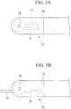
- Fig. 7is a view showing a partly cut distal end side of a high-frequency treatment tool 61 according to the present embodiment.
- Fig. 8is a view seen from an arrow B of Fig. 7.
- Fig. 8shows a structure of a treatment part 65 in which a cover member is excluded such that the structure can be more easily understood.
- the high-frequency treatment tool 61has a second member 62 mounted on a second pulley 16 instead of the second knife 12.
- the second member 62has a main body 62a and a distal end chip 62b that have the same shapes as the main body and the insulating chip at the second knife, respectively.
- the main body 62a and the distal end chip 62bare formed of an insulator, or surfaces thereof are coated by an insulating layer. Thereby, the main body 62a and the distal end chip 62b are formed to have an insulating property. No electric wire is connected to the second member 62, and no high-frequency current is supplied to the second member 62.
- the distal end chip 62b of the second member 62covers a distal end of the first knife 11 as shown in Fig. 7 .
- the first knife 11 and the second member 62are displaced in one body while the first knife 11 is supplied with a high-frequency current.
- the first knife 11 and the second member 62can function as a high-frequency knife whose distal end is insulated.
- a basic shape of the cover member 63is an approximately cylindrical shape as in the first embodiment.
- the cover member 63has a smaller dimension in an axis direction than the cover member 15 of the first embodiment, and has a shape in which a slot 63a thereof is also shorter than that of the cover member 15.
- the first knife 11 and the second member 62have structures in which any one thereof can be evacuated up to a position at which the one does not get in the way of the procedure using the other, but cannot be housed in the cover member 63.
- the high-frequency treatment tool 61is inserted into the endoscope 100.
- the treatment part 65 of the high-frequency treatment tool 61cannot be in a storage mode, the first knife 11 and the second member 62 are inserted in a state in which they are directed forward as in Fig. 7 .
- Fig. 9After the high-frequency treatment tool 61 is projected from the distal end of the endoscope 100, an operator rotates and evacuates the second member 62 as shown in Fig. 9 . Afterward, the operator performs a marking or an incision of target portion Tr using the first knife 11.
- Figs. 9 to 11a state in which the distended target portion Tr is viewed from above is shown.
- Fig. 9an example in which an incision is made by rotating the first knife 11 about the rotating shaft 14 is illustrated. However, as in the related art, the incision may be made by displacing the entirety of the endoscope 100 into which the high-frequency treatment tool 61 is inserted.
- Formation of the incision triggering resectionis completed, and then the operator rotates or manipulates the first knife 11 and the second member 62 to cover the distal end of the first knife 11 with the distal end chip 62b as shown in Fig. 10 .
- the operatorpenetrates the incision with the first knife 11 and the second member 62 functioning as the knife whose distal end is insulated, and proceeds to resection of the target portion Tr.
- Fig. 12is a view seen from an arrow C of Fig. 11 .
- the distal end of the first knife 11is insulated and covered by the distal end chip 62b. For this reason, for example, even when the high-frequency treatment tool 61 moves forward unintentionally, the target portion Tr is not excessively incised, and no perforation occurs.
- the incision and resectioncan also be performed by the first knife 11.
- the easy and suitable procedurecan be performed.
- first knife 11can also be used as the knife whose distal end is insulated, there is no need to consider, for instance, insulation of the first pulley 13 and the second pulley 16. For this reason, a structure of the treatment part can be simplified and used as a structure in which miniaturization is easier.
- an electrical type in functioning as the high-frequency knifeincludes any one of a monopolar type and a bipolar type.
- the high-frequency treatment toolis configured such that, for instance, in the knife to which the current is applied, the current is not automatically applied in the event of the evacuation or storage, and thereby manipulability of the high-frequency treatment tool can be improved.
- the high-frequency treatment toolsmay be configured such that, for instance, a contact with an electric wire for supplying power is provided on an outer circumferential surface of the pulley for which the knife is provided, for example, the contact comes into contact with the electric wire within a predetermined rotating range, and does not come into contact with the electric wire beyond the predetermined rotating range.
- the electric wire whose distal end is formed in a ring shapemay be locked on the rotating shaft, and the contact with the electric wire may be provided on an axial end face of the pulley.
- the high-frequency treatment toolmay be configured by providing a known water supply mechanism in the cover member such that the tissue attached to, for instance, the housed knife can be cleansed.
- the high-frequency treatment toolmay be configured by providing a handle or a dial knob with which the treatment part is manually driven on the drive shaft of the manipulation part.
- a target to which the high-frequency treatment tool of the present invention is applicableis not limited to the aforementioned endoscope.
- a medical system 200 as shown in Fig. 14may be configured by combining the high-frequency treatment tool with a master-slave type medical manipulator 201 having a soft insertion part 202.
- the medical manipulator 201 shown in Fig. 14is equipped with a master manipulator 211 and a slave manipulator 221.
- the master manipulator 211is manipulated by an operator Op.
- the slave manipulator 221is provided with the insertion part 202 having an observation mechanism.
- the master manipulator 211is equipped with a master arm 212, a display unit 213, and a control unit 214.
- the operator Opperforms manipulation input using the master arm 212.
- the display unit 213displays an image recorded using the observation mechanism of the insertion part 202.
- the control unit 214generates a manipulating instruction for operating the slave manipulator 221 based on movement of the master arm 212.
- the slave manipulator 221has a placement table 222 on which a patient P is placed, a polyarticular robot 223, and the insertion part 202.
- the polyarticular robot 223is disposed adjacent to the placement table 222.
- the insertion part 202is mounted on the polyarticular robot 223.
- the polyarticular robot 223 and the insertion part 202are operated according to a manipulation instruction sent from the master manipulator 211.
- the high-frequency treatment tool according to the present embodimentis inserted into an insertion hole 202a provided in a proximal end of the insertion part 202, and the manipulation part of the high-frequency treatment tool is mounted at a predetermined part of the polyarticular robot 223. Thereby, the treatment part of the high-frequency treatment tool can be manipulated using the master arm 212.
- the high-frequency treatment toolcan obtain more merits in combination with the manipulator equipped with the soft insertion part because of an advantage that the storage mode is given, and miniaturization of the treatment part is easy.
- the high-frequency treatment toolcan also be combined with a manipulator equipped with an insertion part having no flexibility.
- the procedurecan be performed in an easy and suitable way while fulfilling a plurality of functions in the treatment part.
Landscapes
- Health & Medical Sciences (AREA)
- Life Sciences & Earth Sciences (AREA)
- Surgery (AREA)
- Engineering & Computer Science (AREA)
- Plasma & Fusion (AREA)
- General Health & Medical Sciences (AREA)
- Otolaryngology (AREA)
- Physics & Mathematics (AREA)
- Veterinary Medicine (AREA)
- Biomedical Technology (AREA)
- Heart & Thoracic Surgery (AREA)
- Medical Informatics (AREA)
- Molecular Biology (AREA)
- Animal Behavior & Ethology (AREA)
- Nuclear Medicine, Radiotherapy & Molecular Imaging (AREA)
- Public Health (AREA)
- Cardiology (AREA)
- Surgical Instruments (AREA)
Description
- The present invention relates to a high-frequency treatment tool.
- Conventionally, performing various treatments on a treatment target portion by inserting various treatment tools into a channel of an endoscope and by projecting the various treatment tools from a distal end of the endoscope has been known. For example, as a treatment for dissecting tissue, one or more functions such as marking, incision, coagulation for hemostasis and tissue grasping of a target portion may be required for a single treatment. Since one treatment tool typically fulfills only one function, when the aforementioned treatment is performed, a removing action to remove a treatment tool that is in use at present to insert another treatment tool that is to be used next needs to be performed over and over again.
- In contrast, a treatment tool described in Patent Literature 1 is equipped with a pair of grasping members at a distal end thereof which are opened or closed by forward or backward movement, and a retractable acicular electrode between the pair of grasping members. With this constitution, the treatment tool described in Patent Literature 1 allows incision using the acicular electrode and tissue grasping using the grasping members to be performed by one treatment tool.
US 2004/102772 A1 concerns an apparatus and method for minimally invasive surgery using a cutting tool with rotational cutting edges. The surgical instrument includes a tube having a distal end and a cutting edge at the distal end. A handle is attached to the proximal end of the tube. Within the tube is a shaft having a longitudinally extending blade at its distal end that is adjacent to the distal end of the tube. The blade is revolvable about the longitudinal axis of the instrument to provide rotational cutting action. One or both of the blade and the cutting edge on the tube can be electrically energized to provide for electrocauterization of the body tissue being cut.US 5 241 968 A concerns surgical instruments that are provided with distal ends having a clevis and two discrete investment cast end effectors. One end effector is stationary relative to the clevis, and the other moves or rotates about a transverse pin of the clevis. The rotating end effector includes a first hole through which the transverse pin extends, and the surgical instrument includes an actuation mechanism for causing the rotating end effector to rotate about the transverse pin. The actuation mechanism includes a push rod which is either directly coupled to the proximal end of the rotating end effector or coupled by a staple element. The stationary second end effector, while including a first hole through which the transverse pin extends, has a boss which engages a hole in the clevis and is not coupled to the actuation mechanism.- Japanese Unexamined Patent Application, First Publication No.
H11-169381 - The treatment tool described in Patent Literature 1 allows the tissue grasping and the treatment using the acicular electrode to be performed by a single treatment tool. However, when an angle of the acicular electrode is adjusted to tissue, the entirety of an endoscope into which the treatment tool is inserted needs to be displaced, and manipulation becomes complicated. Also, since the grasping members cannot be housed in a sheath, the grasping members get in the way when a procedure using the acicular electrode is performed.
- A high-frequency treatment tool according to a first aspect of the present invention includes the features of claim 1.
Further aspects of the invention are described in the dependent claims. - A procedure can be performed in an easy and suitable way with the high-frequency treatment tool according to claim 1 while fulfilling a plurality of functions in the treatment part.
Fig. 1 is a schematic view showing a high-frequency treatment tool according to a first embodiment of the present invention.Fig. 2 is a schematic view showing a state in which the high-frequency treatment tool according to the first embodiment of the present invention is mounted on an endoscope.Fig. 3 is a schematic view showing a partly cut treatment part of the high-frequency treatment tool according to the first embodiment of the present invention.Fig. 4 is a view seen from an arrow A ofFig. 3 .Fig. 5A is a view showing a storage mode of the treatment part according to the first embodiment of the present invention.Fig. 5B is a view showing one form of treatment with the treatment part according to the first embodiment of the present invention.Fig. 5C is a view showing one form of treatment with the treatment part according to the first embodiment of the present invention.Fig. 6 is a view showing one form of use of the treatment part according to the first embodiment of the present invention.Fig. 7 is a schematic view showing a partly cut treatment part of a high-frequency treatment tool according to a second embodiment of the present invention.Fig. 8 is a view seen from an arrow B ofFig. 7 .Fig. 9 is a view showing one process in use of the high-frequency treatment tool according to the second embodiment of the present invention.Fig. 10 is a view showing one process in use of the high-frequency treatment tool according to the second embodiment of the present invention.Fig. 11 is a view showing one process in use of the high-frequency treatment tool according to the second embodiment of the present invention.Fig. 12 is a view showing one process in use of the high-frequency treatment tool according to the second embodiment of the present invention.Fig. 13 is a view showing one process in use of the high-frequency treatment tool according to the second embodiment of the present invention.Fig. 14 is a view showing a medical manipulator to which the high-frequency treatment tool of the present invention can be applied.- A first embodiment of a high-frequency treatment tool according to the present invention will be described with reference to
Figs. 1 to 6 .Fig. 1 is a schematic view showing a high-frequency treatment tool according to a first embodiment of the present invention.Fig. 2 is a schematic view showing a state in which the high-frequency treatment tool according to the present embodiment is mounted in an endoscope.Fig. 3 is a schematic view showing a partly cut treatment part of the high-frequency treatment tool according to the present embodiment.Fig. 4 is a view seen from an arrow A ofFig. 3 . - As shown in
Fig. 1 , the high-frequency treatment tool 1 is equipped with aninsertion part 2 and atreatment part 10 that are insertable into a human body, and a drive assembly (manipulation part) 40. Thetreatment part 10 is provided at a distal end side of theinsertion part 2. Thedrive assembly 40 is connected to theinsertion part 2. - The
insertion part 2 has an elongate shape with which it can be inserted into an interior of, for instance, aforceps channel 101 at an endoscope 100 (seeFig. 2 ) or another known manipulator. As shown inFig. 1 , theinsertion part 2 is equipped with aflexible tube part 30. Hereinafter, a side at which thetreatment part 10 is provided is referred to as a distal end of theinsertion part 2, and a side opposite to the side at which thetreatment part 10 is provided is referred to as a proximal end of theinsertion part 2. - The
treatment part 10 is equipped with acover member 15, a first knife (first treatment member) 11, and a second knife (second treatment member) 12. Thecover member 15 is mounted on the distal end of theinsertion part 2. The first andsecond knives cover member 15 such that rotating manipulations can be performed independently of each other. Thefirst knife 11 is formed of, for example, a metal in a rod shape. Thesecond knife 12 is equipped with amain body 12a and an insulatingchip 12b, and a distal end thereof is insulated. Themain body 12a has the same material and shape as thefirst knife 11. The insulatingchip 12b is mounted on the distal end of themain body 12a. Thefirst knife 11 and thesecond knife 12 are connected to separate high-frequency power supplies (not shown) byelectric wires Fig. 3 , and are supplied with high-frequency currents, thereby functioning as known high-frequency knives. - As shown in
Fig. 3 , thefirst knife 11 is mounted on afirst pulley 13. Thefirst pulley 13 is supported on arotating shaft 14. The rotatingshaft 14 is supported on thecover member 15. Thecover member 15 is mounted on a distal end of aflexible tube part 30 and covers a proximal end side of thetreatment part 10. In a state in which a
first wire (first transmission member) 21 is wound around thefirst pulley 13 one turn or more, a part thereof is fixed. As shown inFig. 1 , thefirst wire 21 passes through theflexible tube part 30, protrudes from a proximal end side of theflexible tube part 30, and is wound around afirst drive shaft 22. Thefirst drive shaft 22 is provided for adrive assembly 40, and is connected to a drive shaft of a drive mechanism such as a motor (not shown). If the drive mechanism is driven, thefirst drive shaft 22 is rotated, and thefirst wire 21 moves. As a result, thefirst pulley 13 and thefirst knife 11 mounted on thefirst pulley 13 are rotated about the rotatingshaft 14. - The
second knife 12 is mounted on asecond pulley 16. Thesecond pulley 16 is disposed on approximately the same axis as thefirst pulley 13. In the same way as thefirst wire 21, a second wire (second transmission member) 23 is wound around and fixed to thesecond pulley 16. In the same way as thefirst wire 21, thesecond wire 23 is wound around asecond drive shaft 24 provided for thedrive assembly 40. Thesecond wire 23 can rotate thesecond pulley 16 and thesecond knife 12 by rotating thesecond drive shaft 24. - As shown in
Fig. 4 , an insulatingmember 25 is disposed between thefirst pulley 13 and thesecond pulley 16. An electric short-circuit between thefirst knife 11 and thesecond knife 12 through thefirst pulley 13 and thesecond pulley 16 is prevented by the insulatingmember 25. Also, the rotatingshaft 14 is inserted into thefirst pulley 13 and thesecond pulley 16. The rotatingshaft 14 is also configured so as not to cause the aforementioned electric short-circuit, for example, by forming it of an insulating material or performing insulating coating on an outer surface thereof. - The first and
second wires second wires - An operation when the high-frequency treatment tool 1 configured as described above is used will be described.
- If the first and
second drive shafts drive assembly 40 are rotated via the drive mechanism, the first andsecond pulleys shaft 14. Thereby, if thefirst knife 11 is displaced to be separated from thesecond knife 12 in the state shown inFig. 3 , thefirst knife 11 is evacuated such that a distal end thereof becomes a proximal end side relative to therotating shaft 14. Further, thefirst knife 11 enters from aslot 15a provided in thecover member 15 into thecover member 15, and is housed in thecover member 15 as shown inFig. 5A . Similarly, thesecond knife 12 can also be housed in thecover member 15. Hereinafter, as inFig. 5A , the state in which thefirst knife 11 and thesecond knife 12 are housed in thecover member 15 is referred to as storage mode. - If only one of the
first knife 11 and thesecond knife 12 is evacuated, a procedure such as incision can be performed using only the other high-frequency knife protruding from thecover member 15. Also, if thefirst knife 11 and thesecond knife 12 are not supplied with high-frequency currents, they can be used as pressing rods for dissecting the tissue. - If the
first knife 11 and thesecond knife 12 are operated in cooperation with each other, the tissue or the like can be sandwiched and gripped between thefirst knife 11 and thesecond knife 12. At this time, if thefirst knife 11 and thesecond knife 12 are not supplied with the high-frequency currents, thetreatment part 10 may function as common grasping forceps. If the currents are applied to the first andsecond knives treatment part 10 may function as coagulating forceps that apply heat to the sandwiched tissue. - Next, an example of a procedure when performing endoscopic submucosal dissection (ESD) using the endoscope 100 and the high-frequency treatment tool 1 will be described.
- First, an operator inserts the endoscope 100 into the mouth of a patient, and advances a distal end of the endoscope 100 to the vicinity of a treatment target portion. Next, physiological saline is injected under the treatment target portion to distend tissue, and the target portion to be excised is separated from other tissues.
- Next, the
treatment part 10 of the high-frequency treatment tool 1 is set in the storage mode, is inserted into theforceps channel 101 from, for instance, a forceps port of the proximal end side of the endoscope 100, and protrudes from a distal end of the endoscope 100. When an insertion part of the endoscope 100 is soft, theforceps channel 101 also frequently meanders in a body of the patient. However, in the high-frequency treatment tool 1 according to the present embodiment, since thetreatment part 10 is set in the storage mode and is inserted into theforceps channel 101, thefirst knife 11 and thesecond knife 12 can be easily inserted without damaging an inner wall of theforceps channel 101. - While observing the target portion with the endoscope 100, the operator manipulates the
drive assembly 40 to rotate thefirst pulley 13, and has only thefirst knife 11 protrude from thecover member 15 as shown inFig. 5B . In a state in which a current is applied to thefirst knife 11, the distal end of thefirst knife 11 comes into contact with the tissue, and the tissue is cauterized in a point shape and marked. Afterward, an incision is slowly made in the target portion by thefirst knife 11. - After the incision is made to some extent, the operator puts the
first knife 11 into thecover member 15, and has thesecond knife 12 protrude from thecover member 15 as shown inFig. 5C . Then, resection of the target portion is conducted using thesecond knife 12. Since the distal end of thesecond knife 12 is provided with the insulatingchip 12b, even if the distal end of thesecond knife 12 is exposed to the tissue, a resection procedure can be accurately performed without cauterizing the tissue. - When bleeding occurs during resection, the first and
second knives second knives - In each process of the aforementioned procedure, the first and
second pulleys treatment part 10 protrudes may be adjusted at theinsertion part 2. For example, the first andsecond knives insertion part 2, or perpendicular to the axis. Further, as shown inFig. 6 , even when the first andsecond knives - In the high-frequency treatment tool 1 according to the present embodiment, the first and
second knives treatment part 10 can be rotated about theshaft 14. For this reason, angle adjustment can be performed without moving the endoscope 100 into which the high-frequency treatment tool 1 is inserted. That is, theshaft 14 functions as a joint for the angle adjustment. Further, one of thefirst knife 11 and thesecond knife 12 is rotated and evacuated, and thereby does not get in the way when a procedure is performed by the other. As a result, the procedure can be performed in an easy and suitable way while numerous functions are fulfilled in thetreatment part 10. - Also, the aforementioned evacuating movement and the joint driving of each knife are substantially the same movement. For this reason, both of the aforementioned evacuating movement and the joint driving of each knife can be conducted by the first and
second wires treatment part 10 is possible, a structure in which an increase in the size of a device is limited can be achieved. - In addition, even when the
treatment part 10 is inserted into a channel of a soft manipulator that is apt to meander, thetreatment part 10 is used in the storage mode, damage to an inner wall of the channel or a catch to the inner wall is limited, and thetreatment part 10 can be easily inserted. - Next, a second embodiment of the present invention will be described with reference to
Figs. 7 to 13 . In the following description, the same components as those that have already been described are given the same reference signs, and a duplicate description thereof will be omitted here. Fig. 7 is a view showing a partly cut distal end side of a high-frequency treatment tool 61 according to the present embodiment.Fig. 8 is a view seen from an arrow B ofFig. 7. Fig. 8 shows a structure of atreatment part 65 in which a cover member is excluded such that the structure can be more easily understood.- As shown in
Fig. 7 , the high-frequency treatment tool 61 has asecond member 62 mounted on asecond pulley 16 instead of thesecond knife 12. Thesecond member 62 has amain body 62a and adistal end chip 62b that have the same shapes as the main body and the insulating chip at the second knife, respectively. Themain body 62a and thedistal end chip 62b are formed of an insulator, or surfaces thereof are coated by an insulating layer. Thereby, themain body 62a and thedistal end chip 62b are formed to have an insulating property. No electric wire is connected to thesecond member 62, and no high-frequency current is supplied to thesecond member 62. - Since there is no need to secure insulation of the
first knife 11 and thesecond member 62, no insulating member is disposed between afirst pulley 13 and thesecond pulley 16 as shown inFig. 8 . - If a
first wire 21 and asecond wire 23 are manipulated to bring thefirst knife 11 and thesecond member 62 close to each other, thedistal end chip 62b of thesecond member 62 covers a distal end of thefirst knife 11 as shown inFig. 7 . In this state, thefirst knife 11 and thesecond member 62 are displaced in one body while thefirst knife 11 is supplied with a high-frequency current. Thereby, thefirst knife 11 and thesecond member 62 can function as a high-frequency knife whose distal end is insulated. - A basic shape of the
cover member 63 is an approximately cylindrical shape as in the first embodiment. However, thecover member 63 has a smaller dimension in an axis direction than thecover member 15 of the first embodiment, and has a shape in which aslot 63a thereof is also shorter than that of thecover member 15. For this reason, thefirst knife 11 and thesecond member 62 have structures in which any one thereof can be evacuated up to a position at which the one does not get in the way of the procedure using the other, but cannot be housed in thecover member 63. - An operation when the high-
frequency treatment tool 61 is used will be described taking the case of performing ESD as an example. First, like the first embodiment, a distal end of an endoscope 100 is advanced up to the vicinity of a treatment target portion, and the treatment target portion is distended. - Next, the high-
frequency treatment tool 61 is inserted into the endoscope 100. At this time, since thetreatment part 65 of the high-frequency treatment tool 61 cannot be in a storage mode, thefirst knife 11 and thesecond member 62 are inserted in a state in which they are directed forward as inFig. 7 . - After the high-
frequency treatment tool 61 is projected from the distal end of the endoscope 100, an operator rotates and evacuates thesecond member 62 as shown inFig. 9 . Afterward, the operator performs a marking or an incision of target portion Tr using thefirst knife 11. InFigs. 9 to 11 , a state in which the distended target portion Tr is viewed from above is shown. InFig. 9 , an example in which an incision is made by rotating thefirst knife 11 about the rotatingshaft 14 is illustrated. However, as in the related art, the incision may be made by displacing the entirety of the endoscope 100 into which the high-frequency treatment tool 61 is inserted. - Formation of the incision triggering resection is completed, and then the operator rotates or manipulates the
first knife 11 and thesecond member 62 to cover the distal end of thefirst knife 11 with thedistal end chip 62b as shown inFig. 10 . As shown inFig. 11 , the operator penetrates the incision with thefirst knife 11 and thesecond member 62 functioning as the knife whose distal end is insulated, and proceeds to resection of the target portion Tr.Fig. 12 is a view seen from an arrow C ofFig. 11 . As shown inFig. 12 , the distal end of thefirst knife 11 is insulated and covered by thedistal end chip 62b. For this reason, for example, even when the high-frequency treatment tool 61 moves forward unintentionally, the target portion Tr is not excessively incised, and no perforation occurs. - In addition, as shown in
Fig. 13 , while a part of the target portion Tr is being excluded by thesecond member 62, the incision and resection can also be performed by thefirst knife 11. - Even in the high-
frequency treatment tool 61 according to the present embodiment, like the first embodiment, the easy and suitable procedure can be performed. - Also, since the
first knife 11 can also be used as the knife whose distal end is insulated, there is no need to consider, for instance, insulation of thefirst pulley 13 and thesecond pulley 16. For this reason, a structure of the treatment part can be simplified and used as a structure in which miniaturization is easier. - Although embodiments of the present invention have been described, the present invention is not limited to the above embodiments.
- For example, in the high-frequency treatment tool of the present invention, an electrical type in functioning as the high-frequency knife includes any one of a monopolar type and a bipolar type.
- The high-frequency treatment tool is configured such that, for instance, in the knife to which the current is applied, the current is not automatically applied in the event of the evacuation or storage, and thereby manipulability of the high-frequency treatment tool can be improved. For example, the high-frequency treatment tools may be configured such that, for instance, a contact with an electric wire for supplying power is provided on an outer circumferential surface of the pulley for which the knife is provided, for example, the contact comes into contact with the electric wire within a predetermined rotating range, and does not come into contact with the electric wire beyond the predetermined rotating range.
- In the high-frequency treatment tool, the electric wire whose distal end is formed in a ring shape may be locked on the rotating shaft, and the contact with the electric wire may be provided on an axial end face of the pulley. Thereby, in the high-frequency treatment tool, since the contact is not in contact with the electric wire when located in a ring formed at the distal end of the electric wire, an angle range of the treatment part capable of supplying power can be adjusted by the ring shape of the distal end of the electric wire.
- The high-frequency treatment tool may be configured by providing a known water supply mechanism in the cover member such that the tissue attached to, for instance, the housed knife can be cleansed.
- The high-frequency treatment tool may be configured by providing a handle or a dial knob with which the treatment part is manually driven on the drive shaft of the manipulation part.
- A target to which the high-frequency treatment tool of the present invention is applicable is not limited to the aforementioned endoscope. For example, a
medical system 200 as shown inFig. 14 may be configured by combining the high-frequency treatment tool with a master-slave typemedical manipulator 201 having asoft insertion part 202. Themedical manipulator 201 shown inFig. 14 is equipped with amaster manipulator 211 and aslave manipulator 221. Themaster manipulator 211 is manipulated by an operator Op. Theslave manipulator 221 is provided with theinsertion part 202 having an observation mechanism. - The
master manipulator 211 is equipped with amaster arm 212, adisplay unit 213, and acontrol unit 214. The operator Op performs manipulation input using themaster arm 212. Thedisplay unit 213 displays an image recorded using the observation mechanism of theinsertion part 202. Thecontrol unit 214 generates a manipulating instruction for operating theslave manipulator 221 based on movement of themaster arm 212. - The
slave manipulator 221 has a placement table 222 on which a patient P is placed, a polyarticular robot 223, and theinsertion part 202. The polyarticular robot 223 is disposed adjacent to the placement table 222. Theinsertion part 202 is mounted on the polyarticular robot 223. The polyarticular robot 223 and theinsertion part 202 are operated according to a manipulation instruction sent from themaster manipulator 211. The high-frequency treatment tool according to the present embodiment is inserted into aninsertion hole 202a provided in a proximal end of theinsertion part 202, and the manipulation part of the high-frequency treatment tool is mounted at a predetermined part of the polyarticular robot 223. Thereby, the treatment part of the high-frequency treatment tool can be manipulated using themaster arm 212. - The high-frequency treatment tool can obtain more merits in combination with the manipulator equipped with the soft insertion part because of an advantage that the storage mode is given, and miniaturization of the treatment part is easy. In addition, the high-frequency treatment tool can also be combined with a manipulator equipped with an insertion part having no flexibility.
- Although embodiments of the present invention have been described above in detail with reference to the drawings, the specific constitution is not limited to these embodiments. The invention is defined by the appended claims.
- Using the high-frequency treatment tool, the procedure can be performed in an easy and suitable way while fulfilling a plurality of functions in the treatment part.
- 1:
- high-frequency treatment tool
- 2:
- insertion part
- 10:
- treatment part
- 40:
- drive assembly (manipulation part)
- 15:
- cover member
- 11:
- first knife (first treatment member)
- 12:
- second knife (second treatment member)
- 12a, 62a:
- main body
- 12b, 62b:
- insulating chip
- 21:
- first wire (first transmission member)
- 22:
- first drive shaft
- 23:
- second wire (second transmission member)
- 24:
- second drive shaft
Claims (4)
- A high-frequency treatment tool (1; 61) comprising:a longitudinal insertion part (2); a manipulation part (40) which is coupled to the insertion part (2); a treatment part (10; 65) which is provided at a distal end portion of the insertion part (2), wherebythe treatment part (10; 65) includes:a cover member (15) which is mounted on the distal end portion of the insertion part (2);a first treatment member (11) which is rotatably supported within the cover member (15), which is configured to rotate about a shaft (14), and to which a high-frequency current is capable of being applied; anda second member (12; 62) which is configured to rotate about the shaft (14), the second member (12; 62) including a rod-shaped main body (12a; 62a), andthe manipulation part (40) includes:a first drive shaft (22) that is connected to the first treatment member (11) by a first transmission member (21) and rotatably driven to rotate the first treatment member (11); anda second drive shaft (24) that is connected to the second member (12; 62) by a second transmission member (23) and rotatably driven to rotate the second member (12; 62),characterized in that the second member is rotatably supported within the cover member (15) andin that the second member includes an insulating chip (12b; 62b) mounted on a distal end of the main body (12a; 62a).
- The high-frequency treatment tool (1; 61) according to claim 1, wherein the first treatment member (11) and the second member (12; 62) are rotatable to enter the cover member (15) to assume storage positions.
- The high-frequency treatment tool (1; 61) according to claim 2, wherein the high-frequency treatment tool (1; 61) is configured to interrupt a supply of the high-frequency current when the first treatment member (11) is stored.
- The high-frequency treatment tool (61) according to claim 1, wherein:the main body (62a) of the second member (62) is formed of an insulating material; anda distal end portion of the first treatment member (11) is configured to be covered by the insulating chip (62b) in a state where the first treatment member (11) and the second member (62) approach each other.
Applications Claiming Priority (2)
| Application Number | Priority Date | Filing Date | Title |
|---|---|---|---|
| US201361806504P | 2013-03-29 | 2013-03-29 | |
| PCT/JP2014/050320WO2014156219A1 (en) | 2013-03-29 | 2014-01-10 | High-frequency treatment tool |
Publications (3)
| Publication Number | Publication Date |
|---|---|
| EP2979658A1 EP2979658A1 (en) | 2016-02-03 |
| EP2979658A4 EP2979658A4 (en) | 2016-11-23 |
| EP2979658B1true EP2979658B1 (en) | 2018-03-07 |
Family
ID=51623225
Family Applications (1)
| Application Number | Title | Priority Date | Filing Date |
|---|---|---|---|
| EP14776556.4ANot-in-forceEP2979658B1 (en) | 2013-03-29 | 2014-01-10 | High-frequency treatment tool with two rotatable members and with an insulating chip |
Country Status (5)
| Country | Link |
|---|---|
| US (1) | US20160008068A1 (en) |
| EP (1) | EP2979658B1 (en) |
| JP (1) | JP5948493B2 (en) |
| CN (1) | CN105073048B (en) |
| WO (1) | WO2014156219A1 (en) |
Families Citing this family (8)
| Publication number | Priority date | Publication date | Assignee | Title |
|---|---|---|---|---|
| EP2807989B1 (en) | 2011-11-23 | 2020-09-30 | Livsmed Inc. | Surgical instrument |
| KR101584766B1 (en) | 2014-04-24 | 2016-01-12 | 주식회사 리브스메드 | Surgical instrument |
| US10709467B2 (en) | 2014-10-02 | 2020-07-14 | Livsmed Inc. | Surgical instrument |
| CN105559888B (en)* | 2014-10-30 | 2019-11-22 | 香港中文大学 | robot system |
| US11344381B2 (en) | 2015-02-17 | 2022-05-31 | Livsmed Inc. | Instrument for surgery |
| KR102153407B1 (en) | 2015-02-17 | 2020-09-08 | 주식회사 리브스메드 | Surgical instrument |
| US11896336B2 (en) | 2015-02-17 | 2024-02-13 | Livsmed Inc. | Instrument for surgery |
| KR102191482B1 (en) | 2017-11-14 | 2020-12-15 | 주식회사 리브스메드 | Roll Joint Member for Surgical instrument |
Family Cites Families (16)
| Publication number | Priority date | Publication date | Assignee | Title |
|---|---|---|---|---|
| US5241968A (en)* | 1990-05-10 | 1993-09-07 | Symbiosis Corporation | Single acting endoscopic instruments |
| US5275608A (en)* | 1991-10-16 | 1994-01-04 | Implemed, Inc. | Generic endoscopic instrument |
| ATE209875T1 (en)* | 1993-07-21 | 2001-12-15 | Charles H Klieman | SURGICAL INSTRUMENT FOR ENDOSCOPIC AND GENERAL OPERATIONS |
| US6726686B2 (en)* | 1997-11-12 | 2004-04-27 | Sherwood Services Ag | Bipolar electrosurgical instrument for sealing vessels |
| JPH11169381A (en)* | 1997-12-15 | 1999-06-29 | Olympus Optical Co Ltd | High frequency treating device |
| US6428539B1 (en)* | 2000-03-09 | 2002-08-06 | Origin Medsystems, Inc. | Apparatus and method for minimally invasive surgery using rotational cutting tool |
| US6551313B1 (en)* | 2001-05-02 | 2003-04-22 | John M. Levin | Electrosurgical instrument with separate cutting and coagulating members |
| US6712759B2 (en)* | 2002-01-07 | 2004-03-30 | Acmi Corporation | Outflow system for an endoscope |
| US7582086B2 (en)* | 2004-10-20 | 2009-09-01 | Atricure, Inc. | Surgical clamp |
| US20070282336A1 (en)* | 2006-05-30 | 2007-12-06 | Pentax Corporation | Bipolar high-frequency treatment tool for endoscope |
| JP4543017B2 (en)* | 2006-06-12 | 2010-09-15 | 有限会社リバー精工 | Endoscopic high-frequency incision tool |
| JP2009247696A (en)* | 2008-04-08 | 2009-10-29 | Olympus Medical Systems Corp | High-frequency treatment equipment |
| US8771270B2 (en)* | 2008-07-16 | 2014-07-08 | Intuitive Surgical Operations, Inc. | Bipolar cautery instrument |
| JP2010268845A (en)* | 2009-05-19 | 2010-12-02 | Hoya Corp | High frequency knife for endoscope |
| US8936614B2 (en)* | 2010-12-30 | 2015-01-20 | Covidien Lp | Combined unilateral/bilateral jaws on a surgical instrument |
| US9072524B2 (en)* | 2012-06-29 | 2015-07-07 | Covidien Lp | Surgical forceps |
- 2014
- 2014-01-10CNCN201480017951.8Apatent/CN105073048B/enactiveActive
- 2014-01-10EPEP14776556.4Apatent/EP2979658B1/ennot_activeNot-in-force
- 2014-01-10WOPCT/JP2014/050320patent/WO2014156219A1/enactiveApplication Filing
- 2014-01-10JPJP2015508106Apatent/JP5948493B2/enactiveActive
- 2015
- 2015-09-23USUS14/862,377patent/US20160008068A1/ennot_activeAbandoned
Also Published As
| Publication number | Publication date |
|---|---|
| WO2014156219A1 (en) | 2014-10-02 |
| CN105073048A (en) | 2015-11-18 |
| EP2979658A4 (en) | 2016-11-23 |
| EP2979658A1 (en) | 2016-02-03 |
| JPWO2014156219A1 (en) | 2017-02-16 |
| JP5948493B2 (en) | 2016-07-06 |
| US20160008068A1 (en) | 2016-01-14 |
| CN105073048B (en) | 2017-07-14 |
Similar Documents
| Publication | Publication Date | Title |
|---|---|---|
| EP2979658B1 (en) | High-frequency treatment tool with two rotatable members and with an insulating chip | |
| US20210290299A1 (en) | Vessel sealing instrument with suction system | |
| US7033357B2 (en) | Apparatus and method for minimally invasive surgery using rotational cutting tool | |
| JP4315557B2 (en) | Medical treatment tool | |
| KR101022553B1 (en) | Endoscopic treatment tools | |
| KR102110472B1 (en) | Bipolar cautery instrument | |
| US5573535A (en) | Bipolar surgical instrument for coagulation and cutting | |
| WO2014080862A1 (en) | Tissue ablation apparatus | |
| US7955328B2 (en) | Tissue dissector and/or coagulator with a slit in an insulating tip to control the direction of energy | |
| EP2756816B1 (en) | High-frequency treatment instrument | |
| EP1948027B1 (en) | Tissue cutting devices having hemostasis capability | |
| US6346106B1 (en) | Instrument and method employing snare electrode windable about rotatable spool for minimally invasive electrosurgical resection | |
| US9987076B2 (en) | Multi-function surgical instruments | |
| JP2002113015A (en) | High frequency endo-therapy accessory | |
| JP5290658B2 (en) | Endoscopic treatment tool | |
| EP3653144A1 (en) | Dissection device for tissue | |
| EP3031420B1 (en) | Energizable attachment for surgical devices | |
| US9974524B2 (en) | Thoracic biopsy instrument with bipolar sealing and blade technology | |
| US20160089119A1 (en) | Energy-based lymph node dissection device | |
| WO2014052809A1 (en) | Surgical dissector device | |
| EP3583885B1 (en) | Visualization devices | |
| US11350982B2 (en) | Electrosurgical forceps | |
| JP3211674U (en) | Surgical scissors | |
| US11969203B2 (en) | Colpotomy system with applied energy | |
| US20240390060A1 (en) | Surgical cautery and cutting device |
Legal Events
| Date | Code | Title | Description |
|---|---|---|---|
| PUAI | Public reference made under article 153(3) epc to a published international application that has entered the european phase | Free format text:ORIGINAL CODE: 0009012 | |
| 17P | Request for examination filed | Effective date:20150930 | |
| AK | Designated contracting states | Kind code of ref document:A1 Designated state(s):AL AT BE BG CH CY CZ DE DK EE ES FI FR GB GR HR HU IE IS IT LI LT LU LV MC MK MT NL NO PL PT RO RS SE SI SK SM TR | |
| AX | Request for extension of the european patent | Extension state:BA ME | |
| DAX | Request for extension of the european patent (deleted) | ||
| RAP1 | Party data changed (applicant data changed or rights of an application transferred) | Owner name:OLYMPUS CORPORATION | |
| REG | Reference to a national code | Ref country code:DE Ref legal event code:R079 Ref document number:602014022095 Country of ref document:DE Free format text:PREVIOUS MAIN CLASS: A61B0018120000 Ipc:A61B0017000000 | |
| A4 | Supplementary search report drawn up and despatched | Effective date:20161024 | |
| RIC1 | Information provided on ipc code assigned before grant | Ipc:A61B 17/29 20060101ALI20161018BHEP Ipc:A61B 18/14 20060101ALI20161018BHEP Ipc:A61B 17/00 20060101AFI20161018BHEP Ipc:A61B 18/00 20060101ALI20161018BHEP | |
| RIN1 | Information on inventor provided before grant (corrected) | Inventor name:KISHI, KOSUKE Inventor name:HYODO, RYOJI | |
| GRAP | Despatch of communication of intention to grant a patent | Free format text:ORIGINAL CODE: EPIDOSNIGR1 | |
| STAA | Information on the status of an ep patent application or granted ep patent | Free format text:STATUS: GRANT OF PATENT IS INTENDED | |
| INTG | Intention to grant announced | Effective date:20171013 | |
| RIN1 | Information on inventor provided before grant (corrected) | Inventor name:KISHI, KOSUKE Inventor name:HYODO, RYOJI | |
| GRAS | Grant fee paid | Free format text:ORIGINAL CODE: EPIDOSNIGR3 | |
| GRAA | (expected) grant | Free format text:ORIGINAL CODE: 0009210 | |
| STAA | Information on the status of an ep patent application or granted ep patent | Free format text:STATUS: THE PATENT HAS BEEN GRANTED | |
| AK | Designated contracting states | Kind code of ref document:B1 Designated state(s):AL AT BE BG CH CY CZ DE DK EE ES FI FR GB GR HR HU IE IS IT LI LT LU LV MC MK MT NL NO PL PT RO RS SE SI SK SM TR | |
| REG | Reference to a national code | Ref country code:GB Ref legal event code:FG4D | |
| REG | Reference to a national code | Ref country code:CH Ref legal event code:EP Ref country code:AT Ref legal event code:REF Ref document number:975663 Country of ref document:AT Kind code of ref document:T Effective date:20180315 | |
| REG | Reference to a national code | Ref country code:IE Ref legal event code:FG4D | |
| REG | Reference to a national code | Ref country code:DE Ref legal event code:R096 Ref document number:602014022095 Country of ref document:DE | |
| REG | Reference to a national code | Ref country code:NL Ref legal event code:MP Effective date:20180307 | |
| REG | Reference to a national code | Ref country code:LT Ref legal event code:MG4D | |
| PG25 | Lapsed in a contracting state [announced via postgrant information from national office to epo] | Ref country code:NO Free format text:LAPSE BECAUSE OF FAILURE TO SUBMIT A TRANSLATION OF THE DESCRIPTION OR TO PAY THE FEE WITHIN THE PRESCRIBED TIME-LIMIT Effective date:20180607 Ref country code:CY Free format text:LAPSE BECAUSE OF FAILURE TO SUBMIT A TRANSLATION OF THE DESCRIPTION OR TO PAY THE FEE WITHIN THE PRESCRIBED TIME-LIMIT Effective date:20180307 Ref country code:LT Free format text:LAPSE BECAUSE OF FAILURE TO SUBMIT A TRANSLATION OF THE DESCRIPTION OR TO PAY THE FEE WITHIN THE PRESCRIBED TIME-LIMIT Effective date:20180307 Ref country code:HR Free format text:LAPSE BECAUSE OF FAILURE TO SUBMIT A TRANSLATION OF THE DESCRIPTION OR TO PAY THE FEE WITHIN THE PRESCRIBED TIME-LIMIT Effective date:20180307 Ref country code:ES Free format text:LAPSE BECAUSE OF FAILURE TO SUBMIT A TRANSLATION OF THE DESCRIPTION OR TO PAY THE FEE WITHIN THE PRESCRIBED TIME-LIMIT Effective date:20180307 Ref country code:FI Free format text:LAPSE BECAUSE OF FAILURE TO SUBMIT A TRANSLATION OF THE DESCRIPTION OR TO PAY THE FEE WITHIN THE PRESCRIBED TIME-LIMIT Effective date:20180307 | |
| REG | Reference to a national code | Ref country code:AT Ref legal event code:MK05 Ref document number:975663 Country of ref document:AT Kind code of ref document:T Effective date:20180307 | |
| PG25 | Lapsed in a contracting state [announced via postgrant information from national office to epo] | Ref country code:GR Free format text:LAPSE BECAUSE OF FAILURE TO SUBMIT A TRANSLATION OF THE DESCRIPTION OR TO PAY THE FEE WITHIN THE PRESCRIBED TIME-LIMIT Effective date:20180608 Ref country code:LV Free format text:LAPSE BECAUSE OF FAILURE TO SUBMIT A TRANSLATION OF THE DESCRIPTION OR TO PAY THE FEE WITHIN THE PRESCRIBED TIME-LIMIT Effective date:20180307 Ref country code:SE Free format text:LAPSE BECAUSE OF FAILURE TO SUBMIT A TRANSLATION OF THE DESCRIPTION OR TO PAY THE FEE WITHIN THE PRESCRIBED TIME-LIMIT Effective date:20180307 Ref country code:BG Free format text:LAPSE BECAUSE OF FAILURE TO SUBMIT A TRANSLATION OF THE DESCRIPTION OR TO PAY THE FEE WITHIN THE PRESCRIBED TIME-LIMIT Effective date:20180607 Ref country code:RS Free format text:LAPSE BECAUSE OF FAILURE TO SUBMIT A TRANSLATION OF THE DESCRIPTION OR TO PAY THE FEE WITHIN THE PRESCRIBED TIME-LIMIT Effective date:20180307 | |
| PG25 | Lapsed in a contracting state [announced via postgrant information from national office to epo] | Ref country code:NL Free format text:LAPSE BECAUSE OF FAILURE TO SUBMIT A TRANSLATION OF THE DESCRIPTION OR TO PAY THE FEE WITHIN THE PRESCRIBED TIME-LIMIT Effective date:20180307 Ref country code:PL Free format text:LAPSE BECAUSE OF FAILURE TO SUBMIT A TRANSLATION OF THE DESCRIPTION OR TO PAY THE FEE WITHIN THE PRESCRIBED TIME-LIMIT Effective date:20180307 Ref country code:AL Free format text:LAPSE BECAUSE OF FAILURE TO SUBMIT A TRANSLATION OF THE DESCRIPTION OR TO PAY THE FEE WITHIN THE PRESCRIBED TIME-LIMIT Effective date:20180307 Ref country code:RO Free format text:LAPSE BECAUSE OF FAILURE TO SUBMIT A TRANSLATION OF THE DESCRIPTION OR TO PAY THE FEE WITHIN THE PRESCRIBED TIME-LIMIT Effective date:20180307 Ref country code:EE Free format text:LAPSE BECAUSE OF FAILURE TO SUBMIT A TRANSLATION OF THE DESCRIPTION OR TO PAY THE FEE WITHIN THE PRESCRIBED TIME-LIMIT Effective date:20180307 | |
| PG25 | Lapsed in a contracting state [announced via postgrant information from national office to epo] | Ref country code:CZ Free format text:LAPSE BECAUSE OF FAILURE TO SUBMIT A TRANSLATION OF THE DESCRIPTION OR TO PAY THE FEE WITHIN THE PRESCRIBED TIME-LIMIT Effective date:20180307 Ref country code:AT Free format text:LAPSE BECAUSE OF FAILURE TO SUBMIT A TRANSLATION OF THE DESCRIPTION OR TO PAY THE FEE WITHIN THE PRESCRIBED TIME-LIMIT Effective date:20180307 Ref country code:SM Free format text:LAPSE BECAUSE OF FAILURE TO SUBMIT A TRANSLATION OF THE DESCRIPTION OR TO PAY THE FEE WITHIN THE PRESCRIBED TIME-LIMIT Effective date:20180307 Ref country code:SK Free format text:LAPSE BECAUSE OF FAILURE TO SUBMIT A TRANSLATION OF THE DESCRIPTION OR TO PAY THE FEE WITHIN THE PRESCRIBED TIME-LIMIT Effective date:20180307 | |
| REG | Reference to a national code | Ref country code:DE Ref legal event code:R097 Ref document number:602014022095 Country of ref document:DE | |
| PG25 | Lapsed in a contracting state [announced via postgrant information from national office to epo] | Ref country code:PT Free format text:LAPSE BECAUSE OF FAILURE TO SUBMIT A TRANSLATION OF THE DESCRIPTION OR TO PAY THE FEE WITHIN THE PRESCRIBED TIME-LIMIT Effective date:20180709 | |
| PLBE | No opposition filed within time limit | Free format text:ORIGINAL CODE: 0009261 | |
| STAA | Information on the status of an ep patent application or granted ep patent | Free format text:STATUS: NO OPPOSITION FILED WITHIN TIME LIMIT | |
| PG25 | Lapsed in a contracting state [announced via postgrant information from national office to epo] | Ref country code:DK Free format text:LAPSE BECAUSE OF FAILURE TO SUBMIT A TRANSLATION OF THE DESCRIPTION OR TO PAY THE FEE WITHIN THE PRESCRIBED TIME-LIMIT Effective date:20180307 | |
| 26N | No opposition filed | Effective date:20181210 | |
| PG25 | Lapsed in a contracting state [announced via postgrant information from national office to epo] | Ref country code:IT Free format text:LAPSE BECAUSE OF FAILURE TO SUBMIT A TRANSLATION OF THE DESCRIPTION OR TO PAY THE FEE WITHIN THE PRESCRIBED TIME-LIMIT Effective date:20180307 Ref country code:SI Free format text:LAPSE BECAUSE OF FAILURE TO SUBMIT A TRANSLATION OF THE DESCRIPTION OR TO PAY THE FEE WITHIN THE PRESCRIBED TIME-LIMIT Effective date:20180307 | |
| PGFP | Annual fee paid to national office [announced via postgrant information from national office to epo] | Ref country code:DE Payment date:20190129 Year of fee payment:6 | |
| PG25 | Lapsed in a contracting state [announced via postgrant information from national office to epo] | Ref country code:MC Free format text:LAPSE BECAUSE OF FAILURE TO SUBMIT A TRANSLATION OF THE DESCRIPTION OR TO PAY THE FEE WITHIN THE PRESCRIBED TIME-LIMIT Effective date:20180307 | |
| REG | Reference to a national code | Ref country code:CH Ref legal event code:PL | |
| GBPC | Gb: european patent ceased through non-payment of renewal fee | Effective date:20190110 | |
| PG25 | Lapsed in a contracting state [announced via postgrant information from national office to epo] | Ref country code:LU Free format text:LAPSE BECAUSE OF NON-PAYMENT OF DUE FEES Effective date:20190110 | |
| REG | Reference to a national code | Ref country code:BE Ref legal event code:MM Effective date:20190131 | |
| REG | Reference to a national code | Ref country code:IE Ref legal event code:MM4A | |
| PG25 | Lapsed in a contracting state [announced via postgrant information from national office to epo] | Ref country code:FR Free format text:LAPSE BECAUSE OF NON-PAYMENT OF DUE FEES Effective date:20190131 | |
| PG25 | Lapsed in a contracting state [announced via postgrant information from national office to epo] | Ref country code:BE Free format text:LAPSE BECAUSE OF NON-PAYMENT OF DUE FEES Effective date:20190131 | |
| PG25 | Lapsed in a contracting state [announced via postgrant information from national office to epo] | Ref country code:CH Free format text:LAPSE BECAUSE OF NON-PAYMENT OF DUE FEES Effective date:20190131 Ref country code:LI Free format text:LAPSE BECAUSE OF NON-PAYMENT OF DUE FEES Effective date:20190131 Ref country code:GB Free format text:LAPSE BECAUSE OF NON-PAYMENT OF DUE FEES Effective date:20190110 | |
| PG25 | Lapsed in a contracting state [announced via postgrant information from national office to epo] | Ref country code:IE Free format text:LAPSE BECAUSE OF NON-PAYMENT OF DUE FEES Effective date:20190110 | |
| PG25 | Lapsed in a contracting state [announced via postgrant information from national office to epo] | Ref country code:TR Free format text:LAPSE BECAUSE OF FAILURE TO SUBMIT A TRANSLATION OF THE DESCRIPTION OR TO PAY THE FEE WITHIN THE PRESCRIBED TIME-LIMIT Effective date:20180307 | |
| PG25 | Lapsed in a contracting state [announced via postgrant information from national office to epo] | Ref country code:MT Free format text:LAPSE BECAUSE OF NON-PAYMENT OF DUE FEES Effective date:20190110 | |
| REG | Reference to a national code | Ref country code:DE Ref legal event code:R119 Ref document number:602014022095 Country of ref document:DE | |
| PG25 | Lapsed in a contracting state [announced via postgrant information from national office to epo] | Ref country code:DE Free format text:LAPSE BECAUSE OF NON-PAYMENT OF DUE FEES Effective date:20200801 | |
| PG25 | Lapsed in a contracting state [announced via postgrant information from national office to epo] | Ref country code:IS Free format text:LAPSE BECAUSE OF FAILURE TO SUBMIT A TRANSLATION OF THE DESCRIPTION OR TO PAY THE FEE WITHIN THE PRESCRIBED TIME-LIMIT Effective date:20180707 | |
| PG25 | Lapsed in a contracting state [announced via postgrant information from national office to epo] | Ref country code:HU Free format text:LAPSE BECAUSE OF FAILURE TO SUBMIT A TRANSLATION OF THE DESCRIPTION OR TO PAY THE FEE WITHIN THE PRESCRIBED TIME-LIMIT; INVALID AB INITIO Effective date:20140110 | |
| PG25 | Lapsed in a contracting state [announced via postgrant information from national office to epo] | Ref country code:MK Free format text:LAPSE BECAUSE OF FAILURE TO SUBMIT A TRANSLATION OF THE DESCRIPTION OR TO PAY THE FEE WITHIN THE PRESCRIBED TIME-LIMIT Effective date:20180307 |