EP2976877B1 - Guided filter-based detail enhancement - Google Patents
Guided filter-based detail enhancementDownload PDFInfo
- Publication number
- EP2976877B1 EP2976877B1EP14769741.1AEP14769741AEP2976877B1EP 2976877 B1EP2976877 B1EP 2976877B1EP 14769741 AEP14769741 AEP 14769741AEP 2976877 B1EP2976877 B1EP 2976877B1
- Authority
- EP
- European Patent Office
- Prior art keywords
- signal
- detail
- variance
- video signal
- input video
- Prior art date
- Legal status (The legal status is an assumption and is not a legal conclusion. Google has not performed a legal analysis and makes no representation as to the accuracy of the status listed.)
- Active
Links
Images


Classifications
- H—ELECTRICITY
- H04—ELECTRIC COMMUNICATION TECHNIQUE
- H04N—PICTORIAL COMMUNICATION, e.g. TELEVISION
- H04N5/00—Details of television systems
- H04N5/14—Picture signal circuitry for video frequency region
- H04N5/142—Edging; Contouring
- G—PHYSICS
- G06—COMPUTING OR CALCULATING; COUNTING
- G06T—IMAGE DATA PROCESSING OR GENERATION, IN GENERAL
- G06T5/00—Image enhancement or restoration
- G06T5/73—Deblurring; Sharpening
- H—ELECTRICITY
- H04—ELECTRIC COMMUNICATION TECHNIQUE
- H04N—PICTORIAL COMMUNICATION, e.g. TELEVISION
- H04N5/00—Details of television systems
- H04N5/14—Picture signal circuitry for video frequency region
- H04N5/20—Circuitry for controlling amplitude response
- H04N5/205—Circuitry for controlling amplitude response for correcting amplitude versus frequency characteristic
- H04N5/208—Circuitry for controlling amplitude response for correcting amplitude versus frequency characteristic for compensating for attenuation of high frequency components, e.g. crispening, aperture distortion correction
- G—PHYSICS
- G06—COMPUTING OR CALCULATING; COUNTING
- G06T—IMAGE DATA PROCESSING OR GENERATION, IN GENERAL
- G06T2207/00—Indexing scheme for image analysis or image enhancement
- G06T2207/10—Image acquisition modality
- G06T2207/10016—Video; Image sequence
- G—PHYSICS
- G06—COMPUTING OR CALCULATING; COUNTING
- G06T—IMAGE DATA PROCESSING OR GENERATION, IN GENERAL
- G06T2207/00—Indexing scheme for image analysis or image enhancement
- G06T2207/20—Special algorithmic details
- G06T2207/20172—Image enhancement details
- G06T2207/20192—Edge enhancement; Edge preservation
Definitions
- the technology described in this documentrelates generally to the field of video processing and more particularly to image detail and edge enhancement.
- An edge enhancercomprising both fine detail enhancement (i.e., "Detail EE") and luminance transition improvement (LTI) is used to improve transitions in an input video signal.
- the output of the edge enhanceris the sum of the original signal (Y in ), the detail enhancement ( ⁇ Y det ) , and the transition improvement ( ⁇ LTI).
- Detail EEuses the principle of un-sharp masking and causes overshoot or ringing on edges that can enhance small details in the input video signal.
- US 2010/295996 A1discloses an image processing method that includes following steps: receiving an input video signal that includes information of a plurality of pixels, processing the input video signal to determine a color difference value of a target pixel of the pixels according to chromatic information of at least two pixels adjacent to the target pixel, generating a weighting signal which includes the weighting value of the target pixel according to the color difference value, and performing a sharpening operation on the input video signal according to weighting signal to generate a sharpened video signal.
- the weighting valueis a monotonic decreasing function of the color difference value.
- SDR filteris used that can be a high-pass filter.
- SDR filtersare designed to have circularly symmetric frequency response with different peak frequencies.
- the zero moment of SDR filtermust be preserved, i.e. the summation of all filter coefficients must equal zero.
- KAMING HE ET AL"Guided Image Filtering", 5 September 2010, COMPUTER VISION - ECCV 2010, SPRINGER BERLIN HEIDELBERG, BERLIN, HEIDELBERG, PAGE(S) 1-14 , disclose guided image filtering. Two examples of the kernel shapes in real images are shown. The guided filters kernel signs nearly zero weights to the pixels on the opposite side of the edge. The filter averages almost all the nearby pixels together and appears as low-pass filter.
- An example system for generating a detail-enhanced video signalincludes a filter that receives an input video signal.
- the filteris configured to generate a first signal that is a linear transformation of the input video signal and generate a detail signal.
- the detail signalis generated by determining a difference between the input video signal and the first signal, where the detail signal includes information that is added to the input video signal to generate the detail-enhanced video signal.
- the systemalso includes a noise reducer configured to generate a filtered detail signal by removing noise from the detail signal.
- the systemalso includes a multiplier configured to multiply the filtered detail signal by a gain function to generate a second signal. The gain function is based on an amount of variance in the input video signal.
- the systemfurther includes an adder configured to combine the input video signal and the second signal to generate the detail-enhanced video signal.
- an input video signalis received.
- a first signalthat is a linear transformation of the input video signal is generated.
- a detail signalis generated by determining a difference between the input video signal and the first signal, where the detail signal includes information that is added to the input video signal to generate the detail-enhanced video signal.
- a filtered detail signalis generated by removing noise from the detail signal.
- the filtered detail signalis multiplied by a gain function to generate a second signal.
- the gain functionis based on an amount of variance in the input video signal.
- the input video signal and the second signalare combined to generate the detail-enhanced video signal.
- Fig. 1shows a block diagram 100 of an example edge enhancement architecture, where the example edge enhancement architecture is employed in a video post processing (VPP) system.
- a video signal Y in 102is input into the edge enhancement architecture that includes both a fine detail enhancement (“Detail EE") module 110 and a luminance transition improvement (“LTI”) module 140.
- the video signal Y in 102is first input into the Detail EE module 110, and the Detail EE module 110 outputs a detail signal ⁇ Y det 107 that represents enhanced fine details of the video signal Y in 102.
- the detail signal ⁇ Y det 107is up-scaled at detail scaler 130 to generate signal ⁇ Y det-scl 104.
- Y det 101Another output of the Detail EE module 110 is Y det 101.
- Y det 101comprises the input video signal Y in 102 passed through the Detail EE module 110 without adjustment.
- Y det 101comprises the detail signal ⁇ Y det 107 added to input video signal Y in 102 to create a video signal with fine details enhanced.
- Y det 101is up-scaled in video scaler 120 to generate a scaled signal Y scl 103, and the scaled signal Y scl 103 is input into the LTI module 140.
- the video scaler 120 and the detail scaler 130include filters that comprise the same scaler filters.
- the video scaler 120 and the detail scaler 130include filters that comprise different scaler filters.
- the scaled signal Y scl 103 plus an LTI improvement signal ⁇ LTIis the output 105 of the LTI module 140.
- the output signal Y scl + ⁇ LTI 105is added to the scaled detail enhanced signal ⁇ Y det-scl 104 in the spatial domain at adder 160.
- the final output of the edge enhancement architecture, Y ee-out 106is the edge-enhanced and scaled signal.
- the example detail enhancement architectureincludes two independent modules, a luma (Y) detail enhancement module (i.e., comprising the Detail EE module 110) and a transient improvement module (i.e., comprising the LTI module 140).
- the transient improvement moduleis used for enhancing large edges of the input video signal Y in 102
- the luma detail enhancement moduleis used to enhance fine edges of the input video signal Y in 102.
- Figures 2 - 7 and their corresponding description hereinare directed to aspects of detail enhancement that are performed in the Detail EE module 110.
- the detail enhancement performed in the Detail EE module 110utilizes a guided image filter for extracting details from an input image.
- alternative detail enhancement methodsdo not use a guided image filter and instead use fixed parameters in either high-pass or bandpass filters to extract details from the input image.
- Such alternative detail enhancement methodsresult in large details around edges and few details in dark or relatively smooth regions of the input video signal Y in 102.
- overshoot or temporal flickeris often observed around edges, while the details in the dark regions are still not efficiently enhanced.
- the Detail EE module 110 utilizing the guided image filtermay overcome the deficiencies inherent in the alternative detail enhancement methods.
- Fig. 2depicts a block diagram 200 of an example system for generating a detail-enhanced video signal 220.
- a guided image filter 202receives an input video signal (I) 204 and a guidance signal 206.
- the input video signal 204includes one or more images, and the example system is configured to add details to the one or more images to generate the detail-enhanced video signal 220.
- the one or more images of the input video signal 204include video frames.
- the guidance signal 206similarly includes one or more images, and the content of the guidance signal 206 may be considered by the guided image filter 202 in performing a filtering operation.
- the guidance signal 206is used in enforcing constraints on the guided image filter 202, and in another example system, filter kernels are built using the guidance signal 206.
- the guidance signal 206is the input video signal 204, such that the two separate signals 204, 206 are not input to the guided image filter 202, and a single signal representing both of the signals 204, 206 is instead received by the filter 202.
- the guided image filter 202is configured to generate a first signal (Q) that is a linear transformation of the guidance signal 206.
- the linear transformationinvolves determining average mean and variance values for a plurality of windows of radius r that cover a pixel of the guidance signal 206.
- the guided image filter 202uses the first signal and the input video signal 204, the guided image filter 202 generates a detail signal (D) 208.
- the detail signal 208is determined by taking a difference between the input video signal 204 and the first signal, such that the detail signal 208 is equal to I - Q.
- the detail signal 208includes information that is added to the input video signal 204 to generate the detail-enhanced video signal 220, as described in further detail below.
- the system of Fig. 2further includes a noise reducer 210 configured to generate a filtered detail signal 212 by removing noise from the detail signal 208.
- a multiplier 214receives the filtered detail signal 212 and multiplies the filtered detail signal 212 by a gain function to generate a second signal 216.
- the gain functionis based on an amount of variance in the input video signal 204, where the variance is indicative of an activity level or an amount of change within the input video signal 204.
- An adder 218receives the input video signal 204 and the second signal 216. The adder 218 is configured to combine the input video signal 204 and the second signal 2 16 to generate the detail-enhanced video signal 220.
- the input video signal 204, the guidance signal 206, the detail signal 208, the filtered detail signal 212, and the second signal 216each comprise a plurality of pixels.
- the plurality of pixelsis a particular frame of a video signal.
- the multiplier 214is configured to multiply a pixel of the plurality of pixels included in the filtered detail signal 212 by a gain value of the gain function.
- the gain valueis based on a variance of a group of pixels, where the group of pixels includes a pixel of the plurality of pixels included in the input video signal 204.
- the pixel of the plurality of pixels included in the filtered detail signal 212 and the pixel of the plurality of pixels included in the input video signal 204have same x-y coordinates, such that the pixels used are corresponding pixels in the different images.
- Fig. 3Adepicts an example guided filter 300 and corresponding inputs and outputs to the filter 300.
- the guided filter 300receives the inputs including an input video signal containing an input image (I) to be filtered, a guidance image, a window radius (r), and a regularization parameter ( ⁇ ).
- Iinput image
- rwindow radius
- ⁇regularization parameter
- the guidance image and the input imageare the same.
- the filter output (Q)comprises the filtering output q i for every pixel i ⁇ I.
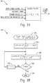
- Fig. 3Bdepicts a flowchart 320 illustrating example steps of a one dimensional (1D) moving sum method for computing mean and variance values with box windows of radius r.
- the mean and variance values with box windows of the radius rare calculated by applying a simple 1D moving sum method horizontally and vertically.
- the radius r parameteris received.
- a determination is made as to whether the variable k is greater than or equal to m. If the variable k is not greater than or equal to m, then the flowchart 320 proceeds to 330, where the variable k is incremented by 1 (kk + 1). After the variable k is incremented by 1 at 330, the flowchart 320 returns to 326. If it is determined at 328 that the variable k is greater than or equal to m, then the flowchart 320 is complete at 332.
- Fig. 3Cdepicts a box of pixels 340 with a window radius of two pixels.
- the window radius ris set equal to two pixels in order to limit the computational cost in the guided image filter 300. Therefore, for a pixel k 342, 5 x 5 neighboring pixels (as illustrated in the box 340 of Fig. 3C ) are used to calculate the variance ⁇ k 2 and the mean ⁇ k values. After calculating the variance ⁇ k 2 and the mean ⁇ k values, the a k and b k values are calculated according to Equations 2 and 3.
- the average of five a k and b k values shown in the dashed window 344are calculated to determine the a i and b i values in Equation 1. By making the calculations in this manner, only five line buffers are used.
- Fig. 3Ddepicts a flowchart 360 illustrating example steps performed by the guided filter 300.
- the variance ⁇ k 2 and the mean ⁇ k of the window ⁇ k of radius r centered at the pixel kare calculated.
- the coefficients a k and b kare calculated according to the Equations 2 and 3.
- the output of the guided image filteris calculated according to Equation 1.
- the guided image filter 300 of Fig. 3Ahas an edge-preserving property, and the edge-preserving property can be explained by considering two cases.
- a high activity areai.e., a high variance area
- the input imagechanges a relatively large amount within the window ⁇ k , such that ⁇ k 2 > > ⁇ . Therefore, for the high activity area, a k ⁇ 1 and b k ⁇ 0.
- a ⁇ 1 and b ⁇For a pixel within the high activity area, a ⁇ 1 and b ⁇ 0, such that the filtered pixel value remains relatively unchanged.
- the pixel valuesare almost constant in the window ⁇ k . Therefore, ⁇ k 2 > > ⁇ , and a k ⁇ 0 and b k ⁇ ⁇ k .
- a ⁇ 0 and b ⁇ ⁇For a pixel within the flat or smooth area, a ⁇ 0 and b ⁇ ⁇ , and the filtered pixel becomes the average of the neighboring pixels in the windows considered.
- the regularization parameter ⁇the range of edge or activity areas that are preserved is controlled. The ability to control the range of edge or activity areas that are preserved is desirable for detail enhancement in a television system because certain ranges of edges may be preserved for later processing after detail enhancement or for visual effects.
- the first signalis a filtered image generated by a guided image filter.
- Equation 1describes the output of the guided image filter, q i , which is an output corresponding to a single pixel i of an input image I.
- the first signalis an image that comprises a plurality of the q i values for each of the pixels of the input image I.
- the example detail signal 400includes information that is added to the input video signal to generate a detail-enhanced video signal.
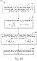
- Fig. 5Adepicts an example detail enhancement module 500 and corresponding inputs and outputs to the module 500.
- the variables "gain” and "noise” that are used in calculating the detail-enhanced video signal Eare selected to control how strongly details of the detail image D are added to the input image I (i.e., an intensity with which details of the detail image D are added to the input image I).
- Y detis selected to be equal to either E or I depending on whether the detail enhancement is performed at the Detail EE module 110 or at a later, downstream module.
- the detail enhancement module 500receives the coefficient a that is used in the guided image filter.
- the coefficient aprovides the module 500 with the activity level information, which is highly correlated to frequency information, for a small area where a current pixel of the input image I is located.
- the module 500is able to provide detail enhancement that varies based on the activity level (i.e., variance) within various regions of the input image I.
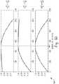
- Fig. 5Bdepicts exemplary gain functions 520 for use in the detail enhancement module 500.
- the exemplary gain functions 520depict three types of shapes that can be implemented by adjusting parameters of the detail enhancement module 500, where the degree of activity is the integer version of x in Equation 4 with a range of [0, 1024], mid is 500, and scale is 1.
- a top-most example gain function in Fig. 5B⁇ g 1 2 > ⁇ g 2 2 , such that the gain function has maximum values for lower degrees of activity, and the gain function has lower values for higher degrees of activity.
- ⁇ g 1 2⁇ ⁇ g 2 2 , such that the gain function has maximum values for higher degrees of activity, and the gain function has lower values for lower degrees of activity.
- ⁇ g 1 2⁇ g 2 2 , such that the gain function has a maximum value near the value of mid, and the gain function decreases as the activity level is increased or decreased.
- the input video image Iincludes low-variance portions, where the low-variance portions of the input video image I have a relatively low variance (i.e., level of activity).
- the input video image Ialso has high-variance portions, where the high-variance portions have a relatively high variance ( i.e., a relatively high level of activity).
- the gain functioncan be designed to include a distribution that causes the information from the detail signal to be added to the low-variance portions of the input video image I at a relatively high intensity.
- the gain functioncan also be designed such that the distribution causes the information from the detail signal to be added to the high-variance portions of the input video image I at a relatively low intensity.
- the distribution functionmay also be designed to function in an opposite manner (i.e., the distribution can be designed to cause the information from the detail signal to be added to the low-variance portions of the input video image I at a relatively low intensity, and to cause the information from the detail signal to be added to the high-variance portions of the input video image I at a relatively high intensity).
- the parameters mid, scale, ⁇ g 1 2 , and ⁇ g 2 2may be values that are set by users, or the parameters may be values that are set by software based on the characteristics of the video being displayed and users' enhancement requirements. In an example, default parameters are selected to cause mild enhancement.
- the scale parameter received by the detail enhancement module 500 and used in the Equation 4is the parameter that directly controls the intensity of the enhancement. In an example, the choice of the scale parameter is subjective and performed manually. In another example, a set of rules is provided to generate the scale parameter based on the characteristics of the video being displayed.
- the scale parameteris chosen to create not too much overshoot or saturation while maintaining strong enhancement. In certain examples, a number of saturated pixels from a current frame are collected, and the collected pixels are used to decrease or increase the scale parameter for a next frame. In an example, the scale parameter is set in firmware.
- the ⁇ g 1 2 and ⁇ g 2 2 parameters received by the detail enhancement module 500 and used in the Equation 4define the shape of the gain function.
- a default value of 128 for both of the ⁇ g 1 2 and ⁇ g 2 2 parameters with a in the range of (0, 1023)is used unless more concentrated or spread out enhancement is desired.
- the mid parameter received by the detail enhancement module 500 and used in the 4determines which range of edge or activity areas are to be enhanced the most. For example, if enhancement is desired for high activity or sharp edge areas, a large mid parameter is used. On the other hand, a small mid parameter is used for enhancement of relatively low activity areas. The default value of mid is 200 in the range of (0, 1023).
- the detail enhancement module 500is depicted as receiving parameters for filtering noise that are noise_num, noise_offset, and noise_cap.
- the enhancement scheme used by the detail enhancement module 500avoids enhancing noisy areas of the input image. In one example, a given level of noise is subtracted from all of the details of the detail image D. In another example, the noisy areas of the detail image D are detected and excluded from the enhancement. In the detail enhancement module 500 of Fig.
- linear transform parameters used in the Equation 1are utilized to control the noise level given the fact that noise in flat or smooth areas is more noticeable ( i.e., visible or distracting) than noise in high activity areas.
- a small value of aindicates a flat area, and a large value of a indicates a high activity area.
- Fig. 5Cdepicts a flowchart 530 illustrating example steps performed by the detail enhancement module 500.
- the detail image Dis calculated in the guided image filter ( e.g., as described above with reference to Figs. 3A - 3D ).
- the gain parameteris calculated using the parameter a according to Equation 4, where the parameter a was also used in the guided image filter.
- the noise parameteris calculated according to Equation 5.
- a human skin tone detectoris used in a system for generating a detail-enhanced video signal.
- enhancing the details in skin areas of an imageleads to an unnatural looking detail-enhanced image.
- a mild enhancement of the details in the skin areasis aesthetically pleasing. Therefore, it is desirable to detect skin areas and disable or enable the enhancement of these areas through individual controls that are realized by a different set of detail gain and noise parameters.
- an ICrCb color space based flesh tone detectoris implemented in the system for generating the detail-enhanced video signal.
- a HSV color space based flesh tone detectoris used with a single color space.
- the HSV based skin color detection schemeis integrated into a detail enhancement module, when a pixel is identified as skin color, a different set of detail gain and noise parameters are used. These parameters can be adjusted based on a viewer's preference.
- the detail enhancement modulee.g., including the skin tone detector or not including the skin tone detector
- all parametersare represented by integers, and the functions other than multiplication, addition, or shift are implemented by either table lookup or approximation methods.
- Fig. 6is a flowchart 600 illustrating example steps for calculating an enhanced output for an input image I.
- the mean and varianceare calculated for the window of radius r centered at the pixel k.
- the coefficients a_k and b_kare calculated based on Equations 2 and 3.
- the average values a i and b_i of all a_k and b_k in windows that cover the pixel iare calculated.
- the filtering output q_iis calculated based on the 1.
- Fig. 7is a flowchart 700 illustrating an example method for generating a detail-enhanced video signal.
- an input video signalis received.
- a first signal that is a linear transformation of the guidance signalis generated.
- a detail signalis generated by determining a difference between the input video signal and the first signal, where the detail signal includes information that is added to the input video signal to generate the detail-enhanced video signal.
- a filtered detail signalis generated by removing noise from the detail signal.
- the filtered detail signalis multiplied by a gain function to generate a second signal. The gain function is based on an amount of variance in the input video signal.
- the input video signal and the second signalare combined to generate the detail-enhanced video signal.
- the systems' and methods' datamay be stored and implemented in one or more different types of computer-implemented data stores, such as different types of storage devices and programming constructs (e.g., RAM, ROM, Flash memory, flat files, databases, programming data structures, programming variables, IF-THEN (or similar type) statement constructs, etc.).
- storage devices and programming constructse.g., RAM, ROM, Flash memory, flat files, databases, programming data structures, programming variables, IF-THEN (or similar type) statement constructs, etc.
- data structuresdescribe formats for use in organizing and storing data in databases, programs, memory, or other computer-readable media for use by a computer program.
- a module or processorincludes but is not limited to a unit of code that performs a software operation, and can be implemented for example as a subroutine unit of code, or as a software function unit of code, or as an object (as in an object-oriented paradigm), or as an applet, or in a computer script language, or as another type of computer code.
- the software components and/or functionalitymay be located on a single computer or distributed across multiple computers depending upon the situation at hand.
Landscapes
- Engineering & Computer Science (AREA)
- Multimedia (AREA)
- Signal Processing (AREA)
- Physics & Mathematics (AREA)
- General Physics & Mathematics (AREA)
- Theoretical Computer Science (AREA)
- Image Processing (AREA)
- Picture Signal Circuits (AREA)
Description
- The technology described in this document relates generally to the field of video processing and more particularly to image detail and edge enhancement.
- An edge enhancer comprising both fine detail enhancement (i.e., "Detail EE") and luminance transition improvement (LTI) is used to improve transitions in an input video signal. Applied in parallel, with Detail EE being applied on small transitions and with LTI being applied on large transitions, the output of the edge enhancer is the sum of the original signal (Yin), the detail enhancement (ΔYdet), and the transition improvement (ΔLTI). In example systems, Detail EE uses the principle of un-sharp masking and causes overshoot or ringing on edges that can enhance small details in the input video signal.
US 2010/295996 A1 discloses an image processing method that includes following steps: receiving an input video signal that includes information of a plurality of pixels, processing the input video signal to determine a color difference value of a target pixel of the pixels according to chromatic information of at least two pixels adjacent to the target pixel, generating a weighting signal which includes the weighting value of the target pixel according to the color difference value, and performing a sharpening operation on the input video signal according to weighting signal to generate a sharpened video signal. The weighting value is a monotonic decreasing function of the color difference value.US 2007/223834 A1 discloses that a SDR filter is used that can be a high-pass filter. SDR filters are designed to have circularly symmetric frequency response with different peak frequencies. In addition, the zero moment of SDR filter must be preserved, i.e. the summation of all filter coefficients must equal zero.- KAMING HE ET AL: "Guided Image Filtering", 5 September 2010, COMPUTER VISION - ECCV 2010, SPRINGER BERLIN HEIDELBERG, BERLIN, HEIDELBERG, PAGE(S) 1-14, disclose guided image filtering. Two examples of the kernel shapes in real images are shown. The guided filters kernel signs nearly zero weights to the pixels on the opposite side of the edge. The filter averages almost all the nearby pixels together and appears as low-pass filter.
- It is therefore the object of the present invention to provide an improved system for generating a detail-enhanced video signal, and a corresponding method.
- This object is solved by the subject matter of the independent claims.
- Preferred embodiments are defined by the dependent claims.
- The present disclosure is directed to systems and methods for generating a detail-enhanced video signal. An example system for generating a detail-enhanced video signal includes a filter that receives an input video signal. The filter is configured to generate a first signal that is a linear transformation of the input video signal and generate a detail signal. The detail signal is generated by determining a difference between the input video signal and the first signal, where the detail signal includes information that is added to the input video signal to generate the detail-enhanced video signal. The system also includes a noise reducer configured to generate a filtered detail signal by removing noise from the detail signal. The system also includes a multiplier configured to multiply the filtered detail signal by a gain function to generate a second signal. The gain function is based on an amount of variance in the input video signal. The system further includes an adder configured to combine the input video signal and the second signal to generate the detail-enhanced video signal.
- In another example, in a method for generating a detail-enhanced video signal, an input video signal is received. A first signal that is a linear transformation of the input video signal is generated. A detail signal is generated by determining a difference between the input video signal and the first signal, where the detail signal includes information that is added to the input video signal to generate the detail-enhanced video signal. A filtered detail signal is generated by removing noise from the detail signal. The filtered detail signal is multiplied by a gain function to generate a second signal. The gain function is based on an amount of variance in the input video signal. The input video signal and the second signal are combined to generate the detail-enhanced video signal.
Fig. 1 shows a block diagram of an example edge enhancement architecture.Fig. 2 depicts a block diagram of an example system for generating a detail-enhanced video signal.Fig. 3A depicts an example guided filter and corresponding inputs and outputs to the filter.Fig. 3B depicts a flowchart illustrating example steps of a one dimensional (ID) moving sum method for computing mean and variance values with box windows of radius r.Fig. 3C depicts a box of pixels with a window radius of two pixels.Fig. 3D depicts a flowchart illustrating example steps performed by the guided filter.Fig. 4 depicts an example detail signal (D) determined by taking a difference between an input video signal (I) and a first signal that is a linear transformation of a guidance signal (Q), such that D = I - Q.Fig. 5A depicts an example detail enhancement module and corresponding inputs and outputs to the module.Fig. 5B depicts exemplary gain functions for use in the detail enhancement module.Fig. 5C depicts a flowchart illustrating example steps performed by the detail enhancement module.Fig. 6 is a flowchart illustrating example steps for calculating an enhanced output for an input image I.Fig. 7 is a flowchart illustrating an example method for generating a detail-enhanced video signal.Fig. 1 shows a block diagram 100 of an example edge enhancement architecture, where the example edge enhancement architecture is employed in a video post processing (VPP) system. InFig. 1 , avideo signal Y in 102 is input into the edge enhancement architecture that includes both a fine detail enhancement ("Detail EE")module 110 and a luminance transition improvement ("LTI")module 140. Thevideo signal Y in 102 is first input into theDetail EE module 110, and theDetail EE module 110 outputs adetail signal ΔY det 107 that represents enhanced fine details of thevideo signal Y in 102. Thedetail signal ΔY det 107 is up-scaled atdetail scaler 130 to generatesignal ΔY det-scl 104.- Another output of the
Detail EE module 110 isY det 101. In the example ofFig. 1 ,Y det 101 comprises the inputvideo signal Y in 102 passed through theDetail EE module 110 without adjustment. In another example,Y det 101 comprises thedetail signal ΔY det 107 added to inputvideo signal Y in 102 to create a video signal with fine details enhanced.Y det 101 is up-scaled invideo scaler 120 to generate a scaledsignal Y scl 103, and the scaledsignal Y scl 103 is input into theLTI module 140. In the example ofFig. 1 , thevideo scaler 120 and thedetail scaler 130 include filters that comprise the same scaler filters. In another example, thevideo scaler 120 and thedetail scaler 130 include filters that comprise different scaler filters. The scaledsignal Y scl 103 plus an LTI improvement signal ΔLTI is theoutput 105 of theLTI module 140. The output signal Yscl +ΔLTI 105 is added to the scaled detail enhancedsignal ΔY det-scl 104 in the spatial domain atadder 160. The final output of the edge enhancement architecture,Y ee-out 106, is the edge-enhanced and scaled signal. - As illustrated in
Fig. 1 , the example detail enhancement architecture includes two independent modules, a luma (Y) detail enhancement module (i.e., comprising the Detail EE module 110) and a transient improvement module (i.e., comprising the LTI module 140). The transient improvement module is used for enhancing large edges of the inputvideo signal Y in 102, while the luma detail enhancement module is used to enhance fine edges of the inputvideo signal Y in 102.Figures 2 - 7 and their corresponding description herein are directed to aspects of detail enhancement that are performed in theDetail EE module 110. As described in further detail below, the detail enhancement performed in theDetail EE module 110 utilizes a guided image filter for extracting details from an input image. By contrast, alternative detail enhancement methods do not use a guided image filter and instead use fixed parameters in either high-pass or bandpass filters to extract details from the input image. Such alternative detail enhancement methods result in large details around edges and few details in dark or relatively smooth regions of the inputvideo signal Y in 102. In the alternative detail enhancement methods, with a strong enhancement gain, overshoot or temporal flicker is often observed around edges, while the details in the dark regions are still not efficiently enhanced. As detailed below, with reference toFigs. 2 - 7 , theDetail EE module 110 utilizing the guided image filter may overcome the deficiencies inherent in the alternative detail enhancement methods. Fig. 2 depicts a block diagram 200 of an example system for generating a detail-enhancedvideo signal 220. In the example system ofFig. 2 , a guidedimage filter 202 receives an input video signal (I) 204 and aguidance signal 206. Theinput video signal 204 includes one or more images, and the example system is configured to add details to the one or more images to generate the detail-enhancedvideo signal 220. In an example, the one or more images of theinput video signal 204 include video frames. Theguidance signal 206 similarly includes one or more images, and the content of theguidance signal 206 may be considered by the guidedimage filter 202 in performing a filtering operation. In an example system, theguidance signal 206 is used in enforcing constraints on the guidedimage filter 202, and in another example system, filter kernels are built using theguidance signal 206. In an example, theguidance signal 206 is theinput video signal 204, such that the twoseparate signals image filter 202, and a single signal representing both of thesignals filter 202.- The guided
image filter 202 is configured to generate a first signal (Q) that is a linear transformation of theguidance signal 206. As described in further detail below, with reference toFigs. 3A - 3D , the linear transformation involves determining average mean and variance values for a plurality of windows of radiusr that cover a pixel of theguidance signal 206. Using the first signal and theinput video signal 204, the guidedimage filter 202 generates a detail signal (D) 208. Thedetail signal 208 is determined by taking a difference between theinput video signal 204 and the first signal, such that thedetail signal 208 is equal to I - Q. Thedetail signal 208 includes information that is added to theinput video signal 204 to generate the detail-enhancedvideo signal 220, as described in further detail below. - The system of
Fig. 2 further includes anoise reducer 210 configured to generate a filtereddetail signal 212 by removing noise from thedetail signal 208. Amultiplier 214 receives the filtereddetail signal 212 and multiplies the filtereddetail signal 212 by a gain function to generate asecond signal 216. The gain function is based on an amount of variance in theinput video signal 204, where the variance is indicative of an activity level or an amount of change within theinput video signal 204. Anadder 218 receives theinput video signal 204 and thesecond signal 216. Theadder 218 is configured to combine theinput video signal 204 and thesecond signal 2 16 to generate the detail-enhancedvideo signal 220. - In an example, the
input video signal 204, theguidance signal 206, thedetail signal 208, the filtereddetail signal 212, and thesecond signal 216 each comprise a plurality of pixels. In an example, the plurality of pixels is a particular frame of a video signal. Further, as described in greater detail below, themultiplier 214 is configured to multiply a pixel of the plurality of pixels included in the filtereddetail signal 212 by a gain value of the gain function. The gain value is based on a variance of a group of pixels, where the group of pixels includes a pixel of the plurality of pixels included in theinput video signal 204. The pixel of the plurality of pixels included in the filtereddetail signal 212 and the pixel of the plurality of pixels included in theinput video signal 204 have same x-y coordinates, such that the pixels used are corresponding pixels in the different images. Fig. 3A depicts an example guidedfilter 300 and corresponding inputs and outputs to thefilter 300. The guidedfilter 300 receives the inputs including an input video signal containing an input image (I) to be filtered, a guidance image, a window radius (r), and a regularization parameter (ε). In the example ofFig. 3A , where the guidedfilter 300 is used to perform a detail enhancement procedure, the guidance image and the input image are the same. Using the input image (I) to be filtered, the guidedfilter 300 calculates a filtering outputqi for every pixel i ∈ I using the following linear transformation:


Fig. 3B depicts aflowchart 320 illustrating example steps of a one dimensional (1D) moving sum method for computing mean and variance values with box windows of radius r. The mean and variance values with box windows of the radius r are calculated by applying a simple 1D moving sum method horizontally and vertically. At 322, an input signal p_i is received, where i = 0, ... , m. Additionally, at 322, the radius r parameter is received. At 324, a value of s_0 is determined, where s_0 = sum of (p_0, ... , p_r). Further, at 324, a variable k is set equal to 1 (k = 1). At 326, a value s k is determined, where s_k = s_(k-1) + p_(i + r) - p_(i-r - 1). Additionally, at 326, p_j is set to 0 if j < 0. At 328, a determination is made as to whether the variable k is greater than or equal to m. If the variable k is not greater than or equal to m, then theflowchart 320 proceeds to 330, where the variable k is incremented by 1 (k = k + 1). After the variable k is incremented by 1 at 330, theflowchart 320 returns to 326. If it is determined at 328 that the variable k is greater than or equal to m, then theflowchart 320 is complete at 332.Fig. 3C depicts a box ofpixels 340 with a window radius of two pixels. In an example, in the calculating ofa i andb i inEquation 1, the window radius r is set equal to two pixels in order to limit the computational cost in the guidedimage filter 300. Therefore, for apixel k 342, 5 x 5 neighboring pixels (as illustrated in thebox 340 ofFig. 3C ) are used to calculate thevariance 
variance 
Equations window 344 are calculated to determine thea i andb i values inEquation 1. By making the calculations in this manner, only five line buffers are used.Fig. 3D depicts aflowchart 360 illustrating example steps performed by the guidedfilter 300. At 362, for each pixel k in the input video signal (I), thevariance 
Equations a i andb i of allak andbk in windows that cover the pixel i are calculated according to

Equation 1.- The guided
image filter 300 ofFig. 3A has an edge-preserving property, and the edge-preserving property can be explained by considering two cases. First, for a high activity area (i.e., a high variance area), the input image changes a relatively large amount within the windowωk, such that
a ≈ 1 andb ≈ 0, such that the filtered pixel value remains relatively unchanged. - On the other hand, for a flat or smooth area, the pixel values are almost constant in the windowωk. Therefore,

a ≈ 0 andb ≈µ , and the filtered pixel becomes the average of the neighboring pixels in the windows considered. By adjusting the regularization parameter ε, the range of edge or activity areas that are preserved is controlled. The ability to control the range of edge or activity areas that are preserved is desirable for detail enhancement in a television system because certain ranges of edges may be preserved for later processing after detail enhancement or for visual effects. Fig. 4 depicts an example detail signal (D) 400 determined by taking a difference between an input video signal (I) and a first signal (Q) that is a linear transformation of a guidance signal, such that D = I - Q. As explained above, with reference toFigs. 3A - 3D , the first signal is a filtered image generated by a guided image filter. For example,Equation 1 describes the output of the guided image filter,qi, which is an output corresponding to a single pixel i of an input image I. The first signal is an image that comprises a plurality of theqi values for each of the pixels of the input image I. Theexample detail signal 400 includes information that is added to the input video signal to generate a detail-enhanced video signal.Fig. 5A depicts an exampledetail enhancement module 500 and corresponding inputs and outputs to themodule 500. As described above, a detail image D = I - Q is generated by a guided image filter, where I is an input image and Q is an output of the guided image filter that is obtained by taking a linear transformation of a guidance image.Fig. 5A depicts the input image I and the detail image D = I - Q being received by thedetail enhancement module 500. Based on these inputs and others described below, thedetail enhancement module 500 generates a detail-enhanced video signal E according to E = I + (D - noise)*gain. The variables "gain" and "noise" that are used in calculating the detail-enhanced video signal E are selected to control how strongly details of the detail image D are added to the input image I (i.e., an intensity with which details of the detail image D are added to the input image I). With reference toFig. 1 , the detail image ΔYdet = (D - noise)*gain, and Ydet = E or I. Ydet is selected to be equal to either E or I depending on whether the detail enhancement is performed at theDetail EE module 110 or at a later, downstream module.- The "gain" function used in determining the detail-enhanced video signal E according to E = I + (D - noise)*gain allows the
module 500 to provide detail enhancement that varies based on the activity level (i.e., variance) within various regions of the input image I. As illustrated inFig. 5A , thedetail enhancement module 500 receives the coefficienta that is used in the guided image filter. The coefficienta provides themodule 500 with the activity level information, which is highly correlated to frequency information, for a small area where a current pixel of the input image I is located. An expression for the gain function is
a for the current pixel, andscale, mid,

detail enhancement module 500 that control a Gaussian distribution shape of the gain function. By controlling the Gaussian distribution shape of the gain function using the variablesa , scale, mid,

module 500 is able to provide detail enhancement that varies based on the activity level(i.e., variance) within various regions of the input image I. Fig. 5B depicts exemplary gain functions 520 for use in thedetail enhancement module 500. The exemplary gain functions 520 depict three types of shapes that can be implemented by adjusting parameters of thedetail enhancement module 500, where the degree of activity is the integer version ofx in Equation 4 with a range of [0, 1024],mid is 500, andscale is 1. In a top-most example gain function inFig. 5B ,
Fig. 5B ,
Fig. 5B ,
- In an example, the input video image I includes low-variance portions, where the low-variance portions of the input video image I have a relatively low variance (i.e., level of activity). The input video image I also has high-variance portions, where the high-variance portions have a relatively high variance (i.e., a relatively high level of activity). As depicted in the top-most gain function of
Fig. 5B , the gain function can be designed to include a distribution that causes the information from the detail signal to be added to the low-variance portions of the input video image I at a relatively high intensity. As is further depicted in the top-most gain function ofFig. 5B , the gain function can also be designed such that the distribution causes the information from the detail signal to be added to the high-variance portions of the input video image I at a relatively low intensity. As depicted in the middle example gain function ofFig. 5B , the distribution function may also be designed to function in an opposite manner (i.e., the distribution can be designed to cause the information from the detail signal to be added to the low-variance portions of the input video image I at a relatively low intensity, and to cause the information from the detail signal to be added to the high-variance portions of the input video image I at a relatively high intensity). - In the Equation 4, the parametersmid, scale,


detail enhancement module 500 and used in the Equation 4 is the parameter that directly controls the intensity of the enhancement. In an example, the choice of thescale parameter is subjective and performed manually. In another example, a set of rules is provided to generate thescale parameter based on the characteristics of the video being displayed. Thescale parameter is chosen to create not too much overshoot or saturation while maintaining strong enhancement. In certain examples, a number of saturated pixels from a current frame are collected, and the collected pixels are used to decrease or increase thescale parameter for a next frame. In an example, thescale parameter is set in firmware. - The


detail enhancement module 500 and used in the Equation 4 define the shape of the gain function. The larger the


a in the range of (0, 1023) is used unless more concentrated or spread out enhancement is desired. - Themid parameter received by the
detail enhancement module 500 and used in the 4 determines which range of edge or activity areas are to be enhanced the most. For example, if enhancement is desired for high activity or sharp edge areas, a largemid parameter is used. On the other hand, a smallmid parameter is used for enhancement of relatively low activity areas. The default value ofmid is 200 in the range of (0, 1023). - With reference again to
Fig. 5A , thedetail enhancement module 500 is depicted as receiving parameters for filtering noise that are noise_num, noise_offset, and noise_cap. The parameters noise_num, noise_offset, and noise_cap are used to determine the "noise" variable included in the equation E = I + (D - noise)*gain that is used by thedetail enhancement module 500. If noisy areas of the input image are enhanced, the output image appears grainy and unpleasant. The enhancement scheme used by thedetail enhancement module 500 avoids enhancing noisy areas of the input image. In one example, a given level of noise is subtracted from all of the details of the detail image D. In another example, the noisy areas of the detail image D are detected and excluded from the enhancement. In thedetail enhancement module 500 ofFig. 5A , linear transform parameters used in theEquation 1 are utilized to control the noise level given the fact that noise in flat or smooth areas is more noticeable (i.e., visible or distracting) than noise in high activity areas. A small value ofa indicates a flat area, and a large value ofa indicates a high activity area. The noise level for each pixel is determined according to
where noise num, noise offset, and noise cap are parameters received by thedetail enhancement module 500 that can be set via registers. Fig. 5C depicts aflowchart 530 illustrating example steps performed by thedetail enhancement module 500. At 532, the detail image D is calculated according to D = I - Q. In other examples, the detail image D is calculated in the guided image filter (e.g., as described above with reference toFigs. 3A - 3D ). At 534, the gain parameter is calculated using the parametera according to Equation 4, where the parametera was also used in the guided image filter. At 536, the noise parameter is calculated according to Equation 5. At 538, the detail-enhanced video image E is calculated according to E = I + (D - noise)*gain.- In an example, a human skin tone detector is used in a system for generating a detail-enhanced video signal. In one example, enhancing the details in skin areas of an image leads to an unnatural looking detail-enhanced image. In other examples, a mild enhancement of the details in the skin areas is aesthetically pleasing. Therefore, it is desirable to detect skin areas and disable or enable the enhancement of these areas through individual controls that are realized by a different set of detail gain and noise parameters.
- In an example, an ICrCb color space based flesh tone detector is implemented in the system for generating the detail-enhanced video signal. In another example, a HSV color space based flesh tone detector is used with a single color space. In the another example, where the HSV based skin color detection scheme is integrated into a detail enhancement module, when a pixel is identified as skin color, a different set of detail gain and noise parameters are used. These parameters can be adjusted based on a viewer's preference. A conversion from RGB to HSV is determined according to


- In implementing the detail enhancement module (e.g., including the skin tone detector or not including the skin tone detector), all parameters are represented by integers, and the functions other than multiplication, addition, or shift are implemented by either table lookup or approximation methods.
Fig. 6 is aflowchart 600 illustrating example steps for calculating an enhanced output for an input image I. At 602, for each pixel k in an input image I, the mean and variance are calculated for the window of radius r centered at the pixel k. Further, at 602, the coefficients a_k and b_k are calculated based onEquations Fig. 7 is aflowchart 700 illustrating an example method for generating a detail-enhanced video signal. At 702, an input video signal is received. At 704, a first signal that is a linear transformation of the guidance signal is generated. At 706, a detail signal is generated by determining a difference between the input video signal and the first signal, where the detail signal includes information that is added to the input video signal to generate the detail-enhanced video signal. At 708, a filtered detail signal is generated by removing noise from the detail signal. At 710, the filtered detail signal is multiplied by a gain function to generate a second signal. The gain function is based on an amount of variance in the input video signal. At 712, the input video signal and the second signal are combined to generate the detail-enhanced video signal.- This written description uses examples to disclose the invention, including the best mode, and also to enable a person skilled in the art to make and use the invention. The patentable scope of the invention may include other examples. Additionally, the methods and systems described herein may be implemented on many different types of processing devices by program code comprising program instructions that are executable by the device processing subsystem. The software program instructions may include source code, object code, machine code, or any other stored data that is operable to cause a processing system to perform the methods and operations described herein. Other implementations may also be used, however, such as firmware or even appropriately designed hardware configured to carry out the methods and systems described herein.
- The systems' and methods' data (e.g., associations, mappings, data input, data output, intermediate data results, final data results, etc.) may be stored and implemented in one or more different types of computer-implemented data stores, such as different types of storage devices and programming constructs (e.g., RAM, ROM, Flash memory, flat files, databases, programming data structures, programming variables, IF-THEN (or similar type) statement constructs, etc.). It is noted that data structures describe formats for use in organizing and storing data in databases, programs, memory, or other computer-readable media for use by a computer program.
- The computer components, software modules, functions, data stores and data structures described herein may be connected directly or indirectly to each other in order to allow the flow of data needed for their operations. It is also noted that a module or processor includes but is not limited to a unit of code that performs a software operation, and can be implemented for example as a subroutine unit of code, or as a software function unit of code, or as an object (as in an object-oriented paradigm), or as an applet, or in a computer script language, or as another type of computer code. The software components and/or functionality may be located on a single computer or distributed across multiple computers depending upon the situation at hand.
- It should be understood that as used in the description herein and throughout the claims that follow, the meaning of "a," "an," and "the" includes plural reference unless the context clearly dictates otherwise. Also, as used in the description herein and throughout the claims that follow, the meaning of "in" includes "in" and "on" unless the context clearly dictates otherwise. Further, as used in the description herein and throughout the claims that follow, the meaning of "each" does not require "each and every" unless the context clearly dictates otherwise. Finally, as used in the description herein and throughout the claims that follow, the meanings of "and" and "or" include both the conjunctive and disjunctive and may be used interchangeably unless the context expressly dictates otherwise; the phrase "exclusive of" may be used to indicate situations where only the disjunctive meaning may apply.


Claims (11)
- A system (200) for generating a detail-enhanced video signal (220), the system comprising:a filter (202, 300) that receives an input video signal (204), the filter being configured to:generate a first signal that is a linear transformation of the input video signal,wherein the linear transformation includes determining average mean values and average variance values for a plurality of windows that cover a pixel of the input video signal, andgenerate a detail signal (208, 400) by determining a difference between the input video signal and the first signal;a noise reducer (210) configured to generate a filtered detail signal (212) by removing noise from the detail signal, wherein parameters of the linear transformation are utilized to control the noise;a multiplier (214) configured to multiply the filtered detail signal by a gain function (520) to generate a second signal (216), the gain function being based on an amount of variance in the input video signal, such that (i) the gain function peaks near a mid value of variance, (ii) from the mid value the gain function decreases with increasing variance, and (iii) from the mid value the gain function decreases with decreasing variance; andan adder (218) configured to combine the input video signal and the second signal to generate the detail-enhanced video signal.
- The system (200) of claim 1,
wherein the input video signal (204) comprises a first plurality of pixels;
wherein the filtered detail signal (212) comprises a second plurality of pixels;
wherein the multiplier (214) is configured to multiply a pixel of the second plurality of pixels and a gain value of the gain function (520);
wherein the gain value is based on a variance of a group of pixels that includes a pixel of the first plurality of pixels; and
wherein the pixel of the first plurality of pixels and the pixel of the second plurality of pixels have same x-y coordinates. - The system (200) of claim 1,
wherein the input video signal (204) includes low-variance portions;
wherein the input video signal includes high-variance portions; and
wherein the gain function (520) includes a distribution that causes information from the detail signal (208, 400) to be added to the low-variance portions at a higher intensity than the information from the detail signal is added to the high-variance portions. - The system (200) of claim 1,
wherein the input video (204) signal includes low-variance portions;
wherein the input video signal includes high-variance portions; and
wherein the gain function (520) includes a distribution that causes information from the detail signal (208, 400) to be added to the high-variance portions at a higher intensity than the information from the detail signal is added to the low-variance portions. - The system (200) of claim 1, wherein the second signal (216) is defined by

- The system (200) of claim 1, wherein the linear transformation is defined by

a i is an average variance value of a group of pixels including the pixeli, andb i is an average mean value of the group of pixels. - The system (200) of claim 6, wherein the gain function (520) is based on the average variance value
a i. - The system (200) of claim 6, wherein the gain function (520) is defined by
 wheregain is a value of the gain function at a particular value of
a i, andmid,


 wherein |ω| is a number of the windows used in determining the average variance value, wherein for a windowωk centered at a pixelk

- The system (200) of claim 6, wherein the noise reducer (210) utilizes an equation for calculating the noise in the detail signal (208, 400), and wherein the equation is based on the average variance value
a i, wherein the noise is calculated based onnoise_num divided by the average variance valuea i plusnoise_offset, wherein the parametersnoise_num andnoise_offset are set, wherein


- The system (200) of claim 1, further arranged for:
determining a noise value for a pixel of the detail signal (208, 400), wherein the noise value is based on a variance of a group of pixels including a pixel of the input video signal (204), and wherein the pixel of the detail signal and the pixel of the input video signal have same x-y coordinates. - A method (700) for generating a detail-enhanced video signal (220), the method comprising:receiving (702) an input video signal (204);generating (704) a first signal that is a linear transformation of the input video signal,wherein the linear transformation includes determining average mean values and average variance values for a plurality of windows that cover a pixel of the input video signal;generating (706) a detail signal (208, 400) by determining a difference between the input video signal and the first signal;generating (708) a filtered detail signal (212) by removing noise from the detail signal, wherein parameters of the linear transformation are utilized to control the noise;multiplying (710) the filtered detail signal by a gain function (520) to generate a second signal (216), the gain function being based on an amount of variance in the input video signal, such that (i) the gain function peaks near a mid value of variance, (ii) from the mid value the gain function decreases with increasing variance, and (iii) from the mid value the gain function decreases with decreasing variance; andcombining (712) the input video signal and the second signal to generate the detail-enhanced video signal.


Applications Claiming Priority (2)
| Application Number | Priority Date | Filing Date | Title |
|---|---|---|---|
| US201361804522P | 2013-03-22 | 2013-03-22 | |
| PCT/US2014/031311WO2014153450A2 (en) | 2013-03-22 | 2014-03-20 | Guided filter-based detail enhancement |
Publications (3)
| Publication Number | Publication Date |
|---|---|
| EP2976877A2 EP2976877A2 (en) | 2016-01-27 |
| EP2976877A4 EP2976877A4 (en) | 2016-11-30 |
| EP2976877B1true EP2976877B1 (en) | 2020-01-08 |
Family
ID=51568897
Family Applications (1)
| Application Number | Title | Priority Date | Filing Date |
|---|---|---|---|
| EP14769741.1AActiveEP2976877B1 (en) | 2013-03-22 | 2014-03-20 | Guided filter-based detail enhancement |
Country Status (7)
| Country | Link |
|---|---|
| US (1) | US9241093B2 (en) |
| EP (1) | EP2976877B1 (en) |
| JP (1) | JP6587317B2 (en) |
| KR (1) | KR101760854B1 (en) |
| CN (1) | CN105191277B (en) |
| TW (1) | TW201447816A (en) |
| WO (1) | WO2014153450A2 (en) |
Families Citing this family (8)
| Publication number | Priority date | Publication date | Assignee | Title |
|---|---|---|---|---|
| EP2808841A1 (en)* | 2013-05-31 | 2014-12-03 | Thomson Licensing | Method and apparatus for generating a noise profile of noise in an image sequence |
| LU92688B1 (en)* | 2015-04-01 | 2016-10-03 | Iee Int Electronics & Eng Sa | Method and system for real-time motion artifact handling and noise removal for tof sensor images |
| WO2017104291A1 (en)* | 2015-12-18 | 2017-06-22 | 三菱電機株式会社 | Image processing device and image processing method |
| US10403006B2 (en) | 2016-08-26 | 2019-09-03 | General Electric Company | Guided filter for multiple level energy computed tomography (CT) |
| CN109906610B (en)* | 2016-11-04 | 2020-06-05 | 谷歌有限责任公司 | Recovery of video coding using filtering and subspace projection |
| CN107833232B (en)* | 2017-10-27 | 2020-10-09 | 智车优行科技(北京)有限公司 | Image detail extraction method and device, electronic equipment and computer storage medium |
| CN108335275B (en)* | 2018-02-13 | 2019-12-13 | 腾讯科技(深圳)有限公司 | Image enhancement method and device, computing equipment and storage medium |
| CN116548928B (en)* | 2023-07-11 | 2023-09-08 | 西安浩阳志德医疗科技有限公司 | An Internet-based nursing service system |
Family Cites Families (21)
| Publication number | Priority date | Publication date | Assignee | Title |
|---|---|---|---|---|
| JPH03502975A (en)* | 1988-12-27 | 1991-07-04 | イーストマン・コダック・カンパニー | Blur masking using center-weighted local variance for image sharpening and noise suppression |
| US5799111A (en)* | 1991-06-14 | 1998-08-25 | D.V.P. Technologies, Ltd. | Apparatus and methods for smoothing images |
| JPH10210297A (en)* | 1997-01-20 | 1998-08-07 | Dainippon Screen Mfg Co Ltd | Image processor |
| JPH10243239A (en)* | 1997-02-28 | 1998-09-11 | Fuji Photo Film Co Ltd | Image-processing method for noise suppression and sharpness emphasis for digital image |
| US6847737B1 (en)* | 1998-03-13 | 2005-01-25 | University Of Houston System | Methods for performing DAF data filtering and padding |
| JP2002033942A (en)* | 2000-07-17 | 2002-01-31 | Sanyo Electric Co Ltd | Method for suppressing noise in image signal, and image signal processor using the noise-suppressing method |
| KR100327385B1 (en)* | 2000-07-18 | 2002-03-13 | Lg Electronics Inc | Spatio-temporal three-dimensional noise filter |
| US6832000B2 (en)* | 2001-03-28 | 2004-12-14 | Koninklijke Philips Electronics N.V. | Automatic segmentation-based grass detection for real-time video |
| EP1387317A4 (en)* | 2001-04-19 | 2008-10-15 | Toshiba Kk | IMAGE PROCESSING METHOD AND DEVICE |
| KR100624421B1 (en)* | 2004-05-04 | 2006-09-19 | 삼성전자주식회사 | Digital video signal filtering device and method |
| US20060056722A1 (en)* | 2004-09-14 | 2006-03-16 | Nathan Moroney | Edge preserving method and apparatus for image processing |
| EP1681849B1 (en)* | 2005-01-18 | 2011-10-19 | LG Electronics, Inc. | Apparatus for removing noise from a video signal |
| US20070223834A1 (en)* | 2006-03-23 | 2007-09-27 | Samsung Electronics Co., Ltd. | Method for small detail restoration in digital images |
| KR20070116738A (en)* | 2006-06-06 | 2007-12-11 | 소니 가부시끼 가이샤 | Video signal processing method, program of video signal processing method, recording medium recording program of video signal processing method and video signal processing apparatus |
| TWI361618B (en)* | 2006-12-26 | 2012-04-01 | Realtek Semiconductor Corp | Method and device for estimating noise |
| JP5095860B2 (en)* | 2008-06-19 | 2012-12-12 | マーベル ワールド トレード リミテッド | Isolated edge enhancement architecture |
| JP5223702B2 (en)* | 2008-07-29 | 2013-06-26 | 株式会社リコー | Image processing apparatus, noise reduction method, program, and storage medium |
| US8570386B2 (en)* | 2008-12-31 | 2013-10-29 | Stmicroelectronics S.R.L. | Method of merging images and relative method of generating an output image of enhanced quality |
| TWI387313B (en)* | 2009-05-21 | 2013-02-21 | Novatek Microelectronics Corp | Circuit and method for image processing |
| US8279345B2 (en)* | 2009-07-21 | 2012-10-02 | Qualcomm Incorporated | System and method for random noise estimation in a sequence of images |
| US8358691B1 (en)* | 2009-10-30 | 2013-01-22 | Adobe Systems Incorporated | Methods and apparatus for chatter reduction in video object segmentation using a variable bandwidth search region |
- 2014
- 2014-03-20EPEP14769741.1Apatent/EP2976877B1/enactiveActive
- 2014-03-20KRKR1020157030412Apatent/KR101760854B1/enactiveActive
- 2014-03-20JPJP2016504359Apatent/JP6587317B2/enactiveActive
- 2014-03-20WOPCT/US2014/031311patent/WO2014153450A2/enactiveApplication Filing
- 2014-03-20USUS14/220,528patent/US9241093B2/enactiveActive
- 2014-03-20CNCN201480017260.8Apatent/CN105191277B/enactiveActive
- 2014-03-21TWTW103110729Apatent/TW201447816A/enunknown
Non-Patent Citations (1)
| Title |
|---|
| None* |
Also Published As
| Publication number | Publication date |
|---|---|
| US9241093B2 (en) | 2016-01-19 |
| KR20150132878A (en) | 2015-11-26 |
| EP2976877A4 (en) | 2016-11-30 |
| JP6587317B2 (en) | 2019-10-09 |
| CN105191277B (en) | 2019-03-08 |
| TW201447816A (en) | 2014-12-16 |
| KR101760854B1 (en) | 2017-07-24 |
| US20140285719A1 (en) | 2014-09-25 |
| WO2014153450A3 (en) | 2015-11-19 |
| CN105191277A (en) | 2015-12-23 |
| JP2016517975A (en) | 2016-06-20 |
| EP2976877A2 (en) | 2016-01-27 |
| WO2014153450A2 (en) | 2014-09-25 |
Similar Documents
| Publication | Publication Date | Title |
|---|---|---|
| EP2976877B1 (en) | Guided filter-based detail enhancement | |
| Deng | A generalized unsharp masking algorithm | |
| US8050509B2 (en) | Method of and apparatus for eliminating image noise | |
| US10672112B2 (en) | Method and system for real-time noise removal and image enhancement of high-dynamic range images | |
| US7529425B2 (en) | Denoising method, apparatus, and program | |
| CN101460975B (en) | Optical imaging systems and methods utilizing nonlinear and/or spatially varying image processing | |
| JP4460839B2 (en) | Digital image sharpening device | |
| Tsai | Adaptive local power-law transformation for color image enhancement | |
| US20040042676A1 (en) | Method and apparatus for illumination compensation of digital images | |
| JP4456819B2 (en) | Digital image sharpening device | |
| EP2355039B1 (en) | Image generating apparatus and method for emphasizing edge based on image characteristics | |
| Park et al. | Low-light image restoration using bright channel prior-based variational Retinex model | |
| US9299149B2 (en) | Image enhancement using modulation strength map and modulation kernel | |
| Vazquez-Corral et al. | A fast image dehazing method that does not introduce color artifacts | |
| Vijay et al. | A simple and enhanced low-light image enhancement process using effective illumination mapping approach | |
| US20060013503A1 (en) | Methods of preventing noise boost in image contrast enhancement | |
| US20090185757A1 (en) | Apparatus and method for immersion generation | |
| Wang et al. | Image enhancement | |
| Lee et al. | Motion deblurring using edge map with blurred/noisy image pairs | |
| US7024036B2 (en) | Image processing apparatus, image processing method, storage medium, and program | |
| Martens | Adaptive contrast enhancement through residue-image processing | |
| CN115311243B (en) | Image sharpening method and terminal based on filter difference | |
| Singh et al. | Image enhancement by adaptive power-law transformations | |
| RU2680754C2 (en) | Method of increasing the sharpness of digital image | |
| Sridhar et al. | A generalised unsharp masking algorithm using bilateral filter |
Legal Events
| Date | Code | Title | Description |
|---|---|---|---|
| PUAI | Public reference made under article 153(3) epc to a published international application that has entered the european phase | Free format text:ORIGINAL CODE: 0009012 | |
| 17P | Request for examination filed | Effective date:20150921 | |
| AK | Designated contracting states | Kind code of ref document:A2 Designated state(s):AL AT BE BG CH CY CZ DE DK EE ES FI FR GB GR HR HU IE IS IT LI LT LU LV MC MK MT NL NO PL PT RO RS SE SI SK SM TR | |
| AX | Request for extension of the european patent | Extension state:BA ME | |
| DAX | Request for extension of the european patent (deleted) | ||
| REG | Reference to a national code | Ref country code:DE Ref legal event code:R079 Ref document number:602014059702 Country of ref document:DE Free format text:PREVIOUS MAIN CLASS: H04N0005000000 Ipc:H04N0005210000 | |
| A4 | Supplementary search report drawn up and despatched | Effective date:20161102 | |
| RIC1 | Information provided on ipc code assigned before grant | Ipc:H04N 5/14 20060101ALI20161026BHEP Ipc:H04N 5/208 20060101ALI20161026BHEP Ipc:H04N 5/21 20060101AFI20161026BHEP | |
| STAA | Information on the status of an ep patent application or granted ep patent | Free format text:STATUS: EXAMINATION IS IN PROGRESS | |
| 17Q | First examination report despatched | Effective date:20180104 | |
| RAP1 | Party data changed (applicant data changed or rights of an application transferred) | Owner name:MARVELL INTERNATIONAL LTD. | |
| RAP1 | Party data changed (applicant data changed or rights of an application transferred) | Owner name:SYNAPTICS LLC Owner name:SYNAPTICS INCORPORATED | |
| GRAP | Despatch of communication of intention to grant a patent | Free format text:ORIGINAL CODE: EPIDOSNIGR1 | |
| STAA | Information on the status of an ep patent application or granted ep patent | Free format text:STATUS: GRANT OF PATENT IS INTENDED | |
| INTG | Intention to grant announced | Effective date:20190725 | |
| GRAS | Grant fee paid | Free format text:ORIGINAL CODE: EPIDOSNIGR3 | |
| GRAA | (expected) grant | Free format text:ORIGINAL CODE: 0009210 | |
| STAA | Information on the status of an ep patent application or granted ep patent | Free format text:STATUS: THE PATENT HAS BEEN GRANTED | |
| AK | Designated contracting states | Kind code of ref document:B1 Designated state(s):AL AT BE BG CH CY CZ DE DK EE ES FI FR GB GR HR HU IE IS IT LI LT LU LV MC MK MT NL NO PL PT RO RS SE SI SK SM TR | |
| REG | Reference to a national code | Ref country code:GB Ref legal event code:FG4D | |
| REG | Reference to a national code | Ref country code:CH Ref legal event code:EP | |
| REG | Reference to a national code | Ref country code:DE Ref legal event code:R096 Ref document number:602014059702 Country of ref document:DE | |
| REG | Reference to a national code | Ref country code:IE Ref legal event code:FG4D | |
| REG | Reference to a national code | Ref country code:AT Ref legal event code:REF Ref document number:1224143 Country of ref document:AT Kind code of ref document:T Effective date:20200215 | |
| REG | Reference to a national code | Ref country code:NL Ref legal event code:MP Effective date:20200108 | |
| REG | Reference to a national code | Ref country code:LT Ref legal event code:MG4D | |
| PG25 | Lapsed in a contracting state [announced via postgrant information from national office to epo] | Ref country code:LT Free format text:LAPSE BECAUSE OF FAILURE TO SUBMIT A TRANSLATION OF THE DESCRIPTION OR TO PAY THE FEE WITHIN THE PRESCRIBED TIME-LIMIT Effective date:20200108 Ref country code:NL Free format text:LAPSE BECAUSE OF FAILURE TO SUBMIT A TRANSLATION OF THE DESCRIPTION OR TO PAY THE FEE WITHIN THE PRESCRIBED TIME-LIMIT Effective date:20200108 Ref country code:PT Free format text:LAPSE BECAUSE OF FAILURE TO SUBMIT A TRANSLATION OF THE DESCRIPTION OR TO PAY THE FEE WITHIN THE PRESCRIBED TIME-LIMIT Effective date:20200531 Ref country code:RS Free format text:LAPSE BECAUSE OF FAILURE TO SUBMIT A TRANSLATION OF THE DESCRIPTION OR TO PAY THE FEE WITHIN THE PRESCRIBED TIME-LIMIT Effective date:20200108 Ref country code:FI Free format text:LAPSE BECAUSE OF FAILURE TO SUBMIT A TRANSLATION OF THE DESCRIPTION OR TO PAY THE FEE WITHIN THE PRESCRIBED TIME-LIMIT Effective date:20200108 Ref country code:NO Free format text:LAPSE BECAUSE OF FAILURE TO SUBMIT A TRANSLATION OF THE DESCRIPTION OR TO PAY THE FEE WITHIN THE PRESCRIBED TIME-LIMIT Effective date:20200408 | |
| PG25 | Lapsed in a contracting state [announced via postgrant information from national office to epo] | Ref country code:SE Free format text:LAPSE BECAUSE OF FAILURE TO SUBMIT A TRANSLATION OF THE DESCRIPTION OR TO PAY THE FEE WITHIN THE PRESCRIBED TIME-LIMIT Effective date:20200108 Ref country code:IS Free format text:LAPSE BECAUSE OF FAILURE TO SUBMIT A TRANSLATION OF THE DESCRIPTION OR TO PAY THE FEE WITHIN THE PRESCRIBED TIME-LIMIT Effective date:20200508 Ref country code:LV Free format text:LAPSE BECAUSE OF FAILURE TO SUBMIT A TRANSLATION OF THE DESCRIPTION OR TO PAY THE FEE WITHIN THE PRESCRIBED TIME-LIMIT Effective date:20200108 Ref country code:BG Free format text:LAPSE BECAUSE OF FAILURE TO SUBMIT A TRANSLATION OF THE DESCRIPTION OR TO PAY THE FEE WITHIN THE PRESCRIBED TIME-LIMIT Effective date:20200408 Ref country code:HR Free format text:LAPSE BECAUSE OF FAILURE TO SUBMIT A TRANSLATION OF THE DESCRIPTION OR TO PAY THE FEE WITHIN THE PRESCRIBED TIME-LIMIT Effective date:20200108 Ref country code:GR Free format text:LAPSE BECAUSE OF FAILURE TO SUBMIT A TRANSLATION OF THE DESCRIPTION OR TO PAY THE FEE WITHIN THE PRESCRIBED TIME-LIMIT Effective date:20200409 | |
| REG | Reference to a national code | Ref country code:DE Ref legal event code:R119 Ref document number:602014059702 Country of ref document:DE | |
| PG25 | Lapsed in a contracting state [announced via postgrant information from national office to epo] | Ref country code:SM Free format text:LAPSE BECAUSE OF FAILURE TO SUBMIT A TRANSLATION OF THE DESCRIPTION OR TO PAY THE FEE WITHIN THE PRESCRIBED TIME-LIMIT Effective date:20200108 Ref country code:DK Free format text:LAPSE BECAUSE OF FAILURE TO SUBMIT A TRANSLATION OF THE DESCRIPTION OR TO PAY THE FEE WITHIN THE PRESCRIBED TIME-LIMIT Effective date:20200108 Ref country code:EE Free format text:LAPSE BECAUSE OF FAILURE TO SUBMIT A TRANSLATION OF THE DESCRIPTION OR TO PAY THE FEE WITHIN THE PRESCRIBED TIME-LIMIT Effective date:20200108 Ref country code:MC Free format text:LAPSE BECAUSE OF FAILURE TO SUBMIT A TRANSLATION OF THE DESCRIPTION OR TO PAY THE FEE WITHIN THE PRESCRIBED TIME-LIMIT Effective date:20200108 Ref country code:ES Free format text:LAPSE BECAUSE OF FAILURE TO SUBMIT A TRANSLATION OF THE DESCRIPTION OR TO PAY THE FEE WITHIN THE PRESCRIBED TIME-LIMIT Effective date:20200108 Ref country code:SK Free format text:LAPSE BECAUSE OF FAILURE TO SUBMIT A TRANSLATION OF THE DESCRIPTION OR TO PAY THE FEE WITHIN THE PRESCRIBED TIME-LIMIT Effective date:20200108 Ref country code:CZ Free format text:LAPSE BECAUSE OF FAILURE TO SUBMIT A TRANSLATION OF THE DESCRIPTION OR TO PAY THE FEE WITHIN THE PRESCRIBED TIME-LIMIT Effective date:20200108 Ref country code:RO Free format text:LAPSE BECAUSE OF FAILURE TO SUBMIT A TRANSLATION OF THE DESCRIPTION OR TO PAY THE FEE WITHIN THE PRESCRIBED TIME-LIMIT Effective date:20200108 | |
| REG | Reference to a national code | Ref country code:CH Ref legal event code:PL | |
| PLBE | No opposition filed within time limit | Free format text:ORIGINAL CODE: 0009261 | |
| STAA | Information on the status of an ep patent application or granted ep patent | Free format text:STATUS: NO OPPOSITION FILED WITHIN TIME LIMIT | |
| REG | Reference to a national code | Ref country code:AT Ref legal event code:MK05 Ref document number:1224143 Country of ref document:AT Kind code of ref document:T Effective date:20200108 | |
| 26N | No opposition filed | Effective date:20201009 | |
| REG | Reference to a national code | Ref country code:BE Ref legal event code:MM Effective date:20200331 | |
| PG25 | Lapsed in a contracting state [announced via postgrant information from national office to epo] | Ref country code:LU Free format text:LAPSE BECAUSE OF NON-PAYMENT OF DUE FEES Effective date:20200320 | |
| PG25 | Lapsed in a contracting state [announced via postgrant information from national office to epo] | Ref country code:IT Free format text:LAPSE BECAUSE OF FAILURE TO SUBMIT A TRANSLATION OF THE DESCRIPTION OR TO PAY THE FEE WITHIN THE PRESCRIBED TIME-LIMIT Effective date:20200108 Ref country code:DE Free format text:LAPSE BECAUSE OF NON-PAYMENT OF DUE FEES Effective date:20201001 Ref country code:CH Free format text:LAPSE BECAUSE OF NON-PAYMENT OF DUE FEES Effective date:20200331 Ref country code:AT Free format text:LAPSE BECAUSE OF FAILURE TO SUBMIT A TRANSLATION OF THE DESCRIPTION OR TO PAY THE FEE WITHIN THE PRESCRIBED TIME-LIMIT Effective date:20200108 Ref country code:LI Free format text:LAPSE BECAUSE OF NON-PAYMENT OF DUE FEES Effective date:20200331 Ref country code:FR Free format text:LAPSE BECAUSE OF NON-PAYMENT OF DUE FEES Effective date:20200331 Ref country code:IE Free format text:LAPSE BECAUSE OF NON-PAYMENT OF DUE FEES Effective date:20200320 | |
| PG25 | Lapsed in a contracting state [announced via postgrant information from national office to epo] | Ref country code:BE Free format text:LAPSE BECAUSE OF NON-PAYMENT OF DUE FEES Effective date:20200331 Ref country code:SI Free format text:LAPSE BECAUSE OF FAILURE TO SUBMIT A TRANSLATION OF THE DESCRIPTION OR TO PAY THE FEE WITHIN THE PRESCRIBED TIME-LIMIT Effective date:20200108 Ref country code:PL Free format text:LAPSE BECAUSE OF FAILURE TO SUBMIT A TRANSLATION OF THE DESCRIPTION OR TO PAY THE FEE WITHIN THE PRESCRIBED TIME-LIMIT Effective date:20200108 | |
| PG25 | Lapsed in a contracting state [announced via postgrant information from national office to epo] | Ref country code:TR Free format text:LAPSE BECAUSE OF FAILURE TO SUBMIT A TRANSLATION OF THE DESCRIPTION OR TO PAY THE FEE WITHIN THE PRESCRIBED TIME-LIMIT Effective date:20200108 Ref country code:MT Free format text:LAPSE BECAUSE OF FAILURE TO SUBMIT A TRANSLATION OF THE DESCRIPTION OR TO PAY THE FEE WITHIN THE PRESCRIBED TIME-LIMIT Effective date:20200108 Ref country code:CY Free format text:LAPSE BECAUSE OF FAILURE TO SUBMIT A TRANSLATION OF THE DESCRIPTION OR TO PAY THE FEE WITHIN THE PRESCRIBED TIME-LIMIT Effective date:20200108 | |
| PG25 | Lapsed in a contracting state [announced via postgrant information from national office to epo] | Ref country code:MK Free format text:LAPSE BECAUSE OF FAILURE TO SUBMIT A TRANSLATION OF THE DESCRIPTION OR TO PAY THE FEE WITHIN THE PRESCRIBED TIME-LIMIT Effective date:20200108 Ref country code:AL Free format text:LAPSE BECAUSE OF FAILURE TO SUBMIT A TRANSLATION OF THE DESCRIPTION OR TO PAY THE FEE WITHIN THE PRESCRIBED TIME-LIMIT Effective date:20200108 | |
| PGFP | Annual fee paid to national office [announced via postgrant information from national office to epo] | Ref country code:GB Payment date:20250221 Year of fee payment:12 |