EP2974769B1 - Implantable device and tissue anchor - Google Patents
Implantable device and tissue anchorDownload PDFInfo
- Publication number
- EP2974769B1 EP2974769B1EP15176464.4AEP15176464AEP2974769B1EP 2974769 B1EP2974769 B1EP 2974769B1EP 15176464 AEP15176464 AEP 15176464AEP 2974769 B1EP2974769 B1EP 2974769B1
- Authority
- EP
- European Patent Office
- Prior art keywords
- tissue
- stimulation
- electrode
- anchor
- suture
- Prior art date
- Legal status (The legal status is an assumption and is not a legal conclusion. Google has not performed a legal analysis and makes no representation as to the accuracy of the status listed.)
- Not-in-force
Links
- 230000000638stimulationEffects0.000claimsdescription84
- 238000004873anchoringMethods0.000claimsdescription12
- 239000004020conductorSubstances0.000claimsdescription5
- 239000012811non-conductive materialSubstances0.000claimsdescription4
- 210000001519tissueAnatomy0.000description88
- 238000000034methodMethods0.000description15
- 238000009434installationMethods0.000description11
- 210000003708urethraAnatomy0.000description7
- 238000002513implantationMethods0.000description6
- 238000013459approachMethods0.000description5
- 206010046543Urinary incontinenceDiseases0.000description4
- 210000003205muscleAnatomy0.000description4
- 239000000560biocompatible materialSubstances0.000description3
- 208000010228Erectile DysfunctionDiseases0.000description2
- 208000034347Faecal incontinenceDiseases0.000description2
- 238000007796conventional methodMethods0.000description2
- 238000006073displacement reactionMethods0.000description2
- 239000000835fiberSubstances0.000description2
- 201000001881impotenceDiseases0.000description2
- 238000003780insertionMethods0.000description2
- 230000037431insertionEffects0.000description2
- 210000004197pelvisAnatomy0.000description2
- BASFCYQUMIYNBI-UHFFFAOYSA-NplatinumChemical compound[Pt]BASFCYQUMIYNBI-UHFFFAOYSA-N0.000description2
- 229910001316Ag alloyInorganic materials0.000description1
- 229910001020Au alloyInorganic materials0.000description1
- 206010016654FibrosisDiseases0.000description1
- 229910000575Ir alloyInorganic materials0.000description1
- 208000000450Pelvic PainDiseases0.000description1
- 239000004743PolypropyleneSubstances0.000description1
- 229910001260Pt alloyInorganic materials0.000description1
- 201000001880Sexual dysfunctionDiseases0.000description1
- 206010066218Stress Urinary IncontinenceDiseases0.000description1
- RTAQQCXQSZGOHL-UHFFFAOYSA-NTitaniumChemical compound[Ti]RTAQQCXQSZGOHL-UHFFFAOYSA-N0.000description1
- 208000000921Urge Urinary IncontinenceDiseases0.000description1
- HZEWFHLRYVTOIW-UHFFFAOYSA-N[Ti].[Ni]Chemical compound[Ti].[Ni]HZEWFHLRYVTOIW-UHFFFAOYSA-N0.000description1
- 230000003187abdominal effectEffects0.000description1
- 239000000853adhesiveSubstances0.000description1
- 230000001070adhesive effectEffects0.000description1
- 210000000577adipose tissueAnatomy0.000description1
- 229910045601alloyInorganic materials0.000description1
- 239000000956alloySubstances0.000description1
- 210000000988bone and boneAnatomy0.000description1
- 238000004891communicationMethods0.000description1
- 230000007423decreaseEffects0.000description1
- 238000010586diagramMethods0.000description1
- 230000004064dysfunctionEffects0.000description1
- 230000000694effectsEffects0.000description1
- 239000012777electrically insulating materialSubstances0.000description1
- 210000003195fasciaAnatomy0.000description1
- 230000004761fibrosisEffects0.000description1
- 230000006870functionEffects0.000description1
- 239000003292glueSubstances0.000description1
- 239000003353gold alloySubstances0.000description1
- 239000007943implantSubstances0.000description1
- 230000002452interceptive effectEffects0.000description1
- 238000012977invasive surgical procedureMethods0.000description1
- 239000000463materialSubstances0.000description1
- 239000011159matrix materialSubstances0.000description1
- 230000007246mechanismEffects0.000description1
- 238000013508migrationMethods0.000description1
- 230000005012migrationEffects0.000description1
- 230000007383nerve stimulationEffects0.000description1
- 230000002232neuromuscularEffects0.000description1
- 229910000623nickel–chromium alloyInorganic materials0.000description1
- 229910000510noble metalInorganic materials0.000description1
- 229920000642polymerPolymers0.000description1
- -1polypropylenePolymers0.000description1
- 229920001155polypropylenePolymers0.000description1
- 229920001296polysiloxanePolymers0.000description1
- 229920002635polyurethanePolymers0.000description1
- 239000004814polyurethaneSubstances0.000description1
- 230000008569processEffects0.000description1
- 238000012545processingMethods0.000description1
- 238000000926separation methodMethods0.000description1
- 231100000872sexual dysfunctionToxicity0.000description1
- 210000005070sphincterAnatomy0.000description1
- 239000010935stainless steelSubstances0.000description1
- 229910001220stainless steelInorganic materials0.000description1
- 230000004936stimulating effectEffects0.000description1
- 208000022170stress incontinenceDiseases0.000description1
- 239000003356suture materialSubstances0.000description1
- 239000010936titaniumSubstances0.000description1
- 229910052719titaniumInorganic materials0.000description1
- 206010046494urge incontinenceDiseases0.000description1
- 230000002485urinary effectEffects0.000description1
- 238000004804windingMethods0.000description1
Images


Classifications
- A—HUMAN NECESSITIES
- A61—MEDICAL OR VETERINARY SCIENCE; HYGIENE
- A61N—ELECTROTHERAPY; MAGNETOTHERAPY; RADIATION THERAPY; ULTRASOUND THERAPY
- A61N1/00—Electrotherapy; Circuits therefor
- A61N1/02—Details
- A61N1/04—Electrodes
- A61N1/05—Electrodes for implantation or insertion into the body, e.g. heart electrode
- A61N1/0551—Spinal or peripheral nerve electrodes
- A61N1/0558—Anchoring or fixation means therefor
- A—HUMAN NECESSITIES
- A61—MEDICAL OR VETERINARY SCIENCE; HYGIENE
- A61N—ELECTROTHERAPY; MAGNETOTHERAPY; RADIATION THERAPY; ULTRASOUND THERAPY
- A61N1/00—Electrotherapy; Circuits therefor
- A61N1/18—Applying electric currents by contact electrodes
- A61N1/32—Applying electric currents by contact electrodes alternating or intermittent currents
- A61N1/36—Applying electric currents by contact electrodes alternating or intermittent currents for stimulation
- A61N1/36007—Applying electric currents by contact electrodes alternating or intermittent currents for stimulation of urogenital or gastrointestinal organs, e.g. for incontinence control
Definitions
- Implantable electronic stimulator devicessuch as neuromuscular stimulation devices, have been disclosed for use in the treatment of various pelvic conditions, such as urinary incontinence, fecal incontinence and sexual dysfunction.
- Such devicesgenerally include one or more electrodes that are coupled to a control unit by electrode leads. Electrical signals are applied to the desired pelvic tissue of the patient through the electrode leads in order to treat the condition of the patient.
- the electrode leadsare typically secured to the tissue using an anchor in the form of a helical coil.
- Exemplary implantable electronic stimulator devices and uses of the devicesare disclosed in U.S. Patent Nos. 6,354,991 , 6,652,449 , 6,712,772 and 6,862,480 .
- Urinary incontinence in womenhas been treated by a surgical method involving the placement of a sling to stabilize or support the bladder neck or urethra of the patient. Varieties of sling procedures are described in U.S. Pub. No. 2002-016382 A1 .
- One type of sling procedureis a pubovaginal sling procedure, which is a minimally invasive surgical method involving the placement (e.g. by the use of a Stamey needle or other ligature carrier) of a sling to stabilize or support the bladder neck or urethra. This procedure does not utilize bone anchors. Rather the sling is anchored in the abdominal or rectus fascia.
- U.S. Pub. No. 2007-0260288 A1generally describes a combination of the above devices.
- One or more electrodesare attached to a mechanical support, such as a sling, that supports a portion of the urethra of the patient.
- the electrodesare configured to contact tissue of the patient when the mechanical support is implanted in the patient.
- a control unitdrives the electrodes to apply a current to the tissue that treats a pelvic condition of the patient.
- U.S. Pub. No. 2009-0012592 A1generally describes an electrode lead with a body having a proximal end and a distal end, two stimulating electrodes and an anchor.
- the above-described devicesutilize anchors to secure components of the devices, such as electrode leads and/or mechanical supports, in tissue of the patient.
- anchorsprevent relative movement between the anchor and the tissue in which the anchor in embedded, are easy to install in the tissue, avoid damaging the tissue during the implantation procedure, operate as electrical stimulators, can be temporarily moved relative to the tissue without significant restriction by the anchor during installation, can be removed without significantly damaging the tissue, and/or have other features or benefits recognized by those skilled in the art.
- the inventionis directed to an electrode lead for facilitating electrical stimulation of tissue in a patient in accordance with claim 1.
- the electrode leadcomprises a lead body, an electrode attached to a distal end of the lead body and a tissue anchor.
- the electrodecomprises a plurality of stimulation elements formed of an electrically conductive material, and at least one insulative element formed of an electrically non-conductive material. The stimulation elements and the at least one insulative element are joined together to form a stacked column of alternating stimulation and insulative elements.
- the electrode leadalso comprises a plurality of electrically conductive wires each extending through the lead body and coupled to one of the stimulation elements.
- the tissue anchoris configured to facilitate anchoring the electrode to tissue of the patient.
- Embodimentsare directed to an anchor that facilitates securing implantable devices or components, such as electrode leads, mechanical supports (e.g., meshes, slings), and other devices or components to internal tissue of a patient, and preventing migration of the devices or components from their intended position.
- implantable devices or componentssuch as electrode leads, mechanical supports (e.g., meshes, slings), and other devices or components to internal tissue of a patient, and preventing migration of the devices or components from their intended position.
- the tissue in which the anchor may be usedincludes adipose tissue, muscle tissue or any other tissue of the patient. In one embodiment, the tissue is located in the pelvic region of the patient. In some embodiments, the tissue, in which the anchor is to be embedded, is targeted for electrical stimulation or is adjacent a desired stimulation target site.
- Embodiments of the inventioncomprise the individual embodiments described below and combinations of two or more of the embodiments described below.
- FIG. 1is a side plan view of an exemplary electronic stimulator device 100, with which embodiments of the anchors may be used.
- Device 100is configured for implantation into a pelvic region of a patient to provide muscle and/or nerve stimulation that is used to control and/or treat a pelvic condition of the patient, such as pelvic pain, urinary incontinence, fecal incontinence, erectile dysfunction or other pelvic condition that may be treated through electrical stimulation.
- the device 100comprises a control unit 102 and one or more electrode leads 104, a proximal end 106 of which is coupled to the control unit 102 via a connector 108.
- Each electrode lead 104comprises a lead body 110 and an electrode 111 attached to the lead body 110.
- One embodiment of the electrode 111includes one or more stimulation elements 112 at a distal end 114 of the electrode lead 104 or lead body 110. In one embodiment, the stimulation elements 112 are separated from each other by an insulative element 116.
- the lead body 110insulates electrical wires 118 connecting the control unit 102 to the stimulation elements 112.
- the lead body 110can be in the form of an insulating jacket typically comprising silicone, polyurethane or other flexible, biocompatible electrically insulating material. Additional electrode leads 104 or physiological sensors may be coupled to the control unit 102.
- control unit 102comprises circuitry for processing electrical signals received from the one or more stimulation elements 112 or physiological sensors (not shown).
- the control unit 102is also configured to apply an electrical current or waveform to the tissue of the patient that is in contact with the one or more stimulation elements 112.
- the electrode 111can be anchored to pelvic tissue of the patient (e.g., internal urinary sphincter muscle) by means of a tissue anchor 120, which is formed in accordance with embodiments described below.
- the anchor 120operates to secure the position of the electrode 111 in the desired tissue of the patient.
- the anchor 120can be coupled to the lead body 110 or the stimulation element 112. In one embodiment, the anchor 120 operates to provide electrical contact between the pelvic tissue of the patient and the one or more stimulation elements 112 of the electrode 111.
- the pelvic treatment apparatus 130can be used to treat, for example, urinary incontinence of a patient, and generally comprises a mechanical support 132, which can be in the form of a mesh or other mechanical support.
- the mechanical support 132can be installed in the patient to, for example, provide support to the neck of the bladder 134 or the urethra of the patient, which are generally indicated at 136.
- the mechanical support 132can be configured for implantation by any number of known surgical approaches, for example, a suprapubic approach, a transvaginal approach, a retropubic approach, and a transobturator approach.
- the mechanical support 132is anchored to pelvic tissue of the patient using one or more anchors 120 described below.
- Each anchor 120can be attached to a cable 138 or directly attached to the mechanical support 132.
- the pelvic treatment apparatus 130includes one or more stimulation elements 112 that are attached to the mechanical support 132 or extend from the mechanical support 132 on electrode leads (not shown), such as those described above with reference to FIG. 1 .
- a control unit 102located inside or outside of the patients body, drives the stimulation elements 112 to apply a current to a pelvic site and treat, for example, stress incontinence, urge incontinence, urge frequency, erectile dysfunction, or other pelvic dysfunctions.
- the mechanical support 132 and the attached stimulation elements 112may be referred to as an electrode lead, wherein the support 132 forms the lead body and the stimulation elements 112 form the electrode.
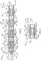
- the electrode 111comprises a stacked column 140 of one or more stimulation elements 112 and insulative elements 116, as illustrated in FIGS. 3 and 4 , which are simplified cross-sectional views of a portion of the stacked column 140, in accordance with embodiments of the invention.
- the stimulation and insulative elements 112 and 116are alternated in the stacked column. That is, at least one insulative element 116 is positioned between each pair of stimulation elements 112.
- the stimulation elements 112are formed of an electrically conductive and biocompatible material, such as alloys of silver, a platinum/iridium alloy (90-10), a nickel-chromium alloy, a gold alloy, or other noble metal alloys. In one embodiment, the stimulation elements 112 are approximately 0.5-5mm in length.
- the insulative elements 116are formed of a substantially electrically non-conductive and biocompatible material, such as a suitable polymer.
- electrical wires 118are coupled to the lead 106 and are configured to deliver electrical signals from the control unit 102 to each of the stimulation elements 112.
- Each of the wires 118is electrically coupled to one of the stimulation elements 112, in accordance with known methods.
- the wires 118are fed from a proximal end 141 of the stacked column 140 to the stimulation elements 112 through an internal cavity 142.
- control unit 102is configured to selectively apply a desired stimulation waveform to any one of the stimulation elements 112 through the wires 118. This allows for the interrogation of the stimulation elements 112 in order to identify the stimulation element 112 that is producing the best treatment results. Thus, the location of the stimulation can be optimized to produce the desired stimulation effect without having to reposition the electrode 111.
- the stimulation element 112comprises a body 143, a first end 144 and a second end 146.
- the insulative element 116comprises a body 148, a first end 150 and a second end 152.
- the first end 144 and the second end 146 of the body 143 of the stimulation element 112are configured to respectively interconnect with the second end 152 and the first end 150 of the body 148 of the insulative elements 116, as shown in FIG. 3 .
- the first end 144 and/or the second end 146 of the body 143 of the stimulation element 112comprises a receptacle 154 that is configured to receive a socket or protrusion 156 formed at the first end 150 and/or the second end 152 of the body 148 of the insulative element 116, as shown in FIG. 3 .
- the first end 144 and/or the second end 146 of the body 143 of the stimulation element 112can include a socket or protrusion 158 that can be received within a receptacle 160 formed in the first end 150 and/or the second end 152 of the body 148 of the insulative element 116, as shown in FIG. 4 .
- the receptacles and protrusions described aboveoperate to facilitate the interconnection of the stimulation elements 112 to the insulative elements 116.
- a biocompatible adhesive or other conventional meanscan be used to secure the connections between the stimulation elements 112 and the insulative elements 116, if necessary.
- the stimulation elements 112 and the insulative elements 116are generally cylindrically shaped and are interconnected such that they are coaxial to a central axis 162.
- FIGS. 3 and 4illustrate an anchor 120 that comprises one or more suture wings 172 that are attached to either the insulative element 116 ( FIG. 3 ) or the stimulation element 112 ( FIG. 4 ).
- the suture wings 172are integral to either the stimulation element 112 or the insulative element 116.
- each suture wing 172comprises a first end 174, a second end 176 and an intermediary portion 178.
- the first end 174 and the second end 176 of the suture wing 172are attached to the body 143 of the stimulation element 112 ( FIG. 4 ), or the body 148 of the insulative element 116 ( FIG. 3 ).
- the intermediary portion 178extends between the first end 174 and the second end 176 and is displaced from the corresponding body 143 or 148.
- the suture wing 172forms a suture hole 180, through which a suture can be threaded to facilitate the anchoring of the electrode lead 104 to the desired tissue of the patient.
- the width of the electrode 111 including that of the anchor 120is set to allow the electrode 111 to be deployed into the desired tissue of the patient using a trocar or other device.
- the width of the anchor 120can be set based on the location and orientation of the suture wings 172, the displacement of the intermediary portion 178 from the stimulation or insulative elements 112 and 116, and the width of the stimulation and insulative elements 112 and 116.
- the fixation elementhas a width of less than 12mm.
- Additional embodiments of the anchor 120include staggering the suture wings 172 at different radial angles relative to the central axis 162; orienting the suture wings 172 such that they are substantially parallel to the central axis 162 ( FIGS. 4 and 5 ); and orienting the suture wings 172 such that they are at an oblique angle (non-parallel) to the central axis 162; orienting the suture wings 172 such that they are transverse to the central axis 162.
- FIGS. 5 and 6are simplified side-cross sectional views of an anchor 120 that comprises a body 190 and a suture lock 192.
- the body 190may be attached to the lead body 110 or the electrode 111 and can be formed of any suitable biocompatible material.
- the body 190is substantially cylindrical in shape in a plane that is transverse to a longitudinal axis 195.
- the body 190comprises a recessed portion 196 that is configured to receive a winding of a suture 198, as shown in FIG. 5 .
- the recessed portion 196has a diameter that is sufficiently less than the diameter of a cylindrical portion 200 such that the recessed portion 196 can accommodate a desired amount of the suture 198 without having the suture 198 extend beyond the diameter of the cylindrical portion 200, as shown in FIG. 5 .
- the recessed portion 196comprises an annular groove 202 that extends around the longitudinal axis 195 of the body 190.
- the recessed portion 196can accommodate a length of suture 198 (e.g., Deklene II, Genzyme Corp.) in the range of 3cm; other suitable suture materials may be used.
- the cylindrical portion 200is positioned at a proximal end 204 of the body 190 and a tapered portion 206 of the body 190 is positioned at a distal end 208.
- the tapered portion 206has a diameter that generally decreases with distance along the longitudinal axis 195 of the body 190 in the distal direction, as shown in FIG. 5 .
- the tapered portion 206can be conical in shape and have a blunt or pointed leading end 210 to facilitate easy insertion into the desired tissue of the patient.
- the body 190 of the anchor 120includes a needle receptacle 212 that is configured to receive a needle 214, as shown in FIG. 5 .
- the needle receptacle 212is formed coaxial to the longitudinal axis 195 and has an opening at the leading end 210.
- the needle 214can be removably received within the needle receptacle 212.
- the needle 214can be formed of nickel titanium (NiTi) or other material and has a quiescent shape that is curved.
- the needle 214can be flexed from the curved quiescent state such that it can be inserted within the needle receptacle 212.
- the suture 198includes an end 216 that is attached to the needle 214 and an opposing end that is attached to the body 190.
- the suture lock 192is configured to secure an end of the suture 198 to the body 190 of the anchor 120.
- the suture lock 192comprises a passageway 220 that is formed in the body 190 and is configured to receive the suture 198, as shown in FIG. 6 .
- FIGS. 7-10are magnified side cross-sectional views of the suture lock in accordance with embodiments described herein.
- One embodiment of the suture lock 192includes a pinching component 222 that is configured to pinch a portion 223 of the suture 198 and prevent movement of the portion 223 of the suture 198 in a longitudinal direction (represented by arrow 224) relative to the pinching component 222.
- the passageway 220comprises a bore 221 through the body 190.
- the bore of the passageway 220is transverse to the longitudinal axis 195 of the body 190, as illustrated in FIG. 5 .
- the passageway 220passes through the needle receptacle 212, as shown in FIG. 5 .
- the passageway 220is formed on an exterior surface of the body 190.
- the passageway 220can be a groove, such as an annular groove, formed on the exterior surface of the body 190.
- the pinching component 222operates to form a radial constriction 226 in the passageway 220 that compresses the suture 198, as illustrated in FIGS. 7-10 , and secures the portion 223 of the suture 198 within the passageway 220 to prevent its movement relative to the passageway 220 in the longitudinal direction 224.
- the pinching component 222comprises one or more protuberances 228 formed by the walls of the passageway 220, as illustrated in FIGS. 7 and 8 , or an insert placed in the passageway 220.
- the pinching component 222is formed by one or more fingers 230 that extend into the passageway 220, as shown in FIGS. 9 and 10 . The fingers 230 may be insert-molded into the body 190 in accordance with conventional techniques.
- the anchor 120is used to anchor the electrode 111 in place after the electrode 111 has been inserted into a desired pelvic muscle or other tissue of the patient. Any conventional technique may be used to place the electrode 111 in the desired tissue of the patient, such as using a trocar.
- the processes described below for anchoring the electrode 111 using embodiments of the anchor 120 described abovecan be performed in any surgically appropriate manner, such as endoscopically.
- the surgeoncan attach an end of a suture to one of the suture wings 172 and attach the other end of the suture to a needle.
- the needlecan be passed through the tissue of the patient and through the suture holes 180 of one or more of the suture wings 172.
- the surgeoncan then secure the distal end of the suture to the electrode, such as to one of the suture wings 172, and remove the excess suture and needle to complete the anchoring of the electrode lead 104 to the tissue of the patient.
- the suture wings 172could be used with other fastening methods besides suture.
- surgical clips or staplescould be used. These devices are made of stainless steel or titanium and are bent by a delivery instrument. Endoscopic clip appliers are commonly used during less invasive surgical procedures.
- the anchor 120can initially be inserted into the tissue substantially in the form illustrated in FIG. 5 .
- the anchor 120can include the suture 198 with one end of the suture 198 attached to the body 190 and the other end 216 of the suture 198 attached to the needle 214.
- the suture 198is wound about a recessed portion 196 and the needle 214 is received within a needle receptacle 212.
- the electrode 111can then be inserted into the desired tissue of the patient using a trocar or other technique.
- the surgeoncan remove the needle 214 from the needle receptacle 212 and the anchor 120 can be rotated about the longitudinal axis 195 to unwind the suture 198 from the recessed portion 196.
- the fixation componentlacks the needle 214
- the surgeoncan attach a needle to the end 216 of the suture 198 after it has been unwound from the anchor 120.
- the surgeoncan thread the unwound suture through the tissue 240 surrounding the electrode lead 104, as illustrated in FIG. 6 .
- the surgeoncan then pass the needle 214 through the suture lock 192 such that the suture 198 is received within the passageway 220 of the suture lock 192 and is pinched by the pinching component 222 to secure the suture 198 within the suture lock 192, as described above.
- the surgeoncan then cut the excess suture 198 and remove the needle and excess suture from the patient.
- the fixation of the suture 198 within the suture lock 192completes the anchoring of the electrode lead 104 to the tissue of the patient.
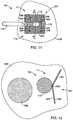
- FIG. 11illustrates a simplified side view of a distal end 114 of an electrode lead 104 having a lead body 110, an electrode 111 and an anchor 257, in accordance with embodiments described herein, that is implanted in tissue 258 of a patient.
- FIG. 12provides a cross-sectional view of the anchor 257 taken generally along line 12-12 of FIG. 11 and illustrates the implantation of the distal end 114 of the electrode adjacent a structure 259 of the patient.
- one embodiment of the electrode 111comprises one or more stimulation elements 112, each located at a distal end 114 of the lead body 110.
- the stimulation elements 112may be separated by an insulating element 116, which may comprise the lead body 110.
- the anchor 257comprises an anchor body, such as the lead body 110 ( FIG. 11 ) or other component that is attached to the lead body 110, and a section of mesh 260 attached to the anchor body.
- the bio-compatible mesh 260is preferably an open matrix mesh, such as a mesh constructed of polypropylene monofilament.
- the mesh 260comprises one or more mesh sections or wings, such as wings 261 and 262.
- the mesh 260has a compact state and an expanded state. In general, at least a portion of the mesh 260 is displaced a greater distance from the anchor body 110 when in the expanded state than when in the compact state.
- the anchor 257is generally in a form suitable for implantation in the tissue 258 when the mesh 260 is in the compact state and performs its anchoring function in the tissue 258 when the mesh 260 is in the expanded state, in which tissue 258 in-growth through mesh prevents the mesh 260 and the attached stimulation electrodes 112 from moving relative to the tissue 258.
- the mesh 260has a shape memory that drives the mesh to a preset expanded, quiescent shape, in which at least a portion of the mesh 260 extends away from the anchor body 110 and into the surrounding tissue 258.
- the quiescent shape of the mesh 260is one in which the mesh will naturally return to after being deformed, such as when compressed into a compact state.
- the expanded state of the mesh wings 261 and 262is one in which the wings 261 and 262 are displaced from each other, such as illustrated in FIG. 12 .
- one embodiment of the mesh 260has a shape memory that encourages separation of the one or more wings, such as wings 261 and 262, within the tissue 258.
- the anchor 257is configured to deliver electrical signals from the control unit to the tissue 258.
- the mesh 260comprises the one or more stimulation elements 112 of the electrode 111 that are used to deliver electrical signals to the tissue 258.
- one or more conductive fibers 264are attached to the mesh 260 and conduct electrical signals from one or more of the stimulation elements 112 of the lead body ( FIG. 11 ), or the control unit 102, into the tissue 258.
- the electrode 111comprises one or more conductive fibers 264 configured to conduct electrical signals from the control unit 102 to one or more electrically conductive nodes or stimulation elements 266, which are attached to the mesh 260.
- the wires 264are electrically insulated from the tissue 258.
- the stimulation elements 266deliver the electrical signals to the tissue 258.
- the wires 264electrically couple the stimulation elements 112 to one of the stimulation elements 266.
- a portion of the mesh 260is attached to the distal end 114 of the lead body 110 at a location 268.
- Exemplary means for attaching the mesh 260 to the lead body 110include sutures, glue, anchors, or other suitable bio-compatible methods.
- the attachment location 268comprises a central portion of the mesh 260.
- one embodiment of the anchor 257comprises at least two wings of mesh 261 and 262 that extend from the distal end of the lead body 110 at the connection location 268.
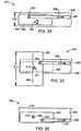
- FIG. 13is a simplified cross-sectional view of the distal end 114 of the lead body 110 having the anchor 257 installed in a delivery trocar 270 that is used to implant the electrode 111 in the desired tissue 258 of the patient.
- the mesh 260 of the anchor 257is placed in the compact state (e.g., rolled up) and installed in the trocar 270.
- the anchor 257is deployed from the trocar 270 into the tissue 258, the mesh 260 expands toward the expanded state or its expanded quiescent shape. Tissue in-growth secures the mesh 260 to the tissue 258 to anchor the location of the electrode 111.
- the mesh 260comprises the wings 261 and 262, the wings 261 and 262 compressed into the compact state, as shown in FIG. 13 .
- the mesh wings 261 and 262extend from the connection point 268 away from the distal end 114 of the lead body 110.
- the mesh sections 261 and 262move toward the preset expanded quiescent shape and into the tissue 258, as shown in FIG. 12 . In-growth of the tissue 258 into the mesh 260 operates to anchor the mesh 260 to the tissue 258, thereby anchoring the electrode 111 in the desired position.
- the mesh 260is deployed in the tissue 258 such that it has a desired orientation relative to the structure 259 of the patient.
- the expansion of the mesh 260can be directed to a side of the lead body 110 such that it expands away from the structure 259 or toward the structure 259.
- the distal end 114 of the lead body 110can be oriented relative to the urethra 259 such that the mesh 260 is located on a side of the lead body 110 that is away from the urethra 259. This prevents fibrosis around the mesh 260 from interfering with the communication of electrical stimulation signals from the electrode lead 104 to the structure 259.
- the anchor 257is initially provided in a sterilized and sealed package, in which the mesh 260, such as mesh sections 261 and 262, have a quiescent shape in which they lie substantially flat, as illustrated in the simplified cross-sectional view of FIG. 14.
- FIG. 15is a simplified side view of an installation tool 276 in accordance with embodiments described herein that is used to prepare the anchor 257 for installation within a trocar 270.
- the tool 276comprises a forked end 278 that includes prongs 280 and 282 that extend substantially parallel to the longitudinal axis 284 of the tool 276.
- a gap 286 between the prongs 280 and 282is configured to receive an end of the mesh 260.
- the anchor 257is prepared for installation within a trocar 270 by placing an end of the mesh 260 through the gap 286 and rotating the tool 276, such as in the direction indicated by arrow 290, to roll up the mesh 260, as illustrated in simplified front cross-sectional views of FIGS. 16 and 17 .
- the distal end 114 of the lead body 110 and the anchor 257can be installed in a trocar 270, as illustrated in the simplified cross-sectional view of FIG. 18 .
- the end 278 of the tool 276is disengaged from the mesh 260 either prior to or after the insertion of the distal end 114 within the trocar 270.
- the mesh 260expands toward its expanded quiescent shape within the tissue 258, as discussed above.
- FIGS. 19 and 20respectively are front and side cross-sectional views of a distal end 114 of the electrode lead 104 comprising the anchor 257 installed within a trocar 270, in accordance with embodiments described herein.
- a tool 292is installed in the trocar 270 to aid in the deployment of the mesh wings 261 and 262.
- the tool 292operates to separate the mesh wings 261 and 262 and prevent their entanglement within the trocar 270.
- the tool 292is configured to cause or assist in the expansion of the mesh wings 261 and 262 into the tissue 258 after deployment of the distal end 114 into the tissue 258.
- the trocar 270is partially retracted, as illustrated in the side cross-sectional view of FIG. 21 .
- the cross-sectional width of the end 294 of the tool 292is expanded, which drives the mesh wings 261 and 262 away from each other within the tissue 258, as illustrated in FIG. 22 .
- the distal end 294 of the tool 292can then be withdrawn into the trocar 270 and removed from the patient through the trocar 270 to complete the implantation of the distal end 114 of the lead body 110 within the tissue 258 of the patient, as illustrated in the cross-sectional view of FIG. 23 .
- the cross-sectional width of the end 294 of the tool 292is reduced prior to its withdrawal from the patient.
- the tool 292comprises a scissor-like mechanism that expands the effective width of the distal end 294.
- FIGS. 24-26are simplified side views of a tool 292 in accordance with embodiments described herein.
- the tool 292comprises first and second elongated components 296 and 298 that are respectively coupled to a third component 300 through hinges 302 and 304.
- the initial width 306 of the tool 292allows the tool 292 to be received within the trocar 270, as shown in FIGS. 19 and 20 .
- component 296is moved relative to component 298, such as, for example, in the direction indicated by arrow 308.
- the displacement of the hinge 304 from the hinge 302 in the widthwise directioncauses the component 300 to pivot about the hinge 302 relative to the component 298 in the direction indicated by arrow 310 to an expanded position, as shown in FIG. 25 .
- the width 312 of the distal end 294 of the tool 292 in the expanded positionis significantly greater than the width 306. This expansion of the width of the distal end 294 drives the expansion of the mesh wings 261 and 262, as illustrated in FIG. 22 .
- the component 296can be further moved relative to the component 298 in a direction indicated by arrow 308 to place the distal end 294 in a compacted state ( FIG. 26 ), in which the tool 292 may either be received again within the trocar 270, or otherwise removed from the patient, while leaving the distal end 114 of the lead body 110 in the desired location within the tissue 258 of the patient.
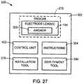
- FIG. 27illustrates a kit 320 in accordance with embodiments described herein.
- the kitincludes a package 322 containing components including one or more electrode leads 104 in accordance with one or more of the embodiments described above.
- the kit 320includes the control unit 102.
- the kitincludes instructions 324 for installing the one or more electrode leads 104 in the patient.
- the instructions 324include instructions for installing the control unit 102.
- the kit 320includes the installation tool 278.
- the kit 320includes the deployment tool 292.
- the one or more electrode leads 104 in the kit 320include an anchor 326 in accordance with one or more of the embodiments described above, such as anchor 120 or 257.
- the distal end 114 of the one or more electrode leadsare provided pre-installed in a trocar 270.
- one or more toolssuch as installation tool 278 or deployment tool 292, are provided in the kit 320.
- Embodiments of the instructions 324include instructions for implanting the distal end 114 of the electrode lead 104 within tissue 258 of the patient using the trocar 270, tool 278 and/or tool 292. Such instructions include instructions describing one or more of the method steps discussed above with reference to FIGS. 16-26 .
- tissue anchor120,257
- tissue anchor120,257
- mechanical support132
Landscapes
- Health & Medical Sciences (AREA)
- Nuclear Medicine, Radiotherapy & Molecular Imaging (AREA)
- Animal Behavior & Ethology (AREA)
- Veterinary Medicine (AREA)
- Cardiology (AREA)
- Heart & Thoracic Surgery (AREA)
- Engineering & Computer Science (AREA)
- Public Health (AREA)
- Radiology & Medical Imaging (AREA)
- Biomedical Technology (AREA)
- Life Sciences & Earth Sciences (AREA)
- General Health & Medical Sciences (AREA)
- Neurology (AREA)
- Neurosurgery (AREA)
- Orthopedic Medicine & Surgery (AREA)
- Electrotherapy Devices (AREA)
Description
- Implantable electronic stimulator devices, such as neuromuscular stimulation devices, have been disclosed for use in the treatment of various pelvic conditions, such as urinary incontinence, fecal incontinence and sexual dysfunction. Such devices generally include one or more electrodes that are coupled to a control unit by electrode leads. Electrical signals are applied to the desired pelvic tissue of the patient through the electrode leads in order to treat the condition of the patient. The electrode leads are typically secured to the tissue using an anchor in the form of a helical coil. Exemplary implantable electronic stimulator devices and uses of the devices are disclosed in
U.S. Patent Nos. 6,354,991 ,6,652,449 ,6,712,772 and6,862,480 . - Urinary incontinence in women has been treated by a surgical method involving the placement of a sling to stabilize or support the bladder neck or urethra of the patient. Varieties of sling procedures are described in
U.S. Pub. No. 2002-016382 A1 . One type of sling procedure is a pubovaginal sling procedure, which is a minimally invasive surgical method involving the placement (e.g. by the use of a Stamey needle or other ligature carrier) of a sling to stabilize or support the bladder neck or urethra. This procedure does not utilize bone anchors. Rather the sling is anchored in the abdominal or rectus fascia. U.S. Pub. No. 2007-0260288 A1 generally describes a combination of the above devices. One or more electrodes are attached to a mechanical support, such as a sling, that supports a portion of the urethra of the patient. The electrodes are configured to contact tissue of the patient when the mechanical support is implanted in the patient. A control unit drives the electrodes to apply a current to the tissue that treats a pelvic condition of the patient.U.S. Pub. No. 2009-0012592 A1 generally describes an electrode lead with a body having a proximal end and a distal end, two stimulating electrodes and an anchor. The above-described devices utilize anchors to secure components of the devices, such as electrode leads and/or mechanical supports, in tissue of the patient. It is desirable, for example, that such anchors prevent relative movement between the anchor and the tissue in which the anchor in embedded, are easy to install in the tissue, avoid damaging the tissue during the implantation procedure, operate as electrical stimulators, can be temporarily moved relative to the tissue without significant restriction by the anchor during installation, can be removed without significantly damaging the tissue, and/or have other features or benefits recognized by those skilled in the art.- The invention is directed to an electrode lead for facilitating electrical stimulation of tissue in a patient in accordance with claim 1. The electrode lead comprises a lead body, an electrode attached to a distal end of the lead body and a tissue anchor. The electrode comprises a plurality of stimulation elements formed of an electrically conductive material, and at least one insulative element formed of an electrically non-conductive material. The stimulation elements and the at least one insulative element are joined together to form a stacked column of alternating stimulation and insulative elements. The electrode lead also comprises a plurality of electrically conductive wires each extending through the lead body and coupled to one of the stimulation elements. The tissue anchor is configured to facilitate anchoring the electrode to tissue of the patient.
- This Summary is provided to introduce a selection of concepts in a simplified form that are further described below in the Detailed Description. This Summary is not indented to identify key features or essential features of the claimed subject matter, nor is it intended to be used as an aid in determining the scope of the claimed subject matter. The claimed subject matter is not limited to implementations that solve any or all disadvantages noted in the Background.
FIG. 1 is a side plan view of an exemplary electronic stimulator device, in accordance with the embodiments described herein.FIG. 2 is a schematic illustration of a pelvic treatment apparatus in accordance with embodiments described herein.FIGS. 3 and 4 are simplified cross-sectional views of a portion of an electrode lead in accordance with embodiments of the invention.FIGS. 5 and 6 are simplified side cross-sectional views of an anchor in accordance with embodiments described herein.FIGS. 7-10 are magnified side cross-sectional views of a suture lock in accordance with embodiments described herein.FIG. 11 is a simplified side view of an electrode lead comprising an anchor in accordance with embodiments described herein.FIG. 12 is a side cross-sectional view of the electrode lead ofFIG. 11 taken generally along line 12-12.FIG. 13 is a front cross-sectional view of a distal end of an electrode lead installed within a trocar.FIG. 14 is a simplified front cross-sectional view of a distal end of an electrode lead comprising an anchor in accordance with embodiments described herein.FIG. 15 is a partial side view of an installation tool in accordance with embodiments described herein.FIGS. 16-18 are simplified front cross-sectional views of the distal end of an electrode lead illustrating a method of installing the electrode lead within a trocar.FIG. 19 is a simplified front cross-sectional view of an electrode lead installed within a trocar along with a tool in accordance with embodiments described herein.FIG. 20 is a side cross-sectional view ofFIG. 19 taken generally along line 20-20.FIGS. 21-23 illustrate method steps of deploying the distal end of the electrode lead ofFIGS. 19 and 20 within tissue of a patient, in accordance with embodiments described herein.FIGS. 24-26 are simplified side views of an electrode lead installation tool in accordance with embodiments described herein.FIG. 27 is a block diagram of a kit in accordance with embodiments described herein.- Embodiments are directed to an anchor that facilitates securing implantable devices or components, such as electrode leads, mechanical supports (e.g., meshes, slings), and other devices or components to internal tissue of a patient, and preventing migration of the devices or components from their intended position.
- The tissue in which the anchor may be used includes adipose tissue, muscle tissue or any other tissue of the patient. In one embodiment, the tissue is located in the pelvic region of the patient. In some embodiments, the tissue, in which the anchor is to be embedded, is targeted for electrical stimulation or is adjacent a desired stimulation target site. Embodiments of the invention comprise the individual embodiments described below and combinations of two or more of the embodiments described below.
- Initially, exemplary devices or components with which the anchors may be used will be discussed.
FIG. 1 is a side plan view of an exemplaryelectronic stimulator device 100, with which embodiments of the anchors may be used.Device 100 is configured for implantation into a pelvic region of a patient to provide muscle and/or nerve stimulation that is used to control and/or treat a pelvic condition of the patient, such as pelvic pain, urinary incontinence, fecal incontinence, erectile dysfunction or other pelvic condition that may be treated through electrical stimulation. - In one embodiment, the
device 100 comprises acontrol unit 102 and one or more electrode leads 104, aproximal end 106 of which is coupled to thecontrol unit 102 via aconnector 108. Eachelectrode lead 104 comprises alead body 110 and anelectrode 111 attached to thelead body 110. One embodiment of theelectrode 111 includes one ormore stimulation elements 112 at adistal end 114 of theelectrode lead 104 orlead body 110. In one embodiment, thestimulation elements 112 are separated from each other by aninsulative element 116. Thelead body 110 insulateselectrical wires 118 connecting thecontrol unit 102 to thestimulation elements 112. Thelead body 110 can be in the form of an insulating jacket typically comprising silicone, polyurethane or other flexible, biocompatible electrically insulating material. Additional electrode leads 104 or physiological sensors may be coupled to thecontrol unit 102. - In one embodiment, the
control unit 102 comprises circuitry for processing electrical signals received from the one ormore stimulation elements 112 or physiological sensors (not shown). Thecontrol unit 102 is also configured to apply an electrical current or waveform to the tissue of the patient that is in contact with the one ormore stimulation elements 112. - The
electrode 111 can be anchored to pelvic tissue of the patient (e.g., internal urinary sphincter muscle) by means of atissue anchor 120, which is formed in accordance with embodiments described below. Theanchor 120 operates to secure the position of theelectrode 111 in the desired tissue of the patient. Theanchor 120 can be coupled to thelead body 110 or thestimulation element 112. In one embodiment, theanchor 120 operates to provide electrical contact between the pelvic tissue of the patient and the one ormore stimulation elements 112 of theelectrode 111. - Another device or component with which embodiments of the
anchor 120 may be used is apelvic treatment apparatus 130, an example of which is illustrated inFIG. 2 . Thepelvic treatment apparatus 130 can be used to treat, for example, urinary incontinence of a patient, and generally comprises amechanical support 132, which can be in the form of a mesh or other mechanical support. Themechanical support 132 can be installed in the patient to, for example, provide support to the neck of thebladder 134 or the urethra of the patient, which are generally indicated at 136. Themechanical support 132 can be configured for implantation by any number of known surgical approaches, for example, a suprapubic approach, a transvaginal approach, a retropubic approach, and a transobturator approach. - In one embodiment, the
mechanical support 132 is anchored to pelvic tissue of the patient using one ormore anchors 120 described below. Eachanchor 120 can be attached to acable 138 or directly attached to themechanical support 132. - In one embodiment, the
pelvic treatment apparatus 130 includes one ormore stimulation elements 112 that are attached to themechanical support 132 or extend from themechanical support 132 on electrode leads (not shown), such as those described above with reference toFIG. 1 . Acontrol unit 102, located inside or outside of the patients body, drives thestimulation elements 112 to apply a current to a pelvic site and treat, for example, stress incontinence, urge incontinence, urge frequency, erectile dysfunction, or other pelvic dysfunctions. In accordance with embodiments described herein, themechanical support 132 and the attachedstimulation elements 112 may be referred to as an electrode lead, wherein thesupport 132 forms the lead body and thestimulation elements 112 form the electrode. - One embodiment of the
electrode 111 comprises a stackedcolumn 140 of one ormore stimulation elements 112 andinsulative elements 116, as illustrated inFIGS. 3 and 4 , which are simplified cross-sectional views of a portion of the stackedcolumn 140, in accordance with embodiments of the invention. In one embodiment, the stimulation andinsulative elements insulative element 116 is positioned between each pair ofstimulation elements 112. - In one embodiment, the
stimulation elements 112 are formed of an electrically conductive and biocompatible material, such as alloys of silver, a platinum/iridium alloy (90-10), a nickel-chromium alloy, a gold alloy, or other noble metal alloys. In one embodiment, thestimulation elements 112 are approximately 0.5-5mm in length. Theinsulative elements 116 are formed of a substantially electrically non-conductive and biocompatible material, such as a suitable polymer. - In one embodiment,
electrical wires 118 are coupled to thelead 106 and are configured to deliver electrical signals from thecontrol unit 102 to each of thestimulation elements 112. Each of thewires 118 is electrically coupled to one of thestimulation elements 112, in accordance with known methods. In one embodiment, thewires 118 are fed from aproximal end 141 of the stackedcolumn 140 to thestimulation elements 112 through aninternal cavity 142. - In one embodiment, the
control unit 102 is configured to selectively apply a desired stimulation waveform to any one of thestimulation elements 112 through thewires 118. This allows for the interrogation of thestimulation elements 112 in order to identify thestimulation element 112 that is producing the best treatment results. Thus, the location of the stimulation can be optimized to produce the desired stimulation effect without having to reposition theelectrode 111. - In one embodiment, the
stimulation element 112 comprises abody 143, afirst end 144 and asecond end 146. Similarly, one embodiment of theinsulative element 116 comprises abody 148, afirst end 150 and asecond end 152. In one embodiment, thefirst end 144 and thesecond end 146 of thebody 143 of thestimulation element 112 are configured to respectively interconnect with thesecond end 152 and thefirst end 150 of thebody 148 of theinsulative elements 116, as shown inFIG. 3 . In one embodiment, thefirst end 144 and/or thesecond end 146 of thebody 143 of thestimulation element 112 comprises areceptacle 154 that is configured to receive a socket orprotrusion 156 formed at thefirst end 150 and/or thesecond end 152 of thebody 148 of theinsulative element 116, as shown inFIG. 3 . Alternatively, thefirst end 144 and/or thesecond end 146 of thebody 143 of thestimulation element 112 can include a socket orprotrusion 158 that can be received within areceptacle 160 formed in thefirst end 150 and/or thesecond end 152 of thebody 148 of theinsulative element 116, as shown inFIG. 4 . The receptacles and protrusions described above operate to facilitate the interconnection of thestimulation elements 112 to theinsulative elements 116. A biocompatible adhesive or other conventional means can be used to secure the connections between thestimulation elements 112 and theinsulative elements 116, if necessary. - In one embodiment, the
stimulation elements 112 and theinsulative elements 116 are generally cylindrically shaped and are interconnected such that they are coaxial to acentral axis 162. - One embodiment of the
electrode lead 104 comprises an anchor 120 (illustrated schematically inFIG. 1 ) that is configured to facilitate the anchoring of theelectrode 111 to the desired tissue of the patient.FIGS. 3 and 4 illustrate ananchor 120 that comprises one ormore suture wings 172 that are attached to either the insulative element 116 (FIG. 3 ) or the stimulation element 112 (FIG. 4 ). In one embodiment, thesuture wings 172 are integral to either thestimulation element 112 or theinsulative element 116. - In one embodiment, each
suture wing 172 comprises afirst end 174, asecond end 176 and anintermediary portion 178. Thefirst end 174 and thesecond end 176 of thesuture wing 172 are attached to thebody 143 of the stimulation element 112 (FIG. 4 ), or thebody 148 of the insulative element 116 (FIG. 3 ). Theintermediary portion 178 extends between thefirst end 174 and thesecond end 176 and is displaced from thecorresponding body suture wing 172 forms asuture hole 180, through which a suture can be threaded to facilitate the anchoring of theelectrode lead 104 to the desired tissue of the patient. - In one embodiment, the width of the
electrode 111 including that of theanchor 120 is set to allow theelectrode 111 to be deployed into the desired tissue of the patient using a trocar or other device. The width of theanchor 120 can be set based on the location and orientation of thesuture wings 172, the displacement of theintermediary portion 178 from the stimulation orinsulative elements insulative elements - Additional embodiments of the
anchor 120 include staggering thesuture wings 172 at different radial angles relative to thecentral axis 162; orienting thesuture wings 172 such that they are substantially parallel to the central axis 162 (FIGS. 4 and5 ); and orienting thesuture wings 172 such that they are at an oblique angle (non-parallel) to thecentral axis 162; orienting thesuture wings 172 such that they are transverse to thecentral axis 162. FIGS. 5 and 6 are simplified side-cross sectional views of ananchor 120 that comprises abody 190 and asuture lock 192. Thebody 190 may be attached to thelead body 110 or theelectrode 111 and can be formed of any suitable biocompatible material. In one embodiment, thebody 190 is substantially cylindrical in shape in a plane that is transverse to alongitudinal axis 195.- One embodiment of the
body 190 comprises a recessedportion 196 that is configured to receive a winding of asuture 198, as shown inFIG. 5 . In one embodiment, the recessedportion 196 has a diameter that is sufficiently less than the diameter of acylindrical portion 200 such that the recessedportion 196 can accommodate a desired amount of thesuture 198 without having thesuture 198 extend beyond the diameter of thecylindrical portion 200, as shown inFIG. 5 . In one embodiment, the recessedportion 196 comprises anannular groove 202 that extends around thelongitudinal axis 195 of thebody 190. In one exemplary embodiment, the recessedportion 196 can accommodate a length of suture 198 (e.g., Deklene II, Genzyme Corp.) in the range of 3cm; other suitable suture materials may be used. - In one embodiment, the
cylindrical portion 200 is positioned at aproximal end 204 of thebody 190 and atapered portion 206 of thebody 190 is positioned at adistal end 208. The taperedportion 206 has a diameter that generally decreases with distance along thelongitudinal axis 195 of thebody 190 in the distal direction, as shown inFIG. 5 . The taperedportion 206 can be conical in shape and have a blunt or pointed leadingend 210 to facilitate easy insertion into the desired tissue of the patient. - In one embodiment, the
body 190 of theanchor 120 includes aneedle receptacle 212 that is configured to receive aneedle 214, as shown inFIG. 5 . In one embodiment, theneedle receptacle 212 is formed coaxial to thelongitudinal axis 195 and has an opening at theleading end 210. Theneedle 214 can be removably received within theneedle receptacle 212. In one embodiment, theneedle 214 can be formed of nickel titanium (NiTi) or other material and has a quiescent shape that is curved. Preferably, theneedle 214 can be flexed from the curved quiescent state such that it can be inserted within theneedle receptacle 212. In one embodiment, thesuture 198 includes anend 216 that is attached to theneedle 214 and an opposing end that is attached to thebody 190. - The
suture lock 192 is configured to secure an end of thesuture 198 to thebody 190 of theanchor 120. In one embodiment, thesuture lock 192 comprises apassageway 220 that is formed in thebody 190 and is configured to receive thesuture 198, as shown inFIG. 6 .FIGS. 7-10 are magnified side cross-sectional views of the suture lock in accordance with embodiments described herein. One embodiment of thesuture lock 192 includes apinching component 222 that is configured to pinch aportion 223 of thesuture 198 and prevent movement of theportion 223 of thesuture 198 in a longitudinal direction (represented by arrow 224) relative to thepinching component 222. - In one embodiment, the
passageway 220 comprises abore 221 through thebody 190. In one embodiment, the bore of thepassageway 220 is transverse to thelongitudinal axis 195 of thebody 190, as illustrated inFIG. 5 . In another embodiment, thepassageway 220 passes through theneedle receptacle 212, as shown inFIG. 5 . In accordance with another embodiment, thepassageway 220 is formed on an exterior surface of thebody 190. For example, thepassageway 220 can be a groove, such as an annular groove, formed on the exterior surface of thebody 190. - In one embodiment, the
pinching component 222 operates to form aradial constriction 226 in thepassageway 220 that compresses thesuture 198, as illustrated inFIGS. 7-10 , and secures theportion 223 of thesuture 198 within thepassageway 220 to prevent its movement relative to thepassageway 220 in thelongitudinal direction 224. In one embodiment, thepinching component 222 comprises one ormore protuberances 228 formed by the walls of thepassageway 220, as illustrated inFIGS. 7 and 8 , or an insert placed in thepassageway 220. In accordance with another embodiment, thepinching component 222 is formed by one ormore fingers 230 that extend into thepassageway 220, as shown inFIGS. 9 and 10 . Thefingers 230 may be insert-molded into thebody 190 in accordance with conventional techniques. - The
anchor 120 is used to anchor theelectrode 111 in place after theelectrode 111 has been inserted into a desired pelvic muscle or other tissue of the patient. Any conventional technique may be used to place theelectrode 111 in the desired tissue of the patient, such as using a trocar. The processes described below for anchoring theelectrode 111 using embodiments of theanchor 120 described above can be performed in any surgically appropriate manner, such as endoscopically. - For the embodiments of the
anchor 120 illustrated inFIGS. 3 and 4 , the surgeon can attach an end of a suture to one of thesuture wings 172 and attach the other end of the suture to a needle. The needle can be passed through the tissue of the patient and through the suture holes 180 of one or more of thesuture wings 172. The surgeon can then secure the distal end of the suture to the electrode, such as to one of thesuture wings 172, and remove the excess suture and needle to complete the anchoring of theelectrode lead 104 to the tissue of the patient. - The
suture wings 172 could be used with other fastening methods besides suture. For example, surgical clips or staples could be used. These devices are made of stainless steel or titanium and are bent by a delivery instrument. Endoscopic clip appliers are commonly used during less invasive surgical procedures. - When the
anchor 120 is formed in accordance with the embodiments described above with regard toFIGS. 5 and 6 , theanchor 120 can initially be inserted into the tissue substantially in the form illustrated inFIG. 5 . For example, theanchor 120 can include thesuture 198 with one end of thesuture 198 attached to thebody 190 and theother end 216 of thesuture 198 attached to theneedle 214. In one embodiment, thesuture 198 is wound about a recessedportion 196 and theneedle 214 is received within aneedle receptacle 212. Theelectrode 111 can then be inserted into the desired tissue of the patient using a trocar or other technique. - Once inserted into the desired location, the surgeon can remove the
needle 214 from theneedle receptacle 212 and theanchor 120 can be rotated about thelongitudinal axis 195 to unwind thesuture 198 from the recessedportion 196. In the event that the fixation component lacks theneedle 214, the surgeon can attach a needle to theend 216 of thesuture 198 after it has been unwound from theanchor 120. The surgeon can thread the unwound suture through thetissue 240 surrounding theelectrode lead 104, as illustrated inFIG. 6 . The surgeon can then pass theneedle 214 through thesuture lock 192 such that thesuture 198 is received within thepassageway 220 of thesuture lock 192 and is pinched by thepinching component 222 to secure thesuture 198 within thesuture lock 192, as described above. The surgeon can then cut theexcess suture 198 and remove the needle and excess suture from the patient. The fixation of thesuture 198 within thesuture lock 192 completes the anchoring of theelectrode lead 104 to the tissue of the patient. FIG. 11 illustrates a simplified side view of adistal end 114 of anelectrode lead 104 having alead body 110, anelectrode 111 and ananchor 257, in accordance with embodiments described herein, that is implanted intissue 258 of a patient.FIG. 12 provides a cross-sectional view of theanchor 257 taken generally along line 12-12 ofFIG. 11 and illustrates the implantation of thedistal end 114 of the electrode adjacent astructure 259 of the patient.- As discussed above, one embodiment of the
electrode 111 comprises one ormore stimulation elements 112, each located at adistal end 114 of thelead body 110. Thestimulation elements 112 may be separated by an insulatingelement 116, which may comprise thelead body 110. - One embodiment of the
anchor 257 comprises an anchor body, such as the lead body 110 (FIG. 11 ) or other component that is attached to thelead body 110, and a section ofmesh 260 attached to the anchor body. To simplify the discussion of embodiments of theanchor 257, the anchor body will be described and generally depicted as thelead body 110. Thebio-compatible mesh 260 is preferably an open matrix mesh, such as a mesh constructed of polypropylene monofilament. In one embodiment, themesh 260 comprises one or more mesh sections or wings, such aswings - In one embodiment, the
mesh 260 has a compact state and an expanded state. In general, at least a portion of themesh 260 is displaced a greater distance from theanchor body 110 when in the expanded state than when in the compact state. Theanchor 257 is generally in a form suitable for implantation in thetissue 258 when themesh 260 is in the compact state and performs its anchoring function in thetissue 258 when themesh 260 is in the expanded state, in whichtissue 258 in-growth through mesh prevents themesh 260 and the attachedstimulation electrodes 112 from moving relative to thetissue 258. - In one embodiment, the
mesh 260 has a shape memory that drives the mesh to a preset expanded, quiescent shape, in which at least a portion of themesh 260 extends away from theanchor body 110 and into the surroundingtissue 258. As used herein, the quiescent shape of themesh 260 is one in which the mesh will naturally return to after being deformed, such as when compressed into a compact state. - In one embodiment, the expanded state of the
mesh wings wings FIG. 12 . Thus, one embodiment of themesh 260 has a shape memory that encourages separation of the one or more wings, such aswings tissue 258. - In one embodiment, the
anchor 257 is configured to deliver electrical signals from the control unit to thetissue 258. In one embodiment, themesh 260 comprises the one ormore stimulation elements 112 of theelectrode 111 that are used to deliver electrical signals to thetissue 258. In one embodiment, one or more conductive fibers 264 (FIG. 11 ) are attached to themesh 260 and conduct electrical signals from one or more of thestimulation elements 112 of the lead body (FIG. 11 ), or thecontrol unit 102, into thetissue 258. - In one embodiment, the
electrode 111 comprises one or moreconductive fibers 264 configured to conduct electrical signals from thecontrol unit 102 to one or more electrically conductive nodes orstimulation elements 266, which are attached to themesh 260. Thewires 264 are electrically insulated from thetissue 258. Thestimulation elements 266 deliver the electrical signals to thetissue 258. In one embodiment, thewires 264 electrically couple thestimulation elements 112 to one of thestimulation elements 266. - A portion of the
mesh 260 is attached to thedistal end 114 of thelead body 110 at alocation 268. Exemplary means for attaching themesh 260 to thelead body 110 include sutures, glue, anchors, or other suitable bio-compatible methods. In one embodiment, theattachment location 268 comprises a central portion of themesh 260. As a result, one embodiment of theanchor 257 comprises at least two wings ofmesh lead body 110 at theconnection location 268. FIG. 13 is a simplified cross-sectional view of thedistal end 114 of thelead body 110 having theanchor 257 installed in adelivery trocar 270 that is used to implant theelectrode 111 in the desiredtissue 258 of the patient. In one embodiment, themesh 260 of theanchor 257 is placed in the compact state (e.g., rolled up) and installed in thetrocar 270. When theanchor 257 is deployed from thetrocar 270 into thetissue 258, themesh 260 expands toward the expanded state or its expanded quiescent shape. Tissue in-growth secures themesh 260 to thetissue 258 to anchor the location of theelectrode 111.- When the
mesh 260 comprises thewings wings FIG. 13 . In one embodiment, themesh wings connection point 268 away from thedistal end 114 of thelead body 110. Upon deployment of theelectrode 111 into the desiredtissue 258 of the patient, themesh sections tissue 258, as shown inFIG. 12 . In-growth of thetissue 258 into themesh 260 operates to anchor themesh 260 to thetissue 258, thereby anchoring theelectrode 111 in the desired position. - In one embodiment, the
mesh 260 is deployed in thetissue 258 such that it has a desired orientation relative to thestructure 259 of the patient. As a result, the expansion of themesh 260 can be directed to a side of thelead body 110 such that it expands away from thestructure 259 or toward thestructure 259. For instance, when thestructure 259 is in the form of the urethra of the patient, thedistal end 114 of thelead body 110 can be oriented relative to theurethra 259 such that themesh 260 is located on a side of thelead body 110 that is away from theurethra 259. This prevents fibrosis around themesh 260 from interfering with the communication of electrical stimulation signals from theelectrode lead 104 to thestructure 259. - In one embodiment, the
anchor 257 is initially provided in a sterilized and sealed package, in which themesh 260, such asmesh sections FIG. 14. FIG. 15 is a simplified side view of aninstallation tool 276 in accordance with embodiments described herein that is used to prepare theanchor 257 for installation within atrocar 270. Thetool 276 comprises a forkedend 278 that includesprongs longitudinal axis 284 of thetool 276. Agap 286 between theprongs mesh 260. - The
anchor 257 is prepared for installation within atrocar 270 by placing an end of themesh 260 through thegap 286 and rotating thetool 276, such as in the direction indicated byarrow 290, to roll up themesh 260, as illustrated in simplified front cross-sectional views ofFIGS. 16 and 17 . Once themesh 260 has been rolled up into a compact state, thedistal end 114 of thelead body 110 and theanchor 257 can be installed in atrocar 270, as illustrated in the simplified cross-sectional view ofFIG. 18 . Theend 278 of thetool 276 is disengaged from themesh 260 either prior to or after the insertion of thedistal end 114 within thetrocar 270. When thedistal end 114 of thelead body 110 is deployed into the desiredtissue 258 of the patient using thetrocar 270, themesh 260 expands toward its expanded quiescent shape within thetissue 258, as discussed above. FIGS. 19 and 20 respectively are front and side cross-sectional views of adistal end 114 of theelectrode lead 104 comprising theanchor 257 installed within atrocar 270, in accordance with embodiments described herein. Atool 292 is installed in thetrocar 270 to aid in the deployment of themesh wings - In one embodiment, the
tool 292 operates to separate themesh wings trocar 270. - In one embodiment, the
tool 292 is configured to cause or assist in the expansion of themesh wings tissue 258 after deployment of thedistal end 114 into thetissue 258. In one embodiment, once thedistal end 114 of thelead body 110 held in thetrocar 270 is located at the desired position within thetissue 258 of the patient, thetrocar 270 is partially retracted, as illustrated in the side cross-sectional view ofFIG. 21 . In one embodiment, the cross-sectional width of theend 294 of thetool 292 is expanded, which drives themesh wings tissue 258, as illustrated inFIG. 22 . Thedistal end 294 of thetool 292 can then be withdrawn into thetrocar 270 and removed from the patient through thetrocar 270 to complete the implantation of thedistal end 114 of thelead body 110 within thetissue 258 of the patient, as illustrated in the cross-sectional view ofFIG. 23 . In one embodiment, the cross-sectional width of theend 294 of thetool 292 is reduced prior to its withdrawal from the patient. - In one embodiment, the
tool 292 comprises a scissor-like mechanism that expands the effective width of thedistal end 294. FIGS. 24-26 are simplified side views of atool 292 in accordance with embodiments described herein. In one embodiment, thetool 292 comprises first and secondelongated components third component 300 throughhinges initial width 306 of thetool 292 allows thetool 292 to be received within thetrocar 270, as shown inFIGS. 19 and 20 . Following the retraction of the trocar 270 (FIG. 21 ),component 296 is moved relative tocomponent 298, such as, for example, in the direction indicated byarrow 308. The displacement of thehinge 304 from thehinge 302 in the widthwise direction causes thecomponent 300 to pivot about thehinge 302 relative to thecomponent 298 in the direction indicated byarrow 310 to an expanded position, as shown inFIG. 25 . The width 312 of thedistal end 294 of thetool 292 in the expanded position is significantly greater than thewidth 306. This expansion of the width of thedistal end 294 drives the expansion of themesh wings FIG. 22 .- After the
mesh wings distal end 294 of thetool 292, thecomponent 296 can be further moved relative to thecomponent 298 in a direction indicated byarrow 308 to place thedistal end 294 in a compacted state (FIG. 26 ), in which thetool 292 may either be received again within thetrocar 270, or otherwise removed from the patient, while leaving thedistal end 114 of thelead body 110 in the desired location within thetissue 258 of the patient. - Additional embodiments are directed to kits that include one or more of the embodiments described above.
FIG. 27 illustrates akit 320 in accordance with embodiments described herein. In one embodiment, the kit includes apackage 322 containing components including one or more electrode leads 104 in accordance with one or more of the embodiments described above. In one embodiment, thekit 320 includes thecontrol unit 102. In one embodiment, the kit includesinstructions 324 for installing the one or more electrode leads 104 in the patient. In one embodiment, theinstructions 324 include instructions for installing thecontrol unit 102. In one embodiment, thekit 320 includes theinstallation tool 278. In one embodiment, thekit 320 includes thedeployment tool 292. - In one embodiment, the one or more electrode leads 104 in the
kit 320 include ananchor 326 in accordance with one or more of the embodiments described above, such asanchor distal end 114 of the one or more electrode leads are provided pre-installed in atrocar 270. In accordance with one embodiment, one or more tools, such asinstallation tool 278 ordeployment tool 292, are provided in thekit 320. Embodiments of theinstructions 324 include instructions for implanting thedistal end 114 of theelectrode lead 104 withintissue 258 of the patient using thetrocar 270,tool 278 and/ortool 292. Such instructions include instructions describing one or more of the method steps discussed above with reference toFIGS. 16-26 . - For example, while some embodiments of the tissue anchor (120,257) described above are specifically described as being used to secure a distal end of an electrode lead to tissue of a patient, those skilled in the art understand that these embodiments of the tissue anchor may also be used to anchor one or more ends of a mechanical support (132).
- The application is further characterized by the following items:
- 1. An implantable electrode lead (104) for facilitating electrical stimulation of tissue (240) of a patient, the electrode lead comprising:
- a lead body (110) having a distal end (114);
- an electrode (111) attached to the distal end of the lead body, the electrode comprising:
- a plurality of stimulation elements (112) formed of an electrically conductive material; and
- at least one insulative element (116) formed of an electrically non-conductive material;
- wherein the stimulation elements and the at least one insulative element are joined together to form a stacked column (140) of alternating stimulation and insulative elements;
- a plurality of electrically conductive wires (118) extending through the lead body, each wire coupled to one of the stimulation elements; and
- a tissue anchor (120, 257) configured to facilitate anchoring the electrode to tissue of the patient.
- 2. The electrode lead of item 1, wherein the tissue anchor comprises a plurality of suture wings (172), each suture wing comprising first and second ends (174, 176) attached to one of the stimulation elements or one of the at least one insulative element and an intermediary portion (178) extending between the first and second ends, wherein the suture wings each form a suture hole (180), through which a suture can be fed for anchoring the electrode to tissue of the patient.
- 3. The electrode lead of item 1, wherein the tissue anchor comprises:
- a body (190); and
- a suture lock (192) comprising:
- a passageway (220) formed in the body and configured to receive a portion (223) of a suture (198); and
- a pinching component (222) configured to pinch the portion of the suture within the passageway and prevent movement of the portion of the suture relative to the pinching component.
- 4. The electrode lead of item 1, wherein:
- each of the stimulation elements comprises a body (143) having first and second ends (144, 146); and
- each of the at least one insulative elements comprises a body (148) having first and second ends (150, 152) that are respectively configured to interconnect with the second and first ends of the body of one of the stimulation elements.
- 5. The electrode lead of item 4, wherein:
- the second end of the body of the stimulation element comprises a receptacle (154); and
- the first end of the body of the insulative element comprises a protrusion (156) that is received within the receptacle.
- 6. The electrode lead of item 4, wherein:
- the first end of the body of the insulative element comprises a receptacle (160); and
- the second end of the body of the stimulation element comprises a protrusion (158) that is received within the receptacle.
- 7. The electrode lead of item 4, wherein the body of the stimulation element and the body of the insulative element are coaxial.
- 8. The electrode lead of item 1, wherein the tissue anchor comprises mesh (160).
- 9. The electrode lead of item 8, further comprising one or more electrically conductive wires (264) each coupled to one of the stimulation elements and the mesh.
- 10. An implantable electrode lead (104) for facilitating electrical stimulation of tissue (240) of a patient, the electrode lead comprising:
- a lead body (110) having a distal end (114);
- an electrode (111) attached to the distal end of the lead body, the electrode comprising at least one stimulation element (112) formed of an electrically conductive material;
- an electrically conductive wire (118) extending through the lead body and coupled to the stimulation element; and
- a tissue anchor (120) attached to the lead body and configured to facilitate anchoring the electrode to tissue of the patient, the tissue anchor comprising:
- an anchor body (190) having a needle receptacle (212);
- a needle (214) removably received within the needle receptacle; and
- a suture (198) having a first end (216) attached to the needle.
- 11. The electrode lead of
item 10, wherein the tissue anchor comprises a suture lock (192) comprising:- a suture passageway (220) formed in the anchor body and configured to receive a portion (223) of the suture; and
- a pinching component (222) within the suture passageway configured to pinch a portion of the suture within the passageway and prevent movement of the portion of the suture relative to the pinching component.
- 12. The electrode lead of
item 10, wherein the anchor body comprises the at least one stimulation element. - 13. The electrode lead of
item 10, wherein the needle receptacle is aligned with a longitudinal axis (195) of the body. - 14. The electrode lead of
item 10, wherein the passageway comprises a bore (221) through the anchor body. - 15. The electrode lead of
item 10, wherein the pinching component comprises a constriction (226) formed in the passageway. - 16. A kit (320) comprising comprising:
- a trocar (270); and
- an electrode lead (104), the electrode comprising:
- a lead body (110) having a distal end (114);
- an electrode (111) formed of an electrically conductive material, the electrode attached to the distal end of the lead body; and
- a tissue anchor (257) attached to the distal end of the lead body, the anchor comprising mesh.
- 17. The kit of item 16, wherein the distal end of the electrode lead is installed within the trocar.
- 18. The kit of item 17, further comprising a deployment tool (292) having an expandable distal end (294) positioned within the trocar adjacent the tissue anchor, wherein the expandable distal end is configured to expand the mesh within the tissue of the patient.
- 19. The kit of item 16, further comprising an installation tool (276) configured to prepare the anchor for installation in the trocar, the installation tool comprising a forked end (278) that includes a pair of prongs (280, 282) separated by a gap (286).
- 20. The kit of item 16, further comprising a deployment tool (292) having an expandable distal end (294).
- 21. An implantable device (104, 130) comprising:
- a lead body (110, 132);
- a tissue anchor (120) attached to the lead body comprising:
- an anchor body (190) having a needle receptacle (212);
- a needle (214) removably received within the needle receptacle; and
- a suture (198) having a first end (216) attached to the needle.
- 22. The device of item 21, wherein the tissue anchor comprises a suture lock (192) comprising:
- a suture passageway (220) formed in the anchor body and configured to receive a portion (223) of the suture; and
- a pinching component (222) within the suture passageway configured to pinch a portion of the suture within the passageway and prevent movement of the portion of the suture relative to the pinching component.
- 23. The device of item 21, wherein the needle receptacle is aligned with a longitudinal axis (195) of the body.
- 24. The device of item 21, wherein the pinching component comprises a constriction (226) formed in the passageway.
Claims (4)
- An implantable electrode lead (104) for facilitating electrical stimulation of tissue (240) of a patient, the electrode lead comprising:a lead body (110) having a distal end (114);an electrode (111) attached to the distal end of the lead body, the electrode comprising:a plurality of stimulation elements (112) formed of an electrically conductive material; andat least one insulative element (116) formed of an electrically non-conductive material;a plurality of electrically conductive wires (118) extending through the lead body, each wire coupled to one of the stimulation elements; anda tissue anchor (120, 257) configured to facilitate anchoring the electrode to tissue of the patient,characterized in that:the stimulation elements and the at least one insulative element are joined together to form a stacked column (140) of alternating stimulation and insulative elements;each of the stimulation elements comprises a body (143) having first and second ends (144, 146); andeach of the at least one insulative elements comprises a body (148) having first and second ends (150, 152) that are respectively configured to interconnect, respectively, with the second end of the body of one of the stimulation elements and with the first end of the body of another one of the stimulation elements.
- The electrode lead of claim 1, wherein:the second end of the body of each stimulation element comprises a receptacle (154); andthe first end of the body of each insulative element comprises a protrusion (156) that is received within the receptacle of the second end of the body of the stimulation element interconnected with it.
- The electrode lead of claim 1, wherein:the first end of the body of each insulative element comprises a receptacle (160); andthe second end of the body of each stimulation element comprises a protrusion (158) that is received within the receptacle of the first end of the body insulative element interconnected with it.
- The electrode lead of claim 1, wherein the body of the stimulation element and the body of the insulative element are coaxial.
Applications Claiming Priority (3)
| Application Number | Priority Date | Filing Date | Title |
|---|---|---|---|
| US16076509P | 2009-03-17 | 2009-03-17 | |
| US12/558,143US20100049289A1 (en) | 2007-07-10 | 2009-09-11 | Tissue anchor |
| EP10710501.7AEP2408515B1 (en) | 2009-03-17 | 2010-03-16 | Implantable device and tissue anchor |
Related Parent Applications (1)
| Application Number | Title | Priority Date | Filing Date |
|---|---|---|---|
| EP10710501.7ADivisionEP2408515B1 (en) | 2009-03-17 | 2010-03-16 | Implantable device and tissue anchor |
Publications (3)
| Publication Number | Publication Date |
|---|---|
| EP2974769A2 EP2974769A2 (en) | 2016-01-20 |
| EP2974769A3 EP2974769A3 (en) | 2016-04-13 |
| EP2974769B1true EP2974769B1 (en) | 2017-09-27 |
Family
ID=42173301
Family Applications (2)
| Application Number | Title | Priority Date | Filing Date |
|---|---|---|---|
| EP15176464.4ANot-in-forceEP2974769B1 (en) | 2009-03-17 | 2010-03-16 | Implantable device and tissue anchor |
| EP10710501.7ANot-in-forceEP2408515B1 (en) | 2009-03-17 | 2010-03-16 | Implantable device and tissue anchor |
Family Applications After (1)
| Application Number | Title | Priority Date | Filing Date |
|---|---|---|---|
| EP10710501.7ANot-in-forceEP2408515B1 (en) | 2009-03-17 | 2010-03-16 | Implantable device and tissue anchor |
Country Status (4)
| Country | Link |
|---|---|
| US (3) | US20100049289A1 (en) |
| EP (2) | EP2974769B1 (en) |
| AU (1) | AU2010226813B2 (en) |
| WO (1) | WO2010107751A2 (en) |
Families Citing this family (58)
| Publication number | Priority date | Publication date | Assignee | Title |
|---|---|---|---|---|
| US6862480B2 (en)* | 2001-11-29 | 2005-03-01 | Biocontrol Medical Ltd. | Pelvic disorder treatment device |
| US8195296B2 (en) | 2006-03-03 | 2012-06-05 | Ams Research Corporation | Apparatus for treating stress and urge incontinence |
| US8170686B2 (en)* | 2006-03-14 | 2012-05-01 | Boston Scientific Scimed, Inc. | Heatable sling support for an anatomical location |
| US20070265675A1 (en)* | 2006-05-09 | 2007-11-15 | Ams Research Corporation | Testing Efficacy of Therapeutic Mechanical or Electrical Nerve or Muscle Stimulation |
| US12343530B2 (en) | 2006-05-18 | 2025-07-01 | Paras Holdings, Llc | Device and implantation system for electrical stimulation of biological systems |
| US9020597B2 (en) | 2008-11-12 | 2015-04-28 | Endostim, Inc. | Device and implantation system for electrical stimulation of biological systems |
| US8712529B2 (en) | 2010-03-05 | 2014-04-29 | Endostim, Inc. | Device and implantation system for electrical stimulation of biological systems |
| US8160710B2 (en) | 2006-07-10 | 2012-04-17 | Ams Research Corporation | Systems and methods for implanting tissue stimulation electrodes in the pelvic region |
| US11577077B2 (en) | 2006-10-09 | 2023-02-14 | Endostim, Inc. | Systems and methods for electrical stimulation of biological systems |
| US9345879B2 (en) | 2006-10-09 | 2016-05-24 | Endostim, Inc. | Device and implantation system for electrical stimulation of biological systems |
| US20150224310A1 (en) | 2006-10-09 | 2015-08-13 | Endostim, Inc. | Device and Implantation System for Electrical Stimulation of Biological Systems |
| US9724510B2 (en) | 2006-10-09 | 2017-08-08 | Endostim, Inc. | System and methods for electrical stimulation of biological systems |
| US20080103572A1 (en) | 2006-10-31 | 2008-05-01 | Medtronic, Inc. | Implantable medical lead with threaded fixation |
| US20080183187A1 (en) | 2007-01-30 | 2008-07-31 | Cardiac Pacemakers, Inc. | Direct delivery system for transvascular lead |
| US7917230B2 (en) | 2007-01-30 | 2011-03-29 | Cardiac Pacemakers, Inc. | Neurostimulating lead having a stent-like anchor |
| US9427573B2 (en) | 2007-07-10 | 2016-08-30 | Astora Women's Health, Llc | Deployable electrode lead anchor |
| US20100049289A1 (en) | 2007-07-10 | 2010-02-25 | Ams Research Corporation | Tissue anchor |
| US9539433B1 (en) | 2009-03-18 | 2017-01-10 | Astora Women's Health, Llc | Electrode implantation in a pelvic floor muscular structure |
| EP2295109A3 (en)* | 2009-09-11 | 2011-05-25 | AMS Research Corporation | Tissue anchor |
| US8380312B2 (en) | 2009-12-31 | 2013-02-19 | Ams Research Corporation | Multi-zone stimulation implant system and method |
| US10743854B2 (en) | 2010-01-20 | 2020-08-18 | Micro Interventional Devices, Inc. | Tissue closure device and method |
| US9980708B2 (en) | 2010-01-20 | 2018-05-29 | Micro Interventional Devices, Inc. | Tissue closure device and method |
| US10058314B2 (en) | 2010-01-20 | 2018-08-28 | Micro Interventional Devices, Inc. | Tissue closure device and method |
| US20110178537A1 (en) | 2010-01-20 | 2011-07-21 | Whitman Michael P | Tissue repair implant and delivery device and method |
| US10959840B2 (en) | 2010-01-20 | 2021-03-30 | Micro Interventional Devices, Inc. | Systems and methods for affixing a prosthesis to tissue |
| US11717681B2 (en) | 2010-03-05 | 2023-08-08 | Endostim, Inc. | Systems and methods for treating gastroesophageal reflux disease |
| EP2696792B8 (en) | 2011-04-14 | 2018-05-23 | Endostim, Inc. | Systems for treating gastroesophageal reflux disease |
| US9220887B2 (en) | 2011-06-09 | 2015-12-29 | Astora Women's Health LLC | Electrode lead including a deployable tissue anchor |
| WO2013036399A2 (en)* | 2011-09-08 | 2013-03-14 | Ams Research Corporation | Implantable electrode assembly |
| JP6441679B2 (en) | 2011-12-09 | 2018-12-19 | メタベンション インコーポレイテッド | Therapeutic neuromodulation of the liver system |
| WO2013111137A2 (en) | 2012-01-26 | 2013-08-01 | Rainbow Medical Ltd. | Wireless neurqstimulatqrs |
| US9623238B2 (en) | 2012-08-23 | 2017-04-18 | Endostim, Inc. | Device and implantation system for electrical stimulation of biological systems |
| WO2014087337A1 (en) | 2012-12-06 | 2014-06-12 | Bluewind Medical Ltd. | Delivery of implantable neurostimulators |
| BR112015023551A2 (en)* | 2013-03-15 | 2017-08-22 | Micro Interventional Devices | TISSUE CLOSING DEVICE AND METHOD |
| AU2014274903B2 (en) | 2013-06-05 | 2019-03-07 | Medtronic Ireland Manufacturing Unlimited Company | Modulation of targeted nerve fibers |
| WO2015034867A2 (en) | 2013-09-03 | 2015-03-12 | Endostim, Inc. | Methods and systems of electrode polarity switching in electrical stimulation therapy |
| US9889310B2 (en) | 2014-07-23 | 2018-02-13 | Medtronic, Inc. | Suture loop with cover and strategic placement of suture points |
| AU2015301398B2 (en) | 2014-08-15 | 2020-05-21 | Axonics Modulation Technologies, Inc. | Implantable lead affixation structure for nerve stimulation to alleviate bladder dysfunction and other indications |
| CA2969129A1 (en) | 2014-12-03 | 2016-06-09 | Metavention, Inc. | Systems and methods for modulating nerves or other tissue |
| EP3283164A4 (en)* | 2015-04-17 | 2019-01-09 | Mudjala Medical Pty Limited | IMPLANTABLE NEUROSTIMULATION DEVICE |
| EP3297718A1 (en) | 2015-05-20 | 2018-03-28 | Cardiac Pacemakers, Inc. | Fully integrated lead stabilizer for medical electrical leads and methods of attachment |
| US11413450B2 (en)* | 2015-10-15 | 2022-08-16 | Spr Therapeutics, Inc. | Apparatus and method for positioning, implanting and using a stimulation lead |
| US10105540B2 (en) | 2015-11-09 | 2018-10-23 | Bluewind Medical Ltd. | Optimization of application of current |
| US9713707B2 (en)* | 2015-11-12 | 2017-07-25 | Bluewind Medical Ltd. | Inhibition of implant migration |
| US10195423B2 (en) | 2016-01-19 | 2019-02-05 | Axonics Modulation Technologies, Inc. | Multichannel clip device and methods of use |
| US9517338B1 (en) | 2016-01-19 | 2016-12-13 | Axonics Modulation Technologies, Inc. | Multichannel clip device and methods of use |
| JP6876363B2 (en) | 2016-01-29 | 2021-05-26 | アクソニクス モジュレーション テクノロジーズ インコーポレイテッド | Methods and systems for frequency adjustment that optimize the charging of implantable neurostimulators |
| WO2017139784A1 (en) | 2016-02-12 | 2017-08-17 | Axonics Modulation Technologies, Inc. | External pulse generator device and associated methods for trial nerve stimulation |
| US10524859B2 (en) | 2016-06-07 | 2020-01-07 | Metavention, Inc. | Therapeutic tissue modulation devices and methods |
| WO2018094207A1 (en) | 2016-11-17 | 2018-05-24 | Endostim, Inc. | Modular stimulation system for the treatment of gastrointestinal disorders |
| US10124178B2 (en) | 2016-11-23 | 2018-11-13 | Bluewind Medical Ltd. | Implant and delivery tool therefor |
| US20180242967A1 (en)* | 2017-02-26 | 2018-08-30 | Endoevolution, Llc | Apparatus and method for minimally invasive suturing |
| EP3606603A1 (en) | 2017-04-06 | 2020-02-12 | Endostim, Inc. | Implantable surface electrodes and method of implantation |
| WO2019165108A1 (en) | 2018-02-22 | 2019-08-29 | Axonics Modulation Technologies, Inc. | Neurostimulation leads for trial nerve stimulation and methods of use |
| NL2022555B1 (en)* | 2019-02-11 | 2020-08-19 | Salvia Bioelectronics B V | An implantable restraint and stimulation device configured for explantation |
| US11642537B2 (en) | 2019-03-11 | 2023-05-09 | Axonics, Inc. | Charging device with off-center coil |
| US12420103B1 (en) | 2020-08-20 | 2025-09-23 | Axonics, Inc. | Neurostimulation leads with reduced current leakage |
| US11400299B1 (en) | 2021-09-14 | 2022-08-02 | Rainbow Medical Ltd. | Flexible antenna for stimulator |
Family Cites Families (234)
| Publication number | Priority date | Publication date | Assignee | Title |
|---|---|---|---|---|
| US3667477A (en)* | 1966-11-25 | 1972-06-06 | Canadian Patents Dev | Implantable vesical stimulator |
| GB1227186A (en)* | 1968-09-18 | 1971-04-07 | ||
| CH507005A (en)* | 1969-03-26 | 1971-05-15 | Inst Medicina Farmacie | Device for electrical neurostimulation for the evacuation of the neurogenic urinary bladder |
| US3662758A (en)* | 1969-06-30 | 1972-05-16 | Mentor Corp | Stimulator apparatus for muscular organs with external transmitter and implantable receiver |
| US3646940A (en)* | 1969-07-15 | 1972-03-07 | Univ Minnesota | Implantable electronic stimulator electrode and method |
| US3640284A (en)* | 1970-01-05 | 1972-02-08 | Philip A De Langis | Apparatus for electrotherapy of the pubococcygeus |
| GB1434524A (en)* | 1972-04-27 | 1976-05-05 | Nat Res Dev | Urinary control apparatus |
| GB1452262A (en)* | 1972-07-13 | 1976-10-13 | Devices Implants Ltd | Pessary ring electrode system |
| US3941136A (en)* | 1973-11-21 | 1976-03-02 | Neuronyx Corporation | Method for artificially inducing urination, defecation, or sexual excitation |
| AT332528B (en)* | 1974-10-18 | 1976-10-11 | Nemec Hans | ELECTROMEDICAL APPARATUS |
| US3926178A (en)* | 1975-01-17 | 1975-12-16 | Alvin N Feldzamen | Apparatus for aiding the voluntary exercising of sphincter muscles |
| US3983865A (en)* | 1975-02-05 | 1976-10-05 | Shepard Richard S | Method and apparatus for myofunctional biofeedback |
| US3983881A (en)* | 1975-05-21 | 1976-10-05 | Telectronics Pty. Limited | Muscle stimulator |
| US4010758A (en)* | 1975-09-03 | 1977-03-08 | Medtronic, Inc. | Bipolar body tissue electrode |
| US4030509A (en)* | 1975-09-30 | 1977-06-21 | Mieczyslaw Mirowski | Implantable electrodes for accomplishing ventricular defibrillation and pacing and method of electrode implantation and utilization |
| US3999555A (en) | 1975-10-28 | 1976-12-28 | Medtronic, Inc. | Atrial pinch on lead and insertion tool |
| US4044774A (en)* | 1976-02-23 | 1977-08-30 | Medtronic, Inc. | Percutaneously inserted spinal cord stimulation lead |
| SE7604553L (en)* | 1976-04-21 | 1977-10-22 | Svenska Utvecklings Ab | ELECTRICAL STIMULATOR FOR REDUCING INCONTINENCE |
| US4136684A (en)* | 1977-02-07 | 1979-01-30 | Scattergood Mark G | Linear electromyographic biofeedback system |
| US4139006A (en)* | 1977-03-18 | 1979-02-13 | Corey Arthur E | Female incontinence device |
| US4222377A (en)* | 1977-06-27 | 1980-09-16 | American Medical Systems, Inc. | Pressure regulated artificial sphincter systems |
| US4153059A (en)* | 1977-10-25 | 1979-05-08 | Minnesota Mining And Manufacturing Company | Urinary incontinence stimulator system |
| US4157087A (en)* | 1978-03-06 | 1979-06-05 | Med General, Inc. | Peripheral nerve stimulator |
| US4165750A (en)* | 1978-03-18 | 1979-08-28 | Aleev Leonid S | Bioelectrically controlled electric stimulator of human muscles |
| US4177819A (en)* | 1978-03-30 | 1979-12-11 | Kofsky Harvey I | Muscle stimulating apparatus |
| US4290420A (en)* | 1980-06-09 | 1981-09-22 | Alberto Manetta | Stress incontinence diagnostic and treatment device |
| SE435679B (en)* | 1980-09-17 | 1984-10-15 | Landskrona Finans Ab | STIMULATOR SYSTEM, INCLUDING ONE OF A RECHARGEABLE BATTERY DRIVE PULSE GENERATOR |
| YU272580A (en)* | 1980-10-23 | 1982-10-31 | Inst Jozef Stefan | Control circuit of a therapeutic stimulator for urine incontinency |
| GB2099304B (en)* | 1981-02-06 | 1985-01-30 | Cornwell George Herbert Ivan | Incontinence control devices |
| US4406288A (en)* | 1981-04-06 | 1983-09-27 | Hugh P. Cash | Bladder control device and method |
| US4402328A (en)* | 1981-04-28 | 1983-09-06 | Telectronics Pty. Limited | Crista terminalis atrial electrode lead |
| US4750494A (en)* | 1981-05-12 | 1988-06-14 | Medtronic, Inc. | Automatic implantable fibrillation preventer |
| US4414986A (en)* | 1982-01-29 | 1983-11-15 | Medtronic, Inc. | Biomedical stimulation lead |
| US4419819A (en)* | 1982-01-29 | 1983-12-13 | Medtronic, Inc. | Method of making biomedical lead with lobed lead anchor |
| US4688575A (en)* | 1982-03-12 | 1987-08-25 | Duvall Wilbur E | Muscle contraction stimulation |
| US4492233A (en)* | 1982-09-14 | 1985-01-08 | Wright State University | Method and apparatus for providing feedback-controlled muscle stimulation |
| US4571749A (en)* | 1982-09-21 | 1986-02-25 | The Johns Hopkins University | Manually actuated hydraulic sphincter |
| US4731083A (en)* | 1982-09-21 | 1988-03-15 | The Johns Hopkins University | Manually actuated hydraulic sphincter |
| EP0109217A1 (en)* | 1982-11-05 | 1984-05-23 | Craig Medical Products Limited | Female incontinence device |
| US4542753A (en)* | 1982-12-22 | 1985-09-24 | Biosonics, Inc. | Apparatus and method for stimulating penile erectile tissue |
| US4515167A (en)* | 1983-02-28 | 1985-05-07 | Hochman Joel S | Device for the development, training and rehabilitation of the pubococcygeal and related perineal musculature of the female |
| US4669488A (en)* | 1983-03-28 | 1987-06-02 | Cordis Corporation | Retention skirt for pacing electrode assembly |
| DE3317118C2 (en)* | 1983-05-06 | 1986-08-28 | Richard Wolf Gmbh, 7134 Knittlingen | Device for the treatment of the female incontinentia urinae |
| US4519404A (en)* | 1983-09-28 | 1985-05-28 | Fleischhacker John J | Endocardial electrode lead with conical fixation mechanism |
| US4550737A (en) | 1983-10-12 | 1985-11-05 | Peter Osypka | Intravenously implantable electrode lead for use with cardiac pacemakers |
| US4585005A (en)* | 1984-04-06 | 1986-04-29 | Regents Of University Of California | Method and pacemaker for stimulating penile erection |
| US4739764A (en)* | 1984-05-18 | 1988-04-26 | The Regents Of The University Of California | Method for stimulating pelvic floor muscles for regulating pelvic viscera |
| US4607639A (en)* | 1984-05-18 | 1986-08-26 | Regents Of The University Of California | Method and system for controlling bladder evacuation |
| US4771779A (en)* | 1984-05-18 | 1988-09-20 | The Regents Of The University Of California | System for controlling bladder evacuation |
| US4703755A (en)* | 1984-05-18 | 1987-11-03 | The Regents Of The University Of California | Control system for the stimulation of two bodily functions |
| US4602624A (en)* | 1984-10-11 | 1986-07-29 | Case Western Reserve University | Implantable cuff, method of manufacture, and method of installation |
| US4628942A (en)* | 1984-10-11 | 1986-12-16 | Case Western Reserve University | Asymmetric shielded two electrode cuff |
| US4590949A (en) | 1984-11-01 | 1986-05-27 | Cordis Corporation | Neural stimulating lead with stabilizing mechanism and method for using same |
| US4569351A (en)* | 1984-12-20 | 1986-02-11 | University Of Health Sciences/The Chicago Medical School | Apparatus and method for stimulating micturition and certain muscles in paraplegic mammals |
| DE3673644D1 (en) | 1986-05-12 | 1990-09-27 | Univ California | ELECTRONIC SYSTEM FOR NERVOUS STIMULATION OF PELVIC ORGANS. |
| US4785828A (en)* | 1986-10-06 | 1988-11-22 | Empi, Inc. | Vaginal stimulator for controlling urinary incontinence in women |
| IT1206886B (en)* | 1987-02-03 | 1989-05-11 | Dea Spa | RECONFIGURABLE EQUIPMENT FOR THE SUPPORT AND POSITIONING OF BODIES PARTICULARLY OF PIECES SUITABLE TO BE MEASURED BY A MEASURING MACHINE |
| DE3802158A1 (en)* | 1987-08-11 | 1989-02-23 | Hoechst Ag | DEVICE FOR APPLICATION OF IMPLANTS |
| DK162185C (en)* | 1987-09-15 | 1998-02-23 | Linda Jonasson | Device for preventing involuntary discharge of urine |
| US4881526A (en)* | 1988-05-27 | 1989-11-21 | Empi, Inc. | Intravaginal electrode and stimulation system for controlling female urinary incontinence |
| US4913164A (en)* | 1988-09-27 | 1990-04-03 | Intermedics, Inc. | Extensible passive fixation mechanism for lead assembly of an implantable cardiac stimulator |
| DE68921762T2 (en)* | 1988-10-04 | 1995-08-03 | Peter Emmanuel Petros | SURGICAL INSTRUMENT, PROSTHESIS. |
| US5094242A (en)* | 1988-11-07 | 1992-03-10 | Regents Of The University Of California | Implantable nerve stimulation device |
| US5013292A (en)* | 1989-02-24 | 1991-05-07 | R. Laborie Medical Corporation | Surgical correction of female urinary stress incontinence and kit therefor |
| US5019032A (en)* | 1990-04-03 | 1991-05-28 | Robertson Jack R | Refined suspension procedure with implement for treating female stress incontinence |
| JPH0724668B2 (en)* | 1990-05-02 | 1995-03-22 | 明夫 山田 | Urinary incontinence prevention monitor |
| EP0459945B1 (en)* | 1990-05-26 | 1997-11-19 | MED-EL Medical Electronics Elektro-medizinische Geräte GmbH | Neuromuscular electrical stimulation device |
| US5520606A (en) | 1990-10-18 | 1996-05-28 | Schoolman; Arnold | Mechanical urinary sphincter device |
| US6131575A (en) | 1991-01-10 | 2000-10-17 | The Procter & Gamble Company | Urinary incontinence device |
| US5199430A (en)* | 1991-03-11 | 1993-04-06 | Case Western Reserve University | Micturitional assist device |
| US5452719A (en)* | 1991-07-23 | 1995-09-26 | Eisman; Eugene | Multiple electrode myographic probe and method |
| CA2181674A1 (en) | 1991-12-03 | 1993-10-04 | Theodore V. Benderev | Support structure for supporting and positioning medical equipment |
| US5439467A (en) | 1991-12-03 | 1995-08-08 | Vesica Medical, Inc. | Suture passer |
| US5312439A (en)* | 1991-12-12 | 1994-05-17 | Loeb Gerald E | Implantable device having an electrolytic storage electrode |
| US5324327A (en)* | 1991-12-17 | 1994-06-28 | Cohen Donald M | Low threshold cardiac pacing lead |
| US5193539A (en)* | 1991-12-18 | 1993-03-16 | Alfred E. Mann Foundation For Scientific Research | Implantable microstimulator |
| US5358514A (en)* | 1991-12-18 | 1994-10-25 | Alfred E. Mann Foundation For Scientific Research | Implantable microdevice with self-attaching electrodes |
| US5193540A (en)* | 1991-12-18 | 1993-03-16 | Alfred E. Mann Foundation For Scientific Research | Structure and method of manufacture of an implantable microstimulator |
| US5330507A (en)* | 1992-04-24 | 1994-07-19 | Medtronic, Inc. | Implantable electrical vagal stimulation for prevention or interruption of life threatening arrhythmias |
| GB9211085D0 (en) | 1992-05-23 | 1992-07-08 | Tippey Keith E | Electrical stimulation |
| US5324324A (en)* | 1992-10-13 | 1994-06-28 | Siemens Pacesetter, Inc. | Coated implantable stimulation electrode and lead |
| US5344439A (en) | 1992-10-30 | 1994-09-06 | Medtronic, Inc. | Catheter with retractable anchor mechanism |
| US5291902A (en)* | 1993-01-11 | 1994-03-08 | Brent Carman | Incontinence treatment |
| US5484445A (en) | 1993-10-12 | 1996-01-16 | Medtronic, Inc. | Sacral lead anchoring system |
| US5400784A (en) | 1993-10-15 | 1995-03-28 | Case Western Reserve University | Slowly penetrating inter-fascicular nerve cuff electrode and method of using |
| US5370670A (en) | 1993-12-13 | 1994-12-06 | Thomas Jefferson University | Detrusor myoplasty and neuromuscular electrical stimulation of the urinary bladder |
| US5518504A (en) | 1993-12-28 | 1996-05-21 | American Medical Systems, Inc. | Implantable sphincter system utilizing lifting means |
| US5423329A (en)* | 1994-04-15 | 1995-06-13 | Rehab Centers Of America, Inc. | Method of treatment for urinary incontinence |
| US5417226A (en)* | 1994-06-09 | 1995-05-23 | Juma; Saad | Female anti-incontinence device |
| US5603685A (en) | 1994-07-01 | 1997-02-18 | Tutrone, Jr.; Donald F. | Inflatable vaginal pessary |
| US5571148A (en) | 1994-08-10 | 1996-11-05 | Loeb; Gerald E. | Implantable multichannel stimulator |
| SE506164C2 (en) | 1995-10-09 | 1997-11-17 | Medscand Medical Ab | Instruments for the treatment of urinary incontinence in women |
| US5899909A (en) | 1994-08-30 | 1999-05-04 | Medscand Medical Ab | Surgical instrument for treating female urinary incontinence |
| US5833595A (en) | 1994-09-06 | 1998-11-10 | Lin; Vernon Wen-Hau | Treatment of excretory problems |
| US5569351A (en) | 1994-11-14 | 1996-10-29 | Cms Gilbreth Packaging Systems, Inc. | Banding machine having improved film registration system |
| US5591217A (en) | 1995-01-04 | 1997-01-07 | Plexus, Inc. | Implantable stimulator with replenishable, high value capacitive power source and method therefor |
| CA2229620A1 (en) | 1995-11-24 | 1997-05-29 | Advanced Bionics Corporation | System and method for conditioning pelvic musculature using an implanted microstimulator |
| GB9601383D0 (en) | 1996-01-24 | 1996-03-27 | Lenadora Shantha J B | Device for genuine stress incontinence in the female |
| DE69725484T2 (en) | 1996-02-15 | 2004-07-15 | Nihon Kohden Corp. | Device for the treatment of urinary incontinence |
| US6051017A (en) | 1996-02-20 | 2000-04-18 | Advanced Bionics Corporation | Implantable microstimulator and systems employing the same |
| US6006134A (en) | 1998-04-30 | 1999-12-21 | Medtronic, Inc. | Method and device for electronically controlling the beating of a heart using venous electrical stimulation of nerve fibers |
| US6132384A (en)* | 1996-06-26 | 2000-10-17 | Medtronic, Inc. | Sensor, method of sensor implant and system for treatment of respiratory disorders |
| US5957920A (en) | 1997-08-28 | 1999-09-28 | Isothermix, Inc. | Medical instruments and techniques for treatment of urinary incontinence |
| US5755767A (en)* | 1996-08-02 | 1998-05-26 | Pacesetter, Inc. | Anti-dislodgment and anti-perforation distal tip design for transvenous lead |
| AU4107297A (en)* | 1996-09-05 | 1998-03-26 | Governors Of The University Of Alberta, The | Gastro-intestinal electrical pacemaker |
| DE69736719T2 (en) | 1996-10-23 | 2007-09-20 | Oratec Interventions, Inc., Menlo Park | DEVICE FOR TREATING INTERMEDIATE WHEELS |
| DK0846474T3 (en) | 1996-10-30 | 2003-09-22 | Nihon Kohden Corp | Urinary incontinence prevention device |
| US6026326A (en) | 1997-01-13 | 2000-02-15 | Medtronic, Inc. | Apparatus and method for treating chronic constipation |
| AU6329598A (en) | 1997-02-13 | 1998-09-08 | Boston Scientific Ireland Limited, Barbados Head Office | Stabilization sling for use in minimally invasive pelvic surgery |
| WO1998037926A1 (en) | 1997-02-26 | 1998-09-03 | Alfred E. Mann Foundation For Scientific Research | Battery-powered patient implantable device |
| US6208894B1 (en) | 1997-02-26 | 2001-03-27 | Alfred E. Mann Foundation For Scientific Research And Advanced Bionics | System of implantable devices for monitoring and/or affecting body parameters |
| US5957965A (en) | 1997-03-03 | 1999-09-28 | Medtronic, Inc. | Sacral medical electrical lead |
| US6039686A (en) | 1997-03-18 | 2000-03-21 | Kovac; S. Robert | System and a method for the long term cure of recurrent urinary female incontinence |
| US5954761A (en)* | 1997-03-25 | 1999-09-21 | Intermedics Inc. | Implantable endocardial lead assembly having a stent |
| US6135945A (en) | 1997-08-04 | 2000-10-24 | Sultan; Hashem | Anti-incontinence device |
| US5824027A (en) | 1997-08-14 | 1998-10-20 | Simon Fraser University | Nerve cuff having one or more isolated chambers |
| US7628795B2 (en) | 1997-09-24 | 2009-12-08 | Atrium Medical Corporation | Tunneling device for use with a graft |
| US6149636A (en) | 1998-06-29 | 2000-11-21 | The Procter & Gamble Company | Disposable article having proactive sensors |
| US6104955A (en) | 1997-12-15 | 2000-08-15 | Medtronic, Inc. | Method and apparatus for electrical stimulation of the gastrointestinal tract |
| US6141594A (en)* | 1998-07-22 | 2000-10-31 | Cardiac Pacemakers, Inc. | Single pass lead and system with active and passive fixation elements |
| US6212434B1 (en) | 1998-07-22 | 2001-04-03 | Cardiac Pacemakers, Inc. | Single pass lead system |
| US6501994B1 (en)* | 1997-12-24 | 2002-12-31 | Cardiac Pacemakers, Inc. | High impedance electrode tip |
| US6321116B1 (en) | 1998-02-08 | 2001-11-20 | Seung Kee Mo | Electrical apparatus medical treatment using EMG envelope signal |
| US5931864A (en)* | 1998-02-20 | 1999-08-03 | Cardiac Pacemakers, Inc. | Coronary venous lead having fixation mechanism |
| US6382214B1 (en) | 1998-04-24 | 2002-05-07 | American Medical Systems, Inc. | Methods and apparatus for correction of urinary and gynecological pathologies including treatment of male incontinence and female cystocele |
| US6161047A (en) | 1998-04-30 | 2000-12-12 | Medtronic Inc. | Apparatus and method for expanding a stimulation lead body in situ |
| BR9911634A (en) | 1998-06-29 | 2001-10-02 | Procter & Gamble | Disposable article to be adapted to a user with an external anal sphincter muscle |
| US6735474B1 (en) | 1998-07-06 | 2004-05-11 | Advanced Bionics Corporation | Implantable stimulator system and method for treatment of incontinence and pain |
| US6941171B2 (en) | 1998-07-06 | 2005-09-06 | Advanced Bionics Corporation | Implantable stimulator methods for treatment of incontinence and pain |
| US6027456A (en) | 1998-07-10 | 2000-02-22 | Advanced Neuromodulation Systems, Inc. | Apparatus and method for positioning spinal cord stimulation leads |
| US6104960A (en) | 1998-07-13 | 2000-08-15 | Medtronic, Inc. | System and method for providing medical electrical stimulation to a portion of the nervous system |
| US6002964A (en) | 1998-07-15 | 1999-12-14 | Feler; Claudio A. | Epidural nerve root stimulation |
| US6042536A (en) | 1998-08-13 | 2000-03-28 | Contimed, Inc. | Bladder sling |
| US6240316B1 (en) | 1998-08-14 | 2001-05-29 | Advanced Bionics Corporation | Implantable microstimulation system for treatment of sleep apnea |
| US6652449B1 (en) | 1998-10-06 | 2003-11-25 | Bio Control Medical, Ltd. | Control of urge incontinence |
| IL127481A (en) | 1998-10-06 | 2004-05-12 | Bio Control Medical Ltd | Incontinence treatment device |
| US6366814B1 (en) | 1998-10-26 | 2002-04-02 | Birinder R. Boveja | External stimulator for adjunct (add-on) treatment for neurological, neuropsychiatric, and urological disorders |
| US6356788B2 (en) | 1998-10-26 | 2002-03-12 | Birinder Bob Boveja | Apparatus and method for adjunct (add-on) therapy for depression, migraine, neuropsychiatric disorders, partial complex epilepsy, generalized epilepsy and involuntary movement disorders utilizing an external stimulator |
| US6505074B2 (en) | 1998-10-26 | 2003-01-07 | Birinder R. Boveja | Method and apparatus for electrical stimulation adjunct (add-on) treatment of urinary incontinence and urological disorders using an external stimulator |
| US6964643B2 (en) | 1998-11-18 | 2005-11-15 | Nugyn, Inc. | Devices and methods for treatment of incontinence |
| IT1305062B1 (en)* | 1998-12-23 | 2001-04-10 | Leonardo Cammilli | SINGLE INTRODUCTION CATHETER FOR MULTISITE STIMULATION OF THE FOUR CARDIAC CHAMBERS FOR TREATMENT OF PATHOLOGIES SUCH AS |
| US6161029A (en)* | 1999-03-08 | 2000-12-12 | Medtronic, Inc. | Apparatus and method for fixing electrodes in a blood vessel |
| US6304786B1 (en) | 1999-03-29 | 2001-10-16 | Cardiac Pacemakers, Inc. | Implantable lead with dissolvable coating for improved fixation and extraction |
| US20010025192A1 (en) | 1999-04-29 | 2001-09-27 | Medtronic, Inc. | Single and multi-polar implantable lead for sacral nerve electrical stimulation |
| US6055456A (en) | 1999-04-29 | 2000-04-25 | Medtronic, Inc. | Single and multi-polar implantable lead for sacral nerve electrical stimulation |
| US6341236B1 (en) | 1999-04-30 | 2002-01-22 | Ivan Osorio | Vagal nerve stimulation techniques for treatment of epileptic seizures |
| AUPQ202699A0 (en) | 1999-08-04 | 1999-08-26 | University Of Melbourne, The | Prosthetic device for incontinence |
| US20030028232A1 (en) | 2000-01-20 | 2003-02-06 | Medtronic, Inc. | Method of lmplanting a medical electrical lead |
| GB2359256B (en) | 2000-01-21 | 2004-03-03 | Sofradim Production | Percutaneous device for treating urinary stress incontinence in women using a sub-urethral tape |
| US7079882B1 (en) | 2000-01-22 | 2006-07-18 | Richard Schmidt | Method and apparatus for quantifying nerve and neural-muscular integrity related to pelvic organs or pelvic floor functions |
| US6582441B1 (en)* | 2000-02-24 | 2003-06-24 | Advanced Bionics Corporation | Surgical insertion tool |
| US6650943B1 (en) | 2000-04-07 | 2003-11-18 | Advanced Bionics Corporation | Fully implantable neurostimulator for cavernous nerve stimulation as a therapy for erectile dysfunction and other sexual dysfunction |
| JP4783490B2 (en) | 2000-04-17 | 2011-09-28 | 東レ・ダウコーニング株式会社 | Organopolysiloxane composition and method for producing the same |
| US6658297B2 (en) | 2000-09-07 | 2003-12-02 | Alfred E. Mann Institute For Biomedical Engineering At The University Of Southern California | Method and apparatus for control of bowel function |
| US6418930B1 (en) | 2000-11-14 | 2002-07-16 | Mayo Foundation For Medical Education And Research | Anatomic incontinence pessary |
| US6971393B1 (en) | 2000-11-15 | 2005-12-06 | George Mamo | Minimally invasive method for implanting a sacral stimulation lead |
| ES2322551T3 (en) | 2000-11-20 | 2009-06-23 | Ethicon, Inc. | SURGICAL INSTRUMENT FOR THE TREATMENT OF FEMALE URINARY INCONTINENCE. |
| US6652450B2 (en) | 2001-01-23 | 2003-11-25 | American Medical Systems, Inc. | Implantable article and method for treating urinary incontinence using means for repositioning the implantable article |
| US20020161382A1 (en) | 2001-03-29 | 2002-10-31 | Neisz Johann J. | Implant inserted without bone anchors |
| US6612977B2 (en)* | 2001-01-23 | 2003-09-02 | American Medical Systems Inc. | Sling delivery system and method of use |
| US7070556B2 (en) | 2002-03-07 | 2006-07-04 | Ams Research Corporation | Transobturator surgical articles and methods |
| US6641525B2 (en) | 2001-01-23 | 2003-11-04 | Ams Research Corporation | Sling assembly with secure and convenient attachment |
| US6952613B2 (en) | 2001-01-31 | 2005-10-04 | Medtronic, Inc. | Implantable gastrointestinal lead with active fixation |
| EP1416903A2 (en) | 2001-07-20 | 2004-05-12 | Alfred E. Mann Institute for Biomedical Engineering at the University of Southern California | Method and apparatus for the treatment of urinary tract dysfunction |
| CN1236852C (en)* | 2001-07-20 | 2006-01-18 | Svi设备有限公司 | Method and apparatus for on-site disposal of incontinence product waste |
| US6738674B2 (en)* | 2001-07-25 | 2004-05-18 | Oscor Inc. | Implantable coronary sinus lead with mapping capabilities |
| US7407480B2 (en) | 2001-07-27 | 2008-08-05 | Ams Research Corporation | Method and apparatus for correction of urinary and gynecological pathologies, including treatment of incontinence cystocele |
| US6600956B2 (en) | 2001-08-21 | 2003-07-29 | Cyberonics, Inc. | Circumneural electrode assembly |
| US6999819B2 (en) | 2001-08-31 | 2006-02-14 | Medtronic, Inc. | Implantable medical electrical stimulation lead fixation method and apparatus |
| US6745079B2 (en) | 2001-11-07 | 2004-06-01 | Medtronic, Inc. | Electrical tissue stimulation apparatus and method |
| US6862480B2 (en) | 2001-11-29 | 2005-03-01 | Biocontrol Medical Ltd. | Pelvic disorder treatment device |
| US6712772B2 (en) | 2001-11-29 | 2004-03-30 | Biocontrol Medical Ltd. | Low power consumption implantable pressure sensor |
| US7613516B2 (en)* | 2001-11-29 | 2009-11-03 | Ams Research Corporation | Pelvic disorder treatment device |
| US6911003B2 (en)* | 2002-03-07 | 2005-06-28 | Ams Research Corporation | Transobturator surgical articles and methods |
| US20030199961A1 (en) | 2002-04-03 | 2003-10-23 | Bjorklund Vicki L. | Method and apparatus for fixating a pacing lead of an implantable medical device |
| US7695427B2 (en) | 2002-04-26 | 2010-04-13 | Torax Medical, Inc. | Methods and apparatus for treating body tissue sphincters and the like |
| US6964699B1 (en) | 2002-06-05 | 2005-11-15 | The United States Of America As Represented By The Secretary Of The Navy | Rocket motor exhaust scrubber |
| US7203548B2 (en) | 2002-06-20 | 2007-04-10 | Advanced Bionics Corporation | Cavernous nerve stimulation via unidirectional propagation of action potentials |
| US7860570B2 (en) | 2002-06-20 | 2010-12-28 | Boston Scientific Neuromodulation Corporation | Implantable microstimulators and methods for unidirectional propagation of action potentials |
| US7292890B2 (en) | 2002-06-20 | 2007-11-06 | Advanced Bionics Corporation | Vagus nerve stimulation via unidirectional propagation of action potentials |
| US20040015205A1 (en) | 2002-06-20 | 2004-01-22 | Whitehurst Todd K. | Implantable microstimulators with programmable multielectrode configuration and uses thereof |
| ES2426255T3 (en) | 2002-06-28 | 2013-10-22 | Boston Scientific Neuromodulation Corporation | Microstimulator that has a built-in power source and a two-way telemetry system |
| US20040242956A1 (en) | 2002-07-29 | 2004-12-02 | Scorvo Sean K. | System for controlling fluid in a body |
| US7328068B2 (en) | 2003-03-31 | 2008-02-05 | Medtronic, Inc. | Method, system and device for treating disorders of the pelvic floor by means of electrical stimulation of the pudendal and associated nerves, and the optional delivery of drugs in association therewith |
| US20040068203A1 (en) | 2002-10-03 | 2004-04-08 | Scimed Life Systems, Inc. | Sensing pressure |
| FR2847169B1 (en) | 2002-11-20 | 2005-02-18 | Vygon | DEVICE FOR LOCOREGIONAL ANESTHESIA AND METHOD FOR MANUFACTURING THE CANNULA OF THE DEVICE |
| US7771345B1 (en)* | 2002-12-03 | 2010-08-10 | O'donnell Pat D | Surgical instrument for treating female urinary stress incontinence |
| US7343206B2 (en)* | 2003-04-25 | 2008-03-11 | Medtronic, Inc. | Implantable medical lead and system, and method of use thereof |
| US20040248979A1 (en) | 2003-06-03 | 2004-12-09 | Dynogen Pharmaceuticals, Inc. | Method of treating lower urinary tract disorders |
| US20050038489A1 (en) | 2003-08-14 | 2005-02-17 | Grill Warren M. | Electrode array for use in medical stimulation and methods thereof |
| US7303525B2 (en) | 2003-08-22 | 2007-12-04 | Ams Research Corporation | Surgical article and methods for treating female urinary incontinence |
| US7343202B2 (en) | 2004-02-12 | 2008-03-11 | Ndi Medical, Llc. | Method for affecting urinary function with electrode implantation in adipose tissue |
| US7347812B2 (en) | 2003-09-22 | 2008-03-25 | Ams Research Corporation | Prolapse repair |
| US8024050B2 (en)* | 2003-12-24 | 2011-09-20 | Cardiac Pacemakers, Inc. | Lead for stimulating the baroreceptors in the pulmonary artery |
| US8751003B2 (en) | 2004-02-11 | 2014-06-10 | Ethicon, Inc. | Conductive mesh for neurostimulation |
| ATE520440T1 (en) | 2004-02-12 | 2011-09-15 | Ndi Medical Llc | WEARABLE ARRANGEMENTS AND SYSTEMS FOR FUNCTIONAL OR THERAPEUTIC NEUROMUSCULAR STIMULATION |
| US8467875B2 (en) | 2004-02-12 | 2013-06-18 | Medtronic, Inc. | Stimulation of dorsal genital nerves to treat urologic dysfunctions |
| US7120499B2 (en) | 2004-02-12 | 2006-10-10 | Ndi Medical, Llc | Portable percutaneous assemblies, systems and methods for providing highly selective functional or therapeutic neuromuscular stimulation |
| US8086318B2 (en) | 2004-02-12 | 2011-12-27 | Ndi Medical, Llc | Portable assemblies, systems, and methods for providing functional or therapeutic neurostimulation |
| US20080132969A1 (en) | 2004-02-12 | 2008-06-05 | Ndi Medical, Inc. | Systems and methods for bilateral stimulation of left and right branches of the dorsal genital nerves to treat urologic dysfunctions |
| WO2005099809A1 (en)* | 2004-04-09 | 2005-10-27 | Cook Vascular Incorporated | Modular hemostatic valve |
| US7351197B2 (en) | 2004-05-07 | 2008-04-01 | Ams Research Corporation | Method and apparatus for cystocele repair |
| US7500945B2 (en) | 2004-04-30 | 2009-03-10 | Ams Research Corporation | Method and apparatus for treating pelvic organ prolapse |
| CA2566614A1 (en) | 2004-06-10 | 2005-12-29 | Ndi Medical, Llc | Systems and methods for bilateral stimulation of left and right branches of the dorsal genital nerves to treat dysfunctions, such as urinary incontinence |
| US20080071321A1 (en) | 2004-06-10 | 2008-03-20 | Ndi Medical, Inc. | Systems and methods of neuromodulation stimulation for the restoration of sexual function |
| WO2006047833A1 (en) | 2004-11-08 | 2006-05-11 | Continence Control Systems International Pty Ltd | An implantable electrode arrangement |
| US7433739B1 (en) | 2004-11-30 | 2008-10-07 | Pacesetter, Inc. | Passive fixation mechanism for epicardial sensing and stimulation lead placed through pericardial access |
| US7930039B2 (en)* | 2005-01-07 | 2011-04-19 | Medtronic, Inc. | Implantable retention system and method |
| US7914437B2 (en) | 2005-02-04 | 2011-03-29 | Ams Research Corporation | Transobturator methods for installing sling to treat incontinence, and related devices |
| US20060241733A1 (en)* | 2005-04-25 | 2006-10-26 | Cardiac Pacemakers, Inc. | Atrial pacing lead |
| WO2006124068A1 (en) | 2005-05-13 | 2006-11-23 | Ndi Medical, Llc | Systems for electrical stimulation of nerves in adipose tissue regions |
| US20070043416A1 (en)* | 2005-08-19 | 2007-02-22 | Cardiac Pacemakers, Inc. | Implantable electrode array |
| EP1933855A4 (en)* | 2005-09-02 | 2010-03-03 | Continence Control Systems Int | Smooth muscle implant for managing a medical condition |
| US20070100411A1 (en) | 2005-10-27 | 2007-05-03 | Medtronic, Inc. | Implantable medical electrical stimulation lead fixation method and apparatus |
| US7809443B2 (en)* | 2006-01-31 | 2010-10-05 | Medtronic, Inc. | Electrical stimulation to alleviate chronic pelvic pain |
| CA2908132C (en) | 2006-02-16 | 2018-12-11 | Ams Research Corporation | Surgical articles and methods for treating pelvic conditions |
| US8195296B2 (en) | 2006-03-03 | 2012-06-05 | Ams Research Corporation | Apparatus for treating stress and urge incontinence |
| US20090157091A1 (en) | 2006-04-04 | 2009-06-18 | Ams Research Corporation | Apparatus for Implanting Neural Stimulation Leads |
| AU2007243788B2 (en) | 2006-04-04 | 2010-10-28 | Ams Research Corporation | A tunneling instrument for and method of subcutaneously passing a medical electrical lead |
| US20070253998A1 (en)* | 2006-04-28 | 2007-11-01 | Medtronic, Inc. | Drug delivery to iliohypogastric nerve to alleviate chronic pelvic pain |
| US8219202B2 (en)* | 2006-04-28 | 2012-07-10 | Medtronic, Inc. | Electrical stimulation of ilioinguinal nerve to alleviate chronic pelvic pain |
| US20070253997A1 (en)* | 2006-04-28 | 2007-11-01 | Medtronic, Inc. | Drug delivery to alleviate chronic pelvic pain |
| US20070255333A1 (en)* | 2006-04-28 | 2007-11-01 | Medtronic, Inc. | Neuromodulation therapy for perineal or dorsal branch of pudendal nerve |
| US20070265675A1 (en) | 2006-05-09 | 2007-11-15 | Ams Research Corporation | Testing Efficacy of Therapeutic Mechanical or Electrical Nerve or Muscle Stimulation |
| US8052731B2 (en) | 2006-06-02 | 2011-11-08 | Cardiac Pacemakers, Inc. | Medical electrical lead with expandable fixation features |
| AU2007258756B2 (en) | 2006-06-05 | 2012-03-01 | Ams Research Corporation | Electrical muscle stimulation to treat fecal incontinence and/or pelvic prolapse |
| US7725197B2 (en) | 2006-06-15 | 2010-05-25 | Cardiac Pacemakers, Inc. | Medical electrical lead with friction-enhancing fixation features |
| US8160710B2 (en) | 2006-07-10 | 2012-04-17 | Ams Research Corporation | Systems and methods for implanting tissue stimulation electrodes in the pelvic region |
| US20090012592A1 (en)* | 2006-07-10 | 2009-01-08 | Ams Research Corporation | Tissue anchor |
| US7647113B2 (en) | 2006-12-21 | 2010-01-12 | Ams Research Corporation | Electrode implantation in male external urinary sphincter |
| US20100049289A1 (en) | 2007-07-10 | 2010-02-25 | Ams Research Corporation | Tissue anchor |
| AU2008289258B2 (en)* | 2007-08-17 | 2012-03-22 | Cook Medical Technologies Llc | Suture lock |
| US20090259280A1 (en) | 2007-10-15 | 2009-10-15 | Kevin Wilkin | Electrical stimulation lead with bioerodible anchors and anchor straps |
| US8019443B2 (en) | 2008-04-01 | 2011-09-13 | Boston Scientific Neuromodulation Corporation | Anchoring units for leads of implantable electric stimulation systems and methods of making and using |
- 2009
- 2009-09-11USUS12/558,143patent/US20100049289A1/ennot_activeAbandoned
- 2010
- 2010-03-16AUAU2010226813Apatent/AU2010226813B2/ennot_activeCeased
- 2010-03-16EPEP15176464.4Apatent/EP2974769B1/ennot_activeNot-in-force
- 2010-03-16WOPCT/US2010/027419patent/WO2010107751A2/enactiveApplication Filing
- 2010-03-16EPEP10710501.7Apatent/EP2408515B1/ennot_activeNot-in-force
- 2010-03-16USUS13/256,825patent/US20120095478A1/ennot_activeAbandoned
- 2012
- 2012-03-27USUS13/431,594patent/US8774942B2/enactiveActive
Non-Patent Citations (1)
| Title |
|---|
| None* |
Also Published As
| Publication number | Publication date |
|---|---|
| EP2408515B1 (en) | 2015-07-15 |
| AU2010226813A1 (en) | 2011-10-20 |
| AU2010226813B2 (en) | 2013-05-02 |
| EP2974769A2 (en) | 2016-01-20 |
| EP2408515A2 (en) | 2012-01-25 |
| US20100049289A1 (en) | 2010-02-25 |
| WO2010107751A8 (en) | 2011-04-21 |
| WO2010107751A3 (en) | 2010-11-18 |
| US20120095478A1 (en) | 2012-04-19 |
| EP2974769A3 (en) | 2016-04-13 |
| US20120310317A1 (en) | 2012-12-06 |
| US8774942B2 (en) | 2014-07-08 |
| WO2010107751A2 (en) | 2010-09-23 |
Similar Documents
| Publication | Publication Date | Title |
|---|---|---|
| EP2974769B1 (en) | Implantable device and tissue anchor | |
| US6606523B1 (en) | Gastric stimulator apparatus and method for installing | |
| US9889292B2 (en) | Deployable electrode lead anchor | |
| US8406901B2 (en) | Sutureless implantable medical device fixation | |
| US20090012592A1 (en) | Tissue anchor | |
| US7187982B2 (en) | Medical electrical lead anchoring | |
| EP1673137B1 (en) | Medical electrical lead anchoring | |
| JP4635045B2 (en) | Modular stimulation lead network | |
| EP2024013B1 (en) | Implantable medical lead assemblies with delivery tether | |
| US20030028232A1 (en) | Method of lmplanting a medical electrical lead | |
| US20060184222A1 (en) | Medical electrical lead with interchangeable fixation member | |
| US20180272122A1 (en) | Intercostal muscle fixation for an implanted medical device | |
| EP1048321A2 (en) | Single and multi-polar implantable lead for sacral nerve electrical stimulation | |
| US20140324144A1 (en) | Minimally invasive methods for implanting a sacral stimulation lead | |
| WO2006026114A2 (en) | Gastrointestinal stimulation lead | |
| EP3233179A1 (en) | Medical lead anchoring | |
| US20160089531A1 (en) | Electrode lead including a deployable tissue anchor | |
| US9539433B1 (en) | Electrode implantation in a pelvic floor muscular structure | |
| AU2013209374B2 (en) | Implantable device and tissue anchor | |
| AU2015202998B2 (en) | Implantable device and tissue anchor | |
| AU2016225794B2 (en) | Implantable device and tissue anchor | |
| EP1171198B1 (en) | Gastric stimulator apparatus | |
| EP2295109A2 (en) | Tissue anchor |
Legal Events
| Date | Code | Title | Description |
|---|---|---|---|
| PUAI | Public reference made under article 153(3) epc to a published international application that has entered the european phase | Free format text:ORIGINAL CODE: 0009012 | |
| AC | Divisional application: reference to earlier application | Ref document number:2408515 Country of ref document:EP Kind code of ref document:P | |
| AK | Designated contracting states | Kind code of ref document:A2 Designated state(s):AT BE BG CH CY CZ DE DK EE ES FI FR GB GR HR HU IE IS IT LI LT LU LV MC MK MT NL NO PL PT RO SE SI SK SM TR | |
| PUAL | Search report despatched | Free format text:ORIGINAL CODE: 0009013 | |
| AK | Designated contracting states | Kind code of ref document:A3 Designated state(s):AT BE BG CH CY CZ DE DK EE ES FI FR GB GR HR HU IE IS IT LI LT LU LV MC MK MT NL NO PL PT RO SE SI SK SM TR | |
| RIC1 | Information provided on ipc code assigned before grant | Ipc:A61N 1/05 20060101AFI20160310BHEP | |
| 17P | Request for examination filed | Effective date:20161011 | |
| RBV | Designated contracting states (corrected) | Designated state(s):AT BE BG CH CY CZ DE DK EE ES FI FR GB GR HR HU IE IS IT LI LT LU LV MC MK MT NL NO PL PT RO SE SI SK SM TR | |
| GRAP | Despatch of communication of intention to grant a patent | Free format text:ORIGINAL CODE: EPIDOSNIGR1 | |
| RIC1 | Information provided on ipc code assigned before grant | Ipc:A61N 1/05 20060101AFI20170308BHEP | |
| INTG | Intention to grant announced | Effective date:20170411 | |
| GRAS | Grant fee paid | Free format text:ORIGINAL CODE: EPIDOSNIGR3 | |
| GRAA | (expected) grant | Free format text:ORIGINAL CODE: 0009210 | |
| AC | Divisional application: reference to earlier application | Ref document number:2408515 Country of ref document:EP Kind code of ref document:P | |
| AK | Designated contracting states | Kind code of ref document:B1 Designated state(s):AT BE BG CH CY CZ DE DK EE ES FI FR GB GR HR HU IE IS IT LI LT LU LV MC MK MT NL NO PL PT RO SE SI SK SM TR | |
| REG | Reference to a national code | Ref country code:GB Ref legal event code:FG4D | |
| REG | Reference to a national code | Ref country code:CH Ref legal event code:EP | |
| REG | Reference to a national code | Ref country code:DE Ref legal event code:R082 Ref document number:602010045664 Country of ref document:DE Representative=s name:PFENNING, MEINIG & PARTNER MBB PATENTANWAELTE, DE | |
| REG | Reference to a national code | Ref country code:AT Ref legal event code:REF Ref document number:931435 Country of ref document:AT Kind code of ref document:T Effective date:20171015 | |
| REG | Reference to a national code | Ref country code:IE Ref legal event code:FG4D | |
| REG | Reference to a national code | Ref country code:DE Ref legal event code:R096 Ref document number:602010045664 Country of ref document:DE | |
| REG | Reference to a national code | Ref country code:DE Ref legal event code:R082 Ref document number:602010045664 Country of ref document:DE Representative=s name:PFENNING, MEINIG & PARTNER MBB PATENTANWAELTE, DE | |
| PG25 | Lapsed in a contracting state [announced via postgrant information from national office to epo] | Ref country code:LT Free format text:LAPSE BECAUSE OF FAILURE TO SUBMIT A TRANSLATION OF THE DESCRIPTION OR TO PAY THE FEE WITHIN THE PRESCRIBED TIME-LIMIT Effective date:20170927 Ref country code:HR Free format text:LAPSE BECAUSE OF FAILURE TO SUBMIT A TRANSLATION OF THE DESCRIPTION OR TO PAY THE FEE WITHIN THE PRESCRIBED TIME-LIMIT Effective date:20170927 Ref country code:SE Free format text:LAPSE BECAUSE OF FAILURE TO SUBMIT A TRANSLATION OF THE DESCRIPTION OR TO PAY THE FEE WITHIN THE PRESCRIBED TIME-LIMIT Effective date:20170927 Ref country code:FI Free format text:LAPSE BECAUSE OF FAILURE TO SUBMIT A TRANSLATION OF THE DESCRIPTION OR TO PAY THE FEE WITHIN THE PRESCRIBED TIME-LIMIT Effective date:20170927 Ref country code:NO Free format text:LAPSE BECAUSE OF FAILURE TO SUBMIT A TRANSLATION OF THE DESCRIPTION OR TO PAY THE FEE WITHIN THE PRESCRIBED TIME-LIMIT Effective date:20171227 | |
| REG | Reference to a national code | Ref country code:NL Ref legal event code:MP Effective date:20170927 | |
| REG | Reference to a national code | Ref country code:LT Ref legal event code:MG4D | |
| REG | Reference to a national code | Ref country code:AT Ref legal event code:MK05 Ref document number:931435 Country of ref document:AT Kind code of ref document:T Effective date:20170927 | |
| REG | Reference to a national code | Ref country code:FR Ref legal event code:PLFP Year of fee payment:9 | |
| PG25 | Lapsed in a contracting state [announced via postgrant information from national office to epo] | Ref country code:BG Free format text:LAPSE BECAUSE OF FAILURE TO SUBMIT A TRANSLATION OF THE DESCRIPTION OR TO PAY THE FEE WITHIN THE PRESCRIBED TIME-LIMIT Effective date:20171227 Ref country code:GR Free format text:LAPSE BECAUSE OF FAILURE TO SUBMIT A TRANSLATION OF THE DESCRIPTION OR TO PAY THE FEE WITHIN THE PRESCRIBED TIME-LIMIT Effective date:20171228 Ref country code:LV Free format text:LAPSE BECAUSE OF FAILURE TO SUBMIT A TRANSLATION OF THE DESCRIPTION OR TO PAY THE FEE WITHIN THE PRESCRIBED TIME-LIMIT Effective date:20170927 | |
| PG25 | Lapsed in a contracting state [announced via postgrant information from national office to epo] | Ref country code:NL Free format text:LAPSE BECAUSE OF FAILURE TO SUBMIT A TRANSLATION OF THE DESCRIPTION OR TO PAY THE FEE WITHIN THE PRESCRIBED TIME-LIMIT Effective date:20170927 | |
| PG25 | Lapsed in a contracting state [announced via postgrant information from national office to epo] | Ref country code:CZ Free format text:LAPSE BECAUSE OF FAILURE TO SUBMIT A TRANSLATION OF THE DESCRIPTION OR TO PAY THE FEE WITHIN THE PRESCRIBED TIME-LIMIT Effective date:20170927 Ref country code:RO Free format text:LAPSE BECAUSE OF FAILURE TO SUBMIT A TRANSLATION OF THE DESCRIPTION OR TO PAY THE FEE WITHIN THE PRESCRIBED TIME-LIMIT Effective date:20170927 Ref country code:ES Free format text:LAPSE BECAUSE OF FAILURE TO SUBMIT A TRANSLATION OF THE DESCRIPTION OR TO PAY THE FEE WITHIN THE PRESCRIBED TIME-LIMIT Effective date:20170927 | |
| PG25 | Lapsed in a contracting state [announced via postgrant information from national office to epo] | Ref country code:IS Free format text:LAPSE BECAUSE OF FAILURE TO SUBMIT A TRANSLATION OF THE DESCRIPTION OR TO PAY THE FEE WITHIN THE PRESCRIBED TIME-LIMIT Effective date:20180127 Ref country code:IT Free format text:LAPSE BECAUSE OF FAILURE TO SUBMIT A TRANSLATION OF THE DESCRIPTION OR TO PAY THE FEE WITHIN THE PRESCRIBED TIME-LIMIT Effective date:20170927 Ref country code:AT Free format text:LAPSE BECAUSE OF FAILURE TO SUBMIT A TRANSLATION OF THE DESCRIPTION OR TO PAY THE FEE WITHIN THE PRESCRIBED TIME-LIMIT Effective date:20170927 Ref country code:EE Free format text:LAPSE BECAUSE OF FAILURE TO SUBMIT A TRANSLATION OF THE DESCRIPTION OR TO PAY THE FEE WITHIN THE PRESCRIBED TIME-LIMIT Effective date:20170927 Ref country code:SK Free format text:LAPSE BECAUSE OF FAILURE TO SUBMIT A TRANSLATION OF THE DESCRIPTION OR TO PAY THE FEE WITHIN THE PRESCRIBED TIME-LIMIT Effective date:20170927 Ref country code:SM Free format text:LAPSE BECAUSE OF FAILURE TO SUBMIT A TRANSLATION OF THE DESCRIPTION OR TO PAY THE FEE WITHIN THE PRESCRIBED TIME-LIMIT Effective date:20170927 | |
| REG | Reference to a national code | Ref country code:DE Ref legal event code:R097 Ref document number:602010045664 Country of ref document:DE | |
| PG25 | Lapsed in a contracting state [announced via postgrant information from national office to epo] | Ref country code:DK Free format text:LAPSE BECAUSE OF FAILURE TO SUBMIT A TRANSLATION OF THE DESCRIPTION OR TO PAY THE FEE WITHIN THE PRESCRIBED TIME-LIMIT Effective date:20170927 | |
| PLBE | No opposition filed within time limit | Free format text:ORIGINAL CODE: 0009261 | |
| STAA | Information on the status of an ep patent application or granted ep patent | Free format text:STATUS: NO OPPOSITION FILED WITHIN TIME LIMIT | |
| PG25 | Lapsed in a contracting state [announced via postgrant information from national office to epo] | Ref country code:PL Free format text:LAPSE BECAUSE OF FAILURE TO SUBMIT A TRANSLATION OF THE DESCRIPTION OR TO PAY THE FEE WITHIN THE PRESCRIBED TIME-LIMIT Effective date:20170927 | |
| 26N | No opposition filed | Effective date:20180628 | |
| REG | Reference to a national code | Ref country code:CH Ref legal event code:PL | |
| PG25 | Lapsed in a contracting state [announced via postgrant information from national office to epo] | Ref country code:SI Free format text:LAPSE BECAUSE OF FAILURE TO SUBMIT A TRANSLATION OF THE DESCRIPTION OR TO PAY THE FEE WITHIN THE PRESCRIBED TIME-LIMIT Effective date:20170927 Ref country code:MC Free format text:LAPSE BECAUSE OF FAILURE TO SUBMIT A TRANSLATION OF THE DESCRIPTION OR TO PAY THE FEE WITHIN THE PRESCRIBED TIME-LIMIT Effective date:20170927 | |
| REG | Reference to a national code | Ref country code:BE Ref legal event code:MM Effective date:20180331 | |
| PG25 | Lapsed in a contracting state [announced via postgrant information from national office to epo] | Ref country code:LU Free format text:LAPSE BECAUSE OF NON-PAYMENT OF DUE FEES Effective date:20180316 | |
| PG25 | Lapsed in a contracting state [announced via postgrant information from national office to epo] | Ref country code:CH Free format text:LAPSE BECAUSE OF NON-PAYMENT OF DUE FEES Effective date:20180331 Ref country code:LI Free format text:LAPSE BECAUSE OF NON-PAYMENT OF DUE FEES Effective date:20180331 Ref country code:BE Free format text:LAPSE BECAUSE OF NON-PAYMENT OF DUE FEES Effective date:20180331 | |
| REG | Reference to a national code | Ref country code:DE Ref legal event code:R082 Ref document number:602010045664 Country of ref document:DE Representative=s name:PFENNING, MEINIG & PARTNER MBB PATENTANWAELTE, DE Ref country code:DE Ref legal event code:R081 Ref document number:602010045664 Country of ref document:DE Owner name:BOSTON SCIENTIFIC SCIMED, INC., MAPLE GROVE, US Free format text:FORMER OWNER: AMS RESEARCH CORPORATION, MINNETONKA, MINN., US | |
| PGFP | Annual fee paid to national office [announced via postgrant information from national office to epo] | Ref country code:FR Payment date:20190213 Year of fee payment:10 | |
| PG25 | Lapsed in a contracting state [announced via postgrant information from national office to epo] | Ref country code:MT Free format text:LAPSE BECAUSE OF NON-PAYMENT OF DUE FEES Effective date:20180316 | |
| PG25 | Lapsed in a contracting state [announced via postgrant information from national office to epo] | Ref country code:TR Free format text:LAPSE BECAUSE OF FAILURE TO SUBMIT A TRANSLATION OF THE DESCRIPTION OR TO PAY THE FEE WITHIN THE PRESCRIBED TIME-LIMIT Effective date:20170927 | |
| PGFP | Annual fee paid to national office [announced via postgrant information from national office to epo] | Ref country code:GB Payment date:20200304 Year of fee payment:11 Ref country code:IE Payment date:20200309 Year of fee payment:11 Ref country code:DE Payment date:20200303 Year of fee payment:11 | |
| PG25 | Lapsed in a contracting state [announced via postgrant information from national office to epo] | Ref country code:PT Free format text:LAPSE BECAUSE OF FAILURE TO SUBMIT A TRANSLATION OF THE DESCRIPTION OR TO PAY THE FEE WITHIN THE PRESCRIBED TIME-LIMIT Effective date:20170927 | |
| PG25 | Lapsed in a contracting state [announced via postgrant information from national office to epo] | Ref country code:CY Free format text:LAPSE BECAUSE OF FAILURE TO SUBMIT A TRANSLATION OF THE DESCRIPTION OR TO PAY THE FEE WITHIN THE PRESCRIBED TIME-LIMIT Effective date:20170927 Ref country code:MK Free format text:LAPSE BECAUSE OF NON-PAYMENT OF DUE FEES Effective date:20170927 Ref country code:HU Free format text:LAPSE BECAUSE OF FAILURE TO SUBMIT A TRANSLATION OF THE DESCRIPTION OR TO PAY THE FEE WITHIN THE PRESCRIBED TIME-LIMIT; INVALID AB INITIO Effective date:20100316 | |
| PG25 | Lapsed in a contracting state [announced via postgrant information from national office to epo] | Ref country code:FR Free format text:LAPSE BECAUSE OF NON-PAYMENT OF DUE FEES Effective date:20200331 | |
| REG | Reference to a national code | Ref country code:DE Ref legal event code:R119 Ref document number:602010045664 Country of ref document:DE | |
| GBPC | Gb: european patent ceased through non-payment of renewal fee | Effective date:20210316 | |
| PG25 | Lapsed in a contracting state [announced via postgrant information from national office to epo] | Ref country code:IE Free format text:LAPSE BECAUSE OF NON-PAYMENT OF DUE FEES Effective date:20210316 Ref country code:GB Free format text:LAPSE BECAUSE OF NON-PAYMENT OF DUE FEES Effective date:20210316 Ref country code:DE Free format text:LAPSE BECAUSE OF NON-PAYMENT OF DUE FEES Effective date:20211001 |