EP2974692B1 - Pelvic floor repair system - Google Patents
Pelvic floor repair systemDownload PDFInfo
- Publication number
- EP2974692B1 EP2974692B1EP15179582.0AEP15179582AEP2974692B1EP 2974692 B1EP2974692 B1EP 2974692B1EP 15179582 AEP15179582 AEP 15179582AEP 2974692 B1EP2974692 B1EP 2974692B1
- Authority
- EP
- European Patent Office
- Prior art keywords
- implant
- sheath
- shaft
- distal end
- patient
- Prior art date
- Legal status (The legal status is an assumption and is not a legal conclusion. Google has not performed a legal analysis and makes no representation as to the accuracy of the status listed.)
- Not-in-force
Links
- 210000003903pelvic floorAnatomy0.000titleclaimsdescription19
- 230000008439repair processEffects0.000titledescription4
- 239000007943implantSubstances0.000claimsdescription236
- 210000004872soft tissueAnatomy0.000claimsdescription28
- 210000004197pelvisAnatomy0.000claimsdescription27
- 239000000463materialSubstances0.000claimsdescription21
- 238000003780insertionMethods0.000claimsdescription12
- 230000037431insertionEffects0.000claimsdescription12
- 210000001519tissueAnatomy0.000description69
- 238000000034methodMethods0.000description64
- -1polytetrafluoroethylenePolymers0.000description30
- 208000023610Pelvic Floor diseaseDiseases0.000description15
- 239000003814drugSubstances0.000description11
- 210000003041ligamentAnatomy0.000description11
- 210000003484anatomyAnatomy0.000description10
- 238000013459approachMethods0.000description9
- 229920000954PolyglycolidePolymers0.000description8
- 239000003795chemical substances by applicationSubstances0.000description8
- 239000004633polyglycolic acidSubstances0.000description8
- 238000001356surgical procedureMethods0.000description8
- 229940124597therapeutic agentDrugs0.000description8
- 206010046543Urinary incontinenceDiseases0.000description7
- 238000004873anchoringMethods0.000description7
- 210000003205muscleAnatomy0.000description7
- 239000003102growth factorSubstances0.000description6
- 238000002513implantationMethods0.000description6
- 210000002414legAnatomy0.000description6
- 229920001432poly(L-lactide)Polymers0.000description6
- 150000003839saltsChemical class0.000description6
- 210000003491skinAnatomy0.000description6
- 238000011282treatmentMethods0.000description6
- 239000002253acidSubstances0.000description5
- 229920001577copolymerPolymers0.000description5
- 230000007794irritationEffects0.000description5
- 239000004626polylactic acidSubstances0.000description5
- 230000008467tissue growthEffects0.000description5
- 210000003708urethraAnatomy0.000description5
- WXTMDXOMEHJXQO-UHFFFAOYSA-N2,5-dihydroxybenzoic acidChemical compoundOC(=O)C1=CC(O)=CC=C1OWXTMDXOMEHJXQO-UHFFFAOYSA-N0.000description4
- JVTAAEKCZFNVCJ-REOHCLBHSA-NL-lactic acidChemical compoundC[C@H](O)C(O)=OJVTAAEKCZFNVCJ-REOHCLBHSA-N0.000description4
- MITFXPHMIHQXPI-UHFFFAOYSA-NOraflexChemical compoundN=1C2=CC(C(C(O)=O)C)=CC=C2OC=1C1=CC=C(Cl)C=C1MITFXPHMIHQXPI-UHFFFAOYSA-N0.000description4
- 229920000331PolyhydroxybutyratePolymers0.000description4
- CNBGNNVCVSKAQZ-UHFFFAOYSA-NbenzydamineChemical compoundC12=CC=CC=C2C(OCCCN(C)C)=NN1CC1=CC=CC=C1CNBGNNVCVSKAQZ-UHFFFAOYSA-N0.000description4
- CGIGDMFJXJATDK-UHFFFAOYSA-NindomethacinChemical compoundCC1=C(CC(O)=O)C2=CC(OC)=CC=C2N1C(=O)C1=CC=C(Cl)C=C1CGIGDMFJXJATDK-UHFFFAOYSA-N0.000description4
- 230000007246mechanismEffects0.000description4
- 229910052751metalInorganic materials0.000description4
- 239000002184metalSubstances0.000description4
- ZQBAKBUEJOMQEX-UHFFFAOYSA-Nphenyl salicylateChemical compoundOC1=CC=CC=C1C(=O)OC1=CC=CC=C1ZQBAKBUEJOMQEX-UHFFFAOYSA-N0.000description4
- 229920003023plasticPolymers0.000description4
- 239000004033plasticSubstances0.000description4
- 239000005015poly(hydroxybutyrate)Substances0.000description4
- 229920000747poly(lactic acid)Polymers0.000description4
- 229920001610polycaprolactonePolymers0.000description4
- 239000004632polycaprolactoneSubstances0.000description4
- 229920002994synthetic fiberPolymers0.000description4
- 206010011803CystoceleDiseases0.000description3
- 206010066218Stress Urinary IncontinenceDiseases0.000description3
- 239000000730antalgic agentSubstances0.000description3
- 230000003110anti-inflammatory effectEffects0.000description3
- 230000000712assemblyEffects0.000description3
- 238000000429assemblyMethods0.000description3
- 239000011248coating agentSubstances0.000description3
- 238000000576coating methodMethods0.000description3
- 230000006378damageEffects0.000description3
- 238000002224dissectionMethods0.000description3
- 229940079593drugDrugs0.000description3
- 210000004379membraneAnatomy0.000description3
- 239000012528membraneSubstances0.000description3
- 210000005036nerveAnatomy0.000description3
- 210000000056organAnatomy0.000description3
- 229920000642polymerPolymers0.000description3
- 230000003637steroidlikeEffects0.000description3
- 230000003319supportive effectEffects0.000description3
- RJMIEHBSYVWVIN-LLVKDONJSA-N(2r)-2-[4-(3-oxo-1h-isoindol-2-yl)phenyl]propanoic acidChemical compoundC1=CC([C@H](C(O)=O)C)=CC=C1N1C(=O)C2=CC=CC=C2C1RJMIEHBSYVWVIN-LLVKDONJSA-N0.000description2
- RDJGLLICXDHJDY-NSHDSACASA-N(2s)-2-(3-phenoxyphenyl)propanoic acidChemical compoundOC(=O)[C@@H](C)C1=CC=CC(OC=2C=CC=CC=2)=C1RDJGLLICXDHJDY-NSHDSACASA-N0.000description2
- MDKGKXOCJGEUJW-VIFPVBQESA-N(2s)-2-[4-(thiophene-2-carbonyl)phenyl]propanoic acidChemical compoundC1=CC([C@@H](C(O)=O)C)=CC=C1C(=O)C1=CC=CS1MDKGKXOCJGEUJW-VIFPVBQESA-N0.000description2
- XOZLRRYPUKAKMU-UHFFFAOYSA-N1,5-dimethyl-2-phenyl-4-(propan-2-ylamino)-3-pyrazoloneChemical compoundO=C1C(NC(C)C)=C(C)N(C)N1C1=CC=CC=C1XOZLRRYPUKAKMU-UHFFFAOYSA-N0.000description2
- FMBVHKPWDJQLNO-UHFFFAOYSA-N1-[(3-fluorophenyl)methyl]-5-nitroindazoleChemical compoundN1=CC2=CC([N+](=O)[O-])=CC=C2N1CC1=CC=CC(F)=C1FMBVHKPWDJQLNO-UHFFFAOYSA-N0.000description2
- ANMLJLFWUCQGKZ-UHFFFAOYSA-N2-[3-(trifluoromethyl)anilino]-3-pyridinecarboxylic acid (3-oxo-1H-isobenzofuran-1-yl) esterChemical compoundFC(F)(F)C1=CC=CC(NC=2C(=CC=CN=2)C(=O)OC2C3=CC=CC=C3C(=O)O2)=C1ANMLJLFWUCQGKZ-UHFFFAOYSA-N0.000description2
- JJBCTCGUOQYZHK-UHFFFAOYSA-N2-acetyloxybenzoate;(5-amino-1-carboxypentyl)azaniumChemical compoundOC(=O)C(N)CCCC[NH3+].CC(=O)OC1=CC=CC=C1C([O-])=OJJBCTCGUOQYZHK-UHFFFAOYSA-N0.000description2
- XCHHJFVNQPPLJK-UHFFFAOYSA-N2-carboxyphenolate;1h-imidazol-1-iumChemical compoundC1=CNC=N1.OC(=O)C1=CC=CC=C1OXCHHJFVNQPPLJK-UHFFFAOYSA-N0.000description2
- MECVOSKQBMPUFG-UHFFFAOYSA-N2-carboxyphenolate;morpholin-4-iumChemical compoundC1COCCN1.OC(=O)C1=CC=CC=C1OMECVOSKQBMPUFG-UHFFFAOYSA-N0.000description2
- LVYLCBNXHHHPSB-UHFFFAOYSA-N2-hydroxyethyl salicylateChemical compoundOCCOC(=O)C1=CC=CC=C1OLVYLCBNXHHHPSB-UHFFFAOYSA-N0.000description2
- RZVAJINKPMORJF-UHFFFAOYSA-NAcetaminophenChemical compoundCC(=O)NC1=CC=C(O)C=C1RZVAJINKPMORJF-UHFFFAOYSA-N0.000description2
- BSYNRYMUTXBXSQ-UHFFFAOYSA-NAspirinChemical compoundCC(=O)OC1=CC=CC=C1C(O)=OBSYNRYMUTXBXSQ-UHFFFAOYSA-N0.000description2
- 206010011224CoughDiseases0.000description2
- RGHNJXZEOKUKBD-SQOUGZDYSA-ND-gluconic acidChemical compoundOC[C@@H](O)[C@@H](O)[C@H](O)[C@@H](O)C(O)=ORGHNJXZEOKUKBD-SQOUGZDYSA-N0.000description2
- URJQOOISAKEBKW-UHFFFAOYSA-NEmorfazoneChemical compoundC1=NN(C)C(=O)C(OCC)=C1N1CCOCC1URJQOOISAKEBKW-UHFFFAOYSA-N0.000description2
- RHAXSHUQNIEUEY-UHFFFAOYSA-NEpirizoleChemical compoundCOC1=CC(C)=NN1C1=NC(C)=CC(OC)=N1RHAXSHUQNIEUEY-UHFFFAOYSA-N0.000description2
- 102000018233Fibroblast Growth FactorHuman genes0.000description2
- 108050007372Fibroblast Growth FactorProteins0.000description2
- FWKQNCXZGNBPFD-UHFFFAOYSA-NGuaiazuleneChemical compoundCC(C)C1=CC=C(C)C2=CC=C(C)C2=C1FWKQNCXZGNBPFD-UHFFFAOYSA-N0.000description2
- 206010019909HerniaDiseases0.000description2
- 241001465754MetazoaSpecies0.000description2
- MWCLLHOVUTZFKS-UHFFFAOYSA-NMethyl cyanoacrylateChemical compoundCOC(=O)C(=C)C#NMWCLLHOVUTZFKS-UHFFFAOYSA-N0.000description2
- FZERHIULMFGESH-UHFFFAOYSA-NN-phenylacetamideChemical compoundCC(=O)NC1=CC=CC=C1FZERHIULMFGESH-UHFFFAOYSA-N0.000description2
- CMWTZPSULFXXJA-UHFFFAOYSA-NNaproxenNatural productsC1=C(C(C)C(O)=O)C=CC2=CC(OC)=CC=C21CMWTZPSULFXXJA-UHFFFAOYSA-N0.000description2
- DEXMFYZAHXMZNM-UHFFFAOYSA-NNarceineChemical compoundOC(=O)C1=C(OC)C(OC)=CC=C1C(=O)CC1=C(CCN(C)C)C=C(OCO2)C2=C1OCDEXMFYZAHXMZNM-UHFFFAOYSA-N0.000description2
- 102000010780Platelet-Derived Growth FactorHuman genes0.000description2
- 108010038512Platelet-Derived Growth FactorProteins0.000description2
- 229920003171Poly (ethylene oxide)Polymers0.000description2
- 239000004698PolyethyleneSubstances0.000description2
- 206010038084RectoceleDiseases0.000description2
- 102000004887Transforming Growth Factor betaHuman genes0.000description2
- 108090001012Transforming Growth Factor betaProteins0.000description2
- 206010046814Uterine prolapseDiseases0.000description2
- 206010046940Vaginal prolapseDiseases0.000description2
- WPUIZWXOSDVQJU-XYPWUTKMSA-N[(1s,5r)-8-methyl-8-azabicyclo[3.2.1]octan-3-yl] 2-phenylprop-2-enoateChemical compoundC([C@H]1CC[C@@H](C2)N1C)C2OC(=O)C(=C)C1=CC=CC=C1WPUIZWXOSDVQJU-XYPWUTKMSA-N0.000description2
- TWIIVLKQFJBFPW-UHFFFAOYSA-NacetaminosalolChemical compoundC1=CC(NC(=O)C)=CC=C1OC(=O)C1=CC=CC=C1OTWIIVLKQFJBFPW-UHFFFAOYSA-N0.000description2
- 229950007008acetaminosalolDrugs0.000description2
- 229960001138acetylsalicylic acidDrugs0.000description2
- 229960005142alclofenacDrugs0.000description2
- ARHWPKZXBHOEEE-UHFFFAOYSA-NalclofenacChemical compoundOC(=O)CC1=CC=C(OCC=C)C(Cl)=C1ARHWPKZXBHOEEE-UHFFFAOYSA-N0.000description2
- 229960004663alminoprofenDrugs0.000description2
- FPHLBGOJWPEVME-UHFFFAOYSA-NalminoprofenChemical compoundOC(=O)C(C)C1=CC=C(NCC(C)=C)C=C1FPHLBGOJWPEVME-UHFFFAOYSA-N0.000description2
- NWGGKKGAFZIVBJ-UHFFFAOYSA-NantrafenineChemical compoundFC(F)(F)C1=CC=CC(N2CCN(CCOC(=O)C=3C(=CC=CC=3)NC=3C4=CC=C(C=C4N=CC=3)C(F)(F)F)CC2)=C1NWGGKKGAFZIVBJ-UHFFFAOYSA-N0.000description2
- 229960001671azapropazoneDrugs0.000description2
- WOIIIUDZSOLAIW-NSHDSACASA-NazapropazoneChemical compoundC1=C(C)C=C2N3C(=O)[C@H](CC=C)C(=O)N3C(N(C)C)=NC2=C1WOIIIUDZSOLAIW-NSHDSACASA-N0.000description2
- 230000008901benefitEffects0.000description2
- FEJKLNWAOXSSNR-UHFFFAOYSA-NbenorilateChemical compoundC1=CC(NC(=O)C)=CC=C1OC(=O)C1=CC=CC=C1OC(C)=OFEJKLNWAOXSSNR-UHFFFAOYSA-N0.000description2
- 229960004277benorilateDrugs0.000description2
- 229960005430benoxaprofenDrugs0.000description2
- BLFLLBZGZJTVJG-UHFFFAOYSA-NbenzocaineChemical compoundCCOC(=O)C1=CC=C(N)C=C1BLFLLBZGZJTVJG-UHFFFAOYSA-N0.000description2
- KMGARVOVYXNAOF-UHFFFAOYSA-NbenzpiperyloneChemical compoundC1CN(C)CCC1N1C(=O)C(CC=2C=CC=CC=2)=C(C=2C=CC=CC=2)N1KMGARVOVYXNAOF-UHFFFAOYSA-N0.000description2
- 229950007647benzpiperyloneDrugs0.000description2
- 229960000333benzydamineDrugs0.000description2
- QRZAKQDHEVVFRX-UHFFFAOYSA-Nbiphenyl-4-ylacetic acidChemical compoundC1=CC(CC(=O)O)=CC=C1C1=CC=CC=C1QRZAKQDHEVVFRX-UHFFFAOYSA-N0.000description2
- 229960000962bufexamacDrugs0.000description2
- MXJWRABVEGLYDG-UHFFFAOYSA-NbufexamacChemical compoundCCCCOC1=CC=C(CC(=O)NO)C=C1MXJWRABVEGLYDG-UHFFFAOYSA-N0.000description2
- 229960003354bumadizoneDrugs0.000description2
- FLWFHHFTIRLFPV-UHFFFAOYSA-NbumadizoneChemical compoundC=1C=CC=CC=1N(C(=O)C(C(O)=O)CCCC)NC1=CC=CC=C1FLWFHHFTIRLFPV-UHFFFAOYSA-N0.000description2
- 210000004027cellAnatomy0.000description2
- 239000000812cholinergic antagonistSubstances0.000description2
- ZPUCINDJVBIVPJ-LJISPDSOSA-NcocaineChemical compoundO([C@H]1C[C@@H]2CC[C@@H](N2C)[C@H]1C(=O)OC)C(=O)C1=CC=CC=C1ZPUCINDJVBIVPJ-LJISPDSOSA-N0.000description2
- OROGSEYTTFOCAN-DNJOTXNNSA-NcodeineChemical compoundC([C@H]1[C@H](N(CC[C@@]112)C)C3)=C[C@H](O)[C@@H]1OC1=C2C3=CC=C1OCOROGSEYTTFOCAN-DNJOTXNNSA-N0.000description2
- 230000007812deficiencyEffects0.000description2
- 210000004207dermisAnatomy0.000description2
- PCXMKBOWWVXEDT-UHFFFAOYSA-NdifenamizoleChemical compoundCN(C)C(C)C(=O)NC1=CC(C=2C=CC=CC=2)=NN1C1=CC=CC=C1PCXMKBOWWVXEDT-UHFFFAOYSA-N0.000description2
- 229950000061difenamizoleDrugs0.000description2
- 229960000616diflunisalDrugs0.000description2
- HUPFGZXOMWLGNK-UHFFFAOYSA-NdiflunisalChemical compoundC1=C(O)C(C(=O)O)=CC(C=2C(=CC(F)=CC=2)F)=C1HUPFGZXOMWLGNK-UHFFFAOYSA-N0.000description2
- XYYVYLMBEZUESM-UHFFFAOYSA-NdihydrocodeineNatural productsC1C(N(CCC234)C)C2C=CC(=O)C3OC2=C4C1=CC=C2OCXYYVYLMBEZUESM-UHFFFAOYSA-N0.000description2
- 229950008972dioxaphetyl butyrateDrugs0.000description2
- LQGIXNQCOXNCRP-UHFFFAOYSA-Ndioxaphetyl butyrateChemical compoundC=1C=CC=CC=1C(C=1C=CC=CC=1)(C(=O)OCC)CCN1CCOCC1LQGIXNQCOXNCRP-UHFFFAOYSA-N0.000description2
- 208000037265diseases, disorders, signs and symptomsDiseases0.000description2
- 208000035475disorderDiseases0.000description2
- 229950010243emorfazoneDrugs0.000description2
- 229950010996enfenamic acidDrugs0.000description2
- HLNLBEFKHHCAMV-UHFFFAOYSA-Nenfenamic acidChemical compoundOC(=O)C1=CC=CC=C1NCCC1=CC=CC=C1HLNLBEFKHHCAMV-UHFFFAOYSA-N0.000description2
- 229950003801epirizoleDrugs0.000description2
- PXBFSRVXEKCBFP-UHFFFAOYSA-NetersalateChemical compoundC1=CC(NC(=O)C)=CC=C1OCCOC(=O)C1=CC=CC=C1OC(C)=OPXBFSRVXEKCBFP-UHFFFAOYSA-N0.000description2
- 229950006159etersalateDrugs0.000description2
- FRQSLQPWXFAJFO-UHFFFAOYSA-Nethoxymethyl 2-(2,6-dichloro-3-methylanilino)benzoateChemical compoundCCOCOC(=O)C1=CC=CC=C1NC1=C(Cl)C=CC(C)=C1ClFRQSLQPWXFAJFO-UHFFFAOYSA-N0.000description2
- 229960005293etodolacDrugs0.000description2
- XFBVBWWRPKNWHW-UHFFFAOYSA-NetodolacChemical compoundC1COC(CC)(CC(O)=O)C2=N[C]3C(CC)=CC=CC3=C21XFBVBWWRPKNWHW-UHFFFAOYSA-N0.000description2
- 229960000192felbinacDrugs0.000description2
- 229960001419fenoprofenDrugs0.000description2
- 229940126864fibroblast growth factorDrugs0.000description2
- 229960004369flufenamic acidDrugs0.000description2
- LPEPZBJOKDYZAD-UHFFFAOYSA-Nflufenamic acidChemical compoundOC(=O)C1=CC=CC=C1NC1=CC=CC(C(F)(F)F)=C1LPEPZBJOKDYZAD-UHFFFAOYSA-N0.000description2
- 229960002390flurbiprofenDrugs0.000description2
- SYTBZMRGLBWNTM-UHFFFAOYSA-NflurbiprofenChemical compoundFC1=CC(C(C(O)=O)C)=CC=C1C1=CC=CC=C1SYTBZMRGLBWNTM-UHFFFAOYSA-N0.000description2
- 229960005219gentisic acidDrugs0.000description2
- 229940088597hormoneDrugs0.000description2
- 239000005556hormoneSubstances0.000description2
- OROGSEYTTFOCAN-UHFFFAOYSA-NhydrocodoneNatural productsC1C(N(CCC234)C)C2C=CC(O)C3OC2=C4C1=CC=C2OCOROGSEYTTFOCAN-UHFFFAOYSA-N0.000description2
- JYGXADMDTFJGBT-VWUMJDOOSA-NhydrocortisoneChemical compoundO=C1CC[C@]2(C)[C@H]3[C@@H](O)C[C@](C)([C@@](CC4)(O)C(=O)CO)[C@@H]4[C@@H]3CCC2=C1JYGXADMDTFJGBT-VWUMJDOOSA-N0.000description2
- CYWFCPPBTWOZSF-UHFFFAOYSA-NibufenacChemical compoundCC(C)CC1=CC=C(CC(O)=O)C=C1CYWFCPPBTWOZSF-UHFFFAOYSA-N0.000description2
- 229950009183ibufenacDrugs0.000description2
- 229960004769imidazole salicylateDrugs0.000description2
- 229960000905indomethacinDrugs0.000description2
- 229960004187indoprofenDrugs0.000description2
- LZRDDINFIHUVCX-UHFFFAOYSA-NisofezolacChemical compoundOC(=O)CC1=C(C=2C=CC=CC=2)C(C=2C=CC=CC=2)=NN1C1=CC=CC=C1LZRDDINFIHUVCX-UHFFFAOYSA-N0.000description2
- 229950004425isofezolacDrugs0.000description2
- WJDDCFNFNAHLAF-UHFFFAOYSA-NisonixinChemical compoundCC1=CC=CC(C)=C1NC(=O)C1=CC=CNC1=OWJDDCFNFNAHLAF-UHFFFAOYSA-N0.000description2
- 229950000248isonixinDrugs0.000description2
- DKYWVDODHFEZIM-UHFFFAOYSA-NketoprofenChemical compoundOC(=O)C(C)C1=CC=CC(C(=O)C=2C=CC=CC=2)=C1DKYWVDODHFEZIM-UHFFFAOYSA-N0.000description2
- 229960000991ketoprofenDrugs0.000description2
- 229960004752ketorolacDrugs0.000description2
- OZWKMVRBQXNZKK-UHFFFAOYSA-NketorolacChemical compoundOC(=O)C1CCN2C1=CC=C2C(=O)C1=CC=CC=C1OZWKMVRBQXNZKK-UHFFFAOYSA-N0.000description2
- 239000003589local anesthetic agentSubstances0.000description2
- 230000007774longtermEffects0.000description2
- 229960002373loxoprofenDrugs0.000description2
- BAZQYVYVKYOAGO-UHFFFAOYSA-Mloxoprofen sodium hydrateChemical compoundO.O.[Na+].C1=CC(C(C([O-])=O)C)=CC=C1CC1C(=O)CCC1BAZQYVYVKYOAGO-UHFFFAOYSA-M0.000description2
- OJGQFYYLKNCIJD-UHFFFAOYSA-NmiroprofenChemical compoundC1=CC(C(C(O)=O)C)=CC=C1C1=CN(C=CC=C2)C2=N1OJGQFYYLKNCIJD-UHFFFAOYSA-N0.000description2
- 229950006616miroprofenDrugs0.000description2
- 239000000203mixtureSubstances0.000description2
- OOGNFQMTGRZRAB-UHFFFAOYSA-NmorazoneChemical compoundCC1C(C=2C=CC=CC=2)OCCN1CC(C1=O)=C(C)N(C)N1C1=CC=CC=C1OOGNFQMTGRZRAB-UHFFFAOYSA-N0.000description2
- 229960004610morazoneDrugs0.000description2
- BQJCRHHNABKAKU-KBQPJGBKSA-NmorphineChemical compoundO([C@H]1[C@H](C=C[C@H]23)O)C4=C5[C@@]12CCN(C)[C@@H]3CC5=CC=C4OBQJCRHHNABKAKU-KBQPJGBKSA-N0.000description2
- 229960002186morpholine salicylateDrugs0.000description2
- 229960002009naproxenDrugs0.000description2
- CMWTZPSULFXXJA-VIFPVBQESA-NnaproxenChemical compoundC1=C([C@H](C)C(O)=O)C=CC2=CC(OC)=CC=C21CMWTZPSULFXXJA-VIFPVBQESA-N0.000description2
- DXHYQIJBUNRPJT-UHFFFAOYSA-NparsalmideChemical compoundCCCCNC(=O)C1=CC(N)=CC=C1OCC#CDXHYQIJBUNRPJT-UHFFFAOYSA-N0.000description2
- 229950001060parsalmideDrugs0.000description2
- XKFIQZCHJUUSBA-UHFFFAOYSA-NperisoxalChemical compoundC1=C(C=2C=CC=CC=2)ON=C1C(O)CN1CCCCC1XKFIQZCHJUUSBA-UHFFFAOYSA-N0.000description2
- 229950005491perisoxalDrugs0.000description2
- CPJSUEIXXCENMM-UHFFFAOYSA-NphenacetinChemical compoundCCOC1=CC=C(NC(C)=O)C=C1CPJSUEIXXCENMM-UHFFFAOYSA-N0.000description2
- PSBAIJVSCTZDDB-UHFFFAOYSA-Nphenyl acetylsalicylateChemical compoundCC(=O)OC1=CC=CC=C1C(=O)OC1=CC=CC=C1PSBAIJVSCTZDDB-UHFFFAOYSA-N0.000description2
- 229950009058phenyl acetylsalicylateDrugs0.000description2
- 229960000969phenyl salicylateDrugs0.000description2
- XGNKHIPCARGLGS-UHFFFAOYSA-NpipebuzoneChemical compoundO=C1N(C=2C=CC=CC=2)N(C=2C=CC=CC=2)C(=O)C1(CCCC)CN1CCN(C)CC1XGNKHIPCARGLGS-UHFFFAOYSA-N0.000description2
- 229950004769pipebuzoneDrugs0.000description2
- 229920001245poly(D,L-lactide-co-caprolactone)Polymers0.000description2
- 229920001308poly(aminoacid)Polymers0.000description2
- 229920000573polyethylenePolymers0.000description2
- 229920002643polyglutamic acidPolymers0.000description2
- 229920001343polytetrafluoroethylenePolymers0.000description2
- 239000004810polytetrafluoroethyleneSubstances0.000description2
- 229960005205prednisoloneDrugs0.000description2
- OIGNJSKKLXVSLS-VWUMJDOOSA-NprednisoloneChemical compoundO=C1C=C[C@]2(C)[C@H]3[C@@H](O)C[C@](C)([C@@](CC4)(O)C(=O)CO)[C@@H]4[C@@H]3CCC2=C1OIGNJSKKLXVSLS-VWUMJDOOSA-N0.000description2
- 230000008569processEffects0.000description2
- XJKQCILVUHXVIQ-UHFFFAOYSA-NproperidineChemical compoundC=1C=CC=CC=1C1(C(=O)OC(C)C)CCN(C)CC1XJKQCILVUHXVIQ-UHFFFAOYSA-N0.000description2
- 229950004345properidineDrugs0.000description2
- PXWLVJLKJGVOKE-UHFFFAOYSA-NpropyphenazoneChemical compoundO=C1C(C(C)C)=C(C)N(C)N1C1=CC=CC=C1PXWLVJLKJGVOKE-UHFFFAOYSA-N0.000description2
- 229960002189propyphenazoneDrugs0.000description2
- 108090000623proteins and genesProteins0.000description2
- 229960001801proxazoleDrugs0.000description2
- OLTAWOVKGWWERU-UHFFFAOYSA-NproxazoleChemical compoundC=1C=CC=CC=1C(CC)C1=NOC(CCN(CC)CC)=N1OLTAWOVKGWWERU-UHFFFAOYSA-N0.000description2
- 229950000385ramifenazoneDrugs0.000description2
- 230000004044responseEffects0.000description2
- JZWFDVDETGFGFC-UHFFFAOYSA-NsalacetamideChemical compoundCC(=O)NC(=O)C1=CC=CC=C1OJZWFDVDETGFGFC-UHFFFAOYSA-N0.000description2
- 229950009280salacetamideDrugs0.000description2
- MOODSJOROWROTO-UHFFFAOYSA-Nsalicylsulfuric acidChemical compoundOC(=O)C1=CC=CC=C1OS(O)(=O)=OMOODSJOROWROTO-UHFFFAOYSA-N0.000description2
- 229950001102salicylsulfuric acidDrugs0.000description2
- WVYADZUPLLSGPU-UHFFFAOYSA-NsalsalateChemical compoundOC(=O)C1=CC=CC=C1OC(=O)C1=CC=CC=C1OWVYADZUPLLSGPU-UHFFFAOYSA-N0.000description2
- 231100000241scarToxicity0.000description2
- 210000005070sphincterAnatomy0.000description2
- 210000000130stem cellAnatomy0.000description2
- 229960004492suprofenDrugs0.000description2
- 229960005262talniflumateDrugs0.000description2
- 229960002871tenoxicamDrugs0.000description2
- WZWYJBNHTWCXIM-UHFFFAOYSA-NtenoxicamChemical compoundO=C1C=2SC=CC=2S(=O)(=O)N(C)C1=C(O)NC1=CC=CC=N1WZWYJBNHTWCXIM-UHFFFAOYSA-N0.000description2
- 229950002207terofenamateDrugs0.000description2
- ZRKFYGHZFMAOKI-QMGMOQQFSA-NtgfbetaChemical compoundC([C@H](NC(=O)[C@H](C(C)C)NC(=O)CNC(=O)[C@H](CCC(O)=O)NC(=O)[C@H](CCCNC(N)=N)NC(=O)[C@H](CC(N)=O)NC(=O)[C@H](CC(C)C)NC(=O)[C@H]([C@@H](C)O)NC(=O)[C@H](CCC(O)=O)NC(=O)[C@H]([C@@H](C)O)NC(=O)[C@H](CC(C)C)NC(=O)CNC(=O)[C@H](C)NC(=O)[C@H](CO)NC(=O)[C@H](CCC(N)=O)NC(=O)[C@@H](NC(=O)[C@H](C)NC(=O)[C@H](C)NC(=O)[C@@H](NC(=O)[C@H](CC(C)C)NC(=O)[C@@H](N)CCSC)C(C)C)[C@@H](C)CC)C(=O)N[C@@H]([C@@H](C)O)C(=O)N[C@@H](C(C)C)C(=O)N[C@@H](CC=1C=CC=CC=1)C(=O)N[C@@H](C)C(=O)N1[C@@H](CCC1)C(=O)N[C@@H]([C@@H](C)O)C(=O)N[C@@H](CC(N)=O)C(=O)N[C@@H](CCC(O)=O)C(=O)N[C@@H](C)C(=O)N[C@@H](CC=1C=CC=CC=1)C(=O)N[C@@H](CCCNC(N)=N)C(=O)N[C@@H](C)C(=O)N[C@@H](CC(C)C)C(=O)N1[C@@H](CCC1)C(=O)N1[C@@H](CCC1)C(=O)N[C@@H](CCCNC(N)=N)C(=O)N[C@@H](CCC(O)=O)C(=O)N[C@@H](CCCNC(N)=N)C(=O)N[C@@H](CO)C(=O)N[C@@H](CCCNC(N)=N)C(=O)N[C@@H](CC(C)C)C(=O)N[C@@H](CC(C)C)C(O)=O)C1=CC=C(O)C=C1ZRKFYGHZFMAOKI-QMGMOQQFSA-N0.000description2
- 229950010298tinoridineDrugs0.000description2
- PFENFDGYVLAFBR-UHFFFAOYSA-NtinoridineChemical compoundC1CC=2C(C(=O)OCC)=C(N)SC=2CN1CC1=CC=CC=C1PFENFDGYVLAFBR-UHFFFAOYSA-N0.000description2
- 229960002905tolfenamic acidDrugs0.000description2
- YEZNLOUZAIOMLT-UHFFFAOYSA-Ntolfenamic acidChemical compoundCC1=C(Cl)C=CC=C1NC1=CC=CC=C1C(O)=OYEZNLOUZAIOMLT-UHFFFAOYSA-N0.000description2
- 230000002485urinary effectEffects0.000description2
- 210000002700urineAnatomy0.000description2
- 210000001215vaginaAnatomy0.000description2
- 229950005298xenbucinDrugs0.000description2
- IYEPZNKOJZOGJG-UHFFFAOYSA-NxenbucinChemical compoundC1=CC(C(C(O)=O)CC)=CC=C1C1=CC=CC=C1IYEPZNKOJZOGJG-UHFFFAOYSA-N0.000description2
- 229960003414zomepiracDrugs0.000description2
- ZXVNMYWKKDOREA-UHFFFAOYSA-NzomepiracChemical compoundC1=C(CC(O)=O)N(C)C(C(=O)C=2C=CC(Cl)=CC=2)=C1CZXVNMYWKKDOREA-UHFFFAOYSA-N0.000description2
- UVITTYOJFDLOGI-UHFFFAOYSA-N(1,2,5-trimethyl-4-phenylpiperidin-4-yl) propanoateChemical compoundC=1C=CC=CC=1C1(OC(=O)CC)CC(C)N(C)CC1CUVITTYOJFDLOGI-UHFFFAOYSA-N0.000description1
- UKQYEYCQIQBHBC-UHFFFAOYSA-N(1-methylpiperidin-4-yl) 3-methyl-2-phenylpentanoateChemical compoundC=1C=CC=CC=1C(C(C)CC)C(=O)OC1CCN(C)CC1UKQYEYCQIQBHBC-UHFFFAOYSA-N0.000description1
- HZGRVVUQEIBCMS-HTRCEHHLSA-N(1s,5r)-8-methyl-8-azabicyclo[3.2.1]oct-3-ene-4-carboxylic acidChemical compoundC1C=C(C(O)=O)[C@H]2CC[C@@H]1N2CHZGRVVUQEIBCMS-HTRCEHHLSA-N0.000description1
- URCIJDUOBBSMII-HOTGVXAUSA-N(2S)-N-[(2S)-1-phenoxypropan-2-yl]-1-phenylpropan-2-amineChemical compoundC([C@H](C)N[C@@H](C)CC=1C=CC=CC=1)OC1=CC=CC=C1URCIJDUOBBSMII-HOTGVXAUSA-N0.000description1
- KIUKXJAPPMFGSW-DNGZLQJQSA-N(2S,3S,4S,5R,6R)-6-[(2S,3R,4R,5S,6R)-3-Acetamido-2-[(2S,3S,4R,5R,6R)-6-[(2R,3R,4R,5S,6R)-3-acetamido-2,5-dihydroxy-6-(hydroxymethyl)oxan-4-yl]oxy-2-carboxy-4,5-dihydroxyoxan-3-yl]oxy-5-hydroxy-6-(hydroxymethyl)oxan-4-yl]oxy-3,4,5-trihydroxyoxane-2-carboxylic acidChemical compoundCC(=O)N[C@H]1[C@H](O)O[C@H](CO)[C@@H](O)[C@@H]1O[C@H]1[C@H](O)[C@@H](O)[C@H](O[C@H]2[C@@H]([C@@H](O[C@H]3[C@@H]([C@@H](O)[C@H](O)[C@H](O3)C(O)=O)O)[C@H](O)[C@@H](CO)O2)NC(C)=O)[C@@H](C(O)=O)O1KIUKXJAPPMFGSW-DNGZLQJQSA-N0.000description1
- HGKAMARNFGKMLC-MOPGFXCFSA-N(2r)-2-[(4r)-2,2-diphenyl-1,3-dioxolan-4-yl]piperidineChemical compoundC([C@@H]1[C@H]2OC(OC2)(C=2C=CC=CC=2)C=2C=CC=CC=2)CCCN1HGKAMARNFGKMLC-MOPGFXCFSA-N0.000description1
- GUHPRPJDBZHYCJ-SECBINFHSA-N(2s)-2-(5-benzoylthiophen-2-yl)propanoic acidChemical compoundS1C([C@H](C(O)=O)C)=CC=C1C(=O)C1=CC=CC=C1GUHPRPJDBZHYCJ-SECBINFHSA-N0.000description1
- JXBWZNQZRWZJIR-QRPNPIFTSA-N(2s)-2-propylpiperidine;hydrochlorideChemical compoundCl.CCC[C@H]1CCCCN1JXBWZNQZRWZJIR-QRPNPIFTSA-N0.000description1
- LGFMXOTUSSVQJV-NEYUFSEYSA-N(4r,4ar,7s,7ar,12bs)-9-methoxy-3-methyl-2,4,4a,7,7a,13-hexahydro-1h-4,12-methanobenzofuro[3,2-e]isoquinoline-7-ol;(4r,4ar,7s,7ar,12bs)-3-methyl-2,4,4a,7,7a,13-hexahydro-1h-4,12-methanobenzofuro[3,2-e]isoquinoline-7,9-diol;1-[(3,4-dimethoxyphenyl)methyl]-6Chemical compoundCl.Cl.Cl.O([C@H]1[C@H](C=C[C@H]23)O)C4=C5[C@@]12CCN(C)[C@@H]3CC5=CC=C4O.C([C@H]1[C@H](N(CC[C@@]112)C)C3)=C[C@H](O)[C@@H]1OC1=C2C3=CC=C1OC.C1=C(OC)C(OC)=CC=C1CC1=NC=CC2=CC(OC)=C(OC)C=C12LGFMXOTUSSVQJV-NEYUFSEYSA-N0.000description1
- DKSZLDSPXIWGFO-BLOJGBSASA-N(4r,4ar,7s,7ar,12bs)-9-methoxy-3-methyl-2,4,4a,7,7a,13-hexahydro-1h-4,12-methanobenzofuro[3,2-e]isoquinoline-7-ol;phosphoric acid;hydrateChemical compoundO.OP(O)(O)=O.OP(O)(O)=O.C([C@H]1[C@H](N(CC[C@@]112)C)C3)=C[C@H](O)[C@@H]1OC1=C2C3=CC=C1OC.C([C@H]1[C@H](N(CC[C@@]112)C)C3)=C[C@H](O)[C@@H]1OC1=C2C3=CC=C1OCDKSZLDSPXIWGFO-BLOJGBSASA-N0.000description1
- BCXHDORHMMZBBZ-DORFAMGDSA-N(4r,4ar,7s,7ar,12bs)-9-methoxy-3-methyl-2,4,4a,7,7a,13-hexahydro-1h-4,12-methanobenzofuro[3,2-e]isoquinoline-7-ol;sulfuric acidChemical compoundOS(O)(=O)=O.C([C@H]1[C@H](N(CC[C@@]112)C)C3)=C[C@H](O)[C@@H]1OC1=C2C3=CC=C1OC.C([C@H]1[C@H](N(CC[C@@]112)C)C3)=C[C@H](O)[C@@H]1OC1=C2C3=CC=C1OCBCXHDORHMMZBBZ-DORFAMGDSA-N0.000description1
- TVYLLZQTGLZFBW-ZBFHGGJFSA-N(R,R)-tramadolChemical compoundCOC1=CC=CC([C@]2(O)[C@H](CCCC2)CN(C)C)=C1TVYLLZQTGLZFBW-ZBFHGGJFSA-N0.000description1
- MAYUSTFJKJSJNC-DSXUQNDKSA-N(r)-[(2s,4s,5r)-5-ethenyl-1-azabicyclo[2.2.2]octan-2-yl]-(6-methoxyquinolin-4-yl)methanol;2-hydroxybenzoic acidChemical compoundOC(=O)C1=CC=CC=C1O.C([C@H]([C@H](C1)C=C)C2)CN1[C@@H]2[C@H](O)C1=CC=NC2=CC=C(OC)C=C21MAYUSTFJKJSJNC-DSXUQNDKSA-N0.000description1
- CAFOIGUDKPQBIO-BYIOMEFUSA-N(r)-[(2s,4s,5r)-5-ethyl-1-azabicyclo[2.2.2]octan-2-yl]-[6-(3-methylbutoxy)quinolin-4-yl]methanolChemical compoundC1=C(OCCC(C)C)C=C2C([C@@H](O)[C@@H]3C[C@@H]4CCN3C[C@@H]4CC)=CC=NC2=C1CAFOIGUDKPQBIO-BYIOMEFUSA-N0.000description1
- ZKNJEOBYOLUGKJ-ALCCZGGFSA-N(z)-2-propylpent-2-enoic acidChemical compoundCCC\C(C(O)=O)=C\CCZKNJEOBYOLUGKJ-ALCCZGGFSA-N0.000description1
- ZZMSHBOVYPIYOB-UHFFFAOYSA-N1,4-diphenylpyrazolidine-3,5-dioneChemical compoundO=C1NN(C=2C=CC=CC=2)C(=O)C1C1=CC=CC=C1ZZMSHBOVYPIYOB-UHFFFAOYSA-N0.000description1
- MIMVDBNKZRBPLZ-UHFFFAOYSA-N1,5-dimethyl-2-phenylpyrazol-3-one;2,2,2-trichloroethane-1,1-diolChemical compoundOC(O)C(Cl)(Cl)Cl.CN1C(C)=CC(=O)N1C1=CC=CC=C1MIMVDBNKZRBPLZ-UHFFFAOYSA-N0.000description1
- WQAQKERCWPUIMH-UHFFFAOYSA-N1,5-dimethyl-2-phenylpyrazol-3-one;2-hydroxybenzoic acidChemical compoundOC(=O)C1=CC=CC=C1O.CN1C(C)=CC(=O)N1C1=CC=CC=C1WQAQKERCWPUIMH-UHFFFAOYSA-N0.000description1
- SHAMZCLZESSQBD-UHFFFAOYSA-N1-(3,6-dihydro-2h-pyridin-1-yl)-3-(2-methylphenoxy)propan-2-olChemical compoundCC1=CC=CC=C1OCC(O)CN1CC=CCC1SHAMZCLZESSQBD-UHFFFAOYSA-N0.000description1
- ZOWYFYXTIWQBEP-UHFFFAOYSA-N1-[(3,4-diethoxyphenyl)methyl]-6,7-diethoxyisoquinolineChemical compoundC1=C(OCC)C(OCC)=CC=C1CC1=NC=CC2=CC(OCC)=C(OCC)C=C12ZOWYFYXTIWQBEP-UHFFFAOYSA-N0.000description1
- LEBVLXFERQHONN-UHFFFAOYSA-N1-butyl-N-(2,6-dimethylphenyl)piperidine-2-carboxamideChemical compoundCCCCN1CCCCC1C(=O)NC1=C(C)C=CC=C1CLEBVLXFERQHONN-UHFFFAOYSA-N0.000description1
- FUFLCEKSBBHCMO-UHFFFAOYSA-N11-dehydrocorticosteroneNatural productsO=C1CCC2(C)C3C(=O)CC(C)(C(CC4)C(=O)CO)C4C3CCC2=C1FUFLCEKSBBHCMO-UHFFFAOYSA-N0.000description1
- MPDGHEJMBKOTSU-YKLVYJNSSA-N18beta-glycyrrhetic acidChemical compoundC([C@H]1C2=CC(=O)[C@H]34)[C@@](C)(C(O)=O)CC[C@]1(C)CC[C@@]2(C)[C@]4(C)CC[C@@H]1[C@]3(C)CC[C@H](O)C1(C)CMPDGHEJMBKOTSU-YKLVYJNSSA-N0.000description1
- NYIZXMGNIUSNKL-UHFFFAOYSA-N2,3-diacetyloxybenzoic acidChemical groupCC(=O)OC1=CC=CC(C(O)=O)=C1OC(C)=ONYIZXMGNIUSNKL-UHFFFAOYSA-N0.000description1
- IATOMHNNMDOQEO-UHFFFAOYSA-N2-(diethylamino)ethyl 2-phenylpentanoate;hydrochlorideChemical compoundCl.CCN(CC)CCOC(=O)C(CCC)C1=CC=CC=C1IATOMHNNMDOQEO-UHFFFAOYSA-N0.000description1
- ZLMQPGUWYWFPEG-UHFFFAOYSA-N2-(diethylamino)ethyl 4-amino-2-butoxybenzoateChemical compoundCCCCOC1=CC(N)=CC=C1C(=O)OCCN(CC)CCZLMQPGUWYWFPEG-UHFFFAOYSA-N0.000description1
- QNIUOGIMJWORNZ-UHFFFAOYSA-N2-(diethylamino)ethyl 4-butoxybenzoateChemical compoundCCCCOC1=CC=C(C(=O)OCCN(CC)CC)C=C1QNIUOGIMJWORNZ-UHFFFAOYSA-N0.000description1
- DDSFKIFGAPZBSR-UHFFFAOYSA-N2-[(2-acetyloxyphenyl)-oxomethoxy]benzoic acidChemical compoundCC(=O)OC1=CC=CC=C1C(=O)OC1=CC=CC=C1C(O)=ODDSFKIFGAPZBSR-UHFFFAOYSA-N0.000description1
- NPKOWFSBIXNSIE-UHFFFAOYSA-N2-[(3,5-dibromo-2-methoxyphenyl)methoxy]-n,n-diethylethanamineChemical compoundCCN(CC)CCOCC1=CC(Br)=CC(Br)=C1OCNPKOWFSBIXNSIE-UHFFFAOYSA-N0.000description1
- XNMYNYSCEJBRPZ-UHFFFAOYSA-N2-[(3-butyl-1-isoquinolinyl)oxy]-N,N-dimethylethanamineChemical compoundC1=CC=C2C(OCCN(C)C)=NC(CCCC)=CC2=C1XNMYNYSCEJBRPZ-UHFFFAOYSA-N0.000description1
- XLVXAUNDHWERBM-IVGWJTKZSA-N2-[1-(4-chlorobenzoyl)-5-methoxy-2-methylindol-3-yl]-n-[(2r,3r,4s,5r)-3,4,5,6-tetrahydroxy-1-oxohexan-2-yl]acetamideChemical compoundCC1=C(CC(=O)N[C@@H](C=O)[C@@H](O)[C@H](O)[C@H](O)CO)C2=CC(OC)=CC=C2N1C(=O)C1=CC=C(Cl)C=C1XLVXAUNDHWERBM-IVGWJTKZSA-N0.000description1
- APBSKHYXXKHJFK-UHFFFAOYSA-N2-[2-(4-chlorophenyl)-1,3-thiazol-4-yl]acetic acidChemical compoundOC(=O)CC1=CSC(C=2C=CC(Cl)=CC=2)=N1APBSKHYXXKHJFK-UHFFFAOYSA-N0.000description1
- BOFYHBVFGWJLIZ-UHFFFAOYSA-N2-[2-(diethylamino)ethoxy]-n-phenylbenzamideChemical compoundCCN(CC)CCOC1=CC=CC=C1C(=O)NC1=CC=CC=C1BOFYHBVFGWJLIZ-UHFFFAOYSA-N0.000description1
- XILVEPYQJIOVNB-UHFFFAOYSA-N2-[3-(trifluoromethyl)anilino]benzoic acid 2-(2-hydroxyethoxy)ethyl esterChemical compoundOCCOCCOC(=O)C1=CC=CC=C1NC1=CC=CC(C(F)(F)F)=C1XILVEPYQJIOVNB-UHFFFAOYSA-N0.000description1
- JIEKMACRVQTPRC-UHFFFAOYSA-N2-[4-(4-chlorophenyl)-2-phenyl-5-thiazolyl]acetic acidChemical compoundOC(=O)CC=1SC(C=2C=CC=CC=2)=NC=1C1=CC=C(Cl)C=C1JIEKMACRVQTPRC-UHFFFAOYSA-N0.000description1
- XUDSQIDNHJMBBW-FOWTUZBSSA-N2-[4-[(e)-n-hydroxy-c-methylcarbonimidoyl]phenoxy]-1-piperidin-1-ylethanoneChemical compoundC1=CC(C(=N/O)/C)=CC=C1OCC(=O)N1CCCCC1XUDSQIDNHJMBBW-FOWTUZBSSA-N0.000description1
- YMJMZFPZRVMNCH-FMIVXFBMSA-N2-[methyl-[(e)-3-phenylprop-2-enyl]amino]-1-phenylpropan-1-olChemical compoundC=1C=CC=CC=1/C=C/CN(C)C(C)C(O)C1=CC=CC=C1YMJMZFPZRVMNCH-FMIVXFBMSA-N0.000description1
- BURBNIPKSRJAIQ-UHFFFAOYSA-N2-azaniumyl-3-[3-(trifluoromethyl)phenyl]propanoateChemical compoundOC(=O)C(N)CC1=CC=CC(C(F)(F)F)=C1BURBNIPKSRJAIQ-UHFFFAOYSA-N0.000description1
- MTFCPNHRBINLRQ-UHFFFAOYSA-N2-benzoyloxypropyl(cyclohexyl)azanium;chlorideChemical compoundCl.C=1C=CC=CC=1C(=O)OC(C)CNC1CCCCC1MTFCPNHRBINLRQ-UHFFFAOYSA-N0.000description1
- GXEUNRBWEAIPCN-UHFFFAOYSA-N2-chloro-2-(3-chloro-4-cyclohexylphenyl)acetic acidChemical compoundClC1=CC(C(Cl)C(=O)O)=CC=C1C1CCCCC1GXEUNRBWEAIPCN-UHFFFAOYSA-N0.000description1
- AGJBLWCLQCKRJP-UHFFFAOYSA-N2-cyclohexyl-2-phenylacetic acid 2-(diethylamino)ethyl esterChemical compoundC=1C=CC=CC=1C(C(=O)OCCN(CC)CC)C1CCCCC1AGJBLWCLQCKRJP-UHFFFAOYSA-N0.000description1
- UJABSZITRMATFL-UHFFFAOYSA-N2-methyl-5-phenylfuran-3-carbonyl chlorideChemical compoundClC(=O)C1=C(C)OC(C=2C=CC=CC=2)=C1UJABSZITRMATFL-UHFFFAOYSA-N0.000description1
- PUYOAVGNCWPANW-UHFFFAOYSA-N2-methylpropyl 4-aminobenzoateChemical compoundCC(C)COC(=O)C1=CC=C(N)C=C1PUYOAVGNCWPANW-UHFFFAOYSA-N0.000description1
- YTRMTPPVNRALON-UHFFFAOYSA-N2-phenyl-4-quinolinecarboxylic acidChemical compoundN=1C2=CC=CC=C2C(C(=O)O)=CC=1C1=CC=CC=C1YTRMTPPVNRALON-UHFFFAOYSA-N0.000description1
- FFKUDWZICMJVPA-UHFFFAOYSA-N2-phosphonooxybenzoic acidChemical compoundOC(=O)C1=CC=CC=C1OP(O)(O)=OFFKUDWZICMJVPA-UHFFFAOYSA-N0.000description1
- BWMPAYPMHXMUAF-UHFFFAOYSA-N2-propyl-Piperidine hydrobromideChemical compound[Br-].CCCC1CCCC[NH2+]1BWMPAYPMHXMUAF-UHFFFAOYSA-N0.000description1
- LORDFXWUHHSAQU-UHFFFAOYSA-N3,4,5-trimethoxybenzoic acid [2-(dimethylamino)-2-phenylbutyl] esterChemical compoundC=1C=CC=CC=1C(CC)(N(C)C)COC(=O)C1=CC(OC)=C(OC)C(OC)=C1LORDFXWUHHSAQU-UHFFFAOYSA-N0.000description1
- VYVKHNNGDFVQGA-UHFFFAOYSA-N3,4-dimethoxybenzoic acid 4-[ethyl-[1-(4-methoxyphenyl)propan-2-yl]amino]butyl esterChemical compoundC=1C=C(OC)C=CC=1CC(C)N(CC)CCCCOC(=O)C1=CC=C(OC)C(OC)=C1VYVKHNNGDFVQGA-UHFFFAOYSA-N0.000description1
- IYNWSQDZXMGGGI-NUEKZKHPSA-N3-hydroxymorphinanChemical compoundC1CCC[C@H]2[C@H]3CC4=CC=C(O)C=C4[C@]21CCN3IYNWSQDZXMGGGI-NUEKZKHPSA-N0.000description1
- UVKFSMBPRQBNCH-UHFFFAOYSA-M4,4-diphenylbutan-2-yl-ethyl-dimethylazanium;bromideChemical compound[Br-].C=1C=CC=CC=1C(CC(C)[N+](C)(C)CC)C1=CC=CC=C1UVKFSMBPRQBNCH-UHFFFAOYSA-M0.000description1
- PMAHPMMCPXYARU-UHFFFAOYSA-N4-(1-methylpiperidin-1-ium-1-yl)-2,2-diphenylbutanamide;bromideChemical compound[Br-].C=1C=CC=CC=1C(C(N)=O)(C=1C=CC=CC=1)CC[N+]1(C)CCCCC1PMAHPMMCPXYARU-UHFFFAOYSA-N0.000description1
- WOVTUUKKGNHVFZ-UHFFFAOYSA-N4-(fluoren-9-ylidenemethyl)benzenecarboximidamideChemical compoundC1=CC(C(=N)N)=CC=C1C=C1C2=CC=CC=C2C2=CC=CC=C21WOVTUUKKGNHVFZ-UHFFFAOYSA-N0.000description1
- BVPWJMCABCPUQY-UHFFFAOYSA-N4-amino-5-chloro-2-methoxy-N-[1-(phenylmethyl)-4-piperidinyl]benzamideChemical compoundCOC1=CC(N)=C(Cl)C=C1C(=O)NC1CCN(CC=2C=CC=CC=2)CC1BVPWJMCABCPUQY-UHFFFAOYSA-N0.000description1
- HQFWVSGBVLEQGA-UHFFFAOYSA-N4-aminobenzoic acid 3-(dibutylamino)propyl esterChemical compoundCCCCN(CCCC)CCCOC(=O)C1=CC=C(N)C=C1HQFWVSGBVLEQGA-UHFFFAOYSA-N0.000description1
- KNKRHSVKIORZQB-UHFFFAOYSA-N4-bromo-2-(hydroxymethyl)phenolChemical compoundOCC1=CC(Br)=CC=C1OKNKRHSVKIORZQB-UHFFFAOYSA-N0.000description1
- IMKNHLPRDSWAHW-UHFFFAOYSA-N4-butyl-1,2-diphenylpyrazolidine-3,5-dione;4,5-dihydro-1,3-thiazol-2-amineChemical compoundNC1=NCCS1.O=C1C(CCCC)C(=O)N(C=2C=CC=CC=2)N1C1=CC=CC=C1IMKNHLPRDSWAHW-UHFFFAOYSA-N0.000description1
- LBFGQUCAQWAFNN-UHFFFAOYSA-N4-ethyl-2-(1-methylpiperidin-4-yl)-5-phenyl-1h-pyrazol-3-oneChemical compoundO=C1C(CC)=C(C=2C=CC=CC=2)NN1C1CCN(C)CC1LBFGQUCAQWAFNN-UHFFFAOYSA-N0.000description1
- ORLGLBZRQYOWNA-UHFFFAOYSA-N4-methylpyridin-2-amineChemical compoundCC1=CC=NC(N)=C1ORLGLBZRQYOWNA-UHFFFAOYSA-N0.000description1
- HSHNITRMYYLLCV-UHFFFAOYSA-N4-methylumbelliferoneChemical compoundC1=C(O)C=CC2=C1OC(=O)C=C2CHSHNITRMYYLLCV-UHFFFAOYSA-N0.000description1
- JRFXQKZEGILCCO-UHFFFAOYSA-N5,5-dimethyl-1,3-dioxan-2-oneChemical compoundCC1(C)COC(=O)OC1JRFXQKZEGILCCO-UHFFFAOYSA-N0.000description1
- JXNQXJVDHXGEPU-UHFFFAOYSA-N5,5-diphenyl-2-(2-piperidin-1-ylethyl)-1,3-dioxolan-4-one;hydron;chlorideChemical compoundCl.O1C(C=2C=CC=CC=2)(C=2C=CC=CC=2)C(=O)OC1CCN1CCCCC1JXNQXJVDHXGEPU-UHFFFAOYSA-N0.000description1
- DVEQCIBLXRSYPH-UHFFFAOYSA-N5-butyl-1-cyclohexylbarbituric acidChemical compoundO=C1C(CCCC)C(=O)NC(=O)N1C1CCCCC1DVEQCIBLXRSYPH-UHFFFAOYSA-N0.000description1
- NGIFHAUKQGDVSR-UHFFFAOYSA-N6,7-dimethoxy-1-(3,4,5-triethoxyphenyl)isoquinolineChemical compoundCCOC1=C(OCC)C(OCC)=CC(C=2C3=CC(OC)=C(OC)C=C3C=CN=2)=C1NGIFHAUKQGDVSR-UHFFFAOYSA-N0.000description1
- PCYLDXMXEPSXFW-UHFFFAOYSA-N6-amino-2-(2-chloroethyl)-2,3-dihydro-1,3-benzoxazin-4-oneChemical compoundO1C(CCCl)NC(=O)C2=CC(N)=CC=C21PCYLDXMXEPSXFW-UHFFFAOYSA-N0.000description1
- MYYIMZRZXIQBGI-HVIRSNARSA-N6alpha-FluoroprednisoloneChemical compoundO=C1C=C[C@]2(C)[C@H]3[C@@H](O)C[C@](C)([C@@](CC4)(O)C(=O)CO)[C@@H]4[C@@H]3C[C@H](F)C2=C1MYYIMZRZXIQBGI-HVIRSNARSA-N0.000description1
- 108010059616ActivinsProteins0.000description1
- RLFWWDJHLFCNIJ-UHFFFAOYSA-NAminoantipyrineNatural productsCN1C(C)=C(N)C(=O)N1C1=CC=CC=C1RLFWWDJHLFCNIJ-UHFFFAOYSA-N0.000description1
- RMMXTBMQSGEXHJ-UHFFFAOYSA-NAminophenazoneChemical compoundO=C1C(N(C)C)=C(C)N(C)N1C1=CC=CC=C1RMMXTBMQSGEXHJ-UHFFFAOYSA-N0.000description1
- QTGIAADRBBLJGA-UHFFFAOYSA-NArticaineChemical compoundCCCNC(C)C(=O)NC=1C(C)=CSC=1C(=O)OCQTGIAADRBBLJGA-UHFFFAOYSA-N0.000description1
- MNIPYSSQXLZQLJ-UHFFFAOYSA-NBiofenacChemical compoundOC(=O)COC(=O)CC1=CC=CC=C1NC1=C(Cl)C=CC=C1ClMNIPYSSQXLZQLJ-UHFFFAOYSA-N0.000description1
- 241000283690Bos taurusSpecies0.000description1
- LIAWQASKBFCRNR-UHFFFAOYSA-NBucetinChemical compoundCCOC1=CC=C(NC(=O)CC(C)O)C=C1LIAWQASKBFCRNR-UHFFFAOYSA-N0.000description1
- VOVIALXJUBGFJZ-KWVAZRHASA-NBudesonideChemical compoundC1CC2=CC(=O)C=C[C@]2(C)[C@@H]2[C@@H]1[C@@H]1C[C@H]3OC(CCC)O[C@@]3(C(=O)CO)[C@@]1(C)C[C@@H]2OVOVIALXJUBGFJZ-KWVAZRHASA-N0.000description1
- 229920001661ChitosanPolymers0.000description1
- UDKCHVLMFQVBAA-UHFFFAOYSA-MCholine salicylateChemical compoundC[N+](C)(C)CCO.OC1=CC=CC=C1C([O-])=OUDKCHVLMFQVBAA-UHFFFAOYSA-M0.000description1
- OIRAEJWYWSAQNG-UHFFFAOYSA-NClidanacChemical compoundClC=1C=C2C(C(=O)O)CCC2=CC=1C1CCCCC1OIRAEJWYWSAQNG-UHFFFAOYSA-N0.000description1
- NMPOSNRHZIWLLL-XUWVNRHRSA-NCocaethyleneChemical groupO([C@H]1C[C@@H]2CC[C@@H](N2C)[C@H]1C(=O)OCC)C(=O)C1=CC=CC=C1NMPOSNRHZIWLLL-XUWVNRHRSA-N0.000description1
- 102000008186CollagenHuman genes0.000description1
- 108010035532CollagenProteins0.000description1
- OMFXVFTZEKFJBZ-UHFFFAOYSA-NCorticosteroneNatural productsO=C1CCC2(C)C3C(O)CC(C)(C(CC4)C(=O)CO)C4C3CCC2=C1OMFXVFTZEKFJBZ-UHFFFAOYSA-N0.000description1
- MFYSYFVPBJMHGN-ZPOLXVRWSA-NCortisoneChemical compoundO=C1CC[C@]2(C)[C@H]3C(=O)C[C@](C)([C@@](CC4)(O)C(=O)CO)[C@@H]4[C@@H]3CCC2=C1MFYSYFVPBJMHGN-ZPOLXVRWSA-N0.000description1
- MFYSYFVPBJMHGN-UHFFFAOYSA-NCortisoneNatural productsO=C1CCC2(C)C3C(=O)CC(C)(C(CC4)(O)C(=O)CO)C4C3CCC2=C1MFYSYFVPBJMHGN-UHFFFAOYSA-N0.000description1
- 229920001651CyanoacrylatePolymers0.000description1
- RGHNJXZEOKUKBD-UHFFFAOYSA-ND-gluconic acidNatural productsOCC(O)C(O)C(O)C(O)C(O)=ORGHNJXZEOKUKBD-UHFFFAOYSA-N0.000description1
- WYQPLTPSGFELIB-JTQPXKBDSA-NDifluprednateChemical compoundC1([C@@H](F)C2)=CC(=O)C=C[C@]1(C)[C@]1(F)[C@@H]2[C@@H]2CC[C@@](C(=O)COC(C)=O)(OC(=O)CCC)[C@@]2(C)C[C@@H]1OWYQPLTPSGFELIB-JTQPXKBDSA-N0.000description1
- IJVCSMSMFSCRME-KBQPJGBKSA-NDihydromorphineChemical compoundO([C@H]1[C@H](CC[C@H]23)O)C4=C5[C@@]12CCN(C)[C@@H]3CC5=CC=C4OIJVCSMSMFSCRME-KBQPJGBKSA-N0.000description1
- ADZXDFALMZGPTN-UHFFFAOYSA-MDiponium bromideChemical compound[Br-].C1CCCC1C(C(=O)OCC[N+](CC)(CC)CC)C1CCCC1ADZXDFALMZGPTN-UHFFFAOYSA-M0.000description1
- PHMBVCPLDPDESM-YWIQKCBGSA-NEcgonineNatural productsC1[C@H](O)[C@@H](C(O)=O)[C@H]2CC[C@@H]1N2CPHMBVCPLDPDESM-YWIQKCBGSA-N0.000description1
- 201000004989EnteroceleDiseases0.000description1
- 241000283073Equus caballusSpecies0.000description1
- OGDVEMNWJVYAJL-LEPYJNQMSA-NEthyl morphineChemical compoundC([C@H]1[C@H](N(CC[C@@]112)C)C3)=C[C@H](O)[C@@H]1OC1=C2C3=CC=C1OCCOGDVEMNWJVYAJL-LEPYJNQMSA-N0.000description1
- OGDVEMNWJVYAJL-UHFFFAOYSA-NEthylmorphineNatural productsC1C(N(CCC234)C)C2C=CC(O)C3OC2=C4C1=CC=C2OCCOGDVEMNWJVYAJL-UHFFFAOYSA-N0.000description1
- RBBWCVQDXDFISW-UHFFFAOYSA-NFeprazoneChemical compoundO=C1C(CC=C(C)C)C(=O)N(C=2C=CC=CC=2)N1C1=CC=CC=C1RBBWCVQDXDFISW-UHFFFAOYSA-N0.000description1
- APQPGQGAWABJLN-UHFFFAOYSA-NFloctafenineChemical compoundOCC(O)COC(=O)C1=CC=CC=C1NC1=CC=NC2=C(C(F)(F)F)C=CC=C12APQPGQGAWABJLN-UHFFFAOYSA-N0.000description1
- PTHLEKANMPKYDB-UHFFFAOYSA-NFlopropioneChemical compoundCCC(=O)C1=C(O)C=C(O)C=C1OPTHLEKANMPKYDB-UHFFFAOYSA-N0.000description1
- WJOHZNCJWYWUJD-IUGZLZTKSA-NFluocinonideChemical compoundC1([C@@H](F)C2)=CC(=O)C=C[C@]1(C)[C@]1(F)[C@@H]2[C@@H]2C[C@H]3OC(C)(C)O[C@@]3(C(=O)COC(=O)C)[C@@]2(C)C[C@@H]1OWJOHZNCJWYWUJD-IUGZLZTKSA-N0.000description1
- POPFMWWJOGLOIF-XWCQMRHXSA-NFlurandrenolideChemical compoundC1([C@@H](F)C2)=CC(=O)CC[C@]1(C)[C@@H]1[C@@H]2[C@@H]2C[C@H]3OC(C)(C)O[C@@]3(C(=O)CO)[C@@]2(C)C[C@@H]1OPOPFMWWJOGLOIF-XWCQMRHXSA-N0.000description1
- 108010010803GelatinProteins0.000description1
- MPDGHEJMBKOTSU-UHFFFAOYSA-NGlycyrrhetinsaeureNatural productsC12C(=O)C=C3C4CC(C)(C(O)=O)CCC4(C)CCC3(C)C1(C)CCC1C2(C)CCC(O)C1(C)CMPDGHEJMBKOTSU-UHFFFAOYSA-N0.000description1
- MUQNGPZZQDCDFT-JNQJZLCISA-NHalcinonideChemical compoundC1CC2=CC(=O)CC[C@]2(C)[C@]2(F)[C@@H]1[C@@H]1C[C@H]3OC(C)(C)O[C@@]3(C(=O)CCl)[C@@]1(C)C[C@@H]2OMUQNGPZZQDCDFT-JNQJZLCISA-N0.000description1
- YCISZOVUHXIOFY-HKXOFBAYSA-NHalopredone acetateChemical compoundC1([C@H](F)C2)=CC(=O)C(Br)=C[C@]1(C)[C@]1(F)[C@@H]2[C@@H]2CC[C@](OC(C)=O)(C(=O)COC(=O)C)[C@@]2(C)C[C@@H]1OYCISZOVUHXIOFY-HKXOFBAYSA-N0.000description1
- 101000599951Homo sapiens Insulin-like growth factor IProteins0.000description1
- VEXZGXHMUGYJMC-UHFFFAOYSA-NHydrochloric acidChemical compoundClVEXZGXHMUGYJMC-UHFFFAOYSA-N0.000description1
- PMMYEEVYMWASQN-DMTCNVIQSA-NHydroxyprolineChemical compoundO[C@H]1CN[C@H](C(O)=O)C1PMMYEEVYMWASQN-DMTCNVIQSA-N0.000description1
- HEFNNWSXXWATRW-UHFFFAOYSA-NIbuprofenChemical compoundCC(C)CC1=CC=C(C(C)C(O)=O)C=C1HEFNNWSXXWATRW-UHFFFAOYSA-N0.000description1
- 206010021639IncontinenceDiseases0.000description1
- 102100026818Inhibin beta E chainHuman genes0.000description1
- 102100037852Insulin-like growth factor IHuman genes0.000description1
- 102000005755Intercellular Signaling Peptides and ProteinsHuman genes0.000description1
- 108010070716Intercellular Signaling Peptides and ProteinsProteins0.000description1
- UETNIIAIRMUTSM-UHFFFAOYSA-NJacareubinNatural productsCC1(C)OC2=CC3Oc4c(O)c(O)ccc4C(=O)C3C(=C2C=C1)OUETNIIAIRMUTSM-UHFFFAOYSA-N0.000description1
- ALFGKMXHOUSVAD-UHFFFAOYSA-NKetobemidoneChemical compoundC=1C=CC(O)=CC=1C1(C(=O)CC)CCN(C)CC1ALFGKMXHOUSVAD-UHFFFAOYSA-N0.000description1
- JAQUASYNZVUNQP-USXIJHARSA-NLevorphanolChemical compoundC1C2=CC=C(O)C=C2[C@]23CCN(C)[C@H]1[C@@H]2CCCC3JAQUASYNZVUNQP-USXIJHARSA-N0.000description1
- NNJVILVZKWQKPM-UHFFFAOYSA-NLidocaineChemical compoundCCN(CC)CC(=O)NC1=C(C)C=CC=C1CNNJVILVZKWQKPM-UHFFFAOYSA-N0.000description1
- 241000124008MammaliaSpecies0.000description1
- 241000489861MaximusSpecies0.000description1
- SBDNJUWAMKYJOX-UHFFFAOYSA-NMeclofenamic AcidChemical compoundCC1=CC=C(Cl)C(NC=2C(=CC=CC=2)C(O)=O)=C1ClSBDNJUWAMKYJOX-UHFFFAOYSA-N0.000description1
- GZENKSODFLBBHQ-ILSZZQPISA-NMedrysoneChemical compoundC([C@@]12C)CC(=O)C=C1[C@@H](C)C[C@@H]1[C@@H]2[C@@H](O)C[C@]2(C)[C@@H](C(C)=O)CC[C@H]21GZENKSODFLBBHQ-ILSZZQPISA-N0.000description1
- XADCESSVHJOZHK-UHFFFAOYSA-NMeperidineChemical compoundC=1C=CC=CC=1C1(C(=O)OCC)CCN(C)CC1XADCESSVHJOZHK-UHFFFAOYSA-N0.000description1
- IDBPHNDTYPBSNI-UHFFFAOYSA-NN-(1-(2-(4-Ethyl-5-oxo-2-tetrazolin-1-yl)ethyl)-4-(methoxymethyl)-4-piperidyl)propionanilideChemical compoundC1CN(CCN2C(N(CC)N=N2)=O)CCC1(COC)N(C(=O)CC)C1=CC=CC=C1IDBPHNDTYPBSNI-UHFFFAOYSA-N0.000description1
- JUUFBMODXQKSTD-UHFFFAOYSA-NN-[2-amino-6-[(4-fluorophenyl)methylamino]-3-pyridinyl]carbamic acid ethyl esterChemical compoundN1=C(N)C(NC(=O)OCC)=CC=C1NCC1=CC=C(F)C=C1JUUFBMODXQKSTD-UHFFFAOYSA-N0.000description1
- BLXXJMDCKKHMKV-UHFFFAOYSA-NNabumetoneChemical compoundC1=C(CCC(C)=O)C=CC2=CC(OC)=CC=C21BLXXJMDCKKHMKV-UHFFFAOYSA-N0.000description1
- RGPDEAGGEXEMMM-UHFFFAOYSA-NNefopamChemical compoundC12=CC=CC=C2CN(C)CCOC1C1=CC=CC=C1RGPDEAGGEXEMMM-UHFFFAOYSA-N0.000description1
- BRZANEXCSZCZCI-UHFFFAOYSA-NNifenazoneChemical compoundO=C1N(C=2C=CC=CC=2)N(C)C(C)=C1NC(=O)C1=CC=CN=C1BRZANEXCSZCZCI-UHFFFAOYSA-N0.000description1
- JZFPYUNJRRFVQU-UHFFFAOYSA-NNiflumic acidChemical compoundOC(=O)C1=CC=CN=C1NC1=CC=CC(C(F)(F)F)=C1JZFPYUNJRRFVQU-UHFFFAOYSA-N0.000description1
- ONBWJWYUHXVEJS-ZTYRTETDSA-NNormorphineChemical compoundC([C@@H](NCC1)[C@@H]2C=C[C@@H]3O)C4=CC=C(O)C5=C4[C@@]21[C@H]3O5ONBWJWYUHXVEJS-ZTYRTETDSA-N0.000description1
- 239000004677NylonSubstances0.000description1
- 239000008896OpiumSubstances0.000description1
- VNQABZCSYCTZMS-UHFFFAOYSA-NOrthoformChemical compoundCOC(=O)C1=CC=C(O)C(N)=C1VNQABZCSYCTZMS-UHFFFAOYSA-N0.000description1
- FTLDJPRFCGDUFH-UHFFFAOYSA-NOxethazaineChemical compoundC=1C=CC=CC=1CC(C)(C)N(C)C(=O)CN(CCO)CC(=O)N(C)C(C)(C)CC1=CC=CC=C1FTLDJPRFCGDUFH-UHFFFAOYSA-N0.000description1
- BRUQQQPBMZOVGD-XFKAJCMBSA-NOxycodoneChemical compoundO=C([C@@H]1O2)CC[C@@]3(O)[C@H]4CC5=CC=C(OC)C2=C5[C@@]13CCN4CBRUQQQPBMZOVGD-XFKAJCMBSA-N0.000description1
- UQCNKQCJZOAFTQ-ISWURRPUSA-NOxymorphoneChemical compoundO([C@H]1C(CC[C@]23O)=O)C4=C5[C@@]12CCN(C)[C@@H]3CC5=CC=C4OUQCNKQCJZOAFTQ-ISWURRPUSA-N0.000description1
- 229910019142PO4Inorganic materials0.000description1
- 206010033372Pain and discomfortDiseases0.000description1
- MKPDWECBUAZOHP-AFYJWTTESA-NParamethasoneChemical compoundC1([C@@H](F)C2)=CC(=O)C=C[C@]1(C)[C@@H]1[C@@H]2[C@@H]2C[C@@H](C)[C@@](C(=O)CO)(O)[C@@]2(C)C[C@@H]1OMKPDWECBUAZOHP-AFYJWTTESA-N0.000description1
- ISWSIDIOOBJBQZ-UHFFFAOYSA-NPhenolChemical compoundOC1=CC=CC=C1ISWSIDIOOBJBQZ-UHFFFAOYSA-N0.000description1
- JPYHHZQJCSQRJY-UHFFFAOYSA-NPhloroglucinolNatural productsCCC=CCC=CCC=CCC=CCCCCC(=O)C1=C(O)C=C(O)C=C1OJPYHHZQJCSQRJY-UHFFFAOYSA-N0.000description1
- 240000007643Phytolacca americanaSpecies0.000description1
- YQKAVWCGQQXBGW-UHFFFAOYSA-NPiperocaineChemical compoundCC1CCCCN1CCCOC(=O)C1=CC=CC=C1YQKAVWCGQQXBGW-UHFFFAOYSA-N0.000description1
- 229920001363PolidocanolPolymers0.000description1
- 229920001244Poly(D,L-lactide)Polymers0.000description1
- 239000004743PolypropyleneSubstances0.000description1
- TVQZAMVBTVNYLA-UHFFFAOYSA-NPranoprofenChemical compoundC1=CC=C2CC3=CC(C(C(O)=O)C)=CC=C3OC2=N1TVQZAMVBTVNYLA-UHFFFAOYSA-N0.000description1
- UCGJZJXOPSNTGZ-UHFFFAOYSA-MPrifinium bromideChemical compound[Br-].CC1[N+](CC)(CC)CCC1=C(C=1C=CC=CC=1)C1=CC=CC=C1UCGJZJXOPSNTGZ-UHFFFAOYSA-M0.000description1
- 208000012287ProlapseDiseases0.000description1
- KCLANYCVBBTKTO-UHFFFAOYSA-NProparacaineChemical compoundCCCOC1=CC=C(C(=O)OCCN(CC)CC)C=C1NKCLANYCVBBTKTO-UHFFFAOYSA-N0.000description1
- CAJIGINSTLKQMM-UHFFFAOYSA-NPropoxycaineChemical compoundCCCOC1=CC(N)=CC=C1C(=O)OCCN(CC)CCCAJIGINSTLKQMM-UHFFFAOYSA-N0.000description1
- VSQMKHNDXWGCDB-UHFFFAOYSA-NProtizinic acidChemical compoundOC(=O)C(C)C1=CC=C2SC3=CC(OC)=CC=C3N(C)C2=C1VSQMKHNDXWGCDB-UHFFFAOYSA-N0.000description1
- 102000007056Recombinant Fusion ProteinsHuman genes0.000description1
- 108010008281Recombinant Fusion ProteinsProteins0.000description1
- MEFKEPWMEQBLKI-AIRLBKTGSA-NS-adenosyl-L-methioninateChemical compoundO[C@@H]1[C@H](O)[C@@H](C[S+](CC[C@H](N)C([O-])=O)C)O[C@H]1N1C2=NC=NC(N)=C2N=C1MEFKEPWMEQBLKI-AIRLBKTGSA-N0.000description1
- SKZKKFZAGNVIMN-UHFFFAOYSA-NSalicilamideChemical compoundNC(=O)C1=CC=CC=C1OSKZKKFZAGNVIMN-UHFFFAOYSA-N0.000description1
- NGFMICBWJRZIBI-JZRPKSSGSA-NSalicinNatural productsO([C@H]1[C@H](O)[C@@H](O)[C@@H](O)[C@H](CO)O1)c1c(CO)cccc1NGFMICBWJRZIBI-JZRPKSSGSA-N0.000description1
- 206010039897SedationDiseases0.000description1
- ABBQHOQBGMUPJH-UHFFFAOYSA-MSodium salicylateChemical compound[Na+].OC1=CC=CC=C1C([O-])=OABBQHOQBGMUPJH-UHFFFAOYSA-M0.000description1
- 239000004809TeflonSubstances0.000description1
- 229920006362Teflon®Polymers0.000description1
- PPWHTZKZQNXVAE-UHFFFAOYSA-NTetracaine hydrochlorideChemical compoundCl.CCCCNC1=CC=C(C(=O)OCCN(C)C)C=C1PPWHTZKZQNXVAE-UHFFFAOYSA-N0.000description1
- IOFXEUZPIIUQAG-UHFFFAOYSA-MTiemonium iodideChemical compound[I-].C=1C=CSC=1C(O)(C=1C=CC=CC=1)CC[N+]1(C)CCOCC1IOFXEUZPIIUQAG-UHFFFAOYSA-M0.000description1
- RTAQQCXQSZGOHL-UHFFFAOYSA-NTitaniumChemical compound[Ti]RTAQQCXQSZGOHL-UHFFFAOYSA-N0.000description1
- YPTFHLJNWSJXKG-UHFFFAOYSA-NTrepibutoneChemical compoundCCOC1=CC(OCC)=C(C(=O)CCC(O)=O)C=C1OCCYPTFHLJNWSJXKG-UHFFFAOYSA-N0.000description1
- TZIZWYVVGLXXFV-FLRHRWPCSA-NTriamcinolone hexacetonideChemical compoundC1CC2=CC(=O)C=C[C@]2(C)[C@]2(F)[C@@H]1[C@@H]1C[C@H]3OC(C)(C)O[C@@]3(C(=O)COC(=O)CC(C)(C)C)[C@@]1(C)C[C@@H]2OTZIZWYVVGLXXFV-FLRHRWPCSA-N0.000description1
- 241000219793TrifoliumSpecies0.000description1
- HLDSAKBDYKLOGG-MXEMCNAFSA-N[(1r,3r,5s,6r)-6-methoxy-8-methyl-8-azabicyclo[3.2.1]octan-3-yl] 2-hydroxy-2,2-diphenylacetateChemical compoundO([C@@H]1C[C@@H]2C[C@H]([C@H](C1)N2C)OC)C(=O)C(O)(C=1C=CC=CC=1)C1=CC=CC=C1HLDSAKBDYKLOGG-MXEMCNAFSA-N0.000description1
- JABDOYKGZCPHPX-LVJITLAUSA-M[(1r,5s)-8-[(4-butoxyphenyl)methyl]-8-methyl-8-azoniabicyclo[3.2.1]octan-3-yl] (2s)-3-hydroxy-2-phenylpropanoate;bromideChemical compound[Br-].C1=CC(OCCCC)=CC=C1C[N+]1(C)[C@@H]2CC[C@H]1CC(OC(=O)[C@H](CO)C=1C=CC=CC=1)C2JABDOYKGZCPHPX-LVJITLAUSA-M0.000description1
- ZYHGIAPHLSTGMX-WCQYABFASA-N[(4r,6s)-2,2,6-trimethylpiperidin-4-yl] benzoateChemical compoundC1C(C)(C)N[C@@H](C)C[C@H]1OC(=O)C1=CC=CC=C1ZYHGIAPHLSTGMX-WCQYABFASA-N0.000description1
- RVCSYOQWLPPAOA-CVPHZBIISA-M[(5s)-spiro[8-azoniabicyclo[3.2.1]octane-8,1'-azolidin-1-ium]-3-yl] 2-hydroxy-2,2-diphenylacetate;chlorideChemical compound[Cl-].[N+]12([C@H]3CCC2CC(C3)OC(=O)C(O)(C=2C=CC=CC=2)C=2C=CC=CC=2)CCCC1RVCSYOQWLPPAOA-CVPHZBIISA-M0.000description1
- YCAXNWFCHTZUMD-UHFFFAOYSA-N[1-(dimethylamino)-2-methylbutan-2-yl] benzoate;hydron;chlorideChemical compoundCl.CN(C)CC(C)(CC)OC(=O)C1=CC=CC=C1YCAXNWFCHTZUMD-UHFFFAOYSA-N0.000description1
- PPBQUBHHPSGLBN-UHFFFAOYSA-N[2-(3-methylbutoxy)-2-oxo-1-phenylethyl]azanium;chlorideChemical compound[Cl-].CC(C)CCOC(=O)C([NH3+])C1=CC=CC=C1PPBQUBHHPSGLBN-UHFFFAOYSA-N0.000description1
- RFPVXZWXDPIKSD-UHFFFAOYSA-N[2-(diethylamino)-4-methylpentyl] 4-aminobenzoate;methanesulfonic acidChemical compoundCS(O)(=O)=O.CCN(CC)C(CC(C)C)COC(=O)C1=CC=C(N)C=C1RFPVXZWXDPIKSD-UHFFFAOYSA-N0.000description1
- VPRGXNLHFBBDFS-UHFFFAOYSA-N[3-(diethylamino)-1-phenylpropyl] benzoateChemical compoundC=1C=CC=CC=1C(CCN(CC)CC)OC(=O)C1=CC=CC=C1VPRGXNLHFBBDFS-UHFFFAOYSA-N0.000description1
- KDXSSNBFSJKQMR-UHFFFAOYSA-M[8-methyl-8-[(4-phenylphenyl)methyl]-8-azoniabicyclo[3.2.1]octan-3-yl] 3-hydroxy-2-phenylpropanoate;bromideChemical compound[Br-].C1C(OC(=O)C(CO)C=2C=CC=CC=2)CC2CCC1[N+]2(C)CC(C=C1)=CC=C1C1=CC=CC=C1KDXSSNBFSJKQMR-UHFFFAOYSA-M0.000description1
- IKGXLCMLVINENI-QOXGANSBSA-M[Br-].COc1cc(Br)c(C[N+]2(CCOCC[C@@H]3CC[C@H]4C[C@@H]3C4(C)C)CCOCC2)cc1OCChemical compound[Br-].COc1cc(Br)c(C[N+]2(CCOCC[C@@H]3CC[C@H]4C[C@@H]3C4(C)C)CCOCC2)cc1OCIKGXLCMLVINENI-QOXGANSBSA-M0.000description1
- MPLNGQBULSHWQW-IDDKEARESA-M[Br-].C[N+]1(CC(=O)c2ccc(cc2)c3ccccc3)[C@@H]4CC[C@H]1C[C@H](C4)OC(=O)[C@H](CO)c5ccccc5Chemical compound[Br-].C[N+]1(CC(=O)c2ccc(cc2)c3ccccc3)[C@@H]4CC[C@H]1C[C@H](C4)OC(=O)[C@H](CO)c5ccccc5MPLNGQBULSHWQW-IDDKEARESA-M0.000description1
- 229960004420aceclofenacDrugs0.000description1
- 229960004892acemetacinDrugs0.000description1
- FSQKKOOTNAMONP-UHFFFAOYSA-NacemetacinChemical compoundCC1=C(CC(=O)OCC(O)=O)C2=CC(OC)=CC=C2N1C(=O)C1=CC=C(Cl)C=C1FSQKKOOTNAMONP-UHFFFAOYSA-N0.000description1
- 229960001413acetanilideDrugs0.000description1
- QTBSBXVTEAMEQO-UHFFFAOYSA-Nacetic acidSubstancesCC(O)=OQTBSBXVTEAMEQO-UHFFFAOYSA-N0.000description1
- 229960000583acetic acidDrugs0.000description1
- OGWGWBWZZQJMNO-UHFFFAOYSA-Nacetic acid;5-bromo-2-hydroxybenzoic acidChemical compoundCC(O)=O.OC(=O)C1=CC(Br)=CC=C1OOGWGWBWZZQJMNO-UHFFFAOYSA-N0.000description1
- WDSCBUNMANHPFH-UHFFFAOYSA-Nacexamic acidChemical compoundCC(=O)NCCCCCC(O)=OWDSCBUNMANHPFH-UHFFFAOYSA-N0.000description1
- 229960004582acexamic acidDrugs0.000description1
- 150000007513acidsChemical class0.000description1
- 239000000488activinSubstances0.000description1
- 229960001570ademetionineDrugs0.000description1
- 229960001391alfentanilDrugs0.000description1
- CXDWHYOBSJTRJU-SRWWVFQWSA-NalgestoneChemical compoundC1CC2=CC(=O)CC[C@]2(C)[C@@H]2[C@@H]1[C@@H]1C[C@@H](O)[C@@](C(=O)C)(O)[C@@]1(C)CC2CXDWHYOBSJTRJU-SRWWVFQWSA-N0.000description1
- 229960001900algestoneDrugs0.000description1
- UMJHTFHIQDEGKB-UHFFFAOYSA-NalibendolChemical compoundCOC1=CC(CC=C)=CC(C(=O)NCCO)=C1OUMJHTFHIQDEGKB-UHFFFAOYSA-N0.000description1
- 229960001122alibendolDrugs0.000description1
- 229910045601alloyInorganic materials0.000description1
- 239000000956alloySubstances0.000description1
- KGYFOSCXVAXULR-UHFFFAOYSA-NallylprodineChemical compoundC=1C=CC=CC=1C1(OC(=O)CC)CCN(C)CC1CC=CKGYFOSCXVAXULR-UHFFFAOYSA-N0.000description1
- 229950004361allylprodineDrugs0.000description1
- 229960004685aloxiprinDrugs0.000description1
- MANKSFVECICGLK-UHFFFAOYSA-KaloxiprinChemical compound[OH-].[Al+3].CC(=O)OC1=CC=CC=C1C([O-])=O.CC(=O)OC1=CC=CC=C1C([O-])=OMANKSFVECICGLK-UHFFFAOYSA-K0.000description1
- NGFMICBWJRZIBI-UHFFFAOYSA-Nalpha-salicinNatural productsOC1C(O)C(O)C(CO)OC1OC1=CC=CC=C1CONGFMICBWJRZIBI-UHFFFAOYSA-N0.000description1
- UVAZQQHAVMNMHE-XJKSGUPXSA-NalphaprodineChemical compoundC=1C=CC=CC=1[C@@]1(OC(=O)CC)CCN(C)C[C@@H]1CUVAZQQHAVMNMHE-XJKSGUPXSA-N0.000description1
- 229960001349alphaprodineDrugs0.000description1
- WEUCPZFPBXPCQU-UHFFFAOYSA-Kaluminum;2-acetyloxybenzoate;dihydroxideChemical compoundO[Al+]O.CC(=O)OC1=CC=CC=C1C([O-])=OWEUCPZFPBXPCQU-UHFFFAOYSA-K0.000description1
- 229950008211ambucaineDrugs0.000description1
- WUSAVCGXMSWMQM-UHFFFAOYSA-NambucetamideChemical compoundCCCCN(CCCC)C(C(N)=O)C1=CC=C(OC)C=C1WUSAVCGXMSWMQM-UHFFFAOYSA-N0.000description1
- 229950005549ambucetamideDrugs0.000description1
- 229950008930amfenacDrugs0.000description1
- SOYCMDCMZDHQFP-UHFFFAOYSA-NamfenacChemical compoundNC1=C(CC(O)=O)C=CC=C1C(=O)C1=CC=CC=C1SOYCMDCMZDHQFP-UHFFFAOYSA-N0.000description1
- 229960000212aminophenazoneDrugs0.000description1
- 229950011175aminopicolineDrugs0.000description1
- YZQNFFLGIYEXMM-UHFFFAOYSA-NaminopromazineChemical compoundC1=CC=C2N(CC(CN(C)C)N(C)C)C3=CC=CC=C3SC2=C1YZQNFFLGIYEXMM-UHFFFAOYSA-N0.000description1
- 229950005325aminopromazineDrugs0.000description1
- UQNCVOXEVRELFR-UHFFFAOYSA-NaminopropyloneChemical compoundO=C1C(NC(=O)C(N(C)C)C)=C(C)N(C)N1C1=CC=CC=C1UQNCVOXEVRELFR-UHFFFAOYSA-N0.000description1
- 229950002372aminopropyloneDrugs0.000description1
- ISRODTBNJUAWEJ-UHFFFAOYSA-NamixetrineChemical compoundC=1C=CC=CC=1C(OCCC(C)C)CN1CCCC1ISRODTBNJUAWEJ-UHFFFAOYSA-N0.000description1
- 229950001993amixetrineDrugs0.000description1
- 229940063284ammonium salicylateDrugs0.000description1
- 229950009452amolanoneDrugs0.000description1
- HPITVGRITATAFY-UHFFFAOYSA-NamolanoneChemical compoundO=C1OC2=CC=CC=C2C1(CCN(CC)CC)C1=CC=CC=C1HPITVGRITATAFY-UHFFFAOYSA-N0.000description1
- CWJNMKKMGIAGDK-UHFFFAOYSA-Namtolmetin guacilChemical compoundCOC1=CC=CC=C1OC(=O)CNC(=O)CC(N1C)=CC=C1C(=O)C1=CC=C(C)C=C1CWJNMKKMGIAGDK-UHFFFAOYSA-N0.000description1
- 229950003227amtolmetin guacilDrugs0.000description1
- 229960000369amylocaine hydrochlorideDrugs0.000description1
- 230000003444anaesthetic effectEffects0.000description1
- 229940051880analgesics and antipyretics pyrazolonesDrugs0.000description1
- LKYQLAWMNBFNJT-UHFFFAOYSA-NanileridineChemical compoundC1CC(C(=O)OCC)(C=2C=CC=CC=2)CCN1CCC1=CC=C(N)C=C1LKYQLAWMNBFNJT-UHFFFAOYSA-N0.000description1
- 229960002512anileridineDrugs0.000description1
- 230000002429anti-coagulating effectEffects0.000description1
- 229940121363anti-inflammatory agentDrugs0.000description1
- 239000002260anti-inflammatory agentSubstances0.000description1
- 230000002921anti-spasmodic effectEffects0.000description1
- 239000004599antimicrobialSubstances0.000description1
- VEQOALNAAJBPNY-UHFFFAOYSA-NantipyrineChemical compoundCN1C(C)=CC(=O)N1C1=CC=CC=C1VEQOALNAAJBPNY-UHFFFAOYSA-N0.000description1
- 229940124575antispasmodic agentDrugs0.000description1
- 229950004064antrafenineDrugs0.000description1
- 210000000436anusAnatomy0.000description1
- 210000001367arteryAnatomy0.000description1
- 229960003831articaineDrugs0.000description1
- 229940092705beclomethasoneDrugs0.000description1
- NBMKJKDGKREAPL-DVTGEIKXSA-NbeclomethasoneChemical compoundC1CC2=CC(=O)C=C[C@]2(C)[C@]2(Cl)[C@@H]1[C@@H]1C[C@H](C)[C@@](C(=O)CO)(O)[C@@]1(C)C[C@@H]2ONBMKJKDGKREAPL-DVTGEIKXSA-N0.000description1
- 229960005149bendazacDrugs0.000description1
- BYFMCKSPFYVMOU-UHFFFAOYSA-NbendazacChemical compoundC12=CC=CC=C2C(OCC(=O)O)=NN1CC1=CC=CC=C1BYFMCKSPFYVMOU-UHFFFAOYSA-N0.000description1
- 230000009286beneficial effectEffects0.000description1
- 229960005274benzocaineDrugs0.000description1
- VXJABHHJLXLNMP-UHFFFAOYSA-Nbenzoic acid [2-methyl-2-(propylamino)propyl] esterChemical compoundCCCNC(C)(C)COC(=O)C1=CC=CC=C1VXJABHHJLXLNMP-UHFFFAOYSA-N0.000description1
- RDJGWRFTDZZXSM-RNWLQCGYSA-NbenzylmorphineChemical compoundO([C@@H]1[C@]23CCN([C@H](C4)[C@@H]3C=C[C@@H]1O)C)C1=C2C4=CC=C1OCC1=CC=CC=C1RDJGWRFTDZZXSM-RNWLQCGYSA-N0.000description1
- REHLODZXMGOGQP-UHFFFAOYSA-NbermoprofenChemical compoundC1C(=O)C2=CC(C(C(O)=O)C)=CC=C2OC2=CC=C(C)C=C21REHLODZXMGOGQP-UHFFFAOYSA-N0.000description1
- 229950007517bermoprofenDrugs0.000description1
- 229960002537betamethasoneDrugs0.000description1
- UREBDLICKHMUKA-DVTGEIKXSA-NbetamethasoneChemical compoundC1CC2=CC(=O)C=C[C@]2(C)[C@]2(F)[C@@H]1[C@@H]1C[C@H](C)[C@@](C(=O)CO)(O)[C@@]1(C)C[C@@H]2OUREBDLICKHMUKA-DVTGEIKXSA-N0.000description1
- 229950005028betoxycaineDrugs0.000description1
- CXYOBRKOFHQONJ-UHFFFAOYSA-NbetoxycaineChemical compoundCCCCOC1=CC=C(C(=O)OCCOCCN(CC)CC)C=C1NCXYOBRKOFHQONJ-UHFFFAOYSA-N0.000description1
- AXKJGGRSAVLXTE-UHFFFAOYSA-Mbevonium methyl sulfateChemical compoundCOS([O-])(=O)=O.C[N+]1(C)CCCCC1COC(=O)C(O)(C=1C=CC=CC=1)C1=CC=CC=C1AXKJGGRSAVLXTE-UHFFFAOYSA-M0.000description1
- FLKWNFFCSSJANB-UHFFFAOYSA-NbezitramideChemical compoundO=C1N(C(=O)CC)C2=CC=CC=C2N1C(CC1)CCN1CCC(C#N)(C=1C=CC=CC=1)C1=CC=CC=C1FLKWNFFCSSJANB-UHFFFAOYSA-N0.000description1
- 229960004611bezitramideDrugs0.000description1
- JGTJANXYSNVLMQ-UHFFFAOYSA-NbietamiverineChemical compoundC=1C=CC=CC=1C(C(=O)OCCN(CC)CC)N1CCCCC1JGTJANXYSNVLMQ-UHFFFAOYSA-N0.000description1
- 229950005940bietamiverineDrugs0.000description1
- 230000003115biocidal effectEffects0.000description1
- 239000000560biocompatible materialSubstances0.000description1
- 229920002988biodegradable polymerPolymers0.000description1
- 239000004621biodegradable polymerSubstances0.000description1
- 230000015572biosynthetic processEffects0.000description1
- 210000001185bone marrowAnatomy0.000description1
- RJTANRZEWTUVMA-UHFFFAOYSA-Nboron;n-methylmethanamineChemical compound[B].CNCRJTANRZEWTUVMA-UHFFFAOYSA-N0.000description1
- 229960005470bucetinDrugs0.000description1
- 229950005608bucloxic acidDrugs0.000description1
- IJTPQQVCKPZIMV-UHFFFAOYSA-Nbucloxic acidChemical compoundClC1=CC(C(=O)CCC(=O)O)=CC=C1C1CCCCC1IJTPQQVCKPZIMV-UHFFFAOYSA-N0.000description1
- 229950003872bucolomeDrugs0.000description1
- 229960004436budesonideDrugs0.000description1
- 229960003150bupivacaineDrugs0.000description1
- RMRJXGBAOAMLHD-IHFGGWKQSA-NbuprenorphineChemical compoundC([C@]12[C@H]3OC=4C(O)=CC=C(C2=4)C[C@@H]2[C@]11CC[C@]3([C@H](C1)[C@](C)(O)C(C)(C)C)OC)CN2CC1CC1RMRJXGBAOAMLHD-IHFGGWKQSA-N0.000description1
- 229960001736buprenorphineDrugs0.000description1
- 229960003369butacaineDrugs0.000description1
- QTNZYVAMNRDUAD-UHFFFAOYSA-NbutacetinChemical compoundCC(=O)NC1=CC=C(OC(C)(C)C)C=C1QTNZYVAMNRDUAD-UHFFFAOYSA-N0.000description1
- 229950011189butacetinDrugs0.000description1
- 229960001290butanilicaineDrugs0.000description1
- VWYQKFLLGRBICZ-UHFFFAOYSA-NbutanilicaineChemical compoundCCCCNCC(=O)NC1=C(C)C=CC=C1ClVWYQKFLLGRBICZ-UHFFFAOYSA-N0.000description1
- WQDZHQZKJMNOAY-UHFFFAOYSA-NbutaverineChemical compoundC=1C=CC=CC=1C(CC(=O)OCCCC)N1CCCCC1WQDZHQZKJMNOAY-UHFFFAOYSA-N0.000description1
- 229950010200butaverineDrugs0.000description1
- 229950009376butethamineDrugs0.000description1
- WDICTQVBXKADBP-UHFFFAOYSA-NbutethamineChemical compoundCC(C)CNCCOC(=O)C1=CC=C(N)C=C1WDICTQVBXKADBP-UHFFFAOYSA-N0.000description1
- 229960002973butibufenDrugs0.000description1
- UULSXYSSHHRCQK-UHFFFAOYSA-NbutibufenChemical compoundCCC(C(O)=O)C1=CC=C(CC(C)C)C=C1UULSXYSSHHRCQK-UHFFFAOYSA-N0.000description1
- IFKLAQQSCNILHL-QHAWAJNXSA-NbutorphanolChemical compoundN1([C@@H]2CC3=CC=C(C=C3[C@@]3([C@]2(CCCC3)O)CC1)O)CC1CCC1IFKLAQQSCNILHL-QHAWAJNXSA-N0.000description1
- 229960001113butorphanolDrugs0.000description1
- 229960002463butoxycaineDrugs0.000description1
- 229950008374butropium bromideDrugs0.000description1
- 210000001217buttockAnatomy0.000description1
- HOZOZZFCZRXYEK-GSWUYBTGSA-Mbutylscopolamine bromideChemical compound[Br-].C1([C@@H](CO)C(=O)O[C@H]2C[C@@H]3[N+]([C@H](C2)[C@@H]2[C@H]3O2)(C)CCCC)=CC=CC=C1HOZOZZFCZRXYEK-GSWUYBTGSA-M0.000description1
- FFGPTBGBLSHEPO-UHFFFAOYSA-NcarbamazepineChemical compoundC1=CC2=CC=CC=C2N(C(=O)N)C2=CC=CC=C21FFGPTBGBLSHEPO-UHFFFAOYSA-N0.000description1
- 229960000623carbamazepineDrugs0.000description1
- NQIZDFMZAXUZCZ-UHFFFAOYSA-NcarbifeneChemical compoundC=1C=CC=CC=1C(C=1C=CC=CC=1)(OCC)C(=O)N(C)CCN(C)CCC1=CC=CC=C1NQIZDFMZAXUZCZ-UHFFFAOYSA-N0.000description1
- 229950003365carbifeneDrugs0.000description1
- 229960003355caroverineDrugs0.000description1
- MSPRUJDUTKRMLM-UHFFFAOYSA-NcaroverineChemical compoundO=C1N(CCN(CC)CC)C2=CC=CC=C2N=C1CC1=CC=C(OC)C=C1MSPRUJDUTKRMLM-UHFFFAOYSA-N0.000description1
- 229960003184carprofenDrugs0.000description1
- IVUMCTKHWDRRMH-UHFFFAOYSA-NcarprofenChemical compoundC1=CC(Cl)=C[C]2C3=CC=C(C(C(O)=O)C)C=C3N=C21IVUMCTKHWDRRMH-UHFFFAOYSA-N0.000description1
- OAYRYNVEFFWSHK-UHFFFAOYSA-NcarsalamChemical compoundC1=CC=C2OC(=O)NC(=O)C2=C1OAYRYNVEFFWSHK-UHFFFAOYSA-N0.000description1
- 229950004289carsalamDrugs0.000description1
- 239000001913celluloseSubstances0.000description1
- 229920002678cellulosePolymers0.000description1
- PIWAVOGXKRZQCB-BHIXFJMTSA-Nchembl2105491Chemical compoundO([C@H]1C[C@H]2CC[C@@H](C1)[N+]2(CCCS([O-])(=O)=O)C)C(=O)C(CO)C1=CC=CC=C1PIWAVOGXKRZQCB-BHIXFJMTSA-N0.000description1
- NEHMKBQYUWJMIP-NJFSPNSNSA-Nchloro(114C)methaneChemical compound[14CH3]ClNEHMKBQYUWJMIP-NJFSPNSNSA-N0.000description1
- HRYZWHHZPQKTII-UHFFFAOYSA-NchloroethaneChemical compoundCCClHRYZWHHZPQKTII-UHFFFAOYSA-N0.000description1
- 229950006229chloroprednisoneDrugs0.000description1
- NPSLCOWKFFNQKK-ZPSUVKRCSA-NchloroprednisoneChemical compoundO=C1C=C[C@]2(C)[C@H]3C(=O)C[C@](C)([C@@](CC4)(O)C(=O)CO)[C@@H]4[C@@H]3C[C@H](Cl)C2=C1NPSLCOWKFFNQKK-ZPSUVKRCSA-N0.000description1
- 229960002038chloroprocaine hydrochlorideDrugs0.000description1
- SZKQYDBPUCZLRX-UHFFFAOYSA-Nchloroprocaine hydrochlorideChemical compoundCl.CCN(CC)CCOC(=O)C1=CC=C(N)C=C1ClSZKQYDBPUCZLRX-UHFFFAOYSA-N0.000description1
- YEKMWXFHPZBZLR-UHFFFAOYSA-NchlorthenoxazineChemical compoundC1=CC=C2OC(CCCl)NC(=O)C2=C1YEKMWXFHPZBZLR-UHFFFAOYSA-N0.000description1
- 229960002688choline salicylateDrugs0.000description1
- 229960003705cimetropium bromideDrugs0.000description1
- WDURTRGFUGAJHA-MMQBYREUSA-Mcimetropium bromideChemical compound[Br-].C[N+]1([C@@H]2CC(C[C@H]1[C@@H]1O[C@@H]12)OC(=O)[C@@H](CO)C=1C=CC=CC=1)CC1CC1WDURTRGFUGAJHA-MMQBYREUSA-M0.000description1
- IVHBBMHQKZBJEU-UHFFFAOYSA-Ncinchocaine hydrochlorideChemical compound[Cl-].C1=CC=CC2=NC(OCCCC)=CC(C(=O)NCC[NH+](CC)CC)=C21IVHBBMHQKZBJEU-UHFFFAOYSA-N0.000description1
- 229960002468cinchophenDrugs0.000description1
- 229950011171cinmetacinDrugs0.000description1
- NKPPORKKCMYYTO-DHZHZOJOSA-NcinmetacinChemical compoundCC1=C(CC(O)=O)C2=CC(OC)=CC=C2N1C(=O)\C=C\C1=CC=CC=C1NKPPORKKCMYYTO-DHZHZOJOSA-N0.000description1
- 229960001750cinnamedrineDrugs0.000description1
- UVTLONZTPXCUPU-ZNMIVQPWSA-NciramadolChemical compoundC([C@@H]1[C@@H](N(C)C)C=2C=C(O)C=CC=2)CCC[C@H]1OUVTLONZTPXCUPU-ZNMIVQPWSA-N0.000description1
- 229950007653ciramadolDrugs0.000description1
- 229960001791cleboprideDrugs0.000description1
- 229950010886clidanacDrugs0.000description1
- 229960002842clobetasolDrugs0.000description1
- CBGUOGMQLZIXBE-XGQKBEPLSA-Nclobetasol propionateChemical compoundC1CC2=CC(=O)C=C[C@]2(C)[C@]2(F)[C@@H]1[C@@H]1C[C@H](C)[C@@](C(=O)CCl)(OC(=O)CC)[C@@]1(C)C[C@@H]2OCBGUOGMQLZIXBE-XGQKBEPLSA-N0.000description1
- 229960001146clobetasoneDrugs0.000description1
- XXIFVOHLGBURIG-OZCCCYNHSA-NclobetasoneChemical compoundC1CC2=CC(=O)C=C[C@]2(C)[C@]2(F)[C@@H]1[C@@H]1C[C@H](C)[C@@](C(=O)CCl)(O)[C@@]1(C)CC2=OXXIFVOHLGBURIG-OZCCCYNHSA-N0.000description1
- 229960004299clocortoloneDrugs0.000description1
- YMTMADLUXIRMGX-RFPWEZLHSA-NclocortoloneChemical compoundC1([C@@H](F)C2)=CC(=O)C=C[C@]1(C)[C@]1(Cl)[C@@H]2[C@@H]2C[C@@H](C)[C@H](C(=O)CO)[C@@]2(C)C[C@@H]1OYMTMADLUXIRMGX-RFPWEZLHSA-N0.000description1
- DGMZLCLHHVYDIS-UHFFFAOYSA-NclometacinChemical compoundCC=1N(CC(O)=O)C2=CC(OC)=CC=C2C=1C(=O)C1=CC=C(Cl)C=C1DGMZLCLHHVYDIS-UHFFFAOYSA-N0.000description1
- 229950001647clometacinDrugs0.000description1
- GPZLDQAEBHTMPG-UHFFFAOYSA-NclonitazeneChemical compoundN=1C2=CC([N+]([O-])=O)=CC=C2N(CCN(CC)CC)C=1CC1=CC=C(Cl)C=C1GPZLDQAEBHTMPG-UHFFFAOYSA-N0.000description1
- 229950001604clonitazeneDrugs0.000description1
- 229950009185clopiracDrugs0.000description1
- SJCRQMUYEQHNTC-UHFFFAOYSA-NclopiracChemical compoundCC1=CC(CC(O)=O)=C(C)N1C1=CC=C(Cl)C=C1SJCRQMUYEQHNTC-UHFFFAOYSA-N0.000description1
- 229960002219cloprednolDrugs0.000description1
- YTJIBEDMAQUYSZ-FDNPDPBUSA-NcloprednolChemical compoundO=C1C=C[C@]2(C)[C@H]3[C@@H](O)C[C@](C)([C@@](CC4)(O)C(=O)CO)[C@@H]4[C@@H]3C=C(Cl)C2=C1YTJIBEDMAQUYSZ-FDNPDPBUSA-N0.000description1
- 230000001112coagulating effectEffects0.000description1
- 229960003920cocaineDrugs0.000description1
- 229960004126codeineDrugs0.000description1
- KIKLDWULAZATJG-YZZSNFJZSA-Mcodeine methylbromideChemical compound[Br-].C([C@H]1[C@H]([N+](CC[C@@]112)(C)C)C3)=C[C@H](O)[C@@H]1OC1=C2C3=CC=C1OCKIKLDWULAZATJG-YZZSNFJZSA-M0.000description1
- 229960004415codeine phosphateDrugs0.000description1
- 229960003871codeine sulfateDrugs0.000description1
- 229920001436collagenPolymers0.000description1
- 238000012937correctionMethods0.000description1
- OMFXVFTZEKFJBZ-HJTSIMOOSA-NcorticosteroneChemical compoundO=C1CC[C@]2(C)[C@H]3[C@@H](O)C[C@](C)([C@H](CC4)C(=O)CO)[C@@H]4[C@@H]3CCC2=C1OMFXVFTZEKFJBZ-HJTSIMOOSA-N0.000description1
- 229960004544cortisoneDrugs0.000description1
- 229960003840cortivazolDrugs0.000description1
- RKHQGWMMUURILY-UHRZLXHJSA-NcortivazolChemical compoundC([C@H]1[C@@H]2C[C@H]([C@]([C@@]2(C)C[C@H](O)[C@@H]1[C@@]1(C)C2)(O)C(=O)COC(C)=O)C)=C(C)C1=CC1=C2C=NN1C1=CC=CC=C1RKHQGWMMUURILY-UHRZLXHJSA-N0.000description1
- 230000008878couplingEffects0.000description1
- 238000010168coupling processMethods0.000description1
- 238000005859coupling reactionMethods0.000description1
- CYZWCBZIBJLKCV-RMKNXTFCSA-NcropropamideChemical compoundCN(C)C(=O)C(CC)N(CCC)C(=O)\C=C\CCYZWCBZIBJLKCV-RMKNXTFCSA-N0.000description1
- 229950008982cropropamideDrugs0.000description1
- LSAMUAYPDHUBQD-RMKNXTFCSA-NcrotetamideChemical compoundCN(C)C(=O)C(CC)N(CC)C(=O)\C=C\CLSAMUAYPDHUBQD-RMKNXTFCSA-N0.000description1
- 229950008678crotetamideDrugs0.000description1
- 229960004741cyclomethycaineDrugs0.000description1
- YLRNESBGEGGQBK-UHFFFAOYSA-NcyclomethycaineChemical compoundCC1CCCCN1CCCOC(=O)C(C=C1)=CC=C1OC1CCCCC1YLRNESBGEGGQBK-UHFFFAOYSA-N0.000description1
- PHMBVCPLDPDESM-UHFFFAOYSA-Nd-PseudoekgoninNatural productsC1C(O)C(C(O)=O)C2CCC1N2CPHMBVCPLDPDESM-UHFFFAOYSA-N0.000description1
- 230000003247decreasing effectEffects0.000description1
- 229960001145deflazacortDrugs0.000description1
- FBHSPRKOSMHSIF-GRMWVWQJSA-NdeflazacortChemical compoundC1CC2=CC(=O)C=C[C@]2(C)[C@@H]2[C@@H]1[C@@H]1C[C@H]3OC(C)=N[C@@]3(C(=O)COC(=O)C)[C@@]1(C)C[C@@H]2OFBHSPRKOSMHSIF-GRMWVWQJSA-N0.000description1
- 230000001934delayEffects0.000description1
- 229950003851desomorphineDrugs0.000description1
- LNNWVNGFPYWNQE-GMIGKAJZSA-NdesomorphineChemical compoundC1C2=CC=C(O)C3=C2[C@]24CCN(C)[C@H]1[C@@H]2CCC[C@@H]4O3LNNWVNGFPYWNQE-GMIGKAJZSA-N0.000description1
- 229960003662desonideDrugs0.000description1
- WBGKWQHBNHJJPZ-LECWWXJVSA-NdesonideChemical compoundC1CC2=CC(=O)C=C[C@]2(C)[C@@H]2[C@@H]1[C@@H]1C[C@H]3OC(C)(C)O[C@@]3(C(=O)CO)[C@@]1(C)C[C@@H]2OWBGKWQHBNHJJPZ-LECWWXJVSA-N0.000description1
- 229960002593desoximetasoneDrugs0.000description1
- VWVSBHGCDBMOOT-IIEHVVJPSA-NdesoximetasoneChemical compoundC1CC2=CC(=O)C=C[C@]2(C)[C@]2(F)[C@@H]1[C@@H]1C[C@@H](C)[C@H](C(=O)CO)[C@@]1(C)C[C@@H]2OVWVSBHGCDBMOOT-IIEHVVJPSA-N0.000description1
- 238000001514detection methodMethods0.000description1
- 229960003957dexamethasoneDrugs0.000description1
- UREBDLICKHMUKA-CXSFZGCWSA-NdexamethasoneChemical compoundC1CC2=CC(=O)C=C[C@]2(C)[C@]2(F)[C@@H]1[C@@H]1C[C@@H](C)[C@@](C(=O)CO)(O)[C@@]1(C)C[C@@H]2OUREBDLICKHMUKA-CXSFZGCWSA-N0.000description1
- 229950004665dexoxadrolDrugs0.000description1
- HGKAMARNFGKMLC-RBUKOAKNSA-NdexoxadrolChemical compoundC([C@H]1[C@@H]2OC(OC2)(C=2C=CC=CC=2)C=2C=CC=CC=2)CCCN1HGKAMARNFGKMLC-RBUKOAKNSA-N0.000description1
- WDEFBBTXULIOBB-WBVHZDCISA-NdextilidineChemical compoundC=1C=CC=CC=1[C@@]1(C(=O)OCC)CCC=C[C@H]1N(C)CWDEFBBTXULIOBB-WBVHZDCISA-N0.000description1
- 229960003701dextromoramideDrugs0.000description1
- INUNXTSAACVKJS-OAQYLSRUSA-NdextromoramideChemical compoundC([C@@H](C)C(C(=O)N1CCCC1)(C=1C=CC=CC=1)C=1C=CC=CC=1)N1CCOCC1INUNXTSAACVKJS-OAQYLSRUSA-N0.000description1
- 229960004193dextropropoxypheneDrugs0.000description1
- XLMALTXPSGQGBX-GCJKJVERSA-NdextropropoxypheneChemical compoundC([C@](OC(=O)CC)([C@H](C)CN(C)C)C=1C=CC=CC=1)C1=CC=CC=C1XLMALTXPSGQGBX-GCJKJVERSA-N0.000description1
- 229960003461dezocineDrugs0.000description1
- VTMVHDZWSFQSQP-VBNZEHGJSA-NdezocineChemical compoundC1CCCC[C@H]2CC3=CC=C(O)C=C3[C@]1(C)[C@H]2NVTMVHDZWSFQSQP-VBNZEHGJSA-N0.000description1
- MXCPYJZDGPQDRA-UHFFFAOYSA-Ndialuminum;2-acetyloxybenzoic acid;oxygen(2-)Chemical compound[O-2].[O-2].[O-2].[Al+3].[Al+3].CC(=O)OC1=CC=CC=C1C(O)=OMXCPYJZDGPQDRA-UHFFFAOYSA-N0.000description1
- RXTHKWVSXOIHJS-UHFFFAOYSA-NdiampromideChemical compoundC=1C=CC=CC=1N(C(=O)CC)CC(C)N(C)CCC1=CC=CC=C1RXTHKWVSXOIHJS-UHFFFAOYSA-N0.000description1
- 229950001059diampromideDrugs0.000description1
- 229940045574dibucaine hydrochlorideDrugs0.000description1
- 229960001193diclofenac sodiumDrugs0.000description1
- 229960004944difemerineDrugs0.000description1
- WJIZVQNUJVMJAZ-UHFFFAOYSA-NdifemerineChemical compoundC=1C=CC=CC=1C(O)(C(=O)OC(C)(C)CN(C)C)C1=CC=CC=C1WJIZVQNUJVMJAZ-UHFFFAOYSA-N0.000description1
- 229960001536difenpiramideDrugs0.000description1
- PWHROYKAGRUWDQ-UHFFFAOYSA-NdifenpiramideChemical compoundC=1C=CC=NC=1NC(=O)CC(C=C1)=CC=C1C1=CC=CC=C1PWHROYKAGRUWDQ-UHFFFAOYSA-N0.000description1
- 229960004154diflorasoneDrugs0.000description1
- WXURHACBFYSXBI-XHIJKXOTSA-NdiflorasoneChemical compoundC1([C@@H](F)C2)=CC(=O)C=C[C@]1(C)[C@]1(F)[C@@H]2[C@@H]2C[C@H](C)[C@@](C(=O)CO)(O)[C@@]2(C)C[C@@H]1OWXURHACBFYSXBI-XHIJKXOTSA-N0.000description1
- 229960004091diflucortoloneDrugs0.000description1
- OGPWIDANBSLJPC-RFPWEZLHSA-NdiflucortoloneChemical compoundC1([C@@H](F)C2)=CC(=O)C=C[C@]1(C)[C@]1(F)[C@@H]2[C@@H]2C[C@@H](C)[C@H](C(=O)CO)[C@@]2(C)C[C@@H]1OOGPWIDANBSLJPC-RFPWEZLHSA-N0.000description1
- 229960004875difluprednateDrugs0.000description1
- 229960000920dihydrocodeineDrugs0.000description1
- RBOXVHNMENFORY-DNJOTXNNSA-NdihydrocodeineChemical compoundC([C@H]1[C@H](N(CC[C@@]112)C)C3)C[C@H](O)[C@@H]1OC1=C2C3=CC=C1OCRBOXVHNMENFORY-DNJOTXNNSA-N0.000description1
- 229960004071diisopromineDrugs0.000description1
- YBJKOPHEJOMRMN-UHFFFAOYSA-NdiisopromineChemical compoundC=1C=CC=CC=1C(CCN(C(C)C)C(C)C)C1=CC=CC=C1YBJKOPHEJOMRMN-UHFFFAOYSA-N0.000description1
- RHUWRJWFHUKVED-UHFFFAOYSA-NdimenoxadolChemical compoundC=1C=CC=CC=1C(C(=O)OCCN(C)C)(OCC)C1=CC=CC=C1RHUWRJWFHUKVED-UHFFFAOYSA-N0.000description1
- 229950011187dimenoxadolDrugs0.000description1
- QIRAYNIFEOXSPW-UHFFFAOYSA-NdimepheptanolChemical compoundC=1C=CC=CC=1C(CC(C)N(C)C)(C(O)CC)C1=CC=CC=C1QIRAYNIFEOXSPW-UHFFFAOYSA-N0.000description1
- 229950004655dimepheptanolDrugs0.000description1
- 229950010160dimethocaineDrugs0.000description1
- OWQIUQKMMPDHQQ-UHFFFAOYSA-NdimethocaineChemical compoundCCN(CC)CC(C)(C)COC(=O)C1=CC=C(N)C=C1OWQIUQKMMPDHQQ-UHFFFAOYSA-N0.000description1
- CANBGVXYBPOLRR-UHFFFAOYSA-NdimethylthiambuteneChemical compoundC=1C=CSC=1C(=CC(C)N(C)C)C1=CC=CS1CANBGVXYBPOLRR-UHFFFAOYSA-N0.000description1
- 229950005563dimethylthiambuteneDrugs0.000description1
- SVDHSZFEQYXRDC-UHFFFAOYSA-NdipipanoneChemical compoundC=1C=CC=CC=1C(C=1C=CC=CC=1)(C(=O)CC)CC(C)N1CCCCC1SVDHSZFEQYXRDC-UHFFFAOYSA-N0.000description1
- 229960002500dipipanoneDrugs0.000description1
- 229950003136diponium bromideDrugs0.000description1
- 229960000842dipyrocetylDrugs0.000description1
- 229940120889dipyroneDrugs0.000description1
- 238000010494dissociation reactionMethods0.000description1
- 230000005593dissociationsEffects0.000description1
- 229960005067ditazoleDrugs0.000description1
- UUCMDZWCRNZCOY-UHFFFAOYSA-NditazoleChemical compoundO1C(N(CCO)CCO)=NC(C=2C=CC=CC=2)=C1C1=CC=CC=C1UUCMDZWCRNZCOY-UHFFFAOYSA-N0.000description1
- 229950006709drofenineDrugs0.000description1
- 229960001850droxicamDrugs0.000description1
- OEHFRZLKGRKFAS-UHFFFAOYSA-NdroxicamChemical compoundC12=CC=CC=C2S(=O)(=O)N(C)C(C2=O)=C1OC(=O)N2C1=CC=CC=N1OEHFRZLKGRKFAS-UHFFFAOYSA-N0.000description1
- BZEWSEKUUPWQDQ-UHFFFAOYSA-NdyclonineChemical compoundC1=CC(OCCCC)=CC=C1C(=O)CCN1CCCCC1BZEWSEKUUPWQDQ-UHFFFAOYSA-N0.000description1
- 229960000385dyclonineDrugs0.000description1
- PHMBVCPLDPDESM-FKSUSPILSA-NecgonineChemical compoundC1[C@H](O)[C@H](C(O)=O)[C@H]2CC[C@@H]1N2CPHMBVCPLDPDESM-FKSUSPILSA-N0.000description1
- 230000000694effectsEffects0.000description1
- 239000013013elastic materialSubstances0.000description1
- 229960002493emepronium bromideDrugs0.000description1
- 210000003989endothelium vascularAnatomy0.000description1
- 229960003720enoxoloneDrugs0.000description1
- ZOWQTJXNFTWSCS-IAQYHMDHSA-NeptazocineChemical compoundC1N(C)CC[C@@]2(C)C3=CC(O)=CC=C3C[C@@H]1C2ZOWQTJXNFTWSCS-IAQYHMDHSA-N0.000description1
- 229950010920eptazocineDrugs0.000description1
- 229940011871estrogenDrugs0.000description1
- 239000000262estrogenSubstances0.000description1
- 229960005269ethaverineDrugs0.000description1
- 229960000514ethenzamideDrugs0.000description1
- SBNKFTQSBPKMBZ-UHFFFAOYSA-NethenzamideChemical compoundCCOC1=CC=CC=C1C(N)=OSBNKFTQSBPKMBZ-UHFFFAOYSA-N0.000description1
- WGJHHMKQBWSQIY-UHFFFAOYSA-NethoheptazineChemical compoundC=1C=CC=CC=1C1(C(=O)OCC)CCCN(C)CC1WGJHHMKQBWSQIY-UHFFFAOYSA-N0.000description1
- 229960000569ethoheptazineDrugs0.000description1
- SEISMQVOJUJKGE-UHFFFAOYSA-Methyl 1,6-dimethyl-4-oxo-6,7,8,9-tetrahydropyrido[1,2-a]pyrimidin-1-ium-3-carboxylate;methyl sulfateChemical compoundCOS([O-])(=O)=O.C1CCC(C)N2C(=O)C(C(=O)OCC)=C[N+](C)=C21SEISMQVOJUJKGE-UHFFFAOYSA-M0.000description1
- 229960003750ethyl chlorideDrugs0.000description1
- 125000001495ethyl groupChemical group[H]C([H])([H])C([H])([H])*0.000description1
- MORSAEFGQPDBKM-UHFFFAOYSA-NethylmethylthiambuteneChemical compoundC=1C=CSC=1C(=CC(C)N(C)CC)C1=CC=CS1MORSAEFGQPDBKM-UHFFFAOYSA-N0.000description1
- 229950006111ethylmethylthiambuteneDrugs0.000description1
- 229960004578ethylmorphineDrugs0.000description1
- 229960001493etofenamateDrugs0.000description1
- PXDBZSCGSQSKST-UHFFFAOYSA-NetonitazeneChemical compoundC1=CC(OCC)=CC=C1CC1=NC2=CC([N+]([O-])=O)=CC=C2N1CCN(CC)CCPXDBZSCGSQSKST-UHFFFAOYSA-N0.000description1
- 229950004538etonitazeneDrugs0.000description1
- GAWOVNGQYQVFLI-UHFFFAOYSA-NetoxazeneChemical compoundC1=CC(OCC)=CC=C1N=NC1=CC=C(N)C=C1NGAWOVNGQYQVFLI-UHFFFAOYSA-N0.000description1
- 229950008765etoxazeneDrugs0.000description1
- 229950008467euprocinDrugs0.000description1
- 210000003195fasciaAnatomy0.000description1
- QDMORDTWFMWOFA-UHFFFAOYSA-NfeclemineChemical compoundC=1C=CC=CC=1C(C(CN(CC)CC)CN(CC)CC)C1CCCCC1QDMORDTWFMWOFA-UHFFFAOYSA-N0.000description1
- 229950001582feclemineDrugs0.000description1
- RMQKPRRJSKFBRU-UHFFFAOYSA-NfenalamideChemical compoundCCN(CC)CCNC(=O)C(CC)(C(=O)OCC)C1=CC=CC=C1RMQKPRRJSKFBRU-UHFFFAOYSA-N0.000description1
- 229950006906fenalamideDrugs0.000description1
- DOBLSWXRNYSVDC-UHFFFAOYSA-NfenalcomineChemical compoundC1=CC(C(O)CC)=CC=C1OCCNC(C)CC1=CC=CC=C1DOBLSWXRNYSVDC-UHFFFAOYSA-N0.000description1
- 229950009129fenalcomineDrugs0.000description1
- 229960001395fenbufenDrugs0.000description1
- ZPAKPRAICRBAOD-UHFFFAOYSA-NfenbufenChemical compoundC1=CC(C(=O)CCC(=O)O)=CC=C1C1=CC=CC=C1ZPAKPRAICRBAOD-UHFFFAOYSA-N0.000description1
- 229950006236fenclofenacDrugs0.000description1
- IDKAXRLETRCXKS-UHFFFAOYSA-NfenclofenacChemical compoundOC(=O)CC1=CC=CC=C1OC1=CC=C(Cl)C=C1ClIDKAXRLETRCXKS-UHFFFAOYSA-N0.000description1
- 229950003537fencloracDrugs0.000description1
- 229950011481fenclozic acidDrugs0.000description1
- HAWWPSYXSLJRBO-UHFFFAOYSA-NfendosalChemical compoundC1=C(O)C(C(=O)O)=CC(N2C(=CC=3C4=CC=CC=C4CCC=32)C=2C=CC=CC=2)=C1HAWWPSYXSLJRBO-UHFFFAOYSA-N0.000description1
- 229950005416fendosalDrugs0.000description1
- 229960001966fenoverineDrugs0.000description1
- UBAJTZKNDCEGKL-UHFFFAOYSA-NfenoverineChemical compoundC12=CC=CC=C2SC2=CC=CC=C2N1C(=O)CN1CCN(CC=2C=C3OCOC3=CC=2)CC1UBAJTZKNDCEGKL-UHFFFAOYSA-N0.000description1
- 229960003024fenpipraneDrugs0.000description1
- JXJPYHDHJZJWRI-UHFFFAOYSA-NfenpipraneChemical compoundC=1C=CC=CC=1C(C=1C=CC=CC=1)CCN1CCCCC1JXJPYHDHJZJWRI-UHFFFAOYSA-N0.000description1
- 229950005166fenpiverinium bromideDrugs0.000description1
- 229960002428fentanylDrugs0.000description1
- PJMPHNIQZUBGLI-UHFFFAOYSA-NfentanylChemical compoundC=1C=CC=CC=1N(C(=O)CC)C(CC1)CCN1CCC1=CC=CC=C1PJMPHNIQZUBGLI-UHFFFAOYSA-N0.000description1
- 229960002679fentiazacDrugs0.000description1
- 229950002909fentonium bromideDrugs0.000description1
- ZEAJXCPGHPJVNP-UHFFFAOYSA-NfenyramidolChemical compoundC=1C=CC=CC=1C(O)CNC1=CC=CC=N1ZEAJXCPGHPJVNP-UHFFFAOYSA-N0.000description1
- 229960000555fenyramidolDrugs0.000description1
- 229960000489feprazoneDrugs0.000description1
- 210000002950fibroblastAnatomy0.000description1
- 210000003811fingerAnatomy0.000description1
- 229960000855flavoxateDrugs0.000description1
- SPIUTQOUKAMGCX-UHFFFAOYSA-NflavoxateChemical compoundC1=CC=C2C(=O)C(C)=C(C=3C=CC=CC=3)OC2=C1C(=O)OCCN1CCCCC1SPIUTQOUKAMGCX-UHFFFAOYSA-N0.000description1
- 229960003240floctafenineDrugs0.000description1
- 229960000430flopropioneDrugs0.000description1
- 229950002335fluazacortDrugs0.000description1
- BYZCJOHDXLROEC-RBWIMXSLSA-NfluazacortChemical compoundC1CC2=CC(=O)C=C[C@]2(C)[C@]2(F)[C@@H]1[C@@H]1C[C@H]3OC(C)=N[C@@]3(C(=O)COC(=O)C)[C@@]1(C)C[C@@H]2OBYZCJOHDXLROEC-RBWIMXSLSA-N0.000description1
- NJNWEGFJCGYWQT-VSXGLTOVSA-Nfluclorolone acetonideChemical compoundC1([C@@H](F)C2)=CC(=O)C=C[C@]1(C)[C@]1(Cl)[C@@H]2[C@@H]2C[C@H]3OC(C)(C)O[C@@]3(C(=O)CO)[C@@]2(C)C[C@@H]1ClNJNWEGFJCGYWQT-VSXGLTOVSA-N0.000description1
- 229940094766flucloronideDrugs0.000description1
- 229960004511fludroxycortideDrugs0.000description1
- 239000012530fluidSubstances0.000description1
- 229960000676flunisolideDrugs0.000description1
- 229960001321flunoxaprofenDrugs0.000description1
- ARPYQKTVRGFPIS-VIFPVBQESA-NflunoxaprofenChemical compoundN=1C2=CC([C@@H](C(O)=O)C)=CC=C2OC=1C1=CC=C(F)C=C1ARPYQKTVRGFPIS-VIFPVBQESA-N0.000description1
- 229960001347fluocinolone acetonideDrugs0.000description1
- FEBLZLNTKCEFIT-VSXGLTOVSA-Nfluocinolone acetonideChemical compoundC1([C@@H](F)C2)=CC(=O)C=C[C@]1(C)[C@]1(F)[C@@H]2[C@@H]2C[C@H]3OC(C)(C)O[C@@]3(C(=O)CO)[C@@]2(C)C[C@@H]1OFEBLZLNTKCEFIT-VSXGLTOVSA-N0.000description1
- 229960000785fluocinonideDrugs0.000description1
- 229950008509fluocortin butylDrugs0.000description1
- XWTIDFOGTCVGQB-FHIVUSPVSA-Nfluocortin butylChemical groupC1([C@@H](F)C2)=CC(=O)C=C[C@]1(C)[C@@H]1[C@@H]2[C@@H]2C[C@@H](C)[C@H](C(=O)C(=O)OCCCC)[C@@]2(C)C[C@@H]1OXWTIDFOGTCVGQB-FHIVUSPVSA-N0.000description1
- 229960003973fluocortoloneDrugs0.000description1
- GAKMQHDJQHZUTJ-ULHLPKEOSA-NfluocortoloneChemical compoundC1([C@@H](F)C2)=CC(=O)C=C[C@]1(C)[C@@H]1[C@@H]2[C@@H]2C[C@@H](C)[C@H](C(=O)CO)[C@@]2(C)C[C@@H]1OGAKMQHDJQHZUTJ-ULHLPKEOSA-N0.000description1
- PRNNIHPVNFPWAH-UHFFFAOYSA-NfluoresoneChemical compoundCCS(=O)(=O)C1=CC=C(F)C=C1PRNNIHPVNFPWAH-UHFFFAOYSA-N0.000description1
- 229950011300fluoresoneDrugs0.000description1
- 229960001048fluorometholoneDrugs0.000description1
- FAOZLTXFLGPHNG-KNAQIMQKSA-NfluorometholoneChemical compoundC([C@@]12C)=CC(=O)C=C1[C@@H](C)C[C@@H]1[C@]2(F)[C@@H](O)C[C@]2(C)[C@@](O)(C(C)=O)CC[C@H]21FAOZLTXFLGPHNG-KNAQIMQKSA-N0.000description1
- 239000004811fluoropolymerSubstances0.000description1
- 229920002313fluoropolymerPolymers0.000description1
- 229960003590fluperoloneDrugs0.000description1
- HHPZZKDXAFJLOH-QZIXMDIESA-NfluperoloneChemical compoundC1CC2=CC(=O)C=C[C@]2(C)[C@]2(F)[C@@H]1[C@@H]1CC[C@@](C(=O)[C@@H](OC(C)=O)C)(O)[C@@]1(C)C[C@@H]2OHHPZZKDXAFJLOH-QZIXMDIESA-N0.000description1
- 229960003667flupirtineDrugs0.000description1
- 229960002650fluprednidene acetateDrugs0.000description1
- DEFOZIFYUBUHHU-IYQKUMFPSA-Nfluprednidene acetateChemical compoundC1CC2=CC(=O)C=C[C@]2(C)[C@]2(F)[C@@H]1[C@@H]1CC(=C)[C@@](C(=O)COC(=O)C)(O)[C@@]1(C)C[C@@H]2ODEFOZIFYUBUHHU-IYQKUMFPSA-N0.000description1
- 229960000618fluprednisoloneDrugs0.000description1
- ZWOUXWWGKJBAHQ-UHFFFAOYSA-NfluproquazoneChemical compoundN=1C(=O)N(C(C)C)C2=CC(C)=CC=C2C=1C1=CC=C(F)C=C1ZWOUXWWGKJBAHQ-UHFFFAOYSA-N0.000description1
- 229950004250fluproquazoneDrugs0.000description1
- 229960000289fluticasone propionateDrugs0.000description1
- WMWTYOKRWGGJOA-CENSZEJFSA-Nfluticasone propionateChemical compoundC1([C@@H](F)C2)=CC(=O)C=C[C@]1(C)[C@]1(F)[C@@H]2[C@@H]2C[C@@H](C)[C@@](C(=O)SCF)(OC(=O)CC)[C@@]2(C)C[C@@H]1OWMWTYOKRWGGJOA-CENSZEJFSA-N0.000description1
- CVHGCWVMTZWGAY-UHFFFAOYSA-NfomocaineChemical compoundC=1C=C(COC=2C=CC=CC=2)C=CC=1CCCN1CCOCC1CVHGCWVMTZWGAY-UHFFFAOYSA-N0.000description1
- 229950003051fomocaineDrugs0.000description1
- 210000005224forefingerAnatomy0.000description1
- 229960000671formocortalDrugs0.000description1
- QNXUUBBKHBYRFW-QWAPGEGQSA-NformocortalChemical compoundC1C(C=O)=C2C=C(OCCCl)CC[C@]2(C)[C@]2(F)[C@@H]1[C@@H]1C[C@H]3OC(C)(C)O[C@@]3(C(=O)COC(=O)C)[C@@]1(C)C[C@@H]2OQNXUUBBKHBYRFW-QWAPGEGQSA-N0.000description1
- 229950010892fosfosalDrugs0.000description1
- 229920000159gelatinPolymers0.000description1
- 239000008273gelatinSubstances0.000description1
- 235000019322gelatineNutrition0.000description1
- 235000011852gelatine dessertsNutrition0.000description1
- 238000002695general anesthesiaMethods0.000description1
- 229960001650glafenineDrugs0.000description1
- GWOFUCIGLDBNKM-UHFFFAOYSA-NglafenineChemical compoundOCC(O)COC(=O)C1=CC=CC=C1NC1=CC=NC2=CC(Cl)=CC=C12GWOFUCIGLDBNKM-UHFFFAOYSA-N0.000description1
- 230000004313glareEffects0.000description1
- 229960004410glucametacinDrugs0.000description1
- 239000003862glucocorticoidSubstances0.000description1
- 239000000174gluconic acidSubstances0.000description1
- 235000012208gluconic acidNutrition0.000description1
- 229950006191gluconic acidDrugs0.000description1
- 239000003292glueSubstances0.000description1
- 239000004220glutamic acidSubstances0.000description1
- 150000004676glycansChemical class0.000description1
- 229960002389glycol salicylateDrugs0.000description1
- 239000003163gonadal steroid hormoneSubstances0.000description1
- 210000004013groinAnatomy0.000description1
- 230000012010growthEffects0.000description1
- 239000000122growth hormoneSubstances0.000description1
- 229950000342guaiactamineDrugs0.000description1
- 229960002350guaiazulenDrugs0.000description1
- 229960002383halcinonideDrugs0.000description1
- 229940115747halobetasolDrugs0.000description1
- 229960002475halometasoneDrugs0.000description1
- GGXMRPUKBWXVHE-MIHLVHIWSA-NhalometasoneChemical compoundC1([C@@H](F)C2)=CC(=O)C(Cl)=C[C@]1(C)[C@]1(F)[C@@H]2[C@@H]2C[C@@H](C)[C@@](C(=O)CO)(O)[C@@]2(C)C[C@@H]1OGGXMRPUKBWXVHE-MIHLVHIWSA-N0.000description1
- 229950004611halopredone acetateDrugs0.000description1
- 229960003698hexylcaine hydrochlorideDrugs0.000description1
- 229920002674hyaluronanPolymers0.000description1
- 229960003160hyaluronic acidDrugs0.000description1
- LLPOLZWFYMWNKH-CMKMFDCUSA-NhydrocodoneChemical compoundC([C@H]1[C@H](N(CC[C@@]112)C)C3)CC(=O)[C@@H]1OC1=C2C3=CC=C1OCLLPOLZWFYMWNKH-CMKMFDCUSA-N0.000description1
- 229960000240hydrocodoneDrugs0.000description1
- 229950000208hydrocortamateDrugs0.000description1
- FWFVLWGEFDIZMJ-FOMYWIRZSA-NhydrocortamateChemical compoundC1CC2=CC(=O)CC[C@]2(C)[C@@H]2[C@@H]1[C@@H]1CC[C@@](C(=O)COC(=O)CN(CC)CC)(O)[C@@]1(C)C[C@@H]2OFWFVLWGEFDIZMJ-FOMYWIRZSA-N0.000description1
- 229960000890hydrocortisoneDrugs0.000description1
- WVLOADHCBXTIJK-YNHQPCIGSA-NhydromorphoneChemical compoundO([C@H]1C(CC[C@H]23)=O)C4=C5[C@@]12CCN(C)[C@@H]3CC5=CC=C4OWVLOADHCBXTIJK-YNHQPCIGSA-N0.000description1
- 229960001410hydromorphoneDrugs0.000description1
- WTJBNMUWRKPFRS-UHFFFAOYSA-NhydroxypethidineChemical compoundC=1C=CC(O)=CC=1C1(C(=O)OCC)CCN(C)CC1WTJBNMUWRKPFRS-UHFFFAOYSA-N0.000description1
- 229950008496hydroxypethidineDrugs0.000description1
- 239000001866hydroxypropyl methyl celluloseSubstances0.000description1
- 229920003088hydroxypropyl methyl cellulosePolymers0.000description1
- 235000010979hydroxypropyl methyl celluloseNutrition0.000description1
- UFVKGYZPFZQRLF-UHFFFAOYSA-Nhydroxypropyl methyl celluloseChemical compoundOC1C(O)C(OC)OC(CO)C1OC1C(O)C(O)C(OC2C(C(O)C(OC3C(C(O)C(O)C(CO)O3)O)C(CO)O2)O)C(CO)O1UFVKGYZPFZQRLF-UHFFFAOYSA-N0.000description1
- DHCUQNSUUYMFGX-UHFFFAOYSA-NhydroxytetracaineChemical compoundCCCCNC1=CC=C(C(=O)OCCN(C)C)C(O)=C1DHCUQNSUUYMFGX-UHFFFAOYSA-N0.000description1
- 229950000638hydroxytetracaineDrugs0.000description1
- 229960001396hymecromoneDrugs0.000description1
- 229960001680ibuprofenDrugs0.000description1
- 229960002595ibuproxamDrugs0.000description1
- BYPIURIATSUHDW-UHFFFAOYSA-NibuproxamChemical compoundCC(C)CC1=CC=C(C(C)C(=O)NO)C=C1BYPIURIATSUHDW-UHFFFAOYSA-N0.000description1
- IFKPLJWIEQBPGG-UHFFFAOYSA-NisomethadoneChemical compoundC=1C=CC=CC=1C(C(C)CN(C)C)(C(=O)CC)C1=CC=CC=C1IFKPLJWIEQBPGG-UHFFFAOYSA-N0.000description1
- 229950009272isomethadoneDrugs0.000description1
- 229950011455isoxepacDrugs0.000description1
- QFGMXJOBTNZHEL-UHFFFAOYSA-NisoxepacChemical compoundO1CC2=CC=CC=C2C(=O)C2=CC(CC(=O)O)=CC=C21QFGMXJOBTNZHEL-UHFFFAOYSA-N0.000description1
- 229950002252isoxicamDrugs0.000description1
- YYUAYBYLJSNDCX-UHFFFAOYSA-NisoxicamChemical compoundOC=1C2=CC=CC=C2S(=O)(=O)N(C)C=1C(=O)NC=1C=C(C)ON=1YYUAYBYLJSNDCX-UHFFFAOYSA-N0.000description1
- 229960003029ketobemidoneDrugs0.000description1
- YEJZJVJJPVZXGX-MRXNPFEDSA-NlefetamineChemical compoundC([C@@H](N(C)C)C=1C=CC=CC=1)C1=CC=CC=C1YEJZJVJJPVZXGX-MRXNPFEDSA-N0.000description1
- 229950008279lefetamineDrugs0.000description1
- DQIUUHJEYNMMLD-UHFFFAOYSA-NleiopyrroleChemical compoundCCN(CC)CCOC1=CC=CC=C1N1C(C=2C=CC=CC=2)=CC=C1CDQIUUHJEYNMMLD-UHFFFAOYSA-N0.000description1
- 229950009174leiopyrroleDrugs0.000description1
- 229960003406levorphanolDrugs0.000description1
- 229950003548levoxadrolDrugs0.000description1
- 229960004194lidocaineDrugs0.000description1
- 238000002690local anesthesiaMethods0.000description1
- 229950010274lofentanilDrugs0.000description1
- IMYHGORQCPYVBZ-NLFFAJNJSA-NlofentanilChemical compoundCCC(=O)N([C@@]1([C@@H](CN(CCC=2C=CC=CC=2)CC1)C)C(=O)OC)C1=CC=CC=C1IMYHGORQCPYVBZ-NLFFAJNJSA-N0.000description1
- 229960003768lonazolacDrugs0.000description1
- XVUQHFRQHBLHQD-UHFFFAOYSA-NlonazolacChemical compoundOC(=O)CC1=CN(C=2C=CC=CC=2)N=C1C1=CC=C(Cl)C=C1XVUQHFRQHBLHQD-UHFFFAOYSA-N0.000description1
- 229960003744loteprednol etabonateDrugs0.000description1
- DMKSVUSAATWOCU-HROMYWEYSA-Nloteprednol etabonateChemical compoundC1CC2=CC(=O)C=C[C@]2(C)[C@@H]2[C@@H]1[C@@H]1CC[C@@](C(=O)OCCl)(OC(=O)OCC)[C@@]1(C)C[C@@H]2ODMKSVUSAATWOCU-HROMYWEYSA-N0.000description1
- RBLKLJDYAHZCFW-UHFFFAOYSA-Lmagnesium;2-acetyloxybenzoateChemical compound[Mg+2].CC(=O)OC1=CC=CC=C1C([O-])=O.CC(=O)OC1=CC=CC=C1C([O-])=ORBLKLJDYAHZCFW-UHFFFAOYSA-L0.000description1
- 238000004519manufacturing processMethods0.000description1
- 229950002555mazipredoneDrugs0.000description1
- CZBOZZDZNVIXFC-VRRJBYJJSA-NmazipredoneChemical compoundC1CN(C)CCN1CC(=O)[C@]1(O)[C@@]2(C)C[C@H](O)[C@@H]3[C@@]4(C)C=CC(=O)C=C4CC[C@H]3[C@@H]2CC1CZBOZZDZNVIXFC-VRRJBYJJSA-N0.000description1
- 238000005259measurementMethods0.000description1
- 229960003577mebeverineDrugs0.000description1
- 229960003803meclofenamic acidDrugs0.000description1
- 229960001011medrysoneDrugs0.000description1
- HYYBABOKPJLUIN-UHFFFAOYSA-Nmefenamic acidChemical compoundCC1=CC=CC(NC=2C(=CC=CC=2)C(O)=O)=C1CHYYBABOKPJLUIN-UHFFFAOYSA-N0.000description1
- IRQOBYXMACIFKD-UHFFFAOYSA-NmeladrazineChemical compoundCCN(CC)C1=NC(=NN)N=C(N(CC)CC)N1IRQOBYXMACIFKD-UHFFFAOYSA-N0.000description1
- 229960003582meladrazineDrugs0.000description1
- 229960002409mepivacaineDrugs0.000description1
- INWLQCZOYSRPNW-UHFFFAOYSA-NmepivacaineChemical compoundCN1CCCCC1C(=O)NC1=C(C)C=CC=C1CINWLQCZOYSRPNW-UHFFFAOYSA-N0.000description1
- 229960001810meprednisoneDrugs0.000description1
- PIDANAQULIKBQS-RNUIGHNZSA-NmeprednisoneChemical compoundC1CC2=CC(=O)C=C[C@]2(C)[C@@H]2[C@@H]1[C@@H]1C[C@H](C)[C@@](C(=O)CO)(O)[C@@]1(C)CC2=OPIDANAQULIKBQS-RNUIGHNZSA-N0.000description1
- 229950007594meprylcaineDrugs0.000description1
- 229960000365meptazinolDrugs0.000description1
- JLICHNCFTLFZJN-HNNXBMFYSA-NmeptazinolChemical compoundC=1C=CC(O)=CC=1[C@@]1(CC)CCCCN(C)C1JLICHNCFTLFZJN-HNNXBMFYSA-N0.000description1
- KBOPZPXVLCULAV-UHFFFAOYSA-NmesalamineChemical compoundNC1=CC=C(O)C(C(O)=O)=C1KBOPZPXVLCULAV-UHFFFAOYSA-N0.000description1
- 229960004963mesalazineDrugs0.000description1
- LJQWYEFHNLTPBZ-UHFFFAOYSA-NmetabutoxycaineChemical compoundCCCCOC1=C(N)C=CC=C1C(=O)OCCN(CC)CCLJQWYEFHNLTPBZ-UHFFFAOYSA-N0.000description1
- 229950004316metabutoxycaineDrugs0.000description1
- 150000002739metalsChemical class0.000description1
- DJGAAPFSPWAYTJ-UHFFFAOYSA-Mmetamizole sodiumChemical compound[Na+].O=C1C(N(CS([O-])(=O)=O)C)=C(C)N(C)N1C1=CC=CC=C1DJGAAPFSPWAYTJ-UHFFFAOYSA-M0.000description1
- 229950009131metazocineDrugs0.000description1
- YGSVZRIZCHZUHB-COLVAYQJSA-NmetazocineChemical compoundC1C2=CC=C(O)C=C2[C@]2(C)CCN(C)[C@@]1([H])[C@@H]2CYGSVZRIZCHZUHB-COLVAYQJSA-N0.000description1
- FJQXCDYVZAHXNS-UHFFFAOYSA-Nmethadone hydrochlorideChemical compoundCl.C=1C=CC=CC=1C(CC(C)N(C)C)(C(=O)CC)C1=CC=CC=C1FJQXCDYVZAHXNS-UHFFFAOYSA-N0.000description1
- 229960005189methadone hydrochlorideDrugs0.000description1
- VRQVVMDWGGWHTJ-CQSZACIVSA-NmethotrimeprazineChemical compoundC1=CC=C2N(C[C@H](C)CN(C)C)C3=CC(OC)=CC=C3SC2=C1VRQVVMDWGGWHTJ-CQSZACIVSA-N0.000description1
- 229940042053methotrimeprazineDrugs0.000description1
- ZPUCINDJVBIVPJ-XGUBFFRZSA-Nmethyl (1s,3s,4s,5r)-3-benzoyloxy-8-methyl-8-azabicyclo[3.2.1]octane-4-carboxylateChemical compoundO([C@H]1C[C@@H]2CC[C@@H](N2C)[C@@H]1C(=O)OC)C(=O)C1=CC=CC=C1ZPUCINDJVBIVPJ-XGUBFFRZSA-N0.000description1
- ABJKIHHNDMEBNA-UHFFFAOYSA-NmethylchromoneChemical groupC1=CC=C2C(=O)C(C)=COC2=C1ABJKIHHNDMEBNA-UHFFFAOYSA-N0.000description1
- 229950009263methylchromoneDrugs0.000description1
- 229950005798metiazinic acidDrugs0.000description1
- LMINNBXUMGNKMM-UHFFFAOYSA-Nmetiazinic acidChemical compoundC1=C(CC(O)=O)C=C2N(C)C3=CC=CC=C3SC2=C1LMINNBXUMGNKMM-UHFFFAOYSA-N0.000description1
- YBCPYHQFUMNOJG-UHFFFAOYSA-NmetofolineChemical compoundC1=2C=C(OC)C(OC)=CC=2CCN(C)C1CCC1=CC=C(Cl)C=C1YBCPYHQFUMNOJG-UHFFFAOYSA-N0.000description1
- 229950009818metofolineDrugs0.000description1
- NPZXCTIHHUUEEJ-CMKMFDCUSA-NmetoponChemical compoundO([C@@]1(C)C(=O)CC[C@@H]23)C4=C5[C@@]13CCN(C)[C@@H]2CC5=CC=C4ONPZXCTIHHUUEEJ-CMKMFDCUSA-N0.000description1
- 229950006080metoponDrugs0.000description1
- 229960005285mofebutazoneDrugs0.000description1
- REOJLIXKJWXUGB-UHFFFAOYSA-NmofebutazoneChemical compoundO=C1C(CCCC)C(=O)NN1C1=CC=CC=C1REOJLIXKJWXUGB-UHFFFAOYSA-N0.000description1
- 229960002744mometasone furoateDrugs0.000description1
- WOFMFGQZHJDGCX-ZULDAHANSA-Nmometasone furoateChemical compoundO([C@]1([C@@]2(C)C[C@H](O)[C@]3(Cl)[C@@]4(C)C=CC(=O)C=C4CC[C@H]3[C@@H]2C[C@H]1C)C(=O)CCl)C(=O)C1=CC=CO1WOFMFGQZHJDGCX-ZULDAHANSA-N0.000description1
- 229960005181morphineDrugs0.000description1
- MYCMTMIGRXJNSO-UHFFFAOYSA-NmoxaverineChemical compoundN=1C(CC)=CC2=CC(OC)=C(OC)C=C2C=1CC1=CC=CC=C1MYCMTMIGRXJNSO-UHFFFAOYSA-N0.000description1
- 229960002902moxaverineDrugs0.000description1
- 210000003098myoblastAnatomy0.000description1
- GODGZZGKTZQSAL-VXFFQEMOSA-NmyrophineChemical compoundC([C@@H]1[C@@H]2C=C[C@@H]([C@@H]3OC4=C5[C@]23CCN1C)OC(=O)CCCCCCCCCCCCC)C5=CC=C4OCC1=CC=CC=C1GODGZZGKTZQSAL-VXFFQEMOSA-N0.000description1
- 229950007471myrophineDrugs0.000description1
- 229960000739myrtecaineDrugs0.000description1
- BZRYYBWNOUALTQ-HOTGVXAUSA-NmyrtecaineChemical compoundCCN(CC)CCOCCC1=CC[C@@H]2C(C)(C)[C@H]1C2BZRYYBWNOUALTQ-HOTGVXAUSA-N0.000description1
- RRRKUSYYBYVFMC-UHFFFAOYSA-Nn,n'-bis(4-ethoxyphenyl)ethanimidamide;hydron;chlorideChemical compoundCl.C1=CC(OCC)=CC=C1NC(C)=NC1=CC=C(OCC)C=C1RRRKUSYYBYVFMC-UHFFFAOYSA-N0.000description1
- OTEAKJIIJRDXBV-UHFFFAOYSA-Nn,n-diethyl-2-(2-methoxyphenoxy)ethanamineChemical compoundCCN(CC)CCOC1=CC=CC=C1OCOTEAKJIIJRDXBV-UHFFFAOYSA-N0.000description1
- MSLICLMCQYQNPK-UHFFFAOYSA-Nn-(4-bromophenyl)acetamideChemical compoundCC(=O)NC1=CC=C(Br)C=C1MSLICLMCQYQNPK-UHFFFAOYSA-N0.000description1
- 229960004270nabumetoneDrugs0.000description1
- UYXHCVFXDBNRQW-UHFFFAOYSA-NnaepaineChemical compoundCCCCCNCCOC(=O)C1=CC=C(N)C=C1UYXHCVFXDBNRQW-UHFFFAOYSA-N0.000description1
- 229950009121naepaineDrugs0.000description1
- ZLFQARCCMWUSQE-UHFFFAOYSA-NnafiverineChemical compoundC1=CC=C2C(C(C(=O)OCCN3CCN(CCOC(=O)C(C)C=4C5=CC=CC=C5C=CC=4)CC3)C)=CC=CC2=C1ZLFQARCCMWUSQE-UHFFFAOYSA-N0.000description1
- 229950011012nafiverineDrugs0.000description1
- 229960000805nalbuphineDrugs0.000description1
- NETZHAKZCGBWSS-CEDHKZHLSA-NnalbuphineChemical compoundC([C@]12[C@H]3OC=4C(O)=CC=C(C2=4)C[C@@H]2[C@]1(O)CC[C@@H]3O)CN2CC1CCC1NETZHAKZCGBWSS-CEDHKZHLSA-N0.000description1
- CVRCFLFEGNKMEC-UHFFFAOYSA-Nnaphthalen-1-yl 2-hydroxybenzoateChemical compoundOC1=CC=CC=C1C(=O)OC1=CC=CC2=CC=CC=C12CVRCFLFEGNKMEC-UHFFFAOYSA-N0.000description1
- 239000004084narcotic analgesic agentSubstances0.000description1
- 230000003533narcotic effectEffects0.000description1
- 229960000751nefopamDrugs0.000description1
- HLXZNVUGXRDIFK-UHFFFAOYSA-Nnickel titaniumChemical compound[Ti].[Ti].[Ti].[Ti].[Ti].[Ti].[Ti].[Ti].[Ti].[Ti].[Ti].[Ni].[Ni].[Ni].[Ni].[Ni].[Ni].[Ni].[Ni].[Ni].[Ni].[Ni].[Ni].[Ni].[Ni]HLXZNVUGXRDIFK-UHFFFAOYSA-N0.000description1
- 229910001000nickel titaniumInorganic materials0.000description1
- 229960004300nicomorphineDrugs0.000description1
- HNDXBGYRMHRUFN-CIVUWBIHSA-NnicomorphineChemical compoundO([C@H]1C=C[C@H]2[C@H]3CC=4C5=C(C(=CC=4)OC(=O)C=4C=NC=CC=4)O[C@@H]1[C@]52CCN3C)C(=O)C1=CC=CN=C1HNDXBGYRMHRUFN-CIVUWBIHSA-N0.000description1
- 229960002187nifenazoneDrugs0.000description1
- 229960000916niflumic acidDrugs0.000description1
- 229960000965nimesulideDrugs0.000description1
- HYWYRSMBCFDLJT-UHFFFAOYSA-NnimesulideChemical compoundCS(=O)(=O)NC1=CC=C([N+]([O-])=O)C=C1OC1=CC=CC=C1HYWYRSMBCFDLJT-UHFFFAOYSA-N0.000description1
- 239000000041non-steroidal anti-inflammatory agentSubstances0.000description1
- 229940021182non-steroidal anti-inflammatory drugDrugs0.000description1
- 229950011519norlevorphanolDrugs0.000description1
- WCJFBSYALHQBSK-UHFFFAOYSA-NnormethadoneChemical compoundC=1C=CC=CC=1C(CCN(C)C)(C(=O)CC)C1=CC=CC=C1WCJFBSYALHQBSK-UHFFFAOYSA-N0.000description1
- 229960004013normethadoneDrugs0.000description1
- 229950006134normorphineDrugs0.000description1
- WCDSHELZWCOTMI-UHFFFAOYSA-NnorpipanoneChemical compoundC=1C=CC=CC=1C(C=1C=CC=CC=1)(C(=O)CC)CCN1CCCCC1WCDSHELZWCOTMI-UHFFFAOYSA-N0.000description1
- 229950007418norpipanoneDrugs0.000description1
- 229920001778nylonPolymers0.000description1
- KPRZOPQOBJRYSW-UHFFFAOYSA-No-hydroxybenzylamineNatural productsNCC1=CC=CC=C1OKPRZOPQOBJRYSW-UHFFFAOYSA-N0.000description1
- HKOURKRGAFKVFP-UHFFFAOYSA-NoctacaineChemical compoundCCN(CC)C(C)CC(=O)NC1=CC=CC=C1HKOURKRGAFKVFP-UHFFFAOYSA-N0.000description1
- 229950009333octacaineDrugs0.000description1
- RRWTWWBIHKIYTH-UHFFFAOYSA-NoctamylamineChemical compoundCC(C)CCCC(C)NCCC(C)CRRWTWWBIHKIYTH-UHFFFAOYSA-N0.000description1
- 229950006930octamylamineDrugs0.000description1
- 229950003545octaverineDrugs0.000description1
- QQBDLJCYGRGAKP-FOCLMDBBSA-NolsalazineChemical compoundC1=C(O)C(C(=O)O)=CC(\N=N\C=2C=C(C(O)=CC=2)C(O)=O)=C1QQBDLJCYGRGAKP-FOCLMDBBSA-N0.000description1
- 229960004110olsalazineDrugs0.000description1
- 229960001027opiumDrugs0.000description1
- 229960004534orgoteinDrugs0.000description1
- 108010070915orgoteinProteins0.000description1
- 229950006098orthocaineDrugs0.000description1
- 229960005113oxaceprolDrugs0.000description1
- AJRNYCDWNITGHF-UHFFFAOYSA-NoxametacinChemical compoundCC1=C(CC(=O)NO)C2=CC(OC)=CC=C2N1C(=O)C1=CC=C(Cl)C=C1AJRNYCDWNITGHF-UHFFFAOYSA-N0.000description1
- YHEWVHONOOWLMW-UHFFFAOYSA-Moxapium iodideChemical compound[I-].C1OC(C=2C=CC=CC=2)(C2CCCCC2)OC1C[N+]1(C)CCCCC1YHEWVHONOOWLMW-UHFFFAOYSA-M0.000description1
- 229960002739oxaprozinDrugs0.000description1
- OFPXSFXSNFPTHF-UHFFFAOYSA-NoxaprozinChemical compoundO1C(CCC(=O)O)=NC(C=2C=CC=CC=2)=C1C1=CC=CC=C1OFPXSFXSNFPTHF-UHFFFAOYSA-N0.000description1
- 229960000986oxetacaineDrugs0.000description1
- 229960003502oxybuprocaineDrugs0.000description1
- CMHHMUWAYWTMGS-UHFFFAOYSA-NoxybuprocaineChemical compoundCCCCOC1=CC(C(=O)OCCN(CC)CC)=CC=C1NCMHHMUWAYWTMGS-UHFFFAOYSA-N0.000description1
- 229960002016oxybutynin chlorideDrugs0.000description1
- 229960002085oxycodoneDrugs0.000description1
- 229960005118oxymorphoneDrugs0.000description1
- 229960000649oxyphenbutazoneDrugs0.000description1
- HFHZKZSRXITVMK-UHFFFAOYSA-NoxyphenbutazoneChemical compoundO=C1C(CCCC)C(=O)N(C=2C=CC=CC=2)N1C1=CC=C(O)C=C1HFHZKZSRXITVMK-UHFFFAOYSA-N0.000description1
- GHZNWXGYWUBLLI-UHFFFAOYSA-Np-LactophenetideChemical compoundCCOC1=CC=C(NC(=O)C(C)O)C=C1GHZNWXGYWUBLLI-UHFFFAOYSA-N0.000description1
- 229960003294papaveretumDrugs0.000description1
- 229960005489paracetamolDrugs0.000description1
- 229960002858paramethasoneDrugs0.000description1
- OWWVHQUOYSPNNE-UHFFFAOYSA-NparethoxycaineChemical compoundCCOC1=CC=C(C(=O)OCCN(CC)CC)C=C1OWWVHQUOYSPNNE-UHFFFAOYSA-N0.000description1
- 229960003899parethoxycaineDrugs0.000description1
- 230000007170pathologyEffects0.000description1
- 230000037361pathwayEffects0.000description1
- 208000013823pelvic organ prolapseDiseases0.000description1
- 230000035515penetrationEffects0.000description1
- 229950007040pentapiperideDrugs0.000description1
- VOKSWYLNZZRQPF-GDIGMMSISA-NpentazocineChemical compoundC1C2=CC=C(O)C=C2[C@@]2(C)[C@@H](C)[C@@H]1N(CC=C(C)C)CC2VOKSWYLNZZRQPF-GDIGMMSISA-N0.000description1
- 229960005301pentazocineDrugs0.000description1
- 210000003516pericardiumAnatomy0.000description1
- 229960000482pethidineDrugs0.000description1
- 229960003893phenacetinDrugs0.000description1
- LOXCOAXRHYDLOW-UHFFFAOYSA-NphenadoxoneChemical compoundC=1C=CC=CC=1C(C=1C=CC=CC=1)(C(=O)CC)CC(C)N1CCOCC1LOXCOAXRHYDLOW-UHFFFAOYSA-N0.000description1
- 229950004540phenadoxoneDrugs0.000description1
- 229950009043phenamacideDrugs0.000description1
- LQJARUQXWJSDFL-UHFFFAOYSA-NphenamineChemical compoundCCOC1=CC=C(NC(=O)CN)C=C1LQJARUQXWJSDFL-UHFFFAOYSA-N0.000description1
- 229950010879phenamineDrugs0.000description1
- ZQHYKVKNPWDQSL-KNXBSLHKSA-NphenazocineChemical compoundC([C@@]1(C)C2=CC(O)=CC=C2C[C@@H]2[C@@H]1C)CN2CCC1=CC=CC=C1ZQHYKVKNPWDQSL-KNXBSLHKSA-N0.000description1
- 229960000897phenazocineDrugs0.000description1
- 229960005222phenazoneDrugs0.000description1
- 229960003799phenazopyridine hydrochlorideDrugs0.000description1
- 229960003742phenolDrugs0.000description1
- QCDYQQDYXPDABM-UHFFFAOYSA-NphloroglucinolChemical compoundOC1=CC(O)=CC(O)=C1QCDYQQDYXPDABM-UHFFFAOYSA-N0.000description1
- 229960001553phloroglucinolDrugs0.000description1
- 239000010452phosphateSubstances0.000description1
- 229950006452pifoximeDrugs0.000description1
- ASFKKFRSMGBFRO-UHFFFAOYSA-NpiketoprofenChemical compoundC=1C=CC(C(=O)C=2C=CC=CC=2)=CC=1C(C)C(=O)NC1=CC(C)=CC=N1ASFKKFRSMGBFRO-UHFFFAOYSA-N0.000description1
- 229960001503piketoprofenDrugs0.000description1
- PXXKIYPSXYFATG-UHFFFAOYSA-NpiminodineChemical compoundC1CC(C(=O)OCC)(C=2C=CC=CC=2)CCN1CCCNC1=CC=CC=C1PXXKIYPSXYFATG-UHFFFAOYSA-N0.000description1
- 229950006445piminodineDrugs0.000description1
- 229960002088pinaverium bromideDrugs0.000description1
- 229960001045piperocaineDrugs0.000description1
- 229950001532piperyloneDrugs0.000description1
- RZWPJFMNFATBEG-UHFFFAOYSA-NpipethanateChemical compoundC=1C=CC=CC=1C(C=1C=CC=CC=1)(O)C(=O)OCCN1CCCCC1RZWPJFMNFATBEG-UHFFFAOYSA-N0.000description1
- 229950000389pipethanateDrugs0.000description1
- BMIJYAZXNZEMLI-UHFFFAOYSA-NpiridocaineChemical compoundNC1=CC=CC=C1C(=O)OCCC1NCCCC1BMIJYAZXNZEMLI-UHFFFAOYSA-N0.000description1
- 229950001038piridocaineDrugs0.000description1
- 229960001286piritramideDrugs0.000description1
- IHEHEFLXQFOQJO-UHFFFAOYSA-NpiritramideChemical compoundC1CC(C(=O)N)(N2CCCCC2)CCN1CCC(C#N)(C=1C=CC=CC=1)C1=CC=CC=C1IHEHEFLXQFOQJO-UHFFFAOYSA-N0.000description1
- 229960002702piroxicamDrugs0.000description1
- QYSPLQLAKJAUJT-UHFFFAOYSA-NpiroxicamChemical compoundOC=1C2=CC=CC=C2S(=O)(=O)N(C)C=1C(=O)NC1=CC=CC=N1QYSPLQLAKJAUJT-UHFFFAOYSA-N0.000description1
- 229960000851pirprofenDrugs0.000description1
- PIDSZXPFGCURGN-UHFFFAOYSA-NpirprofenChemical compoundClC1=CC(C(C(O)=O)C)=CC=C1N1CC=CC1PIDSZXPFGCURGN-UHFFFAOYSA-N0.000description1
- ONJQDTZCDSESIW-UHFFFAOYSA-NpolidocanolChemical compoundCCCCCCCCCCCCOCCOCCOCCOCCOCCOCCOCCOCCOCCOONJQDTZCDSESIW-UHFFFAOYSA-N0.000description1
- 229960002226polidocanolDrugs0.000description1
- 229920006209poly(L-lactide-co-D,L-lactide)Polymers0.000description1
- 229920006210poly(glycolide-co-caprolactone)Polymers0.000description1
- 229920002463poly(p-dioxanone) polymerPolymers0.000description1
- 229920002627poly(phosphazenes)Polymers0.000description1
- 239000000622polydioxanoneSubstances0.000description1
- 229920000728polyesterPolymers0.000description1
- 229920000656polylysinePolymers0.000description1
- 229920001184polypeptidePolymers0.000description1
- 229920001155polypropylenePolymers0.000description1
- 229920001299polypropylene fumaratePolymers0.000description1
- 229920001282polysaccharidePolymers0.000description1
- 239000005017polysaccharideSubstances0.000description1
- 229920001296polysiloxanePolymers0.000description1
- 239000004814polyurethaneSubstances0.000description1
- 229920002635polyurethanePolymers0.000description1
- SBEOBYJLAQKTQX-UHFFFAOYSA-NpramiverineChemical compoundC1CC(NC(C)C)CCC1(C=1C=CC=CC=1)C1=CC=CC=C1SBEOBYJLAQKTQX-UHFFFAOYSA-N0.000description1
- 229960003626pramiverineDrugs0.000description1
- 229960001896pramocaineDrugs0.000description1
- DQKXQSGTHWVTAD-UHFFFAOYSA-NpramocaineChemical compoundC1=CC(OCCCC)=CC=C1OCCCN1CCOCC1DQKXQSGTHWVTAD-UHFFFAOYSA-N0.000description1
- 229960003101pranoprofenDrugs0.000description1
- 229960002794prednicarbateDrugs0.000description1
- FNPXMHRZILFCKX-KAJVQRHHSA-NprednicarbateChemical compoundC1CC2=CC(=O)C=C[C@]2(C)[C@@H]2[C@@H]1[C@@H]1CC[C@@](C(=O)COC(=O)CC)(OC(=O)OCC)[C@@]1(C)C[C@@H]2OFNPXMHRZILFCKX-KAJVQRHHSA-N0.000description1
- 229960004618prednisoneDrugs0.000description1
- XOFYZVNMUHMLCC-ZPOLXVRWSA-NprednisoneChemical compoundO=C1C=C[C@]2(C)[C@H]3C(=O)C[C@](C)([C@@](CC4)(O)C(=O)CO)[C@@H]4[C@@H]3CCC2=C1XOFYZVNMUHMLCC-ZPOLXVRWSA-N0.000description1
- 229950000696prednivalDrugs0.000description1
- BOFKYYWJAOZDPB-FZNHGJLXSA-NprednivalChemical compoundC1CC2=CC(=O)C=C[C@]2(C)[C@@H]2[C@@H]1[C@@H]1CC[C@@](C(=O)CO)(OC(=O)CCCC)[C@@]1(C)C[C@@H]2OBOFKYYWJAOZDPB-FZNHGJLXSA-N0.000description1
- 229960001917prednylideneDrugs0.000description1
- WSVOMANDJDYYEY-CWNVBEKCSA-NprednylideneChemical groupO=C1C=C[C@]2(C)[C@H]3[C@@H](O)C[C@](C)([C@@](C(=C)C4)(O)C(=O)CO)[C@@H]4[C@@H]3CCC2=C1WSVOMANDJDYYEY-CWNVBEKCSA-N0.000description1
- 229960005275prifinium bromideDrugs0.000description1
- 229960001807prilocaineDrugs0.000description1
- MVFGUOIZUNYYSO-UHFFFAOYSA-NprilocaineChemical compoundCCCNC(C)C(=O)NC1=CC=CC=C1CMVFGUOIZUNYYSO-UHFFFAOYSA-N0.000description1
- 229960004919procaineDrugs0.000description1
- MFDFERRIHVXMIY-UHFFFAOYSA-NprocaineChemical compoundCCN(CC)CCOC(=O)C1=CC=C(N)C=C1MFDFERRIHVXMIY-UHFFFAOYSA-N0.000description1
- 102000004196processed proteins & peptidesHuman genes0.000description1
- 108090000765processed proteins & peptidesProteins0.000description1
- LUKSBMJXPCFBKO-UHFFFAOYSA-NprodilidineChemical compoundC=1C=CC=CC=1C1(OC(=O)CC)CCN(C)C1CLUKSBMJXPCFBKO-UHFFFAOYSA-N0.000description1
- 229950006434prodilidineDrugs0.000description1
- 229960000825proglumetacinDrugs0.000description1
- PTXGHCGBYMQQIG-UHFFFAOYSA-NproglumetacinChemical compoundC=1C=CC=CC=1C(=O)NC(C(=O)N(CCC)CCC)CCC(=O)OCCCN(CC1)CCN1CCOC(=O)CC(C1=CC(OC)=CC=C11)=C(C)N1C(=O)C1=CC=C(Cl)C=C1PTXGHCGBYMQQIG-UHFFFAOYSA-N0.000description1
- ZXWAUWBYASJEOE-UHFFFAOYSA-NproheptazineChemical compoundC=1C=CC=CC=1C1(OC(=O)CC)CCCN(C)CC1CZXWAUWBYASJEOE-UHFFFAOYSA-N0.000description1
- 229950010387proheptazineDrugs0.000description1
- 230000001737promoting effectEffects0.000description1
- OPTZOXDYEFIPJZ-UHFFFAOYSA-NpronilideChemical compoundCCCOC1=CC=C([N+]([O-])=O)C=C1NC(C)=OOPTZOXDYEFIPJZ-UHFFFAOYSA-N0.000description1
- QTGAJCQTLIRCFL-UHFFFAOYSA-NpropacetamolChemical compoundCCN(CC)CC(=O)OC1=CC=C(NC(C)=O)C=C1QTGAJCQTLIRCFL-UHFFFAOYSA-N0.000description1
- 229960003192propacetamolDrugs0.000description1
- 229950008865propanocaineDrugs0.000description1
- 229960003981proparacaineDrugs0.000description1
- STHAHFPLLHRRRO-UHFFFAOYSA-NpropipocaineChemical compoundC1=CC(OCCC)=CC=C1C(=O)CCN1CCCCC1STHAHFPLLHRRRO-UHFFFAOYSA-N0.000description1
- 229950011219propipocaineDrugs0.000description1
- ZBAFFZBKCMWUHM-UHFFFAOYSA-NpropiramChemical compoundC=1C=CC=NC=1N(C(=O)CC)C(C)CN1CCCCC1ZBAFFZBKCMWUHM-UHFFFAOYSA-N0.000description1
- 229950003779propiramDrugs0.000description1
- 229950003255propoxycaineDrugs0.000description1
- 229950007666propyromazineDrugs0.000description1
- OANVFVBYPNXRLD-UHFFFAOYSA-Mpropyromazine bromideChemical compound[Br-].C12=CC=CC=C2SC2=CC=CC=C2N1C(=O)C(C)[N+]1(C)CCCC1OANVFVBYPNXRLD-UHFFFAOYSA-M0.000description1
- 229960002466proquazoneDrugs0.000description1
- JTIGKVIOEQASGT-UHFFFAOYSA-NproquazoneChemical compoundN=1C(=O)N(C(C)C)C2=CC(C)=CC=C2C=1C1=CC=CC=C1JTIGKVIOEQASGT-UHFFFAOYSA-N0.000description1
- 235000018102proteinsNutrition0.000description1
- 102000004169proteins and genesHuman genes0.000description1
- 229950001856protizinic acidDrugs0.000description1
- QSEKJQWRMSJZDE-UHFFFAOYSA-NprozapineChemical compoundC=1C=CC=CC=1C(C=1C=CC=CC=1)CCN1CCCCCC1QSEKJQWRMSJZDE-UHFFFAOYSA-N0.000description1
- 229950005553prozapineDrugs0.000description1
- 210000003689pubic boneAnatomy0.000description1
- JEXVQSWXXUJEMA-UHFFFAOYSA-Npyrazol-3-oneChemical classO=C1C=CN=N1JEXVQSWXXUJEMA-UHFFFAOYSA-N0.000description1
- 150000003217pyrazolesChemical class0.000description1
- OYCGKECKIVYHTN-UHFFFAOYSA-NpyrrocaineChemical compoundCC1=CC=CC(C)=C1NC(=O)CN1CCCC1OYCGKECKIVYHTN-UHFFFAOYSA-N0.000description1
- 229950000332pyrrocaineDrugs0.000description1
- MIXMJCQRHVAJIO-TZHJZOAOSA-Nqk4dys664xChemical compoundO.C1([C@@H](F)C2)=CC(=O)C=C[C@]1(C)[C@@H]1[C@@H]2[C@@H]2C[C@H]3OC(C)(C)O[C@@]3(C(=O)CO)[C@@]2(C)C[C@@H]1O.C1([C@@H](F)C2)=CC(=O)C=C[C@]1(C)[C@@H]1[C@@H]2[C@@H]2C[C@H]3OC(C)(C)O[C@@]3(C(=O)CO)[C@@]2(C)C[C@@H]1OMIXMJCQRHVAJIO-TZHJZOAOSA-N0.000description1
- 229960002991quinine salicylateDrugs0.000description1
- 229960005038quinisocaineDrugs0.000description1
- 210000000664rectumAnatomy0.000description1
- 238000002694regional anesthesiaMethods0.000description1
- 230000002441reversible effectEffects0.000description1
- 229950001521rimazolium metilsulfateDrugs0.000description1
- 229960001487rimexoloneDrugs0.000description1
- QTTRZHGPGKRAFB-OOKHYKNYSA-NrimexoloneChemical compoundC1CC2=CC(=O)C=C[C@]2(C)[C@@H]2[C@@H]1[C@@H]1C[C@@H](C)[C@@](C(=O)CC)(C)[C@@]1(C)C[C@@H]2OQTTRZHGPGKRAFB-OOKHYKNYSA-N0.000description1
- 229960001538rociverineDrugs0.000description1
- XPYLKZZOBVLVHB-QDKIRNHSSA-NrociverineChemical compoundCCN(CC)CC(C)OC(=O)[C@H]1CCCC[C@]1(O)C1CCCCC1XPYLKZZOBVLVHB-QDKIRNHSSA-N0.000description1
- RLISWLLILOTWGG-UHFFFAOYSA-Nsalamidacetic acidChemical compoundNC(=O)C1=CC=CC=C1OCC(O)=ORLISWLLILOTWGG-UHFFFAOYSA-N0.000description1
- 229950000417salamidacetic acidDrugs0.000description1
- NGFMICBWJRZIBI-UJPOAAIJSA-NsalicinChemical compoundO[C@@H]1[C@@H](O)[C@H](O)[C@@H](CO)O[C@H]1OC1=CC=CC=C1CONGFMICBWJRZIBI-UJPOAAIJSA-N0.000description1
- 229940120668salicinDrugs0.000description1
- CQRYARSYNCAZFO-UHFFFAOYSA-Nsalicyl alcoholChemical compoundOCC1=CC=CC=C1OCQRYARSYNCAZFO-UHFFFAOYSA-N0.000description1
- 229960000581salicylamideDrugs0.000description1
- 229940058287salicylic acid derivative anticestodalsDrugs0.000description1
- 150000003872salicylic acid derivativesChemical class0.000description1
- 229960000953salsalateDrugs0.000description1
- 229950010729salverineDrugs0.000description1
- 230000036280sedationEffects0.000description1
- IMOLVSPMDGCLMB-UHFFFAOYSA-NsimetrideChemical compoundCOC1=CC(CCC)=CC=C1OCC(=O)N1CCN(C(=O)COC=2C(=CC(CCC)=CC=2)OC)CC1IMOLVSPMDGCLMB-UHFFFAOYSA-N0.000description1
- 229950007670simetrideDrugs0.000description1
- 206010041232sneezingDiseases0.000description1
- 229960004025sodium salicylateDrugs0.000description1
- JGMJQSFLQWGYMQ-UHFFFAOYSA-Msodium;2,6-dichloro-n-phenylaniline;acetateChemical compound[Na+].CC([O-])=O.ClC1=CC=CC(Cl)=C1NC1=CC=CC=C1JGMJQSFLQWGYMQ-UHFFFAOYSA-M0.000description1
- ZFDPAZDODACYOG-UHFFFAOYSA-Msodium;[(1,5-dimethyl-3-oxo-2-phenylpyrazol-4-yl)amino]methanesulfonateChemical compound[Na+].CN1C(C)=C(NCS([O-])(=O)=O)C(=O)N1C1=CC=CC=C1ZFDPAZDODACYOG-UHFFFAOYSA-M0.000description1
- 239000007787solidSubstances0.000description1
- 125000006850spacer groupChemical group0.000description1
- 230000006641stabilisationEffects0.000description1
- 238000011105stabilizationMethods0.000description1
- 239000010935stainless steelSubstances0.000description1
- 229910001220stainless steelInorganic materials0.000description1
- WNIFXKPDILJURQ-UHFFFAOYSA-Nstearyl glycyrrhizinateNatural productsC1CC(O)C(C)(C)C2CCC3(C)C4(C)CCC5(C)CCC(C(=O)OCCCCCCCCCCCCCCCCCC)(C)CC5C4=CC(=O)C3C21CWNIFXKPDILJURQ-UHFFFAOYSA-N0.000description1
- 239000003270steroid hormoneSubstances0.000description1
- 239000002294steroidal antiinflammatory agentSubstances0.000description1
- 229950002227stilonium iodideDrugs0.000description1
- 230000004936stimulating effectEffects0.000description1
- 208000022170stress incontinenceDiseases0.000description1
- 229960004739sufentanilDrugs0.000description1
- GGCSSNBKKAUURC-UHFFFAOYSA-NsufentanilChemical compoundC1CN(CCC=2SC=CC=2)CCC1(COC)N(C(=O)CC)C1=CC=CC=C1GGCSSNBKKAUURC-UHFFFAOYSA-N0.000description1
- NCEXYHBECQHGNR-QZQOTICOSA-NsulfasalazineChemical compoundC1=C(O)C(C(=O)O)=CC(\N=N\C=2C=CC(=CC=2)S(=O)(=O)NC=2N=CC=CC=2)=C1NCEXYHBECQHGNR-QZQOTICOSA-N0.000description1
- 229960001940sulfasalazineDrugs0.000description1
- NCEXYHBECQHGNR-UHFFFAOYSA-NsulfasalazineNatural productsC1=C(O)C(C(=O)O)=CC(N=NC=2C=CC(=CC=2)S(=O)(=O)NC=2N=CC=CC=2)=C1NCEXYHBECQHGNR-UHFFFAOYSA-N0.000description1
- 229960000894sulindacDrugs0.000description1
- MLKXDPUZXIRXEP-MFOYZWKCSA-NsulindacChemical compoundCC1=C(CC(O)=O)C2=CC(F)=CC=C2\C1=C/C1=CC=C(S(C)=O)C=C1MLKXDPUZXIRXEP-MFOYZWKCSA-N0.000description1
- 229950005718sultroponiumDrugs0.000description1
- 229960003755suxibuzoneDrugs0.000description1
- ONWXNHPOAGOMTG-UHFFFAOYSA-NsuxibuzoneChemical compoundO=C1C(CCCC)(COC(=O)CCC(O)=O)C(=O)N(C=2C=CC=CC=2)N1C1=CC=CC=C1ONWXNHPOAGOMTG-UHFFFAOYSA-N0.000description1
- 229940037128systemic glucocorticoidsDrugs0.000description1
- 229960003676tenidapDrugs0.000description1
- LXIKEPCNDFVJKC-QXMHVHEDSA-NtenidapChemical compoundC12=CC(Cl)=CC=C2N(C(=O)N)C(=O)\C1=C(/O)C1=CC=CS1LXIKEPCNDFVJKC-QXMHVHEDSA-N0.000description1
- 229960002494tetracaine hydrochlorideDrugs0.000description1
- TUGDLVFMIQZYPA-UHFFFAOYSA-Ntetracopper;tetrazincChemical compound[Cu+2].[Cu+2].[Cu+2].[Cu+2].[Zn+2].[Zn+2].[Zn+2].[Zn+2]TUGDLVFMIQZYPA-UHFFFAOYSA-N0.000description1
- 229960004412thebaconDrugs0.000description1
- RRJQTGHQFYTZOW-ILWKUFEGSA-NthebaconChemical compoundC([C@H]1[C@H](N(CC[C@@]112)C)C3)C=C(OC(C)=O)[C@@H]1OC1=C2C3=CC=C1OCRRJQTGHQFYTZOW-ILWKUFEGSA-N0.000description1
- 229960001312tiaprofenic acidDrugs0.000description1
- 229950010302tiaramideDrugs0.000description1
- HTJXMOGUGMSZOG-UHFFFAOYSA-NtiaramideChemical compoundC1CN(CCO)CCN1C(=O)CN1C(=O)SC2=CC=C(Cl)C=C21HTJXMOGUGMSZOG-UHFFFAOYSA-N0.000description1
- 229960005128tiemonium iodideDrugs0.000description1
- 229960001402tilidineDrugs0.000description1
- 229950010024tiquizium bromideDrugs0.000description1
- VKBNGRDAHSELMQ-KYSFMIDTSA-Mtiquizium bromideChemical compound[Br-].C([C@H]1CCCC[N@@+]1(C1)C)CC1=C(C=1SC=CC=1)C1=CC=CS1VKBNGRDAHSELMQ-KYSFMIDTSA-M0.000description1
- FDBWMYOFXWMGEY-UHFFFAOYSA-NtiropramideChemical compoundC=1C=CC=CC=1C(=O)NC(C(=O)N(CCC)CCC)CC1=CC=C(OCCN(CC)CC)C=C1FDBWMYOFXWMGEY-UHFFFAOYSA-N0.000description1
- 229960001899tiropramideDrugs0.000description1
- 230000000451tissue damageEffects0.000description1
- 231100000827tissue damageToxicity0.000description1
- 229910052719titaniumInorganic materials0.000description1
- 239000010936titaniumSubstances0.000description1
- 229960001017tolmetinDrugs0.000description1
- UPSPUYADGBWSHF-UHFFFAOYSA-NtolmetinChemical compoundC1=CC(C)=CC=C1C(=O)C1=CC=C(CC(O)=O)N1CUPSPUYADGBWSHF-UHFFFAOYSA-N0.000description1
- 229950000881tolpronineDrugs0.000description1
- UDKICLZCJWQTLS-UHFFFAOYSA-NtolycaineChemical compoundCCN(CC)CC(=O)NC1=C(C)C=CC=C1C(=O)OCUDKICLZCJWQTLS-UHFFFAOYSA-N0.000description1
- 229950006609tolycaineDrugs0.000description1
- 229960004380tramadolDrugs0.000description1
- TVYLLZQTGLZFBW-GOEBONIOSA-NtramadolNatural productsCOC1=CC=CC([C@@]2(O)[C@@H](CCCC2)CN(C)C)=C1TVYLLZQTGLZFBW-GOEBONIOSA-N0.000description1
- LLPOLZWFYMWNKH-UHFFFAOYSA-Ntrans-dihydrocodeinoneNatural productsC1C(N(CCC234)C)C2CCC(=O)C3OC2=C4C1=CC=C2OCLLPOLZWFYMWNKH-UHFFFAOYSA-N0.000description1
- 229960004974trepibutoneDrugs0.000description1
- 229960005294triamcinoloneDrugs0.000description1
- GFNANZIMVAIWHM-OBYCQNJPSA-NtriamcinoloneChemical compoundO=C1C=C[C@]2(C)[C@@]3(F)[C@@H](O)C[C@](C)([C@@]([C@H](O)C4)(O)C(=O)CO)[C@@H]4[C@@H]3CCC2=C1GFNANZIMVAIWHM-OBYCQNJPSA-N0.000description1
- 229960002117triamcinolone acetonideDrugs0.000description1
- YNDXUCZADRHECN-JNQJZLCISA-Ntriamcinolone acetonideChemical compoundC1CC2=CC(=O)C=C[C@]2(C)[C@]2(F)[C@@H]1[C@@H]1C[C@H]3OC(C)(C)O[C@@]3(C(=O)CO)[C@@]1(C)C[C@@H]2OYNDXUCZADRHECN-JNQJZLCISA-N0.000description1
- 229950006782triamcinolone benetonideDrugs0.000description1
- GUYPYYARYIIWJZ-CYEPYHPTSA-Ntriamcinolone benetonideChemical compoundO=C([C@]12[C@H](OC(C)(C)O1)C[C@@H]1[C@@]2(C[C@H](O)[C@]2(F)[C@@]3(C)C=CC(=O)C=C3CC[C@H]21)C)COC(=O)C(C)CNC(=O)C1=CC=CC=C1GUYPYYARYIIWJZ-CYEPYHPTSA-N0.000description1
- 229960004221triamcinolone hexacetonideDrugs0.000description1
- RDTKUZXIHMTSJO-UEIGIMKUSA-Mtriethyl-[2-[4-[(e)-2-phenylethenyl]phenoxy]ethyl]azanium;iodideChemical compound[I-].C1=CC(OCC[N+](CC)(CC)CC)=CC=C1\C=C\C1=CC=CC=C1RDTKUZXIHMTSJO-UEIGIMKUSA-M0.000description1
- 229960005345trimebutineDrugs0.000description1
- GOZBHBFUQHMKQB-UHFFFAOYSA-NtrimecaineChemical compoundCCN(CC)CC(=O)NC1=C(C)C=C(C)C=C1CGOZBHBFUQHMKQB-UHFFFAOYSA-N0.000description1
- 229950002569trimecaineDrugs0.000description1
- YFHICDDUDORKJB-UHFFFAOYSA-Ntrimethylene carbonateChemical compoundO=C1OCCCO1YFHICDDUDORKJB-UHFFFAOYSA-N0.000description1
- FYZXEMANQYHCFX-UHFFFAOYSA-Ktripotassium;2-[2-[bis(carboxylatomethyl)amino]ethyl-(carboxymethyl)amino]acetateChemical compound[K+].[K+].[K+].OC(=O)CN(CC([O-])=O)CCN(CC([O-])=O)CC([O-])=OFYZXEMANQYHCFX-UHFFFAOYSA-K0.000description1
- 229960001530trospium chlorideDrugs0.000description1
- LEHFPXVYPMWYQD-XHIJKXOTSA-NulobetasolChemical compoundC1([C@@H](F)C2)=CC(=O)C=C[C@]1(C)[C@]1(F)[C@@H]2[C@@H]2C[C@H](C)[C@@](C(=O)CCl)(O)[C@@]2(C)C[C@@H]1OLEHFPXVYPMWYQD-XHIJKXOTSA-N0.000description1
- 210000004291uterusAnatomy0.000description1
- 230000002792vascularEffects0.000description1
- 229960002825viminolDrugs0.000description1
- ZILPIBYANAFGMS-UHFFFAOYSA-NviminolChemical compoundCCC(C)N(C(C)CC)CC(O)C1=CC=CN1CC1=CC=CC=C1ClZILPIBYANAFGMS-UHFFFAOYSA-N0.000description1
- 230000004584weight gainEffects0.000description1
- 235000019786weight gainNutrition0.000description1
- 230000004580weight lossEffects0.000description1
- 229960003434xenysalateDrugs0.000description1
- HLDCSYXMVXILQC-UHFFFAOYSA-NxenysalateChemical compoundCCN(CC)CCOC(=O)C1=CC=CC(C=2C=CC=CC=2)=C1OHLDCSYXMVXILQC-UHFFFAOYSA-N0.000description1
- 229950008755xenytropium bromideDrugs0.000description1
- KYBJXENQEZJILU-UHFFFAOYSA-NzolamineChemical compoundC1=CC(OC)=CC=C1CN(CCN(C)C)C1=NC=CS1KYBJXENQEZJILU-UHFFFAOYSA-N0.000description1
- 229950006211zolamineDrugs0.000description1
Images
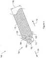
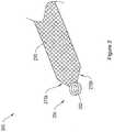


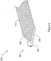

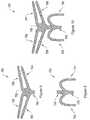

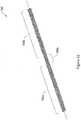
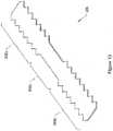


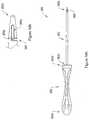

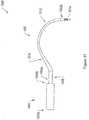


Classifications
- A—HUMAN NECESSITIES
- A61—MEDICAL OR VETERINARY SCIENCE; HYGIENE
- A61F—FILTERS IMPLANTABLE INTO BLOOD VESSELS; PROSTHESES; DEVICES PROVIDING PATENCY TO, OR PREVENTING COLLAPSING OF, TUBULAR STRUCTURES OF THE BODY, e.g. STENTS; ORTHOPAEDIC, NURSING OR CONTRACEPTIVE DEVICES; FOMENTATION; TREATMENT OR PROTECTION OF EYES OR EARS; BANDAGES, DRESSINGS OR ABSORBENT PADS; FIRST-AID KITS
- A61F2/00—Filters implantable into blood vessels; Prostheses, i.e. artificial substitutes or replacements for parts of the body; Appliances for connecting them with the body; Devices providing patency to, or preventing collapsing of, tubular structures of the body, e.g. stents
- A61F2/0004—Closure means for urethra or rectum, i.e. anti-incontinence devices or support slings against pelvic prolapse
- A61F2/0031—Closure means for urethra or rectum, i.e. anti-incontinence devices or support slings against pelvic prolapse for constricting the lumen; Support slings for the urethra
- A61F2/0036—Closure means for urethra or rectum, i.e. anti-incontinence devices or support slings against pelvic prolapse for constricting the lumen; Support slings for the urethra implantable
- A61F2/0045—Support slings
- A—HUMAN NECESSITIES
- A61—MEDICAL OR VETERINARY SCIENCE; HYGIENE
- A61B—DIAGNOSIS; SURGERY; IDENTIFICATION
- A61B17/00—Surgical instruments, devices or methods
- A61B17/04—Surgical instruments, devices or methods for suturing wounds; Holders or packages for needles or suture materials
- A61B17/0401—Suture anchors, buttons or pledgets, i.e. means for attaching sutures to bone, cartilage or soft tissue; Instruments for applying or removing suture anchors
- A—HUMAN NECESSITIES
- A61—MEDICAL OR VETERINARY SCIENCE; HYGIENE
- A61B—DIAGNOSIS; SURGERY; IDENTIFICATION
- A61B17/00—Surgical instruments, devices or methods
- A61B17/04—Surgical instruments, devices or methods for suturing wounds; Holders or packages for needles or suture materials
- A61B17/06—Needles ; Sutures; Needle-suture combinations; Holders or packages for needles or suture materials
- A61B17/06066—Needles, e.g. needle tip configurations
- A61B17/06109—Big needles, either gripped by hand or connectable to a handle
- A—HUMAN NECESSITIES
- A61—MEDICAL OR VETERINARY SCIENCE; HYGIENE
- A61F—FILTERS IMPLANTABLE INTO BLOOD VESSELS; PROSTHESES; DEVICES PROVIDING PATENCY TO, OR PREVENTING COLLAPSING OF, TUBULAR STRUCTURES OF THE BODY, e.g. STENTS; ORTHOPAEDIC, NURSING OR CONTRACEPTIVE DEVICES; FOMENTATION; TREATMENT OR PROTECTION OF EYES OR EARS; BANDAGES, DRESSINGS OR ABSORBENT PADS; FIRST-AID KITS
- A61F2/00—Filters implantable into blood vessels; Prostheses, i.e. artificial substitutes or replacements for parts of the body; Appliances for connecting them with the body; Devices providing patency to, or preventing collapsing of, tubular structures of the body, e.g. stents
- A61F2/0063—Implantable repair or support meshes, e.g. hernia meshes
- A—HUMAN NECESSITIES
- A61—MEDICAL OR VETERINARY SCIENCE; HYGIENE
- A61F—FILTERS IMPLANTABLE INTO BLOOD VESSELS; PROSTHESES; DEVICES PROVIDING PATENCY TO, OR PREVENTING COLLAPSING OF, TUBULAR STRUCTURES OF THE BODY, e.g. STENTS; ORTHOPAEDIC, NURSING OR CONTRACEPTIVE DEVICES; FOMENTATION; TREATMENT OR PROTECTION OF EYES OR EARS; BANDAGES, DRESSINGS OR ABSORBENT PADS; FIRST-AID KITS
- A61F2/00—Filters implantable into blood vessels; Prostheses, i.e. artificial substitutes or replacements for parts of the body; Appliances for connecting them with the body; Devices providing patency to, or preventing collapsing of, tubular structures of the body, e.g. stents
- A61F2/02—Prostheses implantable into the body
- A61F2/04—Hollow or tubular parts of organs, e.g. bladders, tracheae, bronchi or bile ducts
- A—HUMAN NECESSITIES
- A61—MEDICAL OR VETERINARY SCIENCE; HYGIENE
- A61B—DIAGNOSIS; SURGERY; IDENTIFICATION
- A61B17/00—Surgical instruments, devices or methods
- A61B2017/0046—Surgical instruments, devices or methods with a releasable handle; with handle and operating part separable
- A—HUMAN NECESSITIES
- A61—MEDICAL OR VETERINARY SCIENCE; HYGIENE
- A61B—DIAGNOSIS; SURGERY; IDENTIFICATION
- A61B17/00—Surgical instruments, devices or methods
- A61B2017/00743—Type of operation; Specification of treatment sites
- A61B2017/00805—Treatment of female stress urinary incontinence
- A—HUMAN NECESSITIES
- A61—MEDICAL OR VETERINARY SCIENCE; HYGIENE
- A61B—DIAGNOSIS; SURGERY; IDENTIFICATION
- A61B17/00—Surgical instruments, devices or methods
- A61B17/04—Surgical instruments, devices or methods for suturing wounds; Holders or packages for needles or suture materials
- A61B17/06—Needles ; Sutures; Needle-suture combinations; Holders or packages for needles or suture materials
- A61B17/06004—Means for attaching suture to needle
- A61B2017/06042—Means for attaching suture to needle located close to needle tip
- A—HUMAN NECESSITIES
- A61—MEDICAL OR VETERINARY SCIENCE; HYGIENE
- A61B—DIAGNOSIS; SURGERY; IDENTIFICATION
- A61B17/00—Surgical instruments, devices or methods
- A61B17/04—Surgical instruments, devices or methods for suturing wounds; Holders or packages for needles or suture materials
- A61B17/06—Needles ; Sutures; Needle-suture combinations; Holders or packages for needles or suture materials
- A61B17/06066—Needles, e.g. needle tip configurations
- A61B2017/06076—Needles, e.g. needle tip configurations helically or spirally coiled
- A—HUMAN NECESSITIES
- A61—MEDICAL OR VETERINARY SCIENCE; HYGIENE
- A61F—FILTERS IMPLANTABLE INTO BLOOD VESSELS; PROSTHESES; DEVICES PROVIDING PATENCY TO, OR PREVENTING COLLAPSING OF, TUBULAR STRUCTURES OF THE BODY, e.g. STENTS; ORTHOPAEDIC, NURSING OR CONTRACEPTIVE DEVICES; FOMENTATION; TREATMENT OR PROTECTION OF EYES OR EARS; BANDAGES, DRESSINGS OR ABSORBENT PADS; FIRST-AID KITS
- A61F2/00—Filters implantable into blood vessels; Prostheses, i.e. artificial substitutes or replacements for parts of the body; Appliances for connecting them with the body; Devices providing patency to, or preventing collapsing of, tubular structures of the body, e.g. stents
- A61F2/0063—Implantable repair or support meshes, e.g. hernia meshes
- A61F2002/0072—Delivery tools therefor
- A—HUMAN NECESSITIES
- A61—MEDICAL OR VETERINARY SCIENCE; HYGIENE
- A61F—FILTERS IMPLANTABLE INTO BLOOD VESSELS; PROSTHESES; DEVICES PROVIDING PATENCY TO, OR PREVENTING COLLAPSING OF, TUBULAR STRUCTURES OF THE BODY, e.g. STENTS; ORTHOPAEDIC, NURSING OR CONTRACEPTIVE DEVICES; FOMENTATION; TREATMENT OR PROTECTION OF EYES OR EARS; BANDAGES, DRESSINGS OR ABSORBENT PADS; FIRST-AID KITS
- A61F2220/00—Fixations or connections for prostheses classified in groups A61F2/00 - A61F2/26 or A61F2/82 or A61F9/00 or A61F11/00 or subgroups thereof
- A61F2220/0008—Fixation appliances for connecting prostheses to the body
- A—HUMAN NECESSITIES
- A61—MEDICAL OR VETERINARY SCIENCE; HYGIENE
- A61F—FILTERS IMPLANTABLE INTO BLOOD VESSELS; PROSTHESES; DEVICES PROVIDING PATENCY TO, OR PREVENTING COLLAPSING OF, TUBULAR STRUCTURES OF THE BODY, e.g. STENTS; ORTHOPAEDIC, NURSING OR CONTRACEPTIVE DEVICES; FOMENTATION; TREATMENT OR PROTECTION OF EYES OR EARS; BANDAGES, DRESSINGS OR ABSORBENT PADS; FIRST-AID KITS
- A61F2230/00—Geometry of prostheses classified in groups A61F2/00 - A61F2/26 or A61F2/82 or A61F9/00 or A61F11/00 or subgroups thereof
- A61F2230/0002—Two-dimensional shapes, e.g. cross-sections
- A61F2230/0004—Rounded shapes, e.g. with rounded corners
Definitions
- Pelvic floor disordersafflict many women. According to some studies, about 1out of 11 women need surgery for a pelvic floor disorder during her lifetime.
- the pelvic floorgenerally includes muscles, ligaments, and tissues that collectively act to support anatomical structures of the pelvic region, including the uterus, the rectum, the bladder, and the vagina.
- Pelvic floor disordersinclude vaginal prolapse, vaginal hernia, cystocele, rectocele, and enterocele. Such disorders are characterized in that the muscles, liganlents and/or tissues are damaged, stretched, or otherwise weakened, which causes the pelvic anatomical structures to fall or shift and protrude into each other or other anatomical structures.
- UIurinary incontinence
- SIDstress urinary incontinence
- hypermobilityhypermobility
- ISDthe urinary sphincter valve, located within the urethra, fails to close (or "coapt") properly, causing urine to leak out of the urethra during stressful activity.
- the pelvic floorIn hypermobility, the pelvic floor is distended, weakened, or damaged, resulting in increases in intra-abdominal pressure (e.g., due to sneezing, coughing, straining, etc.) and consequently the bladder neck and proximal urethra rotate and descend. As a result, the urethra does not close with sufficient response time, and urine leaks through the urethra.
- intra-abdominal pressuree.g., due to sneezing, coughing, straining, etc.
- UI and pelvic floor disorderswhich are usually accompanied by significant pain and discomfort, are typically treated by implanting a supportive sling in or near the pelvic floor region to support the fallen or shifted anatomical structures or to, more generally, strengthen the pelvic region by, for example, promoting tissue ingrowth.
- treatments of stress incontinenceare made without treating the pelvic floor disorders at all, potentially leading to an early recurrence of the pelvic floor disorder.
- Existing devices, methods, and kits for treatmenttypically apply delivery devices to position a supportive sling into a desired position in the pelvic region by pushing or pulling the sling through the surrounding tissue.
- delivery devicesWhen treating pelvic floor disorders and UI it is often desirable to use a tanged mesh implant material, or to use an implant with anchoring projections along an edge of the material.
- the tangs and projectionsmay irritate the tissue if rubbed against it during implantation.
- the tangs of the implantmay make it difficult to adjust the positioning or tension of the implant during delivery. If the implant is protected by a sleeve during delivery, extra steps are needed to separate the sleeve from the implant and remove it from the body. Accordingly, medical operators and patients need improved systems, methods, and surgical kits for the treatment of pelvic floor disorders and/or urinary incontinence with minimal irritation of the patient's tissue.
- WO 2004/016196discloses a system for delivering an implant to a patient comprising an implant having an attachment strap, an end termination member attached to the strap, a shaft having a slot located at a distal end for associating with an end termination member of the implant, and a sheath having a hollow center adapted to allow the shaft to extend therethrough.
- US 2005/131393 A1discusses implant delivery systems including systems comprising a delivery device, a sling, guide members and connectors which interconnect the above.
- the disclosureaddresses the deficiencies of the prior art by providing an improved implant delivery system. More particularly, in various aspects, the disclosure provides an implant with an attachment strap and a sheath for use in delivering the implant to patient tissue.
- the disclosureprovides a system for delivering an implant to a patient for the treatment of pelvic floor disorders such as cystocele, rectocele, vaginal prolapse, and other similar disorders.
- An exemplary systemincludes an implant having an attachment strap, an end termination member attached to the strap, and one or more soft tissue anchors attached to the implant.
- the systemalso includes a shaft having a slot located at a distal end for associating with the end termination member of the implant, and a sheath having a hollow center adapted to allow the shaft to extend therethrough.
- the slot in the shaftis L-shaped.
- the exemplary systemfurther includes a handle coupled to the shaft.
- the systemmay also include a handle coupled to the sheath.
- the handleis removable.
- the one or more soft tissue anchorsincludes one or more tangs on the implant strap.
- the end termination membermay be one or more of the soft tissue anchor(s).
- the end termination membermay be a loop or a ring.
- the end termination membermay have at least one radially extending leg, and may have two radially extending legs.
- At least one of the shaft and the sheathis substantially straight, or at least one of the shaft and the sheath has a curved shape.
- the shaftis rigid and the sheath is flexible.
- the sheathis rigid and the shaft is flexible.
- the sheathis curved and the shaft is flexible material, and the shaft bends to extend through the center of the sheath upon insertion.
- the shaftis longer than the sheath.
- a tipis attached to a distal end of the sheath.
- the implanthas two arms and a posterior extension portion and is adapted to be positioned under a posterior pelvic region.
- the two armsmay arch in a posterior direction, toward the posterior pelvic region.
- the implanthas four arms and is adapted to be positioned under an anterior pelvic region.
- the armsmay extend laterally from the center of the implant and in an anterior direction, toward the anterior pelvic region.
- the implanthas six arms and is adapted to be positioned under the pelvic region. Two of the arms may arch in a posterior direction, toward the posterior pelvic region, and four of the arms may extend laterally from the center of the implant and in an anterior direction, toward the anterior pelvic region.
- the implanthas a tanged first edge.
- the implantmay include a pattern of projections.
- the disclosurealso provides a method for delivering an implant to a patient including inserting a sheath having a hollow center into an incision in the patient, inserting a shaft of a delivery device into the center of the sheath, associating an end termination member of the implant with the slot, advancing the shaft and the associated implant through the sheath, and anchoring the implant in the patient's pelvic floor region.
- the shaftpulls the end termination member through the sheath. In another implementation, the shaft pushes the end termination member through the sheath.
- the shaftmay be advanced into the sheath prior to advancing the sheath into the incision. According to one feature, the end termination member is removed from the implant after it has been advanced through the sheath.
- the shaftis advanced into the sheath prior to advancing the sheath into the incision.
- the shaftmay be removed from the sheath, pulling the end termination member through the sheath.
- An arm of the implantmay also be pulled through the sheath.
- the sheathmay be removed from the patient, leaving the implant anchored in patient tissue.
- the implantis anchored in patient tissue through one or more tangs on the implant.
- the end termination memberanchors in patient tissue.
- the sheathis inserted through the patient's gluteus maximus.
- the sheathmay also be inserted through the sacrospinous ligament.
- the disclosurein one illustrative embodi-ment, relates to systems and methods for delivering and placing a medical implant at an anatomical site in the body of a mammal.
- the disclosureprovides delivery devices, systems, and methods for placing an implant, e.g., a pelvic floor support mesh.
- the implantincludes a supportive pelvic floor mesh having end termination members, which act as soft tissue anchors, for use in sling delivery.
- the implantis delivered to the pelvic floor region, which may include the periurethral and other retropubic tissue.
- Delivery approachesmay include a transobturator approach (inside-out or outside-in), a suprapubic approach, a pre-pubic approach, a retropubic approach, a transabdominal approach, and any combination of approaches.
- the systemincludes a sheath having a hollow center and a delivery device having a shaft.
- the shaftmay be inserted through the sheath, attached to an end termination member, and used to advance the end termination member and the associated implant through the sheath.
- the patientmay be either a female patient or a male patient.
- Figure 1shows a sling assembly 100 including an exemplary implant end termination member 104 attached to the arm of a mesh implant 110.
- the end termination member 104includes a ring 102, a first arm 106, and a second arm 108.
- the arms 106 and 108extend radially from the ring 102.
- the end termination member 104is a soft tissue anchor.
- the ring 102may be sized and shaped to engage with a delivery device, such as, without limitation, the distal end of a shaft or needle of the delivery devices 950, 970, and 1000 described below with respect to Figures 19A-19B , 20A-20B , and 21 .
- an operatorcouples the ring 102 to a slot in the shaft of a delivery device, such as the L-slot 960 of Figure 19B , for implantation into a patient, as will be discussed in further detail below with respect to Figures 19A and 19B .
- a delivery devicesuch as the L-slot 960 of Figure 19B
- an operatorplaces the ring 102 over the tip of a delivery device shaft and slides the ring 102 down the tip until the ring 102 abuts against a step, shoulder, or other stopping mechanism, as will be discussed in further detail below with respect to Figures 20A and 20B .
- the ring 102includes an inner surface 102a that, in certain embodiments, is tapered to inter-fit with the tip of a delivery device.
- the ring 102 and arms 106 and 108 of the end termination member 104are coplanar with the implant 110.
- the implant assembly 100has a low delivery profile.
- the delivery profilerefers to the maximum cross-sectional area of a passageway through the patient's anatomy that is required for placement of the implant, and smaller delivery profiles may be beneficial at least in part because they may reduce tissue damage during implant delivery.
- the end termination member 104is flexible, such that the ring 102 and arms 106 and 108 may be arranged in a non-coplanar position.
- the ring 102may be any shape, including square, triangular, oval, or other preferred shapes.
- the ring 102may also be any size, and in particular may be configured to couple with shafts or needles of varying dimensions.
- the arms 106 and 108may be sized and shaped to engage with and attach to the implant 110.
- the arms 106 and 108 of the end termination member 104extend radially from the ring 102 and adjoin at an angle 112, forming a V-shape.
- the end termination member 104is flexible such that the angle 112 can be increased or decreased upon application of appropriate mechanical pressure.
- the angle 120 formed between the arms 106 and 108may also vary. For example, the arm 106 and 108 may be squeezed together, reducing the angle 120 to about zero degrees.
- the arms 106 and 108interact with the tissue or with the sides of the sheath to increase the angle 112 and decrease the angle 120, as the arms 106 and 108 are pushed together.
- the arms 106 and 108may interact with the tissue to decrease the angle 112 and increase the angle 120, as the arms 106 and 108 are pushed apart.
- the varying angles 112 and 120facilitate movement of the implant assembly 100 in the forward direction 114, and impedes movement of the mesh strap 110 in the retrograde direction 118.
- the angle 112may vary from between about 0 degrees to about 90 degrees, and in other embodiments, the angle 112 may vary to more than about 90 degrees.
- the angle 120may vary from between about 0 degrees to about 110 degrees, and in other embodiments, the angle 120 may vary to more than about 110 degrees.
- the flexibility of the end termination member 104may vary. The flexibility of the end termination 104 and the measurement of the angles 112 and 120 are generally chosen to suit the particular delivery path and location for anchoring the implant, as well as the condition being treated.
- the V-shaped configuration of the arms 106 and 108acts to engage with patient tissue to resist removal once the implant assembly 100 is implanted.
- the depicted arms 106 and 108extend beyond the width 110a of the mesh implant 110 to provide additional engagement with tissue, but in other illustrative embodiments, the arms 106 and 108 may have any length, and may not extend beyond the width 110a of the implant 110. In one embodiment, the distance between the arms 106 and 108 is less than the width of the implant 110, such that the arms 106 and 108 do not extend to the edge of the implant 110.
- the end termination member 104may be molded to the implant 110, as described in further detail in U.S. Patent Application “Systems, Devices, and Methods for Treating Pelvic Floor Disorders," Serial No. 11/400,111, filed April 6, 2006 .
- the end termination member 104may include two pieces: a top piece, and a bottom piece. According to this embodiment, the two pieces may be snapped together to attach the end termination member 104 to the implant 110.
- Figure 2shows an implant assembly 200 including an end termination member 204 and a mesh implant 210.
- the end termination member 204includes a ring 202, and does not include radially extending legs.
- a manufacturermay affix the end termination member 204 to the implant 210 using any of the methods described above.
- the manufacturerhas trimmed comers of the implant 210 at locations 210a and 210b.
- the comers of the implantmay not be trimmed, or the comers may be trimmed to any suitable shape, including round, triangular, and square.
- Figure 3shows another embodiment of an implant assembly 300 including end termination member 304 and mesh implant 310.
- the end termination member 304lies substantially coplanar with the implant 310, and includes a tab-shaped region 308 and an aperture 302.
- the aperture 302may be sized and shaped to couple with the shaft of a delivery device.
- the aperture 302is sized, shaped and positioned in the tab region 308 to couple with the slot in the end of the shaft of a delivery device, such as the L-slot 960 shown in Figure 19B .
- the aperture 302is small (i.e., it has a diameter of less than about 2mm), and is sized to couple with the narrow needle of a delivery device.
- the aperture 302is sized to allow an operator to thread a filament therethrough.
- the filamentmay couple to a separate soft tissue anchor as described in connection with other embodiments herein.
- a manufacturerdips the implant 466 in a curable plastic to form the end termination member 304. The manufacturer then trims the plastic to create the tab shape and punches a hole through the plastic to create the aperture 302.
- the manufacturermay pre-form the end termination member 304 and subsequently snap-fit, glue, stitch, or otherwise attach it to the implant 310. Additional embodiments of the end termination member 304 are described in the above reference "Systems, Devices, and Methods for Treating Pelvic Floor Disorders.”.
- Figure 4is a longitudinal cross sectional view of a sling assembly 400 including and end termination member 404 and an implant 410.
- the end termination member 404includes an association loop 402 and a dilator 406.
- the dilator 406is a rigid polymer tube of approximately 2 cm in length terminating in a conical tip. Embedded and secured along the length of the dilator 406 are two ends of a wire 408, which may be formed from twisted metal strands.
- the wire 408extends from the conical tip of the dilator 406 to form an association loop 402.
- the association loop 402extends approximately 15 mm from the end of the conical tip of the dilator 406.
- the association loopextends any suitable distance from the conical tip of the dilator 406, including about 5 mm, about 10 mm, about 20 mm, about 25 mm, about 30 mm, about 35 mm, about 40 mm, about 50 mm, about 75 mm, about 1 cm, and more than 1 cm.
- the association loop 402is preferably deformable, but generally shape-retaining.
- the shape of the association loop 402may be changed by outside pressure, but the association loop 402 will return to its original shape upon release of the outside pressure.
- the association loop 402 of the end termination member 404is sized and shaped for coupling to a slot in the end of a shaft of a delivery device, such as the L-slot 960 of delivery device 950 shown in Figures 19A and 19B .
- Figure 5Ashows an implant assembly 500, including an end termination member 504 and a mesh implant 510.
- the end termination member 504includes a ring 502 and a dilator 508.
- the dilator 508may also act as a soft tissue anchor.
- the ring 502threads through apertures 514 and 516 in a first shoulder region 512 of the dilator 508. More particularly, the ring 502 couples with dilator 508 by threading through apertures 514 and 516, and couples with the mesh implant 510 by threading through apertures 518 and 520 in the mesh implant 510.
- the ring 502is constructed of a rigid or semi-rigid material, and maintains its shape. In another embodiment, the ring 502 is constructed of a deformable material that is shape retaining.
- the ring 502is flexible, and may be constructed from an elastic material.
- the ring 502stretches to absorb lateral stresses.
- Woven surgical implantsmay stretch and damage due to stresses during delivery of the implant, and stretching of the ring 502 may help prevent stretching and damage to the implant 510 during delivery.
- elastic ringsadjust to short term and/or long term changes in the patient's changing anatomy to prevent damage to the surgical implant 510. For example, when the patient sneezes, coughs, or jumps, muscles in the pelvic region can contract and anatomical structures may shift. Anatomical structures may also shift over long periods of time because of the patient's changing anatomy due to, for example, weight gain or weight loss. In such cases, elastic rings stretch to absorb the stresses caused by these short-term and long-term changes, thereby preventing the changes from damaging the surgical implant 510.
- the ring 502is sized and shaped to couple with the shaft of a delivery device.
- the ring 502couples with a slot in the end of the shaft of a delivery device, such as the L-slot 960 of delivery device 950 shown in Figures 19A and 19B .
- Figure 6shows an implant assembly 600 including an end termination member 604 and a mesh strap 610.
- the end termination member 604includes arms 606 and 608 and a ring 602 that has a circular cross-section lying in a plane that is perpendicular to a plane of the mesh strap.
- the end termination member 604couples to the end of the shaft of a delivery device, such as the delivery device 970 described below with respect to Figures 20A and 20B .
- the orientation of the ring 602 with respect to the end termination member 604as compared with the ring 102 with respect to the end termination member 104 of Figure 1 , results in a different orientation of the mesh implant 610 with respect to the delivery device when the mesh implant and the device are coupled.
- This alternative orientationresults in the implant 610 aligning with the tip of the shaft, as opposed to extending from the shaft tip at about a 90 degree angle.
- the alternative orientation using end termination member 604may be preferred by a medical operator when the operator is delivering the mesh implant 610 through a narrow anatomical incision, through a narrow pathway in a patient's anatomy, and/or through a sheath.
- FIG 7shows a soft tissue anchor 700, which may be attached to the arm of an implant, such as implants 730, 750, and 780 shown in Figures 8, 9, and 10 , and described below.
- the soft tissue anchor 700includes a center portion 702, and tabbed projections 704, 706, 708, 710, 712, and 714. Additional projections may be present on the reverse side (not shown) of the anchor 700.
- the center portion 702 of the anchor 700may be solid or hollow. In one embodiment, the center portion 702 includes a through-aperture 718.
- the soft tissue anchor 702may be adapted to interfit with the shaft of a delivery device, such as the shaft 972 of the delivery device 970, shown in Figures 20A and 20B , and discussed below.
- Figure 8shows a mesh implant 730 including two arms 732 and 734, and a posterior extension portion 738.
- the implant 730is adapted to be positioned under a posterior pelvic region, and may provide posterior pelvic floor support.
- the two armsarch in a posterior direction, toward the posterior pelvic region.
- the mesh implant 730may also include an anteriorly extending portion 740.
- any of the end termination members 104, 204, 304, 404, 504, and 604may be attached to the arms 732 and 734 of the implant 730.
- any of the end termination members 104, 204, 304, 404, 504 and 604may be attached to the posterior extension portion 738.
- a combination of various end termination membersmay be used.
- the arms 732 and 734may be tanged, similar to the arms 840a and 840b of Figure 12 .
- Figure 9shows a mesh implant 750 including four arms 752, 754, 756, and 758 and a posterior extension portion 760.
- the implant 750is adapted to be positioned under an anterior pelvic region, and may provide anterior pelvic floor support.
- the arms 752, 754, 756, and 758extend laterally from the center 762 of the implant 750 and in an anterior direction, toward the anterior pelvic region.
- any of the end termination members 104, 204, 304, 404, 504, and 604may be attached to the arms 752, 754, 756, and 758 of the implant 750.
- a combination of various end termination membersmay be used.
- the arms 752, 754, 756, and 758may be tanged, similar to the arms 840a and 840b of Figure 12 .
- Figure 10shows a mesh implant 780 including six arms 782, 784, 786, 788, 790, and 792 and a tail 794.
- the implant 780is adapted to be positioned under the pelvic region, and may provide pelvic floor support.
- two arms 782 and 784 of the implant 780arch in a posterior direction, toward the posterior pelvic region, while four arms 786, 788, 790, and 792 extend laterally from the center 798 of the implant and in an anterior direction, toward the anterior pelvic region.
- any of the end termination members 104, 204, 304, 404, 504, and 604may be attached to the arms 782, 784, 786, 788, 790, and 792 of the implant 780.
- a combination of the various end termination membersmay be used.
- the arms 782, 784, 786, 788, 790, and 792may be tanged, similar to the arms 840a and 840b of Figure 12 .
- Figure 11shows a mesh implant 800 including six arms 802, 804, 806, 808, 810, and 812, having end termination members 822, 824, 826, 828, 830, and 832, respectively. While the end termination members 822, 824, 826, 828, 830, and 832 are depicted as being similar to the end termination member 104 of Figure 1 , the end termination members 822, 824, 826, 828, 830, and 832 may include any of the end termination members 104, 204, 304, 404, 504, and 604, or any combination of end termination members 104, 204, 304, 404, 504, and 604.
- Figure 12shows an exemplary mesh implant 840 having two end portions 840a and 840b and a center portion 840c. As shown in Figure 12 , the end portions 840a and 840b have tanged edges, which help to anchor the mesh implant following implantation. The center portion 840c has smooth non-tanged edges, which may help prevent irritation of the supported tissue or organ.
- Figure 13shows an exemplary implant 850 having two end portions 850a and 850b and a center portion 850c.
- the end portions 850a and 850bcomprise a pattern of projections along their lateral edges, which help to anchor the implant in patient tissue upon implantation.
- the center portion 850chad smooth edges with no projections, which may help prevent irritation of the supported tissue or organ.
- the arms of an implantare the attachment straps of the implant.
- the attachment strapsform a continuum with the center portion of the implant, and may include one or more non-tanged portions.
- the implantsare inserted into a patient by the use of a sheath.
- Figures 14-16 , 17A and 18Aare side-views of various exemplary sheathes for such use.
- the sheathesare hollow, to allow for passage of a shaft therethrough.
- Figure 14depicts a sheath 860 having a proximal end 860a, a distal end 860b, and a straight portion 864 extending from the proximal end 860a to the distal end 860b of the sheath 860.
- Figure 15depicts a sheath 870 having a proximal end 870a and a distal end 870b.
- the sheath 870includes a straight portion 874 extending from the proximal end 870a of the sheath 870, and a curved portion 876 extending from the straight portion 874 to the distal end 870b of the sheath 870.
- Figure 16depicts a side view of a sheath 880 having a proximal end 880a and a distal end 880b.
- the sheath 880includes a straight portion 884 extending from the proximal end of the sheath 880, an upward-curving portion 886, extending from the distal end of the straight portion 884, and a downward-curving portion 888, extending from the distal end of the upward-curving portion 886 to the distal end 880b of the sheath 880.
- the sheathes shown in Figures 14-16all lie substantially in one plane.
- Figure 17Adepicts a side view of a sheath 900 for use in delivering an implant to patient tissue
- Figure 17Bdepicts a top view of the sheath 900.
- the sheath 900has a proximal end 900a and a distal end 900b.
- the sheath 900includes a first straight portion 904, a second straight portion 906, a curved portion 908, and a third straight portion 910.
- the sheath 900further includes a removable tip 912.
- the first straight portion 904extends distally away from the proximal end 900a of the sheath 900 along a longitudinal axis 916.
- the second straight portion 906extends distally from, but at an angle to the first straight portion 904.
- the second straight portion 906is substantially coplanar in a first plane with the first straight portion 904.
- the first curved portion 908 of the sheath 900extends from a distal end of the second straight portion 906 and curves the sheath 900 back toward the axis 916.
- the third straight portion 910 of the sheath 900extends from a distal end of the first curved portion 908, as shown in Figure 17B .
- the first curved portion 908 and the third straight portion 910are substantially coplanar with each other in a second plane. As depicted in Figure 17B , the curved section 908 defines a substantially constant radius curve.
- the optional conical tip 912 of the sheath 900may attach to the distal end 900b of the sheath 900.
- the conical tip 912may be configured for percutaneous punctuation and/or advancement through tissue.
- the tip 912may be blunt or sharp.
- a blunt tipprovides some resistance to unintended penetration through tissue or organ, such as the bladder.
- Figure 18Adepicts a side-view of a sheath 930 configured as a variation of the illustrative sheath 900 of Figure 17A.
- Figure 18Bdepicts a top-view of the sheath 930.
- the sheath 930has a proximal end 930a and a distal end 930b. Similar to sheath 900, sheath 930 includes a straight portion 934 extending distally away from the proximal end 930a of the sheath 930 along a longitudinal axis 946, and a second straight portion 936 extending distally from, but at an angle to the first straight portion 934, and substantially coplanar in a first plane with the first straight portion 934.
- the sheath 930further includes a first curved portion 938 extending from a distal end of the second straight portion 936 and curving the sheath 930 back toward the axis 946.
- a third straight portion 940 of the sheath 930extends from a distal end of the first curved portion 938, as shown in Figure 18B .
- the sheath portions 934, 936, and 938are arranged such that the angle between the plane of the first 934 and second 936 straight portions and the plane of the curved portion 938 are substantially orthogonal to each other.
- the sheath 930may also include a removable tip, such as tip the 912, at the distal end 930b.
- a handlemay be associated with any of the sheathes of Figures 14-16 , 17A-17B, and 18A-18B during insertion, and the handle may extend over a portion of or the entirety of the first straight portion.
- the distal straight portion and the curved portionsare the only parts of the sheath that penetrate into a patient's body.
- a hub containing medicationmay be inserted into the proximal end of any of the sheathes of Figures 14-16 , 17A-17B, and 18A-18B .
- the sheathes 860, 870, 880, 900, and 930may be formed from a metal or a polymeric material.
- suitable metalsinclude, but are not limited to, stainless steel, titanium, and alloys such as nitinol.
- Suitable polymers, which can be used as a coating on a metal to form the sheathinclude but are not limited to, plastics such as polytetrafluoroethylene (PTFE).
- PTFEpolytetrafluoroethylene
- the sheathis rigid. However, in other configurations, the sheath is flexible.
- the surface of the sheathis smooth and may be coated with one or more drugs such as anesthetic, anti-inflammatory, coagulating, anticoagulating, antibiotic, or antimicrobial agents.
- the drugmay be delivered to the patient's tissue while the sheath is in contact with the tissue.
- the surface of the sheathmay be coated with a light-absorbing coating to reduce glare, for example, under a cystoscope.
- the coatingmay be a polymer, such as Teflon, or other suitable material, and may be colored to aid in detection.
- the surface of the sheathmay be painted so that one can easily tell it apart from surrounding tissue and fluid under a cystoscope to make it easier to detect under the cystoscope.
- the sheathmay be at least partly hollow, and it may include a lumen (not shown) that has one or more openings on the sheath, for example, at the distal tip or along the side of the shaft.
- the cross-section of the sheathmay have a constant shape and size, or its shape and/or size may vary along its length.
- the cross-section of the sheathmay assume any suitable shape, for example, circular, semi-circular, oval, triangular, or rectangular.
- the distal endmay include an enlarged, flared portion to dilate tissue beyond the nominal diameter of the sheath.
- Figures 19A-19B , 20A-20B , and 21are side-views of various delivery devices for use in delivering an implant to patient tissue.
- Figure 19Ashows a delivery device 950 having a straight shaft 952 and a handle 954.
- the handle 954is optional, and the shaft 952 may be used without the handle 954.
- the handlehas a proximal end 954a and a distal end 954b, and the shaft 952 has a proximal end 952a and a distal end 952b.
- the proximal end 952a of the shaft 952extends from the distal end 954b of the handle 954.
- the distal end 952b of the shaft 952includes an L-slot 960, as shown enlarged in Figure 19B .
- Figure 19Bis a side view of an L-slot 960 on a distal end 952b of a shaft 952 of a delivery device 950.
- the L-slot 960is preferably formed from a first channel 960a approximately 2 mm in length and 1 mm in width extending radially into the shaft 952 and a second channel 960b approximately 5 mm in length and 1 mm in width extending distally along the length of the distal end 952b of the shaft 952 from an inner terminal end of the first channel 960a.
- an end termination memberslides radially into the first channel 960a and along the second channel 960b to hook one end of an implant onto the distal end 952b of the shaft 952 of a delivery device 950.
- L-slot 960 configurationAn advantage of the L-slot 960 configuration is that the delivery device 950 may be used to pull an implant into place.
- the distally extending orientation of the second channel 960bcauses an associated end termination, such as end termination member 104, to slide to the distal most position in the L-slot 960. This tends to maintain the association between the end termination, and thus the implant, and the shaft 952, keeping the end termination member hooked into the second channel 960b during withdrawal of the delivery device. Additionally, the end termination member remains free to slide along the second channels 960b. When slid to a proximal-most position in the second channel 960b, the end termination member may be slid radially out of the first channel 960a to unhook the implant from the delivery device(s) with minimal effort.
- the shaft 952is inserted into a sheath, such as the sheath 860 of Figure 14 , and an end termination member of an implant is attached to the L-slot 960, allowing a user to drag the end termination member and the associated arm of an implant into the sheath by pulling the shaft 952 back out of the sheath.
- a sheathsuch as the sheath 860 of Figure 14
- an end termination member of an implantis attached to the L-slot 960
- This processmay be repeated with another end termination member on another arm of the implant, such as implant 780 shown in Figure 10 , using the same or a second delivery device.
- the second channel 960b of an L-slot 960extends proximally, rather than distally, along the distal end of a shaft of any delivery device of the disclosure, and the shaft is used to push implant through the sheath.
- the proximally extending orientation of the second channelcauses the end termination, for example the end termination member 104 as depicted in Figure 1 , to slide to a proximal most position in the L-slot. This tends to maintain the end termination, and thus the sling assembly comprising the end termination, hooked onto the second channel during insertion of the shaft of the delivery device into the sheath.
- FIG. 20AAn alternative delivery device 970 for pushing an implant through a sheath, is shown in Figure 20A .
- the delivery device 970having a shaft 972 and a handle 974.
- the handle 974is optional, and the shaft 972 may be used without the handle 974.
- the handlehas a proximal end 974a and a distal end 974b, and the shaft 972 has a proximal end 972a and a distal end 972b.
- the shaft 972includes a straight portion 978, extending from the distal end 974b of the handle 974, and a curved portion 980 extending from the distal end of the straight portion 978 to the distal end of the shaft 972b.
- the distal end 972b of the shaft 972includes a reduced-diameter tip portion 984, as shown enlarged in Figure 20B .
- Figure 20Bshows an enlarged side view of the distal end 972b of the shaft 972 of Figure 20A .
- the distal end 972b of the shaft 972, as shown in Figure 20Bincludes part of the curved portion 980, shoulder 988, and a reduced diameter tip-portion 984.
- the shaft 972may couple with an end termination, such as end termination member 104 of Figure 1 or end termination member 604 of Figure 6 , such that the ring of the end termination member slides down the tip-portion 984 until the ring abuts the shoulder 988.
- the shoulder 988prevents passage of the ring of an end termination member past the reduced-diameter tip 984.
- the tip-portion 984has a constant cross-section.
- the cross-section of the tip-portiontapers toward the distal end.
- the tip-portionmay be formed to interfit with an end termination member including a ring with a tapered inner surface.
- Figure 21depicts a side view of a delivery device 1000 including a shaft 1002 and a handle 1004.
- the handle 1004is optional, and the shaft 1002 may be used in operation without the handle 1004.
- the handle 1004has a proximal end 1004a and a distal end 1004b.
- the shaft 1002extends from the distal end 1004b of the handle 1004, and has a proximal end 1002a and a distal end 1002b.
- the shaft 1002includes a straight portion 1008 extending from the distal end of the handle 1004b, an upward-curving portion 1010, extending from the distal end of the straight portion 1008, and a downward-curving portion 1012, extending from the distal end of the upward-curving portion 1010 to the distal end 1002b of the shaft 1002.
- the distal end 1002b of the shaftincludes an L-slot 1014, similar to the L-slot 960 shown enlarged in Figure 19B .
- the distal ends 952b, 972b, and 1002b of the shafts 952, 972, and 1002 of Figures 19A , 20A , and 21may include any type of tip, including the L-slot 960 and the reduced-diameter tip 984 of Figures 19B and 20B , respectively.
- the shafts 952, 972, and 1002may be attached to any type of handle, including for example, handles 954, 974, and 1004 of Figures 19A , 20A , and 21 .
- the shafts 952, 972, and 1002may be used during an operative procedure without an associated handle.
- the shafts 952, 972, and 1002 shown in Figures 19A , 20A , and 21all lie substantially in one plane.
- the shafts 952, 972, and 1002are inserted into associated sheathes, and used to pull or push an end termination member and associated implant arm through the sheath.
- the sheathes and/or the shaftsmay be flexible, to allow a shaft, such as shafts 952, 972, and 1002 to pass through a sheath, such as sheathes 860, 870, 880, 900, and 930.
- Further delivery devices not shown herein,may include shafts shaped similarly to the sheathes 900 and 930 shown in Figures 17A and 18A , respectively.
- Figures 22shows aspects of an exemplary transobturator procedure 1050 for placement of an implant 1052 in patient tissue.
- the exemplary implantincludes end termination members 1062 and 1066, similar to the end termination member 104 of Figure 1 .
- the end termination members 1062 and 1066may be any suitable end termination members, such as end termination member 204 of Figure 2 , or end terminations 304, 404, 504, or 604 described above.
- Figure 23shows a similar procedure 1080 for placement of an implant 1082, similar to implant 780 of Figure 10 .
- the exemplary implant 1082includes end termination members 1084, 1086, 1088, 1090, 1092, and 1094.
- the implants 1052 and 1082may include tanged mesh attachment straps, similar to the implant 840 of Figure 12 .
- the patientis placed on an operating table in a position to provide access to the pelvic region.
- the operatormay subject the patient to local anesthesia, regional anesthesia, and/or general anesthesia or sedation according to his preference.
- the operatormakes a transverse incision (not shown) in the anterior vaginal wall of the patient and dissects the incision bilaterally according to his preference using, for example, surgical scissors.
- the operatordissects bilaterally to the inferior pubic ramus on both sides of the patient.
- the incisionmay be made in the vagina so as to allow the inserted shaft to be near, contact, apply pressure to, or poke the skin at a position that is generally in line with the urethral meatus.
- the operatormakes a vertical skin incision in the groin, large enough to insert the tip of the sheath just lateral to the edge of the inferior pubic ramus at the junction where the inferior pubic ramus and the adductor longus muscle meet. This may be repeated on the contralateral side.
- the operatoraccesses the patient's pelvic region via the two incisions to insert the implant into the patient's pelvic region and secure the implant within the region so that at least a portion of the implant is located posterior to the bladderneck.
- the operatorinserts the sheath 1054 through a vertical skin incision, piercing through the obturator muscle and obturator membrane, toward the vaginal wall. The operator may hear and/or feel a pop indicating that he has pierced the obturator membrane.
- the distal end of the sheath 1054may include a tip, such as tip 912 of Figure 17B , and the proximal end of the sheath 1054 may be removably coupled to a handle, such as handles 954, 974, and 1004 of Figures 19 , 20 , and 21 .
- the operatormay turn the handle at a 45° angle medial toward the midline, and place the opposite hands forefinger into the lateral dissection of the vaginal incision, placing the fingertip on the distal end of the sheath 1054.
- the operatoruses his fingertip to guide the distal end of the sheath around the inferior pubic ramus and through the vaginal incision, maintaining contact with the finger.
- the operatormay palpate during delivery as preferred.
- the operatormay also use the posterior portion of the patient's pubic bone as an anatomical landmark to assist in guiding the needle.
- the optional tip and handlemay be removed from the sheath 1054.
- a shaft 1060is inserted into the sheath 1054, such that the distal end of the shaft 1060, including the L-slot 1064, extends past the distal end of the sheath 1054.
- the shaft 1060is flexible, easing insertion of the shaft 1060 into the sheath 1054.
- the shaft 1060is inserted into the sheath 1054 before the sheath 1054 is inserted into patient tissue, and the shaft-sheath combination is inserted into the patient in a transobturator method as described above, such that the distal end of the sheath 1054 exits the tissue through the vaginal incision.
- the sheath 1054maybe flexible and the shaft 1060 may be rigid.
- the sheathis inserted via an inside-out method.
- the sheathis inserted first through the vaginal incision, then through the obturator foramen and toward the vertical skin incision.
- the shaftmay then be inserted into the sheath via the outside-in method (toward the vaginal incision), as described above.
- the distal end of the shaft 1060includes an L-slot 1064, similar to the L-slot 960 shown in Figure 19B .
- the L-slot 1064extends beyond the distal end of the sheath 1054.
- the operatorthen hooks the end termination member 1062 of the implant 1052 on to the L-slot 1064, to couple the implant 1052 to the shaft 1060.
- the operatorremoves the shaft 1060 from the sheath 1054, for example by pulling handle 1058, thereby advancing the arm 1068 of the implant 1052 through the sheath 1054.
- the arms of the end termination member 1062may be squeezed together to allow the end termination member 1062 to fit into and advance through the sheath 1054.
- the end termination member 1062 of the implant 1052is uncoupled from the shaft 1060, by sliding the ring of the end termination member 1062 out of the L-slot 1064.
- the arm 1068includes anchoring tangs or projections as shown in the implants 840 and 850 of Figures 12 and 13 , and the end termination member 1062 is removed (e.g., cut off) from the arm 1068.
- the sheath 1054may then be removed from the patient, by pulling the proximal end of the sheath, leaving the arm 1068 of the implant 1052 in place.
- thisallows for implantation of a tanged mesh implant, such as implant 840 of Figure 12 , or an implant with lateral projections, such as implant 850 of Figure 13 , without unnecessary irritation of patient tissue such as may be caused by advancing a rough edge across patient tissue.
- the tangs or projectionsmay act as a soft tissue anchor to anchor the arm in patient tissue. The operator repeats this process for the other end termination member 1066, inserting it on the contralateral side of the patient.
- Figure 23shows aspects of an exemplary transobturator procedure 1080 for placement of an implant 1082 in patient tissue.
- the exemplary implant 1082is substantially the same as the implant 780 shown in Figure 10 .
- the implant 1082includes arms 1104, 1106, 1108, 1110, 1112, and 1114, and a posterior extension portion 1116. Attached to the distal end of each arm 1104, 1106, 1108, 1110, 1112, and 1114 of the implant 1082, is an end termination member 1084, 1086, 1088, 1090, 1092, and 1094, respectively.
- the end termination members 1084, 1086, 1088, 1090, 1092, and 1094may be the same as the end termination member 204 of Figure 2 , or they may be any of the end terminations 104, 304, 404, 505, or 604 described above. According to one embodiment, an end termination member is also attached to the distal end of the posterior extension portion 1116. In one embodiment, the arms 1104, 1106, 1108, 1110, 1112, and 1114 are tanged, similar to the end portions 840a and 840b of the implant 840 of Figure 12 .
- the implant arms 1104, 1106, 1108, 1110, 1112, and 1114may each be delivered to a different location in the patient tissue using a variety of delivery approaches.
- the anterior implant arms 1108, 1110, 1112, and 1114are implanted using a transobturator procedure, as described above with respect to Figure 22 .
- Figure 23shows the placement of the arm 1114.
- the location of the puncture of the obturator membrane within the obturator foramen 1120depends on the implant arm 1104, 1106, 1108, 1110, 1112, or 1114 being delivered.
- the operatordelivers an anterior implant arm (e.g., implant arm 1114) through a sufficiently anterior region of the obturator foramen 1120 so that the implant 1082 extends to and supports anterior regions of the patient's pelvic floor, while the operator delivers a second anterior implant arm (e.g., the implant arm 1110) through a sufficiently posterior region of the obturator foramen 1120 so that the implant extends to the posterior regions of the patient's pelvic floor and provides posterior support.
- an anterior implant arme.g., implant arm 1114
- a second anterior implant arme.g., the implant arm 1110
- the implant arms 1108, 1110, 1112 and 1114may be tanged or include projections, such as the implants 840 and 850 of Figures 12 and 13 , and maybe delivered using substantially the same method as described above with respect to the implant arm 1068 of Figure 22 .
- the associated end termination members 1094, 1092, 1090, and 1088are removed, and the tangs or projections act as soft tissue anchors, anchoring the arms 1108, 1110, 1112, and 1114 in patient tissue.
- the posterior implant arm 1106may be inserted using a different type of procedure that is not transobtural.
- the implant arm 1106is inserted via a transgluteal procedure and secured through the sacrospinous ligament.
- the operatormakes an incision in the posterior vaginal wall and an appropriate lateral dissection to expose the sacrospinous ligament.
- the operatorthen makes a gluteal incision in the skin of the buttocks lateral to and below the anus, large enough to insert the tip of the sheath.
- a sheathis inserted into the gluteal incision, and through the sacrospinous ligament.
- the sheathmay extend through the sacrospinous ligament approximately 2 cm from the ischial spine. This is repeated on the contralateral side.
- there is a gluteal incisionand an exposure of the sacrospinous ligament by lateral dissection from the vaginal incision.
- the operatoraccesses the patient's pelvic region via the two incisions to insert the implant into the patient's posterior pelvic region.
- the operatorinserts the sheath through a gluteal incision, and through the sacrospinous ligament, toward the vaginal wall.
- the distal end of the sheathmay include a tip, such as tip 912 of Figure 17B
- the proximal end of the sheathmay be removably coupled to a handle, such as handles 954, 974, and 1004 of Figures 19 , 20 , and 21 .
- the optional tip and handleare removed from the sheath.
- a shaftis inserted into the sheath, such that the distal end of the shaft, including the L-slot, extends past the distal end of the sheath.
- the shaftis flexible to ease insertion of the shaft into the sheath.
- the shaftis inserted into the sheath before the sheath is inserted into patient tissue, and the shaft-sheath combination is inserted into the patient in a transgluteal method as described above, such that the distal end of the sheath exits the tissue through the vaginal incision.
- the sheathmay be flexible and the shaft may be rigid.
- the sheathis inserted via an inside-out method. According to this method, the sheath is inserted through the vaginal incision and then through the sacrospinous ligament, toward the gluteal incision.
- the distal end of the shaftincludes an L-slot, similar to the L-slot 960 shown in Figure 19B .
- the L-slotextends beyond the distal end of the sheath.
- the operatorhooks the end termination member 1086 of the implant 1082 on to the L-slot, to couple the implant 1082 to the shaft.
- the operatorremoves the shaft from the sheath, for example by pulling handle, thereby advancing the arm 1106 of the implant 1082 through the sheath.
- the end termination member 1086 of the implant 1082is uncoupled from the shaft, by sliding the ring of the end termination member 1086 out of the L-slot
- the arm 1106includes anchoring tangs or projections as shown in the implants 840 and 850 of Figures 12 and 13 , and the end termination member 1086 is removed (e.g., cut off) from the arm 1106.
- the sheathmay then be removed from the patient, by pulling the proximal end of the sheath, leaving the arm 1106 of the implant 1082 in place.
- a tanged mesh implantor an implant with tanged mesh arms, such as the arms of the implant 840 of Figure 12 , or an implant with arms having lateral projections, such as implant 850 of Figure 13 , without unnecessary irritation of patient tissue such as may be caused by advancing a rough edge across patient tissue.
- the tangs or projectionsmay act as a soft tissue anchor, to anchor the arm in patient tissue.
- FIG 24shows an exemplary implant 1150 positioned in the pelvic floor tissue of a patient.
- the implant 1150includes a center portion 1152, posterior arms 1154 and 1156, and anterior arms 1158, 1160, 1162, and 1164.
- the anterior arms 1158 and 1162are inserted into the right obturator foramen 1170a, while the anterior arms 1160 and 1164 are inserted into the left obturator formation 1170b.
- the posterior arms 1154 and 1156are inserted into the right 1172a and left 1172b sacrospinous ligaments, respectively.
- the arms 1154, 1156, 1158, 1160, 1162, and 1164include tangs that anchor the implant 1150 in the patient's tissue.
- the operatorgenerally delivers the implant 1082 along a path that avoids certain pelvic structures, such as the internal pudendal artery, the pudendal canal, the perineal nerve, the labial nerve, and other vascular and nerve structures.
- pelvic structuressuch as the internal pudendal artery, the pudendal canal, the perineal nerve, the labial nerve, and other vascular and nerve structures.
- any of the arms of the implantmay be delivered using a single incision procedure.
- the anterior armsmay be delivered via a transvaginal procedure, in which the arms are extended toward target locations in the obturator foramen and anchored in place with a soft tissue anchor.
- the posterior armsmay be delivered transvaginally to target locations in the sacrospinous ligament and anchored in place with a soft tissue anchor.
- the end termination 1090 and the associated arm 1110is inserted into a target region of the levator ani muscle, such as into the tendinous arch of the levator ani muscle. This procedure is described in greater detail with respect to the above-mentioned reference “Systems, Devices and Methods for Treating Pelvic Floor Disorder” ( U.S. Application Publication No. 2006/0229596 A1 ).
- different sheathes and/or shaftsmay be used to insert different arms of an implant.
- the six arms of implant 1082 of Figure 23may each be inserted using a different method and/or a different sheath and/or delivery device.
- a separate delivery device and a separate sheathare used for each arm of an implant.
- Exemplary mesh materials that may be used for the slings and, as applicable, any of the support legsinclude, for example, synthetic materials, natural materials (e.g., biological) or a combination thereof.
- the meshmay be fabricated from any of a number of biocompatible materials, such as nylon, silicone, polyethylene, polyester, polyethylene, polyurethane, polypropylene, fluoropolymers, copolymers thereof, combinations thereof, or other suitable synthetic material(s).
- the materialmay be, for example, a biodegradable synthetic material.
- biodegradablerefers to the property of a material that dissolves in the body. Such materials may also be absorbed into the body, i.e., bioabsorbable.
- Suitable bioabsorbable synthetic materialsinclude, without limitation, polylactic acid (PLA), polyglycolic acid (PGA), poly-L-lactic acid (PLLA), poly(amino acids), polypeptides, human dermis and decellularized animal tissue.
- Human tissuesmay be derived, for example, from human cadaveric or engineered human tissue.
- Animal tissuesmay be derived, for example, from porcine, ovine, bovine,_ and equine tissue sources.
- the materialmay be an omnidirectional material, a material that has equivalent tensile strength from any direction, such as pericardium or dermis. Alternatively, the material may be an oriented material, having a single direction where the tensile strength of the material is the highest.
- Oriented materialsmay include rectus fascia and/or facia lata.
- exemplary biodegradable polymerswhich may be used to form the slings or, as applicable, the arms disclosed herein, include, without limitation, polylactic acid, polyglycolic acid and copolymers and mixtures thereof, such as poly(L-lactide) (PLLA), poly(D,L-lactide) (PLA), polyglycolic acid [polyglycolide (PGA)], poly(L-lactide-co-D,L-lactide) (PLLA/PLA), poly(L-lactide-co-glycolide) (PLLA/PGA), poly(D,L-lactide-co-glycolide) (PLA/PGA), poly(glycolide-co-trimethylene carbonate) (PGA/PTMC), poly(D,L-lactide-co-caprolactone) (PLA/PCL), and poly(glycolide-co-caprolactone) (PL
- the sling assembliesmay include an agent for release into the patient's tissues.
- One illustrative agentis a tissue growth factor that, when applied to the patient's tissues in a pharmaceutically acceptable amount, promotes well-organized collagenous tissue growth, such as scar tissue growth, preferably, in large quantities.
- the agentmay or may not block or delay the dissolvability of the biodegradable materials. Whether or not an agent blocks or delays such dissolvability may be controlled by selecting differing methods for loading the agent onto the sling.
- Exemplary tissue growth factorsmay include natural and/or recombinant proteins for stimulating a tissue response to enhance collagenous tissue growth.
- Exemplary growth factorsinclude, but are not limited to, platelet-derived growth factor (PDGF), fibroblast growth factor (FGF), transforming growth factor-beta (TGF-beta), vascular endothelium growth factor (VEGF), Activin/TGF and sex steroid, bone marrow growth factor, growth hormone, Insulin-like growth factor 1, and combinations thereof.
- the agentmay also include a hormone, including but not limited to estrogen, steroid hormones, and other hormones to promote growth of appropriate collagenous tissue such as scar tissue.
- the agentmay also include stem cells or other suitable cells derived from the host patient. These cells may be fibroblast, myoblast, or other progenitor cells to mature into appropriate tissues.
- the agentmay include one or more therapeutic agents.
- the therapeutic agentsmay be, for example, anti-inflammatory agents, including steroidal and non-steroidal anti-inflammatory agents, analgesic agents, including narcotic and non-narcotic analgesics, local anesthetic agents, antispasmodic agents, growth factors, gene-based therapeutic agents, and combinations thereof.
- Exemplary steroidal anti-inflammatory therapeutic agentsinclude, but are not limited to, 21-acetoxyprefnenolone, aalclometasone, algestone, amicinonide, beclomethasone, betamethasone, budesonide, chloroprednisone, clobetasol, clobetasone, clocortolone, cloprednol, corticosterone, cortisone, cortivazol, deflazacort, desonide, desoximetasone, dexamethasone, diflorasone, diflucortolone, difluprednate, enoxolone, fluazacort, flucloronide, flumehtasone, flunisolide, fluocinolone acetonide, fluocinonide, fluocortin butyl, fluocortolone, fluorometholone, fluperolone acetate, flu
- non-steroidal anti-inflammatory therapeutic agentsinclude, but are not limited to, aminoarylcarboxylic acid derivatives such as enfenamic acid, etofenamate, flufenamic acid, isonixin, meclofenamic acid, mefanamic acid, niflumic acid, talniflumate, terofenamate and tolfenamic acid; arylacetic acid derivatives such as acemetacin, alclofenac, amfenac, bufexamac, cinmetacin, clopirac, diclofenac sodium, etodolac, felbinac, fenclofenac, fenclorac, fenclozic acid, fentiazac, glucametacin, ibufenac, indomethacin, isofezolac, isoxepac, lonazolac, metiazinic acid, oxametacine, proglumetacin,
- Exemplary narcotic analgesic therapeutic agentsinclude, but are not limited to, alfentanil, allylprodine, alphaprodine, anileridine, benzylmorphine, bezitramide, buprenorphine, butorphanol, clonitazene, codeine, codeine methyl bromide, codeine phosphate, codeine sulfate, desomorphine, dextromoramide, dezocine, diampromide, dihydrocodeine, dihydrocodeinone enol acetate, dihydromorphine, dimenoxadol, dimepheptanol, dimethylthiambutene, dioxaphetyl butyrate, dipipanone, eptazocine, ethoheptazine, ethylmethylthiambutene, ethylmorphine, etonitazene, fentanyl, hydrocodone, hydromorphone, hydroxy
- non-narcotic analgesic agentsthat may be combined with the slings of the disclosure include, but are not limited to, aceclofenac, acetaminophen, acetaminosalol, acetanilide, acetylsalicylsalicylic acid, alclofenac, alminoprofen, aloxiprin, aluminum bis(acetylsalicylate), aminochlorthenoxazin, 2-amino-4-picoline, aminopropylon, aminopyrine, ammonium salicylate, amtolmetin guacil, antipyrine, antipyrine salicylate, antrafenine, apazone, aspirin, benorylate, benoxaprofen, benzpiperylon, benzydamine, bermoprofen, brofenac, p-bromoacetanilide, 5-bromosalicylic acid acetate, bucetin, bufexamac, bumadizon, butacetin
- Exemplary local anesthetic therapeutic agentsinclude, but are not limited to, ambucaine, amolanone, amylocaine hydrochloride, benoxinate, benzocaine, betoxycaine, biphenamine, bupivacaine, butacaine, butaben, butanilicaine, butethamine, butoxycaine, carticaine, chloroprocaine hydrochloride, cocaethylene, cocaine, cyclomethycaine, dibucaine hydrochloride, dimethisoquin, dimethocaine, diperadon hydrochloride, dyclonine, ecgonidine, ecgonine, ethyl chloride, beta-eucaine, euprocin, fenalcomine, fomocaine, hexylcaine hydrochloride, hydroxytetracaine, isobutyl p-aminobenzoate, leucinocaine mesylate, levoxadrol, lidocaine, mepi
- antispasmodic therapeutic agentsinclude, but are not limited to, alibendol, ambucetamide, aminopromazine, apoatropine, bevonium methyl sulfate, bietamiverine, butaverine, butropium bromide, n-butylscopolammonium bromide, caroverine, cimetropium bromide, cinnamedrine, clebopride, coniine hydrobromide, coniine hydrochloride, cyclonium iodide, difemerine, diisopromine, dioxaphetyl butyrate, diponium bromide, drofenine, emepronium bromide, ethaverine, feclemine, fenalamide, fenoverine, fenpiprane, fenpiverinium bromide, fentonium bromide, flavoxate, flopropione, gluc
- the slings disclosed hereinmay include any suitable end portions, such as tissue dilators, anchors, and association mechanisms for associating the sling with a delivery device.
- tissue dilatorssuch as tissue dilators, anchors, and association mechanisms for associating the sling with a delivery device.
- slings, sling assemblies, sling delivery devices and approaches, sling assembly-to-delivery device association mechanisms, and sling anchoring mechanismsincluding features with which the slings and sling assemblies of the disclosure may be employed are disclosed in U.S. Patent No. 6,042,534 , entitled “Stabilization sling for use in minimally invasive pelvic surgery," U.S. Patent No. 6,755,781 , entitled “Medical slings," U.S. Patent No.
Landscapes
- Health & Medical Sciences (AREA)
- Life Sciences & Earth Sciences (AREA)
- Surgery (AREA)
- General Health & Medical Sciences (AREA)
- Public Health (AREA)
- Biomedical Technology (AREA)
- Heart & Thoracic Surgery (AREA)
- Veterinary Medicine (AREA)
- Engineering & Computer Science (AREA)
- Animal Behavior & Ethology (AREA)
- Molecular Biology (AREA)
- Nuclear Medicine, Radiotherapy & Molecular Imaging (AREA)
- Medical Informatics (AREA)
- Cardiology (AREA)
- Oral & Maxillofacial Surgery (AREA)
- Transplantation (AREA)
- Vascular Medicine (AREA)
- Urology & Nephrology (AREA)
- Rheumatology (AREA)
- Gastroenterology & Hepatology (AREA)
- Pulmonology (AREA)
- Prostheses (AREA)
Description
- Pelvic floor disorders afflict many women. According to some studies, about 1out of 11 women need surgery for a pelvic floor disorder during her lifetime. The pelvic floor generally includes muscles, ligaments, and tissues that collectively act to support anatomical structures of the pelvic region, including the uterus, the rectum, the bladder, and the vagina. Pelvic floor disorders include vaginal prolapse, vaginal hernia, cystocele, rectocele, and enterocele. Such disorders are characterized in that the muscles, liganlents and/or tissues are damaged, stretched, or otherwise weakened, which causes the pelvic anatomical structures to fall or shift and protrude into each other or other anatomical structures.
- Moreover, pelvic floor disorders often cause or exacerbate female urinary incontinence (UI). One type of UI, called stress urinary incontinence (SUI), affects primarily women and is generally caused by two conditions-intrinsic sphincter deficiency (ISD) and hypermobility. These conditions may occur independently or in combination. In ISD, the urinary sphincter valve, located within the urethra, fails to close (or "coapt") properly, causing urine to leak out of the urethra during stressful activity. In hypermobility, the pelvic floor is distended, weakened, or damaged, resulting in increases in intra-abdominal pressure (e.g., due to sneezing, coughing, straining, etc.) and consequently the bladder neck and proximal urethra rotate and descend. As a result, the urethra does not close with sufficient response time, and urine leaks through the urethra.
- UI and pelvic floor disorders, which are usually accompanied by significant pain and discomfort, are typically treated by implanting a supportive sling in or near the pelvic floor region to support the fallen or shifted anatomical structures or to, more generally, strengthen the pelvic region by, for example, promoting tissue ingrowth. Often, treatments of stress incontinence are made without treating the pelvic floor disorders at all, potentially leading to an early recurrence of the pelvic floor disorder.
- Existing devices, methods, and kits for treatment typically apply delivery devices to position a supportive sling into a desired position in the pelvic region by pushing or pulling the sling through the surrounding tissue. When treating pelvic floor disorders and UI it is often desirable to use a tanged mesh implant material, or to use an implant with anchoring projections along an edge of the material. The tangs and projections may irritate the tissue if rubbed against it during implantation. Furthermore, the tangs of the implant may make it difficult to adjust the positioning or tension of the implant during delivery. If the implant is protected by a sleeve during delivery, extra steps are needed to separate the sleeve from the implant and remove it from the body. Accordingly, medical operators and patients need improved systems, methods, and surgical kits for the treatment of pelvic floor disorders and/or urinary incontinence with minimal irritation of the patient's tissue.
WO 2004/016196 discloses a system for delivering an implant to a patient comprising an implant having an attachment strap, an end termination member attached to the strap, a shaft having a slot located at a distal end for associating with an end termination member of the implant, and a sheath having a hollow center adapted to allow the shaft to extend therethrough.US 2005/131393 A1 discusses implant delivery systems including systems comprising a delivery device, a sling, guide members and connectors which interconnect the above.- The subject matter of the present invention is defined by the appended claims. Further examples called embodiments in this description are illustrative background examples and not embodiments claimed in the present invention.
- The disclosure addresses the deficiencies of the prior art by providing an improved implant delivery system. More particularly, in various aspects, the disclosure provides an implant with an attachment strap and a sheath for use in delivering the implant to patient tissue.
- In one aspect, the disclosure provides a system for delivering an implant to a patient for the treatment of pelvic floor disorders such as cystocele, rectocele, vaginal prolapse, and other similar disorders. An exemplary system includes an implant having an attachment strap, an end termination member attached to the strap, and one or more soft tissue anchors attached to the implant. The system also includes a shaft having a slot located at a distal end for associating with the end termination member of the implant, and a sheath having a hollow center adapted to allow the shaft to extend therethrough.
- According to one implementation, the slot in the shaft is L-shaped. In various configurations, the exemplary system further includes a handle coupled to the shaft. The system may also include a handle coupled to the sheath. According to one feature, the handle is removable.
- According to various implementations, the one or more soft tissue anchors includes one or more tangs on the implant strap. In other implementations, the end termination member may be one or more of the soft tissue anchor(s). The end termination member may be a loop or a ring. The end termination member may have at least one radially extending leg, and may have two radially extending legs.
- In various configurations, at least one of the shaft and the sheath is substantially straight, or at least one of the shaft and the sheath has a curved shape. According to one embodiment, the shaft is rigid and the sheath is flexible. According to another embodiment, the sheath is rigid and the shaft is flexible. In one implementation, the sheath is curved and the shaft is flexible material, and the shaft bends to extend through the center of the sheath upon insertion.
- According to one configuration, the shaft is longer than the sheath. According to another configuration, a tip is attached to a distal end of the sheath.
- According to one implementation, the implant has two arms and a posterior extension portion and is adapted to be positioned under a posterior pelvic region. The two arms may arch in a posterior direction, toward the posterior pelvic region.
- According to another implementation, the implant has four arms and is adapted to be positioned under an anterior pelvic region. The arms may extend laterally from the center of the implant and in an anterior direction, toward the anterior pelvic region.
- According to a further implementation, the implant has six arms and is adapted to be positioned under the pelvic region. Two of the arms may arch in a posterior direction, toward the posterior pelvic region, and four of the arms may extend laterally from the center of the implant and in an anterior direction, toward the anterior pelvic region.
- In various implementations, the implant has a tanged first edge. The implant may include a pattern of projections.
- According to one aspect, the disclosure also provides a method for delivering an implant to a patient including inserting a sheath having a hollow center into an incision in the patient, inserting a shaft of a delivery device into the center of the sheath, associating an end termination member of the implant with the slot, advancing the shaft and the associated implant through the sheath, and anchoring the implant in the patient's pelvic floor region.
- In one implementation, the shaft pulls the end termination member through the sheath. In another implementation, the shaft pushes the end termination member through the sheath. The shaft may be advanced into the sheath prior to advancing the sheath into the incision. According to one feature, the end termination member is removed from the implant after it has been advanced through the sheath.
- According to one implementation, the shaft is advanced into the sheath prior to advancing the sheath into the incision. Following insertion of the sheath in the patient, the shaft may be removed from the sheath, pulling the end termination member through the sheath. An arm of the implant may also be pulled through the sheath. The sheath may be removed from the patient, leaving the implant anchored in patient tissue. In one embodiment, the implant is anchored in patient tissue through one or more tangs on the implant. In another embodiment, the end termination member anchors in patient tissue.
- According to another implementation, the sheath is inserted through the patient's gluteus maximus. The sheath may also be inserted through the sacrospinous ligament.
- Other aspects and advantages of the disclosure are described below with respect to various illustrative embodiments.
- Various illustrative embodiments of the disclosure are described below with reference to the appended drawings, which may not be drawn to scale and in which like parts are designated by like reference designations. These depicted embodiments are to be understood as illustrative of the disclosure and not as limiting in any way.
Figure 1 shows a sling assembly including an implant end termination member comprising a ring and two legs, attached to the arm of a mesh implant.Figure 2 shows an implant assembly including an end termination member comprising a ring, attached to the arm of a mesh implant.Figure 3 shows an implant assembly including an end termination member comprising a tab with an aperture, attached to the arm of a mesh implant.Figure 4 is a longitudinal cross sectional view of an end termination member comprising an association loop and a dilator, attached to the arm of a mesh implant.- FigureSA shows an implant assembly including an end termination member comprising a ring and a dilator, attached to the arm of a mesh implant.
- FigureSB shows an implant assembly including an end termination member comprising an elastic ring and a dilator, attached to the arm of a mesh implant.
Figure 6 shows an implant assembly including an end termination member including a cylindrical ring and two legs, attached to the arm of a mesh implant.Figure 7 shows asoft tissue anchor 700.Figure 8 shows a mesh implant including two arms and a tail, and adapted to be positioned under a posterior pelvic region.Figure 9 shows a mesh implant including four arms and a tail, and adapted to be positioned under an anterior pelvic region.Figure 10 shows a mesh implant including six arms and a tail, and adapted to be positioned under the pelvic region.Figure 11 shows a mesh implant including six arms having end termination members.Figure 12 shows a mesh implant having two tanged end portions and a non-tanged center portion.Figure 13 shows an implant having a center portion and two end portions with a pattern of projections on their lateral edges.Figure 14 is a side-view of a straight sheath for use in delivering an implant to patient tissue.Figure 15 is a side-view of a sheath with a curved distal end, for use in delivering an implant to patient tissue.Figure 16 is a side-view of a curved sheath for use in delivering an implant to patient tissue.Figure 17A is a side-view of a sheath with a spiral-shaped distal end for use in delivering an implant to patient tissue.Figure 17B is a top-view of the sheath ofFigure 17A .Figure 18A is a side-view of an alternative sheath with a spiral-shaped distal end for use in delivering an implant to patient tissue.Figure 18B is a top-view of the sheath ofFigure 18A .Figure 19A is a side-view of a delivery device comprising a handle and a straight shaft, with an L-slot on the distal end of the shaft.Figure 19B shows an enlarged view of the L-slot on the distal end of the delivery device shown inFigure 19A .Figure 20A is a side-view of a delivery device comprising a handle and a shaft with a curved distal end, and a reduced-diameter tip portion at the distal end.Figure 20B shows an enlarged view of the reduced-diameter tip-portion of the delivery device shown inFigure 20A .Figure 21 is a side-view of a delivery device comprising a handle and a curved shaft, with an L-slot at the distal end of the shaft.Figure 22 shows an exemplary transobturator procedure for placement of an implant in patient tissue.Figure 23 shows another exemplary transobturator procedure for placement of an implant in patient tissue.Figure 24 shows an exemplary pelvic floor implant positioned in patient tissue.- As described in summary above, the disclosure, in one illustrative embodi-ment, relates to systems and methods for delivering and placing a medical implant at an anatomical site in the body of a mammal. In particular, in various illustrative examples, the disclosure provides delivery devices, systems, and methods for placing an implant, e.g., a pelvic floor support mesh. In one aspect, the implant includes a supportive pelvic floor mesh having end termination members, which act as soft tissue anchors, for use in sling delivery. The implant is delivered to the pelvic floor region, which may include the periurethral and other retropubic tissue. Delivery approaches may include a transobturator approach (inside-out or outside-in), a suprapubic approach, a pre-pubic approach, a retropubic approach, a transabdominal approach, and any combination of approaches. In one embodiment, the system includes a sheath having a hollow center and a delivery device having a shaft. The shaft may be inserted through the sheath, attached to an end termination member, and used to advance the end termination member and the associated implant through the sheath. The patient may be either a female patient or a male patient.
- More particularly,
Figure 1 shows asling assembly 100 including an exemplary implantend termination member 104 attached to the arm of amesh implant 110. Theend termination member 104 includes aring 102, afirst arm 106, and asecond arm 108. Thearms ring 102. In one embodiment, theend termination member 104 is a soft tissue anchor. Thering 102 may be sized and shaped to engage with a delivery device, such as, without limitation, the distal end of a shaft or needle of thedelivery devices Figures 19A-19B ,20A-20B , and21 . - According to one embodiment, in operation, an operator couples the
ring 102 to a slot in the shaft of a delivery device, such as the L-slot 960 ofFigure 19B , for implantation into a patient, as will be discussed in further detail below with respect toFigures 19A and 19B . According to another embodiment, in operation, an operator places thering 102 over the tip of a delivery device shaft and slides thering 102 down the tip until thering 102 abuts against a step, shoulder, or other stopping mechanism, as will be discussed in further detail below with respect toFigures 20A and 20B . Thering 102 includes aninner surface 102a that, in certain embodiments, is tapered to inter-fit with the tip of a delivery device. - According to one embodiment, the
ring 102 andarms end termination member 104 are coplanar with theimplant 110. As a result, theimplant assembly 100 has a low delivery profile. The delivery profile refers to the maximum cross-sectional area of a passageway through the patient's anatomy that is required for placement of the implant, and smaller delivery profiles may be beneficial at least in part because they may reduce tissue damage during implant delivery. According to another embodiment, theend termination member 104 is flexible, such that thering 102 andarms - The
ring 102 may be any shape, including square, triangular, oval, or other preferred shapes. Thering 102 may also be any size, and in particular may be configured to couple with shafts or needles of varying dimensions. - The
arms implant 110. Thearms end termination member 104 extend radially from thering 102 and adjoin at anangle 112, forming a V-shape. In certain embodiments, theend termination member 104 is flexible such that theangle 112 can be increased or decreased upon application of appropriate mechanical pressure. Similarly, theangle 120 formed between thearms arm angle 120 to about zero degrees. By way of example, if theimplant assembly 100 passes through tissue or through a sheath in aforward direction 114, thearms angle 112 and decrease theangle 120, as thearms implant assembly 100 passes through tissue in aretrograde direction 118, thearms angle 112 and increase theangle 120, as thearms implant assembly 100 in theforward direction 114, and impedes movement of themesh strap 110 in theretrograde direction 118. In certain embodiments, theangle 112 may vary from between about 0 degrees to about 90 degrees, and in other embodiments, theangle 112 may vary to more than about 90 degrees. Similarly, in various embodiments, theangle 120 may vary from between about 0 degrees to about 110 degrees, and in other embodiments, theangle 120 may vary to more than about 110 degrees. In one embodiment, the flexibility of theend termination member 104 may vary. The flexibility of theend termination 104 and the measurement of theangles - According to an additional embodiment, the V-shaped configuration of the
arms implant assembly 100 is implanted. The depictedarms width 110a of themesh implant 110 to provide additional engagement with tissue, but in other illustrative embodiments, thearms width 110a of theimplant 110. In one embodiment, the distance between thearms implant 110, such that thearms implant 110. - According to one embodiment, the
end termination member 104 may be molded to theimplant 110, as described in further detail in U.S. Patent Application "Systems, Devices, and Methods for Treating Pelvic Floor Disorders," Serial No.11/400,111, filed April 6, 2006
Pelvic Floor Disorders," the end termination member 104may include two pieces: a top piece, and a bottom piece. According to this embodiment, the two pieces may be snapped together to attach theend termination member 104 to theimplant 110. Figure 2 shows animplant assembly 200 including anend termination member 204 and amesh implant 210. Theend termination member 204 includes aring 202, and does not include radially extending legs. A manufacturer may affix theend termination member 204 to theimplant 210 using any of the methods described above. In the depictedimplant assembly 200, the manufacturer has trimmed comers of theimplant 210 atlocations Figure 3 shows another embodiment of animplant assembly 300 includingend termination member 304 andmesh implant 310. Theend termination member 304 lies substantially coplanar with theimplant 310, and includes a tab-shapedregion 308 and anaperture 302. Theaperture 302 may be sized and shaped to couple with the shaft of a delivery device. In one embodiment, theaperture 302 is sized, shaped and positioned in thetab region 308 to couple with the slot in the end of the shaft of a delivery device, such as the L-slot 960 shown inFigure 19B . In one embodiment, theaperture 302 is small (i.e., it has a diameter of less than about 2mm), and is sized to couple with the narrow needle of a delivery device. In other embodiments, theaperture 302 is sized to allow an operator to thread a filament therethrough. The filament may couple to a separate soft tissue anchor as described in connection with other embodiments herein. In an exemplary manufacturing technique, a manufacturer dips the implant 466 in a curable plastic to form theend termination member 304. The manufacturer then trims the plastic to create the tab shape and punches a hole through the plastic to create theaperture 302. However, in alternative embodiments, the manufacturer may pre-form theend termination member 304 and subsequently snap-fit, glue, stitch, or otherwise attach it to theimplant 310. Additional embodiments of theend termination member 304 are described in the above reference "Systems, Devices, and Methods for Treating Pelvic Floor Disorders.".Figure 4 is a longitudinal cross sectional view of asling assembly 400 including and endtermination member 404 and animplant 410. Theend termination member 404 includes anassociation loop 402 and adilator 406. According to a preferred embodiment, thedilator 406 is a rigid polymer tube of approximately 2 cm in length terminating in a conical tip. Embedded and secured along the length of thedilator 406 are two ends of awire 408, which may be formed from twisted metal strands. Thewire 408 extends from the conical tip of thedilator 406 to form anassociation loop 402. According to one embodiment, theassociation loop 402 extends approximately 15 mm from the end of the conical tip of thedilator 406. According to other embodiments, the association loop extends any suitable distance from the conical tip of thedilator 406, including about 5 mm, about 10 mm, about 20 mm, about 25 mm, about 30 mm, about 35 mm, about 40 mm, about 50 mm, about 75 mm, about 1 cm, and more than 1 cm. Theassociation loop 402 is preferably deformable, but generally shape-retaining. Thus, according to one embodiment, the shape of theassociation loop 402 may be changed by outside pressure, but theassociation loop 402 will return to its original shape upon release of the outside pressure.- According to one embodiment, the
association loop 402 of theend termination member 404 is sized and shaped for coupling to a slot in the end of a shaft of a delivery device, such as the L-slot 960 ofdelivery device 950 shown inFigures 19A and 19B . Figure 5A shows animplant assembly 500, including anend termination member 504 and amesh implant 510. Theend termination member 504 includes aring 502 and adilator 508. Thedilator 508 may also act as a soft tissue anchor. According to one embodiment, thering 502 threads throughapertures first shoulder region 512 of thedilator 508. More particularly, thering 502 couples withdilator 508 by threading throughapertures mesh implant 510 by threading throughapertures mesh implant 510. According to one embodiment, thering 502 is constructed of a rigid or semi-rigid material, and maintains its shape. In another embodiment, thering 502 is constructed of a deformable material that is shape retaining.- In an alternative embodiment, as shown in
Figure 5B , thering 502 is flexible, and may be constructed from an elastic material. In this embodiment, thering 502 stretches to absorb lateral stresses. Woven surgical implants may stretch and damage due to stresses during delivery of the implant, and stretching of thering 502 may help prevent stretching and damage to theimplant 510 during delivery. Additionally, elastic rings adjust to short term and/or long term changes in the patient's changing anatomy to prevent damage to thesurgical implant 510. For example, when the patient sneezes, coughs, or jumps, muscles in the pelvic region can contract and anatomical structures may shift. Anatomical structures may also shift over long periods of time because of the patient's changing anatomy due to, for example, weight gain or weight loss. In such cases, elastic rings stretch to absorb the stresses caused by these short-term and long-term changes, thereby preventing the changes from damaging thesurgical implant 510. - According to various embodiments, the
ring 502 is sized and shaped to couple with the shaft of a delivery device. In one embodiment, thering 502 couples with a slot in the end of the shaft of a delivery device, such as the L-slot 960 ofdelivery device 950 shown inFigures 19A and 19B . Figure 6 shows animplant assembly 600 including anend termination member 604 and amesh strap 610. Theend termination member 604 includesarms ring 602 that has a circular cross-section lying in a plane that is perpendicular to a plane of the mesh strap. According to various embodiments, theend termination member 604 couples to the end of the shaft of a delivery device, such as thedelivery device 970 described below with respect toFigures 20A and 20B . The orientation of thering 602 with respect to theend termination member 604, as compared with thering 102 with respect to theend termination member 104 ofFigure 1 , results in a different orientation of themesh implant 610 with respect to the delivery device when the mesh implant and the device are coupled. This alternative orientation results in theimplant 610 aligning with the tip of the shaft, as opposed to extending from the shaft tip at about a 90 degree angle. The alternative orientation usingend termination member 604 may be preferred by a medical operator when the operator is delivering themesh implant 610 through a narrow anatomical incision, through a narrow pathway in a patient's anatomy, and/or through a sheath.- Other exemplary alternatives to the
end termination members U.S. Patent Application No. 10/542365 andUS Patent Application No. 111152898 . Figure 7 shows asoft tissue anchor 700, which may be attached to the arm of an implant, such asimplants Figures 8, 9, and 10 , and described below. Thesoft tissue anchor 700 includes acenter portion 702, and tabbedprojections anchor 700. Thecenter portion 702 of theanchor 700 may be solid or hollow. In one embodiment, thecenter portion 702 includes a through-aperture 718. Thesoft tissue anchor 702 may be adapted to interfit with the shaft of a delivery device, such as theshaft 972 of thedelivery device 970, shown inFigures 20A and 20B , and discussed below.Figure 8 shows amesh implant 730 including twoarms posterior extension portion 738. According to one embodiment, theimplant 730 is adapted to be positioned under a posterior pelvic region, and may provide posterior pelvic floor support. According to the illustrative embodiment, the two arms arch in a posterior direction, toward the posterior pelvic region. Themesh implant 730 may also include ananteriorly extending portion 740. According to one embodiment, any of theend termination members arms implant 730. According to a further embodiment, any of theend termination members posterior extension portion 738. According to another embodiment, a combination of various end termination members may be used. In yet another embodiment, thearms arms Figure 12 .Figure 9 shows amesh implant 750 including fourarms posterior extension portion 760. According to one embodiment, theimplant 750 is adapted to be positioned under an anterior pelvic region, and may provide anterior pelvic floor support. According to another embodiment, thearms center 762 of theimplant 750 and in an anterior direction, toward the anterior pelvic region. According to one embodiment, any of theend termination members arms implant 750. According to a further embodiment, a combination of various end termination members may be used. In yet another embodiment, thearms arms Figure 12 .Figure 10 shows amesh implant 780 including sixarms tail 794. According to one embodiment, theimplant 780 is adapted to be positioned under the pelvic region, and may provide pelvic floor support. According to another embodiment, twoarms implant 780 arch in a posterior direction, toward the posterior pelvic region, while fourarms center 798 of the implant and in an anterior direction, toward the anterior pelvic region. According to one embodiment, any of theend termination members arms implant 780. According to a further embodiment, a combination of the various end termination members may be used. In yet another embodiment, thearms arms Figure 12 .Figure 11 shows amesh implant 800 including sixarms end termination members end termination members end termination member 104 ofFigure 1 , theend termination members end termination members end termination members Figure 12 shows anexemplary mesh implant 840 having twoend portions center portion 840c. As shown inFigure 12 , theend portions center portion 840c has smooth non-tanged edges, which may help prevent irritation of the supported tissue or organ.Figure 13 shows anexemplary implant 850 having twoend portions center portion 850c. As shown in the figure, theend portions center portion 850c had smooth edges with no projections, which may help prevent irritation of the supported tissue or organ.- According to various embodiments, the arms of an implant are the attachment straps of the implant. According to another embodiment, the attachment straps form a continuum with the center portion of the implant, and may include one or more non-tanged portions.
- In one aspect, the implants are inserted into a patient by the use of a sheath.
Figures 14-16 ,17A and 18A are side-views of various exemplary sheathes for such use. According to one embodiment, the sheathes are hollow, to allow for passage of a shaft therethrough.Figure 14 depicts asheath 860 having aproximal end 860a, adistal end 860b, and astraight portion 864 extending from theproximal end 860a to thedistal end 860b of thesheath 860.Figure 15 depicts asheath 870 having aproximal end 870a and adistal end 870b. Thesheath 870 includes astraight portion 874 extending from theproximal end 870a of thesheath 870, and acurved portion 876 extending from thestraight portion 874 to thedistal end 870b of thesheath 870.Figure 16 depicts a side view of asheath 880 having aproximal end 880a and adistal end 880b. Thesheath 880 includes astraight portion 884 extending from the proximal end of thesheath 880, an upward-curvingportion 886, extending from the distal end of thestraight portion 884, and a downward-curvingportion 888, extending from the distal end of the upward-curvingportion 886 to thedistal end 880b of thesheath 880. According to one embodiment, the sheathes shown inFigures 14-16 all lie substantially in one plane. Figure 17A depicts a side view of asheath 900 for use in delivering an implant to patient tissue, whileFigure 17B depicts a top view of thesheath 900. Thesheath 900 has aproximal end 900a and adistal end 900b. Thesheath 900 includes a firststraight portion 904, a secondstraight portion 906, acurved portion 908, and a thirdstraight portion 910. Optionally, thesheath 900 further includes aremovable tip 912. The firststraight portion 904 extends distally away from theproximal end 900a of thesheath 900 along alongitudinal axis 916. The secondstraight portion 906 extends distally from, but at an angle to the firststraight portion 904. In the illustrative embodiment, the secondstraight portion 906 is substantially coplanar in a first plane with the firststraight portion 904. The firstcurved portion 908 of thesheath 900 extends from a distal end of the secondstraight portion 906 and curves thesheath 900 back toward theaxis 916. The thirdstraight portion 910 of thesheath 900 extends from a distal end of the firstcurved portion 908, as shown inFigure 17B . The firstcurved portion 908 and the thirdstraight portion 910 are substantially coplanar with each other in a second plane. As depicted inFigure 17B , thecurved section 908 defines a substantially constant radius curve.- The optional
conical tip 912 of thesheath 900 may attach to thedistal end 900b of thesheath 900. Theconical tip 912 may be configured for percutaneous punctuation and/or advancement through tissue. However, thetip 912 may be blunt or sharp. A blunt tip provides some resistance to unintended penetration through tissue or organ, such as the bladder. Figure 18A depicts a side-view of asheath 930 configured as a variation of theillustrative sheath 900 ofFigure 17A. Figure 18B depicts a top-view of thesheath 930. Thesheath 930 has aproximal end 930a and adistal end 930b. Similar tosheath 900,sheath 930 includes astraight portion 934 extending distally away from theproximal end 930a of thesheath 930 along alongitudinal axis 946, and a secondstraight portion 936 extending distally from, but at an angle to the firststraight portion 934, and substantially coplanar in a first plane with the firststraight portion 934. Thesheath 930 further includes a firstcurved portion 938 extending from a distal end of the secondstraight portion 936 and curving thesheath 930 back toward theaxis 946. A thirdstraight portion 940 of thesheath 930 extends from a distal end of the firstcurved portion 938, as shown inFigure 18B . Thesheath portions curved portion 938 are substantially orthogonal to each other. Variations on the orientation of the (1) first plane and the second plane, (2) the angle between the sheath straight portions, and/or (3) the angle between the curved sheath portion and the adjacent sheath straight portions, other than is shown here with respect to the sheathes inFigures 17A-17B, and 18A-18B , are contemplated as desired to optimize the movement that is used during a particular procedure. According to some embodiments, thesheath 930 may also include a removable tip, such as tip the 912, at thedistal end 930b.- According to one embodiment, a handle may be associated with any of the sheathes of
Figures 14-16 ,17A-17B, and 18A-18B during insertion, and the handle may extend over a portion of or the entirety of the first straight portion. For the sheathes shown inFigures 16 ,17A-17B, and 18A-18B , preferably the distal straight portion and the curved portions are the only parts of the sheath that penetrate into a patient's body. - According to one embodiment, a hub containing medication may be inserted into the proximal end of any of the sheathes of
Figures 14-16 ,17A-17B, and 18A-18B . - The sheathes 860, 870, 880, 900, and 930 may be formed from a metal or a polymeric material. Examples of suitable metals include, but are not limited to, stainless steel, titanium, and alloys such as nitinol. Suitable polymers, which can be used as a coating on a metal to form the sheath, include but are not limited to, plastics such as polytetrafluoroethylene (PTFE). In some configurations, the sheath is rigid. However, in other configurations, the sheath is flexible.
- In one illustrative embodiment, the surface of the sheath is smooth and may be coated with one or more drugs such as anesthetic, anti-inflammatory, coagulating, anticoagulating, antibiotic, or antimicrobial agents. The drug may be delivered to the patient's tissue while the sheath is in contact with the tissue. The surface of the sheath may be coated with a light-absorbing coating to reduce glare, for example, under a cystoscope. The coating may be a polymer, such as Teflon, or other suitable material, and may be colored to aid in detection. The surface of the sheath may be painted so that one can easily tell it apart from surrounding tissue and fluid under a cystoscope to make it easier to detect under the cystoscope.
- The sheath may be at least partly hollow, and it may include a lumen (not shown) that has one or more openings on the sheath, for example, at the distal tip or along the side of the shaft. The cross-section of the sheath may have a constant shape and size, or its shape and/or size may vary along its length. The cross-section of the sheath may assume any suitable shape, for example, circular, semi-circular, oval, triangular, or rectangular. In other embodiments, the distal end may include an enlarged, flared portion to dilate tissue beyond the nominal diameter of the sheath.
- Other exemplary sheathes are disclosed in
U.S. Patent No. 6,638,210 , entitled "Surgical Apparatus and Methods for Delivery of a Sling in the Treatment of Female Urinary Incontinence. Figures 19A-19B ,20A-20B , and21 are side-views of various delivery devices for use in delivering an implant to patient tissue.Figure 19A shows adelivery device 950 having astraight shaft 952 and ahandle 954. According to one embodiment, thehandle 954 is optional, and theshaft 952 may be used without thehandle 954. The handle has aproximal end 954a and adistal end 954b, and theshaft 952 has aproximal end 952a and adistal end 952b. Theproximal end 952a of theshaft 952 extends from thedistal end 954b of thehandle 954. Thedistal end 952b of theshaft 952 includes an L-slot 960, as shown enlarged inFigure 19B .Figure 19B is a side view of an L-slot 960 on adistal end 952b of ashaft 952 of adelivery device 950. The L-slot 960 is preferably formed from afirst channel 960a approximately 2 mm in length and 1 mm in width extending radially into theshaft 952 and asecond channel 960b approximately 5 mm in length and 1 mm in width extending distally along the length of thedistal end 952b of theshaft 952 from an inner terminal end of thefirst channel 960a. In certain illustrative embodiments, an end termination member slides radially into thefirst channel 960a and along thesecond channel 960b to hook one end of an implant onto thedistal end 952b of theshaft 952 of adelivery device 950.- An advantage of the L-
slot 960 configuration is that thedelivery device 950 may be used to pull an implant into place. During withdrawal of thedelivery device 950, the distally extending orientation of thesecond channel 960b causes an associated end termination, such asend termination member 104, to slide to the distal most position in the L-slot 960. This tends to maintain the association between the end termination, and thus the implant, and theshaft 952, keeping the end termination member hooked into thesecond channel 960b during withdrawal of the delivery device. Additionally, the end termination member remains free to slide along thesecond channels 960b. When slid to a proximal-most position in thesecond channel 960b, the end termination member may be slid radially out of thefirst channel 960a to unhook the implant from the delivery device(s) with minimal effort. - According to one embodiment, the
shaft 952 is inserted into a sheath, such as thesheath 860 ofFigure 14 , and an end termination member of an implant is attached to the L-slot 960, allowing a user to drag the end termination member and the associated arm of an implant into the sheath by pulling theshaft 952 back out of the sheath. According to this embodiment, if the sheath is positioned in patient tissue and the end termination member of an implant is pulled through the sheath, dissociation of the implant from the delivery device and removal of the sheath will result in positioning of the arm of the implant in the location previously occupied by the sheath. - This process may be repeated with another end termination member on another arm of the implant, such as
implant 780 shown inFigure 10 , using the same or a second delivery device. - In some alternative configurations, the
second channel 960b of an L-slot 960 extends proximally, rather than distally, along the distal end of a shaft of any delivery device of the disclosure, and the shaft is used to push implant through the sheath. When pushing or inserting the shaft of the delivery device into the sheath, the proximally extending orientation of the second channel causes the end termination, for example theend termination member 104 as depicted inFigure 1 , to slide to a proximal most position in the L-slot. This tends to maintain the end termination, and thus the sling assembly comprising the end termination, hooked onto the second channel during insertion of the shaft of the delivery device into the sheath. - An
alternative delivery device 970 for pushing an implant through a sheath, is shown inFigure 20A . Thedelivery device 970 having ashaft 972 and ahandle 974. According to one embodiment, thehandle 974 is optional, and theshaft 972 may be used without thehandle 974. The handle has aproximal end 974a and adistal end 974b, and theshaft 972 has aproximal end 972a and adistal end 972b. Theshaft 972 includes astraight portion 978, extending from thedistal end 974b of thehandle 974, and acurved portion 980 extending from the distal end of thestraight portion 978 to the distal end of theshaft 972b. Thedistal end 972b of theshaft 972 includes a reduced-diameter tip portion 984, as shown enlarged inFigure 20B . Figure 20B shows an enlarged side view of thedistal end 972b of theshaft 972 ofFigure 20A . Thedistal end 972b of theshaft 972, as shown inFigure 20B , includes part of thecurved portion 980,shoulder 988, and a reduced diameter tip-portion 984. According to one embodiment, theshaft 972 may couple with an end termination, such asend termination member 104 ofFigure 1 or endtermination member 604 ofFigure 6 , such that the ring of the end termination member slides down the tip-portion 984 until the ring abuts theshoulder 988. According to one embodiment, theshoulder 988 prevents passage of the ring of an end termination member past the reduced-diameter tip 984.- According to one embodiment, the tip-
portion 984 has a constant cross-section. In another embodiment, the cross-section of the tip-portion tapers toward the distal end. In this embodiment, the tip-portion may be formed to interfit with an end termination member including a ring with a tapered inner surface. Figure 21 depicts a side view of adelivery device 1000 including ashaft 1002 and ahandle 1004. According to one embodiment, thehandle 1004 is optional, and theshaft 1002 may be used in operation without thehandle 1004. Thehandle 1004 has aproximal end 1004a and adistal end 1004b. Theshaft 1002 extends from thedistal end 1004b of thehandle 1004, and has aproximal end 1002a and adistal end 1002b. Theshaft 1002 includes astraight portion 1008 extending from the distal end of thehandle 1004b, an upward-curvingportion 1010, extending from the distal end of thestraight portion 1008, and a downward-curvingportion 1012, extending from the distal end of the upward-curvingportion 1010 to thedistal end 1002b of theshaft 1002. Thedistal end 1002b of the shaft includes an L-slot 1014, similar to the L-slot 960 shown enlarged inFigure 19B .- According to various embodiments, the distal ends 952b, 972b, and 1002b of the
shafts Figures 19A ,20A , and21 may include any type of tip, including the L-slot 960 and the reduced-diameter tip 984 ofFigures 19B and20B , respectively. Furthermore, theshafts Figures 19A ,20A , and21 . In other embodiments, theshafts shafts Figures 19A ,20A , and21 all lie substantially in one plane. - According to one embodiment, in operation, the
shafts shafts sheathes Figures 17A and 18A , respectively. Figures 22 shows aspects of anexemplary transobturator procedure 1050 for placement of animplant 1052 in patient tissue. The exemplary implant includesend termination members end termination member 104 ofFigure 1 . However, theend termination members end termination member 204 ofFigure 2 , or endterminations Figure 23 shows asimilar procedure 1080 for placement of animplant 1082, similar toimplant 780 ofFigure 10 . Theexemplary implant 1082 includesend termination members implants implant 840 ofFigure 12 .- In the exemplary technique, the patient is placed on an operating table in a position to provide access to the pelvic region. The operator may subject the patient to local anesthesia, regional anesthesia, and/or general anesthesia or sedation according to his preference. Next, the operator makes a transverse incision (not shown) in the anterior vaginal wall of the patient and dissects the incision bilaterally according to his preference using, for example, surgical scissors. In certain implementations, the operator dissects bilaterally to the inferior pubic ramus on both sides of the patient. The incision may be made in the vagina so as to allow the inserted shaft to be near, contact, apply pressure to, or poke the skin at a position that is generally in line with the urethral meatus.
- Next, the operator makes a vertical skin incision in the groin, large enough to insert the tip of the sheath just lateral to the edge of the inferior pubic ramus at the junction where the inferior pubic ramus and the adductor longus muscle meet. This may be repeated on the contralateral side. Thus, according to one implementation, for each side of the patient tissue, there are two incisions: a vaginal wall incision and a vertical skin incision.
- Next, the operator accesses the patient's pelvic region via the two incisions to insert the implant into the patient's pelvic region and secure the implant within the region so that at least a portion of the implant is located posterior to the bladderneck. According to the exemplary technique, to accomplish this, the operator inserts the
sheath 1054 through a vertical skin incision, piercing through the obturator muscle and obturator membrane, toward the vaginal wall. The operator may hear and/or feel a pop indicating that he has pierced the obturator membrane. According one embodiment, for insertion, the distal end of thesheath 1054 may include a tip, such astip 912 ofFigure 17B , and the proximal end of thesheath 1054 may be removably coupled to a handle, such ashandles Figures 19 ,20 , and21 . - Once the
sheath 1054 has passed through theobturator foramen 1070, the operator may turn the handle at a 45° angle medial toward the midline, and place the opposite hands forefinger into the lateral dissection of the vaginal incision, placing the fingertip on the distal end of thesheath 1054. In one implementation, the operator uses his fingertip to guide the distal end of the sheath around the inferior pubic ramus and through the vaginal incision, maintaining contact with the finger. The operator may palpate during delivery as preferred. The operator may also use the posterior portion of the patient's pubic bone as an anatomical landmark to assist in guiding the needle. According to one feature, after thesheath 1054 is in place, the optional tip and handle may be removed from thesheath 1054. - According to the exemplary technique, following
sheath 1054 insertion, ashaft 1060 is inserted into thesheath 1054, such that the distal end of theshaft 1060, including the L-slot 1064, extends past the distal end of thesheath 1054. According to one embodiment, theshaft 1060 is flexible, easing insertion of theshaft 1060 into thesheath 1054. - According to an alternative embodiment, the
shaft 1060 is inserted into thesheath 1054 before thesheath 1054 is inserted into patient tissue, and the shaft-sheath combination is inserted into the patient in a transobturator method as described above, such that the distal end of thesheath 1054 exits the tissue through the vaginal incision. In this embodiment, thesheath 1054 maybe flexible and theshaft 1060 may be rigid. - In another embodiment, the sheath is inserted via an inside-out method. According to this method, the sheath is inserted first through the vaginal incision, then through the obturator foramen and toward the vertical skin incision. The shaft may then be inserted into the sheath via the outside-in method (toward the vaginal incision), as described above.
- As shown in
Figure 22 , the distal end of theshaft 1060 includes an L-slot 1064, similar to the L-slot 960 shown inFigure 19B . After the operator inserts thesheath 1054 and theshaft 1060 into patient tissue, the L-slot 1064 extends beyond the distal end of thesheath 1054. The operator then hooks theend termination member 1062 of theimplant 1052 on to the L-slot 1064, to couple theimplant 1052 to theshaft 1060. The operator removes theshaft 1060 from thesheath 1054, for example by pullinghandle 1058, thereby advancing thearm 1068 of theimplant 1052 through thesheath 1054. According to one embodiment, the arms of theend termination member 1062 may be squeezed together to allow theend termination member 1062 to fit into and advance through thesheath 1054. Once thearm 1068 of theimplant 1052 has been pulled through thesheath 1054, theend termination member 1062 of theimplant 1052 is uncoupled from theshaft 1060, by sliding the ring of theend termination member 1062 out of the L-slot 1064. In one example, thearm 1068 includes anchoring tangs or projections as shown in theimplants Figures 12 and13 , and theend termination member 1062 is removed (e.g., cut off) from thearm 1068. Thesheath 1054 may then be removed from the patient, by pulling the proximal end of the sheath, leaving thearm 1068 of theimplant 1052 in place. In one embodiment, this allows for implantation of a tanged mesh implant, such asimplant 840 ofFigure 12 , or an implant with lateral projections, such asimplant 850 ofFigure 13 , without unnecessary irritation of patient tissue such as may be caused by advancing a rough edge across patient tissue. The tangs or projections may act as a soft tissue anchor to anchor the arm in patient tissue. The operator repeats this process for the otherend termination member 1066, inserting it on the contralateral side of the patient. Figure 23 shows aspects of anexemplary transobturator procedure 1080 for placement of animplant 1082 in patient tissue. Theexemplary implant 1082 is substantially the same as theimplant 780 shown inFigure 10 . Theimplant 1082 includesarms posterior extension portion 1116. Attached to the distal end of eacharm implant 1082, is anend termination member end termination members end termination member 204 ofFigure 2 , or they may be any of theend terminations posterior extension portion 1116. In one embodiment, thearms end portions implant 840 ofFigure 12 .- The
implant arms anterior implant arms Figure 22 .Figure 23 shows the placement of thearm 1114. - According to one embodiment, the location of the puncture of the obturator membrane within the
obturator foramen 1120 depends on theimplant arm obturator foramen 1120 so that theimplant 1082 extends to and supports anterior regions of the patient's pelvic floor, while the operator delivers a second anterior implant arm (e.g., the implant arm 1110) through a sufficiently posterior region of theobturator foramen 1120 so that the implant extends to the posterior regions of the patient's pelvic floor and provides posterior support. Theimplant arms implants Figures 12 and13 , and maybe delivered using substantially the same method as described above with respect to theimplant arm 1068 ofFigure 22 . Thus, following insertion of each of theanterior arms end termination members arms - The
posterior implant arm 1106 may be inserted using a different type of procedure that is not transobtural. In one implementation, theimplant arm 1106 is inserted via a transgluteal procedure and secured through the sacrospinous ligament. To place theimplant arm 1106, the operator makes an incision in the posterior vaginal wall and an appropriate lateral dissection to expose the sacrospinous ligament. The operator then makes a gluteal incision in the skin of the buttocks lateral to and below the anus, large enough to insert the tip of the sheath. A sheath is inserted into the gluteal incision, and through the sacrospinous ligament. In one embodiment, the sheath may extend through the sacrospinous ligament approximately 2 cm from the ischial spine. This is repeated on the contralateral side. Thus, according to one implementation, for each side of the patient tissue, there is a gluteal incision, and an exposure of the sacrospinous ligament by lateral dissection from the vaginal incision. - According to this implementation, the operator accesses the patient's pelvic region via the two incisions to insert the implant into the patient's posterior pelvic region. To accomplish this, the operator inserts the sheath through a gluteal incision, and through the sacrospinous ligament, toward the vaginal wall. According one embodiment, for insertion, the distal end of the sheath may include a tip, such as
tip 912 ofFigure 17B , and the proximal end of the sheath may be removably coupled to a handle, such ashandles Figures 19 ,20 , and21 . According to one feature, after the sheath is in place, the optional tip and handle are removed from the sheath. - According to the exemplary technique, following sheath insertion, a shaft is inserted into the sheath, such that the distal end of the shaft, including the L-slot, extends past the distal end of the sheath. According to one embodiment, the shaft is flexible to ease insertion of the shaft into the sheath.
- According to an alternative embodiment, the shaft is inserted into the sheath before the sheath is inserted into patient tissue, and the shaft-sheath combination is inserted into the patient in a transgluteal method as described above, such that the distal end of the sheath exits the tissue through the vaginal incision. In this embodiment, the sheath may be flexible and the shaft may be rigid.
- In another embodiment, the sheath is inserted via an inside-out method. According to this method, the sheath is inserted through the vaginal incision and then through the sacrospinous ligament, toward the gluteal incision.
- In certain implementations, the distal end of the shaft includes an L-slot, similar to the L-
slot 960 shown inFigure 19B . After the operator inserts the sheath and the shaft into patient tissue, the L-slot extends beyond the distal end of the sheath. The operator then hooks theend termination member 1086 of theimplant 1082 on to the L-slot, to couple theimplant 1082 to the shaft. The operator removes the shaft from the sheath, for example by pulling handle, thereby advancing thearm 1106 of theimplant 1082 through the sheath. Once thearm 1106 of theimplant 1082 has been pulled through the sheath, theend termination member 1086 of theimplant 1082 is uncoupled from the shaft, by sliding the ring of theend termination member 1086 out of the L-slot In one example, thearm 1106 includes anchoring tangs or projections as shown in theimplants Figures 12 and13 , and theend termination member 1086 is removed (e.g., cut off) from thearm 1106. The sheath may then be removed from the patient, by pulling the proximal end of the sheath, leaving thearm 1106 of theimplant 1082 in place. This may allow for implantation of a tanged mesh implant, or an implant with tanged mesh arms, such as the arms of theimplant 840 ofFigure 12 , or an implant with arms having lateral projections, such asimplant 850 ofFigure 13 , without unnecessary irritation of patient tissue such as may be caused by advancing a rough edge across patient tissue. The tangs or projections may act as a soft tissue anchor, to anchor the arm in patient tissue. Figure 24 shows anexemplary implant 1150 positioned in the pelvic floor tissue of a patient. Theimplant 1150 includes acenter portion 1152,posterior arms anterior arms anterior arms right obturator foramen 1170a, while theanterior arms left obturator formation 1170b. Theposterior arms arms implant 1150 in the patient's tissue.- In certain implementations, the operator generally delivers the
implant 1082 along a path that avoids certain pelvic structures, such as the internal pudendal artery, the pudendal canal, the perineal nerve, the labial nerve, and other vascular and nerve structures. - In one embodiment, any of the arms of the implant may be delivered using a single incision procedure. For example, the anterior arms may be delivered via a transvaginal procedure, in which the arms are extended toward target locations in the obturator foramen and anchored in place with a soft tissue anchor. The posterior arms may be delivered transvaginally to target locations in the sacrospinous ligament and anchored in place with a soft tissue anchor.
- According to an alternative embodiment, the
end termination 1090 and the associatedarm 1110 is inserted into a target region of the levator ani muscle, such as into the tendinous arch of the levator ani muscle. This procedure is described in greater detail with respect to the above-mentioned reference "Systems, Devices and Methods for Treating Pelvic Floor Disorder" (U.S. Application Publication No. 2006/0229596 A1 ). - According to various embodiments, different sheathes and/or shafts may be used to insert different arms of an implant. For example, the six arms of
implant 1082 ofFigure 23 may each be inserted using a different method and/or a different sheath and/or delivery device. According to one embodiment, a separate delivery device and a separate sheath are used for each arm of an implant. - Exemplary mesh materials that may be used for the slings and, as applicable, any of the support legs include, for example, synthetic materials, natural materials (e.g., biological) or a combination thereof. The mesh may be fabricated from any of a number of biocompatible materials, such as nylon, silicone, polyethylene, polyester, polyethylene, polyurethane, polypropylene, fluoropolymers, copolymers thereof, combinations thereof, or other suitable synthetic material(s). The material may be, for example, a biodegradable synthetic material. The term "biodegradable," as used herein, refers to the property of a material that dissolves in the body. Such materials may also be absorbed into the body, i.e., bioabsorbable.
- Suitable bioabsorbable synthetic materials include, without limitation, polylactic acid (PLA), polyglycolic acid (PGA), poly-L-lactic acid (PLLA), poly(amino acids), polypeptides, human dermis and decellularized animal tissue. Human tissues may be derived, for example, from human cadaveric or engineered human tissue. Animal tissues may be derived, for example, from porcine, ovine, bovine,_ and equine tissue sources. The material may be an omnidirectional material, a material that has equivalent tensile strength from any direction, such as pericardium or dermis. Alternatively, the material may be an oriented material, having a single direction where the tensile strength of the material is the highest. Oriented materials may include rectus fascia and/or facia lata. In addition to those listed above, exemplary biodegradable polymers which may be used to form the slings or, as applicable, the arms disclosed herein, include, without limitation, polylactic acid, polyglycolic acid and copolymers and mixtures thereof, such as poly(L-lactide) (PLLA), poly(D,L-lactide) (PLA), polyglycolic acid [polyglycolide (PGA)], poly(L-lactide-co-D,L-lactide) (PLLA/PLA), poly(L-lactide-co-glycolide) (PLLA/PGA), poly(D,L-lactide-co-glycolide) (PLA/PGA), poly(glycolide-co-trimethylene carbonate) (PGA/PTMC), poly(D,L-lactide-co-caprolactone) (PLA/PCL), and poly(glycolide-co-caprolactone) (PGA/PCL); polyethylene oxide (PEO); polydioxanone (PDS); polypropylene fumarate; polydepsipeptides, poly(ethyl glutamate-co-glutamic acid), poly(tert-butyloxy-carbonylmethyl glutamate); polycaprolactone (PCL), poly(hydroxy butyrate), polycaprolactone co-butylacrylate, polyhydroxybutyrate (PHBT) and copolymers of polyhydroxybutyrate; polyphosphazenes, poly(phosphate ester); maleic anhydride copolymers, polyiminocarbonates, poly[(97.5% dimethyl-trimethylene carbonate)-co-(2.5% trimethylene carbonate)], cyanoacrylate, hydroxypropylmethylcellulose; polysaccharides, such as hyaluronic acid, chitosan and regenerate cellulose; poly(amino acid) and proteins, such as poly(lysine), Poly(glutamic acid), gelatin and collagen; and mixtures and copolymers thereof.
- The sling assemblies, including the various slings and, as applicable, the arms disclosed herein, may include an agent for release into the patient's tissues. One illustrative agent is a tissue growth factor that, when applied to the patient's tissues in a pharmaceutically acceptable amount, promotes well-organized collagenous tissue growth, such as scar tissue growth, preferably, in large quantities. According to one feature, the agent may or may not block or delay the dissolvability of the biodegradable materials. Whether or not an agent blocks or delays such dissolvability may be controlled by selecting differing methods for loading the agent onto the sling. Exemplary tissue growth factors may include natural and/or recombinant proteins for stimulating a tissue response to enhance collagenous tissue growth. Exemplary growth factors that may be used include, but are not limited to, platelet-derived growth factor (PDGF), fibroblast growth factor (FGF), transforming growth factor-beta (TGF-beta), vascular endothelium growth factor (VEGF), Activin/TGF and sex steroid, bone marrow growth factor, growth hormone, Insulin-
like growth factor 1, and combinations thereof. The agent may also include a hormone, including but not limited to estrogen, steroid hormones, and other hormones to promote growth of appropriate collagenous tissue such as scar tissue. The agent may also include stem cells or other suitable cells derived from the host patient. These cells may be fibroblast, myoblast, or other progenitor cells to mature into appropriate tissues. - In various illustrative embodiments, the agent may include one or more therapeutic agents. The therapeutic agents may be, for example, anti-inflammatory agents, including steroidal and non-steroidal anti-inflammatory agents, analgesic agents, including narcotic and non-narcotic analgesics, local anesthetic agents, antispasmodic agents, growth factors, gene-based therapeutic agents, and combinations thereof.
- Exemplary steroidal anti-inflammatory therapeutic agents (glucocorticoids) include, but are not limited to, 21-acetoxyprefnenolone, aalclometasone, algestone, amicinonide, beclomethasone, betamethasone, budesonide, chloroprednisone, clobetasol, clobetasone, clocortolone, cloprednol, corticosterone, cortisone, cortivazol, deflazacort, desonide, desoximetasone, dexamethasone, diflorasone, diflucortolone, difluprednate, enoxolone, fluazacort, flucloronide, flumehtasone, flunisolide, fluocinolone acetonide, fluocinonide, fluocortin butyl, fluocortolone, fluorometholone, fluperolone acetate, fluprednidene acetate, fluprednisolone, flurandrenolide, fluticasone propionate, formocortal, halcinonide, halobetasol priopionate, halometasone, halopredone acetate, hydrocortamate, hydrocortisone, loteprednol etabonate, mazipredone, medrysone, meprednisone, methyolprednisolone, mometasone furoate, paramethasone, prednicarbate, prednisolone, prednisolone 25-diethylaminoacetate, prednisone sodium phosphate, prednisone, prednival, prednylidene, rimexolone, tixocortal, triamcinolone, triamcinolone acetonide, triamcinolone benetonide, triamcinolone hexacetonide, and pharmaceutically acceptable salts thereof.
- Exemplary non-steroidal anti-inflammatory therapeutic agents include, but are not limited to, aminoarylcarboxylic acid derivatives such as enfenamic acid, etofenamate, flufenamic acid, isonixin, meclofenamic acid, mefanamic acid, niflumic acid, talniflumate, terofenamate and tolfenamic acid; arylacetic acid derivatives such as acemetacin, alclofenac, amfenac, bufexamac, cinmetacin, clopirac, diclofenac sodium, etodolac, felbinac, fenclofenac, fenclorac, fenclozic acid, fentiazac, glucametacin, ibufenac, indomethacin, isofezolac, isoxepac, lonazolac, metiazinic acid, oxametacine, proglumetacin, sulindac, tiaramide, tolmetin and zomepirac; arylbutyric acid derivatives such as bumadizon, butibufen, fenbufen and xenbucin; arylcarboxylic acids such as clidanac, ketorolac and tinoridine; arylpropionic acid derivatives such as alminoprofen, benoxaprofen, bucloxic acid; carprofen, fenoprofen, flunoxaprofen, flurbiprofen, ibuprofen, ibuproxam, indoprofen, ketoprofen, loxoprofen, miroprofen, naproxen, oxaprozin, piketoprofen, pirprofen, pranoprofen, protizinic acid, suprofen and tiaprofenic acid; pyrazoles such as difenamizole and epirizole; pyrazolones such as apazone, benzpiperylon, feprazone, mofebutazone, morazone, oxyphenbutazone, phenybutazone, pipebuzone, propyphenazone, ramifenazone, suxibuzone and thiazolinobutazone; salicylic acid derivatives such as acetaminosalol, aspirin, benorylate, bromosaligenin, calcium acetylsalicylate, diflunisal, etersalate, fendosal, gentisic acid, glycol salicylate, imidazole salicylate, lysine acetylsalicylate, mesalamine, morpholine salicylate, 1-naphthyl salicylate, olsalazine, parsalmide, phenyl acetylsalicylate, phenyl salicylate, salacetamide, salicylamine o-acetic acid, salicylsulfuric acid, salsalate and sulfasalazine; thiazinecarboxamides such as droxicam, isoxicam, piroxicam and tenoxicam; others such as ε-acetamidocaproic acid, s-adenosylmethionine, 3-amino-4-hydroxybutyric acid, amixetrine, bendazac, benzydamine, bucolome, difenpiramide, ditazol, emorfazone, guaiazulene, nabumetone, nimesulide, orgotein, oxaceprol, paranyline, perisoxal, pifoxime, proquazone, proxazole and tenidap; and pharmaceutically acceptable salts thereof.
- Exemplary narcotic analgesic therapeutic agents include, but are not limited to, alfentanil, allylprodine, alphaprodine, anileridine, benzylmorphine, bezitramide, buprenorphine, butorphanol, clonitazene, codeine, codeine methyl bromide, codeine phosphate, codeine sulfate, desomorphine, dextromoramide, dezocine, diampromide, dihydrocodeine, dihydrocodeinone enol acetate, dihydromorphine, dimenoxadol, dimepheptanol, dimethylthiambutene, dioxaphetyl butyrate, dipipanone, eptazocine, ethoheptazine, ethylmethylthiambutene, ethylmorphine, etonitazene, fentanyl, hydrocodone, hydromorphone, hydroxypethidine, isomethadone, ketobemidone, levorphanol, lofentanil, meperidine, meptazinol, metazocine, methadone hydrochloride, metopon, morphine, myrophine, nalbuphine, narceine, nicomorphine, norlevorphanol, normethadone, normorphine, norpipanone, opium, oxycodone, oxymorphone, papaveretum, pentazocine, phenadoxone, phenazocine, pheoperidine, piminodine, piritramide, proheptazine, promedol, properidine, propiram, propoxyphene, rumifentanil, sufentanil, tilidine, and pharmaceutically acceptable salts thereof.
- Exemplary non-narcotic analgesic agents that may be combined with the slings of the disclosure include, but are not limited to, aceclofenac, acetaminophen, acetaminosalol, acetanilide, acetylsalicylsalicylic acid, alclofenac, alminoprofen, aloxiprin, aluminum bis(acetylsalicylate), aminochlorthenoxazin, 2-amino-4-picoline, aminopropylon, aminopyrine, ammonium salicylate, amtolmetin guacil, antipyrine, antipyrine salicylate, antrafenine, apazone, aspirin, benorylate, benoxaprofen, benzpiperylon, benzydamine, bermoprofen, brofenac, p-bromoacetanilide, 5-bromosalicylic acid acetate, bucetin, bufexamac, bumadizon, butacetin, calcium acetylsalicylate, carbamazepine, carbiphene, carsalam, chloralantipyrine, chlorthenoxazin(e), choline salicylate, cinchophen, ciramadol, clometacin, cropropamide, crotethamide, dexoxadrol, difenamizole, diflunisal, dihydroxyaluminum acetylsalicylate, dipyrocetyl, dipyrone, emorfazone, enfenamic acid, epirizole, etersalate, ethenzamide, ethoxazene, etodolac, felbinac, fenoprofen, floctafenine, flufenamic acid, fluoresone, flupirtine, fluproquazone, flurbiprofen, fosfosal, gentisic acid, glafenine, ibufenac, imidazole salicylate, indomethacin, indoprofen, isofezolac, isoladol, isonixin, ketoprofen, ketorolac, p-lactophenetide, lefetamine, loxoprofen, lysine acetylsalicylate, magnesium acetylsalicylate, methotrimeprazine, metofoline, miroprofen, morazone, morpholine salicylate, naproxen, nefopam, nifenazone, 5' nitro-2' propoxyacetanilide, parsalmide, perisoxal, phenacetin, phenazopyridine hydrochloride, phenocoll, phenopyrazone, phenyl acetylsalicylate, phenyl salicylate, phenyramidol, pipebuzone, piperylone, prodilidine, propacetamol, propyphenazone, proxazole, quinine salicylate, ramifenazone, rimazolium metilsulfate, salacetamide, salicin, salicylamide, salicylamide o-acetic acid, salicylsulfuric acid, salsalte, salverine, simetride, sodium salicylate, sulfamipyrine, suprofen, talniflumate, tenoxicam, terofenamate, tetradrine, tinoridine, tolfenamic acid, tolpronine, tramadol, viminol, xenbucin, zomepirac, and pharmaceutically acceptable salts thereof.
- Exemplary local anesthetic therapeutic agents include, but are not limited to, ambucaine, amolanone, amylocaine hydrochloride, benoxinate, benzocaine, betoxycaine, biphenamine, bupivacaine, butacaine, butaben, butanilicaine, butethamine, butoxycaine, carticaine, chloroprocaine hydrochloride, cocaethylene, cocaine, cyclomethycaine, dibucaine hydrochloride, dimethisoquin, dimethocaine, diperadon hydrochloride, dyclonine, ecgonidine, ecgonine, ethyl chloride, beta-eucaine, euprocin, fenalcomine, fomocaine, hexylcaine hydrochloride, hydroxytetracaine, isobutyl p-aminobenzoate, leucinocaine mesylate, levoxadrol, lidocaine, mepivacaine, meprylcaine, metabutoxycaine, methyl chloride, myrtecaine, naepaine, octacaine, orthocaine, oxethazaine, parethoxycaine, phenacaine hydrochloride, phenol, piperocaine, piridocaine, polidocanol, pramoxine, prilocaine, procaine, propanocaine, proparacaine, propipocaine, propoxycaine hydrochloride, pseudococaine, pyrrocaine, ropavacaine, salicyl alcohol, tetracaine hydrochloride, tolycaine, trimecaine, zolamine, and pharmaceutically acceptable salts thereof.
- Exemplary antispasmodic therapeutic agents include, but are not limited to, alibendol, ambucetamide, aminopromazine, apoatropine, bevonium methyl sulfate, bietamiverine, butaverine, butropium bromide, n-butylscopolammonium bromide, caroverine, cimetropium bromide, cinnamedrine, clebopride, coniine hydrobromide, coniine hydrochloride, cyclonium iodide, difemerine, diisopromine, dioxaphetyl butyrate, diponium bromide, drofenine, emepronium bromide, ethaverine, feclemine, fenalamide, fenoverine, fenpiprane, fenpiverinium bromide, fentonium bromide, flavoxate, flopropione, gluconic acid, guaiactamine, hydramitrazine, hymecromone, leiopyrrole, mebeverine, moxaverine, nafiverine, octamylamine, octaverine, oxybutynin chloride, pentapiperide, phenamacide hydrochloride, phloroglucinol, pinaverium bromide, piperilate, pipoxolan hydrochloride, pramiverin, prifinium bromide, properidine, propivane, propyromazine, prozapine, racefemine, rociverine, spasmolytol, stilonium iodide, sultroponium, tiemonium iodide, tiquizium bromide, tiropramide, trepibutone, tricromyl, trifolium, trimebutine, n,n-ltrimethyl-3,3-diphenyl-propylamine, tropenzile, trospium chloride, xenytropium bromide, and pharmaceutically acceptable salts thereof.
- According to another feature, the slings disclosed herein may include any suitable end portions, such as tissue dilators, anchors, and association mechanisms for associating the sling with a delivery device. Without limitation, examples of slings, sling assemblies, sling delivery devices and approaches, sling assembly-to-delivery device association mechanisms, and sling anchoring mechanisms including features with which the slings and sling assemblies of the disclosure may be employed are disclosed in
U.S. Patent No. 6,042,534 , entitled "Stabilization sling for use in minimally invasive pelvic surgery,"U.S. Patent No. 6,755,781 , entitled "Medical slings,"U.S. Patent No. 6,666,817 , entitled "Expandable surgical implants and methods of using them,"U.S. Patent No. 6,042,592 , entitled "Thin soft tissue surgical support mesh,"U.S. Patent No. 6,375,662 , entitled "Thin soft tissue surgical support mesh,"U.S. Patent No. 6,669,706 , entitled "Thin soft tissue surgical support mesh,"U.S. Patent No. 6,752,814 , entitled "Devices for minimally invasive pelvic surgery,"U.S. Ser. No. 10/918,123 U.S. Patent Application Serial No. 10/641,376 , entitled "Spacer for sling delivery system,"U.S. Patent Application Serial No. 10/641,192 , entitled "Medical slings,"U.S. Ser. No. 10/641,170 U.S. Ser. No. 10/640,838 U.S. Patent Application Serial No. 10/460,112 , entitled "Medical slings,"U.S. Patent Application Serial No. 10/631,364 , entitled "Bioabsorbable casing for surgical sling assembly,"U.S. Ser. No. 10/092,872 U.S. Patent Application Serial No. 10/939,191 , entitled "Devices for minimally invasive pelvic surgery,"U.S. Patent Application Serial No. 10/774,842 , entitled "Devices for minimally invasive pelvic surgery,"U.S. Patent Application Serial No. 10/774,826 , entitled "Devices for minimally invasive pelvic surgery,"U.S. Ser. No. 10/015,114 U.S. Patent Application Serial No. 10/973,010 , entitled "Systems and methods for sling delivery and placement,"U.S. Patent Application Serial No. 10/957,926 , entitled "Systems and methods for delivering a medical implant to an anatomical location in a patient,"U.S. Patent Application Serial No. 10/939,191 , entitled "Devices for minimally invasive pelvic surgery,"U.S. Patent Application Serial No. 10/918,123 , entitled "Surgical slings,"U.S. Patent Application Serial No. 10/832,653 , entitled "Systems and methods for sling delivery and placement,"U.S. Patent Application Serial No. 10/642,397 , entitled "Systems, methods and devices relating to delivery of medical implants,"U.S. Patent Application Serial No. 10/642,395 , entitled "Systems, methods and devices relating to delivery of medical implants,"U.S. Patent Application Serial No. 10/642,365 , entitled "Systems, methods and devices relating to delivery of medical implants,"U.S. Patent Application Serial No. 10/641,487 , entitled "Systems, methods and devices relating to delivery of medical implants,"U.S. Patent Application Serial No. 10/094,352 , entitled "System for implanting an implant and method thereof,"U.S. Patent Application Serial No. 10/093,498 , entitled "System for implanting an implant and method thereof,"U.S. Patent Application Serial No. 10/093,450 , entitled "System for implanting an implant and method thereof,"U.S. Patent Application Serial No. 10/093,424 , entitled "System for implanting an implant and method thereof,"U.S. Patent Application Serial No. 10/093,398 , entitled "System for implanting an implant and method thereof," andU.S. Patent Application Serial No. 10/093,371 , entitled "System for implanting an implant and method thereof." Moreover, the slings disclosed herein may be adapted for use in pelvic floor repair systems and related devices and methods. Such systems include, for example, those disclosed inU.S. patent no. 6,197,036 , entitled "Pelvic Floor Reconstruction,"U.S. Patent No. 6,691,711 , entitled "Method of Correction of Urinary and Gynecological Pathologies Including Treatment of incontinence,"U.S. Patent No. 6,884,212 , entitled "Implantable Article and Method,"U.S. Patent No. 6,911,003 , entitled "Transobturator Surgical Articles and Methods,"U.S. Patent Application Serial No. 10/840,646 , entitled "Method and Apparatus for Cystocele Repair,"U.S. application 10/834,943 , entitled "Method and Apparatus for Treating Pelvic Organ Prolapse,"U.S. Patent Application Serial No. 10/804,718 , entitled "Prolapse Repair," andU.S. Patent Application Serial No. 1 1/115,655 U.S. Patent Application Serial No. 11/400111 , entitled "Systems, Devices, and Methods for Treating Pelvic Floor Disorders," andU.S. Patent Application Serial No. 11/399913 , entitled "Systems, Devices, and Methods for Sub-Urethral Support.
Claims (14)
- A system for delivering an implant to a patient, comprising:an implant having an attachment strap;an end termination (104, 604) member attached to the strap, the end termination member including a ring (102, 602);one or more soft tissue anchors attached to the implant and adapted to anchor the implant in the soft tissue of the patient's pelvic floor;a delivery device (970) comprising a shaft (972) having a proximal end (972a) and a distal end (972b), wherein the shaft (972) includes a straight portion (978) extending at the proximal end (972a), and a curved portion (980) extending from a distal end of the straight portion (978) to the distal end (972b) of the shaft (972), the distal end (972b) including a reduced-diameter tip portion (984) and a shoulder (988), wherein the reduced-diameter tip portion may couple to the end termination member, such that the ring of the end termination member can slide down the tip-portion until the ring abuts the shoulder; anda sheath having a hollow center adapted to allow the shaft to extend therethrough.
- The system of claim 1, wherein the reduced-diameter tip portion has a constant cross-section.
- The system of claims 1 or 2, wherein the shoulder prevents passage of the ring past the reduced-diameter tip.
- The system of claim 1, further comprising a handle coupled to the shaft.
- The system of claim 1, wherein the end termination member is a soft tissue anchor.
- The system of claim 1, wherein the one or more soft tissue anchors includes one or more tangs on the attachment strap.
- The system of claim 1, wherein the sheath is substantially straight.
- The system of claim 1, wherein the sheath has a curved shape.
- The system of claim 1, wherein the shaft is rigid and the sheath is flexible.
- The system of claim 1, wherein the sheath is curved and the shaft is flexible material, and the shaft bends to extend through the center of the sheath upon insertion.
- The system of claim 1, wherein the shaft is longer than the sheath.
- The system of claim 1, further comprising a removable tip attached to a distal end of the sheath.
- The system of claim 1, wherein the implant has at least two arms and a posterior extension portion that is adapted to be positioned under a posterior pelvic region.
- A system for delivering an implant to a patient, comprising:an implant having an attachment strap;one or more soft tissue anchors attached to the implant and adapted to anchor the implant in the soft tissue of the patient's pelvic floor, wherein the soft tissue anchors includes a center portion (702) including a through-aperture (718) and tabbed projections (704, 706, 708, 710, 712, 714);a delivery device (970) comprising a shaft (972) having a proximal end (972a) and a distal end (972b), wherein the shaft (972) includes a straight portion (978) extending at the proximal end (972a), and a curved portion (980) extending from a distal end of the straight portion (978) to the distal end (972b) of the shaft (972),the distal end (972b) including a reduced-diameter tip portion (984) and a shoulder (988), wherein the soft tissue anchor is adapted to interfit with the reduced-diameter tip portion and wherein the soft tissue anchor can slide down the tip-portion until the through-aperture abuts the shoulder; anda sheath having a hollow center adapted to allow the shaft to extend therethrough.
Priority Applications (1)
| Application Number | Priority Date | Filing Date | Title |
|---|---|---|---|
| EP19151996.6AEP3533416A1 (en) | 2005-07-25 | 2006-07-25 | Pelvic floor repair system |
Applications Claiming Priority (5)
| Application Number | Priority Date | Filing Date | Title |
|---|---|---|---|
| US70253905P | 2005-07-25 | 2005-07-25 | |
| US70254005P | 2005-07-25 | 2005-07-25 | |
| US71536205P | 2005-09-08 | 2005-09-08 | |
| EP06788512.9AEP1909691B1 (en) | 2005-07-25 | 2006-07-25 | Pelvic floor repair system |
| PCT/US2006/028964WO2007014241A1 (en) | 2005-07-25 | 2006-07-25 | Pelvic floor repair system |
Related Parent Applications (2)
| Application Number | Title | Priority Date | Filing Date |
|---|---|---|---|
| EP06788512.9ADivisionEP1909691B1 (en) | 2005-07-25 | 2006-07-25 | Pelvic floor repair system |
| EP06788512.9ADivision-IntoEP1909691B1 (en) | 2005-07-25 | 2006-07-25 | Pelvic floor repair system |
Related Child Applications (2)
| Application Number | Title | Priority Date | Filing Date |
|---|---|---|---|
| EP19151996.6ADivision-IntoEP3533416A1 (en) | 2005-07-25 | 2006-07-25 | Pelvic floor repair system |
| EP19151996.6ADivisionEP3533416A1 (en) | 2005-07-25 | 2006-07-25 | Pelvic floor repair system |
Publications (2)
| Publication Number | Publication Date |
|---|---|
| EP2974692A1 EP2974692A1 (en) | 2016-01-20 |
| EP2974692B1true EP2974692B1 (en) | 2019-03-13 |
Family
ID=37440955
Family Applications (3)
| Application Number | Title | Priority Date | Filing Date |
|---|---|---|---|
| EP15179582.0ANot-in-forceEP2974692B1 (en) | 2005-07-25 | 2006-07-25 | Pelvic floor repair system |
| EP06788512.9ACeasedEP1909691B1 (en) | 2005-07-25 | 2006-07-25 | Pelvic floor repair system |
| EP19151996.6AWithdrawnEP3533416A1 (en) | 2005-07-25 | 2006-07-25 | Pelvic floor repair system |
Family Applications After (2)
| Application Number | Title | Priority Date | Filing Date |
|---|---|---|---|
| EP06788512.9ACeasedEP1909691B1 (en) | 2005-07-25 | 2006-07-25 | Pelvic floor repair system |
| EP19151996.6AWithdrawnEP3533416A1 (en) | 2005-07-25 | 2006-07-25 | Pelvic floor repair system |
Country Status (3)
| Country | Link |
|---|---|
| US (5) | US7878969B2 (en) |
| EP (3) | EP2974692B1 (en) |
| WO (1) | WO2007014241A1 (en) |
Families Citing this family (123)
| Publication number | Priority date | Publication date | Assignee | Title |
|---|---|---|---|---|
| US8109866B2 (en) | 2005-04-26 | 2012-02-07 | Ams Research Corporation | Method and apparatus for prolapse repair |
| US8864650B2 (en) | 2005-06-21 | 2014-10-21 | Ams Research Corporation | Methods and apparatus for securing a urethral sling to a pubic bone |
| WO2007002071A1 (en) | 2005-06-21 | 2007-01-04 | Ams Research Corporation | Apparatus for securing a urethral sling to pubic bone |
| WO2007008209A1 (en) | 2005-07-13 | 2007-01-18 | Boston Scientific Scimed Inc. | Snap fit sling anchor system and related methods |
| EP2974692B1 (en)* | 2005-07-25 | 2019-03-13 | Boston Scientific Limited | Pelvic floor repair system |
| US8535217B2 (en) | 2005-07-26 | 2013-09-17 | Ams Research Corporation | Methods and systems for treatment of prolapse |
| JP2009515564A (en)* | 2005-08-04 | 2009-04-16 | シー・アール・バード・インコーポレイテツド | Pelvic implant system and method |
| US7878970B2 (en) | 2005-09-28 | 2011-02-01 | Boston Scientific Scimed, Inc. | Apparatus and method for suspending a uterus |
| WO2007059199A2 (en) | 2005-11-14 | 2007-05-24 | C.R. Bard, Inc. | Sling anchor system |
| JP2009528851A (en)* | 2005-12-28 | 2009-08-13 | シー・アール・バード・インコーポレイテツド | Apparatus and method for inserting an implant |
| US8388513B2 (en) | 2006-01-10 | 2013-03-05 | Roger D. Beyer | Apparatus for posterior pelvic floor repair |
| US9144483B2 (en)* | 2006-01-13 | 2015-09-29 | Boston Scientific Scimed, Inc. | Placing fixation devices |
| CA2908132C (en) | 2006-02-16 | 2018-12-11 | Ams Research Corporation | Surgical articles and methods for treating pelvic conditions |
| WO2007109062A2 (en)* | 2006-03-15 | 2007-09-27 | C.R. Bard, Inc. | Implants for the treatment of pelvic floor disorders |
| CA2644983C (en) | 2006-03-16 | 2015-09-29 | Boston Scientific Limited | System and method for treating tissue wall prolapse |
| US7976554B2 (en)* | 2006-04-19 | 2011-07-12 | Vibrynt, Inc. | Devices, tools and methods for performing minimally invasive abdominal surgical procedures |
| US20090281500A1 (en)* | 2006-04-19 | 2009-11-12 | Acosta Pablo G | Devices, system and methods for minimally invasive abdominal surgical procedures |
| US8585733B2 (en)* | 2006-04-19 | 2013-11-19 | Vibrynt, Inc | Devices, tools and methods for performing minimally invasive abdominal surgical procedures |
| US20090281563A1 (en)* | 2006-04-19 | 2009-11-12 | Newell Matthew B | Devices, tools and methods for performing minimally invasive abdominal surgical procedures |
| US20090281376A1 (en)* | 2006-04-19 | 2009-11-12 | Acosta Pablo G | Devices, system and methods for minimally invasive abdominal surgical procedures |
| US20090272388A1 (en)* | 2006-04-19 | 2009-11-05 | Shuji Uemura | Minimally-invasive methods for implanting obesity treatment devices |
| US20090275972A1 (en)* | 2006-04-19 | 2009-11-05 | Shuji Uemura | Minimally-invasive methods for implanting obesity treatment devices |
| US20090281386A1 (en)* | 2006-04-19 | 2009-11-12 | Acosta Pablo G | Devices, system and methods for minimally invasive abdominal surgical procedures |
| WO2007137226A2 (en) | 2006-05-19 | 2007-11-29 | Ams Research Corporation | Method and articles for treatment of stress urinary incontinence |
| CN101500507B (en) | 2006-06-16 | 2013-09-25 | Ams研究公司 | Surgical implants, tools for the treatment of pelvic diseases |
| CA2654294C (en) | 2006-06-22 | 2016-09-20 | Ams Research Corporation | Adjustable tension incontinence sling assemblies |
| JP4718636B2 (en) | 2006-07-25 | 2011-07-06 | エーエムエス リサーチ コーポレイション | Surgical apparatus and method for treating pelvic disease |
| US8480557B2 (en)* | 2006-07-27 | 2013-07-09 | Refine, Llc | Nonaugmentive mastopexy |
| WO2008033950A2 (en) | 2006-09-13 | 2008-03-20 | C. R. Bard, Inc. | Urethral support system |
| US20080082113A1 (en) | 2006-10-03 | 2008-04-03 | Alure Medical, Inc. | Minimally invasive tissue support |
| EP2068722B1 (en)* | 2006-10-03 | 2018-11-21 | Boston Scientific Scimed, Inc. | Coaxial device for delivering an implant to a patient's pelvic region |
| AU2007311067A1 (en) | 2006-10-18 | 2008-04-24 | Coloplast A/S | Implantable devices for the treatment of incontinence and methods of using the same |
| US8951185B2 (en) | 2007-10-26 | 2015-02-10 | Ams Research Corporation | Surgical articles and methods for treating pelvic conditions |
| BRPI0718156A2 (en) | 2006-10-26 | 2013-11-26 | Ams Res Corp | INSERT TOOL AND METHOD FOR PREPARING A SURGICAL TREATMENT SET. |
| WO2008057269A1 (en) | 2006-10-26 | 2008-05-15 | Ams Research Corporation | Surgical articles and methods for treating pelvic conditions |
| EP2081517A4 (en)* | 2006-11-06 | 2017-06-21 | Caldera Medical, Inc. | Implants and procedures for treatment of pelvic floor disorders |
| US9427296B2 (en)* | 2007-06-12 | 2016-08-30 | Promedon S.A. | Micro sling and implantation tool for urinary incontinence and faecal incontinence treatment |
| US8133553B2 (en)* | 2007-06-18 | 2012-03-13 | Zimmer, Inc. | Process for forming a ceramic layer |
| US8309521B2 (en) | 2007-06-19 | 2012-11-13 | Zimmer, Inc. | Spacer with a coating thereon for use with an implant device |
| CA2941002A1 (en)* | 2007-07-16 | 2009-01-22 | Ams Research Corporation | Surgical devices and methods for treating pelvic conditions |
| JP5599707B2 (en) | 2007-07-27 | 2014-10-01 | エーエムエス リサーチ コーポレイション | Pelvic floor treatment and related instruments and implants |
| US8465515B2 (en)* | 2007-08-29 | 2013-06-18 | Ethicon Endo-Surgery, Inc. | Tissue retractors |
| EP2194913A1 (en) | 2007-09-21 | 2010-06-16 | AMS Research Corporation | Pelvic floor treatments and related tools and implants |
| US8721666B2 (en)* | 2007-09-26 | 2014-05-13 | Ethicon, Inc. | Method of facial reconstructive surgery using a self-anchoring tissue lifting device |
| US20110230973A1 (en)* | 2007-10-10 | 2011-09-22 | Zimmer, Inc. | Method for bonding a tantalum structure to a cobalt-alloy substrate |
| US8608049B2 (en)* | 2007-10-10 | 2013-12-17 | Zimmer, Inc. | Method for bonding a tantalum structure to a cobalt-alloy substrate |
| US8206280B2 (en) | 2007-11-13 | 2012-06-26 | C. R. Bard, Inc. | Adjustable tissue support member |
| US20090171141A1 (en)* | 2007-12-27 | 2009-07-02 | Chu Michael S H | Anterior Repair - Needle Path and Incision Sites |
| US8430807B2 (en)* | 2007-12-28 | 2013-04-30 | Boston Scientific Scimed, Inc. | Devices and methods for treating pelvic floor dysfunctions |
| US20090187256A1 (en)* | 2008-01-21 | 2009-07-23 | Zimmer, Inc. | Method for forming an integral porous region in a cast implant |
| US20090198286A1 (en)* | 2008-02-05 | 2009-08-06 | Zimmer, Inc. | Bone fracture fixation system |
| US20090240102A1 (en) | 2008-03-14 | 2009-09-24 | Ajay Rane | Apparatus and method for repairing vaginal reconstruction |
| US8545388B2 (en)* | 2008-06-20 | 2013-10-01 | Boston Scientific Scimed, Inc. | Apparatus and method for uterine preservation |
| US8727963B2 (en) | 2008-07-31 | 2014-05-20 | Ams Research Corporation | Methods and implants for treating urinary incontinence |
| US9017243B2 (en) | 2008-08-25 | 2015-04-28 | Ams Research Corporation | Minimally invasive implant and method |
| KR101739304B1 (en) | 2008-08-25 | 2017-05-24 | 에이엠에스 리서치 코포레이션 | Minimally invasive implant system |
| US8944990B2 (en) | 2008-10-27 | 2015-02-03 | Ams Research Corporation | Surgical needle and anchor system with retractable features |
| EP2352435B1 (en) | 2008-10-31 | 2019-11-27 | Sinclair Pharmaceuticals Limited | Minimally invasive tissue support system with a superior tissue support and an inferior anchor |
| WO2010078591A1 (en) | 2009-01-05 | 2010-07-08 | Caldera Medical, Inc. | Implants and procedures for supporting anatomical structures for treating conditions such as incontinence |
| US20100191038A1 (en)* | 2009-01-27 | 2010-07-29 | Coloplast A/S | Devices and tools for treatment of urinary incontinence |
| US8696544B2 (en) | 2009-02-05 | 2014-04-15 | Coloplast A/S | Minimally invasive adjustable support |
| US8720446B2 (en) | 2010-06-04 | 2014-05-13 | Coloplast A/S | Sacrocolpopexy support and method of implantation |
| US8585578B2 (en)* | 2009-02-05 | 2013-11-19 | Coloplast A/S | Implantable devices, tools and methods for anatomical support |
| WO2010093421A2 (en) | 2009-02-10 | 2010-08-19 | Ams Research Corporation | Surgical articles and methods for treating urinary incontinence |
| US8512411B2 (en)* | 2009-03-31 | 2013-08-20 | Arthrex, Inc. | Trapezoidal bone plugs and method of bone-tendon-bone ACL reconstruction |
| US9125716B2 (en) | 2009-04-17 | 2015-09-08 | Boston Scientific Scimed, Inc. | Delivery sleeve for pelvic floor implants |
| US20110077456A1 (en)* | 2009-09-30 | 2011-03-31 | Bruce Drummond | Prolapse repair device and methods of use |
| US9060837B2 (en)* | 2009-11-23 | 2015-06-23 | Ams Research Corporation | Patterned sling implant and method |
| US9345473B2 (en) | 2009-12-30 | 2016-05-24 | Astora Women's Health, Llc | Implantable sling systems and methods |
| US9364308B2 (en) | 2009-12-30 | 2016-06-14 | Astora Women's Health, Llc | Implant systems with tensioning feedback |
| US8257366B2 (en)* | 2010-02-08 | 2012-09-04 | Coloplast A/S | Digital suture fixation system |
| US20110196389A1 (en)* | 2010-02-09 | 2011-08-11 | Coloplast A/S | Digital suture fixation system |
| US9445881B2 (en) | 2010-02-23 | 2016-09-20 | Boston Scientific Scimed, Inc. | Surgical articles and methods |
| WO2011106419A1 (en) | 2010-02-23 | 2011-09-01 | Ams Research Corporation | Surgical articles and methods |
| US8398659B2 (en)* | 2010-03-12 | 2013-03-19 | Coloplast A/S | Method of intracorporeally suturing tissue |
| US10028813B2 (en) | 2010-07-22 | 2018-07-24 | Boston Scientific Scimed, Inc. | Coated pelvic implant device and method |
| US8911348B2 (en) | 2010-09-02 | 2014-12-16 | Boston Scientific Scimed, Inc. | Pelvic implants and methods of implanting the same |
| US8784296B2 (en)* | 2010-09-07 | 2014-07-22 | Coloplast A/S | Angled surgical introducer |
| US9572648B2 (en) | 2010-12-21 | 2017-02-21 | Justin M. Crank | Implantable slings and anchor systems |
| US9125717B2 (en) | 2011-02-23 | 2015-09-08 | Ams Research Corporation | Implant tension adjustment system and method |
| US9622848B2 (en) | 2011-02-23 | 2017-04-18 | Boston Scientific Scimed, Inc. | Urethral stent system and method |
| US8808162B2 (en) | 2011-03-28 | 2014-08-19 | Ams Research Corporation | Implants, tools, and methods for treatment of pelvic conditions |
| US9089393B2 (en) | 2011-03-28 | 2015-07-28 | Ams Research Corporation | Implants, tools, and methods for treatment of pelvic conditions |
| EP2691045B1 (en) | 2011-03-30 | 2018-10-17 | Boston Scientific Scimed, Inc. | Pelvic implant |
| US9492259B2 (en) | 2011-03-30 | 2016-11-15 | Astora Women's Health, Llc | Expandable implant system |
| US9636201B2 (en)* | 2011-05-12 | 2017-05-02 | Boston Scientific Scimed, Inc. | Delivery members for delivering an implant into a body of a patient |
| US9113991B2 (en) | 2011-05-12 | 2015-08-25 | Boston Scientific Scimed, Inc. | Anchors for bodily implants and methods for anchoring bodily implants into a patient's body |
| US9333062B2 (en)* | 2011-06-10 | 2016-05-10 | Boston Scientific Scimed, Inc. | Bodily implants and methods of treating fecal incontinence using bodily implants |
| US10058240B2 (en) | 2011-06-29 | 2018-08-28 | Boston Scientific Scimed, Inc. | Systems, implants, tools, and methods for treatments of pelvic conditions |
| US20130006049A1 (en) | 2011-06-30 | 2013-01-03 | Alexander James A | Implants, tools, and methods for treatments of pelvic conditions |
| US9351723B2 (en) | 2011-06-30 | 2016-05-31 | Astora Women's Health, Llc | Implants, tools, and methods for treatments of pelvic conditions |
| EP2734148B1 (en) | 2011-07-22 | 2019-06-05 | Boston Scientific Scimed, Inc. | Pelvic implant system |
| US9414903B2 (en) | 2011-07-22 | 2016-08-16 | Astora Women's Health, Llc | Pelvic implant system and method |
| US9492191B2 (en) | 2011-08-04 | 2016-11-15 | Astora Women's Health, Llc | Tools and methods for treatment of pelvic conditions |
| US20130035555A1 (en) | 2011-08-05 | 2013-02-07 | Alexander James A | Systems, implants, tools, and methods for treatment of pelvic conditions |
| US9402704B2 (en) | 2011-08-30 | 2016-08-02 | Boston Scientific Scimed, Inc. | Fecal incontinence treatment device and method |
| US10098721B2 (en) | 2011-09-01 | 2018-10-16 | Boston Scientific Scimed, Inc. | Pelvic implant needle system and method |
| USD721175S1 (en) | 2011-09-08 | 2015-01-13 | Ams Research Corporation | Backers for surgical indicators |
| USD721807S1 (en) | 2011-09-08 | 2015-01-27 | Ams Research Corporation | Surgical indicators |
| USD736382S1 (en) | 2011-09-08 | 2015-08-11 | Ams Research Corporation | Surgical indicator with backers |
| US9517058B2 (en) | 2011-12-21 | 2016-12-13 | Pop Medical Solutions Ltd. | System and method for pelvic floor repair |
| US9314362B2 (en) | 2012-01-08 | 2016-04-19 | Vibrynt, Inc. | Methods, instruments and devices for extragastric reduction of stomach volume |
| US8382775B1 (en) | 2012-01-08 | 2013-02-26 | Vibrynt, Inc. | Methods, instruments and devices for extragastric reduction of stomach volume |
| WO2013119830A1 (en)* | 2012-02-08 | 2013-08-15 | Boston Scientific Scimed, Inc. | Surgical scaffolds |
| FR2990843B1 (en)* | 2012-05-22 | 2014-06-13 | Cousin Biotech | IMPLANTABLE ATTACHING DEVICE IMPLANT FOR THE TREATMENT OF PELVIC STATIC PROLAPSUS COMPRISING SUCH A DEVICE AND KIT COMPRISING SAID DEVICE. |
| US9241779B2 (en) | 2012-11-02 | 2016-01-26 | Coloplast A/S | Male incontinence treatment system |
| US10111651B2 (en) | 2012-11-02 | 2018-10-30 | Coloplast A/S | System and method of anchoring support material to tissue |
| CA2911312A1 (en) | 2013-05-03 | 2014-11-06 | James W. Cullison | Urological implant |
| US10343385B2 (en) | 2013-07-18 | 2019-07-09 | Boston Scientific Scimed, Inc. | Bodily implant |
| US9480546B2 (en) | 2013-08-05 | 2016-11-01 | Coloplast A/S | Hysteropexy mesh apparatuses and methods |
| JP2015058121A (en)* | 2013-09-18 | 2015-03-30 | テルモ株式会社 | Implant and placing method for implant |
| US9522000B2 (en) | 2013-11-08 | 2016-12-20 | Coloplast A/S | System and a method for surgical suture fixation |
| US10098664B2 (en) | 2014-05-07 | 2018-10-16 | Pop Medical Solutions Ltd. | System and method for pelvic floor procedures |
| CN106714699A (en) | 2014-06-10 | 2017-05-24 | 泊普医疗解决方案有限公司 | Tissue repair device and method |
| EP3273906A4 (en) | 2015-03-24 | 2018-11-07 | Hexagon Health, Inc. | Gender-specific mesh implant with barrier for inguinal hernia repair |
| CN104799897A (en)* | 2015-04-14 | 2015-07-29 | 苏州瑞华医院有限公司 | Disposable stitch-removing needle |
| FR3049850A1 (en)* | 2016-04-07 | 2017-10-13 | Aspide Medical | SURGICAL IMPLANT IN IMPLANTABLE TEXTILE MATERIAL |
| CN105769380B (en)* | 2016-05-30 | 2017-09-22 | 周建 | Fundus of bladder support arm and method for implantation in pelvis |
| JP6890661B2 (en) | 2016-12-15 | 2021-06-18 | フェムセレクト リミテッド | Fixing device and fixing method for accurate positioning and insertion of anchor device |
| CN108210111A (en)* | 2018-02-14 | 2018-06-29 | 南京畅丰生物科技有限公司 | Repair mesh sheet fixing device in basin bottom |
| CA3096883A1 (en) | 2018-04-12 | 2019-10-17 | Axogen Corporation | Tissue grafts with pre-made attachment points |
| CN112957155A (en)* | 2021-04-13 | 2021-06-15 | 上海初景医疗科技中心 | Urethra mesh for female urinary incontinence and moderate pelvic organ prolapse |
| EP4356874A1 (en)* | 2022-10-19 | 2024-04-24 | Sofradim Production | Mesh delivery tool and methods associated therewith |
Family Cites Families (195)
| Publication number | Priority date | Publication date | Assignee | Title |
|---|---|---|---|---|
| US1511401A (en) | 1921-05-16 | 1924-10-14 | Vaughn Camp | Feeding mechanism |
| US3003155A (en) | 1956-07-06 | 1961-10-10 | Felix C Mielzynski | Hair darts for implanting in live or artificial media |
| US5197983A (en) | 1988-04-19 | 1993-03-30 | W. L. Gore & Associates, Inc. | Ligament and tendon prosthesis |
| DE68921762T2 (en) | 1988-10-04 | 1995-08-03 | Peter Emmanuel Petros | SURGICAL INSTRUMENT, PROSTHESIS. |
| US5013136A (en) | 1989-01-03 | 1991-05-07 | Eastman Kodak Company | Method and apparatus for anamorphically shaping and achromatically deflecting electromagnetic beams |
| CA2181674A1 (en) | 1991-12-03 | 1993-10-04 | Theodore V. Benderev | Support structure for supporting and positioning medical equipment |
| US5439467A (en) | 1991-12-03 | 1995-08-08 | Vesica Medical, Inc. | Suture passer |
| US5250054A (en) | 1992-05-01 | 1993-10-05 | Li Medical Technologies, Inc. | Intracorporeal knot tying apparatus and method |
| WO1993021833A1 (en) | 1992-05-01 | 1993-11-11 | Li Medical Technologies, Inc. | Laparoscopic needle holder |
| US5658300A (en) | 1992-06-04 | 1997-08-19 | Olympus Optical Co., Ltd. | Tissue fixing surgical instrument, tissue-fixing device, and method of fixing tissues |
| US5464189A (en) | 1992-10-09 | 1995-11-07 | Li Medical Technologies, Inc. | Variable opening seal |
| WO1994008515A1 (en) | 1992-10-09 | 1994-04-28 | Li Medical Technologies, Inc. | Suture throw rundown tool |
| US5372599A (en) | 1993-03-12 | 1994-12-13 | Mitek Surgical Products, Inc. | Surgical anchor and method for deploying the same |
| US5520703A (en) | 1993-06-07 | 1996-05-28 | Essig; Mitchell N. | Laparoscopic deschamp and associated suturing technique |
| US5500000A (en) | 1993-07-01 | 1996-03-19 | United States Surgical Corporation | Soft tissue repair system and method |
| CA2124651C (en) | 1993-08-20 | 2004-09-28 | David T. Green | Apparatus and method for applying and adjusting an anchoring device |
| WO1995008354A1 (en) | 1993-09-24 | 1995-03-30 | Takiron Co., Ltd. | Implantation material |
| US5439474A (en) | 1993-10-08 | 1995-08-08 | Li Medical Technologies, Inc. | Morcellator system |
| US5443472A (en) | 1993-10-08 | 1995-08-22 | Li Medical Technologies, Inc. | Morcellator system |
| US5776147A (en) | 1993-10-20 | 1998-07-07 | Applied Medical Resources Corporation | Laparoscopic surgical clamp |
| US5425740A (en) | 1994-05-17 | 1995-06-20 | Hutchinson, Jr.; William B. | Endoscopic hernia repair clip and method |
| FR2720266B1 (en) | 1994-05-27 | 1996-12-20 | Cogent Sarl | Prosthetic fabric. |
| US6540665B1 (en) | 1994-06-16 | 2003-04-01 | John G. Connolly | Urinary incontinence device |
| US5645589A (en) | 1994-08-22 | 1997-07-08 | Li Medical Technologies, Inc. | Anchor and method for securement into a bore |
| SE506164C2 (en) | 1995-10-09 | 1997-11-17 | Medscand Medical Ab | Instruments for the treatment of urinary incontinence in women |
| US5899909A (en)* | 1994-08-30 | 1999-05-04 | Medscand Medical Ab | Surgical instrument for treating female urinary incontinence |
| US5916225A (en) | 1994-09-29 | 1999-06-29 | Surgical Sense, Inc. | Hernia mesh patch |
| US5549636A (en) | 1994-10-05 | 1996-08-27 | Li Medical Technologies Inc. | Surgical grasper with articulated fingers |
| US5575805A (en) | 1994-10-07 | 1996-11-19 | Li Medical Technologies, Inc. | Variable tip-pressure surgical grasper |
| US5702215A (en) | 1995-06-05 | 1997-12-30 | Li Medical Technologies, Inc. | Retractable fixation device |
| US5643266A (en) | 1995-06-05 | 1997-07-01 | Li Medical Technologies, Inc. | Method and apparatus for securing ligaments |
| US6117161A (en) | 1995-06-06 | 2000-09-12 | Li Medical Tecnologies, Inc. | Fastener and fastening method, particularly for fastening sutures to bone |
| US5697931A (en) | 1995-06-14 | 1997-12-16 | Incont, Inc. | Apparatus and method for laparoscopic urethopexy |
| US5855911A (en) | 1995-08-29 | 1999-01-05 | Board Of Regents, The University Of Texas System | Liposomal phosphodiester, phosphorothioate, and P-ethoxy oligonucleotides |
| WO1997016121A1 (en) | 1995-10-31 | 1997-05-09 | Karl Christopher Texler | Surgical instruments |
| DE19544162C1 (en)* | 1995-11-17 | 1997-04-24 | Ethicon Gmbh | Implant for suspension of the bladder in urinary incontinence in women |
| US5690649A (en) | 1995-12-05 | 1997-11-25 | Li Medical Technologies, Inc. | Anchor and anchor installation tool and method |
| US5741300A (en) | 1996-09-10 | 1998-04-21 | Li Medical Technologies, Inc. | Surgical anchor and package and cartridge for surgical anchor |
| US5715942A (en) | 1996-11-15 | 1998-02-10 | Li Medical Technologies, Inc. | Package and holder for suture anchor with sutures and surgical needles attacked |
| US5707395A (en) | 1997-01-16 | 1998-01-13 | Li Medical Technologies, Inc. | Surgical fastener and method and apparatus for ligament repair |
| US6039761A (en) | 1997-02-12 | 2000-03-21 | Li Medical Technologies, Inc. | Intervertebral spacer and tool and method for emplacement thereof |
| US5954057A (en) | 1997-02-12 | 1999-09-21 | Li Medical Technologies, Inc. | Soft tissue suspension clip, clip assembly, emplacement tool and method |
| AU6329498A (en) | 1997-02-13 | 1998-09-08 | Boston Scientific Ireland Limited, Barbados Head Office | Percutaneous and hiatal devices and methods for use in minimally invasive pelvicsurgery |
| AU6329598A (en) | 1997-02-13 | 1998-09-08 | Boston Scientific Ireland Limited, Barbados Head Office | Stabilization sling for use in minimally invasive pelvic surgery |
| US6039686A (en) | 1997-03-18 | 2000-03-21 | Kovac; S. Robert | System and a method for the long term cure of recurrent urinary female incontinence |
| US5922026A (en) | 1997-05-01 | 1999-07-13 | Origin Medsystems, Inc. | Surgical method and prosthetic strip therefor |
| US6042582A (en) | 1997-05-20 | 2000-03-28 | Ray; Charles D. | Instrumentation and method for facilitating insertion of spinal implant |
| US6042592A (en) | 1997-08-04 | 2000-03-28 | Meadox Medicals, Inc. | Thin soft tissue support mesh |
| US5935138A (en) | 1997-09-24 | 1999-08-10 | Ethicon, Inc. | Spiral needle for endoscopic surgery |
| JP4070954B2 (en) | 1997-10-01 | 2008-04-02 | ボストン サイエンティフィック リミテッド | Pelvic floor remodeling |
| US6149669A (en) | 1997-10-30 | 2000-11-21 | Li Medical Technologies, Inc. | Surgical fastener assembly method of use |
| US6382214B1 (en) | 1998-04-24 | 2002-05-07 | American Medical Systems, Inc. | Methods and apparatus for correction of urinary and gynecological pathologies including treatment of male incontinence and female cystocele |
| ATE371409T1 (en) | 1998-05-21 | 2007-09-15 | Christopher J Walshe | SYSTEM FOR FIXING TISSUE |
| US6102934A (en) | 1998-06-02 | 2000-08-15 | Li; Lehmann K. | Anchor tool and method and apparatus for emplacing anchor in a borehole |
| US6042536A (en) | 1998-08-13 | 2000-03-28 | Contimed, Inc. | Bladder sling |
| EP1117342B1 (en) | 1998-10-01 | 2005-11-09 | Burger, Nicolaas Daniel Lombard | Distensible sling for urinary incontinence |
| FR2785521B1 (en) | 1998-11-10 | 2001-01-05 | Sofradim Production | SUSPENSION DEVICE FOR THE TREATMENT OF PROLAPSUS AND URINARY INCONTINENCES |
| US7410460B2 (en)* | 1998-11-23 | 2008-08-12 | Benderev Theodore V | System for securing sutures, grafts and soft tissue to bone and periosteum |
| US6200330B1 (en) | 1998-11-23 | 2001-03-13 | Theodore V. Benderev | Systems for securing sutures, grafts and soft tissue to bone and periosteum |
| US20050004576A1 (en) | 1998-11-23 | 2005-01-06 | Benderev Theodore V. | System for securing sutures, grafts and soft tissue to bone and periosteum |
| JP2002534149A (en) | 1999-01-08 | 2002-10-15 | インフルエンス・メディカル・テクノロジーズ・リミテッド | Tack device |
| US6099538A (en) | 1999-02-02 | 2000-08-08 | T.A.G. Medical Products | Set of surgical tools and surgical method for connecting soft bone parts to one another or to connective tissue |
| FR2792824B1 (en) | 1999-04-27 | 2001-06-22 | Sofradim Production | DEVICE FOR TREATING PROLAPSUS BY VAGINAL SUSPENSION |
| EP1191902B1 (en) | 1999-04-30 | 2005-03-09 | HK Medical Technologies Incorporated | Intraurethral device |
| US6096060A (en) | 1999-05-20 | 2000-08-01 | Linvatec Corporation | Bioabsorbable threaded soft tissue anchor system |
| JP4290363B2 (en)* | 1999-06-09 | 2009-07-01 | エシコン・インコーポレイテッド | Method and apparatus for conditioning flexible medical polymer implants |
| US6273852B1 (en) | 1999-06-09 | 2001-08-14 | Ethicon, Inc. | Surgical instrument and method for treating female urinary incontinence |
| US7226407B2 (en) | 1999-06-09 | 2007-06-05 | Ethicon, Inc. | Surgical instrument and method for treating female urinary incontinence |
| US6475139B1 (en) | 1999-06-09 | 2002-11-05 | Ethicon, Inc. | Visually-directed surgical instrument and method for treating female urinary incontinence |
| US7121997B2 (en)* | 1999-06-09 | 2006-10-17 | Ethicon, Inc. | Surgical instrument and method for treating female urinary incontinence |
| US6464706B1 (en) | 1999-06-10 | 2002-10-15 | Thomas F. Winters | Tissue fixation device and method |
| IT1313574B1 (en) | 1999-07-27 | 2002-09-09 | Angiologica B M S R L | CORRECTIVE NETWORK FOR BODY FABRICS. |
| US6306079B1 (en) | 1999-12-07 | 2001-10-23 | Arnaldo F. Trabucco | Mesh pubovaginal sling |
| DE19961218A1 (en)* | 1999-12-15 | 2001-07-05 | Ethicon Gmbh | Surgical needle for implanting a band |
| DE19964081B4 (en) | 1999-12-29 | 2005-06-30 | Ethicon Gmbh | Stripe-type implant and surgical gripping instrument |
| US6406423B1 (en) | 2000-01-21 | 2002-06-18 | Sofradim Production | Method for surgical treatment of urinary incontinence and device for carrying out said method |
| GB2359256B (en) | 2000-01-21 | 2004-03-03 | Sofradim Production | Percutaneous device for treating urinary stress incontinence in women using a sub-urethral tape |
| JP2001306254A (en) | 2000-02-17 | 2001-11-02 | Seiko Epson Corp | Input function by hit detection |
| US7131943B2 (en)* | 2000-03-09 | 2006-11-07 | Ethicon, Inc. | Surgical instrument and method for treating organ prolapse conditions |
| US6468203B2 (en) | 2000-04-03 | 2002-10-22 | Neoguide Systems, Inc. | Steerable endoscope and improved method of insertion |
| ATE407627T1 (en) | 2000-04-18 | 2008-09-15 | Orthopaedic Biosystems Ltd Inc | DEVICE FOR SEWING FABRIC |
| US6451030B2 (en) | 2000-06-30 | 2002-09-17 | Li Medical Technologies, Inc. | Rotor blade anchor and tool for installing same particularlly for arthroscopic installation |
| FR2811218B1 (en) | 2000-07-05 | 2003-02-28 | Patrice Suslian | IMPLANTABLE DEVICE FOR CORRECTING URINARY INCONTINENCE |
| US6638211B2 (en) | 2000-07-05 | 2003-10-28 | Mentor Corporation | Method for treating urinary incontinence in women and implantable device intended to correct urinary incontinence |
| US6452450B1 (en) | 2000-08-14 | 2002-09-17 | Intersil Americas Inc | Transconductance amplifier based precision half wave and full wave rectifier circuit |
| US7025063B2 (en) | 2000-09-07 | 2006-04-11 | Ams Research Corporation | Coated sling material |
| US6592515B2 (en) | 2000-09-07 | 2003-07-15 | Ams Research Corporation | Implantable article and method |
| DE10044227A1 (en)* | 2000-09-07 | 2002-04-04 | Nanotron Ges Fuer Mikrotechnik | Method for coding and decoding an information symbol |
| EP1333774B1 (en) | 2000-09-26 | 2009-12-23 | Ethicon, Inc. | Surgical apparatus for delivery of a sling in the treatment of female urinary incontinence |
| US6618628B1 (en) | 2000-10-05 | 2003-09-09 | Karl A. Davlin | Distributed input/output control systems and methods |
| FR2814939B1 (en) | 2000-10-05 | 2002-12-20 | Sofradim Production | SUB-URETRAL SUPPORT KIT FOR THE TREATMENT OF URINARY INCONTINENCE OF FEMALE EXERCISE |
| US7299803B2 (en) | 2000-10-09 | 2007-11-27 | Ams Research Corporation | Pelvic surgery drape |
| US20020083820A1 (en) | 2000-10-10 | 2002-07-04 | Greenhalgh E. Skott | Stiffened fabric |
| US20060205995A1 (en) | 2000-10-12 | 2006-09-14 | Gyne Ideas Limited | Apparatus and method for treating female urinary incontinence |
| GB0025068D0 (en) | 2000-10-12 | 2000-11-29 | Browning Healthcare Ltd | Apparatus and method for treating female urinary incontinence |
| US6605097B1 (en) | 2000-10-18 | 2003-08-12 | Jorn Lehe | Apparatus and method for treating female urinary incontinence |
| DE10056169C2 (en)* | 2000-11-13 | 2003-07-03 | Ethicon Gmbh | Implant for holding the female bladder |
| ES2322551T3 (en) | 2000-11-20 | 2009-06-23 | Ethicon, Inc. | SURGICAL INSTRUMENT FOR THE TREATMENT OF FEMALE URINARY INCONTINENCE. |
| US20020128670A1 (en) | 2000-11-22 | 2002-09-12 | Ulf Ulmsten | Surgical instrument and method for treating female urinary incontinence |
| US6599323B2 (en) | 2000-12-21 | 2003-07-29 | Ethicon, Inc. | Reinforced tissue implants and methods of manufacture and use |
| US6852330B2 (en) | 2000-12-21 | 2005-02-08 | Depuy Mitek, Inc. | Reinforced foam implants with enhanced integrity for soft tissue repair and regeneration |
| CA2365376C (en) | 2000-12-21 | 2006-03-28 | Ethicon, Inc. | Use of reinforced foam implants with enhanced integrity for soft tissue repair and regeneration |
| US6582443B2 (en) | 2000-12-27 | 2003-06-24 | Ams Research Corporation | Apparatus and methods for enhancing the functional longevity and for facilitating the implantation of medical devices |
| US6641525B2 (en) | 2001-01-23 | 2003-11-04 | Ams Research Corporation | Sling assembly with secure and convenient attachment |
| US20020147382A1 (en)* | 2001-01-23 | 2002-10-10 | Neisz Johann J. | Surgical articles and methods |
| US7229453B2 (en) | 2001-01-23 | 2007-06-12 | Ams Research Corporation | Pelvic floor implant system and method of assembly |
| US6612977B2 (en) | 2001-01-23 | 2003-09-02 | American Medical Systems Inc. | Sling delivery system and method of use |
| US6652450B2 (en)* | 2001-01-23 | 2003-11-25 | American Medical Systems, Inc. | Implantable article and method for treating urinary incontinence using means for repositioning the implantable article |
| US7070556B2 (en) | 2002-03-07 | 2006-07-04 | Ams Research Corporation | Transobturator surgical articles and methods |
| US20020161382A1 (en) | 2001-03-29 | 2002-10-31 | Neisz Johann J. | Implant inserted without bone anchors |
| DE60223502T2 (en)* | 2001-03-09 | 2008-11-13 | Boston Scientific Ltd., St. Michael | MEDICAL SLING |
| JP4181410B2 (en)* | 2001-03-09 | 2008-11-12 | ボストン サイエンティフィック リミテッド | System and method for implanting an implant |
| US7364541B2 (en)* | 2001-03-09 | 2008-04-29 | Boston Scientific Scimed, Inc. | Systems, methods and devices relating to delivery of medical implants |
| US20050131393A1 (en)* | 2001-03-09 | 2005-06-16 | Scimed Life Systems, Inc. | Systems, methods and devices relating to delivery of medical implants |
| US6551356B2 (en) | 2001-03-19 | 2003-04-22 | Ethicon, Inc. | Pocketed hernia repair |
| GB0108088D0 (en) | 2001-03-30 | 2001-05-23 | Browning Healthcare Ltd | Surgical implant |
| GB0108083D0 (en) | 2001-03-30 | 2001-05-23 | Browning Healthcare Ltd | Surgical tool |
| US7144413B2 (en) | 2001-04-20 | 2006-12-05 | Synthes (U.S.A.) | Graft fixation system and method |
| US20020183762A1 (en) | 2001-06-01 | 2002-12-05 | Ams Research Corporation | Bone anchor inserters and methods |
| ATE409442T1 (en) | 2001-06-27 | 2008-10-15 | Promedon Do Brasil Produtos Me | ADJUSTABLE SELF-FIXING LOOSE FOR THE TREATMENT OF URINARY INCONTINENCE |
| US20030004581A1 (en) | 2001-06-27 | 2003-01-02 | Rousseau Robert A. | Implantable prosthetic mesh system |
| EP1416878A4 (en) | 2001-07-16 | 2007-04-18 | Depuy Products Inc | Hybrid biologic-synthetic bioabsorbable scaffolds |
| US7037255B2 (en) | 2001-07-27 | 2006-05-02 | Ams Research Corporation | Surgical instruments for addressing pelvic disorders |
| US6755781B2 (en) | 2001-07-27 | 2004-06-29 | Scimed Life Systems, Inc. | Medical slings |
| US7407480B2 (en)* | 2001-07-27 | 2008-08-05 | Ams Research Corporation | Method and apparatus for correction of urinary and gynecological pathologies, including treatment of incontinence cystocele |
| DE10138955A1 (en) | 2001-08-03 | 2003-02-20 | Aesculap Ag & Co Kg | Surgical instrument has curved shaft, handle with fastening, pointed shaft ends, locking slide-piece and sprung detents |
| WO2003013392A1 (en) | 2001-08-03 | 2003-02-20 | Aesculap Ag & Co. Kg | Incontinence strip for treating urinary incontinence |
| US6648921B2 (en) | 2001-10-03 | 2003-11-18 | Ams Research Corporation | Implantable article |
| US6830052B2 (en) | 2001-10-03 | 2004-12-14 | Solarant Medical, Inc. | Urethral support for incontinence |
| US7087065B2 (en) | 2001-10-04 | 2006-08-08 | Ethicon, Inc. | Mesh for pelvic floor repair |
| US6666817B2 (en) | 2001-10-05 | 2003-12-23 | Scimed Life Systems, Inc. | Expandable surgical implants and methods of using them |
| US20050043820A1 (en) | 2001-10-12 | 2005-02-24 | James Browning | Biomaterial comprising microfeatures |
| US6673010B2 (en) | 2001-10-22 | 2004-01-06 | T. A. G. Medical Products Ltd. | Biological vessel suspending assembly and systems and methods utilizing same |
| FR2831051B1 (en) | 2001-10-22 | 2004-07-30 | Johnson & Johnson Internat | MINI SUPPORT UNDER URETHRO-CERVICAL |
| US6974462B2 (en) | 2001-12-19 | 2005-12-13 | Boston Scientific Scimed, Inc. | Surgical anchor implantation device |
| CA2476731C (en) | 2002-02-25 | 2007-07-03 | Jeffrey E. Yeung | Expandable fastener with compressive grips |
| MXPA04008407A (en) | 2002-03-01 | 2005-12-12 | Ethicon Inc | Method and apparatus for treating pelvic organ prolapses in female patients. |
| US6911003B2 (en) | 2002-03-07 | 2005-06-28 | Ams Research Corporation | Transobturator surgical articles and methods |
| AU2003213688B2 (en) | 2002-03-07 | 2008-10-02 | Ams Research Corporation | Transobturator surgical articles and methods |
| US7357773B2 (en) | 2002-03-07 | 2008-04-15 | Ams Research Corporation | Handle and surgical article |
| AU2003226016A1 (en)* | 2002-03-26 | 2003-10-13 | Ethicon, Inc. | Surgical element delivery system and method |
| CA2481275C (en) | 2002-04-11 | 2011-10-25 | Gyne Ideas Limited | Apparatus and method for treating female urinary incontinence |
| WO2003092546A2 (en)* | 2002-04-30 | 2003-11-13 | Cook Urological Inc. | Sling for supporting tissue |
| ATE322227T1 (en) | 2002-05-22 | 2006-04-15 | Sofradim Production | SUBURETHRAL SUPPORT ARRANGEMENT FOR THE TREATMENT OF FEMALE STRESS-RELATED URINARY INCONTINENCE |
| AU2003253106A1 (en) | 2002-07-04 | 2004-01-23 | Gyne Ideas Ltd | Medical implant |
| ITFI20020145A1 (en) | 2002-08-01 | 2004-02-02 | Giulio Nicita | DEVICE FOR THE SURGICAL TREATMENT OF FEMALE PROLAXIS. |
| CA2492630C (en) | 2002-08-02 | 2009-01-13 | C.R. Bard, Inc. | Self anchoring sling and introducer system |
| CA2705609C (en)* | 2002-08-14 | 2016-10-25 | Boston Scientific Limited | Systems, methods and devices relating to delivery of medical implants |
| US7611454B2 (en) | 2002-08-29 | 2009-11-03 | Universite De Liege | Surgical procedure for the treatment of female urinary incontinence: tension-free inside-out transobturator urethral suspension |
| CA2497158C (en) | 2002-08-29 | 2006-05-02 | Universite De Liege | Devices for surgical treatment of female urinary incontinence |
| FR2843876B1 (en)* | 2002-08-30 | 2004-11-26 | Bernard Bouffier | SURGICAL PROSTHESIS DEVICE FOR THE IMPLANTATION OF A SUPPORT OF A MAMMALIAN BODY |
| SI1990023T1 (en) | 2002-11-15 | 2013-01-31 | Ethicon, Inc. | Devices suitable for use in surgical repair of vagina damaged by pelvic organ prolapse |
| US6808486B1 (en) | 2002-12-03 | 2004-10-26 | Pat O'Donnell | Surgical instrument for treating female urinary stress incontinence |
| FR2852818B1 (en) | 2003-03-28 | 2005-06-24 | Emmanuel Delorme | IMPLANT FOR THE TREATMENT OF THE CYSTOCELE AND DEVICE FOR THE PLACEMENT OF THIS IMPLANT |
| US7494495B2 (en)* | 2003-03-28 | 2009-02-24 | Coloplast A/S | Method and implant for curing cystocele |
| EP1610714A2 (en)* | 2003-03-28 | 2006-01-04 | Analytic Biosurgical Solutions - ABISS | Implant for treatment of a rectocele and device for placement of said implant |
| WO2004096088A2 (en)* | 2003-04-25 | 2004-11-11 | Boston Scientific Limited | Systems and methods for sling delivery and placement |
| ITRM20030210A1 (en) | 2003-04-30 | 2004-11-01 | Mauro Cervigni | PROSTHESIS TO BE USED IN THE PROLASSO SURGICAL THERAPY |
| US7700560B2 (en) | 2003-06-05 | 2010-04-20 | University Of Maryland, Baltimore County | Inactivators and bivalent inhibitors of glyoxalase I and methods of inhibiting tumor growth |
| US7361138B2 (en) | 2003-07-31 | 2008-04-22 | Scimed Life Systems, Inc. | Bioabsorbable casing for surgical sling assembly |
| US7359947B2 (en)* | 2003-07-31 | 2008-04-15 | International Business Machines Corporation | Autonomic e-mail processing system and method |
| FR2859624B1 (en) | 2003-09-16 | 2005-12-02 | Sofradim Production | PROTHETIC KNIT WITH VARIABLE PROPERTIES |
| US7347812B2 (en) | 2003-09-22 | 2008-03-25 | Ams Research Corporation | Prolapse repair |
| US7393319B2 (en) | 2003-10-14 | 2008-07-01 | Caldera Medical, Inc. | Implantable sling having bladder support |
| US20050107833A1 (en) | 2003-11-13 | 2005-05-19 | Freeman Gary A. | Multi-path transthoracic defibrillation and cardioversion |
| CA2568937A1 (en) | 2004-02-13 | 2005-09-01 | Frantz Medical Development, Ltd | Soft tissue repair apparatus and method |
| EP1771124B1 (en) | 2004-03-30 | 2010-12-29 | Proxy Biomedical Limited | Treated surgical mesh comprising monofilament fibres |
| US7500945B2 (en)* | 2004-04-30 | 2009-03-10 | Ams Research Corporation | Method and apparatus for treating pelvic organ prolapse |
| US7351197B2 (en)* | 2004-05-07 | 2008-04-01 | Ams Research Corporation | Method and apparatus for cystocele repair |
| CA2562096A1 (en) | 2004-05-03 | 2005-11-24 | Ams Research Corporation | Surgical implants and related methods |
| GB0411360D0 (en) | 2004-05-21 | 2004-06-23 | Mpathy Medical Devices Ltd | Implant |
| WO2005122721A2 (en) | 2004-06-09 | 2005-12-29 | C.R. Bard, Inc. | Transobturator introducer system for sling suspension system |
| US20050278037A1 (en)* | 2004-06-11 | 2005-12-15 | Analytic Biosurgical Solutions-Abiss | Implant for the treatment of cystocele and rectocele |
| EP3087949B1 (en) | 2004-06-14 | 2018-07-25 | Boston Scientific Limited | System relating to implantable supportive slings |
| US7527588B2 (en)* | 2004-09-15 | 2009-05-05 | Ethicon, Inc. | System and method for surgical implant placement |
| WO2006044206A2 (en) | 2004-10-08 | 2006-04-27 | Noven Pharmaceuticals, Inc. | Transdermal drug delivery device including an occlusive backing |
| WO2007008209A1 (en) | 2005-07-13 | 2007-01-18 | Boston Scientific Scimed Inc. | Snap fit sling anchor system and related methods |
| US7981023B2 (en) | 2005-07-25 | 2011-07-19 | Boston Scientific Scimed, Inc. | Elastic sling system and related methods |
| EP2974692B1 (en) | 2005-07-25 | 2019-03-13 | Boston Scientific Limited | Pelvic floor repair system |
| WO2007059199A2 (en) | 2005-11-14 | 2007-05-24 | C.R. Bard, Inc. | Sling anchor system |
| US9144483B2 (en) | 2006-01-13 | 2015-09-29 | Boston Scientific Scimed, Inc. | Placing fixation devices |
| US7985175B2 (en) | 2006-10-03 | 2011-07-26 | Boston Scientific Scimed, Inc. | Pelvic floor repair implants and methods |
| JP5089184B2 (en) | 2007-01-30 | 2012-12-05 | ローム株式会社 | Resin-sealed semiconductor device and manufacturing method thereof |
| JP5599707B2 (en) | 2007-07-27 | 2014-10-01 | エーエムエス リサーチ コーポレイション | Pelvic floor treatment and related instruments and implants |
| US9435202B2 (en) | 2007-09-07 | 2016-09-06 | St. Mary Technology Llc | Compressed fluid motor, and compressed fluid powered vehicle |
| US8585578B2 (en) | 2009-02-05 | 2013-11-19 | Coloplast A/S | Implantable devices, tools and methods for anatomical support |
| WO2010093421A2 (en) | 2009-02-10 | 2010-08-19 | Ams Research Corporation | Surgical articles and methods for treating urinary incontinence |
| US9138305B2 (en) | 2010-06-24 | 2015-09-22 | Boston Scientific Scimed, Inc. | Implants and methods of securing the same |
| CA2825185A1 (en) | 2011-01-26 | 2012-08-02 | Shell Internationale Research Maarschappij B.V. | A zinc-containing methane aromatization catalyst, method of making and method of using the catalyst |
| US9636201B2 (en) | 2011-05-12 | 2017-05-02 | Boston Scientific Scimed, Inc. | Delivery members for delivering an implant into a body of a patient |
| CN103297974B (en) | 2012-02-27 | 2018-09-25 | 中兴通讯股份有限公司 | A kind of method for allocating dynamic frequency spectrums and device based on channel management |
| KR102140148B1 (en) | 2013-11-29 | 2020-07-31 | 삼성전자주식회사 | Memory device including two-dimensional material and methods of manufacturing and operating the same |
| US9342402B1 (en) | 2014-01-28 | 2016-05-17 | Altera Corporation | Memory interface with hybrid error detection circuitry for modular designs |
| CN105470135B (en) | 2014-09-11 | 2018-11-06 | 中国科学院微电子研究所 | Semiconductor device manufacturing method |
| US11565505B2 (en) | 2019-09-10 | 2023-01-31 | General Electric Company | Laminate assembly with embedded conductive alloy elements |
- 2006
- 2006-07-25EPEP15179582.0Apatent/EP2974692B1/ennot_activeNot-in-force
- 2006-07-25EPEP06788512.9Apatent/EP1909691B1/ennot_activeCeased
- 2006-07-25WOPCT/US2006/028964patent/WO2007014241A1/enactiveApplication Filing
- 2006-07-25EPEP19151996.6Apatent/EP3533416A1/ennot_activeWithdrawn
- 2006-07-25USUS11/493,148patent/US7878969B2/ennot_activeExpired - Fee Related
- 2011
- 2011-01-03USUS12/983,589patent/US8535216B2/enactiveActive
- 2013
- 2013-08-12USUS13/964,685patent/US9132002B2/enactiveActive
- 2015
- 2015-08-31USUS14/840,924patent/US9675436B2/enactiveActive
- 2017
- 2017-05-19USUS15/599,941patent/US10251738B2/enactiveActive
Non-Patent Citations (1)
| Title |
|---|
| None* |
Also Published As
| Publication number | Publication date |
|---|---|
| US8535216B2 (en) | 2013-09-17 |
| US9132002B2 (en) | 2015-09-15 |
| US20070055095A1 (en) | 2007-03-08 |
| US20110098526A1 (en) | 2011-04-28 |
| US20130324790A1 (en) | 2013-12-05 |
| EP2974692A1 (en) | 2016-01-20 |
| US20170252142A1 (en) | 2017-09-07 |
| US20150366647A1 (en) | 2015-12-24 |
| EP1909691B1 (en) | 2015-09-16 |
| EP3533416A1 (en) | 2019-09-04 |
| WO2007014241A1 (en) | 2007-02-01 |
| US7878969B2 (en) | 2011-02-01 |
| US10251738B2 (en) | 2019-04-09 |
| US9675436B2 (en) | 2017-06-13 |
| EP1909691A1 (en) | 2008-04-16 |
Similar Documents
| Publication | Publication Date | Title |
|---|---|---|
| US10251738B2 (en) | Pelvic floor repair system | |
| US9655706B2 (en) | Reinforced mesh for retropubic implants | |
| US8777834B2 (en) | Elastic sling system and related methods | |
| US8057383B2 (en) | Systems, devices and methods for treating pelvic floor disorders | |
| EP2097013B1 (en) | Systems and devices for treating pelvic floor disorders |
Legal Events
| Date | Code | Title | Description |
|---|---|---|---|
| PUAI | Public reference made under article 153(3) epc to a published international application that has entered the european phase | Free format text:ORIGINAL CODE: 0009012 | |
| AC | Divisional application: reference to earlier application | Ref document number:1909691 Country of ref document:EP Kind code of ref document:P | |
| AK | Designated contracting states | Kind code of ref document:A1 Designated state(s):DE FR IE NL | |
| 17P | Request for examination filed | Effective date:20160715 | |
| RBV | Designated contracting states (corrected) | Designated state(s):DE FR IE NL | |
| 17Q | First examination report despatched | Effective date:20171204 | |
| GRAP | Despatch of communication of intention to grant a patent | Free format text:ORIGINAL CODE: EPIDOSNIGR1 | |
| INTG | Intention to grant announced | Effective date:20180906 | |
| GRAS | Grant fee paid | Free format text:ORIGINAL CODE: EPIDOSNIGR3 | |
| GRAA | (expected) grant | Free format text:ORIGINAL CODE: 0009210 | |
| RIN1 | Information on inventor provided before grant (corrected) | Inventor name:CHU, MICHAEL S. H. Inventor name:NOWLIN, BRETT | |
| AC | Divisional application: reference to earlier application | Ref document number:1909691 Country of ref document:EP Kind code of ref document:P | |
| AK | Designated contracting states | Kind code of ref document:B1 Designated state(s):DE FR IE NL | |
| REG | Reference to a national code | Ref country code:DE Ref legal event code:R096 Ref document number:602006057628 Country of ref document:DE | |
| REG | Reference to a national code | Ref country code:IE Ref legal event code:FG4D | |
| REG | Reference to a national code | Ref country code:NL Ref legal event code:MP Effective date:20190313 | |
| PG25 | Lapsed in a contracting state [announced via postgrant information from national office to epo] | Ref country code:NL Free format text:LAPSE BECAUSE OF FAILURE TO SUBMIT A TRANSLATION OF THE DESCRIPTION OR TO PAY THE FEE WITHIN THE PRESCRIBED TIME-LIMIT Effective date:20190313 | |
| REG | Reference to a national code | Ref country code:DE Ref legal event code:R097 Ref document number:602006057628 Country of ref document:DE | |
| PLBE | No opposition filed within time limit | Free format text:ORIGINAL CODE: 0009261 | |
| STAA | Information on the status of an ep patent application or granted ep patent | Free format text:STATUS: NO OPPOSITION FILED WITHIN TIME LIMIT | |
| 26N | No opposition filed | Effective date:20191216 | |
| PG25 | Lapsed in a contracting state [announced via postgrant information from national office to epo] | Ref country code:FR Free format text:LAPSE BECAUSE OF NON-PAYMENT OF DUE FEES Effective date:20190731 | |
| PGFP | Annual fee paid to national office [announced via postgrant information from national office to epo] | Ref country code:IE Payment date:20200709 Year of fee payment:15 Ref country code:DE Payment date:20200714 Year of fee payment:15 | |
| REG | Reference to a national code | Ref country code:DE Ref legal event code:R119 Ref document number:602006057628 Country of ref document:DE | |
| PG25 | Lapsed in a contracting state [announced via postgrant information from national office to epo] | Ref country code:DE Free format text:LAPSE BECAUSE OF NON-PAYMENT OF DUE FEES Effective date:20220201 | |
| PG25 | Lapsed in a contracting state [announced via postgrant information from national office to epo] | Ref country code:IE Free format text:LAPSE BECAUSE OF NON-PAYMENT OF DUE FEES Effective date:20210725 |