EP2974367B1 - Apparatus and method for beamforming to obtain voice and noise signals - Google Patents
Apparatus and method for beamforming to obtain voice and noise signalsDownload PDFInfo
- Publication number
- EP2974367B1 EP2974367B1EP14705002.5AEP14705002AEP2974367B1EP 2974367 B1EP2974367 B1EP 2974367B1EP 14705002 AEP14705002 AEP 14705002AEP 2974367 B1EP2974367 B1EP 2974367B1
- Authority
- EP
- European Patent Office
- Prior art keywords
- voice
- noise
- channel
- beamformer
- beamform
- Prior art date
- Legal status (The legal status is an assumption and is not a legal conclusion. Google has not performed a legal analysis and makes no representation as to the accuracy of the status listed.)
- Active
Links
- 238000000034methodMethods0.000titleclaimsdescription80
- 230000000694effectsEffects0.000claimsdescription34
- 238000001514detection methodMethods0.000claimsdescription19
- 238000012544monitoring processMethods0.000claimsdescription4
- 230000001629suppressionEffects0.000description27
- 239000000872bufferSubstances0.000description17
- 230000015572biosynthetic processEffects0.000description11
- 238000004891communicationMethods0.000description11
- 238000012545processingMethods0.000description9
- 230000008859changeEffects0.000description7
- 230000009977dual effectEffects0.000description7
- 230000037361pathwayEffects0.000description7
- 230000008901benefitEffects0.000description5
- 230000005540biological transmissionEffects0.000description5
- 230000004044responseEffects0.000description5
- 230000008878couplingEffects0.000description4
- 238000010168coupling processMethods0.000description4
- 238000005859coupling reactionMethods0.000description4
- 230000007613environmental effectEffects0.000description4
- 230000006870functionEffects0.000description3
- 230000005236sound signalEffects0.000description3
- 230000009471actionEffects0.000description2
- 230000003044adaptive effectEffects0.000description2
- 238000013459approachMethods0.000description2
- 238000003491arrayMethods0.000description2
- 230000002238attenuated effectEffects0.000description2
- 238000010586diagramMethods0.000description2
- 238000005516engineering processMethods0.000description2
- 239000000945fillerSubstances0.000description2
- 230000035945sensitivityEffects0.000description2
- 238000007792additionMethods0.000description1
- 230000002411adverseEffects0.000description1
- 230000003321amplificationEffects0.000description1
- 230000002457bidirectional effectEffects0.000description1
- 230000003139buffering effectEffects0.000description1
- 238000006243chemical reactionMethods0.000description1
- 230000003750conditioning effectEffects0.000description1
- 235000019800disodium phosphateNutrition0.000description1
- 238000011156evaluationMethods0.000description1
- 230000004807localizationEffects0.000description1
- 230000000873masking effectEffects0.000description1
- 238000012986modificationMethods0.000description1
- 230000004048modificationEffects0.000description1
- 238000003032molecular dockingMethods0.000description1
- 238000003199nucleic acid amplification methodMethods0.000description1
- 230000009467reductionEffects0.000description1
- 238000005070samplingMethods0.000description1
- 238000000926separation methodMethods0.000description1
- 238000006467substitution reactionMethods0.000description1
- 238000012360testing methodMethods0.000description1
- 230000001960triggered effectEffects0.000description1
- 238000012795verificationMethods0.000description1
Images


Classifications
- G—PHYSICS
- G10—MUSICAL INSTRUMENTS; ACOUSTICS
- G10L—SPEECH ANALYSIS TECHNIQUES OR SPEECH SYNTHESIS; SPEECH RECOGNITION; SPEECH OR VOICE PROCESSING TECHNIQUES; SPEECH OR AUDIO CODING OR DECODING
- G10L21/00—Speech or voice signal processing techniques to produce another audible or non-audible signal, e.g. visual or tactile, in order to modify its quality or its intelligibility
- G10L21/02—Speech enhancement, e.g. noise reduction or echo cancellation
- G10L21/0208—Noise filtering
- G—PHYSICS
- G10—MUSICAL INSTRUMENTS; ACOUSTICS
- G10L—SPEECH ANALYSIS TECHNIQUES OR SPEECH SYNTHESIS; SPEECH RECOGNITION; SPEECH OR VOICE PROCESSING TECHNIQUES; SPEECH OR AUDIO CODING OR DECODING
- G10L15/00—Speech recognition
- G10L15/20—Speech recognition techniques specially adapted for robustness in adverse environments, e.g. in noise, of stress induced speech
- H—ELECTRICITY
- H04—ELECTRIC COMMUNICATION TECHNIQUE
- H04R—LOUDSPEAKERS, MICROPHONES, GRAMOPHONE PICK-UPS OR LIKE ACOUSTIC ELECTROMECHANICAL TRANSDUCERS; DEAF-AID SETS; PUBLIC ADDRESS SYSTEMS
- H04R3/00—Circuits for transducers, loudspeakers or microphones
- H04R3/005—Circuits for transducers, loudspeakers or microphones for combining the signals of two or more microphones
- G—PHYSICS
- G10—MUSICAL INSTRUMENTS; ACOUSTICS
- G10L—SPEECH ANALYSIS TECHNIQUES OR SPEECH SYNTHESIS; SPEECH RECOGNITION; SPEECH OR VOICE PROCESSING TECHNIQUES; SPEECH OR AUDIO CODING OR DECODING
- G10L15/00—Speech recognition
- G10L15/01—Assessment or evaluation of speech recognition systems
- G—PHYSICS
- G10—MUSICAL INSTRUMENTS; ACOUSTICS
- G10L—SPEECH ANALYSIS TECHNIQUES OR SPEECH SYNTHESIS; SPEECH RECOGNITION; SPEECH OR VOICE PROCESSING TECHNIQUES; SPEECH OR AUDIO CODING OR DECODING
- G10L21/00—Speech or voice signal processing techniques to produce another audible or non-audible signal, e.g. visual or tactile, in order to modify its quality or its intelligibility
- G10L21/02—Speech enhancement, e.g. noise reduction or echo cancellation
- G10L21/0208—Noise filtering
- G10L21/0216—Noise filtering characterised by the method used for estimating noise
- G10L2021/02161—Number of inputs available containing the signal or the noise to be suppressed
- G10L2021/02165—Two microphones, one receiving mainly the noise signal and the other one mainly the speech signal
- G—PHYSICS
- G10—MUSICAL INSTRUMENTS; ACOUSTICS
- G10L—SPEECH ANALYSIS TECHNIQUES OR SPEECH SYNTHESIS; SPEECH RECOGNITION; SPEECH OR VOICE PROCESSING TECHNIQUES; SPEECH OR AUDIO CODING OR DECODING
- G10L21/00—Speech or voice signal processing techniques to produce another audible or non-audible signal, e.g. visual or tactile, in order to modify its quality or its intelligibility
- G10L21/02—Speech enhancement, e.g. noise reduction or echo cancellation
- G10L21/0208—Noise filtering
- G10L21/0216—Noise filtering characterised by the method used for estimating noise
- G10L2021/02161—Number of inputs available containing the signal or the noise to be suppressed
- G10L2021/02166—Microphone arrays; Beamforming
- G—PHYSICS
- G10—MUSICAL INSTRUMENTS; ACOUSTICS
- G10L—SPEECH ANALYSIS TECHNIQUES OR SPEECH SYNTHESIS; SPEECH RECOGNITION; SPEECH OR VOICE PROCESSING TECHNIQUES; SPEECH OR AUDIO CODING OR DECODING
- G10L25/00—Speech or voice analysis techniques not restricted to a single one of groups G10L15/00 - G10L21/00
- G10L25/78—Detection of presence or absence of voice signals
Definitions
- the present disclosurerelates generally to voice processing and more particularly to beamforming systems and methods of applying dual or multi-input noise suppression.
- Mobile devicessuch as, but not limited to, mobile phones, smart phones, personal digital assistants (PDAs), tablets, laptops or other electronic devices, etc., increasingly include voice recognition systems to provide hands free voice control of the devices.
- voice recognition technologieshave been improving, accurate voice recognition remains a technical challenge when the voice of interest is in the presence of other talkers or ambient noise.
- voice processingsuch as that used in telephony which today may be performed using almost any electronic device having a suitable telephony application, notwithstanding the prevalence of mobile phones and smart phones.
- a particular challenge when implementing voice transmission or voice recognition systems on mobile devicesis that many types of mobile devices support use cases where the user (and therefore the user's voice) may be at different positions relative to the mobile device depending on the use case.
- various noise sourcesincluding other talkers (i.e. jammer voices) may also be located at different positions relative to the mobile device. Some of these noise sources may vary as a function of time in terms of location and magnitude. All of these factors make up the acoustic environment in which a mobile device operates and impacts the sound picked up by the mobile device microphones. Also, as the mobile device is moved or is positioned in certain ways, the acoustic environment of the mobile device also changes accordingly thereby also changing the sound picked up by the mobile device's microphones.
- Voice sound that may be recognized by the voice recognition system or by a listener on the receiving side of a voice transmission system under one acoustic environmentmay be unrecognizable under certain changed conditions due to mobile device motion, positioning, or ambient noise levels.
- Various other conditions in the surrounding environmentcan add noise, echo or cause other acoustically undesirable conditions that also adversely impact the voice recognition system or voice transmission system.
- the mobile device acoustic environmentimpacts the operation of signal processing components such as microphone arrays, noise suppressors, echo cancellation systems and signal conditioning that is used to improve both voice recognition and voice call performance.
- signal processing componentssuch as microphone arrays, noise suppressors, echo cancellation systems and signal conditioning that is used to improve both voice recognition and voice call performance.
- the speaker and other jammer speakers or other noise sourcesmay also change locations with respect to the device microphones. This also results in undesirable impacts on the acoustic environment and may result in voice being unrecognizable by the voice recognition system or a listener due to noise interference caused by the jammer speakers or other noise sources.
- US patent application publication no. US2010/217590describes a system and method for performing speaker localization.
- the system and methodutilizes speaker recognition to provide an estimate of the direction of arrival (DOA) of speech sound waves emanating from a desired speaker with respect to a microphone array included in the system.
- DOAdirection of arrival
- Candidate DOA estimatesmay be preselected or generated by one or more other DOA estimation techniques.
- the system and methodis suited to support steerable beamforming as well as other applications that utilize or benefit from DOA estimation.
- US patent application publication no. US2013/030803describes a microphone-array-based speech recognition system which combines a noise cancelling technique for cancelling noise of input speech signals from an array of microphones, according to at least an inputted threshold.
- the systemreceives noise-cancelled speech signals outputted by a noise masking module through at least a speech model and at least a filler model, then computes a confidence measure score with the at least a speech model and the at least a filler model for each threshold and each noise-cancelled speech signal, and adjusts the threshold to continue the noise cancelling for achieving a maximum confidence measure score, thereby outputting a speech recognition result related to the maximum confidence measure score.
- PCT patent application publication no. WO 94/16517describes a teleconferencing system having a video camera for generating a video signal representative of a video image of a first station.
- a microphone arrayis also provided in the first station for receiving a sound from one or more fixed non-overlapping volume zones into which the first station is divided.
- the microphone arrayis also provided for generating a monochannel audio signal representative of the received sound and a direction signal indicating, based on the sound received from each zone, from which of the volume zones the sound originated.
- a method of operation of the disclosed embodimentsincludes beamforming a plurality of microphone outputs to obtain a plurality of virtual microphone audio channels.
- Each virtual microphone audio channelcorresponds to a beamform.
- the virtual microphone audio channelsinclude at least one voice channel and at least one noise channel.
- the methodincludes performing voice activity detection on the at least one voice channel and adjusting a corresponding voice beamform until voice activity detection indicates that voice is present on the at least one voice channel.
- the methodfurther includes performing voice activity detection on the at least one noise channel and adjusting a corresponding noise beamform until voice activity detection indicates that voice is not present on the at least one noise channel.
- the methodmay further include performing energy estimation on the at least one noise channel and adjusting a corresponding noise beamform until energy estimation indicates that the at least one noise channel is receiving audio from a dominant audio energy source.
- the methodmay further include performing voice recognition on the at least one voice channel and adjusting the corresponding voice beamform to improve a voice recognition confidence metric of the voice recognition.
- the methodmay further include performing voice recognition on the at least one noise channel and adjusting the corresponding noise beamform to decrease a voice recognition confidence metric of the voice recognition performed on the noise beam.
- performing voice recognition on the at least one noise channelmay include performing voice recognition on the at least one noise channel using trained voice recognition that is trained to identify a specific speaker.
- the methodmay further include configuring the plurality of microphone outputs initially based on a detected orientation of a corresponding group of microphones.
- Another method of operationbeing an example not in accordance with the claimed invention includes beamforming a plurality of microphone outputs to obtain a plurality of virtual microphone audio channels, where each virtual microphone audio channel corresponds to a beamform, and with at least one voice channel and at least one noise channel.
- the methodincludes performing voice recognition on the at least one voice channel and adjusting the corresponding voice beamform to improve a voice recognition confidence metric of the voice recognition.
- performing voice recognition on the at least one voice channelmay include performing voice recognition on the at least one voice channel using trained voice recognition that is trained to identify a specific speaker.
- the methodmay further include performing voice activity detection on the at least one noise channel and adjusting a corresponding noise beamform until voice activity detection indicates that voice is not substantially present on the at least one noise channel.
- the methodmay further include performing energy estimation on the at least one noise channel and adjusting the corresponding noise beamform until energy estimation indicates that the at least one noise channel is receiving audio from a dominant audio energy source.
- the methodmay further include performing voice activity detection on the at least one noise channel and adjusting a corresponding noise beamform until voice activity detection indicates that voice is present on the at least one noise channel.
- the methodmay further include performing voice recognition on the at least one noise channel and adjusting the corresponding noise beamform to decrease a voice recognition confidence metric of the voice recognition.
- the methodmay further include performing voice recognition on the at least one noise channel using trained voice recognition that is trained to identify a specific speaker.
- the methodmay further include performing voice recognition on the at least one noise channel in response to voice activity detection indicating that voice is present on the at least one noise channel.
- the methodmay further include adjusting the corresponding noise beamform to decrease a voice recognition confidence metric of the trained voice recognition.
- the disclosed embodimentsalso provide an apparatus that includes a beamformer, operatively coupled to a plurality of microphone outputs.
- the beamformeris operative to provide, as beamformer outputs, a plurality of virtual microphone audio channels where each virtual microphone audio channel corresponds to a beamform and with at least one voice channel and at least one noise channel.
- a beamformer controlleris operatively coupled to the beamformer and is operative to monitor the at least one voice channel and the at least one noise channel to determine if voice is present on either of the at least one voice channel or the at least one noise channel.
- the beamformer controlleris also operative to control the beamformer to adjust a beamform corresponding to the at least one voice channel until voice is present on the at least one voice channel.
- the beamformer controlleris also operative to control the beamformer to adjust a beamform corresponding to the at least one noise channel until voice is not present on the at least one noise channel.
- a voice activity detectoris operatively coupled to the beamformer to receive the at least one voice channel, and to the beamformer controller.
- the beamformer controller of this embodimentis operative to monitor the at least one voice channel to determine if voice is present by monitoring input received from the voice activity detector.
- a voice recognition engineis operatively coupled to the beamformer to receive the at least one voice channel, and to the beamformer controller.
- the voice recognition engineis operative to perform voice recognition on the at least one voice channel to detect voice
- the beamformer controlleris operative to monitor the at least one voice channel to determine if voice is present by monitoring input received from the voice recognition engine.
- the inputmay be, for example, voice confidence metrics.
- a voice recognition engineis operatively coupled to the beamformer to receive the at least one voice channel and at least one noise channel.
- the voice recognition engineis operative to perform voice recognition on the at least one voice channel and at least one noise channel to detect voice.
- a beamformer controlleris operatively coupled to the beamformer, to a voice activity detector and to the voice recognition engine.
- the beamformer controlleris operative to, among other things, monitor the voice activity detector to determine if voice is present on either of the at least one voice channel or the at least one noise channel and control the beamformer to adjust a corresponding voice beamform until voice activity detection or the voice recognition engine indicates that voice is present on the at least one voice channel and adjust a corresponding noise beamform until voice activity detection or the voice recognition engine indicates that voice is not substantially present on the at least one noise channel.
- the apparatusmay also include an energy estimator, operatively coupled to the beamformer and to the voice activity detector.
- the apparatusmay further include microphone configuration logic, operatively coupled to the beamformer.
- the microphone configuration logicmay include switch logic that is operative to switch any microphone output of the plurality of microphone outputs on or off.
- the apparatusmay also include a noise estimator, operatively coupled to the voice activity detector.
- a method of operationincludes beamforming a plurality of microphone outputs to obtain at least one virtual microphone channel, performing voice recognition on the at least one virtual microphone channel, and adjusting a corresponding beamform until voice recognition indicates that voice is not present on the at least one virtual microphone channel.
- performing voice recognitionmay include performing voice recognition on the at least one virtual microphone channel using trained voice recognition that is trained to identify a specific speaker.
- FIG. 1is a schematic block diagram of an apparatus 100 in accordance with various embodiments.
- the apparatus 100may be incorporated into and used in any electronic device that employs voice-recognition, voice transmission, or voice capture.
- One application of the apparatus 100may be used in any of various mobile devices such as, but not limited to, a mobile telephone, smart phone, camera, video camera, tablet, laptop, or some other battery-powered electronic device, etc., however the apparatus 100 is not limited to use in mobile devices.
- the apparatus 100may be used in voice controlled television sets, digital video recorders, automobile control systems, or any other device or system that employs voice recognition or voice communication, such as portable or non-portable telephones, speakerphones, etc.
- FIG. 1is limited, for the purpose of clarity, to showing only those components useful to describe the features and advantages of the various embodiments, and to describe how to make and use the various embodiments to those of ordinary skill. It is therefore to be understood that various other components, circuitry, and devices etc. may be present in order to implement an apparatus and that those various other components, circuitry, devices, etc., are understood to be present by those of ordinary skill.
- the apparatusmay include inputs for receiving power from a power source, a power distribution bus that may be connected to a battery or other power source housed within one of the electronic devices or systems in which the apparatus 100 is incorporated, to provide power to the apparatus 100 or to distribute power to the various components of the apparatus 100.
- the apparatusmay include one or more communication buses for sending control signals or other information between operatively coupled components, etc. Thus it is to be understood that such various other components, circuitry, or devices are omitted for the purpose of clarity.
- the apparatus 100may also include an internal communication bus, for providing operative coupling between the various components, circuitry, and devices.
- operatively coupledrefers to coupling that enables operational and/or functional communication and relationships between the various components, circuitry, devices etc. described as being operatively coupled and may include any intervening items (i.e. buses, connectors, other components, circuitry, devices etc.) used to enable such communication such as, for example, internal communication buses such as data communication buses or any other intervening items that one of ordinary skill would understand to be present.
- intervening itemsi.e. buses, connectors, other components, circuitry, devices etc.
- other intervening itemsmay be present between "operatively coupled” items even though such other intervening items are not necessary to the functional communication facilitated by the operative coupling.
- a data communication busmay be present in various embodiments of the apparatus 100 and may provide data to several items along a pathway along which two or more items are operatively coupled, etc. Such operative coupling is shown generally in FIG. 1 described herein.
- the apparatus 100may include a group of microphones 110 that provide microphone outputs and that are operatively coupled to microphone configuration logic 120.
- the example of FIG. 1shows four microphones, with each oriented in a different direction, the embodiments are not limited to four microphones or the example orientations shown and any number of microphones and microphone orientations may be used in the embodiments.
- the group of microphones 110are shown using a dotted line in FIG. 1 because the group of microphones 110 is not necessarily a part of the apparatus 100.
- the group of microphones 110may be part of a mobile device or other electronic device or system into which the apparatus 100 is incorporated.
- the apparatus 100is operatively coupled to the group of microphones 110, which are located within the mobile device, by a suitable communication bus or suitable connectors, etc., such that the group of microphones 110 are operatively coupled to the microphone configuration logic 120.
- the microphone configuration logic 120may include various front end processing, such as, but not limited to, signal amplification, analog-to-digital conversion/digital audio sampling, echo cancellation, etc., which may be applied to the group of microphone 110 outputs prior to performing additional, less power efficient signal processing such as noise suppression.
- the microphone configuration logic 120may also include switch logic operatively coupled to the group of microphones 110 and operative to respond to control signals to individually turn each of the microphones on or off to configure the microphones in various ways.
- the microphonesmay be turned on or off by adjusting a gain or amplifier associated with a corresponding microphone output. For example, a microphone may be turned off by reducing a gain value to zero for the corresponding microphone output.
- the microphone configuration logic 120may be operative to receive control signals from other components of the apparatus 100 to adjust front end processing parameters such as, for example, amplifier gain.
- the microphone configuration logic 120is operatively coupled to beamformer 130.
- the beamformer 130may be implemented as a single beamformer with multiple outputs.
- Each output of the beamformer 130represents a virtual microphone signal where the virtual microphone is created by beamforming the outputs from one or more physical microphones of the group of microphones 110.
- the beamformer 130is implemented as two or more separate beamformers, beamformer 131 and beamformer 132 in order to increase the speed of operation.
- Each beamformer 131 and 132receives inputs from the group of microphones 110 based on the microphone configuration logic 120 or by selecting microphone outputs as needed for given beamform patterns by beamformer controller 190 or by the beamformers independently.
- switch logic of microphone configuration logic 120may switch some or all microphone outputs to beamformer 131 and some or all to beamformer 132 in various combinations and configurations, or in other embodiments the beamformer controller 190, or the beamformers independently, may control which microphones are used as needed for given beamform patterns and may turn microphones on or off by adjusting gain applied within the beamformers.
- microphonesmay be configured by either switch logic, by the beamformer controller 190 or by the beamformers, based on the orientation of the mobile device.
- a device orientation detector 105is operatively coupled to the microphone configuration logic 120 and to one or more orientation sensors 107.
- an orientation sensoris a gyroscope, from which the device orientation detector 105 may receive sensor data over connection 106 and determine the positioning of the mobile device.
- the device orientation detector 105may send control signal 108 to the microphone configuration logic 120 to turn off or turn on certain microphones of the group of microphones 110.
- various mobile device use cases or mobile device orientationsmay be associated with certain microphone configurations and such microphone configurations may be triggered by actions taken on the device in conjunction with device orientations.
- the device orientation detector 105when present, may send orientation information 102 to the beamformer controller 190 such that the beamformer controller 190 may control or override such use case or orientation related settings of the microphone configuration logic 120.
- the example apparatus 100 embodiment of FIG. 1includes two voice detection paths, one for each virtual microphone output of each beamformer 131 and 132.
- the example of FIG. 1shows two virtual microphone outputs, voice signal 135 and noise signal 136, any number of virtual voice or noise signals may be generated in the various embodiments.
- each of the two virtual microphone outputsis, when needed, provided to a dual input noise suppressor 170.
- a multiple input noise suppressermay be used.
- multiple two-input noise suppressorsmay be used in series to produce a single de-noised output signal.
- multiple two-input noise suppressors or multiple multi-input noise suppressorsmay be used in parallel and each output may be sent to the voice recognition engine 180. In such embodiments, whichever output produces the best trained or untrained voice confidence metric may be utilized.
- the two pathsare symmetrical in that they each employ a respective energy estimator 141 and 142 operatively coupled to the beamformers 131 and 132, a respective voice activity detector (VAD) 151 and 152 operatively coupled to the energy estimators 141 and 142, and a noise estimator 161 and 162 operatively coupled to the VAD 151 and 152, respectively.
- VADvoice activity detector
- the two noise estimators 161 and 162are operatively coupled to the noise suppressor 170 to provide respective control signals 149 and 153.
- the noise estimator 162receive control signal 143 from VAD 152.
- the two pathwaysmay be considered as a "voice channel” and "noise channel.” That is, a voice signal and a noise signal are sent along the respective pathways through the various components along with control signals between components when appropriate.
- the voice signal or noise signalmay be passed along the pathways and through some of the components without any processing or other action being taken by that component in some embodiments.
- the voice channel and noise channelare virtual channels that are related to a corresponding voice beamform and noise beamform.
- the voice beamformmay be created by beamformer 131 and the noise beamform may be created by beamformer 132.
- the voice signal 135may be considered a voice channel which may also be considered to be one of the virtual microphone outputs.
- the noise signal 136may be considered to be noise channel which may also be considered to be another one of the virtual microphone outputs.
- the "virtual microphones"correspond to beamforms that may incorporate audio from one or more physical microphones of the group of microphones 110.
- FIG. 1provides an example of one "voice channel” and one "noise channel,” any number of voice channels or noise channels may be created and used in the various embodiments.
- the various channel componentsmay be single integrated components that perform operations for one or more channels.
- energy estimator 141 and energy estimator 142may be integrated as a single energy estimator that serves both the voice channel and the noise channel by providing dual inputs or in a time domain multiple access approach or some other suitable approach.
- the VAD 151 and VAD 152 or the noise estimator 161 and noise estimator 162may also be implemented in an integrated manner in some embodiments.
- Each virtual microphone outputis operatively coupled to a respective buffer 133 and 134 which may be a circular buffer to store voice data or noise data while signal examination on the pathways is taking place. That is, signal data may be stored while the signals are being examined to determine if voice is actually present or not in the signals.
- the signalis buffered as a signal of interest so that if voice or noise is determined to be present the signal can be processed or used accordingly.
- voice and noise signals from the beamformers 130may be buffered and sent to the voice recognition engine 180 while the beamformers 130 continue to adjust beamform patterns to improve the voice and noise signals.
- the voice signal 135 pathwaywill be described first in detail.
- the symmetrical pathway for the noise signal 136operates in a similar manner, and any differences will be addressed below. Therefore, beginning with voice signal 135, the energy estimator 141 is operatively coupled to the buffer 133 and to VAD 151.
- the energy estimator 141provides a control signal 109 to the buffer 133, a voice and control signal 119 to the VAD 151 and a control signal 111 to the beamformer controller 190.
- the noise signal 136 energy estimator 142provides a control signal 113 to buffer 134.
- the buffer 133 and buffer 134may each be controlled by VAD 151 and VAD 152, respectively, and energy estimator 141 and energy estimator 142 may not be present. That is, in some embodiments, VAD 151 and VAD 152 are used to detect voice energy in respective beamform patterns generated by beamformers 130 rather than initially looking for unspecific audio energy as when using the energy estimators. In other embodiments, the VAD may be omitted and, instead, the voice recognition engine 180 and voice confidence metrics alone (without the VAD) may be used as an indicator of the presence of voice in signal. These operations are discussed further herein below with respect to various embodiments and various related methods of operation.
- the VAD 151is further operatively coupled to a noise estimator 161 and provides a voice and control signal 127.
- the VAD 151is operatively coupled to the beamformer controller 190 and provides control signal 123 which informs the beamformer controller 190 when the VAD 151 has detected voice.
- the noise estimator 161may be a signal-to-noise ratio (SNR) estimator in some embodiments, or may be some other type of noise estimator.
- the noise estimator 161is operatively coupled to the beamformer controller 190 and provides control signal 145 which informs the beamformer controller 190 when noise suppression is required for the voice signal 135.
- control signal 145provides information to the beamformer controller 190 which in turn controls the beamformer 131 so that the beamformer 131 may continue to scan or may adjust the beamform pattern in order to reduce some of the noise contained in the voice signal.
- Each of the components VAD 151 and 152 and noise estimator 161 and 162may all be operatively coupled to the respective buffer 133 and buffer 134, to receive buffered voice signal 118 or buffered noise signal 117, respectively.
- Noise suppressor 170may be operatively coupled to both buffer 133 and buffer 134 to receive both the buffered voice signal 118 and the buffered noise signal 117.
- noise estimator 161may receive the buffered voice signal 118 from the buffer 133 and provides control signal 145 to the beamformer controller 190, and voice and control signal 149 to noise suppressor 170.
- Noise estimator 161is also operatively coupled to noise estimator 162 by control and data connection 160 such that the two noise estimators can obtain and use information from the other channel to perform various noise estimation operations in some embodiments.
- the noise suppressor 170is operatively coupled to the voice recognition engine 180 to provide a noise suppressed voice signal 157, to the beamformer controller 190 to receive control signal 155, and to system memory 103 by read-write connection 173.
- the noise suppressor 170may access system memory 103 to read and retrieve noise suppression algorithms, stored in noise suppression algorithms database 171, for execution by the noise suppressor 170.
- the beamformer controller 190is operatively coupled to system memory 103 by a read-write connection 193 to access pre-determined beamform patterns stored in a beamform patterns database 191.
- the system memory 103is a non-volatile, non-transitory memory.
- the noise suppressor 170may receive the buffered voice signal 118 from the buffer 133 and provide a noise suppressed voice signal 157 to the voice recognition engine 180 and/or to one or more voice transceivers 104 in some embodiments.
- the voice recognition engine 180may not be used and may not be present. That is, in some embodiments, the noise suppressed voice signal 157 may only be provided to one or more voice transceivers 104 for transmission on either by a wired or wireless telecommunications channel or over a wired or wireless network connection if a voice over Internet protocol (VoIP) system is employed by the device into which the apparatus 100 is incorporated.
- VoIPvoice over Internet protocol
- the voice recognition engine 180may be operatively coupled to the system control 101, which may be any type of voice controllable system control depending on the device in which the apparatus 100 is incorporated such as, but not limited to, a voice controlled dialer of a mobile telephone, a video recorder system control, an application control of a mobile telephone, smartphone, tablet, laptop, in-vehicle control system, etc., or any other type of voice controllable system control.
- the system control 101may not be present in all embodiments.
- the voice recognition engineincludes basic voice recognition (VR) logic 181 that recognizes human speech.
- the voice recognition engine 180may additionally, or alternatively, include speaker identification voice recognition logic (SI-VR) 182 which is trained to recognize specific human speech, such as the speech of a specific user.
- SI-VRspeaker identification voice recognition logic
- a control signal 163, sent by the beamformer controller 190,may invoke either the VR logic 181 or the SI-VR logic 182.
- either the VR logic 181 or the SI-VR logic 182will read either, or both of, the buffered noise signal 117 or buffered voice signal 118.
- the voice recognition engine 180will provide a voice-to-text stream with corresponding voice confidence metrics on each phrase or group of words as an indication (i.e. a confidence score) to the beamformer controller 190 of the likelihood of recognized human speech, or the likelihood of a specific user's speech if the SI-VR logic 182 has been invoked. This indication is shown in FIG. 1 as voice confidence metrics 159.
- the voice recognition engine 180may also send control signal 165 to the system control 101 in response to detected command words, command phrases or other speech (such as for speech-to-text applications) received on the voice signal 157 or on the buffered voice signal 118 in some embodiments in which the voice recognition engine 180 is also used as a control function for the apparatus 100.
- the beamformer controller 190is operative to monitor various control signals which provide various indications of conditions on the voice signal 135 and noise signal 136. In response to the conditions, the beamformer controller 190 is operative to make adjustments to the beamformers 130 to change the beamform directivity. For example, the beamformer controller 190 attempts to adjust the beamformer 131 until the voice signal 135 is substantially the user's voice. Additionally, the beamformer controller 190 attempts to adjust the beamformer 132 until the noise signal 136 is tied to noises and sounds in the acoustic environment of the user other than the user's voice such as a jammer voice or voices or other environmental background noise.
- the formation of a single beamformmay be sufficient in some situations.
- VR logic 181 or the SI-VR logic 182i.e. trained VR
- a noise beamform channel using trained VR to substantially eliminate the user's voice and using a noise suppressormay also provide sufficient fidelity and de-noising for a given application or for a given acoustic environment.
- the beamformer controller 190is operative to configure the group of microphones 110 which may be accomplished in some embodiments by controlling the microphone configuration logic 120 to turn microphones on or off according to device orientation detected by device orientation detector 105, or other conditions.
- the beamformer controller 190may generate random beamforms for the voice or noise signal paths where the appropriate signal path components check the results of each.
- the beamformer controller 190may cause the virtual microphone beamforms to change such that the beamforms pan or scan an audio environment until desired conditions are obtained.
- the beamformer controller 190may configure the beamformers 130 using pre-determined beamform patterns stored in a beamform patterns database 191 stored in system memory 103.
- beamformer 131 and beamformer 132may be adaptive beamformers that are operative to determine the magnitude and phase coefficients needed to combine microphone outputs of the group of microphones 110 in order to steer a beam or a null in a desired direction.
- the beamformer controller 190is operative to, and may, monitor control signals from any of the following components, in any combination, such as control signal 111 received from energy estimator 141, control signal 115 from energy estimator 142, control signal 123 from VAD 151, control signal 125 from VAD 152, control signal 145 from noise estimator 161 and/or control signal 147 from noise estimator 162.
- the beamformer controller 190may also receive voice confidence metrics 159 from the voice recognition engine 180.
- the beamformeris operative to send a control signal 155 to noise suppressor 170 to invoke noise suppression under certain conditions that are described herein.
- the beamformer controller 190may be integrated into beamformers 130 such that beamformers 130 include all the features of the beamformer controller.
- the disclosed embodimentsemploy VAD 151 and VAD 152 to distinguish voice activity from noise (and vice versa) and accordingly send respective control signals 123 and 125 to the beamformer controller 190.
- the embodimentsalso utilize noise estimator 161 and noise estimator 162 to determine when to enable or disable noise reduction if voice cannot be properly distinguished from the signal.
- the beamformer 190accordingly adjusts the beamform directivity of beamformer 131 and beamformer 132 based on energy levels detected by energy estimator 141 and energy estimator 142, voice activity as determined by VAD 151 or VAD 152, and the noise estimators 161 and 162. That is, if the energy level detected exceeds a threshold, the VAD looks for voice. If voice is not detected, the beamformer 190 may adjust the respective beamform pattern. If voice is detected, the noise estimator looks to determine if noise suppression is required or if the signal is sufficient as is. If noise suppression is needed, the beamformer 190 may send control signal 155 to activate the noise suppressor 170 and to perform a voice confidence metric test on the voice signal 157 by the voice recognition engine 180.
- the energy estimators 141 and 142are operative to detect deviations from a baseline that may be an indicator of voice being present in a received audio signal, or to identify if the beamformers 131 and 132 have a high sensitivity portion of their respective beamforms in a direction of a dominant energy source which may be the primary background noise. If such deviations are detected, the energy estimator 141 may send control signal 119 to activate VAD 151 to determine if voice is actually present in the received audio signal. Short-term deviations exceeding a threshold may also invoke sending control signal 109 to buffer 133 to invoke buffering the signal.
- An example method of operation of the apparatus 100may be understood in view of the flowchart of FIG. 2 .
- the method of operationbegins in operation block 201 in which the apparatus 100 uses beamforming to create at least two virtual microphones.
- One virtual microphoneis for the user's voice and the other virtual microphone is for noise.
- beamformer 131outputs the virtual microphone voice signal 135 and beamformer 132 outputs the virtual microphone noise signal 136.
- the beamformer controller 190adjusts one or both of the beamforms to locate dominant energy directions.
- the energy estimator 141may detect an energy level above a threshold and accordingly send the control signal 111 to the beamformer 190 to inform the beamformer controller 190 that a high energy level has been detected.
- the VAD 151is used to detect voice activity initially instead.
- a timeout timermay be used such that, if no energy is detected by the energy estimator within a given time period, the beamformer controller 190 may proceed to change the beamform in order to search for a dominant energy source by, for example, employing an adaptive beamformer to determine the magnitude and phase coefficients to steer a beam or a null toward a dominant energy source.
- one beamformmay be steered in the direction of the user's voice to form the virtual microphone voice channel, and a null may be steered in the direction of the user's voice to form the virtual microphone noise channel.
- Acoustic textbook beam-patterns for differential dual-microphone arraysinclude bidirectional, hyper-cardioid, and cardioid shapes, whose polar patterns have infinite depth nulls.
- the phase and magnitude mismatches between microphone signalsare influenced by various factors such as hardware, A/D converter precision, clocking limitations etc.
- the physical separation distance between microphones and their surrounding structurefurther reduces the depth of these nulls.
- the null depth of a cardioid patternmay be as little as 10 dB, or as high as 36 dB. Therefore, if a null is directed toward the only jammer talker or noise source present, the expected attenuation of that noise source or jammer could be as least 10 to 12 dB.
- the beamformer controller (190)can steer a null at a desired voice.
- the desired voicewill be attenuated by the aforementioned amounts, and the noise beam will thus be substantially noise.
- the beamformer controller (190)can steer a null at a jammer talker source.
- the beamformer controller(190) can orient a hypercardioid beamform in the direction of a desired talker, thereby forming a signal that is substantially voice due to the -6dB random energy efficiency of the beam pattern relative to that of an omnidirectional microphone.
- the beamformer controller 190adjusts at least one beam form until voice is identified on at least one voice virtual microphone signal based on verification by voice activity detection and/or voice recognition confidence metrics.
- VAD 151 or VAD 152will be invoked to determine whether voice is present in the signal or not. For example, if VAD 151 does not detect voice in the signal, then VAD 151 may send control signal 123 to the beamformer controller 190 to indicate that the beamformer controller 190 should readapt, or in some other way continue to search for voice by changing the beamform accordingly.
- the beamformer controller 190adjusts at least a second beamform until either a jammer voice or background noise is identified in at least one noise virtual microphone signal.
- VAD 152may be used to determine whether voice is present in the noise signal 136 or not.
- the VAD 152may send control signal 125 to beamformer controller 190 to invoke usage of the voice recognition engine 180 to further refine the voice detection.
- the beamformer controller 190may send control signal 163 to the voice recognition engine 180 to command the SI-VR 182 logic to analyze the buffered noise signal 117 and determine if any voice detected is that of the user.
- the beamformer controller 190may change the beamform to look for another dominant energy source (i.e. continue to search for noise). If the user's voice is not detected by the SI-VR 182 logic, then in some embodiments the voice activity detected by VAD 152 may be assumed to be jammer voices (i.e. a noise source). Also, if the voice activity detector VAD 152 does not detect voice, then the control signal 125 may indicate to the beamformer controller 190 that only background noise has been detected in the noise signal 136 and that therefore, in either of the above example scenarios the search for a noise source (with either ambient noise, jammer voices, or both) was successful.
- the voice activity detected by VAD 152may be assumed to be jammer voices (i.e. a noise source). Also, if the voice activity detector VAD 152 does not detect voice, then the control signal 125 may indicate to the beamformer controller 190 that only background noise has been detected in the noise signal 136 and that therefore, in either of the above example scenarios the search for a noise source (
- the first and second virtual microphone signalsare sent to a dual input noise suppressor.
- the virtual microphone outputswill be sent to the noise suppressor 170.
- the beamforming of the voice signal 135may produce an adequately de-noised voice signal such that further noise suppression is not required.
- the noise estimators 161 and 162make a determination of whether noise suppression is required or not. That is, the noise estimators 161 and 162 determine whether noise suppression is required for the voice recognition engine 180 to function properly, or if the user's voice will be sufficiently understood by far end listeners (because it has sufficiently little background noise). For example, if voice confidence metrics are too low for the voice signal, then the noise suppressor 170 may need to be applied.
- the beamformed virtual microphone voice signal and the beamformed virtual microphone noise signalare therefore used as inputs to a noise suppressor. That is, once the noise signal 136 is determined to contain only background noise as was described above, or is found to contain a jammer's voice, then the noise signal 136 may be considered adequate for use as an input to the noise suppressor and the beamformer controller 190 will send control signal 155 to noise suppressor 170 to proceed with the dual input noise suppression procedures. The method of operation then ends as shown.
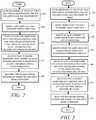
- FIG. 3is a flow chart showing another example method of operation of the apparatus of FIG. 1 in accordance with various embodiments.
- the method of operationbegins and in operation block 301, beamforming is used to create at least two virtual microphones, one for user voice and the other for noise.
- the beam formsare adjusted to locate dominant energy source directions.
- voice activity detectorsare used to identify if voice is present in either signal.
- voice recognition confidence metricsare used to identify whether any voice detected is the user's voice or is a jammer voice such that the signal may considered to be noise.
- At least one beamformis adjusted until voice is identified in at least one voice virtual microphone signal based on the voice recognition confidence metrics.
- at least a second beamformis adjusted until a jammer voice or background noise is identified in at least one noise virtual microphone signal.
- the first and second virtual microphone signalsare sent to a dual input noise suppressor, and the method of operation ends as shown.
- FIG. 4a flowchart shows an example method of operation related to formation of a virtual microphone and related beamform to obtain a voice signal in accordance with various embodiments.
- the apparatus 100may determine the orientation of the electronic device or system that incorporates the apparatus 100. For some systems that are relatively stationary, these operations may be omitted since the physical position of the device may be relatively constant. For example, a digital video recorder or television set located in a certain position within a room may remain relatively constant.
- the method of operationbegins as shown in decision block 401, where device orientation detector 105 may communicate with orientation sensors 107 and obtain the orientation of the device.
- the orientation informationmay be sent as orientation information 102 to the beamformer controller 190.
- the device orientation detector 105may send control signal 108 to microphone configuration logic 120 and adjust the microphone configuration accordingly.
- the beamformer controller 190will take on this role and will send control signal 194 to microphone configuration logic 120 and change the microphone configuration according to the received orientation information 102.
- the method of operationproceeds to operation block 405.
- operation block 405some or all of the microphones, of the group of microphones 110, are combined through the beamformer 130.
- the method of operationproceeds to decision block 407.
- the decision of whether noise suppression is required, in decision block 407,is based on the results of the evaluation of noise estimator 161 which evaluates the noise level on the voice signal 135 or the noise level in the user's environment of the signal-to-noise ratio of the user's speech in the user's acoustic environment.
- the control signal 145will be sent to the beamformer controller 190 to indicate that the current beamform is adequate.
- the voice signalmay therefore be used for various applications as-is without further noise suppression and the method of operation ends.
- the resulting noise and voice virtual microphone signalsare sent to the noise suppressor 170 in operation block 409.
- noise estimator 161sends voice and control signal 149 to the noise suppressor 170.
- the noise suppressor 170may obtain the buffered voice signal 118 from buffer 133 and may obtain the buffered noise signal 117 from buffer 134.
- the noise suppressor 170may access the system memory 103 over read-write connection 173, and obtain a pertinent noise suppressor algorithm from the noise suppressor algorithms database 171.
- the beamformer controller 190may send the control signal 155 to noise suppressor 170 to indicate a noise suppressor algorithm from the database of noise suppressor algorithms 171 that the noise suppressor 170 should execute.
- the noise estimator 161may check the noise suppressor 170 voice signal 157 to determine if the applied noise suppression algorithm was adequate. If the noise suppression was adequate, and if noise suppression is therefore no longer required in decision block 411, the method of operation ends. However, if noise suppression is still required in decision block 411, then the voice signal 157 may be sent to the voice recognition engine 180. In response, the voice recognition engine will send voice confidence metrics 159 to the beamformer controller 190. If the confidence scores are too low, then the beamformer controller 190 may determine that noise suppression is still required in decision block 415. If the confidence scores are sufficiently high in decision block 415, the noise suppression is no longer required and the method of operation ends. If noise suppression is still required in decision block 415, then the control signal 163 may invoke SI-VR 182 to determine if the user's voice is present in the signal. The method of operation then ends.
- the method of operation illustrated in FIG. 4may be truncated by omitting operation block 413 and decision block 415 and proceeding from decision block 411 directly to operation block 417.
- only the trained speech recognition logic SI-VR 182is utilized in an attempt to identify the presence of the user's voice in the voice signal.
- the trained speech recognition logic SI-VR 182may also be applied to the noise signal to verify that any voice present in the noise signal is mostly jammer voices and not the user's voice.
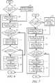
- FIG. 5is a flow chart showing another example method of operation related to formation of a virtual microphone and related beamform to obtain a voice signal in accordance with various embodiments.
- Decision block 501, operation block 503 and operation block 505involve operations similar to operation blocks 401, 403 and 405 of FIG. 4 and therefore need not be discussed here in detail. Therefore the method of operation proceeds to operation block 507, in which the noise and voice virtual microphone signals are immediately sent to noise suppressor 170.
- the resulting noise suppressed voice signal 157is sent to the SI-VR 182 logic in operation block 509.
- the beamformer controller 190accordingly receives the voice confidence metrics 159 and determines if further noise suppression is required as shown in decision block 511.
- the method of operationends and the voice beamform can be considered adequate. However, if the voice confidence metrics 159 are too low, then this indicates that further noise suppression would be required. The method of operation therefore proceeds to operation block 513.
- the beamformer controllersends control signal 194 to the microphone configuration logic 120 and selects a different set of physical microphones from the group of microphones 110 if appropriate. That is, all microphones may already be in use after operation block 503 or operation block 505.
- the beamformer controller 190sends control signal 195 to the beamformer 132 and pans or adapts the beamform or may select a predetermined beamform pattern from system memory 103 in the stored predetermined beamform patterns database 191. This is done in an attempt to steer the peak in sensitivity of the beam toward another location where voice may be detected. Therefore after operation block 515, the method of operation loops back to operation block 507 and the method of operation repeats as shown until success.
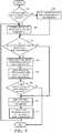
- FIG. 6is a flow chart showing an example method of operation related to formation of a virtual microphone and related beamform to obtain a noise signal with a jamming voice in accordance with various embodiments.
- Operation blocks 601, 603 and 605are again related to determining a mobile device orientation and have previously been discussed with respect to FIG. 4 and therefore need not be discussed in detail here.
- the method of operationproceeds to operation block 607, in which some or all of the virtual microphone signals are sent to speech recognition directly. Therefore beamformer controller 190 may send control signal 163 to the voice recognition engine 180 to instruct the voice recognition engine 180 to read the buffered noise signal 117.
- decision block 609the beamformer controller 190 checks the voice confidence metrics 159 to determine if voice appears to be present in any of the signals.
- the beamformer controller 190may check control signal 125 from VAD 152 to determine if voice activity detection has determined that voice may be present. If voice appears to be present in decision block 609, then the method of operation proceeds to operation block 611 and sends the signal to SI-VR 182 logic. If the user's voice is not detected in decision block 613, based on sufficiently low voice confidence metrics 159, the method of operation ends as shown. However if the voice confidence metrics 159 are high such that the user's voice is likely present, then the method of operation proceeds to operation block 615 in which a different set of physical microphones may be selected if appropriate as was described above, that is, assuming that additional microphones are available (i.e. in situations where only some of the available microphones were initially employed). In operation block 617, the beamformer controller 190 again controls the beamformer 132 to pan or adapt the beamform or selects a predetermined beamformer pattern in order to continue the search for a jammer voice.
- FIG. 7is a flow chart showing another example method of operation related to formation of a virtual microphone and related beamform to obtain a noise signal in accordance with various embodiments.
- Decision block 701 and operation block 703 and 705are again similar to other flowcharts in that they are related to determining the orientation of a mobile device and therefore will not be discussed in detail here.
- the method of operationproceeds to operation block 707 where some or all virtual microphone signals are sent directly to speech recognition, that is, to voice recognition engine 180.
- operation block 709some or all of the virtual microphone signals are also sent to the SI-VR logic 182.
- decision block 711voice activity detectors are checked along with the voice confidence metrics 159 to determine if any of the signals contain voice.
- the beamformer controller 190controls the beamformer 131 and pans or adapts the beamformer, or selects a predetermined beamform pattern from the database of beamformer patterns database 191 stored system memory 103. The method of operation then loops back to operation block 705 and continues until a successful noise beam has been determined.
- FIG. 8is a flow chart showing another example method of operation related to formation of a virtual microphone and related beamform to obtain a noise signal in accordance with various embodiments.
- Decision block 801 and operation block 803 and operation block 805are again related to determination of the orientation of a mobile device and will not be discussed herein in detail.
- the method of operationproceeds to decision block 807 in which the energy estimators are checked to determine whether the virtual microphone signal is in the direction of a dominant energy. If not, the method of operation then proceeds to operation block 815 and may select a different set of physical microphones of the group of microphones 110 if appropriate, that is, assuming that additional microphones are available (i.e. in situations where only some of the available microphones were initially or previously employed)..
- beamformer controller 190controls the beamformer 132 to pan or adapt the beamform or selects a predetermined beamform pattern as discussed above, and the method of operation loops back to operation block 805 and continues to search for the noise beam. If the energy estimator determines that the dominant energy source is found in decision block 807, then the method of operation proceeds to operation block 809 where some or all of the virtual microphone signals are sent to the voice recognition engine 180. In operation block 811, some or all of the virtual microphone signals are also sent to the SI-VR logic 182.
- decision block 813if voice is indicated by either the voice activity detector VAD 152, or the voice confidence metrics 159, then the method of operation again proceeds to operation block 815 where a different set of physical microphones may be selected in some situations as discussed above, etc., and in block 817 the beamformer may pan or adapt in the continued search for an environmental noise source. Whenever voice is not indicated in decision block 813, then the beamform can be considered to have successfully captured the environmental noise and the method of operation ends as shown.
- the noise estimator 162can send control signal 153 to the noise suppressor 170 when the voice signal and noise signal are to both be sent to the noise suppressor 170.
- the noise estimator 162receives control signal 143 from VAD 152.
- FIG. 1various combinations of the components shown in FIG. 1 such as the energy estimators, VADs, noise estimators, voice recognition or speaker identification voice recognition may be used to obtain the features and advantages provided by the present disclosure and that such various combinations are contemplated by the disclosure herein. Also it is to be understood that, in some embodiments, some of the aforementioned components may not be used or may not be present in any particular embodiment. In one example, if VAD is used to detect voice in the voice channel or the noise channel, the voice recognition engine 180 may not be used or may not be present in that embodiment.
- the VAD 151 or VAD 152may not be used or may not be present in that embodiment.
- the energy estimator 141 and energy estimator 142may not be used or may not be present in either example embodiment. Therefore, based on the description of the embodiments and various examples provide above herein, one of ordinary skill will understand that FIG. 1 contemplates all such various embodiments in view of the present disclosure. Other such contemplated embodiment examples therefore will become apparent to one of ordinary skill in light of the examples and disclosure provided herein.
- logicsuch as the microphone configuration logic 120, beamformers 130, buffers 133 and 134, energy estimators 141 and 142, VAD 151 and 152, noise estimators 161 and 162, noise suppressor 170, voice recognition engine 180, beamformer controller 190, or system control 101
- logicsuch as the microphone configuration logic 120, beamformers 130, buffers 133 and 134, energy estimators 141 and 142, VAD 151 and 152, noise estimators 161 and 162, noise suppressor 170, voice recognition engine 180, beamformer controller 190, or system control 101
- programmable processorssuch as a central processing unit (CPU) or the like, or by ASICs, DSPs, FPGAs, hardwired circuitry (logic circuitry), or any combinations thereof.
- control signalsmay be implemented in various ways such as using application programming interfaces (APIs) between the various components. Therefore, in some embodiments, components may be operatively coupled using APIs rather than a hardware communication bus if such components are implemented as by software and/or firmware executing on one or more programmable processors.
- the beamformer controller 190 and the noise suppressor 170may be software and/or firmware executing on a single processor and may communicate and interact with each other using APIs.
- the beamformers 130 and the beamformer controller 190may be software and/or firmware executing on a single processor and may communicate and interact with each other using APIs. Additional similar examples will be apparent to those of ordinary skill in light of the examples and description provide herein.
- operations involving the system memory 103may be implemented using pointers where the components such as, but not limited to, the beamformer controller 190 or the noise suppressor 170, access the system memory 103 as directed by control signals which may include pointers to memory locations or database access commands that access the pre-determined beamform patterns database 191 or the database of noise suppression algorithms 171 or etc., respectively.
- the beamforming methods of operations disclosed hereinmay be used to determine a voice and noise signal for the purpose of identifying a user for a voice uplink channel of a mobile telephone and/or for applying dual or multi-input noise suppression for a voice uplink channel of a mobile telephone.
- a stationary conference call systemmay incorporate the apparatuses and methods herein described.
- Other applications of the various disclosed embodimentswill be apparent to those of ordinary skill in light of the description and various example embodiments herein described.
Landscapes
- Engineering & Computer Science (AREA)
- Physics & Mathematics (AREA)
- Health & Medical Sciences (AREA)
- Acoustics & Sound (AREA)
- Signal Processing (AREA)
- Human Computer Interaction (AREA)
- Audiology, Speech & Language Pathology (AREA)
- Multimedia (AREA)
- Computational Linguistics (AREA)
- Quality & Reliability (AREA)
- General Health & Medical Sciences (AREA)
- Otolaryngology (AREA)
- Soundproofing, Sound Blocking, And Sound Damping (AREA)
- Circuit For Audible Band Transducer (AREA)
Description
- The present disclosure relates generally to voice processing and more particularly to beamforming systems and methods of applying dual or multi-input noise suppression.
- Mobile devices such as, but not limited to, mobile phones, smart phones, personal digital assistants (PDAs), tablets, laptops or other electronic devices, etc., increasingly include voice recognition systems to provide hands free voice control of the devices. Although voice recognition technologies have been improving, accurate voice recognition remains a technical challenge when the voice of interest is in the presence of other talkers or ambient noise. These technical challenges exist not only for voice recognition technologies, but also for voice processing such as that used in telephony which today may be performed using almost any electronic device having a suitable telephony application, notwithstanding the prevalence of mobile phones and smart phones.
- A particular challenge when implementing voice transmission or voice recognition systems on mobile devices is that many types of mobile devices support use cases where the user (and therefore the user's voice) may be at different positions relative to the mobile device depending on the use case. Adding to the challenge is that various noise sources including other talkers (i.e. jammer voices) may also be located at different positions relative to the mobile device. Some of these noise sources may vary as a function of time in terms of location and magnitude. All of these factors make up the acoustic environment in which a mobile device operates and impacts the sound picked up by the mobile device microphones. Also, as the mobile device is moved or is positioned in certain ways, the acoustic environment of the mobile device also changes accordingly thereby also changing the sound picked up by the mobile device's microphones. Voice sound that may be recognized by the voice recognition system or by a listener on the receiving side of a voice transmission system under one acoustic environment may be unrecognizable under certain changed conditions due to mobile device motion, positioning, or ambient noise levels. Various other conditions in the surrounding environment can add noise, echo or cause other acoustically undesirable conditions that also adversely impact the voice recognition system or voice transmission system.
- More specifically, the mobile device acoustic environment impacts the operation of signal processing components such as microphone arrays, noise suppressors, echo cancellation systems and signal conditioning that is used to improve both voice recognition and voice call performance. For mobile devices and also for stationary devices, the speaker and other jammer speakers or other noise sources may also change locations with respect to the device microphones. This also results in undesirable impacts on the acoustic environment and may result in voice being unrecognizable by the voice recognition system or a listener due to noise interference caused by the jammer speakers or other noise sources.
- US patent application publication no.
US2010/217590 describes a system and method for performing speaker localization. The system and method utilizes speaker recognition to provide an estimate of the direction of arrival (DOA) of speech sound waves emanating from a desired speaker with respect to a microphone array included in the system. Candidate DOA estimates may be preselected or generated by one or more other DOA estimation techniques. The system and method is suited to support steerable beamforming as well as other applications that utilize or benefit from DOA estimation. - US patent application publication no.
US2013/030803 describes a microphone-array-based speech recognition system which combines a noise cancelling technique for cancelling noise of input speech signals from an array of microphones, according to at least an inputted threshold. The system receives noise-cancelled speech signals outputted by a noise masking module through at least a speech model and at least a filler model, then computes a confidence measure score with the at least a speech model and the at least a filler model for each threshold and each noise-cancelled speech signal, and adjusts the threshold to continue the noise cancelling for achieving a maximum confidence measure score, thereby outputting a speech recognition result related to the maximum confidence measure score. PCT patent application publication no. WO 94/16517 - In accordance with aspects of the invention, there are provided methods and apparatus, as recited in the accompanying claims.
FIG. 1 is a schematic block diagram of an apparatus in accordance with the embodiments.FIG. 2 is a flow chart providing an example method of operation of the apparatus ofFIG. 1 in accordance with various embodiments.FIG. 3 is a flow chart showing another example method of operation of the apparatus ofFIG. 1 in accordance with various embodiments.FIG. 4 is a flow chart showing an example method of operation related to formation of a virtual microphone to obtain a voice signal in accordance with various embodiments.FIG. 5 is a flow chart showing another example method of operation related to formation of a virtual microphone to obtain a voice signal in accordance with various embodiments.FIG. 6 is a flow chart showing an example method of operation related to formation of a virtual microphone to obtain a noise signal with a jamming voice in accordance with various embodiments.FIG. 7 is a flow chart showing another example method of operation related to formation of a virtual microphone to obtain a noise signal in accordance with various embodiments.FIG. 8 is a flow chart showing another example method of operation related to formation of a virtual microphone to obtain a noise signal in accordance with various embodiments.- Briefly, a method of operation of the disclosed embodiments includes beamforming a plurality of microphone outputs to obtain a plurality of virtual microphone audio channels. Each virtual microphone audio channel corresponds to a beamform. The virtual microphone audio channels include at least one voice channel and at least one noise channel. The method includes performing voice activity detection on the at least one voice channel and adjusting a corresponding voice beamform until voice activity detection indicates that voice is present on the at least one voice channel.
- The method further includes performing voice activity detection on the at least one noise channel and adjusting a corresponding noise beamform until voice activity detection indicates that voice is not present on the at least one noise channel. The method may further include performing energy estimation on the at least one noise channel and adjusting a corresponding noise beamform until energy estimation indicates that the at least one noise channel is receiving audio from a dominant audio energy source. The method may further include performing voice recognition on the at least one voice channel and adjusting the corresponding voice beamform to improve a voice recognition confidence metric of the voice recognition. The method may further include performing voice recognition on the at least one noise channel and adjusting the corresponding noise beamform to decrease a voice recognition confidence metric of the voice recognition performed on the noise beam.
- In some embodiments, performing voice recognition on the at least one noise channel may include performing voice recognition on the at least one noise channel using trained voice recognition that is trained to identify a specific speaker. The method may further include configuring the plurality of microphone outputs initially based on a detected orientation of a corresponding group of microphones.
- Another method of operation being an example not in accordance with the claimed invention includes beamforming a plurality of microphone outputs to obtain a plurality of virtual microphone audio channels, where each virtual microphone audio channel corresponds to a beamform, and with at least one voice channel and at least one noise channel. The method includes performing voice recognition on the at least one voice channel and adjusting the corresponding voice beamform to improve a voice recognition confidence metric of the voice recognition.
- In some examples not in accordance with the claimed invention, performing voice recognition on the at least one voice channel may include performing voice recognition on the at least one voice channel using trained voice recognition that is trained to identify a specific speaker. The method may further include performing voice activity detection on the at least one noise channel and adjusting a corresponding noise beamform until voice activity detection indicates that voice is not substantially present on the at least one noise channel. The method may further include performing energy estimation on the at least one noise channel and adjusting the corresponding noise beamform until energy estimation indicates that the at least one noise channel is receiving audio from a dominant audio energy source. The method may further include performing voice activity detection on the at least one noise channel and adjusting a corresponding noise beamform until voice activity detection indicates that voice is present on the at least one noise channel. The method may further include performing voice recognition on the at least one noise channel and adjusting the corresponding noise beamform to decrease a voice recognition confidence metric of the voice recognition. The method may further include performing voice recognition on the at least one noise channel using trained voice recognition that is trained to identify a specific speaker. The method may further include performing voice recognition on the at least one noise channel in response to voice activity detection indicating that voice is present on the at least one noise channel. The method may further include adjusting the corresponding noise beamform to decrease a voice recognition confidence metric of the trained voice recognition.
- The disclosed embodiments also provide an apparatus that includes a beamformer, operatively coupled to a plurality of microphone outputs. The beamformer is operative to provide, as beamformer outputs, a plurality of virtual microphone audio channels where each virtual microphone audio channel corresponds to a beamform and with at least one voice channel and at least one noise channel. A beamformer controller is operatively coupled to the beamformer and is operative to monitor the at least one voice channel and the at least one noise channel to determine if voice is present on either of the at least one voice channel or the at least one noise channel. The beamformer controller is also operative to control the beamformer to adjust a beamform corresponding to the at least one voice channel until voice is present on the at least one voice channel. In some embodiments, the beamformer controller is also operative to control the beamformer to adjust a beamform corresponding to the at least one noise channel until voice is not present on the at least one noise channel.
- In one embodiment, a voice activity detector is operatively coupled to the beamformer to receive the at least one voice channel, and to the beamformer controller. The beamformer controller of this embodiment is operative to monitor the at least one voice channel to determine if voice is present by monitoring input received from the voice activity detector. In another embodiment, a voice recognition engine is operatively coupled to the beamformer to receive the at least one voice channel, and to the beamformer controller. The voice recognition engine is operative to perform voice recognition on the at least one voice channel to detect voice, and the beamformer controller is operative to monitor the at least one voice channel to determine if voice is present by monitoring input received from the voice recognition engine. The input may be, for example, voice confidence metrics.
- In another example not in accordance with the claimed invention, a voice recognition engine is operatively coupled to the beamformer to receive the at least one voice channel and at least one noise channel. The voice recognition engine is operative to perform voice recognition on the at least one voice channel and at least one noise channel to detect voice. A beamformer controller is operatively coupled to the beamformer, to a voice activity detector and to the voice recognition engine. The beamformer controller is operative to, among other things, monitor the voice activity detector to determine if voice is present on either of the at least one voice channel or the at least one noise channel and control the beamformer to adjust a corresponding voice beamform until voice activity detection or the voice recognition engine indicates that voice is present on the at least one voice channel and adjust a corresponding noise beamform until voice activity detection or the voice recognition engine indicates that voice is not substantially present on the at least one noise channel.
- In some examples not in accordance with the claimed invention, the apparatus may also include an energy estimator, operatively coupled to the beamformer and to the voice activity detector. In some embodiments, the apparatus may further include microphone configuration logic, operatively coupled to the beamformer. The microphone configuration logic may include switch logic that is operative to switch any microphone output of the plurality of microphone outputs on or off. In some embodiments, the apparatus may also include a noise estimator, operatively coupled to the voice activity detector.
- In another embodiment, a method of operation includes beamforming a plurality of microphone outputs to obtain at least one virtual microphone channel, performing voice recognition on the at least one virtual microphone channel, and adjusting a corresponding beamform until voice recognition indicates that voice is not present on the at least one virtual microphone channel. In some embodiments, performing voice recognition may include performing voice recognition on the at least one virtual microphone channel using trained voice recognition that is trained to identify a specific speaker.
- Turning now to the drawings,
FIG. 1 is a schematic block diagram of anapparatus 100 in accordance with various embodiments. Theapparatus 100 may be incorporated into and used in any electronic device that employs voice-recognition, voice transmission, or voice capture. One application of theapparatus 100 may be used in any of various mobile devices such as, but not limited to, a mobile telephone, smart phone, camera, video camera, tablet, laptop, or some other battery-powered electronic device, etc., however theapparatus 100 is not limited to use in mobile devices. For example, theapparatus 100 may be used in voice controlled television sets, digital video recorders, automobile control systems, or any other device or system that employs voice recognition or voice communication, such as portable or non-portable telephones, speakerphones, etc. - It is to be understood that
FIG. 1 is limited, for the purpose of clarity, to showing only those components useful to describe the features and advantages of the various embodiments, and to describe how to make and use the various embodiments to those of ordinary skill. It is therefore to be understood that various other components, circuitry, and devices etc. may be present in order to implement an apparatus and that those various other components, circuitry, devices, etc., are understood to be present by those of ordinary skill. For example, the apparatus may include inputs for receiving power from a power source, a power distribution bus that may be connected to a battery or other power source housed within one of the electronic devices or systems in which theapparatus 100 is incorporated, to provide power to theapparatus 100 or to distribute power to the various components of theapparatus 100. In another example, the apparatus may include one or more communication buses for sending control signals or other information between operatively coupled components, etc. Thus it is to be understood that such various other components, circuitry, or devices are omitted for the purpose of clarity. - Another example is that the
apparatus 100 may also include an internal communication bus, for providing operative coupling between the various components, circuitry, and devices. The terminology "operatively coupled" as used herein refers to coupling that enables operational and/or functional communication and relationships between the various components, circuitry, devices etc. described as being operatively coupled and may include any intervening items (i.e. buses, connectors, other components, circuitry, devices etc.) used to enable such communication such as, for example, internal communication buses such as data communication buses or any other intervening items that one of ordinary skill would understand to be present. Also, it is to be understood that other intervening items may be present between "operatively coupled" items even though such other intervening items are not necessary to the functional communication facilitated by the operative coupling. For example, a data communication bus may be present in various embodiments of theapparatus 100 and may provide data to several items along a pathway along which two or more items are operatively coupled, etc. Such operative coupling is shown generally inFIG. 1 described herein. - In
FIG. 1 theapparatus 100 may include a group ofmicrophones 110 that provide microphone outputs and that are operatively coupled tomicrophone configuration logic 120. Although the example ofFIG. 1 shows four microphones, with each oriented in a different direction, the embodiments are not limited to four microphones or the example orientations shown and any number of microphones and microphone orientations may be used in the embodiments. It is to be understood that the group ofmicrophones 110 are shown using a dotted line inFIG. 1 because the group ofmicrophones 110 is not necessarily a part of theapparatus 100. In other words, the group ofmicrophones 110 may be part of a mobile device or other electronic device or system into which theapparatus 100 is incorporated. In that case, theapparatus 100 is operatively coupled to the group ofmicrophones 110, which are located within the mobile device, by a suitable communication bus or suitable connectors, etc., such that the group ofmicrophones 110 are operatively coupled to themicrophone configuration logic 120. - The
microphone configuration logic 120 may include various front end processing, such as, but not limited to, signal amplification, analog-to-digital conversion/digital audio sampling, echo cancellation, etc., which may be applied to the group ofmicrophone 110 outputs prior to performing additional, less power efficient signal processing such as noise suppression. In some embodiments, themicrophone configuration logic 120 may also include switch logic operatively coupled to the group ofmicrophones 110 and operative to respond to control signals to individually turn each of the microphones on or off to configure the microphones in various ways. Alternatively, in some embodiments, the microphones may be turned on or off by adjusting a gain or amplifier associated with a corresponding microphone output. For example, a microphone may be turned off by reducing a gain value to zero for the corresponding microphone output. Additionally, in some embodiments, themicrophone configuration logic 120 may be operative to receive control signals from other components of theapparatus 100 to adjust front end processing parameters such as, for example, amplifier gain. - The
microphone configuration logic 120 is operatively coupled tobeamformer 130. In some embodiments, thebeamformer 130 may be implemented as a single beamformer with multiple outputs. Each output of thebeamformer 130 represents a virtual microphone signal where the virtual microphone is created by beamforming the outputs from one or more physical microphones of the group ofmicrophones 110. In the example embodiment illustrated byFIG. 1 , thebeamformer 130 is implemented as two or more separate beamformers,beamformer 131 andbeamformer 132 in order to increase the speed of operation. Eachbeamformer microphones 110 based on themicrophone configuration logic 120 or by selecting microphone outputs as needed for given beamform patterns bybeamformer controller 190 or by the beamformers independently. That is, in some embodiments, switch logic ofmicrophone configuration logic 120 may switch some or all microphone outputs tobeamformer 131 and some or all tobeamformer 132 in various combinations and configurations, or in other embodiments thebeamformer controller 190, or the beamformers independently, may control which microphones are used as needed for given beamform patterns and may turn microphones on or off by adjusting gain applied within the beamformers. For example, in a mobile device application of theapparatus 100, microphones may be configured by either switch logic, by thebeamformer controller 190 or by the beamformers, based on the orientation of the mobile device. - In some embodiments, a
device orientation detector 105 is operatively coupled to themicrophone configuration logic 120 and to one ormore orientation sensors 107. One example of an orientation sensor is a gyroscope, from which thedevice orientation detector 105 may receive sensor data overconnection 106 and determine the positioning of the mobile device. For a given orientation, thedevice orientation detector 105 may send control signal 108 to themicrophone configuration logic 120 to turn off or turn on certain microphones of the group ofmicrophones 110. In other words, various mobile device use cases or mobile device orientations may be associated with certain microphone configurations and such microphone configurations may be triggered by actions taken on the device in conjunction with device orientations. This may be based on pre-determined configuration settings for given orientations in some embodiments, or may be based on other or additional criteria in other embodiments. For example, placing a device in a docking station may trigger engaging a pre-determined microphone configuration. In another example, placing the device in a speakerphone mode and placing the device on a tabletop or desktop may trigger another pre-determined microphone configuration. Thus in some embodiments, thedevice orientation detector 105, when present, may sendorientation information 102 to thebeamformer controller 190 such that thebeamformer controller 190 may control or override such use case or orientation related settings of themicrophone configuration logic 120. - The
example apparatus 100 embodiment ofFIG. 1 includes two voice detection paths, one for each virtual microphone output of eachbeamformer FIG. 1 shows two virtual microphone outputs,voice signal 135 andnoise signal 136, any number of virtual voice or noise signals may be generated in the various embodiments. In the present example, each of the two virtual microphone outputs is, when needed, provided to a dualinput noise suppressor 170. In other embodiments that utilize multiple voice and/or noise signals, a multiple input noise suppresser may be used. In another embodiment, multiple two-input noise suppressors may be used in series to produce a single de-noised output signal. In yet other embodiments, multiple two-input noise suppressors or multiple multi-input noise suppressors may be used in parallel and each output may be sent to thevoice recognition engine 180. In such embodiments, whichever output produces the best trained or untrained voice confidence metric may be utilized. - Two symmetrical paths exist between the respective beamformers 131 and 132 and the
noise suppressor 170; one for virtualmicrophone voice signal 135 and one for virtualmicrophone noise signal 136. The two paths are symmetrical in that they each employ arespective energy estimator beamformers energy estimators noise estimator VAD noise estimators noise suppressor 170 to providerespective control signals noise estimator 162 receive control signal 143 fromVAD 152. The two pathways, including all the components described above, may be considered as a "voice channel" and "noise channel." That is, a voice signal and a noise signal are sent along the respective pathways through the various components along with control signals between components when appropriate. The voice signal or noise signal may be passed along the pathways and through some of the components without any processing or other action being taken by that component in some embodiments. The voice channel and noise channel are virtual channels that are related to a corresponding voice beamform and noise beamform. The voice beamform may be created bybeamformer 131 and the noise beamform may be created bybeamformer 132. Thevoice signal 135 may be considered a voice channel which may also be considered to be one of the virtual microphone outputs. Thenoise signal 136 may be considered to be noise channel which may also be considered to be another one of the virtual microphone outputs. The "virtual microphones" correspond to beamforms that may incorporate audio from one or more physical microphones of the group ofmicrophones 110. AlthoughFIG. 1 provides an example of one "voice channel" and one "noise channel," any number of voice channels or noise channels may be created and used in the various embodiments. Also, the various channel components, in some embodiments, may be single integrated components that perform operations for one or more channels. For example,energy estimator 141 andenergy estimator 142 may be integrated as a single energy estimator that serves both the voice channel and the noise channel by providing dual inputs or in a time domain multiple access approach or some other suitable approach. TheVAD 151 andVAD 152 or thenoise estimator 161 andnoise estimator 162 may also be implemented in an integrated manner in some embodiments. - Each virtual microphone output is operatively coupled to a
respective buffer beamformers 130 may be buffered and sent to thevoice recognition engine 180 while thebeamformers 130 continue to adjust beamform patterns to improve the voice and noise signals. - For purposes of explanation, the
voice signal 135 pathway will be described first in detail. The symmetrical pathway for thenoise signal 136 operates in a similar manner, and any differences will be addressed below. Therefore, beginning withvoice signal 135, theenergy estimator 141 is operatively coupled to thebuffer 133 and toVAD 151. Theenergy estimator 141 provides acontrol signal 109 to thebuffer 133, a voice and control signal 119 to theVAD 151 and acontrol signal 111 to thebeamformer controller 190. Thenoise signal 136energy estimator 142 provides acontrol signal 113 to buffer 134. In some embodiments, thebuffer 133 and buffer 134 may each be controlled byVAD 151 andVAD 152, respectively, andenergy estimator 141 andenergy estimator 142 may not be present. That is, in some embodiments,VAD 151 andVAD 152 are used to detect voice energy in respective beamform patterns generated bybeamformers 130 rather than initially looking for unspecific audio energy as when using the energy estimators. In other embodiments, the VAD may be omitted and, instead, thevoice recognition engine 180 and voice confidence metrics alone (without the VAD) may be used as an indicator of the presence of voice in signal. These operations are discussed further herein below with respect to various embodiments and various related methods of operation. - The
VAD 151 is further operatively coupled to anoise estimator 161 and provides a voice andcontrol signal 127. TheVAD 151 is operatively coupled to thebeamformer controller 190 and provides control signal 123 which informs thebeamformer controller 190 when theVAD 151 has detected voice. Thenoise estimator 161 may be a signal-to-noise ratio (SNR) estimator in some embodiments, or may be some other type of noise estimator. Thenoise estimator 161 is operatively coupled to thebeamformer controller 190 and provides control signal 145 which informs thebeamformer controller 190 when noise suppression is required for thevoice signal 135. In other words,control signal 145 provides information to thebeamformer controller 190 which in turn controls thebeamformer 131 so that thebeamformer 131 may continue to scan or may adjust the beamform pattern in order to reduce some of the noise contained in the voice signal. - Each of the
components VAD noise estimator respective buffer 133 andbuffer 134, to receive bufferedvoice signal 118 or bufferednoise signal 117, respectively.Noise suppressor 170 may be operatively coupled to bothbuffer 133 and buffer 134 to receive both the bufferedvoice signal 118 and the bufferednoise signal 117. These connections are not shown inFIG. 1 for clarity in showing the various other control connections, etc. - Therefore,
noise estimator 161 may receive the buffered voice signal 118 from thebuffer 133 and providescontrol signal 145 to thebeamformer controller 190, and voice and control signal 149 tonoise suppressor 170.Noise estimator 161 is also operatively coupled tonoise estimator 162 by control anddata connection 160 such that the two noise estimators can obtain and use information from the other channel to perform various noise estimation operations in some embodiments. Thenoise suppressor 170 is operatively coupled to thevoice recognition engine 180 to provide a noise suppressedvoice signal 157, to thebeamformer controller 190 to receivecontrol signal 155, and tosystem memory 103 by read-write connection 173. Thenoise suppressor 170 may accesssystem memory 103 to read and retrieve noise suppression algorithms, stored in noisesuppression algorithms database 171, for execution by thenoise suppressor 170. Thebeamformer controller 190 is operatively coupled tosystem memory 103 by a read-write connection 193 to access pre-determined beamform patterns stored in abeamform patterns database 191. Thesystem memory 103 is a non-volatile, non-transitory memory. - The
noise suppressor 170 may receive the buffered voice signal 118 from thebuffer 133 and provide a noise suppressedvoice signal 157 to thevoice recognition engine 180 and/or to one ormore voice transceivers 104 in some embodiments. In some embodiments, thevoice recognition engine 180 may not be used and may not be present. That is, in some embodiments, the noise suppressedvoice signal 157 may only be provided to one ormore voice transceivers 104 for transmission on either by a wired or wireless telecommunications channel or over a wired or wireless network connection if a voice over Internet protocol (VoIP) system is employed by the device into which theapparatus 100 is incorporated. In embodiments having thevoice recognition engine 180 present, thevoice recognition engine 180 may be operatively coupled to thesystem control 101, which may be any type of voice controllable system control depending on the device in which theapparatus 100 is incorporated such as, but not limited to, a voice controlled dialer of a mobile telephone, a video recorder system control, an application control of a mobile telephone, smartphone, tablet, laptop, in-vehicle control system, etc., or any other type of voice controllable system control. However, thesystem control 101 may not be present in all embodiments. The voice recognition engine includes basic voice recognition (VR)logic 181 that recognizes human speech. In some embodiments, thevoice recognition engine 180 may additionally, or alternatively, include speaker identification voice recognition logic (SI-VR) 182 which is trained to recognize specific human speech, such as the speech of a specific user. - A
control signal 163, sent by thebeamformer controller 190, may invoke either theVR logic 181 or the SI-VR logic 182. In response to thecontrol signal 163 instructions, either theVR logic 181 or the SI-VR logic 182 will read either, or both of, the bufferednoise signal 117 or bufferedvoice signal 118. Thevoice recognition engine 180 will provide a voice-to-text stream with corresponding voice confidence metrics on each phrase or group of words as an indication (i.e. a confidence score) to thebeamformer controller 190 of the likelihood of recognized human speech, or the likelihood of a specific user's speech if the SI-VR logic 182 has been invoked. This indication is shown inFIG. 1 asvoice confidence metrics 159. Thevoice recognition engine 180 may also send control signal 165 to thesystem control 101 in response to detected command words, command phrases or other speech (such as for speech-to-text applications) received on thevoice signal 157 or on the bufferedvoice signal 118 in some embodiments in which thevoice recognition engine 180 is also used as a control function for theapparatus 100. - In the various embodiments, the
beamformer controller 190 is operative to monitor various control signals which provide various indications of conditions on thevoice signal 135 andnoise signal 136. In response to the conditions, thebeamformer controller 190 is operative to make adjustments to thebeamformers 130 to change the beamform directivity. For example, thebeamformer controller 190 attempts to adjust thebeamformer 131 until thevoice signal 135 is substantially the user's voice. Additionally, thebeamformer controller 190 attempts to adjust thebeamformer 132 until thenoise signal 136 is tied to noises and sounds in the acoustic environment of the user other than the user's voice such as a jammer voice or voices or other environmental background noise. - In some embodiments, the formation of a single beamform may be sufficient in some situations. For example, by using a VAD,
VR logic 181 or the SI-VR logic 182 (i.e. trained VR) to form a voice beamform channel along with using a noise suppressor may provide sufficient fidelity and de-noising for a given application or for a given acoustic environment. Also, a noise beamform channel using trained VR to substantially eliminate the user's voice and using a noise suppressor may also provide sufficient fidelity and de-noising for a given application or for a given acoustic environment. - The
beamformer controller 190 is operative to configure the group ofmicrophones 110 which may be accomplished in some embodiments by controlling themicrophone configuration logic 120 to turn microphones on or off according to device orientation detected bydevice orientation detector 105, or other conditions. In some embodiments, thebeamformer controller 190 may generate random beamforms for the voice or noise signal paths where the appropriate signal path components check the results of each. In other example not in accordance with the claimed invention, thebeamformer controller 190 may cause the virtual microphone beamforms to change such that the beamforms pan or scan an audio environment until desired conditions are obtained. In yet other embodiments, thebeamformer controller 190 may configure thebeamformers 130 using pre-determined beamform patterns stored in abeamform patterns database 191 stored insystem memory 103. In yet other embodiments,beamformer 131 andbeamformer 132 may be adaptive beamformers that are operative to determine the magnitude and phase coefficients needed to combine microphone outputs of the group ofmicrophones 110 in order to steer a beam or a null in a desired direction. In the various embodiments, thebeamformer controller 190 is operative to, and may, monitor control signals from any of the following components, in any combination, such ascontrol signal 111 received fromenergy estimator 141, control signal 115 fromenergy estimator 142, control signal 123 fromVAD 151, control signal 125 fromVAD 152, control signal 145 fromnoise estimator 161 and/or control signal 147 fromnoise estimator 162. Thebeamformer controller 190 may also receivevoice confidence metrics 159 from thevoice recognition engine 180. The beamformer is operative to send acontrol signal 155 tonoise suppressor 170 to invoke noise suppression under certain conditions that are described herein. In some embodiments, thebeamformer controller 190 may be integrated intobeamformers 130 such thatbeamformers 130 include all the features of the beamformer controller. - The disclosed embodiments employ
VAD 151 andVAD 152 to distinguish voice activity from noise (and vice versa) and accordingly sendrespective control signals beamformer controller 190. The embodiments also utilizenoise estimator 161 andnoise estimator 162 to determine when to enable or disable noise reduction if voice cannot be properly distinguished from the signal. - The
beamformer 190 accordingly adjusts the beamform directivity ofbeamformer 131 andbeamformer 132 based on energy levels detected byenergy estimator 141 andenergy estimator 142, voice activity as determined byVAD 151 orVAD 152, and thenoise estimators beamformer 190 may adjust the respective beamform pattern. If voice is detected, the noise estimator looks to determine if noise suppression is required or if the signal is sufficient as is. If noise suppression is needed, thebeamformer 190 may send control signal 155 to activate thenoise suppressor 170 and to perform a voice confidence metric test on thevoice signal 157 by thevoice recognition engine 180. - Thus, the
energy estimators beamformers energy estimator 141 may send control signal 119 to activateVAD 151 to determine if voice is actually present in the received audio signal. Short-term deviations exceeding a threshold may also invoke sendingcontrol signal 109 to buffer 133 to invoke buffering the signal. - An example method of operation of the
apparatus 100 may be understood in view of the flowchart ofFIG. 2 . The method of operation begins inoperation block 201 in which theapparatus 100 uses beamforming to create at least two virtual microphones. One virtual microphone is for the user's voice and the other virtual microphone is for noise. For example as shown inFIG. 1 ,beamformer 131 outputs the virtualmicrophone voice signal 135 andbeamformer 132 outputs the virtualmicrophone noise signal 136. Inoperation block 203, thebeamformer controller 190 adjusts one or both of the beamforms to locate dominant energy directions. For example, in some embodiments, theenergy estimator 141 may detect an energy level above a threshold and accordingly send thecontrol signal 111 to thebeamformer 190 to inform thebeamformer controller 190 that a high energy level has been detected. However, in embodiments that do not require theenergy estimator 141, theVAD 151 is used to detect voice activity initially instead. Also in some embodiments, a timeout timer may be used such that, if no energy is detected by the energy estimator within a given time period, thebeamformer controller 190 may proceed to change the beamform in order to search for a dominant energy source by, for example, employing an adaptive beamformer to determine the magnitude and phase coefficients to steer a beam or a null toward a dominant energy source. In one example of operation, one beamform may be steered in the direction of the user's voice to form the virtual microphone voice channel, and a null may be steered in the direction of the user's voice to form the virtual microphone noise channel. - Acoustic textbook beam-patterns for differential dual-microphone arrays include bidirectional, hyper-cardioid, and cardioid shapes, whose polar patterns have infinite depth nulls. In typical physical systems, the phase and magnitude mismatches between microphone signals are influenced by various factors such as hardware, A/D converter precision, clocking limitations etc. The physical separation distance between microphones and their surrounding structure further reduces the depth of these nulls. In typically realized broad-band signal systems, the null depth of a cardioid pattern may be as little as 10 dB, or as high as 36 dB. Therefore, if a null is directed toward the only jammer talker or noise source present, the expected attenuation of that noise source or jammer could be as least 10 to 12 dB. Note that with perfectly matched microphones and signal processing channels, the attenuation can be much higher. If there are multiple jammer talkers or noise sources oriented in multiple directions, the maximum attenuation realizable with only one steerable null will be less than this 10 to 12 dB value. In one embodiment, in order to form a noise beam, the beamformer controller (190) can steer a null at a desired voice. The desired voice will be attenuated by the aforementioned amounts, and the noise beam will thus be substantially noise. In another embodiment, in order to form a voice beam, the beamformer controller (190) can steer a null at a jammer talker source. The resulting signal will then be substantially voice, having only a small component of jammer signal, as it was attenuated by the aforementioned amount. In yet another embodiment, in the case of a diffused sound field, the beamformer controller (190) can orient a hypercardioid beamform in the direction of a desired talker, thereby forming a signal that is substantially voice due to the -6dB random energy efficiency of the beam pattern relative to that of an omnidirectional microphone.
- In
operation block 205, thebeamformer controller 190 adjusts at least one beam form until voice is identified on at least one voice virtual microphone signal based on verification by voice activity detection and/or voice recognition confidence metrics. In one example,VAD 151 orVAD 152 will be invoked to determine whether voice is present in the signal or not. For example, ifVAD 151 does not detect voice in the signal, thenVAD 151 may send control signal 123 to thebeamformer controller 190 to indicate that thebeamformer controller 190 should readapt, or in some other way continue to search for voice by changing the beamform accordingly. - In
operation block 207, thebeamformer controller 190 adjusts at least a second beamform until either a jammer voice or background noise is identified in at least one noise virtual microphone signal. For example, in one embodiment,VAD 152 may be used to determine whether voice is present in thenoise signal 136 or not. In some embodiments, for situations where theVAD 152 detects that voice is present, theVAD 152 may send control signal 125 tobeamformer controller 190 to invoke usage of thevoice recognition engine 180 to further refine the voice detection. For example, thebeamformer controller 190 may send control signal 163 to thevoice recognition engine 180 to command the SI-VR 182 logic to analyze the bufferednoise signal 117 and determine if any voice detected is that of the user. If the user's voice is detected, based on thevoice confidence metrics 159 returned to thebeamformer controller 190, thebeamformer controller 190 may change the beamform to look for another dominant energy source (i.e. continue to search for noise). If the user's voice is not detected by the SI-VR 182 logic, then in some embodiments the voice activity detected byVAD 152 may be assumed to be jammer voices (i.e. a noise source). Also, if the voiceactivity detector VAD 152 does not detect voice, then thecontrol signal 125 may indicate to thebeamformer controller 190 that only background noise has been detected in thenoise signal 136 and that therefore, in either of the above example scenarios the search for a noise source (with either ambient noise, jammer voices, or both) was successful. - In
operation block 209, the first and second virtual microphone signals are sent to a dual input noise suppressor. Under certain conditions, the virtual microphone outputs will be sent to thenoise suppressor 170. In other words, in some instances, the beamforming of thevoice signal 135 may produce an adequately de-noised voice signal such that further noise suppression is not required. Thenoise estimators noise estimators voice recognition engine 180 to function properly, or if the user's voice will be sufficiently understood by far end listeners (because it has sufficiently little background noise). For example, if voice confidence metrics are too low for the voice signal, then thenoise suppressor 170 may need to be applied. In accordance with the embodiments, the beamformed virtual microphone voice signal and the beamformed virtual microphone noise signal are therefore used as inputs to a noise suppressor. That is, once thenoise signal 136 is determined to contain only background noise as was described above, or is found to contain a jammer's voice, then thenoise signal 136 may be considered adequate for use as an input to the noise suppressor and thebeamformer controller 190 will send control signal 155 tonoise suppressor 170 to proceed with the dual input noise suppression procedures. The method of operation then ends as shown. FIG. 3 is a flow chart showing another example method of operation of the apparatus ofFIG. 1 in accordance with various embodiments. The method of operation begins and inoperation block 301, beamforming is used to create at least two virtual microphones, one for user voice and the other for noise. Inoperation block 303, the beam forms are adjusted to locate dominant energy source directions. Inoperation block 305, voice activity detectors are used to identify if voice is present in either signal. Inoperation block 307, voice recognition confidence metrics are used to identify whether any voice detected is the user's voice or is a jammer voice such that the signal may considered to be noise.- In
operation block 309, at least one beamform is adjusted until voice is identified in at least one voice virtual microphone signal based on the voice recognition confidence metrics. Inoperation block 311, at least a second beamform is adjusted until a jammer voice or background noise is identified in at least one noise virtual microphone signal. In operation block 313, the first and second virtual microphone signals are sent to a dual input noise suppressor, and the method of operation ends as shown. - Further details of operation for obtaining the voice and noise microphone virtual signals and related beamforms are illustrated in
FIG. 4 through FIG. 8 . Beginning withFIG. 4 , a flowchart shows an example method of operation related to formation of a virtual microphone and related beamform to obtain a voice signal in accordance with various embodiments. Initially, theapparatus 100 may determine the orientation of the electronic device or system that incorporates theapparatus 100. For some systems that are relatively stationary, these operations may be omitted since the physical position of the device may be relatively constant. For example, a digital video recorder or television set located in a certain position within a room may remain relatively constant. However, for applications where theapparatus 100 is incorporated into a mobile device, the orientation of the mobile device will change the acoustic environment perceived by the group ofmicrophones 110. Therefore, advantages may be obtained by changing themicrophone 110 configuration according to the mobile device orientation. Therefore in some embodiments, the method of operation begins as shown indecision block 401, wheredevice orientation detector 105 may communicate withorientation sensors 107 and obtain the orientation of the device. The orientation information may be sent asorientation information 102 to thebeamformer controller 190. In some embodiments, thedevice orientation detector 105 may send control signal 108 tomicrophone configuration logic 120 and adjust the microphone configuration accordingly. However, in other embodiments, thebeamformer controller 190 will take on this role and will send control signal 194 tomicrophone configuration logic 120 and change the microphone configuration according to the receivedorientation information 102. These operations are illustrated inoperation block 403. - If orientation information is not available, or is not relevant for the particular device in which the
apparatus 100 is incorporated, the method of operation proceeds tooperation block 405. Inoperation block 405, some or all of the microphones, of the group ofmicrophones 110, are combined through thebeamformer 130. After the microphone configuration has been selected in either operation block 403 oroperation block 405, the method of operation proceeds todecision block 407. The decision of whether noise suppression is required, indecision block 407, is based on the results of the evaluation ofnoise estimator 161 which evaluates the noise level on thevoice signal 135 or the noise level in the user's environment of the signal-to-noise ratio of the user's speech in the user's acoustic environment. If thenoise estimator 161 determines that noise suppression is not required indecision block 407, then thecontrol signal 145 will be sent to thebeamformer controller 190 to indicate that the current beamform is adequate. In some embodiments, the voice signal may therefore be used for various applications as-is without further noise suppression and the method of operation ends. However, if noise suppression is required indecision block 407, then the resulting noise and voice virtual microphone signals are sent to thenoise suppressor 170 inoperation block 409. - More particularly,
noise estimator 161 sends voice and control signal 149 to thenoise suppressor 170. Thenoise suppressor 170 may obtain the buffered voice signal 118 frombuffer 133 and may obtain the bufferednoise signal 117 frombuffer 134. Thenoise suppressor 170 may access thesystem memory 103 over read-write connection 173, and obtain a pertinent noise suppressor algorithm from the noisesuppressor algorithms database 171. In some embodiments, thebeamformer controller 190 may send thecontrol signal 155 tonoise suppressor 170 to indicate a noise suppressor algorithm from the database ofnoise suppressor algorithms 171 that thenoise suppressor 170 should execute. - The
noise estimator 161 may check thenoise suppressor 170voice signal 157 to determine if the applied noise suppression algorithm was adequate. If the noise suppression was adequate, and if noise suppression is therefore no longer required indecision block 411, the method of operation ends. However, if noise suppression is still required indecision block 411, then thevoice signal 157 may be sent to thevoice recognition engine 180. In response, the voice recognition engine will sendvoice confidence metrics 159 to thebeamformer controller 190. If the confidence scores are too low, then thebeamformer controller 190 may determine that noise suppression is still required indecision block 415. If the confidence scores are sufficiently high indecision block 415, the noise suppression is no longer required and the method of operation ends. If noise suppression is still required indecision block 415, then thecontrol signal 163 may invoke SI-VR 182 to determine if the user's voice is present in the signal. The method of operation then ends. - In some embodiments, the method of operation illustrated in
FIG. 4 may be truncated by omittingoperation block 413 anddecision block 415 and proceeding fromdecision block 411 directly tooperation block 417. In other words, in some embodiments only the trained speech recognition logic SI-VR 182 is utilized in an attempt to identify the presence of the user's voice in the voice signal. Also, as discussed above with respect toFIG. 2 , the trained speech recognition logic SI-VR 182 may also be applied to the noise signal to verify that any voice present in the noise signal is mostly jammer voices and not the user's voice. FIG. 5 is a flow chart showing another example method of operation related to formation of a virtual microphone and related beamform to obtain a voice signal in accordance with various embodiments.Decision block 501,operation block 503 and operation block 505 involve operations similar to operation blocks 401, 403 and 405 ofFIG. 4 and therefore need not be discussed here in detail. Therefore the method of operation proceeds to operation block 507, in which the noise and voice virtual microphone signals are immediately sent tonoise suppressor 170. The resulting noise suppressedvoice signal 157 is sent to the SI-VR 182 logic inoperation block 509. Thebeamformer controller 190 accordingly receives thevoice confidence metrics 159 and determines if further noise suppression is required as shown indecision block 511. If the voice confidence metrics are sufficiently high then the method of operation ends and the voice beamform can be considered adequate. However, if thevoice confidence metrics 159 are too low, then this indicates that further noise suppression would be required. The method of operation therefore proceeds tooperation block 513. Inoperation block 513 the beamformer controller sendscontrol signal 194 to themicrophone configuration logic 120 and selects a different set of physical microphones from the group ofmicrophones 110 if appropriate. That is, all microphones may already be in use afteroperation block 503 oroperation block 505. Inoperation block 515, thebeamformer controller 190 sendscontrol signal 195 to thebeamformer 132 and pans or adapts the beamform or may select a predetermined beamform pattern fromsystem memory 103 in the stored predeterminedbeamform patterns database 191. This is done in an attempt to steer the peak in sensitivity of the beam toward another location where voice may be detected. Therefore afteroperation block 515, the method of operation loops back to operation block 507 and the method of operation repeats as shown until success.FIG. 6 is a flow chart showing an example method of operation related to formation of a virtual microphone and related beamform to obtain a noise signal with a jamming voice in accordance with various embodiments. Operation blocks 601, 603 and 605 are again related to determining a mobile device orientation and have previously been discussed with respect toFIG. 4 and therefore need not be discussed in detail here. The method of operation proceeds to operation block 607, in which some or all of the virtual microphone signals are sent to speech recognition directly. Thereforebeamformer controller 190 may send control signal 163 to thevoice recognition engine 180 to instruct thevoice recognition engine 180 to read the bufferednoise signal 117. Indecision block 609, thebeamformer controller 190 checks thevoice confidence metrics 159 to determine if voice appears to be present in any of the signals. Additionally, thebeamformer controller 190 may check control signal 125 fromVAD 152 to determine if voice activity detection has determined that voice may be present. If voice appears to be present indecision block 609, then the method of operation proceeds to operation block 611 and sends the signal to SI-VR 182 logic. If the user's voice is not detected indecision block 613, based on sufficiently lowvoice confidence metrics 159, the method of operation ends as shown. However if thevoice confidence metrics 159 are high such that the user's voice is likely present, then the method of operation proceeds to operation block 615 in which a different set of physical microphones may be selected if appropriate as was described above, that is, assuming that additional microphones are available (i.e. in situations where only some of the available microphones were initially employed). Inoperation block 617, thebeamformer controller 190 again controls thebeamformer 132 to pan or adapt the beamform or selects a predetermined beamformer pattern in order to continue the search for a jammer voice.FIG. 7 is a flow chart showing another example method of operation related to formation of a virtual microphone and related beamform to obtain a noise signal in accordance with various embodiments.Decision block 701 andoperation block voice recognition engine 180. Inoperation block 709, some or all of the virtual microphone signals are also sent to the SI-VR logic 182. Indecision block 711, voice activity detectors are checked along with thevoice confidence metrics 159 to determine if any of the signals contain voice. If not, then the beamform can be considered to have successfully formed a beam that adequately captures the environmental noise and the method of operation ends as shown. However if voice is detected indecision block 711, then the method of operation proceeds to operation block 713 and a different set of physical microphones is selected if appropriate. Inoperation block 715, thebeamformer controller 190 controls thebeamformer 131 and pans or adapts the beamformer, or selects a predetermined beamform pattern from the database ofbeamformer patterns database 191 storedsystem memory 103. The method of operation then loops back to operation block 705 and continues until a successful noise beam has been determined.FIG. 8 is a flow chart showing another example method of operation related to formation of a virtual microphone and related beamform to obtain a noise signal in accordance with various embodiments.Decision block 801 andoperation block 803 and operation block 805 are again related to determination of the orientation of a mobile device and will not be discussed herein in detail. The method of operation proceeds to decision block 807 in which the energy estimators are checked to determine whether the virtual microphone signal is in the direction of a dominant energy. If not, the method of operation then proceeds to operation block 815 and may select a different set of physical microphones of the group ofmicrophones 110 if appropriate, that is, assuming that additional microphones are available (i.e. in situations where only some of the available microphones were initially or previously employed).. Inoperation block 817,beamformer controller 190 controls thebeamformer 132 to pan or adapt the beamform or selects a predetermined beamform pattern as discussed above, and the method of operation loops back to operation block 805 and continues to search for the noise beam. If the energy estimator determines that the dominant energy source is found indecision block 807, then the method of operation proceeds to operation block 809 where some or all of the virtual microphone signals are sent to thevoice recognition engine 180. Inoperation block 811, some or all of the virtual microphone signals are also sent to the SI-VR logic 182. Indecision block 813, if voice is indicated by either the voiceactivity detector VAD 152, or thevoice confidence metrics 159, then the method of operation again proceeds to operation block 815 where a different set of physical microphones may be selected in some situations as discussed above, etc., and inblock 817 the beamformer may pan or adapt in the continued search for an environmental noise source. Whenever voice is not indicated indecision block 813, then the beamform can be considered to have successfully captured the environmental noise and the method of operation ends as shown. Thenoise estimator 162 can send control signal 153 to thenoise suppressor 170 when the voice signal and noise signal are to both be sent to thenoise suppressor 170. Thenoise estimator 162 receives control signal 143 fromVAD 152.- Thus, in view of the embodiments described in detail above with respect to
FIG.1 and the flowcharts ofFIG. 2 through FIG. 8 , it is to be understood that various combinations of the components shown inFIG. 1 such as the energy estimators, VADs, noise estimators, voice recognition or speaker identification voice recognition may be used to obtain the features and advantages provided by the present disclosure and that such various combinations are contemplated by the disclosure herein. Also it is to be understood that, in some embodiments, some of the aforementioned components may not be used or may not be present in any particular embodiment. In one example, if VAD is used to detect voice in the voice channel or the noise channel, thevoice recognition engine 180 may not be used or may not be present in that embodiment. In another example, if voice recognition is used to detect voice in the voice signal or the noise signal, theVAD 151 orVAD 152 may not be used or may not be present in that embodiment. In either of the above two examples, theenergy estimator 141 andenergy estimator 142 may not be used or may not be present in either example embodiment. Therefore, based on the description of the embodiments and various examples provide above herein, one of ordinary skill will understand thatFIG. 1 contemplates all such various embodiments in view of the present disclosure. Other such contemplated embodiment examples therefore will become apparent to one of ordinary skill in light of the examples and disclosure provided herein. - It is to be understood that the various components, circuitry, devices etc. described with respect to
FIG. 1 and the various flowcharts including, but not limited to, those described using the term "logic," such as themicrophone configuration logic 120,beamformers 130,buffers energy estimators VAD noise estimators noise suppressor 170,voice recognition engine 180,beamformer controller 190, orsystem control 101 may be implemented in various ways such as by software and/or firmware executing on one or more programmable processors such as a central processing unit (CPU) or the like, or by ASICs, DSPs, FPGAs, hardwired circuitry (logic circuitry), or any combinations thereof. - Also, it is to be understood that the various "control signals" described herein with respect to
FIG. 1 and the various aforementioned components, may be implemented in various ways such as using application programming interfaces (APIs) between the various components. Therefore, in some embodiments, components may be operatively coupled using APIs rather than a hardware communication bus if such components are implemented as by software and/or firmware executing on one or more programmable processors. For example, thebeamformer controller 190 and thenoise suppressor 170 may be software and/or firmware executing on a single processor and may communicate and interact with each other using APIs. In another example, thebeamformers 130 and thebeamformer controller 190 may be software and/or firmware executing on a single processor and may communicate and interact with each other using APIs. Additional similar examples will be apparent to those of ordinary skill in light of the examples and description provide herein. - Additionally, operations involving the
system memory 103 may be implemented using pointers where the components such as, but not limited to, thebeamformer controller 190 or thenoise suppressor 170, access thesystem memory 103 as directed by control signals which may include pointers to memory locations or database access commands that access the pre-determinedbeamform patterns database 191 or the database ofnoise suppression algorithms 171 or etc., respectively. - It is to be understood that various applications can benefit from the disclosed embodiments, in additions to devices and systems using voice recognition control. For example, the beamforming methods of operations disclosed herein may be used to determine a voice and noise signal for the purpose of identifying a user for a voice uplink channel of a mobile telephone and/or for applying dual or multi-input noise suppression for a voice uplink channel of a mobile telephone. In another example application, a stationary conference call system may incorporate the apparatuses and methods herein described. Other applications of the various disclosed embodiments will be apparent to those of ordinary skill in light of the description and various example embodiments herein described.
- While various embodiments have been illustrated and described, it is to be understood that the invention is not so limited. Numerous modifications, changes, variations, substitutions and equivalents will occur to those skilled in the art without departing from the scope of the present invention as defined by the appended claims.
Claims (8)
- A method comprising:beamforming a plurality of microphone outputs to obtain at least one virtual microphone channel;performing voice recognition on the at least one virtual microphone channel; andcharacterised by: adjusting a corresponding beamform until the voice recognition indicates that voice is not present on the at least one virtual microphone channel.
- The method of claim 1, wherein performing voice recognition further comprises:
performing voice recognition on the at least one virtual microphone channel using trained voice recognition that is trained to identify a specific speaker. - A method comprising:beamforming a plurality of microphone outputs to obtain a plurality of virtual microphone audio channels, each virtual microphone audio channel corresponding to a beamform, comprising at least one voice channel and at least one noise channel;performing voice activity detection on the at least one voice channel;adjusting a corresponding voice beamform until voice activity detection indicates that voice is present on the at least one voice channel; the method beingcharacterised by: performing voice activity detection on the at least one noise channel; andadjusting a corresponding noise beamform until voice activity detection indicates that voice is not present on the at least one noise channel.
- The method of claim 3, further comprising:performing voice recognition on the at least one voice channel; andadjusting the corresponding voice beamform to improve a voice recognition confidence metric of the voice recognition.
- The method of claim 3, further comprising:
configuring the plurality of microphone outputs initially based on a detected orientation of a corresponding group of microphones. - An apparatus comprising:a beamformer, operatively coupled to a plurality of microphone outputs, the beamformer operative to provide, as beamformer outputs, a plurality of virtual microphone audio channels each virtual microphone audio channel corresponding to a beamform, comprising at least one voice channel and at least one noise channel;a beamformer controller, operatively coupled to the beamformer, the beamformer controller operative to:monitor the at least one voice channel and the at least one noise channel to determine if voice is present on either of the at least one voice channel or the at least one noise channel;control the beamformer to adjust a beamform corresponding to the at least one voice channel until voice is present on the at least one voice channel; and the apparatus beingcharacterised in that the beamformer controller is operative to: control the beamformer to adjust a beamform corresponding to the at least one noise channel until voice is not present on the at least one noise channel.
- The apparatus of claim 6, further comprising:a voice activity detector, operatively coupled to the beamformer to receive the at least one voice channel and to the beamformer controller; andwherein the beamformer controller is operative to monitor the at least one voice channel to determine if voice is present by monitoring input received from the voice activity detector.
- The apparatus of claim 6, further comprising:a voice recognition engine, operatively coupled to the beamformer to receive the at least one voice channel, and to the beamformer controller, the voice recognition engine operative to perform voice recognition on the at least one voice channel to detect voice; andwherein the beamformer controller is operative to monitor the at least one voice channel to determine if voice is present by monitoring input received from the voice recognition engine.
Applications Claiming Priority (5)
| Application Number | Priority Date | Filing Date | Title |
|---|---|---|---|
| US201361776793P | 2013-03-12 | 2013-03-12 | |
| US201361798097P | 2013-03-15 | 2013-03-15 | |
| US201361827799P | 2013-05-28 | 2013-05-28 | |
| US13/955,723US10229697B2 (en) | 2013-03-12 | 2013-07-31 | Apparatus and method for beamforming to obtain voice and noise signals |
| PCT/US2014/014375WO2014143439A1 (en) | 2013-03-12 | 2014-02-03 | Apparatus and method for beamforming to obtain voice and noise signals |
Publications (2)
| Publication Number | Publication Date |
|---|---|
| EP2974367A1 EP2974367A1 (en) | 2016-01-20 |
| EP2974367B1true EP2974367B1 (en) | 2018-07-04 |
Family
ID=51531814
Family Applications (1)
| Application Number | Title | Priority Date | Filing Date |
|---|---|---|---|
| EP14705002.5AActiveEP2974367B1 (en) | 2013-03-12 | 2014-02-03 | Apparatus and method for beamforming to obtain voice and noise signals |
Country Status (4)
| Country | Link |
|---|---|
| US (1) | US10229697B2 (en) |
| EP (1) | EP2974367B1 (en) |
| CN (1) | CN105532017B (en) |
| WO (1) | WO2014143439A1 (en) |
Families Citing this family (196)
| Publication number | Priority date | Publication date | Assignee | Title |
|---|---|---|---|---|
| US8677377B2 (en) | 2005-09-08 | 2014-03-18 | Apple Inc. | Method and apparatus for building an intelligent automated assistant |
| US9318108B2 (en) | 2010-01-18 | 2016-04-19 | Apple Inc. | Intelligent automated assistant |
| US8977255B2 (en) | 2007-04-03 | 2015-03-10 | Apple Inc. | Method and system for operating a multi-function portable electronic device using voice-activation |
| US10002189B2 (en) | 2007-12-20 | 2018-06-19 | Apple Inc. | Method and apparatus for searching using an active ontology |
| US8676904B2 (en) | 2008-10-02 | 2014-03-18 | Apple Inc. | Electronic devices with voice command and contextual data processing capabilities |
| US20120309363A1 (en) | 2011-06-03 | 2012-12-06 | Apple Inc. | Triggering notifications associated with tasks items that represent tasks to perform |
| US10276170B2 (en) | 2010-01-18 | 2019-04-30 | Apple Inc. | Intelligent automated assistant |
| US8682667B2 (en) | 2010-02-25 | 2014-03-25 | Apple Inc. | User profiling for selecting user specific voice input processing information |
| US9262612B2 (en) | 2011-03-21 | 2016-02-16 | Apple Inc. | Device access using voice authentication |
| US10057736B2 (en) | 2011-06-03 | 2018-08-21 | Apple Inc. | Active transport based notifications |
| EP2600637A1 (en)* | 2011-12-02 | 2013-06-05 | Fraunhofer-Gesellschaft zur Förderung der angewandten Forschung e.V. | Apparatus and method for microphone positioning based on a spatial power density |
| US10134385B2 (en) | 2012-03-02 | 2018-11-20 | Apple Inc. | Systems and methods for name pronunciation |
| US10417037B2 (en) | 2012-05-15 | 2019-09-17 | Apple Inc. | Systems and methods for integrating third party services with a digital assistant |
| DE212014000045U1 (en) | 2013-02-07 | 2015-09-24 | Apple Inc. | Voice trigger for a digital assistant |
| US9256269B2 (en)* | 2013-02-20 | 2016-02-09 | Sony Computer Entertainment Inc. | Speech recognition system for performing analysis to a non-tactile inputs and generating confidence scores and based on the confidence scores transitioning the system from a first power state to a second power state |
| US9813808B1 (en)* | 2013-03-14 | 2017-11-07 | Amazon Technologies, Inc. | Adaptive directional audio enhancement and selection |
| US10652394B2 (en) | 2013-03-14 | 2020-05-12 | Apple Inc. | System and method for processing voicemail |
| US10748529B1 (en) | 2013-03-15 | 2020-08-18 | Apple Inc. | Voice activated device for use with a voice-based digital assistant |
| KR102282366B1 (en) | 2013-06-03 | 2021-07-27 | 삼성전자주식회사 | Method and apparatus of enhancing speech |
| WO2014197335A1 (en) | 2013-06-08 | 2014-12-11 | Apple Inc. | Interpreting and acting upon commands that involve sharing information with remote devices |
| US10176167B2 (en) | 2013-06-09 | 2019-01-08 | Apple Inc. | System and method for inferring user intent from speech inputs |
| DE112014002747T5 (en) | 2013-06-09 | 2016-03-03 | Apple Inc. | Apparatus, method and graphical user interface for enabling conversation persistence over two or more instances of a digital assistant |
| DE112014003653B4 (en) | 2013-08-06 | 2024-04-18 | Apple Inc. | Automatically activate intelligent responses based on activities from remote devices |
| CN105659179B (en) | 2013-08-21 | 2018-07-17 | 霍尼韦尔国际公司 | Apparatus and method for interacting with HVAC controllers |
| TWI520127B (en)* | 2013-08-28 | 2016-02-01 | 晨星半導體股份有限公司 | Controller for audio device and associated operation method |
| US10296160B2 (en) | 2013-12-06 | 2019-05-21 | Apple Inc. | Method for extracting salient dialog usage from live data |
| US10277295B2 (en) | 2014-01-29 | 2019-04-30 | The Boeing Company | Simultaneous nulling and beamfocusing from disparate antennas |
| US9432768B1 (en) | 2014-03-28 | 2016-08-30 | Amazon Technologies, Inc. | Beam forming for a wearable computer |
| CN110797019B (en) | 2014-05-30 | 2023-08-29 | 苹果公司 | Multi-command single speech input method |
| US9430463B2 (en) | 2014-05-30 | 2016-08-30 | Apple Inc. | Exemplar-based natural language processing |
| US9633004B2 (en) | 2014-05-30 | 2017-04-25 | Apple Inc. | Better resolution when referencing to concepts |
| US10170123B2 (en) | 2014-05-30 | 2019-01-01 | Apple Inc. | Intelligent assistant for home automation |
| US9715875B2 (en) | 2014-05-30 | 2017-07-25 | Apple Inc. | Reducing the need for manual start/end-pointing and trigger phrases |
| US9451362B2 (en)* | 2014-06-11 | 2016-09-20 | Honeywell International Inc. | Adaptive beam forming devices, methods, and systems |
| US9530407B2 (en) | 2014-06-11 | 2016-12-27 | Honeywell International Inc. | Spatial audio database based noise discrimination |
| US9900688B2 (en)* | 2014-06-26 | 2018-02-20 | Intel Corporation | Beamforming audio with wearable device microphones |
| US9338493B2 (en) | 2014-06-30 | 2016-05-10 | Apple Inc. | Intelligent automated assistant for TV user interactions |
| US9432769B1 (en)* | 2014-07-30 | 2016-08-30 | Amazon Technologies, Inc. | Method and system for beam selection in microphone array beamformers |
| US20170287499A1 (en)* | 2014-09-05 | 2017-10-05 | Thomson Licensing | Method and apparatus for enhancing sound sources |
| US10074360B2 (en) | 2014-09-30 | 2018-09-11 | Apple Inc. | Providing an indication of the suitability of speech recognition |
| US10127911B2 (en) | 2014-09-30 | 2018-11-13 | Apple Inc. | Speaker identification and unsupervised speaker adaptation techniques |
| US9668121B2 (en) | 2014-09-30 | 2017-05-30 | Apple Inc. | Social reminders |
| EP3211918B1 (en)* | 2014-10-20 | 2021-08-25 | Sony Group Corporation | Voice processing system |
| US9654868B2 (en) | 2014-12-05 | 2017-05-16 | Stages Llc | Multi-channel multi-domain source identification and tracking |
| US10609475B2 (en) | 2014-12-05 | 2020-03-31 | Stages Llc | Active noise control and customized audio system |
| FR3030177B1 (en)* | 2014-12-16 | 2016-12-30 | Stmicroelectronics Rousset | ELECTRONIC DEVICE COMPRISING A WAKE MODULE OF AN ELECTRONIC APPARATUS DISTINCT FROM A PROCESSING HEART |
| US10719115B2 (en)* | 2014-12-30 | 2020-07-21 | Avago Technologies International Sales Pte. Limited | Isolated word training and detection using generated phoneme concatenation models of audio inputs |
| CN107251618B (en)* | 2015-01-16 | 2021-05-14 | 梁平 | Beamforming in a multi-user multiple-input multiple-output wireless communication system with repeaters |
| KR102351366B1 (en)* | 2015-01-26 | 2022-01-14 | 삼성전자주식회사 | Method and apparatus for voice recognitiionand electronic device thereof |
| US9712936B2 (en)* | 2015-02-03 | 2017-07-18 | Qualcomm Incorporated | Coding higher-order ambisonic audio data with motion stabilization |
| EP3057337B1 (en)* | 2015-02-13 | 2020-03-25 | Oticon A/s | A hearing system comprising a separate microphone unit for picking up a users own voice |
| US20170337921A1 (en)* | 2015-02-27 | 2017-11-23 | Sony Corporation | Information processing device, information processing method, and program |
| US10152299B2 (en) | 2015-03-06 | 2018-12-11 | Apple Inc. | Reducing response latency of intelligent automated assistants |
| US9721566B2 (en) | 2015-03-08 | 2017-08-01 | Apple Inc. | Competing devices responding to voice triggers |
| US9886953B2 (en) | 2015-03-08 | 2018-02-06 | Apple Inc. | Virtual assistant activation |
| US10460227B2 (en) | 2015-05-15 | 2019-10-29 | Apple Inc. | Virtual assistant in a communication session |
| US10200824B2 (en) | 2015-05-27 | 2019-02-05 | Apple Inc. | Systems and methods for proactively identifying and surfacing relevant content on a touch-sensitive device |
| US10083688B2 (en) | 2015-05-27 | 2018-09-25 | Apple Inc. | Device voice control for selecting a displayed affordance |
| US9734822B1 (en)* | 2015-06-01 | 2017-08-15 | Amazon Technologies, Inc. | Feedback based beamformed signal selection |
| US9578173B2 (en) | 2015-06-05 | 2017-02-21 | Apple Inc. | Virtual assistant aided communication with 3rd party service in a communication session |
| US9734845B1 (en)* | 2015-06-26 | 2017-08-15 | Amazon Technologies, Inc. | Mitigating effects of electronic audio sources in expression detection |
| US20160378747A1 (en) | 2015-06-29 | 2016-12-29 | Apple Inc. | Virtual assistant for media playback |
| US10412488B2 (en)* | 2015-08-19 | 2019-09-10 | Retune DSP ApS | Microphone array signal processing system |
| US10747498B2 (en) | 2015-09-08 | 2020-08-18 | Apple Inc. | Zero latency digital assistant |
| US10740384B2 (en) | 2015-09-08 | 2020-08-11 | Apple Inc. | Intelligent automated assistant for media search and playback |
| US10331312B2 (en) | 2015-09-08 | 2019-06-25 | Apple Inc. | Intelligent automated assistant in a media environment |
| US10671428B2 (en) | 2015-09-08 | 2020-06-02 | Apple Inc. | Distributed personal assistant |
| US10026399B2 (en)* | 2015-09-11 | 2018-07-17 | Amazon Technologies, Inc. | Arbitration between voice-enabled devices |
| US11587559B2 (en) | 2015-09-30 | 2023-02-21 | Apple Inc. | Intelligent device identification |
| US10057642B2 (en) | 2015-10-06 | 2018-08-21 | Comcast Cable Communications, Llc | Controlling the provision of power to one or more devices |
| US11956503B2 (en)* | 2015-10-06 | 2024-04-09 | Comcast Cable Communications, Llc | Controlling a device based on an audio input |
| US10691473B2 (en) | 2015-11-06 | 2020-06-23 | Apple Inc. | Intelligent automated assistant in a messaging environment |
| US10956666B2 (en) | 2015-11-09 | 2021-03-23 | Apple Inc. | Unconventional virtual assistant interactions |
| US9584758B1 (en)* | 2015-11-25 | 2017-02-28 | International Business Machines Corporation | Combining installed audio-visual sensors with ad-hoc mobile audio-visual sensors for smart meeting rooms |
| US10049668B2 (en) | 2015-12-02 | 2018-08-14 | Apple Inc. | Applying neural network language models to weighted finite state transducers for automatic speech recognition |
| US10223066B2 (en) | 2015-12-23 | 2019-03-05 | Apple Inc. | Proactive assistance based on dialog communication between devices |
| US10149049B2 (en) | 2016-05-13 | 2018-12-04 | Bose Corporation | Processing speech from distributed microphones |
| US10079027B2 (en)* | 2016-06-03 | 2018-09-18 | Nxp B.V. | Sound signal detector |
| US11227589B2 (en) | 2016-06-06 | 2022-01-18 | Apple Inc. | Intelligent list reading |
| US10049663B2 (en) | 2016-06-08 | 2018-08-14 | Apple, Inc. | Intelligent automated assistant for media exploration |
| US12223282B2 (en) | 2016-06-09 | 2025-02-11 | Apple Inc. | Intelligent automated assistant in a home environment |
| US10586535B2 (en) | 2016-06-10 | 2020-03-10 | Apple Inc. | Intelligent digital assistant in a multi-tasking environment |
| DK179415B1 (en) | 2016-06-11 | 2018-06-14 | Apple Inc | Intelligent device arbitration and control |
| DK201670540A1 (en) | 2016-06-11 | 2018-01-08 | Apple Inc | Application integration with a digital assistant |
| US12197817B2 (en) | 2016-06-11 | 2025-01-14 | Apple Inc. | Intelligent device arbitration and control |
| KR102471499B1 (en)* | 2016-07-05 | 2022-11-28 | 삼성전자주식회사 | Image Processing Apparatus and Driving Method Thereof, and Computer Readable Recording Medium |
| JP6634354B2 (en)* | 2016-07-20 | 2020-01-22 | ホシデン株式会社 | Hands-free communication device for emergency call system |
| US10474753B2 (en) | 2016-09-07 | 2019-11-12 | Apple Inc. | Language identification using recurrent neural networks |
| US10387108B2 (en)* | 2016-09-12 | 2019-08-20 | Nureva, Inc. | Method, apparatus and computer-readable media utilizing positional information to derive AGC output parameters |
| US10043516B2 (en) | 2016-09-23 | 2018-08-07 | Apple Inc. | Intelligent automated assistant |
| US10945080B2 (en) | 2016-11-18 | 2021-03-09 | Stages Llc | Audio analysis and processing system |
| US9980042B1 (en) | 2016-11-18 | 2018-05-22 | Stages Llc | Beamformer direction of arrival and orientation analysis system |
| US9980075B1 (en) | 2016-11-18 | 2018-05-22 | Stages Llc | Audio source spatialization relative to orientation sensor and output |
| US9881634B1 (en)* | 2016-12-01 | 2018-01-30 | Arm Limited | Multi-microphone speech processing system |
| CN106710603B (en)* | 2016-12-23 | 2019-08-06 | 云知声(上海)智能科技有限公司 | Utilize the audio recognition method and system of linear microphone array |
| EP3566228B1 (en)* | 2017-01-03 | 2020-06-10 | Koninklijke Philips N.V. | Audio capture using beamforming |
| US10771894B2 (en) | 2017-01-03 | 2020-09-08 | Koninklijke Philips N.V. | Method and apparatus for audio capture using beamforming |
| CN108282720B (en)* | 2017-01-05 | 2020-08-07 | 北京小鸟听听科技有限公司 | Audio data stream transmission method and device |
| US11204787B2 (en) | 2017-01-09 | 2021-12-21 | Apple Inc. | Application integration with a digital assistant |
| US10366700B2 (en) | 2017-02-08 | 2019-07-30 | Logitech Europe, S.A. | Device for acquiring and processing audible input |
| US10229667B2 (en) | 2017-02-08 | 2019-03-12 | Logitech Europe S.A. | Multi-directional beamforming device for acquiring and processing audible input |
| US10366702B2 (en) | 2017-02-08 | 2019-07-30 | Logitech Europe, S.A. | Direction detection device for acquiring and processing audible input |
| US10362393B2 (en) | 2017-02-08 | 2019-07-23 | Logitech Europe, S.A. | Direction detection device for acquiring and processing audible input |
| CN106952653B (en)* | 2017-03-15 | 2021-05-04 | 科大讯飞股份有限公司 | Noise removing method and device and terminal equipment |
| US10417266B2 (en) | 2017-05-09 | 2019-09-17 | Apple Inc. | Context-aware ranking of intelligent response suggestions |
| DK201770383A1 (en) | 2017-05-09 | 2018-12-14 | Apple Inc. | User interface for correcting recognition errors |
| DK180048B1 (en) | 2017-05-11 | 2020-02-04 | Apple Inc. | MAINTAINING THE DATA PROTECTION OF PERSONAL INFORMATION |
| US20200058319A1 (en)* | 2017-05-11 | 2020-02-20 | Sharp Kabushiki Kaisha | Information processing device, electronic apparatus, control method, and storage medium |
| US10395654B2 (en) | 2017-05-11 | 2019-08-27 | Apple Inc. | Text normalization based on a data-driven learning network |
| US10726832B2 (en) | 2017-05-11 | 2020-07-28 | Apple Inc. | Maintaining privacy of personal information |
| US11301477B2 (en) | 2017-05-12 | 2022-04-12 | Apple Inc. | Feedback analysis of a digital assistant |
| DK179745B1 (en) | 2017-05-12 | 2019-05-01 | Apple Inc. | SYNCHRONIZATION AND TASK DELEGATION OF A DIGITAL ASSISTANT |
| DK179496B1 (en) | 2017-05-12 | 2019-01-15 | Apple Inc. | USER-SPECIFIC Acoustic Models |
| DK201770427A1 (en) | 2017-05-12 | 2018-12-20 | Apple Inc. | Low-latency intelligent automated assistant |
| DK201770411A1 (en) | 2017-05-15 | 2018-12-20 | Apple Inc. | MULTI-MODAL INTERFACES |
| DK179549B1 (en) | 2017-05-16 | 2019-02-12 | Apple Inc. | Far-field extension for digital assistant services |
| US10403278B2 (en) | 2017-05-16 | 2019-09-03 | Apple Inc. | Methods and systems for phonetic matching in digital assistant services |
| US20180336892A1 (en)* | 2017-05-16 | 2018-11-22 | Apple Inc. | Detecting a trigger of a digital assistant |
| US10311144B2 (en) | 2017-05-16 | 2019-06-04 | Apple Inc. | Emoji word sense disambiguation |
| US10303715B2 (en) | 2017-05-16 | 2019-05-28 | Apple Inc. | Intelligent automated assistant for media exploration |
| US10269369B2 (en)* | 2017-05-31 | 2019-04-23 | Apple Inc. | System and method of noise reduction for a mobile device |
| US10396835B2 (en)* | 2017-06-16 | 2019-08-27 | Apple Inc. | System and method for reducing noise from time division multiplexing of a cellular communications transmitter |
| US10178490B1 (en)* | 2017-06-30 | 2019-01-08 | Apple Inc. | Intelligent audio rendering for video recording |
| US10553235B2 (en)* | 2017-08-28 | 2020-02-04 | Apple Inc. | Transparent near-end user control over far-end speech enhancement processing |
| JP6345327B1 (en)* | 2017-09-07 | 2018-06-20 | ヤフー株式会社 | Voice extraction device, voice extraction method, and voice extraction program |
| EP3539128A1 (en)* | 2017-09-25 | 2019-09-18 | Bose Corporation | Processing speech from distributed microphones |
| CN107742522B (en)* | 2017-10-23 | 2022-01-14 | 科大讯飞股份有限公司 | Target voice obtaining method and device based on microphone array |
| US10354635B2 (en)* | 2017-11-01 | 2019-07-16 | Bose Corporation | Adaptive nullforming for selective audio pick-up |
| US10332545B2 (en)* | 2017-11-28 | 2019-06-25 | Nuance Communications, Inc. | System and method for temporal and power based zone detection in speaker dependent microphone environments |
| US10524046B2 (en) | 2017-12-06 | 2019-12-31 | Ademco Inc. | Systems and methods for automatic speech recognition |
| DK179837B1 (en)* | 2017-12-30 | 2019-07-29 | Gn Audio A/S | Microphone apparatus and headset |
| KR102193629B1 (en)* | 2018-01-23 | 2020-12-21 | 구글 엘엘씨 | Selective adaptation and utilization of noise reduction technology in call phrase detection |
| US10733375B2 (en) | 2018-01-31 | 2020-08-04 | Apple Inc. | Knowledge-based framework for improving natural language understanding |
| US10789959B2 (en) | 2018-03-02 | 2020-09-29 | Apple Inc. | Training speaker recognition models for digital assistants |
| US10592604B2 (en) | 2018-03-12 | 2020-03-17 | Apple Inc. | Inverse text normalization for automatic speech recognition |
| US10313786B1 (en) | 2018-03-20 | 2019-06-04 | Cisco Technology, Inc. | Beamforming and gainsharing mixing of small circular array of bidirectional microphones |
| US10679621B1 (en) | 2018-03-21 | 2020-06-09 | Amazon Technologies, Inc. | Speech processing optimizations based on microphone array |
| US10818288B2 (en) | 2018-03-26 | 2020-10-27 | Apple Inc. | Natural assistant interaction |
| US10909331B2 (en) | 2018-03-30 | 2021-02-02 | Apple Inc. | Implicit identification of translation payload with neural machine translation |
| US10928918B2 (en) | 2018-05-07 | 2021-02-23 | Apple Inc. | Raise to speak |
| US11145294B2 (en) | 2018-05-07 | 2021-10-12 | Apple Inc. | Intelligent automated assistant for delivering content from user experiences |
| US10984780B2 (en) | 2018-05-21 | 2021-04-20 | Apple Inc. | Global semantic word embeddings using bi-directional recurrent neural networks |
| DK180639B1 (en) | 2018-06-01 | 2021-11-04 | Apple Inc | DISABILITY OF ATTENTION-ATTENTIVE VIRTUAL ASSISTANT |
| US10892996B2 (en) | 2018-06-01 | 2021-01-12 | Apple Inc. | Variable latency device coordination |
| DK179822B1 (en) | 2018-06-01 | 2019-07-12 | Apple Inc. | Voice interaction at a primary device to access call functionality of a companion device |
| US11386266B2 (en) | 2018-06-01 | 2022-07-12 | Apple Inc. | Text correction |
| DK201870355A1 (en) | 2018-06-01 | 2019-12-16 | Apple Inc. | Virtual assistant operation in multi-device environments |
| US10504518B1 (en) | 2018-06-03 | 2019-12-10 | Apple Inc. | Accelerated task performance |
| CN110164446B (en)* | 2018-06-28 | 2023-06-30 | 腾讯科技(深圳)有限公司 | Speech signal recognition method and device, computer equipment and electronic equipment |
| CN110738990B (en)* | 2018-07-19 | 2022-03-25 | 南京地平线机器人技术有限公司 | Method and device for recognizing voice |
| US11010561B2 (en) | 2018-09-27 | 2021-05-18 | Apple Inc. | Sentiment prediction from textual data |
| US10839159B2 (en) | 2018-09-28 | 2020-11-17 | Apple Inc. | Named entity normalization in a spoken dialog system |
| US11170166B2 (en) | 2018-09-28 | 2021-11-09 | Apple Inc. | Neural typographical error modeling via generative adversarial networks |
| US11462215B2 (en) | 2018-09-28 | 2022-10-04 | Apple Inc. | Multi-modal inputs for voice commands |
| US11475898B2 (en) | 2018-10-26 | 2022-10-18 | Apple Inc. | Low-latency multi-speaker speech recognition |
| US11638059B2 (en) | 2019-01-04 | 2023-04-25 | Apple Inc. | Content playback on multiple devices |
| TWI768175B (en)* | 2019-01-10 | 2022-06-21 | 陳筱涵 | Hearing aid system with radio scene switching function |
| WO2020154802A1 (en) | 2019-01-29 | 2020-08-06 | Nureva Inc. | Method, apparatus and computer-readable media to create audio focus regions dissociated from the microphone system for the purpose of optimizing audio processing at precise spatial locations in a 3d space. |
| US11348573B2 (en) | 2019-03-18 | 2022-05-31 | Apple Inc. | Multimodality in digital assistant systems |
| US10567898B1 (en) | 2019-03-29 | 2020-02-18 | Snap Inc. | Head-wearable apparatus to generate binaural audio |
| DK201970509A1 (en) | 2019-05-06 | 2021-01-15 | Apple Inc | Spoken notifications |
| US11423908B2 (en) | 2019-05-06 | 2022-08-23 | Apple Inc. | Interpreting spoken requests |
| US11475884B2 (en) | 2019-05-06 | 2022-10-18 | Apple Inc. | Reducing digital assistant latency when a language is incorrectly determined |
| US11307752B2 (en) | 2019-05-06 | 2022-04-19 | Apple Inc. | User configurable task triggers |
| US11140099B2 (en) | 2019-05-21 | 2021-10-05 | Apple Inc. | Providing message response suggestions |
| DK201970511A1 (en) | 2019-05-31 | 2021-02-15 | Apple Inc | Voice identification in digital assistant systems |
| DK180129B1 (en) | 2019-05-31 | 2020-06-02 | Apple Inc. | USER ACTIVITY SHORTCUT SUGGESTIONS |
| US11289073B2 (en) | 2019-05-31 | 2022-03-29 | Apple Inc. | Device text to speech |
| US11496600B2 (en) | 2019-05-31 | 2022-11-08 | Apple Inc. | Remote execution of machine-learned models |
| US11227599B2 (en) | 2019-06-01 | 2022-01-18 | Apple Inc. | Methods and user interfaces for voice-based control of electronic devices |
| US11360641B2 (en) | 2019-06-01 | 2022-06-14 | Apple Inc. | Increasing the relevance of new available information |
| CN114073101B (en)* | 2019-06-28 | 2023-08-18 | 斯纳普公司 | Dynamic Beamforming for Improving the Signal-to-Noise Ratio of Signals Acquired Using a Head Mounted Device |
| EP3963902A4 (en)* | 2019-09-24 | 2022-07-13 | Samsung Electronics Co., Ltd. | Methods and systems for recording mixed audio signal and reproducing directional audio |
| US11488406B2 (en) | 2019-09-25 | 2022-11-01 | Apple Inc. | Text detection using global geometry estimators |
| CN110648692B (en)* | 2019-09-26 | 2022-04-12 | 思必驰科技股份有限公司 | Voice endpoint detection method and system |
| US11277689B2 (en) | 2020-02-24 | 2022-03-15 | Logitech Europe S.A. | Apparatus and method for optimizing sound quality of a generated audible signal |
| US11438711B2 (en)* | 2020-05-01 | 2022-09-06 | Bose Corporation | Hearing assist device employing dynamic processing of voice signals |
| US11183193B1 (en) | 2020-05-11 | 2021-11-23 | Apple Inc. | Digital assistant hardware abstraction |
| US11061543B1 (en) | 2020-05-11 | 2021-07-13 | Apple Inc. | Providing relevant data items based on context |
| US12301635B2 (en) | 2020-05-11 | 2025-05-13 | Apple Inc. | Digital assistant hardware abstraction |
| US11755276B2 (en) | 2020-05-12 | 2023-09-12 | Apple Inc. | Reducing description length based on confidence |
| US11490204B2 (en) | 2020-07-20 | 2022-11-01 | Apple Inc. | Multi-device audio adjustment coordination |
| US11438683B2 (en) | 2020-07-21 | 2022-09-06 | Apple Inc. | User identification using headphones |
| US11620999B2 (en) | 2020-09-18 | 2023-04-04 | Apple Inc. | Reducing device processing of unintended audio |
| CN112365883B (en)* | 2020-10-29 | 2023-12-26 | 安徽江淮汽车集团股份有限公司 | Cabin system voice recognition test method, device, equipment and storage medium |
| US11290814B1 (en)* | 2020-12-15 | 2022-03-29 | Valeo North America, Inc. | Method, apparatus, and computer-readable storage medium for modulating an audio output of a microphone array |
| KR102852292B1 (en) | 2021-01-05 | 2025-08-29 | 삼성전자주식회사 | Acoustic sensor assembly and method for sensing sound using the same |
| CN112770208B (en)* | 2021-01-18 | 2022-05-31 | 塔里木大学 | Intelligent voice noise reduction acquisition device based on automatic control classification |
| US12342137B2 (en) | 2021-05-10 | 2025-06-24 | Nureva Inc. | System and method utilizing discrete microphones and virtual microphones to simultaneously provide in-room amplification and remote communication during a collaboration session |
| US12380913B2 (en) | 2021-06-04 | 2025-08-05 | Samsung Electronics Co., Ltd. | Sound signal processing apparatus and method of processing sound signal |
| US12393398B2 (en) | 2021-06-04 | 2025-08-19 | Samsung Electronics Co., Ltd. | Apparatus and method for signal processing |
| CN114299957A (en)* | 2021-11-29 | 2022-04-08 | 北京百度网讯科技有限公司 | Voiceprint separation method, device, electronic device and storage medium |
| US12356146B2 (en) | 2022-03-03 | 2025-07-08 | Nureva, Inc. | System for dynamically determining the location of and calibration of spatially placed transducers for the purpose of forming a single physical microphone array |
| US20240055011A1 (en)* | 2022-08-11 | 2024-02-15 | Bose Corporation | Dynamic voice nullformer |
| CN116246653A (en)* | 2022-12-20 | 2023-06-09 | 小米汽车科技有限公司 | Voice endpoint detection method, device, electronic device and storage medium |
| WO2025080244A1 (en)* | 2023-10-09 | 2025-04-17 | Bose Corporation | Dynamic voice nullformer |
Family Cites Families (454)
| Publication number | Priority date | Publication date | Assignee | Title |
|---|---|---|---|---|
| US4631543A (en) | 1983-09-28 | 1986-12-23 | Sanders Associates, Inc. | Method and apparatus for reducing the effects of impulse noise in Loran-C receivers |
| US4612669A (en) | 1985-04-30 | 1986-09-16 | Rca Corporation | Antenna matching system |
| US4754285A (en) | 1987-05-01 | 1988-06-28 | Timex Corporation | Expansion band antenna for a wristwatch application |
| EP0310256A3 (en) | 1987-09-30 | 1990-11-22 | Pioneer Electronic Corporation | Magnetic tape recording/playback apparatus |
| US4881123A (en) | 1988-03-07 | 1989-11-14 | Chapple James H | Voice override and amplitude control circuit |
| CH672870B5 (en) | 1988-04-26 | 1990-07-13 | Ebauchesfabrik Eta Ag | |
| US4953197A (en) | 1988-12-08 | 1990-08-28 | International Mobile Machines Corporation | Combination spatial diversity system |
| GB2240906B (en) | 1990-02-08 | 1994-04-13 | Technophone Ltd | Radio transceiver |
| TW198141B (en) | 1991-09-16 | 1993-01-11 | Motorola Inc | |
| US6400702B1 (en) | 1991-10-01 | 2002-06-04 | Intermec Ip Corp. | Radio frequency local area network |
| US5335011A (en) | 1993-01-12 | 1994-08-02 | Bell Communications Research, Inc. | Sound localization system for teleconferencing using self-steering microphone arrays |
| US5757326A (en) | 1993-03-29 | 1998-05-26 | Seiko Epson Corporation | Slot antenna device and wireless apparatus employing the antenna device |
| JPH06291696A (en) | 1993-03-30 | 1994-10-18 | Sony Corp | Antenna sharing unit |
| GB9308168D0 (en) | 1993-04-20 | 1993-06-02 | Madge Network Limited | Impedance matching |
| US5564086A (en) | 1993-11-29 | 1996-10-08 | Motorola, Inc. | Method and apparatus for enhancing an operating characteristic of a radio transmitter |
| GB2291551B (en) | 1994-06-24 | 1998-03-18 | Roscoe C Williams Limited | Electronic viewing aid |
| CA2129199C (en) | 1994-07-29 | 1999-07-20 | Roger Y.M. Cheung | Method and apparatus for bridging wireless lan to a wired lan |
| JP2728018B2 (en) | 1995-04-18 | 1998-03-18 | 日本電気株式会社 | Transmission circuit |
| FR2739200B1 (en) | 1995-09-26 | 1997-10-31 | Asulab Sa | WATCHMAKING PIECE WITH AN ANTENNA |
| NO301331B1 (en) | 1996-03-05 | 1997-10-13 | Borealis As | Process for changing catalyst by suspension polymerization of olefins |
| JP3541546B2 (en) | 1996-03-08 | 2004-07-14 | ソニー株式会社 | Battery pack and battery control method |
| US6236365B1 (en) | 1996-09-09 | 2001-05-22 | Tracbeam, Llc | Location of a mobile station using a plurality of commercial wireless infrastructures |
| US20080002735A1 (en) | 1997-04-01 | 2008-01-03 | Paradox Security Systems Ltd. | Device network |
| US5804944A (en) | 1997-04-07 | 1998-09-08 | Motorola, Inc. | Battery protection system and process for charging a battery |
| US20020138254A1 (en)* | 1997-07-18 | 2002-09-26 | Takehiko Isaka | Method and apparatus for processing speech signals |
| US6154657A (en) | 1997-10-21 | 2000-11-28 | Telefonaktiebolaget Lm Ericsson | Smart subdivision of base station candidates for position location accuracy |
| CN100349208C (en) | 1997-10-22 | 2007-11-14 | 松下电器产业株式会社 | Diffusion vector generation method and diffusion vector generation device |
| US6226317B1 (en) | 1998-03-30 | 2001-05-01 | Motorola, Inc. | Method and system for aiding in the location of a subscriber unit in a spread spectrum communication system |
| JP3488629B2 (en) | 1998-04-07 | 2004-01-19 | 富士通株式会社 | Apparatus and method for calculating radiation electromagnetic field resistance and program recording medium |
| JP4163294B2 (en)* | 1998-07-31 | 2008-10-08 | 株式会社東芝 | Noise suppression processing apparatus and noise suppression processing method |
| SE518416C2 (en) | 1998-12-22 | 2002-10-08 | Ericsson Telefon Ab L M | Antenna Switch Module |
| US6807405B1 (en) | 1999-04-28 | 2004-10-19 | Isco International, Inc. | Method and a device for maintaining the performance quality of a code-division multiple access system in the presence of narrow band interference |
| JP2000286924A (en) | 1999-03-31 | 2000-10-13 | Brother Ind Ltd | Wireless telephone equipment |
| US7202734B1 (en) | 1999-07-06 | 2007-04-10 | Frederick Herbert Raab | Electronically tuned power amplifier |
| US6144186A (en) | 1999-07-16 | 2000-11-07 | Motorola, Inc. | Low power enable circuit |
| SE514515C2 (en) | 1999-08-11 | 2001-03-05 | Allgon Ab | Compact multi-band antenna |
| US7710273B2 (en) | 1999-09-02 | 2010-05-04 | Round Rock Research, Llc | Remote communication devices, radio frequency identification devices, wireless communication systems, wireless communication methods, radio frequency identification device communication methods, and methods of forming a remote communication device |
| WO2001022528A1 (en) | 1999-09-20 | 2001-03-29 | Fractus, S.A. | Multilevel antennae |
| EP1093098B1 (en) | 1999-10-11 | 2003-04-16 | Asulab S.A. | Antenna structure with a casing including electronic components |
| US6795690B2 (en) | 1999-10-12 | 2004-09-21 | Qualcomm, Incorporated | Full-duplex transceiver with distributed duplexing function |
| EP1222655A1 (en)* | 1999-10-19 | 2002-07-17 | Sony Electronics Inc. | Natural language interface control system |
| US6594508B1 (en) | 2000-03-31 | 2003-07-15 | Nokia Corporation | Antenna and cable monitoring for radio base station |
| US6362690B1 (en) | 2000-04-19 | 2002-03-26 | Ophir Rf, Inc. | System and method for closed loop VSWR correction and tuning in RF power amplifiers |
| DE60035411T2 (en) | 2000-05-23 | 2008-03-06 | Sony Deutschland Gmbh | Multi-band radio system and method for operating a multi-band radio system |
| SE516852C2 (en) | 2000-07-07 | 2002-03-12 | Ericsson Telefon Ab L M | Composite amplifier, transmitter with such amplifier as well as method for operating such amplifier, respectively. transmitter |
| DE10053205B4 (en) | 2000-10-26 | 2017-04-13 | Epcos Ag | Combined front-end circuit for wireless transmission systems |
| US6674291B1 (en) | 2000-10-30 | 2004-01-06 | Agere Systems Guardian Corp. | Method and apparatus for determining and/or improving high power reliability in thin film resonator devices, and a thin film resonator device resultant therefrom |
| US7444173B2 (en) | 2000-12-29 | 2008-10-28 | Vertu Ltd. | Mobile telephone |
| US7206418B2 (en) | 2001-02-12 | 2007-04-17 | Fortemedia, Inc. | Noise suppression for a wireless communication device |
| JP3718830B2 (en) | 2001-02-26 | 2005-11-24 | 株式会社日立製作所 | Power converter |
| DE10118189A1 (en) | 2001-04-11 | 2002-11-07 | Siemens Ag | Test circuit to check state of switch in battery powered equipment operating in standby mode has voltage supply connected to parallel circuit that connects with control unit and switching stage |
| US6775242B2 (en) | 2001-07-09 | 2004-08-10 | Qualcomm Incorporated | Method and apparatus for time-aligning transmissions from multiple base stations in a CDMA communication system |
| CN1177453C (en) | 2001-07-19 | 2004-11-24 | 朱占新 | Mobile phone set with rotatable display screen |
| US7254420B1 (en) | 2001-08-17 | 2007-08-07 | Klein Electronics, Inc. | Hands-free device |
| KR100703295B1 (en) | 2001-08-18 | 2007-04-03 | 삼성전자주식회사 | Apparatus and method for data transmission / reception using antenna array in mobile communication system |
| SE0102885D0 (en) | 2001-08-28 | 2001-08-28 | Ericsson Telefon Ab L M | Calibration of an adaptive signal conditioning systern |
| US7146139B2 (en) | 2001-09-28 | 2006-12-05 | Siemens Communications, Inc. | System and method for reducing SAR values |
| US6937980B2 (en) | 2001-10-02 | 2005-08-30 | Telefonaktiebolaget Lm Ericsson (Publ) | Speech recognition using microphone antenna array |
| RU2316119C2 (en) | 2002-01-04 | 2008-01-27 | Нокиа Корпорейшн | High speed transmission in mode of transmission and receipt with diversion |
| US6731913B2 (en) | 2002-01-30 | 2004-05-04 | Nokia Corporation | Elastomeric enclosure |
| US20030161485A1 (en) | 2002-02-27 | 2003-08-28 | Shure Incorporated | Multiple beam automatic mixing microphone array processing via speech detection |
| KR100896682B1 (en) | 2002-04-09 | 2009-05-14 | 삼성전자주식회사 | Mobile communication device and method including transmit / receive multiple antenna |
| GB2388001A (en) | 2002-04-26 | 2003-10-29 | Mitel Knowledge Corp | Compensating for beamformer steering delay during handsfree speech recognition |
| GB0212165D0 (en) | 2002-05-27 | 2002-07-03 | Nokia Corp | A wireless system |
| US6927555B2 (en) | 2002-06-13 | 2005-08-09 | Motorola, Inc. | Sleep mode batteries in electronics devices and methods therefor |
| US7110799B1 (en) | 2002-06-14 | 2006-09-19 | Symbol Technologies, Inc. | Mobile terminal for interoperating with a standard or push-button enabled headset |
| AU2003240193A1 (en) | 2002-06-17 | 2003-12-31 | Koninklijke Philips Electronics N.V. | Controlling an apparatus based on speech |
| US7280622B2 (en) | 2002-08-21 | 2007-10-09 | Texas Instruments Incorporated | Low-complexity hierarchical decoding for communications systems using multidimensional QAM signaling |
| US7697591B2 (en) | 2002-08-26 | 2010-04-13 | Texas Instruments Incorporated | Crest factor reduction processor for wireless communications |
| US8194770B2 (en) | 2002-08-27 | 2012-06-05 | Qualcomm Incorporated | Coded MIMO systems with selective channel inversion applied per eigenmode |
| US7397864B2 (en) | 2002-09-20 | 2008-07-08 | Nortel Networks Limited | Incremental redundancy with space-time codes |
| US7113792B2 (en) | 2002-10-01 | 2006-09-26 | Qualcomm Incorporated | Mobile station location |
| US8320301B2 (en) | 2002-10-25 | 2012-11-27 | Qualcomm Incorporated | MIMO WLAN system |
| US8326257B2 (en) | 2002-10-28 | 2012-12-04 | Qualcomm Incorporated | Utilizing speed and position information to select an operational mode in a wireless communication system |
| JP3841291B2 (en) | 2002-11-19 | 2006-11-01 | ソニー・エリクソン・モバイルコミュニケーションズ株式会社 | Portable wireless device |
| US7359504B1 (en)* | 2002-12-03 | 2008-04-15 | Plantronics, Inc. | Method and apparatus for reducing echo and noise |
| US7596625B2 (en) | 2003-01-27 | 2009-09-29 | Microsoft Corporation | Peer-to-peer grouping interfaces and methods |
| JP4474831B2 (en) | 2003-01-28 | 2010-06-09 | 日本電気株式会社 | Mobile station location system, control device and mobile station in mobile communication network |
| KR100498964B1 (en) | 2003-03-05 | 2005-07-01 | 삼성전자주식회사 | A Method And Apparatus For Adjusting Specific Absorption Rate In Mobile Terminal |
| US7822140B2 (en) | 2003-03-17 | 2010-10-26 | Broadcom Corporation | Multi-antenna communication systems utilizing RF-based and baseband signal weighting and combining |
| WO2004084427A1 (en) | 2003-03-19 | 2004-09-30 | Sony Ericsson Mobile Communications Ab | A switchable antenna arrangement |
| US7853250B2 (en) | 2003-04-03 | 2010-12-14 | Network Security Technologies, Inc. | Wireless intrusion detection system and method |
| FI20030777A0 (en) | 2003-05-22 | 2003-05-22 | Nokia Corp | Determination of order of transmission diversity and transmission branches |
| US6970519B2 (en) | 2003-05-29 | 2005-11-29 | Motorola, Inc. | Method and apparatus to enhance audio quality for digitized voice transmitted over a channel employing frequency diversity |
| US7433661B2 (en) | 2003-06-25 | 2008-10-07 | Lucent Technologies Inc. | Method for improved performance and reduced bandwidth channel state information feedback in communication systems |
| US20040263386A1 (en) | 2003-06-26 | 2004-12-30 | King Thomas M. | Satellite positioning system receivers and methods |
| US7250907B2 (en) | 2003-06-30 | 2007-07-31 | Microsoft Corporation | System and methods for determining the location dynamics of a portable computing device |
| US7245882B1 (en) | 2003-07-17 | 2007-07-17 | Atheros Communications, Inc. | Method and apparatus for a signal selective RF transceiver system |
| US7295831B2 (en) | 2003-08-12 | 2007-11-13 | 3E Technologies International, Inc. | Method and system for wireless intrusion detection prevention and security management |
| GB0319714D0 (en) | 2003-08-21 | 2003-09-24 | Philipp Harald | Anisotropic touch screen element |
| DE10339973A1 (en)* | 2003-08-29 | 2005-03-17 | Daimlerchrysler Ag | Intelligent acoustic microphone frontend with voice recognition feedback |
| EP1513221A1 (en) | 2003-09-03 | 2005-03-09 | ETA SA Manufacture Horlogère Suisse | Portable object with bracelet and electrical connecting flange penetrating the casing, and method of mounting the flange |
| US7751829B2 (en) | 2003-09-22 | 2010-07-06 | Fujitsu Limited | Method and apparatus for location determination using mini-beacons |
| US8023984B2 (en) | 2003-10-06 | 2011-09-20 | Research In Motion Limited | System and method of controlling transmit power for mobile wireless devices with multi-mode operation of antenna |
| US7224992B2 (en) | 2003-10-10 | 2007-05-29 | Motorola, Inc. | Four pole stereo headset with push to talk capability in a duplex radio |
| US7120395B2 (en) | 2003-10-20 | 2006-10-10 | Nortel Networks Limited | MIMO communications |
| KR100560386B1 (en) | 2003-12-17 | 2006-03-13 | 한국전자통신연구원 | Transmitter and Method of Orthogonal Frequency Division Multiple Access for Coherent Detection in Uplink of Wireless Communication System |
| US7242947B2 (en) | 2003-12-23 | 2007-07-10 | Motorola, Inc. | Method and apparatus for determining the location of a unit using neighbor lists |
| US7545784B2 (en) | 2004-02-11 | 2009-06-09 | Yahoo! Inc. | System and method for wireless communication between previously known and unknown users |
| BR122017021988B1 (en) | 2004-03-04 | 2019-04-24 | Guangdong Oppo Mobile Telecommunications Corp., Ltd. | METHOD FOR MODULE SWITCHING OF A MULTIBODY MOBILE COMMUNICATION TERMINAL |
| US7116988B2 (en) | 2004-03-16 | 2006-10-03 | Airespace, Inc. | Location of wireless nodes using signal strength weighting metric |
| US7379714B2 (en) | 2004-04-02 | 2008-05-27 | Interdigital Technology Corporation | Method and apparatus for dynamically adjusting a transmitter's impedance |
| US7599420B2 (en) | 2004-07-30 | 2009-10-06 | Rearden, Llc | System and method for distributed input distributed output wireless communications |
| KR100651447B1 (en) | 2004-04-14 | 2006-11-29 | 삼성전자주식회사 | Antenna reselection system and method in cellular mobile communication system using multiple antennas |
| US8095081B2 (en) | 2004-04-29 | 2012-01-10 | Sony Ericsson Mobile Communications Ab | Device and method for hands-free push-to-talk functionality |
| KR100834626B1 (en) | 2004-05-06 | 2008-06-02 | 삼성전자주식회사 | Sliding/swing type portable device with self-cradling |
| US7643642B2 (en) | 2004-05-10 | 2010-01-05 | Motorola, Inc. | Method and system for operating accessory controls |
| WO2005117309A1 (en) | 2004-05-25 | 2005-12-08 | Nec Corporation | Transmitter load impedance faulty detecting system |
| EP1766806B1 (en) | 2004-06-22 | 2017-11-01 | Apple Inc. | Closed loop mimo systems and methods |
| KR101050603B1 (en) | 2004-06-23 | 2011-07-19 | 삼성전자주식회사 | Packet data transmission / reception apparatus and method using multiple antennas in wireless communication system |
| DE102004033838B4 (en) | 2004-07-13 | 2006-11-23 | Siemens Ag | Battery sensor and method for operating a battery sensor |
| US7961609B2 (en) | 2004-07-20 | 2011-06-14 | Qualcomm Incorporated | Packet aware scheduler in wireless communication systems |
| US7773535B2 (en) | 2004-08-12 | 2010-08-10 | Motorola, Inc. | Method and apparatus for closed loop transmission |
| US7202815B2 (en) | 2004-08-12 | 2007-04-10 | Motorola, Inc. | Method and apparatus for location determination |
| EP1633121B1 (en)* | 2004-09-03 | 2008-11-05 | Harman Becker Automotive Systems GmbH | Speech signal processing with combined adaptive noise reduction and adaptive echo compensation |
| JP4487695B2 (en) | 2004-09-07 | 2010-06-23 | 日本電気株式会社 | Multiband radio |
| US7702338B2 (en) | 2004-09-29 | 2010-04-20 | Qualcomm Incorporated | Method for finding the location of a mobile terminal in a cellular radio system |
| US7656842B2 (en) | 2004-09-30 | 2010-02-02 | Motorola, Inc. | Method and apparatus for MIMO transmission optimized for successive cancellation receivers |
| EP1646205A1 (en) | 2004-10-08 | 2006-04-12 | Deutsche Thomson-Brandt Gmbh | Method for establishing communication between peer-groups |
| EP1807856B1 (en) | 2004-10-27 | 2011-12-07 | Epcos Ag | Spring structure for mems device |
| US20060099940A1 (en) | 2004-11-10 | 2006-05-11 | Pfleging Gerald W | Method for changing the status of a mobile apparatus |
| KR100644650B1 (en) | 2004-11-17 | 2006-11-10 | 삼성전자주식회사 | Noise avoiding device and method of touch screen panel |
| US8301159B2 (en) | 2004-12-31 | 2012-10-30 | Nokia Corporation | Displaying network objects in mobile devices based on geolocation |
| US20060194593A1 (en) | 2005-02-25 | 2006-08-31 | Lucent Technologies, Inc. | Method for locating a mobile unit in a wireless telecommnunication network |
| US8446892B2 (en) | 2005-03-16 | 2013-05-21 | Qualcomm Incorporated | Channel structures for a quasi-orthogonal multiple-access communication system |
| US7920544B2 (en) | 2005-03-28 | 2011-04-05 | Qualcomm Incorporated | Method and apparatus for enhancing signal-to-noise ratio of position location measurements |
| US7839201B2 (en) | 2005-04-01 | 2010-11-23 | Raytheon Company | Integrated smart power switch |
| US7504833B1 (en) | 2005-04-01 | 2009-03-17 | Cypress Semiconductor Corporation | Automatically balanced sensing device and method for multiple capacitive sensors |
| US7567807B2 (en) | 2005-04-21 | 2009-07-28 | Kyocera Wireless Corp. | Apparatus and method for performing handoff with a mobile station having a smart antenna |
| US20060245601A1 (en)* | 2005-04-27 | 2006-11-02 | Francois Michaud | Robust localization and tracking of simultaneously moving sound sources using beamforming and particle filtering |
| US7538401B2 (en) | 2005-05-03 | 2009-05-26 | Rosemount Aerospace Inc. | Transducer for use in harsh environments |
| WO2006121302A1 (en) | 2005-05-13 | 2006-11-16 | Samsung Electronics Co., Ltd. | Method and apparatus for indexing physical channels in an ofdma system |
| EP1727324A1 (en) | 2005-05-25 | 2006-11-29 | Siemens Aktiengesellschaft | Radio transmission with guard interval of variable length |
| US7653011B2 (en) | 2005-05-31 | 2010-01-26 | Cisco Technology, Inc. | Spanning tree protocol for wireless networks |
| US20060280261A1 (en) | 2005-06-10 | 2006-12-14 | M/A-Com Eurotec Bv. | System and method for controlling power output from a power amplifier |
| US8744465B2 (en) | 2005-06-16 | 2014-06-03 | Qualcomm Incorporated | Resource allocation method in a communication system |
| US7817967B2 (en) | 2005-06-21 | 2010-10-19 | Atc Technologies, Llc | Communications systems including adaptive antenna systems and methods for inter-system and intra-system interference reduction |
| US20070004344A1 (en) | 2005-06-29 | 2007-01-04 | Degroot Robert J | Wireless device and system for discriminating different operating environments |
| US20070008108A1 (en) | 2005-07-07 | 2007-01-11 | Schurig Alma K | Unsynchronized beacon location system and method |
| US7440731B2 (en) | 2005-07-27 | 2008-10-21 | Freescale Semiconductor, Inc. | Power amplifier with VSWR detection and correction feature |
| JP4594822B2 (en) | 2005-08-09 | 2010-12-08 | 株式会社エヌ・ティ・ティ・ドコモ | Reception apparatus and communication control method in mobile communication system |
| CN101238511B (en)* | 2005-08-11 | 2011-09-07 | 旭化成株式会社 | Sound source separation device, audio recognition device, mobile phone, sound source separation method |
| US7664463B2 (en) | 2005-08-17 | 2010-02-16 | Mourad Ben Ayed | Portable loss prevention system |
| US8315633B2 (en) | 2005-08-26 | 2012-11-20 | Qualcomm Incorporated | Uplink soft handoff support in UMTS TDD systems for efficient uplink power and rate control |
| US7400907B2 (en) | 2005-08-29 | 2008-07-15 | Cisco Technology, Inc. | Method and system for partitioning an antenna array and applying multiple-input-multiple-output and beamforming mechanisms |
| KR100784542B1 (en) | 2005-10-20 | 2007-12-11 | 엘지전자 주식회사 | Surface Contact Axial Rotary Mobile Communication Terminal |
| US7271774B2 (en) | 2005-10-21 | 2007-09-18 | Suunto Oy | Electronic wearable device |
| US9106316B2 (en) | 2005-10-24 | 2015-08-11 | Parkervision, Inc. | Systems and methods of RF power transmission, modulation, and amplification |
| US7894417B2 (en) | 2005-11-01 | 2011-02-22 | Nokia Corporation | Signal arrangement for multi-bandwidth OFDM system |
| CN100401810C (en) | 2005-11-12 | 2008-07-09 | 华为技术有限公司 | A mobile communication base station and system |
| US7760681B1 (en) | 2005-11-21 | 2010-07-20 | Marvell International Ltd. | Transmit power adaptation algorithm using 802.11H |
| US7711029B2 (en) | 2005-12-02 | 2010-05-04 | Telefonaktiebolaget Lm Ericsson (Publ) | Hopping pilot pattern for telecommunications |
| US20090290544A1 (en) | 2005-12-09 | 2009-11-26 | Mitsubishi Electric Corporation | Communication method and communication apparatus |
| US7706328B2 (en) | 2006-01-04 | 2010-04-27 | Qualcomm Incorporated | Methods and apparatus for position location in a wireless network |
| US8125399B2 (en) | 2006-01-14 | 2012-02-28 | Paratek Microwave, Inc. | Adaptively tunable antennas incorporating an external probe to monitor radiated power |
| US8325097B2 (en) | 2006-01-14 | 2012-12-04 | Research In Motion Rf, Inc. | Adaptively tunable antennas and method of operation therefore |
| US7711337B2 (en) | 2006-01-14 | 2010-05-04 | Paratek Microwave, Inc. | Adaptive impedance matching module (AIMM) control architectures |
| US7664200B2 (en) | 2006-02-24 | 2010-02-16 | Broadcom Corporation | Method and system for minimizing effects of transmitter impairments in multiple input multiple output (MIMO) beamforming communication systems |
| US7864969B1 (en)* | 2006-02-28 | 2011-01-04 | National Semiconductor Corporation | Adaptive amplifier circuitry for microphone array |
| US20070211657A1 (en) | 2006-03-09 | 2007-09-13 | Motorola, Inc. | Apparatus and Method for Assigning Time Domain Resources to a Receiver |
| US20070211813A1 (en) | 2006-03-10 | 2007-09-13 | Shilpa Talwar | MIMO precoding in the presence of co-channel interference |
| US8059609B2 (en) | 2006-03-20 | 2011-11-15 | Qualcomm Incorporated | Resource allocation to support single-user and multi-user MIMO transmission |
| US8014455B2 (en) | 2006-03-27 | 2011-09-06 | Qualcomm Incorporated | Feedback of differentially encoded channel state information for multiple-input multiple-output (MIMO) and subband scheduling in a wireless communication system |
| US7937124B2 (en) | 2006-03-28 | 2011-05-03 | Samsung Electronics Co., Ltd. | Versatile system for adaptive mobile station antenna |
| KR100751943B1 (en) | 2006-03-28 | 2007-08-24 | 엘지전자 주식회사 | External case and mobile terminal having same |
| WO2007116809A1 (en) | 2006-03-31 | 2007-10-18 | Matsushita Electric Industrial Co., Ltd. | Stereo audio encoding device, stereo audio decoding device, and method thereof |
| US7853281B2 (en) | 2006-04-14 | 2010-12-14 | Qualcomm Incorporated | Methods and apparatus for tracking wireless terminal power information |
| JP4924107B2 (en) | 2006-04-27 | 2012-04-25 | ソニー株式会社 | Wireless communication system, wireless communication apparatus, and wireless communication method |
| GB2437827B (en) | 2006-05-05 | 2008-03-26 | Harald Philipp | Touch screen element |
| CN100486356C (en) | 2006-05-08 | 2009-05-06 | 华为技术有限公司 | Method for positioning and processing mobile station |
| US8068619B2 (en)* | 2006-05-09 | 2011-11-29 | Fortemedia, Inc. | Method and apparatus for noise suppression in a small array microphone system |
| EP1855424B1 (en) | 2006-05-12 | 2013-07-10 | Panasonic Corporation | Reservation of radio resources for users in a mobile communications system |
| KR20070113967A (en) | 2006-05-26 | 2007-11-29 | 엘지전자 주식회사 | Phase shift based precoding method and tranceiver supporting the same |
| WO2008002518A2 (en) | 2006-06-23 | 2008-01-03 | Aylward James A | System for remote data geocoding |
| WO2008001914A1 (en) | 2006-06-29 | 2008-01-03 | Kyocera Corporation | Variable capacitance capacitor array, variable capacitance capacitor array device and circuit module |
| US20080001915A1 (en) | 2006-06-30 | 2008-01-03 | Nokia Corporation | Input device of mobile devices |
| DE102006031053A1 (en) | 2006-07-05 | 2008-01-10 | Rohde & Schwarz Gmbh & Co. Kg | Arrangement for determining the operating characteristics of a high-frequency power amplifier |
| DE102006031046A1 (en) | 2006-07-05 | 2008-01-10 | Rohde & Schwarz Gmbh & Co. Kg | Arrangement for determining the operating characteristics of a high-frequency power amplifier |
| US7570962B2 (en) | 2006-07-12 | 2009-08-04 | Intel Corporation | Wireless access network base station and method for determining location information for a mobile station using uplink time-difference of arrival |
| US7590395B2 (en) | 2006-07-27 | 2009-09-15 | Harris Corporation | Power management scheme for software-defined radios |
| JP4893146B2 (en)* | 2006-08-07 | 2012-03-07 | ヤマハ株式会社 | Sound collector |
| US8174995B2 (en) | 2006-08-21 | 2012-05-08 | Qualcom, Incorporated | Method and apparatus for flexible pilot pattern |
| US8787344B2 (en) | 2006-08-30 | 2014-07-22 | Qualcomm Incorporated | Method and apparatus for ACKCH with repetition in orthogonal systems |
| EP1895680B1 (en) | 2006-08-31 | 2019-08-14 | Samsung Electronics Co., Ltd. | Apparatus and method for transmitting/receiving data in a multi-antenna system, and system using the same |
| US20080055537A1 (en) | 2006-08-31 | 2008-03-06 | Motorola, Inc. | System for transreceiving electromagnetic signals in a communication network |
| CN101512998B (en) | 2006-09-11 | 2013-05-01 | 艾利森电话股份有限公司 | Method and device for detecting pilot pattern |
| US7942936B2 (en) | 2006-09-27 | 2011-05-17 | Intel Corporation | Electronic system location determination |
| US8626104B2 (en) | 2006-09-28 | 2014-01-07 | Apple Inc. | Generalized codebook design method for limited feedback systems |
| US8280323B2 (en) | 2006-10-11 | 2012-10-02 | Bae Systems Information And Electronic Systems Integration Inc. | Fuzzy logic control of an RF power amplifier for automatic self-tuning |
| KR101355313B1 (en) | 2006-10-12 | 2014-01-23 | 엘지전자 주식회사 | Method of allocating reference signals in MIMO system |
| KR101122931B1 (en) | 2006-10-26 | 2012-03-20 | 후지쯔 가부시끼가이샤 | Transmitting method and device |
| KR101073312B1 (en) | 2006-11-07 | 2011-10-12 | 콸콤 인코포레이티드 | Method and apparatus for reinforcement of broadcast transmissions in mbsfn inactive areas |
| US8547114B2 (en) | 2006-11-14 | 2013-10-01 | Cypress Semiconductor Corporation | Capacitance to code converter with sigma-delta modulator |
| KR100850354B1 (en) | 2006-11-17 | 2008-08-04 | 한국전자통신연구원 | Wireless LAN and USB Bridging Apparatus for connecting communication between Wireless Local Area Network and Wireless USB Network |
| FI20065755A0 (en) | 2006-11-28 | 2006-11-28 | Nokia Corp | Channel Estimation |
| KR100791097B1 (en) | 2006-11-29 | 2008-01-03 | 시코드 주식회사 | Remote fitness device and hands-free communication system using Bluetooth and its providing method |
| US7797000B2 (en) | 2006-12-01 | 2010-09-14 | Trueposition, Inc. | System for automatically determining cell transmitter parameters to facilitate the location of wireless devices |
| US20080146289A1 (en) | 2006-12-14 | 2008-06-19 | Motorola, Inc. | Automatic audio transducer adjustments based upon orientation of a mobile communication device |
| US9635680B2 (en) | 2006-12-28 | 2017-04-25 | Google Technology Holdings LLC | Method and apparatus for multiplexing signals having different protocols |
| US7986193B2 (en) | 2007-01-03 | 2011-07-26 | Apple Inc. | Noise reduction within an electronic device using automatic frequency modulation |
| US8232970B2 (en) | 2007-01-03 | 2012-07-31 | Apple Inc. | Scan sequence generator |
| US8125456B2 (en) | 2007-01-03 | 2012-02-28 | Apple Inc. | Multi-touch auto scanning |
| US8681749B2 (en) | 2007-01-04 | 2014-03-25 | Qualcomm Incorporated | Control resource mapping for a wireless communication system |
| US8233950B2 (en) | 2007-01-05 | 2012-07-31 | Apple Inc. | Wireless portable device with reduced RF signal interference |
| CN101578816A (en) | 2007-01-08 | 2009-11-11 | 交互数字技术公司 | Method and apparatus for uplink scheduling signaling in a wireless communication |
| US7746952B2 (en) | 2007-01-08 | 2010-06-29 | Samsung Electronics, Co., Ltd. | Apparatus for generating precoding codebook for MIMO system and method using the apparatus |
| US8295325B2 (en) | 2007-01-12 | 2012-10-23 | Telefonaktiebolaget L M Ericsson (Publ) | Signature sequences and methods for time-frequency selective channel |
| US8300674B2 (en) | 2007-01-12 | 2012-10-30 | Telefonaktiebolaget L M Ericsson (Publ) | Method and apparatus for complexity reduction in detection of delay and Doppler shifted signature sequences |
| PT3174221T (en) | 2007-01-12 | 2018-12-19 | Ericsson Telefon Ab L M | Method and arrangement in a wireless communications system |
| ITMI20070152A1 (en) | 2007-01-31 | 2008-08-01 | St Microelectronics Srl | CIRCUIT TO ADAPT THE LEARNING OF THE LOADING OF AN ELECTRONIC DEVICE |
| US8345620B2 (en) | 2007-02-08 | 2013-01-01 | Qualcomm Incorporated | Method and apparatus for frequency hopping with frequency fraction reuse |
| US20080227414A1 (en) | 2007-03-01 | 2008-09-18 | Yair Karmi | System, method and apparatus for transmit diversity control based on variations in propagation path |
| US8077596B2 (en) | 2007-03-12 | 2011-12-13 | Qualcomm Incorporated | Signaling transmission and reception in wireless communication systems |
| US8744510B2 (en) | 2007-03-13 | 2014-06-03 | Pranav Dayal | Power control method and apparatus for wireless communications |
| CN101682909B (en) | 2007-03-20 | 2011-07-27 | 华为技术有限公司 | Channel quality estimation in a multiple user multiple input multiple output wireless system |
| US7796639B2 (en) | 2007-03-21 | 2010-09-14 | Motorola Mobility, Inc. | Apparatuses and methods for multi-antenna channel quality data acquisition in a broadcast/multicast service network |
| US8824420B2 (en) | 2007-03-22 | 2014-09-02 | Mitsubishi Electric Research Laboratories, Inc. | Method and system for generating antenna selection signals in OFDM tranceivers with fewer RF chains than antennas in MIMO wireless networks |
| US7983722B2 (en) | 2007-03-29 | 2011-07-19 | Research In Motion Limited | Headset with multi-button control for a mobile communication device |
| US7945229B2 (en) | 2007-04-02 | 2011-05-17 | Honeywell International Inc. | Software-definable radio transceiver with MEMS filters |
| CN101035379B (en) | 2007-04-09 | 2011-11-30 | 中兴通讯股份有限公司 | Positioning method for the user plane to observe the reached time difference |
| CA3158253A1 (en) | 2007-04-11 | 2008-10-23 | Optis Wireless Technology, Llc | Information on reference signal structure for neighbouring cell measurements |
| US8254492B2 (en) | 2007-04-26 | 2012-08-28 | Samsung Electronics Co., Ltd. | Transmit diversity in a wireless communication system |
| EP2151138A1 (en) | 2007-04-30 | 2010-02-10 | InterDigital Technology Corporation | Cell reselection and handover with multimedia broadcast/multicast service |
| ES2797393T3 (en) | 2007-05-01 | 2020-12-02 | Qualcomm Inc | Position location for wireless communication systems |
| US20080279300A1 (en) | 2007-05-10 | 2008-11-13 | Walker Glenn A | System and method of transmitting and receiving satellite digital radio signals over an odd number of frequency slots |
| US8321213B2 (en)* | 2007-05-25 | 2012-11-27 | Aliphcom, Inc. | Acoustic voice activity detection (AVAD) for electronic systems |
| US8503686B2 (en)* | 2007-05-25 | 2013-08-06 | Aliphcom | Vibration sensor and acoustic voice activity detection system (VADS) for use with electronic systems |
| US7649831B2 (en) | 2007-05-30 | 2010-01-19 | Samsung Electronics Co., Ltd. | Multi-user MIMO feedback and transmission in a wireless communication system |
| US8908632B2 (en) | 2007-06-08 | 2014-12-09 | Samsung Electronics Co., Ltd. | Methods and apparatus for channel interleaving in OFDM systems |
| US20080309633A1 (en) | 2007-06-13 | 2008-12-18 | Apple Inc. | Touch-sensitive display |
| US20080313146A1 (en) | 2007-06-15 | 2008-12-18 | Microsoft Corporation | Content search service, finding content, and prefetching for thin client |
| KR20080111290A (en)* | 2007-06-18 | 2008-12-23 | 삼성전자주식회사 | System and method for evaluating speech performance for remote speech recognition |
| CN102938665B (en) | 2007-06-19 | 2015-09-30 | 株式会社Ntt都科摩 | Dispensing device and sending method |
| KR20080114452A (en) | 2007-06-26 | 2008-12-31 | 엘지전자 주식회사 | Data transmission method and codebook construction method in multi-antenna system |
| US8606200B2 (en) | 2007-06-26 | 2013-12-10 | Intel Corporation | Error vector magnitude control within a linear transmitter |
| KR100938879B1 (en) | 2007-06-28 | 2010-01-27 | 주식회사 애트랩 | Touch sensor and automatic sensitivity control method |
| US8369450B2 (en) | 2007-08-07 | 2013-02-05 | Samsung Electronics Co., Ltd. | Pilot boosting and traffic to pilot ratio estimation in a wireless communication system |
| KR20090015778A (en) | 2007-08-08 | 2009-02-12 | 엘지전자 주식회사 | Scheduling Request Signal Transmission Method |
| CN101785339A (en) | 2007-08-16 | 2010-07-21 | 日本电气株式会社 | Radio communication system and method |
| US7835692B2 (en) | 2007-08-27 | 2010-11-16 | Delphi Technologies, Inc. | Communication system and method of receiving high priority signals and low priority signals |
| US7848710B2 (en) | 2007-08-30 | 2010-12-07 | Broadcom Corporation | Radio having adjustable resonant circuits |
| GB0716966D0 (en) | 2007-08-31 | 2007-10-10 | Fujitsu Ltd | Wireless communication systems |
| US8325671B2 (en) | 2007-09-06 | 2012-12-04 | Qualcomm Incorporated | Methods and apparatus for improved utilization of air link resources in a wireless communications system including a multi-antenna element base station |
| US8739013B2 (en) | 2007-09-28 | 2014-05-27 | Lg Electronics Inc. | Method for detecting control information in wireless communication system |
| US8633915B2 (en) | 2007-10-04 | 2014-01-21 | Apple Inc. | Single-layer touch-sensitive display |
| US7944086B2 (en) | 2007-10-18 | 2011-05-17 | Hammerhead International, Llc | System and method for load control |
| US7800251B2 (en) | 2007-10-18 | 2010-09-21 | Hammerhead International, Llc | System and method for load control |
| US7885211B2 (en) | 2007-10-26 | 2011-02-08 | Texas Instruments Incorporated | Selective rank CQI and PMI feedback in wireless networks |
| US8130847B2 (en) | 2007-11-09 | 2012-03-06 | Motorola Mobility, Inc. | Closed-loop transmission feedback in wireless communication systems |
| US20090122758A1 (en) | 2007-11-14 | 2009-05-14 | Jack Smith | Method and Apparatus for Transmitting HARQ Sub-Packets in a Wireless Communication System |
| US7991363B2 (en) | 2007-11-14 | 2011-08-02 | Paratek Microwave, Inc. | Tuning matching circuits for transmitter and receiver bands as a function of transmitter metrics |
| CN101911788A (en) | 2008-01-18 | 2010-12-08 | 夏普株式会社 | Wireless communication system, reception device, mobile station device, transmission device, base station device, transmission/reception device control method, and transmission/reception device control program |
| US8155683B2 (en) | 2008-02-05 | 2012-04-10 | Motorola Mobility, Inc. | Physical downlink control channel specific scrambling |
| US8761288B2 (en) | 2008-02-26 | 2014-06-24 | Nxp, B.V. | Limited channel information feedback error-free channel vector quantization scheme for precoding MU-MIMO |
| US9024700B2 (en) | 2008-02-28 | 2015-05-05 | Peregrine Semiconductor Corporation | Method and apparatus for use in digitally tuning a capacitor in an integrated circuit device |
| US8458345B2 (en) | 2008-03-07 | 2013-06-04 | Qualcomm Incorporated | Method and apparatus for frequency reuse in a multi-carrier communications system |
| US7843088B2 (en) | 2008-03-07 | 2010-11-30 | Harry Leonard Perper | Energy conserving (stand-by mode) power saving design for battery chargers and power supplies |
| US8792426B2 (en) | 2008-03-24 | 2014-07-29 | Qualcomm Incorporated | Method and apparatus for resource management in a wireless communication system |
| TWI357501B (en) | 2008-03-25 | 2012-02-01 | Raydium Semiconductor Corp | Evaluation circuit for capacitance and method ther |
| US8675537B2 (en) | 2008-04-07 | 2014-03-18 | Qualcomm Incorporated | Method and apparatus for using MBSFN subframes to send unicast information |
| US8112043B2 (en) | 2008-04-11 | 2012-02-07 | Infineon Technologies Ag | Radio frequency communication devices and methods |
| US8213885B2 (en) | 2008-04-11 | 2012-07-03 | Nautel Limited | Impedance measurement in an active radio frequency transmitter |
| KR101013367B1 (en) | 2008-04-22 | 2011-02-14 | 삼성전자주식회사 | Mobile terminal and its measuring method and system |
| GB2459479B8 (en) | 2008-04-23 | 2012-08-08 | Bigger Than The Wheel Ltd | Short range RF monitoring system |
| WO2009132246A2 (en) | 2008-04-25 | 2009-10-29 | Interdigital Patent Holdings, Inc. | Multi-cell wtrus configured to perform mobility procedures and methods |
| US8155063B2 (en) | 2008-04-28 | 2012-04-10 | Apple Inc. | Apparatus and methods for transmission and reception of data in multi-antenna systems |
| US8171322B2 (en) | 2008-06-06 | 2012-05-01 | Apple Inc. | Portable electronic devices with power management capabilities |
| JP5106275B2 (en) | 2008-06-30 | 2012-12-26 | 株式会社東芝 | Wireless communication apparatus and wireless communication method |
| JP5561916B2 (en) | 2008-07-11 | 2014-07-30 | ミツミ電機株式会社 | Battery status monitoring device |
| EP2146519B1 (en)* | 2008-07-16 | 2012-06-06 | Nuance Communications, Inc. | Beamforming pre-processing for speaker localization |
| JP5045595B2 (en) | 2008-07-28 | 2012-10-10 | 富士通株式会社 | Circuit design support device, circuit design support program, circuit design support method |
| US8218663B2 (en) | 2008-07-29 | 2012-07-10 | Texas Instruments Incorporated | Reference signal resource allocation for single user MIMO |
| US20100034238A1 (en) | 2008-08-05 | 2010-02-11 | Broadcom Corporation | Spread spectrum wireless resonant power delivery |
| US8144712B2 (en) | 2008-08-07 | 2012-03-27 | Motorola Mobility, Inc. | Scheduling grant information signaling in wireless communication system |
| US9294160B2 (en) | 2008-08-11 | 2016-03-22 | Qualcomm Incorporated | Method and apparatus for supporting distributed MIMO in a wireless communication system |
| US8094011B2 (en) | 2008-08-15 | 2012-01-10 | Everardo Dos Santos Faris | Transceiver device for cell phones for tracking of objects |
| US8072285B2 (en) | 2008-09-24 | 2011-12-06 | Paratek Microwave, Inc. | Methods for tuning an adaptive impedance matching network with a look-up table |
| US8401178B2 (en)* | 2008-09-30 | 2013-03-19 | Apple Inc. | Multiple microphone switching and configuration |
| CN101714647B (en) | 2008-10-08 | 2012-11-28 | 株式会社牧田 | Battery pack for power tool, and power tool |
| US8130978B2 (en)* | 2008-10-15 | 2012-03-06 | Microsoft Corporation | Dynamic switching of microphone inputs for identification of a direction of a source of speech sounds |
| US8744806B2 (en) | 2008-10-29 | 2014-06-03 | Sevone, Inc. | Scalable performance management system |
| KR101529921B1 (en) | 2008-11-04 | 2015-06-18 | 엘지전자 주식회사 | Watch type terminal |
| US7936237B2 (en) | 2008-11-04 | 2011-05-03 | Redpine Signals, Inc. | Multi-band transmit-receive switch for wireless transceiver |
| US8948208B2 (en) | 2008-11-07 | 2015-02-03 | Qualcomm Incorporated | Conveying information through phase offset on PSS relative to DL-RS |
| KR20100053417A (en) | 2008-11-11 | 2010-05-20 | 엘지전자 주식회사 | Method of signals transmission and signals reception in the multi-imput multi-output systems |
| EP2374020B1 (en) | 2008-12-05 | 2017-01-04 | Telefonaktiebolaget LM Ericsson (publ) | Method and arrangement in a telecommunication system |
| USD606958S1 (en) | 2008-12-08 | 2009-12-29 | Motorola, Inc. | Communication device |
| US8207897B2 (en) | 2008-12-18 | 2012-06-26 | Motorola Mobility, Inc. | Radio device and slot antenna which facilitates operation of a user interface element |
| WO2010080631A2 (en) | 2008-12-18 | 2010-07-15 | Nec Laboratories America, Inc. | Methods and systems for conveying scheduling information of overlapping co-scheduled users in an ofdma-mu-mimo system |
| US8302183B2 (en) | 2008-12-18 | 2012-10-30 | Intel Corporation | Apparatus and method of security identity checker |
| US8326228B2 (en) | 2008-12-19 | 2012-12-04 | At&T Mobility Ii Llc | Headset locator device |
| KR20110130389A (en) | 2008-12-24 | 2011-12-05 | 레이스팬 코포레이션 | Rf Shear Module and Antenna System |
| US8493887B2 (en) | 2008-12-30 | 2013-07-23 | Qualcomm Incorporated | Centralized control of peer discovery pilot transmission |
| US8886113B2 (en) | 2008-12-30 | 2014-11-11 | Qualcomm Incorporated | Centralized control of relay operation |
| US8982851B2 (en) | 2009-01-06 | 2015-03-17 | Qualcomm Incorporated | Hearability improvements for reference signals |
| US20100172310A1 (en) | 2009-01-06 | 2010-07-08 | Fang-Chen Cheng | Method to improve mobile station reception of downlink transmission from a non-serving cell |
| US8982750B2 (en) | 2009-01-16 | 2015-03-17 | Qualcomm Incorporated | Method and apparatus for transmitting overload indicator over the air |
| WO2010083520A1 (en) | 2009-01-19 | 2010-07-22 | Wispry, Inc. | Reduced voltage mems electrostatic actuation methods |
| US7940740B2 (en) | 2009-02-03 | 2011-05-10 | Motorola Mobility, Inc. | Apparatus and method for communicating and processing a positioning reference signal based on identifier associated with a base station |
| EP3334226B1 (en) | 2009-02-05 | 2020-03-25 | Apple Inc. | Method and system for user equipment location determination on a wireless transmission system |
| KR101644433B1 (en) | 2009-02-13 | 2016-08-01 | 엘지전자 주식회사 | Uplink Precoding Method In 4 Tx System |
| US20100217590A1 (en)* | 2009-02-24 | 2010-08-26 | Broadcom Corporation | Speaker localization system and method |
| KR20100099038A (en) | 2009-03-02 | 2010-09-10 | 엘지전자 주식회사 | Uplink precoding method in 4 tx system |
| EP2406996B1 (en) | 2009-03-13 | 2013-12-25 | Telefonaktiebolaget LM Ericsson (publ) | Method and arrangement for positioning in a wireless communications system |
| JP2012522418A (en) | 2009-03-27 | 2012-09-20 | テレフオンアクチーボラゲット エル エム エリクソン(パブル) | Method and apparatus enabling estimation of the position of a mobile terminal |
| US8730925B2 (en) | 2009-04-09 | 2014-05-20 | Motorola Mobility Llc | Method and apparatus for generating reference signals for accurate time-difference of arrival estimation |
| US8280038B2 (en) | 2009-04-22 | 2012-10-02 | Apple Inc. | Microphone line based detection of headset plug removal |
| US9236985B2 (en) | 2009-04-23 | 2016-01-12 | Qualcomm Incorporated | Method and apparatus for control and data multiplexing in a MIMO communication system |
| US8532072B2 (en) | 2009-04-24 | 2013-09-10 | Digi International Inc. | System and method for adaptively setting the probability of generating a beacon broadcast in a wireless network |
| US8964621B2 (en) | 2009-05-08 | 2015-02-24 | Qualcomm Incorporated | Transmission and reception of a reference signal supporting positioning in a wireless communication network |
| US8838141B2 (en) | 2009-05-29 | 2014-09-16 | Telefonaktiebolaget L M Ericsson (Publ) | Signalling measurements for positioning in a wireless network |
| US8965395B2 (en) | 2009-06-05 | 2015-02-24 | Qualcomm Incorporated | Positioning of user equipment in a wireless communication network |
| US9002354B2 (en) | 2009-06-12 | 2015-04-07 | Google Technology Holdings, LLC | Interference control, SINR optimization and signaling enhancements to improve the performance of OTDOA measurements |
| US8711716B2 (en) | 2009-06-19 | 2014-04-29 | Texas Instruments Incorporated | Multiple CQI feedback for cellular networks |
| US8725182B2 (en) | 2009-06-19 | 2014-05-13 | Htc Corporation | Method of enhancing positioning measurement and related communication device |
| WO2010150512A1 (en) | 2009-06-22 | 2010-12-29 | パナソニック株式会社 | Wireless communication base station device, wireless communication terminal device, control channel transmission method, and control channel reception method |
| US8483707B2 (en) | 2009-06-26 | 2013-07-09 | Motorola Mobility Llc | Wireless terminal and method for managing the receipt of position reference singals for use in determining a location |
| US8891480B2 (en) | 2009-07-01 | 2014-11-18 | Qualcomm Incorporated | Positioning reference signals in a telecommunication system |
| US20110039583A1 (en) | 2009-08-17 | 2011-02-17 | Motorola, Inc. | Muting time masks to suppress serving cell interference for observed time difference of arrival location |
| US9667378B2 (en) | 2009-10-01 | 2017-05-30 | Telefonaktiebolaget Lm Ericsson (Publ) | Multi-granular feedback reporting and feedback processing for precoding in telecommunications |
| US8374633B2 (en) | 2009-10-05 | 2013-02-12 | Motorola Mobility Llc | Muting indication to enable improved time difference of arrival measurements |
| US20110085588A1 (en) | 2009-10-09 | 2011-04-14 | Motorola-Mobility, Inc. | Method for precoding based on antenna grouping |
| US8873650B2 (en) | 2009-10-12 | 2014-10-28 | Motorola Mobility Llc | Configurable spatial channel information feedback in wireless communication system |
| US20110096915A1 (en)* | 2009-10-23 | 2011-04-28 | Broadcom Corporation | Audio spatialization for conference calls with multiple and moving talkers |
| WO2011056670A2 (en) | 2009-10-27 | 2011-05-12 | Quantenna Communications, Inc. | Channel scanning and channel selection in a wireless communication network |
| US8204446B2 (en) | 2009-10-29 | 2012-06-19 | Motorola Mobility, Inc. | Adaptive antenna tuning systems and methods |
| US9277523B2 (en) | 2009-11-05 | 2016-03-01 | Qualcomm Incorporated | Method and apparatus for assisted positioning in a wireless communication system |
| US8774067B2 (en) | 2009-11-17 | 2014-07-08 | Nokia Corporation | Antenna impedance stabilization with stabilization load in second antenna circuitry |
| JP5630441B2 (en) | 2009-11-20 | 2014-11-26 | 日立金属株式会社 | High frequency circuit, high frequency circuit component, and communication device |
| KR101093965B1 (en) | 2009-11-24 | 2011-12-15 | 삼성에스디아이 주식회사 | Secondary Battery Control Method |
| US8134990B2 (en) | 2009-12-14 | 2012-03-13 | Telefonaktiebolaget Lm Ericsson (Publ) | Defining adaptive detection thresholds |
| US8233911B2 (en) | 2009-12-16 | 2012-07-31 | Nokia Corporation | Method and apparatus for estimating a position of a node in a communications network |
| US8731496B2 (en) | 2009-12-18 | 2014-05-20 | Quantance, Inc. | Power amplifier power controller |
| US20110148700A1 (en) | 2009-12-18 | 2011-06-23 | Lasagabaster Javier De Salas | Method and system for mobile device based gnss position computation without ephemeris data |
| US8866607B2 (en) | 2009-12-23 | 2014-10-21 | Verizon Patent And Licensing Inc. | Method and system of providing location-based alerts for tracking personal items |
| CN102685868B (en) | 2009-12-30 | 2014-05-21 | 华为技术有限公司 | A power control method and device |
| US9298303B2 (en) | 2009-12-31 | 2016-03-29 | Google Technology Holdings LLC | Duty cycle modulation of periodic time-synchronous receivers for noise reduction |
| US20120008510A1 (en) | 2010-01-07 | 2012-01-12 | Interdigital Patent Holdings, Inc. | Method and Apparatus for Performing Uplink Antenna Transmit Diversity |
| EP3699939A1 (en) | 2010-01-15 | 2020-08-26 | Wispry, Inc. | Mems sprung cantilever tunable capacitor, rf mems and method of operating it |
| US8233851B2 (en) | 2010-02-03 | 2012-07-31 | Avago Technologies Wireless Ip (Singapore) Pte. Ltd. | Method and apparatus for providing impedance matching for high-frequency signal transmitter |
| EP2556599B1 (en) | 2010-04-07 | 2016-11-09 | Telefonaktiebolaget LM Ericsson (publ) | Parameterized codebook with subset restrictions for use with precoding mimo transmissions |
| US9485069B2 (en) | 2010-04-15 | 2016-11-01 | Qualcomm Incorporated | Transmission and reception of proximity detection signal for peer discovery |
| US8373596B1 (en) | 2010-04-19 | 2013-02-12 | Bae Systems Information And Electronic Systems Integration Inc. | Detecting and locating RF emissions using subspace techniques to mitigate interference |
| US9203489B2 (en) | 2010-05-05 | 2015-12-01 | Google Technology Holdings LLC | Method and precoder information feedback in multi-antenna wireless communication systems |
| US8509338B2 (en) | 2010-05-05 | 2013-08-13 | Motorola Mobility Llc | Method and precoder information feedback in multi-antenna wireless communication systems |
| US8644779B2 (en) | 2010-05-12 | 2014-02-04 | Samsung Electronics Co., Ltd. | Apparatus and method for antenna matching in mobile device |
| US8294632B2 (en) | 2010-05-18 | 2012-10-23 | Sony Ericsson Mobile Communications Ab | Antenna interface circuits including tunable impedance matching networks, electronic devices incorporating the same, and methods of tuning antenna interface circuits |
| US9083393B2 (en) | 2010-06-01 | 2015-07-14 | Lg Electronics Inc. | User equipment for simultaneously transmitting signals to which different wireless communication systems are applied through a plurality of frequency bands |
| US20110319027A1 (en) | 2010-06-25 | 2011-12-29 | Motorola, Inc. | Method for channel quality feedback in wireless communication systems |
| KR101213478B1 (en) | 2010-08-06 | 2012-12-18 | 삼성에스디아이 주식회사 | A battery pack and method for controlling the battery pack |
| US8537658B2 (en) | 2010-08-16 | 2013-09-17 | Motorola Mobility Llc | Method of codebook design and precoder feedback in wireless communication systems |
| TWI407691B (en) | 2010-08-24 | 2013-09-01 | Htc Corp | Antenna module and impedance matching method thereof |
| US8428022B2 (en) | 2010-08-27 | 2013-04-23 | Motorola Mobility Llc | Method and apparatus for transmitting positioning reference signals in a wireless communication network |
| US20120178370A1 (en) | 2010-09-08 | 2012-07-12 | David George | Wireless terminal with switched auxiliary device port apparatus and method |
| KR101309854B1 (en) | 2010-09-21 | 2013-09-23 | 브로드콤 코포레이션 | Transmit power management for specific absorption rates |
| WO2012042295A1 (en)* | 2010-09-27 | 2012-04-05 | Nokia Corporation | Audio scene apparatuses and methods |
| KR101722237B1 (en) | 2010-09-28 | 2017-03-31 | 삼성전자주식회사 | Device and method for controlling power in mobile telephone |
| US9031256B2 (en)* | 2010-10-25 | 2015-05-12 | Qualcomm Incorporated | Systems, methods, apparatus, and computer-readable media for orientation-sensitive recording control |
| KR101719165B1 (en) | 2010-10-27 | 2017-03-23 | 삼성전자주식회사 | METHOD AND APPARATUS FOR A TRANSMISSION/RECEPTION OF A WLAN NETWORK SHARING DATA IN A Wi-Fi P2P GROUP |
| US9379454B2 (en) | 2010-11-08 | 2016-06-28 | Blackberry Limited | Method and apparatus for tuning antennas in a communication device |
| JP5712814B2 (en) | 2010-11-12 | 2015-05-07 | セイコーエプソン株式会社 | Electronic clock with built-in antenna |
| KR20120052092A (en) | 2010-11-15 | 2012-05-23 | 삼성전자주식회사 | Method for tethering network, method for connecting network and wirelessly communication system thereof |
| US20120158839A1 (en) | 2010-12-16 | 2012-06-21 | Microsoft Corporation | Wireless network interface with infrastructure and direct modes |
| US8933782B2 (en) | 2010-12-28 | 2015-01-13 | Toyota Motor Engineering & Manufaturing North America, Inc. | Mobile device connection system |
| JP5990193B2 (en) | 2011-01-07 | 2016-09-07 | インターデイジタル パテント ホールディングス インコーポレイテッド | Selection of transmit parameters for transmit diversity terminals |
| US10218327B2 (en)* | 2011-01-10 | 2019-02-26 | Zhinian Jing | Dynamic enhancement of audio (DAE) in headset systems |
| SE536046C2 (en)* | 2011-01-19 | 2013-04-16 | Limes Audio Ab | Method and device for microphone selection |
| US8692667B2 (en) | 2011-01-19 | 2014-04-08 | Qualcomm Incorporated | Methods and apparatus for distributed learning of parameters of a fingerprint prediction map model |
| US8977318B2 (en) | 2011-02-10 | 2015-03-10 | Samsung Electronics Co., Ltd. | Mobile terminal and method for controlling the same in consideration of communication environment |
| DK2919545T3 (en) | 2011-02-11 | 2016-12-05 | Interdigital Patent Holdings Inc | Device and method for an improved control channel (E-PDCCH). |
| US8577289B2 (en) | 2011-02-17 | 2013-11-05 | Apple Inc. | Antenna with integrated proximity sensor for proximity-based radio-frequency power control |
| US8712340B2 (en) | 2011-02-18 | 2014-04-29 | Blackberry Limited | Method and apparatus for radio antenna frequency tuning |
| US8588426B2 (en) | 2011-02-21 | 2013-11-19 | Blackberry Limited | Methods and apparatus to secure communications in a mobile network |
| US9054781B2 (en) | 2011-02-23 | 2015-06-09 | Harris Corporation | Land mobile radio and adapter for use with standard mobile phone headset |
| CA2827838C (en) | 2011-02-24 | 2016-11-29 | Blackberry Limited | Apparatus for use in a vehicle to warn a user that he has left behind a mobile device |
| US8655286B2 (en) | 2011-02-25 | 2014-02-18 | Blackberry Limited | Method and apparatus for tuning a communication device |
| US8929564B2 (en)* | 2011-03-03 | 2015-01-06 | Microsoft Corporation | Noise adaptive beamforming for microphone arrays |
| WO2012149968A1 (en) | 2011-05-04 | 2012-11-08 | Nokia Siemens Networks Oy | Pathloss-based access node wake-up control |
| US20120287785A1 (en) | 2011-05-14 | 2012-11-15 | International Business Machines Corporation | Data traffic handling in a distributed fabric protocol (dfp) switching network architecture |
| US8626083B2 (en) | 2011-05-16 | 2014-01-07 | Blackberry Limited | Method and apparatus for tuning a communication device |
| US8594584B2 (en) | 2011-05-16 | 2013-11-26 | Blackberry Limited | Method and apparatus for tuning a communication device |
| US9002309B2 (en) | 2011-05-27 | 2015-04-07 | Qualcomm Incorporated | Tunable multi-band receiver |
| US8565736B2 (en) | 2011-05-31 | 2013-10-22 | Blackberry Limited | Wireless communication device and remote user interface device with automatic disconnect apparatus and method |
| US8750895B2 (en) | 2011-06-03 | 2014-06-10 | Apple Inc. | Monitoring a geofence using wireless access points |
| US9226088B2 (en)* | 2011-06-11 | 2015-12-29 | Clearone Communications, Inc. | Methods and apparatuses for multiple configurations of beamforming microphone arrays |
| US9336780B2 (en)* | 2011-06-20 | 2016-05-10 | Agnitio, S.L. | Identification of a local speaker |
| US9525203B2 (en) | 2011-06-21 | 2016-12-20 | Google Inc. | Controlling MTD antenna VSWR and coupling for SAR control |
| GB2493327B (en)* | 2011-07-05 | 2018-06-06 | Skype | Processing audio signals |
| TWI442384B (en)* | 2011-07-26 | 2014-06-21 | Ind Tech Res Inst | Microphone-array-based speech recognition system and method |
| US8611829B2 (en) | 2011-08-09 | 2013-12-17 | Motorola Mobility Llc | Tunable filter feedback to control antenna switch diversity |
| US8879607B2 (en) | 2011-08-12 | 2014-11-04 | Sony Corporation | Indoor positioning with rake receivers |
| US8983391B2 (en) | 2011-08-12 | 2015-03-17 | Sharp Kabushiki Kaisha | Signaling power allocation parameters for uplink coordinated multipoint (CoMP) |
| US8712355B2 (en) | 2011-08-30 | 2014-04-29 | Motorola Mobility Llc | Antenna tuning on an impedance trajectory |
| EP2568531B1 (en) | 2011-09-09 | 2014-07-02 | BlackBerry Limited | Mobile wireless communications device including acoustic coupling based impedance adjustment and related methods |
| JP5472246B2 (en) | 2011-09-22 | 2014-04-16 | 株式会社デンソー | Vehicle communication device |
| US8879471B2 (en) | 2011-10-18 | 2014-11-04 | Nokia Corporation | Method, apparatus, and computer program product for filtering list in wireless request |
| US20130109314A1 (en) | 2011-10-27 | 2013-05-02 | Nokia Corporation | Method, apparatus, and computer program product for stopping reception of discovery responses in wireless networks |
| US9065504B2 (en) | 2011-10-28 | 2015-06-23 | Broadcom Corporation | Transmitter front end with programmable notch filter and methods for use therewith |
| KR101909604B1 (en) | 2011-11-02 | 2018-10-18 | 엘지전자 주식회사 | Mobile terminal |
| US9642114B2 (en) | 2011-11-04 | 2017-05-02 | Intel Corporation | Path-loss estimation for uplink power control in a carrier aggregation environment |
| US9002045B2 (en)* | 2011-12-30 | 2015-04-07 | Starkey Laboratories, Inc. | Hearing aids with adaptive beamformer responsive to off-axis speech |
| JP2013142634A (en) | 2012-01-11 | 2013-07-22 | Fujitsu Ltd | Vswr detection circuit |
| US8620348B2 (en) | 2012-01-24 | 2013-12-31 | Nokia Corporation | Directional peer-to-peer networking |
| US20130195283A1 (en) | 2012-02-01 | 2013-08-01 | Twisted Pair Solutions, Inc. | Tip-ring-ring-sleeve push-to-talk system and methods |
| US9112476B2 (en) | 2012-02-27 | 2015-08-18 | Intel Deutschland Gmbh | Second-order filter with notch for use in receivers to effectively suppress the transmitter blockers |
| US9294883B2 (en) | 2012-03-01 | 2016-03-22 | Nokia Technologies Oy | Method, apparatus, and computer program product for probe request and response exchange |
| WO2013131268A1 (en) | 2012-03-08 | 2013-09-12 | Renesas Mobile Corporation | Apparatus and methods for pdcch reliability improvement to handle dl cc broken in unlicensed band |
| US9198120B2 (en) | 2012-04-27 | 2015-11-24 | Marvell World Trade Ltd. | Method and apparatus for scanning multiple channels in a wireless network |
| US9746916B2 (en)* | 2012-05-11 | 2017-08-29 | Qualcomm Incorporated | Audio user interaction recognition and application interface |
| US8884838B2 (en) | 2012-05-15 | 2014-11-11 | Motorola Solutions, Inc. | Multi-band subscriber antenna for portable two-way radios |
| US8977313B2 (en) | 2012-05-18 | 2015-03-10 | Futurewei Technologies, Inc. | Method for optimizing uplink power-control parameters in LTE |
| US9392421B2 (en) | 2012-05-23 | 2016-07-12 | Qualcomm Incorporated | Systems and methods for group communication using a mobile device with mode depending on user proximity or device position |
| KR102008331B1 (en) | 2012-05-31 | 2019-08-07 | 삼성전자주식회사 | Apparatus and method of cooperating with multiple base stations in wireless communication system |
| US8948889B2 (en) | 2012-06-01 | 2015-02-03 | Blackberry Limited | Methods and apparatus for tuning circuit components of a communication device |
| US8761296B2 (en) | 2012-06-01 | 2014-06-24 | Qualcomm Incorporated | Method and apparatus for antenna tuning and transmit path selection |
| US9031523B2 (en) | 2012-06-26 | 2015-05-12 | Htc Corporation | Systems and methods for determining antenna impedance |
| US8909173B2 (en) | 2012-06-29 | 2014-12-09 | Motorola Solutions, Inc. | Method and apparatus for operating accessory interface functions over a single signal |
| US9350405B2 (en) | 2012-07-19 | 2016-05-24 | Blackberry Limited | Method and apparatus for antenna tuning and power consumption management in a communication device |
| US9474094B2 (en) | 2012-08-07 | 2016-10-18 | Intel Corporation | Methods and arrangements to establish peer-to-peer link |
| US8855117B2 (en) | 2012-08-08 | 2014-10-07 | Cisco Technology, Inc. | Scalable media access control protocol synchronization techniques for fabric extender based emulated switch deployments |
| US9419457B2 (en) | 2012-09-04 | 2016-08-16 | Google Technology Holdings LLC | Method and device with enhanced battery capacity savings |
| WO2014046458A1 (en) | 2012-09-20 | 2014-03-27 | 엘지전자 주식회사 | Downlink signal transceiving method and device, in wireless communication system, taking into account antenna port relationship |
| US9167574B2 (en) | 2012-09-28 | 2015-10-20 | Intel Corporation | Blind decoding for an enhanced physical downlink control channel (EPDCCH) |
| US9438985B2 (en)* | 2012-09-28 | 2016-09-06 | Apple Inc. | System and method of detecting a user's voice activity using an accelerometer |
| US8989747B2 (en) | 2012-10-31 | 2015-03-24 | Cable Television Laboratories, Inc. | Target access point recommendation |
| US9876615B2 (en) | 2012-11-13 | 2018-01-23 | Lg Electronics Inc. | Method and apparatus for transmitting and receiving data multiple times in consecutive subframes |
| US9813262B2 (en) | 2012-12-03 | 2017-11-07 | Google Technology Holdings LLC | Method and apparatus for selectively transmitting data using spatial diversity |
| US9591508B2 (en) | 2012-12-20 | 2017-03-07 | Google Technology Holdings LLC | Methods and apparatus for transmitting data between different peer-to-peer communication groups |
| US9374113B2 (en) | 2012-12-21 | 2016-06-21 | Blackberry Limited | Method and apparatus for adjusting the timing of radio antenna tuning |
| US9979531B2 (en) | 2013-01-03 | 2018-05-22 | Google Technology Holdings LLC | Method and apparatus for tuning a communication device for multi band operation |
| US9485763B2 (en) | 2013-01-14 | 2016-11-01 | Lg Electronics Inc. | Method and user equipment for receiving downlink signal and method and base station for transmitting downlink signal |
| US10146732B2 (en)* | 2013-01-22 | 2018-12-04 | Apple Inc. | Time-division multiplexed data bus interface |
| US9325355B2 (en) | 2013-02-14 | 2016-04-26 | Blackberry Limited | Methods and apparatus for performing impedance matching |
| US9065518B2 (en) | 2013-03-13 | 2015-06-23 | Google Technology Holdings LLC | Evolving antenna system based on user habits |
| US9413409B2 (en) | 2013-03-15 | 2016-08-09 | Google Technology Holdings LLC | Method and apparatus for tuning an antenna based on unreliable data |
| US9209839B2 (en) | 2013-04-17 | 2015-12-08 | Broadcom Corporation | Method of antenna impedance mismatch compensation based on time-to-digital converter phase estimation |
| US9203500B2 (en) | 2013-05-22 | 2015-12-01 | Blackberry Limited | Method and apparatus for calibrating an iterative matching network tuner |
| US9326320B2 (en) | 2013-07-11 | 2016-04-26 | Google Technology Holdings LLC | Systems and methods for antenna switches in an electronic device |
| US9215659B2 (en) | 2013-07-19 | 2015-12-15 | Google Technology Holdings LLC | Method and apparatus for disconnecting a wireless communication link between a communication device and a mobile device |
| JP6121829B2 (en) | 2013-07-26 | 2017-04-26 | 株式会社東芝 | ANTENNA DEVICE, RADIO COMMUNICATION DEVICE, AND CONTROL DEVICE |
| US9197255B2 (en) | 2013-09-12 | 2015-11-24 | Broadcom Corporation | RF transmitter with average power tracking and methods for use therewith |
| US9386542B2 (en) | 2013-09-19 | 2016-07-05 | Google Technology Holdings, LLC | Method and apparatus for estimating transmit power of a wireless device |
| US20150092954A1 (en) | 2013-09-30 | 2015-04-02 | Motorola Mobility Llc | Method and Apparatus for Sending a Control Signal to an Electronic Device |
| US9344837B2 (en) | 2013-10-14 | 2016-05-17 | Google Technology Holdings LLC | Methods and devices for path-loss estimation |
| US9301177B2 (en) | 2013-12-18 | 2016-03-29 | Google Technology Holdings LLC | Method and system to improve antenna tuner reliability |
| US9549290B2 (en) | 2013-12-19 | 2017-01-17 | Google Technology Holdings LLC | Method and apparatus for determining direction information for a wireless device |
| DE102014104371A1 (en) | 2014-03-28 | 2015-10-01 | Intel IP Corporation | An apparatus and method for amplifying a transmit signal or for determining values of a delay control parameter |
| DE102014104372A1 (en) | 2014-03-28 | 2015-10-01 | Intel IP Corporation | An apparatus and method for amplifying a transmission signal |
| US9491007B2 (en) | 2014-04-28 | 2016-11-08 | Google Technology Holdings LLC | Apparatus and method for antenna matching |
| US9478847B2 (en) | 2014-06-02 | 2016-10-25 | Google Technology Holdings LLC | Antenna system and method of assembly for a wearable electronic device |
| JP6253525B2 (en) | 2014-06-17 | 2017-12-27 | 株式会社東芝 | ANTENNA DEVICE, ANTENNA AUTOMATIC MATCHING METHOD, WIRELESS DEVICE, AND CONTROL DEVICE |
| US20160014727A1 (en) | 2014-07-14 | 2016-01-14 | Google Technology Holdings LLC | Methods for multi-subframe transmission and reception of control information |
| US20160036482A1 (en) | 2014-07-29 | 2016-02-04 | Google Technology Holdings LLC | Apparatus and method for antenna tuning |
| US9241050B1 (en) | 2014-09-05 | 2016-01-19 | Google Technology Holdings LLC | Self-healing antenna system |
- 2013
- 2013-07-31USUS13/955,723patent/US10229697B2/enactiveActive
- 2014
- 2014-02-03EPEP14705002.5Apatent/EP2974367B1/enactiveActive
- 2014-02-03WOPCT/US2014/014375patent/WO2014143439A1/enactiveApplication Filing
- 2014-02-03CNCN201480019733.8Apatent/CN105532017B/enactiveActive
Non-Patent Citations (1)
| Title |
|---|
| None* |
Also Published As
| Publication number | Publication date |
|---|---|
| WO2014143439A1 (en) | 2014-09-18 |
| US10229697B2 (en) | 2019-03-12 |
| CN105532017A (en) | 2016-04-27 |
| EP2974367A1 (en) | 2016-01-20 |
| CN105532017B (en) | 2018-11-27 |
| US20140278394A1 (en) | 2014-09-18 |
Similar Documents
| Publication | Publication Date | Title |
|---|---|---|
| EP2974367B1 (en) | Apparatus and method for beamforming to obtain voice and noise signals | |
| US9525938B2 (en) | User voice location estimation for adjusting portable device beamforming settings | |
| US9294859B2 (en) | Apparatus with adaptive audio adjustment based on surface proximity, surface type and motion | |
| US9966059B1 (en) | Reconfigurale fixed beam former using given microphone array | |
| CN111370014B (en) | System and method for multi-stream target-voice detection and channel fusion | |
| US10269369B2 (en) | System and method of noise reduction for a mobile device | |
| US10789949B2 (en) | Audio device with wakeup word detection | |
| US9997173B2 (en) | System and method for performing automatic gain control using an accelerometer in a headset | |
| US10777214B1 (en) | Method for efficient autonomous loudspeaker room adaptation | |
| CN110770827B (en) | Near field detector based on correlation | |
| US20170180561A1 (en) | Apparatus with adaptive acoustic echo control for speakerphone mode | |
| EP1489596A1 (en) | Device and method for voice activity detection | |
| CN110140359B (en) | Audio capture using beamforming | |
| JP2009522942A (en) | System and method using level differences between microphones for speech improvement | |
| EP2748815A2 (en) | Processing signals | |
| KR20090050372A (en) | Method and apparatus for removing noise from mixed sound | |
| US10937418B1 (en) | Echo cancellation by acoustic playback estimation | |
| US11205437B1 (en) | Acoustic echo cancellation control | |
| US20140341386A1 (en) | Noise reduction | |
| Fukui et al. | Sound source separation for plural passenger speech recognition in smart mobility system | |
| CN110692257B (en) | Sound capture | |
| WO2020033245A1 (en) | Audio device using a microphone with pre-adaptation | |
| CN102970638B (en) | Processing signals | |
| Braun et al. | Directional interference suppression using a spatial relative transfer function feature | |
| US12143783B1 (en) | Sound source localization with reflection detection |
Legal Events
| Date | Code | Title | Description |
|---|---|---|---|
| PUAI | Public reference made under article 153(3) epc to a published international application that has entered the european phase | Free format text:ORIGINAL CODE: 0009012 | |
| 17P | Request for examination filed | Effective date:20150909 | |
| AK | Designated contracting states | Kind code of ref document:A1 Designated state(s):AL AT BE BG CH CY CZ DE DK EE ES FI FR GB GR HR HU IE IS IT LI LT LU LV MC MK MT NL NO PL PT RO RS SE SI SK SM TR | |
| AX | Request for extension of the european patent | Extension state:BA ME | |
| DAX | Request for extension of the european patent (deleted) | ||
| STAA | Information on the status of an ep patent application or granted ep patent | Free format text:STATUS: EXAMINATION IS IN PROGRESS | |
| 17Q | First examination report despatched | Effective date:20170216 | |
| GRAP | Despatch of communication of intention to grant a patent | Free format text:ORIGINAL CODE: EPIDOSNIGR1 | |
| STAA | Information on the status of an ep patent application or granted ep patent | Free format text:STATUS: GRANT OF PATENT IS INTENDED | |
| INTG | Intention to grant announced | Effective date:20180130 | |
| GRAS | Grant fee paid | Free format text:ORIGINAL CODE: EPIDOSNIGR3 | |
| GRAA | (expected) grant | Free format text:ORIGINAL CODE: 0009210 | |
| STAA | Information on the status of an ep patent application or granted ep patent | Free format text:STATUS: THE PATENT HAS BEEN GRANTED | |
| AK | Designated contracting states | Kind code of ref document:B1 Designated state(s):AL AT BE BG CH CY CZ DE DK EE ES FI FR GB GR HR HU IE IS IT LI LT LU LV MC MK MT NL NO PL PT RO RS SE SI SK SM TR | |
| REG | Reference to a national code | Ref country code:GB Ref legal event code:FG4D | |
| REG | Reference to a national code | Ref country code:CH Ref legal event code:EP | |
| REG | Reference to a national code | Ref country code:AT Ref legal event code:REF Ref document number:1015792 Country of ref document:AT Kind code of ref document:T Effective date:20180715 | |
| REG | Reference to a national code | Ref country code:IE Ref legal event code:FG4D | |
| REG | Reference to a national code | Ref country code:DE Ref legal event code:R096 Ref document number:602014027820 Country of ref document:DE | |
| REG | Reference to a national code | Ref country code:NL Ref legal event code:MP Effective date:20180704 | |
| REG | Reference to a national code | Ref country code:LT Ref legal event code:MG4D | |
| REG | Reference to a national code | Ref country code:AT Ref legal event code:MK05 Ref document number:1015792 Country of ref document:AT Kind code of ref document:T Effective date:20180704 | |
| PG25 | Lapsed in a contracting state [announced via postgrant information from national office to epo] | Ref country code:NL Free format text:LAPSE BECAUSE OF FAILURE TO SUBMIT A TRANSLATION OF THE DESCRIPTION OR TO PAY THE FEE WITHIN THE PRESCRIBED TIME-LIMIT Effective date:20180704 | |
| PG25 | Lapsed in a contracting state [announced via postgrant information from national office to epo] | Ref country code:SE Free format text:LAPSE BECAUSE OF FAILURE TO SUBMIT A TRANSLATION OF THE DESCRIPTION OR TO PAY THE FEE WITHIN THE PRESCRIBED TIME-LIMIT Effective date:20180704 Ref country code:BG Free format text:LAPSE BECAUSE OF FAILURE TO SUBMIT A TRANSLATION OF THE DESCRIPTION OR TO PAY THE FEE WITHIN THE PRESCRIBED TIME-LIMIT Effective date:20181004 Ref country code:AT Free format text:LAPSE BECAUSE OF FAILURE TO SUBMIT A TRANSLATION OF THE DESCRIPTION OR TO PAY THE FEE WITHIN THE PRESCRIBED TIME-LIMIT Effective date:20180704 Ref country code:RS Free format text:LAPSE BECAUSE OF FAILURE TO SUBMIT A TRANSLATION OF THE DESCRIPTION OR TO PAY THE FEE WITHIN THE PRESCRIBED TIME-LIMIT Effective date:20180704 Ref country code:IS Free format text:LAPSE BECAUSE OF FAILURE TO SUBMIT A TRANSLATION OF THE DESCRIPTION OR TO PAY THE FEE WITHIN THE PRESCRIBED TIME-LIMIT Effective date:20181104 Ref country code:GR Free format text:LAPSE BECAUSE OF FAILURE TO SUBMIT A TRANSLATION OF THE DESCRIPTION OR TO PAY THE FEE WITHIN THE PRESCRIBED TIME-LIMIT Effective date:20181005 Ref country code:PL Free format text:LAPSE BECAUSE OF FAILURE TO SUBMIT A TRANSLATION OF THE DESCRIPTION OR TO PAY THE FEE WITHIN THE PRESCRIBED TIME-LIMIT Effective date:20180704 Ref country code:NO Free format text:LAPSE BECAUSE OF FAILURE TO SUBMIT A TRANSLATION OF THE DESCRIPTION OR TO PAY THE FEE WITHIN THE PRESCRIBED TIME-LIMIT Effective date:20181004 Ref country code:LT Free format text:LAPSE BECAUSE OF FAILURE TO SUBMIT A TRANSLATION OF THE DESCRIPTION OR TO PAY THE FEE WITHIN THE PRESCRIBED TIME-LIMIT Effective date:20180704 Ref country code:CZ Free format text:LAPSE BECAUSE OF FAILURE TO SUBMIT A TRANSLATION OF THE DESCRIPTION OR TO PAY THE FEE WITHIN THE PRESCRIBED TIME-LIMIT Effective date:20180704 Ref country code:FI Free format text:LAPSE BECAUSE OF FAILURE TO SUBMIT A TRANSLATION OF THE DESCRIPTION OR TO PAY THE FEE WITHIN THE PRESCRIBED TIME-LIMIT Effective date:20180704 | |
| PG25 | Lapsed in a contracting state [announced via postgrant information from national office to epo] | Ref country code:LV Free format text:LAPSE BECAUSE OF FAILURE TO SUBMIT A TRANSLATION OF THE DESCRIPTION OR TO PAY THE FEE WITHIN THE PRESCRIBED TIME-LIMIT Effective date:20180704 Ref country code:ES Free format text:LAPSE BECAUSE OF FAILURE TO SUBMIT A TRANSLATION OF THE DESCRIPTION OR TO PAY THE FEE WITHIN THE PRESCRIBED TIME-LIMIT Effective date:20180704 Ref country code:AL Free format text:LAPSE BECAUSE OF FAILURE TO SUBMIT A TRANSLATION OF THE DESCRIPTION OR TO PAY THE FEE WITHIN THE PRESCRIBED TIME-LIMIT Effective date:20180704 Ref country code:HR Free format text:LAPSE BECAUSE OF FAILURE TO SUBMIT A TRANSLATION OF THE DESCRIPTION OR TO PAY THE FEE WITHIN THE PRESCRIBED TIME-LIMIT Effective date:20180704 | |
| REG | Reference to a national code | Ref country code:DE Ref legal event code:R097 Ref document number:602014027820 Country of ref document:DE | |
| PG25 | Lapsed in a contracting state [announced via postgrant information from national office to epo] | Ref country code:IT Free format text:LAPSE BECAUSE OF FAILURE TO SUBMIT A TRANSLATION OF THE DESCRIPTION OR TO PAY THE FEE WITHIN THE PRESCRIBED TIME-LIMIT Effective date:20180704 Ref country code:EE Free format text:LAPSE BECAUSE OF FAILURE TO SUBMIT A TRANSLATION OF THE DESCRIPTION OR TO PAY THE FEE WITHIN THE PRESCRIBED TIME-LIMIT Effective date:20180704 Ref country code:RO Free format text:LAPSE BECAUSE OF FAILURE TO SUBMIT A TRANSLATION OF THE DESCRIPTION OR TO PAY THE FEE WITHIN THE PRESCRIBED TIME-LIMIT Effective date:20180704 | |
| PLBE | No opposition filed within time limit | Free format text:ORIGINAL CODE: 0009261 | |
| STAA | Information on the status of an ep patent application or granted ep patent | Free format text:STATUS: NO OPPOSITION FILED WITHIN TIME LIMIT | |
| PG25 | Lapsed in a contracting state [announced via postgrant information from national office to epo] | Ref country code:DK Free format text:LAPSE BECAUSE OF FAILURE TO SUBMIT A TRANSLATION OF THE DESCRIPTION OR TO PAY THE FEE WITHIN THE PRESCRIBED TIME-LIMIT Effective date:20180704 Ref country code:SM Free format text:LAPSE BECAUSE OF FAILURE TO SUBMIT A TRANSLATION OF THE DESCRIPTION OR TO PAY THE FEE WITHIN THE PRESCRIBED TIME-LIMIT Effective date:20180704 Ref country code:SK Free format text:LAPSE BECAUSE OF FAILURE TO SUBMIT A TRANSLATION OF THE DESCRIPTION OR TO PAY THE FEE WITHIN THE PRESCRIBED TIME-LIMIT Effective date:20180704 | |
| 26N | No opposition filed | Effective date:20190405 | |
| PG25 | Lapsed in a contracting state [announced via postgrant information from national office to epo] | Ref country code:SI Free format text:LAPSE BECAUSE OF FAILURE TO SUBMIT A TRANSLATION OF THE DESCRIPTION OR TO PAY THE FEE WITHIN THE PRESCRIBED TIME-LIMIT Effective date:20180704 | |
| REG | Reference to a national code | Ref country code:CH Ref legal event code:PL | |
| PG25 | Lapsed in a contracting state [announced via postgrant information from national office to epo] | Ref country code:MC Free format text:LAPSE BECAUSE OF FAILURE TO SUBMIT A TRANSLATION OF THE DESCRIPTION OR TO PAY THE FEE WITHIN THE PRESCRIBED TIME-LIMIT Effective date:20180704 Ref country code:LU Free format text:LAPSE BECAUSE OF NON-PAYMENT OF DUE FEES Effective date:20190203 | |
| REG | Reference to a national code | Ref country code:BE Ref legal event code:MM Effective date:20190228 | |
| REG | Reference to a national code | Ref country code:IE Ref legal event code:MM4A | |
| PG25 | Lapsed in a contracting state [announced via postgrant information from national office to epo] | Ref country code:CH Free format text:LAPSE BECAUSE OF NON-PAYMENT OF DUE FEES Effective date:20190228 Ref country code:LI Free format text:LAPSE BECAUSE OF NON-PAYMENT OF DUE FEES Effective date:20190228 | |
| PG25 | Lapsed in a contracting state [announced via postgrant information from national office to epo] | Ref country code:IE Free format text:LAPSE BECAUSE OF NON-PAYMENT OF DUE FEES Effective date:20190203 | |
| PG25 | Lapsed in a contracting state [announced via postgrant information from national office to epo] | Ref country code:BE Free format text:LAPSE BECAUSE OF NON-PAYMENT OF DUE FEES Effective date:20190228 | |
| PG25 | Lapsed in a contracting state [announced via postgrant information from national office to epo] | Ref country code:TR Free format text:LAPSE BECAUSE OF FAILURE TO SUBMIT A TRANSLATION OF THE DESCRIPTION OR TO PAY THE FEE WITHIN THE PRESCRIBED TIME-LIMIT Effective date:20180704 | |
| PG25 | Lapsed in a contracting state [announced via postgrant information from national office to epo] | Ref country code:PT Free format text:LAPSE BECAUSE OF FAILURE TO SUBMIT A TRANSLATION OF THE DESCRIPTION OR TO PAY THE FEE WITHIN THE PRESCRIBED TIME-LIMIT Effective date:20181104 Ref country code:MT Free format text:LAPSE BECAUSE OF NON-PAYMENT OF DUE FEES Effective date:20190203 | |
| PG25 | Lapsed in a contracting state [announced via postgrant information from national office to epo] | Ref country code:CY Free format text:LAPSE BECAUSE OF FAILURE TO SUBMIT A TRANSLATION OF THE DESCRIPTION OR TO PAY THE FEE WITHIN THE PRESCRIBED TIME-LIMIT Effective date:20180704 | |
| PG25 | Lapsed in a contracting state [announced via postgrant information from national office to epo] | Ref country code:HU Free format text:LAPSE BECAUSE OF FAILURE TO SUBMIT A TRANSLATION OF THE DESCRIPTION OR TO PAY THE FEE WITHIN THE PRESCRIBED TIME-LIMIT; INVALID AB INITIO Effective date:20140203 | |
| PG25 | Lapsed in a contracting state [announced via postgrant information from national office to epo] | Ref country code:MK Free format text:LAPSE BECAUSE OF FAILURE TO SUBMIT A TRANSLATION OF THE DESCRIPTION OR TO PAY THE FEE WITHIN THE PRESCRIBED TIME-LIMIT Effective date:20180704 | |
| P01 | Opt-out of the competence of the unified patent court (upc) registered | Effective date:20230510 | |
| PGFP | Annual fee paid to national office [announced via postgrant information from national office to epo] | Ref country code:DE Payment date:20240228 Year of fee payment:11 Ref country code:GB Payment date:20240227 Year of fee payment:11 | |
| PGFP | Annual fee paid to national office [announced via postgrant information from national office to epo] | Ref country code:FR Payment date:20240226 Year of fee payment:11 |