EP2974186B1 - Method and system for robust real-time wireless industrial communication - Google Patents
Method and system for robust real-time wireless industrial communicationDownload PDFInfo
- Publication number
- EP2974186B1 EP2974186B1EP14769300.6AEP14769300AEP2974186B1EP 2974186 B1EP2974186 B1EP 2974186B1EP 14769300 AEP14769300 AEP 14769300AEP 2974186 B1EP2974186 B1EP 2974186B1
- Authority
- EP
- European Patent Office
- Prior art keywords
- sub
- wireless node
- carriers
- allotment
- message
- Prior art date
- Legal status (The legal status is an assumption and is not a legal conclusion. Google has not performed a legal analysis and makes no representation as to the accuracy of the status listed.)
- Active
Links
Images


Classifications
- H—ELECTRICITY
- H04—ELECTRIC COMMUNICATION TECHNIQUE
- H04W—WIRELESS COMMUNICATION NETWORKS
- H04W72/00—Local resource management
- H04W72/04—Wireless resource allocation
- H04W72/044—Wireless resource allocation based on the type of the allocated resource
- H04W72/0453—Resources in frequency domain, e.g. a carrier in FDMA
- H—ELECTRICITY
- H04—ELECTRIC COMMUNICATION TECHNIQUE
- H04L—TRANSMISSION OF DIGITAL INFORMATION, e.g. TELEGRAPHIC COMMUNICATION
- H04L27/00—Modulated-carrier systems
- H04L27/26—Systems using multi-frequency codes
- H04L27/2601—Multicarrier modulation systems
- H04L27/2602—Signal structure
- H04L27/261—Details of reference signals
- H04L27/2613—Structure of the reference signals
- H—ELECTRICITY
- H04—ELECTRIC COMMUNICATION TECHNIQUE
- H04L—TRANSMISSION OF DIGITAL INFORMATION, e.g. TELEGRAPHIC COMMUNICATION
- H04L27/00—Modulated-carrier systems
- H04L27/26—Systems using multi-frequency codes
- H04L27/2601—Multicarrier modulation systems
- H04L27/2647—Arrangements specific to the receiver only
- H04L27/2655—Synchronisation arrangements
- H04L27/2656—Frame synchronisation, e.g. packet synchronisation, time division duplex [TDD] switching point detection or subframe synchronisation
- H—ELECTRICITY
- H04—ELECTRIC COMMUNICATION TECHNIQUE
- H04L—TRANSMISSION OF DIGITAL INFORMATION, e.g. TELEGRAPHIC COMMUNICATION
- H04L27/00—Modulated-carrier systems
- H04L27/26—Systems using multi-frequency codes
- H04L27/2601—Multicarrier modulation systems
- H04L27/2647—Arrangements specific to the receiver only
- H04L27/2655—Synchronisation arrangements
- H04L27/2689—Link with other circuits, i.e. special connections between synchronisation arrangements and other circuits for achieving synchronisation
- H04L27/2692—Link with other circuits, i.e. special connections between synchronisation arrangements and other circuits for achieving synchronisation with preamble design, i.e. with negotiation of the synchronisation sequence with transmitter or sequence linked to the algorithm used at the receiver
- H—ELECTRICITY
- H04—ELECTRIC COMMUNICATION TECHNIQUE
- H04L—TRANSMISSION OF DIGITAL INFORMATION, e.g. TELEGRAPHIC COMMUNICATION
- H04L5/00—Arrangements affording multiple use of the transmission path
- H—ELECTRICITY
- H04—ELECTRIC COMMUNICATION TECHNIQUE
- H04L—TRANSMISSION OF DIGITAL INFORMATION, e.g. TELEGRAPHIC COMMUNICATION
- H04L5/00—Arrangements affording multiple use of the transmission path
- H04L5/003—Arrangements for allocating sub-channels of the transmission path
- H04L5/0037—Inter-user or inter-terminal allocation
- H—ELECTRICITY
- H04—ELECTRIC COMMUNICATION TECHNIQUE
- H04L—TRANSMISSION OF DIGITAL INFORMATION, e.g. TELEGRAPHIC COMMUNICATION
- H04L5/00—Arrangements affording multiple use of the transmission path
- H04L5/003—Arrangements for allocating sub-channels of the transmission path
- H04L5/0044—Allocation of payload; Allocation of data channels, e.g. PDSCH or PUSCH
- H—ELECTRICITY
- H04—ELECTRIC COMMUNICATION TECHNIQUE
- H04L—TRANSMISSION OF DIGITAL INFORMATION, e.g. TELEGRAPHIC COMMUNICATION
- H04L5/00—Arrangements affording multiple use of the transmission path
- H04L5/003—Arrangements for allocating sub-channels of the transmission path
- H04L5/0048—Allocation of pilot signals, i.e. of signals known to the receiver
- H—ELECTRICITY
- H04—ELECTRIC COMMUNICATION TECHNIQUE
- H04L—TRANSMISSION OF DIGITAL INFORMATION, e.g. TELEGRAPHIC COMMUNICATION
- H04L27/00—Modulated-carrier systems
- H04L27/26—Systems using multi-frequency codes
- H04L27/2601—Multicarrier modulation systems
- H04L27/2602—Signal structure
- H04L27/261—Details of reference signals
- H04L27/2613—Structure of the reference signals
- H04L27/26132—Structure of the reference signals using repetition
- H—ELECTRICITY
- H04—ELECTRIC COMMUNICATION TECHNIQUE
- H04L—TRANSMISSION OF DIGITAL INFORMATION, e.g. TELEGRAPHIC COMMUNICATION
- H04L5/00—Arrangements affording multiple use of the transmission path
- H04L5/0001—Arrangements for dividing the transmission path
- H04L5/0003—Two-dimensional division
- H04L5/0005—Time-frequency
- H04L5/0007—Time-frequency the frequencies being orthogonal, e.g. OFDM(A) or DMT
- H—ELECTRICITY
- H04—ELECTRIC COMMUNICATION TECHNIQUE
- H04W—WIRELESS COMMUNICATION NETWORKS
- H04W84/00—Network topologies
- H04W84/18—Self-organising networks, e.g. ad-hoc networks or sensor networks
Definitions
- This disclosurerelates generally to the field of wireless communication and, more specifically, to wireless communication systems that are configured to send messages within real-time communication restraints.
- Real-time communication systemsinclude communication systems that guarantee delivery of communication message data within predetermined time limits. Real-time communication systems are used in a wide range of applications, with industrial control systems being one example where real-time communications are important to the successful operation of manufacturing, control, automation, and other industrial processes.
- Wired solutionsare, however, expensive and error prone as wired cables are susceptible to electromagnetic interference from the high voltage currents used to drive industrial devices.
- the wired networkscan include several hundred devices controlled by single/multiple controllers. Further, faulty cabling often results in errors that incur costs due to lost productivity and increased maintenance requirements.
- Wireless solutionshave the advantage of cleaner and easier installation. Wireless solutions that operate in the lGHz or greater range have reduced susceptibility to electromagnetic interference from most industrial equipment.
- existing wireless communication systemsare not suitable for the real-time operational requirements of industrial applications that include real-time communication requirements between multiple devices.
- OFDMorthogonal frequency division multiplexing
- 802.11g/nexisting orthogonal frequency division multiplexing
- 802.11g/nexisting orthogonal frequency division multiplexing
- QoSQuality of Service
- OFDM and code division multiple access (CDMA) techniquesthat are used with cellular data networks are typically unsuitable for use in industrial automation systems due to increased protocol complexity and equipment cost. Consequently, improved systems and methods for wireless communication that enable real-time operation would be beneficial.
- the object of the inventionis to provide a method and a system for highly reliable real-time wireless communication which reduce the probability of false detection of spurious transmissions.
- a method for wireless communication and a wireless communication systemare defined by the appended independent claims 1, 8 respectively.
- the inventionis defined by the appended claims. Further, the invention and its embodiments are described with reference to the drawings.
- orthogonal frequency division multiple accessrefers to a method of transmitting data in a wireless communication system that includes a plurality of orthogonal sub-carriers that are formed in a larger frequency band of the electromagnetic spectrum.
- An OFDMA communication systemarranges the orthogonal sub-carriers with a sufficient separation in the frequency spectrum between the respective sub-carriers to enable transmission of data symbols through the sub-carriers in an orthogonal manner. That is to say, the attenuation between the frequency bands of the different orthogonal sub-carriers is adequate to enable successful simultaneous transmission of symbols in each of the orthogonal sub-carriers without interference between the orthogonal sub-carriers.
- symbolrefers to a set of data that are communicated over a wireless channel where a radio receiver can decode the symbol into useful information.
- a symbolis a single binary bit having two distinct values (e.g. 0 or 1), while other embodiments include more complex symbols including symbols that are represented using multiple bits of binary data.
- messagesrefers to a sequence of one or more symbols that are transmitted from a master wireless node to a slave wireless node or from a slave wireless node to a master wireless node for data transmission and reception in a wireless radio system.
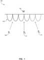
- FIG. 1depicts a wireless communication system 100 including a master wireless node (M) 104 and three slave wireless nodes 108 (S 1 ), 112 (S 2 ), and 116 (S 3 ).
- master wireless noderefers to a node in a wireless communication system that is configured to transmit and receive data from multiple wireless nodes and to transmit commands to control the activities of the other wireless nodes.
- slave wireless noderefers to one of the wireless nodes that is in communication with the master wireless node. The slave wireless nodes typically have an operating mode where each slave wireless node communicates only with the master wireless node.
- the master wireless node 104is configured to transmit data to the slave wireless nodes 108 - 116 using a plurality of orthogonal sub-carriers 120.
- the orthogonal sub-carriers 120are centered at different frequencies in the electromagnetic spectrum to enable the master wireless node 104 to send symbols corresponding to data using each of the orthogonal sub-carriers independently with sufficient attenuation of the other sub-carriers to enable reliable transmission of data symbols at a predetermined transmission rate.
- the master wireless node 108is configured to transmit data symbols to each of the slave wireless nodes 108 - 116 simultaneously using the different orthogonal sub-carriers 120.
- the slave wireless nodes 108 - 116are each configured to receive transmitted symbols from the master wireless node 104 using separate orthogonal sub-carriers 120. In one embodiment, the slave wireless nodes 108-116 also transmit symbols to the master wireless node 104 using either the same sub-carrier 120 that the master 104 uses to transmit to the slave wireless nodes 108 - 116, respectively, or a different orthogonal sub-carrier.
- both the master wireless node 104 and each of the slave wireless nodes 108 - 116include one or more digital controllers, such as digital microprocessors, microcontrollers, digital signal processors, and the like, in addition to radio transceiver hardware and one or more antennas.
- the controllerexecutes stored program instructions portion of the functionality of the radio transceiver in a "software defined radio" embodiment.
- the master wireless node and each of the slave wireless nodesuse a common implementation for hardware and software.
- master wireless node and slave wireless nodeare assigned dynamically through software and a slave wireless node can be reassigned to act as the master wireless node and the master wireless node can change to operate as a slave wireless node. In one configuration, if the master wireless node becomes inoperable, a slave wireless node in the communication system continues operation as the master wireless node to maintain operation of the communication system.
- FIG. 2depicts another wireless communication system configuration 200 in which the master wireless node 104 and the slave wireless nodes 108 - 116 communicate using an interleaved arrangement of orthogonal sub-carriers 220.
- the master wireless node 104communicates with each of the slave wireless nodes 108, 112, and 116 using interleaved orthogonal sub-carriers 208A - 208B, 212A - 212B, and 216A - 216B, respectively.
- the orthogonal sub-carriers 208A - 216Bare said to be interleaved because the frequency ranges of the different orthogonal sub-carriers that are assigned to a given one of the slave wireless nodes 108 - 116 are arranged next to sub-carriers for the other slave wireless nodes in the electromagnetic spectrum.
- the interleaved arrangement of orthogonal sub-carriersprovides additional resistance to noise during operation. For example, if electromagnetic noise in the environment around the system 200 interferes with the sub-carriers 208A and 212A, then the slave wireless nodes 108 and 112 are still able to use the interleaved sub-carriers 208B and 212B, respectively, to communicate with the master wireless node 104.
- the master wireless node 104 and slave wireless nodes 108 - 116can dynamically reallocate sub-carriers based on measured channel and environmental characteristics such as multipath fading.
- the slave wireless nodes 108 - 116 in FIG. 1 and FIG. 2are depicted as having equal sub-carrier and bandwidth allotments, for some applications the slave wireless nodes receive orthogonal sub-carrier allotments with reference to the expected bandwidth requirements for the individual slave wireless nodes. For example, a slave wireless node that aggregates data from multiple industrial devices and transmits the data to the master wireless node is allocated a larger number of orthogonal sub-carriers than another slave wireless node that transmits smaller amounts of data to the master wireless node.
- the master wireless nodeallocates the sub-carriers to the slave devices. In some configurations, the master wireless node adjusts the allocation of sub-carriers to maintain real-time communication with the slave wireless nodes during different operating modes.
- FIG. 3depicts another configuration of a wireless network 300 in which the master wireless node 104 is synchronized in time with the slave wireless nodes 108 - 116.
- the OFDMA implementation in industrial networksincludes synchronization between the master wireless node 104 and the slave wireless nodes 108 - 116 to provide hard real-time communication requirements.
- the master wireless node 104communicates with each of the slave wireless nodes during a comparatively short cycle-time.
- the master wireless node 104synchronizes communications with the slave wireless nodes 108 - 116 using a series of common beacon frames that are transmitted to all of the slave wireless nodes, as depicted in FIG. 3 with the beacon frames 304.
- beacon framerefers to a transmission from the master wireless node to one or more slave wireless nodes that is used to transmit synchronization and command data for the operation of the slave wireless node that are different than the typical transmission data for messages that are sent through the wireless communication system.
- the beacon frameis a broadcast message using all sub-carriers that is sent to all of the slave nodes.
- the beacon frame messagemay also contain data for all nodes at pre-determined locations.
- the common beacon frame methodensures that slave wireless nodes are all synchronized at beginning of each time cycle in a series of predetermined time cycles.
- the single beacon frame synchronization methodleads to simpler design for the master wireless node as the master wireless node is either receiving or transmitting on all sub-carriers.
- FIG. 4depicts another configuration of a wireless network 400 where the master wireless node 104 is synchronized with the slave wireless nodes 108 - 116 using separate beacon frames for each slave wireless node.
- the master wireless node 104sends the individual beacon frames 404, 408, and 412 to the individual slave wireless nodes 108, 112, and 116, respectively, using the corresponding sub-carriers for each of the respective slave wireless nodes.
- the master wireless node 104does not require exact synchronization with all of the slave wireless nodes 108 - 116 to maintain synchronization with any one of the slave wireless nodes 108 - 116.
- FIG. 4depicts another configuration of a wireless network 400 where the master wireless node 104 is synchronized with the slave wireless nodes 108 - 116 using separate beacon frames for each slave wireless node.
- the master wireless node 104sends the individual beacon frames 404, 408, and 412 to the individual slave wireless nodes 108, 112, and 116, respectively, using the corresponding
- the master wireless node 104may be transmitting data using some sub-carriers while simultaneously receiving data using other sub-carriers. Additionally, the configuration of FIG. 4 does not maintain express synchronization between the slave wireless nodes 108 - 116. In one embodiment, the configuration of FIG. 4 is used for systems where master and slave are mutually synchronized but slave wireless nodes are not to be synchronized with each other.
- Some industrial wireless network configurationsrequire synchronization between the master wireless node and the slave wireless nodes and synchronization among the slave wireless nodes.
- the master wireless node 104sends synchronization packets on respective chosen subsets of the sub-carriers for each of the slave wireless nodes 108 - 116 at the same time.
- the master wireless node 104is either listening or transmitting on all sub-carriers at any given time.
- One advantage of this scheme as compared to the one of transmitting common beacon frames for all nodesis possibly a smaller beacon frame size and the master wireless node 104 does not have to transmit on some sub-carriers while receiving on other sub-carriers.
- FIG. 5depicts a series of symbols in a preamble that are transmitted between the master wireless node 104 and slave wireless nodes 108 - 116 in the systems 100 - 400.
- the term "preamble"refers to a set of symbols placed at the beginning of individual data frames to enable the receiving nodes to identify whether a communication message is from another node in the wireless communication system or is a spurious transmission.
- the master wireless node 104 and slave wireless nodes 108 - 116are more tightly coupled than in existing wireless data networks in the unlicensed frequency bands such as IEEE 802.11. Therefore, the requirements for preambles are reduced in the systems 100 - 400.
- a small preamble sequenceassists in identification and rejection of spurious transmissions.
- the preambleincludes a plurality of data symbols, which are referred to as "start symbols.”
- start symbolsIn a wireless communication system with a comparatively small number of sub-carriers, the requirements for complex preambles increase.
- the FIG. 5depicts a preamble sequence where a predetermined preamble sequence of symbols is repeated twice, followed immediately by a copy of uncorrelated symbols.
- a transmitting nodesuch as the master wireless node 104 or slave wireless nodes 108 - 116, transmit a single preamble sequence 504 twice, with no delay between the transmissions of the two preamble sequences 504.
- the transmitting nodethen transmits another portion of the preamble 512, which includes low-correlation symbols that are uncorrelated or have a negative correlation to the symbols in the first portion of the preamble 504.
- the receiving nodeis configured to correlate the repeated preamble sequences 504 to identify a high-correlation, followed by the low-correlation preamble 512, which results in a drop in the correlation for the preamble symbol sequence.
- Such a scenariois uncommon in normal data communication, and the nodes in the wireless communication system use change in the preamble correlation to identify that a message is from another node in the communication network and not a spurious transmission. For example, repetition of the predetermined bit sequence 504 forms two high-correlation sequences of bits in the preamble.
- the low-correlation bit pattern 512is generated through an exclusive-or (XOR) operation of the predetermined bit sequence 504 with a corresponding sequence of logical "1" bits. While the preamble is depicted with the high-correlation bit sequences 504 being transmitted first followed by the low-correlation bit sequence 512, in another embodiment the preamble includes the low-correlation bit sequence 512 followed by the high-correlation bit sequences 504.
- the low-correlation symbolsare selected to be noticeably different than the predetermined pattern of symbols in the high-correlation sequence.
- correlationis used herein with the ordinary meaning of the term as used in signal processing and includes auto-correlation, cross-correlation, and other similar operations operations. More particularly, a cross-correlation between the first and second repetition of the symbols 504 produces a high correlation value (e.g. 1 on a scale of -1 to 1). The cross-correlation of the repeated symbol sequence 504 is also effectively an auto-correlation of the sequence 504 with itself.
- the second symbol sequence 512 in the preambleis generated to have a low correlation value in relative to the sequences 504 in the preamble (e.g.
- the low-correlation symbols in the preamblerefers to a negative correlation to improve detection of the preamble, although in other embodiments the preamble includes a sequence of symbols that are simply uncorrelated to another sequence of high-correlation symbols in the preamble (e.g. 0 on the scale of -1 to 1).
- the high-correlation and low-correlation sequences in the preamblereduce the probability of a false detection of the preamble sequence.
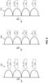
- FIG. 6depicts illustrative symbol transmission configurations for a node, such as the master wireless node 104 or the slave wireless nodes 108 - 116, in the communication systems 100 - 400.
- the wireless nodetransmits and receives 8-bit symbols in each of four sub-carriers, with the wireless node transmitting the same 8-bit symbol to provide redundancy.
- the wireless nodetransmits and receives 2-bit symbols using the four sub-carriers being used to transmit 2-bits of a larger 8-bit byte.
- the wireless nodeis configured to transmit 4-bit symbols using four sub-carriers, where two pairs of sub-carriers each transmit the same 4-bit symbols redundantly to transmit an 8-bit byte across all four sub-carriers.
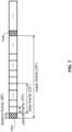
- FIG. 7depicts time slots for transmission of data between master and slave wireless nodes.
- each data packetis transmitted in a packet frame (PF).
- PFpacket frame
- Two or more PFscompose a data frame (DF).
- the same data packetcan be transmitted in multiple PFs within a larger DF.
- One or more DFs and a beacon frame (BF)compose a super frame (SF).
- the master wireless nodetransmits a beacon frame, such as beacon frames 704A and 704B, in each BF.
- the number of PFs in a DF, denoted by NPF, and the number of DFs in a SF, denoted by NDFare configurable and the NPF and NDF numbers are encoded in the beacon frame data.
- a DFmay include of one PF each for all slave wireless nodes, where nodes send their data to the master wireless node. Further, the DF may be repeated several times within the SF for redundancy in wireless network systems that tend to have high rates of packet loss.
- the beacon frame dataalso include transmission powers, transmission rates, sub-carrier assignments and timing & frequency offsets for slave wireless nodes.
- the beacon framefurther contains synchronization packets according to one of the fore mentioned mechanisms.
- slave wireless nodestransmit a preamble and subsequently their data packets through one or more of the assigned sub-carriers.
- the master and slave wireless nodesadd a cyclic prefix (CP) to each sequence of data symbols.
- CPcyclic prefix
- each packet framecorresponds to a fixed-length time slot for transmission of a single set of messages to the slave wireless nodes from the master wireless node where each slave wireless node receives one message. Additionally, one or more of the slave wireless nodes transmits data to the master wireless node during some of the packet frames to enable bidirectional communication.
- the fixed-length packet framesenable the master wireless node to transmit messages of up to a predetermined number of bits to each slave wireless node during a single packet frame. Longer messages are divided amongst multiple packet frames in a data frame, and messages that require even longer transmission times are split amongst data frames in two or more super frames that are defined by periodic transmissions of the beacon frames to synchronize the master and slave wireless nodes.
- each packet framecan include redundantly encoded data that are transmitted using different orthogonal sub-carriers as depicted in FIG. 6 , or the data in the packet frames are optionally transmitted more than once.
- the master wireless node and slave wireless nodescan also use error correction codes (ECC) and other error reducing encoding techniques that are known to the art to reduce the error rate during transmission.
- ECCerror correction codes
- each of the slave nodesBecause the master wireless node transmits the beacon frames at regular intervals to the slave nodes, each of the slave nodes has an opportunity to receive data from the master wireless node and transmit data to the master wireless node during each super frame between the transmissions of the beacon frames. Consequently, each of the nodes in the wireless communication system can communicate during each super frame, which provides a maximum bound on the latency for how long a given wireless node needs to wait before transmitting data.
- the configuration of the master wireless node to transmit beacon frames at different intervals and to control the number and timing of packet frames during each super frameenables adjustment of the maximum latency based on the requirements for communication in the wireless network.
- the master wireless node 104generates two different messages 404 and 408 for the slave wireless nodes 108 and 112, respectively.
- the content of the messages 404 and 408are different for each slave wireless node, but both the messages 404 and 408 are generated with a number of bits that the master wireless node 104 can transmit to the slave wireless nodes 108 and 112 within the period of a single packet frame.
- the master wireless nodegenerates each packet frame for each slave wireless node with a predetermined number of bits, and optionally includes padding bits if the content of a message is less than the number of bits in the packet frame.
- the transmission time for each packet frame to from the master wireless node to each of the slave wireless nodesis substantially equal since the master wireless node begins and ends the transmissions to multiple slave wireless nodes concurrently.
- the predetermined number of bits for a maximum length of a packet framedepends upon the effective rate of symbol transmission to each of the slave wireless nodes over the orthogonal frequency sub-carriers.
- FIG. 8depicts a graph 804 of a transmission scheme for master-to-slave and slave-to-master communication.
- the slave wireless nodescommunicate with the master wireless node during one or more packet frames of a larger super frame.
- the graph 804depicts a configuration where the master wireless node and the slave wireless nodes transmit during one or more of the packet frames.
- the master wireless nodetransmits the beacon frame 808 that includes both synchronization data and command data to control the operation of the slave wireless nodes.
- the beacon frameis sent on all of the available sub-carriers to all of the slave wireless nodes in the wireless communication system. While FIG.
- the master wireless nodetransmits a single beacon frame to all of the slave nodes, in the embodiment of FIG. 4 depicted above the master wireless node transmits separate beacons to individual slave wireless nodes using the allotted orthogonal sub-carriers for each slave wireless node.
- the slave wireless nodestransmit data to the master wireless node during one or more of the packet frames. Since the slave wireless nodes use different orthogonal sub-carriers, multiple slave wireless nodes transmit to the master wireless node during a single packet frame as depicted by the message data 812, 816, and 820, which can be different for each slave wireless node.
- each of the slave wireless nodescan communicate with the master wireless node during a single packet frame.
- Each of the messagesbegins with a preamble, such as the preamble that is depicted in FIG. 5 .
- the master wireless nodealso communications with each of the slave wireless nodes in a similar manner to the slave-to-master communication depicted in FIG. 8 .
- the master wireless nodetransmits during a data frame using the preamble followed by message data for each of the slave wireless nodes using the different orthogonal sub-carriers that are assigned to each slave wireless node to enable the master wireless node to transmit different sets of data to each of the slave wireless nodes during a single packet frame.
- control data that the master wireless controller transmits to the slave wireless nodes in each beacon frameincludes identifiers for the packet frames that the master wireless node has reserved for transmission to the slave wireless nodes and the packet frames that are available for the slave wireless nodes to transmit to the master wireless node to avoid collisions when the master wireless node and the slave wireless nodes transmit simultaneously.
- the master wireless nodecommunicates with the slave wireless nodes using a first set of orthogonal sub-carriers for communication with the slave wireless nodes, and the control data in the beacon frame to the slave wireless nodes includes a second set of orthogonal sub-carriers that the slave wireless nodes use to communicate with the master wireless node.
- the master wireless nodescan transmit to the slave wireless nodes while the slave wireless nodes transmit to the master wireless node concurrently during a single packet frame.
- the master wireless nodesearches preambles that are received from one or more of the slave wireless nodes to identify if one or more of the slave wireless nodes are transmitting during the packet frame.
- the slave wireless nodesuse the preamble sequence including a repeated set of high-correlation bits followed by low-correlation bits that is depicted in FIG. 5 .
- the master wireless nodecalculates frequency and timing offsets of the corresponding slave wireless node in response to identifying the preamble.
- the master wireless nodeuses the identified offsets to compensate for errors in subsequent data symbols. As mentioned above, the offsets are appended on a beacon frame so that slave wireless nodes finely tune their timing and frequency.
- slave wireless nodesalso estimate timing and frequency errors and adapt accordingly to the master wireless node.
- the master wireless nodeAfter receiving preambles, the master wireless node receives data symbols from all sub-carriers and packetizes the data symbols into different packets according to the sub-carrier assignments.
- the master wireless nodeis configured to receive data packets from all slave wireless nodes simultaneously.
Landscapes
- Engineering & Computer Science (AREA)
- Signal Processing (AREA)
- Computer Networks & Wireless Communication (AREA)
- Mobile Radio Communication Systems (AREA)
Description
- This disclosure relates generally to the field of wireless communication and, more specifically, to wireless communication systems that are configured to send messages within real-time communication restraints.
- Real-time communication systems include communication systems that guarantee delivery of communication message data within predetermined time limits. Real-time communication systems are used in a wide range of applications, with industrial control systems being one example where real-time communications are important to the successful operation of manufacturing, control, automation, and other industrial processes.
- Many existing real-time industrial applications use wired communication and specialized protocols to achieve latency and reliability. Wired solutions are, however, expensive and error prone as wired cables are susceptible to electromagnetic interference from the high voltage currents used to drive industrial devices. The wired networks can include several hundred devices controlled by single/multiple controllers. Further, faulty cabling often results in errors that incur costs due to lost productivity and increased maintenance requirements.
- Wireless solutions have the advantage of cleaner and easier installation. Wireless solutions that operate in the lGHz or greater range have reduced susceptibility to electromagnetic interference from most industrial equipment. However, existing wireless communication systems are not suitable for the real-time operational requirements of industrial applications that include real-time communication requirements between multiple devices. For example, existing orthogonal frequency division multiplexing (OFDM) systems employed in standard wireless technologies, such as 802.11g/n, cannot support the strict latency and reliability requirements, although some existing protocols support relaxed soft-real-time requirements using enhancements such as an extension for Quality of Service (QoS) with 802.11e and other medium access protocols. Additionally, OFDM and code division multiple access (CDMA) techniques that are used with cellular data networks are typically unsuitable for use in industrial automation systems due to increased protocol complexity and equipment cost. Consequently, improved systems and methods for wireless communication that enable real-time operation would be beneficial.
- In the published patent prior art the following documents disclose technological background technology for the present invention:
- D1
US 2009/238293 A1 (BHATTI GHULAM [US] ET AL) 24 September 2009 (2009-09-24) - D2
US 2008/107200 A1 (ZHU JIE [US] ET AL) 8 May 2008 (2008-05-08) - D3
WO 2012/088527 A2 (TEXAS INSTRUMENTS INC [US]; TEXAS INSTRUMENTS JAPAN [JP]; KIM TAEJOON) 28 June 2012 (2012-06-28) - The object of the invention is to provide a method and a system for highly reliable real-time wireless communication which reduce the probability of false detection of spurious transmissions.
- This object is solved by a method of
claim 1 and a system ofclaim 8. Further advantageous embodiments and improvements of the invention are listed in the dependent claims. However, before coming to a detailed discussion of such embodiments of the invention with reference to the drawings, below first some general aspects of the invention are discussed which, even if they do not directly refer to the concrete embodiments of the invention in the dependent claims and in the figure description below, give some further insight in features usable in the invention. - A method for wireless communication and a wireless communication system are defined by the appended
independent claims FIG. 1 is a schematic diagram of a wireless communication system.FIG. 2 is another schematic diagram of a wireless communication system.FIG. 3 is another schematic diagram of a wireless communication system.FIG. 4 is another schematic diagram of a wireless communication system.FIG. 5 is a diagram depicting symbols that are used in a preamble to a stream of symbols that are transmitted in a wireless communication system.FIG. 6 is a diagram depicting different symbol sizes for transmission from a node in a wireless communication system.FIG. 7 is a diagram depicting beacon frames and superframes that are used to synchronize wireless data transmissions in a wireless communication system.FIG. 8 is a diagram of beacon frame and packet frame transmission in a wireless communication system.- For the purposes of promoting an understanding of the principles of the embodiments disclosed herein, reference is now be made to the drawings and descriptions in the following written specification. The invention is defined by the appended claims.
- As used herein, the term orthogonal frequency division multiple access (OFDMA) refers to a method of transmitting data in a wireless communication system that includes a plurality of orthogonal sub-carriers that are formed in a larger frequency band of the electromagnetic spectrum. An OFDMA communication system arranges the orthogonal sub-carriers with a sufficient separation in the frequency spectrum between the respective sub-carriers to enable transmission of data symbols through the sub-carriers in an orthogonal manner. That is to say, the attenuation between the frequency bands of the different orthogonal sub-carriers is adequate to enable successful simultaneous transmission of symbols in each of the orthogonal sub-carriers without interference between the orthogonal sub-carriers. As used herein, the term "symbol" refers to a set of data that are communicated over a wireless channel where a radio receiver can decode the symbol into useful information. In one embodiment, a symbol is a single binary bit having two distinct values (e.g. 0 or 1), while other embodiments include more complex symbols including symbols that are represented using multiple bits of binary data. As used herein, the term "message" refers to a sequence of one or more symbols that are transmitted from a master wireless node to a slave wireless node or from a slave wireless node to a master wireless node for data transmission and reception in a wireless radio system.
FIG. 1 depicts awireless communication system 100 including a master wireless node (M) 104 and three slave wireless nodes 108 (S1), 112 (S2), and 116 (S3). As used herein, the term "master wireless node" refers to a node in a wireless communication system that is configured to transmit and receive data from multiple wireless nodes and to transmit commands to control the activities of the other wireless nodes. The term "slave wireless node" refers to one of the wireless nodes that is in communication with the master wireless node. The slave wireless nodes typically have an operating mode where each slave wireless node communicates only with the master wireless node. In the configuration of thesystem 100, the masterwireless node 104 is configured to transmit data to the slave wireless nodes 108 - 116 using a plurality oforthogonal sub-carriers 120. Theorthogonal sub-carriers 120 are centered at different frequencies in the electromagnetic spectrum to enable the masterwireless node 104 to send symbols corresponding to data using each of the orthogonal sub-carriers independently with sufficient attenuation of the other sub-carriers to enable reliable transmission of data symbols at a predetermined transmission rate. In one mode of operation, the masterwireless node 108 is configured to transmit data symbols to each of the slave wireless nodes 108 - 116 simultaneously using the differentorthogonal sub-carriers 120. The slave wireless nodes 108 - 116 are each configured to receive transmitted symbols from the masterwireless node 104 using separateorthogonal sub-carriers 120. In one embodiment, the slave wireless nodes 108-116 also transmit symbols to the masterwireless node 104 using either thesame sub-carrier 120 that themaster 104 uses to transmit to the slave wireless nodes 108 - 116, respectively, or a different orthogonal sub-carrier.- In the example of
FIG. 1 , both the masterwireless node 104 and each of the slave wireless nodes 108 - 116 include one or more digital controllers, such as digital microprocessors, microcontrollers, digital signal processors, and the like, in addition to radio transceiver hardware and one or more antennas. In some embodiments, the controller executes stored program instructions portion of the functionality of the radio transceiver in a "software defined radio" embodiment. In one embodiment, the master wireless node and each of the slave wireless nodes use a common implementation for hardware and software. The roles of master wireless node and slave wireless node are assigned dynamically through software and a slave wireless node can be reassigned to act as the master wireless node and the master wireless node can change to operate as a slave wireless node. In one configuration, if the master wireless node becomes inoperable, a slave wireless node in the communication system continues operation as the master wireless node to maintain operation of the communication system. FIG. 2 depicts another wirelesscommunication system configuration 200 in which the masterwireless node 104 and the slave wireless nodes 108 - 116 communicate using an interleaved arrangement oforthogonal sub-carriers 220. InFIG. 2 , the masterwireless node 104 communicates with each of the slavewireless nodes orthogonal sub-carriers 208A - 208B, 212A - 212B, and 216A - 216B, respectively. Theorthogonal sub-carriers 208A - 216B are said to be interleaved because the frequency ranges of the different orthogonal sub-carriers that are assigned to a given one of the slave wireless nodes 108 - 116 are arranged next to sub-carriers for the other slave wireless nodes in the electromagnetic spectrum. The interleaved arrangement of orthogonal sub-carriers provides additional resistance to noise during operation. For example, if electromagnetic noise in the environment around thesystem 200 interferes with thesub-carriers slave wireless nodes sub-carriers master wireless node 104.- In any configuration of wireless communications, the
master wireless node 104 and slave wireless nodes 108 - 116 can dynamically reallocate sub-carriers based on measured channel and environmental characteristics such as multipath fading. Additionally, while the slave wireless nodes 108 - 116 inFIG. 1 andFIG. 2 are depicted as having equal sub-carrier and bandwidth allotments, for some applications the slave wireless nodes receive orthogonal sub-carrier allotments with reference to the expected bandwidth requirements for the individual slave wireless nodes. For example, a slave wireless node that aggregates data from multiple industrial devices and transmits the data to the master wireless node is allocated a larger number of orthogonal sub-carriers than another slave wireless node that transmits smaller amounts of data to the master wireless node. In one embodiment, the master wireless node allocates the sub-carriers to the slave devices. In some configurations, the master wireless node adjusts the allocation of sub-carriers to maintain real-time communication with the slave wireless nodes during different operating modes. FIG. 3 depicts another configuration of awireless network 300 in which themaster wireless node 104 is synchronized in time with the slave wireless nodes 108 - 116. In some embodiments, the OFDMA implementation in industrial networks includes synchronization between themaster wireless node 104 and the slave wireless nodes 108 - 116 to provide hard real-time communication requirements. In some operating modes, themaster wireless node 104 communicates with each of the slave wireless nodes during a comparatively short cycle-time. In one embodiment, themaster wireless node 104 synchronizes communications with the slave wireless nodes 108 - 116 using a series of common beacon frames that are transmitted to all of the slave wireless nodes, as depicted inFIG. 3 with the beacon frames 304. The term "beacon frame" refers to a transmission from the master wireless node to one or more slave wireless nodes that is used to transmit synchronization and command data for the operation of the slave wireless node that are different than the typical transmission data for messages that are sent through the wireless communication system. The beacon frame is a broadcast message using all sub-carriers that is sent to all of the slave nodes. The beacon frame message may also contain data for all nodes at pre-determined locations. The common beacon frame method ensures that slave wireless nodes are all synchronized at beginning of each time cycle in a series of predetermined time cycles. In addition, the single beacon frame synchronization method leads to simpler design for the master wireless node as the master wireless node is either receiving or transmitting on all sub-carriers.FIG. 4 depicts another configuration of awireless network 400 where themaster wireless node 104 is synchronized with the slave wireless nodes 108 - 116 using separate beacon frames for each slave wireless node. InFIG. 4 , themaster wireless node 104 sends the individual beacon frames 404, 408, and 412 to the individualslave wireless nodes FIG. 4 , themaster wireless node 104 does not require exact synchronization with all of the slave wireless nodes 108 - 116 to maintain synchronization with any one of the slave wireless nodes 108 - 116. In the configuration ofFIG. 4 , themaster wireless node 104 may be transmitting data using some sub-carriers while simultaneously receiving data using other sub-carriers. Additionally, the configuration ofFIG. 4 does not maintain express synchronization between the slave wireless nodes 108 - 116. In one embodiment, the configuration ofFIG. 4 is used for systems where master and slave are mutually synchronized but slave wireless nodes are not to be synchronized with each other.- Some industrial wireless network configurations require synchronization between the master wireless node and the slave wireless nodes and synchronization among the slave wireless nodes. In another configuration, the
master wireless node 104 sends synchronization packets on respective chosen subsets of the sub-carriers for each of the slave wireless nodes 108 - 116 at the same time. In this configuration, themaster wireless node 104 is either listening or transmitting on all sub-carriers at any given time. One advantage of this scheme as compared to the one of transmitting common beacon frames for all nodes is possibly a smaller beacon frame size and themaster wireless node 104 does not have to transmit on some sub-carriers while receiving on other sub-carriers. FIG. 5 depicts a series of symbols in a preamble that are transmitted between themaster wireless node 104 and slave wireless nodes 108 - 116 in the systems 100 - 400. The term "preamble" refers to a set of symbols placed at the beginning of individual data frames to enable the receiving nodes to identify whether a communication message is from another node in the wireless communication system or is a spurious transmission. In the systems 100 - 400, themaster wireless node 104 and slave wireless nodes 108 - 116 are more tightly coupled than in existing wireless data networks in the unlicensed frequency bands such as IEEE 802.11. Therefore, the requirements for preambles are reduced in the systems 100 - 400. However, in wireless communication networks that operate in unlicensed frequency bands, such as the 2.4 GHz and 5 GHz bands, a small preamble sequence assists in identification and rejection of spurious transmissions.- The preamble includes a plurality of data symbols, which are referred to as "start symbols." In a wireless communication system with a comparatively small number of sub-carriers, the requirements for complex preambles increase. To reduce the number of symbols that are required for use in a preamble, the
FIG. 5 depicts a preamble sequence where a predetermined preamble sequence of symbols is repeated twice, followed immediately by a copy of uncorrelated symbols. InFIG. 5 , a transmitting node, such as themaster wireless node 104 or slave wireless nodes 108 - 116, transmit asingle preamble sequence 504 twice, with no delay between the transmissions of the twopreamble sequences 504. The transmitting node then transmits another portion of thepreamble 512, which includes low-correlation symbols that are uncorrelated or have a negative correlation to the symbols in the first portion of thepreamble 504. The receiving node is configured to correlate the repeatedpreamble sequences 504 to identify a high-correlation, followed by the low-correlation preamble 512, which results in a drop in the correlation for the preamble symbol sequence. Such a scenario is uncommon in normal data communication, and the nodes in the wireless communication system use change in the preamble correlation to identify that a message is from another node in the communication network and not a spurious transmission. For example, repetition of thepredetermined bit sequence 504 forms two high-correlation sequences of bits in the preamble. In one embodiment, the low-correlation bit pattern 512 is generated through an exclusive-or (XOR) operation of thepredetermined bit sequence 504 with a corresponding sequence of logical "1" bits. While the preamble is depicted with the high-correlation bit sequences 504 being transmitted first followed by the low-correlation bit sequence 512, in another embodiment the preamble includes the low-correlation bit sequence 512 followed by the high-correlation bit sequences 504. - The low-correlation symbols are selected to be noticeably different than the predetermined pattern of symbols in the high-correlation sequence. The term "correlation" is used herein with the ordinary meaning of the term as used in signal processing and includes auto-correlation, cross-correlation, and other similar operations operations. More particularly, a cross-correlation between the first and second repetition of the
symbols 504 produces a high correlation value (e.g. 1 on a scale of -1 to 1). The cross-correlation of the repeatedsymbol sequence 504 is also effectively an auto-correlation of thesequence 504 with itself. Thesecond symbol sequence 512 in the preamble is generated to have a low correlation value in relative to thesequences 504 in the preamble (e.g. -1 on the scale of -1 to 1). In the illustrative embodiment, the low-correlation symbols in the preamble refers to a negative correlation to improve detection of the preamble, although in other embodiments the preamble includes a sequence of symbols that are simply uncorrelated to another sequence of high-correlation symbols in the preamble (e.g. 0 on the scale of -1 to 1). The high-correlation and low-correlation sequences in the preamble reduce the probability of a false detection of the preamble sequence. FIG. 6 depicts illustrative symbol transmission configurations for a node, such as themaster wireless node 104 or the slave wireless nodes 108 - 116, in the communication systems 100 - 400. In theconfiguration 604, the wireless node transmits and receives 8-bit symbols in each of four sub-carriers, with the wireless node transmitting the same 8-bit symbol to provide redundancy. In theconfiguration 608, the wireless node transmits and receives 2-bit symbols using the four sub-carriers being used to transmit 2-bits of a larger 8-bit byte. In theconfiguration 612, the wireless node is configured to transmit 4-bit symbols using four sub-carriers, where two pairs of sub-carriers each transmit the same 4-bit symbols redundantly to transmit an 8-bit byte across all four sub-carriers.FIG. 7 depicts time slots for transmission of data between master and slave wireless nodes. InFIG. 7 andFIG. 8 , each data packet is transmitted in a packet frame (PF). Two or more PFs compose a data frame (DF). The same data packet can be transmitted in multiple PFs within a larger DF. One or more DFs and a beacon frame (BF) compose a super frame (SF). The master wireless node transmits a beacon frame, such as beacon frames 704A and 704B, in each BF. The number of PFs in a DF, denoted by NPF, and the number of DFs in a SF, denoted by NDF, are configurable and the NPF and NDF numbers are encoded in the beacon frame data. As an example, a DF may include of one PF each for all slave wireless nodes, where nodes send their data to the master wireless node. Further, the DF may be repeated several times within the SF for redundancy in wireless network systems that tend to have high rates of packet loss. The beacon frame data also include transmission powers, transmission rates, sub-carrier assignments and timing & frequency offsets for slave wireless nodes. The beacon frame further contains synchronization packets according to one of the fore mentioned mechanisms. In a PF, slave wireless nodes transmit a preamble and subsequently their data packets through one or more of the assigned sub-carriers. To eliminate timing errors, the master and slave wireless nodes add a cyclic prefix (CP) to each sequence of data symbols.- As depicted in
FIG. 7 , each packet frame corresponds to a fixed-length time slot for transmission of a single set of messages to the slave wireless nodes from the master wireless node where each slave wireless node receives one message. Additionally, one or more of the slave wireless nodes transmits data to the master wireless node during some of the packet frames to enable bidirectional communication. The fixed-length packet frames enable the master wireless node to transmit messages of up to a predetermined number of bits to each slave wireless node during a single packet frame. Longer messages are divided amongst multiple packet frames in a data frame, and messages that require even longer transmission times are split amongst data frames in two or more super frames that are defined by periodic transmissions of the beacon frames to synchronize the master and slave wireless nodes. As described above, the transmission of data can include redundancy at multiple levels to improve the reliability of communication in environments that are subjected to noise and other interference. For example, each packet frame can include redundantly encoded data that are transmitted using different orthogonal sub-carriers as depicted inFIG. 6 , or the data in the packet frames are optionally transmitted more than once. The master wireless node and slave wireless nodes can also use error correction codes (ECC) and other error reducing encoding techniques that are known to the art to reduce the error rate during transmission. - Because the master wireless node transmits the beacon frames at regular intervals to the slave nodes, each of the slave nodes has an opportunity to receive data from the master wireless node and transmit data to the master wireless node during each super frame between the transmissions of the beacon frames. Consequently, each of the nodes in the wireless communication system can communicate during each super frame, which provides a maximum bound on the latency for how long a given wireless node needs to wait before transmitting data. The configuration of the master wireless node to transmit beacon frames at different intervals and to control the number and timing of packet frames during each super frame enables adjustment of the maximum latency based on the requirements for communication in the wireless network.
- For example, in one configuration the
master wireless node 104 generates twodifferent messages slave wireless nodes messages messages master wireless node 104 can transmit to theslave wireless nodes FIG. 8 depicts agraph 804 of a transmission scheme for master-to-slave and slave-to-master communication. In thegraph 804, the slave wireless nodes communicate with the master wireless node during one or more packet frames of a larger super frame. Thegraph 804 depicts a configuration where the master wireless node and the slave wireless nodes transmit during one or more of the packet frames. As depicted in thegraph 804, the master wireless node transmits the beacon frame 808 that includes both synchronization data and command data to control the operation of the slave wireless nodes. The beacon frame is sent on all of the available sub-carriers to all of the slave wireless nodes in the wireless communication system. WhileFIG. 8 depicts an embodiment where the master wireless node transmits a single beacon frame to all of the slave nodes, in the embodiment ofFIG. 4 depicted above the master wireless node transmits separate beacons to individual slave wireless nodes using the allotted orthogonal sub-carriers for each slave wireless node. In thegraph 804, the slave wireless nodes transmit data to the master wireless node during one or more of the packet frames. Since the slave wireless nodes use different orthogonal sub-carriers, multiple slave wireless nodes transmit to the master wireless node during a single packet frame as depicted by themessage data FIG. 5 .- The master wireless node also communications with each of the slave wireless nodes in a similar manner to the slave-to-master communication depicted in
FIG. 8 . In particular, the master wireless node transmits during a data frame using the preamble followed by message data for each of the slave wireless nodes using the different orthogonal sub-carriers that are assigned to each slave wireless node to enable the master wireless node to transmit different sets of data to each of the slave wireless nodes during a single packet frame. In one embodiment, the control data that the master wireless controller transmits to the slave wireless nodes in each beacon frame includes identifiers for the packet frames that the master wireless node has reserved for transmission to the slave wireless nodes and the packet frames that are available for the slave wireless nodes to transmit to the master wireless node to avoid collisions when the master wireless node and the slave wireless nodes transmit simultaneously. In another embodiment, the master wireless node communicates with the slave wireless nodes using a first set of orthogonal sub-carriers for communication with the slave wireless nodes, and the control data in the beacon frame to the slave wireless nodes includes a second set of orthogonal sub-carriers that the slave wireless nodes use to communicate with the master wireless node. In an embodiment where the master-to-slave and slave-to-master communications use different sets of orthogonal sub-carriers, the master wireless nodes can transmit to the slave wireless nodes while the slave wireless nodes transmit to the master wireless node concurrently during a single packet frame. - During each packet frame, the master wireless node searches preambles that are received from one or more of the slave wireless nodes to identify if one or more of the slave wireless nodes are transmitting during the packet frame. In one embodiment, the slave wireless nodes use the preamble sequence including a repeated set of high-correlation bits followed by low-correlation bits that is depicted in
FIG. 5 . The master wireless node calculates frequency and timing offsets of the corresponding slave wireless node in response to identifying the preamble. The master wireless node uses the identified offsets to compensate for errors in subsequent data symbols. As mentioned above, the offsets are appended on a beacon frame so that slave wireless nodes finely tune their timing and frequency. Further, slave wireless nodes also estimate timing and frequency errors and adapt accordingly to the master wireless node. After receiving preambles, the master wireless node receives data symbols from all sub-carriers and packetizes the data symbols into different packets according to the sub-carrier assignments. Thus, the master wireless node is configured to receive data packets from all slave wireless nodes simultaneously.
Claims (16)
- A method for wireless communication, comprising:a) generating by a first controller in a master wireless node (104) a first allotment of sub-carriers (120; 220) selected from a predetermined frequency band for communication with a first slave wireless node (108, 112, 116), the first allotment of sub-carriers including at least two orthogonal sub-carriers;b) generating by the first controller in the master wireless node (104) a second allotment of sub-carriers selected from the predetermined frequency band for communication with a second slave wireless node (108, 112, 116), the second allotment of sub-carriers including at least two orthogonal sub-carriers that are different than the at least two orthogonal sub-carriers in the first allotment of sub-carriers (120; 220);c) transmitting by a first transceiver in the master wireless node (104) a first message to the first slave wireless node using only the first allotment of sub-carriers and a second message to the second slave wireless node using only the second allotment of sub-carriers, the first message being different than the second message and the transmission of the first message and the second message occurring concurrently;d) generating by a second controller in the first slave wireless node a third message for transmission to the master wireless node; ande) transmitting by a second transceiver in the first slave wireless node a preamble to the master wireless node followed immediately by the third message using the first allotment of sub-carriers; andf) the transmission of the preamble further comprises transmitting by the second transceiver in the first slave wireless node the preamble including a first predetermined sequence (504) of symbols followed immediately with no delay by a repetition of the first predetermined sequence (504) of symbols and a second predetermined sequence (512) of symbols having a low correlation to the first predetermined sequence (504) of symbols, the preamble including the low correlation second predetermined sequence of symbols (512) immediately followed by the first predetermined sequence (504) and its repetition (504); andg) the master wireless node (104) receiving the preamble and correlating the received predetermined sequences (504; 512) to identify a drop in correlation of a cross-correlation with a low correlation value of the second predetermined sequence (512) relative to the first predetermined sequences (504) and an auto-correlation with a high correlation value of the first predetermined sequence (504) with itself, the low correlation value (e.g. -1) being smaller than the high correlation value (e.g. 1).
- The method of claim 1, wherein generating, by the first controller in the master wireless node, the first allotment of sub-carriers further comprises:
selecting by the first controller in the master wireless node two sub-carriers for the first allotment of sub-carriers in the predetermined frequency band having a plurality of sub-carriers in which a first sub-carrier in the first allotment of sub-carriers is separated from a second sub-carrier in the first allotment of sub-carriers by at least one other sub-carrier in the plurality of sub-carriers in the predetermined frequency band. - The method of claim 2, wherein generating, by the first controller in the master wireless node, the second allotment of sub-carriers further comprises:
selecting by the first controller in the master wireless node the at least one other sub-carrier in the plurality of sub-carriers that separates the first sub-carrier in the first allotment of sub-carriers and the second sub-carrier in the first allotment of sub-carriers as one of the sub-carriers for the second allotment of sub-carriers. - The method of claim 2, further comprising:
transmitting by the first transceiver in the master wireless node the first message and the second message with a transmission time for the first message and the second message being concurrent. - The method of claim 1, further comprising:generating by the first controller in the master wireless node a beacon frame; andtransmitting by the first transceiver in the master wireless node the beacon frame to the first slave wireless node and the second slave wireless node using both the first allotment of sub-carriers and the second allotment of sub-carriers to synchronize the first slave wireless node and the second slave wireless node.
- The method of claim 1, further comprising:generating by a third controller in the second slave wireless node a fourth message for transmission to the master wireless node; andtransmitting by a third transceiver in the second slave wireless node the preamble to the master wireless node followed immediately by the fourth message using the second allotment of sub-carriers, the transmitting of the fourth message by the second slave wireless node occurring substantially simultaneously to the transmission of the third message by the first slave wireless node.
- The method of claim 1, wherein transmitting, by the first transceiver in the master wireless node, the first message from the master wireless node to the first slave wireless node further comprises:
transmitting by the first transceiver in the master wireless node a first symbol in the first message using both a first orthogonal sub-carrier and a second orthogonal sub-carrier in the at least two orthogonal sub-carriers of the first allotment to the first slave wireless node. - The method of claim 1, wherein the second sequence has a low-correlation bit pattern (512) generated through an exclusive-or, XOR, operation of the bit sequence of the first sequence (504) with a corresponding sequence of logical "1" bits.
- A wireless communication system, comprising:a) a first slave wireless node;b) a second slave wireless node; andc) a master wireless node, wherein the master wireless node comprises:c1) a first transceiver configured to transmit data to the first slave wireless node and the second slave wireless node and receive data from the first slave wireless node and the second slave wireless node; andc2) a first controller operatively connected to the first transceiver, wherein the first controller is configured to:c21) generate a first allotment of sub-carriers selected from a predetermined frequency band for communication with the first slave wireless node, the first allotment of sub-carriers including at least two orthogonal sub-carriers;c22) generate a second of allotment of sub-carriers selected from the predetermined frequency band for communication with the second slave wireless node, the second allotment of sub-carriers including at least two orthogonal sub-carriers that are different than the at least two orthogonal sub-carriers in the first allotment of sub-carriers; andc23) transmit a first message to the first slave wireless node using only the first allotment of sub-carriers and a second message to the second slave wireless node using only the second allotment of sub-carriers, the first message being different than the second message and the transmission of the first message and the second message occurring concurrently; whereind) the first slave node further comprises:d1) a second transceiver configured to transmit data to the master wireless node and receive data from the master wireless node; andd2) a second controller operatively connected to the second transceiver, wherein the second controller is configured to:d21) generate a third message for transmission to the master wireless node; andd22) transmit a preamble to the master wireless node followed immediately by the third message using the first allotment of sub-carriers;d3) the second controller is further configured to transmit the preamble including a first predetermined sequence of symbols followed immediately with no delay by a repetition of the first predetermined sequence of symbols and ia second predetermined sequence of symbols having a low correlation to the first predetermined sequence of symbols, the preamble including the low correlation second predetermined sequence of symbols (512) immediately followed by the first ptedetermined sequence (504) and its repetition (504); ande) the master wireless node (104) configured to receive the preamble and correlate the received predetermined sequences (504; 512) to identify a drop in correlation of a cross-correlation with a low correlation value of the second predetermined sequence (512) relative to the first predetermined sequences (504) and an auto-correlation with a high correlation value of the first predetermined sequence (504) with itself, the low correlation value (e.g. -1) being smaller than the high correlation value (e.g. 1).
- The system of claim 9, wherein the first controller is further configured to:
select two sub-carriers for the first allotment in the predetermined frequency band having a plurality of sub-carriers in which a first sub-carrier in the first allotment of sub-carriers is separated from a second sub-carrier in the first allotment of sub-carriers by at least one other sub-carrier in the plurality of sub-carriers in the predetermined frequency band. - The system of claim 10, wherein the first controller is further configured to:
select the at least one other sub-carrier in the plurality of sub-carriers that separates the first sub-carrier in the first allotment of sub-carriers and the second sub-carrier in the first allotment of sub-carriers as one of the sub-carriers for the second allotment of sub-carriers. - The system of claim 10, wherein the first controller is further configured to:
transmit the first message and the second message with a transmission time for the first message and the second message being concurrent. - The system of claim 9, wherein the first controller is further configured to:generate a beacon frame; andtransmit the beacon frame to the first slave wireless node and the second slave wireless node using both the first allotment of sub-carriers and the second allotment of sub-carriers to synchronize the first slave wireless node and the second slave wireless node.
- The system of claim 9,
wherein the second slave wireless node further comprises:a third transceiver configured to transmit data to the master wireless node and receive data from the master wireless node; anda third controller operatively connected to the third transceiver, wherein the third controller is configured to:generate a fourth message for transmission to the master wireless node; andtransmit the preamble to the master wireless node followed immediately by the fourth message using the second allotment of sub-carriers, the transmitting of the fourth message by the second slave wireless node occurring simultaneously to the transmission of the third message by the first slave wireless node. - The system of claim 9, wherein the first controller is further configured to:
transmit a first symbol in the first message using both a first orthogonal sub-carrier and a second orthogonal sub-carrier in the at least two orthogonal sub-carriers of the first allotment of sub-carriers. - The system of claim 9,
wherein the second sequence has a low-correlation bit pattern (512) generated through an exclusive-or, XOR, operation of the bit sequence of the first sequence (504) with a corresponding sequence of logical "1" bits.
Applications Claiming Priority (2)
| Application Number | Priority Date | Filing Date | Title |
|---|---|---|---|
| US201361788389P | 2013-03-15 | 2013-03-15 | |
| PCT/US2014/027327WO2014152424A1 (en) | 2013-03-15 | 2014-03-14 | Method for robust real-time wireless industrial communication |
Publications (3)
| Publication Number | Publication Date |
|---|---|
| EP2974186A1 EP2974186A1 (en) | 2016-01-20 |
| EP2974186A4 EP2974186A4 (en) | 2016-11-09 |
| EP2974186B1true EP2974186B1 (en) | 2023-06-28 |
Family
ID=51526779
Family Applications (1)
| Application Number | Title | Priority Date | Filing Date |
|---|---|---|---|
| EP14769300.6AActiveEP2974186B1 (en) | 2013-03-15 | 2014-03-14 | Method and system for robust real-time wireless industrial communication |
Country Status (3)
| Country | Link |
|---|---|
| US (1) | US9439194B2 (en) |
| EP (1) | EP2974186B1 (en) |
| WO (1) | WO2014152424A1 (en) |
Families Citing this family (8)
| Publication number | Priority date | Publication date | Assignee | Title |
|---|---|---|---|---|
| US9713035B2 (en) | 2013-05-20 | 2017-07-18 | Qualcomm Incorporated | Beacon transmission over unlicensed spectrum |
| US10034179B2 (en) | 2013-10-30 | 2018-07-24 | Sai C. Manapragada | System and method for extending range and coverage of bandwidth intensive wireless data streams |
| EP3494681B1 (en)* | 2016-08-10 | 2021-06-30 | Huawei Technologies Co., Ltd. | Common synchronization signal for a new radio carrier supporting different subcarrier spacing |
| CN109991899A (en)* | 2019-04-01 | 2019-07-09 | 上海电气泰雷兹交通自动化系统有限公司 | Half dynamic synchronization method of data between the active and standby controller of Rail Transit System |
| JP6875569B2 (en)* | 2020-01-30 | 2021-05-26 | パナソニック インテレクチュアル プロパティ コーポレーション オブ アメリカPanasonic Intellectual Property Corporation of America | User device and random access method |
| CN112235074B (en)* | 2020-08-25 | 2021-11-09 | 北京邮电大学 | High-fault-tolerance frame synchronization information extraction method |
| CN113114601B (en)* | 2021-04-06 | 2022-03-18 | 上海纵行企业发展有限公司 | Receiver based on M-FSK modulation and receiving method thereof |
| US12342302B2 (en)* | 2022-10-25 | 2025-06-24 | Zebra Technologies Corporation | Devices and methods for synchronizing transceiver devices to simultaneously capture data across multiple advertisement channels |
Family Cites Families (22)
| Publication number | Priority date | Publication date | Assignee | Title |
|---|---|---|---|---|
| US6311068B1 (en) | 1998-10-19 | 2001-10-30 | At&T Corp. | Method and apparatus for a high-capacity cellular network by improved sectorization and interleaved channel assignment |
| ES2186531B1 (en)* | 2001-04-19 | 2005-03-16 | Diseño De Sistemas En Silicio, S.A. | PROCEDURE FOR MULTIPLE AND MULTIPLE DATA TRANSMISSION FOR A MULTI-USER DIGITAL DATA TRANSMISSION SYSTEM POINT TO MULTIPOINT ON ELECTRICAL NETWORK. |
| US8331377B2 (en)* | 2004-05-05 | 2012-12-11 | Qualcomm Incorporated | Distributed forward link schedulers for multi-carrier communication systems |
| US7835339B1 (en) | 2005-03-31 | 2010-11-16 | Avaya Inc. | Dynamic channel assignment in wireless ad hoc networks |
| US9225416B2 (en)* | 2005-10-27 | 2015-12-29 | Qualcomm Incorporated | Varied signaling channels for a reverse link in a wireless communication system |
| US8130629B2 (en)* | 2005-11-25 | 2012-03-06 | Go Net Systems Ltd | Simultaneous simulcast and single cast hybrid multi-tone communication system |
| KR101285014B1 (en)* | 2006-03-14 | 2013-07-10 | 삼성전자주식회사 | Apparatus and method for allocating resource and communicating in wireless communication system thereof |
| US8738056B2 (en) | 2006-05-22 | 2014-05-27 | Qualcomm Incorporation | Signal acquisition in a wireless communication system |
| US20080107200A1 (en)* | 2006-11-07 | 2008-05-08 | Telecis Wireless, Inc. | Preamble detection and synchronization in OFDMA wireless communication systems |
| US8160189B2 (en) | 2007-01-26 | 2012-04-17 | Raytheon Company | Method and system for communication channel characterization |
| US8625568B2 (en)* | 2007-09-21 | 2014-01-07 | Lg Electronics Inc. | Method of mapping physical resource to logical resource in wireless communication system |
| US20090150537A1 (en) | 2007-12-10 | 2009-06-11 | John Fanson | Data communication method for a set of hard-real time applications within a network |
| US8218661B2 (en) | 2008-03-18 | 2012-07-10 | Mitsubishi Electric Research Laboratories, Inc. | OFDMA based medium access control and frame structure design for industrial applications |
| IL190659A0 (en)* | 2008-04-07 | 2008-12-29 | Mariana Goldhamer | Wireless communication network with relay stations |
| EP2342877B1 (en) | 2008-08-26 | 2013-03-27 | Marvell World Trade Ltd. | Physical layer data unit format |
| US8730853B2 (en) | 2008-09-05 | 2014-05-20 | Mediatek Inc. | Methods for responding to co-located coexistence (CLC) request from a mobile electronic device and communications apparatuses capable of controlling multi-radio coexistence |
| JP5202247B2 (en) | 2008-11-25 | 2013-06-05 | キヤノン株式会社 | COMMUNICATION SYSTEM, COMMUNICATION DEVICE, AND COMMUNICATION METHOD |
| JP2010258599A (en) | 2009-04-22 | 2010-11-11 | Sony Corp | Wireless communication apparatus, wireless communication method, computer program, and wireless communication system |
| CN102025478B (en)* | 2009-09-15 | 2015-03-18 | 华为技术有限公司 | Method and device for transmitting and receiving data |
| DE102010012330A1 (en) | 2010-03-23 | 2011-09-29 | Robert Bosch Gmbh | Transmission system and transmission method for the wireless transmission of signals in an automation system and automation system with such a transmission system |
| JP5691016B2 (en) | 2010-11-10 | 2015-04-01 | パナソニックIpマネジメント株式会社 | Wireless communication system, wireless terminal, and program |
| US8767848B2 (en)* | 2010-12-23 | 2014-07-01 | Texas Instruments Incorporated | Channel estimation based on long training symbol with doubled cyclic prefix |
- 2014
- 2014-03-14EPEP14769300.6Apatent/EP2974186B1/enactiveActive
- 2014-03-14USUS14/210,864patent/US9439194B2/enactiveActive
- 2014-03-14WOPCT/US2014/027327patent/WO2014152424A1/enactiveApplication Filing
Also Published As
| Publication number | Publication date |
|---|---|
| EP2974186A4 (en) | 2016-11-09 |
| US9439194B2 (en) | 2016-09-06 |
| US20140269560A1 (en) | 2014-09-18 |
| EP2974186A1 (en) | 2016-01-20 |
| WO2014152424A1 (en) | 2014-09-25 |
Similar Documents
| Publication | Publication Date | Title |
|---|---|---|
| EP2974186B1 (en) | Method and system for robust real-time wireless industrial communication | |
| US11070247B2 (en) | Optimized hopping patterns for different sensor nodes and variable data lengths on the basis of the telegram splitting transmission method | |
| CN115276734B (en) | Transmission structure and format of downlink control channel | |
| CN109150424B (en) | Reference signal, message transmission method, transmission resource determination method and device | |
| CN106658584B (en) | Method and apparatus for signal transmission and reception and interference measurement | |
| EP3281353B1 (en) | Method and equipment for channel sensing and signal transmission | |
| US20050176371A1 (en) | Synchronization of time-frequency codes | |
| US20170257139A1 (en) | Hopping synchronization signals | |
| KR20090084407A (en) | Apparatus and method for data transmission in wireless communication system | |
| US8774088B2 (en) | Legacy operations in a MU MIMO wireless network | |
| US9370008B2 (en) | Data resource mapping for frequency-coded symbols | |
| US10251185B2 (en) | Allocating partially overlapping resources to communication devices | |
| TW201541890A (en) | Master station and method for HEW communication using a transmission signaling structure for a HEW signal field | |
| CN108023702A (en) | Data transmission method and device in a kind of cordless communication network | |
| US20190014198A1 (en) | Telegram Splitting for Slotted ALOHA | |
| KR20190017562A (en) | Method and apparatus for transmitting and receiving demodulation reference signal for nr system | |
| US20200045679A1 (en) | Configuring Wireless Communications Resources | |
| US20130163567A1 (en) | Transmission System and Transmission Method for the Wireless Transmission of Signals in an Automation Installation, and Automation Installation having such a Transmission System | |
| EP4101220B1 (en) | Transmitting data in unlicensed spectrum | |
| CN102763357A (en) | Base station and method of adjusting reference timing on base station | |
| WO2022008068A1 (en) | Measurement signals for sensing | |
| CN107210878B (en) | Pilot patterns for WIFI OFDMA | |
| Shao et al. | LiCo: Toward Lightweight Resolution of Signal Collisions in LoRaWAN |
Legal Events
| Date | Code | Title | Description |
|---|---|---|---|
| PUAI | Public reference made under article 153(3) epc to a published international application that has entered the european phase | Free format text:ORIGINAL CODE: 0009012 | |
| 17P | Request for examination filed | Effective date:20151015 | |
| AK | Designated contracting states | Kind code of ref document:A1 Designated state(s):AL AT BE BG CH CY CZ DE DK EE ES FI FR GB GR HR HU IE IS IT LI LT LU LV MC MK MT NL NO PL PT RO RS SE SI SK SM TR | |
| AX | Request for extension of the european patent | Extension state:BA ME | |
| DAX | Request for extension of the european patent (deleted) | ||
| A4 | Supplementary search report drawn up and despatched | Effective date:20161007 | |
| RIC1 | Information provided on ipc code assigned before grant | Ipc:H04L 12/911 20130101AFI20160930BHEP Ipc:H04L 5/00 20060101ALI20160930BHEP Ipc:H04L 27/26 20060101ALI20160930BHEP | |
| STAA | Information on the status of an ep patent application or granted ep patent | Free format text:STATUS: EXAMINATION IS IN PROGRESS | |
| 17Q | First examination report despatched | Effective date:20191010 | |
| RAP1 | Party data changed (applicant data changed or rights of an application transferred) | Owner name:ROBERT BOSCH GMBH | |
| REG | Reference to a national code | Ref country code:DE Ref legal event code:R079 Ref document number:602014087466 Country of ref document:DE Free format text:PREVIOUS MAIN CLASS: H04L0012911000 Ipc:H04L0005000000 Ref country code:DE Ref legal event code:R079 Free format text:PREVIOUS MAIN CLASS: H04L0012911000 Ipc:H04L0005000000 | |
| GRAJ | Information related to disapproval of communication of intention to grant by the applicant or resumption of examination proceedings by the epo deleted | Free format text:ORIGINAL CODE: EPIDOSDIGR1 | |
| GRAP | Despatch of communication of intention to grant a patent | Free format text:ORIGINAL CODE: EPIDOSNIGR1 | |
| GRAP | Despatch of communication of intention to grant a patent | Free format text:ORIGINAL CODE: EPIDOSNIGR1 | |
| STAA | Information on the status of an ep patent application or granted ep patent | Free format text:STATUS: GRANT OF PATENT IS INTENDED | |
| RIC1 | Information provided on ipc code assigned before grant | Ipc:H04L 27/26 20060101ALI20230126BHEP Ipc:H04L 5/00 20060101AFI20230126BHEP | |
| INTG | Intention to grant announced | Effective date:20230209 | |
| GRAS | Grant fee paid | Free format text:ORIGINAL CODE: EPIDOSNIGR3 | |
| GRAA | (expected) grant | Free format text:ORIGINAL CODE: 0009210 | |
| STAA | Information on the status of an ep patent application or granted ep patent | Free format text:STATUS: THE PATENT HAS BEEN GRANTED | |
| AK | Designated contracting states | Kind code of ref document:B1 Designated state(s):AL AT BE BG CH CY CZ DE DK EE ES FI FR GB GR HR HU IE IS IT LI LT LU LV MC MK MT NL NO PL PT RO RS SE SI SK SM TR | |
| REG | Reference to a national code | Ref country code:CH Ref legal event code:EP | |
| REG | Reference to a national code | Ref country code:AT Ref legal event code:REF Ref document number:1583700 Country of ref document:AT Kind code of ref document:T Effective date:20230715 | |
| REG | Reference to a national code | Ref country code:IE Ref legal event code:FG4D | |
| REG | Reference to a national code | Ref country code:DE Ref legal event code:R096 Ref document number:602014087466 Country of ref document:DE | |
| REG | Reference to a national code | Ref country code:LT Ref legal event code:MG9D | |
| PG25 | Lapsed in a contracting state [announced via postgrant information from national office to epo] | Ref country code:SE Free format text:LAPSE BECAUSE OF FAILURE TO SUBMIT A TRANSLATION OF THE DESCRIPTION OR TO PAY THE FEE WITHIN THE PRESCRIBED TIME-LIMIT Effective date:20230628 Ref country code:NO Free format text:LAPSE BECAUSE OF FAILURE TO SUBMIT A TRANSLATION OF THE DESCRIPTION OR TO PAY THE FEE WITHIN THE PRESCRIBED TIME-LIMIT Effective date:20230928 | |
| REG | Reference to a national code | Ref country code:NL Ref legal event code:MP Effective date:20230628 | |
| REG | Reference to a national code | Ref country code:AT Ref legal event code:MK05 Ref document number:1583700 Country of ref document:AT Kind code of ref document:T Effective date:20230628 | |
| PG25 | Lapsed in a contracting state [announced via postgrant information from national office to epo] | Ref country code:RS Free format text:LAPSE BECAUSE OF FAILURE TO SUBMIT A TRANSLATION OF THE DESCRIPTION OR TO PAY THE FEE WITHIN THE PRESCRIBED TIME-LIMIT Effective date:20230628 Ref country code:NL Free format text:LAPSE BECAUSE OF FAILURE TO SUBMIT A TRANSLATION OF THE DESCRIPTION OR TO PAY THE FEE WITHIN THE PRESCRIBED TIME-LIMIT Effective date:20230628 Ref country code:LV Free format text:LAPSE BECAUSE OF FAILURE TO SUBMIT A TRANSLATION OF THE DESCRIPTION OR TO PAY THE FEE WITHIN THE PRESCRIBED TIME-LIMIT Effective date:20230628 Ref country code:LT Free format text:LAPSE BECAUSE OF FAILURE TO SUBMIT A TRANSLATION OF THE DESCRIPTION OR TO PAY THE FEE WITHIN THE PRESCRIBED TIME-LIMIT Effective date:20230628 Ref country code:HR Free format text:LAPSE BECAUSE OF FAILURE TO SUBMIT A TRANSLATION OF THE DESCRIPTION OR TO PAY THE FEE WITHIN THE PRESCRIBED TIME-LIMIT Effective date:20230628 Ref country code:GR Free format text:LAPSE BECAUSE OF FAILURE TO SUBMIT A TRANSLATION OF THE DESCRIPTION OR TO PAY THE FEE WITHIN THE PRESCRIBED TIME-LIMIT Effective date:20230929 | |
| PG25 | Lapsed in a contracting state [announced via postgrant information from national office to epo] | Ref country code:FI Free format text:LAPSE BECAUSE OF FAILURE TO SUBMIT A TRANSLATION OF THE DESCRIPTION OR TO PAY THE FEE WITHIN THE PRESCRIBED TIME-LIMIT Effective date:20230628 | |
| PG25 | Lapsed in a contracting state [announced via postgrant information from national office to epo] | Ref country code:SK Free format text:LAPSE BECAUSE OF FAILURE TO SUBMIT A TRANSLATION OF THE DESCRIPTION OR TO PAY THE FEE WITHIN THE PRESCRIBED TIME-LIMIT Effective date:20230628 | |
| PG25 | Lapsed in a contracting state [announced via postgrant information from national office to epo] | Ref country code:ES Free format text:LAPSE BECAUSE OF FAILURE TO SUBMIT A TRANSLATION OF THE DESCRIPTION OR TO PAY THE FEE WITHIN THE PRESCRIBED TIME-LIMIT Effective date:20230628 | |
| PG25 | Lapsed in a contracting state [announced via postgrant information from national office to epo] | Ref country code:IS Free format text:LAPSE BECAUSE OF FAILURE TO SUBMIT A TRANSLATION OF THE DESCRIPTION OR TO PAY THE FEE WITHIN THE PRESCRIBED TIME-LIMIT Effective date:20231028 | |
| PG25 | Lapsed in a contracting state [announced via postgrant information from national office to epo] | Ref country code:SM Free format text:LAPSE BECAUSE OF FAILURE TO SUBMIT A TRANSLATION OF THE DESCRIPTION OR TO PAY THE FEE WITHIN THE PRESCRIBED TIME-LIMIT Effective date:20230628 Ref country code:SK Free format text:LAPSE BECAUSE OF FAILURE TO SUBMIT A TRANSLATION OF THE DESCRIPTION OR TO PAY THE FEE WITHIN THE PRESCRIBED TIME-LIMIT Effective date:20230628 Ref country code:RO Free format text:LAPSE BECAUSE OF FAILURE TO SUBMIT A TRANSLATION OF THE DESCRIPTION OR TO PAY THE FEE WITHIN THE PRESCRIBED TIME-LIMIT Effective date:20230628 Ref country code:PT Free format text:LAPSE BECAUSE OF FAILURE TO SUBMIT A TRANSLATION OF THE DESCRIPTION OR TO PAY THE FEE WITHIN THE PRESCRIBED TIME-LIMIT Effective date:20231030 Ref country code:IS Free format text:LAPSE BECAUSE OF FAILURE TO SUBMIT A TRANSLATION OF THE DESCRIPTION OR TO PAY THE FEE WITHIN THE PRESCRIBED TIME-LIMIT Effective date:20231028 Ref country code:ES Free format text:LAPSE BECAUSE OF FAILURE TO SUBMIT A TRANSLATION OF THE DESCRIPTION OR TO PAY THE FEE WITHIN THE PRESCRIBED TIME-LIMIT Effective date:20230628 Ref country code:EE Free format text:LAPSE BECAUSE OF FAILURE TO SUBMIT A TRANSLATION OF THE DESCRIPTION OR TO PAY THE FEE WITHIN THE PRESCRIBED TIME-LIMIT Effective date:20230628 Ref country code:CZ Free format text:LAPSE BECAUSE OF FAILURE TO SUBMIT A TRANSLATION OF THE DESCRIPTION OR TO PAY THE FEE WITHIN THE PRESCRIBED TIME-LIMIT Effective date:20230628 Ref country code:AT Free format text:LAPSE BECAUSE OF FAILURE TO SUBMIT A TRANSLATION OF THE DESCRIPTION OR TO PAY THE FEE WITHIN THE PRESCRIBED TIME-LIMIT Effective date:20230628 | |
| PG25 | Lapsed in a contracting state [announced via postgrant information from national office to epo] | Ref country code:PL Free format text:LAPSE BECAUSE OF FAILURE TO SUBMIT A TRANSLATION OF THE DESCRIPTION OR TO PAY THE FEE WITHIN THE PRESCRIBED TIME-LIMIT Effective date:20230628 | |
| REG | Reference to a national code | Ref country code:DE Ref legal event code:R097 Ref document number:602014087466 Country of ref document:DE | |
| PG25 | Lapsed in a contracting state [announced via postgrant information from national office to epo] | Ref country code:DK Free format text:LAPSE BECAUSE OF FAILURE TO SUBMIT A TRANSLATION OF THE DESCRIPTION OR TO PAY THE FEE WITHIN THE PRESCRIBED TIME-LIMIT Effective date:20230628 | |
| PLBE | No opposition filed within time limit | Free format text:ORIGINAL CODE: 0009261 | |
| STAA | Information on the status of an ep patent application or granted ep patent | Free format text:STATUS: NO OPPOSITION FILED WITHIN TIME LIMIT | |
| PG25 | Lapsed in a contracting state [announced via postgrant information from national office to epo] | Ref country code:IT Free format text:LAPSE BECAUSE OF FAILURE TO SUBMIT A TRANSLATION OF THE DESCRIPTION OR TO PAY THE FEE WITHIN THE PRESCRIBED TIME-LIMIT Effective date:20230628 | |
| 26N | No opposition filed | Effective date:20240402 | |
| PG25 | Lapsed in a contracting state [announced via postgrant information from national office to epo] | Ref country code:SI Free format text:LAPSE BECAUSE OF FAILURE TO SUBMIT A TRANSLATION OF THE DESCRIPTION OR TO PAY THE FEE WITHIN THE PRESCRIBED TIME-LIMIT Effective date:20230628 | |
| REG | Reference to a national code | Ref country code:CH Ref legal event code:PL | |
| PG25 | Lapsed in a contracting state [announced via postgrant information from national office to epo] | Ref country code:BG Free format text:LAPSE BECAUSE OF FAILURE TO SUBMIT A TRANSLATION OF THE DESCRIPTION OR TO PAY THE FEE WITHIN THE PRESCRIBED TIME-LIMIT Effective date:20230628 | |
| PG25 | Lapsed in a contracting state [announced via postgrant information from national office to epo] | Ref country code:LU Free format text:LAPSE BECAUSE OF NON-PAYMENT OF DUE FEES Effective date:20240314 | |
| PG25 | Lapsed in a contracting state [announced via postgrant information from national office to epo] | Ref country code:MC Free format text:LAPSE BECAUSE OF FAILURE TO SUBMIT A TRANSLATION OF THE DESCRIPTION OR TO PAY THE FEE WITHIN THE PRESCRIBED TIME-LIMIT Effective date:20230628 | |
| GBPC | Gb: european patent ceased through non-payment of renewal fee | Effective date:20240314 | |
| PG25 | Lapsed in a contracting state [announced via postgrant information from national office to epo] | Ref country code:MC Free format text:LAPSE BECAUSE OF FAILURE TO SUBMIT A TRANSLATION OF THE DESCRIPTION OR TO PAY THE FEE WITHIN THE PRESCRIBED TIME-LIMIT Effective date:20230628 Ref country code:LU Free format text:LAPSE BECAUSE OF NON-PAYMENT OF DUE FEES Effective date:20240314 Ref country code:BG Free format text:LAPSE BECAUSE OF FAILURE TO SUBMIT A TRANSLATION OF THE DESCRIPTION OR TO PAY THE FEE WITHIN THE PRESCRIBED TIME-LIMIT Effective date:20230628 | |
| REG | Reference to a national code | Ref country code:BE Ref legal event code:MM Effective date:20240331 | |
| PG25 | Lapsed in a contracting state [announced via postgrant information from national office to epo] | Ref country code:BE Free format text:LAPSE BECAUSE OF NON-PAYMENT OF DUE FEES Effective date:20240331 | |
| PG25 | Lapsed in a contracting state [announced via postgrant information from national office to epo] | Ref country code:GB Free format text:LAPSE BECAUSE OF NON-PAYMENT OF DUE FEES Effective date:20240314 | |
| PG25 | Lapsed in a contracting state [announced via postgrant information from national office to epo] | Ref country code:FR Free format text:LAPSE BECAUSE OF NON-PAYMENT OF DUE FEES Effective date:20240331 | |
| PG25 | Lapsed in a contracting state [announced via postgrant information from national office to epo] | Ref country code:IE Free format text:LAPSE BECAUSE OF NON-PAYMENT OF DUE FEES Effective date:20240314 | |
| PG25 | Lapsed in a contracting state [announced via postgrant information from national office to epo] | Ref country code:IE Free format text:LAPSE BECAUSE OF NON-PAYMENT OF DUE FEES Effective date:20240314 Ref country code:GB Free format text:LAPSE BECAUSE OF NON-PAYMENT OF DUE FEES Effective date:20240314 Ref country code:FR Free format text:LAPSE BECAUSE OF NON-PAYMENT OF DUE FEES Effective date:20240331 Ref country code:BE Free format text:LAPSE BECAUSE OF NON-PAYMENT OF DUE FEES Effective date:20240331 Ref country code:CH Free format text:LAPSE BECAUSE OF NON-PAYMENT OF DUE FEES Effective date:20240331 | |
| PGFP | Annual fee paid to national office [announced via postgrant information from national office to epo] | Ref country code:DE Payment date:20250522 Year of fee payment:12 | |
| PG25 | Lapsed in a contracting state [announced via postgrant information from national office to epo] | Ref country code:CY Free format text:LAPSE BECAUSE OF FAILURE TO SUBMIT A TRANSLATION OF THE DESCRIPTION OR TO PAY THE FEE WITHIN THE PRESCRIBED TIME-LIMIT; INVALID AB INITIO Effective date:20140314 | |
| PG25 | Lapsed in a contracting state [announced via postgrant information from national office to epo] | Ref country code:HU Free format text:LAPSE BECAUSE OF FAILURE TO SUBMIT A TRANSLATION OF THE DESCRIPTION OR TO PAY THE FEE WITHIN THE PRESCRIBED TIME-LIMIT; INVALID AB INITIO Effective date:20140314 |