EP2969804B1 - Vented closure assembly for a spray container - Google Patents
Vented closure assembly for a spray containerDownload PDFInfo
- Publication number
- EP2969804B1 EP2969804B1EP14768188.6AEP14768188AEP2969804B1EP 2969804 B1EP2969804 B1EP 2969804B1EP 14768188 AEP14768188 AEP 14768188AEP 2969804 B1EP2969804 B1EP 2969804B1
- Authority
- EP
- European Patent Office
- Prior art keywords
- fitment
- closure
- dispensing
- hub
- annular
- Prior art date
- Legal status (The legal status is an assumption and is not a legal conclusion. Google has not performed a legal analysis and makes no representation as to the accuracy of the status listed.)
- Active
Links
Images


Classifications
- B—PERFORMING OPERATIONS; TRANSPORTING
- B05—SPRAYING OR ATOMISING IN GENERAL; APPLYING FLUENT MATERIALS TO SURFACES, IN GENERAL
- B05B—SPRAYING APPARATUS; ATOMISING APPARATUS; NOZZLES
- B05B11/00—Single-unit hand-held apparatus in which flow of contents is produced by the muscular force of the operator at the moment of use
- B05B11/0005—Components or details
- B05B11/0037—Containers
- B05B11/0039—Containers associated with means for compensating the pressure difference between the ambient pressure and the pressure inside the container, e.g. pressure relief means
- B05B11/0044—Containers associated with means for compensating the pressure difference between the ambient pressure and the pressure inside the container, e.g. pressure relief means compensating underpressure by ingress of atmospheric air into the container, i.e. with venting means
- B—PERFORMING OPERATIONS; TRANSPORTING
- B05—SPRAYING OR ATOMISING IN GENERAL; APPLYING FLUENT MATERIALS TO SURFACES, IN GENERAL
- B05B—SPRAYING APPARATUS; ATOMISING APPARATUS; NOZZLES
- B05B11/00—Single-unit hand-held apparatus in which flow of contents is produced by the muscular force of the operator at the moment of use
- B05B11/0005—Components or details
- B05B11/0008—Sealing or attachment arrangements between sprayer and container
- B—PERFORMING OPERATIONS; TRANSPORTING
- B05—SPRAYING OR ATOMISING IN GENERAL; APPLYING FLUENT MATERIALS TO SURFACES, IN GENERAL
- B05B—SPRAYING APPARATUS; ATOMISING APPARATUS; NOZZLES
- B05B11/00—Single-unit hand-held apparatus in which flow of contents is produced by the muscular force of the operator at the moment of use
- B05B11/0005—Components or details
- B05B11/0027—Means for neutralising the actuation of the sprayer ; Means for preventing access to the sprayer actuation means
- B—PERFORMING OPERATIONS; TRANSPORTING
- B05—SPRAYING OR ATOMISING IN GENERAL; APPLYING FLUENT MATERIALS TO SURFACES, IN GENERAL
- B05B—SPRAYING APPARATUS; ATOMISING APPARATUS; NOZZLES
- B05B9/00—Spraying apparatus for discharge of liquids or other fluent material, without essentially mixing with gas or vapour
- B05B9/03—Spraying apparatus for discharge of liquids or other fluent material, without essentially mixing with gas or vapour characterised by means for supplying liquid or other fluent material
- B05B9/04—Spraying apparatus for discharge of liquids or other fluent material, without essentially mixing with gas or vapour characterised by means for supplying liquid or other fluent material with pressurised or compressible container; with pump
- B05B9/0403—Spraying apparatus for discharge of liquids or other fluent material, without essentially mixing with gas or vapour characterised by means for supplying liquid or other fluent material with pressurised or compressible container; with pump with pumps for liquids or other fluent material
- B05B9/0426—Spraying apparatus for discharge of liquids or other fluent material, without essentially mixing with gas or vapour characterised by means for supplying liquid or other fluent material with pressurised or compressible container; with pump with pumps for liquids or other fluent material with a pump attached to the spray gun or discharge device
- B—PERFORMING OPERATIONS; TRANSPORTING
- B65—CONVEYING; PACKING; STORING; HANDLING THIN OR FILAMENTARY MATERIAL
- B65D—CONTAINERS FOR STORAGE OR TRANSPORT OF ARTICLES OR MATERIALS, e.g. BAGS, BARRELS, BOTTLES, BOXES, CANS, CARTONS, CRATES, DRUMS, JARS, TANKS, HOPPERS, FORWARDING CONTAINERS; ACCESSORIES, CLOSURES, OR FITTINGS THEREFOR; PACKAGING ELEMENTS; PACKAGES
- B65D41/00—Caps, e.g. crown caps or crown seals, i.e. members having parts arranged for engagement with the external periphery of a neck or wall defining a pouring opening or discharge aperture; Protective cap-like covers for closure members, e.g. decorative covers of metal foil or paper
- B65D41/02—Caps or cap-like covers without lines of weakness, tearing strips, tags, or like opening or removal devices
- B65D41/04—Threaded or like caps or cap-like covers secured by rotation
- B—PERFORMING OPERATIONS; TRANSPORTING
- B65—CONVEYING; PACKING; STORING; HANDLING THIN OR FILAMENTARY MATERIAL
- B65D—CONTAINERS FOR STORAGE OR TRANSPORT OF ARTICLES OR MATERIALS, e.g. BAGS, BARRELS, BOTTLES, BOXES, CANS, CARTONS, CRATES, DRUMS, JARS, TANKS, HOPPERS, FORWARDING CONTAINERS; ACCESSORIES, CLOSURES, OR FITTINGS THEREFOR; PACKAGING ELEMENTS; PACKAGES
- B65D47/00—Closures with filling and discharging, or with discharging, devices
- B65D47/04—Closures with discharging devices other than pumps
- B65D47/06—Closures with discharging devices other than pumps with pouring spouts or tubes; with discharge nozzles or passages
- B65D47/08—Closures with discharging devices other than pumps with pouring spouts or tubes; with discharge nozzles or passages having articulated or hinged closures
- B—PERFORMING OPERATIONS; TRANSPORTING
- B05—SPRAYING OR ATOMISING IN GENERAL; APPLYING FLUENT MATERIALS TO SURFACES, IN GENERAL
- B05B—SPRAYING APPARATUS; ATOMISING APPARATUS; NOZZLES
- B05B11/00—Single-unit hand-held apparatus in which flow of contents is produced by the muscular force of the operator at the moment of use
- B05B11/01—Single-unit hand-held apparatus in which flow of contents is produced by the muscular force of the operator at the moment of use characterised by the means producing the flow
- B05B11/02—Membranes or pistons acting on the contents inside the container, e.g. follower pistons
- B05B11/026—Membranes separating the content remaining in the container from the atmospheric air to compensate underpressure inside the container
Definitions
- the instant inventionrelates to closures for spray bottles, and more particularly to vented closure assemblies having a vent that opens to facilitate spraying.
- a closure assembly for a container of a spray systemcomprising:
- the dispensing fitmentincludes a radially extending actuator arm.
- the dispensing fitmentmay include a locating tab, and said closure deck may include circumferentially spaced locating stops corresponding to said open and closed positions.
- the hubmay further include a sealing boss within said flow conduit, said sealing boss being connected to said hub by a plurality of connecting ribs and said sealing boss may engage a lower end of said arbor when said dispensing fitment is in said closed position.
- a living hingeconnects said closure cap to said closure body whereby said closure cap is movable between an open and a closed position
- An exemplary embodimentdescribes a vented closure assembly for a container of a spray system where the closure assembly includes a closure and a separate dispensing fitment which are threaded to create a rotatable linear translation of the fitment.
- the closureincludes a closure body, a closure cap, and a living hinge connecting the closure cap to the closure body.
- the closure bodyhas an upper deck, a tubular hub extending downwardly from the upper deck, an annular outwardly threaded fitment neck extending upwardly from the upper deck and surrounding the hub, an annular recessed fitment seat surrounding the fitment neck, and a skirt extending downwardly from the closure deck for engagement with the container.
- the hubhas a bottom wall and an entrance orifice within the bottom wall.
- the hubfurther includes a sleeve wall extending downwardly from the bottom wall for receiving therein a sprayer dispensing tube which extends from the bottom of the hub downwardly to the bottom of the container.
- the recessed fitment seathas a vent hole radially spaced from the hub.
- the dispensing fitmentincludes a fitment body, an arbor extending downwardly from the fitment body, an annular inwardly threaded sealing wall extending downwardly from the fitment body, a dispensing neck extending upwardly from the fitment body, and a flow conduit extending longitudinally through the arbor, the fitment body and the dispensing neck.
- the inwardly threaded sealing wallis threadably received with the outwardly threaded fitment neck of the closure while the arbor of the fitment is slidably and rotatably received in interfitting mated engagement within the hub.
- the dispensing fitmentis thereafter rotatably and linearly movable relative to the closure body between a lower closed position in which a lower peripheral edge of the fitment sealing wall is in engagement with the recessed fitment seat to block the vent hole, and an upper open position in which the lower peripheral edge of the fitment sealing wall is spaced upwardly from the vent hole allowing air to pass through the vent hole.
- the dispensing fitmentpreferably includes a radially extending actuator arm which is selectively manipulated by the user to rotate the fitment between the open and closed positions.
- the dispensing fitmentincludes a locating tab which engages with circumferentially spaced locating stops on the upper deck corresponding to the open and closed positions.
- the locating tabis formed on the bottom of the actuator arm.
- a second exemplary embodimentincludes a closure and a dispensing fitment which is rotatable (but not threaded).
- the closureincludes a closure body, a closure cap, and a living hinge connecting the closure cap to the closure body.
- the closure bodyhas an upper deck, a tubular hub extending downwardly from the upper deck, a recessed fitment seat surrounding the hub, and an outer skirt extending downwardly from the closure deck for engagement with the container.
- the hubhas a bottom wall and an entrance orifice within the bottom wall.
- the hubfurther includes a sleeve wall extending downwardly from the bottom wall for receiving therein a sprayer dispensing tube which extends from the bottom of the hub downwardly to the bottom of the container.
- the recessed seathas a vent hole radially spaced from the hub.
- the dispensing fitmentincludes a fitment body, an arbor extending downwardly from the fitment body, a cantilevered arm extending radially outwardly from the arbor, a vent plug extending downwardly from a distal end of the cantilevered arm, a dispensing neck extending upwardly from the fitment body, and a flow conduit extending longitudinally through the arbor, the fitment body and the dispensing neck.
- the arbor of the fitmentis slidably received in interfitting mated engagement within the hub such that cantilever arm rests on the upper surface of the recessed fitment seat.
- the dispensing fitmentis thereafter rotatably movable relative to the closure body between an open venting position where the vent plug on the end of the cantilever arm is circumferentially displaced from, and not engaged with, the vent hole, and a closed position where the vent plug is circumferentially aligned with, and engaged with the vent hole.
- the cantilever armis flexible to provide a spring bias for firm engagement of the vent plug with the vent hole.
- the arborincludes an annular locking ledge on an outside surface thereof which engages with a complementary annular groove formed on an inner surface of the hub.
- annular ledgeWhen assembled the annular ledge is snap received within the groove to prevent relative linear movement of the parts, but still allows for rotation of the arbor relative to the inner wall of the hub.
- the dispensing fitmentpreferably includes a radially extending actuator arm which is selectively manipulated by the user to rotate the fitment between the open and closed positions.
- the dispensing fitmentincludes a locating tab which engages with circumferentially spaced locating stops on the upper deck corresponding to the open and closed positions.
- the locating tabis formed on the bottom of the actuator arm.
- a third exemplary embodimentincludes a closure and a dispensing fitment which is linearly movable (push-pull) (but not threaded).
- the closureincludes a closure body, a closure cap, and a living hinge connecting the closure cap to the closure body.
- the closure bodyhas an upper deck, a tubular hub extending downwardly from the upper deck, a recessed fitment seat surrounding the hub, and an outer skirt extending downwardly from the closure deck for engagement with the container.
- the hubhas a bottom wall and an entrance orifice within the bottom wall.
- the hubfurther includes a sleeve wall extending downwardly from the bottom wall for receiving therein a sprayer dispensing tube which extends from the bottom of the hub downwardly to the bottom of the container.
- the recessed seathas a vent hole radially spaced from the hub.
- the dispensing fitmentincludes a fitment body having an annular sealing platform extending radially outwardly from the fitment body, a lower sealing surface formed on the sealing platform, an arbor extending downwardly from the fitment body, a dispensing neck extending upwardly from the fitment body, and a flow conduit extending longitudinally through the arbor, the fitment body and the dispensing neck.
- the arbor of the fitmentis slidably received in interfitting mated engagement within the hub such that the lower surface of the annular sealing platform is positioned in facing engagement with the recessed seat.
- the dispensing fitmentis linearly movable relative to the closure between a lower closed position in which the lower surface of the annular sealing platform engages the recessed fitment seat and blocks the vent hole, and an open venting position in which the lower surface of the annular sealing platform is spaced upwardly from the recessed fitment seat and allows air to pass through the vent hole.
- the arborincludes an annular locking ledge on an outside surface thereof which engages with a complementary annular groove formed on an inner surface of the hub.
- the annular locking ledgeWhen assembled the annular locking ledge is snap received within the groove to limit relative linear movement of the parts, but still allows for linear displacement of the arbor relative to the inner wall of the hub between the open venting position and the lower closed position.
- the annular locking ledgeis linearly displaceable within the annular groove formed on an inner surface of the hub.
- the annular groovehas a lower edge wall corresponding to the lower closed position and an upper edge wall corresponding to the open venting position. The locking ledge and the groove cooperate to maintain the dispensing fitment in assembled relation with the closure body and provide positive locating positions of the dispensing fitment relative to the closure.
- the instant closure assemblyincludes a vented closure and a dispensing fitment that form a vented closure assembly with a rotatable and linearly movable vented plug for a container (not shown).
- the closure assembly 10 of the present inventionincludes a closure 12 and a dispensing fitment 14 that cooperate to provide a rotatable venting arrangement, which is particularly useful for spray bottles for home and garden products.
- the closure 12 and dispensing fitment 14are provided separately to the consumer, with the closure 12 removably secured to a spray bottle or other container.
- the consumermay assemble the dispensing fitment 14 with the closure, as described below, and then connect the hose portion of a spray handle (not shown) to the dispensing fitment 14 in order to dispense a product from the container.
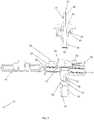
- Fig. 1shows a perspective view of the closure 12 and the dispensing fitment 14 of the closure assembly 10.
- the closure 12has a closure body 16 and a closure cap 18, which may be connected by a living hinge 20 that allows the cap 18 to be moved from an open position to a closed position or may be two separate components capable of being snap fit or otherwise connected.
- the manufacturersecures the closure body to a container by way of an inwardly threaded skirt 22 that extends downwardly from the closure deck 24 that engages an outwardly threaded neck portion of the container, and then the manufacturer closes the closure cap 18 against the closure body 16 to seal the container.
- the closure bodyalso has an upper deck 26, and a tubular hub 28 that extends downwardly from the upper deck 26 for receiving the dispensing fitment 14 when the closure cap 18 is in an open position, as shown in Fig. 1 .
- the tubular hub 28has a bottom wall 30 and an entrance orifice 32 defined within the bottom wall for receiving the dispensing fitment (see Fig. 4 ).
- a sleeve wall 34Extending downwardly from the bottom wall 30 is a sleeve wall 34 for receiving a dispensing tube (not shown), which runs to the bottom of the container.
- the dispensing tubeprovides a path through which liquid may be drawn from the bottom of the container to the tubular hub 28 so that it may be dispensed through the fitment body 36 and then through the trigger sprayer.
- Fig. 3shows how the sleeve wall 34, tubular hub 28, and dispensing fitment 14 provide a path for a liquid to flow from a dispensing tube received in the sleeve wall 34 and then through the dispensing fitment 14, though the path is blocked by the sealing boss 35 in Fig. 3 , as discussed below.
- the dispensing fitment 14has a fitment body 36 that can be assembled with the closure body 16 to form the closure assembly 10 shown in Fig. 1 .
- the fitment body 36has an arbor 38 that extends downwardly from the fitment body 36 that is rotatably and slidably received within the hub 28 of the closure body 16 as will be described further herein.
- a dispensing neck 48extends upwardly from the fitment body 36, and a flow conduit 50 extends longitudinally through the arbor 38, the fitment body 36 and the dispensing neck 48, as shown in the cross sectional view of Fig. 4 .
- the dispensing neck 48may be configured and arranged to receive the hose portion of a spray handle.
- the container wallsbegin to collapse inwards. This decreases the ability of the trigger sprayer to dispense liquid from the container, and it may cease the operation of the trigger sprayer entirely.
- the instant inventionaddresses this problem by including a sealable vent hole 52 defined on a recessed fitment seat 54 surrounding the hub 28, and radially spaced from the hub 28.
- the dispensing fitment 14enables the consumer to selectively plug and open the vent hole 52 by rotating the fitment body 36 relative to the hub 28 of the closure body 16 to cause the fitment body 36 to move linearly within the hub 28.
- annular outwardly threaded fitment neck 80extends upwardly from the upper deck 26 of the closure body 16 and surrounds the hub 28.
- An annular fitment seat 54surrounds the threaded fitment neck 80.
- annular inwardly threaded sealing wall 82extends downwardly from the fitment body. This inwardly threaded sealing wall 82 is threadably received with the outwardly threaded fitment neck 80 of the closure, and the arbor 38 is slidably and rotatably received in interfitting mating relation within the hub 28 of the closure body 16 so that the sealing wall 82 can be positioned in facing engagement with the recessed seat 54.
- the consumermay rotate the dispensing fitment 14 between an open venting position in which the sealing wall 82 is linearly displaced upwardly and not engaged with the recessed seat 54 and a closed position in which the sealing wall 80 engages the recessed seat 54 and blocks air flow through the vent hole 52.
- Figs. 1 and 3show the fitment body 36 in the closed position so that the sealing wall 82 seals the recessed seat 54 to prevent air flow through the vent hole 52.
- the dispensing fitmentmay include a radially extending actuator arm 60.
- the lower surface 62 of the actuator arm 60may include a locating tab 64 that extends downwardly from the actuator arm 60 and is capable of engaging a stop 66A corresponding to an open position and a stop 66B corresponding to the closed position.
- stops 66A, 66Bare circumferentially spaced on the closure deck 24 such that when a user rotates the actuator arm 60 until the locating tab 64 contacts the stop 66B corresponding the closed position, the lower peripheral edge 84 of the fitment sealing wall 82 is in engagement with the recessed fitment seat 54 to block the vent hole 52.
- the closure assembly 10may further include a sealing boss 35 within the flow conduit.
- the sealing boss 35is connected to the hub 28 by a plurality of connecting ribs 76.
- the sealing boss 35engages a lower end 78 of the arbor 28 when the dispensing fitment 14 is in the closed position, to prevent fluid from passing through the flow conduit 50.
- the bottom end of the arbor 38is lifted out of engagement with the boss 35 to open the flow conduit.
- the instant closure assemblyincludes a vented closure and a dispensing fitment that form a vented closure assembly with a rotatable vented plug for a container (not shown).
- the dispensing fitmentis rotatable but not threaded.
- the closure assembly 110 of the present inventionincludes a closure 112 and a dispensing fitment 114 that cooperate to provide a rotatable vented plug, which is particularly useful for spray bottles for home and garden products.
- the closure 112 and dispensing fitment 114are provided separately to the consumer, with the closure removably secured to a spray bottle or other container.
- the consumermay insert the dispensing fitment 114 into the closure 112, as described below, and then connect the hose portion of a spray handle to the dispensing fitment in order to dispense a product from the container.
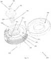
- Fig. 6shows a perspective view of the closure 112 and the dispensing fitment 114 of the closure assembly 110.
- the closure 112has a closure body 116 and a closure cap 118, which may be connected by a living hinge 120 that allows the cap to be moved from an open position to a closed position or may be two separate components capable of being snap fit or otherwise connected.
- the manufacturersecures the closure body 116 to a container by way of an inwardly threaded skirt 122 that extends downwardly from the closure deck 124 that engages an outwardly threaded neck portion of the container, and then the manufacturer closes the closure cap against the closure body to seal the container.
- the closure body 116also has an upper deck 126, and a tubular hub 128 that extends downwardly from the upper deck 126 for receiving the dispensing fitment when the closure cap 118 is in an open position, as shown in Figs. 6 and 7 .
- the tubular hub 128has a bottom wall 130 and an entrance orifice 132 defined within the bottom wall 130.
- a sleeve wall 134Extending downwardly from the bottom wall 130 is a sleeve wall 134 for receiving a dispensing tube (not shown), which runs to the bottom of the container.
- the dispensing tubeprovides a path through which liquid may be drawn from the bottom of the container to the tubular hub 128 so that it may be dispensed through the dispensing fitment 114 and then through the trigger sprayer.
- Fig. 8shows how the sleeve wall 134, tubular hub 128, and dispensing fitment 114 provide a path for a liquid to flow from a dispensing tube received in the sleeve wall 134 and then through the dispensing fitment 114.
- the dispensing fitment 114has a fitment body 136 that can be inserted into the closure body 116 to form the closure assembly 110 shown in Fig. 7 .
- the fitment body 136has an arbor 138 that extends downwardly from the fitment body 136 and can be inserted into the hub 128 of the closure body 116.
- the arbor 138includes an annular locking ledge 140 on an outside surface thereof which engages with a complementary annular groove 144 formed on an inner surface 146 of the hub.
- the locking ledge 140snaps into place within the annular groove 144, and the ledge 140 and groove 144 together maintain the dispensing fitment 114 in assembled relation with the closure body 116.
- the locking ledge 140 and groove 144are configured to allow the arbor 138 of the fitment 114 to be slidably and rotatably received in the hub 128 of the closure body.
- a dispensing neck 148extends upwardly from the fitment body 136, and a flow conduit 150 extends longitudinally through the arbor 138, the fitment body 136 and the dispensing neck 148, as shown in the cross sectional views of Fig. 8 and 9 .
- the dispensing neck 148may be configured and arranged to receive the hose portion of a spray handle (not shown).
- the container wallsbegin to collapse inwards. This decreases the ability of the trigger sprayer to dispense liquid from the container, and it may cease the operation of the trigger sprayer entirely.
- the instant inventionaddresses this problem by including a sealable vent hole 152 defined on a recessed fitment seat 154 surrounding the hub 128, and radially spaced from the hub 128.
- the dispensing fitment 114enables the consumer to selectively plug and open the vent hole 152 by rotating the fitment body 136 within the hub 128 of the closure body.
- a cantilevered arm 156extends radially outwardly from the arbor 138 of the fitment body 136, and a vent plug 158 extends downwardly from the cantilevered arm 156 so that the vent plug can be radially aligned with the vent hole.
- the arbor 138is slidably and rotatably received in interfitting mating relation within the hub 128 of the closure body 116 so that the cantilevered arm is positioned in facing engagement with the recessed seat.
- the consumermay rotate the dispensing fitment 114 between an open venting position in which the vent plug 158 is circumferentially displaced and not engaged with the vent hole 152 and a closed position in which the vent plug 158 is circumferentially aligned and engaged with the vent hole 152.
- the cantilever arm 156is flexible to provide a spring bias for firm engagement of the vent plug 158 with the vent hole 152.
- Fig. 10shows the locations of the vent hole 152 and the open and closed positions on the closure body 116.
- Figs. 6 and 8show the fitment body 136 rotated to the closed position so that the vent plug 158 seals the upper end of the vent hole 152.
- the dispensing fitment 114may include a radially extending actuator arm 160.
- the lower surface 162 of the actuator armmay include a locating tab 164 that extends downwardly from the actuator arm 160 and engages a stop 166A corresponding to an open position and a stop 166B corresponding to the closed position.
- These stops 166A, 166Bare positioned such that when a user rotates the actuator arm 160 until the locating tab 164 contacts the stop 166B corresponding the closed position, the vent plug 158 engages and seals the vent hole 152.
- the instant closure assemblyincludes a vented closure and a dispensing fitment that form a vented closure assembly with a linearly displaceable vent sealing platform (push-pull) for a container (not shown).
- the closure assembly 210 of the present inventionincludes a closure 212 and a dispensing fitment 214 with a linearly displaceable vent sealing platform 215, which is particularly useful for spray bottles for home and garden products.
- the closure 212 and dispensing fitment 214are provided separately to the consumer, with the closure 212 removably secured to a spray bottle or other container.
- the consumermay insert the dispensing fitment 214 into the closure 212, as described below, and then connect the hose portion of a spray handle (not shown) to the dispensing fitment 214 in order to dispense a product from the container.
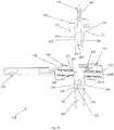
- Fig. 10shows a perspective view of the closure 212 and the dispensing fitment 214 of the closure assembly 210 when fully assembled.
- the closure 212has a closure body 216 and a closure cap 218, which may be connected by a living hinge 220 that allows the cap 218 to be moved from an open position to a closed position or may be two separate components capable of being snap fit or otherwise connected.
- the manufacturersecures the closure body 212 to a container by way of an inwardly threaded skirt 222 that extends downwardly from the closure deck 224 that engages an outwardly threaded neck portion of the container, and then the manufacturer closes the closure cap against the closure body to seal the container.
- the closure body 216also has an upper deck 226, and a tubular hub 228 that extends downwardly from the upper deck for receiving the dispensing fitment 214 when the closure cap is in an open position, as shown in Fig. 12 .
- the tubular hub 228has a bottom wall 230 and an entrance orifice 232 defined within the bottom 230 wall (see Figs. 13 and 14 ).
- a sleeve wall 234Extending downwardly from the bottom wall is a sleeve wall 234 for receiving a dispensing tube (not shown), which runs to the bottom of the container.
- the dispensing tubeprovides a path through which liquid may be drawn from the bottom of the container to the tubular hub 228 so that it may be dispensed through the fitment 214 and then through the trigger sprayer.
- Fig. 13shows how the sleeve wall 234, tubular hub 228, and dispensing fitment 214 provide a path for a liquid to flow from a dispensing tube received in the sleeve wall 234 and then through the dispensing fitment 214, though this path in Fig. 13 is blocked by the sealing boss 235, which is discussed in more detail below.
- the dispensing fitment 214has a fitment body 236 that can be inserted into the closure body 216 to form the closure assembly 210 shown in Fig. 10 .
- the fitment body 214has an arbor 238 that extends downwardly from the fitment body 236 and can be inserted into the hub 228 of the closure body 216.
- the arborincludes an annular locking ledge 240 on an outside surface 242 thereof which engages with a complementary annular groove 244 formed on an inner surface 246 of the hub.
- the locking ledge 240snaps into place within the annular groove 244, and the ledge 240 and groove 244 together maintain the dispensing fitment 214 in assembled relation with the closure body 216.
- the locking ledge 240 and groove 244are configured to allow the arbor 238 of the fitment body 236 to be slidably received in the hub 228 of the closure body 216 and linearly displaceable within the closure body 216, as discussed in more detail below.
- a dispensing neck 248extends upwardly from the fitment body 236, and a flow conduit 250 extends longitudinally through the arbor 238, the fitment body 236 and the dispensing neck 248, as shown in the cross sectional view of Fig. 13 .
- the dispensing neck 248may be configured and arranged to receive the hose portion of a spray handle.
- the container wallsbegin to collapse inwards. This decreases the ability of the trigger sprayer to dispense liquid from the container, and it may cease the operation of the trigger sprayer entirely.
- the instant inventionaddresses this problem by including a sealable vent hole 252 defined on a recessed fitment seat 254 surrounding the hub 228, and radially spaced from the hub 228.
- the dispensing fitment 214enables the consumer to selectively plug and open the vent hole 252 by linearly moving the fitment body 236 within the hub 228 of the closure body 216.
- An annular sealing platform 270extends radially outwardly from the fitment body and the annular sealing platform 270 has a lower sealing surface 272 for engaging and sealing the vent hole 252.
- the arbor 238is slidably received in interfitting mating relation within the hub 228 of the closure body 216 so that the lower sealing surface 272 of the sealing platform 270 Is positioned in facing engagement with the recessed seat 254.
- the consumermay move the dispensing fitment 214 between an open venting position in which the lower sealing surface 272 is linearly displaced upwardly and not engaged with the vent hole 252 and a closed position in which the lower sealing surface 272 engages the fitment seat 254 and blocks the vent hole 252 so that fluid may not pass through the vent hole.
- Fig. 15shows the location of the vent hole 252 on the closure body 216.
- Figs. 10 and 13show the fitment body 236 in the closed position so that the lower sealing surface 272 seals the upper end of the vent hole 252.
- the annular locking ledge 240 on the outside of the arbor 238engages an annular groove 244 on the inner surface of the hub.
- the annular groove 244has a lower edge wall 245A corresponding to the lower closed position, and an upper edge wall 245B corresponding to an open venting position.
- the locking ledge 240 and the groove 244cooperate to maintain the dispensing fitment 214 in assembled relation with the closure body 216 and provide positive locating positions of the dispensing fitment 214 relative to the closure 212.
- Fig. 13shows the fitment body 236 in the closed position, with the annular locking ledge 240 in contact with the lower edge 245A of the annular groove.
- the recessed fitment seat 254may include an upstanding annular sealing wall 273 to secure the annular sealing platform in the closed position.
- the upstanding annular sealing wall 273matingly engages with a peripheral edge 274 of the annular sealing platform 270 when the sealing platform 270 is in the closed position to create a better seal of the vent hole 252.
- the outer diameter of the peripheral edge 274can be designed to be greater than the inner diameter of the upstanding annular sealing wall 273, forming a more secure press fit between peripheral edge 274 of the sealing platform 270 and sealing wall 273.
- the hub 228may further include a sealing boss 235 within the flow conduit 250, as shown in Figs. 13 and 14 .
- the sealing boss 235is connected to the hub 228 by a plurality of radial connecting ribs 278.
- the sealing bossis positioned within the flow conduit so that it engages a lower end of the arbor when the dispensing fitment is in the closed position, as shown in Fig. 13 . In this position, the sealing boss and lower end 276 of the arbor 238 cooperate to block flow through the flow conduit 250.
- the instant inventionis believed to represent a significant advancement in the art which has substantial commercial merit.
Landscapes
- Engineering & Computer Science (AREA)
- Mechanical Engineering (AREA)
- Closures For Containers (AREA)
- Nozzles (AREA)
- Containers And Packaging Bodies Having A Special Means To Remove Contents (AREA)
Description
- The instant invention relates to closures for spray bottles, and more particularly to vented closure assemblies having a vent that opens to facilitate spraying.
- In
US 2010/108724 to Buchalter , there is shown a twist open / twist close closure for a container wherein the finger of the hand that holds the container can open or close the twist open / twist close closure. - According to an aspect of the invention there is provided: a closure assembly for a container of a spray system, the closure assembly comprising:
- a closure; and
- a dispensing fitment,
- said closure including
- a closure body, and
- a closure cap,
- said closure body having an upper deck, a tubular hub extending downwardly from said upper deck, an annular outwardly threaded fitment neck extending upwardly from said upper deck and surrounding said tubular hub, an annular recessed fitment seat surrounding said annular outwardly threaded fitment neck, and a skirt extending downwardly from a closure deck,
- said hub having a bottom wall and an entrance orifice within said bottom wall, said hub further including a sleeve wall extending downwardly from said bottom wall for receiving therein a dispensing tube, said recessed fitment seat having a vent hole radially spaced from said hub, said skirt being configured and arranged for engaging a neck of a container,
- said dispensing fitment including
- a fitment body,
- an arbor extending downwardly from said fitment body,
- an annular inwardly threaded sealing wall extending downwardly from said fitment body,
- a dispensing neck extending upwardly from said fitment body, and
- a flow conduit extending longitudinally through said arbor, said fitment body and said dispensing neck,
- said annular inwardly threaded sealing wall being threadably received with said annular outwardly threaded fitment neck of said closure while said arbor is slidably and rotatably received in interfitting mating relation within said hub of said closure body,
- said dispensing fitment being rotatably and linearly movable relative to said closure between a lower closed position where a lower peripheral edge of said annular inwardly threaded sealing wall is in engagement with said annular recessed fitment seat to block said vent hole and an upper open position where said lower peripheral edge of said annular inwardly threaded sealing wall is spaced upwardly from said vent hole allowing air to pass through said vent hole.
- Optionally, the dispensing fitment includes a radially extending actuator arm. The dispensing fitment may include a locating tab, and said closure deck may include circumferentially spaced locating stops corresponding to said open and closed positions.
- The hub may further include a sealing boss within said flow conduit, said sealing boss being connected to said hub by a plurality of connecting ribs and said sealing boss may engage a lower end of said arbor when said dispensing fitment is in said closed position.
- Optionally, a living hinge connects said closure cap to said closure body whereby said closure cap is movable between an open and a closed position
- An exemplary embodiment describes a vented closure assembly for a container of a spray system where the closure assembly includes a closure and a separate dispensing fitment which are threaded to create a rotatable linear translation of the fitment.
- The closure includes a closure body, a closure cap, and a living hinge connecting the closure cap to the closure body. During shipment, sale and storage the dispensing fitment is removed and the closure cap closed to fully seal the closure and container. In use, the operator opens the cap and assembles the dispensing fitment with the closure.
- The closure body has an upper deck, a tubular hub extending downwardly from the upper deck, an annular outwardly threaded fitment neck extending upwardly from the upper deck and surrounding the hub, an annular recessed fitment seat surrounding the fitment neck, and a skirt extending downwardly from the closure deck for engagement with the container. The hub has a bottom wall and an entrance orifice within the bottom wall. The hub further includes a sleeve wall extending downwardly from the bottom wall for receiving therein a sprayer dispensing tube which extends from the bottom of the hub downwardly to the bottom of the container. In accordance with the invention, the recessed fitment seat has a vent hole radially spaced from the hub.
- The dispensing fitment includes a fitment body, an arbor extending downwardly from the fitment body, an annular inwardly threaded sealing wall extending downwardly from the fitment body, a dispensing neck extending upwardly from the fitment body, and a flow conduit extending longitudinally through the arbor, the fitment body and the dispensing neck.
- To assemble the components, the inwardly threaded sealing wall is threadably received with the outwardly threaded fitment neck of the closure while the arbor of the fitment is slidably and rotatably received in interfitting mated engagement within the hub. The dispensing fitment is thereafter rotatably and linearly movable relative to the closure body between a lower closed position in which a lower peripheral edge of the fitment sealing wall is in engagement with the recessed fitment seat to block the vent hole, and an upper open position in which the lower peripheral edge of the fitment sealing wall is spaced upwardly from the vent hole allowing air to pass through the vent hole.
- The dispensing fitment preferably includes a radially extending actuator arm which is selectively manipulated by the user to rotate the fitment between the open and closed positions.
- In order to facilitate proper rotational positioning of the fitment, the dispensing fitment includes a locating tab which engages with circumferentially spaced locating stops on the upper deck corresponding to the open and closed positions. In the preferred embodiment, the locating tab is formed on the bottom of the actuator arm.
- A second exemplary embodiment includes a closure and a dispensing fitment which is rotatable (but not threaded).
- The closure includes a closure body, a closure cap, and a living hinge connecting the closure cap to the closure body. During shipment, sale and storage the dispensing fitment is removed and the closure cap closed to fully seal the closure and container. In use, the operator opens the cap and assembles the dispensing fitment with the closure.
- The closure body has an upper deck, a tubular hub extending downwardly from the upper deck, a recessed fitment seat surrounding the hub, and an outer skirt extending downwardly from the closure deck for engagement with the container. The hub has a bottom wall and an entrance orifice within the bottom wall. The hub further includes a sleeve wall extending downwardly from the bottom wall for receiving therein a sprayer dispensing tube which extends from the bottom of the hub downwardly to the bottom of the container. In accordance with the invention, the recessed seat has a vent hole radially spaced from the hub.
- The dispensing fitment includes a fitment body, an arbor extending downwardly from the fitment body, a cantilevered arm extending radially outwardly from the arbor, a vent plug extending downwardly from a distal end of the cantilevered arm, a dispensing neck extending upwardly from the fitment body, and a flow conduit extending longitudinally through the arbor, the fitment body and the dispensing neck.
- To assemble the components, the arbor of the fitment is slidably received in interfitting mated engagement within the hub such that cantilever arm rests on the upper surface of the recessed fitment seat. The dispensing fitment is thereafter rotatably movable relative to the closure body between an open venting position where the vent plug on the end of the cantilever arm is circumferentially displaced from, and not engaged with, the vent hole, and a closed position where the vent plug is circumferentially aligned with, and engaged with the vent hole. The cantilever arm is flexible to provide a spring bias for firm engagement of the vent plug with the vent hole. To maintain the dispensing fitment in assembled relation with the closure body, the arbor includes an annular locking ledge on an outside surface thereof which engages with a complementary annular groove formed on an inner surface of the hub. When assembled the annular ledge is snap received within the groove to prevent relative linear movement of the parts, but still allows for rotation of the arbor relative to the inner wall of the hub.
- The dispensing fitment preferably includes a radially extending actuator arm which is selectively manipulated by the user to rotate the fitment between the open and closed positions.
- In order to facilitate proper rotational positioning of the fitment, the dispensing fitment includes a locating tab which engages with circumferentially spaced locating stops on the upper deck corresponding to the open and closed positions. In the preferred embodiment, the locating tab is formed on the bottom of the actuator arm.
- A third exemplary embodiment includes a closure and a dispensing fitment which is linearly movable (push-pull) (but not threaded).
- The closure includes a closure body, a closure cap, and a living hinge connecting the closure cap to the closure body. During shipment, sale and storage the dispensing fitment is removed and the closure cap closed to fully seal the closure and container. In use, the operator opens the cap and assembles the dispensing fitment with the closure.
- The closure body has an upper deck, a tubular hub extending downwardly from the upper deck, a recessed fitment seat surrounding the hub, and an outer skirt extending downwardly from the closure deck for engagement with the container. The hub has a bottom wall and an entrance orifice within the bottom wall. The hub further includes a sleeve wall extending downwardly from the bottom wall for receiving therein a sprayer dispensing tube which extends from the bottom of the hub downwardly to the bottom of the container. In accordance with the invention, the recessed seat has a vent hole radially spaced from the hub.
- The dispensing fitment includes a fitment body having an annular sealing platform extending radially outwardly from the fitment body, a lower sealing surface formed on the sealing platform, an arbor extending downwardly from the fitment body, a dispensing neck extending upwardly from the fitment body, and a flow conduit extending longitudinally through the arbor, the fitment body and the dispensing neck.
- To assemble the components, the arbor of the fitment is slidably received in interfitting mated engagement within the hub such that the lower surface of the annular sealing platform is positioned in facing engagement with the recessed seat. The dispensing fitment is linearly movable relative to the closure between a lower closed position in which the lower surface of the annular sealing platform engages the recessed fitment seat and blocks the vent hole, and an open venting position in which the lower surface of the annular sealing platform is spaced upwardly from the recessed fitment seat and allows air to pass through the vent hole.
- To maintain the dispensing fitment in assembled relation with the closure body, the arbor includes an annular locking ledge on an outside surface thereof which engages with a complementary annular groove formed on an inner surface of the hub.
- When assembled the annular locking ledge is snap received within the groove to limit relative linear movement of the parts, but still allows for linear displacement of the arbor relative to the inner wall of the hub between the open venting position and the lower closed position. In order to facilitate proper linear positioning of the fitment, the annular locking ledge is linearly displaceable within the annular groove formed on an inner surface of the hub. The annular groove has a lower edge wall corresponding to the lower closed position and an upper edge wall corresponding to the open venting position. The locking ledge and the groove cooperate to maintain the dispensing fitment in assembled relation with the closure body and provide positive locating positions of the dispensing fitment relative to the closure.
- While the specification concludes with claims particularly pointing out and distinctly claiming particular embodiments of the instant invention, various embodiments of the invention can be more readily understood and appreciated from the following descriptions of various embodiments of the invention when read in conjunction with the accompanying drawings in which:
Fig. 1 is a perspective view of one exemplary embodiment of a closure assembly of the present invention;Fig. 2 is an exploded view thereof;Fig. 3 is a cross-sectional view of the closure assembly ofFig. 1 ;Fig. 4 is an exploded view thereof;Fig. 5 is a top view of the closure with the dispensing fitment removed;Fig. 6 is a perspective view of another exemplary embodiment of the closure assembly of the present invention;Fig. 7 is an exploded view thereof;Fig. 8 is a cross-sectional view of the closure assembly showing the vent plug engaging the vent hole;Fig. 9 is an exploded cross-sectional view of the closure assembly;Fig. 10 is a top view of the closure with the dispensing fitment removed;Fig. 11 is a perspective view of still another exemplary closure assembly of the present invention;Fig. 12 is an exploded view thereof;Fig. 13 is a cross-sectional view of the closure assembly showing the recessed fitment seat blocking the vent hole;Fig. 14 is an exploded cross-sectional view of the closure assembly; andFig. 15 Is a top view of the closure with the dispensing fitment removed.- Referring now to the drawings, an exemplary embodiment of the closure assembly is illustrated and generally indicated at 10 in
Figs. 1-5 . As will hereinafter be more fully described, the instant closure assembly includes a vented closure and a dispensing fitment that form a vented closure assembly with a rotatable and linearly movable vented plug for a container (not shown). - The
closure assembly 10 of the present invention includes aclosure 12 and a dispensingfitment 14 that cooperate to provide a rotatable venting arrangement, which is particularly useful for spray bottles for home and garden products. Theclosure 12 and dispensingfitment 14 are provided separately to the consumer, with theclosure 12 removably secured to a spray bottle or other container. When ready to use the product, the consumer may assemble the dispensingfitment 14 with the closure, as described below, and then connect the hose portion of a spray handle (not shown) to the dispensingfitment 14 in order to dispense a product from the container. Fig. 1 shows a perspective view of theclosure 12 and the dispensingfitment 14 of theclosure assembly 10. Theclosure 12 has aclosure body 16 and aclosure cap 18, which may be connected by a livinghinge 20 that allows thecap 18 to be moved from an open position to a closed position or may be two separate components capable of being snap fit or otherwise connected. The manufacturer secures the closure body to a container by way of an inwardly threadedskirt 22 that extends downwardly from theclosure deck 24 that engages an outwardly threaded neck portion of the container, and then the manufacturer closes theclosure cap 18 against theclosure body 16 to seal the container.- The closure body also has an
upper deck 26, and atubular hub 28 that extends downwardly from theupper deck 26 for receiving the dispensingfitment 14 when theclosure cap 18 is in an open position, as shown inFig. 1 . Thetubular hub 28 has abottom wall 30 and anentrance orifice 32 defined within the bottom wall for receiving the dispensing fitment (seeFig. 4 ). - Extending downwardly from the
bottom wall 30 is asleeve wall 34 for receiving a dispensing tube (not shown), which runs to the bottom of the container. The dispensing tube provides a path through which liquid may be drawn from the bottom of the container to thetubular hub 28 so that it may be dispensed through thefitment body 36 and then through the trigger sprayer.Fig. 3 shows how thesleeve wall 34,tubular hub 28, and dispensingfitment 14 provide a path for a liquid to flow from a dispensing tube received in thesleeve wall 34 and then through the dispensingfitment 14, though the path is blocked by the sealingboss 35 inFig. 3 , as discussed below. - The dispensing
fitment 14 has afitment body 36 that can be assembled with theclosure body 16 to form theclosure assembly 10 shown inFig. 1 . Thefitment body 36 has anarbor 38 that extends downwardly from thefitment body 36 that is rotatably and slidably received within thehub 28 of theclosure body 16 as will be described further herein. - To allow the product to be dispensed from the container, a dispensing
neck 48 extends upwardly from thefitment body 36, and aflow conduit 50 extends longitudinally through thearbor 38, thefitment body 36 and the dispensingneck 48, as shown in the cross sectional view ofFig. 4 . The dispensingneck 48 may be configured and arranged to receive the hose portion of a spray handle. - When a liquid volume is dispensed from a container using a trigger sprayer and air is not allowed to enter the container, the container walls begin to collapse inwards. This decreases the ability of the trigger sprayer to dispense liquid from the container, and it may cease the operation of the trigger sprayer entirely. The instant invention addresses this problem by including a
sealable vent hole 52 defined on a recessedfitment seat 54 surrounding thehub 28, and radially spaced from thehub 28. - However, when using a container in a trigger spray system, it is also desirable for the user to be able to prevent bottle leakage when the liquid container is not in use. The instant invention allows the user to seal the
vent hole 52 as needed to prevent inadvertent bottle leakage. As described below, the dispensingfitment 14 enables the consumer to selectively plug and open thevent hole 52 by rotating thefitment body 36 relative to thehub 28 of theclosure body 16 to cause thefitment body 36 to move linearly within thehub 28. - An annular outwardly threaded
fitment neck 80 extends upwardly from theupper deck 26 of theclosure body 16 and surrounds thehub 28. Anannular fitment seat 54 surrounds the threadedfitment neck 80. On thefitment body 36, an annular inwardly threaded sealingwall 82 extends downwardly from the fitment body. This inwardly threaded sealingwall 82 is threadably received with the outwardly threadedfitment neck 80 of the closure, and thearbor 38 is slidably and rotatably received in interfitting mating relation within thehub 28 of theclosure body 16 so that the sealingwall 82 can be positioned in facing engagement with the recessedseat 54. Thus, the consumer may rotate the dispensingfitment 14 between an open venting position in which the sealingwall 82 is linearly displaced upwardly and not engaged with the recessedseat 54 and a closed position in which the sealingwall 80 engages the recessedseat 54 and blocks air flow through thevent hole 52.Figs. 1 and3 show thefitment body 36 in the closed position so that the sealingwall 82 seals the recessedseat 54 to prevent air flow through thevent hole 52. - In order to facilitate rotation of the dispensing
fitment 14 within thehub 28 of theclosure body 16, the dispensing fitment may include a radially extendingactuator arm 60. To further facilitate rotation of the dispensingfitment 14 between the closed position and the open position, thelower surface 62 of theactuator arm 60 may include a locatingtab 64 that extends downwardly from theactuator arm 60 and is capable of engaging astop 66A corresponding to an open position and astop 66B corresponding to the closed position. These stops 66A, 66B are circumferentially spaced on theclosure deck 24 such that when a user rotates theactuator arm 60 until the locatingtab 64 contacts thestop 66B corresponding the closed position, the lowerperipheral edge 84 of thefitment sealing wall 82 is in engagement with the recessedfitment seat 54 to block thevent hole 52. - The
closure assembly 10 may further include a sealingboss 35 within the flow conduit. The sealingboss 35 is connected to thehub 28 by a plurality of connectingribs 76. The sealingboss 35 engages alower end 78 of thearbor 28 when the dispensingfitment 14 is in the closed position, to prevent fluid from passing through theflow conduit 50. As thefitment 14 is rotated the bottom end of thearbor 38 is lifted out of engagement with theboss 35 to open the flow conduit. - Another exemplary embodiment of the closure assembly of the instant invention is illustrated and generally indicated at 110 in
Figs. 6-10 . As will hereinafter be more fully described, the instant closure assembly includes a vented closure and a dispensing fitment that form a vented closure assembly with a rotatable vented plug for a container (not shown). The dispensing fitment is rotatable but not threaded. - The
closure assembly 110 of the present invention includes aclosure 112 and a dispensingfitment 114 that cooperate to provide a rotatable vented plug, which is particularly useful for spray bottles for home and garden products. Theclosure 112 and dispensingfitment 114 are provided separately to the consumer, with the closure removably secured to a spray bottle or other container. When ready to use the product, the consumer may insert the dispensingfitment 114 into theclosure 112, as described below, and then connect the hose portion of a spray handle to the dispensing fitment in order to dispense a product from the container. Fig. 6 shows a perspective view of theclosure 112 and the dispensingfitment 114 of theclosure assembly 110. Theclosure 112 has aclosure body 116 and aclosure cap 118, which may be connected by aliving hinge 120 that allows the cap to be moved from an open position to a closed position or may be two separate components capable of being snap fit or otherwise connected. The manufacturer secures theclosure body 116 to a container by way of an inwardly threadedskirt 122 that extends downwardly from theclosure deck 124 that engages an outwardly threaded neck portion of the container, and then the manufacturer closes the closure cap against the closure body to seal the container.- The
closure body 116 also has anupper deck 126, and atubular hub 128 that extends downwardly from theupper deck 126 for receiving the dispensing fitment when theclosure cap 118 is in an open position, as shown inFigs. 6 and7 . Thetubular hub 128 has abottom wall 130 and anentrance orifice 132 defined within thebottom wall 130. - Extending downwardly from the
bottom wall 130 is asleeve wall 134 for receiving a dispensing tube (not shown), which runs to the bottom of the container. The dispensing tube provides a path through which liquid may be drawn from the bottom of the container to thetubular hub 128 so that it may be dispensed through the dispensingfitment 114 and then through the trigger sprayer.Fig. 8 shows how thesleeve wall 134,tubular hub 128, and dispensingfitment 114 provide a path for a liquid to flow from a dispensing tube received in thesleeve wall 134 and then through the dispensingfitment 114. - The dispensing
fitment 114 has afitment body 136 that can be inserted into theclosure body 116 to form theclosure assembly 110 shown inFig. 7 . Thefitment body 136 has anarbor 138 that extends downwardly from thefitment body 136 and can be inserted into thehub 128 of theclosure body 116. To secure the dispensingfitment 114 within thehub 128 of theclosure body 116, thearbor 138 includes anannular locking ledge 140 on an outside surface thereof which engages with a complementaryannular groove 144 formed on aninner surface 146 of the hub. When the consumer inserts the dispensingfitment 114 into theclosure body 116, the lockingledge 140 snaps into place within theannular groove 144, and theledge 140 and groove 144 together maintain the dispensingfitment 114 in assembled relation with theclosure body 116. The lockingledge 140 and groove 144 are configured to allow thearbor 138 of thefitment 114 to be slidably and rotatably received in thehub 128 of the closure body. - To allow the product to be dispensed from the container, a dispensing
neck 148 extends upwardly from thefitment body 136, and aflow conduit 150 extends longitudinally through thearbor 138, thefitment body 136 and the dispensingneck 148, as shown in the cross sectional views ofFig. 8 and9 . The dispensingneck 148 may be configured and arranged to receive the hose portion of a spray handle (not shown). - When a liquid volume is dispensed from a container using a trigger sprayer and air is not allowed to enter the container, the container walls begin to collapse inwards. This decreases the ability of the trigger sprayer to dispense liquid from the container, and it may cease the operation of the trigger sprayer entirely. The instant invention addresses this problem by including a
sealable vent hole 152 defined on a recessedfitment seat 154 surrounding thehub 128, and radially spaced from thehub 128. - However, when using a container in a trigger spray system, it is also desirable for the user to be able to prevent bottle leakage when the liquid container is not in use. The instant invention allows the user to seal the
vent hole 152 as needed to prevent inadvertent bottle leakage. As described below, the dispensingfitment 114 enables the consumer to selectively plug and open thevent hole 152 by rotating thefitment body 136 within thehub 128 of the closure body. - A
cantilevered arm 156 extends radially outwardly from thearbor 138 of thefitment body 136, and avent plug 158 extends downwardly from the cantileveredarm 156 so that the vent plug can be radially aligned with the vent hole. Thearbor 138 is slidably and rotatably received in interfitting mating relation within thehub 128 of theclosure body 116 so that the cantilevered arm is positioned in facing engagement with the recessed seat. Thus, the consumer may rotate the dispensingfitment 114 between an open venting position in which thevent plug 158 is circumferentially displaced and not engaged with thevent hole 152 and a closed position in which thevent plug 158 is circumferentially aligned and engaged with thevent hole 152. Thecantilever arm 156 is flexible to provide a spring bias for firm engagement of thevent plug 158 with thevent hole 152.Fig. 10 shows the locations of thevent hole 152 and the open and closed positions on theclosure body 116.Figs. 6 and8 show thefitment body 136 rotated to the closed position so that the vent plug 158 seals the upper end of thevent hole 152. - In order to facilitate rotation of the dispensing
fitment 114 within thehub 128 of theclosure body 116, the dispensingfitment 114 may include a radially extendingactuator arm 160. To further facilitate rotation of the dispensingfitment 114 between the closed position and the open position, thelower surface 162 of the actuator arm may include alocating tab 164 that extends downwardly from theactuator arm 160 and engages astop 166A corresponding to an open position and astop 166B corresponding to the closed position. These stops 166A, 166B are positioned such that when a user rotates theactuator arm 160 until thelocating tab 164 contacts thestop 166B corresponding the closed position, thevent plug 158 engages and seals thevent hole 152. - Another exemplary embodiment of the closure assembly of the instant invention is illustrated and generally shown at 210 in
Figs. 11-15 . As will hereinafter be more fully described, the instant closure assembly includes a vented closure and a dispensing fitment that form a vented closure assembly with a linearly displaceable vent sealing platform (push-pull) for a container (not shown). - The
closure assembly 210 of the present invention includes aclosure 212 and a dispensingfitment 214 with a linearly displaceable vent sealing platform 215, which is particularly useful for spray bottles for home and garden products. Theclosure 212 and dispensingfitment 214 are provided separately to the consumer, with theclosure 212 removably secured to a spray bottle or other container. When ready to use the product, the consumer may insert the dispensingfitment 214 into theclosure 212, as described below, and then connect the hose portion of a spray handle (not shown) to the dispensingfitment 214 in order to dispense a product from the container. Fig. 10 shows a perspective view of theclosure 212 and the dispensingfitment 214 of theclosure assembly 210 when fully assembled. Theclosure 212 has aclosure body 216 and aclosure cap 218, which may be connected by aliving hinge 220 that allows thecap 218 to be moved from an open position to a closed position or may be two separate components capable of being snap fit or otherwise connected. The manufacturer secures theclosure body 212 to a container by way of an inwardly threadedskirt 222 that extends downwardly from theclosure deck 224 that engages an outwardly threaded neck portion of the container, and then the manufacturer closes the closure cap against the closure body to seal the container.- The
closure body 216 also has anupper deck 226, and atubular hub 228 that extends downwardly from the upper deck for receiving the dispensingfitment 214 when the closure cap is in an open position, as shown inFig. 12 . Thetubular hub 228 has abottom wall 230 and anentrance orifice 232 defined within the bottom 230 wall (seeFigs. 13 and14 ). - Extending downwardly from the bottom wall is a
sleeve wall 234 for receiving a dispensing tube (not shown), which runs to the bottom of the container. The dispensing tube provides a path through which liquid may be drawn from the bottom of the container to thetubular hub 228 so that it may be dispensed through thefitment 214 and then through the trigger sprayer.Fig. 13 shows how thesleeve wall 234,tubular hub 228, and dispensingfitment 214 provide a path for a liquid to flow from a dispensing tube received in thesleeve wall 234 and then through the dispensingfitment 214, though this path inFig. 13 is blocked by the sealingboss 235, which is discussed in more detail below. - The dispensing
fitment 214 has afitment body 236 that can be inserted into theclosure body 216 to form theclosure assembly 210 shown inFig. 10 . Thefitment body 214 has anarbor 238 that extends downwardly from thefitment body 236 and can be inserted into thehub 228 of theclosure body 216. To secure the dispensingfitment 214 within thehub 228 of theclosure body 216, the arbor includes anannular locking ledge 240 on anoutside surface 242 thereof which engages with a complementaryannular groove 244 formed on aninner surface 246 of the hub. When the consumer inserts the dispensingfitment 214 into theclosure body 216, the lockingledge 240 snaps into place within theannular groove 244, and theledge 240 and groove 244 together maintain the dispensingfitment 214 in assembled relation with theclosure body 216. The lockingledge 240 and groove 244 are configured to allow thearbor 238 of thefitment body 236 to be slidably received in thehub 228 of theclosure body 216 and linearly displaceable within theclosure body 216, as discussed in more detail below. - To allow the product to be dispensed from the container, a dispensing
neck 248 extends upwardly from thefitment body 236, and aflow conduit 250 extends longitudinally through thearbor 238, thefitment body 236 and the dispensingneck 248, as shown in the cross sectional view ofFig. 13 . The dispensingneck 248 may be configured and arranged to receive the hose portion of a spray handle. - When a liquid volume is dispensed from a container using a trigger sprayer and air is not allowed to enter the container, the container walls begin to collapse inwards. This decreases the ability of the trigger sprayer to dispense liquid from the container, and it may cease the operation of the trigger sprayer entirely. The instant invention addresses this problem by including a
sealable vent hole 252 defined on a recessedfitment seat 254 surrounding thehub 228, and radially spaced from thehub 228. - However, when using a container in a trigger spray system, it is also desirable for the user to be able to prevent bottle leakage when the liquid container is not in use. The instant invention allows the user to seal the
vent hole 252 as needed to prevent inadvertent bottle leakage. As described below, the dispensingfitment 214 enables the consumer to selectively plug and open thevent hole 252 by linearly moving thefitment body 236 within thehub 228 of theclosure body 216. - An
annular sealing platform 270 extends radially outwardly from the fitment body and theannular sealing platform 270 has alower sealing surface 272 for engaging and sealing thevent hole 252. Thearbor 238 is slidably received in interfitting mating relation within thehub 228 of theclosure body 216 so that thelower sealing surface 272 of thesealing platform 270 Is positioned in facing engagement with the recessedseat 254. Thus, the consumer may move the dispensingfitment 214 between an open venting position in which thelower sealing surface 272 is linearly displaced upwardly and not engaged with thevent hole 252 and a closed position in which thelower sealing surface 272 engages thefitment seat 254 and blocks thevent hole 252 so that fluid may not pass through the vent hole.Fig. 15 shows the location of thevent hole 252 on theclosure body 216.Figs. 10 and13 show thefitment body 236 in the closed position so that thelower sealing surface 272 seals the upper end of thevent hole 252. - In order to enable a user to more easily move the fitment body between the open position and closed position, the
annular locking ledge 240 on the outside of thearbor 238 engages anannular groove 244 on the inner surface of the hub. Theannular groove 244 has alower edge wall 245A corresponding to the lower closed position, and anupper edge wall 245B corresponding to an open venting position. The lockingledge 240 and thegroove 244 cooperate to maintain the dispensingfitment 214 in assembled relation with theclosure body 216 and provide positive locating positions of the dispensingfitment 214 relative to theclosure 212.Fig. 13 shows thefitment body 236 in the closed position, with theannular locking ledge 240 in contact with thelower edge 245A of the annular groove. Moving the fitment body upwardly so that theannular locking ledge 240 is in contact with theupper edge wall 245B would unseal thevent hole 252. Thus, a user may simply operate the venting mechanism of the instant invention by pushing or pulling on thefitment body 236 with respect to theclosure body 216 to selectively form a sealed or vented closure. - The recessed
fitment seat 254 may include an upstandingannular sealing wall 273 to secure the annular sealing platform in the closed position. The upstandingannular sealing wall 273 matingly engages with aperipheral edge 274 of theannular sealing platform 270 when thesealing platform 270 is in the closed position to create a better seal of thevent hole 252. The outer diameter of theperipheral edge 274 can be designed to be greater than the inner diameter of the upstandingannular sealing wall 273, forming a more secure press fit betweenperipheral edge 274 of thesealing platform 270 and sealingwall 273. - The
hub 228 may further include a sealingboss 235 within theflow conduit 250, as shown inFigs. 13 and14 . The sealingboss 235 is connected to thehub 228 by a plurality ofradial connecting ribs 278. The sealing boss is positioned within the flow conduit so that it engages a lower end of the arbor when the dispensing fitment is in the closed position, as shown inFig. 13 . In this position, the sealing boss andlower end 276 of thearbor 238 cooperate to block flow through theflow conduit 250. - For these reasons outlined herein, the instant invention is believed to represent a significant advancement in the art which has substantial commercial merit.
- While there is shown and described herein certain specific structure embodying the invention, it will be manifest to those skilled in the art that various modifications and rearrangements of the parts may be made without departing from the spirit and scope of the underlying inventive concept and that the same is not limited to the particular forms herein shown and described except insofar as indicated by the scope of the appended claims.
Claims (5)
- A closure assembly (10) for a container of a spray system, the closure assembly comprising:a closure (12); anda dispensing fitment (14),said closure includinga closure body (16), anda closure cap (18),said closure body (16) having an upper deck (26), a tubular hub (28) extending downwardly from said upper deck, an annular outwardly threaded fitment neck (80) extending upwardly from said upper deck and surrounding said tubular hub, an annular recessed fitment seat (54) surrounding said annular outwardly threaded fitment neck (80), and a skirt extending downwardly from a closure deck (24),said hub having a bottom wall (30) and an entrance orifice (32) within said bottom wall, said hub further including a sleeve wall (34) extending downwardly from said bottom wall for receiving therein a dispensing tube, said recessed fitment seat having a vent hole (52) radially spaced from said hub, said skirt being configured and arranged for engaging a neck of a container,said dispensing fitment includinga fitment body (36),an arbor (38) extending downwardly from said fitment body,an annular inwardly threaded sealing wall (82) extending downwardly from said fitment body,a dispensing neck (48) extending upwardly from said fitment body, anda flow conduit (50) extending longitudinally through said arbor, said fitment body and said dispensing neck,said annular inwardly threaded sealing wall (82) being threadably received with said annular outwardly threaded fitment neck (80) of said closure (12) while said arbor (38) is slidably and rotatably received in interfitting mating relation within said hub of said closure body,said dispensing fitment being rotatably and linearly movable relative to said closure between a lower closed position where a lower peripheral edge (84) of said annular inwardly threaded sealing wall (82) is in engagement with said annular recessed fitment seat (54) to block said vent hole (52) and an upper open position where said lower peripheral edge (84) of said annular inwardly threaded sealing wall is spaced upwardly from said vent hole allowing air to pass through said vent hole.
- The closure assembly of claim 1 wherein said dispensing fitment includes a radially extending actuator arm (60).
- The closure assembly of claim 1 or 2 wherein said dispensing fitment includes a locating tab (64), and said closure deck (24) includes circumferentially spaced locating stops (66A, 66B) corresponding to said open and closed positions.
- The closure assembly of claim 1 wherein said hub further includes a sealing boss (35) within said flow conduit, said sealing boss being connected to said hub by a plurality of connecting ribs (76), said sealing boss engaging a lower end of said arbor when said dispensing fitment is in said closed position.
- The closure assembly of claim 1 further comprising a living hinge (20) connecting said closure cap to said closure body whereby said closure cap is movable between an open and a closed position.
Priority Applications (1)
| Application Number | Priority Date | Filing Date | Title |
|---|---|---|---|
| EP19151991.7AEP3498623B1 (en) | 2013-03-15 | 2014-03-13 | Vented closure assembly for a spray container |
Applications Claiming Priority (4)
| Application Number | Priority Date | Filing Date | Title |
|---|---|---|---|
| US201361788089P | 2013-03-15 | 2013-03-15 | |
| US201361788362P | 2013-03-15 | 2013-03-15 | |
| US201361789197P | 2013-03-15 | 2013-03-15 | |
| PCT/US2014/025209WO2014151208A2 (en) | 2013-03-15 | 2014-03-13 | Vented closure assembly for a spray container |
Related Child Applications (1)
| Application Number | Title | Priority Date | Filing Date |
|---|---|---|---|
| EP19151991.7ADivisionEP3498623B1 (en) | 2013-03-15 | 2014-03-13 | Vented closure assembly for a spray container |
Publications (3)
| Publication Number | Publication Date |
|---|---|
| EP2969804A2 EP2969804A2 (en) | 2016-01-20 |
| EP2969804A4 EP2969804A4 (en) | 2017-03-01 |
| EP2969804B1true EP2969804B1 (en) | 2019-01-16 |
Family
ID=51581636
Family Applications (2)
| Application Number | Title | Priority Date | Filing Date |
|---|---|---|---|
| EP14768188.6AActiveEP2969804B1 (en) | 2013-03-15 | 2014-03-13 | Vented closure assembly for a spray container |
| EP19151991.7AActiveEP3498623B1 (en) | 2013-03-15 | 2014-03-13 | Vented closure assembly for a spray container |
Family Applications After (1)
| Application Number | Title | Priority Date | Filing Date |
|---|---|---|---|
| EP19151991.7AActiveEP3498623B1 (en) | 2013-03-15 | 2014-03-13 | Vented closure assembly for a spray container |
Country Status (3)
| Country | Link |
|---|---|
| US (2) | US10201821B2 (en) |
| EP (2) | EP2969804B1 (en) |
| WO (1) | WO2014151208A2 (en) |
Families Citing this family (6)
| Publication number | Priority date | Publication date | Assignee | Title |
|---|---|---|---|---|
| US10676259B1 (en)* | 2018-11-15 | 2020-06-09 | Silgan Dispensing Systems Corporation | Two-part dispensing closure system with internal seal and methods of using the same |
| US11059633B2 (en) | 2019-10-31 | 2021-07-13 | Cheer Pack North America | Flip-top closure for container |
| TWI697362B (en)* | 2019-11-06 | 2020-07-01 | 邱森玉 | Spray structure of container |
| USD980069S1 (en) | 2020-07-14 | 2023-03-07 | Ball Corporation | Metallic dispensing lid |
| WO2022187190A1 (en) | 2021-03-01 | 2022-09-09 | Ball Corporation | Metal container and end closure with seal |
| US11999537B2 (en)* | 2022-01-25 | 2024-06-04 | Helen Of Troy Limited | Poppet lid |
Family Cites Families (40)
| Publication number | Priority date | Publication date | Assignee | Title |
|---|---|---|---|---|
| US3520452A (en) | 1968-11-29 | 1970-07-14 | Afa Corp | Leakproof container seal |
| US3780951A (en)* | 1973-01-30 | 1973-12-25 | Afa Corp | Leakproof head for hand sprayer |
| US4222500A (en)* | 1978-07-24 | 1980-09-16 | James D. Pauls, Limited | Non-propellant, duration spray dispenser with positive shut off valve |
| US4485943A (en)* | 1982-03-08 | 1984-12-04 | Joachim Czech | Dispenser for liquids or pasty products |
| EP0722783B1 (en)* | 1989-12-28 | 2000-02-23 | Yoshino Kogyosho Co., Ltd. | Liquid jet blower |
| US5183185A (en)* | 1991-02-14 | 1993-02-02 | Ecopac, L. P. | Mechanically pressurized dispenser system |
| US5318206A (en)* | 1992-02-24 | 1994-06-07 | Afa Products, Inc. | Trigger-piston connection |
| FR2711554B1 (en)* | 1993-10-22 | 1995-12-22 | Oreal | Distribution unit with controlled air intake. |
| US5664703A (en)* | 1994-02-28 | 1997-09-09 | The Procter & Gamble Company | Pump device with collapsible pump chamber having supply container venting system and integral shipping seal |
| US5605257A (en)* | 1996-03-04 | 1997-02-25 | Beard; Walter C. | Sterile liquid squeeze-bottle-type dispenser |
| US6192797B1 (en)* | 1999-12-23 | 2001-02-27 | Sonoco Development, Inc. | Ink cartridge for automated dispensing systems |
| US6708852B2 (en)* | 2001-08-20 | 2004-03-23 | Alternative Packaging Solutions, L.P. | Non-chemical aerosol dispenser |
| US6547108B2 (en)* | 2001-08-31 | 2003-04-15 | Sonoco Development, Inc. | Pressure-activated flexible valve |
| US7913877B2 (en)* | 2003-01-21 | 2011-03-29 | Aptargroup Inc. | Aerosol mounting cup for connection to a collapsible container |
| US7686194B2 (en)* | 2003-09-03 | 2010-03-30 | Rieke Corporation | Closed loop fluid dispensing system |
| US7322493B2 (en) | 2003-10-09 | 2008-01-29 | Polytop Corporation | Dispensing closure having complete peripheral seal |
| CN1308188C (en)* | 2004-10-08 | 2007-04-04 | 蒋一新 | Liquid packaging bottle twist cap |
| WO2007127982A2 (en)* | 2006-04-28 | 2007-11-08 | Pouch Pac Innovations, Llc | Flexible pouch with a tube spout fitment and method of forming |
| CN101512210B (en)* | 2006-08-28 | 2011-03-02 | 利魁包装加拿大有限公司 | Slider valve fitment and collar |
| CN101553410B (en)* | 2006-12-08 | 2012-11-07 | 米德韦斯瓦科公司 | Trigger sprayer |
| ATE528233T1 (en)* | 2007-08-28 | 2011-10-15 | Entegris Inc | METHOD AND DEVICE FOR DISPENSING FLUID |
| EP2296820B1 (en)* | 2008-06-18 | 2019-12-11 | Silgan Dispensing Systems Slatersville LLC | Dispensing closure for a fan spray nozzle |
| US20100108724A1 (en) | 2008-10-30 | 2010-05-06 | Gilbert Buchalter | Twist open/twist close Closure |
| US8083107B2 (en)* | 2009-04-09 | 2011-12-27 | Rodney Laible | Closed loop dispensing system with mechanical venting means |
| US20150343470A1 (en)* | 2010-01-28 | 2015-12-03 | Sun Solutions Ltd. | Spray mineral water bottle and cap of spray mineral water bottle |
| TWM399845U (en)* | 2010-07-26 | 2011-03-11 | Taiwan Vertex Production Corp | Rotary water stop bottle cap |
| US9016527B2 (en)* | 2010-10-20 | 2015-04-28 | Meadwestvaco Calmar, Inc. | Precompression pump mechanisms |
| DE102010062223A1 (en) | 2010-11-30 | 2012-05-31 | Bericap Holding Gmbh | Easy-to-open valve closure |
| US8465169B2 (en)* | 2010-12-06 | 2013-06-18 | Hung-Wen Lin | Driving shaft mechanism for ratchet wrench |
| FR2971774B1 (en)* | 2011-02-23 | 2014-06-06 | Valois Sas | FLUID PRODUCT DISPENSER |
| GB201111400D0 (en)* | 2011-07-04 | 2011-08-17 | Obrist Closures Switzerland | A closure |
| KR101233080B1 (en)* | 2011-09-20 | 2013-02-14 | (주)연우 | Spray pump |
| US9415401B2 (en)* | 2012-04-04 | 2016-08-16 | Alternative Packaging Solutions Llc | One turn actuated duration spray pump mechanism |
| US9027793B2 (en)* | 2012-09-17 | 2015-05-12 | Owens-Brockway Glass Container Inc. | Fitment for a container |
| US9409682B2 (en)* | 2013-03-15 | 2016-08-09 | Owens-Brockway Glass Container Inc. | Non-removable container neck ring |
| ITVI20130130A1 (en)* | 2013-05-08 | 2014-11-09 | Taplast Srl | DEVICE FOR DISTRIBUTION OF FLUIDS. |
| US9010556B2 (en)* | 2013-06-04 | 2015-04-21 | Emil Benson | Bottle cap apparatus |
| MX2018005466A (en)* | 2015-11-02 | 2018-11-09 | Liqui Box Corp | Spout-connector assembly for fluid dispensing from flexible bags. |
| WO2017095056A1 (en)* | 2015-12-03 | 2017-06-08 | 임효빈 | Container stopper having measuring function |
| US10280062B2 (en)* | 2016-10-20 | 2019-05-07 | Fres-Co System Usa, Inc. | Pierce at first use dispensing tap for flexible bag with filling gland and bag including the same |
- 2014
- 2014-03-13EPEP14768188.6Apatent/EP2969804B1/enactiveActive
- 2014-03-13USUS14/774,454patent/US10201821B2/enactiveActive
- 2014-03-13WOPCT/US2014/025209patent/WO2014151208A2/enactiveApplication Filing
- 2014-03-13EPEP19151991.7Apatent/EP3498623B1/enactiveActive
- 2018
- 2018-12-10USUS16/214,250patent/US10668492B2/enactiveActive
Non-Patent Citations (1)
| Title |
|---|
| None* |
Also Published As
| Publication number | Publication date |
|---|---|
| EP2969804A4 (en) | 2017-03-01 |
| WO2014151208A2 (en) | 2014-09-25 |
| US10668492B2 (en) | 2020-06-02 |
| EP3498623B1 (en) | 2023-01-04 |
| US20160059255A1 (en) | 2016-03-03 |
| EP3498623A2 (en) | 2019-06-19 |
| EP2969804A2 (en) | 2016-01-20 |
| US20190105677A1 (en) | 2019-04-11 |
| WO2014151208A3 (en) | 2014-11-06 |
| US10201821B2 (en) | 2019-02-12 |
| EP3498623A3 (en) | 2019-07-03 |
Similar Documents
| Publication | Publication Date | Title |
|---|---|---|
| US10668492B2 (en) | Vented closure assembly for a spray container | |
| CA2654309C (en) | Child resistant concentrate cartridge and associated diluting and dispensing container | |
| CN111356643B (en) | Child-resistant aerosol actuator | |
| US20060255180A1 (en) | Single longitudinal valve ready to use house end sprayer | |
| US20050247714A1 (en) | Closure for drink bottle | |
| US20090255958A1 (en) | Protective cap for dispensers and container comprising said cap | |
| CN117615856A (en) | Trigger dispensing head with device to prevent product leakage | |
| JP6116259B2 (en) | Dispenser | |
| US4925068A (en) | Liquid dispenser | |
| JP6647178B2 (en) | Screw unit and screw container | |
| US11422018B2 (en) | Measured dose dispenser and methods of using the same | |
| US10889485B2 (en) | Dispensing system including a dispensing tap and an integrated measuring cap/cup and holder | |
| JP3124569U (en) | Container plug device | |
| JP6832242B2 (en) | Discharge container | |
| JP7303501B2 (en) | Injection operation support equipment | |
| KR200462267Y1 (en) | Cap structure of a container for liquid | |
| HK40079859A (en) | Child resistant aerosol actuator | |
| WO2008042737A3 (en) | Dispensing closure for wet aseptic and low pressure applications | |
| WO2020068707A1 (en) | Dispensing system including a dispensing tap and an integrated measuring cap/cup | |
| CA2649749A1 (en) | Adjustable measuring dispensing cap | |
| HK1214577B (en) | Ejector |
Legal Events
| Date | Code | Title | Description |
|---|---|---|---|
| PUAI | Public reference made under article 153(3) epc to a published international application that has entered the european phase | Free format text:ORIGINAL CODE: 0009012 | |
| 17P | Request for examination filed | Effective date:20150911 | |
| AK | Designated contracting states | Kind code of ref document:A2 Designated state(s):AL AT BE BG CH CY CZ DE DK EE ES FI FR GB GR HR HU IE IS IT LI LT LU LV MC MK MT NL NO PL PT RO RS SE SI SK SM TR | |
| AX | Request for extension of the european patent | Extension state:BA ME | |
| DAX | Request for extension of the european patent (deleted) | ||
| A4 | Supplementary search report drawn up and despatched | Effective date:20170130 | |
| RIC1 | Information provided on ipc code assigned before grant | Ipc:B65D 25/40 20060101AFI20170124BHEP Ipc:B65D 51/16 20060101ALI20170124BHEP Ipc:B65D 47/32 20060101ALI20170124BHEP | |
| STAA | Information on the status of an ep patent application or granted ep patent | Free format text:STATUS: EXAMINATION IS IN PROGRESS | |
| 17Q | First examination report despatched | Effective date:20171207 | |
| RAP1 | Party data changed (applicant data changed or rights of an application transferred) | Owner name:SILGAN DISPENSING SYSTEMS SLATERSVILLE LLC | |
| GRAP | Despatch of communication of intention to grant a patent | Free format text:ORIGINAL CODE: EPIDOSNIGR1 | |
| STAA | Information on the status of an ep patent application or granted ep patent | Free format text:STATUS: GRANT OF PATENT IS INTENDED | |
| INTG | Intention to grant announced | Effective date:20180806 | |
| GRAS | Grant fee paid | Free format text:ORIGINAL CODE: EPIDOSNIGR3 | |
| GRAA | (expected) grant | Free format text:ORIGINAL CODE: 0009210 | |
| STAA | Information on the status of an ep patent application or granted ep patent | Free format text:STATUS: THE PATENT HAS BEEN GRANTED | |
| AK | Designated contracting states | Kind code of ref document:B1 Designated state(s):AL AT BE BG CH CY CZ DE DK EE ES FI FR GB GR HR HU IE IS IT LI LT LU LV MC MK MT NL NO PL PT RO RS SE SI SK SM TR | |
| REG | Reference to a national code | Ref country code:GB Ref legal event code:FG4D | |
| REG | Reference to a national code | Ref country code:CH Ref legal event code:EP | |
| REG | Reference to a national code | Ref country code:IE Ref legal event code:FG4D | |
| REG | Reference to a national code | Ref country code:AT Ref legal event code:REF Ref document number:1089536 Country of ref document:AT Kind code of ref document:T Effective date:20190215 | |
| REG | Reference to a national code | Ref country code:DE Ref legal event code:R096 Ref document number:602014040036 Country of ref document:DE | |
| REG | Reference to a national code | Ref country code:NL Ref legal event code:MP Effective date:20190116 | |
| REG | Reference to a national code | Ref country code:LT Ref legal event code:MG4D | |
| PG25 | Lapsed in a contracting state [announced via postgrant information from national office to epo] | Ref country code:NL Free format text:LAPSE BECAUSE OF FAILURE TO SUBMIT A TRANSLATION OF THE DESCRIPTION OR TO PAY THE FEE WITHIN THE PRESCRIBED TIME-LIMIT Effective date:20190116 | |
| REG | Reference to a national code | Ref country code:AT Ref legal event code:MK05 Ref document number:1089536 Country of ref document:AT Kind code of ref document:T Effective date:20190116 | |
| PG25 | Lapsed in a contracting state [announced via postgrant information from national office to epo] | Ref country code:PT Free format text:LAPSE BECAUSE OF FAILURE TO SUBMIT A TRANSLATION OF THE DESCRIPTION OR TO PAY THE FEE WITHIN THE PRESCRIBED TIME-LIMIT Effective date:20190516 Ref country code:NO Free format text:LAPSE BECAUSE OF FAILURE TO SUBMIT A TRANSLATION OF THE DESCRIPTION OR TO PAY THE FEE WITHIN THE PRESCRIBED TIME-LIMIT Effective date:20190416 Ref country code:FI Free format text:LAPSE BECAUSE OF FAILURE TO SUBMIT A TRANSLATION OF THE DESCRIPTION OR TO PAY THE FEE WITHIN THE PRESCRIBED TIME-LIMIT Effective date:20190116 Ref country code:PL Free format text:LAPSE BECAUSE OF FAILURE TO SUBMIT A TRANSLATION OF THE DESCRIPTION OR TO PAY THE FEE WITHIN THE PRESCRIBED TIME-LIMIT Effective date:20190116 Ref country code:SE Free format text:LAPSE BECAUSE OF FAILURE TO SUBMIT A TRANSLATION OF THE DESCRIPTION OR TO PAY THE FEE WITHIN THE PRESCRIBED TIME-LIMIT Effective date:20190116 Ref country code:ES Free format text:LAPSE BECAUSE OF FAILURE TO SUBMIT A TRANSLATION OF THE DESCRIPTION OR TO PAY THE FEE WITHIN THE PRESCRIBED TIME-LIMIT Effective date:20190116 Ref country code:LT Free format text:LAPSE BECAUSE OF FAILURE TO SUBMIT A TRANSLATION OF THE DESCRIPTION OR TO PAY THE FEE WITHIN THE PRESCRIBED TIME-LIMIT Effective date:20190116 | |
| PG25 | Lapsed in a contracting state [announced via postgrant information from national office to epo] | Ref country code:HR Free format text:LAPSE BECAUSE OF FAILURE TO SUBMIT A TRANSLATION OF THE DESCRIPTION OR TO PAY THE FEE WITHIN THE PRESCRIBED TIME-LIMIT Effective date:20190116 Ref country code:LV Free format text:LAPSE BECAUSE OF FAILURE TO SUBMIT A TRANSLATION OF THE DESCRIPTION OR TO PAY THE FEE WITHIN THE PRESCRIBED TIME-LIMIT Effective date:20190116 Ref country code:GR Free format text:LAPSE BECAUSE OF FAILURE TO SUBMIT A TRANSLATION OF THE DESCRIPTION OR TO PAY THE FEE WITHIN THE PRESCRIBED TIME-LIMIT Effective date:20190417 Ref country code:IS Free format text:LAPSE BECAUSE OF FAILURE TO SUBMIT A TRANSLATION OF THE DESCRIPTION OR TO PAY THE FEE WITHIN THE PRESCRIBED TIME-LIMIT Effective date:20190516 Ref country code:RS Free format text:LAPSE BECAUSE OF FAILURE TO SUBMIT A TRANSLATION OF THE DESCRIPTION OR TO PAY THE FEE WITHIN THE PRESCRIBED TIME-LIMIT Effective date:20190116 Ref country code:BG Free format text:LAPSE BECAUSE OF FAILURE TO SUBMIT A TRANSLATION OF THE DESCRIPTION OR TO PAY THE FEE WITHIN THE PRESCRIBED TIME-LIMIT Effective date:20190416 | |
| REG | Reference to a national code | Ref country code:DE Ref legal event code:R097 Ref document number:602014040036 Country of ref document:DE | |
| PG25 | Lapsed in a contracting state [announced via postgrant information from national office to epo] | Ref country code:EE Free format text:LAPSE BECAUSE OF FAILURE TO SUBMIT A TRANSLATION OF THE DESCRIPTION OR TO PAY THE FEE WITHIN THE PRESCRIBED TIME-LIMIT Effective date:20190116 Ref country code:DK Free format text:LAPSE BECAUSE OF FAILURE TO SUBMIT A TRANSLATION OF THE DESCRIPTION OR TO PAY THE FEE WITHIN THE PRESCRIBED TIME-LIMIT Effective date:20190116 Ref country code:AT Free format text:LAPSE BECAUSE OF FAILURE TO SUBMIT A TRANSLATION OF THE DESCRIPTION OR TO PAY THE FEE WITHIN THE PRESCRIBED TIME-LIMIT Effective date:20190116 Ref country code:IT Free format text:LAPSE BECAUSE OF FAILURE TO SUBMIT A TRANSLATION OF THE DESCRIPTION OR TO PAY THE FEE WITHIN THE PRESCRIBED TIME-LIMIT Effective date:20190116 Ref country code:RO Free format text:LAPSE BECAUSE OF FAILURE TO SUBMIT A TRANSLATION OF THE DESCRIPTION OR TO PAY THE FEE WITHIN THE PRESCRIBED TIME-LIMIT Effective date:20190116 Ref country code:CZ Free format text:LAPSE BECAUSE OF FAILURE TO SUBMIT A TRANSLATION OF THE DESCRIPTION OR TO PAY THE FEE WITHIN THE PRESCRIBED TIME-LIMIT Effective date:20190116 Ref country code:AL Free format text:LAPSE BECAUSE OF FAILURE TO SUBMIT A TRANSLATION OF THE DESCRIPTION OR TO PAY THE FEE WITHIN THE PRESCRIBED TIME-LIMIT Effective date:20190116 Ref country code:SK Free format text:LAPSE BECAUSE OF FAILURE TO SUBMIT A TRANSLATION OF THE DESCRIPTION OR TO PAY THE FEE WITHIN THE PRESCRIBED TIME-LIMIT Effective date:20190116 Ref country code:MC Free format text:LAPSE BECAUSE OF FAILURE TO SUBMIT A TRANSLATION OF THE DESCRIPTION OR TO PAY THE FEE WITHIN THE PRESCRIBED TIME-LIMIT Effective date:20190116 | |
| REG | Reference to a national code | Ref country code:CH Ref legal event code:PL | |
| PLBE | No opposition filed within time limit | Free format text:ORIGINAL CODE: 0009261 | |
| STAA | Information on the status of an ep patent application or granted ep patent | Free format text:STATUS: NO OPPOSITION FILED WITHIN TIME LIMIT | |
| PG25 | Lapsed in a contracting state [announced via postgrant information from national office to epo] | Ref country code:SM Free format text:LAPSE BECAUSE OF FAILURE TO SUBMIT A TRANSLATION OF THE DESCRIPTION OR TO PAY THE FEE WITHIN THE PRESCRIBED TIME-LIMIT Effective date:20190116 Ref country code:LU Free format text:LAPSE BECAUSE OF NON-PAYMENT OF DUE FEES Effective date:20190313 | |
| REG | Reference to a national code | Ref country code:BE Ref legal event code:MM Effective date:20190331 | |
| 26N | No opposition filed | Effective date:20191017 | |
| PG25 | Lapsed in a contracting state [announced via postgrant information from national office to epo] | Ref country code:IE Free format text:LAPSE BECAUSE OF NON-PAYMENT OF DUE FEES Effective date:20190313 Ref country code:CH Free format text:LAPSE BECAUSE OF NON-PAYMENT OF DUE FEES Effective date:20190331 Ref country code:LI Free format text:LAPSE BECAUSE OF NON-PAYMENT OF DUE FEES Effective date:20190331 | |
| PG25 | Lapsed in a contracting state [announced via postgrant information from national office to epo] | Ref country code:BE Free format text:LAPSE BECAUSE OF NON-PAYMENT OF DUE FEES Effective date:20190331 Ref country code:FR Free format text:LAPSE BECAUSE OF NON-PAYMENT OF DUE FEES Effective date:20190316 Ref country code:SI Free format text:LAPSE BECAUSE OF FAILURE TO SUBMIT A TRANSLATION OF THE DESCRIPTION OR TO PAY THE FEE WITHIN THE PRESCRIBED TIME-LIMIT Effective date:20190116 | |
| PG25 | Lapsed in a contracting state [announced via postgrant information from national office to epo] | Ref country code:TR Free format text:LAPSE BECAUSE OF FAILURE TO SUBMIT A TRANSLATION OF THE DESCRIPTION OR TO PAY THE FEE WITHIN THE PRESCRIBED TIME-LIMIT Effective date:20190116 | |
| PG25 | Lapsed in a contracting state [announced via postgrant information from national office to epo] | Ref country code:MT Free format text:LAPSE BECAUSE OF NON-PAYMENT OF DUE FEES Effective date:20190313 | |
| PG25 | Lapsed in a contracting state [announced via postgrant information from national office to epo] | Ref country code:CY Free format text:LAPSE BECAUSE OF FAILURE TO SUBMIT A TRANSLATION OF THE DESCRIPTION OR TO PAY THE FEE WITHIN THE PRESCRIBED TIME-LIMIT Effective date:20190116 | |
| PG25 | Lapsed in a contracting state [announced via postgrant information from national office to epo] | Ref country code:HU Free format text:LAPSE BECAUSE OF FAILURE TO SUBMIT A TRANSLATION OF THE DESCRIPTION OR TO PAY THE FEE WITHIN THE PRESCRIBED TIME-LIMIT; INVALID AB INITIO Effective date:20140313 | |
| PG25 | Lapsed in a contracting state [announced via postgrant information from national office to epo] | Ref country code:MK Free format text:LAPSE BECAUSE OF FAILURE TO SUBMIT A TRANSLATION OF THE DESCRIPTION OR TO PAY THE FEE WITHIN THE PRESCRIBED TIME-LIMIT Effective date:20190116 | |
| REG | Reference to a national code | Ref country code:DE Ref legal event code:R082 Ref document number:602014040036 Country of ref document:DE Representative=s name:GRAPE & SCHWARZENSTEINER, DE | |
| REG | Reference to a national code | Ref country code:DE Ref legal event code:R082 Ref document number:602014040036 Country of ref document:DE | |
| PGFP | Annual fee paid to national office [announced via postgrant information from national office to epo] | Ref country code:DE Payment date:20250327 Year of fee payment:12 | |
| PGFP | Annual fee paid to national office [announced via postgrant information from national office to epo] | Ref country code:GB Payment date:20250327 Year of fee payment:12 |