EP2969395B1 - Ratcheting torque wrench - Google Patents
Ratcheting torque wrenchDownload PDFInfo
- Publication number
- EP2969395B1 EP2969395B1EP14778491.2AEP14778491AEP2969395B1EP 2969395 B1EP2969395 B1EP 2969395B1EP 14778491 AEP14778491 AEP 14778491AEP 2969395 B1EP2969395 B1EP 2969395B1
- Authority
- EP
- European Patent Office
- Prior art keywords
- shank
- torque
- drive
- ratchet
- annular wall
- Prior art date
- Legal status (The legal status is an assumption and is not a legal conclusion. Google has not performed a legal analysis and makes no representation as to the accuracy of the status listed.)
- Active
Links
Images


Classifications
- B—PERFORMING OPERATIONS; TRANSPORTING
- B25—HAND TOOLS; PORTABLE POWER-DRIVEN TOOLS; MANIPULATORS
- B25B—TOOLS OR BENCH DEVICES NOT OTHERWISE PROVIDED FOR, FOR FASTENING, CONNECTING, DISENGAGING OR HOLDING
- B25B23/00—Details of, or accessories for, spanners, wrenches, screwdrivers
- B25B23/14—Arrangement of torque limiters or torque indicators in wrenches or screwdrivers
- B25B23/142—Arrangement of torque limiters or torque indicators in wrenches or screwdrivers specially adapted for hand operated wrenches or screwdrivers
- B25B23/1422—Arrangement of torque limiters or torque indicators in wrenches or screwdrivers specially adapted for hand operated wrenches or screwdrivers torque indicators or adjustable torque limiters
- B25B23/1427—Arrangement of torque limiters or torque indicators in wrenches or screwdrivers specially adapted for hand operated wrenches or screwdrivers torque indicators or adjustable torque limiters by mechanical means
- A—HUMAN NECESSITIES
- A61—MEDICAL OR VETERINARY SCIENCE; HYGIENE
- A61B—DIAGNOSIS; SURGERY; IDENTIFICATION
- A61B17/00—Surgical instruments, devices or methods
- A61B17/16—Instruments for performing osteoclasis; Drills or chisels for bones; Trepans
- A61B17/1613—Component parts
- A61B17/1622—Drill handpieces
- A61B17/1624—Drive mechanisms therefor
- A—HUMAN NECESSITIES
- A61—MEDICAL OR VETERINARY SCIENCE; HYGIENE
- A61B—DIAGNOSIS; SURGERY; IDENTIFICATION
- A61B17/00—Surgical instruments, devices or methods
- A61B17/56—Surgical instruments or methods for treatment of bones or joints; Devices specially adapted therefor
- A61B17/58—Surgical instruments or methods for treatment of bones or joints; Devices specially adapted therefor for osteosynthesis, e.g. bone plates, screws or setting implements
- A61B17/88—Osteosynthesis instruments; Methods or means for implanting or extracting internal or external fixation devices
- A61B17/8875—Screwdrivers, spanners or wrenches
- A—HUMAN NECESSITIES
- A61—MEDICAL OR VETERINARY SCIENCE; HYGIENE
- A61B—DIAGNOSIS; SURGERY; IDENTIFICATION
- A61B90/00—Instruments, implements or accessories specially adapted for surgery or diagnosis and not covered by any of the groups A61B1/00 - A61B50/00, e.g. for luxation treatment or for protecting wound edges
- A61B90/03—Automatic limiting or abutting means, e.g. for safety
- B—PERFORMING OPERATIONS; TRANSPORTING
- B25—HAND TOOLS; PORTABLE POWER-DRIVEN TOOLS; MANIPULATORS
- B25B—TOOLS OR BENCH DEVICES NOT OTHERWISE PROVIDED FOR, FOR FASTENING, CONNECTING, DISENGAGING OR HOLDING
- B25B15/00—Screwdrivers
- B25B15/02—Screwdrivers operated by rotating the handle
- B25B15/04—Screwdrivers operated by rotating the handle with ratchet action
- B—PERFORMING OPERATIONS; TRANSPORTING
- B25—HAND TOOLS; PORTABLE POWER-DRIVEN TOOLS; MANIPULATORS
- B25B—TOOLS OR BENCH DEVICES NOT OTHERWISE PROVIDED FOR, FOR FASTENING, CONNECTING, DISENGAGING OR HOLDING
- B25B23/00—Details of, or accessories for, spanners, wrenches, screwdrivers
- B25B23/14—Arrangement of torque limiters or torque indicators in wrenches or screwdrivers
- B25B23/141—Mechanical overload release couplings
- A—HUMAN NECESSITIES
- A61—MEDICAL OR VETERINARY SCIENCE; HYGIENE
- A61B—DIAGNOSIS; SURGERY; IDENTIFICATION
- A61B90/00—Instruments, implements or accessories specially adapted for surgery or diagnosis and not covered by any of the groups A61B1/00 - A61B50/00, e.g. for luxation treatment or for protecting wound edges
- A61B90/03—Automatic limiting or abutting means, e.g. for safety
- A61B2090/031—Automatic limiting or abutting means, e.g. for safety torque limiting
Definitions
- This disclosurerelates to an inline disposable driver tool with plastic gear drive and, in particular, to a disposable medical use torque-limiting driver and ratchet that disengages at a predetermined torque limit.
- ris the vector representing the distance and direction from an axis of a fastener to a point where the force is applied and F is the force vector acting on the driver.
- Torquehas dimensions of force times distance and the SI unit of torque is the Newton meter (N-m).
- the joulewhich is the SI unit for energy or work, is also defined as an N-m, but this unit is not used for torque. Since energy can be thought of as the result of force times distance, energy is always a scalar whereas torque is force cross-distance and so is a vector- valued quantity.
- Other non-SI units of torqueinclude pound- force-feet, foot-pounds-force, ounce-force- inches, meter-kilograms-force, inch-ounces or inch-pounds.
- Torque-limiting driversare widely used throughout the medical industry. These torque-limiting drivers have a factory pre-set torque to ensure the accuracy and toughness required to meet a demanding surgical environment.
- Reusable driversrequire constant recalibration to ensure that the driver is imparting the precise amount of torque. Recalibration is a cumbersome task but must be done routinely. Such reusable devices also require sterilization.
- Disposable driversare an alternative to the reusable drivers. Once the driver has been used, it is discarded.
- Disposable driversare traditionally used for low torque applications.
- the standard torque values in these applicationstypically range from about 0.03 Newton meters to 0.14 Newton meters (4 to about 20 inch-ounces). It has, however, been a challenge to develop a reliable disposable driver capable of imparting higher torques for larger applications.
- Piecemeal drivetrain systemshave been developed to gear-up or otherwise impart greater torque with disposable devices. Such piecemeal systems provide interchangeability of parts to a device, within which torque is transferred from part-to-part of a piecemeal system.
- Ratchetis defined in Merriam- Webster dictionary as: a mechanism that consists of a bar or wheel having inclined teeth into which a pawl drops so that motion can be imparted to the wheel or bar, governed, or prevented and that is used in a hand tool (as a wrench or screwdriver) to allow effective motion in one direction only.
- Ratcheting medical wrenchesare known they are traditional metal catch and metal pawl to impart directional application of force.
- EP 0 287 823 A1discloses a ratcheting medical wrench with a torque-limiting structure.
- FR 2 147 674 A5discloses a hand tool with a spherical handle.
- torque devicesobviate the shortfalls of piecemeal systems by reducing the number of part-to-part transitions of torque and ratcheting.
- the driverhas a cylindrical body. It may have a handle affixed thereto.
- the bodyhas an inner annular wall; an upper clutch shank with gear teeth on one side and an annular wall around the periphery on the opposite side forming the peripheral wall of drive body guides; a lower shank having a drive socket on one side and gear teeth on the opposing side; a nut; a spacer; a coil spring between the upper cylindrical shank and the ribbed nut, wherein the spring is configured to apply a force across the upper clutch shank and the lower shank; a shaft having a workpiece-engaging tip and a drive connection engaged within the drive socket of the lower cylindrical shank, the shaft extending axially through the lower shank, the upper clutch shank, and the spring and connected to the nut; a plurality of ratchet teeth formed or molded on the inner annular wall; one or more of movable drive bodies mounted to the
- the devicefurther includes drive body guides; mounting posts within the drive body guides; a passageway fluidly connecting each drive body guide to the inner annular wall of the body; series of openings fluidly connecting drive body guides having mounting posts formed therein; and, whereby the toes protrude and may engage the ratchet teeth.
- the above implementationsmay have drive body(s) which include a post guide that mates with the mounting post; a toe, instep ; a heel; flexible ankle; a first interior wall; and, wherein the flexible ankle flexes against the first interior wall during ratcheting to allow the body to rotate in the unlocked without imparting torque to the tip.
- drive body(s)which include a post guide that mates with the mounting post; a toe, instep ; a heel; flexible ankle; a first interior wall; and, wherein the flexible ankle flexes against the first interior wall during ratcheting to allow the body to rotate in the unlocked without imparting torque to the tip.
- the above implementationsmay have drive body(s) which include a post guide that mates with the mounting post; a toe, instep; a heel; flexible ankle; a first interior wall; and, wherein each heel engages each of the second interior walls as bearing surfaces and locks the toes against the ratchet teeth.
- a plastic ratchet mechanismhaving a cylindrical body with a with an inner annular wall, a cylindrical end, and a cylindrical top; a plurality of ratchet teeth formed or molded on the inner annular wall; a cup shaped cylindrical upper shank smaller than the interior diameter of the cylindrical body and having an annular wall around its periphery said annular wall forming the peripheral wall; drive body guides.
- the drive body guideshave at least one passageway through the annular wall fluidly connecting each drive body guide to the inner annular wall of the body; at least one mounting post; one or more of movable drive bodies mounted to the cup shaped upper shank via the at least one mounting post; and, each drive body having a toe that protrudes through the passageway beyond the annular wall to engage a ratchet tooth when rotated in the positive lock direction.
- a plastic ratchet mechanismhaving a cylindrical body with a with an inner annular wall, a cylindrical end, and a cylindrical top; a plurality of ratchet teeth formed or molded on the inner annular wall; a cup shaped cylindrical upper shank smaller than the interior diameter of the cylindrical body and having an annular wall around its periphery said annular wall forming the peripheral wall; drive body guides.
- the drive body guideshave at least one passageway through the annular wall fluidly connecting each drive body guide to the inner annular wall of the body; at least one mounting post; one or more of movable drive bodies mounted to the cup shaped upper shank via the at least one mounting post; and, each drive body having a toe that protrudes through the passageway beyond the annular wall to engage a ratchet tooth when rotated in the positive lock direction; each drive body further comprises: a post guide that mates with the mounting post; a toe, instep; a heel; and, flexible ankle.
- a first interior walland, wherein the flexible ankle flexes against the first interior wall during ratcheting to allow the body to rotate in the unlocked without imparting rotation to the shank.
- each heelengages each of the second interior walls as bearing surfaces and locks the toes against the ratchet teeth.
- a plastic ratchet mechanismhaving a cylindrical body with a with an inner annular wall, a cylindrical end, and a cylindrical top; a plurality of ratchet teeth formed or molded on the inner annular wall; a cup shaped cylindrical upper shank smaller than the interior diameter of the cylindrical body and having an annular wall around its periphery said annular wall forming the peripheral wall; drive body guides.
- the drive body guideshave at least one passageway through the annular wall fluidly connecting each drive body guide to the inner annular wall of the body; at least one mounting post; one or more of movable drive bodies mounted to the cup shaped upper shank via the at least one mounting post; and, each drive body having a toe that protrudes through the passageway beyond the annular wall to engage a ratchet tooth when rotated in the positive lock direction; each drive body further comprises: a post guide that mates with the mounting post; a toe, instep; a heel; and, flexible ankle; a lower shank affixed to a shaft at its nose; a circumferential rim formed on the back side of the lower shank; and, a circumferential flange extending radially inward within the hollow of cylindrical body forming a catch for the circumferential rim of the lower shank.
- the shaftis attached to a fastener
- a plastic ratchet driving method to move a shaftPlacing within a hollow body having catches or teeth placed radially around an inner annular wall are a lower shank and and a cup shapedupper shank; affixed to the lower shank is a shaft with a tip at one end; placed within the body is a cup shaped upper shank; place within the cup shaped upper shank are a plurality of movable drive bodies each having a toe protruding radially from the shank towards the inner annular wall of the hollow body; and, connecting the toes to the teeth or catches around the inner annular wall rotating the shaft in a locked direction via rotating the body.
- each drive bodyIn some instances rotating the body in an unlocked direction whereby the shaft does not rotate and the toes pass over the catches or teeth but do not engage. Rather the flexible ankles flex or bend and allow the drive body toe to pass over the catch without engagement. In some instances heels, flexible ankles, and an instep are formed on each drive body and each ankle flexes to allow the instep of the drive body to pass over the deflecting surface when rotating the body in an unlocked direction and the toes do not engage the bearing surface of the ratchet teeth. When rotated in a locking direction the instep of each drive body is placed under load via moving it against a bearing wall in the cup and each toe is also placed under load when it is moved against a bearing surface of a ratchet tooth.
- a disposable ratcheting device and methodwhich includes at least a shaft extending axially through at least a shank.
- the shankalso provides a cup or chamber wherein a series of drive bodies reside in a movable fashion.
- the shankis placed within a body having an inner wall with teeth formed radially,
- the drove bodieshave flexible ankles on one side and toes on the other side. The toes protrude beyond the shank through passageways therein. When rotated in a locked direction the toes engage the teeth inside the body and impart rotation to the shaft. When rotated in an unlocked position the ankles flex allowing the toes to move over the teeth without engaging.
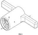
- Torque-limiting ratcheting driver 100may have a generally T-shaped handle or other structure to facilitate use by a user.
- the handlemay by "T-shaped.”
- the handlemay include arms 4 at one end of an axially extending generally hollow cylindrical body 6.
- Cap 2covers the same end of the handle. Cylindrical end 18 terminates cylindrical body 6 toward tip 12 of shaft 14.
- Cap 2may be snap-fitted to cylindrical body 6, or may be welded, adhered, or attached by any equivalent thereof.
- An exemplary implementationshows, at least in part, at cylindrical end 18, lower shank 700 provided, having an annularly tapering body and nose cone 8 along its length.
- Lower shank 700may have a plurality of support flanges 10 that add strength while saving material.
- lower shank 700tapers to drive socket 9 at the end of the nose cone 8 molded to engage drive connection 16 of shaft 14.
- An exemplary implementationshows, at least in part, shaft 14 provided, at one end, with work piece-engaging tip 12, adapted for engagement with an associated workpiece, such as a fastener or the like.
- the tipmay also be a resector or other blade instrument.
- Work piece-engaging tip 12is shown to be a socket wrench, but could be a screwdriver, wrench, or any other tool arrangement.
- lower shank 700has a plurality of gear 82 arranged in a crown gear formation 8, with circumferential rim 34 extending radially outward and an internal axial bore to accommodate at least a portion of shaft 14 extending there through.
- a clutch and ratchet assemblyinside cylindrical body 6 a clutch and ratchet assembly is disposed.
- the clutch assemblyincludes upper clutch shank 800 for forcibly engaging lower shank 700.
- Upper clutch shank 800has a bottom face that has a plurality of teeth 82 arranged in a crown gear formation around shaft guide 88 and a circumferential rim 83 extending radially outward and on the opposite side a plurality of drive body guides 202 each formed by an annular side wall 90, having passageways 200, a first interior wall 205 and second interior wall 207.
- the upper shankis cylindrical and of a size and shape to slide into the body 6 and rotate freely.
- upper clutch shank 800includes at least a plurality of passageways 200 through the annular side wall 90 of the upper clutch shank through which drive body 300 may extend.
- the annular side wall 90encircles the periphery of the upper clutch shank opposite the gear teeth and is the peripheral wall of each the drive body guide.
- washer 35maybe provided between circumferential rim 34 of lower shank 700 and circumferential flange 33 extending radially inward within the hollow of cylindrical body 6 forming a catch for the circumferential rim of the lower shank. Washer 35 may be of a polymer or other material having low coefficient of friction.
- circumferential rim 34 of lower shank 700may be provided flush against circumferential flange 33 of cylindrical body 6. The opposite side of circumferential flange 33 receives circumferential rim 83 of upper clutch shank 800, allowing gear teeth 82 of lower shank 700 to engage gear teeth 82 of upper clutch shank 800 when a torque is applied.
- Figure 2shows aspects of the inner annular wall of the body 6.
- teeth 405each protruding from the inner annular wall 402.
- Each toothhas at least a bearing surface 410 and a deflecting surface 415.
- the deflecting surface of each toothis angled in the same direction to form ramps from the inner annular wall 402 toward the bearing surface 410.
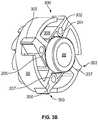
- FIGS 3A , 3B , and 4show aspects of an upper clutch shank 800 exploded, assembled and mounted.
- the upper clutch shank 800also forms the body of a ratchet device within the body 6.
- the upper clutch shank 800has gear teeth 82 forming a spiral crown gear on one side and a cylindrical cup shape, with guide openings, on the other side formed by an annular side wall 90.
- the cupis a open chamber with additional openings in the annular wall to allow toes to protrude and move within.
- the annular wallhas a series of openings fluidly connected to drive body guides 202 having mounting posts 204 formed therein.
- the drive body guides 202open through passageways 200 in the annular side wall 90. Movably mated to each mounting post 204 is a drive body 300.
- Each drive body 300is an elongated device divided roughly by a guide hole; it is multi-surfaced and each surface has a function.
- the posts guide 302mates to the mounting posts 204 to movably attach the drive body 300.
- a toe 303is at the most distal end of the drive body.
- An instep 305is an angled wall adjacent to the toe.
- the heel 306is a bearing surface adjacent to the instep 305.
- an ankle 308is on the opposite side of the post 204 then the toe. If the toe is at the distal end of the drive body the ankle is at the proximal end.
- the body guideis comprised of several walls which engage different portions of the drive body.
- the toe 303engages a bearing portion 410 of the ratchet tooth 405 and the heel 306 is a bearing surface against the second interior wall 207.
- the instepengages the deflecting surface 415 and the ankle 308 is urged against a first interior wall 205, whereby the ankle 308 formed of a size and thickness to have a predetermined amount of flex allows the drive body to move from a first position with the heel 306 against the second interior wall 207, to a second position at least partially remote from the interior wall, thereby rotating around the mounting post 204.
- the flexible ankle 308returns from the second position which is an under-load position, to the first at-rest position, thereby placing the toe in the proper orientation to engage a tooth's bearing surface 410 when the device is rotated in the locked direction, in this example indicated as a clockwise direction.
- the movable drive body or bodies in the cup shaped shankeach have a toe 303 protruding radially from the shank towards the inner annular wall 402.
- the drive bodies and drive body guidesshould be complementary size and shape. Those of ordinary skill in the art will recognize that it is within the scope of this disclosure that direction is a selectable feature and the ratchet teeth 405 may be reversed as well as the drive body guides 202. Moreover, the size and shape of the drive body, toe, ankle, instep and drive body guides may be varied.
- a disposable all-plastic ratchetis disclosed herein, the indication of its use with a torque limiting device is an exemplary implementation believed to be novel.
- the use of the ratcheting device with a non-torque limiting deviceis also within the scope of this disclosure.
- a non torque limiting devicewould be formed by permanently affixing the lower and upper shanks together thereby eliminating the gear 82 to gear 82 interaction and thereby providing a plastic disposable ratchet device to impart rotation to a shaft.
- One advantage of such a fixed torque configurationwould be to allow removal of the spring 22 and supporting washers which add weight and cost.
- the shaft 14is affixed in the nose 8 and the lower shank is inserted through cylindrical end 18 and in the cylindrical body top 19 the upper shank is inserted.
- the lower and upper shanksare permanently affixed to one another yet remain rotatable within the body.
- Figure 2shows ratchet teeth 405 oriented with the ramp function providing counterclockwise rotation of drive toe 305 whereby the toe does not engage the bearing surface 410 and therefore prevents a positive lock of the toe 303 at the bearing surface. Reversing the direction of both the deflecting surface would place the bearing surface in position for a positive lock in the counterclockwise direction if the drive bodies 300 were also mounted in a reverse orientation.
- forceis applied across lower shank 700 and upper clutch shank 800 via the coil spring 22 within cylindrical body 6.
- spacer 20 and washer 21are provided inside cylindrical body 6, shown in Figure 1 spacer 20 and washer 21 are provided.
- the washer 21is between upper clutch shank 800 and spring 22. Washer 21 transfers pressure from spring 22 over the top face of upper shank 800.
- washer 23 and shoulder nut 25hold spring 22 in a relatively compressed state. Washer 23 may be provided between nut 25 and spring 22 to facilitate relative rotation of nut 25 and spring 22.
- Nut 25is formed of material softer than shaft 14, nut 25 has an unobstructed open center 26 with a diameter smaller than the diameter of shaft 14 and a smooth surface malleable enough to be deformed by the rotational insertion to said open center 26 of the threading 17 at an end of shaft 14.
- Spring 22 and nut 25provide the proper tensioning and biasing for the clutch assembly and, generally, the nut 25 is adjustable relative to shaft 14 to provide proper tension and calibration.
- At least one of body 6, nut 25, lower shank 700, and upper clutch shank 800is of a plastic material or a composite including plastic.
- Plastic and other economical equivalentsimprove cost efficiency of production while providing high tensile strength, resistance to deformation, etc. Effective materials include plastics, resins, polymers, imides, fluoropolymers, thermoplastic polymers, thermosetting plastics, and the like as well as blends or mixtures thereof.
- at least one of lower shank 700 and upper shank 800is of or includes at least one material that lubricous or otherwise reduces friction. The presence of a friction-reducing material allows geometric aspects of the engagement between lower shank 700 and upper shank 800 to govern whether teeth engage or disengage, thereby improving precision of the device.
- materials and components of drive 100are resistant to sterilization, cleaning, and preparation operations.
- drive 100 and parts thereofare configured to withstand sterilization by methods including radiation (e.g., gamma rays, electron beam processing), steam (e.g., autoclave), detergents, chemical (e.g., Ethylene Oxide), heat, pressure, inter alia.
- materials for drive 100may be selected according to resistance to one or more selected sterilization techniques.
- shaft 14is of a rigid material.
- shaft 14may be of a metal, such as stainless steel.
- high torque capabilities of drive 100are, at least in part, provided by features that maintain an effective engagement between drive connection 16 of shaft 14 and drive socket 9 of lower shank 700.
- some exemplary implementationsare provided to improve the ability of drive 100 to maintain its grip on shaft 14 up to a greater range of torque.
- a single integrated shaft 14spans the distance between workpiece-engaging tip 12 and an engagement point with nut 25. This configuration enables greater torque capabilities than a piecemeal or fragmented set of interconnected components. This reduces the number of interconnections between a source of a torque and a location to which the torque is transferred.
- shaft 14 having drive connection 16 between opposing extensionsstabilizes drive connection 16 within drive socket 9. Placement of drive connection 16 at a medial segment of shaft 14- rather than at an end thereof- facilitates a more stable engagement between drive connection 16 and drive socket 9, thereby increasing the ability of engagement to transfer high amounts of torque.
- an engagement of drive connection 16 within drive socket 9is maintained by the connection of the integrated portion of shaft 14 that extends to nut 25.
- both threading 17 and drive connection 16are of a single integrated structure (i.e., shaft 14).
- a force applied by spring 22 to nut 25is directly transferred along shaft 14 from threading 17 to drive connection 16. This force securely maintains drive connection 16 within drive socket 9.
- This engagementenables transfers of greater amounts of torque from lower shank 700 (i.e., via drive socket 9) to shaft 14 (i.e., via drive connection 16).
- drive connection 16 and drive socket 9have complementary geometries.
- One or more of a variety of configurationsmay be provided for engaging drive connection 16 within drive socket 9.
- drives and associated connectionsmay include triangular, square, hexagonal, rectangular, etc.
- a substantially square drive connection 16 and drive socket 9provide high torque transfer capabilities. Out of a variety of drive types, experimental results demonstrated that square drives and connections were among the most successful at transferring high torque without failure.
- Drive connection 16 and drive socket 9may have rounded corners and edges to reduce or distribute stress risers.
- driver 100 capable of transferring higher torquemay be provided with spring 22 having a greater spring constant (i.e., force constant) or otherwise be calibrated with spring 22 exerting greater forces in an initial (rest) state.
- spring 22having a greater spring constant (i.e., force constant) or otherwise be calibrated with spring 22 exerting greater forces in an initial (rest) state.
- a more robust spring 22increases the probability of a friction grip relative to washer 21. Provision of additional spacer 20 provides counter clockwise rotation without increasing spring tension when the drive toes are disengaged from the load bearing surface 410.
- the plurality of teeth 82are formed on the top face of lower shank 700 and the bottom face of upper clutch shank 800 to forcibly engage to impart torque from the handle to the workpiece when a torque is applied.
- teeth 82are circumferentially spaced in a crown gear formation of the top face and bottom face of lower shank 700 and upper clutch shank 800, respectively.
- Teeth 82are preferably configured in a spiral formation.
- Each face of lower shank 700 and upper clutch shank 800has an inner radius and an outer radius and teeth 82 spiral around the inner radius resulting in a larger tooth detail when viewing the tooth from the outer radius relative to the tooth detail when viewing the tooth from the inner radius.
- the spiral configuration of teeth 82can also be defined as having a longer inclined face 66 at the edge of the tooth on or near the outer radius relative to inclined face 66 at the edge of the tooth on or near the inner radius of lower shank 700 and upper shank 800. Results have shown that teeth arranged in said spiral configuration provide an increased reliability and/or precision in torque consistency when compared to non-spiral counterparts.
- the extent to which threading 17 of shaft 14 is threaded into nut 25controls the amount of compression or preload on spring 22 which, subsequently, controls the limiting torque required to effect relative rotation of lower shank 700 and upper clutch shank 800. If shaft 14 is more deeply threaded into nut 25, then a higher torque will be required to disengage teeth 82 of lower shank 700 and upper clutch shank 800. If shaft 14 is less deeply threaded into nut 25, then a lower torque will be required. Accordingly, a predetermined torque limit is selectively programmable. The predetermined torque limit may correspond to a predefined threshold of a workpiece (e.g., a fastener) having a desired level of torque-based installation not to be exceeded.
- a workpiecee.g., a fastener
- teeth 82 of lower shank 700 and upper shank 800will continue to disengage, resulting in rotation of the handle with no further rotation of workpiece-engaging tip 12.
- the handlewill continue to rotate, disengaging teeth 82 with every rotational movement that will not impart continued force beyond a predefined threshold to the fastener.
- the disposable torque-limiting ratchet driver of the present disclosureis capable of imparting torques of up to about 13.5 Newton meters (120 inch-pounds).
- the torque output rangemay be selected between about 8 Newton meters (70 inch-pounds) and about 13.5 Newton meters (120 inch-pounds).
- the torque requirementis different for different operations and for different implants.
- applicationsmay include those in the field of orthopedic surgery, construction and emplacement of implants, etc. Therefore, in some instances, the predetermined torque limits maybe at least about 0.11 Newton meters (1 inch-pound). In other instances, the predetermined torque limit may be between about 0.56 Newton meters (5 inch-pounds) and about 17 Newton meters (150 inch-pounds), depending on an implant's specifications. In other instances, the predetermined torque limit may be between about 8 Newton meters (70 inch-pounds) and about 13.5 Newton meters (120 inch-pounds), depending on an implant's specifications.
- the driver 100may be prepackaged with an implant provided for one-time use. Such a methodology matches the driver that will impart a required amount of torque with the implant.
- the driver 100may be reusable.
- Shaft 14may be interchangeably fixed relative to nose cone 8 for the accommodation of multiple workpiece-engaging tips 12.
- the handle of the driveris not limited to a T-shape and may be provided in any other suitable configuration.
Landscapes
- Health & Medical Sciences (AREA)
- Engineering & Computer Science (AREA)
- Life Sciences & Earth Sciences (AREA)
- Surgery (AREA)
- Mechanical Engineering (AREA)
- Orthopedic Medicine & Surgery (AREA)
- General Health & Medical Sciences (AREA)
- Nuclear Medicine, Radiotherapy & Molecular Imaging (AREA)
- Heart & Thoracic Surgery (AREA)
- Medical Informatics (AREA)
- Molecular Biology (AREA)
- Animal Behavior & Ethology (AREA)
- Veterinary Medicine (AREA)
- Public Health (AREA)
- Biomedical Technology (AREA)
- Oral & Maxillofacial Surgery (AREA)
- Dentistry (AREA)
- Pathology (AREA)
- Orthopedics, Nursing, And Contraception (AREA)
- Details Of Spanners, Wrenches, And Screw Drivers And Accessories (AREA)
Description
- This disclosure relates to an inline disposable driver tool with plastic gear drive and, in particular, to a disposable medical use torque-limiting driver and ratchet that disengages at a predetermined torque limit. 2. General Background
- Torque is a measure of force acting on an object that causes that object to rotate. In the case of a driver and a fastener, this measurement can be calculated mathematically in terms of the cross product of specific vectors:

- Where r is the vector representing the distance and direction from an axis of a fastener to a point where the force is applied and F is the force vector acting on the driver.
- Torque has dimensions of force times distance and the SI unit of torque is the Newton meter (N-m). The joule, which is the SI unit for energy or work, is also defined as an N-m, but this unit is not used for torque. Since energy can be thought of as the result of force times distance, energy is always a scalar whereas torque is force cross-distance and so is a vector- valued quantity. Other non-SI units of torque include pound- force-feet, foot-pounds-force, ounce-force- inches, meter-kilograms-force, inch-ounces or inch-pounds.
- Torque-limiting drivers are widely used throughout the medical industry. These torque-limiting drivers have a factory pre-set torque to ensure the accuracy and toughness required to meet a demanding surgical environment.
- The medical industry has made use of both reusable and disposable torque-limiting drivers. In a surgical context, there is little room for error and these drivers must impart a precise amount of torque.
- Reusable drivers require constant recalibration to ensure that the driver is imparting the precise amount of torque. Recalibration is a cumbersome task but must be done routinely. Such reusable devices also require sterilization.
- Disposable drivers are an alternative to the reusable drivers. Once the driver has been used, it is discarded.
- Disposable drivers are traditionally used for low torque applications. The standard torque values in these applications typically range from about 0.03 Newton meters to 0.14 Newton meters (4 to about 20 inch-ounces). It has, however, been a challenge to develop a reliable disposable driver capable of imparting higher torques for larger applications.
- Piecemeal drivetrain systems have been developed to gear-up or otherwise impart greater torque with disposable devices. Such piecemeal systems provide interchangeability of parts to a device, within which torque is transferred from part-to-part of a piecemeal system.
- Ratchet is defined in Merriam- Webster dictionary as: a mechanism that consists of a bar or wheel having inclined teeth into which a pawl drops so that motion can be imparted to the wheel or bar, governed, or prevented and that is used in a hand tool (as a wrench or screwdriver) to allow effective motion in one direction only.
- Ratcheting medical wrenches are known they are traditional metal catch and metal pawl to impart directional application of force.
EP 0 287 823 A1 discloses a ratcheting medical wrench with a torque-limiting structure.FR 2 147 674 A5 - Briefly stated, torque devices according to implementations of the present disclosure obviate the shortfalls of piecemeal systems by reducing the number of part-to-part transitions of torque and ratcheting.
- Disclosed in some exemplary implementations herein are aspects of a torque-limiting ratchet driver. The driver has a cylindrical body. It may have a handle affixed thereto. The body has an inner annular wall; an upper clutch shank with gear teeth on one side and an annular wall around the periphery on the opposite side forming the peripheral wall of drive body guides; a lower shank having a drive socket on one side and gear teeth on the opposing side; a nut; a spacer; a coil spring between the upper cylindrical shank and the ribbed nut, wherein the spring is configured to apply a force across the upper clutch shank and the lower shank; a shaft having a workpiece-engaging tip and a drive connection engaged within the drive socket of the lower cylindrical shank, the shaft extending axially through the lower shank, the upper clutch shank, and the spring and connected to the nut; a plurality of ratchet teeth formed or molded on the inner annular wall; one or more of movable drive bodies mounted to the upper clutch shank with a toe that protrudes through a passageway beyond the annular wall to engage a ratchet tooth when rotated in the positive lock direction; wherein the upper shank and the lower clutch shank engage for relative rotation, and wherein the upper clutch shank and the lower shank disengage when a predetermined torque limit is exceeded; and, wherein the upper shank and the lower clutch shank move in the reverse direction without imparting torque. In some instance when the plurality of movable drive bodies move in the unlocked direction they do not engage the ratchet teeth.
- Disclosed in some exemplary implementations herein are aspects of a torque-limiting ratchet driver. The driver has a cylindrical body. It may have a handle affixed thereto. The body has an inner annular wall; an upper clutch shank with gear teeth on one side and an annular wall around the periphery on the opposite side forming the peripheral wall of drive body guides; a lower shank having a drive socket on one side and gear teeth on the opposing side; a nut; a spacer; a coil spring between the upper cylindrical shank and the ribbed nut, wherein the spring is configured to apply a force across the upper clutch shank and the lower shank; a shaft having a workpiece-engaging tip and a drive connection engaged within the drive socket of the lower cylindrical shank, the shaft extending axially through the lower shank, the upper clutch shank, and the spring and connected to the nut; a plurality of ratchet teeth formed or molded on the inner annular wall; one or more of movable drive bodies mounted to the upper clutch shank with a toe that protrudes through a passageway beyond the annular wall to engage a ratchet tooth when rotated in the positive lock direction; wherein the upper shank and the lower clutch shank engage for relative rotation, and wherein the upper clutch shank and the lower shank disengage when a predetermined torque limit is exceeded; wherein the upper shank and the lower clutch shank move in the reverse direction without imparting torque. In some instance the device further includes drive body guides; mounting posts within the drive body guides; a passageway fluidly connecting each drive body guide to the inner annular wall of the body; series of openings fluidly connecting drive body guides having mounting posts formed therein; and, whereby the toes protrude and may engage the ratchet teeth.
- In some instance the above implementations may have drive body(s) which include a post guide that mates with the mounting post; a toe, instep ; a heel; flexible ankle; a first interior wall; and, wherein the flexible ankle flexes against the first interior wall during ratcheting to allow the body to rotate in the unlocked without imparting torque to the tip.
- In some instance the above implementations may have drive body(s) which include a post guide that mates with the mounting post; a toe, instep; a heel; flexible ankle; a first interior wall; and, wherein each heel engages each of the second interior walls as bearing surfaces and locks the toes against the ratchet teeth.
- Disclosed in some exemplary implementations herein are aspects of a plastic ratchet mechanism having a cylindrical body with a with an inner annular wall, a cylindrical end, and a cylindrical top; a plurality of ratchet teeth formed or molded on the inner annular wall; a cup shaped cylindrical upper shank smaller than the interior diameter of the cylindrical body and having an annular wall around its periphery said annular wall forming the peripheral wall; drive body guides. In some instance the drive body guides have at least one passageway through the annular wall fluidly connecting each drive body guide to the inner annular wall of the body; at least one mounting post; one or more of movable drive bodies mounted to the cup shaped upper shank via the at least one mounting post; and, each drive body having a toe that protrudes through the passageway beyond the annular wall to engage a ratchet tooth when rotated in the positive lock direction.
- Disclosed in some exemplary implementations herein are aspects of a plastic ratchet mechanism having a cylindrical body with a with an inner annular wall, a cylindrical end, and a cylindrical top; a plurality of ratchet teeth formed or molded on the inner annular wall; a cup shaped cylindrical upper shank smaller than the interior diameter of the cylindrical body and having an annular wall around its periphery said annular wall forming the peripheral wall; drive body guides. In some instance the drive body guides have at least one passageway through the annular wall fluidly connecting each drive body guide to the inner annular wall of the body; at least one mounting post; one or more of movable drive bodies mounted to the cup shaped upper shank via the at least one mounting post; and, each drive body having a toe that protrudes through the passageway beyond the annular wall to engage a ratchet tooth when rotated in the positive lock direction; each drive body further comprises: a post guide that mates with the mounting post; a toe, instep; a heel; and, flexible ankle.
- In some instances a first interior wall; and, wherein the flexible ankle flexes against the first interior wall during ratcheting to allow the body to rotate in the unlocked without imparting rotation to the shank.
- In some instances a first interior wall; and, wherein each heel engages each of the second interior walls as bearing surfaces and locks the toes against the ratchet teeth.
- Disclosed in some exemplary implementations herein are aspects of a plastic ratchet mechanism having a cylindrical body with a with an inner annular wall, a cylindrical end, and a cylindrical top; a plurality of ratchet teeth formed or molded on the inner annular wall; a cup shaped cylindrical upper shank smaller than the interior diameter of the cylindrical body and having an annular wall around its periphery said annular wall forming the peripheral wall; drive body guides. In some instance the drive body guides have at least one passageway through the annular wall fluidly connecting each drive body guide to the inner annular wall of the body; at least one mounting post; one or more of movable drive bodies mounted to the cup shaped upper shank via the at least one mounting post; and, each drive body having a toe that protrudes through the passageway beyond the annular wall to engage a ratchet tooth when rotated in the positive lock direction; each drive body further comprises: a post guide that mates with the mounting post; a toe, instep; a heel; and, flexible ankle; a lower shank affixed to a shaft at its nose; a circumferential rim formed on the back side of the lower shank; and, a circumferential flange extending radially inward within the hollow of cylindrical body forming a catch for the circumferential rim of the lower shank. In some instance the shaft is attached to a fastener
Disclosed in some exemplary implementations herein are aspects of a plastic ratchet driving method to move a shaft. Placing within a hollow body having catches or teeth placed radially around an inner annular wall are a lower shank and and a cup shapedupper shank; affixed to the lower shank is a shaft with a tip at one end; placed within the body is a cup shaped upper shank; place within the cup shaped upper shank are a plurality of movable drive bodies each having a toe protruding radially from the shank towards the inner annular wall of the hollow body; and, connecting the toes to the teeth or catches around the inner annular wall rotating the shaft in a locked direction via rotating the body. In some instances rotating the body in an unlocked direction whereby the shaft does not rotate and the toes pass over the catches or teeth but do not engage. Rather the flexible ankles flex or bend and allow the drive body toe to pass over the catch without engagement. In some instances heels, flexible ankles, and an instep are formed on each drive body and each ankle flexes to allow the instep of the drive body to pass over the deflecting surface when rotating the body in an unlocked direction and the toes do not engage the bearing surface of the ratchet teeth. When rotated in a locking direction the instep of each drive body is placed under load via moving it against a bearing wall in the cup and each toe is also placed under load when it is moved against a bearing surface of a ratchet tooth. - Disclosed in some exemplary implementations herein are aspects of a disposable ratcheting device and method which includes at least a shaft extending axially through at least a shank. The shank also provides a cup or chamber wherein a series of drive bodies reside in a movable fashion. The shank is placed within a body having an inner wall with teeth formed radially, The drove bodies have flexible ankles on one side and toes on the other side. The toes protrude beyond the shank through passageways therein. When rotated in a locked direction the toes engage the teeth inside the body and impart rotation to the shaft. When rotated in an unlocked position the ankles flex allowing the toes to move over the teeth without engaging.
- The above-mentioned features of the present disclosure will become more apparent with reference to the following description taken in conjunction with the accompanying drawings wherein like reference numerals denote like elements and in which:
Figure 1 shows an assembly view of some aspects of a torque limiting ratchet driver;Figure 2 shows the ratchet catch teeth inside a body;Figure 3A and3B show assembly and assembled view of the ratchet drive fingers;Figure 4 shows a back to front view of the ratchet drive fingers mounted in the body;Figure 5 shows a front to back view of the body with mounted upper clutch shank mechanism.- While the specification concludes with claims defining the features of the present disclosure that are regarded as novel, it is believed that the present disclosure's teachings will be better understood from a consideration of the following description in conjunction with the appendices, figures, in which like reference numerals are carried forward. All descriptions and callouts in the Figures are hereby incorporated by this reference as if fully set forth herein.
- According to one or more exemplary implementations, as shown in
Figures 1-5 torque-limitingratcheting driver 100 are provided. Torque-limitingratcheting driver 100 may have a generally T-shaped handle or other structure to facilitate use by a user. For example, the handle may by "T-shaped." The handle may includearms 4 at one end of an axially extending generally hollowcylindrical body 6.Cap 2 covers the same end of the handle.Cylindrical end 18 terminatescylindrical body 6 towardtip 12 ofshaft 14.Cap 2 may be snap-fitted tocylindrical body 6, or may be welded, adhered, or attached by any equivalent thereof. - An exemplary implementation shows, at least in part, at
cylindrical end 18,lower shank 700 provided, having an annularly tapering body and nose cone 8 along its length.Lower shank 700 may have a plurality ofsupport flanges 10 that add strength while saving material. At one end,lower shank 700 tapers to drive socket 9 at the end of the nose cone 8 molded to engagedrive connection 16 ofshaft 14. An exemplary implementation shows, at least in part,shaft 14 provided, at one end, with work piece-engagingtip 12, adapted for engagement with an associated workpiece, such as a fastener or the like. The tip may also be a resector or other blade instrument. Work piece-engagingtip 12 is shown to be a socket wrench, but could be a screwdriver, wrench, or any other tool arrangement. During use as a torque limiting device the tip is connected to a fastener or the work piece. The tip can only be rotated by apply force visa vie rotating the body and the associated upper and lower shanks acting as a clutch within. During use as a ratchet only the device the tip is connected to a fastener or the work piece. The tip can only be rotated by apply force visa vie rotating the body and the associated ratcheting mechanism described below. At an opposite end,lower shank 700 has a plurality ofgear 82 arranged in a crown gear formation 8, withcircumferential rim 34 extending radially outward and an internal axial bore to accommodate at least a portion ofshaft 14 extending there through. - According to aspects of one or more exemplary implementations, inside cylindrical body 6 a clutch and ratchet assembly is disposed. The clutch assembly includes upper
clutch shank 800 for forcibly engaginglower shank 700. Upperclutch shank 800 has a bottom face that has a plurality ofteeth 82 arranged in a crown gear formation aroundshaft guide 88 and acircumferential rim 83 extending radially outward and on the opposite side a plurality of drive body guides 202 each formed by anannular side wall 90, havingpassageways 200, a firstinterior wall 205 and secondinterior wall 207. The upper shank is cylindrical and of a size and shape to slide into thebody 6 and rotate freely. - According to one or more exemplary implementations, upper
clutch shank 800 includes at least a plurality ofpassageways 200 through theannular side wall 90 of the upper clutch shank through which drivebody 300 may extend. Theannular side wall 90 encircles the periphery of the upper clutch shank opposite the gear teeth and is the peripheral wall of each the drive body guide. - In assembly,
drive connection 16 ofshaft 14 is received into drive socket 9 oflower shank 700.Washer 35 maybe provided betweencircumferential rim 34 oflower shank 700 andcircumferential flange 33 extending radially inward within the hollow ofcylindrical body 6 forming a catch for the circumferential rim of the lower shank.Washer 35 may be of a polymer or other material having low coefficient of friction. Alternatively,circumferential rim 34 oflower shank 700 may be provided flush againstcircumferential flange 33 ofcylindrical body 6. The opposite side ofcircumferential flange 33 receivescircumferential rim 83 of upperclutch shank 800, allowinggear teeth 82 oflower shank 700 to engagegear teeth 82 of upperclutch shank 800 when a torque is applied. Figure 2 shows aspects of the inner annular wall of thebody 6. Formed or molded as part of the innerannular wall 402 of thecylindrical body 6 areteeth 405 each protruding from the innerannular wall 402. Each tooth has at least abearing surface 410 and a deflectingsurface 415. The deflecting surface of each tooth is angled in the same direction to form ramps from the innerannular wall 402 toward the bearingsurface 410.Figures 3A ,3B , and4 show aspects of an upperclutch shank 800 exploded, assembled and mounted. The upperclutch shank 800 also forms the body of a ratchet device within thebody 6. The upperclutch shank 800 hasgear teeth 82 forming a spiral crown gear on one side and a cylindrical cup shape, with guide openings, on the other side formed by anannular side wall 90. The cup is a open chamber with additional openings in the annular wall to allow toes to protrude and move within. The annular wall has a series of openings fluidly connected to drive body guides 202 having mountingposts 204 formed therein. The drive body guides 202 open throughpassageways 200 in theannular side wall 90. Movably mated to each mountingpost 204 is adrive body 300. Eachdrive body 300 is an elongated device divided roughly by a guide hole; it is multi-surfaced and each surface has a function. The posts guide 302 mates to the mountingposts 204 to movably attach thedrive body 300. Atoe 303 is at the most distal end of the drive body. Aninstep 305 is an angled wall adjacent to the toe. Theheel 306 is a bearing surface adjacent to theinstep 305. And anankle 308 is on the opposite side of thepost 204 then the toe. If the toe is at the distal end of the drive body the ankle is at the proximal end. The body guide is comprised of several walls which engage different portions of the drive body. In positive lock use as shown inFigure 4 , thetoe 303 engages a bearingportion 410 of theratchet tooth 405 and theheel 306 is a bearing surface against the secondinterior wall 207. In the unlocked state the instep engages the deflectingsurface 415 and theankle 308 is urged against a firstinterior wall 205, whereby theankle 308 formed of a size and thickness to have a predetermined amount of flex allows the drive body to move from a first position with theheel 306 against the secondinterior wall 207, to a second position at least partially remote from the interior wall, thereby rotating around the mountingpost 204. When the instep passes over theratchet tooth 405, theflexible ankle 308 returns from the second position which is an under-load position, to the first at-rest position, thereby placing the toe in the proper orientation to engage a tooth'sbearing surface 410 when the device is rotated in the locked direction, in this example indicated as a clockwise direction. The movable drive body or bodies in the cup shaped shank each have atoe 303 protruding radially from the shank towards the innerannular wall 402.- The drive bodies and drive body guides should be complementary size and shape. Those of ordinary skill in the art will recognize that it is within the scope of this disclosure that direction is a selectable feature and the
ratchet teeth 405 may be reversed as well as the drive body guides 202. Moreover, the size and shape of the drive body, toe, ankle, instep and drive body guides may be varied. - Those of ordinary skill in the art will recognize that a disposable all-plastic ratchet is disclosed herein, the indication of its use with a torque limiting device is an exemplary implementation believed to be novel. The use of the ratcheting device with a non-torque limiting device is also within the scope of this disclosure. A non torque limiting device would be formed by permanently affixing the lower and upper shanks together thereby eliminating the
gear 82 to gear 82 interaction and thereby providing a plastic disposable ratchet device to impart rotation to a shaft. One advantage of such a fixed torque configuration would be to allow removal of thespring 22 and supporting washers which add weight and cost. In such a configuration theshaft 14 is affixed in the nose 8 and the lower shank is inserted throughcylindrical end 18 and in thecylindrical body top 19 the upper shank is inserted. The lower and upper shanks are permanently affixed to one another yet remain rotatable within the body. Figure 2 shows ratchetteeth 405 oriented with the ramp function providing counterclockwise rotation ofdrive toe 305 whereby the toe does not engage thebearing surface 410 and therefore prevents a positive lock of thetoe 303 at the bearing surface. Reversing the direction of both the deflecting surface would place the bearing surface in position for a positive lock in the counterclockwise direction if thedrive bodies 300 were also mounted in a reverse orientation.- According to aspects of one or more exemplary implementations, force is applied across
lower shank 700 and upperclutch shank 800 via thecoil spring 22 withincylindrical body 6. Insidecylindrical body 6, shown inFigure 1 spacer 20 andwasher 21 are provided. Thewasher 21 is between upperclutch shank 800 andspring 22.Washer 21 transfers pressure fromspring 22 over the top face ofupper shank 800. At an end ofspring 22 opposite upperclutch shank 800,washer 23 andshoulder nut 25hold spring 22 in a relatively compressed state.Washer 23 may be provided betweennut 25 andspring 22 to facilitate relative rotation ofnut 25 andspring 22.Nut 25 is formed of material softer thanshaft 14,nut 25 has an unobstructedopen center 26 with a diameter smaller than the diameter ofshaft 14 and a smooth surface malleable enough to be deformed by the rotational insertion to saidopen center 26 of the threading 17 at an end ofshaft 14. - According to one or more exemplary implementations,
shaft 14 having threading 17 at an end opposite workpiece-engagingtip 12 engages a complementary threading withinnut 25, thereby imparting pressure between therespective teeth 82 oflower shank 700 and upperclutch shank 800.Spring 22 andnut 25 provide the proper tensioning and biasing for the clutch assembly and, generally, thenut 25 is adjustable relative toshaft 14 to provide proper tension and calibration. - According to aspects of one or more exemplary implementations, various materials may be used for the components of
driver 100. According to some exemplary implementations, at least one ofbody 6,nut 25,lower shank 700, and upperclutch shank 800 is of a plastic material or a composite including plastic. Plastic and other economical equivalents improve cost efficiency of production while providing high tensile strength, resistance to deformation, etc. Effective materials include plastics, resins, polymers, imides, fluoropolymers, thermoplastic polymers, thermosetting plastics, and the like as well as blends or mixtures thereof. According to aspects of one or more exemplary implementations, at least one oflower shank 700 andupper shank 800 is of or includes at least one material that lubricous or otherwise reduces friction. The presence of a friction-reducing material allows geometric aspects of the engagement betweenlower shank 700 andupper shank 800 to govern whether teeth engage or disengage, thereby improving precision of the device. - According to aspects of one or more exemplary implementations, materials and components of
drive 100 are resistant to sterilization, cleaning, and preparation operations. For example, drive 100 and parts thereof are configured to withstand sterilization by methods including radiation (e.g., gamma rays, electron beam processing), steam (e.g., autoclave), detergents, chemical (e.g., Ethylene Oxide), heat, pressure, inter alia. For example, materials fordrive 100 may be selected according to resistance to one or more selected sterilization techniques. - According to aspects of one or more exemplary implementations,
shaft 14 is of a rigid material. For example,shaft 14 may be of a metal, such as stainless steel. According to some exemplary implementations, high torque capabilities ofdrive 100 are, at least in part, provided by features that maintain an effective engagement betweendrive connection 16 ofshaft 14 and drive socket 9 oflower shank 700. For example, some exemplary implementations are provided to improve the ability ofdrive 100 to maintain its grip onshaft 14 up to a greater range of torque. - According to aspects of one or more exemplary implementations, a single
integrated shaft 14 spans the distance between workpiece-engagingtip 12 and an engagement point withnut 25. This configuration enables greater torque capabilities than a piecemeal or fragmented set of interconnected components. This reduces the number of interconnections between a source of a torque and a location to which the torque is transferred. - According to one or more exemplary implementations,
shaft 14 havingdrive connection 16 between opposing extensions stabilizesdrive connection 16 within drive socket 9. Placement ofdrive connection 16 at a medial segment of shaft 14- rather than at an end thereof- facilitates a more stable engagement betweendrive connection 16 and drive socket 9, thereby increasing the ability of engagement to transfer high amounts of torque. - According to one or more exemplary implementations, an engagement of
drive connection 16 within drive socket 9 is maintained by the connection of the integrated portion ofshaft 14 that extends tonut 25. According to some exemplary implementations, both threading 17 and driveconnection 16 are of a single integrated structure (i.e., shaft 14). A force applied byspring 22 tonut 25 is directly transferred alongshaft 14 from threading 17 to driveconnection 16. This force securely maintainsdrive connection 16 within drive socket 9. This engagement enables transfers of greater amounts of torque from lower shank 700 (i.e., via drive socket 9) to shaft 14 (i.e., via drive connection 16). - According to aspects of some exemplary implementations,
drive connection 16 and drive socket 9 have complementary geometries. One or more of a variety of configurations may be provided for engagingdrive connection 16 within drive socket 9. For example drives and associated connections may include triangular, square, hexagonal, rectangular, etc. According to aspects of one or more exemplary implementations, a substantiallysquare drive connection 16 and drive socket 9 provide high torque transfer capabilities. Out of a variety of drive types, experimental results demonstrated that square drives and connections were among the most successful at transferring high torque without failure.Drive connection 16 and drive socket 9 may have rounded corners and edges to reduce or distribute stress risers. - According to aspects of one or more exemplary implementations,
driver 100 capable of transferring higher torque may be provided withspring 22 having a greater spring constant (i.e., force constant) or otherwise be calibrated withspring 22 exerting greater forces in an initial (rest) state. A morerobust spring 22 increases the probability of a friction grip relative towasher 21. Provision ofadditional spacer 20 provides counter clockwise rotation without increasing spring tension when the drive toes are disengaged from theload bearing surface 410. - According to aspects of one or more exemplary implementations, the plurality of
teeth 82 are formed on the top face oflower shank 700 and the bottom face of upperclutch shank 800 to forcibly engage to impart torque from the handle to the workpiece when a torque is applied. - According to aspects of one or more exemplary implementations,
teeth 82 are circumferentially spaced in a crown gear formation of the top face and bottom face oflower shank 700 and upperclutch shank 800, respectively.Teeth 82 are preferably configured in a spiral formation. Each face oflower shank 700 and upperclutch shank 800 has an inner radius and an outer radius andteeth 82 spiral around the inner radius resulting in a larger tooth detail when viewing the tooth from the outer radius relative to the tooth detail when viewing the tooth from the inner radius. The spiral configuration ofteeth 82 can also be defined as having a longer inclined face 66 at the edge of the tooth on or near the outer radius relative to inclined face 66 at the edge of the tooth on or near the inner radius oflower shank 700 andupper shank 800. Results have shown that teeth arranged in said spiral configuration provide an increased reliability and/or precision in torque consistency when compared to non-spiral counterparts. - According to aspects of one or more exemplary implementations, the extent to which threading 17 of
shaft 14 is threaded intonut 25 controls the amount of compression or preload onspring 22 which, subsequently, controls the limiting torque required to effect relative rotation oflower shank 700 and upperclutch shank 800. Ifshaft 14 is more deeply threaded intonut 25, then a higher torque will be required to disengageteeth 82 oflower shank 700 and upperclutch shank 800. Ifshaft 14 is less deeply threaded intonut 25, then a lower torque will be required. Accordingly, a predetermined torque limit is selectively programmable. The predetermined torque limit may correspond to a predefined threshold of a workpiece (e.g., a fastener) having a desired level of torque-based installation not to be exceeded. - When a force beyond the predetermined torque limit is achieved,
teeth 82 oflower shank 700 andupper shank 800 will continue to disengage, resulting in rotation of the handle with no further rotation of workpiece-engagingtip 12. Thus, the handle will continue to rotate, disengagingteeth 82 with every rotational movement that will not impart continued force beyond a predefined threshold to the fastener. - According to aspects of one or more exemplary implementations, the disposable torque-limiting ratchet driver of the present disclosure is capable of imparting torques of up to about 13.5 Newton meters (120 inch-pounds). For example, the torque output range may be selected between about 8 Newton meters (70 inch-pounds) and about 13.5 Newton meters (120 inch-pounds). Typically, the torque requirement is different for different operations and for different implants. For example, applications may include those in the field of orthopedic surgery, construction and emplacement of implants, etc. Therefore, in some instances, the predetermined torque limits maybe at least about 0.11 Newton meters (1 inch-pound). In other instances, the predetermined torque limit may be between about 0.56 Newton meters (5 inch-pounds) and about 17 Newton meters (150 inch-pounds), depending on an implant's specifications. In other instances, the predetermined torque limit may be between about 8 Newton meters (70 inch-pounds) and about 13.5 Newton meters (120 inch-pounds), depending on an implant's specifications.
- In some instances, the
driver 100 may be prepackaged with an implant provided for one-time use. Such a methodology matches the driver that will impart a required amount of torque with the implant. - In other instances, the
driver 100 may be reusable.Shaft 14 may be interchangeably fixed relative to nose cone 8 for the accommodation of multiple workpiece-engagingtips 12. It is also to be appreciated that the handle of the driver is not limited to a T-shape and may be provided in any other suitable configuration.

Claims (8)
- A torque-limiting ratchet driver comprising:a body (6) having a handle (4) and an inner annular wall (402);an upper clutch shank (800) with gear teeth (83) on one side and an annular wall (90) around the periphery on the opposite side forming the peripheral wall of drive body guides (202);a lower shank (700) having a drive socket (9) on one side and gear teeth (83) on the opposing side;a nut (25);a spring (22) with an outer and an inner diameter between the upper clutch shank and the nut, wherein the spring is configured to apply a force across the upper clutch shank and the lower shank;a shaft (14) having a workpiece-engaging tip (12) and a drive connection (16) engaged within the drive socket of the lower shank, the shaft extending axially through the lower shank, the upper clutch shank, and the spring and connected to the nut;a plurality of ratchet teeth (405) formed or molded on the inner annular wall (402);one or more of movable drive bodies (300) mounted to the upper clutch shank with a toe (303) that protrudes through a passageway (200) beyond the annular wall to engage a ratchet tooth when rotated in the positive lock direction;wherein the upper clutch shank and the lower shank engage for relative rotation, and wherein the upper clutch shank and the lower shank disengage when a predetermined torque limit is exceeded; and,wherein when the body rotates in an unlocked direction the toes disengage from the ratchet teeth and the shaft does not rotate.
- The torque-limiting ratchet driver of claim 1 further comprising:drive body guides (202);mounting posts (204) within the drive body guides;a passageway (200) fluidly connecting each drive body guide to the inner annular wall of the body;series of openings fluidly connecting drive body guides having mounting posts formed therein; and,whereby the toes protrude and may engage the ratchet teeth.
- The torque-limiting ratchet driver of claim 2 wherein each drive body (300) includes:a post guide (302) that mates with the mounting post, the post guide disposed in a medial portion of the drive body between a proximal end and a distal end, the toe disposed on the distal end of the drive body;an instep (305) adjacent to the toe;a heel (306) adjacent to the instep; and,a flexible ankle (308) on the proximal end of the drive body.
- The torque-limiting ratchet driver of claim 3 further comprising:a first interior wall (205); and,wherein the flexible ankle flexes against the first interior wall during ratcheting to allow the body to rotate in the unlocked direction without imparting torque to the tip.
- The torque-limiting ratchet driver of claim 3 further comprising:a first interior wall (205); and,wherein each heel engages each of respective second interior walls (207) as bearing surfaces and locks the toes against the ratchet teeth.
- The torque-limiting ratchet driver of claim 3 further comprising:a second interior wall (207); and,wherein each ankle flexes against each of respective first interior walls and the insteps pass over deflecting surfaces (415) of each ratchet tooth.
- The torque-limiting ratchet driver of claim 3 further comprising:a circumferential rim (34) formed on the back side of the lower shank; and,a circumferential flange (33) extending radially inward within the hollow of cylindrical body (6) forming a catch for the circumferential rim of the lower shank.
- The torque-limiting ratchet driver of claim 4 or claim 5 further comprising:a circumferential rim (34) formed on the back side of the lower shank; and,a circumferential flange (33) extending radially inward within the hollow of cylindrical body (6) forming a catch for the circumferential rim of the lower shank; and,wherein the shaft is attached to a fastener.
Applications Claiming Priority (2)
| Application Number | Priority Date | Filing Date | Title |
|---|---|---|---|
| US201361777765P | 2013-03-12 | 2013-03-12 | |
| PCT/US2014/021755WO2014164293A2 (en) | 2013-03-12 | 2014-03-07 | Ratcheting torque wrench |
Publications (3)
| Publication Number | Publication Date |
|---|---|
| EP2969395A2 EP2969395A2 (en) | 2016-01-20 |
| EP2969395A4 EP2969395A4 (en) | 2016-03-16 |
| EP2969395B1true EP2969395B1 (en) | 2018-10-10 |
Family
ID=51659296
Family Applications (1)
| Application Number | Title | Priority Date | Filing Date |
|---|---|---|---|
| EP14778491.2AActiveEP2969395B1 (en) | 2013-03-12 | 2014-03-07 | Ratcheting torque wrench |
Country Status (4)
| Country | Link |
|---|---|
| US (2) | US9446507B2 (en) |
| EP (1) | EP2969395B1 (en) |
| CA (1) | CA2903436C (en) |
| WO (1) | WO2014164293A2 (en) |
Cited By (1)
| Publication number | Priority date | Publication date | Assignee | Title |
|---|---|---|---|---|
| EP4387812A4 (en)* | 2021-08-18 | 2025-06-18 | Milwaukee Electric Tool Corporation | CLUTCH ASSEMBLY FOR A POWER TOOL |
Families Citing this family (44)
| Publication number | Priority date | Publication date | Assignee | Title |
|---|---|---|---|---|
| EP2969395B1 (en)* | 2013-03-12 | 2018-10-10 | ECA Medical Instruments | Ratcheting torque wrench |
| US9480574B2 (en) | 2013-03-14 | 2016-11-01 | Benvenue Medical, Inc. | Spinal fusion implants and devices and methods for deploying such implants |
| EP3125773B1 (en)* | 2014-04-01 | 2022-10-19 | ECA Medical Instruments | Modular clutch assembly |
| US10314605B2 (en) | 2014-07-08 | 2019-06-11 | Benvenue Medical, Inc. | Apparatus and methods for disrupting intervertebral disc tissue |
| US10335930B2 (en)* | 2014-10-14 | 2019-07-02 | Lomak Industrial Company Limited | Shaft ratchet release and sealing mechanism |
| EP3232940B1 (en)* | 2014-12-18 | 2021-05-05 | ECA Medical Instruments | Disposable bidirectional ratchet |
| US10022243B2 (en) | 2015-02-06 | 2018-07-17 | Benvenue Medical, Inc. | Graft material injector system and method |
| DE102015111877A1 (en)* | 2015-07-22 | 2017-01-26 | Aesculap Ag | Tool holder for surgical drill with additional manual drive unit and surgical drill |
| DE102015111878A1 (en) | 2015-07-22 | 2017-01-26 | Aesculap Ag | Space-saving Rat unit with freewheel |
| US10213270B2 (en)* | 2015-12-02 | 2019-02-26 | Lomack Industrial Co. Ltd. | Small disposable torque limiting driving tool with rubber grip |
| US10743892B2 (en)* | 2016-01-27 | 2020-08-18 | Stryker European Holdings I, Llc | Surgical instruments and methods |
| WO2018144934A1 (en)* | 2017-02-03 | 2018-08-09 | Plehn Citrone David | Hand tool |
| US10758286B2 (en) | 2017-03-22 | 2020-09-01 | Benvenue Medical, Inc. | Minimal impact access system to disc space |
| US10973558B2 (en) | 2017-06-12 | 2021-04-13 | K2M, Inc. | Screw insertion instrument and methods of use |
| US10730167B2 (en)* | 2017-07-19 | 2020-08-04 | Zimmer, Inc. | Disposable surgical screwdriver |
| WO2019148083A1 (en) | 2018-01-29 | 2019-08-01 | Benvenue Medical, Inc. | Minimally invasive interbody fusion |
| WO2019178575A1 (en)* | 2018-03-16 | 2019-09-19 | Benvenue Medical, Inc. | Articulated instrumentation and methods of using the same |
| CN208697287U (en) | 2018-07-25 | 2019-04-05 | 北京水木天蓬医疗技术有限公司 | Torque wrench of ultrasonic knife |
| US11311314B2 (en) | 2018-07-31 | 2022-04-26 | GetSet Surgical SA | Spinal surgery systems and methods |
| USD896384S1 (en) | 2019-06-07 | 2020-09-15 | GetSet Surgical SA | Spinal fusion cage |
| USD926978S1 (en) | 2019-06-07 | 2021-08-03 | GetSet Surgical SA | Surgical instrument handle |
| USD926312S1 (en) | 2019-06-07 | 2021-07-27 | GetSet Surgical SA | Surgical instrument handle |
| USD927687S1 (en) | 2019-06-07 | 2021-08-10 | GetSet Surgical SA | Surgical instrument handle |
| US11759235B2 (en) | 2019-09-27 | 2023-09-19 | Bard Access Systems, Inc. | Constant-torque intraosseous access devices and methods thereof |
| CN212879457U (en) | 2019-09-27 | 2021-04-06 | 巴德阿克塞斯系统股份有限公司 | Self-advancing intraosseous access device and intraosseous access device |
| US11730529B2 (en) | 2020-03-26 | 2023-08-22 | Warsaw Orthopedic, Inc. | Powered modular head locker |
| US12004782B2 (en) | 2020-03-26 | 2024-06-11 | Warsaw Orthopedic, Inc. | Instrument for locking orthopedic screws |
| US12023014B2 (en) | 2020-04-10 | 2024-07-02 | Nextremity Solutions, Inc. | Ratcheting handle for medical instrument |
| US11944502B2 (en) | 2020-04-10 | 2024-04-02 | Medartis Ag | Torque limiting ratcheting handle for medical instrument |
| US20210315656A1 (en)* | 2020-04-10 | 2021-10-14 | Nextremity Solutions, Inc. | Torque limiting handle for medical instrument |
| WO2021216521A1 (en)* | 2020-04-21 | 2021-10-28 | Bard Access Systems , Inc. | Reusable push-activated intraosseous access device |
| US12208035B2 (en) | 2020-04-27 | 2025-01-28 | Johnson & Johnson Surgical Vision, Inc. | Apparatus and system for a disposable torque limiting tip wrench |
| CN113749724A (en) | 2020-06-03 | 2021-12-07 | 巴德阿克塞斯系统股份有限公司 | Intraosseous device including sensing obturator |
| CN216628654U (en) | 2020-08-25 | 2022-05-31 | 巴德阿克塞斯系统股份有限公司 | Angled intraosseous access system |
| CN215839325U (en) | 2020-09-09 | 2022-02-18 | 巴德阿克塞斯系统股份有限公司 | Suction device for an intraosseous access system |
| US12262927B2 (en) | 2020-12-10 | 2025-04-01 | K2M, Inc. | Screw insertion instrument and methods of use |
| CN112603499B (en)* | 2020-12-29 | 2022-09-27 | 南京佗道医疗科技有限公司 | Puncture imbedding device |
| CN217960227U (en) | 2021-02-08 | 2022-12-06 | 巴德阿克塞斯系统股份有限公司 | Intraosseous access system |
| US11291477B1 (en) | 2021-05-04 | 2022-04-05 | Warsaw Orthopedic, Inc. | Dorsal adjusting implant and methods of use |
| US11432848B1 (en) | 2021-05-12 | 2022-09-06 | Warsaw Orthopedic, Inc. | Top loading quick lock construct |
| US11712270B2 (en) | 2021-05-17 | 2023-08-01 | Warsaw Orthopedic, Inc. | Quick lock clamp constructs and associated methods |
| EP4219241B1 (en)* | 2021-05-27 | 2025-01-22 | Thule Sweden AB | Tightening member |
| US11957391B2 (en) | 2021-11-01 | 2024-04-16 | Warsaw Orthopedic, Inc. | Bone screw having an overmold of a shank |
| TWI890553B (en)* | 2024-08-14 | 2025-07-11 | 義成工廠股份有限公司 | Ratchet wrench assembly structure |
Family Cites Families (21)
| Publication number | Priority date | Publication date | Assignee | Title |
|---|---|---|---|---|
| US2773574A (en)* | 1954-03-08 | 1956-12-11 | Sweeney Mfg Co B K | Ratchet adapters for socket wrenches |
| US3742787A (en) | 1971-07-26 | 1973-07-03 | Creative Tools | Reversible drive ratchet hand tool with spherical handle |
| GB8624566D0 (en)* | 1986-10-14 | 1986-11-19 | Manwaring A | Spanner/wrench assembly |
| DE3709824A1 (en)* | 1987-03-25 | 1988-10-06 | Heinl Thomas | SURGICAL HAND TOOL |
| US7066054B2 (en)* | 2004-03-19 | 2006-06-27 | Kuo-Chen Liu | Ratchet wrench |
| US7334509B1 (en)* | 2006-10-11 | 2008-02-26 | Bradshaw Medical, Inc. | Torque limiting driver and assembly |
| US9010509B2 (en)* | 2006-12-15 | 2015-04-21 | Sp Air Kabushiki Kaisha | Ratchet drive for a ratchet wrench |
| US7762164B2 (en)* | 2008-06-02 | 2010-07-27 | Eca Medical Instruments | Torque-limiting device |
| US20090293683A1 (en)* | 2008-06-02 | 2009-12-03 | Chia-Yu Chen | Ratchet driver |
| US8276487B2 (en) | 2009-04-30 | 2012-10-02 | Medtronic, Inc. | Torque wrench for implantable medical devices |
| US8051746B2 (en)* | 2009-06-30 | 2011-11-08 | Ingersoll Rand Company | Ratchet wrench with collar-actuated reversing mechanism |
| US8051751B2 (en)* | 2009-07-17 | 2011-11-08 | Hern Juei Co., Ltd. | Lockable torque-limiting driver |
| US8104383B2 (en)* | 2009-10-22 | 2012-01-31 | Jin-Tsai Lai | Torque socket assembly |
| US20110094348A1 (en)* | 2009-10-27 | 2011-04-28 | Jack Lee | Open end ratchet wrench |
| WO2011139902A2 (en)* | 2010-05-06 | 2011-11-10 | Eca Medical Instruments | Ultra high torque device |
| US20120036966A1 (en)* | 2010-08-10 | 2012-02-16 | Hong-Jen Lee | Ratchet wrench with reversible mechanism |
| ITTO20120492A1 (en)* | 2012-06-06 | 2013-12-07 | Lamp S R L | TORQUE CONTROL SCREWDRIVER FOR MEDICAL USE |
| US9475178B2 (en)* | 2012-10-23 | 2016-10-25 | Stanley Black & Decker, Inc. | Adjustable ratcheting socket wrench |
| EP2969395B1 (en)* | 2013-03-12 | 2018-10-10 | ECA Medical Instruments | Ratcheting torque wrench |
| US10194988B2 (en) | 2014-01-17 | 2019-02-05 | DePuy Synthes Products, Inc. | Torque limiting instrument |
| EP3232940B1 (en)* | 2014-12-18 | 2021-05-05 | ECA Medical Instruments | Disposable bidirectional ratchet |
- 2014
- 2014-03-07EPEP14778491.2Apatent/EP2969395B1/enactiveActive
- 2014-03-07CACA2903436Apatent/CA2903436C/enactiveActive
- 2014-03-07WOPCT/US2014/021755patent/WO2014164293A2/enactiveApplication Filing
- 2015
- 2015-08-27USUS14/837,523patent/US9446507B2/enactiveActive
- 2016
- 2016-08-17USUS15/239,685patent/US10195724B2/enactiveActive
Non-Patent Citations (1)
| Title |
|---|
| None* |
Cited By (1)
| Publication number | Priority date | Publication date | Assignee | Title |
|---|---|---|---|---|
| EP4387812A4 (en)* | 2021-08-18 | 2025-06-18 | Milwaukee Electric Tool Corporation | CLUTCH ASSEMBLY FOR A POWER TOOL |
Also Published As
| Publication number | Publication date |
|---|---|
| US20150367487A1 (en) | 2015-12-24 |
| CA2903436A1 (en) | 2014-10-09 |
| EP2969395A4 (en) | 2016-03-16 |
| EP2969395A2 (en) | 2016-01-20 |
| US20160354907A1 (en) | 2016-12-08 |
| US10195724B2 (en) | 2019-02-05 |
| WO2014164293A2 (en) | 2014-10-09 |
| CA2903436C (en) | 2017-08-01 |
| WO2014164293A3 (en) | 2014-11-27 |
| US9446507B2 (en) | 2016-09-20 |
Similar Documents
| Publication | Publication Date | Title |
|---|---|---|
| EP2969395B1 (en) | Ratcheting torque wrench | |
| EP2675595B1 (en) | International application for enhanced high torque device | |
| EP2566411B1 (en) | Ultra high torque device | |
| EP2598293B1 (en) | Cannulated torque device and tip engagement | |
| EP2566412B1 (en) | Cannulated ultra high torque device | |
| US7762164B2 (en) | Torque-limiting device | |
| EP2675594B1 (en) | Robust nose torque-limiting device | |
| EP2948093B1 (en) | In-line disposable torque limiting device suitable for power drive | |
| US10279146B2 (en) | Cannulated disposable torque limiting device with plastic shaft | |
| EP3125773B1 (en) | Modular clutch assembly | |
| US10920833B2 (en) | Gearless torque drive | |
| EP2948078B1 (en) | Fortified plastic disposable torque devices |
Legal Events
| Date | Code | Title | Description |
|---|---|---|---|
| PUAI | Public reference made under article 153(3) epc to a published international application that has entered the european phase | Free format text:ORIGINAL CODE: 0009012 | |
| 17P | Request for examination filed | Effective date:20150925 | |
| AK | Designated contracting states | Kind code of ref document:A2 Designated state(s):AL AT BE BG CH CY CZ DE DK EE ES FI FR GB GR HR HU IE IS IT LI LT LU LV MC MK MT NL NO PL PT RO RS SE SI SK SM TR | |
| AX | Request for extension of the european patent | Extension state:BA ME | |
| A4 | Supplementary search report drawn up and despatched | Effective date:20160217 | |
| RIC1 | Information provided on ipc code assigned before grant | Ipc:B25B 23/14 20060101AFI20160211BHEP Ipc:A61B 17/88 20060101ALI20160211BHEP Ipc:B25B 15/04 20060101ALI20160211BHEP | |
| DAX | Request for extension of the european patent (deleted) | ||
| STAA | Information on the status of an ep patent application or granted ep patent | Free format text:STATUS: EXAMINATION IS IN PROGRESS | |
| 17Q | First examination report despatched | Effective date:20161223 | |
| REG | Reference to a national code | Ref country code:DE Ref legal event code:R079 Ref document number:602014033892 Country of ref document:DE Free format text:PREVIOUS MAIN CLASS: B25B0013460000 Ipc:B25B0023140000 | |
| GRAP | Despatch of communication of intention to grant a patent | Free format text:ORIGINAL CODE: EPIDOSNIGR1 | |
| STAA | Information on the status of an ep patent application or granted ep patent | Free format text:STATUS: GRANT OF PATENT IS INTENDED | |
| INTG | Intention to grant announced | Effective date:20180430 | |
| RIC1 | Information provided on ipc code assigned before grant | Ipc:B25B 23/142 20060101ALI20180413BHEP Ipc:A61B 17/88 20060101ALI20180413BHEP Ipc:B25B 15/04 20060101ALI20180413BHEP Ipc:B25B 23/14 20060101AFI20180413BHEP Ipc:A61B 90/00 20160101ALI20180413BHEP | |
| GRAS | Grant fee paid | Free format text:ORIGINAL CODE: EPIDOSNIGR3 | |
| GRAA | (expected) grant | Free format text:ORIGINAL CODE: 0009210 | |
| STAA | Information on the status of an ep patent application or granted ep patent | Free format text:STATUS: THE PATENT HAS BEEN GRANTED | |
| AK | Designated contracting states | Kind code of ref document:B1 Designated state(s):AL AT BE BG CH CY CZ DE DK EE ES FI FR GB GR HR HU IE IS IT LI LT LU LV MC MK MT NL NO PL PT RO RS SE SI SK SM TR | |
| REG | Reference to a national code | Ref country code:GB Ref legal event code:FG4D | |
| REG | Reference to a national code | Ref country code:CH Ref legal event code:EP Ref country code:AT Ref legal event code:REF Ref document number:1050671 Country of ref document:AT Kind code of ref document:T Effective date:20181015 | |
| REG | Reference to a national code | Ref country code:IE Ref legal event code:FG4D | |
| REG | Reference to a national code | Ref country code:DE Ref legal event code:R096 Ref document number:602014033892 Country of ref document:DE | |
| REG | Reference to a national code | Ref country code:NL Ref legal event code:MP Effective date:20181010 | |
| REG | Reference to a national code | Ref country code:LT Ref legal event code:MG4D | |
| REG | Reference to a national code | Ref country code:AT Ref legal event code:MK05 Ref document number:1050671 Country of ref document:AT Kind code of ref document:T Effective date:20181010 | |
| PG25 | Lapsed in a contracting state [announced via postgrant information from national office to epo] | Ref country code:NL Free format text:LAPSE BECAUSE OF FAILURE TO SUBMIT A TRANSLATION OF THE DESCRIPTION OR TO PAY THE FEE WITHIN THE PRESCRIBED TIME-LIMIT Effective date:20181010 | |
| PG25 | Lapsed in a contracting state [announced via postgrant information from national office to epo] | Ref country code:BG Free format text:LAPSE BECAUSE OF FAILURE TO SUBMIT A TRANSLATION OF THE DESCRIPTION OR TO PAY THE FEE WITHIN THE PRESCRIBED TIME-LIMIT Effective date:20190110 Ref country code:HR Free format text:LAPSE BECAUSE OF FAILURE TO SUBMIT A TRANSLATION OF THE DESCRIPTION OR TO PAY THE FEE WITHIN THE PRESCRIBED TIME-LIMIT Effective date:20181010 Ref country code:PL Free format text:LAPSE BECAUSE OF FAILURE TO SUBMIT A TRANSLATION OF THE DESCRIPTION OR TO PAY THE FEE WITHIN THE PRESCRIBED TIME-LIMIT Effective date:20181010 Ref country code:AT Free format text:LAPSE BECAUSE OF FAILURE TO SUBMIT A TRANSLATION OF THE DESCRIPTION OR TO PAY THE FEE WITHIN THE PRESCRIBED TIME-LIMIT Effective date:20181010 Ref country code:LT Free format text:LAPSE BECAUSE OF FAILURE TO SUBMIT A TRANSLATION OF THE DESCRIPTION OR TO PAY THE FEE WITHIN THE PRESCRIBED TIME-LIMIT Effective date:20181010 Ref country code:NO Free format text:LAPSE BECAUSE OF FAILURE TO SUBMIT A TRANSLATION OF THE DESCRIPTION OR TO PAY THE FEE WITHIN THE PRESCRIBED TIME-LIMIT Effective date:20190110 Ref country code:IS Free format text:LAPSE BECAUSE OF FAILURE TO SUBMIT A TRANSLATION OF THE DESCRIPTION OR TO PAY THE FEE WITHIN THE PRESCRIBED TIME-LIMIT Effective date:20190210 Ref country code:ES Free format text:LAPSE BECAUSE OF FAILURE TO SUBMIT A TRANSLATION OF THE DESCRIPTION OR TO PAY THE FEE WITHIN THE PRESCRIBED TIME-LIMIT Effective date:20181010 Ref country code:LV Free format text:LAPSE BECAUSE OF FAILURE TO SUBMIT A TRANSLATION OF THE DESCRIPTION OR TO PAY THE FEE WITHIN THE PRESCRIBED TIME-LIMIT Effective date:20181010 Ref country code:FI Free format text:LAPSE BECAUSE OF FAILURE TO SUBMIT A TRANSLATION OF THE DESCRIPTION OR TO PAY THE FEE WITHIN THE PRESCRIBED TIME-LIMIT Effective date:20181010 | |
| PG25 | Lapsed in a contracting state [announced via postgrant information from national office to epo] | Ref country code:AL Free format text:LAPSE BECAUSE OF FAILURE TO SUBMIT A TRANSLATION OF THE DESCRIPTION OR TO PAY THE FEE WITHIN THE PRESCRIBED TIME-LIMIT Effective date:20181010 Ref country code:SE Free format text:LAPSE BECAUSE OF FAILURE TO SUBMIT A TRANSLATION OF THE DESCRIPTION OR TO PAY THE FEE WITHIN THE PRESCRIBED TIME-LIMIT Effective date:20181010 Ref country code:RS Free format text:LAPSE BECAUSE OF FAILURE TO SUBMIT A TRANSLATION OF THE DESCRIPTION OR TO PAY THE FEE WITHIN THE PRESCRIBED TIME-LIMIT Effective date:20181010 Ref country code:GR Free format text:LAPSE BECAUSE OF FAILURE TO SUBMIT A TRANSLATION OF THE DESCRIPTION OR TO PAY THE FEE WITHIN THE PRESCRIBED TIME-LIMIT Effective date:20190111 Ref country code:PT Free format text:LAPSE BECAUSE OF FAILURE TO SUBMIT A TRANSLATION OF THE DESCRIPTION OR TO PAY THE FEE WITHIN THE PRESCRIBED TIME-LIMIT Effective date:20190210 | |
| REG | Reference to a national code | Ref country code:DE Ref legal event code:R097 Ref document number:602014033892 Country of ref document:DE | |
| PG25 | Lapsed in a contracting state [announced via postgrant information from national office to epo] | Ref country code:IT Free format text:LAPSE BECAUSE OF FAILURE TO SUBMIT A TRANSLATION OF THE DESCRIPTION OR TO PAY THE FEE WITHIN THE PRESCRIBED TIME-LIMIT Effective date:20181010 Ref country code:DK Free format text:LAPSE BECAUSE OF FAILURE TO SUBMIT A TRANSLATION OF THE DESCRIPTION OR TO PAY THE FEE WITHIN THE PRESCRIBED TIME-LIMIT Effective date:20181010 Ref country code:CZ Free format text:LAPSE BECAUSE OF FAILURE TO SUBMIT A TRANSLATION OF THE DESCRIPTION OR TO PAY THE FEE WITHIN THE PRESCRIBED TIME-LIMIT Effective date:20181010 | |
| PLBE | No opposition filed within time limit | Free format text:ORIGINAL CODE: 0009261 | |
| STAA | Information on the status of an ep patent application or granted ep patent | Free format text:STATUS: NO OPPOSITION FILED WITHIN TIME LIMIT | |
| PG25 | Lapsed in a contracting state [announced via postgrant information from national office to epo] | Ref country code:RO Free format text:LAPSE BECAUSE OF FAILURE TO SUBMIT A TRANSLATION OF THE DESCRIPTION OR TO PAY THE FEE WITHIN THE PRESCRIBED TIME-LIMIT Effective date:20181010 Ref country code:SK Free format text:LAPSE BECAUSE OF FAILURE TO SUBMIT A TRANSLATION OF THE DESCRIPTION OR TO PAY THE FEE WITHIN THE PRESCRIBED TIME-LIMIT Effective date:20181010 Ref country code:SM Free format text:LAPSE BECAUSE OF FAILURE TO SUBMIT A TRANSLATION OF THE DESCRIPTION OR TO PAY THE FEE WITHIN THE PRESCRIBED TIME-LIMIT Effective date:20181010 Ref country code:EE Free format text:LAPSE BECAUSE OF FAILURE TO SUBMIT A TRANSLATION OF THE DESCRIPTION OR TO PAY THE FEE WITHIN THE PRESCRIBED TIME-LIMIT Effective date:20181010 | |
| 26N | No opposition filed | Effective date:20190711 | |
| PG25 | Lapsed in a contracting state [announced via postgrant information from national office to epo] | Ref country code:SI Free format text:LAPSE BECAUSE OF FAILURE TO SUBMIT A TRANSLATION OF THE DESCRIPTION OR TO PAY THE FEE WITHIN THE PRESCRIBED TIME-LIMIT Effective date:20181010 Ref country code:MC Free format text:LAPSE BECAUSE OF FAILURE TO SUBMIT A TRANSLATION OF THE DESCRIPTION OR TO PAY THE FEE WITHIN THE PRESCRIBED TIME-LIMIT Effective date:20181010 | |
| REG | Reference to a national code | Ref country code:CH Ref legal event code:PL | |
| PG25 | Lapsed in a contracting state [announced via postgrant information from national office to epo] | Ref country code:LU Free format text:LAPSE BECAUSE OF NON-PAYMENT OF DUE FEES Effective date:20190307 | |
| REG | Reference to a national code | Ref country code:BE Ref legal event code:MM Effective date:20190331 | |
| PG25 | Lapsed in a contracting state [announced via postgrant information from national office to epo] | Ref country code:LI Free format text:LAPSE BECAUSE OF NON-PAYMENT OF DUE FEES Effective date:20190331 Ref country code:CH Free format text:LAPSE BECAUSE OF NON-PAYMENT OF DUE FEES Effective date:20190331 Ref country code:IE Free format text:LAPSE BECAUSE OF NON-PAYMENT OF DUE FEES Effective date:20190307 | |
| PG25 | Lapsed in a contracting state [announced via postgrant information from national office to epo] | Ref country code:BE Free format text:LAPSE BECAUSE OF NON-PAYMENT OF DUE FEES Effective date:20190331 | |
| PG25 | Lapsed in a contracting state [announced via postgrant information from national office to epo] | Ref country code:TR Free format text:LAPSE BECAUSE OF FAILURE TO SUBMIT A TRANSLATION OF THE DESCRIPTION OR TO PAY THE FEE WITHIN THE PRESCRIBED TIME-LIMIT Effective date:20181010 | |
| PG25 | Lapsed in a contracting state [announced via postgrant information from national office to epo] | Ref country code:MT Free format text:LAPSE BECAUSE OF NON-PAYMENT OF DUE FEES Effective date:20190307 | |
| PG25 | Lapsed in a contracting state [announced via postgrant information from national office to epo] | Ref country code:CY Free format text:LAPSE BECAUSE OF FAILURE TO SUBMIT A TRANSLATION OF THE DESCRIPTION OR TO PAY THE FEE WITHIN THE PRESCRIBED TIME-LIMIT Effective date:20181010 | |
| PG25 | Lapsed in a contracting state [announced via postgrant information from national office to epo] | Ref country code:HU Free format text:LAPSE BECAUSE OF FAILURE TO SUBMIT A TRANSLATION OF THE DESCRIPTION OR TO PAY THE FEE WITHIN THE PRESCRIBED TIME-LIMIT; INVALID AB INITIO Effective date:20140307 | |
| PG25 | Lapsed in a contracting state [announced via postgrant information from national office to epo] | Ref country code:MK Free format text:LAPSE BECAUSE OF FAILURE TO SUBMIT A TRANSLATION OF THE DESCRIPTION OR TO PAY THE FEE WITHIN THE PRESCRIBED TIME-LIMIT Effective date:20181010 | |
| PGFP | Annual fee paid to national office [announced via postgrant information from national office to epo] | Ref country code:FR Payment date:20241231 Year of fee payment:12 | |
| PGFP | Annual fee paid to national office [announced via postgrant information from national office to epo] | Ref country code:DE Payment date:20241231 Year of fee payment:12 | |
| PGFP | Annual fee paid to national office [announced via postgrant information from national office to epo] | Ref country code:GB Payment date:20250102 Year of fee payment:12 |