EP2968067B1 - Connection system for medical device components - Google Patents
Connection system for medical device componentsDownload PDFInfo
- Publication number
- EP2968067B1 EP2968067B1EP14717288.6AEP14717288AEP2968067B1EP 2968067 B1EP2968067 B1EP 2968067B1EP 14717288 AEP14717288 AEP 14717288AEP 2968067 B1EP2968067 B1EP 2968067B1
- Authority
- EP
- European Patent Office
- Prior art keywords
- vial
- medical device
- connection
- adapter
- device component
- Prior art date
- Legal status (The legal status is an assumption and is not a legal conclusion. Google has not performed a legal analysis and makes no representation as to the accuracy of the status listed.)
- Active
Links
Images


Classifications
- A—HUMAN NECESSITIES
- A61—MEDICAL OR VETERINARY SCIENCE; HYGIENE
- A61J—CONTAINERS SPECIALLY ADAPTED FOR MEDICAL OR PHARMACEUTICAL PURPOSES; DEVICES OR METHODS SPECIALLY ADAPTED FOR BRINGING PHARMACEUTICAL PRODUCTS INTO PARTICULAR PHYSICAL OR ADMINISTERING FORMS; DEVICES FOR ADMINISTERING FOOD OR MEDICINES ORALLY; BABY COMFORTERS; DEVICES FOR RECEIVING SPITTLE
- A61J1/00—Containers specially adapted for medical or pharmaceutical purposes
- A61J1/14—Details; Accessories therefor
- A61J1/20—Arrangements for transferring or mixing fluids, e.g. from vial to syringe
- A61J1/2096—Combination of a vial and a syringe for transferring or mixing their contents
- A—HUMAN NECESSITIES
- A61—MEDICAL OR VETERINARY SCIENCE; HYGIENE
- A61J—CONTAINERS SPECIALLY ADAPTED FOR MEDICAL OR PHARMACEUTICAL PURPOSES; DEVICES OR METHODS SPECIALLY ADAPTED FOR BRINGING PHARMACEUTICAL PRODUCTS INTO PARTICULAR PHYSICAL OR ADMINISTERING FORMS; DEVICES FOR ADMINISTERING FOOD OR MEDICINES ORALLY; BABY COMFORTERS; DEVICES FOR RECEIVING SPITTLE
- A61J1/00—Containers specially adapted for medical or pharmaceutical purposes
- A61J1/14—Details; Accessories therefor
- A61J1/20—Arrangements for transferring or mixing fluids, e.g. from vial to syringe
- A61J1/2003—Accessories used in combination with means for transfer or mixing of fluids, e.g. for activating fluid flow, separating fluids, filtering fluid or venting
- A61J1/2006—Piercing means
- A61J1/201—Piercing means having one piercing end
- A—HUMAN NECESSITIES
- A61—MEDICAL OR VETERINARY SCIENCE; HYGIENE
- A61J—CONTAINERS SPECIALLY ADAPTED FOR MEDICAL OR PHARMACEUTICAL PURPOSES; DEVICES OR METHODS SPECIALLY ADAPTED FOR BRINGING PHARMACEUTICAL PRODUCTS INTO PARTICULAR PHYSICAL OR ADMINISTERING FORMS; DEVICES FOR ADMINISTERING FOOD OR MEDICINES ORALLY; BABY COMFORTERS; DEVICES FOR RECEIVING SPITTLE
- A61J1/00—Containers specially adapted for medical or pharmaceutical purposes
- A61J1/14—Details; Accessories therefor
- A61J1/20—Arrangements for transferring or mixing fluids, e.g. from vial to syringe
- A61J1/2003—Accessories used in combination with means for transfer or mixing of fluids, e.g. for activating fluid flow, separating fluids, filtering fluid or venting
- A61J1/2048—Connecting means
- A—HUMAN NECESSITIES
- A61—MEDICAL OR VETERINARY SCIENCE; HYGIENE
- A61J—CONTAINERS SPECIALLY ADAPTED FOR MEDICAL OR PHARMACEUTICAL PURPOSES; DEVICES OR METHODS SPECIALLY ADAPTED FOR BRINGING PHARMACEUTICAL PRODUCTS INTO PARTICULAR PHYSICAL OR ADMINISTERING FORMS; DEVICES FOR ADMINISTERING FOOD OR MEDICINES ORALLY; BABY COMFORTERS; DEVICES FOR RECEIVING SPITTLE
- A61J1/00—Containers specially adapted for medical or pharmaceutical purposes
- A61J1/14—Details; Accessories therefor
- A61J1/20—Arrangements for transferring or mixing fluids, e.g. from vial to syringe
- A61J1/2003—Accessories used in combination with means for transfer or mixing of fluids, e.g. for activating fluid flow, separating fluids, filtering fluid or venting
- A61J1/2079—Filtering means
- A61J1/2082—Filtering means for gas filtration
- A—HUMAN NECESSITIES
- A61—MEDICAL OR VETERINARY SCIENCE; HYGIENE
- A61M—DEVICES FOR INTRODUCING MEDIA INTO, OR ONTO, THE BODY; DEVICES FOR TRANSDUCING BODY MEDIA OR FOR TAKING MEDIA FROM THE BODY; DEVICES FOR PRODUCING OR ENDING SLEEP OR STUPOR
- A61M39/00—Tubes, tube connectors, tube couplings, valves, access sites or the like, specially adapted for medical use
- A61M39/10—Tube connectors; Tube couplings
- A61M39/12—Tube connectors; Tube couplings for joining a flexible tube to a rigid attachment
- A—HUMAN NECESSITIES
- A61—MEDICAL OR VETERINARY SCIENCE; HYGIENE
- A61M—DEVICES FOR INTRODUCING MEDIA INTO, OR ONTO, THE BODY; DEVICES FOR TRANSDUCING BODY MEDIA OR FOR TAKING MEDIA FROM THE BODY; DEVICES FOR PRODUCING OR ENDING SLEEP OR STUPOR
- A61M39/00—Tubes, tube connectors, tube couplings, valves, access sites or the like, specially adapted for medical use
- A61M39/10—Tube connectors; Tube couplings
- A61M39/14—Tube connectors; Tube couplings for connecting tubes having sealed ends
- A—HUMAN NECESSITIES
- A61—MEDICAL OR VETERINARY SCIENCE; HYGIENE
- A61J—CONTAINERS SPECIALLY ADAPTED FOR MEDICAL OR PHARMACEUTICAL PURPOSES; DEVICES OR METHODS SPECIALLY ADAPTED FOR BRINGING PHARMACEUTICAL PRODUCTS INTO PARTICULAR PHYSICAL OR ADMINISTERING FORMS; DEVICES FOR ADMINISTERING FOOD OR MEDICINES ORALLY; BABY COMFORTERS; DEVICES FOR RECEIVING SPITTLE
- A61J1/00—Containers specially adapted for medical or pharmaceutical purposes
- A61J1/14—Details; Accessories therefor
- A61J1/20—Arrangements for transferring or mixing fluids, e.g. from vial to syringe
- A61J1/2003—Accessories used in combination with means for transfer or mixing of fluids, e.g. for activating fluid flow, separating fluids, filtering fluid or venting
- A61J1/2048—Connecting means
- A61J1/2055—Connecting means having gripping means
- A—HUMAN NECESSITIES
- A61—MEDICAL OR VETERINARY SCIENCE; HYGIENE
- A61J—CONTAINERS SPECIALLY ADAPTED FOR MEDICAL OR PHARMACEUTICAL PURPOSES; DEVICES OR METHODS SPECIALLY ADAPTED FOR BRINGING PHARMACEUTICAL PRODUCTS INTO PARTICULAR PHYSICAL OR ADMINISTERING FORMS; DEVICES FOR ADMINISTERING FOOD OR MEDICINES ORALLY; BABY COMFORTERS; DEVICES FOR RECEIVING SPITTLE
- A61J1/00—Containers specially adapted for medical or pharmaceutical purposes
- A61J1/14—Details; Accessories therefor
- A61J1/20—Arrangements for transferring or mixing fluids, e.g. from vial to syringe
- A61J1/2003—Accessories used in combination with means for transfer or mixing of fluids, e.g. for activating fluid flow, separating fluids, filtering fluid or venting
- A61J1/2048—Connecting means
- A61J1/2065—Connecting means having aligning and guiding means
- A—HUMAN NECESSITIES
- A61—MEDICAL OR VETERINARY SCIENCE; HYGIENE
- A61J—CONTAINERS SPECIALLY ADAPTED FOR MEDICAL OR PHARMACEUTICAL PURPOSES; DEVICES OR METHODS SPECIALLY ADAPTED FOR BRINGING PHARMACEUTICAL PRODUCTS INTO PARTICULAR PHYSICAL OR ADMINISTERING FORMS; DEVICES FOR ADMINISTERING FOOD OR MEDICINES ORALLY; BABY COMFORTERS; DEVICES FOR RECEIVING SPITTLE
- A61J1/00—Containers specially adapted for medical or pharmaceutical purposes
- A61J1/14—Details; Accessories therefor
- A61J1/20—Arrangements for transferring or mixing fluids, e.g. from vial to syringe
- A61J1/2003—Accessories used in combination with means for transfer or mixing of fluids, e.g. for activating fluid flow, separating fluids, filtering fluid or venting
- A61J1/2068—Venting means
- A61J1/2072—Venting means for internal venting
- A—HUMAN NECESSITIES
- A61—MEDICAL OR VETERINARY SCIENCE; HYGIENE
- A61M—DEVICES FOR INTRODUCING MEDIA INTO, OR ONTO, THE BODY; DEVICES FOR TRANSDUCING BODY MEDIA OR FOR TAKING MEDIA FROM THE BODY; DEVICES FOR PRODUCING OR ENDING SLEEP OR STUPOR
- A61M39/00—Tubes, tube connectors, tube couplings, valves, access sites or the like, specially adapted for medical use
- A61M39/10—Tube connectors; Tube couplings
- A61M2039/1027—Quick-acting type connectors
- A—HUMAN NECESSITIES
- A61—MEDICAL OR VETERINARY SCIENCE; HYGIENE
- A61M—DEVICES FOR INTRODUCING MEDIA INTO, OR ONTO, THE BODY; DEVICES FOR TRANSDUCING BODY MEDIA OR FOR TAKING MEDIA FROM THE BODY; DEVICES FOR PRODUCING OR ENDING SLEEP OR STUPOR
- A61M39/00—Tubes, tube connectors, tube couplings, valves, access sites or the like, specially adapted for medical use
- A61M39/10—Tube connectors; Tube couplings
- A61M2039/1044—Verifying the connection, e.g. audible feedback, tactile feedback, visual feedback, using external light sources
- A—HUMAN NECESSITIES
- A61—MEDICAL OR VETERINARY SCIENCE; HYGIENE
- A61M—DEVICES FOR INTRODUCING MEDIA INTO, OR ONTO, THE BODY; DEVICES FOR TRANSDUCING BODY MEDIA OR FOR TAKING MEDIA FROM THE BODY; DEVICES FOR PRODUCING OR ENDING SLEEP OR STUPOR
- A61M39/00—Tubes, tube connectors, tube couplings, valves, access sites or the like, specially adapted for medical use
- A61M39/10—Tube connectors; Tube couplings
- A61M2039/1072—Tube connectors; Tube couplings with a septum present in the connector
- Y—GENERAL TAGGING OF NEW TECHNOLOGICAL DEVELOPMENTS; GENERAL TAGGING OF CROSS-SECTIONAL TECHNOLOGIES SPANNING OVER SEVERAL SECTIONS OF THE IPC; TECHNICAL SUBJECTS COVERED BY FORMER USPC CROSS-REFERENCE ART COLLECTIONS [XRACs] AND DIGESTS
- Y10—TECHNICAL SUBJECTS COVERED BY FORMER USPC
- Y10T—TECHNICAL SUBJECTS COVERED BY FORMER US CLASSIFICATION
- Y10T29/00—Metal working
- Y10T29/49—Method of mechanical manufacture
- Y10T29/49002—Electrical device making
- Y10T29/49117—Conductor or circuit manufacturing
- Y10T29/49204—Contact or terminal manufacturing
- Y10T29/49208—Contact or terminal manufacturing by assembling plural parts
- Y10T29/49217—Contact or terminal manufacturing by assembling plural parts by elastic joining
Definitions
- the present disclosurerelates generally to a connection system. More particularly, the present disclosure relates to a connection system for a first medical device component and a second medical device component.
- connection devicesfor medical device components that require connection to other components, such as to intravenous lines or to syringe adapter or injector assemblies.
- Typical connection systems for medical device componentsinclude a single path for connection and disconnection. Such connection systems involve reverse movements in the same path for connection and disconnection.
- US 4 564 054 Adiscloses a connection device of the related art that comprises a bayonet coupling. There is a need for a connection system for medical device components that is intuitive to connect and disconnect while minimizing the risk of inadvertent disconnection.
- connection systemfor connecting a first medical device component to a second medical device component.
- the connection system of the present disclosureprovides for quick and intuitive coupling and decoupling of two opposing medical device components through the use of a connection path and a disconnection path, the connection path being distinct from the disconnection path.
- connection system of the present disclosureprovides audible and tactile connection feedback through the use of elastically deformable connection elements.
- a systemin accordance with an embodiment of the present invention, includes a first medical device component having a first end, a second end, and a sidewall extending therebetween, the sidewall having an exterior surface and an interior surface, the interior surface of the sidewall having a first projecting element; and a second medical device component having a first connection channel, a first disconnection channel, and a first securement element disposed between the first connection channel and the first disconnection channel, the first connection channel distinct from the first disconnection channel, wherein with the first projecting element of the first medical device component received within the first connection channel of the second medical device component, the first connection channel guides the first projecting element to the first securement element, wherein with the first projecting element engaged with the first securement element, the first medical device component is secured to the second medical device component, and wherein with the first projecting element of the first medical device component received within the first disconnection channel of the second medical device component, the first disconnection channel guides the first projecting element out from the first disconnection channel thereby disengaging the first medical device component
- the first medical device componentis an injector adapter and the second medical device component is a vial adapter.
- the first medical device componentis an injector adapter and the second medical device component is an IV line adapter.
- the interior surface of the sidewall of the first medical device componentincludes a second projecting element spaced from the first projecting element.
- the second medical device componentfurther includes a second connection channel, a second disconnection channel, and a second securement element disposed between the second connection channel and the second disconnection channel, the second connection channel distinct from the second disconnection channel.
- the second connection channelguides the second projecting element to the second securement element, wherein with the second projecting element engaged with the second securement element, the first medical device component is secured to the second medical device component, and wherein with the second projecting element of the first medical device component received within the second disconnection channel of the second medical device component, the second disconnection channel guides the second projecting element out from the second disconnection channel thereby disengaging the first medical device component from the second medical device component.
- the second medical device componentfurther includes a first step member disposed between the first securement element and the first disconnection channel and a second step member disposed between the second securement element and the second disconnection channel.
- rotation of the first medical device component in a counter-clockwise direction relative to the second medical device componentdisengages the first projection element from the first securement element and moves the first projection element over the first step member and into the first disconnection channel.
- rotation of the first medical device component in a counter-clockwise direction relative to the second medical device componentdisengages the second projection element from the second securement element and moves the second projection element over the second step member and into the second disconnection channel.
- first projecting elementWith the first projecting element engaged with the first securement element, rotation of the first medical device component in a clockwise direction relative to the second medical device component disengages the first projection element from the first securement element and moves the first projection element over the first step member and into the first disconnection channel.
- rotation of the first medical device component in a clockwise direction relative to the second medical device componentdisengages the second projection element from the second securement element and moves the second projection element over the second step member and into the second disconnection channel.
- the first projecting elementincludes an elastically deformable tab.
- the first securement elementincludes a recess.
- the present disclosureprovides a connection system for connecting a first medical device component to a second medical device component.
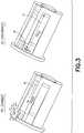
- Fig. 1illustrates the connection system of the present disclosure connecting the housing of an injector adapter to an intravenous line adapter according to an exemplary embodiment of the present disclosure.
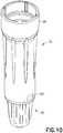
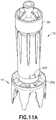
- Fig. 11Aillustrates the connection system of the present disclosure connecting the housing of an injector adapter to a vial adapter according to another exemplary embodiment of the present disclosure.
- the connection system of the present disclosuremay be used to connect other medical device components.
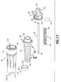
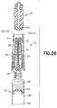
- injector adapter 12generally includes a cannula 20, a cannula seal 22, a spring 24, a needle hub 26, a cannula stabilizing member 28, a housing 29, a gliding ring 31, a one-way valve 232, and a filter 234.
- cannula 20includes a distal end 30, a proximal end 32, and a lumen 34 extending therebetween. Distal end 30 is in fluid communication with proximal end 32 via lumen 34 of cannula 20. As shown in Fig.
- distal end 30 of cannula 20is capable of piercing cannula seal 22 and a vial seal membrane 344 to place a vial chamber 96 in fluid communication with a barrel chamber 176 via cannula 20.
- distal end 30 of cannula 20defines a sharp point.
- Injector adapter 12is compatible with a system for the closed transfer of fluids that provides substantially leak-proof sealing and pressure balancing during engagement of a cannula with a vial, during transfer of a substance from a vial chamber to a barrel chamber via the cannula, and during disengagement of the cannula from the vial.
- a leak-proof sealing of the systemsubstantially prevents leakage of both air and liquid during use of the system.
- the systemis compatible with a needle and syringe assembly for accessing a medication contained within a vial for administering the medication to a patient.
- the systemis also compatible to be used with a drug reconstitution system.
- cannula seal 22generally includes a self-sealing seal secured over cannula 20 so that cannula seal 22 encloses cannula 20 in a sealed position ( Fig. 25 ) to provide a substantially leak-proof seal preventing any liquid, air, or medication residue from being exposed to a health care provider transferring, reconstituting, transporting, or administering a drug using injector adapter 12.
- Fig. 25with cannula seal 22 in the sealed position, cannula seal 22 encloses cannula 20 to also prevent accidental needle stick injuries to a user of injector adapter 12.
- Cannula seal 22includes a distal end 40, a proximal end 42, annular ribbed members 46 extending therebetween, and a shoulder portion 44 ( Fig. 16 ) located on an interior wall 48 near distal end 40 of cannula seal 22.
- distal end 40 of cannula seal 22includes an annular cavity 41.
- the distal end 40 of cannula seal 22defines a convex surface and has a transverse cross-sectional shape that is generally circular, although it is contemplated that other shapes and sizes of distal end 40 may be used.
- distal end 40 of cannula seal 22can have other multi-sided polygon cross-sectional shapes, such as square or oval cross-sectional shapes.
- the cannula seal 22may have a length that is about equal to a length of the cannula 20 and, upon assembly of the injector adapter 12, the cannula seal 22 may extend about the entire length of the cannula 20.
- cannula seal 22comprises a resilient material.
- cannula seal 22is preferably a unitary device molded of any flexible, elastomeric material conventionally used for fabricating gas-proof closures.
- Cannula seal 22may be formed of a natural rubber material, polyurethane elastomers, butyl rubbers, or similar materials. It is contemplated that cannula seal 22 is formed of a material having a Shore A hardness of approximately 10 to 50.
- cannula seal 22can have other material hardness values that would provide an appropriate self-sealing material to provide a substantially leak-proof seal with cannula seal 22 in the sealed position, thereby preventing any liquid or medication residue from being exposed to a health care provider transferring, reconstituting, transporting, or administering a drug using injector adapter 12.
- cannula seal 22comprises a resilient sleeve.
- spring 24includes a distal end 60 and a proximal end 62.
- Spring 24provides a biasing force that promotes cannula seal 22 to enclose cannula 20 in the sealed position as will be described in more detail below.
- spring 24is disposed over cannula 20 such that spring 24 is radially positioned between cannula 20 and cannula seal 22, i.e., cannula seal 22 encloses spring 24 and cannula 20.
- spring 24is disposed over cannula 20 and within cannula seal 22 such that distal end 60 of spring 24 engages shoulder portion 44 of cannula seal 22. In this manner, spring 24 exerts the biasing force on shoulder portion 44 of cannula seal 22. Shoulder portion 44 of cannula seal 22 also ensures that spring 24 is secured between shoulder portion 44 and needle hub 26.
- needle hub 26generally includes a distal end 50 and a proximal end 52.
- Proximal end 52 of needle hub 26includes a barrel connection portion 54.
- barrel connection portion 54is a female luer connector that is configured to mate with a male luer connector, although other suitable connectors may be utilized.
- the barrel connection portion 54includes a projection that is configured to be received by a corresponding threaded portion of the male luer connector. Other arrangements for the barrel connection portion 54 may be utilized that deter undesired disconnection from the needle hub 26.
- Needle hub 26supports and is secured to a portion of cannula 20.
- the needle hub 26is secured to the cannula 20 via an adhesive, such as an epoxy, although other suitable arrangements for securing the cannula 20 to the needle hub 26 may be utilized.
- Distal end 50 of needle hub 26also provides a connection with proximal end 62 of spring 24 so that distal end 60 of spring 24 may be compressed relative to proximal end 62 of spring 24 when cannula 20 pierces cannula seal 22 as will be described in more detail below. With spring 24 compressed, spring 24 exerts a biasing force that promotes cannula seal 22 to elastically enclose cannula 20. Referring to Fig.
- spring 24is loaded between shoulder portion 44 of cannula seal 22 and needle hub 26 in a slightly compressed position so that spring 24 exerts a biasing force that retains cannula seal 22 in the sealed position.
- annular ribbed members 46 of cannula seal 22provide an additional biasing force that retains cannula seal 22 in the sealed position.
- annular ribbed members 46 of cannula seal 22 and spring 24are compressed as cannula 20 pierces cannula seal 22 and vial adapter 14. With annular ribbed members 46 of cannula seal 22 compressed, annular ribbed members 46 exert an additional biasing force that promotes cannula seal 22 to elastically enclose cannula 20.
- housing 29generally includes a distal or first end 110, a proximal or second end 112, and a sidewall 114 extending therebetween.
- Sidewall 114 of housing 29defines a housing chamber 115.
- Housing chamber 115is sized and shaped to contain and house the components of injector adapter 12.
- the sidewall 114 of housing 29includes an exterior wall surface 116 and an interior wall surface 118.
- the interior wall surface 118 of the sidewall 114includes a connection element 120.
- connection element 120extends inwardly from interior wall surface 118 of sidewall 114 into housing chamber 115 adjacent distal end 110.
- connection element 120is engageable with a connection element of a vial adapter or an IV line adapter to secure injector adapter 12 to a vial adapter or an IV line adapter such that significant relative movement between injector adapter 12 and the vial adapter or IV line adapter is prevented.
- connection element 120comprises a first projecting member 121.
- first projecting member 121includes an elastically deformable tab for engagement with a connection element of a vial adapter or an IV line adapter as described in more detail below.
- housing 29also includes an elastically deformable portion for engagement with a connection element of a vial adapter or an IV line adapter as described in more detail below.
- the interior wall surface 118 of the sidewall 114includes a second connection element 122.
- second connection element 122extends inwardly from interior wall surface 118 of sidewall 114 into housing chamber 115 adjacent distal end 110.
- Second connection element 122is spaced a distance from first connection element 120.
- second connection element 122is spaced approximately 180 degrees (180°) from first connection element 120.
- Second connection element 122is engageable with a connection element of a vial adapter or an IV line adapter to secure injector adapter 12 to a vial adapter or an IV line adapter.
- second connection element 122comprises a second projecting member 123.
- second projecting member 123includes an elastically deformable tab for engagement with a connection element of a vial adapter or an IV line adapter as described in more detail below.
- the first and second connection elements 120, 122 of injector adapter 12form a first portion of a connection system of the present disclosure which is compatible with connection elements of a vial adapter or an IV line adapter which form a second portion of a connection system of the present disclosure as discussed in more detail below.
- first and second connection elements 120, 122 of injector adapter 12a material that is capable of elastic flexing without cracking is used to form first and second connection elements 120, 122 of injector adapter 12.
- flexible polymersmay be used to form first and second connection elements 120, 122 of injector adapter 12.
- flexible polymerssuch as polyolefines may be used, e.g., polypropylene, polyethylene, and their co-polymers.
- Housing 29provides a protective housing which seals the components of injector adapter 12 within housing 29, i.e., housing 29 provides a leak prevention and protection enclosure, protects the components of injector adapter 12 contained within housing 29, and/or maintains a sealed, sterilized environment within housing 29.
- Housing 29also provides connection elements 120, 122 which provide for engagement with a connection element of a vial adapter or an IV line adapter to secure injector adapter 12 to a vial adapter or an IV line adapter.
- housing 29also includes an elastically deformable portion for engagement with a connection element of a vial adapter or an IV line adapter as described in more detail below.
- injector adapter 12includes cannula stabilizing member 28.
- Cannula stabilizing member 28includes a distal end 70, a proximal end 72, and an annular ring 74 therebetween.
- cannula stabilizing member 28is disposed within cannula seal 22 such that annular ring 74 of cannula stabilizing member 28 engages shoulder portion 44 of cannula seal 22. In this position, cannula stabilizing member 28 supports a portion of cannula 20 and provides stability to cannula 20 during engagement of cannula 20 with a vial or other device.
- spring 24is disposed over cannula 20 and within cannula seal 22 such that distal end 60 of spring 24 engages annular ring 74 of cannula stabilizing member 28. In this manner, spring 24 exerts the biasing force on annular ring 74 of cannula stabilizing member 28 which exerts the biasing force on shoulder portion 44 of cannula seal 22.
- injector adapter 12includes gliding ring 31.
- Gliding ring 31includes an exterior wall surface, i.e., a gliding surface 252 and an interior surface 254.
- the interior surface 254 of gliding ring 31includes an annular protrusion 256.
- the annular protrusion 256extends radially inwards from interior surface 254.
- gliding ring 31is disposed within housing 29 such that annular protrusion 256 is received within annular cavity 41 of cannula seal 22 to secure the gliding ring 31 to the cannula seal 22 such that the gliding ring 31 is positioned between cannula seal 22 and interior wall surface 118 of housing 29.
- gliding ring 31supports a portion of cannula seal 22 and provides stability to cannula seal 22 within housing 29 during engagement of cannula 20 with a vial or other device.
- Gliding ring 31also provides stability to cannula seal 22 with cannula seal 22 moving within housing 29.
- injector adapter 12is configured to provide an aspiration arrangement 230 to allow air to enter the injector adapter 12 for aspirating air into a syringe barrel while using seal and pressure equalization system 10.
- the aspiration arrangement 230allows a user to aspirate air into the barrel chamber 176 after injector adapter 12 is secured to the barrel assembly 16.
- the aspiration arrangement 230includes a one-way valve 232 and filter 234.
- the needle hub 26includes an inner wall 236 and an outer wall 238 that defines an annular recess 240.
- the needle hub 26further defines at least one passageway 242 that extends perpendicularly to a longitudinal axis of the hub 26.
- the passageway 242extends through the inner wall 236.
- the outer wall 238defines a cutout 243 that is configured to receive the filter 234.
- the cutout 243is in fluid communication with the passageway 242 and the annular recess 240.
- the filter 234is a flat filter sheet positioned within the cutout 243, although other suitable arrangements may be utilized.
- the filter 234may be ring-shaped and fitted within the annular recess 240 rather than being positioned within the cutout 243.
- the filter 234may be any suitable commercially available filter, such as a particulate air filter having a pore size of 0.2 ⁇ m or larger.
- the filter 234may be configured remove viable micro-organisms.
- the one-way valve 232is embodied as an extension 244 of the cannula seal 22 that extends into the needle hub 26.
- the extension 244is formed integrally with the cannula seal 22, although the extension 244 may be formed separately.
- the extension 244 of the cannula seal 22abuts and extends along at least a portion of an inner surface 246 of the inner wall 236.
- the extension 244is configured to selectively allow the flow of outside air through the passageway 242 and the filter 234 and into the cannula seal 22.
- the extension 244in response to a pressure drop within the cannula seal 22 caused by aspiration, the extension 244 will deflect inwardly to open the passageway 242 and allow outside air to be drawn into the barrel chamber 176 of barrel assembly 16. After aspiration, the extension 244 will return to its original position to block or close the passageways 242. When the cannula seal 22 is under a positive pressure, the extension 244 is forced radially outward and continues to block and seal the passageway 242. Air may first be injected into the vial chamber 96 of vial 90 prior to withdrawing fluid, such as substance 98, from the vial chamber 96.
- fluidsuch as substance 98
- the one-way valve 232 and filter 234allows a user to aspirate air into the barrel chamber 176 after the injector adapter 12 is secured to the barrel assembly 16. Furthermore, the filter 234 is configured to filter the outside air that is aspirated into the barrel assembly 16, which advantageously allows clean filter air to be injected into the vial chamber 96.
- proximal end 52 of needle hub 26is attached to a barrel 160 of barrel assembly 16.
- needle hub 26With needle hub 26 supporting a portion of cannula 20 and with proximal end 52 of needle hub 26 attached to barrel 160 of barrel assembly 16, needle hub 26 attaches cannula 20 to barrel assembly 16 such that cannula 20 is in fluid communication with barrel chamber 176 of barrel 160.
- barrel assembly 16includes barrel 160, a plunger rod 162, and a stopper 164.
- Barrel assembly 16may be adapted for the dispensing and delivery of a fluid and/or collection of a fluid.
- barrel assembly 16may be used for injection or infusion of fluid such as a medication into a patient.
- Barrel assembly 16is contemplated for use in connection with a needle, such as by connecting barrel assembly 16 to cannula 20 as described, connecting barrel assembly 16 to a separate needle assembly (not shown), or alternatively, for connection with an intravenous (IV) connection assembly such as IV line adapter 18.
- IVintravenous
- syringe assemblyincluding, but not limited to, metered dose syringes, aspiration syringes for withdrawing fluid from a patient or medication from a container or vial, and the like.
- IV line adapter 18includes first end 130 and opposing second end 131. IV line adapter 18 provides a compact and accessible connector for connecting a cartridge or barrel containing a reconstituted drug to an intravenous line or an injection apparatus for administering the drug to a patient.
- First end 130 of IV line adapter 18includes a connection system 132.
- Connection system 132 of IV line adapter 18forms a portion of a connection system of the present disclosure which is compatible with a connection system 120, 122 of injector adapter 12 which form another portion of a connection system of the present disclosure as discussed in more detail below.
- connection system 132includes a first connection element 133 disposed at first end 130 of IV line adapter 18 which is engageable with a connection element 120, 122 of an injector adapter 12 to secure the injector adapter 12 to IV line adapter 18.
- first end 130 of IV line adapter 18includes a second connection element 134.
- Second connection element 134is spaced a distance from first connection element 133.
- second connection element 134is spaced approximately 180 degrees (180°) from first connection element 133.
- Second connection element 134is engageable with a connection element 120, 122 of an injector adapter 12 to secure the injector adapter 12 to IV line adapter 18 such that significant relative movement between injector adapter 12 and IV line adapter 18 is prevented.
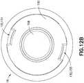
- first connection element 133 of connection system 132includes a first connection path 136, a first disconnection path 138, and a first securement element 140 disposed between the first connection path 136 and first disconnection path 138.
- first connection path 136, first disconnection path 138, and first securement element 140together generally define a U-shaped path.
- First connection path 136is distinct from first disconnection path 138. In this manner, the distinct connection and disconnection paths allow for the fine tuning of tactile and audible responses separately for connection and disconnection movements.
- divider wall 139is disposed between first connection path 136 and first disconnection path 138.
- first connection element 133 of IV line adapter 18may be used for first connection element 133 of IV line adapter 18.
- first connection element 133 of IV line adapter 18is made from a rigid material such as a hard plastic, metal, or ceramic material. The important characteristics of the materials used to make first connection element 133 of IV line adapter 18 is that they are a more rigid material than the materials used to form connection element 120 of injector adapter 12.
- first connection path 136comprises a first connection channel.
- first disconnection path 138comprises a first disconnection channel.
- first securement element 140comprises a locking recess.
- First connection path 136includes a connection guide surface 141, a first connection guide wall 142, and a second connection guide wall 143 which together form a channel that guides connection element 120 of injector adapter 12 to enter engagement with IV line adapter 18 as described in more detail below.
- Connection guide surface 141includes an entry portion 144 and an exit portion 145 adjacent securement element 140.
- guide surface 141tapers upwards from entry portion 144 to exit portion 145. In this manner, guide surface 141 receives, guides, and deforms connection element 120 of injector adapter 12 as described in more detail below.
- First connection path 136includes a step member 135 disposed between first securement element 140 and first disconnection path 138.
- Step member 135includes an exit recess step 147, an enter disconnection path step 148, and a top step surface 149 disposed therebetween.
- Step member 135provides a component that allows connection element 120 of injector adapter to be rotated out from engagement with securement element 140. Also, step member 135 can be used to tune resistance and provide tactile feel during a disconnection movement as described in more detail below.
- First disconnection path 138includes a disconnection guide surface 150, a first disconnection guide wall 151, and a second disconnection guide wall 152 which together form a channel that guides connection element 120 of injector adapter 12 to exit IV line adapter 18 as described in more detail below.
- Disconnection guide surface 150includes an entry portion 153 adjacent step member 135 and an exit portion 154 that includes a barrier exit wall 155.
- guide surface 150tapers upwards from entry portion 153 to exit portion 154. In this manner, guide surface 150 receives, guides, and deforms connection element 120 of injector adapter 12 as described in more detail below.
- second connection element 134 of connection system 132includes a second connection path 170, a second disconnection path 171, and a second securement element 172 disposed between the second connection path 170 and second disconnection path 171.
- second connection path 170, second disconnection path 171, and second securement element 172together generally define a U-shaped path.
- Second connection path 170is distinct from second disconnection path 171. In this manner, the distinct connection and disconnection paths allow for the fine tuning of tactile and audible responses separately for connection and disconnection movements.
- divider wall 174is disposed between second connection path 170 and second disconnection path 171.
- second connection element 134 of IV line adapter 18may be used for second connection element 134 of IV line adapter 18.
- a wide variety of thermoplastic and thermosetting polymers and similar materialsmay be used to form second connection element 134 of IV line adapter 18.
- second connection element 134 of IV line adapter 18is made from a rigid material such as a hard plastic, metal, or ceramic material. The important characteristics of the materials used to make second connection element 134 of IV line adapter 18 is that they are a more rigid material than the materials used to form second connection element 122 of injector adapter 12.
- second connection path 170comprises a second connection channel.
- second disconnection path 171comprises a second disconnection channel.
- second securement element 172comprises a locking recess.
- Second connection path 170includes a connection guide surface 180, a first connection guide wall 181, and a second connection guide wall 182 which together form a channel that guides second connection element 122 of injector adapter 12 to enter engagement with IV line adapter 18 as described in more detail below.
- Connection guide surface 180includes an entry portion 183 and an exit portion 184 adjacent securement element 172.
- guide surface 180tapers upwards from entry portion 183 to exit portion 184. In this manner, guide surface 180 receives, guides, and deforms second connection element 122 of injector adapter 12 as described in more detail below.
- Second connection path 170includes a step member 173 disposed between second securement element 172 and second disconnection path 171.
- Step member 173includes an exit recess step 191, an enter disconnection path step 192, and a top step surface 193 disposed therebetween.
- Step member 173provides a component that allows second connection element 122 of injector adapter 12 to be rotated out from engagement with securement element 172. Also, step member 173 can be used to tune resistance and provide tactile feel during a disconnection movement as described in more detail below.
- Second disconnection path 171includes a disconnection guide surface 185, a first disconnection guide wall 186, and a second disconnection guide wall 187 which together form a channel that guides second connection element 122 of injector adapter 12 to exit IV line adapter 18 as described in more detail below.
- Disconnection guide surface 185includes an entry portion 188 adjacent step member 173 and an exit portion 189 that includes a barrier exit wall 190.
- guide surface 185tapers upwards from entry portion 188 to exit portion 189. In this manner, guide surface 185 receives, guides, and deforms second connection element 122 of injector adapter 12 as described in more detail below.
- First end 130 of IV line adapter 18includes a pierceable barrier membrane 158.
- the pierceable barrier membrane 158provides for a liquid and gas tight seal between a piercing member of a barrel assembly and the pierceable barrier membrane 158 during fluid transfer of a medication to a patient so to minimize leakage and thereby prevent exposure of hazardous medicaments to a user.
- Barrier membrane 158provides a self-sealing seal that, with a barrel assembly attached to IV line adapter 18, provides a leak-proof seal preventing any substance being administered to a patient from being exposed to a health care provider administering the medication.
- barrier membrane 158comprises a resilient material.
- barrier membrane 158is preferably a unitary device molded of any flexible, elastomeric material conventionally used for fabricating gas-proof closures.
- Barrier membrane 158may be formed of a natural rubber material, polyurethane elastomers, butyl rubbers, or similar materials.
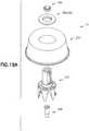
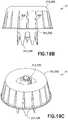
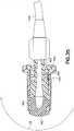
- vial adapter 14includes a vial access system 312 and a pressure equalization system 314.
- Vial adapter 14is configured to establish fluid communication between a first container and a second container.
- vial adapter 14is attachable to a vial 90.
- vial 90may be a standard drug vial of any type having an open head portion 93 covered by a pierceable septum 94 of an elastomeric material. Walls 95 of vial 90 define vial chamber 96 for containing a substance 98. Vial septum 94 is engaged with head portion 93 of vial 90 to seal the substance 98 within vial chamber 96.
- Vial adapter 14is compatible with a system for the closed transfer of fluids that provides substantially leak-proof sealing and pressure balancing during engagement of a cannula with a vial, during transfer of a substance from a vial chamber to a barrel chamber via the cannula, and during disengagement of the cannula from the vial.
- vial adapter 14With pressure equalization system 314 secured to vial access system 312, vial adapter 14 includes first end 302, opposing second end 303, and wall 304 extending between first end 302 and second end 303. Wall 304 defines an exterior profile 306 as will be described in more detail below.
- vial adapter 14With vial adapter 14 attached to a vial 90, the vial adapter 14 provides a leak-proof seal and pressure equalization system that prevents any substance contained within a chamber of the vial from being exposed to a health care provider reconstituting, transporting, or administering a drug.
- vial adapter 14 and the packaging memberprovides a secure fit therebetween, such that, with vial adapter 14 received within the packaging member, the packaging member can be used as an interface between the hand of a user and vial adapter 14 so that vial adapter 14 can be placed onto a vial without taking vial adapter 14 out of the packaging member.
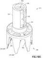
- vial access system 312 of vial adapter 14includes vial access housing 330 having first end 332 and opposing second end 334.
- First end 332 of vial access housing 330includes a connection element or connection system 336.
- First connection element 336is engageable with a connection element 120, 122 of an injector adapter 12 to secure the injector adapter 12 to vial adapter 14.
- first end 332 of vial access housing 330includes a second connection element or second connection system 339.
- Second connection element 339is spaced a distance from first connection element 336.
- second connection element 339is spaced approximately 180 degrees (180°) from first connection element 336.
- Second connection element 339is engageable with a connection element 120, 122 of an injector adapter 12 to secure the injector adapter 12 to vial adapter 14 such that significant relative movement between injector adapter 12 and vial adapter 14 is prevented.
- first and second connection elements 336, 339 of vial adapter 14form a second portion of a connection system of the present disclosure which is compatible with connection elements of an injector adapter which form a first portion of a connection system of the present disclosure as discussed in more detail below.
- Figs. 19A-19Gillustrate another exemplary embodiment of the present disclosure.
- the connection system of first and second connection elements 336, 339 of vial adapter 14 illustrated in Figs. 19A-19Ginclude similar components to the connection system of first connection element 133 and second connection element 134 of IV line adapter 18 illustrated in Figs. 12-14B , and the similar components are denoted by a reference number followed by the letter A.
- these similar components and the similar steps of using the connection system of first and second connection elements 336, 339 of vial adapter 14will not all be discussed in conjunction with the embodiment illustrated in Figs. 19A-19G .
- First end 332 of vial access housing 330is substantially formed by a neck portion 333.
- neck portion 333may include a guiding groove arranged therein to guide corresponding guiding protrusions on a cannula adapter or syringe assembly, for example, to establish a secure attachment between the cannula adapter or syringe assembly and vial adapter 14 after which fluid communication can be established.
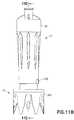
- a vial connection member or vial engagement member 337is disposed at second end 334 of vial access housing 330.
- vial connection member 337includes a plurality of vial grip members 338 that are disposed at second end 334 of vial access housing 330.
- Vial grip members 338are attachable to a vial 90 to secure vial adapter 14 to the vial 90.
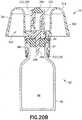
- Each vial grip member 338includes a hook protrusion 340 arranged to engage a corresponding flange on a container such as a vial 90 as shown in Figs. 20A and 20B .
- Vial connection member 337 of vial access housing 330may be dimensioned to be attached to containers of any size and volume.
- vial connection member 337 of vial access housing 330may include other connection mechanisms for securing vial adapter 14 to vial 90 such as a threaded portion, a snap fit mechanism, locking tabs, or other similar mechanism.
- a fluid transfer channel 342extends substantially between first end 332 and second end 334 of vial access housing 330.
- the purpose of fluid transfer channel 342is to permit a needle cannula to extend through vial access housing 330 of vial adapter 14 and to thereby permit fluid to be transferred through vial adapter 14.
- a pierceable barrier member or vial seal membrane 344is arranged in the fluid transfer channel 342 at first end 332 of vial access housing 330.
- the pierceable barrier member 344provides for a liquid and gas tight seal between a piercing member and the pierceable barrier member 344 during fluid transfer so to minimize leakage and thereby prevent exposure of hazardous medicaments to a user.
- Vial seal membrane 344provides a self-sealing seal that, with vial adapter 14 attached to vial 90 such that vial seal membrane 344 is aligned with vial septum 94, provides a leak-proof seal preventing any substance contained within vial chamber 96 from being exposed to a health care provider reconstituting, transporting, or administering a drug using system 10.
- vial seal membrane 344, vial sleeve seal 350, and cannula seal 22provide a leak-proof seal that is liquid tight and airtight preventing any substance residue from being exposed to a health care provider while reconstituting or withdrawing substance 98 from vial 90 to barrel 160 via cannula 20.
- vial seal membrane 344comprises a resilient material.
- vial seal membrane 344is preferably a unitary device molded of any flexible, elastomeric material conventionally used for fabricating gas-proof closures.
- Vial seal membrane 344may be formed of a natural rubber material, polyurethane elastomers, butyl rubbers, or similar materials. It is contemplated that vial seal membrane 344 is formed of a material having a Shore A hardness of approximately 10 to 50.
- vial seal membrane 344can have other material hardness values that would provide an appropriate self-sealing material to provide a leak-proof seal with vial septum 94 of vial 90 and cannula seal 22, thereby preventing any liquid or medication residue from being exposed to a health care provider reconstituting, transporting, or administering a drug using system 10.
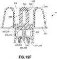
- a piercing member or spike member 346Protruding out from vial access housing 330 at second end 334 is a piercing member or spike member 346 which includes piercing tip 348.
- fluid transfer channel 342extends inside of spike member 346.
- the spike member 346extends in a direction substantially parallel with the plurality of vial grip members 338 and serves the purpose of piercing a fluid container such as a vial 90 during assembly of vial adapter 14 to a vial 90 as is shown in greater detail in Fig. 20B .
- a vial sleeve seal 350is disposed over the spike member 346.
- the vial sleeve seal 350provides a seal between vial adapter 14 and a vial 90 with the piercing tip 348 of spike member 346 engaged with the vial 90.
- vial sleeve seal 350comprises a rubber spike sleeve.
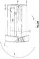
- pressure equalization system 314includes pressure equalization housing 360 and toroidal expandable balloon 362 which includes an expansion chamber 366.
- Pressure equalization housing 360defines a tapered exterior wall portion 361 and an interior annular ring cavity portion 363.
- tapered exterior wall portion 361includes a plurality of stabilizing ribs 365.
- stabilizing ribs 365may extend in an axial direction along tapered exterior wall portion 361 of pressure equalization housing 360 and the ribs 365 may be spaced around a periphery of pressure equalization housing 360.
- Expandable balloon 362includes a variable volume.
- Pressure equalization housing 360comprises a relatively rigid material and expandable balloon 362 comprises a relatively flexible material.
- expandable balloon 362comprises a thin, transparent plastic film that is attached to pressure equalization housing 360 in a gastight manner.
- expandable balloon 362is designed as a bellow which is compressible and extendable and thus the volume of the expansion chamber 366 of expandable balloon 362 can thereby be increased and decreased.
- interior annular ring cavity portion 363 of pressure equalization housing 360extends radially around vial access housing 330 and expandable balloon 362 extends radially around vial access housing 330.
- Pressure equalization housing 360provides a barrier wall member that protects expandable balloon 362 from being torn during engagement of a cannula with a vial, during transfer of a substance from a vial chamber to a barrel chamber via the cannula, and during disengagement of the cannula from the vial.
- the vial adapter 14is balanced such that a center of mass is positioned at about a longitudinal axis of vial adapter 14.
- expandable balloon 362extends 360 degrees (360°) radially around vial access housing 330.
- a portion of toroidal expandable balloon 362is not covered by pressure equalization housing 60. In this manner, expandable balloon 362 is capable of expanding in an axial direction.
- pressure equalization housing 360 and vial access housing 330are a single integral component. In another embodiment, pressure equalization housing 360 and vial access housing 330 are separate components and pressure equalization housing 360 is attachable to vial access housing 330 such that significant relative movement between pressure equalization housing 360 and vial access housing 330 is prevented.
- a pressure normalization channel 370extends from second end 334 of vial access housing 330 to exit aperture 364 of pressure equalization housing 360.
- Pressure normalization channel 370is arranged to provide gas communication between the expandable balloon 362 and the interior of a vial 90 when the vial adapter 14 is connected to a vial 90.
- a syringe or cannula assemblymay be used to inject fluid into the vial 90 or to withdraw fluid therefrom as described in more detail below.
- pressure normalization channel 370extends from a portion of piercing tip 348 of spike member 346 and substantially parallel with fluid transfer channel 342 inside spike member 346.
- the pressure normalization channel 370diverts in a direction perpendicular to fluid transfer channel 342 substantially at shoulder portion 372 of pressure normalization channel 370.
- the pressure normalization channel 370includes an inlet opening 374 arranged substantially at a portion of piercing tip 348 of spike member 346 and an outlet opening 376 positioned substantially at exit aperture 364 of pressure equalization housing 360.
- the pressure normalization channel 370comprises a filter 380 arranged to cover a region of the pressure normalization channel 370.
- the filter 380serves the purpose of preventing any fluid from a container, such as a vial, from reaching expansion chamber 366 of expandable balloon 362.
- the filter 380is preferably a hydrophobic filter which permits gas to pass, but prevents liquid to pass.
- the filter 380may be secured within pressure equalization housing 360 via filter holder 382.
- vial adapter 14may also include a valve arrangement positioned in the proximity of outlet opening 376 of the pressure normalization channel 370.
- a valve arrangementprevents clogging of the filter 380 by providing a cracking pressure to the valve arrangement for the fluid which flows in a direction from the inlet opening 374 to the outlet opening 376 of the pressure normalization channel 370 while permitting preferably a minimal cracking pressure in the opposite direction.
- vial adapter 14When preparing and administering drugs, care has be taken to minimize, or preferably eliminate, the risk of exposing people, such as medical and pharmacological personnel, to toxic substances. Some drugs must be dissolved or diluted before they are administered, which involves transferring a solvent from one container to a sealed vial containing the drug in powder or liquid form, by means of a needle, for example. Drugs may be inadvertently released into the atmosphere in gas form or by way of aerosolization, during the withdrawal of the needle from the vial, and while the needle is inside the vial, if any pressure differential between the interior of the vial and surrounding atmosphere exists.
- Vial adapter 14 of the present disclosureeliminates this problem by using pressure equalization system 314 of vial adapter 14 that may be attached to a vial during the preparation of drugs.
- the pressure equalization system 314includes an expandable balloon 362 which in communication with the interior of the vial 90 ensures that neither an increased pressure nor a vacuum can occur inside the vial 90 when gas or liquid is injected into or withdrawn from the vial 90.
- the expandable balloon 362may be filled with cleaned or sterilized air prior to its use to ensure that the contents of the vial 90 do not become contaminated with air-borne particles such as dust, pollen, mold or bacteria, or other undesirable substances.
- the vial adapter 14is assembled via its connection element 336 of vial access housing 330 to a cannula 20 of injector adapter 12 which in turn can be connected to a fluid container, such as barrel assembly 16, and the vial adapter 14 is also assembled via its vial connection members 337 with a second fluid container, such as a vial 90.
- a vial 90As vial adapter 14 is assembled with the vial 90, the piercing tip 348 of the spike member 346 is pierced through a septum 94 of the vial 90.
- Vial 90may be a standard drug vial of any type having an open head portion covered by a pierceable septum of an elastomeric material.
- the walls 95 of vial 90define a vial chamber 96 for containing a substance 98.
- the vial septum 94is engaged with the head portion 93 of vial 90 to seal a substance within vial chamber 96.
- the plurality of vial grip members 338fixedly connect vial adapter 14 to the vial 90 as the hook protrusions 340 of vial grip members 338 engage the corresponding flange 97 on vial 90 as shown in Fig. 20B . After assembly, a user is able to insert fluid into the vial 90, or optionally to retract fluid from the vial 90.
- pressure equalization system 314 of vial adapter 14permits pressure equalization between the vial 90 and the expandable balloon 362.
- the pressure normalization channel 370normalizes the pressure inside the vial 90 by relieving the pressure inside the vial 90 to the expansion chamber 366 of the expandable balloon 362 as shown in Figs. 21A-21C .
- Figs. 22-25 and 21A-21Cshow the vial adapter 14 attached to the vial 90 and with cannula 20 inserted through the vial adapter 14 and into the interior of the vial 90.
- the pressure normalization channel 370 of the pressure equalization system 314 of vial adapter 14permits gas to flow from the interior of the vial 90 into the expandable balloon 362 or from the expansion chamber 366 of the expandable balloon 362 to the vial 90, and thereby equalizes the pressure in the interior of the vial 90. Gas may enter the expandable balloon 362 via outlet opening 376, however gas cannot exit from the expandable balloon 362.
- connection system of the present disclosureto connect a first medical device component, e.g., injector adapter 12, to a second medical device component, e.g., IV line adapter 18, will now be described.
- first connection element 120 of injector adapter 12is aligned with the first connection path 136 of IV line adapter 18 and the second connection element 122 of injector adapter 12 is aligned with the second connection path 170 of IV line adapter 18 as shown in Figs. 1 , 2 , and 9A .
- a usercan push injector adapter 12 and IV line adapter 18 together so that first connection element 120 of injector adapter 12 enters first connection path 136 of IV line adapter 18 and second connection element 122 of injector adapter 12 enters second connection path 170 of IV line adapter 18.
- the path that connection elements 120, 122 of injector adapter 12 follow, through respective connection paths 136, 170 of IV line adapter 18,is shown in the connection illustration of Fig.
- connection elements 120, 122 of injector adapter 12are guided through respective connection paths 136, 170 of IV line adapter 18 from respective entry portions 144, 183 to respective exit portions 145, 184 in a direction generally along arrow A ( Fig. 3 ).
- connection elements 120, 122are compressed via the upwardly tapering guide surface 141, 180.
- connection elements 120, 122are elastically deformed such that connection elements 120, 122 snap into respective locking recesses or securement elements 140, 172 as shown in Figs. 5A-5C .
- connection elements 120, 122are elastically deformed such that connection elements 120, 122 snap into respective locking recesses or securement elements 140, 172, connection elements 120, 122 make an audible snapping or clicking sound that enables a user to be informed that a secure connection has been made.
- connection elements 120, 122slide over and past respective exit portions 145, 184 of tapered guide surfaces 141, 180, elastic connection elements 120, 122 snap back or return to their undeformed position and lock within respective securement elements 140, 172, i.e., with connection elements 120, 122 mechanically locked within respective securement elements 140, 172, injector adapter 12 is connected to IV line adapter 18, such that, significant relative movement between injector adapter 12 and IV line adapter 18 is prevented.
- the locked position of Fig. 4illustrates the elastically deformable connection elements 120, 122 of injector adapter 12 in a locked position in which connection elements 120, 122 are in their undeformed position and are locked within respective securement elements 140, 172.
- the unlocked position of Fig. 4illustrates the elastically deformable connection elements 120, 122 of injector adapter 12 in a deformed position in which connection elements 120, 122 are deformed as they travel through the respective upwardly tapering guide surfaces 141, 180 of IV line adapter 18.
- connection elements 120, 122 of injector adapter 12can be rotated in a counter-clockwise direction generally along arrow B to rotate connection elements 120, 122 out of engagement with respective securement elements 140, 172.
- Step members 135, 173provide a component that allows connection elements 120, 122 of injector adapter 12 to be rotated out from engagement with respective securement elements 140, 172.
- connection elements 120, 122For example, as a rotational force is exerted on connection elements 120, 122 to move connection elements 120, 122 in a direction generally along arrow B to move connection elements 120, 122 out of securement elements 140, 172, connection elements 120, 122 cooperate with a respective tapered exit recess step 147, 191 of IV line adapter 18.
- the respective tapered exit recess steps 147, 191 of IV line adapter 18provide a ramp surface to deform respective connection elements 120, 122 outwardly until connection elements 120, 122 advance beyond, i.e., slide over and past, respective top step surfaces 149, 193 of step members 135, 173 as shown in Figs. 6A-6C .
- connection elements 120, 122slide over and past respective top step surfaces 149, 193 of step members 135, 173, connection elements 120, 122 snap into respective entry portions 153, 188 of disconnection paths 138, 171.
- connection elements 120, 122are elastically deformed such that connection elements 120, 122 snap into respective entry portions 153, 188 of disconnection paths 138, 171, connection elements 120, 122 make an audible snapping or clicking sound that enables a user to be informed that a disconnection has been made.
- connection elements 120, 122snap into respective entry portions 153, 188 of disconnection paths 138, 171, connection elements 120, 122 return to their undeformed or original position within respective entry portions 153, 188 of disconnection paths 138, 171.
- step members 135, 173can be used to tune resistance and provide tactile feel during a disconnection movement.
- connection elements 120, 122With connection elements 120, 122 in respective disconnection paths 138, 171 of IV line adapter 18, a pulling force may be exerted in a direction generally along arrow C ( Fig. 3 ) to pull injector adapter 12 out from IV line adapter 18.
- connection elements 120, 122 of injector adapter 12are guided through respective disconnection paths 138, 171 of IV line adapter 18 from respective entry portions 153, 188 to respective exit portions 154, 189 in a direction generally along arrow C ( Fig. 3 ), connection elements 120, 122 are compressed via the upwardly tapering guide surfaces 150, 185.
- barrier exit walls 155, 190provide a physical barrier to prevent respective connection elements 120, 122 from being easily removed from disconnection paths 138, 171. Once a force is exerted to deform connection elements 120, 122 so they slide over and past respective barrier exit walls 155, 190, connection elements 120, 122 return to their undeformed or original position past barrier exit walls 155, 190 and injector adapter 12 is removed from IV line adapter 18 as shown in Fig. 1 .
- connection system of the present disclosureprovides for quick and intuitive coupling and decoupling of two opposing medical device components through the use of a connection path and a disconnection path, the connection path being distinct from the disconnection path. Furthermore, the connection system of the present disclosure provides audible and tactile connection feedback through the use of elastically deformable connection elements.
- Figs. 11A-11Cillustrate the use of a connection system of the present disclosure to connect injector adapter 12 to vial adapter 14.
- the connection system of first and second connection elements 336, 339 of vial adapter 14, illustrated in Figs. 19A-19Ginclude similar components to the connection system of first connection element 133 and second connection element 134 of IV line adapter 18 illustrated in Figs. 12-14B , and the similar components are denoted by a reference number followed by the letter A.
- the similar steps of the use of a connection system of the present disclosure to connect injector adapter 12 to vial adapter 14will not be described in detail as the steps are the same as described above to connect injector adapter 12 to IV line adapter 18.
- Fig. 27illustrates a further exemplary embodiment of an IV line adapter 18B and an injector adapter 12B.
- injector adapter 12Bincludes slits 68B on opposing sides of connection elements 120B, 122B.
- Figs. 28-35illustrate another exemplary embodiment.
- the embodiment illustrated in Figs. 28-35includes similar components to the embodiment illustrated in Figs. 1-26 , and the similar components are denoted by a reference number followed by the letter A.
- connection system 132AFigs. 28-35
- connection system 132AFigs. 28-35
- connection system 132Aincludes a connector 400, a membrane 402, and a first luer component 404 which are compatible with a second luer component 406 and an IV line 408 as will be discussed in more detail below.
- connector 400includes first end 410, opposing second end 412, and annular protrusion 414.
- connector 400comprises an IV line adapter connector component.
- Connector 400provides a compact and accessible connector for connecting a cartridge or barrel containing a reconstituted drug to an intravenous line or an injection apparatus for administering a drug to a patient.
- First end 410 of connector 400includes a first connection element 133A of connection system 132A.
- First connection element 133A of connector 400forms a portion of a connection system of the present disclosure which is compatible with a connection system 120, 122 of injector adapter 12 which forms another portion of a connection system of the present disclosure as discussed above.
- first connection element 133A of connector 400includes a first connection path 136A, a first disconnection path 138A, and a first securement element 140A disposed between the first connection path 136A and first disconnection path 138A.
- first connection path 136A, first disconnection path 138A, and first securement element 140Atogether generally define a U-shaped path.
- First connection path 136Ais distinct from first disconnection path 138A. In this manner, the distinct connection and disconnection paths allow for the fine tuning of tactile and audible responses separately for connection and disconnection movements as described in detail above.
- divider wall 139Ais disposed between first connection path 136A and first disconnection path 138A. Referring to Fig.
- connection system 132A of connector 400includes first disconnection path 138A that is located on an opposite side of first connection path 136A relative to the embodiment illustrated in Fig. 2 .
- connection system 132A of connector 400requires an injector, such as injector adapter 12, to be rotated in a clockwise direction to disconnect the injector from connector 400.
- injectorsuch as injector adapter 12
- an overall connector tightening to an IV lineresults during the use of connection system 132A as will be described in more detail below.
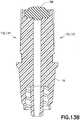
- system 132Aincludes a pierceable barrier membrane 402.
- Membrane 402includes a first end 430, opposing second end 432, and an annular groove 434.
- membrane 402is attachable to first end 410 of connector 400 by a press fit or interference fit.
- membrane 402is attached to connector 400 by pressing membrane 402 within first end 410 of connector 400 such that annular protrusion 414 of connector engages annular groove 434 of membrane 402 to secure membrane 402 to connector 400 as shown in Fig. 29 .
- the assembly of the membrane 402 within a corresponding connectoris described in more detail below.
- the first end 430 of the membrane 402defines a convex surface, although other suitable shaped surfaces may be utilized.
- the second end 432 of the membrane 402defines a cavity 403 that extends toward the first end 430 of the membrane 402.
- the cavity 403terminates between the first end 430 and second end 432 of the membrane at about half a length of the membrane 402.
- the terminal end of the cavity 403may define a concave surface, although other suitable shaped surfaces may be utilized.
- the cavity 403tapers and narrows as it extends toward the first end 430 of the membrane 402.
- the second end 432 of the membrane 402includes an annular projection 405 extending away from the second end 432 of the membrane 402.
- the pierceable barrier membrane 402provides for a liquid and gas tight seal between a piercing member of a barrel assembly and the pierceable barrier membrane 402 during fluid transfer of a medication to a patient so to minimize leakage and thereby prevent exposure of hazardous medicaments to a user.
- Barrier membrane 402provides a self-sealing seal that, with a barrel assembly attached to connector 400, provides a leak-proof seal preventing any substance being administered to a patient from being exposed to a health care provider administering the medication.
- barrier membrane 402comprises a resilient material.
- barrier membrane 402is preferably a unitary device molded of any flexible, elastomeric material conventionally used for fabricating gas-proof closures.
- Barrier membrane 402may be formed of a natural rubber material, polyurethane elastomers, butyl rubbers, or similar materials.
- system 132Aincludes a male or first luer component 404.
- First luer component 404includes first end 440, opposing second end 442, threaded portion 444, and membrane receiving portion 446.
- a female or second luer component 406is attached to an end of IV line 408.
- the threaded portion 444 of first luer component 404is engageable with a threaded portion 460 ( Fig. 35 ) of second luer component 406 to secure first luer component 404 to second luer component 406 and IV line 408 as shown in Fig. 35 .
- First luer component 404is rotated in a clockwise direction generally along arrow CW ( Fig. 35 ) relative to second luer component 406 to tighten and secure threaded portion 444 of first luer component 404 to threaded portion 460 of second luer component 406.
- first luer component 404is attachable to second end 412 of connector 400 by a press fit or interference fit.
- first luer component 404is attached to connector 400 by pressing first luer component 404 within second end 412 of connector 400 such that second end 432 of membrane 402 engages membrane receiving portion 446 of first luer component 404 to secure first luer component 404, membrane 402, and connector 400 theretogether as shown in Fig. 29 .
- connection system 132A of the present disclosureto connect a first medical device component, e.g., injector adapter 12, to a second medical device component, e.g., connector 400, will now be described.
- first medical device componente.g., injector adapter 12
- second medical device componente.g., connector 400
- Connection system 132Aincludes similar steps as discussed in detail above with regards to connection system 132.
- the injectorcan be rotated in a clockwise direction generally along arrow CW to rotate the injector out of engagement with first securement element 140A of connector 400 and to disconnect the injector from connector 400.
- an overall connector 400 tightening to an IV line 408results during the use of connection system 132A.
- rotation in a clockwise direction to disconnect the injector from connector 400also causes the threaded portion 444 of first luer component 404 to tighten to threaded portion 460 of second luer component 406 thereby tightening connector 400 to IV line 408.
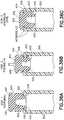
- the membrane 402is assembled with a corresponding connector 502 by initial positioning the opposing end 432 of the membrane 402 within a central opening 504 of the connector 502 as shown in Fig. 36A .
- the membrane 402is then pushed or forced into the opening 504 and past the annular protrusion 506 of the connector 502.
- the annular protrusion 506compresses and engages the membrane 402 as the membrane 402 is inserted into the connector 502.
- the membrane 402is pushed into the connector 502 until the annular groove 434 of the membrane 402 is aligned with and receives the annular protrusion 506 of the connector 502 thereby creating an interference fit between the connector 502 and the membrane 402.
- the intermediate portion of the membrane 402 between the first end 430 and the opposing end 432 of the membranehas an interference fit with the connector 502, which creates a positive internal pressure to promote self-sealing when pierced with a cannula or engaged with another connector.
- the first end 430 of the membraneextends beyond the connector 502 so that when the membrane 402 and connector 502 are mated with a corresponding membrane and connector, the first end 430 of the membrane is not restricted thereby improving the resealing performance of the membrane 402 when pierced by a cannula.
- an assembly tool 510is provided to assist in the second step of inserting the membrane 402 within the connector 502.
- the assembly tool 510includes a central opening 512 and a tapered surface 514, such as a frusto-conical shaped surface.
- the central opening 512 of the assembly tool 510is aligned with the opening 504 of the connector 502.
- the membraneis then pushed and inserted into the opening 512 of the assembly tool 510 with the membrane 402 engaging the tapered surface 514 of the tool 510 to compress the membrane and allow for easier insertion of the membrane 402 into the connector 502.
- the membrane 402is otherwise assembled with the connector 502 in the same manner as described above in connection with Figs. 36A-36C with the annular groove 434 of the membrane receiving the annular protrusion 506 of the connector 502.
Landscapes
- Health & Medical Sciences (AREA)
- Animal Behavior & Ethology (AREA)
- Veterinary Medicine (AREA)
- Public Health (AREA)
- General Health & Medical Sciences (AREA)
- Life Sciences & Earth Sciences (AREA)
- Heart & Thoracic Surgery (AREA)
- Pharmacology & Pharmacy (AREA)
- Physics & Mathematics (AREA)
- Fluid Mechanics (AREA)
- Hematology (AREA)
- Biomedical Technology (AREA)
- Anesthesiology (AREA)
- Engineering & Computer Science (AREA)
- Pulmonology (AREA)
- Infusion, Injection, And Reservoir Apparatuses (AREA)
- Medical Preparation Storing Or Oral Administration Devices (AREA)
- Separation Using Semi-Permeable Membranes (AREA)
- Electrotherapy Devices (AREA)
Description
- The present disclosure relates generally to a connection system. More particularly, the present disclosure relates to a connection system for a first medical device component and a second medical device component.
- Some medical components, such as intravenous line connectors, require connection to other components, such as to intravenous lines or to syringe adapter or injector assemblies. Typical connection systems for medical device components include a single path for connection and disconnection. Such connection systems involve reverse movements in the same path for connection and disconnection.
US 4 564 054 A discloses a connection device of the related art that comprises a bayonet coupling. There is a need for a connection system for medical device components that is intuitive to connect and disconnect while minimizing the risk of inadvertent disconnection. - The present disclosure provides a connection system for connecting a first medical device component to a second medical device component. The connection system of the present disclosure provides for quick and intuitive coupling and decoupling of two opposing medical device components through the use of a connection path and a disconnection path, the connection path being distinct from the disconnection path. Furthermore, the connection system of the present disclosure provides audible and tactile connection feedback through the use of elastically deformable connection elements.
- In accordance with an embodiment of the present invention, a system includes a first medical device component having a first end, a second end, and a sidewall extending therebetween, the sidewall having an exterior surface and an interior surface, the interior surface of the sidewall having a first projecting element; and a second medical device component having a first connection channel, a first disconnection channel, and a first securement element disposed between the first connection channel and the first disconnection channel, the first connection channel distinct from the first disconnection channel, wherein with the first projecting element of the first medical device component received within the first connection channel of the second medical device component, the first connection channel guides the first projecting element to the first securement element, wherein with the first projecting element engaged with the first securement element, the first medical device component is secured to the second medical device component, and wherein with the first projecting element of the first medical device component received within the first disconnection channel of the second medical device component, the first disconnection channel guides the first projecting element out from the first disconnection channel thereby disengaging the first medical device component from the second medical device component
- In one configuration, the first medical device component is an injector adapter and the second medical device component is a vial adapter. In another configuration, the first medical device component is an injector adapter and the second medical device component is an IV line adapter. In yet another configuration, the interior surface of the sidewall of the first medical device component includes a second projecting element spaced from the first projecting element. In one configuration, the second medical device component further includes a second connection channel, a second disconnection channel, and a second securement element disposed between the second connection channel and the second disconnection channel, the second connection channel distinct from the second disconnection channel. In another configuration, with the second projecting element of the first medical device component received within the second connection channel of the second medical device component, the second connection channel guides the second projecting element to the second securement element, wherein with the second projecting element engaged with the second securement element, the first medical device component is secured to the second medical device component, and wherein with the second projecting element of the first medical device component received within the second disconnection channel of the second medical device component, the second disconnection channel guides the second projecting element out from the second disconnection channel thereby disengaging the first medical device component from the second medical device component. In yet another configuration, the second medical device component further includes a first step member disposed between the first securement element and the first disconnection channel and a second step member disposed between the second securement element and the second disconnection channel. In one configuration, with the first projecting element engaged with the first securement element, rotation of the first medical device component in a counter-clockwise direction relative to the second medical device component disengages the first projection element from the first securement element and moves the first projection element over the first step member and into the first disconnection channel. In another configuration, with the second projecting element engaged with the second securement element, rotation of the first medical device component in a counter-clockwise direction relative to the second medical device component disengages the second projection element from the second securement element and moves the second projection element over the second step member and into the second disconnection channel. In yet another configuration, with the first projecting element engaged with the first securement element, rotation of the first medical device component in a clockwise direction relative to the second medical device component disengages the first projection element from the first securement element and moves the first projection element over the first step member and into the first disconnection channel. In another configuration, with the second projecting element engaged with the second securement element, rotation of the first medical device component in a clockwise direction relative to the second medical device component disengages the second projection element from the second securement element and moves the second projection element over the second step member and into the second disconnection channel. In yet another configuration, the first projecting element includes an elastically deformable tab. In one configuration, the first securement element includes a recess.
- The above-mentioned and other features and advantages of this disclosure, and the manner of attaining them, will become more apparent and the disclosure itself will be better understood by reference to the following descriptions of embodiments of the disclosure taken in conjunction with the accompanying drawings, wherein:
Fig. 1 is an exploded, perspective view of a first medical device component and a second medical device component including a connection system in accordance with an embodiment of the present invention.Fig. 2 is a detailed, fragmentary view of a portion of the first medical device component and a portion of the second medical device component ofFig. 1 including a connection system in accordance with an embodiment of the present invention.Fig. 3 is a perspective view of a portion of a connection system of the present disclosure illustrating a connection path that is distinct from a disconnection path in accordance with an embodiment of the present invention.Fig. 4 is a front elevation view of a first medical device component and a second medical device component including a connection system of the present disclosure illustrating an elastically deformable portion in accordance with an embodiment of the present invention.Fig. 5A is a perspective view of a first medical device component connected to a second medical device component by a connection system in accordance with an embodiment of the present invention.Fig. 5B is a cross-sectional view of the system ofFig. 5A taken alongline 5B-5B ofFig. 5A in accordance with an embodiment of the present invention.Fig. 5C is a cross-sectional view of the system ofFig. 5A taken alongline 5C-5C ofFig. 5A in accordance with an embodiment of the present invention.Fig. 6A is a perspective view of a first medical device component connected to a second medical device component by a connection system in accordance with an embodiment of the present invention.Fig. 6B is a cross-sectional view of the system ofFig. 6A taken alongline 6B-6B ofFig. 6A in accordance with an embodiment of the present invention.Fig. 6C is a cross-sectional view of the system ofFig. 6A taken alongline 6C-6C ofFig. 6A in accordance with an embodiment of the present invention.Fig. 7 is a perspective, cross-sectional view of a first medical device component connected to a second medical device component by a connection system in accordance with an embodiment of the present invention.Fig. 8A is a perspective view of a first medical device component connected to a second medical device component by a connection system in accordance with an embodiment of the present invention.Fig. 8B is a cross-sectional view of the system ofFig. 8A in accordance with an embodiment of the present invention.Fig. 8C is a cross-sectional view of the system ofFig. 8A taken alongline 8C-8C ofFig. 8A in accordance with an embodiment of the present invention.Fig. 9A is an exploded, perspective view of a first medical device component and a second medical device component in accordance with an embodiment of the present invention.Fig. 9B is a cross-sectional view of the system ofFig. 9A taken alongline 9B-9B ofFig. 9A in accordance with an embodiment of the present invention.Fig. 10 is a perspective view of a first medical device component connected to a second medical device component by a connection system in accordance with an embodiment of the present invention.Fig. 11A is a perspective view of a first medical device component connected to a second medical device component by a connection system in accordance with another embodiment of the present invention.Fig. 11B is a side elevation view of a first medical device component connected to a second medical device component by a connection system in accordance with an embodiment of the present invention.Fig. 11C is a cross-sectional view of the first medical device component connected to the second medical device component taken alongline 11C-11C ofFig. 11B in accordance with an embodiment of the present invention.Fig. 12A is a perspective view of an intravenous line adapter in accordance with an embodiment of the present invention.Fig. 12B is a top view of an intravenous line adapter in accordance with an embodiment of the present invention.Fig. 12C is a perspective view of a first side of an intravenous line adapter in accordance with an embodiment of the present invention.Fig. 12D is a perspective view of a second side of an intravenous line adapter in accordance with an embodiment of the present invention.Fig. 13A is a perspective view of an intravenous line adapter in accordance with an embodiment of the present invention.Fig. 13B is a cross-sectional view of the intravenous line adapter ofFig. 13A taken alongline 13B-13B ofFig. 13A in accordance with an embodiment of the present invention.Fig. 14A is a perspective view of an intravenous line adapter in accordance with an embodiment of the present invention.Fig. 14B is a cross-sectional view of the intravenous line adapter ofFig. 14A taken alongline 14B-14B ofFig. 14A in accordance with an embodiment of the present invention.Fig. 15 is an exploded, perspective view of an injector adapter in accordance with an embodiment of the present invention.Fig. 16 is an assembled, cross-sectional view of the injector adapter ofFig. 15 in accordance with an embodiment of the present invention.Fig. 17 is another exploded, perspective view of an injector adapter in accordance with an embodiment of the present invention.Fig. 18 is a perspective view of an injector adapter in accordance with an embodiment of the present invention.Fig. 19A is an exploded, perspective view of a vial adapter in accordance with an embodiment of the present invention.Fig. 19B is a side, perspective view of a vial adapter in accordance with an embodiment of the present invention.Fig. 19C is a perspective view of a vial adapter in accordance with an embodiment of the present invention.Fig. 19D is a plan view of a vial adapter in accordance with an embodiment of the present invention.Fig. 19E is a bottom view of a vial adapter in accordance with an embodiment of the present invention.Fig. 19F is a cross-sectional view of the vial adapter ofFig. 19B in accordance with an embodiment of the present invention.Fig. 19G is a perspective view of a vial access system in accordance with an embodiment of the present invention.Fig. 20A is a perspective view of a vial adapter connected to a vial in accordance with an embodiment of the present invention.Fig. 20B is a cross-sectional view of the vial adapter connected to the vial ofFig. 20A in accordance with an embodiment of the present invention.Fig. 21A is a perspective view of a vial adapter connected to a vial in accordance with an embodiment of the present invention.Fig. 21B is another perspective view of a vial adapter connected to a vial in accordance with an embodiment of the present invention.Fig. 21C is a cross-sectional view of a vial adapter connected to a vial taken alongline 21C-21C ofFig. 21B in accordance with an embodiment of the present invention.Fig. 22 is an assembled, perspective view of a system in accordance with an embodiment of the present invention.Fig. 23A is an assembled, perspective view of a system in accordance with an embodiment of the present invention.Fig. 23B is a cross-sectional view of the system taken alongline 23B-23B ofFig. 23A in accordance with an embodiment of the present invention.Fig. 23C is a detailed, fragmentary view ofFig. 23B in accordance with an embodiment of the present invention.Fig. 24 is a cross-sectional view of the system ofFig. 22 with the system inverted and a cannula seal in communication with a vial seal and a cannula in fluid communication with a substance contained within a vial chamber in accordance with an embodiment of the present invention.Fig. 25 is a cross-sectional view of the system ofFig. 22 with the system inverted and a cannula seal not in communication with a vial seal and a portion of a substance contained within a vial chamber transferred to a barrel chamber via a cannula in accordance with an embodiment of the present invention.Fig. 26 is a cross-sectional view of the system ofFig. 25 with a portion of a substance contained within a vial chamber transferred to a barrel chamber via a cannula and the injector adapter positioned adjacent an intravenous line adapter in accordance with an embodiment of the present invention.Fig. 27 is an exploded, perspective view of a first medical device component and a second medical device component including a connection system in accordance with another embodiment of the present invention.Fig. 28 is a perspective view of a connection system in accordance with another embodiment of the present invention.Fig. 29 is a cross-sectional view of the system ofFig. 28 in accordance with another embodiment of the present invention.Fig. 30 is a perspective view of a connector in accordance with another embodiment of the present invention.Fig. 31 is a side, perspective view of a connector in accordance with another embodiment of the present invention.Fig. 32 is a perspective view of a membrane in accordance with another embodiment of the present invention.Fig. 33 is a side elevation view of a membrane in accordance with another embodiment of the present invention.Fig. 34 is a perspective view of a first luer component in accordance with another embodiment of the present invention.Fig. 35 is a perspective view of a connection system and a first luer component connected to a second luer component and an IV line in accordance with another embodiment of the present invention.Fig. 36A is a cross-sectional view of a first step in assembling the membrane ofFig. 32 with a connector according to one embodiment of the present invention.Fig. 36B is a cross-sectional view of a second step in assembling the membrane ofFig. 32 with a connector according to one embodiment of the present invention.Fig. 36C is a cross-sectional view of a third step in assembling the membrane ofFig. 32 with a connector according to one embodiment of the present invention.Fig. 37 is a cross-sectional view of a second step in assembling the membrane ofFig. 32 with a connector according to a further embodiment of the present invention.- For purposes of the description hereinafter, the terms "upper", "lower", "right", "left", "vertical", "horizontal", "top", "bottom", "lateral", "longitudinal", and derivatives thereof shall relate to the invention as it is oriented in the drawing figures. However, it is to be understood that the invention may assume various alternative variations, except where expressly specified to the contrary. It is also to be understood that the specific devices illustrated in the attached drawings, and described in the following specification, are simply exemplary embodiments of the invention. Hence, specific dimensions and other physical characteristics related to the embodiments disclosed herein are not to be considered as limiting.
- The present disclosure provides a connection system for connecting a first medical device component to a second medical device component.
Fig. 1 illustrates the connection system of the present disclosure connecting the housing of an injector adapter to an intravenous line adapter according to an exemplary embodiment of the present disclosure.Fig. 11A illustrates the connection system of the present disclosure connecting the housing of an injector adapter to a vial adapter according to another exemplary embodiment of the present disclosure. Furthermore, the connection system of the present disclosure may be used to connect other medical device components. - Referring to
Figs. 15-18 ,injector adapter 12 generally includes acannula 20, acannula seal 22, aspring 24, aneedle hub 26, acannula stabilizing member 28, ahousing 29, agliding ring 31, a one-way valve 232, and afilter 234. Referring toFig. 15 ,cannula 20 includes adistal end 30, aproximal end 32, and alumen 34 extending therebetween.Distal end 30 is in fluid communication withproximal end 32 vialumen 34 ofcannula 20. As shown inFig. 24 ,distal end 30 ofcannula 20 is capable of piercingcannula seal 22 and avial seal membrane 344 to place avial chamber 96 in fluid communication with a barrel chamber 176 viacannula 20. In one embodiment,distal end 30 ofcannula 20 defines a sharp point. Injector adapter 12 is compatible with a system for the closed transfer of fluids that provides substantially leak-proof sealing and pressure balancing during engagement of a cannula with a vial, during transfer of a substance from a vial chamber to a barrel chamber via the cannula, and during disengagement of the cannula from the vial. Such a leak-proof sealing of the system substantially prevents leakage of both air and liquid during use of the system. The system is compatible with a needle and syringe assembly for accessing a medication contained within a vial for administering the medication to a patient. The system is also compatible to be used with a drug reconstitution system.- Referring to
Figs. 15-18 ,cannula seal 22 generally includes a self-sealing seal secured overcannula 20 so thatcannula seal 22 enclosescannula 20 in a sealed position (Fig. 25 ) to provide a substantially leak-proof seal preventing any liquid, air, or medication residue from being exposed to a health care provider transferring, reconstituting, transporting, or administering a drug usinginjector adapter 12. Referring toFig. 25 , withcannula seal 22 in the sealed position,cannula seal 22 enclosescannula 20 to also prevent accidental needle stick injuries to a user ofinjector adapter 12.Cannula seal 22 includes adistal end 40, aproximal end 42, annularribbed members 46 extending therebetween, and a shoulder portion 44 (Fig. 16 ) located on aninterior wall 48 neardistal end 40 ofcannula seal 22. In one embodiment,distal end 40 ofcannula seal 22 includes anannular cavity 41. Thedistal end 40 ofcannula seal 22 defines a convex surface and has a transverse cross-sectional shape that is generally circular, although it is contemplated that other shapes and sizes ofdistal end 40 may be used. For example,distal end 40 ofcannula seal 22 can have other multi-sided polygon cross-sectional shapes, such as square or oval cross-sectional shapes. Thecannula seal 22 may have a length that is about equal to a length of thecannula 20 and, upon assembly of theinjector adapter 12, thecannula seal 22 may extend about the entire length of thecannula 20. - In one embodiment,
cannula seal 22 comprises a resilient material. For example,cannula seal 22 is preferably a unitary device molded of any flexible, elastomeric material conventionally used for fabricating gas-proof closures.Cannula seal 22 may be formed of a natural rubber material, polyurethane elastomers, butyl rubbers, or similar materials. It is contemplated thatcannula seal 22 is formed of a material having a Shore A hardness of approximately 10 to 50. It is also envisioned thatcannula seal 22 can have other material hardness values that would provide an appropriate self-sealing material to provide a substantially leak-proof seal withcannula seal 22 in the sealed position, thereby preventing any liquid or medication residue from being exposed to a health care provider transferring, reconstituting, transporting, or administering a drug usinginjector adapter 12. In one embodiment,cannula seal 22 comprises a resilient sleeve. - Referring to
Fig. 15 ,spring 24 includes adistal end 60 and aproximal end 62.Spring 24 provides a biasing force that promotescannula seal 22 to enclosecannula 20 in the sealed position as will be described in more detail below. Referring toFig. 16 ,spring 24 is disposed overcannula 20 such thatspring 24 is radially positioned betweencannula 20 andcannula seal 22, i.e.,cannula seal 22 enclosesspring 24 andcannula 20. - Referring to
Fig. 16 ,spring 24 is disposed overcannula 20 and withincannula seal 22 such thatdistal end 60 ofspring 24 engagesshoulder portion 44 ofcannula seal 22. In this manner,spring 24 exerts the biasing force onshoulder portion 44 ofcannula seal 22.Shoulder portion 44 ofcannula seal 22 also ensures thatspring 24 is secured betweenshoulder portion 44 andneedle hub 26. - Referring to
Figs. 15-18 ,needle hub 26 generally includes adistal end 50 and aproximal end 52.Proximal end 52 ofneedle hub 26 includes abarrel connection portion 54. In one embodiment,barrel connection portion 54 is a female luer connector that is configured to mate with a male luer connector, although other suitable connectors may be utilized. Thebarrel connection portion 54 includes a projection that is configured to be received by a corresponding threaded portion of the male luer connector. Other arrangements for thebarrel connection portion 54 may be utilized that deter undesired disconnection from theneedle hub 26.Needle hub 26 supports and is secured to a portion ofcannula 20. In one embodiment, theneedle hub 26 is secured to thecannula 20 via an adhesive, such as an epoxy, although other suitable arrangements for securing thecannula 20 to theneedle hub 26 may be utilized.Distal end 50 ofneedle hub 26 also provides a connection withproximal end 62 ofspring 24 so thatdistal end 60 ofspring 24 may be compressed relative toproximal end 62 ofspring 24 whencannula 20 piercescannula seal 22 as will be described in more detail below. Withspring 24 compressed,spring 24 exerts a biasing force that promotescannula seal 22 to elastically enclosecannula 20. Referring toFig. 25 , in one embodiment, withcannula seal 22 in the sealed position,spring 24 is loaded betweenshoulder portion 44 ofcannula seal 22 andneedle hub 26 in a slightly compressed position so thatspring 24 exerts a biasing force that retainscannula seal 22 in the sealed position. - In one embodiment, referring to
Figs. 15-18 , annularribbed members 46 ofcannula seal 22 provide an additional biasing force that retainscannula seal 22 in the sealed position. Referring toFig. 23C , ascannula 20 is brought into contact withvial adapter 14, annularribbed members 46 ofcannula seal 22 andspring 24 are compressed ascannula 20 piercescannula seal 22 andvial adapter 14. With annular ribbedmembers 46 ofcannula seal 22 compressed, annularribbed members 46 exert an additional biasing force that promotescannula seal 22 to elastically enclosecannula 20. - Referring to
Figs. 15-18 ,housing 29 generally includes a distal orfirst end 110, a proximal orsecond end 112, and asidewall 114 extending therebetween.Sidewall 114 ofhousing 29 defines ahousing chamber 115.Housing chamber 115 is sized and shaped to contain and house the components ofinjector adapter 12. Thesidewall 114 ofhousing 29 includes anexterior wall surface 116 and aninterior wall surface 118. In one embodiment, theinterior wall surface 118 of thesidewall 114 includes aconnection element 120. Referring toFig. 16 ,connection element 120 extends inwardly frominterior wall surface 118 ofsidewall 114 intohousing chamber 115 adjacentdistal end 110. As discussed in detail below,connection element 120 is engageable with a connection element of a vial adapter or an IV line adapter to secureinjector adapter 12 to a vial adapter or an IV line adapter such that significant relative movement betweeninjector adapter 12 and the vial adapter or IV line adapter is prevented. In one embodiment,connection element 120 comprises a first projecting member 121. In one embodiment, first projecting member 121 includes an elastically deformable tab for engagement with a connection element of a vial adapter or an IV line adapter as described in more detail below. In one embodiment, referring toFig. 4 ,housing 29 also includes an elastically deformable portion for engagement with a connection element of a vial adapter or an IV line adapter as described in more detail below. - In one embodiment, the
interior wall surface 118 of thesidewall 114 includes asecond connection element 122. Referring toFig. 17 ,second connection element 122 extends inwardly frominterior wall surface 118 ofsidewall 114 intohousing chamber 115 adjacentdistal end 110.Second connection element 122 is spaced a distance fromfirst connection element 120. In one embodiment,second connection element 122 is spaced approximately 180 degrees (180°) fromfirst connection element 120.Second connection element 122 is engageable with a connection element of a vial adapter or an IV line adapter to secureinjector adapter 12 to a vial adapter or an IV line adapter. In one embodiment,second connection element 122 comprises a second projecting member 123. In one embodiment, second projecting member 123 includes an elastically deformable tab for engagement with a connection element of a vial adapter or an IV line adapter as described in more detail below. - The first and
second connection elements injector adapter 12 form a first portion of a connection system of the present disclosure which is compatible with connection elements of a vial adapter or an IV line adapter which form a second portion of a connection system of the present disclosure as discussed in more detail below. - In one embodiment, a material that is capable of elastic flexing without cracking is used to form first and
second connection elements injector adapter 12. It is contemplated that flexible polymers may be used to form first andsecond connection elements injector adapter 12. For example, flexible polymers such as polyolefines may be used, e.g., polypropylene, polyethylene, and their co-polymers. Housing 29 provides a protective housing which seals the components ofinjector adapter 12 withinhousing 29, i.e.,housing 29 provides a leak prevention and protection enclosure, protects the components ofinjector adapter 12 contained withinhousing 29, and/or maintains a sealed, sterilized environment withinhousing 29.Housing 29 also providesconnection elements injector adapter 12 to a vial adapter or an IV line adapter. In one embodiment, referring toFig. 4 ,housing 29 also includes an elastically deformable portion for engagement with a connection element of a vial adapter or an IV line adapter as described in more detail below.- Referring to
Figs. 15-18 , in one embodiment,injector adapter 12 includescannula stabilizing member 28.Cannula stabilizing member 28 includes adistal end 70, aproximal end 72, and anannular ring 74 therebetween. Referring toFig. 16 ,cannula stabilizing member 28 is disposed withincannula seal 22 such thatannular ring 74 ofcannula stabilizing member 28 engagesshoulder portion 44 ofcannula seal 22. In this position,cannula stabilizing member 28 supports a portion ofcannula 20 and provides stability tocannula 20 during engagement ofcannula 20 with a vial or other device. Withcannula stabilizing member 28 positioned withincannula seal 22,spring 24 is disposed overcannula 20 and withincannula seal 22 such thatdistal end 60 ofspring 24 engagesannular ring 74 ofcannula stabilizing member 28. In this manner,spring 24 exerts the biasing force onannular ring 74 ofcannula stabilizing member 28 which exerts the biasing force onshoulder portion 44 ofcannula seal 22. - Referring to
Figs. 16 and17 , in one embodiment,injector adapter 12 includes glidingring 31.Gliding ring 31 includes an exterior wall surface, i.e., agliding surface 252 and aninterior surface 254. In one embodiment, theinterior surface 254 of glidingring 31 includes anannular protrusion 256. Theannular protrusion 256 extends radially inwards frominterior surface 254. Referring toFig. 16 , glidingring 31 is disposed withinhousing 29 such thatannular protrusion 256 is received withinannular cavity 41 ofcannula seal 22 to secure thegliding ring 31 to thecannula seal 22 such that thegliding ring 31 is positioned betweencannula seal 22 andinterior wall surface 118 ofhousing 29. In this position, glidingring 31 supports a portion ofcannula seal 22 and provides stability tocannula seal 22 withinhousing 29 during engagement ofcannula 20 with a vial or other device.Gliding ring 31 also provides stability tocannula seal 22 withcannula seal 22 moving withinhousing 29. - Referring to
Figs. 15-18 , in one embodiment,injector adapter 12 is configured to provide anaspiration arrangement 230 to allow air to enter theinjector adapter 12 for aspirating air into a syringe barrel while using seal and pressure equalization system 10. In particular, theaspiration arrangement 230 allows a user to aspirate air into the barrel chamber 176 afterinjector adapter 12 is secured to thebarrel assembly 16. In one embodiment, theaspiration arrangement 230 includes a one-way valve 232 andfilter 234. As shown inFig. 16 , theneedle hub 26 includes aninner wall 236 and anouter wall 238 that defines anannular recess 240. Theneedle hub 26 further defines at least onepassageway 242 that extends perpendicularly to a longitudinal axis of thehub 26. Thepassageway 242 extends through theinner wall 236. Theouter wall 238 defines acutout 243 that is configured to receive thefilter 234. Thecutout 243 is in fluid communication with thepassageway 242 and theannular recess 240. In one embodiment, as shown inFigs. 15-17 , thefilter 234 is a flat filter sheet positioned within thecutout 243, although other suitable arrangements may be utilized. For example, thefilter 234 may be ring-shaped and fitted within theannular recess 240 rather than being positioned within thecutout 243. Thefilter 234 may be any suitable commercially available filter, such as a particulate air filter having a pore size of 0.2 µm or larger. Thefilter 234 may be configured remove viable micro-organisms. - Referring again to
Fig. 16 , in one embodiment, the one-way valve 232 is embodied as anextension 244 of thecannula seal 22 that extends into theneedle hub 26. Theextension 244 is formed integrally with thecannula seal 22, although theextension 244 may be formed separately. Theextension 244 of thecannula seal 22 abuts and extends along at least a portion of aninner surface 246 of theinner wall 236. Theextension 244 is configured to selectively allow the flow of outside air through thepassageway 242 and thefilter 234 and into thecannula seal 22. In particular, in response to a pressure drop within thecannula seal 22 caused by aspiration, theextension 244 will deflect inwardly to open thepassageway 242 and allow outside air to be drawn into the barrel chamber 176 ofbarrel assembly 16. After aspiration, theextension 244 will return to its original position to block or close thepassageways 242. When thecannula seal 22 is under a positive pressure, theextension 244 is forced radially outward and continues to block and seal thepassageway 242. Air may first be injected into thevial chamber 96 ofvial 90 prior to withdrawing fluid, such assubstance 98, from thevial chamber 96. Accordingly, the one-way valve 232 andfilter 234 allows a user to aspirate air into the barrel chamber 176 after theinjector adapter 12 is secured to thebarrel assembly 16. Furthermore, thefilter 234 is configured to filter the outside air that is aspirated into thebarrel assembly 16, which advantageously allows clean filter air to be injected into thevial chamber 96. - Referring to
Figs. 22-26 ,proximal end 52 ofneedle hub 26 is attached to abarrel 160 ofbarrel assembly 16. Withneedle hub 26 supporting a portion ofcannula 20 and withproximal end 52 ofneedle hub 26 attached tobarrel 160 ofbarrel assembly 16,needle hub 26 attachescannula 20 tobarrel assembly 16 such thatcannula 20 is in fluid communication with barrel chamber 176 ofbarrel 160. - Referring to
Fig. 23B ,barrel assembly 16 includesbarrel 160, aplunger rod 162, and astopper 164.Barrel assembly 16 may be adapted for the dispensing and delivery of a fluid and/or collection of a fluid. For example,barrel assembly 16 may be used for injection or infusion of fluid such as a medication into a patient.Barrel assembly 16 is contemplated for use in connection with a needle, such as by connectingbarrel assembly 16 to cannula 20 as described, connectingbarrel assembly 16 to a separate needle assembly (not shown), or alternatively, for connection with an intravenous (IV) connection assembly such asIV line adapter 18. It can be appreciated that the present disclosure can be used with any type of syringe assembly, including, but not limited to, metered dose syringes, aspiration syringes for withdrawing fluid from a patient or medication from a container or vial, and the like. - Referring to
Figs. 12A-14B ,IV line adapter 18 includesfirst end 130 and opposingsecond end 131.IV line adapter 18 provides a compact and accessible connector for connecting a cartridge or barrel containing a reconstituted drug to an intravenous line or an injection apparatus for administering the drug to a patient. First end 130 ofIV line adapter 18 includes aconnection system 132.Connection system 132 ofIV line adapter 18 forms a portion of a connection system of the present disclosure which is compatible with aconnection system injector adapter 12 which form another portion of a connection system of the present disclosure as discussed in more detail below.- Referring to
Figs. 12A-12C , in one embodiment,connection system 132 includes afirst connection element 133 disposed atfirst end 130 ofIV line adapter 18 which is engageable with aconnection element injector adapter 12 to secure theinjector adapter 12 toIV line adapter 18. In one embodiment,first end 130 ofIV line adapter 18 includes asecond connection element 134.Second connection element 134 is spaced a distance fromfirst connection element 133. In one embodiment,second connection element 134 is spaced approximately 180 degrees (180°) fromfirst connection element 133.Second connection element 134 is engageable with aconnection element injector adapter 12 to secure theinjector adapter 12 toIV line adapter 18 such that significant relative movement betweeninjector adapter 12 andIV line adapter 18 is prevented. - Referring to
Figs. 12A-12C ,first connection element 133 ofconnection system 132 includes afirst connection path 136, afirst disconnection path 138, and afirst securement element 140 disposed between thefirst connection path 136 andfirst disconnection path 138. In one embodiment,first connection path 136,first disconnection path 138, andfirst securement element 140 together generally define a U-shaped path.First connection path 136 is distinct fromfirst disconnection path 138. In this manner, the distinct connection and disconnection paths allow for the fine tuning of tactile and audible responses separately for connection and disconnection movements. In one embodiment,divider wall 139 is disposed betweenfirst connection path 136 andfirst disconnection path 138. - It is contemplated that most polymers may be used for
first connection element 133 ofIV line adapter 18. In one embodiment, a wide variety of thermoplastic and thermosetting polymers and similar materials may be used to formfirst connection element 133 ofIV line adapter 18. In one embodiment,first connection element 133 ofIV line adapter 18 is made from a rigid material such as a hard plastic, metal, or ceramic material. The important characteristics of the materials used to makefirst connection element 133 ofIV line adapter 18 is that they are a more rigid material than the materials used to formconnection element 120 ofinjector adapter 12. - In one embodiment,
first connection path 136 comprises a first connection channel. In one embodiment,first disconnection path 138 comprises a first disconnection channel. In one embodiment,first securement element 140 comprises a locking recess. First connection path 136 includes aconnection guide surface 141, a firstconnection guide wall 142, and a secondconnection guide wall 143 which together form a channel that guidesconnection element 120 ofinjector adapter 12 to enter engagement withIV line adapter 18 as described in more detail below.Connection guide surface 141 includes anentry portion 144 and anexit portion 145adjacent securement element 140. In one embodiment,guide surface 141 tapers upwards fromentry portion 144 to exitportion 145. In this manner, guidesurface 141 receives, guides, and deformsconnection element 120 ofinjector adapter 12 as described in more detail below.First connection path 136 includes astep member 135 disposed betweenfirst securement element 140 andfirst disconnection path 138.Step member 135 includes anexit recess step 147, an enterdisconnection path step 148, and atop step surface 149 disposed therebetween.Step member 135 provides a component that allowsconnection element 120 of injector adapter to be rotated out from engagement withsecurement element 140. Also,step member 135 can be used to tune resistance and provide tactile feel during a disconnection movement as described in more detail below.First disconnection path 138 includes adisconnection guide surface 150, a firstdisconnection guide wall 151, and a seconddisconnection guide wall 152 which together form a channel that guidesconnection element 120 ofinjector adapter 12 to exitIV line adapter 18 as described in more detail below.Disconnection guide surface 150 includes anentry portion 153adjacent step member 135 and anexit portion 154 that includes abarrier exit wall 155. In one embodiment,guide surface 150 tapers upwards fromentry portion 153 to exitportion 154. In this manner, guidesurface 150 receives, guides, and deformsconnection element 120 ofinjector adapter 12 as described in more detail below.- Referring to
Figs. 12B and12D ,second connection element 134 ofconnection system 132 includes asecond connection path 170, asecond disconnection path 171, and asecond securement element 172 disposed between thesecond connection path 170 andsecond disconnection path 171. In one embodiment,second connection path 170,second disconnection path 171, andsecond securement element 172 together generally define a U-shaped path.Second connection path 170 is distinct fromsecond disconnection path 171. In this manner, the distinct connection and disconnection paths allow for the fine tuning of tactile and audible responses separately for connection and disconnection movements. In one embodiment,divider wall 174 is disposed betweensecond connection path 170 andsecond disconnection path 171. - It is contemplated that most polymers may be used for
second connection element 134 ofIV line adapter 18. In one embodiment, a wide variety of thermoplastic and thermosetting polymers and similar materials may be used to formsecond connection element 134 ofIV line adapter 18. In one embodiment,second connection element 134 ofIV line adapter 18 is made from a rigid material such as a hard plastic, metal, or ceramic material. The important characteristics of the materials used to makesecond connection element 134 ofIV line adapter 18 is that they are a more rigid material than the materials used to formsecond connection element 122 ofinjector adapter 12. - In one embodiment,
second connection path 170 comprises a second connection channel. In one embodiment,second disconnection path 171 comprises a second disconnection channel. In one embodiment,second securement element 172 comprises a locking recess. Second connection path 170 includes aconnection guide surface 180, a firstconnection guide wall 181, and a secondconnection guide wall 182 which together form a channel that guidessecond connection element 122 ofinjector adapter 12 to enter engagement withIV line adapter 18 as described in more detail below.Connection guide surface 180 includes anentry portion 183 and anexit portion 184adjacent securement element 172. In one embodiment,guide surface 180 tapers upwards fromentry portion 183 to exitportion 184. In this manner, guidesurface 180 receives, guides, and deformssecond connection element 122 ofinjector adapter 12 as described in more detail below.Second connection path 170 includes astep member 173 disposed betweensecond securement element 172 andsecond disconnection path 171.Step member 173 includes anexit recess step 191, an enterdisconnection path step 192, and atop step surface 193 disposed therebetween.Step member 173 provides a component that allowssecond connection element 122 ofinjector adapter 12 to be rotated out from engagement withsecurement element 172. Also,step member 173 can be used to tune resistance and provide tactile feel during a disconnection movement as described in more detail below.Second disconnection path 171 includes adisconnection guide surface 185, a firstdisconnection guide wall 186, and a seconddisconnection guide wall 187 which together form a channel that guidessecond connection element 122 ofinjector adapter 12 to exitIV line adapter 18 as described in more detail below.Disconnection guide surface 185 includes anentry portion 188adjacent step member 173 and anexit portion 189 that includes abarrier exit wall 190. In one embodiment,guide surface 185 tapers upwards fromentry portion 188 to exitportion 189. In this manner, guidesurface 185 receives, guides, and deformssecond connection element 122 ofinjector adapter 12 as described in more detail below.First end 130 ofIV line adapter 18 includes apierceable barrier membrane 158. Thepierceable barrier membrane 158 provides for a liquid and gas tight seal between a piercing member of a barrel assembly and thepierceable barrier membrane 158 during fluid transfer of a medication to a patient so to minimize leakage and thereby prevent exposure of hazardous medicaments to a user.Barrier membrane 158 provides a self-sealing seal that, with a barrel assembly attached toIV line adapter 18, provides a leak-proof seal preventing any substance being administered to a patient from being exposed to a health care provider administering the medication. In one embodiment,barrier membrane 158 comprises a resilient material. For example,barrier membrane 158 is preferably a unitary device molded of any flexible, elastomeric material conventionally used for fabricating gas-proof closures.Barrier membrane 158 may be formed of a natural rubber material, polyurethane elastomers, butyl rubbers, or similar materials.- Referring to
Figs. 19A-19G ,vial adapter 14 includes avial access system 312 and apressure equalization system 314.Vial adapter 14 is configured to establish fluid communication between a first container and a second container. For example,vial adapter 14 is attachable to avial 90. Referring toFigs. 20A and20B ,vial 90 may be a standard drug vial of any type having an open head portion 93 covered by apierceable septum 94 of an elastomeric material.Walls 95 ofvial 90 definevial chamber 96 for containing asubstance 98.Vial septum 94 is engaged with head portion 93 ofvial 90 to seal thesubstance 98 withinvial chamber 96. Vial adapter 14 is compatible with a system for the closed transfer of fluids that provides substantially leak-proof sealing and pressure balancing during engagement of a cannula with a vial, during transfer of a substance from a vial chamber to a barrel chamber via the cannula, and during disengagement of the cannula from the vial.- As shown in
Figs. 19A-19F , withpressure equalization system 314 secured tovial access system 312,vial adapter 14 includes first end 302, opposing second end 303, and wall 304 extending between first end 302 and second end 303. Wall 304 defines an exterior profile 306 as will be described in more detail below. Withvial adapter 14 attached to avial 90, thevial adapter 14 provides a leak-proof seal and pressure equalization system that prevents any substance contained within a chamber of the vial from being exposed to a health care provider reconstituting, transporting, or administering a drug. - The fit between
vial adapter 14 and the packaging member provides a secure fit therebetween, such that, withvial adapter 14 received within the packaging member, the packaging member can be used as an interface between the hand of a user andvial adapter 14 so thatvial adapter 14 can be placed onto a vial without takingvial adapter 14 out of the packaging member. - Referring to
Fig. 19G ,vial access system 312 ofvial adapter 14 includesvial access housing 330 havingfirst end 332 and opposingsecond end 334.First end 332 ofvial access housing 330 includes a connection element orconnection system 336.First connection element 336 is engageable with aconnection element injector adapter 12 to secure theinjector adapter 12 tovial adapter 14. In one embodiment,first end 332 ofvial access housing 330 includes a second connection element or second connection system 339. Second connection element 339 is spaced a distance fromfirst connection element 336. In one embodiment, second connection element 339 is spaced approximately 180 degrees (180°) fromfirst connection element 336. Second connection element 339 is engageable with aconnection element injector adapter 12 to secure theinjector adapter 12 tovial adapter 14 such that significant relative movement betweeninjector adapter 12 andvial adapter 14 is prevented. - In one embodiment, the first and
second connection elements 336, 339 ofvial adapter 14 form a second portion of a connection system of the present disclosure which is compatible with connection elements of an injector adapter which form a first portion of a connection system of the present disclosure as discussed in more detail below. Figs. 19A-19G illustrate another exemplary embodiment of the present disclosure. The connection system of first andsecond connection elements 336, 339 ofvial adapter 14 illustrated inFigs. 19A-19G include similar components to the connection system offirst connection element 133 andsecond connection element 134 ofIV line adapter 18 illustrated inFigs. 12-14B , and the similar components are denoted by a reference number followed by the letter A. For the sake of brevity, these similar components and the similar steps of using the connection system of first andsecond connection elements 336, 339 ofvial adapter 14 will not all be discussed in conjunction with the embodiment illustrated inFigs. 19A-19G .First end 332 ofvial access housing 330 is substantially formed by aneck portion 333. In one embodiment,neck portion 333 may include a guiding groove arranged therein to guide corresponding guiding protrusions on a cannula adapter or syringe assembly, for example, to establish a secure attachment between the cannula adapter or syringe assembly andvial adapter 14 after which fluid communication can be established.- Referring to
Figs. 19A-19G , a vial connection member orvial engagement member 337 is disposed atsecond end 334 ofvial access housing 330. In one embodiment,vial connection member 337 includes a plurality of vial grip members 338 that are disposed atsecond end 334 ofvial access housing 330. Vial grip members 338 are attachable to avial 90 to securevial adapter 14 to thevial 90. Each vial grip member 338 includes ahook protrusion 340 arranged to engage a corresponding flange on a container such as avial 90 as shown inFigs. 20A and20B .Vial connection member 337 ofvial access housing 330 may be dimensioned to be attached to containers of any size and volume. In other embodiments,vial connection member 337 ofvial access housing 330 may include other connection mechanisms for securingvial adapter 14 tovial 90 such as a threaded portion, a snap fit mechanism, locking tabs, or other similar mechanism. - A
fluid transfer channel 342 extends substantially betweenfirst end 332 andsecond end 334 ofvial access housing 330. The purpose offluid transfer channel 342 is to permit a needle cannula to extend throughvial access housing 330 ofvial adapter 14 and to thereby permit fluid to be transferred throughvial adapter 14. - Referring to
Fig. 20B , a pierceable barrier member orvial seal membrane 344 is arranged in thefluid transfer channel 342 atfirst end 332 ofvial access housing 330. Thepierceable barrier member 344 provides for a liquid and gas tight seal between a piercing member and thepierceable barrier member 344 during fluid transfer so to minimize leakage and thereby prevent exposure of hazardous medicaments to a user.Vial seal membrane 344 provides a self-sealing seal that, withvial adapter 14 attached tovial 90 such thatvial seal membrane 344 is aligned withvial septum 94, provides a leak-proof seal preventing any substance contained withinvial chamber 96 from being exposed to a health care provider reconstituting, transporting, or administering a drug using system 10. Referring toFigs. 23C-25 ,vial seal membrane 344,vial sleeve seal 350, andcannula seal 22 provide a leak-proof seal that is liquid tight and airtight preventing any substance residue from being exposed to a health care provider while reconstituting or withdrawingsubstance 98 fromvial 90 tobarrel 160 viacannula 20. - In one embodiment,
vial seal membrane 344 comprises a resilient material. For example,vial seal membrane 344 is preferably a unitary device molded of any flexible, elastomeric material conventionally used for fabricating gas-proof closures.Vial seal membrane 344 may be formed of a natural rubber material, polyurethane elastomers, butyl rubbers, or similar materials. It is contemplated thatvial seal membrane 344 is formed of a material having a Shore A hardness of approximately 10 to 50. It is also envisioned thatvial seal membrane 344 can have other material hardness values that would provide an appropriate self-sealing material to provide a leak-proof seal withvial septum 94 ofvial 90 andcannula seal 22, thereby preventing any liquid or medication residue from being exposed to a health care provider reconstituting, transporting, or administering a drug using system 10. - Protruding out from
vial access housing 330 atsecond end 334 is a piercing member orspike member 346 which includes piercingtip 348. In one embodiment,fluid transfer channel 342 extends inside ofspike member 346. Thespike member 346 extends in a direction substantially parallel with the plurality of vial grip members 338 and serves the purpose of piercing a fluid container such as avial 90 during assembly ofvial adapter 14 to avial 90 as is shown in greater detail inFig. 20B . - In one embodiment, a
vial sleeve seal 350 is disposed over thespike member 346. Thevial sleeve seal 350 provides a seal betweenvial adapter 14 and avial 90 with the piercingtip 348 ofspike member 346 engaged with thevial 90. In one embodiment,vial sleeve seal 350 comprises a rubber spike sleeve. - Referring to
Figs. 19A-19F ,pressure equalization system 314 includespressure equalization housing 360 and toroidalexpandable balloon 362 which includes anexpansion chamber 366.Pressure equalization housing 360 defines a taperedexterior wall portion 361 and an interior annularring cavity portion 363. In one embodiment, taperedexterior wall portion 361 includes a plurality of stabilizingribs 365. In one embodiment, stabilizingribs 365 may extend in an axial direction along taperedexterior wall portion 361 ofpressure equalization housing 360 and theribs 365 may be spaced around a periphery ofpressure equalization housing 360.Expandable balloon 362 includes a variable volume.Pressure equalization housing 360 comprises a relatively rigid material andexpandable balloon 362 comprises a relatively flexible material. In one embodiment,expandable balloon 362 comprises a thin, transparent plastic film that is attached to pressureequalization housing 360 in a gastight manner. In one embodiment,expandable balloon 362 is designed as a bellow which is compressible and extendable and thus the volume of theexpansion chamber 366 ofexpandable balloon 362 can thereby be increased and decreased. In one embodiment, interior annularring cavity portion 363 ofpressure equalization housing 360 extends radially aroundvial access housing 330 andexpandable balloon 362 extends radially aroundvial access housing 330. Pressure equalization housing 360 provides a barrier wall member that protectsexpandable balloon 362 from being torn during engagement of a cannula with a vial, during transfer of a substance from a vial chamber to a barrel chamber via the cannula, and during disengagement of the cannula from the vial. In one embodiment, by havingexpandable balloon 362 extending radially around the entirety ofvial access housing 330, thevial adapter 14 is balanced such that a center of mass is positioned at about a longitudinal axis ofvial adapter 14. In one embodiment,expandable balloon 362 extends 360 degrees (360°) radially aroundvial access housing 330. In one embodiment, a portion of toroidalexpandable balloon 362 is not covered bypressure equalization housing 60. In this manner,expandable balloon 362 is capable of expanding in an axial direction.- In one embodiment,
pressure equalization housing 360 andvial access housing 330 are a single integral component. In another embodiment,pressure equalization housing 360 andvial access housing 330 are separate components andpressure equalization housing 360 is attachable tovial access housing 330 such that significant relative movement betweenpressure equalization housing 360 andvial access housing 330 is prevented. - Referring to
Fig. 19F , a pressure normalization channel 370 extends fromsecond end 334 ofvial access housing 330 to exit aperture 364 ofpressure equalization housing 360. Pressure normalization channel 370 is arranged to provide gas communication between theexpandable balloon 362 and the interior of avial 90 when thevial adapter 14 is connected to avial 90. Withvial adapter 14 connected to avial 90, a syringe or cannula assembly may be used to inject fluid into thevial 90 or to withdraw fluid therefrom as described in more detail below. In one embodiment, pressure normalization channel 370 extends from a portion of piercingtip 348 ofspike member 346 and substantially parallel withfluid transfer channel 342 insidespike member 346. The pressure normalization channel 370 diverts in a direction perpendicular tofluid transfer channel 342 substantially at shoulder portion 372 of pressure normalization channel 370. The pressure normalization channel 370 includes an inlet opening 374 arranged substantially at a portion of piercingtip 348 ofspike member 346 and an outlet opening 376 positioned substantially at exit aperture 364 ofpressure equalization housing 360. - Referring to
Figs. 19A and19F , in one embodiment, the pressure normalization channel 370 comprises a filter 380 arranged to cover a region of the pressure normalization channel 370. The filter 380 serves the purpose of preventing any fluid from a container, such as a vial, from reachingexpansion chamber 366 ofexpandable balloon 362. In one embodiment, the filter 380 is preferably a hydrophobic filter which permits gas to pass, but prevents liquid to pass. The filter 380 may be secured withinpressure equalization housing 360 via filter holder 382. - In one embodiment,
vial adapter 14 may also include a valve arrangement positioned in the proximity of outlet opening 376 of the pressure normalization channel 370. Such a valve arrangement prevents clogging of the filter 380 by providing a cracking pressure to the valve arrangement for the fluid which flows in a direction from the inlet opening 374 to the outlet opening 376 of the pressure normalization channel 370 while permitting preferably a minimal cracking pressure in the opposite direction. - The function and advantages of
vial adapter 14, according to the present disclosure, will be described in greater detail. When preparing and administering drugs, care has be taken to minimize, or preferably eliminate, the risk of exposing people, such as medical and pharmacological personnel, to toxic substances. Some drugs must be dissolved or diluted before they are administered, which involves transferring a solvent from one container to a sealed vial containing the drug in powder or liquid form, by means of a needle, for example. Drugs may be inadvertently released into the atmosphere in gas form or by way of aerosolization, during the withdrawal of the needle from the vial, and while the needle is inside the vial, if any pressure differential between the interior of the vial and surrounding atmosphere exists.Vial adapter 14 of the present disclosure eliminates this problem by usingpressure equalization system 314 ofvial adapter 14 that may be attached to a vial during the preparation of drugs. Thepressure equalization system 314 includes anexpandable balloon 362 which in communication with the interior of thevial 90 ensures that neither an increased pressure nor a vacuum can occur inside thevial 90 when gas or liquid is injected into or withdrawn from thevial 90. In one embodiment, theexpandable balloon 362 may be filled with cleaned or sterilized air prior to its use to ensure that the contents of thevial 90 do not become contaminated with air-borne particles such as dust, pollen, mold or bacteria, or other undesirable substances. - Referring to
Figs. 22-25 , thevial adapter 14 is assembled via itsconnection element 336 ofvial access housing 330 to acannula 20 ofinjector adapter 12 which in turn can be connected to a fluid container, such asbarrel assembly 16, and thevial adapter 14 is also assembled via itsvial connection members 337 with a second fluid container, such as avial 90. Asvial adapter 14 is assembled with thevial 90, the piercingtip 348 of thespike member 346 is pierced through aseptum 94 of thevial 90.Vial 90 may be a standard drug vial of any type having an open head portion covered by a pierceable septum of an elastomeric material. Thewalls 95 ofvial 90 define avial chamber 96 for containing asubstance 98. Thevial septum 94 is engaged with the head portion 93 ofvial 90 to seal a substance withinvial chamber 96. The plurality of vial grip members 338 fixedly connectvial adapter 14 to thevial 90 as thehook protrusions 340 of vial grip members 338 engage the correspondingflange 97 onvial 90 as shown inFig. 20B . After assembly, a user is able to insert fluid into thevial 90, or optionally to retract fluid from thevial 90. - As a fluid is inserted into the
vial 90, using thecannula 20 andbarrel assembly 16, an overpressure is created inside thevial 90.Pressure equalization system 314 ofvial adapter 14 permits pressure equalization between thevial 90 and theexpandable balloon 362. The pressure normalization channel 370 normalizes the pressure inside thevial 90 by relieving the pressure inside thevial 90 to theexpansion chamber 366 of theexpandable balloon 362 as shown inFigs. 21A-21C . - In other words,
Figs. 22-25 and21A-21C show thevial adapter 14 attached to thevial 90 and withcannula 20 inserted through thevial adapter 14 and into the interior of thevial 90. As a fluid is injected into thevial 90, or withdrawn from thevial 90, the pressure normalization channel 370 of thepressure equalization system 314 ofvial adapter 14 permits gas to flow from the interior of thevial 90 into theexpandable balloon 362 or from theexpansion chamber 366 of theexpandable balloon 362 to thevial 90, and thereby equalizes the pressure in the interior of thevial 90. Gas may enter theexpandable balloon 362 via outlet opening 376, however gas cannot exit from theexpandable balloon 362. This eliminates, or at least reduces the risk of any substance inside thevial 90 from being released into the atmosphere in gas form or by way of aerosolization during the insertion or withdrawal of a needle from thevial 90 or while a needle is inserted in thevial 90. It also eliminates, or reduces the risk of thevial 90 deforming due to the increased pressure inside thevial 90, whereby such deformation may cause leakage of the vial's 90 contents due to separation of theseptum 94 of thevial 90 from thewalls 95 of thevial 90, for example. - Referring to
Figs. 1-11C , the use of a connection system of the present disclosure to connect a first medical device component, e.g.,injector adapter 12, to a second medical device component, e.g.,IV line adapter 18, will now be described. - Initially, the
first connection element 120 ofinjector adapter 12 is aligned with thefirst connection path 136 ofIV line adapter 18 and thesecond connection element 122 ofinjector adapter 12 is aligned with thesecond connection path 170 ofIV line adapter 18 as shown inFigs. 1 ,2 , and9A . Next, a user can pushinjector adapter 12 andIV line adapter 18 together so thatfirst connection element 120 ofinjector adapter 12 entersfirst connection path 136 ofIV line adapter 18 andsecond connection element 122 ofinjector adapter 12 enterssecond connection path 170 ofIV line adapter 18. The path thatconnection elements injector adapter 12 follow, throughrespective connection paths IV line adapter 18, is shown in the connection illustration ofFig. 3 . Asconnection elements injector adapter 12 are guided throughrespective connection paths IV line adapter 18 fromrespective entry portions respective exit portions Fig. 3 ),connection elements guide surface connection elements respective exit portions connection elements connection elements securement elements Figs. 5A-5C . In this manner, asconnection elements connection elements securement elements connection elements connection elements respective exit portions elastic connection elements respective securement elements connection elements respective securement elements injector adapter 12 is connected toIV line adapter 18, such that, significant relative movement betweeninjector adapter 12 andIV line adapter 18 is prevented. - The locked position of
Fig. 4 illustrates the elasticallydeformable connection elements injector adapter 12 in a locked position in whichconnection elements respective securement elements Fig. 4 illustrates the elasticallydeformable connection elements injector adapter 12 in a deformed position in whichconnection elements IV line adapter 18. - Referring to
Fig. 3 , once it is desired to disconnectinjector adapter 12 fromIV line adapter 18,connection elements injector adapter 12 can be rotated in a counter-clockwise direction generally along arrow B to rotateconnection elements respective securement elements Step members connection elements injector adapter 12 to be rotated out from engagement withrespective securement elements connection elements connection elements connection elements securement elements connection elements exit recess step IV line adapter 18. The respective tapered exit recess steps 147, 191 ofIV line adapter 18 provide a ramp surface to deformrespective connection elements connection elements step members Figs. 6A-6C . Onceconnection elements step members connection elements respective entry portions disconnection paths connection elements connection elements respective entry portions disconnection paths connection elements connection elements respective entry portions disconnection paths connection elements respective entry portions disconnection paths step members - With
connection elements respective disconnection paths IV line adapter 18, a pulling force may be exerted in a direction generally along arrow C (Fig. 3 ) to pullinjector adapter 12 out fromIV line adapter 18. Asconnection elements injector adapter 12 are guided throughrespective disconnection paths IV line adapter 18 fromrespective entry portions respective exit portions Fig. 3 ),connection elements injector adapter 12 from being easily removed fromIV line adapter 18,barrier exit walls respective connection elements disconnection paths connection elements barrier exit walls connection elements barrier exit walls injector adapter 12 is removed fromIV line adapter 18 as shown inFig. 1 . - The connection system of the present disclosure provides for quick and intuitive coupling and decoupling of two opposing medical device components through the use of a connection path and a disconnection path, the connection path being distinct from the disconnection path. Furthermore, the connection system of the present disclosure provides audible and tactile connection feedback through the use of elastically deformable connection elements.
Figs. 11A-11C illustrate the use of a connection system of the present disclosure to connectinjector adapter 12 tovial adapter 14. As previously discussed, the connection system of first andsecond connection elements 336, 339 ofvial adapter 14, illustrated inFigs. 19A-19G , include similar components to the connection system offirst connection element 133 andsecond connection element 134 ofIV line adapter 18 illustrated inFigs. 12-14B , and the similar components are denoted by a reference number followed by the letter A. For the sake of brevity, the similar steps of the use of a connection system of the present disclosure to connectinjector adapter 12 tovial adapter 14 will not be described in detail as the steps are the same as described above to connectinjector adapter 12 toIV line adapter 18.Fig. 27 illustrates a further exemplary embodiment of anIV line adapter 18B and aninjector adapter 12B. In one embodiment,injector adapter 12B includesslits 68B on opposing sides ofconnection elements Figs. 28-35 illustrate another exemplary embodiment. The embodiment illustrated inFigs. 28-35 includes similar components to the embodiment illustrated inFigs. 1-26 , and the similar components are denoted by a reference number followed by the letter A. For the sake of brevity, these similar components and the similar steps of usingconnection system 132A (Figs. 28-35 ) will not all be discussed in conjunction with the embodiment illustrated inFigs. 28-35 .- Referring to
Figs. 28-35 , in one embodiment,connection system 132A includes aconnector 400, amembrane 402, and afirst luer component 404 which are compatible with asecond luer component 406 and anIV line 408 as will be discussed in more detail below. - Referring to
Figs. 28-31 ,connector 400 includesfirst end 410, opposingsecond end 412, andannular protrusion 414. In one embodiment,connector 400 comprises an IV line adapter connector component.Connector 400 provides a compact and accessible connector for connecting a cartridge or barrel containing a reconstituted drug to an intravenous line or an injection apparatus for administering a drug to a patient.First end 410 ofconnector 400 includes afirst connection element 133A ofconnection system 132A.First connection element 133A ofconnector 400 forms a portion of a connection system of the present disclosure which is compatible with aconnection system injector adapter 12 which forms another portion of a connection system of the present disclosure as discussed above. - Referring to
Fig. 30 ,first connection element 133A ofconnector 400 includes afirst connection path 136A, afirst disconnection path 138A, and afirst securement element 140A disposed between thefirst connection path 136A andfirst disconnection path 138A. In one embodiment,first connection path 136A,first disconnection path 138A, andfirst securement element 140A together generally define a U-shaped path.First connection path 136A is distinct fromfirst disconnection path 138A. In this manner, the distinct connection and disconnection paths allow for the fine tuning of tactile and audible responses separately for connection and disconnection movements as described in detail above. In one embodiment,divider wall 139A is disposed betweenfirst connection path 136A andfirst disconnection path 138A. Referring toFig. 30 ,connection system 132A ofconnector 400 includesfirst disconnection path 138A that is located on an opposite side offirst connection path 136A relative to the embodiment illustrated inFig. 2 . In this manner,connection system 132A ofconnector 400 requires an injector, such asinjector adapter 12, to be rotated in a clockwise direction to disconnect the injector fromconnector 400. In this manner, during the disconnecting step, an overall connector tightening to an IV line results during the use ofconnection system 132A as will be described in more detail below. - Referring to
Figs. 29 ,32, and 33 , in one embodiment,system 132A includes apierceable barrier membrane 402.Membrane 402 includes afirst end 430, opposingsecond end 432, and anannular groove 434. Referring toFig. 29 ,membrane 402 is attachable tofirst end 410 ofconnector 400 by a press fit or interference fit. In one embodiment,membrane 402 is attached toconnector 400 by pressingmembrane 402 withinfirst end 410 ofconnector 400 such thatannular protrusion 414 of connector engagesannular groove 434 ofmembrane 402 to securemembrane 402 toconnector 400 as shown inFig. 29 . The assembly of themembrane 402 within a corresponding connector is described in more detail below. Thefirst end 430 of themembrane 402 defines a convex surface, although other suitable shaped surfaces may be utilized. Thesecond end 432 of themembrane 402 defines acavity 403 that extends toward thefirst end 430 of themembrane 402. Thecavity 403 terminates between thefirst end 430 andsecond end 432 of the membrane at about half a length of themembrane 402. The terminal end of thecavity 403 may define a concave surface, although other suitable shaped surfaces may be utilized. Thecavity 403 tapers and narrows as it extends toward thefirst end 430 of themembrane 402. Thesecond end 432 of themembrane 402 includes anannular projection 405 extending away from thesecond end 432 of themembrane 402. - The
pierceable barrier membrane 402 provides for a liquid and gas tight seal between a piercing member of a barrel assembly and thepierceable barrier membrane 402 during fluid transfer of a medication to a patient so to minimize leakage and thereby prevent exposure of hazardous medicaments to a user.Barrier membrane 402 provides a self-sealing seal that, with a barrel assembly attached toconnector 400, provides a leak-proof seal preventing any substance being administered to a patient from being exposed to a health care provider administering the medication. In one embodiment,barrier membrane 402 comprises a resilient material. For example,barrier membrane 402 is preferably a unitary device molded of any flexible, elastomeric material conventionally used for fabricating gas-proof closures.Barrier membrane 402 may be formed of a natural rubber material, polyurethane elastomers, butyl rubbers, or similar materials. - Referring to
Fig. 29 and34 , in one embodiment,system 132A includes a male orfirst luer component 404.First luer component 404 includesfirst end 440, opposingsecond end 442, threadedportion 444, andmembrane receiving portion 446. Referring toFig. 35 , a female orsecond luer component 406 is attached to an end ofIV line 408. The threadedportion 444 offirst luer component 404 is engageable with a threaded portion 460 (Fig. 35 ) ofsecond luer component 406 to securefirst luer component 404 tosecond luer component 406 andIV line 408 as shown inFig. 35 .First luer component 404 is rotated in a clockwise direction generally along arrow CW (Fig. 35 ) relative tosecond luer component 406 to tighten and secure threadedportion 444 offirst luer component 404 to threadedportion 460 ofsecond luer component 406. - Referring to
Fig. 29 ,first luer component 404 is attachable tosecond end 412 ofconnector 400 by a press fit or interference fit. In one embodiment,first luer component 404 is attached toconnector 400 by pressingfirst luer component 404 withinsecond end 412 ofconnector 400 such thatsecond end 432 ofmembrane 402 engagesmembrane receiving portion 446 offirst luer component 404 to securefirst luer component 404,membrane 402, andconnector 400 theretogether as shown inFig. 29 . - Referring to
Figs. 28-35 , the use ofconnection system 132A of the present disclosure to connect a first medical device component, e.g.,injector adapter 12, to a second medical device component, e.g.,connector 400, will now be described. For the sake of brevity, the similar steps of usingconnection system 132A (Figs. 28-35 ) will not all be discussed in conjunction with the embodiment illustrated inFigs. 28-35 .Connection system 132A includes similar steps as discussed in detail above with regards toconnection system 132. - Referring to
Fig. 35 , once it is desired to disconnect an injector fromconnector 400, the injector can be rotated in a clockwise direction generally along arrow CW to rotate the injector out of engagement withfirst securement element 140A ofconnector 400 and to disconnect the injector fromconnector 400. In this manner, during the disconnecting step, anoverall connector 400 tightening to anIV line 408 results during the use ofconnection system 132A. For example, during the disconnecting step, rotation in a clockwise direction to disconnect the injector fromconnector 400 also causes the threadedportion 444 offirst luer component 404 to tighten to threadedportion 460 ofsecond luer component 406 thereby tighteningconnector 400 toIV line 408. - Referring to
Figs. 36A-36C , in one embodiment, themembrane 402 is assembled with acorresponding connector 502 by initial positioning theopposing end 432 of themembrane 402 within acentral opening 504 of theconnector 502 as shown inFig. 36A . Referring toFig. 36B , themembrane 402 is then pushed or forced into theopening 504 and past theannular protrusion 506 of theconnector 502. Theannular protrusion 506 compresses and engages themembrane 402 as themembrane 402 is inserted into theconnector 502. Referring toFig. 36C , themembrane 402 is pushed into theconnector 502 until theannular groove 434 of themembrane 402 is aligned with and receives theannular protrusion 506 of theconnector 502 thereby creating an interference fit between theconnector 502 and themembrane 402. In particular, the intermediate portion of themembrane 402 between thefirst end 430 and theopposing end 432 of the membrane has an interference fit with theconnector 502, which creates a positive internal pressure to promote self-sealing when pierced with a cannula or engaged with another connector. Further, when themembrane 402 is assembled with theconnector 502, thefirst end 430 of the membrane extends beyond theconnector 502 so that when themembrane 402 andconnector 502 are mated with a corresponding membrane and connector, thefirst end 430 of the membrane is not restricted thereby improving the resealing performance of themembrane 402 when pierced by a cannula. - Referring to
Fig. 37 , in one embodiment, anassembly tool 510 is provided to assist in the second step of inserting themembrane 402 within theconnector 502. Theassembly tool 510 includes acentral opening 512 and atapered surface 514, such as a frusto-conical shaped surface. Thecentral opening 512 of theassembly tool 510 is aligned with theopening 504 of theconnector 502. After positioning themembrane 402 adjacent to theassembly tool 510, the membrane is then pushed and inserted into theopening 512 of theassembly tool 510 with themembrane 402 engaging thetapered surface 514 of thetool 510 to compress the membrane and allow for easier insertion of themembrane 402 into theconnector 502. Themembrane 402 is otherwise assembled with theconnector 502 in the same manner as described above in connection withFigs. 36A-36C with theannular groove 434 of the membrane receiving theannular protrusion 506 of theconnector 502. - While this disclosure has been described as having exemplary designs, the present disclosure can be further modified within the scope of this disclosure. This application is therefore intended to cover any variations, uses, or adaptations of the disclosure using its general principles. Further, this application is intended to cover such departures from the present disclosure as come within known or customary practice in the art to which this disclosure pertains and which fall within the limits of the appended claims.
Claims (13)
- A system comprising:a first medical device component (12) having a first end (110), a second end (112), and a sidewall (114) extending therebetween, the sidewall (114) having an exterior surface (116) and an interior surface (118), the interior surface (118) of the sidewall (114) having a first projecting element (121); anda second medical device component (14, 18, 18B, 400) having a first connection channel (136, 136A), a first disconnection channel (138, 138A), and a first securement element (140, 140A) disposed between the first connection channel (136, 136A) and the first disconnection channel (138, 138A),wherein with the first projecting element (121) of the first medical device component (12) received within the first connection channel (136, 136A) of the second medical device component (14, 18, 18B, 400), the first connection channel (136, 136A) guides the first projecting element (121) to the first securement element (140, 140A),wherein with the first projecting element (121) engaged with the first securement element (140, 140A), the first medical device component (12) is secured to the second medical device component (14, 18, 18B, 400), andcharacterized in thatthe first connection channel (136, 136A) is distinct from the first disconnection channel (138, 138A), andin that with the first projecting element (121) of the first medical device component (12) received within the first disconnection channel (138, 138A) of the second medical device component (14, 18, 18B, 400), the first disconnection channel (138, 138A) guides the first projecting element (121) from the first disconnection channel (138, 138A) thereby disengaging the first medical device component (12) from the second medical device component (14, 18, 18B, 400).
- The system of claim 1, wherein the first medical device component (12) is an injector adapter (12) and the second medical device component (14, 18, 18B, 400) is a vial adapter (14).
- The system of claim 1, wherein the first medical device component (12) is an injector adapter (12) and the second medical device component (14, 18, 18B, 400) is an IV line adapter (18, 18B).
- The system of claim 1, wherein the interior surface (118) of the sidewall (114) of the first medical device component (12) includes a second projecting element (123) spaced from the first projecting element (121).
- The system of claim 4, wherein the second medical device component (14, 18, 18B, 400) further includes a second connection channel (170), a second disconnection channel (171), and a second securement element (172) disposed between the second connection channel (170) and the second disconnection channel (171), the second connection channel (170) distinct from the second disconnection channel (171).
- The system of claim 5, wherein with the second projecting element (123) of the first medical device component (12) received within the second connection channel (170) of the second medical device component (14, 18, 18B, 400), the second connection channel (170) guides the second projecting element (123) to the second securement element (172), wherein with the second projecting element (123) engaged with the second securement element (172), the first medical device component (12) is secured to the second medical device component (14, 18, 18B, 400), and wherein with the second projecting element (123) of the first medical device component (12) received within the second disconnection channel (171) of the second medical device component (14, 18, 18B, 400), the second disconnection channel (171) guides the second projecting element (123) out from the second disconnection channel (171) thereby disengaging the first medical device component (12) from the second medical device component (14, 18, 18B, 400).
- The system of claim 6, wherein the second medical device component (14, 18, 18B, 400) further includes a first step member (135) disposed between the first securement element (140, 140A) and the first disconnection channel (138, 138A) and a second step member (173) disposed between the second securement element (172) and the second disconnection channel (171).
- The system of claim 7, wherein with the first projecting element (121) engaged with the first securement element (140, 140A), rotation of the first medical device component (12) in a counter-clockwise direction relative to the second medical device component (14, 18, 18B, 400) disengages the first projection element (121) from the first securement element (140, 140A) and moves the first projection element (121) over the first step member (135) and into the first disconnection channel (138, 138A).
- The system of claim 7, wherein with the second projecting element (123) engaged with the second securement element (172), rotation of the first medical device component (12) in a counter-clockwise direction relative to the second medical device component (14, 18, 18B, 400) disengages the second projection element (123) from the second securement element (172) and moves the second projection element (123) over the second step member and into the second disconnection channel (171).
- The system of claim 7, wherein with the first projecting element (121) engaged with the first securement element (140, 140A), rotation of the first medical device component (12) in a clockwise direction relative to the second medical device component (14, 18, 18B, 400) disengages the first projection element (121) from the first securement element (140, 140A) and moves the first projection element (121) over the first step member (135) and into the first disconnection channel (138, 138A).
- The system of claim 7, wherein with the second projecting element (123) engaged with the second securement element (140, 140A), rotation of the first medical device component (12) in a clockwise direction relative to the second medical device component (14, 18, 18B, 400) disengages the second projection element (123) from the second securement element (172) and moves the second projection element (123) over the second step member (173) and into the second disconnection channel (171).
- The system of claim 1, wherein the first projecting element (121) comprises an elastically deformable tab.
- The system of claim 1, wherein the first securement element (140, 140A) comprises a recess.
Priority Applications (2)
| Application Number | Priority Date | Filing Date | Title |
|---|---|---|---|
| EP17168954.0AEP3219354B1 (en) | 2013-03-15 | 2014-03-12 | Connection system for medical device components |
| EP20216112.1AEP3831439B1 (en) | 2013-03-15 | 2014-03-12 | Connection system for medical device components |
Applications Claiming Priority (5)
| Application Number | Priority Date | Filing Date | Title |
|---|---|---|---|
| US201361787674P | 2013-03-15 | 2013-03-15 | |
| US201361895187P | 2013-10-24 | 2013-10-24 | |
| US201361895168P | 2013-10-24 | 2013-10-24 | |
| US201361895182P | 2013-10-24 | 2013-10-24 | |
| PCT/US2014/023911WO2014150665A2 (en) | 2013-03-15 | 2014-03-12 | Connection system for medical device components |
Related Child Applications (2)
| Application Number | Title | Priority Date | Filing Date |
|---|---|---|---|
| EP20216112.1ADivisionEP3831439B1 (en) | 2013-03-15 | 2014-03-12 | Connection system for medical device components |
| EP17168954.0ADivisionEP3219354B1 (en) | 2013-03-15 | 2014-03-12 | Connection system for medical device components |
Publications (2)
| Publication Number | Publication Date |
|---|---|
| EP2968067A2 EP2968067A2 (en) | 2016-01-20 |
| EP2968067B1true EP2968067B1 (en) | 2017-05-03 |
Family
ID=50390303
Family Applications (5)
| Application Number | Title | Priority Date | Filing Date |
|---|---|---|---|
| EP19153599.6AActiveEP3494951B1 (en) | 2013-03-15 | 2014-03-12 | System for closed transfer of fluids |
| EP14717288.6AActiveEP2968067B1 (en) | 2013-03-15 | 2014-03-12 | Connection system for medical device components |
| EP17168954.0AActiveEP3219354B1 (en) | 2013-03-15 | 2014-03-12 | Connection system for medical device components |
| EP20216112.1AActiveEP3831439B1 (en) | 2013-03-15 | 2014-03-12 | Connection system for medical device components |
| EP14713746.7AActiveEP2968065B1 (en) | 2013-03-15 | 2014-03-12 | System for closed transfer of fluids |
Family Applications Before (1)
| Application Number | Title | Priority Date | Filing Date |
|---|---|---|---|
| EP19153599.6AActiveEP3494951B1 (en) | 2013-03-15 | 2014-03-12 | System for closed transfer of fluids |
Family Applications After (3)
| Application Number | Title | Priority Date | Filing Date |
|---|---|---|---|
| EP17168954.0AActiveEP3219354B1 (en) | 2013-03-15 | 2014-03-12 | Connection system for medical device components |
| EP20216112.1AActiveEP3831439B1 (en) | 2013-03-15 | 2014-03-12 | Connection system for medical device components |
| EP14713746.7AActiveEP2968065B1 (en) | 2013-03-15 | 2014-03-12 | System for closed transfer of fluids |
Country Status (8)
| Country | Link |
|---|---|
| US (7) | US9597260B2 (en) |
| EP (5) | EP3494951B1 (en) |
| JP (4) | JP6371369B2 (en) |
| CN (6) | CN107970117B (en) |
| CA (4) | CA2905901C (en) |
| ES (5) | ES2720429T3 (en) |
| IL (5) | IL290081B2 (en) |
| WO (2) | WO2014150665A2 (en) |
Families Citing this family (100)
| Publication number | Priority date | Publication date | Assignee | Title |
|---|---|---|---|---|
| US20070202186A1 (en) | 2006-02-22 | 2007-08-30 | Iscience Interventional Corporation | Apparatus and formulations for suprachoroidal drug delivery |
| US7547300B2 (en) | 2006-04-12 | 2009-06-16 | Icu Medical, Inc. | Vial adaptor for regulating pressure |
| US7883499B2 (en) | 2007-03-09 | 2011-02-08 | Icu Medical, Inc. | Vial adaptors and vials for regulating pressure |
| WO2010022095A1 (en) | 2008-08-20 | 2010-02-25 | Icu Medical, Inc. | Anti-reflux vial adaptors |
| ES3004613T3 (en) | 2009-07-29 | 2025-03-12 | Icu Medical Inc | Fluid transfer devices |
| JP5996544B2 (en) | 2010-10-15 | 2016-09-21 | クリアサイド・バイオメディカル・インコーポレーテッドClearside Biomedical Incorporated | Eye access device |
| JP2014511249A (en)* | 2011-03-04 | 2014-05-15 | デュオジェクト・メディカル・システムズ・インコーポレイテッド | Easy transfer system |
| CA3176437A1 (en) | 2011-08-18 | 2013-02-21 | Icu Medical, Inc. | Pressure-regulating vial adaptors |
| KR102145639B1 (en) | 2011-12-22 | 2020-08-19 | 아이씨유 메디칼 인코퍼레이티드 | Fluid transfer devices and methods of use |
| DK2802377T3 (en) | 2012-01-13 | 2017-03-20 | Icu Medical Inc | Pressure regulating bottle adapter and method |
| SG192310A1 (en)* | 2012-02-02 | 2013-08-30 | Becton Dickinson Holdings Pte Ltd | Adaptor for coupling to a medical container |
| AU2013204180B2 (en)* | 2012-03-22 | 2016-07-21 | Icu Medical, Inc. | Pressure-regulating vial adaptors |
| US9724269B2 (en) | 2012-11-30 | 2017-08-08 | Becton Dickinson and Company Ltd. | Connector for fluid communication |
| US9089475B2 (en) | 2013-01-23 | 2015-07-28 | Icu Medical, Inc. | Pressure-regulating vial adaptors |
| ES2739291T3 (en) | 2013-01-23 | 2020-01-30 | Icu Medical Inc | Pressure regulation vial adapters |
| US9101717B2 (en)* | 2013-03-12 | 2015-08-11 | Carefusion 303, Inc. | Non-vented vial access syringe |
| WO2014143584A1 (en)* | 2013-03-14 | 2014-09-18 | Pharmajet Inc. | Vial adapter for a needle-free syringe |
| US9414990B2 (en)* | 2013-03-15 | 2016-08-16 | Becton Dickinson and Company Ltd. | Seal system for cannula |
| US9597260B2 (en)* | 2013-03-15 | 2017-03-21 | Becton Dickinson and Company Ltd. | System for closed transfer of fluids |
| CA2911290C (en) | 2013-05-03 | 2021-07-27 | Clearside Biomedical, Inc. | Apparatus and methods for ocular injection |
| WO2014186800A1 (en)* | 2013-05-17 | 2014-11-20 | Carrtech Llc | Filtering needle cap |
| CA3179530A1 (en) | 2013-07-19 | 2015-01-22 | Icu Medical, Inc. | Pressure-regulating fluid transfer systems and methods |
| ES2805051T3 (en) | 2013-11-25 | 2021-02-10 | Icu Medical Inc | Procedures and system for filling I.V. bags with therapeutic liquid |
| USD741477S1 (en)* | 2014-01-17 | 2015-10-20 | Rocomp Global, Llc | Radiant energy guide |
| EP3398583A1 (en)* | 2014-04-21 | 2018-11-07 | Becton Dickinson and Company Limited | System with adapter for closed transfer of fluids |
| WO2015195844A1 (en) | 2014-06-20 | 2015-12-23 | Icu Medical, Inc. | Pressure-regulating vial adaptors |
| CN104800079A (en)* | 2015-04-27 | 2015-07-29 | 山东威高集团医用高分子制品股份有限公司 | Sealed medicine transfer device |
| IL239366B (en) | 2015-06-11 | 2018-07-31 | Kriheli Marino | Components of a fluid transfer apparatus |
| BR112017026574B1 (en) | 2015-06-12 | 2022-04-26 | Becton Dickinson and Company Limited | Syringe adapter with rotating connector |
| CN115721558A (en)* | 2015-11-25 | 2023-03-03 | 西部制药服务以色列有限公司 | Dual vial adapter assembly comprising a drug vial adapter having a self-sealing inlet valve |
| US10828235B2 (en)* | 2015-11-30 | 2020-11-10 | Becton, Dickinson And Company | Short injection length syringe |
| FR3044218B1 (en)* | 2015-11-30 | 2017-12-29 | Biocorp Prod | DEVICE FOR CONNECTION BETWEEN A CONTAINER AND A CONTAINER, CONNECTION ASSEMBLY COMPRISING SUCH A DEVICE |
| EP4534065A3 (en) | 2015-12-04 | 2025-06-04 | ICU Medical, Inc. | Systems methods and components for transferring medical fluids |
| EP3386572B1 (en)* | 2015-12-08 | 2024-12-04 | Becton Dickinson France | Cap with hemisphere portion for medical injector |
| EP3397231B1 (en) | 2016-01-29 | 2022-03-02 | ICU Medical, Inc. | Pressure-regulating vial adaptors |
| FR3049467B1 (en)* | 2016-03-31 | 2021-12-10 | Sartorius Stedim Fmt Sas | PORT, DISTRIBUTION SYSTEM INCLUDING SUCH A PORT, AND MANUFACTURING PROCESS |
| US11648179B2 (en) | 2016-05-16 | 2023-05-16 | Haemonetics Corporation | Sealer-less plasma bottle and top for same |
| HUE054412T2 (en) | 2016-05-16 | 2021-09-28 | Haemonetics Corp | Sealer-less plasma bottle and top for same |
| CN109153559A (en)* | 2016-05-20 | 2019-01-04 | 杜希尔公司 | Measurement adapter sub-assembly for closed loop fluid transfer system |
| US10365141B2 (en) | 2016-05-20 | 2019-07-30 | Tuthill Corporation | Measuring adapter assembly for closed loop fluid transfer system |
| DE102016110569B3 (en)* | 2016-06-08 | 2017-10-26 | Sfm Medical Devices Gmbh | adapter |
| JP6747080B2 (en)* | 2016-06-15 | 2020-08-26 | 株式会社ジェイ・エム・エス | Air suction cap |
| USD851745S1 (en) | 2016-07-19 | 2019-06-18 | Icu Medical, Inc. | Medical fluid transfer system |
| EP3487468B1 (en) | 2016-07-25 | 2025-10-01 | ICU Medical, Inc. | Systems and components for trapping air bubbles in medical fluid transfer modules and systems |
| US10973681B2 (en) | 2016-08-12 | 2021-04-13 | Clearside Biomedical, Inc. | Devices and methods for adjusting the insertion depth of a needle for medicament delivery |
| CN109640920B (en) | 2016-08-22 | 2022-06-07 | 伊莱利利公司 | Safe drug transfer system |
| CA3037577A1 (en) | 2016-09-30 | 2018-04-05 | Icu Medical, Inc. | Pressure-regulating vial access devices and methods |
| CN109715266B (en) | 2016-10-20 | 2021-11-30 | Emd密理博公司 | Valve protection and pipeline management device |
| IL268043B2 (en)* | 2017-01-17 | 2023-10-01 | Becton Dickinson & Co Ltd | Connector for a closed fluid transfer system |
| ES2949067T3 (en) | 2017-01-17 | 2023-09-25 | Becton Dickinson & Co Ltd | Syringe adapter for closed fluid transfer |
| CA3050433A1 (en) | 2017-01-17 | 2018-07-26 | Becton Dickinson and Company Limited | Syringe adapter with cap |
| AU2018210833B2 (en) | 2017-01-17 | 2023-05-04 | Becton Dickinson and Company Limited | Syringe adapter |
| EP3570931B1 (en) | 2017-01-17 | 2023-06-07 | Becton Dickinson and Company Limited | Syringe adapter with lock mechanism |
| WO2018175928A1 (en)* | 2017-03-24 | 2018-09-27 | Carefusion 303, Inc. | Needleless cartridge for automatic drug compounder |
| AU2018248265B2 (en)* | 2017-04-03 | 2023-06-01 | Daiwa Can Company | Connection equipment and equipment connector |
| USD835269S1 (en)* | 2017-04-06 | 2018-12-04 | Becton, Dickinson And Company | Syringe tip with indicator |
| US10857343B2 (en) | 2017-04-06 | 2020-12-08 | Becton, Dickinson And Company | Medical devices with visual and tactile indicators |
| USD835268S1 (en)* | 2017-04-06 | 2018-12-04 | Becton, Dickinson And Company | Syringe tip with indicator |
| WO2018209668A1 (en)* | 2017-05-19 | 2018-11-22 | 萨摩亚商艾得卡医疗股份有限公司 | Sealed medication dispensing and administering device |
| DE102017005791B4 (en)* | 2017-06-21 | 2023-08-10 | Jan Willem Marinus Mijers | Transfer device for fluid transfer |
| CN107158492A (en)* | 2017-07-04 | 2017-09-15 | 宁波鸿坤电器有限公司 | A kind of drainage needle |
| BE1025530B1 (en)* | 2017-07-18 | 2019-04-05 | Atlas Copco Airpower Naamloze Vennootschap | A filter system for separating liquid from compressed gas and compressor comprising such a filter system |
| JP6929733B2 (en)* | 2017-07-31 | 2021-09-01 | 大和製罐株式会社 | Container fittings and fittings |
| WO2019086589A1 (en)* | 2017-11-02 | 2019-05-09 | F. Hoffmann-La Roche Ag | Container adapter, delivery assembly and method of delivering a liquid to a patient |
| US10426700B2 (en) | 2017-11-28 | 2019-10-01 | International Business Machines Corporation | Syringe accessory for transfer of air sensitive materials |
| CN111526855B (en)* | 2018-01-04 | 2024-06-07 | 爱康医学农业合作协会有限公司 | Vial adapter assembly for closed fluid delivery system |
| MX2020008296A (en)* | 2018-02-06 | 2020-09-25 | Becton Dickinson Co | Biological fluid collection and stabilization system. |
| USD907193S1 (en) | 2018-02-21 | 2021-01-05 | Eli Lilly And Company | Secured medication transfer set |
| TWI645871B (en) | 2018-03-19 | 2019-01-01 | 蔡溪進 | Infusion closed connector for preventing leakage of medical fluid or body fluid |
| US11413216B2 (en)* | 2018-03-20 | 2022-08-16 | Becton Dickinson and Company Limited | Connection arrangement for closed system transfer of fluids |
| USD908872S1 (en) | 2018-04-04 | 2021-01-26 | Becton Dickinson and Company Limited | Medical vial access device |
| USD888945S1 (en) | 2018-04-04 | 2020-06-30 | Becton Dickinson and Company Limited | Medical connector |
| USD877900S1 (en) | 2018-04-04 | 2020-03-10 | Becton Dickinson and Company Limited | Medical infusion adapter |
| USD873996S1 (en) | 2018-04-04 | 2020-01-28 | Becton Dickinson and Company Limited | Medical syringe adapter |
| CN110384858B (en)* | 2018-04-18 | 2021-05-18 | 蔡溪进 | Transfusion closed joint for preventing leakage of liquid medicine or body fluid |
| AU2019257279B2 (en) | 2018-04-19 | 2022-03-31 | Becton Dickinson and Company Limited | Syringe adapter with aspiration assembly |
| ES2985553T3 (en)* | 2018-05-25 | 2024-11-06 | Becton Dickinson France | Procedure for filling a medical injection device with a composition |
| US12285388B2 (en)* | 2018-09-07 | 2025-04-29 | Becton, Dickinson And Company | Syringe assembly and adapter member |
| CN113015510B (en) | 2018-10-03 | 2025-01-10 | 武田药品工业株式会社 | Packaging for multiple containers |
| US11266779B2 (en)* | 2019-03-04 | 2022-03-08 | Carefusion 303, Inc. | IV set spike with enhanced removal force |
| US11760001B2 (en)* | 2019-03-29 | 2023-09-19 | Stratasys, Inc. | Filament supply with sealed connector for use with a 3D printer |
| EP4603074A3 (en)* | 2019-07-03 | 2025-10-15 | Becton, Dickinson and Company | Medical device, medical device assembly including the same, and method of reconstitution of a pharmaceutical composition |
| US11478406B1 (en)* | 2019-09-09 | 2022-10-25 | Chris C. Rutter | Aseptic filling apparatus and method |
| US10945922B1 (en) | 2019-09-26 | 2021-03-16 | Abyssal Systems, Inc. | Apparatus for creating a sealed conduit between separate volumes |
| CN113208916B (en)* | 2020-01-21 | 2024-12-13 | 贝克顿·迪金森公司 | Vial adapter device |
| CR20220394A (en)* | 2020-02-21 | 2023-01-23 | Bayer Healthcare Llc | Fluid path connectors for medical fluid delivery |
| DE102020202939A1 (en) | 2020-03-06 | 2021-09-09 | B. Braun Melsungen Aktiengesellschaft | Coupling element for a closed fluid transfer system, mating coupling element for such a coupling element and coupling system |
| DE102020202941A1 (en) | 2020-03-06 | 2021-09-09 | B. Braun Melsungen Aktiengesellschaft | Coupling element and coupling system for a closed fluid transfer system |
| DE102020202935A1 (en) | 2020-03-06 | 2021-09-09 | B. Braun Melsungen Aktiengesellschaft | Coupling element for a closed fluid transfer system, mating coupling element for such a coupling element and coupling system |
| CN111297683B (en)* | 2020-03-20 | 2021-05-07 | 江苏苏云医疗器材有限公司 | Safe type liquid medicine translator |
| US11590057B2 (en) | 2020-04-03 | 2023-02-28 | Icu Medical, Inc. | Systems, methods, and components for transferring medical fluids |
| CN113243309A (en)* | 2020-06-03 | 2021-08-13 | 深圳市溯安智能科技有限公司 | Ear tag clamp with shooting function and method for collecting information by using same |
| WO2022055064A1 (en)* | 2020-09-10 | 2022-03-17 | 주식회사 보틀리스 | Storage container and method for injecting liquid thereinto |
| EP4237047A4 (en)* | 2020-10-28 | 2024-08-28 | Becton, Dickinson and Company | MEMBRANE WITH CONDUCTIVE SURFACE |
| CN113289137B (en)* | 2021-05-24 | 2022-10-18 | 枣庄市肿瘤医院(枣庄市胸科医院) | Implantable medical device based on self-sealing sealing plug structure |
| CN113598768B (en)* | 2021-07-27 | 2023-05-09 | 天津云帆医疗器械有限公司 | Blood sampling pen |
| JP2024529125A (en)* | 2021-08-12 | 2024-08-01 | ベクトン・ディキンソン・アンド・カンパニー | Syringe adapter with needle hub |
| CN115607445B (en)* | 2022-07-01 | 2024-03-01 | 广东健力源医疗科技有限公司 | Side conduit type totally-enclosed safety dispensing device |
| AU2022479894A1 (en) | 2022-10-01 | 2025-05-01 | CARRTECH Corp. | Filtering needle assembly with seal plug |
| US12329721B1 (en) | 2024-12-20 | 2025-06-17 | Applied Cells Inc. | System and method for aseptically transferring fluid |
Family Cites Families (178)
| Publication number | Priority date | Publication date | Assignee | Title |
|---|---|---|---|---|
| US3047178A (en)* | 1958-06-24 | 1962-07-31 | Baxter Laboratories Inc | Closure system |
| JPS5043056Y2 (en) | 1971-02-27 | 1975-12-09 | ||
| JPS5418522Y2 (en)* | 1973-08-17 | 1979-07-12 | ||
| JPS5043056A (en) | 1973-08-20 | 1975-04-18 | ||
| US4296786A (en)* | 1979-09-28 | 1981-10-27 | The West Company | Transfer device for use in mixing a primary solution and a secondary or additive substance |
| SE434700B (en)* | 1983-05-20 | 1984-08-13 | Bengt Gustavsson | DEVICE FOR AIRED TRANSFER OF SUBSTANCE FROM A KERLE TO ANOTHER |
| WO1984004673A1 (en) | 1983-05-20 | 1984-12-06 | Bengt Gustavsson | A device for transferring a substance |
| US4589879A (en)* | 1983-11-04 | 1986-05-20 | Baxter Travenol Laboratories, Inc. | Cannula assembly having closed, pressure-removable piercing tip |
| JPS6131441U (en)* | 1984-07-31 | 1986-02-25 | 株式会社 大協ゴム精工 | Resin laminate rubber stopper for pharmaceuticals |
| DE3772773D1 (en) | 1986-11-06 | 1991-10-10 | Bengt Gustavsson | CONTAINER FOR STORAGE OR COLLECTION OF LIQUIDS AND DRY SUBSTANCES. |
| JPH0341719Y2 (en)* | 1987-04-20 | 1991-09-02 | ||
| US5334188A (en) | 1987-12-07 | 1994-08-02 | Nissho Corporation | Connector with injection site |
| US5211638A (en)* | 1988-01-25 | 1993-05-18 | Baxter International Inc. | Pre-slit injection site |
| JPH0748271Y2 (en)* | 1989-12-19 | 1995-11-08 | 日本シャーウッド株式会社 | Liquid mixed injection tool |
| US5122129A (en) | 1990-05-09 | 1992-06-16 | Olson Donald J | Sampler coupler device useful in the medical arts |
| JPH04210070A (en)* | 1990-12-11 | 1992-07-31 | Sekisui Chem Co Ltd | Manufacture of mixing/injecting section |
| US5122123A (en)* | 1991-01-30 | 1992-06-16 | Vaillancourt Vincent L | Closed system connector assembly |
| CA2124822C (en) | 1991-12-18 | 2007-07-03 | George A. Lopez | Medical valve |
| SE470396B (en) | 1992-12-04 | 1994-02-14 | Dicamed Ab | Valve device for aseptic injection and withdrawal of medical fluid in / out of containers and its use |
| US5478328A (en) | 1992-05-22 | 1995-12-26 | Silverman; David G. | Methods of minimizing disease transmission by used hypodermic needles, and hypodermic needles adapted for carrying out the method |
| GB9211912D0 (en) | 1992-06-04 | 1992-07-15 | Drg Flexpak Ltd | Vial connector system |
| JPH08500036A (en)* | 1992-08-07 | 1996-01-09 | ザ・ウエスト・カンパニー・インコーポレーテッド | Needleless type access stopper |
| US5290254A (en) | 1992-11-16 | 1994-03-01 | Vaillancourt Vincent L | Shielded cannula assembly |
| US5509911A (en) | 1992-11-27 | 1996-04-23 | Maxxim Medical, Inc. | Rotating adapter for a catheterization system |
| WO1994023775A1 (en) | 1993-03-23 | 1994-10-27 | Abbott Laboratories | Securing collar for cannula connector |
| US5280876A (en) | 1993-03-25 | 1994-01-25 | Roger Atkins | Limited restriction quick disconnect valve |
| US5395348A (en) | 1993-05-04 | 1995-03-07 | Symbiosis Corporation | Medical intravenous administration line connectors |
| US5360011A (en) | 1993-07-13 | 1994-11-01 | Mccallister Teresa D | Blood sample collection |
| US5472430A (en) | 1993-08-18 | 1995-12-05 | Vlv Associates | Protected needle assembly |
| RU2141306C1 (en)* | 1993-09-07 | 1999-11-20 | Дебиотек С.А. | Syringe device for mixing of two components |
| US7033339B1 (en)* | 1998-05-29 | 2006-04-25 | Becton Dickinson And Company (Part Interest) | Self sealing luer receiving stopcock |
| US5609584A (en) | 1994-05-18 | 1997-03-11 | Gettig Technologies, Inc. | Adaptor system for use with a syringe |
| US5487728A (en) | 1994-05-19 | 1996-01-30 | Vaillancourt; Vincent L. | Connector assembly |
| DE69528063T2 (en) | 1994-06-24 | 2003-06-05 | Icu Medical, Inc. | DEVICE FOR TRANSMITTING A LIQUID AND METHOD FOR APPLICATION |
| US5545152A (en) | 1994-10-28 | 1996-08-13 | Minimed Inc. | Quick-connect coupling for a medication infusion system |
| FR2726768A1 (en)* | 1994-11-14 | 1996-05-15 | Debiotech Sa | SYRINGE DEVICE ATTACHABLE TO A VIAL |
| US5607392A (en) | 1995-01-13 | 1997-03-04 | Ryder International Corporation | Fixed needle connector for IV assembly and method of assembling |
| US5647845A (en) | 1995-02-01 | 1997-07-15 | Habley Medical Technology Corporation | Generic intravenous infusion system |
| IL114960A0 (en) | 1995-03-20 | 1995-12-08 | Medimop Medical Projects Ltd | Flow control device |
| SE509950C2 (en) | 1995-05-02 | 1999-03-29 | Carmel Pharma Ab | Device for the administration of toxic liquid |
| US5700248A (en) | 1995-12-15 | 1997-12-23 | Icu Medical, Inc. | Medical valve with tire seal |
| US5807347A (en) | 1995-12-21 | 1998-09-15 | Bonaldo; Jean M. | Medical valve element |
| DK0928182T3 (en)* | 1996-01-11 | 2002-08-26 | Duoject Inc | Delivery system for medicines packed in pharmaceutical bottles |
| US5897526A (en) | 1996-06-26 | 1999-04-27 | Vaillancourt; Vincent L. | Closed system medication administering system |
| US6221056B1 (en) | 1996-12-20 | 2001-04-24 | David G. Silverman | Strong diaphragm/safe needle units and components for transfer of fluids |
| US6089541A (en) | 1998-09-10 | 2000-07-18 | Halkey-Roberts Corporation | Valve having a valve body and a deformable stem therein |
| IT236233Y1 (en) | 1997-11-26 | 2000-08-08 | Eurospital S P A | DEVICE FOR THE CONNECTION OF A PHARMACEUTICAL PRODUCT CONTAINER TO A BAG OF LIQUID PRODUCT TO CARRY OUT THE |
| US5989237A (en) | 1997-12-04 | 1999-11-23 | Baxter International Inc. | Sliding reconstitution device with seal |
| DE19828651C2 (en) | 1998-06-26 | 2000-07-13 | Fresenius Medical Care De Gmbh | Connector element with closure part for medical technology |
| US6358236B1 (en) | 1998-08-06 | 2002-03-19 | Baxter International Inc. | Device for reconstituting medicaments for injection |
| US6022339A (en) | 1998-09-15 | 2000-02-08 | Baxter International Inc. | Sliding reconstitution device for a diluent container |
| AR021220A1 (en) | 1998-09-15 | 2002-07-03 | Baxter Int | CONNECTION DEVICE FOR ESTABLISHING A FLUID COMMUNICATION BETWEEN A FIRST CONTAINER AND A SECOND CONTAINER. |
| US6113068A (en) | 1998-10-05 | 2000-09-05 | Rymed Technologies | Swabbable needleless injection port system having low reflux |
| CA2345439C (en) | 1998-10-29 | 2005-08-09 | Minimed, Inc. | Compact pump drive system |
| US20020173748A1 (en) | 1998-10-29 | 2002-11-21 | Mcconnell Susan | Reservoir connector |
| FR2789369B1 (en) | 1999-02-10 | 2001-04-27 | Biodome | CONNECTION DEVICE BETWEEN A CONTAINER AND A CONTAINER AND READY-TO-USE ASSEMBLY COMPRISING SUCH A DEVICE |
| FR2790948B1 (en)* | 1999-03-18 | 2001-06-22 | Sedat | DEVICE FOR BIDIRECTIONAL TRANSFER OF A LIQUID BETWEEN A BOTTLE AND A CAPSULE |
| US6139534A (en) | 2000-01-24 | 2000-10-31 | Bracco Diagnostics, Inc. | Vial access adapter |
| US6832994B2 (en) | 2000-01-24 | 2004-12-21 | Bracco Diagnostics Inc. | Table top drug dispensing vial access adapter |
| US6544246B1 (en) | 2000-01-24 | 2003-04-08 | Bracco Diagnostics, Inc. | Vial access adapter and vial combination |
| SE0001278L (en) | 2000-04-06 | 2001-10-08 | Peter Unger Med P U Med Konsul | sterile Coupling |
| JP4372310B2 (en) | 2000-04-10 | 2009-11-25 | ニプロ株式会社 | Adapter for mixed injection |
| US6343629B1 (en) | 2000-06-02 | 2002-02-05 | Carmel Pharma Ab | Coupling device for coupling a vial connector to a drug vial |
| US6629958B1 (en) | 2000-06-07 | 2003-10-07 | Ronald P. Spinello | Leak sealing needle |
| SE517084C2 (en) | 2000-08-10 | 2002-04-09 | Carmel Pharma Ab | Procedures and devices for aseptic preparation |
| JP4043712B2 (en)* | 2000-11-30 | 2008-02-06 | 株式会社吉野工業所 | Container with plastic plastic inner stopper |
| FR2819174B1 (en) | 2001-01-08 | 2003-06-13 | Pierre Frezza | BULB FOR PACKAGING AND TRANSFERRING LIQUID OR POWDER FOR MEDICAL USE IN A CONTAINER |
| US6474375B2 (en) | 2001-02-02 | 2002-11-05 | Baxter International Inc. | Reconstitution device and method of use |
| JP2002306610A (en)* | 2001-02-09 | 2002-10-22 | Fukai Kogyo Kk | Seal valve for medicinal solution injection and extraction hole |
| US6656433B2 (en) | 2001-03-07 | 2003-12-02 | Churchill Medical Systems, Inc. | Vial access device for use with various size drug vials |
| US7470258B2 (en)* | 2001-03-13 | 2008-12-30 | Mdc Investment Holdings, Inc. | Pre-filled safety vial injector |
| US7004934B2 (en) | 2001-09-06 | 2006-02-28 | Vaillancourt Vincent L | Closed system connector assembly |
| US6715520B2 (en) | 2001-10-11 | 2004-04-06 | Carmel Pharma Ab | Method and assembly for fluid transfer |
| JP3972665B2 (en) | 2002-01-25 | 2007-09-05 | 株式会社ジェイ・エム・エス | Aseptic connector system |
| US6911025B2 (en) | 2002-01-25 | 2005-06-28 | Jms Co., Ltd. | Connector system for sterile connection |
| US6875205B2 (en) | 2002-02-08 | 2005-04-05 | Alaris Medical Systems, Inc. | Vial adapter having a needle-free valve for use with vial closures of different sizes |
| US7744581B2 (en) | 2002-04-08 | 2010-06-29 | Carmel Pharma Ab | Device and method for mixing medical fluids |
| US7867215B2 (en) | 2002-04-17 | 2011-01-11 | Carmel Pharma Ab | Method and device for fluid transfer in an infusion system |
| US7350535B2 (en) | 2002-04-26 | 2008-04-01 | Gl Tool And Manufacturing Co. Inc. | Valve |
| EP2286870B1 (en) | 2002-04-26 | 2014-09-03 | EMD Millipore Corporation | Disposable steam sterilisable medical valve |
| SE523001C2 (en) | 2002-07-09 | 2004-03-23 | Carmel Pharma Ab | Coupling component for transmitting medical substances, comprises connecting mechanism for releasable connection to second coupling component having further channel for creating coupling, where connecting mechanism is thread |
| ATE387931T1 (en) | 2002-07-09 | 2008-03-15 | Carmel Pharma Ab | DEVICE FOR INJECTING MEDICAL SUBSTANCES |
| NZ538754A (en) | 2002-09-03 | 2010-04-30 | Medical Instill Tech Inc | Sealed vial with a reseable stopper and methods of making and filling same |
| WO2004041148A1 (en)* | 2002-11-08 | 2004-05-21 | Duoject Medical Systems Inc. | Pharmaceutical delivery systems and methods for using same |
| JP2004189265A (en)* | 2002-12-10 | 2004-07-08 | Teruaki Ito | Plug for tubelike specimen container |
| JP2004244074A (en)* | 2003-02-14 | 2004-09-02 | Alcoa Closure Systems Japan Ltd | Cap, closing apparatus, and drink filled into container |
| US7040598B2 (en) | 2003-05-14 | 2006-05-09 | Cardinal Health 303, Inc. | Self-sealing male connector |
| US20040249235A1 (en) | 2003-06-03 | 2004-12-09 | Connell Edward G. | Hazardous material handling system and method |
| GB0317175D0 (en) | 2003-07-23 | 2003-08-27 | Liversidge Barry P | Medical needle system |
| EP1649890B1 (en) | 2003-07-31 | 2011-05-18 | JMS Co. Ltd. | Connector system for medical use |
| US7390321B2 (en) | 2003-09-18 | 2008-06-24 | Advanced Technology Materials, Inc. | Connection having laminar flow for the delivery of a substance |
| IN2014MN00187A (en)* | 2003-10-30 | 2015-08-21 | Teva Medical Ltd | |
| JP4744074B2 (en)* | 2003-12-01 | 2011-08-10 | ルネサスエレクトロニクス株式会社 | Display memory circuit and display controller |
| US20080287914A1 (en) | 2003-12-22 | 2008-11-20 | Philip Wyatt | Medicament administration apparatus |
| US7530546B2 (en) | 2004-01-13 | 2009-05-12 | Rymed Technologies, Inc. | Swabbable needle-free injection port valve system with zero fluid displacement |
| IL161660A0 (en)* | 2004-04-29 | 2004-09-27 | Medimop Medical Projects Ltd | Liquid drug delivery device |
| JP4930772B2 (en) | 2004-08-04 | 2012-05-16 | 味の素株式会社 | Communicating needle used to communicate two or more containers |
| US7731678B2 (en) | 2004-10-13 | 2010-06-08 | Hyprotek, Inc. | Syringe devices and methods for mixing and administering medication |
| US20080045919A1 (en) | 2004-12-23 | 2008-02-21 | Bracco Research S.A. | Liquid Transfer Device for Medical Dispensing Containers |
| JP4647365B2 (en) | 2005-03-31 | 2011-03-09 | 日本シャーウッド株式会社 | Medical connection device |
| US7648491B2 (en) | 2005-05-13 | 2010-01-19 | Bob Rogers | Medical substance transfer system |
| GB0510057D0 (en)* | 2005-05-17 | 2005-06-22 | Glaxosmithkline Biolog Sa | Novel device |
| US20070088293A1 (en) | 2005-07-06 | 2007-04-19 | Fangrow Thomas F Jr | Medical connector with closeable male luer |
| WO2007015233A1 (en)* | 2005-08-01 | 2007-02-08 | Medimop Medical Projects Ltd | Liquid drug delivery system |
| AU2006348410B2 (en) | 2005-11-07 | 2011-12-15 | Industrie Borla S.P.A. | Vented safe handling vial adapter |
| PL1971531T3 (en)* | 2005-11-30 | 2010-01-29 | Biocorp Rech Et Developpement | Plug device for a container and container provided with one such device |
| EP1797919A1 (en) | 2005-12-16 | 2007-06-20 | Bracco Research S.A. | Liquid transfer device for medical dispensing containers |
| AT503142B1 (en) | 2006-01-18 | 2009-05-15 | Friedrich Ing Pipelka | CONTAINER FOR INTRODUCING AT LEAST ONE UNSTERILE VESSEL IN A STERILE AREA |
| US7547300B2 (en)* | 2006-04-12 | 2009-06-16 | Icu Medical, Inc. | Vial adaptor for regulating pressure |
| US8211082B2 (en)* | 2006-06-19 | 2012-07-03 | Nipro Corporation | Drug solution preparing kit |
| US8257286B2 (en) | 2006-09-21 | 2012-09-04 | Tyco Healthcare Group Lp | Safety connector apparatus |
| US7670326B2 (en)* | 2006-09-25 | 2010-03-02 | Teva Medical Ltd.. | Syringe adapter element in drug mixing system |
| US8167863B2 (en)* | 2006-10-16 | 2012-05-01 | Carefusion 303, Inc. | Vented vial adapter with filter for aerosol retention |
| JP2008105461A (en) | 2006-10-23 | 2008-05-08 | Chiang-Fen Lin | Wiper structure of side window of vehicle |
| BRPI0717401A2 (en) | 2006-10-25 | 2013-11-12 | Icu Medical Inc | CONNECTOR FOR MEDICAL USE |
| US7900659B2 (en) | 2006-12-19 | 2011-03-08 | Carefusion 303, Inc. | Pressure equalizing device for vial access |
| US7883499B2 (en) | 2007-03-09 | 2011-02-08 | Icu Medical, Inc. | Vial adaptors and vials for regulating pressure |
| US7942860B2 (en) | 2007-03-16 | 2011-05-17 | Carmel Pharma Ab | Piercing member protection device |
| US20080262466A1 (en)* | 2007-04-19 | 2008-10-23 | Steve Smith | Storage container |
| KR101507841B1 (en) | 2007-04-23 | 2015-04-07 | 플라스트메드 리미티드 | Method and apparatus for contamination-free transfer of a hazardous drug |
| US7975733B2 (en) | 2007-05-08 | 2011-07-12 | Carmel Pharma Ab | Fluid transfer device |
| US20080306439A1 (en)* | 2007-06-08 | 2008-12-11 | Nelson M Bud | Devices for mixing and applying a fluid composition |
| GB2451891A (en) | 2007-08-17 | 2009-02-18 | Univ Sheffield Hallam | Medical fluid connector with features to ensure correct coupling |
| EP2190518B1 (en) | 2007-09-18 | 2016-01-27 | Medimop Medical Projects Ltd. | Medicament mixing and injection apparatus |
| AU2009203557B2 (en)* | 2008-01-09 | 2014-02-20 | Novartis Ag | Unitary withdrawal spike unit suitable for factory fitting |
| ATE526933T1 (en) | 2008-01-17 | 2011-10-15 | Teva Medical Ltd | SYRINGE ADAPTER ELEMENT IN A MEDICINAL MIXING SYSTEM |
| US8449521B2 (en) | 2008-02-06 | 2013-05-28 | Intravena, Llc | Methods for making and using a vial shielding convenience kit |
| FR2928539B1 (en)* | 2008-03-12 | 2012-02-24 | Vygon | INTERFACING DEVICE FOR PERFORATING BOTTLES FOR THE PREPARATION OF PERFUME FLUIDS |
| US20110106046A1 (en) | 2008-05-02 | 2011-05-05 | Terumo Kabushiki Kaisha | Connector assembly |
| EP2298406B1 (en) | 2008-05-02 | 2014-07-02 | Terumo Kabushiki Kaisha | Connector assembly |
| US8512309B2 (en) | 2009-01-15 | 2013-08-20 | Teva Medical Ltd. | Vial adapter element |
| EP2391329B1 (en)* | 2009-01-30 | 2017-06-28 | Biocompatibles UK Limited | Method for increasing the leakage resistance in a closed, pressurized system comprising a septum-sealed container |
| WO2010099000A2 (en) | 2009-02-24 | 2010-09-02 | Teva Medical Ltd. | Vial adapter assembly in drug mixing system |
| JP5043056B2 (en) | 2009-03-06 | 2012-10-10 | 株式会社藤商事 | Bullet ball machine |
| US8864725B2 (en) | 2009-03-17 | 2014-10-21 | Baxter Corporation Englewood | Hazardous drug handling system, apparatus and method |
| US8454579B2 (en) | 2009-03-25 | 2013-06-04 | Icu Medical, Inc. | Medical connector with automatic valves and volume regulator |
| JP5483923B2 (en)* | 2009-04-24 | 2014-05-07 | 興和株式会社 | Oral solid preparation containing carnitine and glycyrrhizic acid |
| US8317741B2 (en) | 2009-05-26 | 2012-11-27 | Kraushaar Timothy Y | Apparatus and methods for administration of reconstituted medicament |
| CN103990201B (en) | 2009-07-01 | 2017-06-06 | 弗雷塞尼斯医疗保健控股公司 | Delivery device and related system and method |
| KR100933051B1 (en) | 2009-07-10 | 2009-12-31 | 윤명언 | Heel shoes with adjustable height |
| US8277424B2 (en)* | 2009-07-17 | 2012-10-02 | Pan Hsiu-Feng | Needle-less syringe adapter |
| ES3004613T3 (en) | 2009-07-29 | 2025-03-12 | Icu Medical Inc | Fluid transfer devices |
| EP2480281B1 (en) | 2009-09-04 | 2018-11-07 | B. Braun Melsungen AG | Selectively sealable male needleless connectors |
| US9662271B2 (en) | 2009-10-23 | 2017-05-30 | Amgen Inc. | Vial adapter and system |
| IL202070A0 (en)* | 2009-11-12 | 2010-06-16 | Medimop Medical Projects Ltd | Inline liquid drug medical device |
| US9492353B2 (en)* | 2009-11-20 | 2016-11-15 | Carmel Pharma Ab | Medical device connector |
| US8480646B2 (en)* | 2009-11-20 | 2013-07-09 | Carmel Pharma Ab | Medical device connector |
| DK2332510T3 (en) | 2009-12-09 | 2013-05-13 | Hoffmann La Roche | Connector |
| FR2956326A1 (en) | 2010-02-17 | 2011-08-19 | Vygon | CONNECTOR ASSEMBLY FOR A LIQUID CIRCUIT |
| US9205248B2 (en)* | 2010-02-24 | 2015-12-08 | Becton, Dickinson And Company | Safety Drug delivery connectors |
| US8834443B2 (en) | 2010-03-22 | 2014-09-16 | Alex Yeung | Injection safety system |
| US8790327B2 (en) | 2010-03-30 | 2014-07-29 | Terumo Kabushiki Kaisha | Connector and connector assembly |
| MX348044B (en) | 2010-05-27 | 2017-05-25 | J&J Solutions Inc | Closed fluid transfer system. |
| CN102958558A (en) | 2010-06-30 | 2013-03-06 | 泰尔茂株式会社 | Connector and connector assembly |
| CN103167857B (en)* | 2010-06-30 | 2014-12-10 | 泰尔茂株式会社 | Connector and connector assembly |
| US20130079744A1 (en) | 2010-07-12 | 2013-03-28 | Jms Co., Ltd. | Drug solution delivery device for medical use |
| WO2012069401A1 (en) | 2010-11-22 | 2012-05-31 | Novartis Ag | Adapter |
| EP2462971A1 (en) | 2010-12-13 | 2012-06-13 | Sanofi-Aventis Deutschland GmbH | Needle assembly for drug delivery devices |
| US8857470B2 (en) | 2011-01-25 | 2014-10-14 | Fresenius Kabi Deutschland Gmbh | Connection device for connecting a first reservoir with a second reservoir |
| RU2013144348A (en)* | 2011-03-03 | 2015-04-10 | Феттер Фарма-Фертигунг Гмбх Унд Ко. Кг | COVER AND METHOD FOR PRODUCING COVER |
| JP2014511249A (en) | 2011-03-04 | 2014-05-15 | デュオジェクト・メディカル・システムズ・インコーポレイテッド | Easy transfer system |
| US20120265163A1 (en) | 2011-04-14 | 2012-10-18 | Marc Bunjiun Cheng | Coupling system to transfer material between containers |
| IL212420A0 (en)* | 2011-04-17 | 2011-06-30 | Medimop Medical Projects Ltd | Liquid drug transfer assembly |
| ITTO20110481A1 (en)* | 2011-06-01 | 2012-12-02 | Borla Ind | NEEDLE POINT FOR MEDICAL TUBULAR FITTINGS |
| FR2975896B1 (en)* | 2011-06-06 | 2014-06-06 | Biocorp Rech Et Dev | DEVICE FOR CONNECTION BETWEEN A CONTAINER AND A CONTAINER, METHOD FOR ASSEMBLING AND USING SUCH A DEVICE |
| CA3176437A1 (en) | 2011-08-18 | 2013-02-21 | Icu Medical, Inc. | Pressure-regulating vial adaptors |
| IL215699A0 (en) | 2011-10-11 | 2011-12-29 | Medimop Medical Projects Ltd | Liquid drug reconstitution assemblage for use with iv bag and drug vial |
| US9480623B2 (en)* | 2011-10-14 | 2016-11-01 | Novo Nordisk Healthcare Ag | Pre-assembled fluid transfer arrangement |
| WO2013066779A1 (en) | 2011-10-31 | 2013-05-10 | Ge Healthcare Limited | Pierce and fill device |
| EP2787951B1 (en)* | 2011-12-08 | 2016-03-16 | Novo Nordisk Health Care AG | Medical device having integrated sequence control |
| SG192310A1 (en)* | 2012-02-02 | 2013-08-30 | Becton Dickinson Holdings Pte Ltd | Adaptor for coupling to a medical container |
| SG192311A1 (en) | 2012-02-02 | 2013-08-30 | Becton Dickinson Holdings Pte Ltd | Adaptor with injection device for coupling to a medical container |
| JP5510986B2 (en)* | 2012-04-02 | 2014-06-04 | 株式会社メディカルクリエーション | Drug transfer device |
| JP6174576B2 (en) | 2012-05-31 | 2017-08-02 | 学校法人近畿大学 | Exposure prevention cap |
| US9724269B2 (en)* | 2012-11-30 | 2017-08-08 | Becton Dickinson and Company Ltd. | Connector for fluid communication |
| US9597260B2 (en)* | 2013-03-15 | 2017-03-21 | Becton Dickinson and Company Ltd. | System for closed transfer of fluids |
| JP6446438B2 (en)* | 2013-09-23 | 2018-12-26 | ベクトン ディキンソン アンド カンパニー リミテッド | Puncture member for container access device |
| US10736818B2 (en)* | 2014-12-17 | 2020-08-11 | Duoject Medical Systems Inc. | Reconstitution device with tip cap |
- 2014
- 2014-03-11USUS14/204,428patent/US9597260B2/enactiveActive
- 2014-03-11USUS14/204,468patent/US10022301B2/enactiveActive
- 2014-03-12WOPCT/US2014/023911patent/WO2014150665A2/enactiveApplication Filing
- 2014-03-12CACA2905901Apatent/CA2905901C/enactiveActive
- 2014-03-12JPJP2016501390Apatent/JP6371369B2/enactiveActive
- 2014-03-12ESES14713746Tpatent/ES2720429T3/enactiveActive
- 2014-03-12ESES14717288.6Tpatent/ES2636212T3/enactiveActive
- 2014-03-12ILIL290081Apatent/IL290081B2/enunknown
- 2014-03-12EPEP19153599.6Apatent/EP3494951B1/enactiveActive
- 2014-03-12ESES20216112Tpatent/ES2949069T3/enactiveActive
- 2014-03-12EPEP14717288.6Apatent/EP2968067B1/enactiveActive
- 2014-03-12ESES19153599Tpatent/ES2912467T3/enactiveActive
- 2014-03-12JPJP2016501381Apatent/JP6091698B2/enactiveActive
- 2014-03-12ESES17168954Tpatent/ES2857707T3/enactiveActive
- 2014-03-12CACA3015767Apatent/CA3015767C/enactiveActive
- 2014-03-12EPEP17168954.0Apatent/EP3219354B1/enactiveActive
- 2014-03-12WOPCT/US2014/023941patent/WO2014150674A2/enactiveApplication Filing
- 2014-03-12CACA2980186Apatent/CA2980186C/enactiveActive
- 2014-03-12EPEP20216112.1Apatent/EP3831439B1/enactiveActive
- 2014-03-12EPEP14713746.7Apatent/EP2968065B1/enactiveActive
- 2014-03-12CACA2905906Apatent/CA2905906C/enactiveActive
- 2014-03-14CNCN201711390801.3Apatent/CN107970117B/enactiveActive
- 2014-03-14CNCN201420117656.7Upatent/CN204170096U/ennot_activeExpired - Lifetime
- 2014-03-14CNCN201410095056.XApatent/CN104107141B/enactiveActive
- 2014-03-17CNCN201410097952.XApatent/CN104474611B/enactiveActive
- 2014-03-17CNCN201420120526.9Upatent/CN203989302U/ennot_activeExpired - Lifetime
- 2014-03-17CNCN201710723927.1Apatent/CN107595625A/enactivePending
- 2015
- 2015-09-16ILIL241672Apatent/IL241672B/enactiveIP Right Grant
- 2016
- 2016-11-24JPJP2016227671Apatent/JP6797004B2/enactiveActive
- 2017
- 2017-02-07USUS15/426,683patent/US10537495B2/enactiveActive
- 2018
- 2018-06-18USUS16/010,740patent/US10925807B2/enactiveActive
- 2018-12-10JPJP2018230784Apatent/JP6818730B2/enactiveActive
- 2019
- 2019-09-02ILIL269057Apatent/IL269057B/enunknown
- 2019-11-26USUS16/696,138patent/US11083670B2/enactiveActive
- 2020
- 2020-11-02ILIL278428Apatent/IL278428B/enunknown
- 2021
- 2021-01-18USUS17/151,512patent/US12150912B2/enactiveActive
- 2021-06-20ILIL284205Apatent/IL284205B/enunknown
- 2021-07-02USUS17/366,582patent/US11690788B2/enactiveActive
Also Published As
Similar Documents
| Publication | Publication Date | Title |
|---|---|---|
| US20210137789A1 (en) | Connection System for Medical Device Components |
Legal Events
| Date | Code | Title | Description |
|---|---|---|---|
| PUAI | Public reference made under article 153(3) epc to a published international application that has entered the european phase | Free format text:ORIGINAL CODE: 0009012 | |
| 17P | Request for examination filed | Effective date:20151008 | |
| AK | Designated contracting states | Kind code of ref document:A2 Designated state(s):AL AT BE BG CH CY CZ DE DK EE ES FI FR GB GR HR HU IE IS IT LI LT LU LV MC MK MT NL NO PL PT RO RS SE SI SK SM TR | |
| AX | Request for extension of the european patent | Extension state:BA ME | |
| DAX | Request for extension of the european patent (deleted) | ||
| GRAP | Despatch of communication of intention to grant a patent | Free format text:ORIGINAL CODE: EPIDOSNIGR1 | |
| STAA | Information on the status of an ep patent application or granted ep patent | Free format text:STATUS: GRANT OF PATENT IS INTENDED | |
| INTG | Intention to grant announced | Effective date:20161103 | |
| GRAS | Grant fee paid | Free format text:ORIGINAL CODE: EPIDOSNIGR3 | |
| GRAA | (expected) grant | Free format text:ORIGINAL CODE: 0009210 | |
| STAA | Information on the status of an ep patent application or granted ep patent | Free format text:STATUS: THE PATENT HAS BEEN GRANTED | |
| AK | Designated contracting states | Kind code of ref document:B1 Designated state(s):AL AT BE BG CH CY CZ DE DK EE ES FI FR GB GR HR HU IE IS IT LI LT LU LV MC MK MT NL NO PL PT RO RS SE SI SK SM TR | |
| REG | Reference to a national code | Ref country code:GB Ref legal event code:FG4D | |
| REG | Reference to a national code | Ref country code:AT Ref legal event code:REF Ref document number:889166 Country of ref document:AT Kind code of ref document:T Effective date:20170515 Ref country code:CH Ref legal event code:EP | |
| REG | Reference to a national code | Ref country code:IE Ref legal event code:FG4D | |
| REG | Reference to a national code | Ref country code:DE Ref legal event code:R096 Ref document number:602014009353 Country of ref document:DE | |
| RAP2 | Party data changed (patent owner data changed or rights of a patent transferred) | Owner name:BECTON DICKINSON AND COMPANY LIMITED | |
| RIN2 | Information on inventor provided after grant (corrected) | Inventor name:IVOSEVIC, MILAN Inventor name:MARICI, PAUL PAIA | |
| REG | Reference to a national code | Ref country code:SE Ref legal event code:TRGR | |
| REG | Reference to a national code | Ref country code:NL Ref legal event code:MP Effective date:20170503 | |
| REG | Reference to a national code | Ref country code:AT Ref legal event code:MK05 Ref document number:889166 Country of ref document:AT Kind code of ref document:T Effective date:20170503 | |
| REG | Reference to a national code | Ref country code:LT Ref legal event code:MG4D | |
| REG | Reference to a national code | Ref country code:ES Ref legal event code:FG2A Ref document number:2636212 Country of ref document:ES Kind code of ref document:T3 Effective date:20171005 | |
| PG25 | Lapsed in a contracting state [announced via postgrant information from national office to epo] | Ref country code:AT Free format text:LAPSE BECAUSE OF FAILURE TO SUBMIT A TRANSLATION OF THE DESCRIPTION OR TO PAY THE FEE WITHIN THE PRESCRIBED TIME-LIMIT Effective date:20170503 Ref country code:NO Free format text:LAPSE BECAUSE OF FAILURE TO SUBMIT A TRANSLATION OF THE DESCRIPTION OR TO PAY THE FEE WITHIN THE PRESCRIBED TIME-LIMIT Effective date:20170803 Ref country code:FI Free format text:LAPSE BECAUSE OF FAILURE TO SUBMIT A TRANSLATION OF THE DESCRIPTION OR TO PAY THE FEE WITHIN THE PRESCRIBED TIME-LIMIT Effective date:20170503 Ref country code:GR Free format text:LAPSE BECAUSE OF FAILURE TO SUBMIT A TRANSLATION OF THE DESCRIPTION OR TO PAY THE FEE WITHIN THE PRESCRIBED TIME-LIMIT Effective date:20170804 Ref country code:LT Free format text:LAPSE BECAUSE OF FAILURE TO SUBMIT A TRANSLATION OF THE DESCRIPTION OR TO PAY THE FEE WITHIN THE PRESCRIBED TIME-LIMIT Effective date:20170503 Ref country code:HR Free format text:LAPSE BECAUSE OF FAILURE TO SUBMIT A TRANSLATION OF THE DESCRIPTION OR TO PAY THE FEE WITHIN THE PRESCRIBED TIME-LIMIT Effective date:20170503 | |
| PG25 | Lapsed in a contracting state [announced via postgrant information from national office to epo] | Ref country code:BG Free format text:LAPSE BECAUSE OF FAILURE TO SUBMIT A TRANSLATION OF THE DESCRIPTION OR TO PAY THE FEE WITHIN THE PRESCRIBED TIME-LIMIT Effective date:20170803 Ref country code:RS Free format text:LAPSE BECAUSE OF FAILURE TO SUBMIT A TRANSLATION OF THE DESCRIPTION OR TO PAY THE FEE WITHIN THE PRESCRIBED TIME-LIMIT Effective date:20170503 Ref country code:PL Free format text:LAPSE BECAUSE OF FAILURE TO SUBMIT A TRANSLATION OF THE DESCRIPTION OR TO PAY THE FEE WITHIN THE PRESCRIBED TIME-LIMIT Effective date:20170503 Ref country code:IS Free format text:LAPSE BECAUSE OF FAILURE TO SUBMIT A TRANSLATION OF THE DESCRIPTION OR TO PAY THE FEE WITHIN THE PRESCRIBED TIME-LIMIT Effective date:20170903 Ref country code:NL Free format text:LAPSE BECAUSE OF FAILURE TO SUBMIT A TRANSLATION OF THE DESCRIPTION OR TO PAY THE FEE WITHIN THE PRESCRIBED TIME-LIMIT Effective date:20170503 Ref country code:LV Free format text:LAPSE BECAUSE OF FAILURE TO SUBMIT A TRANSLATION OF THE DESCRIPTION OR TO PAY THE FEE WITHIN THE PRESCRIBED TIME-LIMIT Effective date:20170503 | |
| PG25 | Lapsed in a contracting state [announced via postgrant information from national office to epo] | Ref country code:CZ Free format text:LAPSE BECAUSE OF FAILURE TO SUBMIT A TRANSLATION OF THE DESCRIPTION OR TO PAY THE FEE WITHIN THE PRESCRIBED TIME-LIMIT Effective date:20170503 Ref country code:DK Free format text:LAPSE BECAUSE OF FAILURE TO SUBMIT A TRANSLATION OF THE DESCRIPTION OR TO PAY THE FEE WITHIN THE PRESCRIBED TIME-LIMIT Effective date:20170503 Ref country code:EE Free format text:LAPSE BECAUSE OF FAILURE TO SUBMIT A TRANSLATION OF THE DESCRIPTION OR TO PAY THE FEE WITHIN THE PRESCRIBED TIME-LIMIT Effective date:20170503 Ref country code:RO Free format text:LAPSE BECAUSE OF FAILURE TO SUBMIT A TRANSLATION OF THE DESCRIPTION OR TO PAY THE FEE WITHIN THE PRESCRIBED TIME-LIMIT Effective date:20170503 Ref country code:SK Free format text:LAPSE BECAUSE OF FAILURE TO SUBMIT A TRANSLATION OF THE DESCRIPTION OR TO PAY THE FEE WITHIN THE PRESCRIBED TIME-LIMIT Effective date:20170503 | |
| REG | Reference to a national code | Ref country code:DE Ref legal event code:R097 Ref document number:602014009353 Country of ref document:DE | |
| REG | Reference to a national code | Ref country code:FR Ref legal event code:PLFP Year of fee payment:5 | |
| PG25 | Lapsed in a contracting state [announced via postgrant information from national office to epo] | Ref country code:SM Free format text:LAPSE BECAUSE OF FAILURE TO SUBMIT A TRANSLATION OF THE DESCRIPTION OR TO PAY THE FEE WITHIN THE PRESCRIBED TIME-LIMIT Effective date:20170503 | |
| PLBE | No opposition filed within time limit | Free format text:ORIGINAL CODE: 0009261 | |
| STAA | Information on the status of an ep patent application or granted ep patent | Free format text:STATUS: NO OPPOSITION FILED WITHIN TIME LIMIT | |
| 26N | No opposition filed | Effective date:20180206 | |
| PG25 | Lapsed in a contracting state [announced via postgrant information from national office to epo] | Ref country code:SI Free format text:LAPSE BECAUSE OF FAILURE TO SUBMIT A TRANSLATION OF THE DESCRIPTION OR TO PAY THE FEE WITHIN THE PRESCRIBED TIME-LIMIT Effective date:20170503 | |
| REG | Reference to a national code | Ref country code:CH Ref legal event code:PL | |
| PG25 | Lapsed in a contracting state [announced via postgrant information from national office to epo] | Ref country code:MC Free format text:LAPSE BECAUSE OF FAILURE TO SUBMIT A TRANSLATION OF THE DESCRIPTION OR TO PAY THE FEE WITHIN THE PRESCRIBED TIME-LIMIT Effective date:20170503 | |
| REG | Reference to a national code | Ref country code:BE Ref legal event code:MM Effective date:20180331 | |
| PG25 | Lapsed in a contracting state [announced via postgrant information from national office to epo] | Ref country code:LU Free format text:LAPSE BECAUSE OF NON-PAYMENT OF DUE FEES Effective date:20180312 | |
| PG25 | Lapsed in a contracting state [announced via postgrant information from national office to epo] | Ref country code:LI Free format text:LAPSE BECAUSE OF NON-PAYMENT OF DUE FEES Effective date:20180331 Ref country code:BE Free format text:LAPSE BECAUSE OF NON-PAYMENT OF DUE FEES Effective date:20180331 Ref country code:CH Free format text:LAPSE BECAUSE OF NON-PAYMENT OF DUE FEES Effective date:20180331 | |
| PG25 | Lapsed in a contracting state [announced via postgrant information from national office to epo] | Ref country code:MT Free format text:LAPSE BECAUSE OF NON-PAYMENT OF DUE FEES Effective date:20180312 | |
| PG25 | Lapsed in a contracting state [announced via postgrant information from national office to epo] | Ref country code:TR Free format text:LAPSE BECAUSE OF FAILURE TO SUBMIT A TRANSLATION OF THE DESCRIPTION OR TO PAY THE FEE WITHIN THE PRESCRIBED TIME-LIMIT Effective date:20170503 | |
| PG25 | Lapsed in a contracting state [announced via postgrant information from national office to epo] | Ref country code:PT Free format text:LAPSE BECAUSE OF FAILURE TO SUBMIT A TRANSLATION OF THE DESCRIPTION OR TO PAY THE FEE WITHIN THE PRESCRIBED TIME-LIMIT Effective date:20170503 | |
| PG25 | Lapsed in a contracting state [announced via postgrant information from national office to epo] | Ref country code:MK Free format text:LAPSE BECAUSE OF NON-PAYMENT OF DUE FEES Effective date:20170503 Ref country code:HU Free format text:LAPSE BECAUSE OF FAILURE TO SUBMIT A TRANSLATION OF THE DESCRIPTION OR TO PAY THE FEE WITHIN THE PRESCRIBED TIME-LIMIT; INVALID AB INITIO Effective date:20140312 Ref country code:CY Free format text:LAPSE BECAUSE OF FAILURE TO SUBMIT A TRANSLATION OF THE DESCRIPTION OR TO PAY THE FEE WITHIN THE PRESCRIBED TIME-LIMIT Effective date:20170503 | |
| PG25 | Lapsed in a contracting state [announced via postgrant information from national office to epo] | Ref country code:AL Free format text:LAPSE BECAUSE OF FAILURE TO SUBMIT A TRANSLATION OF THE DESCRIPTION OR TO PAY THE FEE WITHIN THE PRESCRIBED TIME-LIMIT Effective date:20170503 | |
| PGFP | Annual fee paid to national office [announced via postgrant information from national office to epo] | Ref country code:DE Payment date:20250218 Year of fee payment:12 | |
| PGFP | Annual fee paid to national office [announced via postgrant information from national office to epo] | Ref country code:IE Payment date:20250220 Year of fee payment:12 Ref country code:SE Payment date:20250218 Year of fee payment:12 | |
| PGFP | Annual fee paid to national office [announced via postgrant information from national office to epo] | Ref country code:FR Payment date:20250219 Year of fee payment:12 | |
| PGFP | Annual fee paid to national office [announced via postgrant information from national office to epo] | Ref country code:IT Payment date:20250218 Year of fee payment:12 Ref country code:GB Payment date:20250221 Year of fee payment:12 | |
| PGFP | Annual fee paid to national office [announced via postgrant information from national office to epo] | Ref country code:ES Payment date:20250401 Year of fee payment:12 |