EP2967303B1 - Adjustable bite blocks - Google Patents
Adjustable bite blocksDownload PDFInfo
- Publication number
- EP2967303B1 EP2967303B1EP14722843.1AEP14722843AEP2967303B1EP 2967303 B1EP2967303 B1EP 2967303B1EP 14722843 AEP14722843 AEP 14722843AEP 2967303 B1EP2967303 B1EP 2967303B1
- Authority
- EP
- European Patent Office
- Prior art keywords
- band
- bite block
- mouth
- person
- adjustable bite
- Prior art date
- Legal status (The legal status is an assumption and is not a legal conclusion. Google has not performed a legal analysis and makes no representation as to the accuracy of the status listed.)
- Not-in-force
Links
- 239000000463materialSubstances0.000claimsdescription21
- 230000007423decreaseEffects0.000claimsdescription3
- 238000000034methodMethods0.000description13
- 230000007246mechanismEffects0.000description6
- 238000005259measurementMethods0.000description5
- 230000009977dual effectEffects0.000description4
- 230000008878couplingEffects0.000description3
- 238000010168coupling processMethods0.000description3
- 238000005859coupling reactionMethods0.000description3
- 230000006378damageEffects0.000description3
- 230000008602contractionEffects0.000description2
- 238000007373indentationMethods0.000description2
- 238000012986modificationMethods0.000description2
- 230000004048modificationEffects0.000description2
- 208000027418Wounds and injuryDiseases0.000description1
- 230000008901benefitEffects0.000description1
- 238000001839endoscopyMethods0.000description1
- 230000002708enhancing effectEffects0.000description1
- 208000014674injuryDiseases0.000description1
- 238000003780insertionMethods0.000description1
- 230000037431insertionEffects0.000description1
Images


Classifications
- A—HUMAN NECESSITIES
- A61—MEDICAL OR VETERINARY SCIENCE; HYGIENE
- A61B—DIAGNOSIS; SURGERY; IDENTIFICATION
- A61B1/00—Instruments for performing medical examinations of the interior of cavities or tubes of the body by visual or photographical inspection, e.g. endoscopes; Illuminating arrangements therefor
- A61B1/32—Devices for opening or enlarging the visual field, e.g. of a tube of the body
- A—HUMAN NECESSITIES
- A61—MEDICAL OR VETERINARY SCIENCE; HYGIENE
- A61B—DIAGNOSIS; SURGERY; IDENTIFICATION
- A61B1/00—Instruments for performing medical examinations of the interior of cavities or tubes of the body by visual or photographical inspection, e.g. endoscopes; Illuminating arrangements therefor
- A61B1/24—Instruments for performing medical examinations of the interior of cavities or tubes of the body by visual or photographical inspection, e.g. endoscopes; Illuminating arrangements therefor for the mouth, i.e. stomatoscopes, e.g. with tongue depressors; Instruments for opening or keeping open the mouth
- A—HUMAN NECESSITIES
- A61—MEDICAL OR VETERINARY SCIENCE; HYGIENE
- A61C—DENTISTRY; APPARATUS OR METHODS FOR ORAL OR DENTAL HYGIENE
- A61C5/00—Filling or capping teeth
- A61C5/90—Oral protectors for use during treatment, e.g. lip or mouth protectors
- A—HUMAN NECESSITIES
- A61—MEDICAL OR VETERINARY SCIENCE; HYGIENE
- A61M—DEVICES FOR INTRODUCING MEDIA INTO, OR ONTO, THE BODY; DEVICES FOR TRANSDUCING BODY MEDIA OR FOR TAKING MEDIA FROM THE BODY; DEVICES FOR PRODUCING OR ENDING SLEEP OR STUPOR
- A61M16/00—Devices for influencing the respiratory system of patients by gas treatment, e.g. ventilators; Tracheal tubes
- A61M16/04—Tracheal tubes
- A61M16/0488—Mouthpieces; Means for guiding, securing or introducing the tubes
- A61M16/049—Mouthpieces
- A61M16/0493—Mouthpieces with means for protecting the tube from damage caused by the patient's teeth, e.g. bite block
Definitions
- Embodiments of the present invention discussed hereinare related to an oral apparatus for dentistry and other medical procedures, and more particularly to an oral apparatus for maintaining a person's mouth open during such dentistry and medical procedures.
- US 5,069,206discloses a device according to the preamble of claim 1.
- the inventionprovides an adjustable bite block as defined by claim 1.
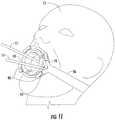
- FIG. 1shows a person 15 with an oral apparatus 10 positioned inside their mouth for maintaining their mouth open.
- the oral apparatus 10can be useful in dental or medical procedures to allow medical instruments to pass into a person's mouth. During such procedures, the person may accidentally close their mouth, biting down on the instruments, thereby causing pain and/or injury to the person and possible damage to the medical instruments.
- the oral apparatus 10is useful in maintaining the person's mouth in an open position and preventing that person from biting down during the procedure.
- the oral apparatus 10fits within a person's mouth 16, inbetween their upper jaw and the lower jaw, and may rest on the person's teeth 18 (and/or gums).
- the oral apparatus 10forces the upper and lower jaw apart so as to maintain the person's mouth 16 in the open position.
- the oral apparatus 10is a bite block comprising at least one band that is curved. When connected, the band forms a closed loop with an opening 14 defined therethrough.
- the opening 14may be large enough to allow medical instruments 12 to pass through it into the person's mouth 16 for performing a dental or medical procedure therein.
- the oral apparatus 10may be adjustable such that the closed loop of the band adjusts to different radial dimensions, corresponding to different sizes in the opening 14.
- the oral apparatus 10may adjust to fit small or larger size mouths, as well as adjusting to fit differently sized medical instruments 12 that need to pass through the opening 14.
- the oral apparatus 10may be maneuvered into a different position in a person's mouth 16 to allow access into different portions of the person's mouth 16. For example, the oral apparatus 10 may be shifted to the left side of a person's mouth 16 to allow access for instruments 12 through the opening 14 to a person's right side of their mouth 16.
- FIG. 2shows one embodiment of an adjustable bite block that incorporates a pull-snap mechanism.
- the adjustable bite block 20comprises a band 25 that closes to form a generally annular shaped loop defining an opening 24.
- the band 25When separated, the band 25, as shown in FIG. 3 , is one elongated piece of curved material comprising a first end 27 and a second end 28. The first and second end 27, 28 are configured to be coupled to one another so as to define a closed loop (shown in FIG. 2 ) with the opening 24 defined therethrough.
- the band 25comprises at least two tabs 30 and a receiving feature 32. The tabs 30 protrude from the band 25 near the first end 27 and are configured to engage with or "snap" into the receiving feature 32, which is located near the second end 28.
- the band 25forms a closed loop (shown in FIG. 5 ).
- the adjustable bite block 20With the band 25 in a closed loop, the adjustable bite block 20 can be placed into a person's mouth to hold the person's upper jaw and lower jaw open.
- the bandmay comprise plastic material.
- the first and second ends 27, 28 of the band 25are also configured to be selectively adjusted relative to one another to adjust a radial dimension of the closed loop.
- the band 25 of the adjustable bite block 20comprises at least two tabs 30.
- the tabs 30are spaced at different distances along the band 25 near the first end 27.
- the different distances of the tabs 30 along the band 25correspond to different radial sizes of the closed loop and the opening 24.
- the greater the distance between the tab 30 and the first end 27, the smaller the closed loop and opening 24will be when the receiving feature 32 near the second end 28 engages with that tab 30.
- the band 25may comprise more than two tabs (e.g., 3, 4, 8), and the number of tabs may correspond to the number of possible sizes of the closed loop. Additionally, the band 25 may comprise more than one receiving feature 32. For example, as shown in FIG. 3 , the portion of the band 25 near the second end 28 may have receiving features 32 equal to the number of tabs 30 such that when the closed loop is the smallest radial dimension, all of the receiving features 32 engage individually with all of the tabs 30.
- the band 25comprises an interior side 21 facing inward and an exterior side 22 facing outward.
- the tabs 30are located on the interior side 21 of the band 25.
- the adjustable bite block 20can be adjusted to fit the size of the person's mouth or the size of the medical instrument.
- indicators 38can be placed on the band 25 to indicate to a user the size of the radial dimension being created. As shown in FIG. 5A , indicators 38 may be etches in the band 25 such as numbers or marks and may even correspond to mouth sizes for patients, such as 48Fr, 60Fr, 64Fr, 68Fr, 72Fr, or the like. Other measurement markers may also be used, such as diameter measurements. For example, in some embodiments, measurements indicating the minimum length required for an opening large enough for use of instruments may be indicated on the band.
- the oral apparatusmay also include flanges or walls 80 configured to hold or hug a person's teeth to help maintain the oral apparatus 10 in the person's mouth.
- the first band 25 of the adjustable bite block 20may comprise at least one wall 80 that protrudes from the band 25.
- two walls 80protrude from the exterior side 22 of the band 25 near the edges of the band 25 such that a gap or floor 82 exists between them.
- Such a configuration along the band 25allows for a person's teeth to rest between the walls 80 on the floor 82.
- the walls 80 or floor 82may comprise cushioned material to provide comfort or protection for the person's mouth or teeth.
- the wall 80may extend any length along a portion of the band 25 up to the length of the exterior side 22 of the band 25 that corresponds to the smallest radial dimension. For example, with reference to FIG. 4 , a portion of the second end 28 of the band 25 lays underneath a portion of the first end 27 of the band 25. Since the wall 80 protrudes from the exterior side 22 of the band 25, the wall 80 may only extend up to a point 84 which marks the end of the portion of the band 25 that will not be overlapped by the first end 27 of the band 25.
- a band 25 configured with the walls 80 extending to the point 84, as shown in FIG. 2allows for most of the exterior side 22 of the band 25 to be covered by the walls 80, thereby ensuring maximum protection for keeping the adjustable bite block 20 from falling out of the person's mouth.
- FIG. 6shows another embodiment of an adjustable bite block that incorporates a pull-ratchet mechanism.
- the adjustable bite block 40comprises a first band 55 and a second band 65 that connect to form a closed loop defining an opening 44.
- the first band 55shown separate in FIG. 7 , is an elongated piece of curved material comprising a first end 57 and a second end 59.
- the second band 65also is an elongated piece of curved material comprising a first end 67 and a second end 69.
- the first and second bands 55, 65each form general U-shapes.
- the first and second bandsmay each comprise plastic material.
- the first band 55comprises an insert 53 located on a portion of the first band 55 near the first end 57.
- the second band 65defines a slot 66 located at its second end 69 and configured to receive the insert 53 of the first band 55.
- the second band 65may further comprise an insert 63 on a portion near the first end 67 of the second band 65 and the first band 55 may further define a slot 56 located at its second end 59 and configured to receive the insert 63 of the second band 65.
- the insert 63 of the second band 65may comprise ratchet teeth 61.
- the first band 55may comprise ratchet receiving teeth 62 located near the second end 59 of the first band 55 and configured to engage with the ratchet teeth 61.
- the first band 55may be configured to receive the insert 63 of the second band 65 through the slot 56 such that the ratchet teeth 61 on the insert 63 of the second band 65 engage with ratchet receiving teeth 62 of the first band 55.
- the second band 65may also comprise ratchet receiving teeth 62 located near the second end 69 and configured to engage with ratchet teeth 61 on the insert 53 of the first band 55.
- the second band 65may also be configured to receive the insert 53 of the first band 55 through the slot 66 such that the ratchet teeth 61 on the insert 53 of the first band 55 engage with ratchet receiving teeth 62 of the second band 65.
- the insert 53 of the first band 55is configured to insert into the slot 66 of the second band 65. Additionally, in the depicted embodiment, the insert 63 of the second band 65 is also configured to insert into the slot 56 of the first band 55.
- a userconnects the first and second bands 55, 65 by placing the inserts 53, 63 into the slots 56, 66 and engaging the ratchet teeth 61 with the ratchet receiving teeth 62 (shown in FIG. 8B , which is a cross-sectional view taken along line 8B in FIG. 6 ).
- the adjustable bite block 40when connected, can form different radial dimensions for the closed loop and the opening 44.
- each individual ratchet tooth 61may be located at different distances along the inserts 53, 63 such that connection of different ratchet tooth 61 to the ratchet receiving teeth 62 corresponds to different radial dimensions of the closed loop and opening 44.
- the first and second bands 55, 65may include any number of ratchet teeth 61 or ratchet receiving teeth 62, which may correspond to many different radial dimensions of the closed loop and opening 44.
- the ratchet teeth 61may be tapered to allow the loop to be expanded without allowing further insertion of the inserts 53, 63 or contraction of the radial dimension of the loop.
- the ratchet receiving teeth 62may also comprise a similar taper. Such a taper allows a user to connect the first and second bands 55, 65 to create the smallest radial dimension loop and then adjust it by expanding the loop to the desired radial dimension.
- the above described taperprevents contraction of the loop or opening 44, thereby preventing a person with the adjustable bite block 40 inserted in their mouth from biting down and altering the radial dimension.
- Tapers to ratchetssuch as those described above, are known in the art for ratchet type designs.
- indicators 48can be placed on the inserts 53, 63 of the bands 55, 65 to indicate to a user the size of the radial dimension being created. As seen in FIG. 9 , indicators 48 may be etches in the bands 55, 65 or inserts 53, 63 such as numbers or marks and may even correspond to mouth sizes for patients, such as 48Fr, 60Fr, 64Fr, 68Fr, 72Fr, or the like. Other measurements markers may also be used, such as diameter measurements.
- the adjustable bite block 40may also comprise at least one wall 80 for keeping the adjustable bite block 40 in a person's mouth.
- the first and second bands 55, 65may comprise at least one flange or wall 80 protruding from generally exterior sides 91, 92, respectively.
- the walls 80may extend along the length of each first and second band 55, 65 from the second end 59, 69 to the beginning of the insert 53, 63. As such, when the adjustable bite block 40 is formed into its smallest radial dimension, the ends of the walls 80 are adjacent to each other such that they form a closed loop.
- the first and second bands 55, 65each comprise two walls 80 located near the edges of the bands such that a gap or floor 82 exists between them for a person's gums or teeth to rest on.
- the walls 80 or floor 82may comprise cushioned material to provide comfort or protection for the person's mouth or teeth.
- the flanges or walls 80may include indentations or slots for medical instruments to pass through.
- indentations or slotswould allow additional instruments, like a suction tube, to pass into a person's mouth without taking up space in the opening 14 created by the oral apparatus 10.
- some embodiments of the present inventioncontemplate other configurations for an oral appliance for maintaining a person's mouth open.
- some embodiments of the present inventioncontemplate other configurations for an adjustable bite block. Examples of some other contemplated adjustable bite blocks are illustrated in FIGs. 16 , 16A , 17 , 17A , 18 , 18A , 18B , 19 , and 19A .
- FIG. 16shows another example embodiment of an adjustable bite block that incorporates a ratchet mechanism.
- the adjustable bite block 240comprises a first band 255 and a second band 265 that connect to form a closed loop defining an opening 244.
- the first band 255is an elongated piece of curved material comprising a first end 257 and a second end 259.
- the first band 255further defines an interior wall portion 258 near the second end 259.
- the second band 265also is an elongated piece of curved material comprising a first end 267 and a second end 269.
- the second band 265defines an interior wall portion 268 near the second end 269.
- the first and second bands 255, 265each form general U-shapes.
- the first and second bandsmay each comprise plastic material.
- the adjustable bite block 240may also comprise at least one wall 280 for keeping the adjustable bite block 240 in a person's mouth.
- the first end 257 of the first band 255may define one or more ratchet teeth 281. Additionally, the interior wall portion 258 of the first band 255 may comprise ratchet receiving teeth 282. Similarly, the first end 267 of the second band 265 may define one or more ratchet teeth 291. Additionally, the interior wall portion 268 of the second band 265 may comprise ratchet receiving teeth 292.
- the second end 259 and the interior wall portion 258 of the first band 255may be configured to receive the first end 267 of the second band 265 such that the ratchet teeth 291 of the second band 265 engage with ratchet receiving teeth 282 of the first band 255.
- the second end 269 and the interior wall portion 268 of the second band 265may be configured to receive the first end 257 of the first band 255 such that the ratchet teeth 281 of the first band 255 engage with ratchet receiving teeth 292 of the second band 265.
- the adjustable bite block 240when connected, can form different radial dimensions for the closed loop and the opening 244.
- each the ratchet receiving teeth 282, 292may each receive different ratchet teeth 281, 291 so as to define different radial dimensions of the closed loop and opening 244.
- a usermay squeeze the second ends 259, 269 of the first and second bands 255, 265 in the horizontal direction (e.g., along arrows AA).
- the ratchet teeth 281, 291 and the corresponding ratchet receiving teeth 282, 292may disengage and become spaced apart so as to enable relative vertical movement (and, thus, resizing of the loop).
- the ratchet teeth 281, 291 and corresponding ratchet receiving teeth 282, 292are designed with a taper to prevent adjustment from pressure in the vertical direction.
- FIG. 17shows another example embodiment of an adjustable bite block that incorporates an interference fit and hinge mechanism.
- the adjustable bite block 300comprises a first band 355 and a second band 365 that connect to form a closed loop defining an opening 344.
- the first band 355is an elongated piece of curved material comprising a first end 357 and a second end 359.
- the second band 365also is an elongated piece of curved material comprising a first end 367 and a second end 369.
- the second end 359 of the first band 355 and the second end 369 of the second band 365are hingedly connected at a hinge 315 that enables rotation of the second band 365 relative to the first band 355.
- the first and second bands 355, 365each form general U-shapes.
- the first and second bandsmay each comprise plastic material.
- the adjustable bite block 300may also comprise at least one wall 380 for keeping the adjustable bite block 300 in a person's mouth.
- the second band 365may define one or more protrusions 371 on a surface of the first end 367 facing the interior surface of the first end 357 of the first band 355.
- the first end 357 of the first band 355may comprise at least one slot 341 configured to securely receive one of the protrusions 371 of the second band 365.
- the second band 365may be rotated relative to the first band 355 such that a different protrusion 371 securely engages with the slot 341 of the first band 355.
- a usercould rotate the second band 365 downwardly to securely engaging a different protrusion 371a with the slot 341.
- additional space 342may be defined within the first end 357 of the first band 355 to enable rotation of the second band 365. In such a manner, a user may define the radial dimension of the loop and the opening 344 of the adjustable bite block 300.
- FIG. 18shows another example embodiment of an adjustable bite block that incorporates a cam and hinge mechanism.
- the adjustable bite block 400comprises a first band 455 and a second band 465 that connect to form a closed loop defining an opening 444.
- the first band 455is an elongated piece of curved material comprising a first end 457 and a second end 459.
- the second band 465also is an elongated piece of curved material comprising a first end 467 and a second end 469.
- the second end 459 of the first band 455 and the second end 469 of the second band 465are hingedly connected at a hinge 415 that enables rotation of the second band 465 relative to the first band 455.
- the first and second bands 455, 465each form general U-shapes.
- the first and second bandsmay each comprise plastic material.
- the adjustable bite block 400may also comprise at least one wall 480 for keeping the adjustable bite block 400 in a person's mouth.
- the first band 455may define a knob 445 near the first end 457.
- the knob 445is configured to rotate relative to the first band 455.
- the knob 445may include a tab 447 that engages with an elongated slot 449 defined in the second band 465 near the first end 367 of the second band 465.
- the knob 445may be rotated such that the tab 447 travels within the elongated slot 449 and forces the first end 469 of the second band 465 to move vertically relative to the first band 455.
- a usercould rotate the knob 445 clockwise to force the tab 447 (and, thus, the elongated slot 449) to travel upwardly.
- Such a motionwould also cause the second band 465 to rotate upwardly.
- the radial dimension of the loop and openingwould enlarge.
- a portion 478 of the second band 465may be defined differently, such as to form a different shape (e.g., other than a U-shape).
- the second band 465may define different shapes so as to provide for increased comfort within a user's mouth.
- the shape of the second band 465may define a bottom half of a hexagon. In such an embodiment, as the second band 465 is rotated relative to the first band 455, there may be more than one straight edge available to align with the bottom of the user's mouth.
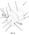
- FIG. 19shows another example embodiment of an adjustable bite block that incorporates a shelving-type, interference fit mechanism.
- the adjustable bite block 500comprises a first band 555 and a second band 565 that connect to form a closed loop defining an opening 544.
- the first band 555is an elongated piece of curved material comprising a first end 557 and a second end 559.
- the second band 565also is an elongated piece of curved material comprising a first end 567 and a second end 569.
- the first and second bands 555, 565each form general U-shapes.
- the first and second bandsmay each comprise plastic material.
- the adjustable bite block 500may also comprise at least one wall 580 for keeping the adjustable bite block 500 in a person's mouth.
- the first band 555may comprise at least two slots 541 positioned near the first end 557 and the second end 559. Additionally, in order to enable connection of the first band 555 and the second band 565, the second band 565 may define one or more protrusions 581 near the first end 567 and the second 569 that are configured to securely engage with one or more of the corresponding slots 541 of the first band 555.
- the second band 565may be slide out of engagement with the first band 555 (e.g., along arrow BB). Then, depending on the desired radial dimension of the loop and opening 544, each protrusion 581 may be aligned with and slid into a corresponding slot 541. For example, the two protrusions 581 on each end of the second band 565 may be aligned (and then engaged) with the top two slots 541a, 541b in order to define a smaller opening 544 than that shown in FIG. 19 .
- each slot 541 of the first band 555may define an end stop 579 that prevents the protrusion 581 from being slid too far within the slot 541. Additionally or alternatively, in some embodiments, the cross-section 578 of each slot 541 may decrease from the front 577 to the back 576. In such a manner, a user may feel resistance as the protrusion 581 is slid along the slot 541, thereby further enhancing the interference fit of the protrusion 581 and slot 541.
- FIG. 10illustrates another example, wherein the oral apparatus 10 is configured to couple to a flexible strap 95 for holding the oral apparatus 10 in the person's mouth 16.
- Various embodiments of the oral apparatus 10, including previously described adjustable bite blocks 20, 40may include at least one connector 90 protruding from the oral apparatus 10 and configured to couple to a strap 95.
- the oral apparatus 10includes two radially opposite connectors 90 that are coupled to a strap 95 that is passed around the head of a person 15.
- another embodiment of the oral apparatus 10includes four connectors 90 spaced along the oral apparatus 10 to couple to a Y-shaped strap 96.
- the Y-shaped strap 96is one flexible strap that forks into a "Y" before coupling to the connectors 90 on the oral apparatus 10.
- the "Y”allows for additional space 97 between the two forked straps coupled to the connectors 90 on the oral apparatus 10.
- the additional space 97can be used to pass additional medical instruments 11', such as suction tubes, into the person's mouth 16 without utilizing the opening 14 created by the closed loop of the oral apparatus 10.
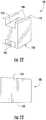
- FIG. 12shows another embodiment of an oral apparatus for maintaining a person's mouth open, wherein the oral apparatus is a wedge bite block.
- the wedge bite block 100comprises an upper surface 110 and a lower surface 120.
- the upper surface 110 and lower surface 120may be configured along differently angled planes so as to form a general wedge shape.
- the lower surface 120lies along a flat plane in comparison to the slightly downward sloping plane of the upper surface 110 of the wedge bite block 100 (as shown in FIG. 13 ).
- the wedge bite block 100may also comprise at least one wedge wall 180.
- the wedge wall 180protrudes from the upper or lower surface 110, 120 and is designed to engage with and lie adjacent to a person's teeth to maintain the wedge bite block 100 in place.
- the upper surface 110comprises two walls 180 located near the edges of the upper surface 110 so as to create a gap or upper slot 115 between the walls 180 for fitting a person's upper gums or teeth.
- the lower surface 120also comprises two walls 180 spaced near the edges to create a lower slot 125 to engage and fit a person's lower gums or teeth.
- the wedge bite block 100can be inserted into a person's mouth to prop open and maintain open their mouth.
- the wedge bite block 100can be placed between a person's upper and lower teeth.
- the slight downward angle of the plane of the upper surface 110will correspond to the angle at which a person's mouth will be maintained open.
- the wedge bite block 100can be inserted further into a person's mouth or the slope of the upper surface 110 can be increased.
- the plane of the lower surface 120can be given a slope in order to increase or decrease the angle at which a person's mouth is held open.
- a wedge bite block 100may comprise a handle 130.
- the handle 130protrudes from the wedge bite block 100 toward the outside of a person's mouth and is configured to allow a user (e.g., doctor, nurse, patient, etc.) to easily place and position the wedge bite block 100 in a person's mouth.
- the handle 130also ensures that the user, who is placing the wedge bite block 100 into a person's mouth, will not accidentally or otherwise be harmed if the person bites down while the wedge bite block 100 is being placed into the person's mouth.
- the handle 130may comprise a grip 135 configured to allow a user to easily grab the handle 130.
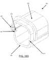
- FIG. 15shows another embodiment of an oral apparatus for maintaining a person's mouth open, wherein the oral apparatus comprises two wedge bite blocks 100, 100'.
- the dual wedge bite block 200comprises two wedge bite blocks 100, 100' configured to fit on either side of a person's mouth to maintain that person's mouth in the open position.
- the dual wedge bite block 200also comprises a connection band 140 connecting the individual wedge bite blocks 100, 100'.
- one or both of the wedge bite blocks 100, 100'may also comprise a handle 130 for easy placement and positioning of the dual wedge bite block 200. Also disclosed is a method for positioning an oral apparatus, such as any of the previously described apparatus embodiments, within a person's mouth.
- the methodcomprises providing at least one band of curved material comprising a first portion and a second portion, coupling the first and second portions to one another so as to define a closed loop with an opening defined therethrough, and positioning the bite block within a person's mouth such that at least a portion of the loop engages the person's teeth to maintain the person's mouth in an open position.
- the methodmay further comprise adjusting the first and second portions relative to one another so as to adjust a radial dimension of the loop prior to the coupling step.
- the methodmay also further comprise inserting an instrument through the opening defined in the loop while the bite block is positioned within the person's mouth.
Landscapes
- Health & Medical Sciences (AREA)
- Life Sciences & Earth Sciences (AREA)
- Surgery (AREA)
- Veterinary Medicine (AREA)
- Public Health (AREA)
- General Health & Medical Sciences (AREA)
- Animal Behavior & Ethology (AREA)
- Heart & Thoracic Surgery (AREA)
- Biomedical Technology (AREA)
- Engineering & Computer Science (AREA)
- Medical Informatics (AREA)
- Radiology & Medical Imaging (AREA)
- Pathology (AREA)
- Optics & Photonics (AREA)
- Nuclear Medicine, Radiotherapy & Molecular Imaging (AREA)
- Molecular Biology (AREA)
- Biophysics (AREA)
- Physics & Mathematics (AREA)
- Pulmonology (AREA)
- Dentistry (AREA)
- Oral & Maxillofacial Surgery (AREA)
- Otolaryngology (AREA)
- Emergency Medicine (AREA)
- Anesthesiology (AREA)
- Hematology (AREA)
- Epidemiology (AREA)
- Orthopedics, Nursing, And Contraception (AREA)
- Dental Tools And Instruments Or Auxiliary Dental Instruments (AREA)
- Helmets And Other Head Coverings (AREA)
Description
- Embodiments of the present invention discussed herein are related to an oral apparatus for dentistry and other medical procedures, and more particularly to an oral apparatus for maintaining a person's mouth open during such dentistry and medical procedures.
- Often, dental and medical procedures, like endoscopy, require medical instruments to be passed orally, through a person's mouth. Some patient's may accidentally or otherwise close their mouths during the procedure which can harm the patient or ruin the medical instrument. In order to maintain a person's mouth open during a procedure, often an oral apparatus is placed in the person's mouth. However, many patients have different size mouths, and the oral apparatus placed in the person's mouth may be uncomfortable or difficult for the doctor to work around with the medical instrument. Therefore, improvements are needed so that an oral apparatus will fit properly in different size mouths and provide proper exposure for medical instruments to be passed orally.
US 5,069,206 discloses a device according to the preamble ofclaim 1.- The invention provides an adjustable bite block as defined by
claim 1. - Having thus described the invention in general terms, reference will now be made to the accompanying drawings, which are not necessarily drawn to scale. Some of the devices shown in the drawings are not part of the invention and represent examples of similar devices not falling within the scope of the claims.
FIG. 1 is a perspective view illustrating an oral apparatus inserted into a person's mouth for maintaining their mouth in an open position, wherein instruments are being passed through the oral apparatus into the person's mouth, according to some examples;FIG. 2 is a perspective view of the oral appliance onFIG. 1 , wherein the oral appliance is an adjustable bite block, according to an example;FIG. 3 is a perspective view of the adjustable bite block shown inFIG. 2 disposed in a disconnected configuration, according to an example;FIG. 4 is a side view of the adjustable bite block shown inFIG. 2 disposed in a disconnected configuration, according to an example;FIG. 5 is a side view of the adjustable bite block shown inFIG. 2 disposed in a connected configuration, according to an example;FIG. 5A is a detail view of a portion of the adjustable bite block shown inFIG. 5 , wherein the radial dimension of the adjustable bite block in the connected position is indicated, according to an example;FIG. 6 is a perspective view of an oral appliance for maintaining a person's mouth in the open position, wherein the oral appliance is an adjustable bite block, according to an example;FIG. 7 is a perspective view of the adjustable bite block shown inFIG. 6 disposed in a disconnected configuration, according to an example;FIG. 8A is a detailed cross-sectional view taken alongline 8A inFIG. 7 of the adjustable bite block shown inFIG 6 , wherein the adjustable bite block is disposed in a disconnected configuration, according to an example;FIG. 8B is a detailed cross-sectional view taken alongline 8B inFIG. 6 of the adjustable bite block shown inFIG 6 , wherein the adjustable bite block is disposed in a connected configuration, according to an example; andFIG. 9 is a detail view of a portion of the adjustable bite block shown inFIG. 7 , wherein indicators of the radial dimension of the adjustable bite block are illustrated, according to some examples;FIG. 10 is a perspective view of an oral apparatus inserted into a person's mouth, wherein a strap is coupled to the oral apparatus, according to some some examples;FIG. 11 is a perspective view of an oral apparatus inserted into a person's mouth, wherein a "Y" shaped strap is coupled to the oral apparatus, according to some examples;FIG. 12 is a perspective view of an oral appliance for maintaining a person's mouth in the open position, wherein the oral appliance is a wedge bite block, according to an example;FIG. 13 is a side view of the wedge bite block shown inFIG. 12 , according to an example;FIG. 14 is a perspective view of a wedge bite block, wherein a handle extends from the wedge bite block, according to an example;FIG. 15 is a perspective view of a dual wedge bite block, according to an example;FIG. 16 is a perspective view of another example oral appliance for maintaining a person's mouth in an open position, wherein the oral appliance is an adjustable bite block;FIG. 16A is a perspective view of a cross-section of the oral appliance shown inFIG. 16 taken alongline 16A, according to some examples;FIG. 17 is a perspective view of yet another example oral appliance for maintaining a person's mouth in an open position, wherein the oral appliance is an adjustable bite block, according to some example embodiments of the present invention;FIG. 17A is a front view of a cross-section of the oral appliance shown inFIG. 17 taken alongline 17A, according to some example embodiments of the present invention;FIG. 18 is a perspective view of yet another example oral appliance for maintaining a person's mouth in an open position, wherein the oral appliance is an adjustable bite block, according to some examples;FIG. 18A is a front view of the oral appliance shown inFIG. 18 , according to some examples;FIG. 18B is a perspective view of a cross-section of the oral appliance shown inFIG. 18 taken alongline 18B, according to some examples;FIG. 19 is a perspective view of another example oral appliance for maintaining a person's mouth in an open position, wherein the oral appliance is an adjustable bite block, according to some example embodiments of the present invention; andFIG. 19A is a perspective view of a top band of the oral appliance shown inFIG. 19 , according to some example embodiments of the present invention.- The present invention now will be described more fully hereinafter with reference to the accompanying drawings, in which some, but not all embodiments of the inventions are shown. Indeed, these inventions may be embodied in many different forms and should not be construed as limited to the embodiments set forth herein; rather, these embodiments are provided so that this disclosure will satisfy applicable legal requirements. Like numbers refer to like elements throughout.
FIG. 1 shows aperson 15 with anoral apparatus 10 positioned inside their mouth for maintaining their mouth open. Theoral apparatus 10 can be useful in dental or medical procedures to allow medical instruments to pass into a person's mouth. During such procedures, the person may accidentally close their mouth, biting down on the instruments, thereby causing pain and/or injury to the person and possible damage to the medical instruments. Thus, theoral apparatus 10 is useful in maintaining the person's mouth in an open position and preventing that person from biting down during the procedure.- According to various embodiments, as shown in
FIG. 1 , theoral apparatus 10 fits within a person'smouth 16, inbetween their upper jaw and the lower jaw, and may rest on the person's teeth 18 (and/or gums). Theoral apparatus 10 forces the upper and lower jaw apart so as to maintain the person'smouth 16 in the open position. In the depicted embodiment, theoral apparatus 10 is a bite block comprising at least one band that is curved. When connected, the band forms a closed loop with an opening 14 defined therethrough. The opening 14 may be large enough to allowmedical instruments 12 to pass through it into the person'smouth 16 for performing a dental or medical procedure therein. - Additionally, as described in greater detail below with respect to specific embodiments, the
oral apparatus 10 may be adjustable such that the closed loop of the band adjusts to different radial dimensions, corresponding to different sizes in theopening 14. Thus, theoral apparatus 10 may adjust to fit small or larger size mouths, as well as adjusting to fit differently sizedmedical instruments 12 that need to pass through theopening 14. Moreover, theoral apparatus 10 may be maneuvered into a different position in a person'smouth 16 to allow access into different portions of the person'smouth 16. For example, theoral apparatus 10 may be shifted to the left side of a person'smouth 16 to allow access forinstruments 12 through the opening 14 to a person's right side of theirmouth 16. FIG. 2 shows one embodiment of an adjustable bite block that incorporates a pull-snap mechanism. In the depicted embodiment, theadjustable bite block 20 comprises aband 25 that closes to form a generally annular shaped loop defining anopening 24.- When separated, the
band 25, as shown inFIG. 3 , is one elongated piece of curved material comprising afirst end 27 and asecond end 28. The first andsecond end FIG. 2 ) with theopening 24 defined therethrough. In the depicted embodiment, theband 25 comprises at least twotabs 30 and a receivingfeature 32. Thetabs 30 protrude from theband 25 near thefirst end 27 and are configured to engage with or "snap" into the receivingfeature 32, which is located near thesecond end 28. Thus, when the receivingfeature 32 engages with at least onetab 30, theband 25 forms a closed loop (shown inFIG. 5 ). With theband 25 in a closed loop, theadjustable bite block 20 can be placed into a person's mouth to hold the person's upper jaw and lower jaw open. In some embodiments, the band may comprise plastic material. - Additionally, the first and second ends 27, 28 of the
band 25 are also configured to be selectively adjusted relative to one another to adjust a radial dimension of the closed loop. In the depicted embodiments ofFIGS. 3-5 , theband 25 of theadjustable bite block 20 comprises at least twotabs 30. Thetabs 30 are spaced at different distances along theband 25 near thefirst end 27. The different distances of thetabs 30 along theband 25 correspond to different radial sizes of the closed loop and theopening 24. The greater the distance between thetab 30 and thefirst end 27, the smaller the closed loop andopening 24 will be when the receivingfeature 32 near thesecond end 28 engages with thattab 30. Furthermore, the greater the overlap between the portion of theband 25 near thefirst end 27 and the portion of theband 25 near thesecond end 28, the smaller the closed loop. - As will be apparent to one of ordinary skill in the art, the
band 25 may comprise more than two tabs (e.g., 3, 4, 8), and the number of tabs may correspond to the number of possible sizes of the closed loop. Additionally, theband 25 may comprise more than one receivingfeature 32. For example, as shown inFIG. 3 , the portion of theband 25 near thesecond end 28 may have receivingfeatures 32 equal to the number oftabs 30 such that when the closed loop is the smallest radial dimension, all of the receiving features 32 engage individually with all of thetabs 30. - With reference to
FIGS. 3-5 , to connect the first and second ends 27, 28 of theband 25 and close the loop, a user can connect or snap the receivingfeature 32 over thetab 30. When in a closed loop, theband 25 comprises aninterior side 21 facing inward and anexterior side 22 facing outward. In the depicted embodiment, thetabs 30 are located on theinterior side 21 of theband 25. Thus, to connect thetabs 30 and receivingfeature 32, a user passes thesecond end 28 of theband 25 under thefirst end 27 of theband 25 such that at least a portion of the portion of thefirst end 27 and at least a portion of the portion of thesecond end 28 overlap. - Once the
band 25 is formed in a closed loop with at least one receivingfeature 32 engaged with at least onetab 30, a user can disengage the receivingfeature 32 and resize theband 25. The user may pull thesecond end 28 of theband 25 away from thetabs 30 until the receivingfeature 32 disengages with thetab 30. The receivingfeature 32 near thesecond end 28 can then be placed onto or snapped into adifferent tab 30, such that the closed loop andopening 24 are re-sized to the desired radial dimension. In this way, theadjustable bite block 20 can be adjusted to fit the size of the person's mouth or the size of the medical instrument. - To aid in determining the correct radial dimension of the
adjustable bite block 20,indicators 38 can be placed on theband 25 to indicate to a user the size of the radial dimension being created. As shown inFIG. 5A ,indicators 38 may be etches in theband 25 such as numbers or marks and may even correspond to mouth sizes for patients, such as 48Fr, 60Fr, 64Fr, 68Fr, 72Fr, or the like. Other measurement markers may also be used, such as diameter measurements. For example, in some embodiments, measurements indicating the minimum length required for an opening large enough for use of instruments may be indicated on the band. - Various embodiments of the oral apparatus may also include flanges or
walls 80 configured to hold or hug a person's teeth to help maintain theoral apparatus 10 in the person's mouth. As shown inFIG. 3 , thefirst band 25 of theadjustable bite block 20 may comprise at least onewall 80 that protrudes from theband 25. In the depicted embodiment, twowalls 80 protrude from theexterior side 22 of theband 25 near the edges of theband 25 such that a gap orfloor 82 exists between them. Such a configuration along theband 25 allows for a person's teeth to rest between thewalls 80 on thefloor 82. In other embodiments, thewalls 80 orfloor 82 may comprise cushioned material to provide comfort or protection for the person's mouth or teeth. - The
wall 80 may extend any length along a portion of theband 25 up to the length of theexterior side 22 of theband 25 that corresponds to the smallest radial dimension. For example, with reference toFIG. 4 , a portion of thesecond end 28 of theband 25 lays underneath a portion of thefirst end 27 of theband 25. Since thewall 80 protrudes from theexterior side 22 of theband 25, thewall 80 may only extend up to apoint 84 which marks the end of the portion of theband 25 that will not be overlapped by thefirst end 27 of theband 25. Aband 25 configured with thewalls 80 extending to thepoint 84, as shown inFIG. 2 , allows for most of theexterior side 22 of theband 25 to be covered by thewalls 80, thereby ensuring maximum protection for keeping theadjustable bite block 20 from falling out of the person's mouth. FIG. 6 shows another embodiment of an adjustable bite block that incorporates a pull-ratchet mechanism. In the depicted embodiment, theadjustable bite block 40 comprises afirst band 55 and asecond band 65 that connect to form a closed loop defining anopening 44. Thefirst band 55, shown separate inFIG. 7 , is an elongated piece of curved material comprising afirst end 57 and asecond end 59. Thesecond band 65 also is an elongated piece of curved material comprising afirst end 67 and asecond end 69. In the depicted embodiment, the first andsecond bands - The
first band 55 comprises aninsert 53 located on a portion of thefirst band 55 near thefirst end 57. Thesecond band 65 defines aslot 66 located at itssecond end 69 and configured to receive theinsert 53 of thefirst band 55. In some embodiments, thesecond band 65 may further comprise aninsert 63 on a portion near thefirst end 67 of thesecond band 65 and thefirst band 55 may further define aslot 56 located at itssecond end 59 and configured to receive theinsert 63 of thesecond band 65. - With reference to
FIG. 8A , which shows a cross-sectional view taken alongline 8A inFIG. 7 , theinsert 63 of thesecond band 65 may comprise ratchetteeth 61. Additionally, thefirst band 55 may compriseratchet receiving teeth 62 located near thesecond end 59 of thefirst band 55 and configured to engage with theratchet teeth 61. Furthermore, thefirst band 55 may be configured to receive theinsert 63 of thesecond band 65 through theslot 56 such that theratchet teeth 61 on theinsert 63 of thesecond band 65 engage withratchet receiving teeth 62 of thefirst band 55. In various embodiments, thesecond band 65 may also compriseratchet receiving teeth 62 located near thesecond end 69 and configured to engage withratchet teeth 61 on theinsert 53 of thefirst band 55. Thesecond band 65 may also be configured to receive theinsert 53 of thefirst band 55 through theslot 66 such that theratchet teeth 61 on theinsert 53 of thefirst band 55 engage withratchet receiving teeth 62 of thesecond band 65. - With reference to
FIG. 7 , theinsert 53 of thefirst band 55 is configured to insert into theslot 66 of thesecond band 65. Additionally, in the depicted embodiment, theinsert 63 of thesecond band 65 is also configured to insert into theslot 56 of thefirst band 55. To close the loop, a user connects the first andsecond bands inserts slots ratchet teeth 61 with the ratchet receiving teeth 62 (shown inFIG. 8B , which is a cross-sectional view taken alongline 8B inFIG. 6 ). - The
adjustable bite block 40, when connected, can form different radial dimensions for the closed loop and theopening 44. For example, as shown in the depicted embodiment ofFIG. 7 , eachindividual ratchet tooth 61 may be located at different distances along theinserts different ratchet tooth 61 to theratchet receiving teeth 62 corresponds to different radial dimensions of the closed loop andopening 44. The smaller the distance between theindividual ratchet teeth 61 and thefirst end second bands opening 44 will be when theratchet receiving feature 62 engages with theindividual ratchet teeth 61. As will be apparent to one of skill in the art, the first andsecond bands ratchet teeth 61 or ratchet receivingteeth 62, which may correspond to many different radial dimensions of the closed loop andopening 44. - Additionally, once the first and
second bands opening 44. In depicted embodiments, theratchet teeth 61 may be tapered to allow the loop to be expanded without allowing further insertion of theinserts ratchet receiving teeth 62 may also comprise a similar taper. Such a taper allows a user to connect the first andsecond bands opening 44, thereby preventing a person with theadjustable bite block 40 inserted in their mouth from biting down and altering the radial dimension. Tapers to ratchets, such as those described above, are known in the art for ratchet type designs. - To aid in determining the correct radial dimension of the
adjustable bite block 40,indicators 48 can be placed on theinserts bands FIG. 9 ,indicators 48 may be etches in thebands - As shown in
FIGS. 6 and7 , theadjustable bite block 40 may also comprise at least onewall 80 for keeping theadjustable bite block 40 in a person's mouth. The first andsecond bands wall 80 protruding from generallyexterior sides walls 80 may extend along the length of each first andsecond band second end insert adjustable bite block 40 is formed into its smallest radial dimension, the ends of thewalls 80 are adjacent to each other such that they form a closed loop. In the depicted embodiment, the first andsecond bands walls 80 located near the edges of the bands such that a gap orfloor 82 exists between them for a person's gums or teeth to rest on. In some embodiments, thewalls 80 orfloor 82 may comprise cushioned material to provide comfort or protection for the person's mouth or teeth. - In other various embodiments, the flanges or
walls 80 may include indentations or slots for medical instruments to pass through. For example, such indentations or slots would allow additional instruments, like a suction tube, to pass into a person's mouth without taking up space in theopening 14 created by theoral apparatus 10. - As noted herein, some embodiments of the present invention contemplate other configurations for an oral appliance for maintaining a person's mouth open. Along these lines, some embodiments of the present invention contemplate other configurations for an adjustable bite block. Examples of some other contemplated adjustable bite blocks are illustrated in
FIGs. 16 ,16A ,17 ,17A ,18 ,18A ,18B ,19 , and19A . FIG. 16 shows another example embodiment of an adjustable bite block that incorporates a ratchet mechanism. In the depicted embodiment, theadjustable bite block 240 comprises afirst band 255 and asecond band 265 that connect to form a closed loop defining anopening 244. With reference toFIG. 16A , thefirst band 255 is an elongated piece of curved material comprising afirst end 257 and asecond end 259. Thefirst band 255 further defines aninterior wall portion 258 near thesecond end 259. Thesecond band 265 also is an elongated piece of curved material comprising afirst end 267 and asecond end 269. Thesecond band 265 defines aninterior wall portion 268 near thesecond end 269. In the depicted embodiment, the first andsecond bands adjustable bite block 240 may also comprise at least onewall 280 for keeping theadjustable bite block 240 in a person's mouth.- With reference to
FIG. 16A , thefirst end 257 of thefirst band 255 may define one ormore ratchet teeth 281. Additionally, theinterior wall portion 258 of thefirst band 255 may compriseratchet receiving teeth 282. Similarly, thefirst end 267 of thesecond band 265 may define one ormore ratchet teeth 291. Additionally, theinterior wall portion 268 of thesecond band 265 may compriseratchet receiving teeth 292. - Furthermore, the
second end 259 and theinterior wall portion 258 of thefirst band 255 may be configured to receive thefirst end 267 of thesecond band 265 such that theratchet teeth 291 of thesecond band 265 engage withratchet receiving teeth 282 of thefirst band 255. Likewise, thesecond end 269 and theinterior wall portion 268 of thesecond band 265 may be configured to receive thefirst end 257 of thefirst band 255 such that theratchet teeth 281 of thefirst band 255 engage withratchet receiving teeth 292 of thesecond band 265. In such a regard, theadjustable bite block 240, when connected, can form different radial dimensions for the closed loop and theopening 244. For example, as shown in the depicted embodiment ofFIG. 16A , each theratchet receiving teeth different ratchet teeth opening 244. - In order to resize the loop, a user may squeeze the second ends 259, 269 of the first and
second bands ratchet teeth ratchet receiving teeth - Additionally, once the first and
second bands adjustable bite block 240 will resize the loop oropening 244. Said differently, theratchet teeth ratchet receiving teeth FIG. 17 shows another example embodiment of an adjustable bite block that incorporates an interference fit and hinge mechanism. In the depicted embodiment, theadjustable bite block 300 comprises afirst band 355 and asecond band 365 that connect to form a closed loop defining anopening 344. Thefirst band 355 is an elongated piece of curved material comprising afirst end 357 and asecond end 359. Thesecond band 365 also is an elongated piece of curved material comprising afirst end 367 and asecond end 369. Thesecond end 359 of thefirst band 355 and thesecond end 369 of thesecond band 365 are hingedly connected at ahinge 315 that enables rotation of thesecond band 365 relative to thefirst band 355. In the depicted embodiment, the first andsecond bands adjustable bite block 300 may also comprise at least onewall 380 for keeping theadjustable bite block 300 in a person's mouth.- With reference to
FIG. 17A , thesecond band 365 may define one ormore protrusions 371 on a surface of thefirst end 367 facing the interior surface of thefirst end 357 of thefirst band 355. Thefirst end 357 of thefirst band 355 may comprise at least oneslot 341 configured to securely receive one of theprotrusions 371 of thesecond band 365. - In order to define the radial dimension of the loop and the
opening 344, thesecond band 365 may be rotated relative to thefirst band 355 such that adifferent protrusion 371 securely engages with theslot 341 of thefirst band 355. For example, a user could rotate thesecond band 365 downwardly to securely engaging adifferent protrusion 371a with theslot 341. In such a manner, the radial dimension of the loop and opening would enlarge. In some embodiments,additional space 342 may be defined within thefirst end 357 of thefirst band 355 to enable rotation of thesecond band 365. In such a manner, a user may define the radial dimension of the loop and theopening 344 of theadjustable bite block 300. FIG. 18 shows another example embodiment of an adjustable bite block that incorporates a cam and hinge mechanism. In the depicted embodiment, theadjustable bite block 400 comprises afirst band 455 and asecond band 465 that connect to form a closed loop defining anopening 444. Thefirst band 455 is an elongated piece of curved material comprising afirst end 457 and asecond end 459. Thesecond band 465 also is an elongated piece of curved material comprising afirst end 467 and asecond end 469. Thesecond end 459 of thefirst band 455 and thesecond end 469 of thesecond band 465 are hingedly connected at ahinge 415 that enables rotation of thesecond band 465 relative to thefirst band 455. In the depicted embodiment, the first andsecond bands adjustable bite block 400 may also comprise at least onewall 480 for keeping theadjustable bite block 400 in a person's mouth.- With reference to
FIG. 18B , thefirst band 455 may define aknob 445 near thefirst end 457. Theknob 445 is configured to rotate relative to thefirst band 455. Theknob 445 may include atab 447 that engages with anelongated slot 449 defined in thesecond band 465 near thefirst end 367 of thesecond band 465. - In order to define the radial dimension of the loop and the
opening 444, theknob 445 may be rotated such that thetab 447 travels within theelongated slot 449 and forces thefirst end 469 of thesecond band 465 to move vertically relative to thefirst band 455. For example, a user could rotate theknob 445 clockwise to force the tab 447 (and, thus, the elongated slot 449) to travel upwardly. Such a motion would also cause thesecond band 465 to rotate upwardly. In such a manner, the radial dimension of the loop and opening would enlarge. - With reference to
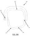
FIG. 18A , in some embodiments, aportion 478 of thesecond band 465 may be defined differently, such as to form a different shape (e.g., other than a U-shape). Along these lines, thesecond band 465 may define different shapes so as to provide for increased comfort within a user's mouth. For example, the shape of thesecond band 465 may define a bottom half of a hexagon. In such an embodiment, as thesecond band 465 is rotated relative to thefirst band 455, there may be more than one straight edge available to align with the bottom of the user's mouth. FIG. 19 shows another example embodiment of an adjustable bite block that incorporates a shelving-type, interference fit mechanism. In the depicted embodiment, theadjustable bite block 500 comprises afirst band 555 and asecond band 565 that connect to form a closed loop defining anopening 544. Thefirst band 555 is an elongated piece of curved material comprising afirst end 557 and asecond end 559. Thesecond band 565 also is an elongated piece of curved material comprising a first end 567 and a second end 569. In the depicted embodiment, the first andsecond bands adjustable bite block 500 may also comprise at least onewall 580 for keeping theadjustable bite block 500 in a person's mouth.- The
first band 555 may comprise at least twoslots 541 positioned near thefirst end 557 and thesecond end 559. Additionally, in order to enable connection of thefirst band 555 and thesecond band 565, thesecond band 565 may define one ormore protrusions 581 near the first end 567 and the second 569 that are configured to securely engage with one or more of the correspondingslots 541 of thefirst band 555. - In order to define the radial dimension of the loop and the
opening 544, thesecond band 565 may be slide out of engagement with the first band 555 (e.g., along arrow BB). Then, depending on the desired radial dimension of the loop andopening 544, eachprotrusion 581 may be aligned with and slid into acorresponding slot 541. For example, the twoprotrusions 581 on each end of thesecond band 565 may be aligned (and then engaged) with the top twoslots smaller opening 544 than that shown inFIG. 19 . - With reference to
FIG. 19A , in some embodiments, eachslot 541 of thefirst band 555 may define anend stop 579 that prevents theprotrusion 581 from being slid too far within theslot 541. Additionally or alternatively, in some embodiments, thecross-section 578 of eachslot 541 may decrease from the front 577 to theback 576. In such a manner, a user may feel resistance as theprotrusion 581 is slid along theslot 541, thereby further enhancing the interference fit of theprotrusion 581 andslot 541. FIG. 10 illustrates another example, wherein theoral apparatus 10 is configured to couple to aflexible strap 95 for holding theoral apparatus 10 in the person'smouth 16. Various embodiments of theoral apparatus 10, including previously described adjustable bite blocks 20, 40 may include at least oneconnector 90 protruding from theoral apparatus 10 and configured to couple to astrap 95. In the depicted embodiment, theoral apparatus 10 includes two radiallyopposite connectors 90 that are coupled to astrap 95 that is passed around the head of aperson 15. As shown inFIG. 11 , another embodiment of theoral apparatus 10 includes fourconnectors 90 spaced along theoral apparatus 10 to couple to a Y-shapedstrap 96. The Y-shapedstrap 96 is one flexible strap that forks into a "Y" before coupling to theconnectors 90 on theoral apparatus 10. The "Y" allows foradditional space 97 between the two forked straps coupled to theconnectors 90 on theoral apparatus 10. Theadditional space 97 can be used to pass additional medical instruments 11', such as suction tubes, into the person'smouth 16 without utilizing theopening 14 created by the closed loop of theoral apparatus 10.FIG. 12 shows another embodiment of an oral apparatus for maintaining a person's mouth open, wherein the oral apparatus is a wedge bite block. Thewedge bite block 100 comprises anupper surface 110 and alower surface 120. Theupper surface 110 andlower surface 120 may be configured along differently angled planes so as to form a general wedge shape. In the depicted embodiment, thelower surface 120 lies along a flat plane in comparison to the slightly downward sloping plane of theupper surface 110 of the wedge bite block 100 (as shown inFIG. 13 ).- The
wedge bite block 100 may also comprise at least onewedge wall 180. Thewedge wall 180 protrudes from the upper orlower surface wedge bite block 100 in place. In the depicted embodiment, theupper surface 110 comprises twowalls 180 located near the edges of theupper surface 110 so as to create a gap orupper slot 115 between thewalls 180 for fitting a person's upper gums or teeth. Additionally, thelower surface 120 also comprises twowalls 180 spaced near the edges to create alower slot 125 to engage and fit a person's lower gums or teeth. - The
wedge bite block 100 can be inserted into a person's mouth to prop open and maintain open their mouth. For example, thewedge bite block 100 can be placed between a person's upper and lower teeth. The slight downward angle of the plane of theupper surface 110 will correspond to the angle at which a person's mouth will be maintained open. Thus, in order to increase the angle at which a person's mouth is open either thewedge bite block 100 can be inserted further into a person's mouth or the slope of theupper surface 110 can be increased. In other embodiments, the plane of thelower surface 120 can be given a slope in order to increase or decrease the angle at which a person's mouth is held open. - As shown in
FIG. 14 , other embodiments of awedge bite block 100 may comprise ahandle 130. Thehandle 130 protrudes from thewedge bite block 100 toward the outside of a person's mouth and is configured to allow a user (e.g., doctor, nurse, patient, etc.) to easily place and position thewedge bite block 100 in a person's mouth. Thehandle 130 also ensures that the user, who is placing thewedge bite block 100 into a person's mouth, will not accidentally or otherwise be harmed if the person bites down while thewedge bite block 100 is being placed into the person's mouth. In some embodiments, thehandle 130 may comprise agrip 135 configured to allow a user to easily grab thehandle 130. FIG. 15 shows another embodiment of an oral apparatus for maintaining a person's mouth open, wherein the oral apparatus comprises two wedge bite blocks 100, 100'. The dualwedge bite block 200 comprises two wedge bite blocks 100, 100' configured to fit on either side of a person's mouth to maintain that person's mouth in the open position. In the depicted embodiment, the dualwedge bite block 200 also comprises aconnection band 140 connecting the individual wedge bite blocks 100, 100'. In various embodiments, one or both of the wedge bite blocks 100, 100' may also comprise ahandle 130 for easy placement and positioning of the dualwedge bite block 200. Also disclosed is a method for positioning an oral apparatus, such as any of the previously described apparatus embodiments, within a person's mouth. In another embodiment, the method comprises providing at least one band of curved material comprising a first portion and a second portion, coupling the first and second portions to one another so as to define a closed loop with an opening defined therethrough, and positioning the bite block within a person's mouth such that at least a portion of the loop engages the person's teeth to maintain the person's mouth in an open position. The method may further comprise adjusting the first and second portions relative to one another so as to adjust a radial dimension of the loop prior to the coupling step. The method may also further comprise inserting an instrument through the opening defined in the loop while the bite block is positioned within the person's mouth.- Many modifications and other embodiments of the inventions set forth herein will come to mind to one skilled in the art to which these inventions pertain having the benefit of the teachings presented in the foregoing descriptions and the associated drawings. Therefore, it is to be understood that the inventions are not to be limited to the specific embodiments disclosed and that modifications and other embodiments are intended to be included herein, when falling within the scope of the appended claims. Although specific terms are employed herein, they are used in a generic and descriptive sense only and not for purposes of limitation.
Claims (6)
- An adjustable bite block (500) for positioning within a person's mouth and maintaining the mouth in an open position, the adjustable bite block comprising: at least one band (555, 565) of curved material comprising a first portion and a second portion, the first and second portions configured to be coupled to one another so as to define a closed loop with an opening defined therethrough, wherein the first and second portions are further configured to be selectively adjusted relative to one another so as to adjust a radial dimension of the loop, and wherein the band is configured to be positioned within the person's mouth such that at least a portion of the loop maintains the person's mouth in an open position,characterized in that the first portion defines at least two slots (541) at different heights,in that the second portion defines at least one protrusion (581) andin that each slot is configured to receive the at least one protrusion to define a radial dimension of the opening.
- The adjustable bite block of claim 1, wherein the at least one protrusion of the second portion is configured to be slidably removed from the at least one slot of the first portion and repositioned into a different at least one slot of the first portion to define a different radial dimension of the opening.
- The adjustable bite block of claim 1 further comprising at least one wall (580) configured for keeping the adjustable bite block in a person's mouth.
- The adjustable bite block of claim 3, wherein the at least one wall extends radially from the first portion of the at least one band.
- The adjustable bite block of claim 1, wherein each slot comprises an end stop (579) configured to prevent a respective protrusion from being slid past a predetermined point within the respective slot.
- The adjustable bite block of claim 1, wherein each slot defines a cross-sectional dimension (578) that decreases from a front part of a respective slot to a back part of the respective slot such that a resistance to engagement of a respective protrusion within the respective slot increases as the respective protrusion is slid further into the respective lot.
Priority Applications (1)
| Application Number | Priority Date | Filing Date | Title |
|---|---|---|---|
| EP18162157.4AEP3354189A1 (en) | 2013-03-13 | 2014-03-13 | Adjustable bite blocks |
Applications Claiming Priority (2)
| Application Number | Priority Date | Filing Date | Title |
|---|---|---|---|
| US201361780137P | 2013-03-13 | 2013-03-13 | |
| PCT/US2014/025548WO2014159973A1 (en) | 2013-03-13 | 2014-03-13 | Adjustable bite blocks |
Related Child Applications (2)
| Application Number | Title | Priority Date | Filing Date |
|---|---|---|---|
| EP18162157.4ADivisionEP3354189A1 (en) | 2013-03-13 | 2014-03-13 | Adjustable bite blocks |
| EP18162157.4ADivision-IntoEP3354189A1 (en) | 2013-03-13 | 2014-03-13 | Adjustable bite blocks |
Publications (2)
| Publication Number | Publication Date |
|---|---|
| EP2967303A1 EP2967303A1 (en) | 2016-01-20 |
| EP2967303B1true EP2967303B1 (en) | 2018-05-09 |
Family
ID=50686131
Family Applications (2)
| Application Number | Title | Priority Date | Filing Date |
|---|---|---|---|
| EP18162157.4AWithdrawnEP3354189A1 (en) | 2013-03-13 | 2014-03-13 | Adjustable bite blocks |
| EP14722843.1ANot-in-forceEP2967303B1 (en) | 2013-03-13 | 2014-03-13 | Adjustable bite blocks |
Family Applications Before (1)
| Application Number | Title | Priority Date | Filing Date |
|---|---|---|---|
| EP18162157.4AWithdrawnEP3354189A1 (en) | 2013-03-13 | 2014-03-13 | Adjustable bite blocks |
Country Status (8)
| Country | Link |
|---|---|
| US (2) | US9237841B2 (en) |
| EP (2) | EP3354189A1 (en) |
| CN (1) | CN105307557B (en) |
| AU (1) | AU2014244237B2 (en) |
| BR (1) | BR112015022334A2 (en) |
| CA (1) | CA2905928C (en) |
| MX (1) | MX2015011971A (en) |
| WO (1) | WO2014159973A1 (en) |
Cited By (1)
| Publication number | Priority date | Publication date | Assignee | Title |
|---|---|---|---|---|
| CN111616812A (en)* | 2020-06-08 | 2020-09-04 | 王咏梅 | Gastroenterology gastroscope pipe fixed knot constructs |
Families Citing this family (29)
| Publication number | Priority date | Publication date | Assignee | Title |
|---|---|---|---|---|
| EP2242714B1 (en)* | 2008-02-22 | 2014-08-13 | Lamiflex AB | Protective insert |
| WO2014159973A1 (en) | 2013-03-13 | 2014-10-02 | Bracco Diagnostics Inc. | Adjustable bite blocks |
| US10561310B2 (en) | 2014-06-03 | 2020-02-18 | It's Lit Lighting Solutions Llc | Lighted bite block |
| CN104622418A (en)* | 2015-02-02 | 2015-05-20 | 成都科力夫科技有限公司 | Mouth gag for emergent treatment |
| US9968341B2 (en) | 2015-04-21 | 2018-05-15 | Ascentcare Dental Labs, Llc | Dental bite block assembly |
| WO2016191345A1 (en) | 2015-05-22 | 2016-12-01 | The Research Institute At Nationwide Children's Hospital | Protective mouth assembly and method of operation |
| CN105286764B (en)* | 2015-10-21 | 2017-01-18 | 王世江 | Tongue depressing detection system |
| USD788300S1 (en)* | 2015-10-27 | 2017-05-30 | Orthogrid Systems, Inc. | Grid positioning device |
| USD782047S1 (en) | 2016-04-20 | 2017-03-21 | Ascentcare Dental Labs, Llc | Dental accessory for holding a saliva ejection tube |
| USD787070S1 (en) | 2016-04-20 | 2017-05-16 | Ascentcare Dental Labs | Illuminated dental accessory with tongue suppressor |
| USD782048S1 (en)* | 2016-04-20 | 2017-03-21 | Ascentcare Dental Labs, Llc | Dental bite block |
| USD787069S1 (en) | 2016-04-20 | 2017-05-16 | Ascentcare Dental Labs | Illuminated dental accessory for holding saliva ejection tube |
| USD817492S1 (en) | 2016-04-20 | 2018-05-08 | Ascentcare Dental Labs, Llc | Dental accessory with tongue suppressor |
| CN106880334A (en)* | 2017-04-01 | 2017-06-23 | 王新本 | A kind of Respiratory Medicine inspection oral cavity support device |
| CA3063744A1 (en)* | 2017-06-30 | 2019-01-03 | Innovgas Pty Ltd | Tapered compressible bite block |
| CN109125817A (en)* | 2018-06-07 | 2019-01-04 | 刘静 | Infant's sputum aspirator |
| CN108969859B (en)* | 2018-06-21 | 2020-09-08 | 青岛市口腔医院 | Adjustable trachea cannula fixing device |
| US20210170128A1 (en)* | 2018-07-03 | 2021-06-10 | Alan Ringel | Guard apparatus and method for laryngeal mask airway |
| CN111887790A (en)* | 2018-08-24 | 2020-11-06 | 孙载位 | Body opener for wrapping and making up and using method |
| CN110522978A (en)* | 2019-05-29 | 2019-12-03 | 邵珠雨 | A kind of department of anesthesia's multichannel pars oralis pharyngis air-breather |
| CN114423370B (en)* | 2019-07-24 | 2024-10-11 | 尼奥西斯股份有限公司 | Splinting device forming fiducial markers cooperable with a guiding system of a robot |
| CN111166280B (en)* | 2020-01-08 | 2021-07-09 | 哈尔滨理工大学 | An adjustable support device |
| US20210390400A1 (en)* | 2020-06-16 | 2021-12-16 | Sri International | Progressive neural ordinary differential equations |
| WO2022098770A1 (en)* | 2020-11-03 | 2022-05-12 | Md Medical Design, Inc. | Cheek retraction device |
| US20220134036A1 (en)* | 2020-11-05 | 2022-05-05 | Innovation Ventures Ip At Ukhs, Llc | Bite block |
| CN112244745B (en)* | 2020-11-16 | 2022-09-23 | 乳山市人民医院 | Stable anti-damage oral repair supporting device and adjusting method thereof |
| CN114073845B (en)* | 2021-11-29 | 2022-09-16 | 南通市肿瘤医院 | Intelligent rehabilitation device for radiotherapy department |
| IT202200020697A1 (en)* | 2022-10-07 | 2024-04-07 | Medsniper S R L | Oral retractor for orotracheal intubation procedures |
| CN119073884B (en)* | 2024-10-29 | 2025-04-08 | 中国人民解放军总医院第二医学中心 | Auxiliary device of digestive endoscope and application method thereof |
Family Cites Families (43)
| Publication number | Priority date | Publication date | Assignee | Title |
|---|---|---|---|---|
| GB183301A (en)* | 1921-05-21 | 1922-07-27 | Dental Mfg Co Ltd | Improvements in mouth props |
| US2823455A (en) | 1956-04-24 | 1958-02-18 | Boyd F Sprague | Dental instrument |
| US4167814A (en) | 1977-04-11 | 1979-09-18 | Schubert Robert E | Mouth prop and oral evacuation device |
| US4304227A (en) | 1978-03-03 | 1981-12-08 | Samelson Charles F | Device for treatment of snoring, bruxism or for avoidance of sleep apnea |
| USD283158S (en) | 1983-04-08 | 1986-03-25 | Frank W. Jackson | Endoscopic bite block |
| US4640273A (en) | 1985-05-08 | 1987-02-03 | E-Z-Em, Inc. | Mouth guard for use with a diagnostic instrument |
| SE464909B (en) | 1988-02-19 | 1991-07-01 | Tandlaekare Dyfvermark Ab | DENTAL BITKLOSS CONNECT TO SUGKAELLA |
| US4887965A (en) | 1988-08-02 | 1989-12-19 | Fox Henry L | Adjustable mouth prop |
| US5069206A (en)* | 1990-06-11 | 1991-12-03 | Crosbie David B | Endotracheal tube clutch |
| US5174284A (en) | 1991-09-05 | 1992-12-29 | G.I. Supply, Inc. | Endoscopic bite block |
| US5466153A (en) | 1992-01-22 | 1995-11-14 | Poindexter; Forrest R. | Prop for use in dentistry and oral surgery |
| FR2711320B1 (en) | 1993-10-11 | 1996-01-05 | Ist Medical | Wedging and spacing cannula. |
| US5570704A (en) | 1993-10-28 | 1996-11-05 | Snoreless Corp | Universal, user-adjustable oral cavity appliance to control snoring and reduce episodes of obstructive sleep apnea |
| US5588836A (en) | 1995-10-23 | 1996-12-31 | Op-D-Op, Inc. | Mouth prop and tongue deflector apparatus |
| US5655519A (en) | 1995-11-14 | 1997-08-12 | Alfery; David D. | Patient airway bite block |
| US5879155A (en) | 1996-08-05 | 1999-03-09 | Big Picture, Inc. | Adjustable customized composite dental appliance with wire band |
| US5730599A (en) | 1996-11-12 | 1998-03-24 | Pak; Elizabeth Y. | Protective dental shield |
| US5733121A (en) | 1997-05-01 | 1998-03-31 | Goode; Macdonald H. | Mandible lock device |
| US5890899A (en) | 1997-06-27 | 1999-04-06 | Intellitech Corporation | Dental isolator |
| US6241521B1 (en) | 1998-07-13 | 2001-06-05 | John E. Garrison | Bite block |
| US6244866B1 (en) | 1999-12-29 | 2001-06-12 | Regina Campbell | Tongue suppressing bite block |
| JP2002003335A (en) | 2000-04-21 | 2002-01-09 | Koden Kk | Coating composition for cosmetic, removing agent therefor, and opened lips intraoral supporter |
| US7568484B2 (en) | 2001-10-11 | 2009-08-04 | Venetec International, Inc. | Endo-tracheal tube securement system |
| US6652276B2 (en) | 2001-11-01 | 2003-11-25 | Ultradent Products, Inc. | Customizable dental bite blocks and methods for forming customized dental bite blocks |
| US6655960B2 (en) | 2001-11-01 | 2003-12-02 | Ultradent Products, Inc. | Tongue suppressing bite block adaptable to varying mouth and tongue sizes |
| USD564658S1 (en) | 2002-11-22 | 2008-03-18 | Ross William Anderson | Apparatus for maintaining a dry field during dental procedures |
| US7785105B2 (en) | 2002-11-22 | 2010-08-31 | Ross William Anderson | Apparatus for maintaining a dry field during dental procedures |
| US6983752B2 (en) | 2004-03-11 | 2006-01-10 | Sleep Sound Services Zzz | Dental appliance for the treatment of sleep disorders |
| US20050239017A1 (en) | 2004-04-23 | 2005-10-27 | Lim Ki B | Ring-shaped illuminated mouth prop |
| US20050239018A1 (en) | 2004-04-27 | 2005-10-27 | Scott Green | Intraoral bite spacer and illumination apparatus |
| US20060110705A1 (en) | 2004-11-19 | 2006-05-25 | Jensen Steven D | Accessible dental bite block |
| US7442040B2 (en) | 2005-01-13 | 2008-10-28 | Align Technology, Inc. | Template for veneer application |
| US20070218422A1 (en) | 2006-02-24 | 2007-09-20 | Ehrenfeld Richard J | Adjustable cheek retractor with saliva extracting tongue guard |
| US20080153057A1 (en) | 2006-12-22 | 2008-06-26 | Baldwin Charles C | Awake airway: non-stimulating (non-gagging) feature |
| US7866313B2 (en)* | 2007-01-02 | 2011-01-11 | Isen Innovations, Llc | Oral airways that facilitate tracheal intubation |
| JP5518700B2 (en) | 2007-06-04 | 2014-06-11 | エシコン・エンド−サージェリィ・インコーポレイテッド | Endoscopic bite blocker for use with a cannula |
| US7963286B2 (en) | 2007-08-10 | 2011-06-21 | Infohealthnetwork, Inc. | Combination bite block, tongue depressor/retractor and airway |
| CA2728037A1 (en) | 2008-06-19 | 2009-12-23 | Bite Tech, Inc. | Oral appliances with major connectors and methods for manufacture |
| US8631800B2 (en)* | 2009-06-29 | 2014-01-21 | Sleep Science Partners, Inc. | Self-titratable mandibular repositioning device |
| CN102711884B (en)* | 2009-12-04 | 2014-07-16 | 皇家飞利浦电子股份有限公司 | Apparatus and method comprising adjustable stepped mouthpiece for aerosol drug delivery |
| CN202060753U (en)* | 2011-05-11 | 2011-12-07 | 宁波冠克贸易有限公司 | Seaming device of endoscope |
| CN202262973U (en)* | 2011-10-24 | 2012-06-06 | 邢洪波 | Medical mouth opener |
| WO2014159973A1 (en) | 2013-03-13 | 2014-10-02 | Bracco Diagnostics Inc. | Adjustable bite blocks |
- 2014
- 2014-03-13WOPCT/US2014/025548patent/WO2014159973A1/enactiveApplication Filing
- 2014-03-13EPEP18162157.4Apatent/EP3354189A1/ennot_activeWithdrawn
- 2014-03-13AUAU2014244237Apatent/AU2014244237B2/ennot_activeCeased
- 2014-03-13USUS14/208,400patent/US9237841B2/enactiveActive
- 2014-03-13EPEP14722843.1Apatent/EP2967303B1/ennot_activeNot-in-force
- 2014-03-13CNCN201480027132.1Apatent/CN105307557B/ennot_activeExpired - Fee Related
- 2014-03-13BRBR112015022334Apatent/BR112015022334A2/ennot_activeApplication Discontinuation
- 2014-03-13MXMX2015011971Apatent/MX2015011971A/enunknown
- 2014-03-13CACA2905928Apatent/CA2905928C/ennot_activeExpired - Fee Related
- 2016
- 2016-01-13USUS14/994,651patent/US9585551B2/enactiveActive
Non-Patent Citations (1)
| Title |
|---|
| None* |
Cited By (1)
| Publication number | Priority date | Publication date | Assignee | Title |
|---|---|---|---|---|
| CN111616812A (en)* | 2020-06-08 | 2020-09-04 | 王咏梅 | Gastroenterology gastroscope pipe fixed knot constructs |
Also Published As
| Publication number | Publication date |
|---|---|
| AU2014244237A1 (en) | 2015-10-22 |
| AU2014244237B2 (en) | 2016-09-22 |
| BR112015022334A2 (en) | 2017-07-18 |
| CN105307557A (en) | 2016-02-03 |
| CN105307557B (en) | 2017-09-05 |
| US9585551B2 (en) | 2017-03-07 |
| CA2905928A1 (en) | 2014-10-02 |
| MX2015011971A (en) | 2016-06-07 |
| EP3354189A1 (en) | 2018-08-01 |
| US9237841B2 (en) | 2016-01-19 |
| US20160120399A1 (en) | 2016-05-05 |
| US20140275803A1 (en) | 2014-09-18 |
| CA2905928C (en) | 2017-10-03 |
| WO2014159973A1 (en) | 2014-10-02 |
| EP2967303A1 (en) | 2016-01-20 |
Similar Documents
| Publication | Publication Date | Title |
|---|---|---|
| EP2967303B1 (en) | Adjustable bite blocks | |
| JP7618172B2 (en) | Dental Equipment | |
| KR101695355B1 (en) | Dental Wire Supporter For Orthodontic Treatment And Orthodontic Device Having The Same | |
| JP6068350B2 (en) | Intrauterine insertion device | |
| US20070218422A1 (en) | Adjustable cheek retractor with saliva extracting tongue guard | |
| EP4282376A3 (en) | Indirect bonding tray having several handles | |
| US9498025B2 (en) | Strap attachment system for orthopedic device | |
| BRPI0813295B1 (en) | Orthodontic bracket | |
| US10888680B2 (en) | Endotracheal tube holder device | |
| US9872742B1 (en) | Orthodontic hand instrument | |
| US20110229847A1 (en) | Dental appliance with prop member and saliva ejector | |
| US20130269712A1 (en) | Adjustable bite plane appliance | |
| US5993207A (en) | Orthodontic accessory for corrective force application to orthodontic bracket | |
| EP3158968A1 (en) | Bracket, bracket straightening system and teeth straightening method | |
| US20130068233A1 (en) | Endotracheal tube stabilizer apparatus and method | |
| US7713057B2 (en) | Oral mucous membrane protector for orthodontic applications | |
| US9827071B2 (en) | Intraoral protection | |
| CN103260554B (en) | Medical Restraint Devices for Hollow Organs of the Body | |
| WO2014164277A1 (en) | Devices and methods for securing an anti-leak feeding tube for gastric and/or intestinal use | |
| US20160038259A1 (en) | Dental appliance for adjusting the position of the lower jaw of a patient with respect to the upper jaw thereof | |
| WO2016205834A1 (en) | Multi-size gastric bypass band and surgical method | |
| CN103961184B (en) | Self-ligating bracket of movable wing | |
| EP3476291B1 (en) | Oropharyngeal measurement device and method | |
| KR20170031739A (en) | An orthodontic ligature | |
| US11311356B1 (en) | Finger rest clip for dental impression tray |
Legal Events
| Date | Code | Title | Description |
|---|---|---|---|
| PUAI | Public reference made under article 153(3) epc to a published international application that has entered the european phase | Free format text:ORIGINAL CODE: 0009012 | |
| 17P | Request for examination filed | Effective date:20150930 | |
| AK | Designated contracting states | Kind code of ref document:A1 Designated state(s):AL AT BE BG CH CY CZ DE DK EE ES FI FR GB GR HR HU IE IS IT LI LT LU LV MC MK MT NL NO PL PT RO RS SE SI SK SM TR | |
| AX | Request for extension of the european patent | Extension state:BA ME | |
| RIN1 | Information on inventor provided before grant (corrected) | Inventor name:CUSHNER, JEFFREY, B. Inventor name:DUMAN, ALI, HAKAN Inventor name:STEBBINS, CHRISTOPHER, R. Inventor name:WOLCOTT, KENNETH, E. | |
| DAX | Request for extension of the european patent (deleted) | ||
| RAP1 | Party data changed (applicant data changed or rights of an application transferred) | Owner name:UNITED STATES ENDOSCOPY GROUP, INC. | |
| GRAP | Despatch of communication of intention to grant a patent | Free format text:ORIGINAL CODE: EPIDOSNIGR1 | |
| STAA | Information on the status of an ep patent application or granted ep patent | Free format text:STATUS: GRANT OF PATENT IS INTENDED | |
| INTG | Intention to grant announced | Effective date:20171116 | |
| RIN1 | Information on inventor provided before grant (corrected) | Inventor name:DUMAN, ALI HAKAN Inventor name:CUSHNER, JEFFREY B. Inventor name:WOLCOTT, KENNETH E. Inventor name:STEBBINS, CHRISTOPHER R. | |
| GRAJ | Information related to disapproval of communication of intention to grant by the applicant or resumption of examination proceedings by the epo deleted | Free format text:ORIGINAL CODE: EPIDOSDIGR1 | |
| GRAS | Grant fee paid | Free format text:ORIGINAL CODE: EPIDOSNIGR3 | |
| GRAA | (expected) grant | Free format text:ORIGINAL CODE: 0009210 | |
| STAA | Information on the status of an ep patent application or granted ep patent | Free format text:STATUS: THE PATENT HAS BEEN GRANTED | |
| INTG | Intention to grant announced | Effective date:20171116 | |
| AK | Designated contracting states | Kind code of ref document:B1 Designated state(s):AL AT BE BG CH CY CZ DE DK EE ES FI FR GB GR HR HU IE IS IT LI LT LU LV MC MK MT NL NO PL PT RO RS SE SI SK SM TR | |
| REG | Reference to a national code | Ref country code:GB Ref legal event code:FG4D | |
| REG | Reference to a national code | Ref country code:CH Ref legal event code:EP Ref country code:AT Ref legal event code:REF Ref document number:996758 Country of ref document:AT Kind code of ref document:T Effective date:20180515 | |
| REG | Reference to a national code | Ref country code:IE Ref legal event code:FG4D | |
| REG | Reference to a national code | Ref country code:DE Ref legal event code:R096 Ref document number:602014025214 Country of ref document:DE | |
| REG | Reference to a national code | Ref country code:NL Ref legal event code:MP Effective date:20180509 | |
| REG | Reference to a national code | Ref country code:LT Ref legal event code:MG4D | |
| PG25 | Lapsed in a contracting state [announced via postgrant information from national office to epo] | Ref country code:BG Free format text:LAPSE BECAUSE OF FAILURE TO SUBMIT A TRANSLATION OF THE DESCRIPTION OR TO PAY THE FEE WITHIN THE PRESCRIBED TIME-LIMIT Effective date:20180809 Ref country code:FI Free format text:LAPSE BECAUSE OF FAILURE TO SUBMIT A TRANSLATION OF THE DESCRIPTION OR TO PAY THE FEE WITHIN THE PRESCRIBED TIME-LIMIT Effective date:20180509 Ref country code:NO Free format text:LAPSE BECAUSE OF FAILURE TO SUBMIT A TRANSLATION OF THE DESCRIPTION OR TO PAY THE FEE WITHIN THE PRESCRIBED TIME-LIMIT Effective date:20180809 Ref country code:SE Free format text:LAPSE BECAUSE OF FAILURE TO SUBMIT A TRANSLATION OF THE DESCRIPTION OR TO PAY THE FEE WITHIN THE PRESCRIBED TIME-LIMIT Effective date:20180509 Ref country code:LT Free format text:LAPSE BECAUSE OF FAILURE TO SUBMIT A TRANSLATION OF THE DESCRIPTION OR TO PAY THE FEE WITHIN THE PRESCRIBED TIME-LIMIT Effective date:20180509 Ref country code:ES Free format text:LAPSE BECAUSE OF FAILURE TO SUBMIT A TRANSLATION OF THE DESCRIPTION OR TO PAY THE FEE WITHIN THE PRESCRIBED TIME-LIMIT Effective date:20180509 | |
| PG25 | Lapsed in a contracting state [announced via postgrant information from national office to epo] | Ref country code:LV Free format text:LAPSE BECAUSE OF FAILURE TO SUBMIT A TRANSLATION OF THE DESCRIPTION OR TO PAY THE FEE WITHIN THE PRESCRIBED TIME-LIMIT Effective date:20180509 Ref country code:NL Free format text:LAPSE BECAUSE OF FAILURE TO SUBMIT A TRANSLATION OF THE DESCRIPTION OR TO PAY THE FEE WITHIN THE PRESCRIBED TIME-LIMIT Effective date:20180509 Ref country code:HR Free format text:LAPSE BECAUSE OF FAILURE TO SUBMIT A TRANSLATION OF THE DESCRIPTION OR TO PAY THE FEE WITHIN THE PRESCRIBED TIME-LIMIT Effective date:20180509 Ref country code:GR Free format text:LAPSE BECAUSE OF FAILURE TO SUBMIT A TRANSLATION OF THE DESCRIPTION OR TO PAY THE FEE WITHIN THE PRESCRIBED TIME-LIMIT Effective date:20180810 Ref country code:RS Free format text:LAPSE BECAUSE OF FAILURE TO SUBMIT A TRANSLATION OF THE DESCRIPTION OR TO PAY THE FEE WITHIN THE PRESCRIBED TIME-LIMIT Effective date:20180509 | |
| REG | Reference to a national code | Ref country code:AT Ref legal event code:MK05 Ref document number:996758 Country of ref document:AT Kind code of ref document:T Effective date:20180509 | |
| PG25 | Lapsed in a contracting state [announced via postgrant information from national office to epo] | Ref country code:EE Free format text:LAPSE BECAUSE OF FAILURE TO SUBMIT A TRANSLATION OF THE DESCRIPTION OR TO PAY THE FEE WITHIN THE PRESCRIBED TIME-LIMIT Effective date:20180509 Ref country code:PL Free format text:LAPSE BECAUSE OF FAILURE TO SUBMIT A TRANSLATION OF THE DESCRIPTION OR TO PAY THE FEE WITHIN THE PRESCRIBED TIME-LIMIT Effective date:20180509 Ref country code:DK Free format text:LAPSE BECAUSE OF FAILURE TO SUBMIT A TRANSLATION OF THE DESCRIPTION OR TO PAY THE FEE WITHIN THE PRESCRIBED TIME-LIMIT Effective date:20180509 Ref country code:AT Free format text:LAPSE BECAUSE OF FAILURE TO SUBMIT A TRANSLATION OF THE DESCRIPTION OR TO PAY THE FEE WITHIN THE PRESCRIBED TIME-LIMIT Effective date:20180509 Ref country code:CZ Free format text:LAPSE BECAUSE OF FAILURE TO SUBMIT A TRANSLATION OF THE DESCRIPTION OR TO PAY THE FEE WITHIN THE PRESCRIBED TIME-LIMIT Effective date:20180509 Ref country code:RO Free format text:LAPSE BECAUSE OF FAILURE TO SUBMIT A TRANSLATION OF THE DESCRIPTION OR TO PAY THE FEE WITHIN THE PRESCRIBED TIME-LIMIT Effective date:20180509 Ref country code:SK Free format text:LAPSE BECAUSE OF FAILURE TO SUBMIT A TRANSLATION OF THE DESCRIPTION OR TO PAY THE FEE WITHIN THE PRESCRIBED TIME-LIMIT Effective date:20180509 | |
| REG | Reference to a national code | Ref country code:DE Ref legal event code:R097 Ref document number:602014025214 Country of ref document:DE | |
| PG25 | Lapsed in a contracting state [announced via postgrant information from national office to epo] | Ref country code:IT Free format text:LAPSE BECAUSE OF FAILURE TO SUBMIT A TRANSLATION OF THE DESCRIPTION OR TO PAY THE FEE WITHIN THE PRESCRIBED TIME-LIMIT Effective date:20180509 Ref country code:SM Free format text:LAPSE BECAUSE OF FAILURE TO SUBMIT A TRANSLATION OF THE DESCRIPTION OR TO PAY THE FEE WITHIN THE PRESCRIBED TIME-LIMIT Effective date:20180509 | |
| PLBE | No opposition filed within time limit | Free format text:ORIGINAL CODE: 0009261 | |
| STAA | Information on the status of an ep patent application or granted ep patent | Free format text:STATUS: NO OPPOSITION FILED WITHIN TIME LIMIT | |
| 26N | No opposition filed | Effective date:20190212 | |
| PG25 | Lapsed in a contracting state [announced via postgrant information from national office to epo] | Ref country code:SI Free format text:LAPSE BECAUSE OF FAILURE TO SUBMIT A TRANSLATION OF THE DESCRIPTION OR TO PAY THE FEE WITHIN THE PRESCRIBED TIME-LIMIT Effective date:20180509 | |
| REG | Reference to a national code | Ref country code:DE Ref legal event code:R119 Ref document number:602014025214 Country of ref document:DE | |
| PG25 | Lapsed in a contracting state [announced via postgrant information from national office to epo] | Ref country code:MC Free format text:LAPSE BECAUSE OF FAILURE TO SUBMIT A TRANSLATION OF THE DESCRIPTION OR TO PAY THE FEE WITHIN THE PRESCRIBED TIME-LIMIT Effective date:20180509 | |
| REG | Reference to a national code | Ref country code:CH Ref legal event code:PL | |
| GBPC | Gb: european patent ceased through non-payment of renewal fee | Effective date:20190313 | |
| PG25 | Lapsed in a contracting state [announced via postgrant information from national office to epo] | Ref country code:LU Free format text:LAPSE BECAUSE OF NON-PAYMENT OF DUE FEES Effective date:20190313 Ref country code:AL Free format text:LAPSE BECAUSE OF FAILURE TO SUBMIT A TRANSLATION OF THE DESCRIPTION OR TO PAY THE FEE WITHIN THE PRESCRIBED TIME-LIMIT Effective date:20180509 | |
| REG | Reference to a national code | Ref country code:BE Ref legal event code:MM Effective date:20190331 | |
| PG25 | Lapsed in a contracting state [announced via postgrant information from national office to epo] | Ref country code:DE Free format text:LAPSE BECAUSE OF NON-PAYMENT OF DUE FEES Effective date:20191001 Ref country code:LI Free format text:LAPSE BECAUSE OF NON-PAYMENT OF DUE FEES Effective date:20190331 Ref country code:IE Free format text:LAPSE BECAUSE OF NON-PAYMENT OF DUE FEES Effective date:20190313 Ref country code:GB Free format text:LAPSE BECAUSE OF NON-PAYMENT OF DUE FEES Effective date:20190313 Ref country code:CH Free format text:LAPSE BECAUSE OF NON-PAYMENT OF DUE FEES Effective date:20190331 | |
| PG25 | Lapsed in a contracting state [announced via postgrant information from national office to epo] | Ref country code:BE Free format text:LAPSE BECAUSE OF NON-PAYMENT OF DUE FEES Effective date:20190331 Ref country code:FR Free format text:LAPSE BECAUSE OF NON-PAYMENT OF DUE FEES Effective date:20190331 | |
| PG25 | Lapsed in a contracting state [announced via postgrant information from national office to epo] | Ref country code:TR Free format text:LAPSE BECAUSE OF FAILURE TO SUBMIT A TRANSLATION OF THE DESCRIPTION OR TO PAY THE FEE WITHIN THE PRESCRIBED TIME-LIMIT Effective date:20180509 | |
| PG25 | Lapsed in a contracting state [announced via postgrant information from national office to epo] | Ref country code:PT Free format text:LAPSE BECAUSE OF FAILURE TO SUBMIT A TRANSLATION OF THE DESCRIPTION OR TO PAY THE FEE WITHIN THE PRESCRIBED TIME-LIMIT Effective date:20180910 Ref country code:MT Free format text:LAPSE BECAUSE OF NON-PAYMENT OF DUE FEES Effective date:20190313 | |
| PG25 | Lapsed in a contracting state [announced via postgrant information from national office to epo] | Ref country code:CY Free format text:LAPSE BECAUSE OF FAILURE TO SUBMIT A TRANSLATION OF THE DESCRIPTION OR TO PAY THE FEE WITHIN THE PRESCRIBED TIME-LIMIT Effective date:20180509 | |
| PG25 | Lapsed in a contracting state [announced via postgrant information from national office to epo] | Ref country code:IS Free format text:LAPSE BECAUSE OF FAILURE TO SUBMIT A TRANSLATION OF THE DESCRIPTION OR TO PAY THE FEE WITHIN THE PRESCRIBED TIME-LIMIT Effective date:20180909 | |
| PG25 | Lapsed in a contracting state [announced via postgrant information from national office to epo] | Ref country code:HU Free format text:LAPSE BECAUSE OF FAILURE TO SUBMIT A TRANSLATION OF THE DESCRIPTION OR TO PAY THE FEE WITHIN THE PRESCRIBED TIME-LIMIT; INVALID AB INITIO Effective date:20140313 | |
| PG25 | Lapsed in a contracting state [announced via postgrant information from national office to epo] | Ref country code:MK Free format text:LAPSE BECAUSE OF FAILURE TO SUBMIT A TRANSLATION OF THE DESCRIPTION OR TO PAY THE FEE WITHIN THE PRESCRIBED TIME-LIMIT Effective date:20180509 |