EP2964924B1 - Gas turbine engine inlet - Google Patents
Gas turbine engine inletDownload PDFInfo
- Publication number
- EP2964924B1 EP2964924B1EP14759888.2AEP14759888AEP2964924B1EP 2964924 B1EP2964924 B1EP 2964924B1EP 14759888 AEP14759888 AEP 14759888AEP 2964924 B1EP2964924 B1EP 2964924B1
- Authority
- EP
- European Patent Office
- Prior art keywords
- fan
- inlet
- gas turbine
- turbine engine
- spinner
- Prior art date
- Legal status (The legal status is an assumption and is not a legal conclusion. Google has not performed a legal analysis and makes no representation as to the accuracy of the status listed.)
- Active
Links
Images


Classifications
- F—MECHANICAL ENGINEERING; LIGHTING; HEATING; WEAPONS; BLASTING
- F02—COMBUSTION ENGINES; HOT-GAS OR COMBUSTION-PRODUCT ENGINE PLANTS
- F02C—GAS-TURBINE PLANTS; AIR INTAKES FOR JET-PROPULSION PLANTS; CONTROLLING FUEL SUPPLY IN AIR-BREATHING JET-PROPULSION PLANTS
- F02C7/00—Features, components parts, details or accessories, not provided for in, or of interest apart form groups F02C1/00 - F02C6/00; Air intakes for jet-propulsion plants
- F02C7/04—Air intakes for gas-turbine plants or jet-propulsion plants
- F—MECHANICAL ENGINEERING; LIGHTING; HEATING; WEAPONS; BLASTING
- F01—MACHINES OR ENGINES IN GENERAL; ENGINE PLANTS IN GENERAL; STEAM ENGINES
- F01D—NON-POSITIVE DISPLACEMENT MACHINES OR ENGINES, e.g. STEAM TURBINES
- F01D17/00—Regulating or controlling by varying flow
- F01D17/10—Final actuators
- F01D17/105—Final actuators by passing part of the fluid
- F—MECHANICAL ENGINEERING; LIGHTING; HEATING; WEAPONS; BLASTING
- F01—MACHINES OR ENGINES IN GENERAL; ENGINE PLANTS IN GENERAL; STEAM ENGINES
- F01D—NON-POSITIVE DISPLACEMENT MACHINES OR ENGINES, e.g. STEAM TURBINES
- F01D25/00—Component parts, details, or accessories, not provided for in, or of interest apart from, other groups
- F01D25/24—Casings; Casing parts, e.g. diaphragms, casing fastenings
- F—MECHANICAL ENGINEERING; LIGHTING; HEATING; WEAPONS; BLASTING
- F01—MACHINES OR ENGINES IN GENERAL; ENGINE PLANTS IN GENERAL; STEAM ENGINES
- F01D—NON-POSITIVE DISPLACEMENT MACHINES OR ENGINES, e.g. STEAM TURBINES
- F01D5/00—Blades; Blade-carrying members; Heating, heat-insulating, cooling or antivibration means on the blades or the members
- F01D5/02—Blade-carrying members, e.g. rotors
- F—MECHANICAL ENGINEERING; LIGHTING; HEATING; WEAPONS; BLASTING
- F02—COMBUSTION ENGINES; HOT-GAS OR COMBUSTION-PRODUCT ENGINE PLANTS
- F02C—GAS-TURBINE PLANTS; AIR INTAKES FOR JET-PROPULSION PLANTS; CONTROLLING FUEL SUPPLY IN AIR-BREATHING JET-PROPULSION PLANTS
- F02C3/00—Gas-turbine plants characterised by the use of combustion products as the working fluid
- F02C3/04—Gas-turbine plants characterised by the use of combustion products as the working fluid having a turbine driving a compressor
- F—MECHANICAL ENGINEERING; LIGHTING; HEATING; WEAPONS; BLASTING
- F02—COMBUSTION ENGINES; HOT-GAS OR COMBUSTION-PRODUCT ENGINE PLANTS
- F02K—JET-PROPULSION PLANTS
- F02K3/00—Plants including a gas turbine driving a compressor or a ducted fan
- F02K3/02—Plants including a gas turbine driving a compressor or a ducted fan in which part of the working fluid by-passes the turbine and combustion chamber
- F02K3/04—Plants including a gas turbine driving a compressor or a ducted fan in which part of the working fluid by-passes the turbine and combustion chamber the plant including ducted fans, i.e. fans with high volume, low pressure outputs, for augmenting the jet thrust, e.g. of double-flow type
- F02K3/06—Plants including a gas turbine driving a compressor or a ducted fan in which part of the working fluid by-passes the turbine and combustion chamber the plant including ducted fans, i.e. fans with high volume, low pressure outputs, for augmenting the jet thrust, e.g. of double-flow type with front fan
- B—PERFORMING OPERATIONS; TRANSPORTING
- B64—AIRCRAFT; AVIATION; COSMONAUTICS
- B64D—EQUIPMENT FOR FITTING IN OR TO AIRCRAFT; FLIGHT SUITS; PARACHUTES; ARRANGEMENT OR MOUNTING OF POWER PLANTS OR PROPULSION TRANSMISSIONS IN AIRCRAFT
- B64D33/00—Arrangement in aircraft of power plant parts or auxiliaries not otherwise provided for
- B64D33/02—Arrangement in aircraft of power plant parts or auxiliaries not otherwise provided for of combustion air intakes
- B64D2033/0266—Arrangement in aircraft of power plant parts or auxiliaries not otherwise provided for of combustion air intakes specially adapted for particular type of power plants
- B64D2033/0286—Arrangement in aircraft of power plant parts or auxiliaries not otherwise provided for of combustion air intakes specially adapted for particular type of power plants for turbofan engines
- F—MECHANICAL ENGINEERING; LIGHTING; HEATING; WEAPONS; BLASTING
- F05—INDEXING SCHEMES RELATING TO ENGINES OR PUMPS IN VARIOUS SUBCLASSES OF CLASSES F01-F04
- F05D—INDEXING SCHEME FOR ASPECTS RELATING TO NON-POSITIVE-DISPLACEMENT MACHINES OR ENGINES, GAS-TURBINES OR JET-PROPULSION PLANTS
- F05D2220/00—Application
- F05D2220/30—Application in turbines
- F05D2220/32—Application in turbines in gas turbines
- F—MECHANICAL ENGINEERING; LIGHTING; HEATING; WEAPONS; BLASTING
- F05—INDEXING SCHEMES RELATING TO ENGINES OR PUMPS IN VARIOUS SUBCLASSES OF CLASSES F01-F04
- F05D—INDEXING SCHEME FOR ASPECTS RELATING TO NON-POSITIVE-DISPLACEMENT MACHINES OR ENGINES, GAS-TURBINES OR JET-PROPULSION PLANTS
- F05D2220/00—Application
- F05D2220/30—Application in turbines
- F05D2220/36—Application in turbines specially adapted for the fan of turbofan engines
- F—MECHANICAL ENGINEERING; LIGHTING; HEATING; WEAPONS; BLASTING
- F05—INDEXING SCHEMES RELATING TO ENGINES OR PUMPS IN VARIOUS SUBCLASSES OF CLASSES F01-F04
- F05D—INDEXING SCHEME FOR ASPECTS RELATING TO NON-POSITIVE-DISPLACEMENT MACHINES OR ENGINES, GAS-TURBINES OR JET-PROPULSION PLANTS
- F05D2240/00—Components
- F05D2240/20—Rotors
- F05D2240/30—Characteristics of rotor blades, i.e. of any element transforming dynamic fluid energy to or from rotational energy and being attached to a rotor
- F05D2240/303—Characteristics of rotor blades, i.e. of any element transforming dynamic fluid energy to or from rotational energy and being attached to a rotor related to the leading edge of a rotor blade
- F—MECHANICAL ENGINEERING; LIGHTING; HEATING; WEAPONS; BLASTING
- F05—INDEXING SCHEMES RELATING TO ENGINES OR PUMPS IN VARIOUS SUBCLASSES OF CLASSES F01-F04
- F05D—INDEXING SCHEME FOR ASPECTS RELATING TO NON-POSITIVE-DISPLACEMENT MACHINES OR ENGINES, GAS-TURBINES OR JET-PROPULSION PLANTS
- F05D2250/00—Geometry
- F05D2250/30—Arrangement of components
- F05D2250/32—Arrangement of components according to their shape
- F05D2250/323—Arrangement of components according to their shape convergent
- F—MECHANICAL ENGINEERING; LIGHTING; HEATING; WEAPONS; BLASTING
- F05—INDEXING SCHEMES RELATING TO ENGINES OR PUMPS IN VARIOUS SUBCLASSES OF CLASSES F01-F04
- F05D—INDEXING SCHEME FOR ASPECTS RELATING TO NON-POSITIVE-DISPLACEMENT MACHINES OR ENGINES, GAS-TURBINES OR JET-PROPULSION PLANTS
- F05D2250/00—Geometry
- F05D2250/50—Inlet or outlet
- F05D2250/51—Inlet
- F05D2250/511—Inlet augmenting, i.e. with intercepting fluid flow cross sectional area greater than the rest of the machine behind the inlet
- F—MECHANICAL ENGINEERING; LIGHTING; HEATING; WEAPONS; BLASTING
- F05—INDEXING SCHEMES RELATING TO ENGINES OR PUMPS IN VARIOUS SUBCLASSES OF CLASSES F01-F04
- F05D—INDEXING SCHEME FOR ASPECTS RELATING TO NON-POSITIVE-DISPLACEMENT MACHINES OR ENGINES, GAS-TURBINES OR JET-PROPULSION PLANTS
- F05D2260/00—Function
- F05D2260/40—Transmission of power
- Y—GENERAL TAGGING OF NEW TECHNOLOGICAL DEVELOPMENTS; GENERAL TAGGING OF CROSS-SECTIONAL TECHNOLOGIES SPANNING OVER SEVERAL SECTIONS OF THE IPC; TECHNICAL SUBJECTS COVERED BY FORMER USPC CROSS-REFERENCE ART COLLECTIONS [XRACs] AND DIGESTS
- Y02—TECHNOLOGIES OR APPLICATIONS FOR MITIGATION OR ADAPTATION AGAINST CLIMATE CHANGE
- Y02T—CLIMATE CHANGE MITIGATION TECHNOLOGIES RELATED TO TRANSPORTATION
- Y02T50/00—Aeronautics or air transport
- Y02T50/60—Efficient propulsion technologies, e.g. for aircraft
Definitions
- This disclosurerelates to a gas turbine engine inlet. More particularly, the disclosure relates to a relative position of a fan and a spinner relative to a fan nacelle inlet.
- a gas turbine enginetypically includes a fan section, a compressor section, a combustor section and a turbine section. Air entering the compressor section is compressed and delivered into the combustor section where it is mixed with fuel and ignited to generate a high-speed exhaust gas flow. The high-speed exhaust gas flow expands through the turbine section to drive the compressor and the fan section.
- the compressor sectiontypically includes low and high pressure compressors, and the turbine section includes low and high pressure turbines.
- One type of gas turbine engineincludes a fan drive gear system having a fan section with relatively large fan blades.
- One type of gas turbine engineutilizes a high bypass flow to provide a significant portion of thrust from a fan arranged in the bypass flow path, which extends from an inlet of the gas turbine engine.
- the inletmay be cambered such that a plane that is tangent to the inlet leading edge is tilted or drooped relative to the engine centerline, as shown by plane A in Figure 2a .
- the angle of inlet droopmay be in the range zero to six degrees, with the inlet tilted downward so that the inlet length at the top is longer than the length at the bottom. It is also known to have negative droop or negative scarf inlet designs such that the inlet length at the bottom extends furthest forward.
- Inlet throatis defined at an axial position (at plane B) within the inlet that has a local minimum area normal to the flow direction.
- a plane located at the throat (plane B)may be tilted relative to the engine axis, similar to the inlet leading edge plane (plane A).
- An inlet length (L1)is defined from the midpoint of the inlet leading edge plane A at inlet leading edge 165 to fan face plane C at the leading edge 169 of the fan 142, where plane C is taken perpendicular to the engine axis at the axial position of the fan blade tip leading edge.
- the ratio of inlet length L1 to fan leading edge tip diameter, L1/D fanis generally in the range 0.5 to 0.7 in typical inlet systems on high bypass ratio turbofan engines.
- a fan spinner 170forms the inner flowpath through the fan blade.
- the diameter of the spinner at the fan hub leading edgecorresponds to D s in Figure 2A .
- the hub/tip ratio of the fan, D s /D fanis generally about 0.3 and may be in the range 0.25 to 0.35.
- the spinnermay have a pointed leading edge with a generally conical shape, or it may have a blunt rounded leading edge shape.
- the axial length of the spinner from its leading edge to fan face plane Ccorresponds to L2.
- the ratio of spinner length to overall inlet length, L2/L1is less than 0.5 in a typical gas turbine engine inlet on high bypass turbofan engines.
- a fan⁇ /4 (D fan 2 - D s 2 ).
- a prior art gas turbine enginehaving the features of the preamble of claim 1, is disclosed in US2010/0215479 . Further prior art gas turbine engines are disclosed in GB-1190364 and FR-2958974 .
- An embodiment of the aboveincludes a plane at the throat and a fan hub supporting the fan.
- a spinneris mounted on the fan hub forward of the fan. At least a portion of the spinner is arranged forward of the plane.
- a spinner forward-most pointis arranged forward of the plane.
- the ratiois about 0.65
- the inlet lengthextends from a fan blade leading edge forward-most point to the inlet forward-most point.
- the fanincludes a diameter.
- the ratio of the inlet length to diameteris equal to or less than about 0.4.
- the ratio of the inlet length to the diameteris about 0.3.
- the gas turbine engineincludes a compressor section fluidly connected to the fan.
- the compressorincludes a high pressure compressor and a low pressure compressor.
- a combustoris fluidly connected to the compressor section.
- a turbine sectionis fluidly connected to the combustor.
- the turbine sectionincludes a high pressure turbine coupled to the high pressure compressor via a shaft and a low pressure turbine.
- the gas turbine engineincludes a geared architecture that operatively interconnects the turbine section to the fan.
- the gas turbine engineis a high bypass geared aircraft engine that has a bypass ratio of greater than six.
- the gas turbine engineincludes a Fan Pressure Ratio of less than 1.45.
- the low pressure turbinehas a pressure ratio that is greater than 5.
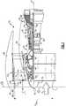
- FIG. 1schematically illustrates an example gas turbine engine 20 that includes a fan section 22, a compressor section 24, a combustor section 26 and a turbine section 28.
- Alternative enginesmight include an augmenter section (not shown) among other systems or features.
- the fan section 22drives air along a bypass flow path B while the compressor section 24 draws air in along a core flow path C where air is compressed and communicated to a combustor section 26.
- airis mixed with fuel and ignited to generate a high pressure exhaust gas stream that expands through the turbine section 28 where energy is extracted and utilized to drive the fan section 22 and the compressor section 24.
- turbofan gas turbine enginedepicts a turbofan gas turbine engine
- the concepts described hereinare not limited to use with turbofans as the teachings may be applied to other types of turbine engines; for example a turbine engine including a three-spool architecture in which three spools concentrically rotate about a common axis and where a low spool enables a low pressure turbine to drive a fan via a gearbox, an intermediate spool that enables an intermediate pressure turbine to drive a first compressor of the compressor section, and a high spool that enables a high pressure turbine to drive a high pressure compressor of the compressor section.
- the example engine 20generally includes a low speed spool 30 and a high speed spool 32 mounted for rotation about an engine central longitudinal axis X relative to an engine static structure 36 via several bearing systems 38. It should be understood that various bearing systems 38 at various locations may alternatively or additionally be provided.
- the low speed spool 30generally includes an inner shaft 40 that connects a having fan blades 42 and a low pressure (or first) compressor section 44 to a low pressure (or first) turbine section 46.
- the inner shaft 40drives the fan blades 42 through a speed change device, such as a geared architecture 48, to drive the fan blades 42 at a lower speed than the low speed spool 30.
- the high-speed spool 32includes an outer shaft 50 that interconnects a high pressure (or second) compressor section 52 and a high pressure (or second) turbine section 54.
- the inner shaft 40 and the outer shaft 50are concentric and rotate via the bearing systems 38 about the engine central longitudinal axis X.
- a combustor 56is arranged between the high pressure compressor 52 and the high pressure turbine 54.
- the high pressure turbine 54includes at least two stages to provide a double stage high pressure turbine 54.
- the high pressure turbine 54includes only a single stage.
- a "high pressure" compressor or turbineexperiences a higher pressure than a corresponding "low pressure” compressor or turbine.
- the example low pressure turbine 46has a pressure ratio that is greater than about 5.
- the pressure ratio of the example low pressure turbine 46is measured prior to an inlet of the low pressure turbine 46 as related to the pressure measured at the outlet of the low pressure turbine 46 prior to an exhaust nozzle.
- a mid-turbine frame 57 of the engine static structure 36is arranged generally between the high pressure turbine 54 and the low pressure turbine 46.
- the mid-turbine frame 57further supports bearing systems 38 in the turbine section 28 as well as setting airflow entering the low pressure turbine 46.
- the core airflow Cis compressed by the low pressure compressor 44 then by the high pressure compressor 52 mixed with fuel and ignited in the combustor 56 to produce high speed exhaust gases that are then expanded through the high pressure turbine 54 and low pressure turbine 46.
- the mid-turbine frame 57includes vanes 59, which are in the core airflow path and function as an inlet guide vane for the low pressure turbine 46. Utilizing the vane 59 of the mid-turbine frame 57 as the inlet guide vane for low pressure turbine 46 decreases the length of the low pressure turbine 46 without increasing the axial length of the mid-turbine frame 57. Reducing or eliminating the number of vanes in the low pressure turbine 46 shortens the axial length of the turbine section 28. Thus, the compactness of the gas turbine engine 20 is increased and a higher power density may be achieved.
- the disclosed gas turbine engine 20 in one exampleis a high-bypass geared aircraft engine.
- the gas turbine engine 20includes a bypass ratio greater than about six, with an example embodiment being greater than about ten.
- the example geared architecture 48is an epicyclical gear train, such as a planetary gear system, star gear system or other known gear system, with a gear reduction ratio of greater than about 2.3.
- the gas turbine engine 20includes a bypass ratio greater than about ten and the fan diameter is significantly larger than an outer diameter of the low pressure compressor 44. It should be understood, however, that the above parameters are only exemplary of one embodiment of a gas turbine engine including a geared architecture and that the present disclosure is applicable to other gas turbine engines.
- the fan section 22 of the engine 20is designed for a particular flight condition -- typically cruise at about 0.8 Mach and about 35,000 feet (10,668 m).
- the flight condition of 0.8 Mach and 35,000 ft. (10,668 m), with the engine at its best fuel consumption - also known as "bucket cruise Thrust Specific Fuel Consumption ('TSFC')" -is the industry standard parameter of pound-mass (lbm) of fuel per hour being burned divided by pound-force (lbf) of thrust the engine produces at that minimum point.
- Low fan pressure ratiois the pressure ratio across the fan blade alone, without a Fan Exit Guide Vane (“FEGV”) system.
- the low fan pressure ratio as disclosed herein according to one non-limiting embodimentis less than about 1.50. In another non-limiting embodiment the low fan pressure ratio is less than about 1.45.
- the "Low corrected fan tip speed”, as disclosed herein according to one non-limiting embodiment,is less than about 1150 ft/second (350.5 m/s).
- the bypass flow path Bis provided radially between a fan nacelle 60 and core nacelle 62.
- the fan nacelle 60includes an inlet 64 that receives an inlet flow I into the engine 20.
- the inlet 64includes an inner surface 66 that provides an annular shape having a throat 76 in plane B, which is the minimum cross-sectional area of the inlet 64 without a spinner 70 installed.
- the throat 76is arranged upstream from the fan blades 42.
- the fan blades 42include a fan leading edge 68 having a leading edge forward-most point 69.
- the fan blades 42have an outer diameter D fan .
- the leading edge forward-most point 69is spaced a length L1 from an inlet forward-most point 65 of the inlet 64 (in plane A).
- the fan blades 42are supported by a fan hub 72, which is rotationally driven through a fan shaft 80 coupled to the geared architecture 48.
- the spinner 70is mounted to the fan hub 72 upstream from the fan blades 42 to provide an aerodynamic inner flow path to the fan section 22.
- the L1/D fan ratio (sometimes referred to as an "L/D ratio”) of the engine 20is less than or equal to about 0.4, and in one example, about 0.3.
- the term "about”means +/-0.05.
- the spinner 70includes a spinner forward-most point 74, which is arranged significantly forward within the inlet 64 than a typical high bypass ratio engine. In the example illustrated, the spinner forward-most point 74 is arranged forward of the plane 78. The spinner forward-most point 74 does not extend forward of the inlet forward-most point 65.
- the engine 20has a relatively large diameter fan section 22, which adds weight to the engine 20.
- One way of reducing the weight of the engine 20is to reduce the nacelle inlet length L1.
- a short inlettypically results in inlet lip flow separation under a high angle of attack, which results in a reduction of the efficiency of the fan section 22 and resulting in a corresponding reduction of the engine's thrust.
- the spinner 70is moved forward. With a forwardly-located spinner, the pressure at the nacelle inlet lip and inner surface 66 will reduce the shock at crosswind conditions and at high angles of attack when the engine is at full power.
- the gas turbine engine inlet 64has a relatively short inlet and fan spinner such that the length of the spinner L2 is equal to or greater than half the overall length of the inlet L1, as shown in Figure 3a .
- the ratio of spinner length to overall inlet length, L2/L1is about 0.65 and the leading edge 74 of the spinner 70 is located at the throat 76 of the inlet 64.
- the internal area distributionis monotonically convergent from the inlet leading edge to the fan face, as shown in Figure 3b .
- a monotonically convergent internal area distributionis favorable to good aerodynamic performance of the gas turbine engine inlet at conditions of low flight speed and high engine power, particularly at high aircraft angle of attack or in crosswind operation.
Landscapes
- Engineering & Computer Science (AREA)
- Chemical & Material Sciences (AREA)
- Combustion & Propulsion (AREA)
- Mechanical Engineering (AREA)
- General Engineering & Computer Science (AREA)
- Structures Of Non-Positive Displacement Pumps (AREA)
Description
- This disclosure relates to a gas turbine engine inlet. More particularly, the disclosure relates to a relative position of a fan and a spinner relative to a fan nacelle inlet.
- A gas turbine engine typically includes a fan section, a compressor section, a combustor section and a turbine section. Air entering the compressor section is compressed and delivered into the combustor section where it is mixed with fuel and ignited to generate a high-speed exhaust gas flow. The high-speed exhaust gas flow expands through the turbine section to drive the compressor and the fan section. The compressor section typically includes low and high pressure compressors, and the turbine section includes low and high pressure turbines.
- One type of gas turbine engine includes a fan drive gear system having a fan section with relatively large fan blades. One type of gas turbine engine utilizes a high bypass flow to provide a significant portion of thrust from a fan arranged in the bypass flow path, which extends from an inlet of the gas turbine engine.
- The inlet may be cambered such that a plane that is tangent to the inlet leading edge is tilted or drooped relative to the engine centerline, as shown by plane A in
Figure 2a . The angle of inlet droop may be in the range zero to six degrees, with the inlet tilted downward so that the inlet length at the top is longer than the length at the bottom. It is also known to have negative droop or negative scarf inlet designs such that the inlet length at the bottom extends furthest forward. - Inlet throat is defined at an axial position (at plane B) within the inlet that has a local minimum area normal to the flow direction. A plane located at the throat (plane B) may be tilted relative to the engine axis, similar to the inlet leading edge plane (plane A).
- An inlet length (L1) is defined from the midpoint of the inlet leading edge plane A at
inlet leading edge 165 to fan face plane C at the leadingedge 169 of thefan 142, where plane C is taken perpendicular to the engine axis at the axial position of the fan blade tip leading edge. The ratio of inlet length L1 to fan leading edge tip diameter, L1/Dfan, is generally in the range 0.5 to 0.7 in typical inlet systems on high bypass ratio turbofan engines. - A
fan spinner 170 forms the inner flowpath through the fan blade. The diameter of the spinner at the fan hub leading edge corresponds to Ds inFigure 2A . The hub/tip ratio of the fan, Ds/Dfan, is generally about 0.3 and may be in the range 0.25 to 0.35. The spinner may have a pointed leading edge with a generally conical shape, or it may have a blunt rounded leading edge shape. The axial length of the spinner from its leading edge to fan face plane C corresponds to L2. The ratio of spinner length to overall inlet length, L2/L1, is less than 0.5 in a typical gas turbine engine inlet on high bypass turbofan engines. - A typical internal area distribution for the gas turbine engine inlet is shown in
Figure 2b , normalized to the flow area at the fan face, Afan = π/4 (Dfan2 - Ds2). There is a local minimum area at the inlet throat plane B, followed by a diffusing section from thethroat 176 to the leadingedge 174 of thefan spinner 170 in which the flow area increases, then there is a convergent section beginning approximately at thespinner leading edge 174 to the fan face (plane C) in which the flow area decreases due to the area blockage of thespinner 170. - A prior art gas turbine engine, having the features of the preamble of
claim 1, is disclosed inUS2010/0215479 . Further prior art gas turbine engines are disclosed inGB-1190364 FR-2958974 - According to the present invention, there is provided a gas turbine engine as claimed in
claim 1. - An embodiment of the above includes a plane at the throat and a fan hub supporting the fan. A spinner is mounted on the fan hub forward of the fan. At least a portion of the spinner is arranged forward of the plane.
- In a further embodiment of any of the above, a spinner forward-most point is arranged forward of the plane.
- In a further embodiment of any of the above, the ratio is about 0.65
- In a further embodiment of any of the above, the inlet length extends from a fan blade leading edge forward-most point to the inlet forward-most point.
- In a further embodiment of any of the above, the fan includes a diameter. The ratio of the inlet length to diameter is equal to or less than about 0.4.
- In a further embodiment of any of the above, the ratio of the inlet length to the diameter is about 0.3.
- In a further embodiment of any of the above, the gas turbine engine includes a compressor section fluidly connected to the fan. The compressor includes a high pressure compressor and a low pressure compressor. A combustor is fluidly connected to the compressor section. A turbine section is fluidly connected to the combustor. The turbine section includes a high pressure turbine coupled to the high pressure compressor via a shaft and a low pressure turbine.
- In a further embodiment of any of the above, the gas turbine engine includes a geared architecture that operatively interconnects the turbine section to the fan.
- In a further embodiment of any of the above, the gas turbine engine is a high bypass geared aircraft engine that has a bypass ratio of greater than six.
- In a further embodiment of any of the above, the gas turbine engine includes a Fan Pressure Ratio of less than 1.45.
- In a further embodiment of any of the above, the low pressure turbine has a pressure ratio that is greater than 5.
- The disclosure can be further understood by reference to the following detailed description when considered in connection with the accompanying drawings wherein:
Figure 1 schematically illustrates a gas turbine engine embodiment.Figure 2a schematically illustrates a prior art fan and inlet arrangement.Figure 2b graphically depicts an internal area distribution from the inlet leading edge to a fan face for the fan and inlet arrangement ofFigure 2a .Figure 3a schematically illustrates an example fan and inlet arrangement.Figure 3b graphically depicts an internal area distribution from the inlet leading edge to a fan face for the fan and inlet arrangement ofFigure 3a .Figure 1 schematically illustrates an examplegas turbine engine 20 that includes afan section 22, acompressor section 24, acombustor section 26 and aturbine section 28. Alternative engines might include an augmenter section (not shown) among other systems or features. Thefan section 22 drives air along a bypass flow path B while thecompressor section 24 draws air in along a core flow path C where air is compressed and communicated to acombustor section 26. In thecombustor section 26, air is mixed with fuel and ignited to generate a high pressure exhaust gas stream that expands through theturbine section 28 where energy is extracted and utilized to drive thefan section 22 and thecompressor section 24.- Although the disclosed non-limiting embodiment depicts a turbofan gas turbine engine, it should be understood that the concepts described herein are not limited to use with turbofans as the teachings may be applied to other types of turbine engines; for example a turbine engine including a three-spool architecture in which three spools concentrically rotate about a common axis and where a low spool enables a low pressure turbine to drive a fan via a gearbox, an intermediate spool that enables an intermediate pressure turbine to drive a first compressor of the compressor section, and a high spool that enables a high pressure turbine to drive a high pressure compressor of the compressor section.
- The
example engine 20 generally includes alow speed spool 30 and ahigh speed spool 32 mounted for rotation about an engine central longitudinal axis X relative to an enginestatic structure 36 viaseveral bearing systems 38. It should be understood thatvarious bearing systems 38 at various locations may alternatively or additionally be provided. - The
low speed spool 30 generally includes aninner shaft 40 that connects a havingfan blades 42 and a low pressure (or first) compressor section 44 to a low pressure (or first)turbine section 46. Theinner shaft 40 drives thefan blades 42 through a speed change device, such as a gearedarchitecture 48, to drive thefan blades 42 at a lower speed than thelow speed spool 30. The high-speed spool 32 includes anouter shaft 50 that interconnects a high pressure (or second)compressor section 52 and a high pressure (or second) turbine section 54. Theinner shaft 40 and theouter shaft 50 are concentric and rotate via the bearingsystems 38 about the engine central longitudinal axis X. - A
combustor 56 is arranged between thehigh pressure compressor 52 and the high pressure turbine 54. In one example, the high pressure turbine 54 includes at least two stages to provide a double stage high pressure turbine 54. In another example, the high pressure turbine 54 includes only a single stage. As used herein, a "high pressure" compressor or turbine experiences a higher pressure than a corresponding "low pressure" compressor or turbine. - The example
low pressure turbine 46 has a pressure ratio that is greater than about 5. The pressure ratio of the examplelow pressure turbine 46 is measured prior to an inlet of thelow pressure turbine 46 as related to the pressure measured at the outlet of thelow pressure turbine 46 prior to an exhaust nozzle. - A mid-turbine frame 57 of the engine
static structure 36 is arranged generally between the high pressure turbine 54 and thelow pressure turbine 46. The mid-turbine frame 57 furthersupports bearing systems 38 in theturbine section 28 as well as setting airflow entering thelow pressure turbine 46. - The core airflow C is compressed by the low pressure compressor 44 then by the
high pressure compressor 52 mixed with fuel and ignited in thecombustor 56 to produce high speed exhaust gases that are then expanded through the high pressure turbine 54 andlow pressure turbine 46. The mid-turbine frame 57 includesvanes 59, which are in the core airflow path and function as an inlet guide vane for thelow pressure turbine 46. Utilizing thevane 59 of the mid-turbine frame 57 as the inlet guide vane forlow pressure turbine 46 decreases the length of thelow pressure turbine 46 without increasing the axial length of the mid-turbine frame 57. Reducing or eliminating the number of vanes in thelow pressure turbine 46 shortens the axial length of theturbine section 28. Thus, the compactness of thegas turbine engine 20 is increased and a higher power density may be achieved. - The disclosed
gas turbine engine 20 in one example is a high-bypass geared aircraft engine. In a further example, thegas turbine engine 20 includes a bypass ratio greater than about six, with an example embodiment being greater than about ten. The example gearedarchitecture 48 is an epicyclical gear train, such as a planetary gear system, star gear system or other known gear system, with a gear reduction ratio of greater than about 2.3. - In one disclosed embodiment, the
gas turbine engine 20 includes a bypass ratio greater than about ten and the fan diameter is significantly larger than an outer diameter of the low pressure compressor 44. It should be understood, however, that the above parameters are only exemplary of one embodiment of a gas turbine engine including a geared architecture and that the present disclosure is applicable to other gas turbine engines. - A significant amount of thrust is provided by the bypass flow B due to the high bypass ratio. The
fan section 22 of theengine 20 is designed for a particular flight condition -- typically cruise at about 0.8 Mach and about 35,000 feet (10,668 m). The flight condition of 0.8 Mach and 35,000 ft. (10,668 m), with the engine at its best fuel consumption - also known as "bucket cruise Thrust Specific Fuel Consumption ('TSFC')" - is the industry standard parameter of pound-mass (lbm) of fuel per hour being burned divided by pound-force (lbf) of thrust the engine produces at that minimum point. - "Low fan pressure ratio" is the pressure ratio across the fan blade alone, without a Fan Exit Guide Vane ("FEGV") system. The low fan pressure ratio as disclosed herein according to one non-limiting embodiment is less than about 1.50. In another non-limiting embodiment the low fan pressure ratio is less than about 1.45.
- "Low corrected fan tip speed" is the actual fan tip speed in ft/sec divided by an industry standard temperature correction of [(Tram °R) / (518.7 °R)]0.5 (where °R = K x 9/5). The "Low corrected fan tip speed", as disclosed herein according to one non-limiting embodiment, is less than about 1150 ft/second (350.5 m/s).
- The bypass flow path B is provided radially between a
fan nacelle 60 andcore nacelle 62. Thefan nacelle 60 includes aninlet 64 that receives an inlet flow I into theengine 20. Theinlet 64 includes aninner surface 66 that provides an annular shape having athroat 76 in plane B, which is the minimum cross-sectional area of theinlet 64 without aspinner 70 installed. Thethroat 76 is arranged upstream from thefan blades 42. - The
fan blades 42 include afan leading edge 68 having a leading edgeforward-most point 69. Thefan blades 42 have an outer diameter Dfan. The leading edgeforward-most point 69 is spaced a length L1 from an inletforward-most point 65 of the inlet 64 (in plane A). - The
fan blades 42 are supported by afan hub 72, which is rotationally driven through afan shaft 80 coupled to the gearedarchitecture 48. Thespinner 70 is mounted to thefan hub 72 upstream from thefan blades 42 to provide an aerodynamic inner flow path to thefan section 22. - The L1/Dfan ratio (sometimes referred to as an "L/D ratio") of the
engine 20 is less than or equal to about 0.4, and in one example, about 0.3. The term "about" means +/-0.05. Thespinner 70 includes a spinnerforward-most point 74, which is arranged significantly forward within theinlet 64 than a typical high bypass ratio engine. In the example illustrated, the spinnerforward-most point 74 is arranged forward of the plane 78. The spinnerforward-most point 74 does not extend forward of the inletforward-most point 65. - The
engine 20 has a relatively largediameter fan section 22, which adds weight to theengine 20. One way of reducing the weight of theengine 20 is to reduce the nacelle inlet length L1. However, a short inlet typically results in inlet lip flow separation under a high angle of attack, which results in a reduction of the efficiency of thefan section 22 and resulting in a corresponding reduction of the engine's thrust. To reduce the tendency for the flow to separate when using a short length LI, thespinner 70 is moved forward. With a forwardly-located spinner, the pressure at the nacelle inlet lip andinner surface 66 will reduce the shock at crosswind conditions and at high angles of attack when the engine is at full power. - The gas
turbine engine inlet 64 has a relatively short inlet and fan spinner such that the length of the spinner L2 is equal to or greater than half the overall length of the inlet L1, as shown inFigure 3a . In one example embodiment, the ratio of spinner length to overall inlet length, L2/L1, is about 0.65 and the leadingedge 74 of thespinner 70 is located at thethroat 76 of theinlet 64. - In this manner the effect of the area blockage of the fan spinner occurs at or immediately behind the
throat 76, thus there is no local minimum internal area at thethroat 76 and there is no diffusing section in the internal area distribution. The internal area distribution is monotonically convergent from the inlet leading edge to the fan face, as shown inFigure 3b . A monotonically convergent internal area distribution is favorable to good aerodynamic performance of the gas turbine engine inlet at conditions of low flight speed and high engine power, particularly at high aircraft angle of attack or in crosswind operation.
Claims (12)
- A gas turbine engine (20) comprising:a fan nacelle (60) and a core nacelle (65) providing a bypass flow path (B) radially between, the fan nacelle (60) having an inlet (64) including a throat (76), the inlet (64) having an inlet forward-most point (65);a fan (22) arranged in the bypass flow path (B) and rotatable about an axis (X), the fan (22) having a leading edge (68) recessed from the inlet forward-most point (65) by an inlet length (L1) in an axial direction;a spinner (70) having a spinner length (L2) from a spinner forward-most point (74) to the leading edge (68); the spinner forward-most point (74) does not extend forward of the inlet forward-most point (65); and an area is provided between the fan nacelle (60) and the spinner (70),characterised in that
the area is monotonically convergent from the inlet (64) to the fan (22); anda ratio of the spinner length to inlet length (L2/L1) is equal to or greater than 0.5. - The gas turbine engine (20) according to claim 1, comprising a plane (B) at the throat (76) and a fan hub (72) supporting the fan (22), and a spinner (70) mounted on the fan hub (72) forward of the fan (22), at least a portion of the spinner (70) arranged forward of the plane (B).
- The gas turbine engine (20) according to claim 2, wherein the spinner forward-most point (74) is arranged forward of the plane (B).
- The gas turbine engine (20) according to any preceding claim, wherein the ratio is 0.65
- The gas turbine engine (20) according to any preceding claim, wherein the inlet length (L1) extends from a fan blade leading edge forward-most point (69) to the inlet forward-most point (65).
- The gas turbine engine (20) according to any preceding claim, wherein the fan (22) includes a diameter, and a ratio of the inlet length (L1) to diameter is equal to or less than about 0.4.
- The gas turbine engine (20) according to claim 6, wherein the ratio of the inlet length (L1) to the diameter is about 0.3.
- The gas turbine engine (20) according to any preceding claim, further comprising:a compressor section (24) fluidly connected to the fan (22) and comprising a high pressure compressor (52) and a low pressure compressor (44);a combustor (56) fluidly connected to the compressor section (24);a turbine section (28) fluidly connected to the combustor (56) and comprising a high pressure turbine (54) coupled to the high pressure compressor (52) via a shaft (32) and
a low pressure turbine (46). - The gas turbine engine (20) according to claim 8, comprising a geared architecture (48) operatively interconnecting the turbine section (28) to the fan (22).
- The gas turbine engine (20) according to claim 9, wherein the gas turbine engine (20) is a high bypass geared aircraft engine having a bypass ratio of greater than six.
- The gas turbine engine (20) according to claim 8, 9 or 10, wherein the gas turbine engine (20) includes a Fan Pressure Ratio of less than 1.45.
- The gas turbine engine (20) according to any of claims 8 to 11, wherein the low pressure turbine (46) has a pressure ratio that is greater than five.
Priority Applications (1)
| Application Number | Priority Date | Filing Date | Title |
|---|---|---|---|
| EP19174038.0AEP3564507B1 (en) | 2013-03-04 | 2014-02-26 | Gas turbine engine inlet |
Applications Claiming Priority (2)
| Application Number | Priority Date | Filing Date | Title |
|---|---|---|---|
| US201361772460P | 2013-03-04 | 2013-03-04 | |
| PCT/US2014/018544WO2014137685A1 (en) | 2013-03-04 | 2014-02-26 | Gas turbine engine inlet |
Related Child Applications (1)
| Application Number | Title | Priority Date | Filing Date |
|---|---|---|---|
| EP19174038.0ADivisionEP3564507B1 (en) | 2013-03-04 | 2014-02-26 | Gas turbine engine inlet |
Publications (3)
| Publication Number | Publication Date |
|---|---|
| EP2964924A1 EP2964924A1 (en) | 2016-01-13 |
| EP2964924A4 EP2964924A4 (en) | 2016-11-09 |
| EP2964924B1true EP2964924B1 (en) | 2019-05-15 |
Family
ID=51491786
Family Applications (2)
| Application Number | Title | Priority Date | Filing Date |
|---|---|---|---|
| EP14759888.2AActiveEP2964924B1 (en) | 2013-03-04 | 2014-02-26 | Gas turbine engine inlet |
| EP19174038.0AActiveEP3564507B1 (en) | 2013-03-04 | 2014-02-26 | Gas turbine engine inlet |
Family Applications After (1)
| Application Number | Title | Priority Date | Filing Date |
|---|---|---|---|
| EP19174038.0AActiveEP3564507B1 (en) | 2013-03-04 | 2014-02-26 | Gas turbine engine inlet |
Country Status (3)
| Country | Link |
|---|---|
| US (2) | US11480104B2 (en) |
| EP (2) | EP2964924B1 (en) |
| WO (1) | WO2014137685A1 (en) |
Cited By (1)
| Publication number | Priority date | Publication date | Assignee | Title |
|---|---|---|---|---|
| EP3543512B1 (en)* | 2013-09-30 | 2024-12-11 | RTX Corporation | Turbofan engine having a dimensional relationship between inlet and fan size |
Families Citing this family (33)
| Publication number | Priority date | Publication date | Assignee | Title |
|---|---|---|---|---|
| US20160108854A1 (en)* | 2012-12-20 | 2016-04-21 | United Technologies Corporation | Low pressure ratio fan engine having a dimensional relationship between inlet and fan size |
| US9920653B2 (en) | 2012-12-20 | 2018-03-20 | United Technologies Corporation | Low pressure ratio fan engine having a dimensional relationship between inlet and fan size |
| EP3156627A1 (en)* | 2015-10-14 | 2017-04-19 | United Technologies Corporation | Low pressure ratio fan engine having a dimensional relationship between inlet and fan size |
| US10167088B2 (en)* | 2015-10-19 | 2019-01-01 | General Electric Company | Crosswind performance aircraft engine spinner |
| US20170175626A1 (en)* | 2015-12-18 | 2017-06-22 | United Technologies Corporation | Gas turbine engine with minimized inlet distortion |
| US10823192B2 (en) | 2015-12-18 | 2020-11-03 | Raytheon Technologies Corporation | Gas turbine engine with short inlet and mistuned fan blades |
| US10794398B2 (en) | 2015-12-18 | 2020-10-06 | Raytheon Technologies Corporation | Gas turbine engine with one piece acoustic treatment |
| US20170175766A1 (en)* | 2015-12-18 | 2017-06-22 | United Technologies Corporation | Gas turbine engine with rotating inlet |
| US10731661B2 (en) | 2015-12-18 | 2020-08-04 | Raytheon Technologies Corporation | Gas turbine engine with short inlet and blade removal feature |
| US10823060B2 (en) | 2015-12-18 | 2020-11-03 | Raytheon Technologies Corporation | Gas turbine engine with short inlet, acoustic treatment and anti-icing features |
| US10479519B2 (en)* | 2015-12-31 | 2019-11-19 | United Technologies Corporation | Nacelle short inlet for fan blade removal |
| EP3214298A1 (en)* | 2016-03-03 | 2017-09-06 | Alpha Velorum AG | Improved turbofan engine |
| US10208709B2 (en) | 2016-04-05 | 2019-02-19 | United Technologies Corporation | Fan blade removal feature for a gas turbine engine |
| FR3068735B1 (en)* | 2017-07-06 | 2019-07-26 | Safran Aircraft Engines | TURBOREACTOR WITH LOW NOISE OF BLOW |
| GB201712993D0 (en)* | 2017-08-14 | 2017-09-27 | Rolls Royce Plc | Gas turbine engine |
| US10974813B2 (en)* | 2018-01-08 | 2021-04-13 | General Electric Company | Engine nacelle for an aircraft |
| US10436035B1 (en)* | 2018-07-03 | 2019-10-08 | Rolls-Royce Plc | Fan design |
| GB201820941D0 (en) | 2018-12-21 | 2019-02-06 | Rolls Royce Plc | Low noise gas turbine engine |
| GB201820934D0 (en)* | 2018-12-21 | 2019-02-06 | Rolls Royce Plc | Low fan noise geared gas turbine engine |
| GB201820936D0 (en)* | 2018-12-21 | 2019-02-06 | Rolls Royce Plc | Low noise gas turbine engine |
| GB201820943D0 (en) | 2018-12-21 | 2019-02-06 | Rolls Royce Plc | Gas turbine engine having improved noise signature |
| GB201820945D0 (en) | 2018-12-21 | 2019-02-06 | Rolls Royce Plc | Low noise gas turbine engine |
| US10815895B2 (en) | 2018-12-21 | 2020-10-27 | Rolls-Royce Plc | Gas turbine engine with differing effective perceived noise levels at differing reference points and methods for operating gas turbine engine |
| GB201820940D0 (en) | 2018-12-21 | 2019-02-06 | Rolls Royce Plc | Low noise gas turbine engine |
| GB201903261D0 (en) | 2019-03-11 | 2019-04-24 | Rolls Royce Plc | Efficient gas turbine engine installation and operation |
| GB201903257D0 (en)* | 2019-03-11 | 2019-04-24 | Rolls Royce Plc | Efficient gas turbine engine installation and operation |
| GB201903262D0 (en) | 2019-03-11 | 2019-04-24 | Rolls Royce Plc | Efficient gas turbine engine installation and operation |
| GB201912441D0 (en)* | 2019-08-30 | 2019-10-16 | Rolls Royce Plc | A gas turbine engine for an aircraft comprising an air intake |
| GB201912822D0 (en)* | 2019-09-06 | 2019-10-23 | Rolls Royce Plc | Gas turbine engine |
| GB201917415D0 (en)* | 2019-11-29 | 2020-01-15 | Rolls Royce Plc | Nacelle for a gas turbine engine |
| GB202007010D0 (en)* | 2020-05-13 | 2020-06-24 | Rolls Royce Plc | Nacelle for gas turbine engine |
| US11480073B2 (en)* | 2020-11-24 | 2022-10-25 | Rolls-Royce Plc | Gas turbine engine nacelle and method of designing same |
| GB202018497D0 (en) | 2020-11-25 | 2021-01-06 | Rolls Royce Plc | Aircraft engine |
Family Cites Families (30)
| Publication number | Priority date | Publication date | Assignee | Title |
|---|---|---|---|---|
| US3222863A (en)* | 1963-10-07 | 1965-12-14 | Boeing Co | Aerodynamic inlet |
| GB1190364A (en)* | 1966-04-12 | 1970-05-06 | Dowty Rotol Ltd | Gas Turbine Engines |
| US3546882A (en)* | 1968-04-24 | 1970-12-15 | Gen Electric | Gas turbine engines |
| GB1312619A (en)* | 1969-10-03 | 1973-04-04 | Secr Defence | Air intakes for gas turbine engines |
| GB1382809A (en)* | 1971-12-04 | 1975-02-05 | Rolls Royce | Air intakes for gas turbine engines |
| US3946830A (en) | 1974-09-06 | 1976-03-30 | General Electric Company | Inlet noise deflector |
| GB1524908A (en)* | 1976-06-01 | 1978-09-13 | Rolls Royce | Gas turbine engine with anti-icing facility |
| US4142365A (en)* | 1976-11-01 | 1979-03-06 | General Electric Company | Hybrid mixer for a high bypass ratio gas turbofan engine |
| US4240250A (en)* | 1977-12-27 | 1980-12-23 | The Boeing Company | Noise reducing air inlet for gas turbine engines |
| US5058617A (en)* | 1990-07-23 | 1991-10-22 | General Electric Company | Nacelle inlet for an aircraft gas turbine engine |
| GB9025023D0 (en)* | 1990-11-16 | 1991-01-02 | Rolls Royce Plc | Engine nacelle |
| GB2259114A (en) | 1991-08-28 | 1993-03-03 | Gen Electric | Aircraft engine nacelle profile |
| CA2072417A1 (en) | 1991-08-28 | 1993-03-01 | David E. Yates | Aircraft engine nacelle having circular arc profile |
| US5915403A (en) | 1998-04-14 | 1999-06-29 | The Boeing Company | Biplanar scarfed nacelle inlet |
| US20040187475A1 (en)* | 2002-11-12 | 2004-09-30 | Usab William J. | Apparatus and method for reducing radiated sound produced by a rotating impeller |
| GB2400411B (en) | 2003-04-10 | 2006-09-06 | Rolls Royce Plc | Turbofan arrangement |
| US20050274103A1 (en)* | 2004-06-10 | 2005-12-15 | United Technologies Corporation | Gas turbine engine inlet with noise reduction features |
| FR2873751B1 (en)* | 2004-07-28 | 2006-09-29 | Snecma Moteurs Sa | INPUT CONE OF A TURBOMACHINE |
| US7309210B2 (en)* | 2004-12-17 | 2007-12-18 | United Technologies Corporation | Turbine engine rotor stack |
| US8568101B2 (en)* | 2007-03-27 | 2013-10-29 | Ihi Corporation | Fan rotor blade support structure and turbofan engine having the same |
| US8727267B2 (en) | 2007-05-18 | 2014-05-20 | United Technologies Corporation | Variable contraction ratio nacelle assembly for a gas turbine engine |
| US20080310956A1 (en)* | 2007-06-13 | 2008-12-18 | Jain Ashok K | Variable geometry gas turbine engine nacelle assembly with nanoelectromechanical system |
| US8459035B2 (en)* | 2007-07-27 | 2013-06-11 | United Technologies Corporation | Gas turbine engine with low fan pressure ratio |
| GB0813483D0 (en)* | 2008-07-24 | 2008-08-27 | Rolls Royce Plc | Gas turbine engine nacelle |
| FR2938504B1 (en)* | 2008-11-14 | 2010-12-10 | Snecma | AIR INTAKE OF AN AIRCRAFT ENGINE WITH NON-CARINE PROPELLANT PROPELLERS |
| US20110167792A1 (en)* | 2009-09-25 | 2011-07-14 | James Edward Johnson | Adaptive engine |
| FR2958974B1 (en) | 2010-04-16 | 2016-06-10 | Snecma | GAS TURBINE ENGINE PROVIDED WITH AN AIR-OIL HEAT EXCHANGER IN ITS AIR INLET HANDLE |
| FR2960028B1 (en)* | 2010-05-12 | 2016-07-15 | Snecma | DEVICE FOR ATTENUATING THE NOISE EMITTED BY THE JET OF A PROPULSION ENGINE OF AN AIRCRAFT. |
| US20130192256A1 (en)* | 2012-01-31 | 2013-08-01 | Gabriel L. Suciu | Geared turbofan engine with counter-rotating shafts |
| US20130195647A1 (en)* | 2012-01-31 | 2013-08-01 | Marc J. Muldoon | Gas turbine engine bearing arrangement including aft bearing hub geometry |
- 2014
- 2014-02-26USUS14/767,396patent/US11480104B2/enactiveActive
- 2014-02-26WOPCT/US2014/018544patent/WO2014137685A1/enactiveApplication Filing
- 2014-02-26EPEP14759888.2Apatent/EP2964924B1/enactiveActive
- 2014-02-26EPEP19174038.0Apatent/EP3564507B1/enactiveActive
- 2022
- 2022-10-02USUS17/958,405patent/US20230025200A1/enactivePending
Non-Patent Citations (1)
| Title |
|---|
| None* |
Cited By (1)
| Publication number | Priority date | Publication date | Assignee | Title |
|---|---|---|---|---|
| EP3543512B1 (en)* | 2013-09-30 | 2024-12-11 | RTX Corporation | Turbofan engine having a dimensional relationship between inlet and fan size |
Also Published As
| Publication number | Publication date |
|---|---|
| US11480104B2 (en) | 2022-10-25 |
| EP2964924A4 (en) | 2016-11-09 |
| EP3564507A1 (en) | 2019-11-06 |
| US20230025200A1 (en) | 2023-01-26 |
| WO2014137685A1 (en) | 2014-09-12 |
| EP3564507B1 (en) | 2022-04-13 |
| US20160003145A1 (en) | 2016-01-07 |
| EP2964924A1 (en) | 2016-01-13 |
Similar Documents
| Publication | Publication Date | Title |
|---|---|---|
| US20230025200A1 (en) | Gas turbine engine inlet | |
| US10738627B2 (en) | Geared low fan pressure ratio fan exit guide vane stagger angle | |
| US10808621B2 (en) | Gas turbine engine having support structure with swept leading edge | |
| EP3187712B1 (en) | Nacelle short inlet | |
| EP3187722B1 (en) | Nacelle short inlet for fan blade removal | |
| US11585293B2 (en) | Low weight large fan gas turbine engine | |
| US20130283821A1 (en) | Gas turbine engine and nacelle noise attenuation structure | |
| EP2809929B1 (en) | High turning fan exit stator | |
| EP3019728B1 (en) | Three spool geared turbofan with low pressure compressor drive gear system | |
| EP3036422A1 (en) | High performance convergent divergent nozzle | |
| EP2904239B1 (en) | Assembly comprising a geared turbofan, a pylon and a wing | |
| EP3094823B1 (en) | Gas turbine engine component and corresponding gas turbine engine | |
| US11073087B2 (en) | Gas turbine engine variable pitch fan blade | |
| EP2904252B1 (en) | Static guide vane with internal hollow channels | |
| US20140083079A1 (en) | Geared turbofan primary and secondary nozzle integration geometry | |
| US20140212261A1 (en) | Lightweight shrouded fan | |
| EP3181863B1 (en) | Gas turbine engine with minimized inlet distortion | |
| US10731661B2 (en) | Gas turbine engine with short inlet and blade removal feature |
Legal Events
| Date | Code | Title | Description |
|---|---|---|---|
| PUAI | Public reference made under article 153(3) epc to a published international application that has entered the european phase | Free format text:ORIGINAL CODE: 0009012 | |
| 17P | Request for examination filed | Effective date:20150930 | |
| AK | Designated contracting states | Kind code of ref document:A1 Designated state(s):AL AT BE BG CH CY CZ DE DK EE ES FI FR GB GR HR HU IE IS IT LI LT LU LV MC MK MT NL NO PL PT RO RS SE SI SK SM TR | |
| AX | Request for extension of the european patent | Extension state:BA ME | |
| DAX | Request for extension of the european patent (deleted) | ||
| RAP1 | Party data changed (applicant data changed or rights of an application transferred) | Owner name:UNITED TECHNOLOGIES CORPORATION | |
| A4 | Supplementary search report drawn up and despatched | Effective date:20161010 | |
| RIC1 | Information provided on ipc code assigned before grant | Ipc:F02C 7/04 20060101AFI20161004BHEP Ipc:F02K 3/06 20060101ALI20161004BHEP Ipc:F02C 7/00 20060101ALI20161004BHEP | |
| STAA | Information on the status of an ep patent application or granted ep patent | Free format text:STATUS: EXAMINATION IS IN PROGRESS | |
| 17Q | First examination report despatched | Effective date:20171220 | |
| GRAP | Despatch of communication of intention to grant a patent | Free format text:ORIGINAL CODE: EPIDOSNIGR1 | |
| STAA | Information on the status of an ep patent application or granted ep patent | Free format text:STATUS: GRANT OF PATENT IS INTENDED | |
| INTG | Intention to grant announced | Effective date:20181116 | |
| GRAJ | Information related to disapproval of communication of intention to grant by the applicant or resumption of examination proceedings by the epo deleted | Free format text:ORIGINAL CODE: EPIDOSDIGR1 | |
| STAA | Information on the status of an ep patent application or granted ep patent | Free format text:STATUS: EXAMINATION IS IN PROGRESS | |
| GRAR | Information related to intention to grant a patent recorded | Free format text:ORIGINAL CODE: EPIDOSNIGR71 | |
| GRAS | Grant fee paid | Free format text:ORIGINAL CODE: EPIDOSNIGR3 | |
| STAA | Information on the status of an ep patent application or granted ep patent | Free format text:STATUS: GRANT OF PATENT IS INTENDED | |
| GRAA | (expected) grant | Free format text:ORIGINAL CODE: 0009210 | |
| STAA | Information on the status of an ep patent application or granted ep patent | Free format text:STATUS: THE PATENT HAS BEEN GRANTED | |
| INTC | Intention to grant announced (deleted) | ||
| INTG | Intention to grant announced | Effective date:20190404 | |
| AK | Designated contracting states | Kind code of ref document:B1 Designated state(s):AL AT BE BG CH CY CZ DE DK EE ES FI FR GB GR HR HU IE IS IT LI LT LU LV MC MK MT NL NO PL PT RO RS SE SI SK SM TR | |
| REG | Reference to a national code | Ref country code:CH Ref legal event code:EP | |
| REG | Reference to a national code | Ref country code:DE Ref legal event code:R096 Ref document number:602014046841 Country of ref document:DE | |
| REG | Reference to a national code | Ref country code:IE Ref legal event code:FG4D | |
| REG | Reference to a national code | Ref country code:NL Ref legal event code:MP Effective date:20190515 | |
| REG | Reference to a national code | Ref country code:LT Ref legal event code:MG4D | |
| PG25 | Lapsed in a contracting state [announced via postgrant information from national office to epo] | Ref country code:PT Free format text:LAPSE BECAUSE OF FAILURE TO SUBMIT A TRANSLATION OF THE DESCRIPTION OR TO PAY THE FEE WITHIN THE PRESCRIBED TIME-LIMIT Effective date:20190915 Ref country code:AL Free format text:LAPSE BECAUSE OF FAILURE TO SUBMIT A TRANSLATION OF THE DESCRIPTION OR TO PAY THE FEE WITHIN THE PRESCRIBED TIME-LIMIT Effective date:20190515 Ref country code:NL Free format text:LAPSE BECAUSE OF FAILURE TO SUBMIT A TRANSLATION OF THE DESCRIPTION OR TO PAY THE FEE WITHIN THE PRESCRIBED TIME-LIMIT Effective date:20190515 Ref country code:ES Free format text:LAPSE BECAUSE OF FAILURE TO SUBMIT A TRANSLATION OF THE DESCRIPTION OR TO PAY THE FEE WITHIN THE PRESCRIBED TIME-LIMIT Effective date:20190515 Ref country code:LT Free format text:LAPSE BECAUSE OF FAILURE TO SUBMIT A TRANSLATION OF THE DESCRIPTION OR TO PAY THE FEE WITHIN THE PRESCRIBED TIME-LIMIT Effective date:20190515 Ref country code:NO Free format text:LAPSE BECAUSE OF FAILURE TO SUBMIT A TRANSLATION OF THE DESCRIPTION OR TO PAY THE FEE WITHIN THE PRESCRIBED TIME-LIMIT Effective date:20190815 Ref country code:HR Free format text:LAPSE BECAUSE OF FAILURE TO SUBMIT A TRANSLATION OF THE DESCRIPTION OR TO PAY THE FEE WITHIN THE PRESCRIBED TIME-LIMIT Effective date:20190515 Ref country code:SE Free format text:LAPSE BECAUSE OF FAILURE TO SUBMIT A TRANSLATION OF THE DESCRIPTION OR TO PAY THE FEE WITHIN THE PRESCRIBED TIME-LIMIT Effective date:20190515 Ref country code:FI Free format text:LAPSE BECAUSE OF FAILURE TO SUBMIT A TRANSLATION OF THE DESCRIPTION OR TO PAY THE FEE WITHIN THE PRESCRIBED TIME-LIMIT Effective date:20190515 | |
| PG25 | Lapsed in a contracting state [announced via postgrant information from national office to epo] | Ref country code:RS Free format text:LAPSE BECAUSE OF FAILURE TO SUBMIT A TRANSLATION OF THE DESCRIPTION OR TO PAY THE FEE WITHIN THE PRESCRIBED TIME-LIMIT Effective date:20190515 Ref country code:GR Free format text:LAPSE BECAUSE OF FAILURE TO SUBMIT A TRANSLATION OF THE DESCRIPTION OR TO PAY THE FEE WITHIN THE PRESCRIBED TIME-LIMIT Effective date:20190816 Ref country code:LV Free format text:LAPSE BECAUSE OF FAILURE TO SUBMIT A TRANSLATION OF THE DESCRIPTION OR TO PAY THE FEE WITHIN THE PRESCRIBED TIME-LIMIT Effective date:20190515 Ref country code:BG Free format text:LAPSE BECAUSE OF FAILURE TO SUBMIT A TRANSLATION OF THE DESCRIPTION OR TO PAY THE FEE WITHIN THE PRESCRIBED TIME-LIMIT Effective date:20190815 | |
| REG | Reference to a national code | Ref country code:AT Ref legal event code:MK05 Ref document number:1133703 Country of ref document:AT Kind code of ref document:T Effective date:20190515 | |
| PG25 | Lapsed in a contracting state [announced via postgrant information from national office to epo] | Ref country code:SK Free format text:LAPSE BECAUSE OF FAILURE TO SUBMIT A TRANSLATION OF THE DESCRIPTION OR TO PAY THE FEE WITHIN THE PRESCRIBED TIME-LIMIT Effective date:20190515 Ref country code:RO Free format text:LAPSE BECAUSE OF FAILURE TO SUBMIT A TRANSLATION OF THE DESCRIPTION OR TO PAY THE FEE WITHIN THE PRESCRIBED TIME-LIMIT Effective date:20190515 Ref country code:CZ Free format text:LAPSE BECAUSE OF FAILURE TO SUBMIT A TRANSLATION OF THE DESCRIPTION OR TO PAY THE FEE WITHIN THE PRESCRIBED TIME-LIMIT Effective date:20190515 Ref country code:DK Free format text:LAPSE BECAUSE OF FAILURE TO SUBMIT A TRANSLATION OF THE DESCRIPTION OR TO PAY THE FEE WITHIN THE PRESCRIBED TIME-LIMIT Effective date:20190515 Ref country code:EE Free format text:LAPSE BECAUSE OF FAILURE TO SUBMIT A TRANSLATION OF THE DESCRIPTION OR TO PAY THE FEE WITHIN THE PRESCRIBED TIME-LIMIT Effective date:20190515 Ref country code:AT Free format text:LAPSE BECAUSE OF FAILURE TO SUBMIT A TRANSLATION OF THE DESCRIPTION OR TO PAY THE FEE WITHIN THE PRESCRIBED TIME-LIMIT Effective date:20190515 | |
| REG | Reference to a national code | Ref country code:DE Ref legal event code:R097 Ref document number:602014046841 Country of ref document:DE | |
| PG25 | Lapsed in a contracting state [announced via postgrant information from national office to epo] | Ref country code:SM Free format text:LAPSE BECAUSE OF FAILURE TO SUBMIT A TRANSLATION OF THE DESCRIPTION OR TO PAY THE FEE WITHIN THE PRESCRIBED TIME-LIMIT Effective date:20190515 Ref country code:IT Free format text:LAPSE BECAUSE OF FAILURE TO SUBMIT A TRANSLATION OF THE DESCRIPTION OR TO PAY THE FEE WITHIN THE PRESCRIBED TIME-LIMIT Effective date:20190515 | |
| PLBE | No opposition filed within time limit | Free format text:ORIGINAL CODE: 0009261 | |
| STAA | Information on the status of an ep patent application or granted ep patent | Free format text:STATUS: NO OPPOSITION FILED WITHIN TIME LIMIT | |
| PG25 | Lapsed in a contracting state [announced via postgrant information from national office to epo] | Ref country code:TR Free format text:LAPSE BECAUSE OF FAILURE TO SUBMIT A TRANSLATION OF THE DESCRIPTION OR TO PAY THE FEE WITHIN THE PRESCRIBED TIME-LIMIT Effective date:20190515 | |
| 26N | No opposition filed | Effective date:20200218 | |
| PG25 | Lapsed in a contracting state [announced via postgrant information from national office to epo] | Ref country code:PL Free format text:LAPSE BECAUSE OF FAILURE TO SUBMIT A TRANSLATION OF THE DESCRIPTION OR TO PAY THE FEE WITHIN THE PRESCRIBED TIME-LIMIT Effective date:20190515 | |
| PG25 | Lapsed in a contracting state [announced via postgrant information from national office to epo] | Ref country code:SI Free format text:LAPSE BECAUSE OF FAILURE TO SUBMIT A TRANSLATION OF THE DESCRIPTION OR TO PAY THE FEE WITHIN THE PRESCRIBED TIME-LIMIT Effective date:20190515 | |
| REG | Reference to a national code | Ref country code:CH Ref legal event code:PL | |
| REG | Reference to a national code | Ref country code:BE Ref legal event code:MM Effective date:20200229 | |
| PG25 | Lapsed in a contracting state [announced via postgrant information from national office to epo] | Ref country code:MC Free format text:LAPSE BECAUSE OF FAILURE TO SUBMIT A TRANSLATION OF THE DESCRIPTION OR TO PAY THE FEE WITHIN THE PRESCRIBED TIME-LIMIT Effective date:20190515 Ref country code:LU Free format text:LAPSE BECAUSE OF NON-PAYMENT OF DUE FEES Effective date:20200226 | |
| PG25 | Lapsed in a contracting state [announced via postgrant information from national office to epo] | Ref country code:LI Free format text:LAPSE BECAUSE OF NON-PAYMENT OF DUE FEES Effective date:20200229 Ref country code:CH Free format text:LAPSE BECAUSE OF NON-PAYMENT OF DUE FEES Effective date:20200229 | |
| PG25 | Lapsed in a contracting state [announced via postgrant information from national office to epo] | Ref country code:IE Free format text:LAPSE BECAUSE OF NON-PAYMENT OF DUE FEES Effective date:20200226 | |
| PG25 | Lapsed in a contracting state [announced via postgrant information from national office to epo] | Ref country code:BE Free format text:LAPSE BECAUSE OF NON-PAYMENT OF DUE FEES Effective date:20200229 | |
| PG25 | Lapsed in a contracting state [announced via postgrant information from national office to epo] | Ref country code:MT Free format text:LAPSE BECAUSE OF FAILURE TO SUBMIT A TRANSLATION OF THE DESCRIPTION OR TO PAY THE FEE WITHIN THE PRESCRIBED TIME-LIMIT Effective date:20190515 Ref country code:CY Free format text:LAPSE BECAUSE OF FAILURE TO SUBMIT A TRANSLATION OF THE DESCRIPTION OR TO PAY THE FEE WITHIN THE PRESCRIBED TIME-LIMIT Effective date:20190515 | |
| PG25 | Lapsed in a contracting state [announced via postgrant information from national office to epo] | Ref country code:MK Free format text:LAPSE BECAUSE OF FAILURE TO SUBMIT A TRANSLATION OF THE DESCRIPTION OR TO PAY THE FEE WITHIN THE PRESCRIBED TIME-LIMIT Effective date:20190515 Ref country code:IS Free format text:LAPSE BECAUSE OF FAILURE TO SUBMIT A TRANSLATION OF THE DESCRIPTION OR TO PAY THE FEE WITHIN THE PRESCRIBED TIME-LIMIT Effective date:20190915 | |
| REG | Reference to a national code | Ref country code:DE Ref legal event code:R081 Ref document number:602014046841 Country of ref document:DE Owner name:RAYTHEON TECHNOLOGIES CORPORATION (N.D.GES.D.S, US Free format text:FORMER OWNER: UNITED TECHNOLOGIES CORPORATION, FARMINGTON, CONN., US | |
| P01 | Opt-out of the competence of the unified patent court (upc) registered | Effective date:20230520 | |
| PGFP | Annual fee paid to national office [announced via postgrant information from national office to epo] | Ref country code:DE Payment date:20250122 Year of fee payment:12 | |
| PGFP | Annual fee paid to national office [announced via postgrant information from national office to epo] | Ref country code:FR Payment date:20250122 Year of fee payment:12 | |
| PGFP | Annual fee paid to national office [announced via postgrant information from national office to epo] | Ref country code:GB Payment date:20250124 Year of fee payment:12 |