EP2964303B1 - Malleable cannula - Google Patents
Malleable cannulaDownload PDFInfo
- Publication number
- EP2964303B1 EP2964303B1EP14703752.7AEP14703752AEP2964303B1EP 2964303 B1EP2964303 B1EP 2964303B1EP 14703752 AEP14703752 AEP 14703752AEP 2964303 B1EP2964303 B1EP 2964303B1
- Authority
- EP
- European Patent Office
- Prior art keywords
- malleable
- cannula
- strut
- malleable member
- struts
- Prior art date
- Legal status (The legal status is an assumption and is not a legal conclusion. Google has not performed a legal analysis and makes no representation as to the accuracy of the status listed.)
- Active
Links
- 229910000831SteelInorganic materials0.000claimsdescription2
- PCHJSUWPFVWCPO-UHFFFAOYSA-NgoldChemical compound[Au]PCHJSUWPFVWCPO-UHFFFAOYSA-N0.000claimsdescription2
- 229910052737goldInorganic materials0.000claimsdescription2
- 239000010931goldSubstances0.000claimsdescription2
- 239000010959steelSubstances0.000claimsdescription2
- 229910052715tantalumInorganic materials0.000claimsdescription2
- GUVRBAGPIYLISA-UHFFFAOYSA-Ntantalum atomChemical compound[Ta]GUVRBAGPIYLISA-UHFFFAOYSA-N0.000claimsdescription2
- 239000000463materialSubstances0.000description23
- 238000000034methodMethods0.000description12
- 239000008280bloodSubstances0.000description11
- 210000004369bloodAnatomy0.000description11
- 210000001519tissueAnatomy0.000description11
- 230000033001locomotionEffects0.000description9
- 210000005240left ventricleAnatomy0.000description7
- 229920002635polyurethanePolymers0.000description7
- 239000004814polyurethaneSubstances0.000description7
- 210000003484anatomyAnatomy0.000description4
- 230000008569processEffects0.000description4
- 230000002787reinforcementEffects0.000description4
- 210000005245right atriumAnatomy0.000description4
- 210000001124body fluidAnatomy0.000description3
- 238000010276constructionMethods0.000description3
- 239000004744fabricSubstances0.000description3
- 238000000465mouldingMethods0.000description3
- 210000000056organAnatomy0.000description3
- 239000004721Polyphenylene oxideSubstances0.000description2
- 125000001931aliphatic groupChemical group0.000description2
- 239000004599antimicrobialSubstances0.000description2
- 210000000709aortaAnatomy0.000description2
- 125000003118aryl groupChemical group0.000description2
- 230000015572biosynthetic processEffects0.000description2
- 229920000295expanded polytetrafluoroethylenePolymers0.000description2
- 210000005246left atriumAnatomy0.000description2
- 210000004072lungAnatomy0.000description2
- 239000007769metal materialSubstances0.000description2
- BASFCYQUMIYNBI-UHFFFAOYSA-NplatinumChemical compound[Pt]BASFCYQUMIYNBI-UHFFFAOYSA-N0.000description2
- 229920000728polyesterPolymers0.000description2
- 229920000570polyetherPolymers0.000description2
- 229920001296polysiloxanePolymers0.000description2
- 210000005241right ventricleAnatomy0.000description2
- 210000003270subclavian arteryAnatomy0.000description2
- 206010007559Cardiac failure congestiveDiseases0.000description1
- 229920004934Dacron®Polymers0.000description1
- 206010019280Heart failuresDiseases0.000description1
- 208000007536ThrombosisDiseases0.000description1
- 229910001069Ti alloyInorganic materials0.000description1
- RTAQQCXQSZGOHL-UHFFFAOYSA-NTitaniumChemical compound[Ti]RTAQQCXQSZGOHL-UHFFFAOYSA-N0.000description1
- 210000001015abdomenAnatomy0.000description1
- 210000000683abdominal cavityAnatomy0.000description1
- 230000009471actionEffects0.000description1
- WYTGDNHDOZPMIW-RCBQFDQVSA-NalstonineNatural productsC1=CC2=C3C=CC=CC3=NC2=C2N1C[C@H]1[C@H](C)OC=C(C(=O)OC)[C@H]1C2WYTGDNHDOZPMIW-RCBQFDQVSA-N0.000description1
- 230000002785anti-thrombosisEffects0.000description1
- 239000003146anticoagulant agentSubstances0.000description1
- 230000003190augmentative effectEffects0.000description1
- 230000017531blood circulationEffects0.000description1
- 210000002168brachiocephalic trunkAnatomy0.000description1
- 230000000747cardiac effectEffects0.000description1
- 230000010261cell growthEffects0.000description1
- 238000000576coating methodMethods0.000description1
- 230000008878couplingEffects0.000description1
- 238000010168coupling processMethods0.000description1
- 238000005859coupling reactionMethods0.000description1
- 230000001419dependent effectEffects0.000description1
- 230000002526effect on cardiovascular systemEffects0.000description1
- 238000002594fluoroscopyMethods0.000description1
- 238000001727in vivoMethods0.000description1
- 208000015181infectious diseaseDiseases0.000description1
- 210000004731jugular veinAnatomy0.000description1
- 210000003734kidneyAnatomy0.000description1
- 238000003754machiningMethods0.000description1
- 210000004115mitral valveAnatomy0.000description1
- 238000012986modificationMethods0.000description1
- 230000004048modificationEffects0.000description1
- 210000003205muscleAnatomy0.000description1
- 229910052697platinumInorganic materials0.000description1
- 229920000515polycarbonatePolymers0.000description1
- 239000004417polycarbonateSubstances0.000description1
- 239000005020polyethylene terephthalateSubstances0.000description1
- 230000035755proliferationEffects0.000description1
- 210000003492pulmonary veinAnatomy0.000description1
- 238000005086pumpingMethods0.000description1
- 230000002040relaxant effectEffects0.000description1
- 239000003381stabilizerSubstances0.000description1
- 239000010935stainless steelSubstances0.000description1
- 229910001220stainless steelInorganic materials0.000description1
- 210000002784stomachAnatomy0.000description1
- 210000001321subclavian veinAnatomy0.000description1
- 239000012815thermoplastic materialSubstances0.000description1
- 229920001187thermosetting polymerPolymers0.000description1
- 229910052719titaniumInorganic materials0.000description1
- 239000010936titaniumSubstances0.000description1
- 230000002792vascularEffects0.000description1
- 210000001631vena cava inferiorAnatomy0.000description1
- 210000002620vena cava superiorAnatomy0.000description1
- 230000002861ventricularEffects0.000description1
- 238000012800visualizationMethods0.000description1
Images


Classifications
- A—HUMAN NECESSITIES
- A61—MEDICAL OR VETERINARY SCIENCE; HYGIENE
- A61M—DEVICES FOR INTRODUCING MEDIA INTO, OR ONTO, THE BODY; DEVICES FOR TRANSDUCING BODY MEDIA OR FOR TAKING MEDIA FROM THE BODY; DEVICES FOR PRODUCING OR ENDING SLEEP OR STUPOR
- A61M60/00—Blood pumps; Devices for mechanical circulatory actuation; Balloon pumps for circulatory assistance
- A61M60/80—Constructional details other than related to driving
- A61M60/855—Constructional details other than related to driving of implantable pumps or pumping devices
- A61M60/857—Implantable blood tubes
- A—HUMAN NECESSITIES
- A61—MEDICAL OR VETERINARY SCIENCE; HYGIENE
- A61M—DEVICES FOR INTRODUCING MEDIA INTO, OR ONTO, THE BODY; DEVICES FOR TRANSDUCING BODY MEDIA OR FOR TAKING MEDIA FROM THE BODY; DEVICES FOR PRODUCING OR ENDING SLEEP OR STUPOR
- A61M60/00—Blood pumps; Devices for mechanical circulatory actuation; Balloon pumps for circulatory assistance
- A61M60/10—Location thereof with respect to the patient's body
- A61M60/104—Extracorporeal pumps, i.e. the blood being pumped outside the patient's body
- A—HUMAN NECESSITIES
- A61—MEDICAL OR VETERINARY SCIENCE; HYGIENE
- A61M—DEVICES FOR INTRODUCING MEDIA INTO, OR ONTO, THE BODY; DEVICES FOR TRANSDUCING BODY MEDIA OR FOR TAKING MEDIA FROM THE BODY; DEVICES FOR PRODUCING OR ENDING SLEEP OR STUPOR
- A61M60/00—Blood pumps; Devices for mechanical circulatory actuation; Balloon pumps for circulatory assistance
- A61M60/10—Location thereof with respect to the patient's body
- A61M60/122—Implantable pumps or pumping devices, i.e. the blood being pumped inside the patient's body
- A61M60/165—Implantable pumps or pumping devices, i.e. the blood being pumped inside the patient's body implantable in, on, or around the heart
- A61M60/178—Implantable pumps or pumping devices, i.e. the blood being pumped inside the patient's body implantable in, on, or around the heart drawing blood from a ventricle and returning the blood to the arterial system via a cannula external to the ventricle, e.g. left or right ventricular assist devices
- A—HUMAN NECESSITIES
- A61—MEDICAL OR VETERINARY SCIENCE; HYGIENE
- A61M—DEVICES FOR INTRODUCING MEDIA INTO, OR ONTO, THE BODY; DEVICES FOR TRANSDUCING BODY MEDIA OR FOR TAKING MEDIA FROM THE BODY; DEVICES FOR PRODUCING OR ENDING SLEEP OR STUPOR
- A61M60/00—Blood pumps; Devices for mechanical circulatory actuation; Balloon pumps for circulatory assistance
- A61M60/20—Type thereof
- A61M60/205—Non-positive displacement blood pumps
- A61M60/216—Non-positive displacement blood pumps including a rotating member acting on the blood, e.g. impeller
- A—HUMAN NECESSITIES
- A61—MEDICAL OR VETERINARY SCIENCE; HYGIENE
- A61M—DEVICES FOR INTRODUCING MEDIA INTO, OR ONTO, THE BODY; DEVICES FOR TRANSDUCING BODY MEDIA OR FOR TAKING MEDIA FROM THE BODY; DEVICES FOR PRODUCING OR ENDING SLEEP OR STUPOR
- A61M60/00—Blood pumps; Devices for mechanical circulatory actuation; Balloon pumps for circulatory assistance
- A61M60/80—Constructional details other than related to driving
- A61M60/855—Constructional details other than related to driving of implantable pumps or pumping devices
- A61M60/861—Connections or anchorings for connecting or anchoring pumps or pumping devices to parts of the patient's body
- A61M60/863—Apex rings
Definitions
- the attachment ring 68may be similar to the devices described in U.S. Application Serial No. 61/531,957 , entitled CANNULA TIPS, TISSUE ATTACHMENT RINGS, AND METHODS OF DELIVERING AND USING THE SAME, which was filed on September 7, 2011.
- the illustrated attachment ring 68includes a rigid portion 72 and a tissue in-growth band 74 that is coupled to the rigid portion 72.
- the rigid portion 72, with the tissue in-growth band 74,includes a lumen (not shown) that is configured to receive the tip 62 as described in detail below.
- the tissue in-growth band 74may be constructed from a material that is similar to those described previously with respect to the tissue in-growth band 89 of the tip 62.
- the rigid portion 72is configured to be sutured through the tissue in-growth band 89 to an outer surface of the apex 64.
- the tip 62 of the inflow cannula 50is inserted through the attachment ring 68 and the muscle comprising the wall of the apex 64 and into the left ventricle 22.
- the inflow cannula 50itself, may be constructed in a manner similar to any suitable intravascular cannula device.
- Thismay include, for example, a liner portion 92 constructed from materials such as an extruded aliphatic, polycarbonate-base polyurethane, aliphatic polyether polyurethane, aromatic polyether polyurethane, aromatic polycarbonate-based polyurethane, silicone-modified polyurethane, or silicone.
- Antimicrobial agentsmay be embedded within the material prior to the forming process to effectively reduce or eliminate the presence of bio-film and reduce the potential for infection. Alternatively, the antimicrobial agent may be applied after the molding process is complete. However, the liner 92 is not required.
- a malleable member 94surrounds the liner 92 and may be encased between the liner 92 and a jacket 96 constructed from polymeric materials similar to the listing of materials for the liner 92.
- the malleable member 94is configured to provide the inflow cannula 50 with a degree of plasticity allowing the physician to bend and shape the inflow cannula 50 to fit the patient's anatomy without breakage. While not required, the malleable member 94 may be positioned along a medial portion 110 of the inflow cannula 50 so that the proximal and distal ends of the inflow cannula 50 remain sufficiently flexible for coupling to the pump 54 ( FIG. 1 ) and the tip 62, respectively.
- the longitudinal strut 98extends along a longitudinal lengthwise direction of the malleable member 94 and may form a unitary structure with, and is tangential to, the plurality of transverse struts 100.
- Proximal and distal struts 102, 104may terminate the respective ends of the plurality of transverse struts 100 and may also be formed as a unitary structure with the longitudinal strut 98 and/or the plurality of transverse struts 100.
- the proximal and distal struts 102, 104having a width dimension that is generally greater than the width dimension of the transverse struts 100, which further anchors the malleable member 94 within the jacket 96.
- the plurality of transverse struts 100may have a constant pitch, e.g., a number of struts per unit of longitudinal distance; however, in other embodiments, the pitch may vary along the longitudinal length of the inflow cannula 50 so as to vary a malleableness of the cannula 50.
- the malleable member 94may be constructed with a first portion having struts spaced at a first pitch and a second portion having struts spaced at a second pitch, the first pitch being greater than the second pitch. The resultant cannula would exhibit less shape control in the first portion as compared to the second portion.
- the inflow cannula 50having the malleable member 94 as described above, may be positioned, and will retain, various configurations. As shown in FIGS. 4A-5B , the inflow cannula 50 may be placed in a straight configuration, for example, such as would be the packaged configuration during shipment and before a surgical use. As necessary or desired, the physician may manipulate the inflow cannula 50 from the straight configuration to a bent configuration in which at least one portion of the inflow cannula 50 is deflected in at least one direction away from the longitudinal lengthwise axis of the cannula 50.
- FIGS. 4A and 4Billustrate the relative range of motion of the malleable member 94 in an upwardly-directed bend ( FIG. 4A ) and in a downwardly-directed bend ( FIG. 4B ). More specifically, the illustrative malleable member 94 inherently provides a greater range of motion in the upwardly-directed bend as compared with the downwardly-directed bend.
- the angle of deflectionis limited by the relative spacing of the plurality of transverse struts 100. Accordingly, the amount of deflection may be limited by the distance separating adjacent ones of the plurality of transverse struts 100 (e.g., the pitch) as well as the thickness of each of the plurality of transverse struts 100.
- FIG. 5Billustrates a similar limitation in the range of motion for the inflow cannula 50.
- the movement of the inflow cannula 50 shown in FIG. 5Bis in a lateral, serpentine direction, as indicated by arrows 105, and not along an axial direction shown in FIGS. 4A and 4B .
- the inflow cannula 50includes a proximal hub 106 configured to be coupled to an inflow port 108 ( FIG. 1 ) of the pump 54 ( FIG. 1 ).
- the material comprising the proximal hub 106 of the inflow cannula 50may be thickened to provide an outer diameter at the hub 106 that is larger than the outer diameter of the remaining portion (for instance, the medial portion 110) of the inflow cannula 50.
- the hub 106should be sufficiently flexible so that physician may slide the hub 106 onto the receiving inflow port 108 ( FIG. 1 ) of the pump 54 ( FIG. 1 ).
- a malleable member 114 for use in a cannula 116may include a strut 118 positioned parallel to the lengthwise central axis of the cannula 116. Proximal and distal struts 120, 122 extend from the strut 118 in a manner that is similar to the malleable member 94 of FIG. 2 .
- the malleable member 114further includes a continuous, helical strut 124 that is coupled to the strut 118 tangentially along one side of the helical strut 124.
- the helical strut 124may be constructed, for example, as a coil.
- the helical strut 124 of FIG. 6enables greater range of motion and configuration of the cannula 116 as compared to the inflow cannula 50 of FIG. 4A .
- the increased motion, or greater degree of deflection,may be due, at least one part, to the coil-like configuration of the helical strut 118 in which the likelihood that adjacent ones of the struts 118 will make contact is reduced.
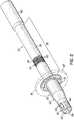
- Still another embodiment of the present inventionis directed to a malleable member 128 for use with a cannula 130 and is shown in FIG. 7 .
- the malleable member 182includes a plurality of transverse struts 132 with distal and proximal struts 134, 136 that are similar to those of the malleable member 94 of FIG. 2 .
- the illustrative malleable member 128includes a segmented strut 138 that extends in a direction that is parallel to the lengthwise central axis of the cannula 130.
- the segmented strut 138is discontinuous in that each successive segment 138a, 138b, 138c, 138d is circumferentially displaced about the transverse struts 132 relative to an adjacent segment 138a, 138b, 138c, 138d.
- the segments 138a, 138b, 138c, 138dare, therefore, spaced in at least two circumferential positions along the malleable member 128, which may be, but is not limited to, 180 degrees apart. If three circumferential positions are used, then adjacent segments may have circumferential positions that are spaced about 120 degrees apart. Generally, the circumferential spacing of adjacent segments may be determined by dividing 360 degrees by the number of segment positions desired. In the illustrative embodiment of FIG. 7 , four segment positions are used and would be preferentially spaced by about 90 degrees. However, one of ordinary skill in the art would readily appreciate that the spacing of segments need not be uniform or limited by the method of determination described herein.
Landscapes
- Health & Medical Sciences (AREA)
- Heart & Thoracic Surgery (AREA)
- Engineering & Computer Science (AREA)
- Cardiology (AREA)
- Biomedical Technology (AREA)
- Anesthesiology (AREA)
- Mechanical Engineering (AREA)
- Hematology (AREA)
- Life Sciences & Earth Sciences (AREA)
- Animal Behavior & Ethology (AREA)
- General Health & Medical Sciences (AREA)
- Public Health (AREA)
- Veterinary Medicine (AREA)
- External Artificial Organs (AREA)
Description
- The present disclosure relates generally to medical devices for assisting in the conduction of bodily fluids and, more particularly, to cannulae for use in moving bodily fluids.
- Various devices and methods have been utilized to assist in conducting bodily fluids. Blood pumps with inflow and outflow cannulae assist the heart in circulating blood in a patient experiencing congestive heart failure, for example, when a transplant organ is not available or the patient is not a suitable candidate for transplant. The blood pump may be fluidically attached to the heart and/or other vascular structure by the cannulae and then located remotely within the patient or left to remain external to the patient.
- The conventional cannula design for these procedures is a molded polymeric structure that may include a reinforcement structure, for example, a metallic or polymeric braid or coil, for reducing the likelihood of kink formation. While this solution has been effective for its intended purpose, the reinforcement structure limits the ability of the physician to customize the shape of the cannula to a particular patient's anatomy.
- In addition to the reinforcement structure, some cannulae include a malleable device, such as a tube or rod, extending the length of the cannula for retaining a shape of the cannula. However, some of these known, conventional malleable devices require assembly by the physician or may move relative to the reinforcement structure. As a result, the shape of the cannula may inadvertently be altered and/or the cannula material may become damaged. Therefore, there remains a need for a cannula design that addresses one or more of these issues.
US 5329923 discloses a torquable tubular member for use in a flexible elongate device comprising an elongate tubular body having a cylindrical wall and a longitudinal axis extending longitudinally of the cylindrical wall. The cylindrical wall has formed therein a plurality of spaced-apart slots spaced longitudinally of the longitudinal axis.WO 2005/094525 A2 relates to an apparatus and method for connecting a conduit to a hollow organ.US 2002/0183584 A1 relates to an apparatus for surgically implantable pumps that provides a mechanical device for augmenting or replacing the blood pumping action of damaged or diseased hearts.US 6001056 relates to ventricular assist devices.- In accordance with the present invention, there is provided a malleable cannula as defined in
claim 1. - In addition, further advantageous embodiments follow from the dependent claims.
FIG, 1 is a schematic representation of chest anatomy and illustrates a cardiac assist system having an inflow cannula extending between the heart and a pump, the cannula being constructed in accordance with one embodiment of the present invention.FIG. 2 is a perspective view of the cannula ofFIG. 1 with a portion of a jacket removed to illustrate a malleable member constructed in accordance with one embodiment of the present invention.FIG. 3 is a cross-sectional view of the cannula ofFIG. 1 .FIG, 4 is a side-elevational view of the malleable member ofFIG. 2 , shown in a straight configuration, with the cannula environment shown in phantom.FIG, 4A is a side-elevational view of the malleable member bent in an upwardly-oriented direction, with the cannula environment shown in phantom.FIG, 4B is a side-elevational view of the malleable member bent in a downwardly oriented direction, with the cannula environment shown in phantom.FIG. 5A is a top view of the malleable member ofFIG. 3 , shown in a straight configuration.FIG. 5B is a top view of the malleable member ofFIG. 3 bent in a lateral serpentine configuration, with the cannula environment shown in phantom.FIG. 6 is a side-elevational view of a malleable member in accordance with another illustrative example, with the cannula environment shown in phantom.FIG. 7 is a side-elevational view of a malleable member in accordance with yet another embodiment of the present invention, with the cannula environment shown in phantom.- While the various embodiments of the present invention may be useful for procedures involving any organ or cavity within the body, including, for example, the kidneys, the bladder, the stomach, or the heart, the particular embodiments of the present invention illustrated herein are drawn specifically to applications with the heart.
- References to "embodiments" throughout the description which are not under the scope of the appended claims merely represent possible exemplary executions and are therefore not part of the present invention.
- The invention is defined by the appended claims.
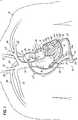
FIG. 1 illustrates acirculatory assist device 10 implanted in a patient 14. For illustrative purposes, certain anatomy is shown, including, theheart 12 of the patient 14 having a right atrium 16, aleft atrium 18, aright ventricle 20, and aleft ventricle 22. Blood from the left and rightsubclavian veins jugular veins superior vena cava 32 while blood from the lower parts of the body enters the right atrium 16 through theinferior vena cava 34. The blood is pumped from the right atrium 16, to theright ventricle 20, and to the lungs (not shown) to be oxygenated. Blood returning from the lungs enters theleft atrium 18 via thepulmonary veins 36 and is pumped into theleft ventricle 22. Blood leaving theleft ventricle 22 enters theaorta 38 and flows into the leftsubclavian artery 40, the leftcommon carotid 42, and thebrachiocephalic trunk 44, including the rightsubclavian artery 46 and the rightcommon carotid 48.- With respect to the implanted
circulatory assist device 10, twocannulae 50, 52 (inflow and outflow, respectively) extend between cardiovascular structures and apump 54. Thepump 54 may be any implantable or extracorporeal pump that is radially- and/or axially-driven. Those skilled in this art, however, recognize that other types of pumps may be used in other embodiments and may include pumps such as those described inU.S. Application Serial No. 11/627,444 , entitled HEART ASSIST SYSTEM and published asU.S. Application Publication No. 2007/0197854 . Still other pumps may include those that are commercially-available, such as the SYNERGY Pocket Micro-Pump from CircuLite Inc. (Saddle Brook, NJ). - A
cable 56 may extend transdermally from thepump 54 to a position in the abdomen where thecable 56 exits the patient 14 and connects to a power supply (not shown). Suitable power supplies may include a universal-type power supply that sends power to thepump 54 via thecable 56, such as a rechargeable battery pack. - The
inflow cannula 50 may include a distally-positionedtip 62 that is configured to extend through a wall of theheart 12 or, more specifically as shown inFIG. 1 , through theapex 64 and into theleft ventricle 22. Theoutflow cannula 52 may extend from anoutflow port 51 of thepump 54 to theaorta 38 and is secured with one ormore sutures 53. - Turning now to
FIG. 2 , additional details of theinflow cannula 50 and thetip 62 are described with greater detail. While only theinflow cannula 50 is described in such detail, it would be understood that theoutflow cannula 52 may include similar construction and features as theinflow cannula 50 or would be otherwise constructed in a manner that is known to those of ordinary skill in the art. Thetip 62 may be constructed from a metallic material, such as titanium, a titanium alloy, stainless steel, or platinum having a sintered section or at least a portion covered by a fabric to promote and control the in-growth of tissue. Alternatively, thetip 62 may be molded from a thermoset material, such as silicone, or a thermoplastic material, such as polyurethane. An example of a polyurethane that may be used is CARBOTHANE (Lubrizol Advanced Materials, Inc., Cleveland, Ohio). If a relatively conformable design is desired, thetip 62 may be constructed from a material having a durometer ranging from about shore 25A to about shore 90A. If a relatively rigid design is desired, thetip 62 may be constructed from a material having a durometer ranging from about shore 55D to about shore 90D. - To minimize the chance of thrombus formation, an insert molding process may be used to eliminate parting lines on the
tip 62, i.e., those places where a mismatch of material may occur. Use of the insert molding process results in aluminal surface 66 that is smooth and seamless for direct contact with blood flowing through thetip 62. Accordingly, it may not be necessary to coat theluminal surface 66 of thetip 62 with an anti-thrombotic material. These coatings may, however, be included if so desired. - To increase hemocompatibility of metallic-constructions, the
tip 62 may be polished to minimize irregularities resulting from the machining process. The highly polished surface minimizes the proliferation of cells, hence minimizing the likelihood that tissue will grow over thetip 62 and occlude blood flow through thetip 62 and into theinflow cannula 50. Alternatively, or additionally, thetip 62 may include a tissue in-growth band 89 to limit and/or control cell growth relative to thetip 62. The tissue in-growth band 89 may be constructed from a porous polymeric material, such as expanded polytetrafluoroethylene ("ePTFE"), a woven polyester fabric tubing (e.g., DACRON brand of polyester fabric), velour, or other like material that creates a scaffolding to which cells adhere. - The
tip 62 may include certain structures and features that are configured to further reduce occlusion of thetip 62 and theinflow cannula 50. For example, inFIG. 3 , thetip 62 includes a distally-positionedcage 78 having a distally-positionedring 82 and a plurality ofopenings 84 extending proximally from thering 82. Theopenings 84 permit blood to be continuously withdrawn from the left ventricle 22 (FIG. 1 ) into thetip 62, even when adistal tip end 86 of thecage 78 becomes obstructed or occluded, such as by the mitral valve chordae 89 (FIG. 1 ) or adjacent wall tissue of theheart 12. Thetip 62 may also include one or more barbs 90 configured to couple and retain theinflow cannula 50 to thetip 62. Accordingly, the distal end of theinflow cannula 50 should be sufficiently flexible so as to slide over the barbs 90 of thetip 62. - Referring still to
FIGS. 1 and2 , thetip 62, as shown, is secured to the apex 64 of theheart 12. Suitable methods for securing thetip 62 may include, for example, one or more purse string sutures, one or more deployable anchors (such as those described inU.S. Application Serial No. 12/256,911 , entitled TRANSSEPTAL CANNULA, TIP, DELIVERY SYSTEM, AND METHOD and published asU.S. Application Publication No. 2009/0112050 ), a cannula securement device (such as those described inU.S. Application Serial No. 12/917,525 , entitled CANNULA STABILIZER and published asU.S. Application Publication No. 2011/0118668 ), or, as shown, with an attachment ring 68 (FIG. 1 ). In some embodiments of the present invention, theattachment ring 68 may be similar to the devices described inU.S. Application Serial No. 61/531,957 - With reference to
FIGS. 3 and 4 , theinflow cannula 50 and theattachment ring 68 are shown and described in greater detail. The illustratedattachment ring 68 includes arigid portion 72 and a tissue in-growth band 74 that is coupled to therigid portion 72. Therigid portion 72, with the tissue in-growth band 74, includes a lumen (not shown) that is configured to receive thetip 62 as described in detail below. - The tissue in-
growth band 74 may be constructed from a material that is similar to those described previously with respect to the tissue in-growth band 89 of thetip 62. Therigid portion 72 is configured to be sutured through the tissue in-growth band 89 to an outer surface of the apex 64. Thetip 62 of theinflow cannula 50 is inserted through theattachment ring 68 and the muscle comprising the wall of the apex 64 and into theleft ventricle 22. - Referring still to
FIGS. 3 and 4 , theinflow cannula 50, itself, may be constructed in a manner similar to any suitable intravascular cannula device. This may include, for example, a liner portion 92 constructed from materials such as an extruded aliphatic, polycarbonate-base polyurethane, aliphatic polyether polyurethane, aromatic polyether polyurethane, aromatic polycarbonate-based polyurethane, silicone-modified polyurethane, or silicone. Antimicrobial agents may be embedded within the material prior to the forming process to effectively reduce or eliminate the presence of bio-film and reduce the potential for infection. Alternatively, the antimicrobial agent may be applied after the molding process is complete. However, the liner 92 is not required. - A
malleable member 94, according to one embodiment of the present invention, surrounds the liner 92 and may be encased between the liner 92 and ajacket 96 constructed from polymeric materials similar to the listing of materials for the liner 92. Themalleable member 94 is configured to provide theinflow cannula 50 with a degree of plasticity allowing the physician to bend and shape theinflow cannula 50 to fit the patient's anatomy without breakage. While not required, themalleable member 94 may be positioned along amedial portion 110 of theinflow cannula 50 so that the proximal and distal ends of theinflow cannula 50 remain sufficiently flexible for coupling to the pump 54 (FIG. 1 ) and thetip 62, respectively. - With the
malleable member 94, theinflow cannula 50 is configured to retain the desired shape without relaxing into an unformed and loose shape. In that regard, and as shown in the illustrative embodiment, themalleable member 94 includes a strut 98 (for example, a longitudinal strut 98) that extends the length of themalleable member 94 and is generally parallel to a lengthwise central axis of thecannula 50. A plurality oftransverse struts 100, illustrated as successive rings, extends laterally away from thelongitudinal strut 98. Said another way, thelongitudinal strut 98 extends along a longitudinal lengthwise direction of themalleable member 94 and may form a unitary structure with, and is tangential to, the plurality of transverse struts 100. Proximal anddistal struts transverse struts 100 and may also be formed as a unitary structure with thelongitudinal strut 98 and/or the plurality of transverse struts 100. The proximal anddistal struts malleable member 94 within thejacket 96. - In some embodiments, the plurality of
transverse struts 100 may have a constant pitch, e.g., a number of struts per unit of longitudinal distance; however, in other embodiments, the pitch may vary along the longitudinal length of theinflow cannula 50 so as to vary a malleableness of thecannula 50. For example, and in accordance with one embodiment of the present invention, themalleable member 94 may be constructed with a first portion having struts spaced at a first pitch and a second portion having struts spaced at a second pitch, the first pitch being greater than the second pitch. The resultant cannula would exhibit less shape control in the first portion as compared to the second portion. - The
malleable member 94, being configured to assume and retain the desired shape without fracturing, may be constructed from any suitably malleable material, that is, a material that is generally bendable, formable, or pliable without fracture or breakage. Exemplary materials may include, for example, annealed steel, MP35N, or other metallic materials. If radiopacity is desired forin vivo visualization under fluoroscopy or echocardiogram, the malleable material may be comprised of a highly dense material, such as tantalum or gold, or incorporate radiopaque materials therein. In still other embodiments of the present invention, themalleable member 94 may be constructed from metallic tubing, such as a hypotube, that is laser or otherwise cut to the desired configuration. - The
inflow cannula 50, having themalleable member 94 as described above, may be positioned, and will retain, various configurations. As shown inFIGS. 4A-5B , theinflow cannula 50 may be placed in a straight configuration, for example, such as would be the packaged configuration during shipment and before a surgical use. As necessary or desired, the physician may manipulate theinflow cannula 50 from the straight configuration to a bent configuration in which at least one portion of theinflow cannula 50 is deflected in at least one direction away from the longitudinal lengthwise axis of thecannula 50. - The configurability of the
inflow cannula 50, however, may be limited. For example,FIGS. 4A and 4B illustrate the relative range of motion of themalleable member 94 in an upwardly-directed bend (FIG. 4A ) and in a downwardly-directed bend (FIG. 4B ). More specifically, the illustrativemalleable member 94 inherently provides a greater range of motion in the upwardly-directed bend as compared with the downwardly-directed bend. As theinflow cannula 50 is bent downwardly, as shown inFIG. 4B , the angle of deflection is limited by the relative spacing of the plurality of transverse struts 100. Accordingly, the amount of deflection may be limited by the distance separating adjacent ones of the plurality of transverse struts 100 (e.g., the pitch) as well as the thickness of each of the plurality of transverse struts 100. FIG. 5B illustrates a similar limitation in the range of motion for theinflow cannula 50. However, the movement of theinflow cannula 50 shown inFIG. 5B is in a lateral, serpentine direction, as indicated byarrows 105, and not along an axial direction shown inFIGS. 4A and 4B .- Returning again to
FIGS. 2 and3 , additional features of themalleable member 94 and theinflow cannula 50 are shown and described in detail. In this particular embodiment of the present invention, theinflow cannula 50 includes aproximal hub 106 configured to be coupled to an inflow port 108 (FIG. 1 ) of the pump 54 (FIG. 1 ). Accordingly, the material comprising theproximal hub 106 of theinflow cannula 50, whether the material is the liner 92, thejacket 96, or both, may be thickened to provide an outer diameter at thehub 106 that is larger than the outer diameter of the remaining portion (for instance, the medial portion 110) of theinflow cannula 50. Thehub 106 should be sufficiently flexible so that physician may slide thehub 106 onto the receiving inflow port 108 (FIG. 1 ) of the pump 54 (FIG. 1 ). - In use, and with reference to
FIG. 1 , the physician may bend or otherwise shape theinflow cannula 50 before, during, or after thetip 62 is coupled or otherwise secured to the apex 64 of theheart 12. The shape may depend, at least in part, on the anatomy of the particular patient 14 and the position selected for thepump 54. InFIG. 1 , theinflow cannula 50 is configured into an "L" shape such that thetip 62 aligns, generally perpendicularly, with the apex 64 and theleft ventricle 22 while theproximal hub 1 06 is aligned, generally collinearly, with theinflow 108 of thepump 54 within the abdominal cavity of the patient 14. While not illustrated herein, without the malleable member 94 (FIG. 2 ), theinflow cannula 50 would otherwise relax into an unconstrained and loose shape in which themedial portion 110 falls, or dangles, below theinflow 108 of thepump 54. With themalleable member 94, theinflow cannula 50 retains the designated shape until and unless the physician further manipulates or otherwise bends theinflow cannula 50. - In accordance with another illustrative example, and with reference to
FIG. 6 , amalleable member 114 for use in acannula 116 may include astrut 118 positioned parallel to the lengthwise central axis of thecannula 116. Proximal anddistal struts strut 118 in a manner that is similar to themalleable member 94 ofFIG. 2 . However, inFIG. 6 , themalleable member 114 further includes a continuous,helical strut 124 that is coupled to thestrut 118 tangentially along one side of thehelical strut 124. Thehelical strut 124 may be constructed, for example, as a coil. Although not required, thehelical strut 124 may terminate proximally and distally with the proximal anddistal struts distal struts helical strut 124 and then welded or otherwise secured thereto. The proximal, distal, and/orhelical struts longitudinal strut 118, if desired, to reduce movement of thestruts - The
helical strut 124 ofFIG. 6 enables greater range of motion and configuration of thecannula 116 as compared to theinflow cannula 50 ofFIG. 4A . The increased motion, or greater degree of deflection, may be due, at least one part, to the coil-like configuration of thehelical strut 118 in which the likelihood that adjacent ones of thestruts 118 will make contact is reduced. - Still another embodiment of the present invention is directed to a malleable member 128 for use with a
cannula 130 and is shown inFIG. 7 . The malleable member 182 includes a plurality oftransverse struts 132 with distal andproximal struts malleable member 94 ofFIG. 2 . However, the illustrative malleable member 128 includes asegmented strut 138 that extends in a direction that is parallel to the lengthwise central axis of thecannula 130. More particularly, thesegmented strut 138 is discontinuous in that eachsuccessive segment adjacent segment segments FIG. 7 , four segment positions are used and would be preferentially spaced by about 90 degrees. However, one of ordinary skill in the art would readily appreciate that the spacing of segments need not be uniform or limited by the method of determination described herein. - Similar to the
malleable member 114 ofFIG. 6 , the malleable member 128 is sufficiently malleable to permit a wide range of motion and deflection without limiting motion a particular direction. Yet, thecannula 130 is sufficiently stable to retain the formed shape designated by the physician. - While the present invention has been illustrated by a description of various illustrative embodiments and while these embodiments have been described in some detail, additional advantages and modifications will readily appear to those skilled in the art. The various features of the invention may be used alone or in any combination depending on the needs and preferences of the user. The invention is defined by the appended claims.
Claims (11)
- A malleable cannula (50, 52, 130) comprising:a jacket (96); anda malleable member (94, 128) surrounded by the jacket, the malleable member having a proximal end, a distal end, and a lumen extending therebetween and along a lengthwise axis of the malleable cannula,a liner (92) coupled to an inner surface of the lumen of the malleable member,the malleable member including a longitudinal strut (138) extending parallel to the lengthwise axis and a plurality of transverse struts (100, 132) coupled to and extending laterally from the longitudinal strut and around at least a portion of the lumen of the liner, wherein the longitudinal strut is discontinuous along a longitudinal length of the malleable member and is comprised of a plurality of segments, each of the plurality of segments being circumferentially displaced from an adjacent one of the plurality of segments and about the plurality of transverse struts,the malleable member being configured to assume and maintain a formed shape of the malleable cannula.
- The malleable cannula of claim 1, wherein the malleable member further comprises:a proximal strut (102, 134) coupled to and extending laterally from the longitudinal strut at a proximal end of the malleable member, the proximal strut extending at least partially around the lumen; anda distal strut (104, 136) coupled to and extending laterally from the longitudinal strut at a distal end of the malleable member, the distal strut extending at least partially around the lumen,wherein the proximal and distal struts have a width dimension that is greater than a width dimension of the traverse struts of the plurality to further anchor the malleable member within the jacket.
- The malleable cannula of claim 2, wherein the proximal strut, the distal strut, and the plurality of transverse struts are constructed as a unitary structure.
- The malleable cannula of claim 3, wherein the unitary structure further includes the longitudinal strut.
- The malleable cannula of claim 1, wherein the malleable member is constructed from a metallic tube.
- The malleable cannula of claim 1, wherein the malleable member is constructed from annealed steel, MP35N, tantalum, gold, or a combination thereof.
- The malleable cannula of claim 1, wherein the plurality of transverse struts includes a spring, a helix, or a plurality of successive rings.
- The malleable cannula of claim 1, wherein the transverse struts of the plurality are spaced apart by a pitch.
- The malleable cannula of claim 1, further comprising:
a tip (60) coupled to a distal end of the malleable cannula and configured to extend through a biological tissue. - The malleable cannula of claim 1, wherein each of the plurality of segments is located at one of a number of circumferential positions about the plurality of struts, the number of circumferential positions being greater than 1.
- The malleable cannula of claim 10, wherein a select one of the plurality of segments is circumferentially displaced from an adjacent one of the plurality of segments by 360 degrees divided by the number of circumferential positions about the plurality of transverse struts.
Applications Claiming Priority (2)
| Application Number | Priority Date | Filing Date | Title |
|---|---|---|---|
| US13/788,039US10688230B2 (en) | 2013-03-07 | 2013-03-07 | Malleable cannula |
| PCT/US2014/013709WO2014137511A1 (en) | 2013-03-07 | 2014-01-30 | Malleable cannula |
Publications (2)
| Publication Number | Publication Date |
|---|---|
| EP2964303A1 EP2964303A1 (en) | 2016-01-13 |
| EP2964303B1true EP2964303B1 (en) | 2019-11-27 |
Family
ID=50071826
Family Applications (1)
| Application Number | Title | Priority Date | Filing Date |
|---|---|---|---|
| EP14703752.7AActiveEP2964303B1 (en) | 2013-03-07 | 2014-01-30 | Malleable cannula |
Country Status (3)
| Country | Link |
|---|---|
| US (1) | US10688230B2 (en) |
| EP (1) | EP2964303B1 (en) |
| WO (1) | WO2014137511A1 (en) |
Families Citing this family (31)
| Publication number | Priority date | Publication date | Assignee | Title |
|---|---|---|---|---|
| US10779855B2 (en) | 2011-08-05 | 2020-09-22 | Route 92 Medical, Inc. | Methods and systems for treatment of acute ischemic stroke |
| EP4101399B1 (en) | 2011-08-05 | 2025-04-09 | Route 92 Medical, Inc. | System for treatment of acute ischemic stroke |
| US10449274B2 (en)* | 2013-06-26 | 2019-10-22 | Circulite, Inc. | System and method of facilitating connection between cannulae and a blood pump |
| US9265512B2 (en) | 2013-12-23 | 2016-02-23 | Silk Road Medical, Inc. | Transcarotid neurovascular catheter |
| US9241699B1 (en) | 2014-09-04 | 2016-01-26 | Silk Road Medical, Inc. | Methods and devices for transcarotid access |
| EP3145558B1 (en) | 2014-05-20 | 2021-12-15 | CircuLite, Inc. | Heart assist systems and methods |
| US10265086B2 (en) | 2014-06-30 | 2019-04-23 | Neuravi Limited | System for removing a clot from a blood vessel |
| US11027104B2 (en) | 2014-09-04 | 2021-06-08 | Silk Road Medical, Inc. | Methods and devices for transcarotid access |
| CN119949953A (en) | 2015-02-04 | 2025-05-09 | 92号医疗公司 | Intravascular access system, dilator and system including dilator |
| US10426497B2 (en) | 2015-07-24 | 2019-10-01 | Route 92 Medical, Inc. | Anchoring delivery system and methods |
| US11065019B1 (en) | 2015-02-04 | 2021-07-20 | Route 92 Medical, Inc. | Aspiration catheter systems and methods of use |
| US9717830B2 (en) | 2015-10-28 | 2017-08-01 | Circulite, Inc. | Inflow cannula and blood flow assist system |
| EP3311860A1 (en)* | 2016-10-20 | 2018-04-25 | Berlin Heart GmbH | Cannula, cannula system, heart pump system and method for volume discharge of a heart |
| EP3528864B1 (en)* | 2016-10-20 | 2020-12-30 | Heartware, Inc. | Inflow cannula |
| CN110392591B (en) | 2017-01-10 | 2022-06-03 | 92号医疗公司 | Aspiration catheter system and method of use |
| US10864350B2 (en) | 2017-01-20 | 2020-12-15 | Route 92 Medical, Inc. | Single operator intracranial medical device delivery systems and methods of use |
| CA3068628A1 (en)* | 2017-06-30 | 2019-01-03 | Reliantheart, Inc. | Vascular graft protector |
| EP3485926A1 (en)* | 2017-11-16 | 2019-05-22 | Berlin Heart GmbH | Inlet cannula for a fluid pump |
| JP7616642B2 (en) | 2018-05-17 | 2025-01-17 | ルート92メディカル・インコーポレイテッド | Suction catheter system and method of use |
| ES2910600T3 (en) | 2019-03-04 | 2022-05-12 | Neuravi Ltd | Powered Clot Recovery Catheter |
| EP3791815B1 (en) | 2019-09-11 | 2024-06-26 | Neuravi Limited | Expandable mouth catheter |
| US11779364B2 (en) | 2019-11-27 | 2023-10-10 | Neuravi Limited | Actuated expandable mouth thrombectomy catheter |
| US11839725B2 (en) | 2019-11-27 | 2023-12-12 | Neuravi Limited | Clot retrieval device with outer sheath and inner catheter |
| US11944327B2 (en) | 2020-03-05 | 2024-04-02 | Neuravi Limited | Expandable mouth aspirating clot retrieval catheter |
| US11883043B2 (en) | 2020-03-31 | 2024-01-30 | DePuy Synthes Products, Inc. | Catheter funnel extension |
| US11759217B2 (en) | 2020-04-07 | 2023-09-19 | Neuravi Limited | Catheter tubular support |
| US20210393277A1 (en)* | 2020-06-18 | 2021-12-23 | Neuravi Limited | Catheter mouth designs |
| WO2022076893A1 (en) | 2020-10-09 | 2022-04-14 | Route 92 Medical, Inc. | Aspiration catheter systems and methods of use |
| US11872354B2 (en) | 2021-02-24 | 2024-01-16 | Neuravi Limited | Flexible catheter shaft frame with seam |
| US11937839B2 (en) | 2021-09-28 | 2024-03-26 | Neuravi Limited | Catheter with electrically actuated expandable mouth |
| US12011186B2 (en) | 2021-10-28 | 2024-06-18 | Neuravi Limited | Bevel tip expandable mouth catheter with reinforcing ring |
Citations (3)
| Publication number | Priority date | Publication date | Assignee | Title |
|---|---|---|---|---|
| US6001056A (en)* | 1998-11-13 | 1999-12-14 | Baxter International Inc. | Smooth ventricular assist device conduit |
| US20020183584A1 (en)* | 2001-06-05 | 2002-12-05 | Shannon Donald T. | Non-porous smooth ventricular assist device conduit |
| WO2005094525A2 (en)* | 2004-03-23 | 2005-10-13 | Correx, Inc. | Apparatus and method for connecting a conduit to a hollow organ |
Family Cites Families (14)
| Publication number | Priority date | Publication date | Assignee | Title |
|---|---|---|---|---|
| US4639252A (en) | 1985-04-05 | 1987-01-27 | Research Medical, Inc. | Venous return catheter |
| US4976688A (en) | 1989-02-03 | 1990-12-11 | Rosenblum Jeffrey L | Position-adjustable thoracic catheter |
| US5454787A (en) | 1991-02-15 | 1995-10-03 | Lundquist; Ingemar H. | Torquable tubular assembly and torquable catheter utilizing the same |
| US5329923A (en) | 1991-02-15 | 1994-07-19 | Lundquist Ingemar H | Torquable catheter |
| US20030069522A1 (en)* | 1995-12-07 | 2003-04-10 | Jacobsen Stephen J. | Slotted medical device |
| US6016848A (en) | 1996-07-16 | 2000-01-25 | W. L. Gore & Associates, Inc. | Fluoropolymer tubes and methods of making same |
| US6123699A (en) | 1997-09-05 | 2000-09-26 | Cordis Webster, Inc. | Omni-directional steerable catheter |
| US6152911A (en) | 1998-08-27 | 2000-11-28 | Chase Medical, Inc. | Venous return catheter having multiple helical support members |
| US6022343A (en) | 1998-09-03 | 2000-02-08 | Intratherapeutics, Inc. | Bridged coil catheter support structure |
| US6544215B1 (en) | 1998-10-02 | 2003-04-08 | Scimed Life Systems, Inc. | Steerable device for introducing diagnostic and therapeutic apparatus into the body |
| US6976979B2 (en) | 2002-10-31 | 2005-12-20 | Medtronic, Inc. | Malleable cannula |
| DE602004010276D1 (en) | 2004-11-10 | 2008-01-03 | Creganna Technologies Ltd | Introducer catheter assembly for stents |
| US20100036364A1 (en)* | 2008-08-06 | 2010-02-11 | C. R. Bard, Inc. | Catheter Introducer |
| JP5685256B2 (en) | 2009-09-21 | 2015-03-18 | メドトロニック,インコーポレイテッド | Stented transcatheter prosthetic heart valve delivery system and method |
- 2013
- 2013-03-07USUS13/788,039patent/US10688230B2/ennot_activeExpired - Fee Related
- 2014
- 2014-01-30WOPCT/US2014/013709patent/WO2014137511A1/enactiveApplication Filing
- 2014-01-30EPEP14703752.7Apatent/EP2964303B1/enactiveActive
Patent Citations (3)
| Publication number | Priority date | Publication date | Assignee | Title |
|---|---|---|---|---|
| US6001056A (en)* | 1998-11-13 | 1999-12-14 | Baxter International Inc. | Smooth ventricular assist device conduit |
| US20020183584A1 (en)* | 2001-06-05 | 2002-12-05 | Shannon Donald T. | Non-porous smooth ventricular assist device conduit |
| WO2005094525A2 (en)* | 2004-03-23 | 2005-10-13 | Correx, Inc. | Apparatus and method for connecting a conduit to a hollow organ |
Also Published As
| Publication number | Publication date |
|---|---|
| US20140257018A1 (en) | 2014-09-11 |
| EP2964303A1 (en) | 2016-01-13 |
| US10688230B2 (en) | 2020-06-23 |
| WO2014137511A1 (en) | 2014-09-12 |
Similar Documents
| Publication | Publication Date | Title |
|---|---|---|
| EP2964303B1 (en) | Malleable cannula | |
| US11918725B2 (en) | Dual lumen cannula | |
| US11660441B2 (en) | Catheter pump | |
| US9132216B2 (en) | Devices, methods and systems for establishing supplemental blood flow in the circulatory system | |
| CN102665785A (en) | Heart failure treatment methods and devices | |
| KR20150126877A (en) | Transseptal cannula, tip, delivery system, and method | |
| EP2498859B1 (en) | Cannula stabilizer | |
| EP3185923B1 (en) | Malleable cannula | |
| HK1174291A (en) | Methods and devices for treating heart failure |
Legal Events
| Date | Code | Title | Description |
|---|---|---|---|
| PUAI | Public reference made under article 153(3) epc to a published international application that has entered the european phase | Free format text:ORIGINAL CODE: 0009012 | |
| 17P | Request for examination filed | Effective date:20150923 | |
| AK | Designated contracting states | Kind code of ref document:A1 Designated state(s):AL AT BE BG CH CY CZ DE DK EE ES FI FR GB GR HR HU IE IS IT LI LT LU LV MC MK MT NL NO PL PT RO RS SE SI SK SM TR | |
| AX | Request for extension of the european patent | Extension state:BA ME | |
| RIN1 | Information on inventor provided before grant (corrected) | Inventor name:FARNAN, ROBERT, C. | |
| DAX | Request for extension of the european patent (deleted) | ||
| STAA | Information on the status of an ep patent application or granted ep patent | Free format text:STATUS: EXAMINATION IS IN PROGRESS | |
| 17Q | First examination report despatched | Effective date:20181115 | |
| REG | Reference to a national code | Ref country code:DE Ref legal event code:R079 Ref document number:602014057424 Country of ref document:DE Free format text:PREVIOUS MAIN CLASS: A61M0025000000 Ipc:A61M0001100000 | |
| RIC1 | Information provided on ipc code assigned before grant | Ipc:A61M 1/12 20060101ALI20190627BHEP Ipc:A61M 1/10 20060101AFI20190627BHEP | |
| GRAP | Despatch of communication of intention to grant a patent | Free format text:ORIGINAL CODE: EPIDOSNIGR1 | |
| STAA | Information on the status of an ep patent application or granted ep patent | Free format text:STATUS: GRANT OF PATENT IS INTENDED | |
| INTG | Intention to grant announced | Effective date:20190822 | |
| GRAS | Grant fee paid | Free format text:ORIGINAL CODE: EPIDOSNIGR3 | |
| GRAA | (expected) grant | Free format text:ORIGINAL CODE: 0009210 | |
| STAA | Information on the status of an ep patent application or granted ep patent | Free format text:STATUS: THE PATENT HAS BEEN GRANTED | |
| AK | Designated contracting states | Kind code of ref document:B1 Designated state(s):AL AT BE BG CH CY CZ DE DK EE ES FI FR GB GR HR HU IE IS IT LI LT LU LV MC MK MT NL NO PL PT RO RS SE SI SK SM TR | |
| REG | Reference to a national code | Ref country code:GB Ref legal event code:FG4D | |
| REG | Reference to a national code | Ref country code:CH Ref legal event code:EP | |
| REG | Reference to a national code | Ref country code:AT Ref legal event code:REF Ref document number:1205994 Country of ref document:AT Kind code of ref document:T Effective date:20191215 | |
| REG | Reference to a national code | Ref country code:DE Ref legal event code:R096 Ref document number:602014057424 Country of ref document:DE | |
| REG | Reference to a national code | Ref country code:IE Ref legal event code:FG4D | |
| REG | Reference to a national code | Ref country code:NL Ref legal event code:MP Effective date:20191127 | |
| REG | Reference to a national code | Ref country code:LT Ref legal event code:MG4D | |
| PG25 | Lapsed in a contracting state [announced via postgrant information from national office to epo] | Ref country code:LV Free format text:LAPSE BECAUSE OF FAILURE TO SUBMIT A TRANSLATION OF THE DESCRIPTION OR TO PAY THE FEE WITHIN THE PRESCRIBED TIME-LIMIT Effective date:20191127 Ref country code:SE Free format text:LAPSE BECAUSE OF FAILURE TO SUBMIT A TRANSLATION OF THE DESCRIPTION OR TO PAY THE FEE WITHIN THE PRESCRIBED TIME-LIMIT Effective date:20191127 Ref country code:BG Free format text:LAPSE BECAUSE OF FAILURE TO SUBMIT A TRANSLATION OF THE DESCRIPTION OR TO PAY THE FEE WITHIN THE PRESCRIBED TIME-LIMIT Effective date:20200227 Ref country code:FI Free format text:LAPSE BECAUSE OF FAILURE TO SUBMIT A TRANSLATION OF THE DESCRIPTION OR TO PAY THE FEE WITHIN THE PRESCRIBED TIME-LIMIT Effective date:20191127 Ref country code:GR Free format text:LAPSE BECAUSE OF FAILURE TO SUBMIT A TRANSLATION OF THE DESCRIPTION OR TO PAY THE FEE WITHIN THE PRESCRIBED TIME-LIMIT Effective date:20200228 Ref country code:NO Free format text:LAPSE BECAUSE OF FAILURE TO SUBMIT A TRANSLATION OF THE DESCRIPTION OR TO PAY THE FEE WITHIN THE PRESCRIBED TIME-LIMIT Effective date:20200227 Ref country code:LT Free format text:LAPSE BECAUSE OF FAILURE TO SUBMIT A TRANSLATION OF THE DESCRIPTION OR TO PAY THE FEE WITHIN THE PRESCRIBED TIME-LIMIT Effective date:20191127 Ref country code:NL Free format text:LAPSE BECAUSE OF FAILURE TO SUBMIT A TRANSLATION OF THE DESCRIPTION OR TO PAY THE FEE WITHIN THE PRESCRIBED TIME-LIMIT Effective date:20191127 | |
| PG25 | Lapsed in a contracting state [announced via postgrant information from national office to epo] | Ref country code:HR Free format text:LAPSE BECAUSE OF FAILURE TO SUBMIT A TRANSLATION OF THE DESCRIPTION OR TO PAY THE FEE WITHIN THE PRESCRIBED TIME-LIMIT Effective date:20191127 Ref country code:IS Free format text:LAPSE BECAUSE OF FAILURE TO SUBMIT A TRANSLATION OF THE DESCRIPTION OR TO PAY THE FEE WITHIN THE PRESCRIBED TIME-LIMIT Effective date:20200327 Ref country code:RS Free format text:LAPSE BECAUSE OF FAILURE TO SUBMIT A TRANSLATION OF THE DESCRIPTION OR TO PAY THE FEE WITHIN THE PRESCRIBED TIME-LIMIT Effective date:20191127 | |
| PG25 | Lapsed in a contracting state [announced via postgrant information from national office to epo] | Ref country code:AL Free format text:LAPSE BECAUSE OF FAILURE TO SUBMIT A TRANSLATION OF THE DESCRIPTION OR TO PAY THE FEE WITHIN THE PRESCRIBED TIME-LIMIT Effective date:20191127 | |
| PG25 | Lapsed in a contracting state [announced via postgrant information from national office to epo] | Ref country code:RO Free format text:LAPSE BECAUSE OF FAILURE TO SUBMIT A TRANSLATION OF THE DESCRIPTION OR TO PAY THE FEE WITHIN THE PRESCRIBED TIME-LIMIT Effective date:20191127 Ref country code:EE Free format text:LAPSE BECAUSE OF FAILURE TO SUBMIT A TRANSLATION OF THE DESCRIPTION OR TO PAY THE FEE WITHIN THE PRESCRIBED TIME-LIMIT Effective date:20191127 Ref country code:PT Free format text:LAPSE BECAUSE OF FAILURE TO SUBMIT A TRANSLATION OF THE DESCRIPTION OR TO PAY THE FEE WITHIN THE PRESCRIBED TIME-LIMIT Effective date:20200419 Ref country code:CZ Free format text:LAPSE BECAUSE OF FAILURE TO SUBMIT A TRANSLATION OF THE DESCRIPTION OR TO PAY THE FEE WITHIN THE PRESCRIBED TIME-LIMIT Effective date:20191127 Ref country code:ES Free format text:LAPSE BECAUSE OF FAILURE TO SUBMIT A TRANSLATION OF THE DESCRIPTION OR TO PAY THE FEE WITHIN THE PRESCRIBED TIME-LIMIT Effective date:20191127 Ref country code:DK Free format text:LAPSE BECAUSE OF FAILURE TO SUBMIT A TRANSLATION OF THE DESCRIPTION OR TO PAY THE FEE WITHIN THE PRESCRIBED TIME-LIMIT Effective date:20191127 | |
| REG | Reference to a national code | Ref country code:DE Ref legal event code:R097 Ref document number:602014057424 Country of ref document:DE | |
| PG25 | Lapsed in a contracting state [announced via postgrant information from national office to epo] | Ref country code:SM Free format text:LAPSE BECAUSE OF FAILURE TO SUBMIT A TRANSLATION OF THE DESCRIPTION OR TO PAY THE FEE WITHIN THE PRESCRIBED TIME-LIMIT Effective date:20191127 Ref country code:MC Free format text:LAPSE BECAUSE OF FAILURE TO SUBMIT A TRANSLATION OF THE DESCRIPTION OR TO PAY THE FEE WITHIN THE PRESCRIBED TIME-LIMIT Effective date:20191127 Ref country code:SK Free format text:LAPSE BECAUSE OF FAILURE TO SUBMIT A TRANSLATION OF THE DESCRIPTION OR TO PAY THE FEE WITHIN THE PRESCRIBED TIME-LIMIT Effective date:20191127 | |
| REG | Reference to a national code | Ref country code:CH Ref legal event code:PL | |
| REG | Reference to a national code | Ref country code:AT Ref legal event code:MK05 Ref document number:1205994 Country of ref document:AT Kind code of ref document:T Effective date:20191127 | |
| PLBE | No opposition filed within time limit | Free format text:ORIGINAL CODE: 0009261 | |
| STAA | Information on the status of an ep patent application or granted ep patent | Free format text:STATUS: NO OPPOSITION FILED WITHIN TIME LIMIT | |
| REG | Reference to a national code | Ref country code:BE Ref legal event code:MM Effective date:20200131 | |
| GBPC | Gb: european patent ceased through non-payment of renewal fee | Effective date:20200227 | |
| PG25 | Lapsed in a contracting state [announced via postgrant information from national office to epo] | Ref country code:LU Free format text:LAPSE BECAUSE OF NON-PAYMENT OF DUE FEES Effective date:20200130 | |
| 26N | No opposition filed | Effective date:20200828 | |
| REG | Reference to a national code | Ref country code:DE Ref legal event code:R079 Ref document number:602014057424 Country of ref document:DE Free format text:PREVIOUS MAIN CLASS: A61M0001100000 Ipc:A61M0060000000 | |
| PG25 | Lapsed in a contracting state [announced via postgrant information from national office to epo] | Ref country code:SI Free format text:LAPSE BECAUSE OF FAILURE TO SUBMIT A TRANSLATION OF THE DESCRIPTION OR TO PAY THE FEE WITHIN THE PRESCRIBED TIME-LIMIT Effective date:20191127 Ref country code:AT Free format text:LAPSE BECAUSE OF FAILURE TO SUBMIT A TRANSLATION OF THE DESCRIPTION OR TO PAY THE FEE WITHIN THE PRESCRIBED TIME-LIMIT Effective date:20191127 Ref country code:CH Free format text:LAPSE BECAUSE OF NON-PAYMENT OF DUE FEES Effective date:20200131 Ref country code:BE Free format text:LAPSE BECAUSE OF NON-PAYMENT OF DUE FEES Effective date:20200131 Ref country code:LI Free format text:LAPSE BECAUSE OF NON-PAYMENT OF DUE FEES Effective date:20200131 Ref country code:PL Free format text:LAPSE BECAUSE OF FAILURE TO SUBMIT A TRANSLATION OF THE DESCRIPTION OR TO PAY THE FEE WITHIN THE PRESCRIBED TIME-LIMIT Effective date:20191127 | |
| PG25 | Lapsed in a contracting state [announced via postgrant information from national office to epo] | Ref country code:IE Free format text:LAPSE BECAUSE OF NON-PAYMENT OF DUE FEES Effective date:20200130 Ref country code:GB Free format text:LAPSE BECAUSE OF NON-PAYMENT OF DUE FEES Effective date:20200227 Ref country code:IT Free format text:LAPSE BECAUSE OF FAILURE TO SUBMIT A TRANSLATION OF THE DESCRIPTION OR TO PAY THE FEE WITHIN THE PRESCRIBED TIME-LIMIT Effective date:20191127 | |
| PGFP | Annual fee paid to national office [announced via postgrant information from national office to epo] | Ref country code:FR Payment date:20201217 Year of fee payment:8 | |
| PGFP | Annual fee paid to national office [announced via postgrant information from national office to epo] | Ref country code:DE Payment date:20201217 Year of fee payment:8 | |
| PG25 | Lapsed in a contracting state [announced via postgrant information from national office to epo] | Ref country code:TR Free format text:LAPSE BECAUSE OF FAILURE TO SUBMIT A TRANSLATION OF THE DESCRIPTION OR TO PAY THE FEE WITHIN THE PRESCRIBED TIME-LIMIT Effective date:20191127 Ref country code:MT Free format text:LAPSE BECAUSE OF FAILURE TO SUBMIT A TRANSLATION OF THE DESCRIPTION OR TO PAY THE FEE WITHIN THE PRESCRIBED TIME-LIMIT Effective date:20191127 Ref country code:CY Free format text:LAPSE BECAUSE OF FAILURE TO SUBMIT A TRANSLATION OF THE DESCRIPTION OR TO PAY THE FEE WITHIN THE PRESCRIBED TIME-LIMIT Effective date:20191127 | |
| PG25 | Lapsed in a contracting state [announced via postgrant information from national office to epo] | Ref country code:MK Free format text:LAPSE BECAUSE OF FAILURE TO SUBMIT A TRANSLATION OF THE DESCRIPTION OR TO PAY THE FEE WITHIN THE PRESCRIBED TIME-LIMIT Effective date:20191127 | |
| REG | Reference to a national code | Ref country code:DE Ref legal event code:R119 Ref document number:602014057424 Country of ref document:DE | |
| PG25 | Lapsed in a contracting state [announced via postgrant information from national office to epo] | Ref country code:DE Free format text:LAPSE BECAUSE OF NON-PAYMENT OF DUE FEES Effective date:20220802 | |
| PG25 | Lapsed in a contracting state [announced via postgrant information from national office to epo] | Ref country code:FR Free format text:LAPSE BECAUSE OF NON-PAYMENT OF DUE FEES Effective date:20220131 |