EP2963838B1 - Method and apparatus for communication through power line - Google Patents
Method and apparatus for communication through power lineDownload PDFInfo
- Publication number
- EP2963838B1 EP2963838B1EP13876649.8AEP13876649AEP2963838B1EP 2963838 B1EP2963838 B1EP 2963838B1EP 13876649 AEP13876649 AEP 13876649AEP 2963838 B1EP2963838 B1EP 2963838B1
- Authority
- EP
- European Patent Office
- Prior art keywords
- carrier frequency
- frequency bands
- power line
- data
- communication
- Prior art date
- Legal status (The legal status is an assumption and is not a legal conclusion. Google has not performed a legal analysis and makes no representation as to the accuracy of the status listed.)
- Active
Links
- 238000004891communicationMethods0.000titleclaimsdescription116
- 238000000034methodMethods0.000titleclaimsdescription29
- 230000005540biological transmissionEffects0.000claimsdescription12
- 238000010586diagramMethods0.000description9
- 239000004020conductorSubstances0.000description2
- 239000000969carrierSubstances0.000description1
- 238000012986modificationMethods0.000description1
- 230000004048modificationEffects0.000description1
- 230000011664signalingEffects0.000description1
Images

Classifications
- H—ELECTRICITY
- H04—ELECTRIC COMMUNICATION TECHNIQUE
- H04B—TRANSMISSION
- H04B3/00—Line transmission systems
- H04B3/54—Systems for transmission via power distribution lines
- H04B3/544—Setting up communications; Call and signalling arrangements
- H—ELECTRICITY
- H04—ELECTRIC COMMUNICATION TECHNIQUE
- H04L—TRANSMISSION OF DIGITAL INFORMATION, e.g. TELEGRAPHIC COMMUNICATION
- H04L1/00—Arrangements for detecting or preventing errors in the information received
- H04L1/0001—Systems modifying transmission characteristics according to link quality, e.g. power backoff
- H04L1/0002—Systems modifying transmission characteristics according to link quality, e.g. power backoff by adapting the transmission rate
- H04L1/0003—Systems modifying transmission characteristics according to link quality, e.g. power backoff by adapting the transmission rate by switching between different modulation schemes
- H—ELECTRICITY
- H04—ELECTRIC COMMUNICATION TECHNIQUE
- H04L—TRANSMISSION OF DIGITAL INFORMATION, e.g. TELEGRAPHIC COMMUNICATION
- H04L5/00—Arrangements affording multiple use of the transmission path
- H04L5/0001—Arrangements for dividing the transmission path
- H04L5/0003—Two-dimensional division
- H04L5/0005—Time-frequency
- H—ELECTRICITY
- H04—ELECTRIC COMMUNICATION TECHNIQUE
- H04L—TRANSMISSION OF DIGITAL INFORMATION, e.g. TELEGRAPHIC COMMUNICATION
- H04L5/00—Arrangements affording multiple use of the transmission path
- H04L5/003—Arrangements for allocating sub-channels of the transmission path
- H04L5/0037—Inter-user or inter-terminal allocation
- H04L5/0041—Frequency-non-contiguous
- H—ELECTRICITY
- H04—ELECTRIC COMMUNICATION TECHNIQUE
- H04L—TRANSMISSION OF DIGITAL INFORMATION, e.g. TELEGRAPHIC COMMUNICATION
- H04L5/00—Arrangements affording multiple use of the transmission path
- H04L5/003—Arrangements for allocating sub-channels of the transmission path
- H04L5/0048—Allocation of pilot signals, i.e. of signals known to the receiver
- H—ELECTRICITY
- H04—ELECTRIC COMMUNICATION TECHNIQUE
- H04B—TRANSMISSION
- H04B2203/00—Indexing scheme relating to line transmission systems
- H04B2203/54—Aspects of powerline communications not already covered by H04B3/54 and its subgroups
- H04B2203/5404—Methods of transmitting or receiving signals via power distribution lines
- H04B2203/5425—Methods of transmitting or receiving signals via power distribution lines improving S/N by matching impedance, noise reduction, gain control
- H—ELECTRICITY
- H04—ELECTRIC COMMUNICATION TECHNIQUE
- H04B—TRANSMISSION
- H04B2203/00—Indexing scheme relating to line transmission systems
- H04B2203/54—Aspects of powerline communications not already covered by H04B3/54 and its subgroups
- H04B2203/5462—Systems for power line communications
- H04B2203/5495—Systems for power line communications having measurements and testing channel
Definitions
- the present inventionrelates to the field of power line carrier communications, and particularly to a method and device for communication through a power line.
- Power line carrier communicationis power system communication taking a power transmission line as a transmission medium of carrier signals. Since a power transmission line has an extremely firm supporting structure, and is provided with more than three conductors (generally having a three-phase good conductor and one or two overhead ground wires), the power transmission line using a power frequency current to transmit carrier signals while transporting same is not only economical but also reliable. Therefore, power line carrier communication has become a typical communication means preferentially adopted by the electric power sector.
- a communication deviceuses the continuous carrier frequency band of a power line to transmit data of various services, and the bandwidth of the continuous carrier frequency band is sufficient to guarantee the communication quality requirements of the communication device.
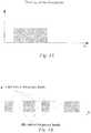
- Fig. 1Ashows an example of a continuous carrier frequency band.
- these communication devicescan only reduce the communication quality requirements (for example, reducing the quantity of services and/or reducing the data rate), and use a continuous carrier frequency band less than the designated band degree of the power line for communication.
- US 2005/0078803 A1relates to a multicarrier communication operable to select carriers on the basis of a SN-ratio and the balancing of the transmission line in a multicarrier communication using a balanced transmission line.
- US 2009/0190673 A1relates to a power line apparatus, an integrated circuit for power line communication and transmission/reception methods.
- Provided in the embodiments of the present inventionare a method and device for communication through a power line, which can guarantee the communication quality requirements of a communication device.
- a method for communication through a power linecomprises: continuously sending a pilot signal with a predetermined level over each of a plurality of carrier frequency bands of a power line, wherein the plurality of carrier frequency bands are discrete from each other; and sending data over each of the plurality of carrier frequency bands.
- the data sent over each of the plurality of carrier frequency bandsrespectively belongs to different services.
- a method for communication through a power linecomprises: receiving a pilot signal and data from each of a plurality of carrier frequency bands of a power line, wherein the plurality of carrier frequency bands are discrete from each other; calculating a level value of the pilot signal received from each of the plurality of carrier frequency bands; and for each of the plurality of carrier frequency bands, performing automatic gain control on the data received from that carrier frequency band according to the calculated level value of the pilot signal received from that carrier frequency band.
- the data received from each of the plurality of carrier frequency bandsrespectively belong to different services.
- a device for communication through a power linecomprises: a sending module for continuously sending a pilot signal with a predetermined level over each of a plurality of carrier frequency bands of a power line, wherein the plurality of carrier frequency bands are discrete from each other; and a transmission module for sending data over each of the plurality of carrier frequency bands.
- the data sent over each of the plurality of carrier frequency bandsrespectively belong to different services.
- a device for communication through a power linecomprises: a receiving module for receiving a pilot signal and data from each of a plurality of carrier frequency bands of a power line, wherein the plurality of carrier frequency bands are discrete from each other; a calculation module for calculating a level value of the pilot signal received from each of the plurality of carrier frequency bands; and a gain control module for, for each of the plurality of carrier frequency bands, performing automatic gain control on the data received from that carrier frequency band according to the calculated level value of the pilot signal received from that carrier frequency band.
- the data received from each of the plurality of carrier frequency bandsrespectively belong to different services.
- the solution of the embodiments of the present inventioncombines a plurality of carrier frequency bands discrete from each other of a power line for communication to meet the bandwidth requirements required by the communication, and sends a pilot signal over each of the plurality of carrier frequency bands which are discrete from each other, so that a communication device serving as a receiver can perform gain control on data received from each of the plurality of carrier frequency bands so as to meet signal level requirements based on a level value of the pilot signal sent over each of the plurality of carrier frequency bands. Therefore, compared with the related art, the solution of the embodiments of the present invention can guarantee the communication quality requirements of a communication device.
- a power line carrier communication system 100for example, comprises a communication device 110, a communication device 120, a communication device 130, a communication device 140 and a power line 150 connecting each of the communication devices, wherein the communication device 110, the communication device 120, the communication device 130, and the communication device 140 can perform mutual communication through the power line 150.
- data sent out by a communication devicecan be regarded as data of a power line communication user.
- the user datacan comprise a single service, and can also comprise a variety of different services.
- FIG. 3shows a flowchart of a method for communication through a power line according to an embodiment of the present invention.
- the method of this embodimentis described in detail by taking the communication device 110 sending data to the communication device 130 through the power line 150 as an example, and it is assumed that the bandwidth required to send the data by the communication device 110 to the communication device 130 is K.
- step S300if an unused carrier frequency band with the bandwidth thereof no less than K does not exist in the power line 150, the communication device 110 and the communication device 130 acquire unoccupied carrier frequency bands on the power line 150, and select a plurality of carrier frequency bands PD therefrom, wherein the total bandwidth of the plurality of carrier frequency bands PD is greater than or equal to K.
- the plurality of carrier frequency bands PDare discrete from each other, for example, the plurality of carrier frequency bands PD are separated from each other by occupied carrier frequency bands.
- the interval between the plurality of carrier frequency bands PD and the occupied carrier frequency bandsalso meets the communication interference requirements.
- the unoccupied carrier frequency bandscan be learnt in advance by each of the communication devices, or can be learnt by means of detecting a signal on the power line.
- step S304the communication device 110 continuously sends a pilot signal having a predetermined level over each of the plurality of carrier frequency bands PD of the power line 150.
- step S308the communication device 110 sends data to be transmitted to the communication device 130 over each of the plurality of carrier frequency bands PD of the power line 150, wherein the data can be, for example, different service data of the same power line communication user.
- step S312the communication device 130 receives the pilot signal and the data sent by the communication device 110 from each of the plurality of carrier frequency bands PD of the power line 150.
- these carrier frequency bandshave been learnt in advance.
- the communication device 130can be informed of these carrier frequency bands in advance, and can also learn same by means of detecting the signal on the power line.
- step S316the communication device 130 calculates a level value of the pilot signal received from each of the plurality of carrier frequency bands PD.
- step S320the communication device 130 performs, for each of the plurality of carrier frequency bands PD, automatic gain control on the data received from that carrier frequency band PD according to the level value of the pilot signal received from that carrier frequency band PD, so that the signal level of the data meets the predetermined signal level requirement.
- the communication device 130can further perform subsequent processing on the received data, such as demodulation and decoding.
- the solution of the embodimentscombines a plurality of carrier frequency bands discrete from each other of the power line 150 for communication to meet the bandwidth requirements required by communication, and sends a pilot signal over each of the plurality of carrier frequency bands which are discrete from each other, so that the communication device 130 serving as a receiver can perform automatic gain control on data received from each of the plurality of carrier frequency bands so as to meet signal level requirements based on a level value of the pilot signal sent over each of the plurality of carrier frequency bands. Therefore, the solution of the embodiments can guarantee the communication quality requirements of a communication device.
- the power line carrier communication system 100comprises four communication devices, the present invention is not limited to this. In some other embodiments of the present invention, the number of communication devices comprised in the power line carrier communication system 100 can be less than four or greater than four.
- the communication device 110 and the communication device 130select a plurality of carrier frequency bands for communication from the various unused carrier frequency bands of the power line 150
- the present inventionis not limited to this.
- the communication device 110 and the communication device 130can also select a plurality of carrier frequency bands for communication from the various unused carrier frequency bands of the power line 150.
- the data sent by the communication device 110 over each of the plurality of carrier frequency bands PDmay belong to different services (such as a digital data service, an analog voice service, an analog digital service and a protection signaling service) .
- the plurality of carrier frequency bands PDare discrete from each other, the mutual interference among each service is reduced and even eliminated.
- the communication device 110can also simultaneously send the same data of the same service within several carrier frequency bands of the plurality of carrier frequency bands PD.
- the communication device 130 serving as a receivercan also receive the same data of the same service from other carrier frequency bands in the several carrier frequency bands.
- the communication device 130can only receive that piece of data received from the carrier frequency band with the best signal quality status as receiving data, alternately, the communication device 130 can take the data obtained by performing weighted summation on the plurality of copies of the same data as receiving data.
- the communication device 110can measure the signal quality status of each of the plurality of carrier frequency bands PD, and then the communication device 110 uses an appropriate modulation method to modulate the data to be transmitted over each of the plurality of carrier frequency bands PD according to the measured signal quality status of each of the plurality of carrier frequency bands PD, and finally sends the modulated data over a corresponding carrier frequency band.
- the appropriate modulation methodselects according to the following method: when the signal quality status of the carrier frequency bands is good, using a modulation method capable of obtaining a higher valid data transmission rate; and when the signal quality status of the carrier frequency bands is bad, using a modulation method with a stronger anti-interference capability.
- the modulation method adopted by the data sent over each carrier frequency band PD of the plurality of carrier frequency bands PDis determined based on the signal quality status of the carrier frequency band PDi.
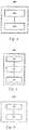
- Fig. 4shows a schematic diagram of a device for communication through a power line according to an embodiment of the present invention.
- the device shown in Fig. 4can be realized using software, hardware (e.g., an integrated circuit, an FPGA, etc.) or a combination of software and hardware, and can be installed in a communication device serving as a sender.
- a device 400 for communication through a power linecan comprise a sending module 410 and a transmission module 420, wherein the sending module 410 can be used for continuously sending a pilot signal with a predetermined level over each of a plurality of carrier frequency bands of a power line, wherein the plurality of carrier frequency bands are discrete from each other, and the transmission module 420 can be used for sending data over each of the plurality of carrier frequency bands, wherein the data sent over each of the plurality of carrier frequency bands may respectively belong to different services, wherein a modulation method adopted by the data sent over each of the plurality of carrier frequency bands is determined based on the signal quality status of the carrier frequency band, and wherein the data sent in several carrier frequency bands of the plurality of carrier frequency bands may be the same data of the same service.
- Fig. 5shows a schematic diagram of a device for communication through a power line according to another embodiment of the present invention.
- the device shown in Fig. 5can be realized using software, hardware (e.g., an integrated circuit, an FPGA, etc.) or a combination of software and hardware, and can be installed in a communication device serving as a receiver.
- softwaree.g., an integrated circuit, an FPGA, etc.
- hardwaree.g., an integrated circuit, an FPGA, etc.
- a device 500 for communication through a power linecan comprise a receiving module 510, a calculation module 520 and a gain control module 530, wherein the receiving module 510 can be used for receiving a pilot signal and data from each of a plurality of carrier frequency bands of a power line, wherein the plurality of carrier frequency bands are discrete from each other.
- the calculation module 520can be used for calculating a level value of the pilot signal received from each of the plurality of carrier frequency bands
- the gain control module 530can be used for, for each of the plurality of carrier frequency bands, performing automatic gain control on the data received from that carrier frequency band according to the calculated level value of the pilot signal received from that carrier frequency band, wherein the data received from each of the plurality of carrier frequency bands may respectively belong to different services, wherein a modulation method adopted by the data received from each of the plurality of carrier frequency bands is determined based on the signal quality status of the carrier frequency band, and wherein the data received from at least one carrier frequency band of the plurality of carrier frequency bands can be the same data of the same service.
- a communication device 600can comprise a memory 610 used for storing an executable instruction and a processor 620, wherein the processor 620 can execute the following operations according to the executable instruction stored in the memory 610: continuously sending a pilot signal with a predetermined level over each of a plurality of carrier frequency bands of a power line, wherein the plurality of carrier frequency bands are discrete from each other; and sending data over each of the plurality of carrier frequency bands, wherein the data sent over each of the plurality of carrier frequency bands may respectively belong to different services, wherein a modulation method adopted by the data sent over each of the plurality of carrier frequency bands is determined based on the signal quality status of the carrier frequency band.
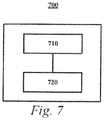
- a communication device 700can comprise a memory 710 used for storing an executable instruction and a processor 720, wherein the processor 720 can execute the following operations according to the executable instruction stored in the memory 710: receiving a pilot signal and data from each of a plurality of carrier frequency bands of a power line, wherein the plurality of carrier frequency bands are discrete from each other; calculating a level value of the pilot signal received from each of the plurality of carrier frequency bands; and for each of the plurality of carrier frequency bands, performing automatic gain control on the data received from that carrier frequency band according to the calculated level value of the pilot signal received from that carrier frequency band, wherein the data received from each of the plurality of carrier frequency bands may respectively belong to different services, wherein a modulation method adopted by the data received from each of the plurality of carrier frequency bands is determined based on the signal quality status of the carrier frequency band.
- Also provided in the embodiments of the present inventionis a machine-readable medium on which an executable instruction is stored, wherein when being executed, the executable instruction causes a machine to realize the operations of the processor 620 or 720.
Landscapes
- Engineering & Computer Science (AREA)
- Signal Processing (AREA)
- Computer Networks & Wireless Communication (AREA)
- Quality & Reliability (AREA)
- Power Engineering (AREA)
- Cable Transmission Systems, Equalization Of Radio And Reduction Of Echo (AREA)
Description
- The present invention relates to the field of power line carrier communications, and particularly to a method and device for communication through a power line.
- Power line carrier communication (PLC) is power system communication taking a power transmission line as a transmission medium of carrier signals. Since a power transmission line has an extremely firm supporting structure, and is provided with more than three conductors (generally having a three-phase good conductor and one or two overhead ground wires), the power transmission line using a power frequency current to transmit carrier signals while transporting same is not only economical but also reliable. Therefore, power line carrier communication has become a typical communication means preferentially adopted by the electric power sector.
- In the existing solution of power line carrier communication, a communication device uses the continuous carrier frequency band of a power line to transmit data of various services, and the bandwidth of the continuous carrier frequency band is sufficient to guarantee the communication quality requirements of the communication device.
Fig. 1A shows an example of a continuous carrier frequency band. - However, with the increase of communication devices using a power line for communication, a certain amount of occupied frequency bands are distributed on the power line in a communication frequency band available for the whole power line, wherein each occupied frequency band itself is a continuous carrier frequency band, and various occupied frequency bands are independent from each other. Thus, most parts of the communication frequency band available for the whole power line are used simultaneously. In such a situation, if certain communication devices still expect to use a certain continuous carrier frequency band having a designated band degree (or bandwidth) of the power line to transmit data, a continuous carrier frequency band no less than the designated band degree cannot be found in unoccupied carrier frequency bands (as shown in
Fig. 1B ) of the power line for use by these communication devices. In this case, these communication devices can only reduce the communication quality requirements (for example, reducing the quantity of services and/or reducing the data rate), and use a continuous carrier frequency band less than the designated band degree of the power line for communication.US 2005/0078803 A1 relates to a multicarrier communication operable to select carriers on the basis of a SN-ratio and the balancing of the transmission line in a multicarrier communication using a balanced transmission line.US 2009/0190673 A1 relates to a power line apparatus, an integrated circuit for power line communication and transmission/reception methods. - Provided in the embodiments of the present invention are a method and device for communication through a power line, which can guarantee the communication quality requirements of a communication device.
- A method for communication through a power line according to the embodiments of the present invention comprises: continuously sending a pilot signal with a predetermined level over each of a plurality of carrier frequency bands of a power line, wherein the plurality of carrier frequency bands are discrete from each other; and sending data over each of the plurality of carrier frequency bands.
- In one particular implementation, the data sent over each of the plurality of carrier frequency bands respectively belongs to different services.
- A method for communication through a power line according to the embodiments of the present invention comprises: receiving a pilot signal and data from each of a plurality of carrier frequency bands of a power line, wherein the plurality of carrier frequency bands are discrete from each other; calculating a level value of the pilot signal received from each of the plurality of carrier frequency bands; and for each of the plurality of carrier frequency bands, performing automatic gain control on the data received from that carrier frequency band according to the calculated level value of the pilot signal received from that carrier frequency band.
- In one particular implementation, the data received from each of the plurality of carrier frequency bands respectively belong to different services.
- A device for communication through a power line according to the embodiments of the present invention comprises: a sending module for continuously sending a pilot signal with a predetermined level over each of a plurality of carrier frequency bands of a power line, wherein the plurality of carrier frequency bands are discrete from each other; and a transmission module for sending data over each of the plurality of carrier frequency bands.
- In one particular implementation, the data sent over each of the plurality of carrier frequency bands respectively belong to different services.
- A device for communication through a power line according to the embodiments of the present invention comprises: a receiving module for receiving a pilot signal and data from each of a plurality of carrier frequency bands of a power line, wherein the plurality of carrier frequency bands are discrete from each other; a calculation module for calculating a level value of the pilot signal received from each of the plurality of carrier frequency bands; and a gain control module for, for each of the plurality of carrier frequency bands, performing automatic gain control on the data received from that carrier frequency band according to the calculated level value of the pilot signal received from that carrier frequency band.
- In one particular implementation, the data received from each of the plurality of carrier frequency bands respectively belong to different services.
- From the description above, it can be seen that the solution of the embodiments of the present invention combines a plurality of carrier frequency bands discrete from each other of a power line for communication to meet the bandwidth requirements required by the communication, and sends a pilot signal over each of the plurality of carrier frequency bands which are discrete from each other, so that a communication device serving as a receiver can perform gain control on data received from each of the plurality of carrier frequency bands so as to meet signal level requirements based on a level value of the pilot signal sent over each of the plurality of carrier frequency bands. Therefore, compared with the related art, the solution of the embodiments of the present invention can guarantee the communication quality requirements of a communication device.
- The other features, characteristics, advantages and benefits of the present invention will become more apparent by way of the detailed description hereinbelow in conjunction with the accompanying drawings.
Fig. 1A shows an example of a continuous carrier frequency band.Fig. 1B shows a schematic diagram of carrier frequency bands of a power line.Fig. 2 shows a schematic diagram of a power line carrier communication system according to an embodiment of the present invention.Fig. 3 shows a flowchart of a method for communication through a power line according to an embodiment of the present invention.Fig. 4 shows a flowchart of a device for communication through a power line according to an embodiment of the present invention.Fig. 5 shows a flowchart of a device for communication through a power line according to another embodiment of the present invention.Fig. 6 shows a schematic diagram of a communication device according to an embodiment of the present invention.Fig. 7 shows a schematic diagram of a communication device according to another embodiment of the present invention.- Various embodiments of the present invention will be described below in detail in conjunction with the accompanying drawings.
- Now referring to
Fig. 2 , it shows a schematic diagram of a power line carrier communication system according to an embodiment of the present invention. As shown inFig. 2 , a power linecarrier communication system 100, for example, comprises acommunication device 110, acommunication device 120, acommunication device 130, acommunication device 140 and apower line 150 connecting each of the communication devices, wherein thecommunication device 110, thecommunication device 120, thecommunication device 130, and thecommunication device 140 can perform mutual communication through thepower line 150. Here, data sent out by a communication device can be regarded as data of a power line communication user. The user data can comprise a single service, and can also comprise a variety of different services. - Now referring to
Fig. 3. Fig. 3 shows a flowchart of a method for communication through a power line according to an embodiment of the present invention. Here, the method of this embodiment is described in detail by taking thecommunication device 110 sending data to thecommunication device 130 through thepower line 150 as an example, and it is assumed that the bandwidth required to send the data by thecommunication device 110 to thecommunication device 130 is K. - As shown in
Fig. 3 , in step S300, if an unused carrier frequency band with the bandwidth thereof no less than K does not exist in thepower line 150, thecommunication device 110 and thecommunication device 130 acquire unoccupied carrier frequency bands on thepower line 150, and select a plurality of carrier frequency bands PD therefrom, wherein the total bandwidth of the plurality of carrier frequency bands PD is greater than or equal to K. Apparently, the plurality of carrier frequency bands PD are discrete from each other, for example, the plurality of carrier frequency bands PD are separated from each other by occupied carrier frequency bands. The interval between the plurality of carrier frequency bands PD and the occupied carrier frequency bands also meets the communication interference requirements. In an embodiment of the present invention, the unoccupied carrier frequency bands can be learnt in advance by each of the communication devices, or can be learnt by means of detecting a signal on the power line. - In step S304, the
communication device 110 continuously sends a pilot signal having a predetermined level over each of the plurality of carrier frequency bands PD of thepower line 150. - In step S308, the
communication device 110 sends data to be transmitted to thecommunication device 130 over each of the plurality of carrier frequency bands PD of thepower line 150, wherein the data can be, for example, different service data of the same power line communication user. - In step S312, the
communication device 130 receives the pilot signal and the data sent by thecommunication device 110 from each of the plurality of carrier frequency bands PD of thepower line 150. For thecommunication device 130, these carrier frequency bands have been learnt in advance. As stated above, thecommunication device 130 can be informed of these carrier frequency bands in advance, and can also learn same by means of detecting the signal on the power line. - In step S316, the
communication device 130 calculates a level value of the pilot signal received from each of the plurality of carrier frequency bands PD. - In step S320, the
communication device 130 performs, for each of the plurality of carrier frequency bands PD, automatic gain control on the data received from that carrier frequency band PD according to the level value of the pilot signal received from that carrier frequency band PD, so that the signal level of the data meets the predetermined signal level requirement. After performing automatic gain control on the received data, thecommunication device 130 can further perform subsequent processing on the received data, such as demodulation and decoding. - From the description above, it can be seen that the solution of the embodiments combines a plurality of carrier frequency bands discrete from each other of the
power line 150 for communication to meet the bandwidth requirements required by communication, and sends a pilot signal over each of the plurality of carrier frequency bands which are discrete from each other, so that thecommunication device 130 serving as a receiver can perform automatic gain control on data received from each of the plurality of carrier frequency bands so as to meet signal level requirements based on a level value of the pilot signal sent over each of the plurality of carrier frequency bands. Therefore, the solution of the embodiments can guarantee the communication quality requirements of a communication device. - A person skilled in the art should understand that, although in the above embodiments, the power line
carrier communication system 100 comprises four communication devices, the present invention is not limited to this. In some other embodiments of the present invention, the number of communication devices comprised in the power linecarrier communication system 100 can be less than four or greater than four. - A person skilled in the art should understand that, although in the above embodiments, insofar as an unused carrier frequency band with the bandwidth thereof no less than K does not exist in the
power line 150, thecommunication device 110 and thecommunication device 130 then select a plurality of carrier frequency bands for communication from the various unused carrier frequency bands of thepower line 150, the present invention is not limited to this. In some other embodiments of the present invention, even if an unused carrier frequency band with the bandwidth thereof no less than K exists in thepower line 150, thecommunication device 110 and thecommunication device 130 can also select a plurality of carrier frequency bands for communication from the various unused carrier frequency bands of thepower line 150. - A person skilled in the art should understand that, the data sent by the
communication device 110 over each of the plurality of carrier frequency bands PD may belong to different services (such as a digital data service, an analog voice service, an analog digital service and a protection signaling service) . In this situation, since the plurality of carrier frequency bands PD are discrete from each other, the mutual interference among each service is reduced and even eliminated. - A person skilled in the art should understand that, the
communication device 110 can also simultaneously send the same data of the same service within several carrier frequency bands of the plurality of carrier frequency bands PD. Thus, even if certain carrier frequency bands in the several carrier frequency bands cannot work due to interference, thecommunication device 130 serving as a receiver can also receive the same data of the same service from other carrier frequency bands in the several carrier frequency bands. Here, if thecommunication device 130 receives a plurality of copies of the same data of the same service from two or more than two carrier frequency bands, thecommunication device 130 can only receive that piece of data received from the carrier frequency band with the best signal quality status as receiving data, alternately, thecommunication device 130 can take the data obtained by performing weighted summation on the plurality of copies of the same data as receiving data. - A person skilled in the art should understand that, before the
communication device 110 sends data over each of the plurality of carrier frequency bands PD of thepower line 150, thecommunication device 110 can measure the signal quality status of each of the plurality of carrier frequency bands PD, and then thecommunication device 110 uses an appropriate modulation method to modulate the data to be transmitted over each of the plurality of carrier frequency bands PD according to the measured signal quality status of each of the plurality of carrier frequency bands PD, and finally sends the modulated data over a corresponding carrier frequency band. The appropriate modulation method selects according to the following method: when the signal quality status of the carrier frequency bands is good, using a modulation method capable of obtaining a higher valid data transmission rate; and when the signal quality status of the carrier frequency bands is bad, using a modulation method with a stronger anti-interference capability. In other words, the modulation method adopted by the data sent over each carrier frequency band PD of the plurality of carrier frequency bands PD is determined based on the signal quality status of the carrier frequency band PDi. - Now referring to
Fig. 4 , it shows a schematic diagram of a device for communication through a power line according to an embodiment of the present invention. The device shown inFig. 4 can be realized using software, hardware (e.g., an integrated circuit, an FPGA, etc.) or a combination of software and hardware, and can be installed in a communication device serving as a sender. - As shown in
Fig. 4 , adevice 400 for communication through a power line can comprise a sendingmodule 410 and atransmission module 420, wherein the sendingmodule 410 can be used for continuously sending a pilot signal with a predetermined level over each of a plurality of carrier frequency bands of a power line, wherein the plurality of carrier frequency bands are discrete from each other, and thetransmission module 420 can be used for sending data over each of the plurality of carrier frequency bands,
wherein the data sent over each of the plurality of carrier frequency bands may respectively belong to different services,
wherein a modulation method adopted by the data sent over each of the plurality of carrier frequency bands is determined based on the signal quality status of the carrier frequency band,
and wherein the data sent in several carrier frequency bands of the plurality of carrier frequency bands may be the same data of the same service. - Now referring to
Fig. 5 , it shows a schematic diagram of a device for communication through a power line according to another embodiment of the present invention. The device shown inFig. 5 can be realized using software, hardware (e.g., an integrated circuit, an FPGA, etc.) or a combination of software and hardware, and can be installed in a communication device serving as a receiver. - As shown in
Fig. 5 , adevice 500 for communication through a power line can comprise a receiving module 510, acalculation module 520 and again control module 530, wherein the receiving module 510 can be used for receiving a pilot signal and data from each of a plurality of carrier frequency bands of a power line, wherein the plurality of carrier frequency bands are discrete from each other. Thecalculation module 520 can be used for calculating a level value of the pilot signal received from each of the plurality of carrier frequency bands, and thegain control module 530 can be used for, for each of the plurality of carrier frequency bands, performing automatic gain control on the data received from that carrier frequency band according to the calculated level value of the pilot signal received from that carrier frequency band,
wherein the data received from each of the plurality of carrier frequency bands may respectively belong to different services,
wherein a modulation method adopted by the data received from each of the plurality of carrier frequency bands is determined based on the signal quality status of the carrier frequency band,
and wherein the data received from at least one carrier frequency band of the plurality of carrier frequency bands can be the same data of the same service. - Now referring to
Fig. 6 , it shows a schematic diagram of a communication device according to an embodiment of the present invention. As shown inFig. 6 , acommunication device 600 can comprise amemory 610 used for storing an executable instruction and aprocessor 620,
wherein theprocessor 620 can execute the following operations according to the executable instruction stored in the memory 610: continuously sending a pilot signal with a predetermined level over each of a plurality of carrier frequency bands of a power line, wherein the plurality of carrier frequency bands are discrete from each other; and sending data over each of the plurality of carrier frequency bands,
wherein the data sent over each of the plurality of carrier frequency bands may respectively belong to different services,
wherein a modulation method adopted by the data sent over each of the plurality of carrier frequency bands is determined based on the signal quality status of the carrier frequency band. - Now referring to
Fig. 7 , it shows a schematic diagram of a communication device according to an embodiment of the present invention. As shown inFig. 7 , a communication device 700 can comprise amemory 710 used for storing an executable instruction and aprocessor 720,
wherein theprocessor 720 can execute the following operations according to the executable instruction stored in the memory 710: receiving a pilot signal and data from each of a plurality of carrier frequency bands of a power line, wherein the plurality of carrier frequency bands are discrete from each other; calculating a level value of the pilot signal received from each of the plurality of carrier frequency bands; and for each of the plurality of carrier frequency bands, performing automatic gain control on the data received from that carrier frequency band according to the calculated level value of the pilot signal received from that carrier frequency band,
wherein the data received from each of the plurality of carrier frequency bands may respectively belong to different services,
wherein a modulation method adopted by the data received from each of the plurality of carrier frequency bands is determined based on the signal quality status of the carrier frequency band. - Also provided in the embodiments of the present invention is a machine-readable medium on which an executable instruction is stored, wherein when being executed, the executable instruction causes a machine to realize the operations of the
processor - A person skilled in the art should understand that various variations and modifications can be made to the above various embodiments without departing from the essence of the invention. Therefore, the protection scope of the present invention should be defined by the appended claims.
Claims (13)
- A method for communication through a power line (150),characterized by:obtaining a plurality of unoccupied carrier frequency bands on a power line (150), wherein the plurality of carrier frequency bands are discrete from each other (S300);continuously sending a pilot signal with a predetermined level over each of the plurality of carrier frequency bands (S304); andsending data over each of the plurality of carrier frequency bands (S308), wherein the data is data of the same power line communication user.
- The method as claimed in claim 1,characterized in that
the data sent over each of the plurality of carrier frequency bands respectively belong to different services of the same power line communication user. - The method as claimed in claim 1,characterized in that
the data sent over at least two carrier frequency bands of the plurality of carrier frequency bands are identical to each other. - The method as claimed in claim 1,characterized in that a modulation method adopted by the data sent over each of the plurality of carrier frequency bands is determined based on the signal quality status of the carrier frequency band.
- A method for communication through a power line (150),characterized by:acquiring a plurality of carrier frequency bands used for transmitting data of the same user on a power line (150), wherein the plurality of carrier frequency bands are discrete from each other (S300);receiving (S312) a pilot signal and data from each of the plurality of carrier frequency bands of the power line (150);calculating a level value of the pilot signal received from each of the plurality of carrier frequency bands (S316); andfor each of the plurality of carrier frequency bands, performing automatic gain control on the data received from that carrier frequency band according to the calculated level value of the pilot signal received from that carrier frequency band (S320).
- The method as claimed in claim 5,characterized in that
the data received from each of the plurality of carrier frequency bands respectively belong to different services of the same user. - The method as claimed in claim 5,characterized in that
the data sent over at least two carrier frequency bands of the plurality of carrier frequency bands are identical to each other, and the method further comprises:
obtaining the required data based on the signal acquired from the at least two carrier frequency bands. - The method as claimed in claim 1 or 5,characterized in that
the plurality of carrier frequency bands are separated by occupied carrier frequency bands. - A device (400) for communication through a power line (150),characterized by:a sending module (410) for continuously sending a pilot signal with a predetermined level over each of a plurality of carrier frequency bands of a power line (150), wherein the plurality of carrier frequency bands are carrier frequency bands obtained in advance and discrete from each other, anda transmission module (420) for sending data over each of the plurality of carrier frequency bands, wherein the data is data of the same power line communication user.
- The device (400) as claimed in claim 9,characterized in that
the data sent over each of the plurality of carrier frequency bands respectively belong to different services of the same user. - The device (400) as claimed in claim 9,characterized in that
the data sent over at least two carrier frequency bands of the plurality of carrier frequency bands are identical to each other. - A device (500) for communication through a power line (150),characterized by:a receiving module (510) for receiving a pilot signal and data from each of a plurality of carrier frequency bands of a power line (150), wherein the plurality of carrier frequency bands are carrier frequency bands obtained in advance and discrete from each other;a calculation module (520) for calculating a level value of the pilot signal received from each of the plurality of carrier frequency bands; anda gain control module (530) for, for each of the plurality of carrier frequency bands, performing automatic gain control on the data received from that carrier frequency band according to the calculated level value of the pilot signal received from that carrier frequency band.
- The device as claimed in claim 12,characterized in that
the data received from each of the plurality of carrier frequency bands respectively belong to different services.
Applications Claiming Priority (2)
| Application Number | Priority Date | Filing Date | Title |
|---|---|---|---|
| CN201310065005 | 2013-02-28 | ||
| PCT/CN2013/072245WO2014131204A1 (en) | 2013-02-28 | 2013-03-06 | Method and apparatus for communication through power line |
Publications (3)
| Publication Number | Publication Date |
|---|---|
| EP2963838A1 EP2963838A1 (en) | 2016-01-06 |
| EP2963838A4 EP2963838A4 (en) | 2016-10-26 |
| EP2963838B1true EP2963838B1 (en) | 2019-05-01 |
Family
ID=51427498
Family Applications (1)
| Application Number | Title | Priority Date | Filing Date |
|---|---|---|---|
| EP13876649.8AActiveEP2963838B1 (en) | 2013-02-28 | 2013-03-06 | Method and apparatus for communication through power line |
Country Status (6)
| Country | Link |
|---|---|
| EP (1) | EP2963838B1 (en) |
| CN (1) | CN104995847B (en) |
| BR (1) | BR112015020599B1 (en) |
| ES (1) | ES2737801T3 (en) |
| MX (1) | MX342367B (en) |
| WO (1) | WO2014131204A1 (en) |
Families Citing this family (3)
| Publication number | Priority date | Publication date | Assignee | Title |
|---|---|---|---|---|
| CN107529690A (en)* | 2017-08-26 | 2018-01-02 | 蓝洞物联科技(宁波)有限公司 | A kind of intelligent adaptive power-line carrier communication method |
| CN107529689A (en)* | 2017-08-26 | 2018-01-02 | 康体佳智能科技(深圳)有限公司 | A kind of power-line carrier communication method of intelligent selection signalling channel |
| CN109979183B (en)* | 2019-05-05 | 2024-04-09 | 长沙优力电驱动系统有限公司 | Signal transmitting method, receiving method and signal transmission equipment based on current carrier |
Family Cites Families (15)
| Publication number | Priority date | Publication date | Assignee | Title |
|---|---|---|---|---|
| US5519731A (en)* | 1994-04-14 | 1996-05-21 | Amati Communications Corporation | ADSL compatible discrete multi-tone apparatus for mitigation of T1 noise |
| KR20020007441A (en)* | 2000-07-13 | 2002-01-29 | 이기원 | System for power line communication on multi-carrier modulation |
| WO2005029803A2 (en)* | 2003-09-19 | 2005-03-31 | Matsushita Electric Industrial Co., Ltd. | Multicarrier communication method, system and apparatus |
| JP2006352267A (en)* | 2005-06-13 | 2006-12-28 | Matsushita Electric Ind Co Ltd | TRANSMISSION DEVICE, RECEPTION DEVICE, TRANSMISSION METHOD, AND RECEPTION METHOD |
| US8798214B2 (en)* | 2007-11-14 | 2014-08-05 | Qualcomm Incorporated | Minimum finger low-power demodulator for wireless communication |
| US8310963B2 (en)* | 2008-06-24 | 2012-11-13 | Adc Telecommunications, Inc. | System and method for synchronized time-division duplex signal switching |
| US8208414B2 (en)* | 2008-06-24 | 2012-06-26 | Lgc Wireless, Inc. | System and method for configurable time-division duplex interface |
| ES2349515B2 (en)* | 2008-07-14 | 2011-07-15 | Marvell Hispania, S.L. (Sociedad Unipersonal) | MULTIBAND DATA TRANSMISSION PROCEDURE. |
| CN102255841B (en)* | 2010-05-17 | 2016-03-30 | 中兴通讯股份有限公司 | Broadcast Control Channel, data channel resource mapping method and device |
| US8582551B2 (en)* | 2010-05-26 | 2013-11-12 | Intel Corporation | Device, system and method of wireless communication over non-contiguous channels |
| WO2012036378A2 (en)* | 2010-09-17 | 2012-03-22 | 엘지전자 주식회사 | Method for resource scheduling using a carrier aggregation technique |
| CN102752757B (en)* | 2011-04-19 | 2015-06-17 | 深圳清华大学研究院 | Method for optimizing frequency spectrum allocation according to minimal waste criterion in frequency spectrum aggregation process |
| CN102437988B (en)* | 2011-08-24 | 2018-01-30 | 中兴通讯股份有限公司 | A kind of frequency spectrum use method and device of digital radio broadcast TV |
| CN102547718B (en)* | 2012-01-19 | 2016-01-20 | 北京邮电大学 | Based on the discrete spectrum polymerization that maximum space is preferential |
| CN102843700B (en)* | 2012-08-21 | 2016-08-10 | 国网电力科学研究院 | The discharge model of a kind of LTE230M electric power radio communication and implementation method |
- 2013
- 2013-03-06EPEP13876649.8Apatent/EP2963838B1/enactiveActive
- 2013-03-06WOPCT/CN2013/072245patent/WO2014131204A1/enactiveApplication Filing
- 2013-03-06CNCN201380073127.XApatent/CN104995847B/ennot_activeExpired - Fee Related
- 2013-03-06MXMX2015010969Apatent/MX342367B/enactiveIP Right Grant
- 2013-03-06ESES13876649Tpatent/ES2737801T3/enactiveActive
- 2013-03-06BRBR112015020599-2Apatent/BR112015020599B1/ennot_activeIP Right Cessation
Non-Patent Citations (1)
| Title |
|---|
| None* |
Also Published As
| Publication number | Publication date |
|---|---|
| BR112015020599B1 (en) | 2022-10-11 |
| BR112015020599A2 (en) | 2017-07-18 |
| MX2015010969A (en) | 2015-10-26 |
| CN104995847A (en) | 2015-10-21 |
| WO2014131204A1 (en) | 2014-09-04 |
| CN104995847B (en) | 2018-03-27 |
| EP2963838A4 (en) | 2016-10-26 |
| ES2737801T3 (en) | 2020-01-16 |
| MX342367B (en) | 2016-09-27 |
| EP2963838A1 (en) | 2016-01-06 |
Similar Documents
| Publication | Publication Date | Title |
|---|---|---|
| US12057933B2 (en) | Scheduling in communication systems with multiple service types | |
| KR101206402B1 (en) | Distributed antenna system and its data transmission method and central controller | |
| EP3644672A1 (en) | Method, device, and storage medium for configuring starting symbol position of uplink data channel | |
| US20170063586A1 (en) | Method for transmitting data between baseband unit bbu and remote radio unit rru, and data transmission apparatus | |
| US20230033208A1 (en) | Selection of decoding level at signal forwarding devices | |
| EA026041B1 (en) | Wireless communication system, communication apparatus, wireless communication method and terminal apparatus | |
| WO2020171744A1 (en) | Methods and units of a base station system for transmission over fronthaul links | |
| EP2963838B1 (en) | Method and apparatus for communication through power line | |
| CN101754347A (en) | CQI estimation method, system and device during multi-stream beamforming transmission | |
| JP2020512727A (en) | Scheduling method, base station, and terminal | |
| US20230318721A1 (en) | Receiver, transmitter, device, methods and computer programs for feedback sensing | |
| CN113285741A (en) | Signal transmission method and related equipment | |
| US12431941B2 (en) | Transmission configuration method and apparatus for multiple transmission and reception points (TRPs) | |
| EP3425807B1 (en) | Wireless communication system and communication method | |
| EP2456111A1 (en) | Radio base station apparatus and modulating/coding scheme selecting method | |
| CN112039808A (en) | Channel estimation method and device | |
| US10826593B2 (en) | Method of placing a node in a wireless communication into a standby mode, as well as the corresponding node | |
| CN115714702B (en) | Data processing method, device, electronic equipment and computer storage medium | |
| KR20150136222A (en) | Method and apparatus for processing signal | |
| JP6455781B2 (en) | Wireless communication apparatus and channel occupation state detection method | |
| US9319102B2 (en) | Communication apparatus, communication system, communication method, and storage medium | |
| CN109150430A (en) | A kind of data transmission method and device | |
| KR102353972B1 (en) | Apparatus and method for demodulating signal based on combining subframes in wireless communication system | |
| KR101944506B1 (en) | Method for detecting uplink signal in base station | |
| CN115336221B (en) | Method and device for determining Channel State Information (CSI) feedback |
Legal Events
| Date | Code | Title | Description |
|---|---|---|---|
| PUAI | Public reference made under article 153(3) epc to a published international application that has entered the european phase | Free format text:ORIGINAL CODE: 0009012 | |
| 17P | Request for examination filed | Effective date:20150925 | |
| AK | Designated contracting states | Kind code of ref document:A1 Designated state(s):AL AT BE BG CH CY CZ DE DK EE ES FI FR GB GR HR HU IE IS IT LI LT LU LV MC MK MT NL NO PL PT RO RS SE SI SK SM TR | |
| AX | Request for extension of the european patent | Extension state:BA ME | |
| DAX | Request for extension of the european patent (deleted) | ||
| A4 | Supplementary search report drawn up and despatched | Effective date:20160923 | |
| RIC1 | Information provided on ipc code assigned before grant | Ipc:H04L 5/00 20060101ALI20160919BHEP Ipc:H04B 3/54 20060101AFI20160919BHEP Ipc:H04L 1/00 20060101ALI20160919BHEP | |
| RAP1 | Party data changed (applicant data changed or rights of an application transferred) | Owner name:SIEMENS AKTIENGESELLSCHAFT | |
| GRAP | Despatch of communication of intention to grant a patent | Free format text:ORIGINAL CODE: EPIDOSNIGR1 | |
| STAA | Information on the status of an ep patent application or granted ep patent | Free format text:STATUS: GRANT OF PATENT IS INTENDED | |
| INTG | Intention to grant announced | Effective date:20181029 | |
| GRAS | Grant fee paid | Free format text:ORIGINAL CODE: EPIDOSNIGR3 | |
| GRAA | (expected) grant | Free format text:ORIGINAL CODE: 0009210 | |
| STAA | Information on the status of an ep patent application or granted ep patent | Free format text:STATUS: THE PATENT HAS BEEN GRANTED | |
| AK | Designated contracting states | Kind code of ref document:B1 Designated state(s):AL AT BE BG CH CY CZ DE DK EE ES FI FR GB GR HR HU IE IS IT LI LT LU LV MC MK MT NL NO PL PT RO RS SE SI SK SM TR | |
| REG | Reference to a national code | Ref country code:GB Ref legal event code:FG4D | |
| REG | Reference to a national code | Ref country code:CH Ref legal event code:EP Ref country code:AT Ref legal event code:REF Ref document number:1128306 Country of ref document:AT Kind code of ref document:T Effective date:20190515 | |
| REG | Reference to a national code | Ref country code:DE Ref legal event code:R096 Ref document number:602013054835 Country of ref document:DE | |
| REG | Reference to a national code | Ref country code:IE Ref legal event code:FG4D | |
| REG | Reference to a national code | Ref country code:CH Ref legal event code:NV Representative=s name:SIEMENS SCHWEIZ AG, CH | |
| REG | Reference to a national code | Ref country code:NL Ref legal event code:MP Effective date:20190501 | |
| REG | Reference to a national code | Ref country code:LT Ref legal event code:MG4D | |
| PG25 | Lapsed in a contracting state [announced via postgrant information from national office to epo] | Ref country code:LT Free format text:LAPSE BECAUSE OF FAILURE TO SUBMIT A TRANSLATION OF THE DESCRIPTION OR TO PAY THE FEE WITHIN THE PRESCRIBED TIME-LIMIT Effective date:20190501 Ref country code:NL Free format text:LAPSE BECAUSE OF FAILURE TO SUBMIT A TRANSLATION OF THE DESCRIPTION OR TO PAY THE FEE WITHIN THE PRESCRIBED TIME-LIMIT Effective date:20190501 Ref country code:FI Free format text:LAPSE BECAUSE OF FAILURE TO SUBMIT A TRANSLATION OF THE DESCRIPTION OR TO PAY THE FEE WITHIN THE PRESCRIBED TIME-LIMIT Effective date:20190501 Ref country code:PT Free format text:LAPSE BECAUSE OF FAILURE TO SUBMIT A TRANSLATION OF THE DESCRIPTION OR TO PAY THE FEE WITHIN THE PRESCRIBED TIME-LIMIT Effective date:20190901 Ref country code:SE Free format text:LAPSE BECAUSE OF FAILURE TO SUBMIT A TRANSLATION OF THE DESCRIPTION OR TO PAY THE FEE WITHIN THE PRESCRIBED TIME-LIMIT Effective date:20190501 Ref country code:NO Free format text:LAPSE BECAUSE OF FAILURE TO SUBMIT A TRANSLATION OF THE DESCRIPTION OR TO PAY THE FEE WITHIN THE PRESCRIBED TIME-LIMIT Effective date:20190801 Ref country code:HR Free format text:LAPSE BECAUSE OF FAILURE TO SUBMIT A TRANSLATION OF THE DESCRIPTION OR TO PAY THE FEE WITHIN THE PRESCRIBED TIME-LIMIT Effective date:20190501 Ref country code:AL Free format text:LAPSE BECAUSE OF FAILURE TO SUBMIT A TRANSLATION OF THE DESCRIPTION OR TO PAY THE FEE WITHIN THE PRESCRIBED TIME-LIMIT Effective date:20190501 | |
| PG25 | Lapsed in a contracting state [announced via postgrant information from national office to epo] | Ref country code:BG Free format text:LAPSE BECAUSE OF FAILURE TO SUBMIT A TRANSLATION OF THE DESCRIPTION OR TO PAY THE FEE WITHIN THE PRESCRIBED TIME-LIMIT Effective date:20190801 Ref country code:GR Free format text:LAPSE BECAUSE OF FAILURE TO SUBMIT A TRANSLATION OF THE DESCRIPTION OR TO PAY THE FEE WITHIN THE PRESCRIBED TIME-LIMIT Effective date:20190802 Ref country code:RS Free format text:LAPSE BECAUSE OF FAILURE TO SUBMIT A TRANSLATION OF THE DESCRIPTION OR TO PAY THE FEE WITHIN THE PRESCRIBED TIME-LIMIT Effective date:20190501 Ref country code:LV Free format text:LAPSE BECAUSE OF FAILURE TO SUBMIT A TRANSLATION OF THE DESCRIPTION OR TO PAY THE FEE WITHIN THE PRESCRIBED TIME-LIMIT Effective date:20190501 | |
| REG | Reference to a national code | Ref country code:AT Ref legal event code:MK05 Ref document number:1128306 Country of ref document:AT Kind code of ref document:T Effective date:20190501 | |
| PG25 | Lapsed in a contracting state [announced via postgrant information from national office to epo] | Ref country code:IS Free format text:LAPSE BECAUSE OF FAILURE TO SUBMIT A TRANSLATION OF THE DESCRIPTION OR TO PAY THE FEE WITHIN THE PRESCRIBED TIME-LIMIT Effective date:20190901 | |
| REG | Reference to a national code | Ref country code:ES Ref legal event code:FG2A Ref document number:2737801 Country of ref document:ES Kind code of ref document:T3 Effective date:20200116 | |
| PG25 | Lapsed in a contracting state [announced via postgrant information from national office to epo] | Ref country code:EE Free format text:LAPSE BECAUSE OF FAILURE TO SUBMIT A TRANSLATION OF THE DESCRIPTION OR TO PAY THE FEE WITHIN THE PRESCRIBED TIME-LIMIT Effective date:20190501 Ref country code:DK Free format text:LAPSE BECAUSE OF FAILURE TO SUBMIT A TRANSLATION OF THE DESCRIPTION OR TO PAY THE FEE WITHIN THE PRESCRIBED TIME-LIMIT Effective date:20190501 Ref country code:SK Free format text:LAPSE BECAUSE OF FAILURE TO SUBMIT A TRANSLATION OF THE DESCRIPTION OR TO PAY THE FEE WITHIN THE PRESCRIBED TIME-LIMIT Effective date:20190501 Ref country code:AT Free format text:LAPSE BECAUSE OF FAILURE TO SUBMIT A TRANSLATION OF THE DESCRIPTION OR TO PAY THE FEE WITHIN THE PRESCRIBED TIME-LIMIT Effective date:20190501 Ref country code:CZ Free format text:LAPSE BECAUSE OF FAILURE TO SUBMIT A TRANSLATION OF THE DESCRIPTION OR TO PAY THE FEE WITHIN THE PRESCRIBED TIME-LIMIT Effective date:20190501 Ref country code:RO Free format text:LAPSE BECAUSE OF FAILURE TO SUBMIT A TRANSLATION OF THE DESCRIPTION OR TO PAY THE FEE WITHIN THE PRESCRIBED TIME-LIMIT Effective date:20190501 | |
| REG | Reference to a national code | Ref country code:DE Ref legal event code:R097 Ref document number:602013054835 Country of ref document:DE | |
| PG25 | Lapsed in a contracting state [announced via postgrant information from national office to epo] | Ref country code:SM Free format text:LAPSE BECAUSE OF FAILURE TO SUBMIT A TRANSLATION OF THE DESCRIPTION OR TO PAY THE FEE WITHIN THE PRESCRIBED TIME-LIMIT Effective date:20190501 Ref country code:IT Free format text:LAPSE BECAUSE OF FAILURE TO SUBMIT A TRANSLATION OF THE DESCRIPTION OR TO PAY THE FEE WITHIN THE PRESCRIBED TIME-LIMIT Effective date:20190501 | |
| PLBE | No opposition filed within time limit | Free format text:ORIGINAL CODE: 0009261 | |
| STAA | Information on the status of an ep patent application or granted ep patent | Free format text:STATUS: NO OPPOSITION FILED WITHIN TIME LIMIT | |
| PG25 | Lapsed in a contracting state [announced via postgrant information from national office to epo] | Ref country code:TR Free format text:LAPSE BECAUSE OF FAILURE TO SUBMIT A TRANSLATION OF THE DESCRIPTION OR TO PAY THE FEE WITHIN THE PRESCRIBED TIME-LIMIT Effective date:20190501 | |
| 26N | No opposition filed | Effective date:20200204 | |
| PG25 | Lapsed in a contracting state [announced via postgrant information from national office to epo] | Ref country code:PL Free format text:LAPSE BECAUSE OF FAILURE TO SUBMIT A TRANSLATION OF THE DESCRIPTION OR TO PAY THE FEE WITHIN THE PRESCRIBED TIME-LIMIT Effective date:20190501 | |
| PG25 | Lapsed in a contracting state [announced via postgrant information from national office to epo] | Ref country code:SI Free format text:LAPSE BECAUSE OF FAILURE TO SUBMIT A TRANSLATION OF THE DESCRIPTION OR TO PAY THE FEE WITHIN THE PRESCRIBED TIME-LIMIT Effective date:20190501 | |
| PG25 | Lapsed in a contracting state [announced via postgrant information from national office to epo] | Ref country code:MC Free format text:LAPSE BECAUSE OF FAILURE TO SUBMIT A TRANSLATION OF THE DESCRIPTION OR TO PAY THE FEE WITHIN THE PRESCRIBED TIME-LIMIT Effective date:20190501 | |
| REG | Reference to a national code | Ref country code:BE Ref legal event code:MM Effective date:20200331 | |
| PG25 | Lapsed in a contracting state [announced via postgrant information from national office to epo] | Ref country code:LU Free format text:LAPSE BECAUSE OF NON-PAYMENT OF DUE FEES Effective date:20200306 | |
| PG25 | Lapsed in a contracting state [announced via postgrant information from national office to epo] | Ref country code:IE Free format text:LAPSE BECAUSE OF NON-PAYMENT OF DUE FEES Effective date:20200306 Ref country code:FR Free format text:LAPSE BECAUSE OF NON-PAYMENT OF DUE FEES Effective date:20200331 | |
| PG25 | Lapsed in a contracting state [announced via postgrant information from national office to epo] | Ref country code:BE Free format text:LAPSE BECAUSE OF NON-PAYMENT OF DUE FEES Effective date:20200331 | |
| GBPC | Gb: european patent ceased through non-payment of renewal fee | Effective date:20200306 | |
| PG25 | Lapsed in a contracting state [announced via postgrant information from national office to epo] | Ref country code:GB Free format text:LAPSE BECAUSE OF NON-PAYMENT OF DUE FEES Effective date:20200306 | |
| PG25 | Lapsed in a contracting state [announced via postgrant information from national office to epo] | Ref country code:MT Free format text:LAPSE BECAUSE OF FAILURE TO SUBMIT A TRANSLATION OF THE DESCRIPTION OR TO PAY THE FEE WITHIN THE PRESCRIBED TIME-LIMIT Effective date:20190501 Ref country code:CY Free format text:LAPSE BECAUSE OF FAILURE TO SUBMIT A TRANSLATION OF THE DESCRIPTION OR TO PAY THE FEE WITHIN THE PRESCRIBED TIME-LIMIT Effective date:20190501 | |
| PG25 | Lapsed in a contracting state [announced via postgrant information from national office to epo] | Ref country code:MK Free format text:LAPSE BECAUSE OF FAILURE TO SUBMIT A TRANSLATION OF THE DESCRIPTION OR TO PAY THE FEE WITHIN THE PRESCRIBED TIME-LIMIT Effective date:20190501 | |
| PGFP | Annual fee paid to national office [announced via postgrant information from national office to epo] | Ref country code:ES Payment date:20220629 Year of fee payment:10 | |
| PGFP | Annual fee paid to national office [announced via postgrant information from national office to epo] | Ref country code:CH Payment date:20220613 Year of fee payment:10 | |
| PGFP | Annual fee paid to national office [announced via postgrant information from national office to epo] | Ref country code:DE Payment date:20220620 Year of fee payment:11 | |
| REG | Reference to a national code | Ref country code:CH Ref legal event code:PL | |
| PG25 | Lapsed in a contracting state [announced via postgrant information from national office to epo] | Ref country code:LI Free format text:LAPSE BECAUSE OF NON-PAYMENT OF DUE FEES Effective date:20230331 Ref country code:CH Free format text:LAPSE BECAUSE OF NON-PAYMENT OF DUE FEES Effective date:20230331 | |
| REG | Reference to a national code | Ref country code:ES Ref legal event code:FD2A Effective date:20240503 | |
| PG25 | Lapsed in a contracting state [announced via postgrant information from national office to epo] | Ref country code:ES Free format text:LAPSE BECAUSE OF NON-PAYMENT OF DUE FEES Effective date:20230307 | |
| PG25 | Lapsed in a contracting state [announced via postgrant information from national office to epo] | Ref country code:ES Free format text:LAPSE BECAUSE OF NON-PAYMENT OF DUE FEES Effective date:20230307 | |
| REG | Reference to a national code | Ref country code:DE Ref legal event code:R119 Ref document number:602013054835 Country of ref document:DE | |
| PG25 | Lapsed in a contracting state [announced via postgrant information from national office to epo] | Ref country code:DE Free format text:LAPSE BECAUSE OF NON-PAYMENT OF DUE FEES Effective date:20241001 | |
| PG25 | Lapsed in a contracting state [announced via postgrant information from national office to epo] | Ref country code:DE Free format text:LAPSE BECAUSE OF NON-PAYMENT OF DUE FEES Effective date:20241001 |