EP2962309B1 - Electromagnetically actuated multi-leaf collimator - Google Patents
Electromagnetically actuated multi-leaf collimatorDownload PDFInfo
- Publication number
- EP2962309B1 EP2962309B1EP14757576.5AEP14757576AEP2962309B1EP 2962309 B1EP2962309 B1EP 2962309B1EP 14757576 AEP14757576 AEP 14757576AEP 2962309 B1EP2962309 B1EP 2962309B1
- Authority
- EP
- European Patent Office
- Prior art keywords
- leaf
- mlc
- leaves
- drive
- subset
- Prior art date
- Legal status (The legal status is an assumption and is not a legal conclusion. Google has not performed a legal analysis and makes no representation as to the accuracy of the status listed.)
- Active
Links
Images


Classifications
- A—HUMAN NECESSITIES
- A61—MEDICAL OR VETERINARY SCIENCE; HYGIENE
- A61N—ELECTROTHERAPY; MAGNETOTHERAPY; RADIATION THERAPY; ULTRASOUND THERAPY
- A61N5/00—Radiation therapy
- A61N5/10—X-ray therapy; Gamma-ray therapy; Particle-irradiation therapy
- A61N5/1042—X-ray therapy; Gamma-ray therapy; Particle-irradiation therapy with spatial modulation of the radiation beam within the treatment head
- A61N5/1045—X-ray therapy; Gamma-ray therapy; Particle-irradiation therapy with spatial modulation of the radiation beam within the treatment head using a multi-leaf collimator, e.g. for intensity modulated radiation therapy or IMRT
- G—PHYSICS
- G21—NUCLEAR PHYSICS; NUCLEAR ENGINEERING
- G21K—TECHNIQUES FOR HANDLING PARTICLES OR IONISING RADIATION NOT OTHERWISE PROVIDED FOR; IRRADIATION DEVICES; GAMMA RAY OR X-RAY MICROSCOPES
- G21K1/00—Arrangements for handling particles or ionising radiation, e.g. focusing or moderating
- G21K1/02—Arrangements for handling particles or ionising radiation, e.g. focusing or moderating using diaphragms, collimators
- G21K1/04—Arrangements for handling particles or ionising radiation, e.g. focusing or moderating using diaphragms, collimators using variable diaphragms, shutters, choppers
- G21K1/046—Arrangements for handling particles or ionising radiation, e.g. focusing or moderating using diaphragms, collimators using variable diaphragms, shutters, choppers varying the contour of the field, e.g. multileaf collimators
- A—HUMAN NECESSITIES
- A61—MEDICAL OR VETERINARY SCIENCE; HYGIENE
- A61N—ELECTROTHERAPY; MAGNETOTHERAPY; RADIATION THERAPY; ULTRASOUND THERAPY
- A61N5/00—Radiation therapy
- A61N5/10—X-ray therapy; Gamma-ray therapy; Particle-irradiation therapy
- A61N5/103—Treatment planning systems
- A61N5/1031—Treatment planning systems using a specific method of dose optimization
- A—HUMAN NECESSITIES
- A61—MEDICAL OR VETERINARY SCIENCE; HYGIENE
- A61N—ELECTROTHERAPY; MAGNETOTHERAPY; RADIATION THERAPY; ULTRASOUND THERAPY
- A61N5/00—Radiation therapy
- A61N5/10—X-ray therapy; Gamma-ray therapy; Particle-irradiation therapy
- A61N5/1048—Monitoring, verifying, controlling systems and methods
- A61N5/1071—Monitoring, verifying, controlling systems and methods for verifying the dose delivered by the treatment plan
- A—HUMAN NECESSITIES
- A61—MEDICAL OR VETERINARY SCIENCE; HYGIENE
- A61N—ELECTROTHERAPY; MAGNETOTHERAPY; RADIATION THERAPY; ULTRASOUND THERAPY
- A61N5/00—Radiation therapy
- A61N5/10—X-ray therapy; Gamma-ray therapy; Particle-irradiation therapy
- A61N2005/1092—Details
Definitions
- the present inventiongenerally relates to radiation therapy.
- the inventionis directed to a highly responsive multileaf collimator, and method of use to provide radiation therapy utilizing beam shaping, intensity modulation and combinations thereof including simultaneous beam shaping and intensity modulation of therapeutic beams.
- Intensity modulated radiotherapy(commonly referred to as IMRT) is a generic term for a number of radiotherapy techniques that, essentially, vary the beam intensity that is directed at the patient. That variation can be spatial, temporal, or both.
- Fluenceis the number of photons or x-rays that crosses a unit of area perpendicular to a radiation beam.
- Fluence rateis the fluence per unit time.
- Intensityis the energy that crosses a unit area per unit time. Fluence and intensity are independent of what occurs in a patient, and more specifically are not dose.
- Doseis the amount of energy absorbed by tissue by virtue of radiation impacting the tissue. Radiation dose is measured in units of gray (Gy), where each Gy corresponds to a fixed amount of energy absorbed in a unit mass of tissue (e.g., 1 joule/kg). Dose is not the same as fluence, but increases/decreases as fluence increases/decreases.
- the beam apertureis commonly set by a multi-leaf collimator (MLC).
- MLCmulti-leaf collimator
- One such method of using the MLCis to create one or more patterns that shape the radiation.
- a single shape that matches a targetis commonly referred to as a conformal delivery.
- IMRTcan be utilized.
- the MLCis instead used to create an array of beam shapes that create a desired intensity modulation and desired 3D dose distribution.
- FIG. 1illustrates an isometric view of a conventional shaping-MLC 31 (such as those used on Varian radiation therapy systems) passing a beam to a target in a patient.
- the two banks of leavesare positioned so as to collimate the beam 30 in the desired shape.
- Each leaf 37typically may travel beyond the midpoint of the collimator in order to provide flexibility when achieving the desired collimation.
- the configurationillustrates fully open (41), partially open (43) and closed (45) leaf states.
- each gantry anglehas one beam associated with that particular gantry angle, which beam 30 is then collimated into multiple shapes by an MLC.
- Treatment beam 30passes through the shaped aperture 47 formed by the leaves 37.
- the resulting collimated beamcontinues onto a target 14 within the patient 38.
- FIG. 1also illustrates how the treatment beam may be visualized or conceptualized as many different beamlets 49.
- Leaves 37 of conventional shaping-MLC 31are moved into various positions to achieve desired shapes or apertures for specified periods of time to achieve fluence map 51 for that particular beam. Modulation of the conceptualized beamlets occurs by sequentially and monotonically moving the leaves into desired positions to achieve desired shapes or appertures such that the time a conceptualized beamlet is exposed controls the intensity of that beamlet.
- Monotonicas used in this application and related to radiation therapy, means an ordered sequence of apertures where the sequence is dictated by a continuum from one aperture to a subsequent aperture or where individual leaves increment in one direction during a given series of apertures.
- a sequence of apertureswould be dictated by mechanical limitations of the MLC, not so much by what may achieve the more optimal treatment delivery; a sequence would go from aperture 1, then 2 then 3 and so on, and not from 1 to 3 then to 5 then back to 2.
- the MLCdelivers a sequence of shapes. The net amount of radiation received at any given gantry position is based upon the extent to which the different shapes permit the passage or blockage of radiation. As seen in FIG.
- the shape of MLC 31 showndoes not directly correspond to the beamlet intensities of the fluence map 51.
- the depicted fluence mapshows the accumulation of intensities for multiple shapes the MLC has taken for that particular gantry angle.
- a common limitation of the conventional shaping MLCis that the leaves defining the shapes move relatively slowly. Using large numbers of shapes, or shapes that require large leaf motions, can result in longer patient treatments. Likewise, the speed of the leaves can limit the ability of conventional shaping-MLC's to deliver time-sensitive treatments, such as utilizing synchronized motion of delivery components (e.g., gantry, couch, x-ray energy etc.).
- a conventional binary MLC 61is shown in FIG. 2 .
- the binary MLC 61has a plurality of leaves 63 arranged in two banks 65, 67.
- Each bank of leavesis used to form a treatment slice by positioning the leaf in a closed position or open position with respect to the beam.
- the leavesmay work in concert to be both open (A), both closed (B) or where only one leaf is open/closed (C).
- Binary MLCsare used in TomoTherapy's Hi-Art ® radiation therapy system and the North American Scientific treatment system.
- the patientis moved past the rotating radiation source to deliver a helical treatment to the patient using the dual bank binary collimator.
- the patientis indexed for treatment of another subsequent two slices by the dual bank binary collimator, as is done by the North American Scientific system.
- Leaves of the dual bank binary collimatormove with sufficient speed such that leaf sequencing or positioning will not be significantly influenced by any previous or future positions (open or closed for a binary collimator) of any individual leaf.
- each leafdefines a beamlet that does not require conceptualization by the planning software, i.e., the amount of time a leaf is open directly controls the intensity for that beamlet.
- each beamlethas a fluence and all the fluences combined form a fluence map for the beam.
- the fluence maps for each gantry angle or for all the beamsare combined and optimized into the treatment plan.
- the example of the conventional shaping MLChas been provided to illustrate the underlying concepts of volumetric intensity modulation using the shaping MLC and that of the binary MLC to illustrate the underlying concepts of direct intensity modulation at discrete gantry angles.
- More complicated treatment plans and deliverycan include gantry motion, couch motion, varying gantry speed, varying MU, etc. in order to provide more sophisticated and theoretically better dose conformation in less time per fraction.
- the physical capabilities of the delivery systemlimits or constrains the treatment planning software in the type of plan it can create and optimize for delivery by the delivery system.
- Treatment planning systems and softwareare not the focus of this application, but, and as will be appreciated, are integral for treating a patient with radiation. Radiation therapy treatments are governed by a treatment plan, typically generated by a physician or physicist (alone or collectively a "planner") using the planning system.
- the plannerwill typically use a diagnostic 3D image (typically CT, although combinations of any PET, CT, MR maybe used) and define or contour the target structure and any nearby critical structures or organs at risk (OAR).
- the plannerdetermines the amounts of radiation for delivery to the target structure and the amount of radiation that will be allowed to the OAR.
- the treatment planning softwareusing inverse planning and the physical capabilities of the delivery device will generate a treatment plan. The planner then evaluates the plan to determine if it meets the clinical objectives, and if so will approve the plan for delivery to the patient. Delivery of the plan occurs in multiple treatment sessions or fractions.
- US6188748B1discloses a contour collimator for radiotherapy, wherein each drive is preferably formed by a linearly acting electric linear motor.
- WO2008/106500A1JP2007319440A , JP2006311882A , CN102755696A and CN2445754Y disclose different types of multi-leaf collimators with linear motors.
- US6104108Adiscloses a wedge magnet array for a linear motor and US5440183A discloses an electromagnetic apparatus for producing linear motion.
- US394452Adiscloses a verification system for radiation therapy, wherein actuator have internal armatures received within solenoid electromagnets.
- US2005/063516A1discloses a multi-leaf collimator and medical system including accelerator.
- embodiments of the inventioninclude both hardware, software, and electronic components or modules that, for purposes of discussion, may be illustrated and described as if the majority of the components were implemented solely in hardware.
- the electronic based aspects of the inventionmay be implemented in software.
- a plurality of hardware and software based devices, as well as a plurality of different structural componentsmay be utilized to implement the invention.
- the specific mechanical configurations illustrated in the drawingsare intended to exemplify embodiments of the invention and that other alternative mechanical configurations are possible.
- the term “embodiment”is employed generally, not meaning that “embodiment” refers to an embodiment of the invention, if not explicitly stated.
- a radiation modulation device 34can comprise an electromagnetically actuated MLC 62, which includes a plurality of leaves 66 operable to move from position to position, to provide intensity modulation. Leaves 66 can move to any position between a minimally and maximally-open position, and with sufficient speed such that leaf sequencing or positioning will not be significantly influenced by any previous or future positions (open or closed for binary collimator) of any individual leaf. Stated another way, leaf speed is sufficient such that the mechanics of the MLC do not unduly influence the determination of leaf position at any given time for the delivery of a radiation therapy treatment or fraction.
- Each leaf 66is independently controlled by an actuator (not shown, but more fully described below), such as a motor, or magnetic drive in order that leaves 66 are controllably moved from fully open, fully closed or to any position between open and closed as described in greater detail below.
- the actuatorscan be suitably controlled by computer 74 and/or a controller.
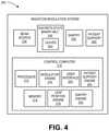
- FIG. 4is a block diagram of an exemplary control computer within a radiation modulation system.
- the control computerwould receive a treatment plan and would control delivery of the plan.
- Radiation modulation system 200includes control computer 210, beam source 230, multileaf collimator (MLC) 240, gantry 250, and patient support 260.
- Control computer 210includes processor 212, memory 214, modulator engine 216, leaf position engine 218, user interface 220, gantry engine 222, and patient support engine 224.
- a control computermay be implemented with several processors, separate computing devices, and otherwise be distributed.
- Processor 212may load and execute programs stored in memory 214.
- the programs stored on memory 214may be executed to perform the functionality described herein, including, gantry control, jaw control, patient support control and other functionality involved in administering a treatment plan.
- Modulator engine 216may control all or a portion of the leaf motion and jaw motion, in order to deliver radiation to a patient in accordance with the treatment plan, may process information regarding the position of a leaf and generate a signal to transmit to a driver to move the leaf to a desired position, or control other components in order to ensure a proper delivery of a treatment plan to a patient. To ensure the desired dose is delivered, modulator engine 216 receives gantry position, leaf position and patient support position information from the gantry engine, leaf position engine and patient support engine, respectively.
- the modulator engine 216may use the position information and control the required intensity modulation for the necessary dosage for a particular set of treatment parameters (e.g., gantry position and/or speed, leaf position, and patient support position and/or speed), in accordance with the treatment plan.
- the modulator engineprovides control sequences for movement of an individual leaf or group of leaves to form a desired aperture or to modulate a beamlet of a shape in accordance with the treatment plan.
- one or more jawsmay also be opened, closed or repositioned in support of beam shaping, intensity modulation or combinations thereof.
- the modulator engineprovides discrete position information for an individual leaf, a group of leaves, and one or more jaws to maintain, or move independently these components to rapidly create a desired beam shape or collimation, enabling treatments with combined volumetric and direct intensity modulation.
- the leaf positioning movements and jaw positioning movementsmay be performed according to desired settings within the treatment plan that correspond to a particular gantry position or speed, patient position or speed or other specific factors for an individual patient's therapy.
- Modulator engine 216may be implemented as software stored in memory 214 and executable by processor 212 or a circuit or logic external to processor 212.
- Leaf position engine 218may control and monitor the movement and position of one or more leaves within magnetically actuated MLC 240.
- Leaf position engine 218may be implemented as logic, a circuit, or software that is stored in memory 214 and loaded and executed by processor 212.
- User interface 220may provide text, graphical content, and other content to be provided through an output mechanism for a user.
- user interface 220provides an interactive graphical interface that provides a user with the current status of the radiation modulation system, treatment status and progress, and other information.
- Gantry engine 222may control and monitor the position of gantry 250. The gantry position may be provided to modulator engine 216, processor 212 and other portions of control computer 210.
- Gantry engine 222may be implemented as logic, a circuit, or software that is stored in memory 214 and loaded and executed by processor 212.
- Beam source 230may provide a therapeutic radiation beam used to treat a patient.
- the beammay be a photon beam generated from a linear accelerator or other particle beam (e.g., proton beam) known in the art to provide treatment to a patient.
- particle beame.g., proton beam
- Magnetically actuated MLC 240includes leaves 242 and may be controlled by control computer 210 to adjust leaf position and provide leaf motion. Additional details of leaf position control and actuation are described below.
- Gantry 250moves about the patient during treatment. The position of gantry 250 may be controlled and monitored by gantry engine 222 of control computer 210. The position of the patient support 260 (and the patient thereon) may be controlled and monitored by the patient support engine 224.
- Magnetically actuated MLCs in accordance with embodiments of the present inventionunlike conventional MLCs of the past (shaping and binary), enable more control for modulating radiation intensity across a beam field for delivering radiation during discrete gantry positions, during gantry rotation/movement, couch motion, target motion or any combination thereof.
- Embodiments of the present inventionpermit moving leaves of a collimator along the continuum of positions between open and closed, such as in conventional shaping MLCs and with a sufficient speed such that leaf sequencing or positioning will not be significantly influenced by any previous or future positions (open or closed for binary collimator) of any individual leaf.
- leaf speedis sufficient such that the mechanics of the MLC do not unduly influence the determination of leaf position at any given time for the delivery of a radiation therapy treatment or fraction.
- This capabilityenables the ability to modify or change apertures non-monotonically, thereby enabling new paradigms of treatment heretofore not enabled by conventional MLCs.
- conventional radiation therapy machineshave used multileaf collimators with relatively slow moving leaves to shape a beam to specific desired shapes, and in this manner create a volumetric intensity modulation.
- FIGS. 5A-5Dshow a leaf in a magnetically actuated collimator, in accordance with embodiments not having all the features of the present invention, where the leaf is in a fully open (state 1, FIG. 5A ) or fully closed position (state 4, FIG. 5D).
- FIGS. 5B and 5Cshow a leaf in a magnetically actuated collimator, in accordance with embodiments not having all the features of the present invention, where the leaf in state 3 ( FIG. 5C ) permitting 20% radiation transmission (i.e., 20% open position) and the leaf in state 2 ( FIG. 5B ) permitting 70% transmission or is in a 70% open position.
- a highly responsive leaf of the discrete-shape binary MLCis one that can achieve a desired position along the continuum of fully opened and fully closed at sufficient speeds such that the mechanics of the MLC do not unduly influence the determination of leaf position at any given time for the delivery of a radiation therapy treatment or fraction.
- the leafcan move to any position in maximum amounts of -y and +y from a starting position of x, at sufficient speeds such that the mechanics of the MLC do not unduly influence the determination of leaf position at any given time for the delivery of a radiation therapy treatment or fraction., which may otherwise be referred to herein as the ability of the leaf or leaves to snap from one position or state to another.
- the limits of conventional shaping MLCs that contribute to the size of +y, -yare leaves driven by rotational motors or leaf screws which limit the speed at which the leaves can be moved.
- the ability of the discrete-shape binary collimator, in accordance with embodiments of the present invention, to snap from one state to another, in addition to the amount of time the collimator remains in one state versus anotherenables an increased ability to modulate radiation intensity over the course of a treatment fraction.
- each leafcan be used to create sub-beamlets or multiple intensity levels. This can be applied to a single-row style construction where each leaf covers one set of beamlets, or an opposing dual bank leaf configuration can be built where beamlets are defined by two or more leaves.
- this configurationhas the volume intensity modulation aspects of traditional MLC's, but with the ability to directly intensity modulate beamlets as with binary collimators.
- each leafcan be quickly sent to any of a number of magnetically actuateds, at sufficient speeds such that the mechanics of the MLC do not unduly influence the determination of leaf position at any given time for the delivery of a radiation therapy treatment or fraction.
- arbitrary 2D patternscan be created very quickly.
- the resulting MLCcan have the speed and simplicity benefits of a binary MLC, but with the flexibility and 2D beam shaping of a conventional shaping MLC hence the name magnetically actuated MLC.
- FIG. 6illustrates exemplary method 500 for delivering radiation therapy utilizing a magnetically actuated MLC, in accordance with an embodiment not having all the features of the present invention.
- method 500begins following initial patient set up (e.g., registering an on-line image (optionally utilizing MVCT) with a planning image, and adjusting the patient support, if needed, to properly align the patient for radiation delivery).
- Fluence map(s)are determined or generated according to the plan (step 510), the sum of which make up a treatment fraction.
- Radiation delivery for a treatment fractionis initiated by receipt of or access to a treatment plan for a patient.
- Initiating radiation deliverymay include determining and setting the initial position of the gantry, the initial leaf position in the multi-leaf collimator, the initial jaws position for primary and secondary collimation (respectively) of the beam, and other initial actions known to those having skill in the art. It will be appreciated by the skilled artisan that this method may be used for other platforms for delivery of radiation therapy, such as a linear accelerator mounted on a six degree of freedom robot (See FIG. 23B for example).
- the fluence map from the treatment plandetermines the collimation sequence, e.g., leaf position and time the leaf is in such position (step 520).
- the fluence mapdictates a series of leaf states necessary to achieve the intensity profile of the fluence map.
- appropriate control signalsare sent by the control computer to leaf actuators to move the leaves in accordance with the treatment plan, i.e., to the desired leaf positions for the desired time to achieve the fluence map.
- a leaf driverreceives the control signals and imparts the commanded leaf movement in accordance with the planned fluence map for that beam, and this process is repeated for each leaf or group of leaves as needed to achieve the fluence map for that beam or gantry angle.
- the treatment fractioncomprises delivery of multiple beams at multiple gantry angles, such that the sum of the delivered fluence maps make up the treatment fraction.
- other treatment system componentsmay be varied (e.g., dynamic gantry motion, couch motion, variable or servo linac output, etc.) in addition to the apertures of the magnetically actuated MLC.
- This descriptionisolates the MLC in order to focus the discussion, and not by way of limiting the invention to any one use or aspect of the MLC , the invention being defined solely by the appended claims.
- step 520it is determined if the state of the collimator (i.e., beam or aperture shape) corresponds to or needs to be changed at any particular point within the delivery of a fluence map. This determination, as will be appreciated by the skilled artisan, will be driven by the treatment plan and will be implemented via leaf positioning accomplished as described herein.
- the position of each leafis determined and then compared to the position from that collimator state (step 530). If a leaf is not in position, a drive signal is provided (step 535) until the desired position is reached. If the leaf is in the desired position (answer to step 530 is 'YES') then next at step 540 determines if the leaf is in the correct position for the correct or desired duration.
- step 545If the leaf has not been positioned for the desired duration, then do not drive the leaf or alternatively send a hold signal to a leaf actuator (step 545). If the leaf has been in position for the desired duration, then the system may move that leaf to another position according to the fluence map or treatment plan.
- step 550the system looks at the next leaf to determine whether it is in position and for the desired duration (according to steps 530-545). After all leaves for a desired collimator state have been completed (answer to step 550 is 'NO') next adjust leaves accordingly to achieve another state (answer to step 555 is 'YES'). If there is not another state (answer to step 555 is 'NO'), then delivery of the fluence map or this portion of the treatment plan is completed.
- step 560If there is another fluence map to deliver at the next gantry angle (answer to step 560 is 'YES') the method returns to step 510 to evaluate/adjust leaf positions accordingly to the steps of method 500. If there is not another treatment fluence map (answer to step 560 is 'NO') then the treatment/fraction ends (step 565).
- a leaf driverreceives control signals at various points throughout the treatment plan to set the leaves of a collimator at the appropriate state for the appropriate amounts of time. It is the treatment plan that, in one form or another, controls the leaf driver and the various states of the collimator.
- the treatment planas described and as will be appreciated by the skilled artisan, will have been developed to take advantage of the ability of the magnetically actuated collimator, in accordance with embodiments of the present invention, to snap from one state to an alternate state in order to deliver a better modulated intensity distribution than if the plan was made for conventional MLCs (either binary or shaping MLCs).
- the treatment plancan utilize the snap movements of the collimator as well as delivering during rotation of the gantry and movement of the patient support to achieve increased abilities to modulate the intensity of the delivery.
- the methodAfter providing control signals to change the state of the discrete-shape binary MLC or if no state change is required, the method loops back for the next point in the delivery of the treatment plan.
- the process of determining the position of each leaf in an MLCis described serially. It is to be appreciated that the steps of the method 500 may be conducted serially or in parallel for one or more leaves or where groups of leaves are moved together.
- leaf, and beamlet control in magnetically actuated MLC embodiments described hereinmay follow sequential or monotonic movements when called for by the treatment plan, but are not so limited. Individual leaf, leaf pair or beamlet control is controlled to a degree that movements are not limited to monotonic shapes, but rather responsive to the next desired state, and not dependent upon where in the continuum the next desired state may be located.
- the MLC controllermay position a leaf to any position at sufficient speeds such that the mechanics of the MLC do not unduly influence the determination of leaf position at any given time for the delivery of a radiation therapy treatment or fraction.
- FIG. 7is an isometric view of an exemplary magnetically actuated MLC having dual leaf banks, one on either side of the area 302 into which radiation is directed for collimation.
- the leavesare driven by electromagnetic action.
- the leavesare supported by a pair of leaf guide modules 300 (one for each leaf bank) driven by components of an electromagnetic drive system in a pair of electromagnetic drive modules 400, one on each side of the collimator for each bank of leaves.
- the present inventioncan be applied to a single bank collimator, but a dual bank is a preferred embodiment.
- a two part support frame 97A, 97B( FIG.
- FIGS. 8-10 and 15-18Details of the electromagnetic drive module 400 are provided with reference to FIGS. 8-10 and 15-18 .
- Details of the leaf guide modules 300are provided with reference to FIGS. 12-14 . Additional details of an exemplary leaf power system are provided with reference to FIGS. 21A-21C and 22 .
- FIG. 8is an isometric end view of one end of electromagnetic drive module 400 of magnetically actuated MLC 240 of FIG. 7 .
- This view of the magnetic drive module 400shows upper and lower openings 415, 425 in end plate 403 for one leaf bank of the preferred dual bank MLC .
- distal ends 346 of drive portion 341 of leaves 340protrude from the upper and lower openings 415, 425.
- Stationary magnets 392are on either side of drive portion 341 of leaf 340, and serve as part of the leaf power system for moving the leaves, as discussed more thoroughly below.
- upper leaf encoder 330interacting with upper encoder reader 360 and upper flex circuit 460 (lower leaf encoder, lower encoder reader and lower flex circuit not shown).
- width W of drive portion 341is smaller than width W' of blocking portion 342 to facilitate packing a plurality of leaves 340 adjacent to each other while having stationary magnets 392 ( FIG. 10 ) on either side of drive portion 341 for each leaf.
- stationary magnets 392 on either side of drive portion 341are horizontally offset by approximately the thickness of one leaf from the stationary magnets 392 on either side of drive portion 341 ( FIG. 9 ).
- the geometry and placement of leaves 340 in this embodimentfacilitates efficient packing of leaves 340 adjacent to each other with magnets 392 on either side of drive portion 341.
- the skilled artisanwill appreciate that other geometries are available to pack the leaves adjacent to one another and remain within the scope of the present invention.
- Embodiments (not necessarily having all the features of the present invention) of the design and operation of the leaf and encoderis discussed in more detail below with regard to FIGS. 15-18 and 20 .
- FIG. 9is an enlarged view of distal ends 346 of drive portion 341 of leaves 340 protruding from upper opening 415 of the electromagnetic drive module 400 of FIG. 8 , also showing a portion of the flex circuit 460 and encoder reader 360.
- the plurality of leaf drive portions 341are shown in section view. Additional details of the components of a leaf 340 including drive portion 341 are shown and described more fully below in FIGS. 15-18 and 20 .
- the view of FIG. 9illustrates the arrangement of the leaf drive section upper and lower portions 341A, 341B alongside stationary magnets 392. The lateral thickness of sections 341A, 341B are used to maintain the leaf coil 350/windings 348 in the desired relationship to magnets 392, as discussed more thoroughly below.
- FIG. 11is a top down view of the central portion 302 of the magnetically actuated MLC 240 of FIG. 7 showing inner leaf guides 301, aperture 1050 and 14 leaf pairs (1010-1039) in various positions between leaf guide inner supports 301. While 14 leaf pairs are shown more or fewer leaf pairs may be provided according to the design requirements of a particular system. In one preferred embodiment, there are 64 leaf pairs, in another embodiment there are 96 leaf pairs and in still another embodiment there are 32 leaf pairs. As will be apparent, radiation is collimated through this section 302 of the collimator.
- each leafis positioned in a particular position to define a particular aperture or shape 1050 through which radiation may pass, also referred to herein as a state.
- Leaf pairs 1010 and 1011 through 1038 and 1039are controlled using the control schemes and drivers described herein to enable simultaneous volume and intensity modulation.
- one or more controllable jawsare used to provide primary collimation of the beam, defined by the inner edges 301i and the frames 97A, 97B (i.e., the jaws will block the open space between support frame B and leaf pair 1010/1011 and between support frame A and leaf pair 1038/1039). Additionally or alternatively, the one or more pairs of jaws may be adjusted to reduce the size of the primary collimated beam to smaller than the frame size.
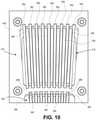
- FIG. 12is a perspective view of an exemplary leaf guide module 300 of a magnetically actuated MLC 240.
- the leaf guide module 300has opening 321 sized to receive a plurality of leaves 340.
- the size of opening 321varies based on the number of leaves used in a particular MLC design.
- a plurality of guide channels 322is provided on the upper and lower surfaces of the guide about the opening.
- a portion of the leaf 340is adapted for sliding arrangement into the plurality of guide channels 322.
- primarily blocking portion 342sits within guide channel 322, though driving portion 341 may also occupy some or all of the length of guide channel 322 as a leaf is moved into and out of a desired position.
- FIG. 12is a perspective view of an exemplary leaf guide module 300 of a magnetically actuated MLC 240.
- the leaf guide module 300has opening 321 sized to receive a plurality of leaves 340.
- the size of opening 321varies based on the number of leaves used in
- FIG. 13Ais an end on view of leaf guide module 300 in FIG. 12 showing an end on view of the blocking portion 342 of seven leaves 340 within their respective guide channels 322.
- the leaves 340will have a tongue and groove construction ( FIG. 13B ) to prevent leakage between adjacent leaves, as shown by reference number 341.
- edge portions 342a, 342b of the leaf blocking portion 342adapted and configured for sliding within the guide channels 322.
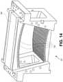
- FIG. 14is a perspective view of an exemplary curved leaf guide module 300.
- opening 321has an arched shape in contrast to the substantially vertical alignment of the leaf guide embodiment of FIG. 12 .
- a plurality of leaf guide channels 322is provided in the leaf guide on the upper and lower portions about opening 321.
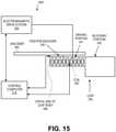
- FIG. 15is a diagram of an exemplary control system 401 for a magnetically actuated MLC 240.
- the leaf driveris an electromagnetic drive system 320.
- This figurepresents an exemplary leaf 340 of an electromagnetic multileaf collimator 200.
- Control system 401may include control computer 210, driver 320, leaf position encoder 330 and leaf 340.
- additional encoder 360may also be used to provide two forms of positional feedback, depending upon the specific encoder or positioning system configuration.
- Leaf 340has a driving portion 341 and a blocking portion 342.
- Blocking portion 342is shaped, adapted and configured for blocking the therapeutic beam, made of radio opaque material, preferably tungsten or tungsten alloy and is about 20-70 mm wide.
- Leaf driving portion 341, attached to blocking portion 342,provides structural support for blocking portion 342 as well as windings or coil 350 and any additional components needed or desired.
- width W of blocking portion 342is larger than width W' of driving portion to facilitate efficient packing of the leaves in the MLC.
- leaf driving portion 341includes components used for an electromagnetic driver ( coils).
- the size, number and orientation of coils 350will vary depending upon other factors such as the size, placement and the strength of stationary magnets 392 used in the embodiment of the magnetically actuated MLC, the dimensions available for the components and other factors. As presently envisioned, the number of coils 350 may vary, but the number of coils 350 exposed to electromagnetic drive module 400 and stationary magnets 392 remain approximately constant in order to apply a uniform force to driving portion 341.
- leaf 340 in a magnetically actuated MLC configurationmay be modified depending upon the requirements of electromagnetic driver 320.
- leaf 340may include coil 350 made from windings 348 ( FIG. 18 ).
- Control computer 210receives signals from encoder 360/330 depending upon the specific position system used. In some embodiments, the signals may indicate position data captured by position encoder 330. Control computer 210 processes the received signals and determines whether leaf 340 is at a desired position. If the position of leaf 340 needs to be changed, control computer 210 signals driver 320 to change the position of the leaf. Control computer 210 may also provide control signals to drive a magnetic field generated by coil 350.
- control computer 210may control the strength, activate or deactivate the magnetic field of coil 350 by adjusting current flowing through the coils. Additional details of magnetic drive and control are described herein with regard to FIGS. 20 and 21A-21C .
- the position encoder 330 on the leaf and the guide mounted encoder 360are both fed into the control loop to more precisely control the motion of the leaf position.
- the position encoder 330 on the leaf and the guide mounted encoder 360can be compared against each other as a form of secondary positional verification.
- the controllercould use current torque applied as a control input for leaf position control.
- driver 320may receive a signal from control computer 210 to provide a current to coils 350 from electrical drive connector 605 ( FIGS. 7 and 15 ).
- the currentresults in a magnetic field generated by coils 350.
- the magnetic field generated by coils 350acts in concert with the permanent magnets 392 on either side of driving portion 341 within the magnetic drive module 400 to produce controlled leaf movement.
- Permanent magnets 392may be arranged parallel to the coils 350. In some embodiments, permanent magnet 392 in magnetic drive module 400 may be at least twice the length of the coils 350 so that the magnet may apply relatively constant driving force to driving portion 341.
- the number of coils adjacent to permanent magnets 392preferably remains approximately constant so as to apply an approximately constant force to driving portion 341 for any given current and magnetic strength.
- Coils 350may extend at least as long as a leaf so that it is controllable to the full leaf width.
- the coil length or the number of coilsis influenced by the amount of desired leaf travel and desired force to move the leaf.
- the depicted embodimentshows a preferred nine coils, but the number of coils can be selected based on particular needs, for example three or six coils may be used. The skilled artisan will consider many factors, the power input required to move the leaves, and heat dissipation to name two, when selecting the number of coils and the length of the permanent magnets.
- a first magnetic fieldmay be generated by a permanent magnet made of a material such as neodymium or other high density strong permanent magnet.
- the strength of the magnetic fields from the coils and the permanent magnetsmay be constant as the leaf is driven through the guides.
- the coilsare potted to the leaf with a material selected for its thermal, mechanical and environmental properties. Table 1 below provides some estimated specifications for 3, 6 and 9 coil embodiments of a leaf design, where the 9 leaf embodiment is estimated to move at least approximately 1 m/s with an acceleration of approximately 80m/s 2 (a trapezoidal acceleration rate with a peak velocity of approximately 2 m/s in approximately 0.25 ms).
- FIG. 16is a side view of an exemplary leaf.
- a leaf 340may include driving portion 341 and blocking portion 342.
- Driving portion 341includes proximal end connected to blocking portion 342 and distal portion 346.
- Driving portioncan have any suitable dimensions, but preferably is approximately 135mm x 35mm.
- driving portion 341may also include a plurality of windings 348 to form coils 350. When current is applied to these coils, for example by electrical drive connector 605 ( FIGS. 7 and 22 ), the interaction between these coils and the flux density created by the stationary magnets produces a force in the direction of motion desired.
- Coils 350may be constructed from a conductive material, such as AWG copper wire. The diameter of the wire and the number of turns may be based on the amount of desired torque among other properties, for example, as will be appreciated by the skilled artisan.
- Blocking portion 342is sized and shaped to move within guide structure 300 (see e.g., FIGS. 12 and 13A ).
- blocking portion 342may be a composite structure made from different materials.
- blocking portions 342include first portion 370 and second portion 380.
- First portion 370is preferably made from a radio opaque material such as tungsten or alloy thereof and forms all or nearly all of blocking portion 342.
- Second portion 380(the portion not intended to block radiation, but rather move through the leaf guiding structure or motor support areas) is preferably made from a lighter or less dense material to minimize leaf mass (including without limitation aluminum or stainless steel), reduce friction and facilitate ease of leaf acceleration and deceleration.
- FIG. 17is a perspective view of an exemplary pair of leaves 340 as would be oriented in the magnetic drive and leaf guide structures of the MLC of FIG. 12 .
- Blocking portion 342is sized and shaped to move within guide structure 300.
- Guide rails 342A and 342B on each side of the blocking portion 342are adapted and configured for sliding cooperation with channels 322 in leaf guide 300.
- FIG. 18is a cross-sectional view of leaf 340 having a tapered cross section resulting in varying thicknesses of blocking portion 342 and driving portion 341 , as it is required for the present invention .
- one coil 350 made of coil windings 348is shown within driving section 341. Due to the tapered cross section shape of the leaf, windings 348 have the same number of turns but are arranged to accommodate the available space.
- FIG. 19illustrates an exemplary discrete binary MLC leaf arrangement.
- a collimated field 1040 having a center line 1030is provided by a pair of jaws or other collimator device (see FIG. 3 ).
- two leavesform a complementary leaf pair for shaping and modulation of the collimated field 1040.
- leaves 1010 and 1011are one leaf pair.
- Leaves 1018, 1019are another and leaves 1024, 1025 still another.
- Each leaf in each pairmay be positioned anywhere within field 1040.
- the inner edges of each leaf within a leaf pairface each other and may create an opening, the collection of openings formed by each leaf pair forms aperture 1050.
- Aperture 1050corresponds to an aperture of FIG. 11 previously described and is set according to a treatment plan.
- an aperture 1050is determined prior to administering radiation therapy to a patient in the treatment planning process, and occurs at a particular point during delivery of the treatment plan.
- Aperture 1050may change according to a number of factors, such as for example, the three dimensional shape of the treatment area, intensity modulation, fluence, and beamlets within a treatment volume as described above.
- Embodiments of the highly responsive MLCs described hereinachieve volume and intensity modulation alone or in simultaneous combination by providing snap state control.
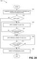
- FIG. 20is an exemplary method for using an electromagnetically driven discrete binary MLC (i.e., eMLC).
- the MLCis controlled as described above in the method 500 of FIG. 6 with appropriate electromagnetic drive signals used to move or hold each leaf in position depending upon the specific implementation of an electromagnetic drive system.
- the method steps described in FIG. 6 at steps 530, 535, 540 and 545are thus met by providing drive, control and hold signals as needed to control leaf movement.
- FIG. 20illustrates an exemplary method for delivering radiation therapy utilizing an electromagnetic multileaf collimator (eMLC).
- Radiation treatment for delivering a dose for a current treatment planis initiated in accordance with a treatment plan.
- the state of the eMLCis obtained from the treatment plan. It is determined whether the present state of the eMLC matches the desired state. If yes, the treatment proceeds until the next point within the treatment plan where the same question is asked again. If the present state of the eMLC is not the same as the desired or planned state, then appropriate signals are sent to controller to snap the appropriate leaves to a different position to achieve the desired state.
- the magnetic field control signalsare initially sent by control computer 210 to driver 320.
- Driver 320receives the control signals and provides a current to one or more coils to create a magnetic field in the particular coils of the involved leaf.
- the magnetic field generated by the coilscooperates with a magnetic field of the permanent magnets proximate to the coils and leafs to move the leaves in a desired direction.
- the processrepeats for leaves in the MLC.
- FIG. 20illustrates an exemplary method 1200 for positioning a leaf using the electromagnetic control system 401 described herein.
- the steps shownare part of an overall MLC and treatment plan as described above in FIG. 6 and method 500.
- the method 1200corresponds to decisions made in method 500 to move a leaf using an electromagnetic MLC control scheme (see FIG. 6 ).
- a desired leaf positionis determined based on, for example and without limitation, gantry position, patient position, or desired fluence map according to a treatment plan as in steps 510, 520 above.
- the current leaf position and desired leaf position for field shapingare compared at step 1220.
- the comparisonis used to answer the question "leaf in position?" asked in step 530 of the method 500 (see FIG. 6 ).
- the current leaf position for each leafmay be determined by signals provided by a flex circuit and encoder read head to control computer ( FIGS. 8 and 15 , for example).
- the desired location for each leafmay be determined as discussed with respect to steps 510, 520 above.
- a determinationis made at step 1230 as to whether a leaf should be moved. A leaf is moved if the current position of the leaf does not satisfy the desired position of the leaf. If the leaf does not need to be moved, the process continues to step 1280 where remaining leaves are moved if needed.
- a currentis applied to the leaf coil at step 1240.
- the currentis applied by driver 320 of FIG. 15 which receives control signals from control computer 210 (see FIGS. 3 and 4 ).
- the current applied to the leafmay vary. At first, the current may ramp up to a level required to initiate movement of the leaf and overcome friction between the leaf and any object in contact with the leaf while at rest.
- the leaf positionmay be detected by a flex circuit and encoder read head.
- a leaf position "near the desired position"may be a position at which a braking current may be applied to slow down movement of the leaf such that it will stop at the desired position, preferably within approximately ⁇ 10 microns of the desired position.
- a braking currentmay comprise reducing current to the coils thereby reducing the magnetic field of the coils which will reduce the amount of force exerted on the driving portion, and friction will act to reduce the leaf speed.
- the current to the coilsmay be reversed in one or more of the coils to create an opposite magnetic field which acting in cooperation with the permanent magnetic field will act as a braking force in combination with friction.
- a physical braking forcein addition to normal friction from the guides could be applied.
- the skilled artisanwill appreciate that many different forms of a braking force could be applied without deviating from the scope of the present invention, and that these are but a few examples.
- the point at which a braking force is appliedwill depend on the system configuration and that of the control system dynamics, and if the detected position is not at the position where braking is to be applied, the method returns to step 1240. If the detected position is near the desired braking position, a braking current may be applied to the leaf coil at step 1260 such that the leaf will stop motion within approximately ⁇ 10 microns of the desired position.
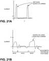
- FIGS. 21A, 21B and 21Cillustrate representative drive current schemes for various leaf positioning scenarios used in an electromagnetically actuated multi-leaf collimator.
- FIG. 21Aillustrates a current pulse for a high power burst mode.
- This control modewill be described in conjunction with the leaf movement methods of FIG. 20 .
- the leaf control systemis driven so as to move a leaf from one position to another as rapidly as possible.
- the systemmay apply maximum drive current in a short pulse based on time rather than position.
- the leaf drive systemmay operate in an open loop scheme driving current without regard to input from positions sensors.
- these high current pulsesmay be considered part of either driving, braking or holding a leaf of an eMLC.
- the drive control signalsmove a leaf a rapidly as possible.
- this drive current profilealso illustrates how the system is able to provide a peak drive current that is many times greater than the mean drive current (x) .
- the peak drive current in the leaf control systemis 50 times, 75 times or even 100 times the mean drive current x.
- conventional systemsoperate with a peak current that is only about 2 times the mean peak current.
- FIG. 21Billustrates an exemplary drive control scheme for precise movement during leaf positioning that will be described in conjunction with the leaf movement methods of FIG. 20 .
- This control schememay be used to achieve the positioning and braking described in FIG. 20 .
- the process of applying a current to a leaf(step 1240) will vary as the position feedback system indicates the leaf is in motion, at the desired movement (e.g., accelerating, steady state velocity, decelerating) or holding a desired position (i.e., no movement).
- the current demands for a leaf in these different statesare different.
- the leaf control systemprovides a hold current to maintain the leaf position.
- the "hold phase" current levelwould likely be different from that needed to accelerate or maintain the velocity of a leaf.
- This processmay include many cycles of steps 1230, 1240 and 1250 on a very small scale depending upon the precision of the positioning system and the desired degree of positioning accuracy during the hold step.
- FIG. 21Cillustrates the use of the drive currents as a secondary position sensor.
- This figureillustrates the phase current drive (lower graph) used as a predictor for position (upper graph).
- phase current used to drive a leafmay be checked within the position control system as a secondary positioning indicator to the leaf position indicator (i.e., leaf position encoders or other positioning system used by the system - see FIGS. 13 and 22 ).
- FIG. 22is an isometric view of an exemplary leaf driver circuit positioned between the magnet guide module 400 and the leaf support module 303 of FIG. 7 .
- the power drive module 600includes a drive connector 605 with a flex connector 610 extending into sliding electrical contact with a power connector or power pick up 615 on a leaf 340.
- the power pick up 615provides current to the windings 348 of the one or more coils 350 via electrical connectors on the leaf driving portion 341.
- Powermay be provided to the coils by a brushed type connection or a flexible circuit with either direct wiring from the flex to the coils or with some intermediate connector, which will be appreciated by the skilled artisan.
- embodiments of the highly responsive leaf control systemare adapted and configured to provide individual leaf positioning solutions to provide both IMRT and, if needed, VMRT position solutions alone or in combination on a leaf by leaf basis.
- the magnetically actuated MLCin accordance with embodiments of the present invention (the eMLC being one such embodiment), enables new treatment approaches with improved conformality and speed of delivery.
- FIG. 23Aillustrates a radiation therapy treatment system 10 that can provide radiation therapy to a patient 14 utilizing MLCs in accordance with embodiments of the present invention.
- the radiation therapy treatment system 10includes a gantry 18.
- Gantry 18can support radiation module 22, which can include radiation source 24 and linear accelerator 26 operable to generate beam 30 of radiation.
- gantry 18 shown in the drawingsis a ring gantry, i.e., it extends through a full 360° arc to create a complete ring or circle, other types of mounting arrangements may also be employed.
- a non-ring-shaped gantrysuch as a C-type, partial ring gantry, or robotic arm could be used.
- radiation source 24may travel in a path that does not follow the shape of gantry 18.
- radiation source 24may travel in a non-circular path even though the illustrated gantry 18 is generally circular-shaped.
- the radiation therapy treatmentcan include photon-based radiation therapy, brachytherapy, electron beam therapy, proton, neutron, or particle therapy, or other types of treatment therapy.
- Radiation module 22can also include modulation system 200 operable to modify or modulate radiation beam 30. Modulation device 200 provides the modulation of the radiation beam 30 and directs radiation beam 30 toward patient 14. Specifically, radiation beam 30 is directed toward a portion of the patient.
- the radiation modulation systemin accordance with embodiments not necessarily having all the features of the present invention is described in more detail above.
- Modulation device 34can include collimation device 42, as illustrated in FIG. 3 and FIGS. 7-19 .
- Collimation device 42includes a set of jaws 46 that alone or in combination with the primary collimator defines and adjusts the size of aperture 50 through which radiation beam 30 may pass to provide primary collimation.
- Jaws 46include upper jaw 54 and lower jaw 58. Upper jaw 54 and lower jaw 58 are moveable to adjust the size of aperture 50.
- FIG. 23Billustrates an embodiment of a radiation system 700 having a radiation source and modulation device mounted on a robotic arm.
- the radiation system 700is similar to the radiation system 10 described herein.
- FIG. 23Bincludes a radiation module 720 similar to radiation module 22 including, for example, a linear accelerator and an embodiment of the modulation device is mounted on a robotic arm 746.
- the robotic arm 746moves with 6 axes of motion under control of the computer controller 74 to position the radiation source 720 freely and in 6 degrees of freedom about the patient's body, up or down, longitudinally along the patient or laterally along the patient.
- a pair of in room diagnostic imaging devices 730, 732that direct one or more imaging beams 726, 732 towards the patient 14 and appropriate image receivers 734, 736.
- computer 74includes an operating system for running various software programs and/or a communications application.
- computer 74can include software program(s) 90 that operates to communicate with radiation therapy treatment system 10.
- Computer 74can include typical hardware such as a processor, I/O interfaces, and storage devices or memory, keyboard, mouse, monitor.
- Computer 74can be networked with other computers and radiation therapy treatment systems 10. The other computers may include additional and/or different computer programs and software and are not required to be identical to the computer 74, described herein.
- Computer(s) 74 and radiation therapy treatment system 10can communicate with network 94 ( FIG. 24 ).
- Computer(s) 74 and radiation therapy treatment system 10can also communicate with database(s) 98 and server(s) 102.
- DICOMdigital imaging and communications in medicine
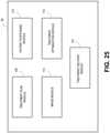
- FIG. 25is a schematic illustration of software program 90.
- Software program 90includes a plurality of modules that communicate with one another to perform functions of the radiation therapy treatment process.
- the various modulesare adapted to communicate with one another to plan and deliver radiation therapy to patient 14.
- Software program 90includes treatment plan module 106 operable to generate a treatment plan for patient 14 based on data input to system 10 by medical personnel, as previously described.
- the dataincludes one or more images (e.g., planning images and/or pre-treatment images) of at least a portion of patient 14.
- Treatment plan module 106separates the treatment into a plurality of fractions and determines the radiation dose for each fraction or treatment based on the input from medical personnel.
- Treatment plan module 106also determines the expected radiation dose for target 38 and surrounding critical structures based on contours drawn by the planner. Multiple targets 38 may be present and included in the same treatment plan.
- Software program 90also includes patient positioning module 110 operable to position and align patient 14 with respect to the isocenter of the gantry 18 or other reference for a particular treatment fraction based on a registration of an on-line CT image (preferably an MVCT image) with the planning CT image, commonly referred to as patient setup.
- patient setuppreferably an MVCT image
- the image registrationprovides offsets to the patient positioning module 110, which instructs drive system 86 to move couch 82 to align the patient relative to the treatment delivery system prior to treatment delivery, alternatively patient 14 can be manually moved to a new position or couch 82 can be manually adjusted.
- Patient positioning module 110may also control movement of couch 82 during treatment in accordance with the treatment plan. In a robotically mounted system the offsets may be used to direct the robot to deliver radiation to the desired location within the patient, as is well known by the skilled artisan.
- Software program 90can also include image module 114 operable to acquire the on-line images of patient 14.
- Image module 114can instruct the on-board image device, such as a CT imaging device, to acquire images of patient 14 before treatment commences, during treatment, and after treatment according to desired protocols.
- Other imaging devicesmay be used to acquire pre-treatment images of patient 14, such as non-quantitative CT, MRI, PET, SPECT, ultrasound, transmission imaging, fluoroscopy, RF-based localization, and the like.
- the acquired imagescan be used for registration of patient 14.
- Software program 90can also include treatment plan module 106 and treatment optimization module 118; preferably these two modules are included as a software product, the output of which is an optimized treatment plan for a patient that is ultimately approved by clinical professionals and provides direction to the treatment delivery system for delivering radiation to a patient.
- Treatment delivery module 122uses the treatment plan as an input to control and guide delivery of radiation to the patient.
- the treatment planwill include, but is not limited to, providing leaf positions, jaw positions, gantry angles and angular speed, and couch speed.
- radiation therapy treatment system 10can also include detector 78, e.g., a kilovoltage or a megavoltage detector, operable to receive radiation beam 30.
- Linear accelerator 26 and detector 78can also operate as a computed tomography (CT) system to generate CT images of patient 14.
- CTcomputed tomography
- Linear accelerator 26emits radiation beam 30 toward target 38 in patient 14.
- Target 38 and surrounding tissuesabsorb or attenuate some of the radiation.
- Detector 78detects or measures the amount of radiation absorbed from different angles as linear accelerator 26 rotates around, which information is processed or reconstructed to generate images, preferably 3D CT images as is known in the art, of the patient's body tissues and organs.
- the imagescan also illustrate bone, soft tissues, and blood vessels.
- the CT imagescan be acquired with linear accelerator 26 delivering megavoltage energies or kilovoltage energies.
- Alternative gantry systemsmay permit acquisition of cone beam CT images.
- other sources of diagnostic x-ray energiestypically Kv energies
- Kv energiescan be located on the gantry and be separate from the Mv therapeutic source.
- Radiation therapy treatment system 10can also include a patient support, such as couch 82 (illustrated in FIG. 23A ), which supports patient 14.
- Couch 82moves along at least one axis 84 in the x, y, or z directions, but may also include the ability to control pitch, roll and yaw.
- the control systemscan control couch velocity in accordance with the treatment plan and to achieve the desired intensity modulation.
- Patient support systemsare well known in art and will not be further described here.
Landscapes
- Health & Medical Sciences (AREA)
- Engineering & Computer Science (AREA)
- Biomedical Technology (AREA)
- Physics & Mathematics (AREA)
- General Health & Medical Sciences (AREA)
- Radiology & Medical Imaging (AREA)
- Life Sciences & Earth Sciences (AREA)
- Animal Behavior & Ethology (AREA)
- Nuclear Medicine, Radiotherapy & Molecular Imaging (AREA)
- Public Health (AREA)
- Veterinary Medicine (AREA)
- Pathology (AREA)
- Spectroscopy & Molecular Physics (AREA)
- General Engineering & Computer Science (AREA)
- High Energy & Nuclear Physics (AREA)
- Radiation-Therapy Devices (AREA)
Description
- This application is a non-provisional of and claims priority to
U.S. Provisional Application No. 61/769,549, filed on February 26, 2013 - The present invention generally relates to radiation therapy. In various respects, the invention is directed to a highly responsive multileaf collimator, and method of use to provide radiation therapy utilizing beam shaping, intensity modulation and combinations thereof including simultaneous beam shaping and intensity modulation of therapeutic beams.
- Intensity modulated radiotherapy (commonly referred to as IMRT) is a generic term for a number of radiotherapy techniques that, essentially, vary the beam intensity that is directed at the patient. That variation can be spatial, temporal, or both.
- In radiation therapy the terms dose, fluence and intensity are sometimes used interchangeably and confusingly. For the purposes of this description and this application these terms are used as follows. Fluence is the number of photons or x-rays that crosses a unit of area perpendicular to a radiation beam. Fluence rate is the fluence per unit time. Intensity is the energy that crosses a unit area per unit time. Fluence and intensity are independent of what occurs in a patient, and more specifically are not dose. Dose is the amount of energy absorbed by tissue by virtue of radiation impacting the tissue. Radiation dose is measured in units of gray (Gy), where each Gy corresponds to a fixed amount of energy absorbed in a unit mass of tissue (e.g., 1 joule/kg). Dose is not the same as fluence, but increases/decreases as fluence increases/decreases.
- In radiation therapy delivery, the beam aperture is commonly set by a multi-leaf collimator (MLC). One such method of using the MLC is to create one or more patterns that shape the radiation. A single shape that matches a target is commonly referred to as a conformal delivery. For more complicated dose distributions IMRT can be utilized. In IMRT, rather than having the MLC shape the incident radiation to match a certain outline, the MLC is instead used to create an array of beam shapes that create a desired intensity modulation and desired 3D dose distribution.
FIG. 1 illustrates an isometric view of a conventional shaping-MLC 31 (such as those used on Varian radiation therapy systems) passing a beam to a target in a patient. Twobanks leaf 37 may be positioned continuously across the radiation field. The two banks of leaves are positioned so as to collimate thebeam 30 in the desired shape. Eachleaf 37 typically may travel beyond the midpoint of the collimator in order to provide flexibility when achieving the desired collimation. The configuration illustrates fully open (41), partially open (43) and closed (45) leaf states.- In an example of radiation therapy, each gantry angle has one beam associated with that particular gantry angle, which
beam 30 is then collimated into multiple shapes by an MLC.Treatment beam 30 passes through theshaped aperture 47 formed by theleaves 37. The resulting collimated beam continues onto atarget 14 within thepatient 38.FIG. 1 also illustrates how the treatment beam may be visualized or conceptualized as manydifferent beamlets 49.Leaves 37 of conventional shaping-MLC 31 are moved into various positions to achieve desired shapes or apertures for specified periods of time to achievefluence map 51 for that particular beam. Modulation of the conceptualized beamlets occurs by sequentially and monotonically moving the leaves into desired positions to achieve desired shapes or appertures such that the time a conceptualized beamlet is exposed controls the intensity of that beamlet. Monotonic, as used in this application and related to radiation therapy, means an ordered sequence of apertures where the sequence is dictated by a continuum from one aperture to a subsequent aperture or where individual leaves increment in one direction during a given series of apertures. In other words, a sequence of apertures would be dictated by mechanical limitations of the MLC, not so much by what may achieve the more optimal treatment delivery; a sequence would go fromaperture 1, then 2 then 3 and so on, and not from 1 to 3 then to 5 then back to 2. Rather than use a single conformal shape, the MLC delivers a sequence of shapes. The net amount of radiation received at any given gantry position is based upon the extent to which the different shapes permit the passage or blockage of radiation. As seen inFIG. 1 , the shape ofMLC 31 shown does not directly correspond to the beamlet intensities of thefluence map 51. As will be appreciated, the depicted fluence map shows the accumulation of intensities for multiple shapes the MLC has taken for that particular gantry angle. A common limitation of the conventional shaping MLC is that the leaves defining the shapes move relatively slowly. Using large numbers of shapes, or shapes that require large leaf motions, can result in longer patient treatments. Likewise, the speed of the leaves can limit the ability of conventional shaping-MLC's to deliver time-sensitive treatments, such as utilizing synchronized motion of delivery components (e.g., gantry, couch, x-ray energy etc.). - A conventional
binary MLC 61 is shown inFIG. 2 . Thebinary MLC 61 has a plurality ofleaves 63 arranged in twobanks FIG. 2 , the leaves may work in concert to be both open (A), both closed (B) or where only one leaf is open/closed (C). - Binary MLCs are used in TomoTherapy's Hi-Art® radiation therapy system and the North American Scientific treatment system. In the conventional binary-MLC treatment system the patient is moved past the rotating radiation source to deliver a helical treatment to the patient using the dual bank binary collimator. Alternatively, the patient is indexed for treatment of another subsequent two slices by the dual bank binary collimator, as is done by the North American Scientific system. Leaves of the dual bank binary collimator move with sufficient speed such that leaf sequencing or positioning will not be significantly influenced by any previous or future positions (open or closed for a binary collimator) of any individual leaf. Stated another way, leaf speed is sufficient such that the mechanics of the MLC do not unduly influence the determination of leaf position at any given time for the delivery of a radiation therapy treatment or fraction. Thus, and in contrast to the conventional shaping-MLC, each leaf defines a beamlet that does not require conceptualization by the planning software, i.e., the amount of time a leaf is open directly controls the intensity for that beamlet.
- For both conventional MLCs (shaping and binary), each beamlet has a fluence and all the fluences combined form a fluence map for the beam. The fluence maps for each gantry angle or for all the beams are combined and optimized into the treatment plan. The example of the conventional shaping MLC has been provided to illustrate the underlying concepts of volumetric intensity modulation using the shaping MLC and that of the binary MLC to illustrate the underlying concepts of direct intensity modulation at discrete gantry angles. More complicated treatment plans and delivery can include gantry motion, couch motion, varying gantry speed, varying MU, etc. in order to provide more sophisticated and theoretically better dose conformation in less time per fraction. It is the treatment plan, via delivery software, that governs the operation of the treatment delivery device. The physical capabilities of the delivery system (gantry, linear accelerator, MLC, couch, etc.) limits or constrains the treatment planning software in the type of plan it can create and optimize for delivery by the delivery system.
- Treatment planning systems and software (collectively referred to as planning system) are not the focus of this application, but, and as will be appreciated, are integral for treating a patient with radiation. Radiation therapy treatments are governed by a treatment plan, typically generated by a physician or physicist (alone or collectively a "planner") using the planning system. The planner will typically use a diagnostic 3D image (typically CT, although combinations of any PET, CT, MR maybe used) and define or contour the target structure and any nearby critical structures or organs at risk (OAR). The planner then determines the amounts of radiation for delivery to the target structure and the amount of radiation that will be allowed to the OAR. The treatment planning software, using inverse planning and the physical capabilities of the delivery device will generate a treatment plan. The planner then evaluates the plan to determine if it meets the clinical objectives, and if so will approve the plan for delivery to the patient. Delivery of the plan occurs in multiple treatment sessions or fractions.
- Conventional MLCs and the treatment paradigms resulting from them have provided steadily advancing and more sophisticated conformal radiation therapy treatments. However, there remains a need for more advanced shaping and modulation of the therapeutic beams, thereby enabling treatment planning software to develop and enable delivery of even more sophisticated plans. As seen by the above summary of radiation therapy techniques, one key component for delivery of radiation therapy is the collimator. While multi-leaf collimators exist, the speed and control of an individual leaf or group of leaves is insufficient to achieve more advanced simultaneous shaping and modulating beam patterns. What is needed are improved multileaf collimator designs, responsive enough to meet the speed and position control requirements of more advanced radiation treatment plans, thereby enabling new treatment paradigms.
US6188748B1 discloses a contour collimator for radiotherapy, wherein each drive is preferably formed by a linearly acting electric linear motor.- Also
WO2008/106500A1 ,JP2007319440A JP2006311882A CN102755696A andCN2445754Y disclose different types of multi-leaf collimators with linear motors. US6104108A discloses a wedge magnet array for a linear motor andUS5440183A discloses an electromagnetic apparatus for producing linear motion.US394452A discloses a verification system for radiation therapy, wherein actuator have internal armatures received within solenoid electromagnets.US2005/063516A1 discloses a multi-leaf collimator and medical system including accelerator.- The invention is defined by the present independent claims.
- Preferred embodiments are provided in the dependent claims.
- A better understanding of the features and advantages of the present invention will be obtained by reference to the following detailed description that sets forth illustrative embodiments, in which the principles of the invention are utilized, and the accompanying drawings of which:
FIG. 1 illustrates a conventional shaping MLC being used to provide a representative dose to a target in a patient.FIG. 2 is a bottom up view of a conventional binary MLC.FIG. 3 is a perspective view of a discrete binary multi-leaf collimator that can be used in the radiation therapy treatment system illustrated inFIG. 3 .FIG. 4 is a block diagram of an exemplary computer control scheme.FIGS. 5A-5D illustrate the movement of a representative leaf in open, closed and partially open states as a result of operation as part of a discrete binary multi-leaf collimator.FIG. 6 is a flow chart of a fluence and leaf control scheme for discrete binary multileaf collimator.FIG. 7 is an isometric view of an exemplary highly responsive MLC.FIG. 8 is an isometric end view of one end of a magnetic drive module of the MLC ofFIG. 7 .FIG. 9 is a close up an enlarged perspective view of the first leaf bank in the magnet guide module with a portion of the flex circuit and reader removed.FIG. 10 is an end on view of the magnet guide module with a cover removed to show the arrangement of the stationary magnets between leaves.FIG. 11 is a top down view of the inner leaf guides and opening ofFIG. 7 .FIG. 12 is a perspective view of an exemplary straight leaf guide.FIGS. 13A and13B illustrate an end on view of the guide inFIG. 11 showing an end on view of the blocking portion of leaves within their respective guide channels.FIG. 14 is a perspective view of an exemplary curved leaf guide.FIG. 15 is a diagram of an exemplary control system for an exemplary leaf in an electromagnetically controlled highly responsive multi-leaf collimator.FIG. 16 is a side view of an exemplary leaf.FIG. 17 is a perspective view of an exemplary leaf pair as positioned within an exemplary MLC.FIG. 18 is a cross-sectional view of coil windings in an exemplary leaf and is the only figure showing a leaf of a MLC according to the invention;FIG. 19 illustrates an exemplary leaf arrangement for a discrete binary MLC.FIG. 20 illustrates an exemplary method for positioning a leaf using an electromagnetically controlled discrete binary MLC.FIGS. 21A, 21B and21C illustrate representative drive current schemes for various leaf positioning scenarios used in an electromagnetically actuated multi-leaf collimator.FIG. 22 is an isometric view of a leaf power drive as shown inFIG. 7 .FIGS. 23A and23B illustrate a perspective view of a gantry based radiation therapy treatment system and robotic based radiation therapy system, respectively.FIG. 23B illustrates a radiation therapy system where the radiation source and collimation device is mounted on a robotic arm.FIG. 24 is a schematic illustration of the radiation therapy treatment system inFIGS. 23A and23B .FIG. 25 is a schematic diagram of a software program used in the radiation therapy treatment system ofFIGS. 23A and23B .- Before any embodiments of the invention are explained in detail, it is to be understood that the invention is not limited in its application to the details of construction and the arrangement of components set forth in the following description or illustrated in the following drawings. The invention is capable of other embodiments and of being practiced or of being carried out in various ways. Also, it is to be understood that the phraseology and terminology used herein is for the purpose of description and should not be regarded as limiting. The use of "including," "comprising," or "having" and variations thereof herein is meant to encompass the items listed thereafter and equivalents thereof as well as additional items. Unless specified or limited otherwise, the terms "mounted," "connected," "supported," and "coupled" and variations thereof are used broadly and encompass both direct and indirect mountings, connections, supports, and couplings. Further, "connected" and "coupled" are not restricted to physical or mechanical connections or couplings.
- Although directional references, such as upper, lower, downward, upward, rearward, bottom, front, rear, etc., may be made herein in describing the drawings, these references are made relative to the drawings (as normally viewed) for convenience. These directions are not intended to be taken literally or limit the present invention in any form. In addition, terms such as "first," "second," and "third" are used herein for purposes of description and are not intended to indicate or imply relative importance or significance.
- In addition, it should be understood that embodiments of the invention include both hardware, software, and electronic components or modules that, for purposes of discussion, may be illustrated and described as if the majority of the components were implemented solely in hardware. However, one of ordinary skill in the art, and based on a reading of this detailed description, would recognize that, in at least one embodiment, the electronic based aspects of the invention may be implemented in software. As such, it should be noted that a plurality of hardware and software based devices, as well as a plurality of different structural components may be utilized to implement the invention. Furthermore, and as described in subsequent paragraphs, the specific mechanical configurations illustrated in the drawings are intended to exemplify embodiments of the invention and that other alternative mechanical configurations are possible. In the description, the term "embodiment" is employed generally, not meaning that "embodiment" refers to an embodiment of the invention, if not explicitly stated.
- In one embodiment not having all the features of the present invention, and illustrated in
FIG. 3 , aradiation modulation device 34 can comprise an electromagnetically actuatedMLC 62, which includes a plurality ofleaves 66 operable to move from position to position, to provide intensity modulation.Leaves 66 can move to any position between a minimally and maximally-open position, and with sufficient speed such that leaf sequencing or positioning will not be significantly influenced by any previous or future positions (open or closed for binary collimator) of any individual leaf. Stated another way, leaf speed is sufficient such that the mechanics of the MLC do not unduly influence the determination of leaf position at any given time for the delivery of a radiation therapy treatment or fraction. Eachleaf 66 is independently controlled by an actuator (not shown, but more fully described below), such as a motor, or magnetic drive in order that leaves 66 are controllably moved from fully open, fully closed or to any position between open and closed as described in greater detail below. The actuators can be suitably controlled bycomputer 74 and/or a controller. FIG. 4 is a block diagram of an exemplary control computer within a radiation modulation system. In this particular embodiment, the control computer would receive a treatment plan and would control delivery of the plan. As will be appreciated, many different configurations can be used to accomplish this purpose, and this is but one example.Radiation modulation system 200 includescontrol computer 210,beam source 230, multileaf collimator (MLC) 240,gantry 250, andpatient support 260.Control computer 210 includesprocessor 212,memory 214,modulator engine 216,leaf position engine 218,user interface 220,gantry engine 222, andpatient support engine 224. In some embodiments, a control computer may be implemented with several processors, separate computing devices, and otherwise be distributed.Processor 212 may load and execute programs stored inmemory 214. The programs stored onmemory 214 may be executed to perform the functionality described herein, including, gantry control, jaw control, patient support control and other functionality involved in administering a treatment plan.Modulator engine 216 may control all or a portion of the leaf motion and jaw motion, in order to deliver radiation to a patient in accordance with the treatment plan, may process information regarding the position of a leaf and generate a signal to transmit to a driver to move the leaf to a desired position, or control other components in order to ensure a proper delivery of a treatment plan to a patient. To ensure the desired dose is delivered,modulator engine 216 receives gantry position, leaf position and patient support position information from the gantry engine, leaf position engine and patient support engine, respectively. Themodulator engine 216 may use the position information and control the required intensity modulation for the necessary dosage for a particular set of treatment parameters (e.g., gantry position and/or speed, leaf position, and patient support position and/or speed), in accordance with the treatment plan. The modulator engine provides control sequences for movement of an individual leaf or group of leaves to form a desired aperture or to modulate a beamlet of a shape in accordance with the treatment plan. In addition or alternatively, one or more jaws may also be opened, closed or repositioned in support of beam shaping, intensity modulation or combinations thereof. In another aspect, the modulator engine provides discrete position information for an individual leaf, a group of leaves, and one or more jaws to maintain, or move independently these components to rapidly create a desired beam shape or collimation, enabling treatments with combined volumetric and direct intensity modulation. The leaf positioning movements and jaw positioning movements may be performed according to desired settings within the treatment plan that correspond to a particular gantry position or speed, patient position or speed or other specific factors for an individual patient's therapy.Modulator engine 216 may be implemented as software stored inmemory 214 and executable byprocessor 212 or a circuit or logic external toprocessor 212.Leaf position engine 218 may control and monitor the movement and position of one or more leaves within magnetically actuatedMLC 240.Leaf position engine 218 may be implemented as logic, a circuit, or software that is stored inmemory 214 and loaded and executed byprocessor 212.User interface 220 may provide text, graphical content, and other content to be provided through an output mechanism for a user. In some embodiments,user interface 220 provides an interactive graphical interface that provides a user with the current status of the radiation modulation system, treatment status and progress, and other information.Gantry engine 222 may control and monitor the position ofgantry 250. The gantry position may be provided tomodulator engine 216,processor 212 and other portions ofcontrol computer 210.Gantry engine 222 may be implemented as logic, a circuit, or software that is stored inmemory 214 and loaded and executed byprocessor 212.Beam source 230 may provide a therapeutic radiation beam used to treat a patient. The beam may be a photon beam generated from a linear accelerator or other particle beam (e.g., proton beam) known in the art to provide treatment to a patient.- Magnetically actuated
MLC 240 includesleaves 242 and may be controlled bycontrol computer 210 to adjust leaf position and provide leaf motion. Additional details of leaf position control and actuation are described below.Gantry 250 moves about the patient during treatment. The position ofgantry 250 may be controlled and monitored bygantry engine 222 ofcontrol computer 210. The position of the patient support 260 (and the patient thereon) may be controlled and monitored by thepatient support engine 224. - Magnetically actuated MLCs in accordance with embodiments of the present invention, unlike conventional MLCs of the past (shaping and binary), enable more control for modulating radiation intensity across a beam field for delivering radiation during discrete gantry positions, during gantry rotation/movement, couch motion, target motion or any combination thereof. Embodiments of the present invention permit moving leaves of a collimator along the continuum of positions between open and closed, such as in conventional shaping MLCs and with a sufficient speed such that leaf sequencing or positioning will not be significantly influenced by any previous or future positions (open or closed for binary collimator) of any individual leaf. Stated another way, leaf speed is sufficient such that the mechanics of the MLC do not unduly influence the determination of leaf position at any given time for the delivery of a radiation therapy treatment or fraction. This capability enables the ability to modify or change apertures non-monotonically, thereby enabling new paradigms of treatment heretofore not enabled by conventional MLCs. As described above, conventional radiation therapy machines have used multileaf collimators with relatively slow moving leaves to shape a beam to specific desired shapes, and in this manner create a volumetric intensity modulation.
FIGS. 5A-5D show a leaf in a magnetically actuated collimator, in accordance with embodiments not having all the features of the present invention, where the leaf is in a fully open (state 1,FIG. 5A ) or fully closed position (state 4,FIG. 5D). FIGS. 5B and 5C show a leaf in a magnetically actuated collimator, in accordance with embodiments not having all the features of the present invention, where the leaf in state 3 (FIG. 5C ) permitting 20% radiation transmission (i.e., 20% open position) and the leaf in state 2 (FIG. 5B ) permitting 70% transmission or is in a 70% open position. Again, a highly responsive leaf of the discrete-shape binary MLC is one that can achieve a desired position along the continuum of fully opened and fully closed at sufficient speeds such that the mechanics of the MLC do not unduly influence the determination of leaf position at any given time for the delivery of a radiation therapy treatment or fraction.- Referring to
FIGS. 5A-5D , the leaf can move to any position in maximum amounts of -y and +y from a starting position of x, at sufficient speeds such that the mechanics of the MLC do not unduly influence the determination of leaf position at any given time for the delivery of a radiation therapy treatment or fraction., which may otherwise be referred to herein as the ability of the leaf or leaves to snap from one position or state to another. The limits of conventional shaping MLCs that contribute to the size of +y, -y are leaves driven by rotational motors or leaf screws which limit the speed at which the leaves can be moved. The ability of the discrete-shape binary collimator, in accordance with embodiments of the present invention, to snap from one state to another, in addition to the amount of time the collimator remains in one state versus another enables an increased ability to modulate radiation intensity over the course of a treatment fraction. - The proposed MLC systems and methods described herein are able to leverage many of the benefits of each type of intensity modulation, volumetric and direct intensity modulation. Because of the high speeds of the leaves, this technology has the "snap-action" benefit of a binary MLC. Moreover, since individual leaves can be precisely controlled, and can quickly move-to and stop-at intermediate locations, each leaf can be used to create sub-beamlets or multiple intensity levels. This can be applied to a single-row style construction where each leaf covers one set of beamlets, or an opposing dual bank leaf configuration can be built where beamlets are defined by two or more leaves. Thus, this configuration has the volume intensity modulation aspects of traditional MLC's, but with the ability to directly intensity modulate beamlets as with binary collimators. In effect, each leaf can be quickly sent to any of a number of magnetically actuateds, at sufficient speeds such that the mechanics of the MLC do not unduly influence the determination of leaf position at any given time for the delivery of a radiation therapy treatment or fraction. Thus, arbitrary 2D patterns can be created very quickly. The resulting MLC can have the speed and simplicity benefits of a binary MLC, but with the flexibility and 2D beam shaping of a conventional shaping MLC hence the name magnetically actuated MLC.
FIG. 6 illustratesexemplary method 500 for delivering radiation therapy utilizing a magnetically actuated MLC, in accordance with an embodiment not having all the features of the present invention. It is to be understood thatmethod 500 begins following initial patient set up (e.g., registering an on-line image (optionally utilizing MVCT) with a planning image, and adjusting the patient support, if needed, to properly align the patient for radiation delivery). Fluence map(s) are determined or generated according to the plan (step 510), the sum of which make up a treatment fraction. Radiation delivery for a treatment fraction is initiated by receipt of or access to a treatment plan for a patient. Initiating radiation delivery may include determining and setting the initial position of the gantry, the initial leaf position in the multi-leaf collimator, the initial jaws position for primary and secondary collimation (respectively) of the beam, and other initial actions known to those having skill in the art. It will be appreciated by the skilled artisan that this method may be used for other platforms for delivery of radiation therapy, such as a linear accelerator mounted on a six degree of freedom robot (SeeFIG. 23B for example).- In this embodiment the fluence map from the treatment plan determines the collimation sequence, e.g., leaf position and time the leaf is in such position (step 520). The fluence map dictates a series of leaf states necessary to achieve the intensity profile of the fluence map. Thereafter, appropriate control signals are sent by the control computer to leaf actuators to move the leaves in accordance with the treatment plan, i.e., to the desired leaf positions for the desired time to achieve the fluence map. A leaf driver receives the control signals and imparts the commanded leaf movement in accordance with the planned fluence map for that beam, and this process is repeated for each leaf or group of leaves as needed to achieve the fluence map for that beam or gantry angle. The treatment fraction comprises delivery of multiple beams at multiple gantry angles, such that the sum of the delivered fluence maps make up the treatment fraction. It is to be appreciated that other treatment system components may be varied (e.g., dynamic gantry motion, couch motion, variable or servo linac output, etc.) in addition to the apertures of the magnetically actuated MLC. This description isolates the MLC in order to focus the discussion, and not by way of limiting the invention to any one use or aspect of the MLC , the invention being defined solely by the appended claims.
- At
step 520, it is determined if the state of the collimator (i.e., beam or aperture shape) corresponds to or needs to be changed at any particular point within the delivery of a fluence map. This determination, as will be appreciated by the skilled artisan, will be driven by the treatment plan and will be implemented via leaf positioning accomplished as described herein. The position of each leaf is determined and then compared to the position from that collimator state (step 530). If a leaf is not in position, a drive signal is provided (step 535) until the desired position is reached. If the leaf is in the desired position (answer to step 530 is 'YES') then next atstep 540 determines if the leaf is in the correct position for the correct or desired duration. If the leaf has not been positioned for the desired duration, then do not drive the leaf or alternatively send a hold signal to a leaf actuator (step 545). If the leaf has been in position for the desired duration, then the system may move that leaf to another position according to the fluence map or treatment plan. Atstep 550, the system looks at the next leaf to determine whether it is in position and for the desired duration (according to steps 530-545). After all leaves for a desired collimator state have been completed (answer to step 550 is 'NO') next adjust leaves accordingly to achieve another state (answer to step 555 is 'YES'). If there is not another state (answer to step 555 is 'NO'), then delivery of the fluence map or this portion of the treatment plan is completed. If there is another fluence map to deliver at the next gantry angle (answer to step 560 is 'YES') the method returns to step 510 to evaluate/adjust leaf positions accordingly to the steps ofmethod 500. If there is not another treatment fluence map (answer to step 560 is 'NO') then the treatment/fraction ends (step 565). - Over the course of a treatment fraction, a leaf driver receives control signals at various points throughout the treatment plan to set the leaves of a collimator at the appropriate state for the appropriate amounts of time. It is the treatment plan that, in one form or another, controls the leaf driver and the various states of the collimator. The treatment plan, as described and as will be appreciated by the skilled artisan, will have been developed to take advantage of the ability of the magnetically actuated collimator, in accordance with embodiments of the present invention, to snap from one state to an alternate state in order to deliver a better modulated intensity distribution than if the plan was made for conventional MLCs (either binary or shaping MLCs). The treatment plan, as will be appreciated by the skilled artisan, can utilize the snap movements of the collimator as well as delivering during rotation of the gantry and movement of the patient support to achieve increased abilities to modulate the intensity of the delivery. After providing control signals to change the state of the discrete-shape binary MLC or if no state change is required, the method loops back for the next point in the delivery of the treatment plan. The process of determining the position of each leaf in an MLC is described serially. It is to be appreciated that the steps of the
method 500 may be conducted serially or in parallel for one or more leaves or where groups of leaves are moved together. - The capabilities of techniques with conventional shaping MLCs using a monotonic sequence of shapes is more often a function of limitations of the conventional MLC's responsiveness or leaf speed than to the requirements of an optimized treatment plan. In contrast, leaf, and beamlet control in magnetically actuated MLC embodiments described herein may follow sequential or monotonic movements when called for by the treatment plan, but are not so limited. Individual leaf, leaf pair or beamlet control is controlled to a degree that movements are not limited to monotonic shapes, but rather responsive to the next desired state, and not dependent upon where in the continuum the next desired state may be located. In other words, at any moment in time the MLC controller may position a leaf to any position at sufficient speeds such that the mechanics of the MLC do not unduly influence the determination of leaf position at any given time for the delivery of a radiation therapy treatment or fraction. This contrasts to conventional MLC control schemes and MLC designs where the desired states are sequential or monotonic by necessity because of slower leaf speed.
FIG. 7 is an isometric view of an exemplary magnetically actuated MLC having dual leaf banks, one on either side of thearea 302 into which radiation is directed for collimation. In this specific embodiment, the leaves are driven by electromagnetic action. The leaves are supported by a pair of leaf guide modules 300 (one for each leaf bank) driven by components of an electromagnetic drive system in a pair ofelectromagnetic drive modules 400, one on each side of the collimator for each bank of leaves. The present invention can be applied to a single bank collimator, but a dual bank is a preferred embodiment. A twopart support frame FIG. 8 ) runs along the length of the magnetically actuated MLC and is attached to each of theleaf guide modules 300 andelectromagnetic drive modules 400 to support each of the components and insure proper alignment of each to the other. Additional details of magnetically actuatedMLC 240 will become apparent in the figures that follow. Details of theelectromagnetic drive module 400 are provided with reference toFIGS. 8-10 and15-18 . Details of theleaf guide modules 300 are provided with reference toFIGS. 12-14 . Additional details of an exemplary leaf power system are provided with reference toFIGS. 21A-21C and22 .FIG. 8 is an isometric end view of one end ofelectromagnetic drive module 400 of magnetically actuatedMLC 240 ofFIG. 7 . This view of themagnetic drive module 400 shows upper andlower openings end plate 403 for one leaf bank of the preferred dual bank MLC .- In this view, distal ends 346 of
drive portion 341 ofleaves 340 protrude from the upper andlower openings Stationary magnets 392 are on either side ofdrive portion 341 ofleaf 340, and serve as part of the leaf power system for moving the leaves, as discussed more thoroughly below. Also shown isupper leaf encoder 330 interacting withupper encoder reader 360 and upper flex circuit 460 (lower leaf encoder, lower encoder reader and lower flex circuit not shown). Referring toFIGS. 16-17 , width W ofdrive portion 341 is smaller than width W' of blockingportion 342 to facilitate packing a plurality ofleaves 340 adjacent to each other while having stationary magnets 392 (FIG. 10 ) on either side ofdrive portion 341 for each leaf. Referring toFIG. 10 ,stationary magnets 392 on either side of drive portion 341 (which protrude from upper opening 415) are horizontally offset by approximately the thickness of one leaf from thestationary magnets 392 on either side of drive portion 341 (FIG. 9 ). The geometry and placement ofleaves 340 in this embodiment facilitates efficient packing ofleaves 340 adjacent to each other withmagnets 392 on either side ofdrive portion 341. The skilled artisan will appreciate that other geometries are available to pack the leaves adjacent to one another and remain within the scope of the present invention. Embodiments (not necessarily having all the features of the present invention) of the design and operation of the leaf and encoder is discussed in more detail below with regard toFIGS. 15-18 and20 . FIG. 9 is an enlarged view ofdistal ends 346 ofdrive portion 341 ofleaves 340 protruding fromupper opening 415 of theelectromagnetic drive module 400 ofFIG. 8 , also showing a portion of theflex circuit 460 andencoder reader 360. The plurality ofleaf drive portions 341 are shown in section view. Additional details of the components of aleaf 340 includingdrive portion 341 are shown and described more fully below inFIGS. 15-18 and20 . The view ofFIG. 9 illustrates the arrangement of the leaf drive section upper andlower portions stationary magnets 392. The lateral thickness ofsections leaf coil 350/windings 348 in the desired relationship tomagnets 392, as discussed more thoroughly below.FIG. 11 is a top down view of thecentral portion 302 of the magnetically actuatedMLC 240 ofFIG. 7 showing inner leaf guides 301,aperture section 302 of the collimator.- In
FIG. 11 , each leaf is positioned in a particular position to define a particular aperture orshape 1050 through which radiation may pass, also referred to herein as a state. Leaf pairs 1010 and 1011 through 1038 and 1039 are controlled using the control schemes and drivers described herein to enable simultaneous volume and intensity modulation. In alternative aspects one or more controllable jaws are used to provide primary collimation of the beam, defined by theinner edges 301i and theframes leaf pair 1010/1011 and between support frame A andleaf pair 1038/1039). Additionally or alternatively, the one or more pairs of jaws may be adjusted to reduce the size of the primary collimated beam to smaller than the frame size. FIG. 12 is a perspective view of an exemplaryleaf guide module 300 of a magnetically actuatedMLC 240. Theleaf guide module 300 has opening 321 sized to receive a plurality ofleaves 340. The size ofopening 321 varies based on the number of leaves used in a particular MLC design. A plurality ofguide channels 322 is provided on the upper and lower surfaces of the guide about the opening. As best seen inFIGS. 13A and13B , a portion of theleaf 340 is adapted for sliding arrangement into the plurality ofguide channels 322. In this embodiment, primarily blockingportion 342 sits withinguide channel 322, though drivingportion 341 may also occupy some or all of the length ofguide channel 322 as a leaf is moved into and out of a desired position.FIG. 13A is an end on view ofleaf guide module 300 inFIG. 12 showing an end on view of the blockingportion 342 of sevenleaves 340 within theirrespective guide channels 322. In a preferred embodiment, theleaves 340 will have a tongue and groove construction (FIG. 13B ) to prevent leakage between adjacent leaves, as shown byreference number 341. There are edge portions 342a, 342b of theleaf blocking portion 342 adapted and configured for sliding within theguide channels 322.FIG. 14 is a perspective view of an exemplary curvedleaf guide module 300. In this embodiment ofleaf guide module 300, opening 321 has an arched shape in contrast to the substantially vertical alignment of the leaf guide embodiment ofFIG. 12 . A plurality ofleaf guide channels 322 is provided in the leaf guide on the upper and lower portions about opening 321.FIG. 15 is a diagram of anexemplary control system 401 for a magnetically actuatedMLC 240. In this specific magnetically actuated MLC embodiment, the leaf driver is anelectromagnetic drive system 320. This figure presents anexemplary leaf 340 of anelectromagnetic multileaf collimator 200.Control system 401 may includecontrol computer 210,driver 320,leaf position encoder 330 andleaf 340. Preferably,additional encoder 360 may also be used to provide two forms of positional feedback, depending upon the specific encoder or positioning system configuration.Leaf 340 has a drivingportion 341 and a blockingportion 342. Blockingportion 342 is shaped, adapted and configured for blocking the therapeutic beam, made of radio opaque material, preferably tungsten or tungsten alloy and is about 20-70 mm wide.Leaf driving portion 341, attached to blockingportion 342, provides structural support for blockingportion 342 as well as windings orcoil 350 and any additional components needed or desired. As noted previously and shown inFIGS. 15-16 , width W of blockingportion 342 is larger than width W' of driving portion to facilitate efficient packing of the leaves in the MLC.- There is a
leaf position encoder 330 on drivingportion 341. The placement ofencoder 330 on drivingportion 341 will vary depending on specific leaf design considerations. The number and type of additional components needed to be attached will vary depending upon the specific design of a magnetically actuated MLC. In this specific embodiment,leaf driving portion 341 includes components used for an electromagnetic driver ( coils). The size, number and orientation ofcoils 350 will vary depending upon other factors such as the size, placement and the strength ofstationary magnets 392 used in the embodiment of the magnetically actuated MLC, the dimensions available for the components and other factors. As presently envisioned, the number ofcoils 350 may vary, but the number ofcoils 350 exposed toelectromagnetic drive module 400 andstationary magnets 392 remain approximately constant in order to apply a uniform force to drivingportion 341. - It is to be appreciated that
individual leaf 340 in a magnetically actuated MLC configuration may be modified depending upon the requirements ofelectromagnetic driver 320. In this exemplary embodiment of an electromagnetic driver,leaf 340 may includecoil 350 made from windings 348 (FIG. 18 ).Control computer 210 receives signals fromencoder 360/330 depending upon the specific position system used. In some embodiments, the signals may indicate position data captured byposition encoder 330.Control computer 210 processes the received signals and determines whetherleaf 340 is at a desired position. If the position ofleaf 340 needs to be changed,control computer 210 signalsdriver 320 to change the position of the leaf.Control computer 210 may also provide control signals to drive a magnetic field generated bycoil 350. In some embodiments,control computer 210 may control the strength, activate or deactivate the magnetic field ofcoil 350 by adjusting current flowing through the coils. Additional details of magnetic drive and control are described herein with regard toFIGS. 20 and21A-21C . In one alternative embodiment, theposition encoder 330 on the leaf and the guide mountedencoder 360 are both fed into the control loop to more precisely control the motion of the leaf position. In one alternative embodiment, theposition encoder 330 on the leaf and the guide mountedencoder 360 can be compared against each other as a form of secondary positional verification. In still another alternative embodiment, the controller could use current torque applied as a control input for leaf position control. - Referring to
FIGS. 15 and22 ,driver 320 may receive a signal fromcontrol computer 210 to provide a current to coils 350 from electrical drive connector 605 (FIGS. 7 and15 ). The current results in a magnetic field generated bycoils 350. The magnetic field generated bycoils 350 acts in concert with thepermanent magnets 392 on either side of drivingportion 341 within themagnetic drive module 400 to produce controlled leaf movement.Permanent magnets 392 may be arranged parallel to thecoils 350. In some embodiments,permanent magnet 392 inmagnetic drive module 400 may be at least twice the length of thecoils 350 so that the magnet may apply relatively constant driving force to drivingportion 341. Whatever the length ofmagnetic drive module 400, the number of coils adjacent topermanent magnets 392 preferably remains approximately constant so as to apply an approximately constant force to drivingportion 341 for any given current and magnetic strength.Coils 350 may extend at least as long as a leaf so that it is controllable to the full leaf width. The coil length or the number of coils is influenced by the amount of desired leaf travel and desired force to move the leaf. The depicted embodiment shows a preferred nine coils, but the number of coils can be selected based on particular needs, for example three or six coils may be used. The skilled artisan will consider many factors, the power input required to move the leaves, and heat dissipation to name two, when selecting the number of coils and the length of the permanent magnets. For example, if a 6 cm leaf travel is desired, then the stationary magnets should be 6+ cm in length (the extra provided for margin), and the space occupied by the coils would preferably be twice that length, or 12+ cm to insure it always engages with the magnet through the entire leaf motion. The coil height is preferably as high as space will permit to make the motor more powerful or efficient. The magnetic fields from the coils and permanent magnet may result in movement ofleaf 340 within a magnet and the leaf guide tracks to change the shape and size of the collimated opening aperture (SeeFIG. 11 ). A first magnetic field may be generated by a permanent magnet made of a material such as neodymium or other high density strong permanent magnet. The strength of the magnetic fields from the coils and the permanent magnets may be constant as the leaf is driven through the guides. In the preferred leaf embodiments, the coils are potted to the leaf with a material selected for its thermal, mechanical and environmental properties. Table 1 below provides some estimated specifications for 3, 6 and 9 coil embodiments of a leaf design, where the 9 leaf embodiment is estimated to move at least approximately 1 m/s with an acceleration of approximately 80m/s2 (a trapezoidal acceleration rate with a peak velocity of approximately 2 m/s in approximately 0.25 ms).Table 1 3 Coil 6 Coil 9 Coil Total Moving Mass (gr) 362.25 374.07 385.8 Accel Force Req'd (N) 28.98 29.93 30.85 Req'd Current (amps) 5.91 3.05 2.10 I^R Heating (watts) 287 (28.7 @10% Duty) 153 15.3 (@10% Duty) 108 (10.8 @ 10%Duty) Req'd Voltage (cold R) 48.63 50.25 51.7 FIG. 16 is a side view of an exemplary leaf. Aleaf 340 may include drivingportion 341 and blockingportion 342. Drivingportion 341 includes proximal end connected to blockingportion 342 anddistal portion 346. Driving portion can have any suitable dimensions, but preferably is approximately 135mm x 35mm. In this illustrative embodiment, drivingportion 341 may also include a plurality ofwindings 348 to form coils 350. When current is applied to these coils, for example by electrical drive connector 605 (FIGS. 7 and22 ), the interaction between these coils and the flux density created by the stationary magnets produces a force in the direction of motion desired.Coils 350 may be constructed from a conductive material, such as AWG copper wire. The diameter of the wire and the number of turns may be based on the amount of desired torque among other properties, for example, as will be appreciated by the skilled artisan.- Blocking
portion 342 is sized and shaped to move within guide structure 300 (see e.g.,FIGS. 12 and 13A ). In one aspect, blockingportion 342 may be a composite structure made from different materials. In this embodiment, blockingportions 342 includefirst portion 370 andsecond portion 380.First portion 370 is preferably made from a radio opaque material such as tungsten or alloy thereof and forms all or nearly all of blockingportion 342. Second portion 380 (the portion not intended to block radiation, but rather move through the leaf guiding structure or motor support areas) is preferably made from a lighter or less dense material to minimize leaf mass (including without limitation aluminum or stainless steel), reduce friction and facilitate ease of leaf acceleration and deceleration. FIG. 17 is a perspective view of an exemplary pair ofleaves 340 as would be oriented in the magnetic drive and leaf guide structures of the MLC ofFIG. 12 . Blockingportion 342 is sized and shaped to move withinguide structure 300.Guide rails portion 342 are adapted and configured for sliding cooperation withchannels 322 inleaf guide 300.FIG. 18 is a cross-sectional view ofleaf 340 having a tapered cross section resulting in varying thicknesses of blockingportion 342 and drivingportion 341 , as it is required for the present invention . In this view onecoil 350 made ofcoil windings 348 is shown within drivingsection 341. Due to the tapered cross section shape of the leaf,windings 348 have the same number of turns but are arranged to accommodate the available space.FIG. 19 illustrates an exemplary discrete binary MLC leaf arrangement. Acollimated field 1040 having acenter line 1030 is provided by a pair of jaws or other collimator device (seeFIG. 3 ). In the illustrative embodiment, two leaves form a complementary leaf pair for shaping and modulation of the collimatedfield 1040. For example, leaves 1010 and 1011 are one leaf pair.Leaves field 1040. The inner edges of each leaf within a leaf pair face each other and may create an opening, the collection of openings formed by each leaf pair formsaperture 1050.Aperture 1050 corresponds to an aperture ofFIG. 11 previously described and is set according to a treatment plan. Following the method 500 (FIG. 6 ) anaperture 1050 is determined prior to administering radiation therapy to a patient in the treatment planning process, and occurs at a particular point during delivery of the treatment plan.Aperture 1050 may change according to a number of factors, such as for example, the three dimensional shape of the treatment area, intensity modulation, fluence, and beamlets within a treatment volume as described above. Embodiments of the highly responsive MLCs described herein achieve volume and intensity modulation alone or in simultaneous combination by providing snap state control.FIG. 20 is an exemplary method for using an electromagnetically driven discrete binary MLC (i.e., eMLC). The MLC is controlled as described above in themethod 500 ofFIG. 6 with appropriate electromagnetic drive signals used to move or hold each leaf in position depending upon the specific implementation of an electromagnetic drive system. The method steps described inFIG. 6 atsteps FIG. 20 illustrates an exemplary method for delivering radiation therapy utilizing an electromagnetic multileaf collimator (eMLC). Radiation treatment for delivering a dose for a current treatment plan is initiated in accordance with a treatment plan. At any particular point in delivery of a treatment plan the state of the eMLC is obtained from the treatment plan. It is determined whether the present state of the eMLC matches the desired state. If yes, the treatment proceeds until the next point within the treatment plan where the same question is asked again. If the present state of the eMLC is not the same as the desired or planned state, then appropriate signals are sent to controller to snap the appropriate leaves to a different position to achieve the desired state. This desired state is maintained until the next point in the treatment plan, where a determination is made whether the present state of the eMLC is the desired state. If the state of an eMLC will be changed, in accordance with the treatment plan, then magnetic field control signals are provided to snap the appropriate leaves to the desired position to achieve the desired state. With reference toFIG. 15 , the magnetic field control signals are initially sent bycontrol computer 210 todriver 320.Driver 320 receives the control signals and provides a current to one or more coils to create a magnetic field in the particular coils of the involved leaf. The magnetic field generated by the coils cooperates with a magnetic field of the permanent magnets proximate to the coils and leafs to move the leaves in a desired direction. Optionally, the process repeats for leaves in the MLC.FIG. 20 illustrates anexemplary method 1200 for positioning a leaf using theelectromagnetic control system 401 described herein. The steps shown are part of an overall MLC and treatment plan as described above inFIG. 6 andmethod 500. Themethod 1200 corresponds to decisions made inmethod 500 to move a leaf using an electromagnetic MLC control scheme (seeFIG. 6 ). A desired leaf position is determined based on, for example and without limitation, gantry position, patient position, or desired fluence map according to a treatment plan as insteps - The current leaf position and desired leaf position for field shaping are compared at
step 1220. The comparison is used to answer the question "leaf in position?" asked instep 530 of the method 500 (seeFIG. 6 ). The current leaf position for each leaf may be determined by signals provided by a flex circuit and encoder read head to control computer (FIGS. 8 and15 , for example). The desired location for each leaf may be determined as discussed with respect tosteps step 1230 as to whether a leaf should be moved. A leaf is moved if the current position of the leaf does not satisfy the desired position of the leaf. If the leaf does not need to be moved, the process continues to step 1280 where remaining leaves are moved if needed. - If the leaf does need to be moved, a current is applied to the leaf coil at
step 1240. The current is applied bydriver 320 ofFIG. 15 which receives control signals from control computer 210 (seeFIGS. 3 and4 ). The current applied to the leaf may vary. At first, the current may ramp up to a level required to initiate movement of the leaf and overcome friction between the leaf and any object in contact with the leaf while at rest. - A determination is made as to whether the leaf is near the desired position at
step 1250. As current is applied to the leaf coil and the leaf changes position, the leaf position may be detected by a flex circuit and encoder read head. A leaf position "near the desired position" may be a position at which a braking current may be applied to slow down movement of the leaf such that it will stop at the desired position, preferably within approximately ±10 microns of the desired position. A braking current may comprise reducing current to the coils thereby reducing the magnetic field of the coils which will reduce the amount of force exerted on the driving portion, and friction will act to reduce the leaf speed. Alternatively, the current to the coils may be reversed in one or more of the coils to create an opposite magnetic field which acting in cooperation with the permanent magnetic field will act as a braking force in combination with friction. Alternatively a physical braking force in addition to normal friction from the guides could be applied. The skilled artisan will appreciate that many different forms of a braking force could be applied without deviating from the scope of the present invention, and that these are but a few examples. The point at which a braking force is applied, as will be appreciated by the skilled artisan, will depend on the system configuration and that of the control system dynamics, and if the detected position is not at the position where braking is to be applied, the method returns to step 1240. If the detected position is near the desired braking position, a braking current may be applied to the leaf coil atstep 1260 such that the leaf will stop motion within approximately ±10 microns of the desired position. - A determination is made at
step 1270 as to whether the leaf is at the desired position. If the leaf is not at the desired position, themethod 1200 ofFIG. 20 returns to step 1260 where braking current is applied to the coil (alternatively to apply greater or lesser braking force (as applicable)) in the event the leaf has continued motion, or to 1240 to initiate or accelerate leaf motion in the proper direction, if the leaf is not in motion or not moving quickly enough. If the leaf is at the desired position, the position change for the current leaf is complete and the remaining leaf positions are changed if needed (step 1280). It will be appreciated that the method ofFIG. 20 may apply to moving leaves in parallel as well as serially. Thereafter, adjusting the state of the eMLC proceeds according to thesteps method 500. FIGS. 21A, 21B and21C illustrate representative drive current schemes for various leaf positioning scenarios used in an electromagnetically actuated multi-leaf collimator.FIG. 21A illustrates a current pulse for a high power burst mode. This control mode will be described in conjunction with the leaf movement methods ofFIG. 20 . In this mode, the leaf control system is driven so as to move a leaf from one position to another as rapidly as possible. In this mode of leaf action, the system may apply maximum drive current in a short pulse based on time rather than position. In one aspect of this scheme, the leaf drive system may operate in an open loop scheme driving current without regard to input from positions sensors. In terms of the leaf positioning method inFIG. 20 , if the state of the eMLC collimator needs to be changed these high current pulses may be considered part of either driving, braking or holding a leaf of an eMLC. In other words, in the high pulse rapid movement mode, the drive control signals move a leaf a rapidly as possible.- Returning to
FIG. 21A , this drive current profile also illustrates how the system is able to provide a peak drive current that is many times greater than the mean drive current (x) . In one aspect, the peak drive current in the leaf control system is 50 times, 75 times or even 100 times the mean drive current x. In contrast, conventional systems operate with a peak current that is only about 2 times the mean peak current. FIG. 21B illustrates an exemplary drive control scheme for precise movement during leaf positioning that will be described in conjunction with the leaf movement methods ofFIG. 20 . This control scheme may be used to achieve the positioning and braking described inFIG. 20 . The process of applying a current to a leaf (step 1240) will vary as the position feedback system indicates the leaf is in motion, at the desired movement (e.g., accelerating, steady state velocity, decelerating) or holding a desired position (i.e., no movement). The current demands for a leaf in these different states are different. For example, during the hold phase, the leaf control system provides a hold current to maintain the leaf position. The "hold phase" current level would likely be different from that needed to accelerate or maintain the velocity of a leaf. This process may include many cycles ofsteps FIG. 21C illustrates the use of the drive currents as a secondary position sensor. This figure illustrates the phase current drive (lower graph) used as a predictor for position (upper graph). In this way, phase current used to drive a leaf may be checked within the position control system as a secondary positioning indicator to the leaf position indicator (i.e., leaf position encoders or other positioning system used by the system - seeFIGS. 13 and22 ).FIG. 22 is an isometric view of an exemplary leaf driver circuit positioned between themagnet guide module 400 and theleaf support module 303 ofFIG. 7 . Thepower drive module 600 includes adrive connector 605 with aflex connector 610 extending into sliding electrical contact with a power connector or power pick up 615 on aleaf 340. The power pick up 615 provides current to thewindings 348 of the one ormore coils 350 via electrical connectors on theleaf driving portion 341. Power may be provided to the coils by a brushed type connection or a flexible circuit with either direct wiring from the flex to the coils or with some intermediate connector, which will be appreciated by the skilled artisan.- As the specific examples of
FIGS. 21A and 21B illustrate, embodiments of the highly responsive leaf control system are adapted and configured to provide individual leaf positioning solutions to provide both IMRT and, if needed, VMRT position solutions alone or in combination on a leaf by leaf basis. As a result, the magnetically actuated MLC, in accordance with embodiments of the present invention (the eMLC being one such embodiment), enables new treatment approaches with improved conformality and speed of delivery. FIG. 23A illustrates a radiationtherapy treatment system 10 that can provide radiation therapy to a patient 14 utilizing MLCs in accordance with embodiments of the present invention. The radiationtherapy treatment system 10 includes agantry 18.Gantry 18 can supportradiation module 22, which can includeradiation source 24 andlinear accelerator 26 operable to generatebeam 30 of radiation. Thoughgantry 18 shown in the drawings is a ring gantry, i.e., it extends through a full 360° arc to create a complete ring or circle, other types of mounting arrangements may also be employed. For example, a non-ring-shaped gantry, such as a C-type, partial ring gantry, or robotic arm could be used. Any other framework capable of positioningradiation module 22 at various rotational and/or axial positions relative topatient 14 may also be employed. In addition,radiation source 24 may travel in a path that does not follow the shape ofgantry 18. For example,radiation source 24 may travel in a non-circular path even though the illustratedgantry 18 is generally circular-shaped. The radiation therapy treatment can include photon-based radiation therapy, brachytherapy, electron beam therapy, proton, neutron, or particle therapy, or other types of treatment therapy.Radiation module 22 can also includemodulation system 200 operable to modify or modulateradiation beam 30.Modulation device 200 provides the modulation of theradiation beam 30 and directsradiation beam 30 towardpatient 14. Specifically,radiation beam 30 is directed toward a portion of the patient. The radiation modulation system in accordance with embodiments not necessarily having all the features of the present invention is described in more detail above.Modulation device 34 can includecollimation device 42, as illustrated inFIG. 3 andFIGS. 7-19 .Collimation device 42 includes a set ofjaws 46 that alone or in combination with the primary collimator defines and adjusts the size ofaperture 50 through whichradiation beam 30 may pass to provide primary collimation.Jaws 46 includeupper jaw 54 andlower jaw 58.Upper jaw 54 andlower jaw 58 are moveable to adjust the size ofaperture 50.FIG. 23B illustrates an embodiment of aradiation system 700 having a radiation source and modulation device mounted on a robotic arm. Theradiation system 700 is similar to theradiation system 10 described herein.FIG. 23B includes aradiation module 720 similar toradiation module 22 including, for example, a linear accelerator and an embodiment of the modulation device is mounted on arobotic arm 746. Therobotic arm 746 moves with 6 axes of motion under control of thecomputer controller 74 to position theradiation source 720 freely and in 6 degrees of freedom about the patient's body, up or down, longitudinally along the patient or laterally along the patient. Also shown are a pair of in roomdiagnostic imaging devices more imaging beams patient 14 andappropriate image receivers FIG. 23B are commercially available from Accuray, Incorporated of Sunnyvale, California under the Cyber Knife® product line. Additional details of this type of radiation treatment system are described inU.S. Patent No. 5,207,223, issued May 4, 1993, titled "APPARATUS FOR AND METHOD OF PERFORMING STEREOTAXIC SURGERY," by John R. Adler ;U.S. Patent No. 5,430,308, issued July 4, 1995, titled "3-DIMENSIONAL RADIATION DOSIMETER," by Feichtner et al. ;U.S. Patent No. 7,046,765 B2, issued May 16, 2006, titled "RADIOSURGERY X-RAY SYSTEM WITH COLLISION AVOIDANCE SUBSYSTEM," by Wong et al. ;U.S. Patent No. 7,266,176 B2, issued September 4, 2007, titled "WORKSPACE OPTIMIZATION FOR RADIATION TREATMENT DELIVERY SYSTEM," by Allison et al ; andU.S. Patent Application No. 11/824,080, filed June 29, 2007, titled "ROBOTIC ARM FOR A RADIATION TREATMENT SYSTEM," to Kuduvalli et al. US-2009-0003975-A1, published January 1, 2009 .- In
FIGS. 24-25 ,computer 74 includes an operating system for running various software programs and/or a communications application. In particular,computer 74 can include software program(s) 90 that operates to communicate with radiationtherapy treatment system 10.Computer 74 can include typical hardware such as a processor, I/O interfaces, and storage devices or memory, keyboard, mouse, monitor.Computer 74 can be networked with other computers and radiationtherapy treatment systems 10. The other computers may include additional and/or different computer programs and software and are not required to be identical to thecomputer 74, described herein. Computer(s) 74 and radiationtherapy treatment system 10 can communicate with network 94 (FIG. 24 ). Computer(s) 74 and radiationtherapy treatment system 10 can also communicate with database(s) 98 and server(s) 102. It is noted that the software program(s) 90 could also reside on the server(s) 102. Communication between the computers and systems shown inFIG. 24 can also occur through the digital imaging and communications in medicine (DICOM) protocol with any version and/or other required protocol. DICOM is an international communications standard developed by NEMA that defines the format used to transfer medical image-related data between different pieces of medical equipment. DICOM RT refers to the standards that are specific to radiation therapy data. FIG. 25 is a schematic illustration ofsoftware program 90.Software program 90 includes a plurality of modules that communicate with one another to perform functions of the radiation therapy treatment process. The various modules are adapted to communicate with one another to plan and deliver radiation therapy topatient 14.Software program 90 includestreatment plan module 106 operable to generate a treatment plan forpatient 14 based on data input tosystem 10 by medical personnel, as previously described. The data includes one or more images (e.g., planning images and/or pre-treatment images) of at least a portion ofpatient 14.Treatment plan module 106 separates the treatment into a plurality of fractions and determines the radiation dose for each fraction or treatment based on the input from medical personnel.Treatment plan module 106 also determines the expected radiation dose fortarget 38 and surrounding critical structures based on contours drawn by the planner.Multiple targets 38 may be present and included in the same treatment plan.Software program 90 also includespatient positioning module 110 operable to position and alignpatient 14 with respect to the isocenter of thegantry 18 or other reference for a particular treatment fraction based on a registration of an on-line CT image (preferably an MVCT image) with the planning CT image, commonly referred to as patient setup. It will be appreciated other patient setup procedures are well within common knowledge of the skilled artisan. The image registration provides offsets to thepatient positioning module 110, which instructsdrive system 86 to movecouch 82 to align the patient relative to the treatment delivery system prior to treatment delivery, alternativelypatient 14 can be manually moved to a new position orcouch 82 can be manually adjusted.Patient positioning module 110 may also control movement ofcouch 82 during treatment in accordance with the treatment plan. In a robotically mounted system the offsets may be used to direct the robot to deliver radiation to the desired location within the patient, as is well known by the skilled artisan.Software program 90 can also includeimage module 114 operable to acquire the on-line images ofpatient 14.Image module 114 can instruct the on-board image device, such as a CT imaging device, to acquire images ofpatient 14 before treatment commences, during treatment, and after treatment according to desired protocols. Other imaging devices may be used to acquire pre-treatment images ofpatient 14, such as non-quantitative CT, MRI, PET, SPECT, ultrasound, transmission imaging, fluoroscopy, RF-based localization, and the like. The acquired images can be used for registration ofpatient 14.Software program 90 can also includetreatment plan module 106 andtreatment optimization module 118; preferably these two modules are included as a software product, the output of which is an optimized treatment plan for a patient that is ultimately approved by clinical professionals and provides direction to the treatment delivery system for delivering radiation to a patient.Treatment delivery module 122 uses the treatment plan as an input to control and guide delivery of radiation to the patient. As previously described, the treatment plan will include, but is not limited to, providing leaf positions, jaw positions, gantry angles and angular speed, and couch speed.- Referring again to
FIG. 23A , radiationtherapy treatment system 10 can also includedetector 78, e.g., a kilovoltage or a megavoltage detector, operable to receiveradiation beam 30.Linear accelerator 26 anddetector 78 can also operate as a computed tomography (CT) system to generate CT images ofpatient 14.Linear accelerator 26 emitsradiation beam 30 towardtarget 38 inpatient 14.Target 38 and surrounding tissues absorb or attenuate some of the radiation.Detector 78 detects or measures the amount of radiation absorbed from different angles aslinear accelerator 26 rotates around, which information is processed or reconstructed to generate images, preferably 3D CT images as is known in the art, of the patient's body tissues and organs. The images can also illustrate bone, soft tissues, and blood vessels. The CT images can be acquired withlinear accelerator 26 delivering megavoltage energies or kilovoltage energies. Alternative gantry systems may permit acquisition of cone beam CT images. As will be appreciated by the skilled artisan, other sources of diagnostic x-ray energies (typically Kv energies) can be located on the gantry and be separate from the Mv therapeutic source. - Radiation
therapy treatment system 10 can also include a patient support, such as couch 82 (illustrated inFIG. 23A ), which supportspatient 14.Couch 82 moves along at least oneaxis 84 in the x, y, or z directions, but may also include the ability to control pitch, roll and yaw. As described previously, the control systems can control couch velocity in accordance with the treatment plan and to achieve the desired intensity modulation. Patient support systems are well known in art and will not be further described here. - The present invention is defined in the following claims.
Claims (13)
- A multi leaf collimator MLC for collimating a therapeutic radiation beam, comprising:a plurality of movable leaves (340) having a length of travel, wherein each leaf comprises:a blocking portion (342) having a length L and a width W and being radio opaque, the blocking portion configured to block the therapeutic radiation,a drive portion (341) having a length L' and a width W', the drive portion (341) attached to the blocking portion (342), anda conductive coil (350) operatively connected to an electrical current source, wherein the conductive coil is positioned within the drive portion of the leaf along at least a portion of length L', and wherein electrical current passing through the conductive coil generates a first magnetic field;a leaf guide (300) configured to support the plurality of leaves (340);a magnetic drive module (400) configured to move the plurality of leaves (340), wherein the leaf guide (300) and magnetic drive module (400) are supported in alignment by a support frame (97A, 97B); anda plurality of stationary magnets (392) positioned within the magnetic drive module (400), each magnet positioned adjacent to the drive portion (341) of at least one leaf (340), wherein each stationary magnet (392) has a second magnetic field configured to operate in conjunction with the first magnetic field to exert a force on the drive portion (341), and wherein the conductive coil moves with the leaf when a force is exerted on the drive portion,wherein each leaf (340) has a tapered cross section resulting in a varying thickness of the blocking portion (342) and drive portion (341).
- The MLC of claim 1, wherein the MLC comprises a first bank including the plurality of leaves (340) and a second bank including the plurality of leaves (340).
- The MLC of claim 1, further comprising a first leaf position encoder (330); and optionally or preferably,
further comprising a second leaf position encoder. - The MLC of claim 1, wherein the width W of the blocking portion (342) is greater than the width W' of the drive portion (341); and optionally or preferably,
wherein the length of each of the plurality of stationary magnets (392) (L") is selected such that the number of coils adjacent to the plurality of stationary magnets at any given time during leaf motion remains approximately constant. - The MLC of claim 1 wherein the magnetic drive module (400) includes:an upper portion (415) having the drive portions (341) of a first subset of the plurality of leaves (340) extending therein and a first subset of the plurality of stationary magnets (392), wherein each stationary magnet (392) of the first subset is positioned one on either side of each drive portion (341) of the first subset of the plurality of leaves (340);a lower portion (425) having the drive portions (341) of a second subset of the plurality of leaves (340) extending therein and a second subset of the plurality of stationary magnets (392), wherein each stationary magnet (392) of the second subset is positioned one on either side of each drive portion (341) of the second subset of the plurality of leaves (340);wherein the first subset of stationary magnets (392) in the upper portion (315) are horizontally offset from the second subset of stationary magnets (392) in the lower portion (325); andwherein the drive portion (341) in the first subset and second subset of the plurality of leaves (340) is alternatingly located in the upper portion (315) and the lower portion (325) for each adjacent leaf (340); and optionally or preferably,wherein the first subset of stationary magnets (392) in the upper portion (315) are horizontally offset from the second subset of stationary magnets (392) in the lower portion (325) by approximately a thickness of one leaf.
- The MLC of claim 1, further comprising a driver component, wherein the driver component directs electrical current to the coil (350), thereby causing movement of the plurality of leaves (340) to desired states.
- The MLC of claim 1, wherein at least one of the leaves (340) is capable of moving at a speed of at least 50 cm/s.
- The MLC of claim 7, wherein at least one of the leaves (340) is capable of stopping anywhere along the length of travel to within 100 microns or less of a desired position.
- The MLC of claim 7, wherein each of the plurality of stationary magnets (392) is positioned one on either side of the drive portion (341).
- A method for collimating a therapeutic radiation beam with a multi leaf collimator MLC as defined in any of claims 1 to 6, the method comprising:determining a desired state for a leaf (340) of the MLC, wherein the leaf is moved using the magnetic drive module (400);activating a first magnetic field of one or more conductive coils (350) positioned within the drive portion (341) of the leaf (340), the leaf (340) having a length of travel;if the leaf (340) is not in the desired state, modifying the first magnetic field of the conductive coil (350) to interact with a second magnetic field of a plurality of stationary magnets (392) positioned adjacent to the drive portion (341) of the leaf and result in a force on the leaf (340) causing the leaf (340) and the conductive coil to move; andstopping the leaf (340) at the desired state.
- The method of claim 10, wherein the leaf (340) moves at a speed of at least 50 cm/s.
- The method of claim 10, wherein said "modifying the first magnetic field of the conductive coil to interact with a second magnetic field of a plurality of stationary magnets positioned adjacent to the drive portion of the leaf and result in a force on the leaf causing the leaf and the conductive coil to move" further comprises:applying an electrical current to the conductive coil (392) residing within the driving portion (341) of the leaf to generate the first magnetic field, wherein the first magnetic field operates in conjunction with the second magnetic field of the stationary magnets (392) on either side of the driving portion (341) resulting in a force on the driving portion (341) causing the leaf (340) to move; and optionally or preferably,wherein stopping the leaf (340) at the desired state comprises applying a braking force by modifying the electrical current to the conductive coils (350) such that the first magnetic field operates in conjunction with the second magnetic field resulting in a braking force to the driving portion (341) of the leaf (340).
- The method of claim 10, wherein the therapeutic radiation beam comprises one of photons, protons, and other ions.
Applications Claiming Priority (2)
| Application Number | Priority Date | Filing Date | Title |
|---|---|---|---|
| US201361769549P | 2013-02-26 | 2013-02-26 | |
| PCT/US2014/017198WO2014133849A2 (en) | 2013-02-26 | 2014-02-19 | Electromagnetically actuated multi-leaf collimator |
Publications (3)
| Publication Number | Publication Date |
|---|---|
| EP2962309A2 EP2962309A2 (en) | 2016-01-06 |
| EP2962309A4 EP2962309A4 (en) | 2016-10-19 |
| EP2962309B1true EP2962309B1 (en) | 2022-02-16 |
Family
ID=51387198
Family Applications (1)
| Application Number | Title | Priority Date | Filing Date |
|---|---|---|---|
| EP14757576.5AActiveEP2962309B1 (en) | 2013-02-26 | 2014-02-19 | Electromagnetically actuated multi-leaf collimator |
Country Status (5)
| Country | Link |
|---|---|
| US (1) | US9443633B2 (en) |
| EP (1) | EP2962309B1 (en) |
| JP (1) | JP6412020B2 (en) |
| CN (2) | CN105027227B (en) |
| WO (1) | WO2014133849A2 (en) |
Families Citing this family (43)
| Publication number | Priority date | Publication date | Assignee | Title |
|---|---|---|---|---|
| US8017915B2 (en) | 2008-03-14 | 2011-09-13 | Reflexion Medical, Inc. | Method and apparatus for emission guided radiation therapy |
| US9283403B2 (en) | 2011-03-31 | 2016-03-15 | Reflexion Medical, Inc. | Systems and methods for use in emission guided radiation therapy |
| EP2962309B1 (en)* | 2013-02-26 | 2022-02-16 | Accuray, Inc. | Electromagnetically actuated multi-leaf collimator |
| US9627098B2 (en)* | 2013-03-14 | 2017-04-18 | Varex Imaging Corporation | Real-time moving collimators made with X-ray filtering material |
| US9905323B2 (en) | 2013-03-22 | 2018-02-27 | Deutsches Krebsforschungszentrum | Contour collimator for radiotherapy |
| EP3308381A4 (en)* | 2015-06-10 | 2019-04-17 | RefleXion Medical Inc. | DESIGN OF BINARY MULTILAYER COLLATORS WITH HIGH BANDWIDTH |
| US9950193B2 (en)* | 2015-06-12 | 2018-04-24 | Accuray Incorporated | Image-based aperture verification system for multi-leaf collimator |
| US9795805B2 (en)* | 2015-09-25 | 2017-10-24 | Varian Medical Systems, Inc. | Proton therapy multi-leaf collimator beam shaping |
| US10987523B2 (en) | 2015-10-23 | 2021-04-27 | The Regents Of The University Of California | Platform for intensity modulated radiation therapy |
| WO2017156316A1 (en) | 2016-03-09 | 2017-09-14 | Reflexion Medical, Inc. | Fluence map generation methods for radiotherapy |
| WO2018093849A1 (en) | 2016-11-15 | 2018-05-24 | Reflexion Medical, Inc. | Methods for radiation delivery in emission-guided radiotherapy |
| US10695586B2 (en) | 2016-11-15 | 2020-06-30 | Reflexion Medical, Inc. | System for emission-guided high-energy photon delivery |
| EP4464251A3 (en) | 2016-11-15 | 2025-02-19 | RefleXion Medical, Inc. | Radiation therapy patient platform |
| US10449389B2 (en)* | 2016-12-05 | 2019-10-22 | Varian Medical Systems International Ag | Dynamic target masker in radiation treatment of multiple targets |
| EP3357539A1 (en)* | 2017-02-02 | 2018-08-08 | Koninklijke Philips N.V. | Warm start initialization for external beam radiotherapy plan optimization |
| WO2018183748A1 (en) | 2017-03-30 | 2018-10-04 | Reflexion Medical, Inc. | Radiation therapy systems and methods with tumor tracking |
| US11167151B2 (en) | 2017-05-16 | 2021-11-09 | Health Research, Inc. | Method and system for transferring radiation therapy treatment plans from a high definition MLC to a lower definition MLC |
| CN111093767B (en)* | 2017-06-30 | 2022-08-23 | 美国迈胜医疗系统有限公司 | Configurable collimator controlled using linear motors |
| EP4342521A3 (en) | 2017-07-11 | 2024-05-08 | RefleXion Medical Inc. | Methods for pet detector afterglow management |
| EP4592713A2 (en) | 2017-08-09 | 2025-07-30 | RefleXion Medical, Inc. | Systems and methods for fault detection in emission-guided radiotherapy |
| US11058895B2 (en)* | 2017-08-15 | 2021-07-13 | Daegu Gyeongbuk Institute Of Science And Technology | Collimator and medical robot including the same |
| US11759655B2 (en)* | 2017-10-26 | 2023-09-19 | Varian Medical Systems International Ag | Method and apparatus for using a multi-layer multi-leaf collimation system |
| WO2019099551A1 (en) | 2017-11-14 | 2019-05-23 | Reflexion Medical, Inc. | Systems and methods for patient monitoring for radiotherapy |
| US11147989B2 (en)* | 2018-06-20 | 2021-10-19 | Accuray Incorporated | Compensating for target rotation with a collimation system |
| US10709905B2 (en)* | 2018-06-29 | 2020-07-14 | Victor Hernandez | Method of calculating a tongue-and-groove effect of a multi-leaf collimator |
| CN109173080B (en) | 2018-07-23 | 2021-03-23 | 上海联影医疗科技股份有限公司 | Device and method for hybrid driving of grating blade |
| US10751550B2 (en)* | 2018-08-06 | 2020-08-25 | Accuray Incorporated | Fast sliding window delivery via a high-speed multileaf collimator |
| US10770196B2 (en) | 2018-08-06 | 2020-09-08 | Accuray Incorporated | Binary multileaf collimator delivery with per-leaf field width |
| CN109011216B (en)* | 2018-08-22 | 2021-06-29 | 上海联影医疗科技股份有限公司 | Method and system for compensating for position error of a multi-leaf grating |
| US10892064B2 (en) | 2018-12-05 | 2021-01-12 | Shanghai United Imaging Healthcare Co., Ltd. | Multi-leaf collimator |
| US10888713B2 (en)* | 2018-12-28 | 2021-01-12 | Varian Medical Systems, Inc. | Multileaf collimator with alternating trapezoidal leaf geometry design |
| GB2601031A (en) | 2019-07-09 | 2022-05-18 | Elekta ltd | Methods for use with a component of a beam limiting device |
| WO2021007707A1 (en)* | 2019-07-12 | 2021-01-21 | Shanghai United Imaging Healthcare Co., Ltd. | Multi-leaf collimator |
| WO2021016757A1 (en) | 2019-07-26 | 2021-02-04 | Shanghai United Imaging Healthcare Co., Ltd. | Radiation treatment system and operating method thereof |
| CN110755757B (en)* | 2019-09-27 | 2021-06-15 | 南京航空航天大学 | A Piezo-Driven Integrated High Precision Variable Field Collimator |
| CN116173428B (en) | 2020-03-12 | 2025-08-26 | 上海联影医疗科技股份有限公司 | Multi-leaf collimator blade driving system and method |
| US12390663B2 (en) | 2020-03-12 | 2025-08-19 | Shanghai United Imaging Healthcare Co., Ltd. | Systems and methods for driving leaves of a multi-leaf collimator |
| DE102020204114B4 (en)* | 2020-03-30 | 2025-10-02 | Siemens Healthineers Ag | Method and device for changing a spatial intensity distribution of an X-ray radiation |
| CN116847907A (en)* | 2021-02-09 | 2023-10-03 | 西安大医集团股份有限公司 | Radiation therapy system |
| CN112891761B (en)* | 2021-02-10 | 2025-07-25 | 戴建荣 | Multi-leaf collimator for radiotherapy machine and radiotherapy machine |
| CN117859181A (en)* | 2021-08-24 | 2024-04-09 | 上海联影医疗科技股份有限公司 | System and method for driving leaves in a multi-leaf collimator |
| CN118235216A (en)* | 2021-10-01 | 2024-06-21 | 拉皮斯坎控股公司 | Method and system for concurrently generating multiple substantially similar X-ray beams |
| WO2023129900A1 (en) | 2021-12-27 | 2023-07-06 | Reflexion Medical, Inc. | Methods for radiation delivery quality assurance |
Family Cites Families (668)
| Publication number | Priority date | Publication date | Assignee | Title |
|---|---|---|---|---|
| US2506887A (en) | 1945-06-29 | 1950-05-09 | Columbian Rope Co | Apparatus for indicating location of metallic particles in fibrous bodies |
| US2570820A (en) | 1950-05-29 | 1951-10-09 | Philips Lab Inc | X-ray cone assembly |
| US2781454A (en) | 1952-12-04 | 1957-02-12 | Ca Atomic Energy Ltd | Rotational therapy unit |
| US2793296A (en) | 1952-12-12 | 1957-05-21 | Jr Oscar S Peterson | Rotational radiation therapy system and unit |
| US3130313A (en)* | 1961-11-01 | 1964-04-21 | Gen Electric Co Ltd | Diaphragms for use with x-ray apparatus |
| US3348114A (en) | 1964-05-11 | 1967-10-17 | Westinghouse Electric Corp | Motor drive apparatus with dynamic braking |
| US3497786A (en) | 1967-08-30 | 1970-02-24 | Picker Corp | Motor speed control circuit |
| US3675099A (en) | 1971-07-02 | 1972-07-04 | Gen Motors Corp | Induction motor regenerative braking system |
| US3714592A (en) | 1971-12-06 | 1973-01-30 | Varian Associates | Network for pulling a microwave generator to the frequency of its resonant load |
| US3851233A (en) | 1972-06-22 | 1974-11-26 | L Sherman | Electro-kinetic, parallel-series, dynamic brake for alternating current motors |
| US3755712A (en) | 1972-09-07 | 1973-08-28 | Square D Co | Fault protection for dc motor thyristor power supplies |
| US3965434A (en) | 1972-12-01 | 1976-06-22 | Shm Nuclear Corporation | Automatic frequency control system for driving a linear accelerator |
| DE2302938C3 (en) | 1973-01-22 | 1979-07-12 | Polymer-Physik Gmbh & Co Kg, 2844 Lemfoerde | Multi-stage accelerator for charged particles with high vacuum insulation |
| US4189470A (en) | 1973-01-30 | 1980-02-19 | Bio-Response, Inc. | Method for the continuous removal of a specific antibody from the lymph fluid in animals and humans |
| US3964467A (en) | 1973-01-30 | 1976-06-22 | Bio Response Inc. | Methods and apparatus for augmentation of the production of anti-bodies in animals and humans and the collection thereof |
| US3820035A (en) | 1973-02-26 | 1974-06-25 | Varian Associates | Microwave automatic frequency control circuit |
| US3840221A (en) | 1973-09-04 | 1974-10-08 | W Hogan | Top-within-top for x-ray table |
| DE2356459C2 (en) | 1973-11-12 | 1983-08-25 | Siemens AG, 1000 Berlin und 8000 München | X-ray diagnostic apparatus for fluoroscopy and exposure with a rotating anode X-ray tube and a power controller for the transition from transmission to exposure |
| CA990404A (en) | 1974-08-01 | 1976-06-01 | Stanley O. Schriber | Double pass linear accelerator operating in a standing wave mode |
| GB1503517A (en) | 1974-09-10 | 1978-03-15 | Science Res Council | Electrostatic accelerators |
| FR2334266A1 (en) | 1975-12-05 | 1977-07-01 | Cgr Mev | HYPERFREQUENCY CONTROLLED FREQUENCY POWER SUPPLY FOR LINEAR ACCELERATOR USING STATIONARY WAVE ACCELERATOR SECTIONS |
| GB1578754A (en) | 1976-03-25 | 1980-11-12 | Emi Ltd | Patient positioning and supporting arrangement |
| GB1554115A (en) | 1976-06-28 | 1979-10-17 | Ohio Nuclear | Patient support systems |
| US4208185A (en) | 1976-08-16 | 1980-06-17 | Mitsubishi Chemical Industries Limited | Method and apparatus for the measurement of antigens and antibodies |
| US4149081A (en) | 1976-11-29 | 1979-04-10 | Varian Associates, Inc. | Removal of spectral artifacts and utilization of spectral effects in computerized tomography |
| FR2390069B1 (en) | 1977-05-05 | 1981-04-30 | Commissariat Energie Atomique | |
| US4145612A (en) | 1977-08-31 | 1979-03-20 | The Babcock & Wilcox Company | X-ray patient support stretcher and method for fabrication |
| DE2804393C2 (en) | 1978-02-02 | 1987-01-02 | Jens Prof. Dr. 8520 Buckenhof Christiansen | Method for generating and accelerating electrons or ions in a discharge vessel, as well as associated particle accelerator and further associated applications of the method |
| US4162459A (en) | 1978-09-18 | 1979-07-24 | Raytheon Company | Magnetron tuning circuit |
| US4273867A (en) | 1979-04-05 | 1981-06-16 | Mallinckrodt, Inc. | Method and reagent for counteracting lipemic interference |
| US4314180A (en) | 1979-10-16 | 1982-02-02 | Occidental Research Corporation | High density ion source |
| US4395631A (en) | 1979-10-16 | 1983-07-26 | Occidental Research Corporation | High density ion source |
| US4426582A (en) | 1980-01-21 | 1984-01-17 | Oregon Graduate Center | Charged particle beam apparatus and method utilizing liquid metal field ionization source and asymmetric three element lens system |
| US4294781A (en) | 1980-01-22 | 1981-10-13 | Leitex Stockholms-Tvatt Aktiebolag | Apparatus for washing gases and/or recovering heat therefrom |
| US4361902A (en)* | 1980-07-07 | 1982-11-30 | General Electric Company | Collimator for x-ray diagnostic apparatus |
| US4323780A (en) | 1980-07-21 | 1982-04-06 | Siemens Medical Laboratories, Inc. | Target assembly for a linear accelerator |
| JPS5752967A (en) | 1980-09-17 | 1982-03-29 | Nec Corp | Device for immediately calculating and displaying dose distribution |
| US4354112A (en) | 1980-11-28 | 1982-10-12 | Tokyo Shibaura Denki Kabushiki Kaisha | X-ray cine radiography apparatus |
| US4393334A (en) | 1981-02-09 | 1983-07-12 | David Glaser | Electron acceleration in ionizable gas |
| US4388560A (en) | 1981-05-26 | 1983-06-14 | Hughes Aircraft Company | Filament dispenser cathode |
| US4401765A (en) | 1981-09-01 | 1983-08-30 | E. I. Du Pont De Nemours And Company | Covalently bonded high refractive index particle reagents and their use in light scattering immunoassays |
| US4480042A (en) | 1981-10-28 | 1984-10-30 | E. I. Du Pont De Nemours And Company | Covalently bonded high refractive index particle reagents and their use in light scattering immunoassays |
| US4477921A (en) | 1981-11-27 | 1984-10-16 | Spire Corporation | X-Ray lithography source tube |
| US4446403A (en) | 1982-05-26 | 1984-05-01 | International Business Machines Corporation | Compact plug connectable ion source |
| US4570103A (en) | 1982-09-30 | 1986-02-11 | Schoen Neil C | Particle beam accelerators |
| US4713581A (en) | 1983-08-09 | 1987-12-15 | Haimson Research Corporation | Method and apparatus for accelerating a particle beam |
| NL8400845A (en) | 1984-03-16 | 1985-10-16 | Optische Ind De Oude Delft Nv | DEVICE FOR GAP RADIOGRAPHY. |
| US4703018A (en) | 1985-02-20 | 1987-10-27 | E. I. Du Pont De Nemours And Company | High refractive index haloalkyl-functional shell-core polymers and their use in light scattering immunoassays |
| US4752692A (en) | 1985-04-26 | 1988-06-21 | Hughes Aircraft Company | Liquid metal ion source |
| US4815446A (en) | 1985-05-09 | 1989-03-28 | Alpha Therapeutic Corporation | Process for treating metastasis of cancerous tumors |
| US4664869A (en) | 1985-07-01 | 1987-05-12 | The United States Of America As Represented By The United States Department Of Energy | Method for the simultaneous preparation of Radon-211, Xenon-125, Xenon-123, Astatine-211, Iodine-125 and Iodine-123 |
| US4737647A (en) | 1986-03-31 | 1988-04-12 | Siemens Medical Laboratories, Inc. | Target assembly for an electron linear accelerator |
| US4880222A (en) | 1986-04-10 | 1989-11-14 | Picker International, Inc. | Patient support for radiation imaging |
| US4868843A (en) | 1986-09-10 | 1989-09-19 | Varian Associates, Inc. | Multileaf collimator and compensator for radiotherapy machines |
| US4736106A (en) | 1986-10-08 | 1988-04-05 | Michigan State University | Method and apparatus for uniform charged particle irradiation of a surface |
| JPS63122923A (en) | 1986-11-13 | 1988-05-26 | Agency Of Ind Science & Technol | Ultrasonic thermometric apparatus |
| US4736736A (en) | 1986-11-17 | 1988-04-12 | 501 Tru-Trac Therapy Products Inc. | Cervical traction assembly having head cradle with occipital shelf |
| JPH0626605B2 (en) | 1987-02-26 | 1994-04-13 | 三菱電機株式会社 | Radiation irradiation control device |
| US4912731A (en) | 1987-04-13 | 1990-03-27 | Vittorio Nardi | Plasma focus apparatus with field distortion elements |
| US4801848A (en) | 1987-05-11 | 1989-01-31 | Quantum Diagnostics Ltd. | Tunable broadband source in millimeter wavelength range of spectrum |
| US4818914A (en) | 1987-07-17 | 1989-04-04 | Sri International | High efficiency lamp |
| SE460019B (en) | 1987-07-21 | 1989-09-04 | Kjell Benny Westerlund | MEASURING DEVICE FOR CONTROL OF RADIATED FROM TREATMENT MACHINERY FOR RADIOTHERAPY |
| US4879518A (en) | 1987-10-13 | 1989-11-07 | Sysmed, Inc. | Linear particle accelerator with seal structure between electrodes and insulators |
| US5027818A (en) | 1987-12-03 | 1991-07-02 | University Of Florida | Dosimetric technique for stereotactic radiosurgery same |
| US4870287A (en) | 1988-03-03 | 1989-09-26 | Loma Linda University Medical Center | Multi-station proton beam therapy system |
| US5073913A (en) | 1988-04-26 | 1991-12-17 | Acctek Associates, Inc. | Apparatus for acceleration and application of negative ions and electrons |
| JPH01299537A (en) | 1988-05-27 | 1989-12-04 | Agency Of Ind Science & Technol | Acoustic characteristic and temperature measuring method and its device |
| US5250388A (en) | 1988-05-31 | 1993-10-05 | Westinghouse Electric Corp. | Production of highly conductive polymers for electronic circuits |
| US5124658A (en) | 1988-06-13 | 1992-06-23 | Adler Richard J | Nested high voltage generator/particle accelerator |
| JPH078300B2 (en) | 1988-06-21 | 1995-02-01 | 三菱電機株式会社 | Charged particle beam irradiation device |
| US4965726A (en) | 1988-10-20 | 1990-10-23 | Picker International, Inc. | CT scanner with segmented detector array |
| US5072384A (en) | 1988-11-23 | 1991-12-10 | Arch Development Corp. | Method and system for automated computerized analysis of sizes of hearts and lungs in digital chest radiographs |
| EP0371303B1 (en) | 1988-11-29 | 1994-04-27 | Varian International AG. | Radiation therapy apparatus |
| US4998268A (en) | 1989-02-09 | 1991-03-05 | James Winter | Apparatus and method for therapeutically irradiating a chosen area using a diagnostic computer tomography scanner |
| US5117829A (en) | 1989-03-31 | 1992-06-02 | Loma Linda University Medical Center | Patient alignment system and procedure for radiation treatment |
| US5003998A (en) | 1989-04-21 | 1991-04-02 | Collett Donald H | Method and apparatus for cleaning and sanitizing HVAC systems |
| US4987583A (en) | 1989-04-25 | 1991-01-22 | General Electric Company | Automatic backout control for a motorized positioning X-ray apparatus |
| US5008907A (en) | 1989-05-31 | 1991-04-16 | The Regents Of The University Of California | Therapy x-ray scanner |
| EP0405282A1 (en) | 1989-06-30 | 1991-01-02 | Siemens Aktiengesellschaft | Apparatus for treatment of a living body with focused shockwaves |
| EP0404998B1 (en) | 1989-06-30 | 1994-11-09 | Siemens Aktiengesellschaft | Patient-supporting table having a supporting plate adjustable in the length direction of the table |
| FR2649840B1 (en) | 1989-07-13 | 1991-12-20 | Gen Electric Cgr | DEVICE FOR CONTROLLING THE SPEED OF TWO-PHASE OR THREE-PHASE MOTORS |
| JP2515022B2 (en) | 1989-08-22 | 1996-07-10 | 株式会社東芝 | Accelerator controller |
| US5065315A (en) | 1989-10-24 | 1991-11-12 | Garcia Angela M | System and method for scheduling and reporting patient related services including prioritizing services |
| US5052034A (en) | 1989-10-30 | 1991-09-24 | Siemens Aktiengesellschaft | X-ray generator |
| US5474911A (en) | 1989-12-01 | 1995-12-12 | The Board Of Trustees Of Leland Stanford Jr. University | Promotion of high specificity molecular assembly |
| ES2079467T3 (en) | 1989-12-19 | 1996-01-16 | Ciba Geigy Ag | PROCEDURE AND DEVICE FOR THE GENETIC TRANSFORMATION OF CELLS. |
| US5346548A (en) | 1990-06-25 | 1994-09-13 | The Regents Of The University Of California | Highly durable cement products containing siliceous ashes |
| EP0489904B1 (en) | 1990-07-02 | 1998-03-04 | Varian Associates, Inc. | Radiation therapy x-ray simulator |
| US5117445A (en) | 1990-07-02 | 1992-05-26 | Varian Associates, Inc. | Electronically enhanced x-ray detector apparatus |
| US5103103A (en) | 1990-07-19 | 1992-04-07 | Westinghouse Electric Corp. | Microwave shield |
| US5138647A (en) | 1990-08-03 | 1992-08-11 | Siemens Medical Laboratories, Inc. | Portal imaging device |
| JPH04114634A (en) | 1990-09-04 | 1992-04-15 | Toshiba Corp | medical diagnostic bed |
| US5084682A (en) | 1990-09-07 | 1992-01-28 | Science Applications International Corporation | Close-coupled RF power systems for linacs |
| US5113420A (en) | 1990-12-24 | 1992-05-12 | Texaco Inc. | Method and apparatus for positioning a sample with repeatable accuracy |
| US6405072B1 (en) | 1991-01-28 | 2002-06-11 | Sherwood Services Ag | Apparatus and method for determining a location of an anatomical target with reference to a medical apparatus |
| US5947981A (en) | 1995-01-31 | 1999-09-07 | Cosman; Eric R. | Head and neck localizer |
| US5210414A (en) | 1991-03-29 | 1993-05-11 | The United States Of America As Represented By The Department Of Health And Human Services | Differential surface composition analysis by multiple-voltage electron beam X-ray spectroscopy |
| US5596653A (en) | 1991-04-09 | 1997-01-21 | Mitsubishi Denki Kabushiki Kaisha | Radiation therapy treatment planning system |
| US5165106A (en) | 1991-06-06 | 1992-11-17 | Siemens Medical Laboratories, Inc. | Contour collimator |
| WO1993001646A1 (en)* | 1991-07-12 | 1993-01-21 | Denne Developments Limited | Electromagnetic apparatus for producing linear motion |
| US5579409A (en) | 1991-09-27 | 1996-11-26 | E. I. Du Pont De Nemours And Company | Methods for determining the exterior points of an object in a background |
| US5351280A (en) | 1992-03-19 | 1994-09-27 | Wisconsin Alumni Research Foundation | Multi-leaf radiation attenuator for radiation therapy |
| US5317616A (en) | 1992-03-19 | 1994-05-31 | Wisconsin Alumni Research Foundation | Method and apparatus for radiation therapy |
| US5661773A (en) | 1992-03-19 | 1997-08-26 | Wisconsin Alumni Research Foundation | Interface for radiation therapy machine |
| US5335255A (en) | 1992-03-24 | 1994-08-02 | Seppi Edward J | X-ray scanner with a source emitting plurality of fan beams |
| US5332908A (en) | 1992-03-31 | 1994-07-26 | Siemens Medical Laboratories, Inc. | Method for dynamic beam profile generation |
| US5382914A (en) | 1992-05-05 | 1995-01-17 | Accsys Technology, Inc. | Proton-beam therapy linac |
| US5580624A (en) | 1992-08-11 | 1996-12-03 | E. Khashoggi Industries | Food and beverage containers made from inorganic aggregates and polysaccharide, protein, or synthetic organic binders, and the methods of manufacturing such containers |
| US5641584A (en) | 1992-08-11 | 1997-06-24 | E. Khashoggi Industries | Highly insulative cementitious matrices and methods for their manufacture |
| US5453310A (en) | 1992-08-11 | 1995-09-26 | E. Khashoggi Industries | Cementitious materials for use in packaging containers and their methods of manufacture |
| US5596619A (en) | 1992-08-21 | 1997-01-21 | Nomos Corporation | Method and apparatus for conformal radiation therapy |
| US5391139A (en) | 1992-09-03 | 1995-02-21 | William Beaumont Hospital | Real time radiation treatment planning system |
| KR940009563B1 (en) | 1992-09-04 | 1994-10-15 | 대우전자주식회사 | dish washer |
| US5633948A (en) | 1992-11-30 | 1997-05-27 | Kegelmeyer, Jr.; W. Philip | Method and apparatus for detecting a desired behavior in digital image data |
| US5321271A (en) | 1993-03-30 | 1994-06-14 | Intraop, Inc. | Intraoperative electron beam therapy system and facility |
| US5405309A (en) | 1993-04-28 | 1995-04-11 | Theragenics Corporation | X-ray emitting interstitial implants |
| US5877192A (en) | 1993-05-28 | 1999-03-02 | Astra Aktiebolag | Method for the treatment of gastric acid-related diseases and production of medication using (-) enantiomer of omeprazole |
| US5519266A (en)* | 1993-06-01 | 1996-05-21 | Anorad Corporation | High efficiency linear motor |
| EP0810005B1 (en) | 1993-06-09 | 2000-09-27 | Wisconsin Alumni Research Foundation | Radiation therapy system |
| DE69416587T2 (en) | 1993-06-09 | 1999-07-15 | Wisconsin Alumni Research Foundation, Madison, Wis. | RADIATION THERAPY MACHINE FOR GENERATING A DESIRED INTENSITY PROFILE |
| WO1995001448A1 (en) | 1993-06-30 | 1995-01-12 | Dcv Biologics L.P. | A method for introducing a biological substance into a target |
| US5961454A (en) | 1993-08-13 | 1999-10-05 | The Brigham And Women's Hospital | Fusion of anatomical data sets into stereotactic coordinates |
| US5576602A (en) | 1993-08-18 | 1996-11-19 | Hitachi, Ltd. | Method for extracting charged particle beam and small-sized accelerator for charged particle beam |
| US5441479A (en) | 1993-09-13 | 1995-08-15 | Glacier Cross, Inc. | Cervical traction device |
| US5446548A (en) | 1993-10-08 | 1995-08-29 | Siemens Medical Systems, Inc. | Patient positioning and monitoring system |
| US6217214B1 (en) | 1993-11-22 | 2001-04-17 | Hologic, Inc. | X-ray bone densitometry apparatus |
| US5838765A (en) | 1993-11-22 | 1998-11-17 | Hologic, Inc. | Whole-body x-ray bone densitometry using a narrow-angle fan beam, including variable fan beam displacement between scan passes |
| US5432834A (en) | 1993-11-22 | 1995-07-11 | Hologic, Inc. | Whole-body dual-energy bone densitometry using a narrow angle fan beam to cover the entire body in successive scans |
| US5483122A (en) | 1994-02-18 | 1996-01-09 | Regents Of The University Of Michigan | Two-beam particle acceleration method and apparatus |
| US5748703A (en) | 1994-03-22 | 1998-05-05 | Cosman; Eric R. | Dynamic collimator for a linear accelerator |
| EP0673661B1 (en) | 1994-03-25 | 2003-03-12 | Kabushiki Kaisha Toshiba | Radiotherapy system |
| US5537452A (en) | 1994-05-10 | 1996-07-16 | Shepherd; Joseph S. | Radiation therapy and radiation surgery treatment system and methods of use of same |
| FI942686A0 (en) | 1994-06-07 | 1994-06-07 | Alko Ab Oy | Composition of the starch acetate with a variety of compounds, for the production and distribution |
| US5528651A (en) | 1994-06-09 | 1996-06-18 | Elekta Instrument Ab | Positioning device and method for radiation treatment |
| US5836905A (en) | 1994-06-20 | 1998-11-17 | Lemelson; Jerome H. | Apparatus and methods for gene therapy |
| US6246204B1 (en)* | 1994-06-27 | 2001-06-12 | Nikon Corporation | Electromagnetic alignment and scanning apparatus |
| AU2866695A (en) | 1994-07-08 | 1996-02-09 | New England Medical Center Hospitals, Inc., The | E6 binding proteins |
| US5578909A (en) | 1994-07-15 | 1996-11-26 | The Regents Of The Univ. Of California | Coupled-cavity drift-tube linac |
| US6417178B1 (en) | 1994-07-19 | 2002-07-09 | University Of Pittsburgh | Amyloid binding nitrogen-linked compounds for the antemortem diagnosis of alzheimer's disease, in vivo imaging and prevention of amyloid deposits |
| WO1996003773A1 (en) | 1994-07-27 | 1996-02-08 | Litton Systems Canada Limited | Radiation imaging panel |
| US5627041A (en) | 1994-09-02 | 1997-05-06 | Biometric Imaging, Inc. | Disposable cartridge for an assay of a biological sample |
| US5622187A (en) | 1994-09-30 | 1997-04-22 | Nomos Corporation | Method and apparatus for patient positioning for radiation therapy |
| US5471516A (en) | 1994-10-06 | 1995-11-28 | Varian Associates, Inc. | Radiotherapy apparatus equipped with low dose localizing and portal imaging X-ray source |
| US5489780A (en) | 1994-11-02 | 1996-02-06 | Diamondis; Peter J. | Radon gas measurement apparatus having alpha particle-detecting photovoltaic photodiode surrounded by porous pressed metal daughter filter electrically charged as PO-218 ion accelerator |
| US5552605A (en) | 1994-11-18 | 1996-09-03 | Picker International, Inc. | Motion correction based on reprojection data |
| US5511549A (en) | 1995-02-13 | 1996-04-30 | Loma Linda Medical Center | Normalizing and calibrating therapeutic radiation delivery systems |
| US5661377A (en) | 1995-02-17 | 1997-08-26 | Intraop Medical, Inc. | Microwave power control apparatus for linear accelerator using hybrid junctions |
| US6500343B2 (en) | 1995-02-21 | 2002-12-31 | Iqbal W. Siddiqi | Method for mixing and separation employing magnetic particles |
| US5523578A (en) | 1995-03-22 | 1996-06-04 | Herskovic; Arnold | Electromagnetic radiation shielding arrangement and method for radiation therapy patients |
| ATE226842T1 (en) | 1995-04-18 | 2002-11-15 | Univ Loma Linda Med | SYSTEM FOR MULTIPLE PARTICLE THERAPY |
| US5842175A (en) | 1995-04-28 | 1998-11-24 | Therassist Software, Inc. | Therapy system |
| US5579358A (en) | 1995-05-26 | 1996-11-26 | General Electric Company | Compensation for movement in computed tomography equipment |
| US5761331A (en) | 1995-06-05 | 1998-06-02 | Intellectual Property Group Of Pillsbury Madison & Sutro Llp | Method and apparatus for tomographic imaging and image reconstruction using recombinant transverse phase differentials |
| US5668371A (en)* | 1995-06-06 | 1997-09-16 | Wisconsin Alumni Research Foundation | Method and apparatus for proton therapy |
| US6345114B1 (en) | 1995-06-14 | 2002-02-05 | Wisconsin Alumni Research Foundation | Method and apparatus for calibration of radiation therapy equipment and verification of radiation treatment |
| US5963664A (en) | 1995-06-22 | 1999-10-05 | Sarnoff Corporation | Method and system for image combination using a parallax-based technique |
| US5754622A (en) | 1995-07-20 | 1998-05-19 | Siemens Medical Systems, Inc. | System and method for verifying the amount of radiation delivered to an object |
| US5591983A (en) | 1995-06-30 | 1997-01-07 | Siemens Medical Systems, Inc. | Multiple layer multileaf collimator |
| US5621779A (en) | 1995-07-20 | 1997-04-15 | Siemens Medical Systems, Inc. | Apparatus and method for delivering radiation to an object and for displaying delivered radiation |
| US5625190A (en) | 1995-07-11 | 1997-04-29 | General Electric Company | Forward projection algorithm |
| US5791599A (en) | 1995-07-18 | 1998-08-11 | Blackburn; Ronald F. | System for increasing the aerodynamic and hydrodynamic efficiency of a vehicle in motion |
| US5581156A (en) | 1995-07-31 | 1996-12-03 | The United States Of America As Represented By The Secretary Of The Army | HF sustained, DC discharge driven negative ion source with automatic control system |
| US6011825A (en) | 1995-08-09 | 2000-01-04 | Washington University | Production of 64 Cu and other radionuclides using a charged-particle accelerator |
| DE19536804A1 (en)* | 1995-10-02 | 1997-04-03 | Deutsches Krebsforsch | Contour collimator for radiation therapy |
| GB9520564D0 (en) | 1995-10-07 | 1995-12-13 | Philips Electronics Nv | Apparatus for treating a patient |
| US5621214A (en) | 1995-10-10 | 1997-04-15 | Sofield Science Services, Inc. | Radiation beam scanner |
| SE505513C2 (en) | 1995-11-14 | 1997-09-08 | Elekta Ab | Device for repositioning a patient |
| US5657498A (en) | 1995-11-20 | 1997-08-19 | General Electric Company | Methods and apparatus for acquiring table elevation information |
| US20010055812A1 (en) | 1995-12-05 | 2001-12-27 | Alec Mian | Devices and method for using centripetal acceleration to drive fluid movement in a microfluidics system with on-board informatics |
| US5721123A (en) | 1996-01-05 | 1998-02-24 | Microfab Technology, Inc. | Methods and apparatus for direct heating of biological material |
| US5647663A (en) | 1996-01-05 | 1997-07-15 | Wisconsin Alumni Research Foundation | Radiation treatment planning method and apparatus |
| JP3472657B2 (en) | 1996-01-18 | 2003-12-02 | 三菱電機株式会社 | Particle beam irradiation equipment |
| CA2195697A1 (en) | 1996-02-02 | 1997-08-03 | Masahumi Kitano | Novel substituted guanidine derivatives, process for production thereof, and pharmaceutical uses thereof |
| US5800353A (en) | 1996-02-12 | 1998-09-01 | Mclaurin, Jr.; Robert L. | Automatic image registration of magnetic resonance imaging scans for localization, 3-dimensional treatment planning, and radiation treatment of abnormal lesions |
| US5818902A (en) | 1996-03-01 | 1998-10-06 | Elekta Ab | Intensity modulated arc therapy with dynamic multi-leaf collimation |
| US6260005B1 (en) | 1996-03-05 | 2001-07-10 | The Regents Of The University Of California | Falcon: automated optimization method for arbitrary assessment criteria |
| US5870697A (en) | 1996-03-05 | 1999-02-09 | The Regents Of The University Of California | Calculation of radiation therapy dose using all particle Monte Carlo transport |
| US5760395A (en) | 1996-04-18 | 1998-06-02 | Universities Research Assoc., Inc. | Method and apparatus for laser-controlled proton beam radiology |
| US5821694A (en) | 1996-05-01 | 1998-10-13 | The Regents Of The University Of California | Method and apparatus for varying accelerator beam output energy |
| US5771513A (en) | 1996-06-03 | 1998-06-30 | Beta Medical Products, Inc. | X-ray compatible, partially flexible patient support |
| US5673300A (en) | 1996-06-11 | 1997-09-30 | Wisconsin Alumni Research Foundation | Method of registering a radiation treatment plan to a patient |
| US5734168A (en) | 1996-06-20 | 1998-03-31 | Siemens Medical Systems, Inc. | Monolithic structure with internal cooling for medical linac |
| US5821705A (en) | 1996-06-25 | 1998-10-13 | The United States Of America As Represented By The United States Department Of Energy | Dielectric-wall linear accelerator with a high voltage fast rise time switch that includes a pair of electrodes between which are laminated alternating layers of isolated conductors and insulators |
| US6331194B1 (en) | 1996-06-25 | 2001-12-18 | The United States Of America As Represented By The United States Department Of Energy | Process for manufacturing hollow fused-silica insulator cylinder |
| US5811944A (en) | 1996-06-25 | 1998-09-22 | The United States Of America As Represented By The Department Of Energy | Enhanced dielectric-wall linear accelerator |
| US6167296A (en) | 1996-06-28 | 2000-12-26 | The Board Of Trustees Of The Leland Stanford Junior University | Method for volumetric image navigation |
| US6009212A (en) | 1996-07-10 | 1999-12-28 | Washington University | Method and apparatus for image registration |
| WO1998002091A1 (en) | 1996-07-11 | 1998-01-22 | The Board Of Trustees Of The Leland Stanford Junior University | High-speed inter-modality image registration via iterative feature matching |
| JPH1028742A (en) | 1996-07-18 | 1998-02-03 | Hitachi Medical Corp | Radioactive therapeutic apparatus |
| JPH1033698A (en) | 1996-07-24 | 1998-02-10 | Hitachi Medical Corp | Radiotherapy device |
| US5695443A (en) | 1996-07-26 | 1997-12-09 | Brent; Robert W. | High energy radiation emission shelter and method of making the same |
| US5823192A (en) | 1996-07-31 | 1998-10-20 | University Of Pittsburgh Of The Commonwealth System Of Higher Education | Apparatus for automatically positioning a patient for treatment/diagnoses |
| US5712482A (en) | 1996-08-05 | 1998-01-27 | Physics Technology, Inc. | Portable electronic radiographic imaging apparatus |
| JP3690882B2 (en) | 1996-08-16 | 2005-08-31 | 富士写真フイルム株式会社 | Image enhancement processing method and apparatus |
| US5820553A (en) | 1996-08-16 | 1998-10-13 | Siemens Medical Systems, Inc. | Identification system and method for radiation therapy |
| EP0826394B1 (en) | 1996-08-30 | 2004-05-19 | Hitachi, Ltd. | Charged particle beam apparatus |
| US6214034B1 (en) | 1996-09-04 | 2001-04-10 | Radiancy, Inc. | Method of selective photothermolysis |
| DE69634602T2 (en) | 1996-09-19 | 2006-02-09 | High Voltage Engineering Europa B.V. | Manufacturing method of an accelerator tube |
| DE19639243C2 (en) | 1996-09-24 | 1998-07-02 | Siemens Ag | Multi, especially dichromatic X-ray source |
| EP0833549B1 (en) | 1996-09-25 | 2004-11-24 | High Voltage Engineering Europa B.V. | Particle accelerator with vacuum pump connected to the low voltage side |
| GB9620296D0 (en) | 1996-09-28 | 1996-11-13 | Carton Edge Ltd | Apparatus for mounting a cutting strip |
| US6060833A (en) | 1996-10-18 | 2000-05-09 | Velazco; Jose E. | Continuous rotating-wave electron beam accelerator |
| DE69737508T2 (en) | 1996-10-24 | 2007-11-29 | The Nomos Corp. | PLANNING AND DEVICE FOR PLANTING THE IRRADIATION DOSING |
| US5920601A (en) | 1996-10-25 | 1999-07-06 | Lockheed Martin Idaho Technologies Company | System and method for delivery of neutron beams for medical therapy |
| JP3878259B2 (en) | 1996-11-13 | 2007-02-07 | 東芝医用システムエンジニアリング株式会社 | Medical image processing device |
| JPH10146395A (en) | 1996-11-18 | 1998-06-02 | Hitachi Ltd | Radiation irradiation system |
| US6200959B1 (en) | 1996-12-04 | 2001-03-13 | Powerject Vaccines Inc. | Genetic induction of anti-viral immune response and genetic vaccine for filovirus |
| US5744919A (en) | 1996-12-12 | 1998-04-28 | Mishin; Andrey V. | CW particle accelerator with low particle injection velocity |
| US5870447A (en) | 1996-12-30 | 1999-02-09 | Brookhaven Science Associates | Method and apparatus for generating low energy nuclear particles |
| US5962995A (en) | 1997-01-02 | 1999-10-05 | Applied Advanced Technologies, Inc. | Electron beam accelerator |
| US5729028A (en) | 1997-01-27 | 1998-03-17 | Rose; Peter H. | Ion accelerator for use in ion implanter |
| WO1998035358A1 (en) | 1997-02-06 | 1998-08-13 | The University Of Miami | Iso-energetic intensity modulator for therapeutic electron beams, electron beam wedge and flattening filters |
| JP3178381B2 (en) | 1997-02-07 | 2001-06-18 | 株式会社日立製作所 | Charged particle irradiation device |
| US5771270A (en) | 1997-03-07 | 1998-06-23 | Archer; David W. | Collimator for producing an array of microbeams |
| CN1230865C (en) | 1997-03-14 | 2005-12-07 | 佳能株式会社 | imaging device |
| US6155976A (en) | 1997-03-14 | 2000-12-05 | Nims, Inc. | Reciprocating movement platform for shifting subject to and fro in headwards-footwards direction |
| JPH10258049A (en) | 1997-03-19 | 1998-09-29 | Hitachi Medical Corp | Bed control device for medical diagnosing device |
| US5970499A (en) | 1997-04-11 | 1999-10-19 | Smith; Kurt R. | Method and apparatus for producing and accessing composite data |
| US6708184B2 (en) | 1997-04-11 | 2004-03-16 | Medtronic/Surgical Navigation Technologies | Method and apparatus for producing and accessing composite data using a device having a distributed communication controller interface |
| US6054694A (en) | 1997-04-16 | 2000-04-25 | Cerberus Institute For Research And Development, Inc. | Microwave facilitated atmospheric energy projection system |
| US5757885A (en) | 1997-04-18 | 1998-05-26 | Siemens Medical Systems, Inc. | Rotary target driven by cooling fluid flow for medical linac and intense beam linac |
| US5810707A (en) | 1997-04-25 | 1998-09-22 | Advanced Research & Technology Instiute | Dynamic table/shield apparatus and method of using same in moving-table total body irradation treatment |
| US6029079A (en) | 1997-05-22 | 2000-02-22 | Regents Of The University Of California | Evaluated teletherapy source library |
| US5907594A (en) | 1997-07-01 | 1999-05-25 | Analogic Corporation | Reconstruction of volumetric images by successive approximation in cone-beam computed tomography systems |
| JP4212128B2 (en) | 1997-07-02 | 2009-01-21 | 株式会社東芝 | Radiation therapy equipment |
| US6071748A (en) | 1997-07-16 | 2000-06-06 | Ljl Biosystems, Inc. | Light detection device |
| JP3577221B2 (en) | 1997-08-04 | 2004-10-13 | 住友重機械工業株式会社 | Radiation therapy bed system |
| US6094760A (en) | 1997-08-04 | 2000-08-01 | Sumitomo Heavy Industries, Ltd. | Bed system for radiation therapy |
| US5963615A (en) | 1997-08-08 | 1999-10-05 | Siemens Medical Systems, Inc. | Rotational flatness improvement |
| JP3203211B2 (en) | 1997-08-11 | 2001-08-27 | 住友重機械工業株式会社 | Water phantom type dose distribution measuring device and radiotherapy device |
| US6218675B1 (en) | 1997-08-28 | 2001-04-17 | Hitachi, Ltd. | Charged particle beam irradiation apparatus |
| US6240161B1 (en) | 1997-09-25 | 2001-05-29 | Siemens Medical Systems, Inc. | Multi-leaf collimator constrained optimization of intensity modulated treatments |
| US6636622B2 (en) | 1997-10-15 | 2003-10-21 | Wisconsin Alumni Research Foundation | Method and apparatus for calibration of radiation therapy equipment and verification of radiation treatment |
| US6129670A (en) | 1997-11-24 | 2000-10-10 | Burdette Medical Systems | Real time brachytherapy spatial registration and visualization system |
| US6198957B1 (en) | 1997-12-19 | 2001-03-06 | Varian, Inc. | Radiotherapy machine including magnetic resonance imaging system |
| US6047259A (en) | 1997-12-30 | 2000-04-04 | Medical Management International, Inc. | Interactive method and system for managing physical exams, diagnosis and treatment protocols in a health care practice |
| US6475994B2 (en) | 1998-01-07 | 2002-11-05 | Donald A. Tomalia | Method and articles for transfection of genetic material |
| WO1999040523A1 (en) | 1998-02-09 | 1999-08-12 | University Of Southampton | Treatment planning method and apparatus for radiation therapy |
| JPH11288678A (en) | 1998-02-10 | 1999-10-19 | Siemens Ag | X-ray fluorescence source |
| JPH11244401A (en) | 1998-02-26 | 1999-09-14 | Hitachi Medical Corp | Radiation treatment device |
| US6360116B1 (en) | 1998-02-27 | 2002-03-19 | Varian Medical Systems, Inc. | Brachytherapy system for prostate cancer treatment with computer implemented systems and processes to facilitate pre-operative planning and post-operative evaluations |
| US6327490B1 (en) | 1998-02-27 | 2001-12-04 | Varian Medical Systems, Inc. | Brachytherapy system for prostate cancer treatment with computer implemented systems and processes to facilitate pre-implantation planning and post-implantation evaluations with storage of multiple plan variations for a single patient |
| JPH11253563A (en) | 1998-03-10 | 1999-09-21 | Hitachi Ltd | Charged particle beam irradiation method and apparatus |
| US6020135A (en) | 1998-03-27 | 2000-02-01 | Affymetrix, Inc. | P53-regulated genes |
| US6020538A (en) | 1998-05-01 | 2000-02-01 | Korea Kumho Petrochemical Co., Ltd. | Genetic transformation of orchids |
| US6393096B1 (en) | 1998-05-27 | 2002-05-21 | Nomos Corporation | Planning method and apparatus for radiation dosimetry |
| JP3448731B2 (en) | 1998-06-19 | 2003-09-22 | 住友イートンノバ株式会社 | Ion implanter |
| US6290839B1 (en) | 1998-06-23 | 2001-09-18 | Clinical Micro Sensors, Inc. | Systems for electrophoretic transport and detection of analytes |
| DE19829230A1 (en) | 1998-06-30 | 2000-03-23 | Brainlab Med Computersyst Gmbh | Method for detecting external contour of objects being treated; prepares flat image for section of area being treated while specifying external contour spots in image surface of section |
| DE19829224B4 (en) | 1998-06-30 | 2005-12-15 | Brainlab Ag | Method for localizing treatment goals in the area of soft body parts |
| US6134292A (en) | 1998-07-13 | 2000-10-17 | General Electric Company | Methods and apparatus for reducing z-axis non-uniformity artifacts |
| GB9816138D0 (en) | 1998-07-24 | 1998-09-23 | Ciba Geigy Ag | Organic compounds |
| US6225622B1 (en) | 1998-07-31 | 2001-05-01 | Daniel Navarro | Dynamic radiation scanning device |
| KR20010072305A (en)* | 1998-08-06 | 2001-07-31 | 리차드 에이취 리저 | Radiotherapy verification system |
| NZ509667A (en) | 1998-08-06 | 2003-08-29 | Wisconsin Alumni Res Found | Delivery modification system for radiation therapy |
| WO2000007668A1 (en)* | 1998-08-06 | 2000-02-17 | Wisconsin Alumni Research Foundation | Method for preparing a radiation therapy plan |
| JP2000070389A (en) | 1998-08-27 | 2000-03-07 | Mitsubishi Electric Corp | Irradiation dose value calculation device, irradiation dose value calculation method and recording medium |
| US6605297B2 (en) | 1998-09-01 | 2003-08-12 | Janiftec, Inc. | Substances having antiobese and visceral fat-reducing functions and utilization thereof |
| AU765050B2 (en) | 1998-09-04 | 2003-09-04 | Powderject Research Limited | Immunodiagnostics using particle delivery methods |
| IL141774A0 (en) | 1998-09-04 | 2002-03-10 | Powderject Res Ltd | Monitoring methods using particle delivery methods |
| US6454460B1 (en) | 1998-09-08 | 2002-09-24 | Naganathasastrigal Ramanathan | System and method for evaluating and calibrating a radiation generator |
| BR9913952A (en) | 1998-09-25 | 2001-06-12 | Warner Lambert Co | Cancer chemotherapy with acetildinalin in combination with gemcitabine, capecitabine or cisplatin |
| US6402689B1 (en) | 1998-09-30 | 2002-06-11 | Sicel Technologies, Inc. | Methods, systems, and associated implantable devices for dynamic monitoring of physiological and biological properties of tumors |
| US6152599A (en) | 1998-10-21 | 2000-11-28 | The University Of Texas Systems | Tomotherapy treatment table positioning device |
| US6279579B1 (en) | 1998-10-23 | 2001-08-28 | Varian Medical Systems, Inc. | Method and system for positioning patients for medical treatment procedures |
| ATE265253T1 (en) | 1998-10-23 | 2004-05-15 | Varian Med Sys Inc | METHOD AND SYSTEM FOR PHYSIOLOGICAL CONTROL OF RADIOTHERAPY |
| US8788020B2 (en) | 1998-10-23 | 2014-07-22 | Varian Medical Systems, Inc. | Method and system for radiation application |
| US6621889B1 (en) | 1998-10-23 | 2003-09-16 | Varian Medical Systems, Inc. | Method and system for predictive physiological gating of radiation therapy |
| US6980679B2 (en) | 1998-10-23 | 2005-12-27 | Varian Medical System Technologies, Inc. | Method and system for monitoring breathing activity of a subject |
| US6633686B1 (en) | 1998-11-05 | 2003-10-14 | Washington University | Method and apparatus for image registration using large deformation diffeomorphisms on a sphere |
| US6204510B1 (en) | 1998-12-18 | 2001-03-20 | Archimedes Technology Group, Inc. | Device and method for ion acceleration |
| US6104108A (en)* | 1998-12-22 | 2000-08-15 | Nikon Corporation | Wedge magnet array for linear motor |
| DE19907771A1 (en) | 1999-02-19 | 2000-08-31 | Schwerionenforsch Gmbh | Method for checking the radiation control unit of an ion beam therapy system |
| US6535837B1 (en) | 1999-03-08 | 2003-03-18 | The Regents Of The University Of California | Correlated histogram representation of Monte Carlo derived medical accelerator photon-output phase space |
| US6144875A (en) | 1999-03-16 | 2000-11-07 | Accuray Incorporated | Apparatus and method for compensating for respiratory and patient motion during treatment |
| JP3489022B2 (en) | 1999-03-18 | 2004-01-19 | 株式会社安川電機 | Dynamic brake circuit and semiconductor inverter device |
| US6484144B2 (en) | 1999-03-23 | 2002-11-19 | Dental Medicine International L.L.C. | Method and system for healthcare treatment planning and assessment |
| RU2168291C2 (en) | 1999-03-26 | 2001-05-27 | Войсковая часть 75360 | Accelerator with radio-frequency power supply unit |
| ES2308069T3 (en) | 1999-03-26 | 2008-12-01 | Vical Incorporated | ADJUSTMENT COMPOSITIONS TO IMMUNE IMMUNORESPUESTAS TO POLINUCLEOTIDO-BASED VACCINES. |
| AU4180200A (en) | 1999-04-02 | 2000-10-23 | Wisconsin Alumni Research Foundation | Megavoltage computed tomography during radiotherapy |
| DE19917867B4 (en) | 1999-04-20 | 2005-04-21 | Brainlab Ag | Method and device for image support in the treatment of treatment objectives with integration of X-ray detection and navigation system |
| US6459769B1 (en) | 1999-05-03 | 2002-10-01 | Sherwood Services Ag | Movable miniature multi-leaf collimator |
| US20020065682A1 (en) | 1999-05-18 | 2002-05-30 | David M. Goldenberg | Virtual doctor interactive cybernet system |
| FR2794545B1 (en) | 1999-06-04 | 2002-03-08 | Ge Medical Syst Sa | RADIOLOGY SYSTEM WITH DATA TRANSMISSION AND RELATED METHOD |
| US6282257B1 (en) | 1999-06-23 | 2001-08-28 | The Board Of Trustees Of The University Of Illinois | Fast hierarchical backprojection method for imaging |
| JP2001029489A (en) | 1999-07-15 | 2001-02-06 | Mitsubishi Electric Corp | Radiation irradiation device and method |
| DE19933802B4 (en) | 1999-07-16 | 2004-04-22 | Siemens Ag | storage device |
| JP2001029490A (en) | 1999-07-19 | 2001-02-06 | Hitachi Ltd | Mixed irradiation evaluation support system |
| RU2166241C2 (en) | 1999-07-26 | 2001-04-27 | Войсковая часть 75360 | Accelerator incorporating high-frequency power supply |
| US6266453B1 (en) | 1999-07-26 | 2001-07-24 | Computerized Medical Systems, Inc. | Automated image fusion/alignment system and method |
| US6260999B1 (en) | 1999-07-26 | 2001-07-17 | Siemens Medical Systems, Inc. | Isocenter localization using electronic portal imaging |
| JP3602985B2 (en) | 1999-07-29 | 2004-12-15 | 株式会社日立製作所 | Method and apparatus for controlling circular accelerator |
| AU6673600A (en) | 1999-08-09 | 2001-03-05 | University Of British Columbia, The | Method and automated system for creating volumetric data sets |
| US6530873B1 (en) | 1999-08-17 | 2003-03-11 | Georgia Tech Research Corporation | Brachytherapy treatment planning method and apparatus |
| US6197328B1 (en) | 1999-08-20 | 2001-03-06 | Dott Research Laboratory | Nasally administrable compositions |
| US6932807B1 (en) | 1999-09-01 | 2005-08-23 | Nidek Co., Ltd. | Laser treatment apparatus |
| US6497358B1 (en) | 1999-09-13 | 2002-12-24 | Christopher S. Walsh | Record and verification method and system for radiation therapy |
| US6455844B1 (en) | 1999-09-15 | 2002-09-24 | Lockheed Martin Energy Research | Single-atom detection of isotopes |
| US6466644B1 (en) | 1999-10-06 | 2002-10-15 | Siemens Medical Solutions Usa, Inc. | Method and system for verification of different types of beam limiting devices in a linear accelerator utilized for radiotherapy |
| US6291823B1 (en) | 1999-10-12 | 2001-09-18 | Sandia Corporation | Ion-induced electron emission microscopy |
| US6401055B1 (en) | 1999-10-29 | 2002-06-04 | General Electric Company, Inc. | Method and system of measuring and quantifying inefficiencies in a healthcare facility |
| DE19953177A1 (en) | 1999-11-04 | 2001-06-21 | Brainlab Ag | Method to position patient exactly for radiation therapy or surgery; involves comparing positions in landmarks in X-ray image and reconstructed image date, to determine positioning errors |
| US6546073B1 (en) | 1999-11-05 | 2003-04-08 | Georgia Tech Research Corporation | Systems and methods for global optimization of treatment planning for external beam radiation therapy |
| US7046762B2 (en) | 1999-11-05 | 2006-05-16 | Georgia Tech Research Corporation | Systems and methods for global optimization of treatment planning for external beam radiation therapy |
| US6463814B1 (en) | 1999-11-05 | 2002-10-15 | Graftech | Bioaerosol slit impaction sampling device |
| DE19955119B4 (en) | 1999-11-16 | 2009-12-24 | Maquet Gmbh & Co. Kg | Patient support plate for a medical examination table |
| DE19956814B4 (en) | 1999-11-25 | 2004-07-15 | Brainlab Ag | Shape detection of treatment devices |
| JP2001161839A (en) | 1999-12-09 | 2001-06-19 | Mitsubishi Electric Corp | Beam irradiation therapy equipment |
| US6750037B2 (en) | 1999-12-27 | 2004-06-15 | Edwin L. Adair | Method of cancer screening primarily utilizing non-invasive cell collection, fluorescence detection techniques, and radio tracing detection techniques |
| DE19964016B4 (en) | 1999-12-30 | 2005-06-23 | Brainlab Ag | Method and device for positioning a body with a position sensor for irradiation |
| US6528803B1 (en) | 2000-01-21 | 2003-03-04 | Radiological Imaging Technology, Inc. | Automated calibration adjustment for film dosimetry |
| ES2333199T3 (en) | 2000-01-28 | 2010-02-18 | Cummins Generator Technologies Limited | AC POWER GENERATOR SYSTEM. |
| EP2311527B1 (en) | 2000-02-18 | 2019-08-28 | William Beaumont Hospital | Cone-beam computerized tomography with a flat-panel imager |
| US6324243B1 (en) | 2000-02-23 | 2001-11-27 | General Electric Company | Method and apparatus for reconstructing images from projection data acquired by a computed tomography system |
| US6723334B1 (en) | 2000-03-01 | 2004-04-20 | Iowa State University Research Foundation, Inc. | Biologically compatible bone cements and orthopedic methods |
| US6562376B2 (en) | 2000-03-07 | 2003-05-13 | The United States Of America As Represented By The Secretary Of The Army | DNA vaccines against poxviruses |
| EP1132388A3 (en) | 2000-03-09 | 2004-03-03 | Pfizer Products Inc. | Hexahydropyrazolo[4,3-c]pyridine metabolites |
| JP4159227B2 (en) | 2000-03-21 | 2008-10-01 | 住友重機械工業株式会社 | Patient position deviation measuring device, patient positioning device using the same, and radiotherapy device |
| US6407646B1 (en) | 2000-03-23 | 2002-06-18 | Ray M. Johnson | Distributed three port stacked waveguide circulator |
| DE10014311C2 (en) | 2000-03-23 | 2003-08-14 | Siemens Ag | radiation converter |
| AU2001251222A1 (en) | 2000-03-31 | 2001-10-15 | University Of Maryland, Baltimore | Helical electron beam generating device and method of use |
| US6617768B1 (en) | 2000-04-03 | 2003-09-09 | Agilent Technologies, Inc. | Multi dynode device and hybrid detector apparatus for mass spectrometry |
| US7539623B1 (en) | 2000-04-06 | 2009-05-26 | Medical Central Online | Method and a system for providing bed availability information on a computer network |
| US6315783B1 (en) | 2000-04-07 | 2001-11-13 | Odin Technologies, Ltd. | Surgical head support |
| US6504898B1 (en) | 2000-04-17 | 2003-01-07 | Mds (Canada) Inc. | Product irradiator for optimizing dose uniformity in products |
| EP1149555A3 (en) | 2000-04-24 | 2002-04-17 | Fuji Photo Film Co., Ltd. | Fluorescent endoscope apparatus |
| CA2406697C (en) | 2000-04-27 | 2007-10-02 | Loma Linda University | Nanodosimeter based on single ion detection |
| US6484049B1 (en) | 2000-04-28 | 2002-11-19 | Ge Medical Systems Global Technology Company, Llc | Fluoroscopic tracking and visualization system |
| US6792073B2 (en) | 2000-05-05 | 2004-09-14 | Washington University | Method and apparatus for radiotherapy treatment planning |
| ES2180486T3 (en) | 2000-05-09 | 2003-02-16 | Brainlab Ag | METHOD OF RECORDING IMAGE DATA OF A PATIENT RESULTING FROM A NAVIGATION METHOD, FOR SURGICAL OPERATIONS WITH X-RAYS. |
| US6477229B1 (en) | 2000-05-12 | 2002-11-05 | Siemens Medical Solutions Usa, Inc. | Radiation therapy planning |
| JP2001340474A (en) | 2000-06-02 | 2001-12-11 | Mitsubishi Electric Corp | Radiation treatment planning method and medical device |
| DE10031074A1 (en) | 2000-06-30 | 2002-01-31 | Schwerionenforsch Gmbh | Device for irradiating a tumor tissue |
| DE10033063A1 (en) | 2000-07-07 | 2002-01-24 | Brainlab Ag | Respiration compensated radiation treatment tracks target volume using markers and switches beam |
| US6569097B1 (en) | 2000-07-21 | 2003-05-27 | Diagnostics Ultrasound Corporation | System for remote evaluation of ultrasound information obtained by a programmed application-specific data collection device |
| JP3705091B2 (en) | 2000-07-27 | 2005-10-12 | 株式会社日立製作所 | Medical accelerator system and operating method thereof |
| AU2001269450A1 (en) | 2000-08-07 | 2002-02-18 | Norio Akamatsu | Solar energy converter |
| US6757355B1 (en) | 2000-08-17 | 2004-06-29 | Siemens Medical Solutions Usa, Inc. | High definition radiation treatment with an intensity modulating multi-leaf collimator |
| CN2445754Y (en)* | 2000-09-07 | 2001-09-05 | 大连现代高技术发展有限公司 | Multi-vane grating diaphragm for tumor radiotherapy |
| US6675116B1 (en) | 2000-09-22 | 2004-01-06 | Radiological Imaging Technology, Inc. | Automated calibration for radiation dosimetry using fixed or moving beams and detectors |
| WO2002024278A1 (en) | 2000-09-22 | 2002-03-28 | Numerix Llc | Improved radiation therapy treatment method |
| DE10047547B4 (en) | 2000-09-22 | 2007-03-29 | Siemens Ag | A method for troubleshooting a medical device and a medical device suitable for performing such a method |
| US6504899B2 (en) | 2000-09-25 | 2003-01-07 | The Board Of Trustees Of The Leland Stanford Junior University | Method for selecting beam orientations in intensity modulated radiation therapy |
| US6719683B2 (en) | 2000-09-30 | 2004-04-13 | Brainlab Ag | Radiotherapy treatment planning with multiple inverse planning results |
| US6615428B1 (en) | 2000-10-16 | 2003-09-09 | Ge Medical Systems Global Technology Company, Llc | Dual stage telescoping imaging table |
| DE10051370A1 (en) | 2000-10-17 | 2002-05-02 | Brainlab Ag | Method and appliance for exact positioning of patient for radiation therapy and radio surgery with which only one camera is used to determine and compensate for positional error |
| US6871171B1 (en) | 2000-10-19 | 2005-03-22 | Optimata Ltd. | System and methods for optimized drug delivery and progression of diseased and normal cells |
| US6463123B1 (en) | 2000-11-09 | 2002-10-08 | Steris Inc. | Target for production of x-rays |
| EP2130511A1 (en) | 2000-11-17 | 2009-12-09 | Calypso Medical, Inc | System for locating and defining a target location within a human body |
| RU2191491C2 (en) | 2000-11-22 | 2002-10-20 | Войсковая часть 75360 | Accelerator incorporating high-frequency power supply |
| ES2193030T3 (en) | 2000-11-22 | 2003-11-01 | Brainlab Ag | METHOD FOR DETERMINING THE VOLUME OF LUNGS. |
| US6754376B1 (en) | 2000-11-22 | 2004-06-22 | General Electric Company | Method for automatic segmentation of medical images |
| US6491636B2 (en) | 2000-12-07 | 2002-12-10 | Koninklijke Philips Electronics N.V. | Automated border detection in ultrasonic diagnostic images |
| JP2002177406A (en) | 2000-12-14 | 2002-06-25 | Mitsubishi Electric Corp | Radiation irradiation system, irradiation target movement monitoring method, and irradiation target localization method |
| US6853702B2 (en) | 2000-12-15 | 2005-02-08 | Wendel Dean Renner | Radiation therapy dosimetry quality control process |
| FR2818428A1 (en) | 2000-12-19 | 2002-06-21 | Ge Med Sys Global Tech Co Llc | Adjustable collimator for medical X-ray use has four shutters that can be moved independently, using stepper motors, to create a rectangular aperture of any size |
| JP4664489B2 (en) | 2000-12-22 | 2011-04-06 | 株式会社東芝 | Radiation therapy planning system |
| US7020315B2 (en) | 2001-01-10 | 2006-03-28 | Elgems Ltd. | Sag correction |
| JP2002210029A (en) | 2001-01-19 | 2002-07-30 | Mitsubishi Electric Corp | Radiation therapy equipment |
| US6487274B2 (en) | 2001-01-29 | 2002-11-26 | Siemens Medical Solutions Usa, Inc. | X-ray target assembly and radiation therapy systems and methods |
| JP3779878B2 (en)* | 2001-01-30 | 2006-05-31 | 株式会社日立製作所 | Multi-leaf collimator |
| US7413873B2 (en) | 2001-01-30 | 2008-08-19 | The Regents Of The University Of California | Method of detection and treatment of colon cancer |
| US6407505B1 (en) | 2001-02-01 | 2002-06-18 | Siemens Medical Solutions Usa, Inc. | Variable energy linear accelerator |
| RU2249927C2 (en) | 2001-02-02 | 2005-04-10 | Войсковая часть 75360 | Accelerator having high-frequency power source |
| US6705984B1 (en) | 2001-02-15 | 2004-03-16 | Maktab Tarighe Oveyssi Shah Maghsoudi | Muon radiation therapy |
| US6697452B2 (en) | 2001-02-16 | 2004-02-24 | The Board Of Trustees Of The Leland Stanford Junior University | Verification method of monitor units and fluence map in intensity modulated radiation therapy |
| US6477221B1 (en) | 2001-02-16 | 2002-11-05 | University Of Rochester | System and method for fast parallel cone-beam reconstruction using one or more microprocessors |
| GB2372928B (en) | 2001-02-27 | 2005-04-20 | Elekta Ab | Radiotherapeutic apparatus |
| US6493424B2 (en) | 2001-03-05 | 2002-12-10 | Siemens Medical Solutions Usa, Inc. | Multi-mode operation of a standing wave linear accelerator |
| DE50101703D1 (en) | 2001-03-05 | 2004-04-22 | Brainlab Ag | Procedure for creating or updating a treatment plan |
| EP1238684B1 (en) | 2001-03-05 | 2004-03-17 | BrainLAB AG | Method for creating or updating a radiation treatment plan |
| US7046831B2 (en) | 2001-03-09 | 2006-05-16 | Tomotherapy Incorporated | System and method for fusion-aligned reprojection of incomplete data |
| US6661870B2 (en) | 2001-03-09 | 2003-12-09 | Tomotherapy Incorporated | Fluence adjustment for improving delivery to voxels without reoptimization |
| US6646383B2 (en) | 2001-03-15 | 2003-11-11 | Siemens Medical Solutions Usa, Inc. | Monolithic structure with asymmetric coupling |
| US7054413B2 (en) | 2001-03-15 | 2006-05-30 | Siemens Medical Solutions Usa, Inc. | Rotatable multi-element beam shaping device |
| JP2002272863A (en) | 2001-03-19 | 2002-09-24 | Mitsubishi Electric Corp | Radiation therapy system |
| JP2002345802A (en) | 2001-03-19 | 2002-12-03 | Konica Corp | Device for producing medical care image, device for outputting medical care image, interface device, maintenance center, image production device and image outputting device |
| US7043058B2 (en) | 2001-04-20 | 2006-05-09 | Avid Technology, Inc. | Correcting motion vector maps for image processing |
| US7120277B2 (en) | 2001-05-17 | 2006-10-10 | Koninklijke Philips Electronics N.V. | Segmentation unit for and method of determining a second segment and image processing apparatus |
| ATE235187T1 (en) | 2001-05-22 | 2003-04-15 | Brainlab Ag | X-RAY IMAGE REGISTRATION DEVICE WITH A MEDICAL NAVIGATION SYSTEM |
| US6465957B1 (en) | 2001-05-25 | 2002-10-15 | Siemens Medical Solutions Usa, Inc. | Standing wave linear accelerator with integral prebunching section |
| JP2002355321A (en) | 2001-06-01 | 2002-12-10 | Mitsubishi Electric Corp | Radiation treatment planning device |
| US6955464B1 (en) | 2001-06-01 | 2005-10-18 | Analogic Corporation | Horizontal drive apparatus and method for patient table |
| US6637056B1 (en) | 2001-06-01 | 2003-10-28 | Analogic Corporation | Lifting apparatus and method for patient table |
| US20020193685A1 (en) | 2001-06-08 | 2002-12-19 | Calypso Medical, Inc. | Guided Radiation Therapy System |
| EP1265462A1 (en) | 2001-06-08 | 2002-12-11 | Ion Beam Applications S.A. | Device and method for the intensity control of a beam extracted from a particle accelerator |
| US6552338B1 (en) | 2001-06-14 | 2003-04-22 | Sandia Corporation | Ion photon emission microscope |
| EP2219049A3 (en) | 2001-06-18 | 2017-12-20 | Wisconsin Alumni Research Foundation | Radiation detector with converters |
| EP1412541A2 (en) | 2001-06-20 | 2004-04-28 | Koninklijke Philips Electronics N.V. | Method for segmentation of digital images |
| US7087200B2 (en) | 2001-06-22 | 2006-08-08 | The Regents Of The University Of Michigan | Controlled local/global and micro/macro-porous 3D plastic, polymer and ceramic/cement composite scaffold fabrication and applications thereof |
| US6510199B1 (en) | 2001-07-02 | 2003-01-21 | Siemens Medical Solutions Usa, Inc. | Method and system for providing radiation treatment to a patient |
| US6810109B2 (en) | 2001-07-13 | 2004-10-26 | Medtronic Ave, Inc. | X-ray emitting system and method |
| US6891178B2 (en) | 2001-07-19 | 2005-05-10 | The Board Of Trustees Of The Lealand Stanford Junior University | Method for checking positional accuracy of the leaves of a multileaf collimator |
| US6914959B2 (en) | 2001-08-09 | 2005-07-05 | Analogic Corporation | Combined radiation therapy and imaging system and method |
| JPWO2003018132A1 (en) | 2001-08-24 | 2004-12-09 | 三菱重工業株式会社 | Radiotherapy equipment |
| US6687654B2 (en) | 2001-09-10 | 2004-02-03 | The Johns Hopkins University | Techniques for distributed machinery monitoring |
| JP2003086400A (en) | 2001-09-11 | 2003-03-20 | Hitachi Ltd | Accelerator system and medical accelerator facility |
| US6983230B2 (en) | 2001-09-11 | 2006-01-03 | Sterigenics Us, Inc. | Method and apparatus for simulating a radiation dose delivered to an object |
| US6473490B1 (en) | 2001-09-28 | 2002-10-29 | Siemens Medical Solutions Usa, Inc. | Intensity map reconstruction for radiation therapy with a modulating multi-leaf collimator |
| US7158692B2 (en) | 2001-10-15 | 2007-01-02 | Insightful Corporation | System and method for mining quantitive information from medical images |
| US20030072411A1 (en) | 2001-10-17 | 2003-04-17 | Welsh Donald E. | Beam parameter display on console screen |
| US6754520B2 (en) | 2001-10-19 | 2004-06-22 | Koninklijke Philips Electronics N.V. | Multimodality medical imaging system and method with patient handling assembly |
| DE10151987C2 (en) | 2001-10-22 | 2003-11-06 | Fraunhofer Ges Forschung | Preparation of the selection of control variables for a dose distribution of a radiation device to be set in time and space |
| CN100452246C (en)* | 2001-10-23 | 2009-01-14 | 深圳市一体智能技术有限公司 | Forming detection method of multi-blade collimator and multi-blade collimator |
| US20030105650A1 (en) | 2001-10-24 | 2003-06-05 | Lombardo Joseph S. | Cooperative planning system and method |
| US20030083562A1 (en) | 2001-11-01 | 2003-05-01 | Ali Bani-Hashemi | Patient positioning system employing surface photogrammetry |
| US20030086527A1 (en) | 2001-11-02 | 2003-05-08 | Speiser Burton L | Radiation modulating apparatus and methods therefore |
| US6810107B2 (en) | 2001-11-02 | 2004-10-26 | Siemens Medical Solutions Usa, Inc. | System and method for measuring beam quality and dosimetry using electronic portal imaging |
| US6888919B2 (en) | 2001-11-02 | 2005-05-03 | Varian Medical Systems, Inc. | Radiotherapy apparatus equipped with an articulable gantry for positioning an imaging unit |
| EP1460938A4 (en) | 2001-11-05 | 2006-07-26 | Computerized Med Syst Inc | Apparatus and method for registration, guidance, and targeting of external beam radiation therapy |
| US6796164B2 (en) | 2001-11-06 | 2004-09-28 | The Johns Hopkins University | Integrated fluidics system for simplified analysis of aerosolized biological particles and particle detection ticket thereof |
| US20030088441A1 (en) | 2001-11-08 | 2003-05-08 | Mcnerney Michelle | System for the integrated management of healthcare information |
| US6907282B2 (en) | 2001-11-09 | 2005-06-14 | Siemens Medical Solutions Usa, Inc. | Intensity map resampling for multi-leaf collimator compatibility |
| US7557353B2 (en) | 2001-11-30 | 2009-07-07 | Sicel Technologies, Inc. | Single-use external dosimeters for use in radiation therapies |
| US7554828B2 (en) | 2001-12-03 | 2009-06-30 | Igo, Inc. | Power converter with retractable cable system |
| JP2003189646A (en) | 2001-12-14 | 2003-07-04 | Norio Akamatsu | Solar energy conversion device and system thereof |
| WO2003051201A2 (en) | 2001-12-14 | 2003-06-26 | Wisconsin Alumni Research Foundation | Virtual spherical anode computed tomography |
| JP2003196385A (en) | 2001-12-26 | 2003-07-11 | Hitachi Ltd | Medical information system and method of providing medical information |
| JP4071494B2 (en) | 2001-12-28 | 2008-04-02 | 松下電器産業株式会社 | Ion irradiation equipment |
| US7221733B1 (en) | 2002-01-02 | 2007-05-22 | Varian Medical Systems Technologies, Inc. | Method and apparatus for irradiating a target |
| US7324842B2 (en) | 2002-01-22 | 2008-01-29 | Cortechs Labs, Inc. | Atlas and methods for segmentation and alignment of anatomical data |
| US6922455B2 (en) | 2002-01-28 | 2005-07-26 | Starfire Industries Management, Inc. | Gas-target neutron generation and applications |
| US20030177039A1 (en) | 2002-02-13 | 2003-09-18 | Nicholas Joseph A. | Method of outsourcing IMRT services |
| JP3691020B2 (en) | 2002-02-28 | 2005-08-31 | 株式会社日立製作所 | Medical charged particle irradiation equipment |
| US8406844B2 (en) | 2002-03-06 | 2013-03-26 | Tomotherapy Incorporated | Method for modification of radiotherapy treatment delivery |
| US20030212325A1 (en) | 2002-03-12 | 2003-11-13 | Cristian Cotrutz | Method for determining a dose distribution in radiation therapy |
| US7881772B2 (en) | 2002-03-15 | 2011-02-01 | Siemens Medical Solutions Usa, Inc. | Electronic portal imaging for radiotherapy |
| US7346381B2 (en) | 2002-11-01 | 2008-03-18 | Ge Medical Systems Global Technology Company Llc | Method and apparatus for medical intervention procedure planning |
| JP3801938B2 (en) | 2002-03-26 | 2006-07-26 | 株式会社日立製作所 | Particle beam therapy system and method for adjusting charged particle beam trajectory |
| US6882702B2 (en) | 2002-04-29 | 2005-04-19 | University Of Miami | Intensity modulated radiotherapy inverse planning algorithm |
| DE10221180A1 (en) | 2002-05-13 | 2003-12-24 | Siemens Ag | Patient positioning device for radiation therapy |
| DE10221634B4 (en) | 2002-05-15 | 2005-08-18 | Siemens Ag | Device for local modulation of a two-dimensional X-ray field and X-ray image system with such a device, and their use |
| US6735277B2 (en) | 2002-05-23 | 2004-05-11 | Koninklijke Philips Electronics N.V. | Inverse planning for intensity-modulated radiotherapy |
| US7084597B2 (en) | 2002-06-03 | 2006-08-01 | Denso Corporation | Motor control apparatus |
| US6974254B2 (en) | 2002-06-12 | 2005-12-13 | Wisconsin Alumni Research Foundation | Radiation therapy volume phantom using film |
| US6865254B2 (en) | 2002-07-02 | 2005-03-08 | Pencilbeam Technologies Ab | Radiation system with inner and outer gantry parts |
| US20040010418A1 (en) | 2002-07-10 | 2004-01-15 | Buonocore Marc A. | Method and system for increasing the efficacy of a clinical trial |
| US6929398B1 (en) | 2002-07-11 | 2005-08-16 | Analogic Corporation | Two-piece pallet assembly for patient table |
| KR20040010026A (en) | 2002-07-25 | 2004-01-31 | 가부시키가이샤 히타치세이사쿠쇼 | Field emission display |
| US6760402B2 (en) | 2002-08-01 | 2004-07-06 | Siemens Medical Solutions Usa, Inc. | Verification of mlc leaf position and of radiation and light field congruence |
| US6713903B2 (en)* | 2002-08-15 | 2004-03-30 | Asm Technology Singapore Pte Ltd. | Motor system for positioning a load |
| US6895617B2 (en) | 2002-08-20 | 2005-05-24 | Aktina Corp. | Patient support system and elements thereof |
| US6688187B1 (en) | 2002-09-10 | 2004-02-10 | The Regents Of The University Of California | Aerosol sampling system |
| US20040068182A1 (en) | 2002-09-18 | 2004-04-08 | Misra Satrajit Chandra | Digitally reconstruced portal image and radiation therapy workflow incorporating the same |
| JP2004105565A (en) | 2002-09-20 | 2004-04-08 | Topcon Corp | Ophthalmic photocoagulator |
| US6882705B2 (en) | 2002-09-24 | 2005-04-19 | Siemens Medical Solutions Usa, Inc. | Tungsten composite x-ray target assembly for radiation therapy |
| US7120223B2 (en) | 2002-09-25 | 2006-10-10 | Pencilbeam Technologies | Body-supporting couch |
| AU2003272744A1 (en) | 2002-09-27 | 2004-04-19 | Scantech Holdings, Llc | Particle accelerator having wide energy control range |
| US7289599B2 (en) | 2002-10-04 | 2007-10-30 | Varian Medical Systems Technologies, Inc. | Radiation process and apparatus |
| JP2006501948A (en) | 2002-10-07 | 2006-01-19 | ノモス・コーポレーシヨン | Method and apparatus for target position verification |
| JP3961925B2 (en) | 2002-10-17 | 2007-08-22 | 三菱電機株式会社 | Beam accelerator |
| JP3785136B2 (en) | 2002-11-20 | 2006-06-14 | 三菱重工業株式会社 | Radiotherapy apparatus and method of operating radiotherapy apparatus |
| US7028356B2 (en) | 2002-11-26 | 2006-04-18 | Ge Medical Systems Global Technology Company, Llc | Multiconfiguration braking system |
| AU2003297606A1 (en) | 2002-11-27 | 2004-06-23 | Tomotherapy Incorporated | Amorphous selenium detector for tomotherapy and other image-guided radiotherapy systems |
| US6920203B2 (en) | 2002-12-02 | 2005-07-19 | General Electric Company | Method and apparatus for selectively attenuating a radiation source |
| ITMI20022608A1 (en) | 2002-12-09 | 2004-06-10 | Fond Di Adroterapia Oncologic A Tera | LINAC WITH DRAWING TUBES FOR THE ACCELERATION OF A BAND OF IONS. |
| US7077569B1 (en) | 2002-12-10 | 2006-07-18 | Analogic Corporation | Apparatus and method for supporting pallet extending from patient table |
| US7945021B2 (en) | 2002-12-18 | 2011-05-17 | Varian Medical Systems, Inc. | Multi-mode cone beam CT radiotherapy simulator and treatment machine with a flat panel imager |
| CN1742275A (en) | 2002-12-19 | 2006-03-01 | 皇家飞利浦电子股份有限公司 | Method and apparatus for selecting operating parameters for a medical imaging system |
| JP2004246317A (en) | 2002-12-20 | 2004-09-02 | Hitachi Ltd | Cold cathode flat panel display |
| ES2303915T3 (en) | 2003-01-02 | 2008-09-01 | Loma Linda University Medical Center | MANAGEMENT OF THE CONFIGURATION AND RECOVERY SYSTEM FOR A PROTONIC RAY THERAPEUTIC SYSTEM. |
| US6889695B2 (en) | 2003-01-08 | 2005-05-10 | Cyberheart, Inc. | Method for non-invasive heart treatment |
| ATE347719T1 (en) | 2003-01-21 | 2006-12-15 | Elekta Ab | ILLUSTRATION OF INTERNAL STRUCTURES |
| GB2397738B (en) | 2003-01-21 | 2007-08-29 | Elekta Ab | Computed tomography scanning |
| US7206377B2 (en) | 2003-01-27 | 2007-04-17 | Siemens Medical Solutions Usa, Inc. | Predictive organ dynamics database and code |
| US6950544B2 (en) | 2003-02-14 | 2005-09-27 | Virtualscopics, Llc | Automated measurement of anatomical structures in medical imaging |
| US6857147B2 (en) | 2003-03-04 | 2005-02-22 | Ge Medical Systems Global Technology Company, Llc | Synchronization drive for a longitudinal axis telescopic guidance mechanism |
| EP1608427B1 (en) | 2003-03-11 | 2011-10-12 | THE GOVERNMENT OF THE UNITED STATES OF AMERICA as represented by the SECRETARY OF THE DEPARTMENT OF HEALTH AND HUMAN SERVICES | Apparatus for dose-guided radiotherapy |
| US6937693B2 (en) | 2003-03-12 | 2005-08-30 | Siemens Medical Solutions Usa, Inc. | Optimal configuration of photon and electron multileaf collimators in mixed beam radiotherapy |
| US20050143965A1 (en) | 2003-03-14 | 2005-06-30 | Failla Gregory A. | Deterministic computation of radiation doses delivered to tissues and organs of a living organism |
| JP2004275636A (en) | 2003-03-19 | 2004-10-07 | Nakano Syst:Kk | Radiation treatment planning device |
| US20040254448A1 (en) | 2003-03-24 | 2004-12-16 | Amies Christopher Jude | Active therapy redefinition |
| JP2004305641A (en) | 2003-04-10 | 2004-11-04 | National Cancer Center-Japan | Radiation irradiation condition setting device, display device, three-dimensional data generation device, radiation irradiation condition setting program, display program, three-dimensional data generation program, and recording medium |
| US7092482B2 (en) | 2003-04-11 | 2006-08-15 | Fischer Imaging Corporation | Signal profiling for medical imaging systems |
| JP2004321408A (en) | 2003-04-23 | 2004-11-18 | Mitsubishi Electric Corp | Radiation irradiation device and radiation irradiation method |
| JP4243973B2 (en) | 2003-04-25 | 2009-03-25 | 三菱電機株式会社 | Charged particle beam irradiation equipment |
| JP2004333321A (en) | 2003-05-08 | 2004-11-25 | Tokai Rika Co Ltd | Tension detection device |
| GB0310596D0 (en) | 2003-05-08 | 2003-06-11 | Cancer Res Inst | Method and apparatus for producing an intensity modulated beam of radiation |
| US7283610B2 (en) | 2003-05-14 | 2007-10-16 | Washington University In St. Louis | Enhanced micro-radiation therapy and a method of micro-irradiating biological systems |
| WO2004105574A2 (en) | 2003-05-21 | 2004-12-09 | William Beaumont Hospital | Image guided radiation therapy |
| US6906789B2 (en)* | 2003-06-02 | 2005-06-14 | Asml Holding N.V. | Magnetically levitated and driven reticle-masking blade stage mechanism having six degrees freedom of motion |
| US7317192B2 (en)* | 2003-06-02 | 2008-01-08 | Fox Chase Cancer Center | High energy polyenergetic ion selection systems, ion beam therapy systems, and ion beam treatment centers |
| EP1636753B1 (en) | 2003-06-13 | 2010-08-04 | Philips Intellectual Property & Standards GmbH | 3d image segmentation |
| US7367955B2 (en) | 2003-06-13 | 2008-05-06 | Wisconsin Alumni Research Foundation | Combined laser spirometer motion tracking system for radiotherapy |
| US7778691B2 (en) | 2003-06-13 | 2010-08-17 | Wisconsin Alumni Research Foundation | Apparatus and method using synchronized breathing to treat tissue subject to respiratory motion |
| US7322929B2 (en) | 2003-06-18 | 2008-01-29 | Xoft, Inc. | Method for radiation treatment |
| US7513861B2 (en) | 2003-06-18 | 2009-04-07 | Xoft, Inc. | Real time verification in radiation treatment |
| EP1643901A4 (en) | 2003-06-19 | 2008-10-29 | Compumed Inc | Method and system for analyzing bone conditions using dicom compliant bone radiographic image |
| US7412029B2 (en) | 2003-06-25 | 2008-08-12 | Varian Medical Systems Technologies, Inc. | Treatment planning, simulation, and verification system |
| US6950492B2 (en) | 2003-06-25 | 2005-09-27 | Besson Guy M | Dynamic multi-spectral X-ray projection imaging |
| JP2005024475A (en) | 2003-07-01 | 2005-01-27 | Natl Inst Of Radiological Sciences | Range compensation device and heavy charged particle beam irradiation device |
| US6904125B2 (en) | 2003-07-14 | 2005-06-07 | Cancer Care Ontario | Phantom for evaluating nondosimetric functions in a multi-leaf collimated radiation treatment planning system |
| US6838676B1 (en) | 2003-07-21 | 2005-01-04 | Hbar Technologies, Llc | Particle beam processing system |
| US6937751B2 (en) | 2003-07-30 | 2005-08-30 | Radiological Imaging Technology, Inc. | System and method for aligning images |
| US6934358B2 (en) | 2003-07-31 | 2005-08-23 | Radiological Imaging Technology, Inc. | Radiographic imaging system and method |
| CA2528800A1 (en) | 2003-08-08 | 2005-02-17 | Tomotherapy Incorporated | Stereotactic upper body fixation and positioning device |
| WO2005018742A1 (en) | 2003-08-11 | 2005-03-03 | Nomos Corporation | Method and aparatus for optimization of collimator angles in intensity modulated radiation therapy treatment |
| US7112924B2 (en) | 2003-08-22 | 2006-09-26 | Siemens Medical Solutions Usa, Inc. | Electronic energy switch for particle accelerator |
| US6844689B1 (en) | 2003-08-29 | 2005-01-18 | Mevex Corporation | Multiple beam linear accelerator system |
| US6990167B2 (en) | 2003-08-29 | 2006-01-24 | Wisconsin Alumni Research Foundation | Image reconstruction method for divergent beam scanner |
| US20050059887A1 (en) | 2003-09-16 | 2005-03-17 | Hassan Mostafavi | Localization of a target using in vivo markers |
| US20050059879A1 (en) | 2003-09-16 | 2005-03-17 | Robert Sutherland | Localization of a sensor device in a body |
| ATE408198T1 (en) | 2003-09-29 | 2008-09-15 | Koninkl Philips Electronics Nv | METHOD AND DEVICE FOR PLANNING RADIATION THERAPY |
| US7831289B2 (en) | 2003-10-07 | 2010-11-09 | Best Medical International, Inc. | Planning system, method and apparatus for conformal radiation therapy |
| US6977984B2 (en) | 2003-10-07 | 2005-12-20 | Ge Medical Systems Global Technology Company, Llc | Methods and apparatus for dynamical helical scanned image production |
| US20050080332A1 (en) | 2003-10-10 | 2005-04-14 | Shiu Almon S. | Near simultaneous computed tomography image-guided stereotactic radiotherapy |
| JP4535231B2 (en)* | 2003-10-10 | 2010-09-01 | 株式会社安川電機 | Moving magnet type linear actuator |
| US7154991B2 (en) | 2003-10-17 | 2006-12-26 | Accuray, Inc. | Patient positioning assembly for therapeutic radiation system |
| US20050171396A1 (en) | 2003-10-20 | 2005-08-04 | Cyberheart, Inc. | Method for non-invasive lung treatment |
| DE10348796B4 (en) | 2003-10-21 | 2007-09-27 | Siemens Ag | Device for spatial modulation of an X-ray beam and X-ray image system |
| US7295648B2 (en) | 2003-10-23 | 2007-11-13 | Elektra Ab (Publ) | Method and apparatus for treatment by ionizing radiation |
| US20050096515A1 (en) | 2003-10-23 | 2005-05-05 | Geng Z. J. | Three-dimensional surface image guided adaptive therapy system |
| WO2005041835A2 (en) | 2003-10-29 | 2005-05-12 | Tomotherapy Incorporated | System and method for calibrating and positioning a radiation therapy treatment table |
| JP4434701B2 (en) | 2003-11-21 | 2010-03-17 | 株式会社東芝 | Bed equipment |
| US20070014452A1 (en) | 2003-12-01 | 2007-01-18 | Mitta Suresh | Method and system for image processing and assessment of a state of a heart |
| JP4229820B2 (en) | 2003-12-03 | 2009-02-25 | 三菱電機株式会社 | Radiation therapy planning device |
| WO2005057763A1 (en)* | 2003-12-09 | 2005-06-23 | Toshiba Kikai Kabushiki Kaisha | Coreless linear motor |
| JP2005176464A (en)* | 2003-12-09 | 2005-06-30 | Toshiba Mach Co Ltd | Linear motor |
| US7496173B2 (en) | 2003-12-12 | 2009-02-24 | University Of Western Ontario | Method and system for optimizing dose delivery of radiation |
| KR100621949B1 (en) | 2004-01-12 | 2006-09-08 | 학교법인 고황재단 | Radiation dose calibration system using internet |
| US6906493B1 (en) | 2004-01-20 | 2005-06-14 | Molon Motor And Coil Corporation | Electronic brake for motor |
| US7444011B2 (en) | 2004-02-10 | 2008-10-28 | University Of Chicago | Imaging system performing substantially exact reconstruction and using non-traditional trajectories |
| US7853308B2 (en) | 2004-02-17 | 2010-12-14 | Siemens Medical Solutions Usa, Inc. | System and method for patient positioning for radiotherapy in the presence of respiratory motion |
| KR100541740B1 (en)* | 2004-02-19 | 2006-01-11 | 삼성전자주식회사 | Conveyer |
| ATE503419T1 (en) | 2004-02-20 | 2011-04-15 | Univ Florida | SYSTEM FOR ADMINISTERING CONFORMAL RADIATION THERAPY WHILE IMAGING SOFT TISSUE |
| US7536219B2 (en) | 2004-02-20 | 2009-05-19 | Siemens Aktiengesellschaft | 4D imaging with a C-arm X-ray system |
| US20060100610A1 (en) | 2004-03-05 | 2006-05-11 | Wallace Daniel T | Methods using a robotic catheter system |
| US7177386B2 (en) | 2004-03-15 | 2007-02-13 | Varian Medical Systems Technologies, Inc. | Breathing synchronized computed tomography image acquisition |
| WO2005096788A2 (en) | 2004-04-08 | 2005-10-20 | University Of Florida Research Foundation, Inc. | Field splitting for intensity modulated fields of large size |
| US20050251029A1 (en) | 2004-04-21 | 2005-11-10 | Ali Khamene | Radiation therapy treatment plan |
| EP1742577B1 (en) | 2004-04-27 | 2019-05-08 | Koninklijke Philips N.V. | Open access air bearing gantry |
| US7711405B2 (en) | 2004-04-28 | 2010-05-04 | Siemens Corporation | Method of registering pre-operative high field closed magnetic resonance images with intra-operative low field open interventional magnetic resonance images |
| US7130372B2 (en) | 2004-06-08 | 2006-10-31 | Siemens Medical Solutions Usa, Inc. | Linear accelerator with X-ray imaging elements mounted on curved support |
| US7369645B2 (en) | 2004-06-21 | 2008-05-06 | Derek Graham Lane | Information theoretic inverse planning technique for radiation treatment |
| US7003828B2 (en) | 2004-06-25 | 2006-02-28 | Carroll Hospital, Inc. | Leveling system for a height adjustment patient bed |
| EP1622085A1 (en) | 2004-07-19 | 2006-02-01 | Deutsches Krebsforschungszentrum | Method of producing x-ray computer tomography images from limited data of an image object |
| US8437449B2 (en) | 2004-07-23 | 2013-05-07 | Varian Medical Systems, Inc. | Dynamic/adaptive treatment planning for radiation therapy |
| US20060153330A1 (en) | 2004-08-19 | 2006-07-13 | Wong John W | System for radiation imaging and therapy of small animals |
| US7103931B2 (en) | 2004-08-28 | 2006-09-12 | General Electric Company | Table drive system for medical imaging apparatus |
| US7302038B2 (en) | 2004-09-24 | 2007-11-27 | Wisconsin Alumni Research Foundation | Correction of patient rotation errors in radiotherapy using couch translation |
| US8989349B2 (en) | 2004-09-30 | 2015-03-24 | Accuray, Inc. | Dynamic tracking of moving targets |
| US7280630B2 (en) | 2004-09-30 | 2007-10-09 | Wisconsin Alumni Research Foundation | Calculation of additional projection data from projection data acquired with a divergent beam |
| US7508967B2 (en) | 2004-10-14 | 2009-03-24 | Wisconsin Alumni Research Foundation | Radiation treatment planning using conformal avoidance |
| US7382907B2 (en) | 2004-11-22 | 2008-06-03 | Carestream Health, Inc. | Segmenting occluded anatomical structures in medical images |
| WO2006073584A2 (en) | 2004-11-24 | 2006-07-13 | Wisconsin Alumni Research Foundation | Cone-beam filtered backprojection image reconstruction method for short trajectories |
| JP2006141906A (en) | 2004-11-25 | 2006-06-08 | Ge Medical Systems Global Technology Co Llc | Radiographic apparatus |
| US7265356B2 (en) | 2004-11-29 | 2007-09-04 | The University Of Chicago | Image-guided medical intervention apparatus and method |
| US7327902B2 (en) | 2004-12-10 | 2008-02-05 | Radiological Imaging Technology, Inc. | Optimizing image alignment |
| US20060133568A1 (en) | 2004-12-17 | 2006-06-22 | Siemens Medical Solutions Usa, Inc. | System to provide megavoltage and kilovoltage radiation treatment |
| US7349730B2 (en) | 2005-01-11 | 2008-03-25 | Moshe Ein-Gal | Radiation modulator positioner |
| US7024026B1 (en) | 2005-01-20 | 2006-04-04 | Radiological Imaging Technology, Inc. | Relative calibration for dosimetric devices |
| US7233688B2 (en) | 2005-01-20 | 2007-06-19 | Radiological Imaging Technology Inc. | Relative and absolute calibration for dosimetric devices |
| US7957507B2 (en)* | 2005-02-28 | 2011-06-07 | Cadman Patrick F | Method and apparatus for modulating a radiation beam |
| US7252434B2 (en) | 2005-03-16 | 2007-08-07 | Wisconsin Alumni Research Foundation | Radiation therapy machine calibration apparatus providing multiple angle measurements |
| US7590218B2 (en) | 2005-03-23 | 2009-09-15 | Best Medical International, Inc. | System for monitoring the geometry of a radiation treatment apparatus, trackable assembly, program product, and related methods |
| JP4713920B2 (en) | 2005-04-15 | 2011-06-29 | 株式会社東芝 | X-ray computed tomography system |
| US20070003010A1 (en) | 2005-04-29 | 2007-01-04 | Varian Medical Systems Technologies, Inc. | Radiation systems with imaging capability |
| JP2006311882A (en)* | 2005-05-06 | 2006-11-16 | Ge Medical Systems Global Technology Co Llc | X-ray ct apparatus |
| US8232535B2 (en) | 2005-05-10 | 2012-07-31 | Tomotherapy Incorporated | System and method of treating a patient with radiation therapy |
| US7492858B2 (en) | 2005-05-20 | 2009-02-17 | Varian Medical Systems, Inc. | System and method for imaging and treatment of tumorous tissue in breasts using computed tomography and radiotherapy |
| WO2006130630A2 (en)* | 2005-05-31 | 2006-12-07 | The University Of North Carolina At Chapel Hill | X-ray pixel beam array systems and methods for electronically shaping radiation fields and modulating radiation field intensity patterns for radiotherapy |
| US7400755B2 (en) | 2005-06-02 | 2008-07-15 | Accuray Incorporated | Inverse planning using optimization constraints derived from image intensity |
| JP2008546441A (en) | 2005-06-15 | 2008-12-25 | コーニンクレッカ フィリップス エレクトロニクス エヌ ヴィ | Elastic image registration method based on a model for comparing first and second images |
| WO2006138513A1 (en) | 2005-06-16 | 2006-12-28 | Nomos Corporation | Variance reduction simulation system, program product, and related methods |
| US7613501B2 (en) | 2005-06-16 | 2009-11-03 | Best Medical International, Inc. | System, tracker, and program product to facilitate and verify proper target alignment for radiation delivery, and related methods |
| US7801349B2 (en) | 2005-06-20 | 2010-09-21 | Accuray Incorporated | Automatic generation of an envelope of constraint points for inverse planning |
| US7362848B2 (en) | 2005-06-27 | 2008-04-22 | Accuray Incorporated | Method for automatic anatomy-specific treatment planning protocols based on historical integration of previously accepted plans |
| US7302033B2 (en) | 2005-06-29 | 2007-11-27 | Accuray Incorporated | Imaging geometry for image-guided radiosurgery |
| US7259762B2 (en) | 2005-06-29 | 2007-08-21 | General Electric Company | Method and system for automatically transforming CT studies to a common reference frame |
| JP2009502250A (en) | 2005-07-22 | 2009-01-29 | トモセラピー・インコーポレーテッド | Method and system for processing data associated with radiation therapy treatment planning |
| KR20080044251A (en) | 2005-07-22 | 2008-05-20 | 토모테라피 인코포레이티드 | How to place a constraint on a deformation map and system implementing the method |
| KR20080049716A (en) | 2005-07-22 | 2008-06-04 | 토모테라피 인코포레이티드 | Methods and systems for evaluating quality assurance criteria associated with delivery of treatment plans |
| JP2009502254A (en) | 2005-07-22 | 2009-01-29 | トモセラピー・インコーポレーテッド | Systems and methods for monitoring the operation of medical devices. |
| WO2007014104A2 (en) | 2005-07-22 | 2007-02-01 | Tomotherapy Incorporated | System and method of evaluating dose delivered by a radiation therapy system |
| CA2616296A1 (en) | 2005-07-22 | 2007-02-01 | Tomotherapy Incorporated | System and method of generating contour structures using a dose volume histogram |
| US20070041496A1 (en) | 2005-07-22 | 2007-02-22 | Olivera Gustavo H | System and method of remotely analyzing operation of a radiation therapy system |
| CN101267857A (en) | 2005-07-22 | 2008-09-17 | 断层放疗公司 | System and method of delivering radiation therapy to a moving region of interest |
| WO2007014105A2 (en) | 2005-07-22 | 2007-02-01 | Tomotherapy Incorporated | Method and system for adapting a radiation therapy treatment plan based on a biological model |
| CN101512547A (en) | 2005-07-22 | 2009-08-19 | 断层放疗公司 | Method of and system for predicting dose delivery |
| AU2006272746A1 (en) | 2005-07-22 | 2007-02-01 | Tomotherapy Incorporated | Method and system for evaluating delivered dose |
| US8442287B2 (en) | 2005-07-22 | 2013-05-14 | Tomotherapy Incorporated | Method and system for evaluating quality assurance criteria in delivery of a treatment plan |
| JP5060476B2 (en) | 2005-07-22 | 2012-10-31 | トモセラピー・インコーポレーテッド | System and method for detecting respiratory phase of a patient undergoing radiation therapy |
| US20090041200A1 (en)* | 2005-07-23 | 2009-02-12 | Tomotherapy Incorporated | Radiation therapy imaging and delivery utilizing coordinated motion of jaws, gantry, and couch |
| US9731148B2 (en) | 2005-07-23 | 2017-08-15 | Tomotherapy Incorporated | Radiation therapy imaging and delivery utilizing coordinated motion of gantry and couch |
| US7623709B2 (en) | 2005-09-06 | 2009-11-24 | General Electric Company | Method and system for segmenting image data |
| US7450687B2 (en) | 2005-09-29 | 2008-11-11 | University Of Medicine And Dentistry Of New Jersey | Method for verification of intensity modulated radiation therapy |
| US7611452B2 (en) | 2005-09-30 | 2009-11-03 | Accuray Incorporated | Wizard and template for treatment planning |
| US7876938B2 (en) | 2005-10-06 | 2011-01-25 | Siemens Medical Solutions Usa, Inc. | System and method for whole body landmark detection, segmentation and change quantification in digital images |
| US20070156453A1 (en) | 2005-10-07 | 2007-07-05 | Brainlab Ag | Integrated treatment planning system |
| EP1934898A4 (en) | 2005-10-14 | 2009-10-21 | Tomotherapy Inc | Method and interface for adaptive radiation therapy |
| JP3927584B2 (en) | 2005-10-26 | 2007-06-13 | 三菱電機株式会社 | Power control device for automobile |
| US7590440B2 (en) | 2005-11-14 | 2009-09-15 | General Electric Company | System and method for anatomy labeling on a PACS |
| US7607183B2 (en) | 2005-11-15 | 2009-10-27 | General Electric Company | Braking system for a positioner in a medical imaging apparatus |
| EP1951120A2 (en) | 2005-11-18 | 2008-08-06 | Koninklijke Philips Electronics N.V. | Systems and methods using x-ray tube spectra for computed tomography applications |
| DE102005063220A1 (en) | 2005-12-22 | 2007-06-28 | GSI Gesellschaft für Schwerionenforschung mbH | Patient`s tumor tissue radiating device, has module detecting data of radiation characteristics and detection device, and correlation unit setting data of radiation characteristics and detection device in time relation to each other |
| DE602006020618D1 (en) | 2005-12-22 | 2011-04-21 | Visen Medical Inc | COMBINED X-RAY AND OPTICAL TOMOGRAPHY IMAGING SYSTEM |
| US7620227B2 (en) | 2005-12-29 | 2009-11-17 | General Electric Co. | Computer-aided detection system utilizing temporal analysis as a precursor to spatial analysis |
| US20100260396A1 (en) | 2005-12-30 | 2010-10-14 | Achiezer Brandt | integrated segmentation and classification approach applied to medical applications analysis |
| US7552490B2 (en) | 2006-01-24 | 2009-06-30 | Accuray Incorporated | Method and apparatus for patient loading and unloading |
| JP4703421B2 (en)* | 2006-02-02 | 2011-06-15 | 株式会社東芝 | Multi-leaf collimator and radiotherapy apparatus provided with the same |
| JP2007236760A (en) | 2006-03-10 | 2007-09-20 | Mitsubishi Heavy Ind Ltd | Radiotherapy equipment control device and radiation irradiation method |
| US7437785B2 (en) | 2006-03-31 | 2008-10-21 | General Electric Company | Drive system for imaging device |
| US7391849B2 (en) | 2006-04-25 | 2008-06-24 | Accuray Incorporated | Energy monitoring target for x-ray dose-rate control |
| US20080031414A1 (en) | 2006-04-27 | 2008-02-07 | Qfix Systems, Llc | Method for Creating 3D Coordinate Systems in Image Space for Device and Patient Table Location and Verification |
| WO2007133932A2 (en) | 2006-05-11 | 2007-11-22 | Koninklijke Philips Electronics, N.V. | Deformable registration of images for image guided radiation therapy |
| EP2026698A4 (en) | 2006-05-25 | 2016-10-05 | Beaumont Hospital William | REAL TIME, ONLINE AND ONLINE TRACKING OF A TREATMENT DOSE AND FEEDBACK METHOD FOR ADAPTIVE RADIOTHERAPY GUIDED BY VOLUMETRIC IMAGE |
| US8073104B2 (en) | 2006-05-25 | 2011-12-06 | William Beaumont Hospital | Portal and real time imaging for treatment verification |
| JP4436340B2 (en)* | 2006-06-01 | 2010-03-24 | 三菱重工業株式会社 | Multi-leaf collimator and radiotherapy device |
| US7817836B2 (en) | 2006-06-05 | 2010-10-19 | Varian Medical Systems, Inc. | Methods for volumetric contouring with expert guidance |
| US7620144B2 (en) | 2006-06-28 | 2009-11-17 | Accuray Incorporated | Parallel stereovision geometry in image-guided radiosurgery |
| US7693257B2 (en) | 2006-06-29 | 2010-04-06 | Accuray Incorporated | Treatment delivery optimization |
| US20080008291A1 (en) | 2006-07-06 | 2008-01-10 | Varian Medical Systems International Ag | Spatially-variant normal tissue objective for radiotherapy |
| EP2046450A4 (en) | 2006-07-28 | 2009-10-21 | Tomotherapy Inc | Method and apparatus for calibrating a radiation therapy treatment system |
| US20080043910A1 (en) | 2006-08-15 | 2008-02-21 | Tomotherapy Incorporated | Method and apparatus for stabilizing an energy source in a radiation delivery device |
| US7505559B2 (en) | 2006-08-25 | 2009-03-17 | Accuray Incorporated | Determining a target-to-surface distance and using it for real time absorbed dose calculation and compensation |
| US9451928B2 (en) | 2006-09-13 | 2016-09-27 | Elekta Ltd. | Incorporating internal anatomy in clinical radiotherapy setups |
| DE102006047888A1 (en) | 2006-10-10 | 2008-04-17 | Smiths Heimann Gmbh | Method for improving the detail recognition in X-ray images |
| US7620147B2 (en) | 2006-12-13 | 2009-11-17 | Oraya Therapeutics, Inc. | Orthovoltage radiotherapy |
| US7469035B2 (en)* | 2006-12-11 | 2008-12-23 | The Board Of Trustees Of The Leland Stanford Junior University | Method to track three-dimensional target motion with a dynamical multi-leaf collimator |
| US7792348B2 (en) | 2006-12-19 | 2010-09-07 | Fujifilm Corporation | Method and apparatus of using probabilistic atlas for cancer detection |
| WO2008076035A1 (en)* | 2006-12-19 | 2008-06-26 | C-Rad Innovation Ab | Collimator |
| US8175350B2 (en) | 2007-01-15 | 2012-05-08 | Eigen, Inc. | Method for tissue culture extraction |
| US8270696B2 (en) | 2007-02-09 | 2012-09-18 | The Trustees Of The University Of Pennsylvania | Image slice segmentation using midpoints of contour anchor points |
| JP4602366B2 (en)* | 2007-02-23 | 2010-12-22 | 株式会社日立製作所 | Multi-leaf collimator |
| US9006677B2 (en)* | 2007-02-27 | 2015-04-14 | Wisconsin Alumni Research Foundation | Fan beam modulator for ion beams providing continuous intensity modulation |
| WO2008106522A2 (en)* | 2007-02-27 | 2008-09-04 | Wisconsin Alumni Research Foundation | System and method for optimization of a radiation therapy plan in the presence of motion |
| JP5091505B2 (en) | 2007-02-28 | 2012-12-05 | 株式会社東芝 | Radiation detector and X-ray CT apparatus |
| US7654382B2 (en) | 2007-03-26 | 2010-02-02 | General Electric Co. | Table drive system |
| US7551717B2 (en) | 2007-08-21 | 2009-06-23 | Wisconsin Alumni Research Foundation | Virtual 4D treatment suite |
| WO2009032935A2 (en) | 2007-09-04 | 2009-03-12 | Tomotherapy Incorporated | Patient support device |
| JP2010538776A (en)* | 2007-09-17 | 2010-12-16 | シーメンス アクチエンゲゼルシヤフト | Multi-leaf collimator provided with electromechanical rotary motor and method for operating the multi-leaf collimator |
| JP2009072443A (en)* | 2007-09-21 | 2009-04-09 | Toshiba Corp | Multi-leaf collimator and radiotherapy device |
| CN101820948A (en) | 2007-10-25 | 2010-09-01 | 断层放疗公司 | System and method for motion adaptive optimization of radiotherapy delivery |
| CN101820827A (en) | 2007-10-25 | 2010-09-01 | 断层放疗公司 | The method of the fractionation of radiation dosage of accommodation radiotherapy dosage |
| US8467497B2 (en) | 2007-10-25 | 2013-06-18 | Tomotherapy Incorporated | System and method for motion adaptive optimization for radiation therapy delivery |
| US8175363B2 (en) | 2007-11-21 | 2012-05-08 | Siemens Medical Solutions Usa, Inc. | System and method for additive spatial/intensity decomposition of medical images |
| US8085899B2 (en) | 2007-12-12 | 2011-12-27 | Varian Medical Systems International Ag | Treatment planning system and method for radiotherapy |
| JP5154209B2 (en) | 2007-12-13 | 2013-02-27 | 株式会社Adeka | Stabilizer and biodiesel fuel composition for biodiesel fuel |
| US20090159677A1 (en) | 2007-12-20 | 2009-06-25 | General Electric Company | Contactless power and data transfer system and method |
| WO2009111580A2 (en) | 2008-03-04 | 2009-09-11 | Tomotherapy Incorporated | Method and system for improved image segmentation |
| US7945022B2 (en) | 2008-03-12 | 2011-05-17 | Sun Nuclear Corp. | Radiation therapy plan dose perturbation system and method |
| EP2285447B1 (en)* | 2008-04-21 | 2013-06-12 | Elekta AB (publ) | Improvements in or relating to multi-leaf collimators |
| JP4691587B2 (en) | 2008-08-06 | 2011-06-01 | 三菱重工業株式会社 | Radiotherapy apparatus and radiation irradiation method |
| US8803910B2 (en) | 2008-08-28 | 2014-08-12 | Tomotherapy Incorporated | System and method of contouring a target area |
| WO2010025399A2 (en) | 2008-08-28 | 2010-03-04 | Tomotherapy Incorporated | System and method of calculating dose uncertainty |
| KR101024773B1 (en)* | 2008-09-08 | 2011-03-24 | 엘에스산전 주식회사 | Electronic linear manipulator |
| US7940891B2 (en) | 2008-10-22 | 2011-05-10 | Varian Medical Systems, Inc. | Methods and systems for treating breast cancer using external beam radiation |
| DE102008055921B4 (en)* | 2008-11-05 | 2010-11-11 | Siemens Aktiengesellschaft | Modulatable beam collimator |
| US7835502B2 (en) | 2009-02-11 | 2010-11-16 | Tomotherapy Incorporated | Target pedestal assembly and method of preserving the target |
| US20100228116A1 (en) | 2009-03-03 | 2010-09-09 | Weiguo Lu | System and method of optimizing a heterogeneous radiation dose to be delivered to a patient |
| US8175892B2 (en) | 2009-05-26 | 2012-05-08 | Agile Planet Inc. | System and method for radiation therapy imaging and treatment workflow scheduling and optimization |
| NL2004770A (en)* | 2009-05-29 | 2010-11-30 | Asml Holding Nv | LITHOGRAPHIC APPARATUS AND METHOD FOR ILLUMINATION UNIFORMITY CORRECTION AND UNIFORMITY DRIFT COMPENSATION. |
| US20110019889A1 (en) | 2009-06-17 | 2011-01-27 | David Thomas Gering | System and method of applying anatomically-constrained deformation |
| NL2003128C2 (en)* | 2009-07-03 | 2011-01-04 | Tecnotion B V | A method for fabricating an electromagnetic actuator, an electromagnetic actuator, and a charged particle device comprising the same. |
| WO2011031307A2 (en)* | 2009-09-08 | 2011-03-17 | Saia-Burgess Inc. | Quiet electromagnetic actuator |
| WO2011041412A2 (en) | 2009-09-29 | 2011-04-07 | Tomotherapy Incorporated | Patient support device with low attenuation properties |
| US8401148B2 (en) | 2009-10-30 | 2013-03-19 | Tomotherapy Incorporated | Non-voxel-based broad-beam (NVBB) algorithm for intensity modulated radiation therapy dose calculation and plan optimization |
| US20110201920A1 (en)* | 2010-02-12 | 2011-08-18 | Elekta Ab (Publ) | Radiotherapy and imaging apparatus |
| US8331532B2 (en)* | 2010-02-18 | 2012-12-11 | Varian Medical Systems International Ag | Method and system for treating moving target |
| EP2572755B1 (en)* | 2010-08-17 | 2014-09-17 | Mitsubishi Electric Corporation | Multilear collimator, particle beam therapy device and therapy planning device |
| US20120215095A1 (en)* | 2011-02-22 | 2012-08-23 | Amit Mordechai Av-Shalom | X-Ray radiation reduction system |
| JP5484629B2 (en)* | 2011-02-23 | 2014-05-07 | 三菱電機株式会社 | Particle beam therapy system |
| JP5701671B2 (en)* | 2011-04-27 | 2015-04-15 | 住友重機械工業株式会社 | Charged particle beam irradiation equipment |
| JP5417380B2 (en)* | 2011-06-06 | 2014-02-12 | 株式会社日立ハイテクノロジーズ | Linear motor, movable stage and electron microscope |
| US20130272504A1 (en)* | 2012-04-16 | 2013-10-17 | Meir Deutsch | X-Ray Dose Reduction by Controlled Shutter Speed |
| CN102755696B (en)* | 2012-07-09 | 2015-12-16 | 清华大学 | For multi-diaphragm collimator and the control method thereof of tomography radiotherapy and dynamic intensity-modulated radiation therapy |
| CN102915784B (en)* | 2012-08-24 | 2016-08-03 | 山东新华医疗器械股份有限公司 | Double-layer multi-blade collimator |
| EP2962309B1 (en)* | 2013-02-26 | 2022-02-16 | Accuray, Inc. | Electromagnetically actuated multi-leaf collimator |
- 2014
- 2014-02-19EPEP14757576.5Apatent/EP2962309B1/enactiveActive
- 2014-02-19JPJP2015558927Apatent/JP6412020B2/enactiveActive
- 2014-02-19WOPCT/US2014/017198patent/WO2014133849A2/enactiveApplication Filing
- 2014-02-19USUS14/184,568patent/US9443633B2/enactiveActive
- 2014-02-19CNCN201480010567.5Apatent/CN105027227B/enactiveActive
- 2014-02-19CNCN201710701083.0Apatent/CN107469240B/enactiveActive
Also Published As
| Publication number | Publication date |
|---|---|
| WO2014133849A3 (en) | 2014-11-06 |
| WO2014133849A2 (en) | 2014-09-04 |
| CN107469240B (en) | 2020-04-21 |
| EP2962309A4 (en) | 2016-10-19 |
| US20140239204A1 (en) | 2014-08-28 |
| CN107469240A (en) | 2017-12-15 |
| CN105027227B (en) | 2017-09-08 |
| CN105027227A (en) | 2015-11-04 |
| US9443633B2 (en) | 2016-09-13 |
| EP2962309A2 (en) | 2016-01-06 |
| JP2016507328A (en) | 2016-03-10 |
| HK1217567A1 (en) | 2017-01-13 |
| JP6412020B2 (en) | 2018-10-24 |
Similar Documents
| Publication | Publication Date | Title |
|---|---|---|
| EP2962309B1 (en) | Electromagnetically actuated multi-leaf collimator | |
| CN102686277B (en) | The tune hard arc treatment of the conical beam imaging using continuous print chaise longue to rotate/shift and simultaneously to carry out | |
| US8154001B2 (en) | Ion radiation therapy system with variable beam resolution | |
| EP2280765B1 (en) | Treatment of patient tumors by charged particle therapy | |
| US8613694B2 (en) | Method for biological modulation of radiation therapy | |
| US11697030B2 (en) | Delivering independent 2D sub-beam intensity patterns from moving radiation source | |
| US11033760B2 (en) | Systems and methods for delivering radiotherapy | |
| WO2005115544A1 (en) | System and method for temporally precise intensity modulated radiation therapy (imrt) | |
| EP3297725B1 (en) | System for in-layer synchronization for fast spot rescanning | |
| US9597529B2 (en) | Rapid range stacking (RRS) for particle beam therapy | |
| JP2022530151A (en) | How to provide proton therapy utilizing periodic movements | |
| US11049627B2 (en) | Binary multileaf collimator delivery with per-leaf field width | |
| CN112334187B (en) | Beam transmission line for radiation therapy system and radiation therapy system thereof | |
| HK1217567B (en) | Electromagnetically actuated multi-leaf collimator | |
| Maradia et al. | High-speed proton therapy within a short breath-hold |
Legal Events
| Date | Code | Title | Description |
|---|---|---|---|
| PUAI | Public reference made under article 153(3) epc to a published international application that has entered the european phase | Free format text:ORIGINAL CODE: 0009012 | |
| 17P | Request for examination filed | Effective date:20150826 | |
| AK | Designated contracting states | Kind code of ref document:A2 Designated state(s):AL AT BE BG CH CY CZ DE DK EE ES FI FR GB GR HR HU IE IS IT LI LT LU LV MC MK MT NL NO PL PT RO RS SE SI SK SM TR | |
| AX | Request for extension of the european patent | Extension state:BA ME | |
| DAX | Request for extension of the european patent (deleted) | ||
| A4 | Supplementary search report drawn up and despatched | Effective date:20160920 | |
| RIC1 | Information provided on ipc code assigned before grant | Ipc:G21K 1/04 20060101AFI20160914BHEP | |
| REG | Reference to a national code | Ref country code:HK Ref legal event code:DE Ref document number:1217567 Country of ref document:HK | |
| STAA | Information on the status of an ep patent application or granted ep patent | Free format text:STATUS: EXAMINATION IS IN PROGRESS | |
| 17Q | First examination report despatched | Effective date:20180305 | |
| GRAP | Despatch of communication of intention to grant a patent | Free format text:ORIGINAL CODE: EPIDOSNIGR1 | |
| STAA | Information on the status of an ep patent application or granted ep patent | Free format text:STATUS: GRANT OF PATENT IS INTENDED | |
| INTG | Intention to grant announced | Effective date:20210506 | |
| GRAJ | Information related to disapproval of communication of intention to grant by the applicant or resumption of examination proceedings by the epo deleted | Free format text:ORIGINAL CODE: EPIDOSDIGR1 | |
| STAA | Information on the status of an ep patent application or granted ep patent | Free format text:STATUS: EXAMINATION IS IN PROGRESS | |
| INTC | Intention to grant announced (deleted) | ||
| GRAP | Despatch of communication of intention to grant a patent | Free format text:ORIGINAL CODE: EPIDOSNIGR1 | |
| STAA | Information on the status of an ep patent application or granted ep patent | Free format text:STATUS: GRANT OF PATENT IS INTENDED | |
| INTG | Intention to grant announced | Effective date:20211110 | |
| GRAS | Grant fee paid | Free format text:ORIGINAL CODE: EPIDOSNIGR3 | |
| GRAA | (expected) grant | Free format text:ORIGINAL CODE: 0009210 | |
| STAA | Information on the status of an ep patent application or granted ep patent | Free format text:STATUS: THE PATENT HAS BEEN GRANTED | |
| AK | Designated contracting states | Kind code of ref document:B1 Designated state(s):AL AT BE BG CH CY CZ DE DK EE ES FI FR GB GR HR HU IE IS IT LI LT LU LV MC MK MT NL NO PL PT RO RS SE SI SK SM TR | |
| REG | Reference to a national code | Ref country code:GB Ref legal event code:FG4D | |
| REG | Reference to a national code | Ref country code:CH Ref legal event code:EP | |
| REG | Reference to a national code | Ref country code:DE Ref legal event code:R096 Ref document number:602014082510 Country of ref document:DE | |
| REG | Reference to a national code | Ref country code:AT Ref legal event code:REF Ref document number:1469396 Country of ref document:AT Kind code of ref document:T Effective date:20220315 | |
| REG | Reference to a national code | Ref country code:IE Ref legal event code:FG4D | |
| REG | Reference to a national code | Ref country code:LT Ref legal event code:MG9D | |
| REG | Reference to a national code | Ref country code:NL Ref legal event code:MP Effective date:20220216 | |
| REG | Reference to a national code | Ref country code:AT Ref legal event code:MK05 Ref document number:1469396 Country of ref document:AT Kind code of ref document:T Effective date:20220216 | |
| PG25 | Lapsed in a contracting state [announced via postgrant information from national office to epo] | Ref country code:SE Free format text:LAPSE BECAUSE OF FAILURE TO SUBMIT A TRANSLATION OF THE DESCRIPTION OR TO PAY THE FEE WITHIN THE PRESCRIBED TIME-LIMIT Effective date:20220216 Ref country code:RS Free format text:LAPSE BECAUSE OF FAILURE TO SUBMIT A TRANSLATION OF THE DESCRIPTION OR TO PAY THE FEE WITHIN THE PRESCRIBED TIME-LIMIT Effective date:20220216 Ref country code:PT Free format text:LAPSE BECAUSE OF FAILURE TO SUBMIT A TRANSLATION OF THE DESCRIPTION OR TO PAY THE FEE WITHIN THE PRESCRIBED TIME-LIMIT Effective date:20220616 Ref country code:NO Free format text:LAPSE BECAUSE OF FAILURE TO SUBMIT A TRANSLATION OF THE DESCRIPTION OR TO PAY THE FEE WITHIN THE PRESCRIBED TIME-LIMIT Effective date:20220516 Ref country code:NL Free format text:LAPSE BECAUSE OF FAILURE TO SUBMIT A TRANSLATION OF THE DESCRIPTION OR TO PAY THE FEE WITHIN THE PRESCRIBED TIME-LIMIT Effective date:20220216 Ref country code:LT Free format text:LAPSE BECAUSE OF FAILURE TO SUBMIT A TRANSLATION OF THE DESCRIPTION OR TO PAY THE FEE WITHIN THE PRESCRIBED TIME-LIMIT Effective date:20220216 Ref country code:HR Free format text:LAPSE BECAUSE OF FAILURE TO SUBMIT A TRANSLATION OF THE DESCRIPTION OR TO PAY THE FEE WITHIN THE PRESCRIBED TIME-LIMIT Effective date:20220216 Ref country code:ES Free format text:LAPSE BECAUSE OF FAILURE TO SUBMIT A TRANSLATION OF THE DESCRIPTION OR TO PAY THE FEE WITHIN THE PRESCRIBED TIME-LIMIT Effective date:20220216 Ref country code:BG Free format text:LAPSE BECAUSE OF FAILURE TO SUBMIT A TRANSLATION OF THE DESCRIPTION OR TO PAY THE FEE WITHIN THE PRESCRIBED TIME-LIMIT Effective date:20220516 | |
| PG25 | Lapsed in a contracting state [announced via postgrant information from national office to epo] | Ref country code:PL Free format text:LAPSE BECAUSE OF FAILURE TO SUBMIT A TRANSLATION OF THE DESCRIPTION OR TO PAY THE FEE WITHIN THE PRESCRIBED TIME-LIMIT Effective date:20220216 Ref country code:LV Free format text:LAPSE BECAUSE OF FAILURE TO SUBMIT A TRANSLATION OF THE DESCRIPTION OR TO PAY THE FEE WITHIN THE PRESCRIBED TIME-LIMIT Effective date:20220216 Ref country code:GR Free format text:LAPSE BECAUSE OF FAILURE TO SUBMIT A TRANSLATION OF THE DESCRIPTION OR TO PAY THE FEE WITHIN THE PRESCRIBED TIME-LIMIT Effective date:20220517 Ref country code:FI Free format text:LAPSE BECAUSE OF FAILURE TO SUBMIT A TRANSLATION OF THE DESCRIPTION OR TO PAY THE FEE WITHIN THE PRESCRIBED TIME-LIMIT Effective date:20220216 Ref country code:AT Free format text:LAPSE BECAUSE OF FAILURE TO SUBMIT A TRANSLATION OF THE DESCRIPTION OR TO PAY THE FEE WITHIN THE PRESCRIBED TIME-LIMIT Effective date:20220216 | |
| PG25 | Lapsed in a contracting state [announced via postgrant information from national office to epo] | Ref country code:IS Free format text:LAPSE BECAUSE OF FAILURE TO SUBMIT A TRANSLATION OF THE DESCRIPTION OR TO PAY THE FEE WITHIN THE PRESCRIBED TIME-LIMIT Effective date:20220616 | |
| REG | Reference to a national code | Ref country code:CH Ref legal event code:PL | |
| REG | Reference to a national code | Ref country code:BE Ref legal event code:MM Effective date:20220228 | |
| PG25 | Lapsed in a contracting state [announced via postgrant information from national office to epo] | Ref country code:SM Free format text:LAPSE BECAUSE OF FAILURE TO SUBMIT A TRANSLATION OF THE DESCRIPTION OR TO PAY THE FEE WITHIN THE PRESCRIBED TIME-LIMIT Effective date:20220216 Ref country code:SK Free format text:LAPSE BECAUSE OF FAILURE TO SUBMIT A TRANSLATION OF THE DESCRIPTION OR TO PAY THE FEE WITHIN THE PRESCRIBED TIME-LIMIT Effective date:20220216 Ref country code:RO Free format text:LAPSE BECAUSE OF FAILURE TO SUBMIT A TRANSLATION OF THE DESCRIPTION OR TO PAY THE FEE WITHIN THE PRESCRIBED TIME-LIMIT Effective date:20220216 Ref country code:LU Free format text:LAPSE BECAUSE OF NON-PAYMENT OF DUE FEES Effective date:20220219 Ref country code:EE Free format text:LAPSE BECAUSE OF FAILURE TO SUBMIT A TRANSLATION OF THE DESCRIPTION OR TO PAY THE FEE WITHIN THE PRESCRIBED TIME-LIMIT Effective date:20220216 Ref country code:DK Free format text:LAPSE BECAUSE OF FAILURE TO SUBMIT A TRANSLATION OF THE DESCRIPTION OR TO PAY THE FEE WITHIN THE PRESCRIBED TIME-LIMIT Effective date:20220216 Ref country code:CZ Free format text:LAPSE BECAUSE OF FAILURE TO SUBMIT A TRANSLATION OF THE DESCRIPTION OR TO PAY THE FEE WITHIN THE PRESCRIBED TIME-LIMIT Effective date:20220216 | |
| REG | Reference to a national code | Ref country code:DE Ref legal event code:R097 Ref document number:602014082510 Country of ref document:DE | |
| PG25 | Lapsed in a contracting state [announced via postgrant information from national office to epo] | Ref country code:MC Free format text:LAPSE BECAUSE OF FAILURE TO SUBMIT A TRANSLATION OF THE DESCRIPTION OR TO PAY THE FEE WITHIN THE PRESCRIBED TIME-LIMIT Effective date:20220216 Ref country code:AL Free format text:LAPSE BECAUSE OF FAILURE TO SUBMIT A TRANSLATION OF THE DESCRIPTION OR TO PAY THE FEE WITHIN THE PRESCRIBED TIME-LIMIT Effective date:20220216 | |
| PLBE | No opposition filed within time limit | Free format text:ORIGINAL CODE: 0009261 | |
| STAA | Information on the status of an ep patent application or granted ep patent | Free format text:STATUS: NO OPPOSITION FILED WITHIN TIME LIMIT | |
| 26N | No opposition filed | Effective date:20221117 | |
| PG25 | Lapsed in a contracting state [announced via postgrant information from national office to epo] | Ref country code:LI Free format text:LAPSE BECAUSE OF NON-PAYMENT OF DUE FEES Effective date:20220228 Ref country code:IE Free format text:LAPSE BECAUSE OF NON-PAYMENT OF DUE FEES Effective date:20220219 Ref country code:CH Free format text:LAPSE BECAUSE OF NON-PAYMENT OF DUE FEES Effective date:20220228 | |
| PG25 | Lapsed in a contracting state [announced via postgrant information from national office to epo] | Ref country code:SI Free format text:LAPSE BECAUSE OF FAILURE TO SUBMIT A TRANSLATION OF THE DESCRIPTION OR TO PAY THE FEE WITHIN THE PRESCRIBED TIME-LIMIT Effective date:20220216 Ref country code:BE Free format text:LAPSE BECAUSE OF NON-PAYMENT OF DUE FEES Effective date:20220228 | |
| PG25 | Lapsed in a contracting state [announced via postgrant information from national office to epo] | Ref country code:IT Free format text:LAPSE BECAUSE OF FAILURE TO SUBMIT A TRANSLATION OF THE DESCRIPTION OR TO PAY THE FEE WITHIN THE PRESCRIBED TIME-LIMIT Effective date:20220216 | |
| P01 | Opt-out of the competence of the unified patent court (upc) registered | Effective date:20231109 | |
| PG25 | Lapsed in a contracting state [announced via postgrant information from national office to epo] | Ref country code:HU Free format text:LAPSE BECAUSE OF FAILURE TO SUBMIT A TRANSLATION OF THE DESCRIPTION OR TO PAY THE FEE WITHIN THE PRESCRIBED TIME-LIMIT; INVALID AB INITIO Effective date:20140219 | |
| PG25 | Lapsed in a contracting state [announced via postgrant information from national office to epo] | Ref country code:MK Free format text:LAPSE BECAUSE OF FAILURE TO SUBMIT A TRANSLATION OF THE DESCRIPTION OR TO PAY THE FEE WITHIN THE PRESCRIBED TIME-LIMIT Effective date:20220216 Ref country code:CY Free format text:LAPSE BECAUSE OF FAILURE TO SUBMIT A TRANSLATION OF THE DESCRIPTION OR TO PAY THE FEE WITHIN THE PRESCRIBED TIME-LIMIT Effective date:20220216 | |
| PG25 | Lapsed in a contracting state [announced via postgrant information from national office to epo] | Ref country code:MT Free format text:LAPSE BECAUSE OF FAILURE TO SUBMIT A TRANSLATION OF THE DESCRIPTION OR TO PAY THE FEE WITHIN THE PRESCRIBED TIME-LIMIT Effective date:20220216 | |
| PGFP | Annual fee paid to national office [announced via postgrant information from national office to epo] | Ref country code:GB Payment date:20241227 Year of fee payment:12 | |
| PGFP | Annual fee paid to national office [announced via postgrant information from national office to epo] | Ref country code:FR Payment date:20241209 Year of fee payment:12 | |
| PGFP | Annual fee paid to national office [announced via postgrant information from national office to epo] | Ref country code:DE Payment date:20241224 Year of fee payment:12 | |
| REG | Reference to a national code | Ref country code:DE Ref legal event code:R081 Ref document number:602014082510 Country of ref document:DE Owner name:ACCURAY LLC, MADISON, US Free format text:FORMER OWNER: ACCURAY INC., SUNNYVALE, CA, US |