EP2961969B1 - Self cleaning debris filter for fan drive gear system - Google Patents
Self cleaning debris filter for fan drive gear systemDownload PDFInfo
- Publication number
- EP2961969B1 EP2961969B1EP14756659.0AEP14756659AEP2961969B1EP 2961969 B1EP2961969 B1EP 2961969B1EP 14756659 AEP14756659 AEP 14756659AEP 2961969 B1EP2961969 B1EP 2961969B1
- Authority
- EP
- European Patent Office
- Prior art keywords
- outlet
- filter
- fluid
- valve
- inlet
- Prior art date
- Legal status (The legal status is an assumption and is not a legal conclusion. Google has not performed a legal analysis and makes no representation as to the accuracy of the status listed.)
- Active
Links
Images

Classifications
- F—MECHANICAL ENGINEERING; LIGHTING; HEATING; WEAPONS; BLASTING
- F01—MACHINES OR ENGINES IN GENERAL; ENGINE PLANTS IN GENERAL; STEAM ENGINES
- F01D—NON-POSITIVE DISPLACEMENT MACHINES OR ENGINES, e.g. STEAM TURBINES
- F01D25/00—Component parts, details, or accessories, not provided for in, or of interest apart from, other groups
- F01D25/18—Lubricating arrangements
- F01D25/20—Lubricating arrangements using lubrication pumps
- F—MECHANICAL ENGINEERING; LIGHTING; HEATING; WEAPONS; BLASTING
- F01—MACHINES OR ENGINES IN GENERAL; ENGINE PLANTS IN GENERAL; STEAM ENGINES
- F01D—NON-POSITIVE DISPLACEMENT MACHINES OR ENGINES, e.g. STEAM TURBINES
- F01D15/00—Adaptations of machines or engines for special use; Combinations of engines with devices driven thereby
- F01D15/12—Combinations with mechanical gearing
- F—MECHANICAL ENGINEERING; LIGHTING; HEATING; WEAPONS; BLASTING
- F01—MACHINES OR ENGINES IN GENERAL; ENGINE PLANTS IN GENERAL; STEAM ENGINES
- F01D—NON-POSITIVE DISPLACEMENT MACHINES OR ENGINES, e.g. STEAM TURBINES
- F01D25/00—Component parts, details, or accessories, not provided for in, or of interest apart from, other groups
- F01D25/16—Arrangement of bearings; Supporting or mounting bearings in casings
- F—MECHANICAL ENGINEERING; LIGHTING; HEATING; WEAPONS; BLASTING
- F01—MACHINES OR ENGINES IN GENERAL; ENGINE PLANTS IN GENERAL; STEAM ENGINES
- F01D—NON-POSITIVE DISPLACEMENT MACHINES OR ENGINES, e.g. STEAM TURBINES
- F01D5/00—Blades; Blade-carrying members; Heating, heat-insulating, cooling or antivibration means on the blades or the members
- F01D5/02—Blade-carrying members, e.g. rotors
- F—MECHANICAL ENGINEERING; LIGHTING; HEATING; WEAPONS; BLASTING
- F02—COMBUSTION ENGINES; HOT-GAS OR COMBUSTION-PRODUCT ENGINE PLANTS
- F02C—GAS-TURBINE PLANTS; AIR INTAKES FOR JET-PROPULSION PLANTS; CONTROLLING FUEL SUPPLY IN AIR-BREATHING JET-PROPULSION PLANTS
- F02C7/00—Features, components parts, details or accessories, not provided for in, or of interest apart form groups F02C1/00 - F02C6/00; Air intakes for jet-propulsion plants
- F02C7/06—Arrangements of bearings; Lubricating
- F—MECHANICAL ENGINEERING; LIGHTING; HEATING; WEAPONS; BLASTING
- F01—MACHINES OR ENGINES IN GENERAL; ENGINE PLANTS IN GENERAL; STEAM ENGINES
- F01M—LUBRICATING OF MACHINES OR ENGINES IN GENERAL; LUBRICATING INTERNAL COMBUSTION ENGINES; CRANKCASE VENTILATING
- F01M1/00—Pressure lubrication
- F01M1/10—Lubricating systems characterised by the provision therein of lubricant venting or purifying means, e.g. of filters
- F01M2001/1007—Lubricating systems characterised by the provision therein of lubricant venting or purifying means, e.g. of filters characterised by the purification means combined with other functions
- F01M2001/1021—Lubricating systems characterised by the provision therein of lubricant venting or purifying means, e.g. of filters characterised by the purification means combined with other functions comprising self cleaning systems
- F—MECHANICAL ENGINEERING; LIGHTING; HEATING; WEAPONS; BLASTING
- F05—INDEXING SCHEMES RELATING TO ENGINES OR PUMPS IN VARIOUS SUBCLASSES OF CLASSES F01-F04
- F05D—INDEXING SCHEME FOR ASPECTS RELATING TO NON-POSITIVE-DISPLACEMENT MACHINES OR ENGINES, GAS-TURBINES OR JET-PROPULSION PLANTS
- F05D2220/00—Application
- F05D2220/30—Application in turbines
- F05D2220/32—Application in turbines in gas turbines
- F—MECHANICAL ENGINEERING; LIGHTING; HEATING; WEAPONS; BLASTING
- F05—INDEXING SCHEMES RELATING TO ENGINES OR PUMPS IN VARIOUS SUBCLASSES OF CLASSES F01-F04
- F05D—INDEXING SCHEME FOR ASPECTS RELATING TO NON-POSITIVE-DISPLACEMENT MACHINES OR ENGINES, GAS-TURBINES OR JET-PROPULSION PLANTS
- F05D2220/00—Application
- F05D2220/30—Application in turbines
- F05D2220/36—Application in turbines specially adapted for the fan of turbofan engines
- F—MECHANICAL ENGINEERING; LIGHTING; HEATING; WEAPONS; BLASTING
- F05—INDEXING SCHEMES RELATING TO ENGINES OR PUMPS IN VARIOUS SUBCLASSES OF CLASSES F01-F04
- F05D—INDEXING SCHEME FOR ASPECTS RELATING TO NON-POSITIVE-DISPLACEMENT MACHINES OR ENGINES, GAS-TURBINES OR JET-PROPULSION PLANTS
- F05D2240/00—Components
- F05D2240/50—Bearings
- F05D2240/54—Radial bearings
- F—MECHANICAL ENGINEERING; LIGHTING; HEATING; WEAPONS; BLASTING
- F05—INDEXING SCHEMES RELATING TO ENGINES OR PUMPS IN VARIOUS SUBCLASSES OF CLASSES F01-F04
- F05D—INDEXING SCHEME FOR ASPECTS RELATING TO NON-POSITIVE-DISPLACEMENT MACHINES OR ENGINES, GAS-TURBINES OR JET-PROPULSION PLANTS
- F05D2240/00—Components
- F05D2240/60—Shafts
- F—MECHANICAL ENGINEERING; LIGHTING; HEATING; WEAPONS; BLASTING
- F05—INDEXING SCHEMES RELATING TO ENGINES OR PUMPS IN VARIOUS SUBCLASSES OF CLASSES F01-F04
- F05D—INDEXING SCHEME FOR ASPECTS RELATING TO NON-POSITIVE-DISPLACEMENT MACHINES OR ENGINES, GAS-TURBINES OR JET-PROPULSION PLANTS
- F05D2260/00—Function
- F05D2260/40—Transmission of power
- F05D2260/403—Transmission of power through the shape of the drive components
- F05D2260/4031—Transmission of power through the shape of the drive components as in toothed gearing
- F05D2260/40311—Transmission of power through the shape of the drive components as in toothed gearing of the epicyclical, planetary or differential type
- F—MECHANICAL ENGINEERING; LIGHTING; HEATING; WEAPONS; BLASTING
- F05—INDEXING SCHEMES RELATING TO ENGINES OR PUMPS IN VARIOUS SUBCLASSES OF CLASSES F01-F04
- F05D—INDEXING SCHEME FOR ASPECTS RELATING TO NON-POSITIVE-DISPLACEMENT MACHINES OR ENGINES, GAS-TURBINES OR JET-PROPULSION PLANTS
- F05D2260/00—Function
- F05D2260/98—Lubrication
Definitions
- a low pressure spoolincludes a low pressure turbine that is connected to and drives a low pressure compressor, and a high pressure spool includes a high pressure turbine that is connected to and drives a high pressure compressor.
- the low pressure spooldrives a fan via a geared architecture.
- a lubrication systemincludes a main pump that is driven by the high pressure spool to pump lubricating and cooling liquid to engine components as needed.
- Some gas turbine enginesinclude a windmill emergency oil system to protect the fan drive gear system under low or no oil conditions. For example, when the high pressure spool stops rotating or rotates at a reduced rpm (revolutions per minute), the fan drive gear system can continue rotating even though the main pump will ordinarily provide little or no liquid during this time. Such a situation can arise when the wind rotates the fan and corresponding gears and bearings while the aircraft is parked on the ground, or during an in-flight engine shutdown.
- the windmill emergency oil systemoperates to protect gears and bearings from damage during the relatively short periods of non-lubricated operation.
- a filterhas been installed to protect bearings within the fan drive system from debris.
- the filterpermanently traps debris such that the debris remains in place until the fan drive gear system is overhauled.
- the filteris located within the fan drive gear system bearing journals such that the entire engine needs to be disassembled to remove and change the filter.
- Another problem with existing systemsis that upon engine start-up and shut-down, the windmill system can send un-filtered lubrication to the journal bearings, which further clogs the filters with debris over time.
- EP 2 253 805 Ashows a prior art pump system according to the preamble of claim 1.
- a pump systemas set forth in claim 1.
- the self-cleaning filtercomprises a filter screen positioned within a filter housing.
- the filter housinghas a filter inlet fluidly connected to the outlet of the at least one valve.
- a first outletis fluidly connected to the geared architecture.
- a second outletis fluidly connected to the bearing compartment.
- fluidflows into the filter inlet at a first flow rate and flows out of the first outlet at a flow rate that is less than the first flow rate.
- fluidflows out of the second outlet at a third flow rate that is less than the second flow rate.
- the second flow rateis approximately 95% of the first flow rate.
- the filter screenis set to filter to a level comprising approximately 75 microns.
- the at least one valvecomprises a first valve fluidly connecting the auxiliary pump to an auxiliary reservoir and a second valve fluidly connecting the main pump to the geared architecture.
- the second valveincludes the outlet to the self-cleaning filter and includes an additional outlet fluidly connected to a main reservoir.
- fluidflows from the main reservoir, through the main pump, through the first valve inlet of the second valve, through the self-cleaning filter, and into the geared architecture.
- fluidflows from the auxiliary reservoir, through the first valve and into the auxiliary pump, through the second valve inlet to the second valve, through the self-cleaning filter, and into the geared architecture.
- fluidwashes over the screen to remove collected debris and exits the second outlet of the self-cleaning filter to return fluid to the bearing compartment during the first and second conditions.
- a main supply passagefluidly connecting the main pump to the first valve inlet of the second valve.
- the first conditionhas a normal operational pressure level in the main supply passage and the second condition has a low operational pressure level in the main supply passage.
- the geared architectureincludes a plurality of gears supported by journal bearings.
- the first outlet of the filter housingis fluidly connected to lubricate the journal bearings.
- fluidenters the filter housing via the filter inlet.
- a first portion of the fluidis filtered through the filter screen and exits the first outlet to provide filtered fluid to journal bearings of the geared architecture.
- a second portion of the fluidwashes over the filter screen to remove collected debris and exits the second outlet of the self-cleaning filter to return the fluid and associated debris to the bearing compartment.
- the self-cleaning filterhas a housing defining an internal cavity and a filter screen positioned within the internal cavity, and includes the steps of receiving fluid at the inlet at a first flow rate, filtering a portion of the fluid through the filter screen, directing the filtered fluid to the first outlet at a second flow rate less than the first flow rate, and washing a remaining portion of the fluid over the filter screen to remove collected debris, with the remaining fluid and associated debris exiting the second outlet at a third flow rate less than the second flow rate.
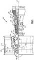
- FIG. 1schematically illustrates a gas turbine engine 20.
- the gas turbine engine 20is disclosed herein as a two-spool turbofan that generally incorporates a fan section 22, a compressor section 24, a combustor section 26 and a turbine section 28.
- Alternative enginesmight include an augmentor section (not shown) among other systems or features.
- the fan section 22drives air along a bypass flow path B in a bypass duct defined within a nacelle 15, while the compressor section 24 drives air along a core flow path C for compression and communication into the combustor section 26 then expansion through the turbine section 28.
- the exemplary engine 20generally includes a low speed spool 30 and a high speed spool 32 mounted for rotation about an engine central longitudinal axis A relative to an engine static structure 36 via several bearing systems 38. It should be understood that various bearing systems 38 at various locations may alternatively or additionally be provided, and the location of bearing systems 31 may be varied as appropriate to the application.
- the low speed spool 30generally includes an inner shaft 40 that interconnects a fan 42, a low pressure compressor 44 and a low pressure turbine 46.
- the inner shaft 40is connected to the fan 42 through a speed change mechanism, which in exemplary gas turbine engine 20 is illustrated as a geared architecture 48 to drive the fan 42 at a lower speed than the low speed spool 30.
- the high speed spool 32includes an outer shaft 50 that interconnects a high pressure compressor 52 and high pressure turbine 54.
- a combustor 56is arranged in exemplary gas turbine 20 between the high pressure compressor 52 and the high pressure turbine 54.
- a mid-turbine frame 57 of the engine static structure 36is arranged generally between the high pressure turbine 54 and the low pressure turbine 46.
- the mid-turbine frame 57further supports bearing systems 38 in the turbine section 28.
- the inner shaft 40 and the outer shaft 50are concentric and rotate via bearing systems 38 about the engine central longitudinal axis A which is collinear with their longitudinal axes.
- the core airflowis compressed by the low pressure compressor 44 then the high pressure compressor 52, mixed and burned with fuel in the combustor 56, then expanded over the high pressure turbine 54 and low pressure turbine 46.
- the mid-turbine frame 57includes airfoils 59 which are in the core airflow path C.
- the turbines 46, 54rotationally drive the respective low speed spool 30 and high speed spool 32 in response to the expansion.
- gear system 50may be located aft of combustor section 26 or even aft of turbine section 28, and fan section 22 may be positioned forward or aft of the location of gear system 48.
- the engine 20 in one exampleis a high-bypass geared aircraft engine.
- the engine 20 bypass ratiois greater than about six (6), with an example embodiment being greater than about ten (10)
- the geared architecture 48is an epicyclic gear train, such as a planetary gear system or other gear system, with a gear reduction ratio of greater than about 2.3
- the low pressure turbine 46has a pressure ratio that is greater than about five.
- the engine 20 bypass ratiois greater than about ten (10:1)
- the fan diameteris significantly larger than that of the low pressure compressor 44
- the low pressure turbine 46has a pressure ratio that is greater than about five 5:1.
- Low pressure turbine 46 pressure ratiois pressure measured prior to inlet of low pressure turbine 46 as related to the pressure at the outlet of the low pressure turbine 46 prior to an exhaust nozzle.
- the geared architecture 48may be an epicycle gear train, such as a planetary gear system or other gear system, with a gear reduction ratio of greater than about 2.3:1. It should be understood, however, that the above parameters are only exemplary of one embodiment of a geared architecture engine and that the present invention is applicable to other gas turbine engines including direct drive turbofans.
- the fan section 22 of the engine 20is designed for a particular flight condition -- typically cruise at about 0.8 Mach and about 35,000 feet (10,668 m).
- the flight condition of 0.8 Mach and 35,000 ft (10,668 m), with the engine at its best fuel consumption - also known as "bucket cruise Thrust Specific Fuel Consumption ('TSFC')" -is the industry standard parameter of lbm of fuel being burned divided by lbf of thrust the engine produces at that minimum point.
- "Low fan pressure ratio”is the pressure ratio across the fan blade alone, without a Fan Exit Guide Vane (“FEGV”) system.
- the low fan pressure ratio as disclosed herein according to one non-limiting embodimentis less than about 1.45.
- the "Low corrected fan tip speed" as disclosed herein according to one non-limiting embodimentis less than about 1150 ft / second (350.5 m/s).
- a pump system 61includes a main pump 66 and an auxiliary pump 63.
- the auxiliary pumpshown schematically in Figure 1 , is coupled to and is driven by fan shaft 65 such that the pump 63 can operate whenever the fan shaft 65, which is driven by the geared architecture 48, is rotating.
- the auxiliary pump 63supplies liquid, such as oil, to lubricate gears and bearings of the geared architecture 48 of the fan drive gear system.
- the fan drive gear systembenefits from a relatively continuous supply of lubricating liquid whenever fan shaft 65 is rotating. At least some of the liquid supplied to fan drive gear system drains to a sump 69 ( Figure 2 ) and is eventually pumped back through the pump 63.
- the pump system 61includes a bearing compartment 71 having a compartment cavity that includes the geared architecture 48 of the fan drive gear system.
- the geared architecture 48comprises star gears 48a supported on bearings 48b, a ring gear 48c, and a sun gear 48d.
- the structure and operation of this configuration of the geared architectureis known and will not be discussed in detail. Further, this is just one example of a geared architecture, and it should be understood that other configurations could also be used.
- the pump system 61also includes a gutter 73, an auxiliary reservoir 75, a first shuttle valve 60, a second shuttle valve 62, a main reservoir 64, and a scavenge pump 67 positioned outside of bearing compartment 71.
- Passages 68, 70, 72, 74, 76, 78, 80, 82, 85, 86, and -89connect the various components as illustrated and as further described, below.
- auxiliary reservoir 75is kept substantially full of liquid for later use. In one example, the auxiliary reservoir 75 holds enough liquid to provide adequate lubrication for the fan drive gear system for at least 10 seconds.
- the gutter 73does not collect all liquid leaving fan drive gear system. The remaining liquid that is not collected by gutter 73 falls to sump 69, which is an open-top reservoir at a bottom of the bearing compartment 71.
- the bearing compartment 71can be sealed to reduce liquid flow out of bearing compartment 71, except through designated passages as herein described.
- the first shuttle valve 60is fluidically connected to the auxiliary reservoir 75 via a first passage 68, to sump 69 via a second passage 70, to auxiliary pump 63 via a third passage 72, and again to sump 69 via a fourth passage 74.
- the second shuttle valve 62is fluidically connected to auxiliary pump 63 via a fifth passage 76, to main pump 66 via a sixth passage 78, to bearings 48b via a seventh passage 80, and to main reservoir 64 via eighth and ninth passages 82 and 89.
- the fifth passage 76is an auxiliary supply passage
- the sixth passage 78is a main supply passage.
- the main reservoir 64is further connected to the main pump 66 through a tenth passage -85.
- the scavenge pump 67is connected to sump 69 via an eleventh passage 86 and to the main reservoir 64 via the ninth passage 89.
- the scavenge pump 67pumps a portion of the liquid in sump 69 to the main reservoir 64 for use by the main pump 66.
- the first shuttle valve 60 and second shuttle valve 62work together as a valve system.
- This valve systemdirects lubricating liquid to bearings 48b from one of the sump 69, auxiliary reservoir 75, or main reservoir 64.
- the pump system 61selects among these potential sources of lubricating liquid based upon sensed engine operating conditions.
- the operation of the pump system 61 and the associated first 60 and second 62 shuttle valvesis described in detail in United States Patent No. 8,230, 974 , which is assigned to the assignee of the present disclosure, and which is herein incorporated by reference.
- the pump system 61also includes a main filter 81, one or more heat exchangers 82, and a self-cleaning filter 84.
- oil leaving the main pump 66goes through the main filter 81, which is located in the sixth passage 78, and then enters a set of heat exchangers (HEX) 82.
- the heat exchangers 82can include fuel/oil and air/oil configurations; however, other combinations of heat exchangers could also be used.
- the main oilis directed to the second shuttle valve 62 after exiting the heat exchangers 82. If the pressure in the main supply, i.e.
- the sixth passage 78is low, then windmill oil will be directed to the journal bearings 48b via the auxiliary, i.e. fifth passage 76. If the pressure in the main supply passage 78 is normal, then the main oil will be directed to the journal bearings 48b and windmill oil will be sent to the main reservoir via the fifth and ninth passages 76, 89 to be recycled within the oil system.
- the self-cleaning filter 84is positioned in the seventh passage 80 downstream of the second shuttle valve 62. This filter 84 removes debris from the oil prior to lubricating the bearing journals.
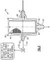
- the self-cleaning filter 84is shown in greater detail in Figure 3 .
- the self-cleaning filter 84includes a filter housing 86, defining an internal cavity, and having an inlet 88 and first 90 and second 92 outlets.
- An oil screen 94is inserted into the internal cavity and is secured to the filter housing 86 with a retainer 96.
- the retainer 96comprises a snap ring; however, other retainers could also be used.
- the oil screen 94includes a plurality of screen holes that can be set to filter the oil to a desired particle size. In one example configuration, the screen is set to filter oil to 75 microns.
- the inlet 88receives a connector 98 for connection to main line 78.
- the line 78is slightly oversized compared to prior lines to provide a slight overflow condition at the inlet 88.
- the first outlet 90receives a connector 100 for connection to the seventh passage 80 to the bearings 48b. Oil flows through the inlet 88, debris is collected on the screen 94, and the filtered oil is directed to the first outlet 90.
- the second outlet 92has a connector 102 that is connected to a twelfth passage 104 ( Figure 2 ), which returns any oil not exiting from the first outlet 90 to the bearing compartment 71.
- a restrictor 106is positioned within the twelfth passage 104 to set the amount of flow.
- the inlet flowis approximately 105 lbs/min and the outlet flow to the bearings 48b at the first outlet 90 is 100 lbs/min.
- the outlet flow to the bearings 48bis less than the inlet flow by approximately 5 lbs/min.
- This differenceis set by the restrictor 106, which then allows the remaining oil to exit the second outlet at a flow rate of 5 lbs/min.
- the excess flowwashes over the screen 94 and removes the collected debris. This oil and debris then exit the housing via the second outlet 92 and is returned to the bearing compartment.
- the housing 86is configured to be mounted externally to the engine cases such that the filter is easily accessible without having to disassemble the engine.
- the filter 84is also compact in size such that only a small amount of packaging space is required. In one example, the filter is approximately six inches by three inches. Debris collects on the screen 94 such that it is not introduced into the bearings 48b. The debris collected on the screen 94 is washed off by the oil flow and returned to the bearing compartment. Due to the self-cleaning nature of the filter, maintenance is not required; however, due to the location the screen 94 can be easily removed by releasing the snap ring and pulling the filter out with an appropriate tool.
- the subject self-cleaning filter 84protects the journal bearings 48b while sending the residual debris to a safe engine area that is less sensitive to contamination. Further, this filter 84 is located outside of the engine cases so that the filter can be easily removed and inspected; however, due to the self-cleaning feature the filter should not require periodic maintenance. Thus, the filter system will provide additional protection for the journal bearings without the need for periodic maintenance or the concern of clogging filters buried deep within the engine architecture and not easily accessed.
Landscapes
- Engineering & Computer Science (AREA)
- Mechanical Engineering (AREA)
- General Engineering & Computer Science (AREA)
- Chemical & Material Sciences (AREA)
- Combustion & Propulsion (AREA)
- Structures Of Non-Positive Displacement Pumps (AREA)
Description
- In many gas turbine engines, a low pressure spool includes a low pressure turbine that is connected to and drives a low pressure compressor, and a high pressure spool includes a high pressure turbine that is connected to and drives a high pressure compressor. In certain configurations, the low pressure spool drives a fan via a geared architecture. A lubrication system includes a main pump that is driven by the high pressure spool to pump lubricating and cooling liquid to engine components as needed.
- Some gas turbine engines include a windmill emergency oil system to protect the fan drive gear system under low or no oil conditions. For example, when the high pressure spool stops rotating or rotates at a reduced rpm (revolutions per minute), the fan drive gear system can continue rotating even though the main pump will ordinarily provide little or no liquid during this time. Such a situation can arise when the wind rotates the fan and corresponding gears and bearings while the aircraft is parked on the ground, or during an in-flight engine shutdown. The windmill emergency oil system operates to protect gears and bearings from damage during the relatively short periods of non-lubricated operation.
- Over time, these lubrication systems can become clogged with debris. In certain applications a filter has been installed to protect bearings within the fan drive system from debris. One problem with existing filters is that the filter permanently traps debris such that the debris remains in place until the fan drive gear system is overhauled. Further, in one known configuration, the filter is located within the fan drive gear system bearing journals such that the entire engine needs to be disassembled to remove and change the filter. Another problem with existing systems is that upon engine start-up and shut-down, the windmill system can send un-filtered lubrication to the journal bearings, which further clogs the filters with debris over time.
US 4,905,644 discloses a prior art pump system.EP 2 253 805 A shows a prior art pump system according to the preamble of claim 1.US 3,432,005 discloses prior art self-cleaning oil filter systems.- According to a first aspect of the present invention, there is provided a pump system as set forth in claim 1.
- In an embodiment, the self-cleaning filter comprises a filter screen positioned within a filter housing. The filter housing has a filter inlet fluidly connected to the outlet of the at least one valve. A first outlet is fluidly connected to the geared architecture. A second outlet is fluidly connected to the bearing compartment.
- In another embodiment according to any of the previous embodiments, fluid flows into the filter inlet at a first flow rate and flows out of the first outlet at a flow rate that is less than the first flow rate.
- In another embodiment according to any of the previous embodiments, fluid flows out of the second outlet at a third flow rate that is less than the second flow rate.
- In another embodiment according to any of the previous embodiments, the second flow rate is approximately 95% of the first flow rate.
- In another embodiment according to any of the previous embodiments, the filter screen is set to filter to a level comprising approximately 75 microns.
- In another embodiment according to any of the previous embodiments, the at least one valve comprises a first valve fluidly connecting the auxiliary pump to an auxiliary reservoir and a second valve fluidly connecting the main pump to the geared architecture.
- In another embodiment according to any of the previous embodiments, the second valve includes the outlet to the self-cleaning filter and includes an additional outlet fluidly connected to a main reservoir.
- In another embodiment according to any of the previous embodiments, during a first condition, fluid flows from the main reservoir, through the main pump, through the first valve inlet of the second valve, through the self-cleaning filter, and into the geared architecture. During a second condition, fluid flows from the auxiliary reservoir, through the first valve and into the auxiliary pump, through the second valve inlet to the second valve, through the self-cleaning filter, and into the geared architecture.
- In another embodiment according to any of the previous embodiments, fluid washes over the screen to remove collected debris and exits the second outlet of the self-cleaning filter to return fluid to the bearing compartment during the first and second conditions.
- In another embodiment according to any of the previous embodiments, including a main supply passage fluidly connecting the main pump to the first valve inlet of the second valve. The first condition has a normal operational pressure level in the main supply passage and the second condition has a low operational pressure level in the main supply passage.
- In another embodiment according to any of the previous embodiments, the geared architecture includes a plurality of gears supported by journal bearings. The first outlet of the filter housing is fluidly connected to lubricate the journal bearings.
- According to a further aspect of the present invention, there is provided a gas turbine engine as set forth in claim 12.
- In another embodiment according to any of the previous embodiments, fluid enters the filter housing via the filter inlet. A first portion of the fluid is filtered through the filter screen and exits the first outlet to provide filtered fluid to journal bearings of the geared architecture. A second portion of the fluid washes over the filter screen to remove collected debris and exits the second outlet of the self-cleaning filter to return the fluid and associated debris to the bearing compartment.
- According to a further aspect of the present invention, there is provided a method as set forth in claim 14.
- In another embodiment according to any of the previous embodiments, the self-cleaning filter has a housing defining an internal cavity and a filter screen positioned within the internal cavity, and includes the steps of receiving fluid at the inlet at a first flow rate, filtering a portion of the fluid through the filter screen, directing the filtered fluid to the first outlet at a second flow rate less than the first flow rate, and washing a remaining portion of the fluid over the filter screen to remove collected debris, with the remaining fluid and associated debris exiting the second outlet at a third flow rate less than the second flow rate.
- The disclosure can be further understood by reference to the following detailed description when considered in connection with the accompanying drawings wherein:
Figure 1 schematically illustrates a geared turbofan engine embodiment.Figure 2 is a schematic view of a pump system of the present invention.Figure 3 is a partial section view of a self-cleaning filter as used in the pump system ofFigure 2 .Figure 1 schematically illustrates agas turbine engine 20. Thegas turbine engine 20 is disclosed herein as a two-spool turbofan that generally incorporates afan section 22, acompressor section 24, acombustor section 26 and aturbine section 28. Alternative engines might include an augmentor section (not shown) among other systems or features. Thefan section 22 drives air along a bypass flow path B in a bypass duct defined within anacelle 15, while thecompressor section 24 drives air along a core flow path C for compression and communication into thecombustor section 26 then expansion through theturbine section 28. Although depicted as a two-spool turbofan gas turbine engine in the disclosed non-limiting embodiment, it should be understood that the concepts described herein are not limited to use with two-spool turbofans as the teachings may be applied to other types of turbine engines including three-spool architectures.- The
exemplary engine 20 generally includes alow speed spool 30 and ahigh speed spool 32 mounted for rotation about an engine central longitudinal axis A relative to an enginestatic structure 36 viaseveral bearing systems 38. It should be understood thatvarious bearing systems 38 at various locations may alternatively or additionally be provided, and the location of bearing systems 31 may be varied as appropriate to the application. - The
low speed spool 30 generally includes aninner shaft 40 that interconnects afan 42, alow pressure compressor 44 and alow pressure turbine 46. Theinner shaft 40 is connected to thefan 42 through a speed change mechanism, which in exemplarygas turbine engine 20 is illustrated as a gearedarchitecture 48 to drive thefan 42 at a lower speed than thelow speed spool 30. Thehigh speed spool 32 includes anouter shaft 50 that interconnects ahigh pressure compressor 52 andhigh pressure turbine 54. Acombustor 56 is arranged inexemplary gas turbine 20 between thehigh pressure compressor 52 and thehigh pressure turbine 54. Amid-turbine frame 57 of the enginestatic structure 36 is arranged generally between thehigh pressure turbine 54 and thelow pressure turbine 46. Themid-turbine frame 57 further supports bearingsystems 38 in theturbine section 28. Theinner shaft 40 and theouter shaft 50 are concentric and rotate viabearing systems 38 about the engine central longitudinal axis A which is collinear with their longitudinal axes. - The core airflow is compressed by the
low pressure compressor 44 then thehigh pressure compressor 52, mixed and burned with fuel in thecombustor 56, then expanded over thehigh pressure turbine 54 andlow pressure turbine 46. Themid-turbine frame 57 includesairfoils 59 which are in the core airflow path C. Theturbines low speed spool 30 andhigh speed spool 32 in response to the expansion. It will be appreciated that each of the positions of thefan section 22,compress section 24,combustor section 26,turbine section 28, and fandrive gear system 50 may be varied. For example,gear system 50 may be located aft ofcombustor section 26 or even aft ofturbine section 28, andfan section 22 may be positioned forward or aft of the location ofgear system 48. - The
engine 20 in one example is a high-bypass geared aircraft engine. In a further example, theengine 20 bypass ratio is greater than about six (6), with an example embodiment being greater than about ten (10), the gearedarchitecture 48 is an epicyclic gear train, such as a planetary gear system or other gear system, with a gear reduction ratio of greater than about 2.3 and thelow pressure turbine 46 has a pressure ratio that is greater than about five. In one disclosed embodiment, theengine 20 bypass ratio is greater than about ten (10:1), the fan diameter is significantly larger than that of thelow pressure compressor 44, and thelow pressure turbine 46 has a pressure ratio that is greater than about five 5:1.Low pressure turbine 46 pressure ratio is pressure measured prior to inlet oflow pressure turbine 46 as related to the pressure at the outlet of thelow pressure turbine 46 prior to an exhaust nozzle. The gearedarchitecture 48 may be an epicycle gear train, such as a planetary gear system or other gear system, with a gear reduction ratio of greater than about 2.3:1. It should be understood, however, that the above parameters are only exemplary of one embodiment of a geared architecture engine and that the present invention is applicable to other gas turbine engines including direct drive turbofans. - A significant amount of thrust is provided by the bypass flow B due to the high bypass ratio. The
fan section 22 of theengine 20 is designed for a particular flight condition -- typically cruise at about 0.8 Mach and about 35,000 feet (10,668 m). The flight condition of 0.8 Mach and 35,000 ft (10,668 m), with the engine at its best fuel consumption - also known as "bucket cruise Thrust Specific Fuel Consumption ('TSFC')" - is the industry standard parameter of lbm of fuel being burned divided by lbf of thrust the engine produces at that minimum point. "Low fan pressure ratio" is the pressure ratio across the fan blade alone, without a Fan Exit Guide Vane ("FEGV") system. The low fan pressure ratio as disclosed herein according to one non-limiting embodiment is less than about 1.45. "Low corrected fan tip speed" is the actual fan tip speed in ft/sec divided by an industry standard temperature correction of [(Tram °R) / (518.7 °R)]0.5 (where °R = K x 9/5). The "Low corrected fan tip speed" as disclosed herein according to one non-limiting embodiment is less than about 1150 ft / second (350.5 m/s). - As shown in
Figure 2 , apump system 61 includes amain pump 66 and anauxiliary pump 63. The auxiliary pump, shown schematically inFigure 1 , is coupled to and is driven byfan shaft 65 such that thepump 63 can operate whenever thefan shaft 65, which is driven by the gearedarchitecture 48, is rotating. Theauxiliary pump 63 supplies liquid, such as oil, to lubricate gears and bearings of the gearedarchitecture 48 of the fan drive gear system. The fan drive gear system benefits from a relatively continuous supply of lubricating liquid wheneverfan shaft 65 is rotating. At least some of the liquid supplied to fan drive gear system drains to a sump 69 (Figure 2 ) and is eventually pumped back through thepump 63. - As shown in
Figure 2 , thepump system 61 includes abearing compartment 71 having a compartment cavity that includes the gearedarchitecture 48 of the fan drive gear system. In one example, the gearedarchitecture 48 comprisesstar gears 48a supported onbearings 48b, aring gear 48c, and asun gear 48d. The structure and operation of this configuration of the geared architecture is known and will not be discussed in detail. Further, this is just one example of a geared architecture, and it should be understood that other configurations could also be used. - In addition to the
auxiliary pump 63 andmain pump 66, thepump system 61 also includes agutter 73, anauxiliary reservoir 75, afirst shuttle valve 60, asecond shuttle valve 62, amain reservoir 64, and ascavenge pump 67 positioned outside of bearingcompartment 71.Passages - As the fan drive gear system rotates, lubricating liquid drips or flies off the geared
architecture 48 intobearing compartment 71 in different directions. A portion of that liquid is caught and collected by thegutter 73 and is funneled to theauxiliary reservoir 75. During normal operating conditions, theauxiliary reservoir 75 is kept substantially full of liquid for later use. In one example, theauxiliary reservoir 75 holds enough liquid to provide adequate lubrication for the fan drive gear system for at least 10 seconds. Thegutter 73 does not collect all liquid leaving fan drive gear system. The remaining liquid that is not collected bygutter 73 falls tosump 69, which is an open-top reservoir at a bottom of thebearing compartment 71. Thebearing compartment 71 can be sealed to reduce liquid flow out of bearingcompartment 71, except through designated passages as herein described. - The
first shuttle valve 60 is fluidically connected to theauxiliary reservoir 75 via afirst passage 68, tosump 69 via asecond passage 70, toauxiliary pump 63 via athird passage 72, and again tosump 69 via afourth passage 74. Thesecond shuttle valve 62 is fluidically connected toauxiliary pump 63 via afifth passage 76, tomain pump 66 via asixth passage 78, tobearings 48b via aseventh passage 80, and tomain reservoir 64 via eighth andninth passages fifth passage 76 is an auxiliary supply passage and thesixth passage 78 is a main supply passage. Themain reservoir 64 is further connected to themain pump 66 through a tenth passage -85. Thescavenge pump 67 is connected tosump 69 via aneleventh passage 86 and to themain reservoir 64 via theninth passage 89. Thescavenge pump 67 pumps a portion of the liquid insump 69 to themain reservoir 64 for use by themain pump 66. - As part of
pump system 61, thefirst shuttle valve 60 andsecond shuttle valve 62 work together as a valve system. This valve system directs lubricating liquid tobearings 48b from one of thesump 69,auxiliary reservoir 75, ormain reservoir 64. Thepump system 61 selects among these potential sources of lubricating liquid based upon sensed engine operating conditions. The operation of thepump system 61 and the associated first 60 and second 62 shuttle valves is described in detail in United States Patent No.8,230, 974 , which is assigned to the assignee of the present disclosure, and which is herein incorporated by reference. - The
pump system 61 also includes amain filter 81, one ormore heat exchangers 82, and a self-cleaningfilter 84. As shown inFigure 2 , oil leaving themain pump 66 goes through themain filter 81, which is located in thesixth passage 78, and then enters a set of heat exchangers (HEX) 82. In one example, theheat exchangers 82 can include fuel/oil and air/oil configurations; however, other combinations of heat exchangers could also be used. The main oil is directed to thesecond shuttle valve 62 after exiting theheat exchangers 82. If the pressure in the main supply, i.e. thesixth passage 78, is low, then windmill oil will be directed to thejournal bearings 48b via the auxiliary, i.e.fifth passage 76. If the pressure in themain supply passage 78 is normal, then the main oil will be directed to thejournal bearings 48b and windmill oil will be sent to the main reservoir via the fifth andninth passages - The self-cleaning
filter 84 is positioned in theseventh passage 80 downstream of thesecond shuttle valve 62. Thisfilter 84 removes debris from the oil prior to lubricating the bearing journals. The self-cleaningfilter 84 is shown in greater detail inFigure 3 . - The self-cleaning
filter 84 includes afilter housing 86, defining an internal cavity, and having aninlet 88 and first 90 and second 92 outlets. Anoil screen 94 is inserted into the internal cavity and is secured to thefilter housing 86 with aretainer 96. In one example, theretainer 96 comprises a snap ring; however, other retainers could also be used. Theoil screen 94 includes a plurality of screen holes that can be set to filter the oil to a desired particle size. In one example configuration, the screen is set to filter oil to 75 microns. - The
inlet 88 receives aconnector 98 for connection tomain line 78. Theline 78 is slightly oversized compared to prior lines to provide a slight overflow condition at theinlet 88. Thefirst outlet 90 receives aconnector 100 for connection to theseventh passage 80 to thebearings 48b. Oil flows through theinlet 88, debris is collected on thescreen 94, and the filtered oil is directed to thefirst outlet 90. - The
second outlet 92 has aconnector 102 that is connected to a twelfth passage 104 (Figure 2 ), which returns any oil not exiting from thefirst outlet 90 to thebearing compartment 71. Arestrictor 106 is positioned within thetwelfth passage 104 to set the amount of flow. In one example, the inlet flow is approximately 105 lbs/min and the outlet flow to thebearings 48b at thefirst outlet 90 is 100 lbs/min. As such, the outlet flow to thebearings 48b is less than the inlet flow by approximately 5 lbs/min. This difference is set by therestrictor 106, which then allows the remaining oil to exit the second outlet at a flow rate of 5 lbs/min. The excess flow washes over thescreen 94 and removes the collected debris. This oil and debris then exit the housing via thesecond outlet 92 and is returned to the bearing compartment. - The
housing 86 is configured to be mounted externally to the engine cases such that the filter is easily accessible without having to disassemble the engine. Thefilter 84 is also compact in size such that only a small amount of packaging space is required. In one example, the filter is approximately six inches by three inches. Debris collects on thescreen 94 such that it is not introduced into thebearings 48b. The debris collected on thescreen 94 is washed off by the oil flow and returned to the bearing compartment. Due to the self-cleaning nature of the filter, maintenance is not required; however, due to the location thescreen 94 can be easily removed by releasing the snap ring and pulling the filter out with an appropriate tool. - The subject self-cleaning
filter 84 protects thejournal bearings 48b while sending the residual debris to a safe engine area that is less sensitive to contamination. Further, thisfilter 84 is located outside of the engine cases so that the filter can be easily removed and inspected; however, due to the self-cleaning feature the filter should not require periodic maintenance. Thus, the filter system will provide additional protection for the journal bearings without the need for periodic maintenance or the concern of clogging filters buried deep within the engine architecture and not easily accessed. - Although an example embodiment has been disclosed, a worker of ordinary skill in this art would recognize that certain modifications would come within the scope of the claims. For that reason, the following claims should be studied to determine their true scope and content.
Claims (15)
- A pump system (61) for a gas turbine engine comprising:at least one pump (63,66);at least one valve (60,62) having an outlet and at least one inlet fluidly connected to the at least one pump (63,66);a geared architecture (48) positioned within a bearing compartment (71), wherein the geared architecture (48) is configured to receive lubricating fluid from the outlet of the at least one valve (60,62); andthe at least one inlet of the at least one valve (60,62) comprises a first valve inlet fluidly connected to a main pump (66) and a second valve inlet fluidly connected to an auxiliary pump (63),characterised in that it further comprises:
a self-cleaning filter (84) positioned downstream of the at least one valve (60,62) and upstream of the geared architecture (48). - The pump system (61) according to claim 1, wherein the self-cleaning filter (84) comprises a filter screen (94) positioned within a filter housing (86), and the filter housing (86) has a filter inlet (88) fluidly connected to the outlet of the at least one valve (60,62), a first outlet (90) fluidly connected to the geared architecture (48), and a second outlet (92) fluidly connected to the bearing compartment (71).
- The pump system (61) according to claim 2, wherein fluid flows into the filter inlet (88) at a first flow rate and flows out of the first outlet (90) at a flow rate that is less than the first flow rate.
- The pump system (61) according to claim 3, wherein fluid flows out of the second outlet (92) at a third flow rate that is less than the second flow rate.
- The pump system (61) according to claim 4, wherein the second flow rate is approximately 95% of the first flow rate.
- The pump system (61) according to any of claims 2 to 5, wherein the filter screen (94) is set to filter to a level comprising approximately 75 microns.
- The pump system (61) according to any of claims 2 to 6, wherein the at least one valve (60,62) comprises a first valve (60) fluidly connecting the auxiliary pump (63) to an auxiliary reservoir (75) and a second valve (62) fluidly connecting the main pump (66) to the geared architecture (48).
- The pump system (61) according to claim 7, wherein the second valve (62) includes the outlet to the self-cleaning filter (84) and includes an additional outlet fluidly connected to a main reservoir (64).
- The pump system (61) according to claim 8, wherein during a first condition fluid flows from the main reservoir (64), through the main pump (66), through the first valve inlet of the second valve (62), through the self-cleaning filter (84), and into the geared architecture (48), and during a second condition fluid flows from the auxiliary reservoir (75), through the first valve (60) and into the auxiliary pump (63), through the second valve inlet to the second valve (62), through the self-cleaning filter (84), and into the geared architecture (48).
- The pump system (61) according to claim 9, wherein fluid washes over the screen (94) to remove collected debris and exits the second outlet of the self-cleaning filter (84) to return fluid to the bearing compartment (71) during the first and second conditions.
- The pump system (61) according to claim 9 or 10, including a main supply passage (78) fluidly connecting the main pump (66) to the first valve inlet of the second valve (62), and wherein the first condition comprises a normal operational pressure level in the main supply passage (78) and the second condition comprises a low operational pressure level in the main supply passage (78), optionally wherein the geared architecture (48) includes a plurality of gears (48a,48c,48d) supported by journal bearings (48b), and wherein the first outlet of the filter housing (86) is fluidly connected to lubricate the journal bearings (48b).
- A gas turbine engine (20) comprising:a fan section (22) including a fan shaft (65);a first spool (30) including a first shaft (40) that connects the fan section (22) and a first compressor section (44) to a first turbine section (46);a second spool (32) including a second shaft (50) that connects a second compressor section (52) to a second turbine section (54), the first and second shafts (40,50) rotating a different speeds; anda lubrication system including the pump system (61) of any preceding claim, wherein the geared architecture (48) couples the first shaft (40) to the fan shaft (65), optionally wherein the geared architecture (48) includes a plurality of gears (48a,48c,48d) supported by journal bearings (48b), and wherein the filter (84) includes an outlet (90,92) that is fluidly connected to lubricate the journal bearings (48b).
- The gas turbine engine (20) according to claim 12, wherein fluid enters the filter housing (86) via the filter inlet (88), a first portion of the fluid is filtered through the filter screen (94) and exits the first outlet (90) to provide filtered fluid to journal bearings (48b) of the geared architecture (48), and a second portion of the fluid washes over the filter screen (94) to remove collected debris and exits the second outlet (92) of the self-cleaning filter to return the fluid and associated debris to the bearing compartment (71), optionally wherein the first portion of fluid is significantly greater than the second portion of fluid.
- A method of cleaning a filter in a pump system (61) for a gas turbine engine (20) comprising the steps of:providing a self-cleaning filter (84) having an inlet (88), a first outlet (90), and a second outlet (92);fluidly connecting the inlet (88) to a fluid supply associated with a main reservoir (64); andfluidly connecting the second outlet (92) to return collected debris to a bearing compartment (71) that receives a geared architecture (48),the method further comprises:fluidly connecting the inlet (88) with an auxiliary reservoir (75); andfluidly connecting the first outlet (90) to lubricate bearings (48b) of the geared architecture (48) that couples an engine shaft (40) to a fan shaft (65).
- The method according to claim 14, wherein the self-cleaning filter (84) comprises a housing (86) defining an internal cavity and a filter screen (94) positioned within the internal cavity, and including the steps of
receiving fluid at the inlet (88) at a first flow rate,
filtering a portion of the fluid through the filter screen (94),
directing the filtered fluid to the first outlet (90) at a second flow rate less than the first flow rate, and
washing a remaining portion of the fluid over the filter screen (94) to remove collected debris, with the remaining fluid and associated debris exiting the second outlet (92) at a third flow rate less than the second flow rate.
Applications Claiming Priority (2)
| Application Number | Priority Date | Filing Date | Title |
|---|---|---|---|
| US201361770369P | 2013-02-28 | 2013-02-28 | |
| PCT/US2014/017025WO2014133836A1 (en) | 2013-02-28 | 2014-02-19 | Self cleaning debris filter for fan drive gear system |
Publications (3)
| Publication Number | Publication Date |
|---|---|
| EP2961969A1 EP2961969A1 (en) | 2016-01-06 |
| EP2961969A4 EP2961969A4 (en) | 2016-10-19 |
| EP2961969B1true EP2961969B1 (en) | 2019-06-05 |
Family
ID=51428702
Family Applications (1)
| Application Number | Title | Priority Date | Filing Date |
|---|---|---|---|
| EP14756659.0AActiveEP2961969B1 (en) | 2013-02-28 | 2014-02-19 | Self cleaning debris filter for fan drive gear system |
Country Status (3)
| Country | Link |
|---|---|
| US (1) | US9995177B2 (en) |
| EP (1) | EP2961969B1 (en) |
| WO (1) | WO2014133836A1 (en) |
Families Citing this family (17)
| Publication number | Priority date | Publication date | Assignee | Title |
|---|---|---|---|---|
| US9840966B2 (en)* | 2014-01-03 | 2017-12-12 | United Technologies Corporation | Auxiliaryy fluid flow system debris filter |
| EP3102807B1 (en)* | 2014-01-20 | 2022-04-20 | Raytheon Technologies Corporation | Auxiliary oil system for geared gas turbine engine |
| US10208625B2 (en)* | 2014-12-16 | 2019-02-19 | United Technologies Corporation | Temporary post maintenance oil filter for gas-turbine engine |
| US10513949B2 (en) | 2016-09-09 | 2019-12-24 | United Technologies Corporation | Auxiliary journal oil supply system |
| US10450894B2 (en) | 2016-11-28 | 2019-10-22 | United Technologies Corporation | Bearing compartment scavenge control |
| US10711642B2 (en)* | 2017-03-31 | 2020-07-14 | Raytheon Technologies Corporation | Gas turbine engine lubrication system and apparatus with boost pump system |
| US10724445B2 (en) | 2018-01-03 | 2020-07-28 | Raytheon Technologies Corporation | Method of assembly for fan drive gear system with rotating carrier |
| EP3557010B1 (en) | 2018-04-17 | 2021-02-24 | Rolls-Royce Deutschland Ltd & Co KG | Gas turbine engine |
| EP3557028B1 (en) | 2018-04-17 | 2022-06-01 | Rolls-Royce Deutschland Ltd & Co KG | Gas turbine engine |
| US12259036B2 (en)* | 2018-04-20 | 2025-03-25 | Rtx Corporation | Electric motor driven auxiliary oil system for geared gas turbine engine |
| DE102018120511A1 (en)* | 2018-08-22 | 2020-02-27 | Rolls-Royce Deutschland Ltd & Co Kg | Gas turbine engine |
| US11555418B2 (en)* | 2019-06-12 | 2023-01-17 | General Electric Company | Oil supply system for a gas turbine engine |
| US11542844B2 (en)* | 2019-09-20 | 2023-01-03 | Raytheon Technologies Corporation | Integrated lubricating fluid filtering and metering device |
| GB202005916D0 (en)* | 2020-04-23 | 2020-06-10 | Rolls Royce Plc | Gas turbine engine lubrication system |
| CN111963494B (en)* | 2020-08-31 | 2022-03-18 | 江华六月香果业股份有限公司 | Anti-blocking water pump provided with filtering device and used for agricultural irrigation |
| FR3133889B1 (en)* | 2022-03-23 | 2024-04-19 | Safran Aircraft Engines | Oil supply assembly for a turbomachine accessory box |
| DE102022119807A1 (en)* | 2022-08-05 | 2024-02-08 | Rolls-Royce Deutschland Ltd & Co Kg | Gearbox, gas turbine engine with a gearbox and method for determining a filter fineness of a filter device of a gearbox |
Family Cites Families (21)
| Publication number | Priority date | Publication date | Assignee | Title |
|---|---|---|---|---|
| US3432005A (en)* | 1966-08-31 | 1969-03-11 | Ford Motor Co | Self-cleaning oil filter systems |
| GB1110249A (en) | 1967-01-27 | 1968-04-18 | Rolls Royce | Filter device |
| GB1112783A (en) | 1967-03-01 | 1968-05-08 | Rolls Royce | Improvements in or relating to apparatus for filtering liquids |
| US4456425A (en) | 1980-11-20 | 1984-06-26 | General Electric Company | Modular inlet gearbox for a gas turbine engine |
| US4525995A (en) | 1983-04-04 | 1985-07-02 | Williams International Corporation | Oil scavening system for gas turbine engine |
| FR2630160B1 (en) | 1988-04-13 | 1990-07-20 | Snecma | FILTRATION DEVICE, PARTICULARLY FOR A LUBRICATION CIRCUIT OF A TURBOMACHINE |
| IT8846845A0 (en)* | 1988-05-10 | 1988-05-10 | Universal Filter Spa | DISPOSABLE FILTERING UNIT FOR TRIPLE FILTRATION OIL |
| EP0835158B1 (en)* | 1995-06-17 | 1999-03-03 | Knecht Filterwerke Gmbh | Lubricant oil filter intended for use in particular in internal combustion engines |
| US5610341A (en) | 1996-04-08 | 1997-03-11 | General Electric Company | Modular oil monitor |
| GB9904221D0 (en) | 1999-02-25 | 1999-04-21 | Rolls Royce Plc | Gas turbine engine bearing arrangement |
| US7426834B2 (en)* | 2004-02-03 | 2008-09-23 | General Electric Company | “Get home” oil supply and scavenge system |
| US7640723B2 (en) | 2005-12-16 | 2010-01-05 | Hamilton Sundstrand Corporation | Engine with fuel/lubricant supply system for bearing lubrication |
| US7937946B1 (en) | 2005-12-21 | 2011-05-10 | Florida Turbine Technologies, Inc. | Small gas turbine engine with lubricated bearings |
| US8939864B2 (en) | 2006-08-15 | 2015-01-27 | United Technologies Corporation | Gas turbine engine lubrication |
| US7841478B2 (en)* | 2007-10-26 | 2010-11-30 | Remy Mangano | Self-cleaning filter and filtration system for lubricants |
| KR100998875B1 (en) | 2008-10-29 | 2010-12-08 | 제일모직주식회사 | Weather resistant thermoplastic resin with excellent low light properties and its manufacturing method |
| US8307626B2 (en)* | 2009-02-26 | 2012-11-13 | United Technologies Corporation | Auxiliary pump system for fan drive gear system |
| US8230974B2 (en)* | 2009-05-22 | 2012-07-31 | United Technologies Corporation | Windmill and zero gravity lubrication system for a gas turbine engine |
| US8398517B2 (en) | 2009-06-10 | 2013-03-19 | United Technologies Corporation | Journal bearing with single unit jumper tube and filter |
| US8246503B2 (en) | 2009-06-10 | 2012-08-21 | United Technologies Corporation | Epicyclic gear system with improved lubrication system |
| US8261527B1 (en) | 2012-01-31 | 2012-09-11 | United Technologies Corporation | Gas turbine engine with geared turbofan and oil thermal management system with unique heat exchanger structure |
- 2014
- 2014-02-19EPEP14756659.0Apatent/EP2961969B1/enactiveActive
- 2014-02-19USUS14/761,428patent/US9995177B2/enactiveActive
- 2014-02-19WOPCT/US2014/017025patent/WO2014133836A1/enactiveApplication Filing
Non-Patent Citations (1)
| Title |
|---|
| None* |
Also Published As
| Publication number | Publication date |
|---|---|
| EP2961969A4 (en) | 2016-10-19 |
| US9995177B2 (en) | 2018-06-12 |
| WO2014133836A1 (en) | 2014-09-04 |
| US20160032772A1 (en) | 2016-02-04 |
| EP2961969A1 (en) | 2016-01-06 |
Similar Documents
| Publication | Publication Date | Title |
|---|---|---|
| EP2961969B1 (en) | Self cleaning debris filter for fan drive gear system | |
| US11203974B2 (en) | Auxiliary oil system for geared gas turbine engine | |
| EP3293363B1 (en) | Auxiliary journal oil supply system | |
| EP2949884B1 (en) | Scavenge filter system for a gas turbine engine | |
| EP2855859B1 (en) | Direct feed auxiliary oil system for geared turbofan engine | |
| EP3557000B1 (en) | Auxiliary oil system for geared gas turbine engine | |
| EP2898202B1 (en) | Lubrication system having porous feature | |
| EP2893244B1 (en) | Lubrication system having segmented anti-backflow feature | |
| EP3699413B1 (en) | Fan drive gear system manifold radial tube filters | |
| US20140140824A1 (en) | Oil system bearing compartment architecture for gas turbine engine | |
| WO2015147949A2 (en) | Auxiliary oil system for geared gas turbine engine | |
| EP2964929B1 (en) | Oil system debris monitor system for a gas turbine engine |
Legal Events
| Date | Code | Title | Description |
|---|---|---|---|
| PUAI | Public reference made under article 153(3) epc to a published international application that has entered the european phase | Free format text:ORIGINAL CODE: 0009012 | |
| 17P | Request for examination filed | Effective date:20150917 | |
| AK | Designated contracting states | Kind code of ref document:A1 Designated state(s):AL AT BE BG CH CY CZ DE DK EE ES FI FR GB GR HR HU IE IS IT LI LT LU LV MC MK MT NL NO PL PT RO RS SE SI SK SM TR | |
| AX | Request for extension of the european patent | Extension state:BA ME | |
| DAX | Request for extension of the european patent (deleted) | ||
| A4 | Supplementary search report drawn up and despatched | Effective date:20160921 | |
| RIC1 | Information provided on ipc code assigned before grant | Ipc:F02C 7/36 20060101AFI20160915BHEP Ipc:F01D 15/12 20060101ALI20160915BHEP | |
| RAP1 | Party data changed (applicant data changed or rights of an application transferred) | Owner name:UNITED TECHNOLOGIES CORPORATION | |
| STAA | Information on the status of an ep patent application or granted ep patent | Free format text:STATUS: REQUEST FOR EXAMINATION WAS MADE | |
| GRAP | Despatch of communication of intention to grant a patent | Free format text:ORIGINAL CODE: EPIDOSNIGR1 | |
| STAA | Information on the status of an ep patent application or granted ep patent | Free format text:STATUS: GRANT OF PATENT IS INTENDED | |
| RIC1 | Information provided on ipc code assigned before grant | Ipc:F01D 25/16 20060101ALI20181120BHEP Ipc:F02C 7/06 20060101ALI20181120BHEP Ipc:F01M 1/10 20060101ALI20181120BHEP Ipc:F01D 5/02 20060101ALI20181120BHEP Ipc:F02C 7/36 20060101AFI20181120BHEP Ipc:F01D 15/12 20060101ALI20181120BHEP Ipc:F01D 25/20 20060101ALI20181120BHEP | |
| INTG | Intention to grant announced | Effective date:20181214 | |
| GRAS | Grant fee paid | Free format text:ORIGINAL CODE: EPIDOSNIGR3 | |
| GRAA | (expected) grant | Free format text:ORIGINAL CODE: 0009210 | |
| STAA | Information on the status of an ep patent application or granted ep patent | Free format text:STATUS: THE PATENT HAS BEEN GRANTED | |
| AK | Designated contracting states | Kind code of ref document:B1 Designated state(s):AL AT BE BG CH CY CZ DE DK EE ES FI FR GB GR HR HU IE IS IT LI LT LU LV MC MK MT NL NO PL PT RO RS SE SI SK SM TR | |
| REG | Reference to a national code | Ref country code:GB Ref legal event code:FG4D | |
| REG | Reference to a national code | Ref country code:CH Ref legal event code:EP | |
| REG | Reference to a national code | Ref country code:AT Ref legal event code:REF Ref document number:1140211 Country of ref document:AT Kind code of ref document:T Effective date:20190615 | |
| REG | Reference to a national code | Ref country code:DE Ref legal event code:R096 Ref document number:602014047856 Country of ref document:DE | |
| REG | Reference to a national code | Ref country code:IE Ref legal event code:FG4D | |
| REG | Reference to a national code | Ref country code:NL Ref legal event code:MP Effective date:20190605 | |
| REG | Reference to a national code | Ref country code:LT Ref legal event code:MG4D | |
| PG25 | Lapsed in a contracting state [announced via postgrant information from national office to epo] | Ref country code:NO Free format text:LAPSE BECAUSE OF FAILURE TO SUBMIT A TRANSLATION OF THE DESCRIPTION OR TO PAY THE FEE WITHIN THE PRESCRIBED TIME-LIMIT Effective date:20190905 Ref country code:FI Free format text:LAPSE BECAUSE OF FAILURE TO SUBMIT A TRANSLATION OF THE DESCRIPTION OR TO PAY THE FEE WITHIN THE PRESCRIBED TIME-LIMIT Effective date:20190605 Ref country code:SE Free format text:LAPSE BECAUSE OF FAILURE TO SUBMIT A TRANSLATION OF THE DESCRIPTION OR TO PAY THE FEE WITHIN THE PRESCRIBED TIME-LIMIT Effective date:20190605 Ref country code:AL Free format text:LAPSE BECAUSE OF FAILURE TO SUBMIT A TRANSLATION OF THE DESCRIPTION OR TO PAY THE FEE WITHIN THE PRESCRIBED TIME-LIMIT Effective date:20190605 Ref country code:HR Free format text:LAPSE BECAUSE OF FAILURE TO SUBMIT A TRANSLATION OF THE DESCRIPTION OR TO PAY THE FEE WITHIN THE PRESCRIBED TIME-LIMIT Effective date:20190605 Ref country code:ES Free format text:LAPSE BECAUSE OF FAILURE TO SUBMIT A TRANSLATION OF THE DESCRIPTION OR TO PAY THE FEE WITHIN THE PRESCRIBED TIME-LIMIT Effective date:20190605 Ref country code:LT Free format text:LAPSE BECAUSE OF FAILURE TO SUBMIT A TRANSLATION OF THE DESCRIPTION OR TO PAY THE FEE WITHIN THE PRESCRIBED TIME-LIMIT Effective date:20190605 | |
| PG25 | Lapsed in a contracting state [announced via postgrant information from national office to epo] | Ref country code:LV Free format text:LAPSE BECAUSE OF FAILURE TO SUBMIT A TRANSLATION OF THE DESCRIPTION OR TO PAY THE FEE WITHIN THE PRESCRIBED TIME-LIMIT Effective date:20190605 Ref country code:RS Free format text:LAPSE BECAUSE OF FAILURE TO SUBMIT A TRANSLATION OF THE DESCRIPTION OR TO PAY THE FEE WITHIN THE PRESCRIBED TIME-LIMIT Effective date:20190605 Ref country code:BG Free format text:LAPSE BECAUSE OF FAILURE TO SUBMIT A TRANSLATION OF THE DESCRIPTION OR TO PAY THE FEE WITHIN THE PRESCRIBED TIME-LIMIT Effective date:20190905 Ref country code:GR Free format text:LAPSE BECAUSE OF FAILURE TO SUBMIT A TRANSLATION OF THE DESCRIPTION OR TO PAY THE FEE WITHIN THE PRESCRIBED TIME-LIMIT Effective date:20190906 | |
| REG | Reference to a national code | Ref country code:AT Ref legal event code:MK05 Ref document number:1140211 Country of ref document:AT Kind code of ref document:T Effective date:20190605 | |
| PG25 | Lapsed in a contracting state [announced via postgrant information from national office to epo] | Ref country code:CZ Free format text:LAPSE BECAUSE OF FAILURE TO SUBMIT A TRANSLATION OF THE DESCRIPTION OR TO PAY THE FEE WITHIN THE PRESCRIBED TIME-LIMIT Effective date:20190605 Ref country code:RO Free format text:LAPSE BECAUSE OF FAILURE TO SUBMIT A TRANSLATION OF THE DESCRIPTION OR TO PAY THE FEE WITHIN THE PRESCRIBED TIME-LIMIT Effective date:20190605 Ref country code:SK Free format text:LAPSE BECAUSE OF FAILURE TO SUBMIT A TRANSLATION OF THE DESCRIPTION OR TO PAY THE FEE WITHIN THE PRESCRIBED TIME-LIMIT Effective date:20190605 Ref country code:AT Free format text:LAPSE BECAUSE OF FAILURE TO SUBMIT A TRANSLATION OF THE DESCRIPTION OR TO PAY THE FEE WITHIN THE PRESCRIBED TIME-LIMIT Effective date:20190605 Ref country code:EE Free format text:LAPSE BECAUSE OF FAILURE TO SUBMIT A TRANSLATION OF THE DESCRIPTION OR TO PAY THE FEE WITHIN THE PRESCRIBED TIME-LIMIT Effective date:20190605 Ref country code:NL Free format text:LAPSE BECAUSE OF FAILURE TO SUBMIT A TRANSLATION OF THE DESCRIPTION OR TO PAY THE FEE WITHIN THE PRESCRIBED TIME-LIMIT Effective date:20190605 Ref country code:PT Free format text:LAPSE BECAUSE OF FAILURE TO SUBMIT A TRANSLATION OF THE DESCRIPTION OR TO PAY THE FEE WITHIN THE PRESCRIBED TIME-LIMIT Effective date:20191007 | |
| PG25 | Lapsed in a contracting state [announced via postgrant information from national office to epo] | Ref country code:IT Free format text:LAPSE BECAUSE OF FAILURE TO SUBMIT A TRANSLATION OF THE DESCRIPTION OR TO PAY THE FEE WITHIN THE PRESCRIBED TIME-LIMIT Effective date:20190605 Ref country code:IS Free format text:LAPSE BECAUSE OF FAILURE TO SUBMIT A TRANSLATION OF THE DESCRIPTION OR TO PAY THE FEE WITHIN THE PRESCRIBED TIME-LIMIT Effective date:20191005 Ref country code:SM Free format text:LAPSE BECAUSE OF FAILURE TO SUBMIT A TRANSLATION OF THE DESCRIPTION OR TO PAY THE FEE WITHIN THE PRESCRIBED TIME-LIMIT Effective date:20190605 | |
| REG | Reference to a national code | Ref country code:DE Ref legal event code:R097 Ref document number:602014047856 Country of ref document:DE | |
| PG25 | Lapsed in a contracting state [announced via postgrant information from national office to epo] | Ref country code:TR Free format text:LAPSE BECAUSE OF FAILURE TO SUBMIT A TRANSLATION OF THE DESCRIPTION OR TO PAY THE FEE WITHIN THE PRESCRIBED TIME-LIMIT Effective date:20190605 | |
| PLBE | No opposition filed within time limit | Free format text:ORIGINAL CODE: 0009261 | |
| STAA | Information on the status of an ep patent application or granted ep patent | Free format text:STATUS: NO OPPOSITION FILED WITHIN TIME LIMIT | |
| PG25 | Lapsed in a contracting state [announced via postgrant information from national office to epo] | Ref country code:PL Free format text:LAPSE BECAUSE OF FAILURE TO SUBMIT A TRANSLATION OF THE DESCRIPTION OR TO PAY THE FEE WITHIN THE PRESCRIBED TIME-LIMIT Effective date:20190605 Ref country code:DK Free format text:LAPSE BECAUSE OF FAILURE TO SUBMIT A TRANSLATION OF THE DESCRIPTION OR TO PAY THE FEE WITHIN THE PRESCRIBED TIME-LIMIT Effective date:20190605 | |
| 26N | No opposition filed | Effective date:20200306 | |
| PG25 | Lapsed in a contracting state [announced via postgrant information from national office to epo] | Ref country code:SI Free format text:LAPSE BECAUSE OF FAILURE TO SUBMIT A TRANSLATION OF THE DESCRIPTION OR TO PAY THE FEE WITHIN THE PRESCRIBED TIME-LIMIT Effective date:20190605 | |
| REG | Reference to a national code | Ref country code:CH Ref legal event code:PL | |
| REG | Reference to a national code | Ref country code:BE Ref legal event code:MM Effective date:20200229 | |
| PG25 | Lapsed in a contracting state [announced via postgrant information from national office to epo] | Ref country code:MC Free format text:LAPSE BECAUSE OF FAILURE TO SUBMIT A TRANSLATION OF THE DESCRIPTION OR TO PAY THE FEE WITHIN THE PRESCRIBED TIME-LIMIT Effective date:20190605 Ref country code:LU Free format text:LAPSE BECAUSE OF NON-PAYMENT OF DUE FEES Effective date:20200219 | |
| PG25 | Lapsed in a contracting state [announced via postgrant information from national office to epo] | Ref country code:LI Free format text:LAPSE BECAUSE OF NON-PAYMENT OF DUE FEES Effective date:20200229 Ref country code:CH Free format text:LAPSE BECAUSE OF NON-PAYMENT OF DUE FEES Effective date:20200229 | |
| PG25 | Lapsed in a contracting state [announced via postgrant information from national office to epo] | Ref country code:IE Free format text:LAPSE BECAUSE OF NON-PAYMENT OF DUE FEES Effective date:20200219 | |
| PG25 | Lapsed in a contracting state [announced via postgrant information from national office to epo] | Ref country code:BE Free format text:LAPSE BECAUSE OF NON-PAYMENT OF DUE FEES Effective date:20200229 | |
| PG25 | Lapsed in a contracting state [announced via postgrant information from national office to epo] | Ref country code:MT Free format text:LAPSE BECAUSE OF FAILURE TO SUBMIT A TRANSLATION OF THE DESCRIPTION OR TO PAY THE FEE WITHIN THE PRESCRIBED TIME-LIMIT Effective date:20190605 Ref country code:CY Free format text:LAPSE BECAUSE OF FAILURE TO SUBMIT A TRANSLATION OF THE DESCRIPTION OR TO PAY THE FEE WITHIN THE PRESCRIBED TIME-LIMIT Effective date:20190605 | |
| PG25 | Lapsed in a contracting state [announced via postgrant information from national office to epo] | Ref country code:MK Free format text:LAPSE BECAUSE OF FAILURE TO SUBMIT A TRANSLATION OF THE DESCRIPTION OR TO PAY THE FEE WITHIN THE PRESCRIBED TIME-LIMIT Effective date:20190605 | |
| REG | Reference to a national code | Ref country code:DE Ref legal event code:R081 Ref document number:602014047856 Country of ref document:DE Owner name:RAYTHEON TECHNOLOGIES CORPORATION (N.D.GES.D.S, US Free format text:FORMER OWNER: UNITED TECHNOLOGIES CORP., FARMINGTON, CONN., US | |
| P01 | Opt-out of the competence of the unified patent court (upc) registered | Effective date:20230520 | |
| PGFP | Annual fee paid to national office [announced via postgrant information from national office to epo] | Ref country code:DE Payment date:20250122 Year of fee payment:12 | |
| PGFP | Annual fee paid to national office [announced via postgrant information from national office to epo] | Ref country code:FR Payment date:20250121 Year of fee payment:12 | |
| PGFP | Annual fee paid to national office [announced via postgrant information from national office to epo] | Ref country code:GB Payment date:20250123 Year of fee payment:12 |