EP2961351B1 - Devices for percutaneous tricuspid valve repair - Google Patents
Devices for percutaneous tricuspid valve repairDownload PDFInfo
- Publication number
- EP2961351B1 EP2961351B1EP14757226.7AEP14757226AEP2961351B1EP 2961351 B1EP2961351 B1EP 2961351B1EP 14757226 AEP14757226 AEP 14757226AEP 2961351 B1EP2961351 B1EP 2961351B1
- Authority
- EP
- European Patent Office
- Prior art keywords
- wire
- delivery catheter
- distal end
- catheter
- tissue anchor
- Prior art date
- Legal status (The legal status is an assumption and is not a legal conclusion. Google has not performed a legal analysis and makes no representation as to the accuracy of the status listed.)
- Active
Links
- WIWNLZXPZVXVGF-UHFFFAOYSA-NC[N]12C3C1CC23Chemical compoundC[N]12C3C1CC23WIWNLZXPZVXVGF-UHFFFAOYSA-N0.000description1
Images


Classifications
- A—HUMAN NECESSITIES
- A61—MEDICAL OR VETERINARY SCIENCE; HYGIENE
- A61B—DIAGNOSIS; SURGERY; IDENTIFICATION
- A61B17/00—Surgical instruments, devices or methods
- A61B17/04—Surgical instruments, devices or methods for suturing wounds; Holders or packages for needles or suture materials
- A61B17/0401—Suture anchors, buttons or pledgets, i.e. means for attaching sutures to bone, cartilage or soft tissue; Instruments for applying or removing suture anchors
- A—HUMAN NECESSITIES
- A61—MEDICAL OR VETERINARY SCIENCE; HYGIENE
- A61B—DIAGNOSIS; SURGERY; IDENTIFICATION
- A61B17/00—Surgical instruments, devices or methods
- A61B2017/00743—Type of operation; Specification of treatment sites
- A61B2017/00778—Operations on blood vessels
- A61B2017/00783—Valvuloplasty
- A—HUMAN NECESSITIES
- A61—MEDICAL OR VETERINARY SCIENCE; HYGIENE
- A61B—DIAGNOSIS; SURGERY; IDENTIFICATION
- A61B17/00—Surgical instruments, devices or methods
- A61B17/04—Surgical instruments, devices or methods for suturing wounds; Holders or packages for needles or suture materials
- A61B17/0401—Suture anchors, buttons or pledgets, i.e. means for attaching sutures to bone, cartilage or soft tissue; Instruments for applying or removing suture anchors
- A61B2017/0406—Pledgets
- A—HUMAN NECESSITIES
- A61—MEDICAL OR VETERINARY SCIENCE; HYGIENE
- A61B—DIAGNOSIS; SURGERY; IDENTIFICATION
- A61B17/00—Surgical instruments, devices or methods
- A61B17/04—Surgical instruments, devices or methods for suturing wounds; Holders or packages for needles or suture materials
- A61B17/0401—Suture anchors, buttons or pledgets, i.e. means for attaching sutures to bone, cartilage or soft tissue; Instruments for applying or removing suture anchors
- A61B2017/0409—Instruments for applying suture anchors
- A—HUMAN NECESSITIES
- A61—MEDICAL OR VETERINARY SCIENCE; HYGIENE
- A61B—DIAGNOSIS; SURGERY; IDENTIFICATION
- A61B17/00—Surgical instruments, devices or methods
- A61B17/04—Surgical instruments, devices or methods for suturing wounds; Holders or packages for needles or suture materials
- A61B17/0401—Suture anchors, buttons or pledgets, i.e. means for attaching sutures to bone, cartilage or soft tissue; Instruments for applying or removing suture anchors
- A61B2017/0419—H-fasteners
- A—HUMAN NECESSITIES
- A61—MEDICAL OR VETERINARY SCIENCE; HYGIENE
- A61B—DIAGNOSIS; SURGERY; IDENTIFICATION
- A61B17/00—Surgical instruments, devices or methods
- A61B17/04—Surgical instruments, devices or methods for suturing wounds; Holders or packages for needles or suture materials
- A61B17/0401—Suture anchors, buttons or pledgets, i.e. means for attaching sutures to bone, cartilage or soft tissue; Instruments for applying or removing suture anchors
- A61B2017/0464—Suture anchors, buttons or pledgets, i.e. means for attaching sutures to bone, cartilage or soft tissue; Instruments for applying or removing suture anchors for soft tissue
Definitions
- the present teachingsgenerally relate to percutaneous valve repair. Some embodiments of the present teachings relate to percutaneous tricuspid valve repair.
- Tricuspid valve diseasesrelate to conditions in which the valve between the two right heart chambers (i.e., the right ventricle and the right atrium) doesn't function properly and they often occur with other heart valve problems.
- An example of tricuspid valve diseasesis tricuspid valve regurgitation, where the tricuspid valve doesn't close properly and blood flows back into the right atrium.
- Another exampleis tricuspid valve stenosis where the tricuspid valve is narrowed, which reduces the amount of blood flowing into the right ventricle.
- tricuspid atresiaa congenital heart disease, where a solid wall of tissues blocks the blood from flowing between the two right heart chambers.
- Ebstein's anomalywhere a malformed tricuspid valve situates at a position lower than the normal in the right ventricle, causing blood to flow back into the right atrium.
- tricuspid valve diseasesgenerally known to a person with ordinary skill in the art and these tricuspid valve diseases are also included in the present teachings.
- a tricuspid valve diseasecan be corrected by an annuloplasty ring.
- this deviceis preferred for surgically repairing a defect tricuspid valve.
- An annuloplasty ringis an anatomically-correct three-dimensional (3D) ring and can flexibly conform to the heart valve opening. This ring is implanted into a defect tricuspid valve and reduces the valve opening. Properly implanted, an annuloplasty ring allows the valve to open and close properly.
- Tricuspid valve repair surgerycan be done in one of two ways: a minimally invasive surgery or an open-heart surgery.
- a minimally invasive methodinvolves making a small upper or lower chest incision and inserting valve repairing system/device percutaneously. After the valve is repaired, the incision is closed with dissolving sutures. Advantages of a minimally invasive approach include a shorter recovery time, less post-operation pain, and earlier return to work and normal daily activities.
- Devices for minimally invasive methodsare disclosed in US2010/292785 , WO2012/004679 and WO2012/178115 .
- One aspect of the present teachingsprovides a method for percutaneously reducing the circumference of a tricuspid annulus. This method includes a number of steps, the sequence of which can be changed and each of which can be omitted or modified without the method falling outside the scope of the present teachings.
- An exemplary stepincludes positioning a wire delivery catheter through the tricuspid valve into the right ventricle.
- Another exemplary stepincludes contacting a distal end of the wire delivery catheter with the tricuspid annulus inside the right ventricle at a first location.
- Another exemplary stepincludes advancing one end of a wire from the right ventricle across the tricuspid annulus to the right atrium at the first location, where the wire tracks through an axial lumen of the wire delivery catheter.
- Another exemplary stepincludes capturing the end of the wire with a capture device deployed inside the right atrium.
- Another exemplary stepincludes retracting the capture device proximally to bring the end of the wire outside of the body.
- Another exemplary stepincludes tracking a first tissue anchor delivery catheter over the wire and extending the first tissue anchor delivery catheter across the tricuspid annulus so that a distal end of the first tissue anchor delivery catheter resides inside the right ventricle, Another exemplary step includes deploying a first tissue anchor with a distal portion of the tissue anchor positioning against the tricuspid annulus from inside the right ventricle and a proximal portion of the tissue anchor positioning against the tricuspid annulus from inside the right atrium. Another exemplary step includes retracting the end of the wire back into the axial lumen of the wire delivery catheter.
- Another exemplary stepincludes positioning the wire delivery catheter with the distal end of the wire delivery catheter contacting the tricuspid annulus inside the right ventricle at a second location. Another exemplary step includes advancing the end of the wire from the right ventricle across the tricuspid annulus to the right atrium. Another exemplary step includes capturing the end of the wire with a capture device deployed inside the right atrium. Another exemplary step includes retracting the capture device proximally and thereby extending the end of the wire outside of the body. Another exemplary step includes tracking a second tissue anchor delivery catheter over the wire. Another exemplary step includes extending the second tissue anchor delivery catheter across the tricuspid annulus at the second location so that a distal end of the second tissue anchor delivery catheter resides inside the right ventricle.
- Another exemplary stepincludes deploying a second tissue anchor with a distal portion of the tissue anchor positioning against the tricuspid annulus from inside the right ventricle and a proximal portion of the tissue anchor positioning against the tricuspid annulus from inside the right atrium. Another exemplary step includes reducing the distance between the first and second tissue anchors.
- a method for percutaneously reducing the circumference of a tricuspid annulusincludes a number of other steps, the sequence of which can be changed and each of which can be omitted or modified without the method falling outside the scope of the present teachings.
- An exemplary stepincludes positioning a locating catheter through the tricuspid valve into the right ventricle.
- Another exemplary stepincludes contacting a distal end of the locating catheter with the tricuspid annulus inside the right ventricle at a first location.
- Another exemplary stepincludes advancing a wire delivery catheter into the right atrium with a distal end of the wire delivery catheter opposing the distal end of the locating catheter and contacting the tricuspid annulus inside the right atrium at the first location.
- Another exemplary stepincludes advancing a distal end of a wire from the right atrium across the tricuspid annulus to the right ventricle at the first location, wherein the wire tracks through an axial lumen of the wire delivery catheter.
- Another exemplary stepincludes tracking a first tissue anchor delivery catheter over the wire.
- Another exemplary stepincludes crossing the tricuspid annulus with a distal end of the first tissue anchor delivery catheter inside the right ventricle.
- Another exemplary stepincludes deploying a first tissue anchor with a distal portion of the tissue anchor positioning against the tricuspid annulus from inside the right ventricle and a proximal portion of the tissue anchor positioning against the tricuspid annulus from inside the right atrium.
- Another exemplary stepincludes retracting the distal end of the wire back into the axial lumen of the wire delivery catheter.
- Another exemplary stepincludes positioning the locating catheter with the distal end of the locating catheter contacting the tricuspid annulus inside the right ventricle at a second location.
- Another exemplary stepincludes positioning the wire delivery catheter into the right atrium with the distal end of the wire delivery catheter opposite to the distal end of the locating catheter and contacting the tricuspid annulus inside the right atrium at the second location.
- Another exemplary stepincludes advancing the distal end of the wire from the right atrium across the tricuspid annulus to the right ventricle.
- Another exemplary stepincludes tracking a second tissue anchor delivery catheter over the wire and crossing the tricuspid annulus at the second location with a distal end of the second tissue anchor delivery catheter inside the right ventricle.
- Another exemplary stepincludes deploying a second tissue anchor with a distal portion of the tissue anchor positioning against the tricuspid annulus from inside the right ventricle and a proximal portion of the tissue anchor positioned against the tricuspid annulus from inside the right atrium.
- Another exemplary stepincludes reducing the distance between the first and second tissue anchors.
- a method for percutaneously reducing the circumference of a tricuspid annulusincludes a number of steps, the sequence of which can be changed and each of which can be omitted or modified without the method falling outside the scope of the present teachings.
- An exemplary stepincludes positioning a wire delivery catheter through the tricuspid valve into the right ventricle, wherein a multi-lumen translation catheter is slidably disposed within a lumen of the wire delivery catheter, a first wire is slidably disposed within a first catheter member of the multi-lumen translation catheter, a second wire is slidably disposed within a second catheter member of the multi-lumen translation catheter.
- Another exemplary stepincludes positioning a distal end of the first catheter member at a first location.
- Another exemplary stepincludes advancing one end of the first wire from the right ventricle across the tricuspid annulus to the right atrium at the first location.
- Another exemplary stepincludes expanding the second catheter member of the multi-lumen translation catheter.
- Another exemplary stepincludes positioning a distal end of the second catheter member against the tricuspid annulus at a second location.
- Another exemplary stepincludes advancing one end of the second wire from the tight ventricle across the tricuspid annulus to the right atrium at the second location.
- Another exemplary stepincludes capturing the ends of the first and second wires with a capture device.
- Another exemplary stepincludes retracting the capture device proximally and extending the ends of the first and second wires outside of the body.
- Another exemplary stepincludes tracking a first tissue anchor delivery catheter over the first wire and a second tissue anchor delivery catheter over the second wire. Another exemplary step includes crossing the tricuspid annulus with distal ends of the first and second tissue anchor delivery catheters inside the right ventricle. Another exemplary step includes deploying the first and second tissue anchors with distal portions of the first and second tissue anchors positioning against the tricuspid annulus from inside the right ventricle and proximal portions of the first and second tissue anchors positioning against the tricuspid annulus from inside the right atrium. Another exemplary step includes reducing the distance between the first and second tissue anchors.
- a method for percutaneously reducing the circumference of a tricuspid annulusincludes a number of steps, the sequence of which can be changed and each of which can be omitted or modified without the method falling outside of the present teachings.
- An exemplary stepincludes positioning a locating catheter through the tricuspid valve into the right ventricle, wherein a multi-lumen translation catheter is slidably disposed within a lumen of the locating catheter and the multi-lumen translation catheter has a first catheter member and a second catheter member.
- Another exemplary stepincludes positioning a distal end of the first catheter member at a first location.
- Another exemplary stepincludes expanding the second catheter member of the multi-lumen translation catheter and positioning a distal end of the second catheter member against the tricuspid annulus at a second location.
- Another exemplary stepincludes advancing first and second wire delivery catheters into the right atrium with distal ends of the first and second wire delivery catheters positioned opposite to the distal ends of the first and second catheter member.
- Another exemplary stepincludes contacting the tricuspid annulus inside the right atrium at the first and second locations.
- Another exemplary stepincludes advancing distal ends of first and second wires from the right atrium across the tricuspid annulus to the right ventricle at the first and second locations.
- Another exemplary stepincludes tracking the first and second tissue anchor delivery catheters over the first and second wires and crossing the tricuspid annulus with distal ends of the first and second tissue anchor delivery catheters inside the right ventricle.
- Another exemplary stepincludes deploying the first and second tissue anchors with distal portions of the first and second tissue anchors positioned against the tricuspid annulus from inside the right ventricle and proximal portions of the first and second tissue anchors positioned against the tricuspid annulus from inside the right atrium.
- Another exemplary stepincludes reducing the distance between the first and second tissue anchors.
- the term "lumen”means a canal, a duct, or a generally tubular space or cavity in the body of a subject, including a catheter, a hollow needle, a tube, a vein, an artery, a blood vessel, a capillary, an intestine, and the like.
- proximalshall mean close to the operator (less into the body) and “distal” shall mean away from the operator (further into the body).
- distalrefers to the direction away from a catheter insertion location and “proximal” refers to the direction close to the insertion location.
- wirecan be a strand, a cord, a fiber, a yarn, a filament, a cable, a thread, or the like, and these terms may be used interchangeably.
- sheathmay also be described as a “catheter” and, thus, these terms can be used interchangeably.
- FIGS. 1 to 19The following description refers to FIGS. 1 to 19 .
- a person with ordinary skill in the artwould recognize that the figures and description thereto refer to various embodiments of the present teachings and, unless indicated otherwise by their contexts, do not limit the scope of the attached claims to the figures and/or description thereto.
- the present teachingsrelate to devices for treating a tricuspid regurgitation according to the appended claims.
- An aspect of the present teachingsprovides various embodiments of locating a first location on the tricuspid annulus (3) (as shown in FIGS. 1 to 19 ).
- the first locationis on the posterior annulus approximate to the commissure of the posterior and septal leaflets or to the commissure of the posterior and anterior leaflets.
- a further aspect of the present teachingsprovides various embodiments of placing a wire across the tricuspid annulus (3) at the first location.
- the wirecrosses the tricuspid annulus (3) from the right atrium to the right ventricle (4) (as shown in FIGs. 1 to 19 ).
- a wire of the present teachingscrosses the tricuspid annulus (3) from the right ventricle to the right atrium (8) (as shown in FIGs. 1 to 19 ).
- a further aspect of the present teachingsprovides various embodiments of deploying a tissue anchor (310a) (as shown, for example, in FIG. 1 1a ) over the wire and across the tricuspid annulus.
- the distal portion of the tissue anchor (310a)is deployed inside the right ventricle (4) and the proximal portion of the tissue anchor (310a) is deployed inside the right atrium (8). According to some embodiments, the distal portion of the tissue anchor (310a) is deployed inside the right atrium (8) and the proximal portion of the tissue anchor (310a) is deployed inside the right ventricle (4).
- a further aspect of the present teachingsprovides various embodiments of locating a second location (30) (as shown, for example, in FIG. 13a ) on the tricuspid annulus (3), placing a second wire across the tricuspid annulus (3), and then deploying a second tissue anchor (310b) (as shown, for example, in FIG. 14a ) across the tricuspid annulus.
- a further aspect of the present teachingsprovides various embodiments of reducing the circumference of the tricuspid annulus (3).
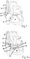
- An exemplary methodbegins by percutaneously accessing the tricuspid annulus (3) from a suitable venous access site.
- the venous access siteis located near the jugular vein, superiorly, from the femoral vein, inferiorly, or from other suitable sites.
- a suitable guide (12)is directed into the internal jugular vein, extends through the right brachiocephalic vein, the superior vena cava (6), and reaches the right atrium (8).
- the distal end (10) of the guide (12)remains inside the right atrium (8).
- the proximal end (not shown) of the guide (12)remains outside of the body.
- the guide (12)could have a general straight profile, In another embodiment, the guide (12) could have a curved distal portion. In some embodiments, the distal portion of the guide (12) could have a pre-set fixed curved. In another embodiment, the distal portion of the guide (12) could be deflectable curved section controlled by a clinician from outside of the body.
- the guide (12)has an axial lumen (14) extending from its proximal end through its entire length to its distal end (10).
- This axial lumen (14) of the guide (2)serves as a conduit, allowing one or more catheters to be slidably disposed within and providing access to the right heart chambers.
- the guide (12)remains in place as illustrated in FIG. 1 during the entire procedure.
- the guide (12)is removed, for example, during the procedure when other suitable means, such as a wire, maintains such a percutaneous access.
- the guide (12)is a 4 mm (12 French (F)) sheath.
- the guide (12)is a single lumen sheath that can accommodate all subsequent catheters to slide therein.
- the guide (12)is a multi-lumen sheath. It will be appreciated by persons of ordinary skill in the art that the size and the exact configuration of the guide (12) is not limited to what is disclosed herein.
- a percutaneous repair of the tricuspid valve (2)starts with identifying and obtaining an access to a first location on the tricuspid annulus (3).
- FIGs. 2-6illustrate some exemplary methods where a wire gains an access to the tricuspid valve (2) from the right ventricle (4) and is advanced across the tricuspid annulus (3) into the right atrium (8).
- the distal end of the wireextends from the venous access site through the lumen (14) of the guide (12), reaches the right atrium (8), extends distally through the tricuspid valve (2), reaches the right ventricle (4), advances across the tricuspid valve (2) annulus, and extends proximally out of the body through the lumen (1) of the guide (12).
- both ends of the wireare outside of the body.
- FIG. 2aillustrates an embodiment where a wire delivery catheter (20) is directed into the right ventricle (4).
- a wire delivery catheteris inserted (20) from the proximal end of the guide (12) through the lumen (14) of the guide (12) and reaches the right atrium (8).
- the wire delivery catheter (20)is extended further distally through the tricuspid valve (2) and reaches the right ventricle (4).
- the distal end portion (22) of the wire delivery catheter (20)bends radially away from the longitudinal axis of the wire delivery catheter (20), assuming a curved profile.
- the curved profile of the distal end portion (22) of the wire delivery catheter (20)is in the shape of the letter "J", the letter “U,” or any curvature between 90° to 270° as marked as " ⁇ " in FIG. 2a .
- the distal end portion (22) of the wire delivery catheter (20)has a preformed curve, such that as the distal end (24) of the wire delivery catheter leaves the constraint of the guide (12) and enters the right ventricle (4), the distal end portion (22) of the wire delivery catheter (20) resumes its curved profile.
- the wire delivery catheter (20)has a deflectable distal end portion (22), which is actuated to form a curved profile.
- the wire delivery catheter (20)can be extended distally, retracted proximally, or turned axially as shown by the double-headed arrows in FIG. 2a .
- the distal end (24) of the wire delivery catheter (20)is adapted to locate the first location (32) and then make contact with the tricuspid annulus (3) at the right ventricle (4) side.
- the right coronary arteryis approximately parallel to the circumference of the tricuspid valve (2).
- the anterior and septal leafletslie approximately to the proximal half of the right coronary artery.
- the posterior leaflet of the tricuspidlies approximately to the distal half of the right coronary artery and between the middle of the right coronary artery and the transition of the distal right coronary artery to the posterior descending artery.
- the middle of the right coronary arterylies approximately next to the commissure of the anterior and posterior leaflets.
- the transition of the distal right coronary artery to the posterior descending artery, or the proximal posterior descending arterylies approximately next to the commissure of the septal and posterior leaflets.
- a first location (32)is identified by injecting a contrast dye inside the right coronary artery and the distal posterior descending artery.
- a locationcan be identified by advancing a radiopaque wire through the right coronary artery to the posterior descending artery.
- the contrast dye and/or the radiopaque wirerenders the right coronary artery visible under radiographic imaging equipment such as X-ray, magnetic resonance, ultrasound, fluoroscope, or other imaging techniques.
- a cliniciansteers the wire delivery catheter so that, as shown in FIG. 2b , the distal end (24) of the wire delivery catheter (20) aligns at the tricuspid annulus (3), extends toward the right atrium (8), and contacts the tricuspid annuius (3) at the first location (32).
- the first location (32)is at or near the commissure of the septal and posterior leaflets.
- the first location (32)is at or near the commissure of the anterior and posterior leaflets.
- Other locations along the tricuspid annulus (3)can also be used as a first location.
- FIG. 3aillustrates that a capture device (40) not falling under the scope of the present invention is advanced distally through the guide (12) and into the right atrium (8).
- a capture device (40)includes a sheath (42) and a capture basket (44).
- a capture devicessuch as the one illustrated in FIG. 3a , includes a capture basket (44) having an array of shape memory wire mesh on the distal end (48) of a rod (46).
- the capture basket (44)has a radially expanded basket-like profile for capturing the wire as described below and an elongated profile when being constrained within the sheath (42),
- the capture basket (42) as shown in FIG. 3ais adapted to slide through the axial lumen (41) of the sheath (42), be pushed out of the distal end (43) of the sheath (42), and be retracted back from the distal end (43) of the sheath (42).
- the capture basket (44)can be used without the sheath (42), but with the guide (12) alone. Thus what has been described herein should not be viewed as limiting. Additionally, one skilled in the art should understand that although an example of the capture device has been described in detail herein, other capture device available in the art can also be used for the same purpose to capture the wire. For example a gooseneck snare mechanism can be used.
- the snare catheteris constructed of Nitinol cable and with a snare loop. The pre-formed snare loop can be introduced through catheters without risk of snare deformation because of the snare's super-elastic construction. The snare loop is used to capture the distal end of the wire.
- a capture device (40) having a capture basket (44) constrained to its elongated profile within the sheath (42)is directed through the lumen (14) of the guide (12).
- the capture device (40)extends through a separate lumen from the one used by the wire delivery catheter (20).
- the capture device (40)extends side-by-side with the wire delivery catheter (20) through the same lumen of the guide.
- the capture basket (44)is further pushed distally outside of the sheath (42) and, being free from the constraint of the sheath (42), the capture basket (44) deploys.
- the deployed capture basket (44)can at least partially fill the volume of the right atrium (8).
- FIG. 3billustrates the capture device (50) according to the invention.
- the capture device (50)includes a capture basket (52) at the distal end (54) of an elongated body (56).
- this capture device (50)is adapted to slide over the wire delivery catheter (20), through the lumen (14) of the guide (12), and be pushed out of the distal end (10) of the guide (12). As the capture device (50) extends outside of the distal end (10) of the guide (12), it resumes its expanded profile. As the capture device (50) is retracted into the lumen (14) of the guide (12), it collapses into its elongated profile.
- the movement of the capture device (50)is independent of the movement of the wire delivery catheter (20). According to other embodiments, the movement of the capture device (50) is dependent to the movement of the wire delivery catheter (20) such that.
- the capture basket (52)is extended outside of the guide (12) and fully deployed inside the right atrium (8). Although certain features of the capture basket (52) are shown in FIGs. 3a and 3b , one skilled in the art would understand that other capture devices can also be used.
- a capture deviceincludes a sheath with an expandable distal portion or a snare.
- a sheathwith an expandable distal portion or a snare.
- One skilled in the artwould understand that other types of suitable capture devices can also be used here. Thus what is disclosed herein and in FIGs. 3a-3b should not be considered as limiting.
- a cliniciancan extend a wire (60a) across the tricuspid annulus (3).
- a wireis introduced through the wire delivery catheter (20).
- the wire (60a)tracks through the axial lumen (26) of the delivery catheter (20), extends distally from its proximal end, contacts the tricuspid annulus (3), further extends distally, crosses the annulus (3) from the right ventricle (4) side, enters into the right atrium (8), and enters the space filled by the capture basket (44, 52).
- the wireis captured by the capture basket.
- the wire (60a)has a piercing tip which allows it to perforate the annulus (3).
- the wire (60a)has a radio frequency (RF) energy delivery tip to assist its crossing of the tricuspid annulus (3).
- RF energy device(not shown) is coupled to the wire.
- the wire delivery catheter (20)also includes an extendable needle (28) that is capable of piercing the tricuspid annulus (3).
- the wire (60a)tracks through the lumen (26) of the such wire delivery catheter (20), extends through the aperture created by the extendable needle (28) of the catheter (20), reaches into the right atrium (8), and enters into the space filled by the capture basket (44, 52). In some embodiments, the wire is captured by the capture basket (44, 52).
- One skilled in the artwould understand that other methods and devices can also be used to access the right atrium (8), Thus, the particular examples described herein should be not viewed as limiting to the scope of the present teachings.
- the distal portion of the wire (60a)is designed to deflect or curl back to prevent inadvertent tissue damage.
- the ability to deflect or curlcan be achieved by the geometrical construct of the wire (60a), such as a flexible distal portion (62), by the physical property of the material used in making the wire (60a), or by the shape memory property of the material used in making the wire (60a).
- a flexible distal portion62
- the physical property of the material used in making the wire (60a)or by the shape memory property of the material used in making the wire (60a).
- the wireenters the right atrium (8) and the space filled by the deployed capture basket (44, 52), it is captured by the capture basket (44, 52) of the capture device (40, 50).
- the capture basket (44, 52)collapses onto the wire (60a).
- the capture device (40, 50)pulls the wire (60a) proximally through the lumen (14) of the guide (12) and out of the body.
- a clinicianfurther retracts the capture device (40), including the sheath (42) and the capture basket (55) as shown in FIG. 3a or including the elongated member (56) with the capture basket (52) as shown in FIG. 3b , proximally through the lumen (14) of the guide (12) outside of the body.
- the clinicianpulls the wire (60a) to the outside of the body.
- the wire (60a)maintains an access across the tricuspid annulus (3) at the first location (32) and facilitates the deployment of a tissue anchor (310a) as detailed below.
- FIGS. 7-9illustrate some embodiments where the wire (160a) extends from the right atrium (8) across the tricuspid annulus (3) into the right ventricle (4) with the proximal end of the wire (160a) outside of the body and the distal end (162) of the wire (160a) inside the right ventricle.
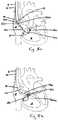
- FIGS. 7a-7cillustrate various examples where the wire delivery catheter (120) is steered by a locating catheter (100) and positioned against the tricuspid annulus (3) inside the right atrium (8).
- the locating catheter (100)extends distally through the lumen (14) of the guide (12) into the right ventricle (4).
- the locating catheter (100)enters into the right ventricle in a similar manner as the wire delivery catheter (20) described in accordance with FIGS. 2a and 2b .
- the locating catheter (100)is positioned against the tricuspid annulus (3) at the first location (32) inside the right ventricle (4),
- the construct of the locating catheter (100)is similar to the wire delivery catheter (20) described above.
- the locating catheterhas a preformed curved distal end portion (102).
- the locating catheteris capable of extending distally and retracting proximally as indicated by the straight double-headed arrows in the FIG. 7a .
- the locating catheteris adapted to turn axially as indicated by the curved double-headed arrows in the FIG. 7a .
- the locating catheter (100)has a magnet (106) at its distal end (104).
- a wire delivery catheter (120)is advanced distally through the lumen (14) of the guide (12), reaching inside the right atrium (8) and approaching the tricuspid annulus (3).
- the distal end (124) of the wire delivery catheter (120)includes a magnet (126).
- the magnets (106, 126) on both the locating catheter (100) and the wire delivery catheter (120)have the opposite polarities.
- the magnet in the distal end of the delivery catheteris attracted by the magnet (106) on the distal end (104) of the locating catheter (100).
- the magnets (106, 126)lock up, the tricuspid annulus (3) is sandwiched between the distal ends (124, 102) of the two catheters as illustrated in FIG. 7b .
- a wire (160a)is then advanced from the right atrium (8) across the tricuspid annulus (3) into the right ventricle (4).
- the wire (160a)tracks along the axial lumen (122a) of the wire delivery catheter (120) and, upon crossing the tricuspid annulus (3), enters the axial lumen (108) of the locating catheter (100).
- the distal end (162) of the wire (160a)remains inside the right ventricle (4).
- FIG. 7cthe wire (160a) tracks along the axial lumen (122a) of the wire delivery catheter (120) and, upon crossing the tricuspid annulus (3), enters the axial lumen (108) of the locating catheter (100).
- the distal end (162) of the wire (160a)remains inside the right ventricle (4).
- the wire (160a)tracks along a side or off-centered axial lumen (122b) of the wire delivery catheter (120) and, upon crossing the tricuspid annulus (3), the distal end (162) of the wire (160a) enters the right ventricle (4).
- the wire delivery catheter (120)also has a deflectable distal end portion (128), which allows this distal end portion (128) deflect radially when the magnet (126) at the distal end (124) of the wire delivery catheter (120) is drawn to the location (32) by the magnet (106) at the distal end (104) of the locating catheter (100), as shown in FIG. 7b .
- the wire delivery catheter (120)can be extended distally and retracted proximally or turned axially, as indicated by the double-headed arrows.
- the design or configuration of the wire (160a)is similar to what is described herein in according with FIGs. 4a and 4b .
- FIGS. 8a and 8billustrate yet other examples where a wire delivery catheter (220) is guided by a locating device (210).
- the wire delivery catheter (220)has two axial lumens (222, 224), one for a wire (260a) and the other for a locating device (210).
- the wire delivery catheter (220)enters the right atrium (8) through the lumen (14) of the guide (12). While maintaining the position of the wire delivery catheter (220) inside the right atrium (8), a clinician can extend the locating device (10) distally through the tricuspid valve (2) into the right ventricle (4) in a similar manner with respect to the wire delivery catheter (20) as described herein in accordance with FIGs. 2a and 2b .
- the locating device (210)can have a curved distal portion (212), either preformed or actuated by a clinician, can be extended distally and retracted proximal ly, or be turned axially as indicated by the double-headed arrows in the FIG. 8a .
- the distal end (214) of the locating device (210)Upon entering the right ventricle (4), the distal end (214) of the locating device (210) is positioned at the first location (32) following the methods described herein in accordance with FIGS. 2a-2b , as well as FIG. 7a . Maintaining the position of the locating device (210) steady, the wire delivery catheter (220) is pushed distally toward the tricuspid annulus (3) so that the annulus (3) is sandwiched between the catheter (220) and the locating device (210), as shown in FIG. 8b . A wire (260a) is advanced distally from the wire lumen (224) across the tricuspid annulus (3) and into the right ventricle (4), as shown in FIG. 8b .
- the distal end (214) of the locating device (210)has openings or slots.
- the wire (260a)advances across the tricuspid annulus (3), it enters the openings or slots in the distal end (214) of the locating device (210).
- the distal end (214) of the locating device (210)is configured that when a clinician retracts the locating device (210) proximally, he/she would not disturb the wire (260a).
- the design and configuration of the wire (260a)is similar to what is described herein according to FIGS. 4a and 4b .
- FIGS. 8a and 8bonly illustrate certain aspects and that they should not be viewed as limiting.
- FIG. 9illustrates that the wire (160, 260) extends distally from a venous access site, tracks along the lumen of the wire delivery catheter (120, 220), enters into the right atrium (8), crosses the tricuspid annulus (3), and reaches the right ventricle (4).
- the proximal end of the wire (160, 260)remains outside of the body and is controlled by a clinician.
- the distal end (162, 262) of the wire (160, 260)remains inside the right ventricle (4).
- the wire (160, 260)has a piercing tip which allows it to perforate the tricuspid annulus (3) or has a radio frequency energy delivery tip which delivers a radio frequency energy to the annulus tissue to perforate the tricuspid annulus (3).
- the distal portion of the wireis designed to deflect or curl back to prevent inadvertent tissue damage, as shown in FIG. 9 .
- a tissue anchor (310a)is deployed at a location.
- a first tissue anchor delivery catheter (300)is tracked along the wire (60a, 160a, 260a), across the tricuspid annulus (3), and into the right ventricle (4).
- the tissue anchor delivery catheter (300)is used to deliver a tissue anchor (310a) to the tricuspid annulus (3).
- a tissue anchorcomprises a plurality of discrete, flat, or flexible anchor elements (312) coupled with a flexible tensile member (314).
- the anchor elements (312)can be made from a surgical grade fabric material (e.g., a polyester material such as DACRON), in some instances, designed to promote tissue in-growth so that the anchors (310a) become at least in part encased in tissue over-time.
- the anchor elements (312)are coupled to a tensile member (314), in this example, a suture, by threading the suture distally through the anchor elements (312) and proximally through the anchor elements (312).
- a slip knot or another type of locking mechanismis formed so that when a proximal end portion of the tensile member (314) is pulled, all of the anchor elements (312) will be drawn together. This leaves a long "tail" of the suture leading from the anchor to the venous access site and the long "tail” can be used for subsequent tensioning and plication, as described herein.
- tissue anchor310) and a tissue anchor delivery catheter (300) described in conjunction with the drawings of the present teachings have some similarities to those in United States Patent Application 2009/0076547, filed on November 19, 2008 , entitled Tissue Anchor and Anchoring System, United States Patent Application 2007/0010857, filed on July 5, 2005 , entitled Tissue Anchor, Anchoring System and Methods of Using the Same, United States Patent Application Serial No. 2014/0243859, filed on February 26, 2013 , entitled Tissue Anchor and Anchoring System.
- suitable tissue anchorsinclude, but are not limited to, tissue fasteners, tissue pledgets, or tissue staples etc.
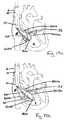
- FIGS. 11 -12illustrate an exemplary delivery and deployment of a first tissue anchor (310a) across the tricuspid annulus (3).
- FIGs. 11a and 12aillustrate the process of exposing of the distal portion (316a) of the tissue anchor (310a) and
- FIGs. 11b and 12billustrate the process of exposing the proximal portion (318a) of the tissue anchor (310a), where the tissue anchor tracks along the wire (60a, 160a, 260a) at the location (32) according to the embodiments described in FIGs. 2-9 .
- FIGs. 11c and 12cillustrate an exemplary deployment of the tissue anchor (3] 0a) positioned at the location (32) according to the embodiment described in association with FIGs. 2-9 , where the tissue anchor tracks along the wire (60a, 160a, 260a).
- a tissue anchor delivery catheter (300) holding a tissue anchor (310a) inside its longitudinal lumen (302)tracks along the wire (60a, 160a, 260a), across the tricuspid annulus (3), and into the right ventricle (4).
- the tissue anchor (310a)is partially pushed distally outside of the distal end (304) of the tissue anchor delivery catheter (300). Once the distal portion (316a) of the tissue anchor (310a) or a sufficient amount of the anchor elements (312, shown in FIG.
- a clinicianstops pushing the tissue anchor (310a) distally and retracts the tissue anchor delivery catheter (300) proximally so that the distal end (304) of the tissue anchor delivery catheter (300) moves proximally across the annulus (3) and back into the right atrium (8).
- the clinicianthen exposes the proximal portion (318a) of the tissue anchor (310a) or the remainder of the anchor elements (312) of the tissue anchor (310a) within the right ventricle (4) by further retracting the tissue anchor delivery catheter (300) proximally as shown in FIGs. 11b and 12b .
- the clinicianpulls the proximal end of the tensile member (314) such that the anchor elements (312) of the tissue anchor (310a) are drawn together against the opposite sides of the tricuspid annulus (3), thereby securing the first tissue anchor (310a) to the tricuspid annulus (3).
- the clinicianpulls the proximal end of the tensile member (314) such that the anchor elements (312) of the tissue anchor (310a) are drawn together against the opposite sides of the tricuspid annulus (3), thereby securing the first tissue anchor (310a) to the tricuspid annulus (3).
- the first tissue anchor (310a)is deployed across the tricuspid annulus (3) at the first location (32) with the distal portion (316) of the tissue anchor (310a) placed against the atrial side of the tricuspid annulus (3), the proximal portion (318) of the tissue anchor (10a) placed against the ventricle side of the tricuspid annulus (3), and the tensile member (3 14) of the first tissue anchor (310a) extending proximally through the lumen (302) of the tissue anchor delivery catheter (300) to the outside of the body.
- the wire (60a, 160a, 260a) that marks the first location (32) and maintains the annulus access during the deployment of the first tissue anchor (310a)is then withdrawn proximally outside of the body, while the proximal end of the tensile member (314) is controlled by the clinician from outside of the body.
- proximal and distal portion (316a) of the tissue anchors (310a)are deployed/cinched simultaneously
- distal portion (316a) of the tissue anchors (310a)can be deployed/cinched right after being exposed inside the right ventricle (4) and before the tissue anchor delivery catheter (300) being retracted back into the right atrium (8).
- the proximal portion (318a)is then exposed within the right ventricle (4) and further deployed/cinched against the tricuspid annulus (3).
- specific examples disclosed hereinshould not be viewed as limiting. Similar tissue anchor deployment technique known in the field could also be incorporated herein.
- FIGs. 13-14illustrate several exemplary deployment of a second tissue anchor (310b) at a second location (30) across the tricuspid annulus (3).
- a clinicianuses the similar steps to position a wire delivery catheter (20) against the tricuspid annulus (3) from inside the right ventricle (4) at the second location (30).
- the positioning of the wire delivery catheter against the tricuspid annulusincludes extending, retracting, turning, or otherwise manipulating the wire delivery catheter (20) to the second location (30) similar to the methods described herein or known to those with ordinary skill in the art.
- one end of the second wire (60b)is advanced across the tricuspid annulus (3), captured by the capture basket (44, 52) as illustrated in FIGS.
- a cliniciantakes the similar steps to position the wire delivery catheter (120, 220) against the tricuspid annulus (3) from inside the right atrium (8) at a second location (30). This is done by extending, retracting, turning, or otherwise manipulating a locating catheter (100) or a locating device (210) at the second location (30) through methods similar to those described herein or known to those with ordinary skill in the art. Similar to what is described in accordance with FIGs. 7-9 , the wire delivery catheter (120, 220) is positioned at the second location (30) through magnetic attraction or by the wire delivery catheter design discussed herein. As illustrated in FIG.
- a second wire(160b, 260b) is advanced distally across the tricuspid annulus (3) and reaches the right ventricle (4) as described herein.
- the resultis illustrated in FIG. 13b , where one end of the wire (160b, 260b) extends distally through the lumen (14) of the guide (12) and reaches the right ventricle (4).
- the distal end of the second wire (160b, 260b)resides inside the right ventricle (4) and the proximal end of the second wire (160b, 260b) resides outside of the body.
- FIGs. 14a and 14billustrate that the second tissue anchor (310b) is deployed across the tricuspid annulus (3) at the second location (30) with the distal portion (316b) of the second tissue anchor (310b) placed against the ventricle side of the annulus (3), the proximal portion (318b) of the tissue anchor (310b) placed against the atrial side of the annulus (3), and the tensile member (314) of the second tissue anchor (310b) extending proximally through the venous access to the outside of the body.
- the second wire (60b, 160b, 260b)can be removed.
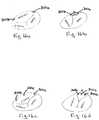
- FIG. 15illustrates an exemplary bicuspidization of a tricuspid valve (2).
- a clinicianapplies tension to one or both of the tensile members (314a, 314b) of the tissue anchors (310a, 310b). This tension pulls two tissue anchors (310a) closer to each other, thereby reducing the circumference of the tricuspid annulus (3).
- This tension, and the reduced distance between the two tissue anchors (310a, b)are maintained by directing a locker member (330) along the tensile members (314a, 314b) towards the tissue anchors (310a, 310b).
- Suitable lockersinclude those well known in the art and those described in U.S.
- FIGS. 16a and 16billustrate an exemplary process of bicuspidization.
- the first tissue anchor (310a)is deployed at a location at or close to the commissure of the posterior and septal leaflets and the second tissue anchor (310b) is deployed at a location at or close to the commissure of the posterior and anterior leaflets, as illustrated in FIG. 16a .
- the posterior annulusis shortened and the posterior leaflet is effectively eliminated, thereby turning the three-leaflet valve into a two-leaflet valve.
- the processis called bicuspidization, as illustrated in FIG. 16b .
- Both the tissue anchors (310a, 310b)are positioned along the posterior annulus.
- at least one tissue anchor (310a)is positioned on the posterior annulus and the other tissue anchor (310b) is placed on the anterior annulus or the septal annulus.
- at least one tissue anchor (310a)is placed at a location at or close to the commissure of the posterior and septal leaflets and the other tissue anchor (310b) is placed at a location between the commissure of the posterior and septal leaflets and the commissure of the posterior and anterior leaflets.
- tissue anchors (10a and 310b)are deployed around the annulus circumferences.
- more than two tissue anchors (310a, 310b)are deployed.
- FIGs. 16c and 16dincludes one tissue anchor (310a) deployed at an location at or close to the commissure of the posterior and septal leaflets, one tissue anchor (310b) deployed at an location at or close to the commissure of the posterior and anterior leaflets, and another tissue anchor (310c) deployed approximately in the middle of the first two.
- FIGS. 16a-16dillustrate certain examples , other configuration and other locations can also be used for placing the tissue anchor (310a).
- tissue anchorscould be implanted along the posterior annulus of the tricuspid valve.
- tissue anchor (310a)or the number of the tissue anchors (310a) deployed should not be viewed as limiting.
- tissue anchorsare illustrated herein, more than three tissue anchors can also be used without departing from the scope of the present teachings.
- Tensionis applied to all tissue anchors and secured by one locker.
- tensionis applied to two of the tissue anchors at a time, for example, as illustrated in FIGS. 16e and 16f .
- Each tissue anchoris deployed sequentially.
- the embodiments described in accordance with FIGS. 2-15allow a clinician to place a wire (60, 160, 260) at the first location (32), followed by deploying a first tissue anchor (310a) over the wire (60, 160, 260), and then manipulate the same wire delivery mechanism to and place the wire at a second location (30), followed by deploying a second tissue anchor (310b) over the wire (60, 160, 260).
- two or more tissue anchorsare deployed simultaneously.
- a multi-lumen translation catheter (400)can be used to place two wires at two locations at the same time.
- a catheter with more than two branchescan be used to place multiple wires at multiple locations at the same time.
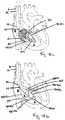
- FIGS. 17-19illustrate the use of a multi-lumen translation catheter (400) to place two wires (460a, 460b) across the tricuspid annulus (3).
- a multi-lumen translation catheter (400)comprises a first catheter member (402a) having a first lumen (404a) for a first wire (460a) and a second catheter member (402b) having a second lumen (404b) for a second wire (460b).
- the first and second wires (460a, 460b)are slidably disposed within the first and second catheter lumens (404a, 404b), respectively.
- a multi-lumen translation catheter (400)is delivered to the right ventricle (4) and positioned against the tricuspid annulus (3) through a wire delivery catheter (20), as illustrated in FIG. 2a . Similar to what is described herein in accordance with FIGS. 2-6 , upon the wire delivery catheter (20) being positioned against the tricuspid annulus (3) from inside the right ventricle (4), the first wire (460a), extending through the lumen (404a) of the first catheter member (402a), is placed across the tricuspid annulus (3). The wire delivery catheter (20) is retracted proximaliy, exposing the second catheter member (402b) of the multi-lumen translation catheter (400), as illustrated in FIG. 18a .
- the second catheter member (402b)expands laterally away from the first catheter member (402a) to a pre-defined distance. Without losing the placement of the first wire (460a), a clinician can turn the multi-lumen translation catheter (400) and/or the wire delivery catheter (20) so that the second catheter member (402b) is positioned at a second location (30), A second wire (460b) is then advanced across the tricuspid annulus (3) following the steps described herein and shown in FIGS. 4a and 4b .
- Both the wires (460a, 460b)is captured by the capture device and the distal ends of the both wires (460a, 460b) are then withdrawn through the lumen (14) of the guide (12) outside of the body.
- two wiresare placed at two locations, which can be used to facilitate the deployment of two tissue anchors (310a), following the steps discussed above and in accordance with FIGS. 11a-11c .
- a multi-lumen translation catheter or device (500)is delivered though the lumen of a locating catheter (100) to the right ventricle (4).
- a first catheter member (502a)is placed at a first location (32), attracting a first wire delivery catheter (510a) and facilitating the placement of a first wire (560a).
- the locating catheter (100)is retracted proximaliy, exposing a second catheter member (502b) of the multi-lumen translation catheter (500) as illustrated in FIG. 19a .
- the second catheter member (502b)expands laterally away from the first catheter member (502a) to a pre-defined distance. Without losing the placement of the first wire delivery catheter (10a), a clinician can turn the multi-lumen translation catheter (500) and/or the locating catheter (100) so that the second catheter member (502b) is positioned at a second location (30). The second catheter member (502b) attracts the second wire delivery catheter (510b) and facilitates the placement of the second wire (560b) across the tricuspid annulus (3) as shown in FIG. 19b .
- the multi-lumen translation catheteris placed at two locations first and two wires are placed across the tricuspid annulus simultaneously or sequentially.
- a first catheter member of a multi-lumen translation catheteris positioned at a first location first and a first wire is placed across the tricuspid annulus;
- a second catheter member of the multi-lumen translation catheteris positioned at a second location and a second wire is placed across the tricuspid annulus.
- FIGS. 18b and 19btwo wires are placed at two locations, followed by the deployment of two tissue anchors according to the steps or steps similar with those discussed herein and in accordance with FIGS. 11-16 .
- tricuspid annuluscan be plicated by a chain of tissue anchors. Two or more tissue anchors are connected together by a tensile member. Plication happens by pulling said tensile member and thereby drawing all tissue anchors together.
- FIGS. 20A-Cillustrates that a single tensile member may be used to deploy, fasten and draw together at least two separate tissue anchors.
- first and second tissue anchors (10, 612)are deployed at spaced apart locations along the tricuspid valve annulus (3).
- Each tissue anchors (610, 612)includes an elongate strip (606a, 606b) of flexible material, such as fabric or other material as described above, as well as a single tensile member (608) extending through each of the elongate strips (606a, 606b).
- the free end (614) of the tensile member (608)is pulled thereby securely fastening the first tissue anchor (610) as shown in FIG. 20A and subsequently securely fastening the second tissue anchor (612) to the annulus (3) tissue as shown in FIG. 20B .
- the tissue anchors (610, 612)will be drawn together to plicate the tissue therebetween as shown in FIG. 20C .
- a locker member (616)may then be used to lock in the desired amount of plication by lock the free end (614) of the tensile member (608) as shown in FIG. 20C .
- the free end (614) of the tensile member (608)may then be cut to appropriate length.
- more than two tissue anchorscould be used with this teaching.
- FIGS. 21A-21Cillustrates that tricuspid annulus is plicated by a chain of tissue anchors. Similar to above described methods, two tissue anchors (710,712) are secured to tricuspid annulus (3), each with a tensile member (706, 708) extending proximally.
- FIG. 21 Aillustrates that the tensile members (706, 708) extend through a first locker member (702).
- Suitable locker memberscan include those described in U.S. Patent Application 2007/0080188 and U.S. Patent Application 2007/0276437 , or other suitable lockers known within the art.
- the first locker member (702)can include a locker body having a passageway through which the tensile members (706, 708) extend.
- a slidable membercan be positioned within the passageway, which can be moved from a latent condition to an activated condition to prevent the tensile members (706, 708) from moving relative to the locker body. Both tensile members (706, 708) are pulled proximally by the clinician. Upon plicating annulus tissue between the first tissue anchor (710) and the second tissue anchor 712, the tensile members (706, 708) are locked by the first locker member (702) to preserve the plications created by tensioning as illustrated in FIG. 21B . A suture cutter is then advanced along tensile members (706, 708) to just proximal to the first locker member (702).
- Tensile member (708) from the second tissue anchor (712)is cut while the tensile member (706) from the first tissue anchor (710) remains intact.
- tensile member (706) from the second tissue anchor (710)is cut while the tensile member (708) from the first tissue anchor (712) remains intact.
- a cliniciancan then repeat method of tissue plication described above and extend the first tensile member (706) from the first tissue anchor (710) to a second locker member (704).
- a third tissue anchor (714)is further deployed across the posterior annulus (3) with a third tensile member (716) extending proximally.
- the tensile members (706, 716)are locked by the second locker member (704) to preserve the plication created by tensioning as illustrated in FIG. 21C .
- the second locker member (704)can be the same as the first locker member (702), or if desired, a different suitable locker can be used.
- tensionis applied to the tensile members (706, 716), the tissue of the posterior annulus (3) is further plicated. This plication further reduces the size of the tricuspid valve orifice.
- a suture cuttercan then be advanced to cut the tensile members (706, 716) just proximal to the second locker member (704). However, if plication is not complete such that the posterior, anterior and septal leaflets do not coapt, then additional tissue anchors can be advanced to the annular tissue. Accordingly, at least one of the tensile members (706, 716) remains intact to be tensioned with a subsequently positioned tissue anchor.
- a radioopaque marker or textured surfacecan be used to make the device visible by using radiographic imaging equipment such as an X-ray, magnetic resonance, ultrasound or other imaging technique.
- a marker disclosed hereinmay be applied to any part of the guide, catheter, or devices disclosed in present teachings.
- a radioopaque markercan be sewed, adhered, swaged riveted, or otherwise placed and secured on the guide, catheter, and/or devices,
- the radioopaque markermay be made from a material selected from tantalum, tungsten, platinum, irridium, gold, an alloy thereof, or another material known to those with ordinary skill in the art.
- the radioopaque markercan also be made from cobalt, fluorione, or another paramagnetic material, or another MR visible material known to those with ordinary skill in the arts. Additionally, a contrast media injected into the atrium, ventricle, or artery may also be used to confirm the positioning under a fluoroscope.
Landscapes
- Health & Medical Sciences (AREA)
- Surgery (AREA)
- Life Sciences & Earth Sciences (AREA)
- Medical Informatics (AREA)
- Nuclear Medicine, Radiotherapy & Molecular Imaging (AREA)
- Engineering & Computer Science (AREA)
- Biomedical Technology (AREA)
- Heart & Thoracic Surgery (AREA)
- Rheumatology (AREA)
- Molecular Biology (AREA)
- Animal Behavior & Ethology (AREA)
- General Health & Medical Sciences (AREA)
- Public Health (AREA)
- Veterinary Medicine (AREA)
- Prostheses (AREA)
- Surgical Instruments (AREA)
Description
- The present teachings generally relate to percutaneous valve repair. Some embodiments of the present teachings relate to percutaneous tricuspid valve repair.
- Tricuspid valve diseases relate to conditions in which the valve between the two right heart chambers (i.e., the right ventricle and the right atrium) doesn't function properly and they often occur with other heart valve problems. An example of tricuspid valve diseases is tricuspid valve regurgitation, where the tricuspid valve doesn't close properly and blood flows back into the right atrium. Another example is tricuspid valve stenosis where the tricuspid valve is narrowed, which reduces the amount of blood flowing into the right ventricle. Yet another example is tricuspid atresia, a congenital heart disease, where a solid wall of tissues blocks the blood from flowing between the two right heart chambers. Yet another example is the Ebstein's anomaly where a malformed tricuspid valve situates at a position lower than the normal in the right ventricle, causing blood to flow back into the right atrium. There are other tricuspid valve diseases generally known to a person with ordinary skill in the art and these tricuspid valve diseases are also included in the present teachings.
- A tricuspid valve disease can be corrected by an annuloplasty ring. In some instances, this device is preferred for surgically repairing a defect tricuspid valve. An annuloplasty ring is an anatomically-correct three-dimensional (3D) ring and can flexibly conform to the heart valve opening. This ring is implanted into a defect tricuspid valve and reduces the valve opening. Properly implanted, an annuloplasty ring allows the valve to open and close properly.
- Tricuspid valve repair surgery can be done in one of two ways: a minimally invasive surgery or an open-heart surgery. A minimally invasive method involves making a small upper or lower chest incision and inserting valve repairing system/device percutaneously. After the valve is repaired, the incision is closed with dissolving sutures. Advantages of a
minimally invasive approach include a shorter recovery time, less post-operation pain, and earlier return to work and normal daily activities. Devices for minimally invasive methods are disclosed inUS2010/292785 ,WO2012/004679 andWO2012/178115 . - The present invention is defined by the features of the appended independent claim. Preferred embodiments are given in the dependent claims. One aspect of the present teachings provides a method for percutaneously reducing the circumference of a tricuspid annulus. This method includes a number of steps, the sequence of which can be changed and each of which can be omitted or modified without the method falling outside the scope of the present teachings. An exemplary step includes positioning a wire delivery catheter through the tricuspid valve into the right ventricle. Another exemplary step includes contacting a distal end of the wire delivery catheter with the tricuspid annulus inside the right ventricle at a first location. Another exemplary step includes advancing one end of a wire from the right ventricle across the tricuspid annulus to the right atrium at the first location, where the wire tracks through an axial lumen of the wire delivery catheter. Another exemplary step includes capturing the end of the wire with a capture device deployed inside the right atrium. Another exemplary step includes retracting the capture device proximally to bring the end of the wire outside of the body. Another exemplary step includes tracking a first tissue anchor delivery catheter over the wire and extending the first tissue anchor delivery catheter across the tricuspid annulus so that a distal end of the first tissue anchor delivery catheter resides inside the right ventricle, Another exemplary step includes deploying a first tissue anchor with a distal portion of the tissue anchor positioning against the tricuspid annulus from inside the right ventricle and a proximal portion of the tissue anchor positioning against the tricuspid annulus from inside the right atrium. Another exemplary step includes retracting the end of the wire back into the axial lumen of the wire delivery catheter.
- Another exemplary step includes positioning the wire delivery catheter with the distal end of the wire delivery catheter contacting the tricuspid annulus inside the right ventricle at a second location. Another exemplary step includes advancing the end of the wire from the right ventricle across the tricuspid annulus to the right atrium. Another exemplary step includes capturing the end of the wire with a capture device deployed inside the right atrium. Another exemplary step includes retracting the capture device proximally and thereby extending the end of the wire outside of the body. Another exemplary step includes tracking a second tissue anchor delivery catheter over the wire. Another exemplary step includes extending the second tissue anchor delivery catheter across the tricuspid annulus at the second location so that a distal end of the second tissue anchor delivery catheter resides
inside the right ventricle. Another exemplary step includes deploying a second tissue anchor with a distal portion of the tissue anchor positioning against the tricuspid annulus from inside the right ventricle and a proximal portion of the tissue anchor positioning against the tricuspid annulus from inside the right atrium. Another exemplary step includes reducing the distance between the first and second tissue anchors. - In other aspects, a method for percutaneously reducing the circumference of a tricuspid annulus includes a number of other steps, the sequence of which can be changed and each of which can be omitted or modified without the method falling outside the scope of the present teachings. An exemplary step includes positioning a locating catheter through the tricuspid valve into the right ventricle. Another exemplary step includes contacting a distal end of the locating catheter with the tricuspid annulus inside the right ventricle at a first location. Another exemplary step includes advancing a wire delivery catheter into the right atrium with a distal end of the wire delivery catheter opposing the distal end of the locating catheter and contacting the tricuspid annulus inside the right atrium at the first location. Another exemplary step includes advancing a distal end of a wire from the right atrium across the tricuspid annulus to the right ventricle at the first location, wherein the wire tracks through an axial lumen of the wire delivery catheter. Another exemplary step includes tracking a first tissue anchor delivery catheter over the wire. Another exemplary step includes crossing the tricuspid annulus with a distal end of the first tissue anchor delivery catheter inside the right ventricle. Another exemplary step includes deploying a first tissue anchor with a distal portion of the tissue anchor positioning against the tricuspid annulus from inside the right ventricle and a proximal portion of the tissue anchor positioning against the tricuspid annulus from inside the right atrium. Another exemplary step includes retracting the distal end of the wire back into the axial lumen of the wire delivery catheter. Another exemplary step includes positioning the locating catheter with the distal end of the locating catheter contacting the tricuspid annulus inside the right ventricle at a second location. Another exemplary step includes positioning the wire delivery catheter into the right atrium with the distal end of the wire delivery catheter opposite to the distal end of the locating catheter and contacting the tricuspid annulus inside the right atrium at the second location. Another exemplary step includes advancing the distal end of the wire from the right atrium across the tricuspid annulus to the right ventricle. Another exemplary step includes tracking a second tissue anchor delivery catheter over the wire and crossing the tricuspid annulus at the second location with a distal end of the second tissue anchor delivery catheter inside the right ventricle. Another exemplary step includes deploying a second tissue anchor
with a distal portion of the tissue anchor positioning against the tricuspid annulus from inside the right ventricle and a proximal portion of the tissue anchor positioned against the tricuspid annulus from inside the right atrium. Another exemplary step includes reducing the distance between the first and second tissue anchors. - In other aspects, a method for percutaneously reducing the circumference of a tricuspid annulus includes a number of steps, the sequence of which can be changed and each of which can be omitted or modified without the method falling outside the scope of the present teachings. An exemplary step includes positioning a wire delivery catheter through the tricuspid valve into the right ventricle, wherein a multi-lumen translation catheter is slidably disposed within a lumen of the wire delivery catheter, a first wire is slidably disposed within a first catheter member of the multi-lumen translation catheter, a second wire is slidably disposed within a second catheter member of the multi-lumen translation catheter. Another exemplary step includes positioning a distal end of the first catheter member at a first location. Another exemplary step includes advancing one end of the first wire from the right ventricle across the tricuspid annulus to the right atrium at the first location. Another exemplary step includes expanding the second catheter member of the multi-lumen translation catheter. Another exemplary step includes positioning a distal end of the second catheter member against the tricuspid annulus at a second location. Another exemplary step includes advancing one end of the second wire from the tight ventricle across the tricuspid annulus to the right atrium at the second location. Another exemplary step includes capturing the ends of the first and second wires with a capture device. Another exemplary step includes retracting the capture device proximally and extending the ends of the first and second wires outside of the body. Another exemplary step includes tracking a first tissue anchor delivery catheter over the first wire and a second tissue anchor delivery catheter over the second wire. Another exemplary step includes crossing the tricuspid annulus with distal ends of the first and second tissue anchor delivery catheters inside the right ventricle. Another exemplary step includes deploying the first and second tissue anchors with distal portions of the first and second tissue anchors positioning against the tricuspid annulus from inside the right ventricle and proximal portions of the first and second tissue anchors positioning against the tricuspid annulus from inside the right atrium. Another exemplary step includes reducing the distance between the first and second tissue anchors.
- In other aspects, a method for percutaneously reducing the circumference of a tricuspid annulus includes a number of steps, the sequence of which can be changed and each of which can be omitted or modified without the method falling outside of the present teachings. An exemplary step includes positioning a locating catheter through the tricuspid valve into the right ventricle, wherein a multi-lumen translation catheter is slidably disposed within a lumen of the locating catheter and the multi-lumen translation catheter has a first catheter member and a second catheter member. Another exemplary step includes positioning a distal end of the first catheter member at a first location. Another exemplary step includes expanding the second catheter member of the multi-lumen translation catheter and positioning a distal end of the second catheter member against the tricuspid annulus at a second location. Another exemplary step includes advancing first and second wire delivery catheters into the right atrium with distal ends of the first and second wire delivery catheters positioned opposite to the distal ends of the first and second catheter member. Another exemplary step includes contacting the tricuspid annulus inside the right atrium at the first and second locations. Another exemplary step includes advancing distal ends of first and second wires from the right atrium across the tricuspid annulus to the right ventricle at the first and second locations. Another exemplary step includes tracking the first and second tissue anchor delivery catheters over the first and second wires and crossing the tricuspid annulus with distal ends of the first and second tissue anchor delivery catheters inside the right ventricle. Another exemplary step includes deploying the first and second tissue anchors with distal portions of the first and second tissue anchors positioned against the tricuspid annulus from inside the right ventricle and proximal portions of the first and second tissue anchors positioned against the tricuspid annulus from inside the right atrium. Another exemplary step includes reducing the distance between the first and second tissue anchors.
FIG. 1 is a perspective view of an exemplary guide percutaneously inserted into the right atrium;FIGS. 2a-2b are perspective views of an exemplary wire delivery catheter inserted into the right ventricle;FIGS. 3a-3b are perspective views of an exemplary capture device deployed inside the right atrium;FIGS. 4a-4b are perspective views of an exemplary wire positioned across the annulus;FIG. 5 is a perspective view of an exemplary wire captured and pulled through the guide;FIG. 6 is a perspective view of an exemplary wire positioned across the annulus;FIGS. 7a-7b are perspective views of an exemplary locating catheter inserted into the right ventricle;FIGS. 7c-7d are perspective views of an exemplary wire across the annulus;FIGS. 8a-8b are perspective views of an exemplary locating device inserted into the right ventricle;FIG. 9 is a perspective view of an exemplary wire positioned across the annulus;FIG. 10 is a perspective view of an exemplary tissue anchor;FIGS. 11a-11c are perspective views of an exemplary tissue anchor deployed across the tricuspid annulus;FIGS. 12a- 12c are perspective views of an exemplary tissue anchor deployed across the tricuspid annulus;FIGS. 13a- 13b are perspective views of an exemplary method where an exemplary second wire extends across the tricuspid annulus;FIGS. 14a-14b are perspective views of an exemplary second tissue anchor deployed across the tricuspid annulus;FIG. 15 is a perspective view of applying tension to two exemplary tissue anchors deployed across annulus;FIGS. 16a-16f are perspective views of an example of applying tension to multiple exemplary tissue anchors deployed across the tricuspid annulus;FIG. 17 is a perspective view of an exemplary multi-lumen translation catheter;FIGS. 18a-18b are perspective views of an example of placing two exemplary wires across the tricuspid annulus with an exemplary multi-lumen translation catheter;FIGS. 19a- 19b are perspective views of an example of placing two exemplary wires across the tricuspid annulus with an exemplary multi-lumen translation catheter;FIGS. 20a-20c are perspective views of placing multiple tissue anchors across the tricuspid annulus; andFIGS. 21a-21c are perspective views of placing multiple tissue anchors across the tricuspid annulus.- Certain specific details are set forth in the following description and figures to provide an understanding of various embodiments of the present teachings. Those of ordinary skill in the relevant art would understand that they can practice other embodiments of the present teachings without one or more of the details described herein. Thus, it is not the intention of the Applicant(s) to restrict or in any way limit the scope of the appended claims to such details. While various processes are described with reference to steps and sequences in the following disclosure, the steps and sequences of steps should not be taken as required to practice all embodiments of the present teachings.
- As used herein, the term "lumen" means a canal, a duct, or a generally tubular space or cavity in the body of a subject, including a catheter, a hollow needle, a tube, a vein, an artery, a blood vessel, a capillary, an intestine, and the like.
- As used herein, the term "proximal" shall mean close to the operator (less into the body) and "distal" shall mean away from the operator (further into the body). In positioning a medical device inside a patient, "distal" refers to the direction away from a catheter insertion location and "proximal" refers to the direction close to the insertion location.
- As used herein, the term "wire" can be a strand, a cord, a fiber, a yarn, a filament, a cable, a thread, or the like, and these terms may be used interchangeably.
- As used herein, the term "sheath" may also be described as a "catheter" and, thus, these terms can be used interchangeably.
- The following description refers to
FIGS. 1 to 19 . A person with ordinary skill in the art would recognize that the figures and description thereto refer to various embodiments of the present teachings and, unless indicated otherwise by their contexts, do not limit the scope of the attached claims to the figures and/or description thereto. - Unless otherwise specified, all numbers expressing quantities, measurements, and other properties or parameters used in the specification and claims are to be understood as being modified in all instances by the term "about." Accordingly, unless otherwise indicated, it should be understood that the numerical parameters set forth in the following specification and attached claims are approximations. At the very least and not as an attempt to limit the application of the doctrine of equivalents to the scope of the attached claims, numerical parameters should be read in light of the number of reported significant digits and the application of ordinary rounding techniques.
- The present teachings relate to devices for treating a tricuspid regurgitation according to the appended claims. An aspect of the present teachings provides various embodiments of locating a first location on the tricuspid annulus (3) (as shown in
FIGS. 1 to 19 ). According to some embodiments, the first location is on the posterior annulus approximate to the commissure of the posterior and septal leaflets or to the commissure of the posterior and anterior leaflets. - A further aspect of the present teachings provides various embodiments of placing a wire across the tricuspid annulus (3) at the first location. According to some embodiments, the wire crosses the tricuspid annulus (3) from the right atrium to the right ventricle (4) (as shown in
FIGs. 1 to 19 ). According to some embodiments, a wire of the present teachings crosses the tricuspid annulus (3) from the right ventricle to the right atrium (8) (as shown inFIGs. 1 to 19 ). A further aspect of the present teachings provides various embodiments of deploying a tissue anchor (310a) (as shown, for example, inFIG. 1 1a ) over the wire and across the tricuspid annulus. According to some embodiments, the distal portion of the tissue anchor (310a) is deployed inside the right ventricle (4) and the proximal portion of the tissue anchor (310a) is deployed inside the right atrium (8). According to some embodiments, the distal portion of the tissue anchor (310a) is deployed inside the right atrium (8) and the proximal portion of the tissue anchor (310a) is deployed inside the right ventricle (4). - A further aspect of the present teachings provides various embodiments of locating a second location (30) (as shown, for example, in
FIG. 13a ) on the tricuspid annulus (3), placing a second wire across the tricuspid annulus (3), and then deploying a second tissue anchor (310b) (as shown, for example, inFIG. 14a ) across the tricuspid annulus. - A further aspect of the present teachings provides various embodiments of reducing the circumference of the tricuspid annulus (3). An exemplary method begins by percutaneously accessing the tricuspid annulus (3) from a suitable venous access site. According to some embodiments, the venous access site is located near the jugular vein, superiorly, from the femoral vein, inferiorly, or from other suitable sites.
- As illustrated in
FIG. 1 , a suitable guide (12) is directed into the internal jugular vein, extends through the right brachiocephalic vein, the superior vena cava (6), and reaches the right atrium (8). The distal end (10) of the guide (12) remains inside the right atrium (8). The proximal end (not shown) of the guide (12) remains outside of the body. According to some embodiments, the guide (12) could have a
general straight profile, In another embodiment, the guide (12) could have a curved distal portion. In some embodiments, the distal portion of the guide (12) could have a pre-set fixed curved. In another embodiment, the distal portion of the guide (12) could be deflectable curved section controlled by a clinician from outside of the body. The guide (12) has an axial lumen (14) extending from its proximal end through its entire length to its distal end (10). This axial lumen (14) of the guide (2) serves as a conduit, allowing one or more catheters to be slidably disposed within and providing access to the right heart chambers. According to some embodiments, the guide (12) remains in place as illustrated inFIG. 1 during the entire procedure. According to some embodiments, the guide (12) is removed, for example, during the procedure when other suitable means, such as a wire, maintains such a percutaneous access. According to some embodiments, the guide (12) is a 4 mm (12 French (F)) sheath. According to some embodiments, the guide (12) is a single lumen sheath that can accommodate all subsequent catheters to slide therein. Alternatively, in some embodiments, the guide (12) is a multi-lumen sheath. It will be appreciated by persons of ordinary skill in the art that the size and the exact configuration of the guide (12) is not limited to what is disclosed herein.
A percutaneous repair of the tricuspid valve (2) starts with identifying and obtaining an access to a first location on the tricuspid annulus (3).FIGs. 2-6 illustrate some exemplary methods where a wire gains an access to the tricuspid valve (2) from the right ventricle (4) and is advanced across the tricuspid annulus (3) into the right atrium (8). Upon doing so, the distal end of the wire extends from the venous access site through the lumen (14) of the guide (12), reaches the right atrium (8), extends distally through the tricuspid valve (2), reaches the right ventricle (4), advances across the tricuspid valve (2) annulus, and extends proximally out of the body through the lumen (1) of the guide (12). As a result, both ends of the wire are outside of the body. FIG. 2a illustrates an embodiment where a wire delivery catheter (20) is directed into the right ventricle (4). In one embodiment, a wire delivery catheter is inserted (20) from the proximal end of the guide (12) through the lumen (14) of the guide (12) and reaches the right atrium (8). As shown inFIG. 2a , as the distal end (24) of the wire delivery catheter (20) extends beyond the distal end (10) of the guide (12), the wire delivery catheter (20) is extended further distally through the tricuspid valve (2) and reaches the right ventricle (4). Inside the right ventricle (4), the distal end portion (22) of the wire delivery catheter (20) bends radially away from the longitudinal axis of the wire delivery catheter (20), assuming a curved profile. According to some embodiments, the curved profile of the distal end portion
(22) of the wire delivery catheter (20) is in the shape of the letter "J", the letter "U," or any curvature between 90° to 270° as marked as "Θ" inFIG. 2a . According to some embodiments, the distal end portion (22) of the wire delivery catheter (20) has a preformed curve, such that as the distal end (24) of the wire delivery catheter leaves the constraint of the guide (12) and enters the right ventricle (4), the distal end portion (22) of the wire delivery catheter (20) resumes its curved profile. According to some other embodiments, the wire delivery catheter (20) has a deflectable distal end portion (22), which is actuated to form a curved profile. One skilled in the art would understand that such an actuation can be accomplished by many mechanisms known in the field. According to some embodiments, the wire delivery catheter (20) can be extended distally, retracted proximally, or turned axially as shown by the double- headed arrows inFIG. 2a .- As further illustrated in
FIG. 2b , the distal end (24) of the wire delivery catheter (20) is adapted to locate the first location (32) and then make contact with the tricuspid annulus (3) at the right ventricle (4) side. - Anatomically, the right coronary artery is approximately parallel to the circumference of the tricuspid valve (2). The anterior and septal leaflets lie approximately to the proximal half of the right coronary artery. The posterior leaflet of the tricuspid lies approximately to the distal half of the right coronary artery and between the middle of the right coronary artery and the transition of the distal right coronary artery to the posterior descending artery. The middle of the right coronary artery lies approximately next to the commissure of the anterior and posterior leaflets. The transition of the distal right coronary artery to the posterior descending artery, or the proximal posterior descending artery, lies approximately next to the commissure of the septal and posterior leaflets. One skilled in the art would understand that the anatomy of the heart may vary from a subject to another and the present teachings and the attached claims are not limited to the anatomy of any particular subject.
- For example, a first location (32) is identified by injecting a contrast dye inside the right coronary artery and the distal posterior descending artery. Alternatively, a location can be identified by advancing a radiopaque wire through the right coronary artery to the posterior descending artery. In various embodiments, the contrast dye and/or the radiopaque wire renders the right coronary artery visible under radiographic imaging equipment such as X-ray, magnetic resonance, ultrasound, fluoroscope, or other imaging techniques. By visualizing the right coronary artery and the posterior descending artery, a location can be identified.
- Upon identifying the first location (32), a clinician steers the wire delivery catheter so that, as shown in
FIG. 2b , the distal end (24) of the wire delivery catheter (20) aligns at the tricuspid annulus (3), extends toward the right atrium (8), and contacts the tricuspid annuius (3) at the first location (32). The first location (32) is at or near the commissure of the septal and posterior leaflets. Alternatively, the first location (32) is at or near the commissure of the anterior and posterior leaflets. One skilled in the art would understand that other locations along the tricuspid annulus (3) can also be used as a first location. - Upon aligning the distal end (24) of the wire delivery catheter (20) at the location (32), a capture device (40) is deployed inside the right atrium (8).
FIG. 3a illustrates that a capture device (40) not falling under the scope of the present invention is advanced distally through the guide (12) and into the right atrium (8). For example, a capture device (40) includes a sheath (42) and a capture basket (44). A capture devices, such as the one illustrated inFIG. 3a , includes a capture basket (44) having an array of shape memory wire mesh on the distal end (48) of a rod (46). The capture basket (44) has a radially expanded basket-like profile for capturing the wire as described below and an elongated profile when being constrained within the sheath (42), The capture basket (42) as shown inFIG. 3a is adapted to slide through the axial lumen (41) of the sheath (42), be pushed out of the distal end (43) of the sheath (42), and be retracted back from the distal end (43) of the sheath (42). As the capture basket (44) extends outside of the distal end (43) of the sheath (42), it resumes its expanded profile. As the capture basket (44) is retracted back into the sheath (42), it collapses into its elongated profile. One skilled in the art would understand that the capture basket (44) can be used without the sheath (42), but with the guide (12) alone. Thus what has been described herein should not be viewed as limiting. Additionally, one skilled in the art should understand that although an example of the capture device has been described in detail herein, other capture device available in the art can also be used for the same purpose to capture the wire. For example a gooseneck snare mechanism can be used., The snare catheter is constructed of Nitinol cable and with a snare loop. The pre-formed snare loop can be introduced through catheters without risk of snare deformation because of the snare's super-elastic construction. The snare loop is used to capture the distal end of the wire. - In an exemplary use of the device, as illustrated in
FIG. 3a , a capture device (40) having a capture basket (44) constrained to its elongated profile within the sheath (42) is directed through the lumen (14) of the guide (12). When a multi-lumen sheath is used as the guide, the capture device (40) extends through a separate lumen from the one used by the wire delivery catheter (20). Alternatively, when a single-lumen sheath is used as the guide, the capture device (40) extends side-by-side with the wire delivery catheter (20) through the same lumen of the guide. Once the distal end of the capture device (40) is advanced beyond the distal end (10) of the guide (12) and reaches the right atrium (8), the capture basket (44) is further pushed distally outside of the sheath (42) and, being free from the constraint of the sheath (42), the capture basket (44) deploys. The deployed capture basket (44) can at least partially fill the volume of the right atrium (8). One skilled in the art should understand that multiple guides could also be used, one for the delivery capture device, and the other for the delivery of the wire delivery catheter. Thus the exemplary disclosure herein should be not viewed as limiting. FIG. 3b illustrates the capture device (50) according to the invention. According some embodiments, the capture device (50) includes a capture basket (52) at the distal end (54) of an elongated body (56). The capture device (50), including the elongated body (56) and the capture basket (52) forming an axial lumen, is slidably disposed over the wire delivery catheter (20). Similar to the device shown inFIG. 3a , this capture basket (52) is adapted to slide through the axial lumen (14) of the guide (12). Also similar to the device shown inFIG. 3a , the capture basket (52) has an elongated profile when it is constrained within the lumen (14) of the guide (12) and a radially expanded basket-like profile when it is outside of the guide (12). Similarly, the capture basket (52) can be made of an array of shape memory wire mesh.- According to some embodiments, this capture device (50) is adapted to slide over the wire delivery catheter (20), through the lumen (14) of the guide (12), and be pushed out of the distal end (10) of the guide (12). As the capture device (50) extends outside of the distal end (10) of the guide (12), it resumes its expanded profile. As the capture device (50) is retracted into the lumen (14) of the guide (12), it collapses into its elongated profile.
According to some embodiments, the movement of the capture device (50) is independent of the movement of the wire delivery catheter (20). According to other embodiments, the movement of the capture device (50) is dependent to the movement of the wire delivery catheter (20) such that. In certain embodiments, as the distal end (24) of the wire delivery catheter (20) contacts the annulus (3), the capture basket (52) is extended outside of the guide (12) and fully deployed inside the right atrium (8). Although certain features of the capture basket (52) are shown inFIGs. 3a and3b , one skilled in the art would understand that other capture devices can also be used. - Thus, what is disclosed in present teachings should not be viewed as limiting.
- Besides having a capture basket, according to another embodiment, a capture device includes a sheath with an expandable distal portion or a snare. One skilled in the art would understand that other types of suitable capture devices can also be used here. Thus what is disclosed herein and in
FIGs. 3a-3b should not be considered as limiting. - In various embodiments, with the capture basket deployed inside the right atrium (8) and the wire delivery catheter (20) properly positioned, a clinician can extend a wire (60a) across the tricuspid annulus (3). Referring to
FIG. 4a , a wire is introduced through the wire delivery catheter (20). In the embodiment as illustrated inFIG. 4a , the wire (60a) tracks through the axial lumen (26) of the delivery catheter (20), extends distally from its proximal end, contacts the tricuspid annulus (3), further extends distally, crosses the annulus (3) from the right ventricle (4) side, enters into the right atrium (8), and enters the space filled by the capture basket (44, 52). In some embodiments, the wire is captured by the capture basket. - According to some embodiments, as illustrated in
FIG. 4a , the wire (60a) has a piercing tip which allows it to perforate the annulus (3). According to other embodiments, the wire (60a) has a radio frequency (RF) energy delivery tip to assist its crossing of the tricuspid annulus (3). In these other embodiments, a suitable RF energy device (not shown) is coupled to the wire. - As illustrated in
FIG. 4b , the wire delivery catheter (20) also includes an extendable needle (28) that is capable of piercing the tricuspid annulus (3). The wire (60a) tracks through the lumen (26) of the such wire delivery catheter (20), extends through the aperture created by the extendable needle (28) of the catheter (20), reaches into the right atrium (8), and enters into the space filled by the capture basket (44, 52). In some embodiments, the wire is captured by the capture basket (44, 52). One skilled in the art would understand that other methods and devices can also be used to access the right atrium (8), Thus, the particular examples described herein should be not viewed as limiting to the scope of the present teachings. - According to some embodiments, the distal portion of the wire (60a) is designed to deflect or curl back to prevent inadvertent tissue damage. The ability to deflect or curl can be achieved by the geometrical construct of the wire (60a), such as a flexible distal portion (62), by the physical property of the material used in making the wire (60a), or by the shape memory property of the material used in making the wire (60a). Those skilled in the art would be able to incorporate known techniques and/or material to achieve this purpose without undue experimentation.
- Now referring to
FIG. 5 , as the wire enters the right atrium (8) and the space filled by the deployed capture basket (44, 52), it is captured by the capture basket (44, 52) of the capture device (40, 50). As a clinician retracts the capture basket (44) proximally into the sheath (42) or into the guide (12), the capture basket (44, 52) collapses onto the wire (60a). As the clinician further retracts the capture device (40, 50) proximally, the capture device (40, 50) pulls the wire (60a) proximally through the lumen (14) of the guide (12) and out of the body. - A clinician further retracts the capture device (40), including the sheath (42) and the capture basket (55) as shown in
FIG. 3a or including the elongated member (56) with the capture basket (52) as shown inFIG. 3b , proximally through the lumen (14) of the guide (12) outside of the body. By doing this, the clinician pulls the wire (60a) to the outside of the body. As a result, as shown inFIG. 6 , with one end of the wire (60a) remaining outside of the body, the other end extends from the venous access site distally through the lumen (26) of the wire delivery catheter (20), passes the right atrium (8), the tricuspid valve (2), and the right ventricle (4), crosses the tricuspid annulus (3) at a first location (32), extends proximally through the lumen (14) of the guide (12), and exits the venous access site. Thus, with both the ends outside of the body, the wire (60a) maintains an access across the tricuspid annulus (3) at the first location (32) and facilitates the deployment of a tissue anchor (310a) as detailed below. FIGS. 7-9 illustrate some embodiments where the wire (160a) extends from the right atrium (8) across the tricuspid annulus (3) into the right ventricle (4) with the proximal end of the wire (160a) outside of the body and the distal end (162) of the wire (160a) inside the right ventricle.FIGS. 7a-7c illustrate various examples where the wire delivery catheter (120) is steered by a locating catheter (100) and positioned against the tricuspid annulus (3) inside the right atrium (8). The locating catheter (100) extends distally through the lumen (14) of the guide (12) into the right ventricle (4). The locating catheter (100) enters into the right ventricle in a similar manner as the wire delivery catheter (20) described in accordance withFIGS. 2a and2b . Following the same identification and placement processes as described herein, the locating catheter (100) is positioned against the tricuspid annulus (3) at the first location (32) inside the right ventricle (4), The construct of the locating
catheter (100) is similar to the wire delivery catheter (20) described above. The locating catheter has a preformed curved distal end portion (102). The locating catheter is capable of extending distally and retracting proximally as indicated by the straight double-headed arrows in theFIG. 7a . The locating catheter is adapted to turn axially as indicated by the curved double-headed arrows in theFIG. 7a .
Continuing referring toFIG. 7a , the locating catheter (100) has a magnet (106) at its distal end (104). A wire delivery catheter (120) is advanced distally through the lumen (14) of the guide (12), reaching inside the right atrium (8) and approaching the tricuspid annulus (3). The distal end (124) of the wire delivery catheter (120) includes a magnet (126). The magnets (106, 126) on both the locating catheter (100) and the wire delivery catheter (120) have the opposite polarities. Thus, as the wire delivery catheter (120) approaching the tricuspid annulus (3), the magnet in the distal end of the delivery catheter is attracted by the magnet (106) on the distal end (104) of the locating catheter (100). Once the magnets (106, 126) lock up, the tricuspid annulus (3) is sandwiched between the distal ends (124, 102) of the two catheters as illustrated inFIG. 7b .- A wire (160a) is then advanced from the right atrium (8) across the tricuspid annulus (3) into the right ventricle (4). As illustrated in
FIG. 7c , the wire (160a) tracks along the axial lumen (122a) of the wire delivery catheter (120) and, upon crossing the tricuspid annulus (3), enters the axial lumen (108) of the locating catheter (100). As the locating catheter (100) retracts proximally, the distal end (162) of the wire (160a) remains inside the right ventricle (4). Alternatively, as illustrated inFIG. 7d , the wire (160a) tracks along a side or off-centered axial lumen (122b) of the wire delivery catheter (120) and, upon crossing the tricuspid annulus (3), the distal end (162) of the wire (160a) enters the right ventricle (4). The wire delivery catheter (120) also has a deflectable distal end portion (128), which allows this distal end portion (128) deflect radially when the magnet (126) at the distal end (124) of the wire delivery catheter (120) is drawn to the location (32) by the magnet (106) at the distal end (104) of the locating catheter (100), as shown inFIG. 7b . Similarly, the wire delivery catheter (120) can be extended distally and retracted proximally or turned axially, as indicated by the double-headed arrows. The design or configuration of the wire (160a) is similar to what is described herein in according withFIGs. 4a and4b . FIGS. 8a and 8b illustrate yet other examples where a wire delivery catheter (220) is guided by a locating device (210). The wire delivery catheter (220) has two axial lumens (222, 224), one for a wire (260a) and the other for a locating device (210). The wire delivery catheter (220) enters the right atrium (8) through the lumen (14) of the guide (12). While maintaining the position of the wire delivery catheter (220) inside the right atrium (8), a clinician can extend the locating device (10) distally through the tricuspid valve (2) into the right ventricle (4) in a similar manner with respect to the wire delivery catheter (20) as described herein in accordance withFIGs. 2a and2b . Similarly, the locating device (210) can have a curved distal portion (212), either preformed or actuated by a clinician, can be extended distally and retracted proximal ly, or be turned axially as indicated by the double-headed arrows in theFIG. 8a .- Upon entering the right ventricle (4), the distal end (214) of the locating device (210) is positioned at the first location (32) following the methods described herein in accordance with
FIGS. 2a-2b , as well asFIG. 7a . Maintaining the position of the locating device (210) steady, the wire delivery catheter (220) is pushed distally toward the tricuspid annulus (3) so that the annulus (3) is sandwiched between the catheter (220) and the locating device (210), as shown inFIG. 8b . A wire (260a) is advanced distally from the wire lumen (224) across the tricuspid annulus (3) and into the right ventricle (4), as shown inFIG. 8b . The distal end (214) of the locating device (210) has openings or slots. When the wire (260a) advances across the tricuspid annulus (3), it enters the openings or slots in the distal end (214) of the locating device (210). Alternatively, the distal end (214) of the locating device (210) is configured that when a clinician retracts the locating device (210) proximally, he/she would not disturb the wire (260a). According to some embodiments, the design and configuration of the wire (260a) is similar to what is described herein according toFIGS. 4a and4b . One skilled in the art would understand that the particular features inFIGS. 8a and 8b only illustrate certain aspects and that they should not be viewed as limiting. - Upon placing the wire (160, 260) across the first location (32) on the tricuspid annulus, the wire delivery catheter (120, 220), the locating catheter (100), and/or the locating device (210) are retracted proximally outside of the body.
FIG. 9 illustrates that the wire (160, 260) extends distally from a venous access site, tracks along the lumen of the wire delivery catheter (120, 220), enters into the right atrium (8),
crosses the tricuspid annulus (3), and reaches the right ventricle (4). The proximal end of the wire (160, 260) remains outside of the body and is controlled by a clinician. The distal end (162, 262) of the wire (160, 260) remains inside the right ventricle (4). The wire (160, 260) has a piercing tip which allows it to perforate the tricuspid annulus (3) or has a radio frequency energy delivery tip which delivers a radio frequency energy to the annulus tissue to perforate the tricuspid annulus (3). Additionally, similar to what is described herein according toFIGs. 4a and4b , the distal portion of the wire is designed to deflect or curl back to prevent inadvertent tissue damage, as shown inFIG. 9 . - With the wire (60a, 160a, 260a) in place across the tricuspid annulus (3), i a tissue anchor (310a) is deployed at a location. As illustrated in
FIGs, 10-12 , a first tissue anchor delivery catheter (300) is tracked along the wire (60a, 160a, 260a), across the tricuspid annulus (3), and into the right ventricle (4). According to the invention, the tissue anchor delivery catheter (300) is used to deliver a tissue anchor (310a) to the tricuspid annulus (3). - While any tissue anchoring devices known in the art can be used, the particular tissue anchor (310a) in the present teachings, as shown in
FIG. 10 , is collapsible. In various embodiments, a tissue anchor comprises a plurality of discrete, flat, or flexible anchor elements (312) coupled with a flexible tensile member (314). The anchor elements (312) can be made from a surgical grade fabric material (e.g., a polyester material such as DACRON), in some instances, designed to promote tissue in-growth so that the anchors (310a) become at least in part encased in tissue over-time. The anchor elements (312) are coupled to a tensile member (314), in this example, a suture, by threading the suture distally through the anchor elements (312) and proximally through the anchor elements (312). A slip knot or another type of locking mechanism is formed so that when a proximal end portion of the tensile member (314) is pulled, all of the anchor elements (312) will be drawn together. This leaves a long "tail" of the suture leading from the anchor to the venous access site and the long "tail" can be used for subsequent tensioning and plication, as described herein. - Examples of a tissue anchor (310) and a tissue anchor delivery catheter (300) described in conjunction with the drawings of the present teachings have some similarities to those in United States Patent Application
2009/0076547, filed on November 19, 2008 , entitled Tissue Anchor and Anchoring System, United States Patent Application2007/0010857, filed on July 5, 2005 , entitled Tissue Anchor, Anchoring System and Methods of Using the Same, United States Patent Application Serial No.2014/0243859, filed on February 26, 2013 , entitled Tissue Anchor and Anchoring System.
Though not shown in the exemplary figures, other suitable tissue anchors can also be used. Examples of suitable tissue anchors include, but are not limited to, tissue fasteners, tissue pledgets, or tissue staples etc. FIGS. 11 -12 illustrate an exemplary delivery and deployment of a first tissue anchor (310a) across the tricuspid annulus (3).FIGs. 11a and12a illustrate the process of exposing of the distal portion (316a) of the tissue anchor (310a) andFIGs. 11b and12b illustrate the process of exposing the proximal portion (318a) of the tissue anchor (310a), where the tissue anchor tracks along the wire (60a, 160a, 260a) at the location (32) according to the embodiments described inFIGs. 2-9 .FIGs. 11c and12c illustrate an exemplary deployment of the tissue anchor (3] 0a) positioned at the location (32) according to the embodiment described in association withFIGs. 2-9 , where the tissue anchor tracks along the wire (60a, 160a, 260a).- Referring to
FIGS. 11a and12a , a tissue anchor delivery catheter (300) holding a tissue anchor (310a) inside its longitudinal lumen (302) tracks along the wire (60a, 160a, 260a), across the tricuspid annulus (3), and into the right ventricle (4). Continuing to referring toFIGs. 11a and12a , the tissue anchor (310a) is partially pushed distally outside of the distal end (304) of the tissue anchor delivery catheter (300). Once the distal portion (316a) of the tissue anchor (310a) or a sufficient amount of the anchor elements (312, shown inFIG. 10 ) is exposed inside the right ventricle (4), a clinician stops pushing the tissue anchor (310a) distally and retracts the tissue anchor delivery catheter (300) proximally so that the distal end (304) of the tissue anchor delivery catheter (300) moves proximally across the annulus (3) and back into the right atrium (8). The clinician then exposes the proximal portion (318a) of the tissue anchor (310a) or the remainder of the anchor elements (312) of the tissue anchor (310a) within the right ventricle (4) by further retracting the tissue anchor delivery catheter (300) proximally as shown inFIGs. 11b and12b . - As illustrated in
FIGS. 11c and12c , to deploy the tissue anchor (310a), the clinician pulls the proximal end of the tensile member (314) such that the anchor elements (312) of the tissue anchor (310a) are drawn together against the opposite sides of the tricuspid annulus (3), thereby securing the first tissue anchor (310a) to the tricuspid annulus (3). As a result, as illustrated inFIGs. 11c and12c , the first tissue anchor (310a) is deployed across the tricuspid annulus (3) at the first location (32) with the distal portion (316) of the tissue anchor (310a) placed against the atrial side of the tricuspid annulus (3), the proximal portion (318) of the tissue anchor (10a) placed against the ventricle side of the tricuspid annulus (3), and the tensile member (3 14) of the first tissue anchor (310a) extending proximally through the lumen (302) of the tissue anchor delivery catheter (300) to the outside of the body. According to some embodiments, the wire (60a, 160a, 260a) that marks the first location (32) and maintains the annulus access during the deployment of the first tissue anchor (310a) is then withdrawn proximally outside of the body, while the proximal end of the tensile member (314) is controlled by the clinician from outside of the body. - Although exemplary embodiment herein disclosure proximal and distal portion (316a) of the tissue anchors (310a) are deployed/cinched simultaneously, one skilled in the art should understand that in an alternative embodiment, distal portion (316a) of the tissue anchors (310a) can be deployed/cinched right after being exposed inside the right ventricle (4) and before the tissue anchor delivery catheter (300) being retracted back into the right atrium (8). Upon positioning the deployed/cinched distal portion of the tissue anchor against the right atrium side of the annulus (3), the proximal portion (318a) is then exposed within the right ventricle (4) and further deployed/cinched against the tricuspid annulus (3). One skilled in the art should understand that specific examples disclosed herein should not be viewed as limiting. Similar tissue anchor deployment technique known in the field could also be incorporated herein.
- With the first tissue anchor (310a) securely deployed at the first location across the tricuspid annulus (3), the clinician can deploy a second tissue anchor (310b) at a second location (30) according to some embodiments of the present teachings.
FIGs. 13-14 illustrate several exemplary deployment of a second tissue anchor (310b) at a second location (30) across the tricuspid annulus (3). - Similar to what is described in
FIGS. 2-6 , a clinician uses the similar steps to position a wire delivery catheter (20) against the tricuspid annulus (3) from inside the right ventricle (4) at the second location (30). The positioning of the wire delivery catheter against the tricuspid annulus includes extending, retracting, turning, or otherwise manipulating the wire delivery catheter (20) to the second location (30) similar to the methods described herein or known to those with ordinary skill in the art. Similar to what is described herein in accordance with theFIGS. 2-6 , one end of the second wire (60b) is advanced across the tricuspid annulus (3), captured by the capture basket (44, 52) as illustrated inFIGS. 3a and3b , and pulled proximally through the lumen (14) of the guide (12) outside of the body. As illustrated inFIG. 13a , it results in that the wire (60) is placed at the second location (30) and both the ends of the wire (60b) are outside of the body. - Similar to what is described in
FIGS. 7-9 , a clinician takes the similar steps to position the wire delivery catheter (120, 220) against the tricuspid annulus (3) from inside the right atrium (8) at a second location (30). This is done by extending, retracting, turning, or otherwise manipulating a locating catheter (100) or a locating device (210) at the second location (30) through methods similar to those described herein or known to those with ordinary skill in the art. Similar to what is described in accordance withFIGs. 7-9 , the wire delivery catheter (120, 220) is positioned at the second location (30) through magnetic attraction or by the wire delivery catheter design discussed herein. As illustrated inFIG. 13b , a second wire (160b, 260b) is advanced distally across the tricuspid annulus (3) and reaches the right ventricle (4) as described herein. The result is illustrated inFIG. 13b , where one end of the wire (160b, 260b) extends distally through the lumen (14) of the guide (12) and reaches the right ventricle (4). In other words, the distal end of the second wire (160b, 260b) resides inside the right ventricle (4) and the proximal end of the second wire (160b, 260b) resides outside of the body. - A second tissue anchor (310b) is deployed at the second location (30) in accordance with
FIGs. 11 -12 .FIGs. 14a and14b illustrate that the second tissue anchor (310b) is deployed across the tricuspid annulus (3) at the second location (30) with the distal portion (316b) of the second tissue anchor (310b) placed against the ventricle side of the annulus (3), the proximal portion (318b) of the tissue anchor (310b) placed against the atrial side of the annulus (3), and the tensile member (314) of the second tissue anchor (310b) extending proximally through the venous access to the outside of the body. At this point, the second wire (60b, 160b, 260b) can be removed. FIG. 15 illustrates an exemplary bicuspidization of a tricuspid valve (2). A clinician applies tension to one or both of the tensile members (314a, 314b) of the tissue anchors (310a, 310b). This tension pulls two tissue anchors (310a) closer to each other, thereby reducing the circumference of the tricuspid annulus (3). This tension, and the reduced distance between the two tissue anchors (310a, b), are maintained by directing a locker member (330) along the tensile members (314a, 314b) towards the tissue anchors (310a, 310b). Suitable lockers include those well known in the art and those described inU.S. Application 2007/0276437, filed on May 25, 2007 , entitled Lockers for Surgical Tensile Members and Methods of Using the Same to Secure Surgical Tensile Members. With the tensile
members (314a, 3 14b) are secured by the locker (330), the excess tensile members (314a, 314b) proximal to the locker (330) can be removed by a cutter, for example, a cutter disclosed in United States Patent Application2008/0228198, filed on November 5, 2007 , entitled Suture Cutter and Method of Cutting Suture. The guide (12) along with all the wire delivery catheters (20, 120, 220) and/or the tissue anchor delivery catheter (300) can then be retracted proximally and removed.FIGS. 16a and 16b illustrate an exemplary process of bicuspidization. The first tissue anchor (310a) is deployed at a location at or close to the commissure of the posterior and septal leaflets and the second tissue anchor (310b) is deployed at a location at or close to the commissure of the posterior and anterior leaflets, as illustrated inFIG. 16a . Upon reducing the distance between the two tissue anchors (310a, 310b), the posterior annulus is shortened and the posterior leaflet is effectively eliminated, thereby turning the three-leaflet valve into a two-leaflet valve. In certain instances, the process is called bicuspidization, as illustrated inFIG. 16b .- Reducing the circumference of the tricuspid annulus (3) facilitates a coaptation of the tricuspid valve (2) leaflets and reduces or eliminates the tricuspid regurgitation jet by at least one degree. Both the tissue anchors (310a, 310b) are positioned along the posterior annulus. Alternatively, at least one tissue anchor (310a) is positioned on the posterior annulus and the other tissue anchor (310b) is placed on the anterior annulus or the septal annulus. Alternatively, at least one tissue anchor (310a) is placed at a location at or close to the commissure of the posterior and septal leaflets and the other tissue anchor (310b) is placed at a location between the commissure of the posterior and septal leaflets and the commissure of the posterior and anterior leaflets.
- For example, two tissue anchors (10a and 310b) are deployed around the annulus circumferences. Alternatively, more than two tissue anchors (310a, 310b) are deployed. One example as shown in
FIGs. 16c and 16d , includes one tissue anchor (310a) deployed at an location at or close to the commissure of the posterior and septal leaflets, one tissue anchor (310b) deployed at an location at or close to the commissure of the posterior and anterior leaflets, and another tissue anchor (310c) deployed approximately in the middle of the first two. One with ordinary skill in the art would understand that althoughFIGS. 16a-16d illustrate certain examples
, other configuration and other locations can also be used for placing the tissue anchor (310a). For example, four or more tissue anchors could be implanted along the posterior annulus of the tricuspid valve. Thus, what is described as to the locations of the tissue anchor (310a) or the number of the tissue anchors (310a) deployed should not be viewed as limiting. - Additionally, although three tissue anchors are illustrated herein, more than three tissue anchors can also be used without departing from the scope of the present teachings. Tension is applied to all tissue anchors and secured by one locker. Alternatively, tension is applied to two of the tissue anchors at a time, for example, as illustrated in
FIGS. 16e and 16f . - Each tissue anchor is deployed sequentially. Specifically, the embodiments described in accordance with
FIGS. 2-15 allow a clinician to place a wire (60, 160, 260) at the first location (32), followed by deploying a first tissue anchor (310a) over the wire (60, 160, 260), and then manipulate the same wire delivery mechanism to and place the wire at a second location (30), followed by deploying a second tissue anchor (310b) over the wire (60, 160, 260). Alternatively, two or more tissue anchors are deployed simultaneously. Specifically, a multi-lumen translation catheter (400) can be used to place two wires at two locations at the same time. Alternatively, a catheter with more than two branches can be used to place multiple wires at multiple locations at the same time. FIGS. 17-19 illustrate the use of a multi-lumen translation catheter (400) to place two wires (460a, 460b) across the tricuspid annulus (3). As illustrated inFIG. 17 , a multi-lumen translation catheter (400) comprises a first catheter member (402a) having a first lumen (404a) for a first wire (460a) and a second catheter member (402b) having a second lumen (404b) for a second wire (460b). The first and second wires (460a, 460b) are slidably disposed within the first and second catheter lumens (404a, 404b), respectively. There is a pre-defined lateral distance "L" between the first catheter member (402a) and the second catheter member (402b).- A multi-lumen translation catheter (400) is delivered to the right ventricle (4) and positioned against the tricuspid annulus (3) through a wire delivery catheter (20), as illustrated in
FIG. 2a . Similar to what is described herein in accordance withFIGS. 2-6 , upon the wire delivery catheter (20) being positioned against the tricuspid annulus (3) from inside the right ventricle (4), the first wire (460a), extending through the lumen (404a) of the first catheter member (402a), is
placed across the tricuspid annulus (3). The wire delivery catheter (20) is retracted proximaliy, exposing the second catheter member (402b) of the multi-lumen translation catheter (400), as illustrated inFIG. 18a . Once outside of the distal end (24) of the wire delivery catheter (20), the second catheter member (402b) expands laterally away from the first catheter member (402a) to a pre-defined distance. Without losing the placement of the first wire (460a), a clinician can turn the multi-lumen translation catheter (400) and/or the wire delivery catheter (20) so that the second catheter member (402b) is positioned at a second location (30), A second wire (460b) is then advanced across the tricuspid annulus (3) following the steps described herein and shown inFIGS. 4a and4b . - Both the wires (460a, 460b) is captured by the capture device and the distal ends of the both wires (460a, 460b) are then withdrawn through the lumen (14) of the guide (12) outside of the body. As a result, as illustrated in
FIG. 18b , two wires are placed at two locations, which can be used to facilitate the deployment of two tissue anchors (310a), following the steps discussed above and in accordance withFIGS. 11a-11c . - Alternatively, as illustrated in
FIG. 19a , a multi-lumen translation catheter or device (500) is delivered though the lumen of a locating catheter (100) to the right ventricle (4). As the distal end (104) of the locating catheter (100) is positioned against the annulus (3), a first catheter member (502a) is placed at a first location (32), attracting a first wire delivery catheter (510a) and facilitating the placement of a first wire (560a). The locating catheter (100) is retracted proximaliy, exposing a second catheter member (502b) of the multi-lumen translation catheter (500) as illustrated inFIG. 19a . Once outside of the distal end (104) of the locating catheter (100), the second catheter member (502b) expands laterally away from the first catheter member (502a) to a pre-defined distance. Without losing the placement of the first wire delivery catheter (10a), a clinician can turn the multi-lumen translation catheter (500) and/or the locating catheter (100) so that the second catheter member (502b) is positioned at a second location (30). The second catheter member (502b) attracts the second wire delivery catheter (510b) and facilitates the placement of the second wire (560b) across the tricuspid annulus (3) as shown inFIG. 19b . - The multi-lumen translation catheter is placed at two locations first and two wires are placed across the tricuspid annulus simultaneously or sequentially. Alternatively, a first catheter member of a multi-lumen translation catheter is positioned at a first location first and a first wire is placed across the
tricuspid annulus; a second catheter member of the multi-lumen translation catheter is positioned at a second location and a second wire is placed across the tricuspid annulus. - As a result, as illustrated in
FIGS, 18b and19b , two wires are placed at two locations, followed by the deployment of two tissue anchors according to the steps or steps similar with those discussed herein and in accordance withFIGS. 11-16 . - Although an exemplary multi-lumen translation catheter is described above, one with ordinary skill in the art would understand that a three or more branched catheter can be used. The multi-lumen translation described in conjunction with the drawings of the present teachings have some similarities to those in United States Patent Application
2008/0228165, filed on March 13, 2007 , entitled Systems and Methods for Introducing Elements Into Tissue; United States Patent Application2008/0228265, filed on March 13, 2007 , entitled Tissue Anchors, Systems, and Methods, and Devices; United States Patent Application2008/0228267, filed on March 13, 2007 , entitled Devices and Methods For Introducing Elements into Tissue; and United States Patent Application2012/0109155 , filed on October 26, 201 1, entitled Hand Operated Device for Controlled Deployment of a Tissue Anchor and Method of Using the Same. - Above described device discloses the use of one locker member maintaining tension on two or more tensile members. In alternative embodiments, tricuspid annulus can be plicated by a chain of tissue anchors. Two or more tissue anchors are connected together by a tensile member. Plication happens by pulling said tensile member and thereby drawing all tissue anchors together.
FIGS. 20A-C illustrates that a single tensile member may be used to deploy, fasten and draw together at least two separate tissue anchors. As shown inFIG. 20A , first and second tissue anchors (10, 612) are deployed at spaced apart locations along the tricuspid valve annulus (3). Each tissue anchors (610, 612) includes an elongate strip (606a, 606b) of flexible material, such as fabric or other material as described above, as well as a single tensile member (608) extending through each of the elongate strips (606a, 606b). Upon deployment of the two tissue anchors(610, 612), the free end (614) of the tensile member (608) is pulled thereby securely fastening the first tissue anchor (610) as shown inFIG. 20A and subsequently securely fastening the second tissue anchor (612) to the annulus (3) tissue as shown inFIG. 20B . Upon further tensioning of the tensile member (608), the tissue anchors (610, 612) will be drawn together to plicate the tissue therebetween as shown inFIG. 20C . A locker member (616) may then be used to lock
in the desired amount of plication by lock the free end (614) of the tensile member (608) as shown inFIG. 20C . The free end (614) of the tensile member (608) may then be cut to appropriate length. One skilled in the art should understand that more than two tissue anchors could be used with this teaching.FIGS. 21A-21C illustrates that tricuspid annulus is plicated by a chain of tissue anchors. Similar to above described methods, two tissue anchors (710,712) are secured to tricuspid annulus (3), each with a tensile member (706, 708) extending proximally.FIG. 21 A illustrates that the tensile members (706, 708) extend through a first locker member (702). Suitable locker members can include those described inU.S. Patent Application 2007/0080188 andU.S. Patent Application 2007/0276437 , or other suitable lockers known within the art. The first locker member (702) can include a locker body having a passageway through which the tensile members (706, 708) extend. A slidable member can be positioned within the passageway, which can be moved from a latent condition to an activated condition to prevent the tensile members (706, 708) from moving relative to the locker body. Both tensile members (706, 708) are pulled proximally by the clinician. Upon plicating annulus tissue between the first tissue anchor (710) and thesecond tissue anchor 712, the tensile members (706, 708) are locked by the first locker member (702) to preserve the plications created by tensioning as illustrated inFIG. 21B . A suture cutter is then advanced along tensile members (706, 708) to just proximal to the first locker member (702). Tensile member (708) from the second tissue anchor (712) is cut while the tensile member (706) from the first tissue anchor (710) remains intact. Alternatively, tensile member (706) from the second tissue anchor (710) is cut while the tensile member (708) from the first tissue anchor (712) remains intact.- To create a chain of plications, a clinician can then repeat method of tissue plication described above and extend the first tensile member (706) from the first tissue anchor (710) to a second locker member (704). As illustrated in
FIG. 2 IB, a third tissue anchor (714) is further deployed across the posterior annulus (3) with a third tensile member (716) extending proximally. Upon plicating annulus tissue between the first tissue anchor (710), and the third tissue anchor (714), the tensile members (706, 716) are locked by the second locker member (704) to preserve the plication created by tensioning as illustrated inFIG. 21C . The second locker member (704) can be the same as the first locker member (702), or if desired, a different suitable locker can be used. When tension is applied
to the tensile members (706, 716), the tissue of the posterior annulus (3) is further plicated. This plication further reduces the size of the tricuspid valve orifice. - A suture cutter can then be advanced to cut the tensile members (706, 716) just proximal to the second locker member (704). However, if plication is not complete such that the posterior, anterior and septal leaflets do not coapt, then additional tissue anchors can be advanced to the annular tissue. Accordingly, at least one of the tensile members (706, 716) remains intact to be tensioned with a subsequently positioned tissue anchor.
- A radioopaque marker or textured surface can be used to make the device visible by using radiographic imaging equipment such as an X-ray, magnetic resonance, ultrasound or other imaging technique. A marker disclosed herein may be applied to any part of the guide, catheter, or devices disclosed in present teachings. A radioopaque marker can be sewed, adhered, swaged riveted, or otherwise placed and secured on the guide, catheter, and/or devices, The radioopaque marker may be made from a material selected from tantalum, tungsten, platinum, irridium, gold, an alloy thereof, or another material known to those with ordinary skill in the art. The radioopaque marker can also be made from cobalt, fluorione, or another paramagnetic material, or another MR visible material known to those with ordinary skill in the arts. Additionally, a contrast media injected into the atrium, ventricle, or artery may also be used to confirm the positioning under a fluoroscope.
- Unless otherwise defined, all technical and scientific terms used herein have the same meaning as commonly understood by one of ordinary skill in the art to which this present teachings belong.
Claims (6)
- A device for treating tricuspid valve regurgitation comprising:a wire delivery catheter (20) having a proximal end and a distal end (24) with at least one lumen (26) formed therein, the wire delivery catheter being capable of assuming a curved profile;a wire (60a) slidably disposed within the at least one lumen (26) of the wire delivery catheter (20) for penetrating a tricuspid valve annulus (3) creating a treatment location, the wire (60a) having a distal end and a proximal end, the wire (60a) being configured such that the distal end thereof can extend beyond the distal end of the wire delivery catheter (20);a capture device (50) for capturing the distal end of the wire, wherein the capture device (50) includes an elongated body (56) and a capture basket (52) forming an axial lumen;an anchor delivery catheter (300) for delivering a tissue anchor at the treatment location, the anchor delivery catheter (300) containing the tissue anchor within a longitudinal lumen formed therein; anda guide (12) in which the wire delivery catheter (20) and the capture device (50) are slidably disposed therein such that the wire delivery catheter (20) and capture device (50) can be advanced beyond a distal end (10) of the guide (12), wherein the guide (12) and capture device (50) are configured for deployment in the right atrium and the wire delivery catheter (20) is configured for deployment in the right ventricle;characterized in that the capture device (50) is slidably disposed over the wire delivery catheter (20) and is contained within the guide (12) in a first state, wherein the capture device (50) assumes an elongated profile when the capture basket (52) is contained within the elongate body (56) in the first state and wherein, when the capture device (50) extends beyond the distal end (10) of the guide (12) to assume a second state, the capture device (50) transitions to a radially expanded profile for capturing the distal end of the wire.
- The device of claim 1, wherein the capture basket (52) comprises an array of shape memory wire mesh.
- The device of claim 1, wherein a distal portion of the wire (60a) is configured to deflect or curl back to prevent inadvertent tissue damage.
- The device of claim 1, wherein the tissue anchor comprises a plurality of flexible anchor elements (312), the tissue anchor (312) having a proximal end portion and a distal end portion, and a tensioning member (314) extending through the proximal end portion to the distal end portion and back to a slip knot at the proximal end portion, the tensioning member (314) being operatively connected to the anchor elements (312) by threading the tensioning member (314) through the anchor elements (312), so that, when the tensioning member (314) is pulled, the anchor elements (312) are caused to be drawn together.
- The device of claim 1, wherein movement of the capture device (50) is independent of movement of the wire delivery catheter (20).
- The device of claim 1, wherein the capture device (50) is configured such when it is retracted back into the guide (12), the capture device (50) collapses into the elongated profile.
Applications Claiming Priority (2)
| Application Number | Priority Date | Filing Date | Title |
|---|---|---|---|
| US201361769738P | 2013-02-26 | 2013-02-26 | |
| PCT/US2014/018720WO2014134183A1 (en) | 2013-02-26 | 2014-02-26 | Devices and methods for percutaneous tricuspid valve repair |
Publications (3)
| Publication Number | Publication Date |
|---|---|
| EP2961351A1 EP2961351A1 (en) | 2016-01-06 |
| EP2961351A4 EP2961351A4 (en) | 2016-10-19 |
| EP2961351B1true EP2961351B1 (en) | 2018-11-28 |
Family
ID=51361730
Family Applications (1)
| Application Number | Title | Priority Date | Filing Date |
|---|---|---|---|
| EP14757226.7AActiveEP2961351B1 (en) | 2013-02-26 | 2014-02-26 | Devices for percutaneous tricuspid valve repair |
Country Status (3)
| Country | Link |
|---|---|
| US (5) | US9724084B2 (en) |
| EP (1) | EP2961351B1 (en) |
| WO (1) | WO2014134183A1 (en) |
Cited By (2)
| Publication number | Priority date | Publication date | Assignee | Title |
|---|---|---|---|---|
| US11766331B2 (en) | 2020-05-27 | 2023-09-26 | Politecnico Di Milano | Device and assembly to repair a heart valve |
| US12171662B1 (en) | 2023-10-26 | 2024-12-24 | Approxima Srl | Heart chamber reshaping and valve repair system |
Families Citing this family (100)
| Publication number | Priority date | Publication date | Assignee | Title |
|---|---|---|---|---|
| US8608797B2 (en) | 2005-03-17 | 2013-12-17 | Valtech Cardio Ltd. | Mitral valve treatment techniques |
| US8951285B2 (en) | 2005-07-05 | 2015-02-10 | Mitralign, Inc. | Tissue anchor, anchoring system and methods of using the same |
| US9883943B2 (en) | 2006-12-05 | 2018-02-06 | Valtech Cardio, Ltd. | Implantation of repair devices in the heart |
| US11259924B2 (en) | 2006-12-05 | 2022-03-01 | Valtech Cardio Ltd. | Implantation of repair devices in the heart |
| US11660190B2 (en) | 2007-03-13 | 2023-05-30 | Edwards Lifesciences Corporation | Tissue anchors, systems and methods, and devices |
| US8382829B1 (en) | 2008-03-10 | 2013-02-26 | Mitralign, Inc. | Method to reduce mitral regurgitation by cinching the commissure of the mitral valve |
| EP2296744B1 (en) | 2008-06-16 | 2019-07-31 | Valtech Cardio, Ltd. | Annuloplasty devices |
| US8715342B2 (en) | 2009-05-07 | 2014-05-06 | Valtech Cardio, Ltd. | Annuloplasty ring with intra-ring anchoring |
| US8241351B2 (en) | 2008-12-22 | 2012-08-14 | Valtech Cardio, Ltd. | Adjustable partial annuloplasty ring and mechanism therefor |
| US8911494B2 (en) | 2009-05-04 | 2014-12-16 | Valtech Cardio, Ltd. | Deployment techniques for annuloplasty ring |
| US9011530B2 (en) | 2008-12-22 | 2015-04-21 | Valtech Cardio, Ltd. | Partially-adjustable annuloplasty structure |
| WO2010073246A2 (en) | 2008-12-22 | 2010-07-01 | Valtech Cardio, Ltd. | Adjustable annuloplasty devices and adjustment mechanisms therefor |
| US10517719B2 (en) | 2008-12-22 | 2019-12-31 | Valtech Cardio, Ltd. | Implantation of repair devices in the heart |
| US8147542B2 (en) | 2008-12-22 | 2012-04-03 | Valtech Cardio, Ltd. | Adjustable repair chords and spool mechanism therefor |
| US8353956B2 (en) | 2009-02-17 | 2013-01-15 | Valtech Cardio, Ltd. | Actively-engageable movement-restriction mechanism for use with an annuloplasty structure |
| US9968452B2 (en) | 2009-05-04 | 2018-05-15 | Valtech Cardio, Ltd. | Annuloplasty ring delivery cathethers |
| US9011520B2 (en) | 2009-10-29 | 2015-04-21 | Valtech Cardio, Ltd. | Tissue anchor for annuloplasty device |
| US9180007B2 (en) | 2009-10-29 | 2015-11-10 | Valtech Cardio, Ltd. | Apparatus and method for guide-wire based advancement of an adjustable implant |
| US10098737B2 (en) | 2009-10-29 | 2018-10-16 | Valtech Cardio, Ltd. | Tissue anchor for annuloplasty device |
| US8734467B2 (en) | 2009-12-02 | 2014-05-27 | Valtech Cardio, Ltd. | Delivery tool for implantation of spool assembly coupled to a helical anchor |
| US8870950B2 (en) | 2009-12-08 | 2014-10-28 | Mitral Tech Ltd. | Rotation-based anchoring of an implant |
| US9307980B2 (en) | 2010-01-22 | 2016-04-12 | 4Tech Inc. | Tricuspid valve repair using tension |
| US8475525B2 (en) | 2010-01-22 | 2013-07-02 | 4Tech Inc. | Tricuspid valve repair using tension |
| US10058323B2 (en) | 2010-01-22 | 2018-08-28 | 4 Tech Inc. | Tricuspid valve repair using tension |
| US11653910B2 (en) | 2010-07-21 | 2023-05-23 | Cardiovalve Ltd. | Helical anchor implantation |
| US9918840B2 (en) | 2011-06-23 | 2018-03-20 | Valtech Cardio, Ltd. | Closed band for percutaneous annuloplasty |
| US10792152B2 (en) | 2011-06-23 | 2020-10-06 | Valtech Cardio, Ltd. | Closed band for percutaneous annuloplasty |
| EP3345573B1 (en) | 2011-06-23 | 2020-01-29 | Valtech Cardio, Ltd. | Closure element for use with annuloplasty structure |
| US8858623B2 (en) | 2011-11-04 | 2014-10-14 | Valtech Cardio, Ltd. | Implant having multiple rotational assemblies |
| EP3656434B1 (en) | 2011-11-08 | 2021-10-20 | Valtech Cardio, Ltd. | Controlled steering functionality for implant-delivery tool |
| EP2881083B1 (en) | 2011-12-12 | 2017-03-22 | David Alon | Heart valve repair device |
| US8961594B2 (en) | 2012-05-31 | 2015-02-24 | 4Tech Inc. | Heart valve repair system |
| US9216018B2 (en) | 2012-09-29 | 2015-12-22 | Mitralign, Inc. | Plication lock delivery system and method of use thereof |
| WO2014064694A2 (en) | 2012-10-23 | 2014-05-01 | Valtech Cardio, Ltd. | Controlled steering functionality for implant-delivery tool |
| EP2911593B1 (en) | 2012-10-23 | 2020-03-25 | Valtech Cardio, Ltd. | Percutaneous tissue anchor techniques |
| WO2014087402A1 (en) | 2012-12-06 | 2014-06-12 | Valtech Cardio, Ltd. | Techniques for guide-wire based advancement of a tool |
| CN105007832B (en) | 2013-01-09 | 2018-01-23 | 4科技有限公司 | Organize ancora equipment |
| US20150351906A1 (en) | 2013-01-24 | 2015-12-10 | Mitraltech Ltd. | Ventricularly-anchored prosthetic valves |
| EP2961351B1 (en) | 2013-02-26 | 2018-11-28 | Mitralign, Inc. | Devices for percutaneous tricuspid valve repair |
| US9907681B2 (en) | 2013-03-14 | 2018-03-06 | 4Tech Inc. | Stent with tether interface |
| US10449333B2 (en) | 2013-03-14 | 2019-10-22 | Valtech Cardio, Ltd. | Guidewire feeder |
| CN105283214B (en) | 2013-03-15 | 2018-10-16 | 北京泰德制药股份有限公司 | Translate conduit, system and its application method |
| CA2902169C (en)* | 2013-06-25 | 2022-07-26 | Michael Sutherland | Percutaneous valve repair by reshaping and resizing right ventricle |
| US10070857B2 (en) | 2013-08-31 | 2018-09-11 | Mitralign, Inc. | Devices and methods for locating and implanting tissue anchors at mitral valve commissure |
| WO2015059699A2 (en) | 2013-10-23 | 2015-04-30 | Valtech Cardio, Ltd. | Anchor magazine |
| US10052095B2 (en) | 2013-10-30 | 2018-08-21 | 4Tech Inc. | Multiple anchoring-point tension system |
| WO2015063580A2 (en) | 2013-10-30 | 2015-05-07 | 4Tech Inc. | Multiple anchoring-point tension system |
| US10022114B2 (en) | 2013-10-30 | 2018-07-17 | 4Tech Inc. | Percutaneous tether locking |
| US9610162B2 (en) | 2013-12-26 | 2017-04-04 | Valtech Cardio, Ltd. | Implantation of flexible implant |
| WO2015193728A2 (en) | 2014-06-19 | 2015-12-23 | 4Tech Inc. | Cardiac tissue cinching |
| EP3174502B1 (en) | 2014-07-30 | 2022-04-06 | Cardiovalve Ltd | Apparatus for implantation of an articulatable prosthetic valve |
| EP3922213A1 (en) | 2014-10-14 | 2021-12-15 | Valtech Cardio, Ltd. | Leaflet-restraining techniques |
| US9907547B2 (en) | 2014-12-02 | 2018-03-06 | 4Tech Inc. | Off-center tissue anchors |
| CN110141399B (en) | 2015-02-05 | 2021-07-27 | 卡迪尔维尔福股份有限公司 | Prosthetic valve with axial sliding frame |
| US10583004B2 (en) | 2015-02-27 | 2020-03-10 | University of Pittsburgh — Of the Commonwealth System of Higher Education | Retrievable self-expanding non-thrombogenic low-profile percutaneous atrioventricular valve prosthesis |
| CA2977979A1 (en) | 2015-02-27 | 2016-09-01 | University Of Pittsburgh - Of The Commonwealth System Of Higher Education | Double component mandrel for electrospun stentless, multi-leaflet valve fabrication |
| US20160256269A1 (en) | 2015-03-05 | 2016-09-08 | Mitralign, Inc. | Devices for treating paravalvular leakage and methods use thereof |
| WO2016144391A1 (en) | 2015-03-11 | 2016-09-15 | Mvrx, Inc. | Devices, systems, and methods for reshaping a heart valve annulus |
| US10010315B2 (en) | 2015-03-18 | 2018-07-03 | Mitralign, Inc. | Tissue anchors and percutaneous tricuspid valve repair using a tissue anchor |
| EP3270794A1 (en)* | 2015-03-18 | 2018-01-24 | Mitralign, Inc. | Tissue anchors and percutaneous tricuspid valve repair using a tissue anchor |
| CN107847320B (en) | 2015-04-30 | 2020-03-17 | 瓦尔泰克卡迪欧有限公司 | Valvuloplasty techniques |
| US10828160B2 (en) | 2015-12-30 | 2020-11-10 | Edwards Lifesciences Corporation | System and method for reducing tricuspid regurgitation |
| US10751182B2 (en) | 2015-12-30 | 2020-08-25 | Edwards Lifesciences Corporation | System and method for reshaping right heart |
| US10531866B2 (en) | 2016-02-16 | 2020-01-14 | Cardiovalve Ltd. | Techniques for providing a replacement valve and transseptal communication |
| US10702274B2 (en) | 2016-05-26 | 2020-07-07 | Edwards Lifesciences Corporation | Method and system for closing left atrial appendage |
| GB201611910D0 (en) | 2016-07-08 | 2016-08-24 | Valtech Cardio Ltd | Adjustable annuloplasty device with alternating peaks and troughs |
| US20190231525A1 (en) | 2016-08-01 | 2019-08-01 | Mitraltech Ltd. | Minimally-invasive delivery systems |
| CA3031187A1 (en) | 2016-08-10 | 2018-02-15 | Cardiovalve Ltd. | Prosthetic valve with concentric frames |
| US10925731B2 (en) | 2016-12-30 | 2021-02-23 | Pipeline Medical Technologies, Inc. | Method and apparatus for transvascular implantation of neo chordae tendinae |
| US11045627B2 (en) | 2017-04-18 | 2021-06-29 | Edwards Lifesciences Corporation | Catheter system with linear actuation control mechanism |
| US10842619B2 (en) | 2017-05-12 | 2020-11-24 | Edwards Lifesciences Corporation | Prosthetic heart valve docking assembly |
| US12064347B2 (en) | 2017-08-03 | 2024-08-20 | Cardiovalve Ltd. | Prosthetic heart valve |
| US11793633B2 (en) | 2017-08-03 | 2023-10-24 | Cardiovalve Ltd. | Prosthetic heart valve |
| US11154400B2 (en) | 2017-08-04 | 2021-10-26 | Mvrx, Inc. | Delivery system and methods for reshaping a heart valve annulus, including the use of magnetic tools |
| CN110913772B (en) | 2017-08-04 | 2024-01-30 | 姆维亚克斯股份有限公司 | Delivery systems and methods for reshaping a heart valve annulus, including the use of magnetic tools |
| US10835221B2 (en) | 2017-11-02 | 2020-11-17 | Valtech Cardio, Ltd. | Implant-cinching devices and systems |
| US11135062B2 (en) | 2017-11-20 | 2021-10-05 | Valtech Cardio Ltd. | Cinching of dilated heart muscle |
| CN116531147A (en) | 2018-01-24 | 2023-08-04 | 爱德华兹生命科学创新(以色列)有限公司 | Contraction of annuloplasty structures |
| EP4248904A3 (en) | 2018-01-26 | 2023-11-29 | Edwards Lifesciences Innovation (Israel) Ltd. | Techniques for facilitating heart valve tethering and chord replacement |
| US11285003B2 (en) | 2018-03-20 | 2022-03-29 | Medtronic Vascular, Inc. | Prolapse prevention device and methods of use thereof |
| US11026791B2 (en) | 2018-03-20 | 2021-06-08 | Medtronic Vascular, Inc. | Flexible canopy valve repair systems and methods of use |
| EP3820406B1 (en) | 2018-07-12 | 2023-12-20 | Edwards Lifesciences Innovation (Israel) Ltd. | Annuloplasty systems and locking tools therefor |
| SG11202112651QA (en) | 2019-05-29 | 2021-12-30 | Valtech Cardio Ltd | Tissue anchor handling systems and methods |
| US12364606B2 (en) | 2019-07-23 | 2025-07-22 | Edwards Lifesciences Innovation (Israel) Ltd. | Fluoroscopic visualization of heart valve anatomy |
| CA3146132A1 (en)* | 2019-07-31 | 2021-02-04 | Joseph Passman | Methods and devices for establishing a connection between adjacent anatomical spaces using magnets |
| JP2022546160A (en) | 2019-08-30 | 2022-11-04 | エドワーズ ライフサイエンシーズ イノベーション (イスラエル) リミテッド | Anchor channel tip |
| WO2021046087A1 (en)* | 2019-09-03 | 2021-03-11 | Boston Scientific Scimed, Inc. | Devices for closure of openings in tissue |
| JP2022546513A (en)* | 2019-09-03 | 2022-11-04 | エリクシアー メディカル コーポレイション | Methods and devices for delivering implantable prostheses |
| EP4034042A1 (en) | 2019-09-25 | 2022-08-03 | Cardiac Implants LLC | Cardiac valve annulus reduction system |
| EP4193934A1 (en) | 2019-10-29 | 2023-06-14 | Edwards Lifesciences Innovation (Israel) Ltd. | Annuloplasty and tissue anchor technologies |
| US12023247B2 (en) | 2020-05-20 | 2024-07-02 | Edwards Lifesciences Corporation | Reducing the diameter of a cardiac valve annulus with independent control over each of the anchors that are launched into the annulus |
| CA3182316A1 (en) | 2020-06-19 | 2021-12-23 | Edwards Lifesciences Innovation (Israel) Ltd. | Self-stopping tissue anchors |
| US11173028B1 (en)* | 2020-09-09 | 2021-11-16 | Cardiac Implants Llc | Positioning a medical device in the right atrium or right ventricle using a non-flexible catheter |
| US12357459B2 (en) | 2020-12-03 | 2025-07-15 | Cardiovalve Ltd. | Transluminal delivery system |
| CN113180890A (en)* | 2021-05-21 | 2021-07-30 | 上海形状记忆合金材料有限公司 | Mitral annulus ring-contracting device |
| WO2023062522A1 (en)* | 2021-10-12 | 2023-04-20 | Spectrum Technologies, Llc | Device, system and method for cardiac valve repair |
| WO2023191954A1 (en)* | 2022-02-04 | 2023-10-05 | Ventrimend, Inc. | Annular repair of the tricuspid valve and the mitral valve |
| JP2025514393A (en) | 2022-04-29 | 2025-05-02 | タンジェント カーディオバスキュラー, インコーポレイテッド | Percutaneous tricuspid valve repair devices and methods |
| CN117179969A (en)* | 2023-08-23 | 2023-12-08 | 上海骊霄医疗技术有限公司 | Adjustable mitral valve repair instrument system |
| WO2025088396A1 (en) | 2023-10-27 | 2025-05-01 | Edwards Lifesciences Innovation (Israel) Ltd. | Systems for guiding and positioning an implant |
Family Cites Families (809)
| Publication number | Priority date | Publication date | Assignee | Title |
|---|---|---|---|---|
| NL143127B (en) | 1969-02-04 | 1974-09-16 | Rhone Poulenc Sa | REINFORCEMENT DEVICE FOR A DEFECTIVE HEART VALVE. |
| US3604488A (en) | 1969-11-19 | 1971-09-14 | Vermont American Corp | Screwdriver attachment |
| US3840018A (en) | 1973-01-31 | 1974-10-08 | M Heifetz | Clamp for occluding tubular conduits in the human body |
| US3881366A (en) | 1973-11-19 | 1975-05-06 | Gen Motors Corp | Adjustable steering column |
| US3898701A (en) | 1974-01-17 | 1975-08-12 | Russa Joseph | Implantable heart valve |
| US4042979A (en) | 1976-07-12 | 1977-08-23 | Angell William W | Valvuloplasty ring and prosthetic method |
| US4118805A (en) | 1977-02-28 | 1978-10-10 | Codman & Shurtleff, Inc. | Artificial sphincter |
| ES474582A1 (en) | 1978-10-26 | 1979-11-01 | Aranguren Duo Iker | Process for installing mitral valves in their anatomical space by attaching cords to an artificial stent |
| US4214349A (en) | 1978-11-30 | 1980-07-29 | Midland-Ross Corporation | Tie wrap |
| ES244903Y (en) | 1979-07-31 | 1980-12-01 | ADJUSTABLE CANCELLATION OF PROSTHESIS FOR CARDIAC SURGERY | |
| GB2084468B (en) | 1980-09-25 | 1984-06-06 | South African Inventions | Surgical implant |
| US4473928A (en) | 1980-11-20 | 1984-10-02 | Tridon Limited | Hose clamps |
| DE3230858C2 (en) | 1982-08-19 | 1985-01-24 | Ahmadi, Ali, Dr. med., 7809 Denzlingen | Ring prosthesis |
| US4434828A (en) | 1982-12-20 | 1984-03-06 | Richard Trincia | Screwdriver with handle for storing bits |
| US4625727A (en) | 1985-01-24 | 1986-12-02 | Leiboff Arnold R | Anastomosis device with excisable frame |
| US4712549A (en) | 1985-07-01 | 1987-12-15 | Edward Weck & Co. | Automatic hemostatic clip applier |
| CA1303298C (en) | 1986-08-06 | 1992-06-16 | Alain Carpentier | Flexible cardiac valvular support prosthesis |
| US4961738A (en) | 1987-01-28 | 1990-10-09 | Mackin Robert A | Angioplasty catheter with illumination and visualization within angioplasty balloon |
| US4917698A (en) | 1988-12-22 | 1990-04-17 | Baxter International Inc. | Multi-segmented annuloplasty ring prosthesis |
| DE69010890T2 (en) | 1989-02-13 | 1995-03-16 | Baxter Int | PARTLY FLEXIBLE RING-SHAPED PROSTHESIS FOR IMPLANTING AROUND THE HEART-VALVE RING. |
| US5290300A (en) | 1989-07-31 | 1994-03-01 | Baxter International Inc. | Flexible suture guide and holder |
| US5632746A (en) | 1989-08-16 | 1997-05-27 | Medtronic, Inc. | Device or apparatus for manipulating matter |
| US4935027A (en) | 1989-08-21 | 1990-06-19 | Inbae Yoon | Surgical suture instrument with remotely controllable suture material advancement |
| SE467459B (en) | 1990-09-25 | 1992-07-20 | Allset Marine Lashing Ab | WIRELESS BEFORE HEARING CHARGES TO CONTAINERS |
| US5626609A (en) | 1990-10-05 | 1997-05-06 | United States Surgical Corporation | Endoscopic surgical instrument |
| US5042707A (en) | 1990-10-16 | 1991-08-27 | Taheri Syde A | Intravascular stapler, and method of operating same |
| US5064431A (en) | 1991-01-16 | 1991-11-12 | St. Jude Medical Incorporated | Annuloplasty ring |
| US5108420A (en) | 1991-02-01 | 1992-04-28 | Temple University | Aperture occlusion device |
| US5329923A (en) | 1991-02-15 | 1994-07-19 | Lundquist Ingemar H | Torquable catheter |
| US5346498A (en) | 1991-11-06 | 1994-09-13 | Imagyn Medical, Inc. | Controller for manipulation of instruments within a catheter |
| US5201880A (en) | 1992-01-27 | 1993-04-13 | Pioneering Technologies, Inc. | Mitral and tricuspid annuloplasty rings |
| US5332402A (en)* | 1992-05-12 | 1994-07-26 | Teitelbaum George P | Percutaneously-inserted cardiac valve |
| US5325845A (en) | 1992-06-08 | 1994-07-05 | Adair Edwin Lloyd | Steerable sheath for use with selected removable optical catheter |
| US5733331A (en) | 1992-07-28 | 1998-03-31 | Newcor Industrial S.A. | Total mitral heterologous bioprosthesis to be used in mitral or tricuspid heat replacement |
| US5300034A (en) | 1992-07-29 | 1994-04-05 | Minnesota Mining And Manufacturing Company | Iv injection site for the reception of a blunt cannula |
| US5258008A (en) | 1992-07-29 | 1993-11-02 | Wilk Peter J | Surgical stapling device and associated method |
| US6048351A (en) | 1992-09-04 | 2000-04-11 | Scimed Life Systems, Inc. | Transvaginal suturing system |
| US5364408A (en) | 1992-09-04 | 1994-11-15 | Laurus Medical Corporation | Endoscopic suture system |
| ES2049653B1 (en) | 1992-10-05 | 1994-12-16 | Velazquez Francisco Farrer | CORRECTIVE DEVICE FOR FEMALE URINARY INCONTINENCE. |
| US6074417A (en) | 1992-11-16 | 2000-06-13 | St. Jude Medical, Inc. | Total mitral heterologous bioprosthesis to be used in mitral or tricuspid heart replacement |
| US5643317A (en) | 1992-11-25 | 1997-07-01 | William Cook Europe S.A. | Closure prosthesis for transcatheter placement |
| US5383852A (en) | 1992-12-04 | 1995-01-24 | C. R. Bard, Inc. | Catheter with independent proximal and distal control |
| US5449368A (en) | 1993-02-18 | 1995-09-12 | Kuzmak; Lubomyr I. | Laparoscopic adjustable gastric banding device and method for implantation and removal thereof |
| US5797960A (en) | 1993-02-22 | 1998-08-25 | Stevens; John H. | Method and apparatus for thoracoscopic intracardiac procedures |
| US6125852A (en) | 1993-02-22 | 2000-10-03 | Heartport, Inc. | Minimally-invasive devices and methods for treatment of congestive heart failure |
| US5972030A (en) | 1993-02-22 | 1999-10-26 | Heartport, Inc. | Less-invasive devices and methods for treatment of cardiac valves |
| US6010531A (en) | 1993-02-22 | 2000-01-04 | Heartport, Inc. | Less-invasive devices and methods for cardiac valve surgery |
| US5450860A (en) | 1993-08-31 | 1995-09-19 | W. L. Gore & Associates, Inc. | Device for tissue repair and method for employing same |
| US5464404A (en) | 1993-09-20 | 1995-11-07 | Abela Laser Systems, Inc. | Cardiac ablation catheters and method |
| AU1011595A (en) | 1994-01-13 | 1995-07-20 | Ethicon Inc. | Spiral surgical tack |
| US5843120A (en) | 1994-03-17 | 1998-12-01 | Medinol Ltd. | Flexible-expandable stent |
| US6217610B1 (en) | 1994-07-29 | 2001-04-17 | Edwards Lifesciences Corporation | Expandable annuloplasty ring |
| US5582616A (en) | 1994-08-05 | 1996-12-10 | Origin Medsystems, Inc. | Surgical helical fastener with applicator |
| US5593424A (en) | 1994-08-10 | 1997-01-14 | Segmed, Inc. | Apparatus and method for reducing and stabilizing the circumference of a vascular structure |
| US5814098A (en) | 1995-06-07 | 1998-09-29 | St. Jude Medical, Inc. | Adjustable sizing apparatus |
| US5676653A (en) | 1995-06-27 | 1997-10-14 | Arrow International Investment Corp. | Kink-resistant steerable catheter assembly |
| US5662683A (en) | 1995-08-22 | 1997-09-02 | Ortho Helix Limited | Open helical organic tissue anchor and method of facilitating healing |
| US5749371A (en) | 1995-10-06 | 1998-05-12 | Zadini; Filiberto P. | Automatic guidewire placement device for medical catheters |
| DE69630235T2 (en) | 1995-12-01 | 2004-08-05 | Medtronic, Inc., Minneapolis | Annuloplasty prosthesis |
| US5730150A (en) | 1996-01-16 | 1998-03-24 | B. Braun Medical Inc. | Guidewire dispenser |
| US5957953A (en) | 1996-02-16 | 1999-09-28 | Smith & Nephew, Inc. | Expandable suture anchor |
| US5702397A (en) | 1996-02-20 | 1997-12-30 | Medicinelodge, Inc. | Ligament bone anchor and method for its use |
| US6402780B2 (en) | 1996-02-23 | 2002-06-11 | Cardiovascular Technologies, L.L.C. | Means and method of replacing a heart valve in a minimally invasive manner |
| US5716370A (en) | 1996-02-23 | 1998-02-10 | Williamson, Iv; Warren | Means for replacing a heart valve in a minimally invasive manner |
| US6132390A (en) | 1996-02-28 | 2000-10-17 | Eupalamus Llc | Handle for manipulation of a stylet used for deflecting a tip of a lead or catheter |
| US5782844A (en) | 1996-03-05 | 1998-07-21 | Inbae Yoon | Suture spring device applicator |
| US6702846B2 (en) | 1996-04-09 | 2004-03-09 | Endocare, Inc. | Urological stent therapy system and method |
| US5885228A (en) | 1996-05-08 | 1999-03-23 | Heartport, Inc. | Valve sizer and method of use |
| US6569188B2 (en) | 1996-08-05 | 2003-05-27 | Arthrex, Inc. | Hex drive bioabsorbable tissue anchor |
| US5669919A (en) | 1996-08-16 | 1997-09-23 | Medtronic, Inc. | Annuloplasty system |
| US5752963A (en) | 1996-08-19 | 1998-05-19 | Bristol-Myers Squibb Company | Suture anchor driver |
| US5830221A (en) | 1996-09-20 | 1998-11-03 | United States Surgical Corporation | Coil fastener applier |
| CA2217406C (en) | 1996-10-04 | 2006-05-30 | United States Surgical Corporation | Suture anchor installation system with disposable loading unit |
| US5810746A (en)* | 1996-11-21 | 1998-09-22 | Daig Corporation | Guiding introducer for endomyocardial biopsy procedures |
| US5716397A (en) | 1996-12-06 | 1998-02-10 | Medtronic, Inc. | Annuloplasty device with removable stiffening element |
| US6364901B1 (en) | 1996-12-20 | 2002-04-02 | Kanji Inoue | Appliance collapsible for insertion into a human organ and capable of resilient restoration |
| US5935098A (en) | 1996-12-23 | 1999-08-10 | Conceptus, Inc. | Apparatus and method for accessing and manipulating the uterus |
| EP0850607A1 (en) | 1996-12-31 | 1998-07-01 | Cordis Corporation | Valve prosthesis for implantation in body channels |
| US6050936A (en) | 1997-01-02 | 2000-04-18 | Myocor, Inc. | Heart wall tension reduction apparatus |
| US6406420B1 (en) | 1997-01-02 | 2002-06-18 | Myocor, Inc. | Methods and devices for improving cardiac function in hearts |
| US6045497A (en) | 1997-01-02 | 2000-04-04 | Myocor, Inc. | Heart wall tension reduction apparatus and method |
| US5961440A (en) | 1997-01-02 | 1999-10-05 | Myocor, Inc. | Heart wall tension reduction apparatus and method |
| US6183411B1 (en) | 1998-09-21 | 2001-02-06 | Myocor, Inc. | External stress reduction device and method |
| US6074401A (en) | 1997-01-09 | 2000-06-13 | Coalescent Surgical, Inc. | Pinned retainer surgical fasteners, instruments and methods for minimally invasive vascular and endoscopic surgery |
| US5961539A (en) | 1997-01-17 | 1999-10-05 | Segmed, Inc. | Method and apparatus for sizing, stabilizing and/or reducing the circumference of an anatomical structure |
| US5938616A (en) | 1997-01-31 | 1999-08-17 | Acuson Corporation | Steering mechanism and steering line for a catheter-mounted ultrasonic transducer |
| US5702398A (en) | 1997-02-21 | 1997-12-30 | Tarabishy; Sam | Tension screw |
| US6086582A (en) | 1997-03-13 | 2000-07-11 | Altman; Peter A. | Cardiac drug delivery system |
| US5876373A (en) | 1997-04-04 | 1999-03-02 | Eclipse Surgical Technologies, Inc. | Steerable catheter |
| CA2286656A1 (en) | 1997-04-11 | 1998-10-22 | Leslie Organ | Steerable catheter with rotatable tip electrode and method of use |
| AU9225598A (en) | 1997-09-04 | 1999-03-22 | Endocore, Inc. | Artificial chordae replacement |
| FR2768324B1 (en) | 1997-09-12 | 1999-12-10 | Jacques Seguin | SURGICAL INSTRUMENT FOR PERCUTANEOUSLY FIXING TWO AREAS OF SOFT TISSUE, NORMALLY MUTUALLY REMOTE, TO ONE ANOTHER |
| US5984959A (en) | 1997-09-19 | 1999-11-16 | United States Surgical | Heart valve replacement tools and procedures |
| US6206888B1 (en) | 1997-10-01 | 2001-03-27 | Scimed Life Systems, Inc. | Stent delivery system using shape memory retraction |
| US6174332B1 (en) | 1997-12-05 | 2001-01-16 | St. Jude Medical, Inc. | Annuloplasty ring with cut zone |
| US6332893B1 (en) | 1997-12-17 | 2001-12-25 | Myocor, Inc. | Valve to myocardium tension members device and method |
| US6530952B2 (en) | 1997-12-29 | 2003-03-11 | The Cleveland Clinic Foundation | Bioprosthetic cardiovascular valve system |
| US6251092B1 (en) | 1997-12-30 | 2001-06-26 | Medtronic, Inc. | Deflectable guiding catheter |
| US6533807B2 (en) | 1998-02-05 | 2003-03-18 | Medtronic, Inc. | Radially-expandable stent and delivery system |
| US20020087048A1 (en) | 1998-02-24 | 2002-07-04 | Brock David L. | Flexible instrument |
| US6074418A (en) | 1998-04-20 | 2000-06-13 | St. Jude Medical, Inc. | Driver tool for heart valve prosthesis fasteners |
| US6143024A (en) | 1998-06-04 | 2000-11-07 | Sulzer Carbomedics Inc. | Annuloplasty ring having flexible anterior portion |
| US6074341A (en) | 1998-06-09 | 2000-06-13 | Timm Medical Technologies, Inc. | Vessel occlusive apparatus and method |
| US6599302B2 (en) | 1998-06-10 | 2003-07-29 | Converge Medical, Inc. | Aortic aneurysm treatment systems |
| US6250308B1 (en) | 1998-06-16 | 2001-06-26 | Cardiac Concepts, Inc. | Mitral valve annuloplasty ring and method of implanting |
| US6106550A (en) | 1998-07-10 | 2000-08-22 | Sulzer Carbomedics Inc. | Implantable attaching ring |
| US6165183A (en) | 1998-07-15 | 2000-12-26 | St. Jude Medical, Inc. | Mitral and tricuspid valve repair |
| US7569062B1 (en) | 1998-07-15 | 2009-08-04 | St. Jude Medical, Inc. | Mitral and tricuspid valve repair |
| AU5548699A (en) | 1998-08-06 | 2000-02-28 | Michael A. Gambale | Surgical screw cartridge, screw holder/magazine and pistol-type screwdriver for bone fixation |
| US6210347B1 (en) | 1998-08-13 | 2001-04-03 | Peter Forsell | Remote control food intake restriction device |
| US6159240A (en) | 1998-08-31 | 2000-12-12 | Medtronic, Inc. | Rigid annuloplasty device that becomes compliant after implantation |
| FR2783153B1 (en) | 1998-09-14 | 2000-12-01 | Jerome Dargent | GASTRIC CONSTRICTION DEVICE |
| WO2000016701A1 (en) | 1998-09-18 | 2000-03-30 | United States Surgical Corporation | Endovascular fastener applicator |
| US6355030B1 (en) | 1998-09-25 | 2002-03-12 | Cardiothoracic Systems, Inc. | Instruments and methods employing thermal energy for the repair and replacement of cardiac valves |
| US6102945A (en) | 1998-10-16 | 2000-08-15 | Sulzer Carbomedics, Inc. | Separable annuloplasty ring |
| US9521999B2 (en) | 2005-09-13 | 2016-12-20 | Arthrex, Inc. | Fully-threaded bioabsorbable suture anchor |
| US6315784B1 (en) | 1999-02-03 | 2001-11-13 | Zarija Djurovic | Surgical suturing unit |
| US6425916B1 (en) | 1999-02-10 | 2002-07-30 | Michi E. Garrison | Methods and devices for implanting cardiac valves |
| DE19910233A1 (en) | 1999-03-09 | 2000-09-21 | Jostra Medizintechnik Ag | Anuloplasty prosthesis |
| US6319281B1 (en) | 1999-03-22 | 2001-11-20 | Kumar R. Patel | Artificial venous valve and sizing catheter |
| AU770243B2 (en) | 1999-04-09 | 2004-02-19 | Evalve, Inc. | Methods and apparatus for cardiac valve repair |
| US20040044350A1 (en) | 1999-04-09 | 2004-03-04 | Evalve, Inc. | Steerable access sheath and methods of use |
| US6752813B2 (en) | 1999-04-09 | 2004-06-22 | Evalve, Inc. | Methods and devices for capturing and fixing leaflets in valve repair |
| US10327743B2 (en) | 1999-04-09 | 2019-06-25 | Evalve, Inc. | Device and methods for endoscopic annuloplasty |
| US7811296B2 (en) | 1999-04-09 | 2010-10-12 | Evalve, Inc. | Fixation devices for variation in engagement of tissue |
| US7226467B2 (en) | 1999-04-09 | 2007-06-05 | Evalve, Inc. | Fixation device delivery catheter, systems and methods of use |
| US6183512B1 (en) | 1999-04-16 | 2001-02-06 | Edwards Lifesciences Corporation | Flexible annuloplasty system |
| US6231602B1 (en) | 1999-04-16 | 2001-05-15 | Edwards Lifesciences Corporation | Aortic annuloplasty ring |
| US20050222665A1 (en) | 1999-04-23 | 2005-10-06 | Ernest Aranyi | Endovascular fastener applicator |
| US6674993B1 (en) | 1999-04-30 | 2004-01-06 | Microvision, Inc. | Method and system for identifying data locations associated with real world observations |
| US6187040B1 (en) | 1999-05-03 | 2001-02-13 | John T. M. Wright | Mitral and tricuspid annuloplasty rings |
| US6790229B1 (en) | 1999-05-25 | 2004-09-14 | Eric Berreklouw | Fixing device, in particular for fixing to vascular wall tissue |
| US6602289B1 (en) | 1999-06-08 | 2003-08-05 | S&A Rings, Llc | Annuloplasty rings of particular use in surgery for the mitral valve |
| US20020022662A1 (en) | 1999-06-15 | 2002-02-21 | American Home Products Corporation | Enantiomers of O-desmethyl venlafaxine |
| US6626899B2 (en) | 1999-06-25 | 2003-09-30 | Nidus Medical, Llc | Apparatus and methods for treating tissue |
| SE514718C2 (en) | 1999-06-29 | 2001-04-09 | Jan Otto Solem | Apparatus for treating defective closure of the mitral valve apparatus |
| US6997951B2 (en) | 1999-06-30 | 2006-02-14 | Edwards Lifesciences Ag | Method and device for treatment of mitral insufficiency |
| US6592609B1 (en) | 1999-08-09 | 2003-07-15 | Bonutti 2003 Trust-A | Method and apparatus for securing tissue |
| US8500795B2 (en) | 1999-08-09 | 2013-08-06 | Cardiokinetix, Inc. | Retrievable devices for improving cardiac function |
| US6231561B1 (en) | 1999-09-20 | 2001-05-15 | Appriva Medical, Inc. | Method and apparatus for closing a body lumen |
| JP3553432B2 (en) | 1999-09-24 | 2004-08-11 | 本田技研工業株式会社 | Riding simulation device |
| FR2799364B1 (en) | 1999-10-12 | 2001-11-23 | Jacques Seguin | MINIMALLY INVASIVE CANCELING DEVICE |
| US6626930B1 (en) | 1999-10-21 | 2003-09-30 | Edwards Lifesciences Corporation | Minimally invasive mitral valve repair method and apparatus |
| AUPQ366099A0 (en) | 1999-10-26 | 1999-11-18 | Queensland University Of Technology | Ortho paedic screw |
| US6626917B1 (en) | 1999-10-26 | 2003-09-30 | H. Randall Craig | Helical suture instrument |
| US6689150B1 (en) | 1999-10-27 | 2004-02-10 | Atritech, Inc. | Filter apparatus for ostium of left atrial appendage |
| US6926730B1 (en) | 2000-10-10 | 2005-08-09 | Medtronic, Inc. | Minimally invasive valve repair procedure and apparatus |
| US7018406B2 (en) | 1999-11-17 | 2006-03-28 | Corevalve Sa | Prosthetic valve for transluminal delivery |
| US6911032B2 (en) | 1999-11-18 | 2005-06-28 | Scimed Life Systems, Inc. | Apparatus and method for compressing body tissue |
| US6711444B2 (en) | 1999-11-22 | 2004-03-23 | Scimed Life Systems, Inc. | Methods of deploying helical diagnostic and therapeutic element supporting structures within the body |
| US6494908B1 (en) | 1999-12-22 | 2002-12-17 | Ethicon, Inc. | Removable stent for body lumens |
| US7169187B2 (en) | 1999-12-22 | 2007-01-30 | Ethicon, Inc. | Biodegradable stent |
| CN1806775A (en) | 2000-01-14 | 2006-07-26 | 维亚科公司 | Tissue annuloplasty band and apparatus and method for fashioning, sizing and implanting the same |
| US6989028B2 (en) | 2000-01-31 | 2006-01-24 | Edwards Lifesciences Ag | Medical system and method for remodeling an extravascular tissue structure |
| US6402781B1 (en) | 2000-01-31 | 2002-06-11 | Mitralife | Percutaneous mitral annuloplasty and cardiac reinforcement |
| US7296577B2 (en) | 2000-01-31 | 2007-11-20 | Edwards Lifescience Ag | Transluminal mitral annuloplasty with active anchoring |
| US6458076B1 (en) | 2000-02-01 | 2002-10-01 | 5 Star Medical | Multi-lumen medical device |
| US6797002B2 (en) | 2000-02-02 | 2004-09-28 | Paul A. Spence | Heart valve repair apparatus and methods |
| US20050070999A1 (en) | 2000-02-02 | 2005-03-31 | Spence Paul A. | Heart valve repair apparatus and methods |
| US6461336B1 (en) | 2000-02-08 | 2002-10-08 | LARRé JORGE CASADO | Cardiological medical equipment |
| US6470892B1 (en) | 2000-02-10 | 2002-10-29 | Obtech Medical Ag | Mechanical heartburn and reflux treatment |
| EP1284691B1 (en) | 2000-02-11 | 2006-12-20 | Potencia Medical AG | Urinary incontinence treatment apparatus |
| US7993368B2 (en) | 2003-03-13 | 2011-08-09 | C.R. Bard, Inc. | Suture clips, delivery devices and methods |
| US6569198B1 (en) | 2000-03-31 | 2003-05-27 | Richard A. Wilson | Mitral or tricuspid valve annuloplasty prosthetic device |
| US6689125B1 (en) | 2000-04-04 | 2004-02-10 | Spinalabs, Llc | Devices and methods for the treatment of spinal disorders |
| US6533772B1 (en) | 2000-04-07 | 2003-03-18 | Innex Corporation | Guide wire torque device |
| US6368348B1 (en) | 2000-05-15 | 2002-04-09 | Shlomo Gabbay | Annuloplasty prosthesis for supporting an annulus of a heart valve |
| ES2435094T3 (en) | 2000-05-19 | 2013-12-18 | C.R. Bard, Inc. | Device and method of tissue capture and suturing |
| MXPA02011590A (en) | 2000-05-25 | 2004-07-30 | Bioring S A | Device for shrinking or reinforcing the heart valvular orifices. |
| US6805711B2 (en) | 2000-06-02 | 2004-10-19 | 3F Therapeutics, Inc. | Expandable medical implant and percutaneous delivery |
| US6406493B1 (en) | 2000-06-02 | 2002-06-18 | Hosheng Tu | Expandable annuloplasty ring and methods of use |
| US7632303B1 (en) | 2000-06-07 | 2009-12-15 | Advanced Cardiovascular Systems, Inc. | Variable stiffness medical devices |
| EP1330189B1 (en) | 2000-06-23 | 2007-12-19 | Viacor Incorporated | Automated annular plication for mitral valve repair |
| US7144414B2 (en) | 2000-06-27 | 2006-12-05 | Smith & Nephew, Inc. | Surgical procedures and instruments |
| US6419696B1 (en) | 2000-07-06 | 2002-07-16 | Paul A. Spence | Annuloplasty devices and related heart valve repair methods |
| US6613078B1 (en) | 2000-08-02 | 2003-09-02 | Hector Daniel Barone | Multi-component endoluminal graft assembly, use thereof and method of implanting |
| SE0002878D0 (en) | 2000-08-11 | 2000-08-11 | Kimblad Ola | Device and method of treatment of atrioventricular regurgitation |
| US6524338B1 (en) | 2000-08-25 | 2003-02-25 | Steven R. Gundry | Method and apparatus for stapling an annuloplasty band in-situ |
| US6554845B1 (en) | 2000-09-15 | 2003-04-29 | PARÉ Surgical, Inc. | Suturing apparatus and method |
| US20090287179A1 (en) | 2003-10-01 | 2009-11-19 | Ample Medical, Inc. | Devices, systems, and methods for reshaping a heart valve annulus, including the use of magnetic tools |
| US20060106278A1 (en) | 2004-05-14 | 2006-05-18 | Ample Medical, Inc. | Devices, systems, and methods for reshaping a heart valve annulus, including the use of an adjustable bridge implant system |
| US6893459B1 (en) | 2000-09-20 | 2005-05-17 | Ample Medical, Inc. | Heart valve annulus device and method of using same |
| US7381220B2 (en) | 2000-09-20 | 2008-06-03 | Ample Medical, Inc. | Devices, systems, and methods for supplementing, repairing, or replacing a native heart valve leaflet |
| US8784482B2 (en) | 2000-09-20 | 2014-07-22 | Mvrx, Inc. | Method of reshaping a heart valve annulus using an intravascular device |
| US20080091264A1 (en) | 2002-11-26 | 2008-04-17 | Ample Medical, Inc. | Devices, systems, and methods for reshaping a heart valve annulus, including the use of magnetic tools |
| US6602288B1 (en) | 2000-10-05 | 2003-08-05 | Edwards Lifesciences Corporation | Minimally-invasive annuloplasty repair segment delivery template, system and method of use |
| US6723038B1 (en) | 2000-10-06 | 2004-04-20 | Myocor, Inc. | Methods and devices for improving mitral valve function |
| US6918917B1 (en) | 2000-10-10 | 2005-07-19 | Medtronic, Inc. | Minimally invasive annuloplasty procedure and apparatus |
| US20020082525A1 (en) | 2000-10-18 | 2002-06-27 | Oslund John C. | Rapid exchange delivery catheter |
| US6913608B2 (en) | 2000-10-23 | 2005-07-05 | Viacor, Inc. | Automated annular plication for mitral valve repair |
| US6527780B1 (en) | 2000-10-31 | 2003-03-04 | Odyssey Medical, Inc. | Medical implant insertion system |
| US7591826B2 (en) | 2000-12-28 | 2009-09-22 | Cardiac Dimensions, Inc. | Device implantable in the coronary sinus to provide mitral valve therapy |
| US6579300B2 (en) | 2001-01-18 | 2003-06-17 | Scimed Life Systems, Inc. | Steerable sphincterotome and methods for cannulation, papillotomy and sphincterotomy |
| US6810882B2 (en) | 2001-01-30 | 2004-11-02 | Ev3 Santa Rosa, Inc. | Transluminal mitral annuloplasty |
| US7510576B2 (en) | 2001-01-30 | 2009-03-31 | Edwards Lifesciences Ag | Transluminal mitral annuloplasty |
| JP4097924B2 (en) | 2001-02-05 | 2008-06-11 | オリンパス株式会社 | Biological tissue clip device |
| EP1363559A4 (en) | 2001-02-05 | 2008-10-01 | Viacor Inc | Apparatus and method for reducing mitral regurgitation |
| US20020107531A1 (en)* | 2001-02-06 | 2002-08-08 | Schreck Stefan G. | Method and system for tissue repair using dual catheters |
| US6610080B2 (en) | 2001-02-28 | 2003-08-26 | Axya Medical, Inc. | Parabolic eyelet suture anchor |
| US6786924B2 (en) | 2001-03-15 | 2004-09-07 | Medtronic, Inc. | Annuloplasty band and method |
| US7186264B2 (en) | 2001-03-29 | 2007-03-06 | Viacor, Inc. | Method and apparatus for improving mitral valve function |
| AU2002321685A1 (en) | 2001-04-02 | 2002-11-11 | The Hook Research Foundation | Conformable balloonless catheter |
| DE10119096A1 (en) | 2001-04-19 | 2002-10-24 | Keramed Medizintechnik Gmbh | New biologically functionalized coatings, useful for e.g. accelerating osteo-integration of implants, e.g. dental or joint implants, comprise resorbable calcium-phosphorus phase containing adhesion and/or signal proteins |
| US8202315B2 (en) | 2001-04-24 | 2012-06-19 | Mitralign, Inc. | Catheter-based annuloplasty using ventricularly positioned catheter |
| US20060069429A1 (en) | 2001-04-24 | 2006-03-30 | Spence Paul A | Tissue fastening systems and methods utilizing magnetic guidance |
| US20050125011A1 (en) | 2001-04-24 | 2005-06-09 | Spence Paul A. | Tissue fastening systems and methods utilizing magnetic guidance |
| US6619291B2 (en) | 2001-04-24 | 2003-09-16 | Edwin J. Hlavka | Method and apparatus for catheter-based annuloplasty |
| US7037334B1 (en) | 2001-04-24 | 2006-05-02 | Mitralign, Inc. | Method and apparatus for catheter-based annuloplasty using local plications |
| US6682558B2 (en) | 2001-05-10 | 2004-01-27 | 3F Therapeutics, Inc. | Delivery system for a stentless valve bioprosthesis |
| US7935145B2 (en) | 2001-05-17 | 2011-05-03 | Edwards Lifesciences Corporation | Annuloplasty ring for ischemic mitral valve insuffuciency |
| FI114150B (en) | 2001-05-17 | 2004-08-31 | Inion Ltd | Magazine for surgical fixation instruments and arrangement for a magazine for surgical fixation instruments |
| US6858039B2 (en) | 2002-07-08 | 2005-02-22 | Edwards Lifesciences Corporation | Mitral valve annuloplasty ring having a posterior bow |
| ITMI20011012A1 (en) | 2001-05-17 | 2002-11-17 | Ottavio Alfieri | ANNULAR PROSTHESIS FOR MITRAL VALVE |
| US20020188301A1 (en) | 2001-06-11 | 2002-12-12 | Dallara Mark Douglas | Tissue anchor insertion system |
| DE60106216T2 (en) | 2001-06-11 | 2005-11-17 | Sorin Biomedica Cardio S.P.A., Saluggia | Annuloplasty prosthesis and manufacturing method therefor |
| US20030078653A1 (en) | 2001-06-15 | 2003-04-24 | Ivan Vesely | Tissue engineered mitral valve chordae and methods of making and using same |
| US6958079B1 (en) | 2001-07-03 | 2005-10-25 | Reflux Corporation | Perorally insertable/removable anti-reflux valve |
| FR2826863B1 (en) | 2001-07-04 | 2003-09-26 | Jacques Seguin | ASSEMBLY FOR PLACING A PROSTHETIC VALVE IN A BODY CONDUIT |
| US7150737B2 (en) | 2001-07-13 | 2006-12-19 | Sci/Med Life Systems, Inc. | Methods and apparatuses for navigating the subarachnoid space |
| US6726716B2 (en) | 2001-08-24 | 2004-04-27 | Edwards Lifesciences Corporation | Self-molding annuloplasty ring |
| US6749630B2 (en) | 2001-08-28 | 2004-06-15 | Edwards Lifesciences Corporation | Tricuspid ring and template |
| US6908482B2 (en) | 2001-08-28 | 2005-06-21 | Edwards Lifesciences Corporation | Three-dimensional annuloplasty ring and template |
| EP1432369B1 (en) | 2001-08-31 | 2008-02-27 | Mitral Interventions | Apparatus for valve repair |
| US7097659B2 (en) | 2001-09-07 | 2006-08-29 | Medtronic, Inc. | Fixation band for affixing a prosthetic heart valve to tissue |
| US20030050693A1 (en) | 2001-09-10 | 2003-03-13 | Quijano Rodolfo C. | Minimally invasive delivery system for annuloplasty rings |
| AU2002362442B2 (en) | 2001-10-01 | 2008-08-07 | Ample Medical, Inc. | Methods and devices for heart valve treatments |
| US6893460B2 (en) | 2001-10-11 | 2005-05-17 | Percutaneous Valve Technologies Inc. | Implantable prosthetic valve |
| US7144363B2 (en) | 2001-10-16 | 2006-12-05 | Extensia Medical, Inc. | Systems for heart treatment |
| US20060020336A1 (en) | 2001-10-23 | 2006-01-26 | Liddicoat John R | Automated annular plication for mitral valve repair |
| US7052487B2 (en) | 2001-10-26 | 2006-05-30 | Cohn William E | Method and apparatus for reducing mitral regurgitation |
| GB0125925D0 (en) | 2001-10-29 | 2001-12-19 | Univ Glasgow | Mitral valve prosthesis |
| US7311729B2 (en) | 2002-01-30 | 2007-12-25 | Cardiac Dimensions, Inc. | Device and method for modifying the shape of a body organ |
| US6949122B2 (en) | 2001-11-01 | 2005-09-27 | Cardiac Dimensions, Inc. | Focused compression mitral valve device and method |
| US6805710B2 (en) | 2001-11-13 | 2004-10-19 | Edwards Lifesciences Corporation | Mitral valve annuloplasty ring for molding left ventricle geometry |
| AU2002353807B2 (en) | 2001-11-28 | 2008-08-14 | Aptus Endosystems, Inc. | Endovascular aneurysm repair system |
| US7147657B2 (en) | 2003-10-23 | 2006-12-12 | Aptus Endosystems, Inc. | Prosthesis delivery systems and methods |
| US8231639B2 (en) | 2001-11-28 | 2012-07-31 | Aptus Endosystems, Inc. | Systems and methods for attaching a prosthesis within a body lumen or hollow organ |
| US20050177180A1 (en) | 2001-11-28 | 2005-08-11 | Aptus Endosystems, Inc. | Devices, systems, and methods for supporting tissue and/or structures within a hollow body organ |
| US20090112303A1 (en) | 2001-11-28 | 2009-04-30 | Lee Bolduc | Devices, systems, and methods for endovascular staple and/or prosthesis delivery and implantation |
| US20030176914A1 (en) | 2003-01-21 | 2003-09-18 | Rabkin Dmitry J. | Multi-segment modular stent and methods for manufacturing stents |
| EP1450732A1 (en) | 2001-12-04 | 2004-09-01 | Edwards Lifesciences Corporation | Minimally-invasive annuloplasty repair segment delivery template system |
| US6976995B2 (en) | 2002-01-30 | 2005-12-20 | Cardiac Dimensions, Inc. | Fixed length anchor and pull mitral valve device and method |
| US6908478B2 (en) | 2001-12-05 | 2005-06-21 | Cardiac Dimensions, Inc. | Anchor and pull mitral valve device and method |
| US6978176B2 (en) | 2001-12-08 | 2005-12-20 | Lattouf Omar M | Treatment for patient with congestive heart failure |
| DE10161543B4 (en) | 2001-12-11 | 2004-02-19 | REITAN, Öyvind | Implant for the treatment of heart valve insufficiency |
| US6740107B2 (en) | 2001-12-19 | 2004-05-25 | Trimedyne, Inc. | Device for treatment of atrioventricular valve regurgitation |
| EP1465555B1 (en) | 2001-12-21 | 2015-05-06 | QuickRing Medical Technologies Ltd. | Implantation system for annuloplasty rings |
| US8123801B2 (en) | 2001-12-21 | 2012-02-28 | QuickRing Medical Technologies, Ltd. | Implantation system for annuloplasty rings |
| US20030120340A1 (en) | 2001-12-26 | 2003-06-26 | Jan Liska | Mitral and tricuspid valve repair |
| SE524709C2 (en) | 2002-01-11 | 2004-09-21 | Edwards Lifesciences Ag | Device for delayed reshaping of a heart vessel and a heart valve |
| US8075616B2 (en) | 2001-12-28 | 2011-12-13 | Edwards Lifesciences Ag | Apparatus for applying a compressive load on body tissue |
| US7033390B2 (en) | 2002-01-02 | 2006-04-25 | Medtronic, Inc. | Prosthetic heart valve system |
| US6764510B2 (en) | 2002-01-09 | 2004-07-20 | Myocor, Inc. | Devices and methods for heart valve treatment |
| WO2003105670A2 (en) | 2002-01-10 | 2003-12-24 | Guided Delivery Systems, Inc. | Devices and methods for heart valve repair |
| US7717899B2 (en) | 2002-01-28 | 2010-05-18 | Cardiac Pacemakers, Inc. | Inner and outer telescoping catheter delivery system |
| US6797001B2 (en) | 2002-03-11 | 2004-09-28 | Cardiac Dimensions, Inc. | Device, assembly and method for mitral valve repair |
| US6719786B2 (en) | 2002-03-18 | 2004-04-13 | Medtronic, Inc. | Flexible annuloplasty prosthesis and holder |
| US7118595B2 (en) | 2002-03-18 | 2006-10-10 | Medtronic, Inc. | Flexible annuloplasty prosthesis and holder |
| DE60234675D1 (en) | 2002-03-27 | 2010-01-21 | Sorin Biomedica Emodialisi S R | Anuloplasty prosthesis with a pierced component |
| US20030199974A1 (en) | 2002-04-18 | 2003-10-23 | Coalescent Surgical, Inc. | Annuloplasty apparatus and methods |
| WO2003088846A1 (en) | 2002-04-22 | 2003-10-30 | Tyco Healthcare Group, Lp | Tack and tack applier |
| US6951565B2 (en) | 2002-04-24 | 2005-10-04 | Linvatec Biomaterials Ltd. | Device for inserting surgical implants |
| US20030204193A1 (en) | 2002-04-25 | 2003-10-30 | Stefan Gabriel | Suture anchor insertion tool |
| US6764810B2 (en) | 2002-04-25 | 2004-07-20 | Taiwan Semiconductor Manufacturing Co., Ltd | Method for dual-damascene formation using a via plug |
| US7077850B2 (en) | 2002-05-01 | 2006-07-18 | Scimed Life Systems, Inc. | Tissue fastening devices and related insertion tools and methods |
| WO2003094795A1 (en) | 2002-05-10 | 2003-11-20 | Cordis Corporation | Method of making a medical device having a thin wall tubular membrane over a structural frame |
| US7101395B2 (en) | 2002-06-12 | 2006-09-05 | Mitral Interventions, Inc. | Method and apparatus for tissue connection |
| US8641727B2 (en) | 2002-06-13 | 2014-02-04 | Guided Delivery Systems, Inc. | Devices and methods for heart valve repair |
| US7588582B2 (en) | 2002-06-13 | 2009-09-15 | Guided Delivery Systems Inc. | Methods for remodeling cardiac tissue |
| US7753922B2 (en) | 2003-09-04 | 2010-07-13 | Guided Delivery Systems, Inc. | Devices and methods for cardiac annulus stabilization and treatment |
| US20050107811A1 (en) | 2002-06-13 | 2005-05-19 | Guided Delivery Systems, Inc. | Delivery devices and methods for heart valve repair |
| US8287555B2 (en) | 2003-02-06 | 2012-10-16 | Guided Delivery Systems, Inc. | Devices and methods for heart valve repair |
| US20060241656A1 (en) | 2002-06-13 | 2006-10-26 | Starksen Niel F | Delivery devices and methods for heart valve repair |
| US20040243227A1 (en) | 2002-06-13 | 2004-12-02 | Guided Delivery Systems, Inc. | Delivery devices and methods for heart valve repair |
| US20060122633A1 (en) | 2002-06-13 | 2006-06-08 | John To | Methods and devices for termination |
| US7883538B2 (en) | 2002-06-13 | 2011-02-08 | Guided Delivery Systems Inc. | Methods and devices for termination |
| US6932834B2 (en) | 2002-06-27 | 2005-08-23 | Ethicon, Inc. | Suture anchor |
| US7608103B2 (en) | 2002-07-08 | 2009-10-27 | Edwards Lifesciences Corporation | Mitral valve annuloplasty ring having a posterior bow |
| US7172625B2 (en) | 2002-07-16 | 2007-02-06 | Medtronic, Inc. | Suturing rings for implantable heart valve prostheses |
| IL150855A (en) | 2002-07-22 | 2007-06-03 | Leonid Monassevitch | Intratubular anastomosis apparatus |
| US7993351B2 (en) | 2002-07-24 | 2011-08-09 | Pressure Products Medical Supplies, Inc. | Telescopic introducer with a compound curvature for inducing alignment and method of using the same |
| AU2003265354A1 (en) | 2002-08-01 | 2004-02-23 | The General Hospital Corporation | Cardiac devices and methods for minimally invasive repair of ischemic mitral regurgitation |
| EP1534146B1 (en) | 2002-08-13 | 2008-01-23 | The General Hospital Corporation | Cardiac devices for percutaneous repair of atrioventricular valves |
| EP1531762B1 (en) | 2002-08-29 | 2010-04-14 | St. Jude Medical, Cardiology Division, Inc. | Implantable devices for controlling the internal circumference of an anatomic orifice or lumen |
| US8758372B2 (en) | 2002-08-29 | 2014-06-24 | St. Jude Medical, Cardiology Division, Inc. | Implantable devices for controlling the size and shape of an anatomical structure or lumen |
| ES2291405T3 (en) | 2002-09-04 | 2008-03-01 | Endoart S.A. | SURGICAL RING PROVIDED WITH A REMOTE CONTROL SYSTEM AND REVERSIBLE IN THE VARIATION OF YOUR DIAMETER. |
| AU2003270549A1 (en) | 2002-09-09 | 2004-03-29 | Brian Kelleher | Device and method for endoluminal therapy |
| US7883528B2 (en) | 2002-09-12 | 2011-02-08 | Arthrex, Inc. | Fully threaded suture anchor with insert-molded suture |
| US20040059413A1 (en) | 2002-09-20 | 2004-03-25 | Claudio Argento | Suture template for facilitating implantation of a prosthetic heart valve |
| WO2004028348A2 (en) | 2002-09-26 | 2004-04-08 | Savacor, Inc. | Cardiovascular anchoring device and method of deploying same |
| CN100553590C (en) | 2002-10-01 | 2009-10-28 | 安普尔医药公司 | The device of finishing semilunar valve annulus |
| US20040068273A1 (en) | 2002-10-02 | 2004-04-08 | Ibionics Corporation | Automatic laparoscopic incision closing apparatus |
| US7087064B1 (en) | 2002-10-15 | 2006-08-08 | Advanced Cardiovascular Systems, Inc. | Apparatuses and methods for heart valve repair |
| US20050119735A1 (en) | 2002-10-21 | 2005-06-02 | Spence Paul A. | Tissue fastening systems and methods utilizing magnetic guidance |
| EP1555949A4 (en) | 2002-10-21 | 2009-07-01 | Mitralign Inc | Method and apparatus for performing catheter-based annuloplasty using local plications |
| US6733536B1 (en) | 2002-10-22 | 2004-05-11 | Scimed Life Systems | Male urethral stent device |
| US7247134B2 (en) | 2002-11-12 | 2007-07-24 | Myocor, Inc. | Devices and methods for heart valve treatment |
| US7112219B2 (en) | 2002-11-12 | 2006-09-26 | Myocor, Inc. | Devices and methods for heart valve treatment |
| US7404824B1 (en) | 2002-11-15 | 2008-07-29 | Advanced Cardiovascular Systems, Inc. | Valve aptation assist device |
| AU2003290979A1 (en) | 2002-11-15 | 2004-06-15 | The Government Of The United States Of America As Represented By The Secretary Of Health And Human Services | Method and device for catheter-based repair of cardiac valves |
| US7335213B1 (en) | 2002-11-15 | 2008-02-26 | Abbott Cardiovascular Systems Inc. | Apparatus and methods for heart valve repair |
| US7981152B1 (en) | 2004-12-10 | 2011-07-19 | Advanced Cardiovascular Systems, Inc. | Vascular delivery system for accessing and delivering devices into coronary sinus and other vascular sites |
| US7485143B2 (en) | 2002-11-15 | 2009-02-03 | Abbott Cardiovascular Systems Inc. | Apparatuses and methods for heart valve repair |
| US8187324B2 (en) | 2002-11-15 | 2012-05-29 | Advanced Cardiovascular Systems, Inc. | Telescoping apparatus for delivering and adjusting a medical device in a vessel |
| US7108710B2 (en) | 2002-11-26 | 2006-09-19 | Abbott Laboratories | Multi-element biased suture clip |
| US7608114B2 (en) | 2002-12-02 | 2009-10-27 | Gi Dynamics, Inc. | Bariatric sleeve |
| US7316708B2 (en) | 2002-12-05 | 2008-01-08 | Cardiac Dimensions, Inc. | Medical device delivery system |
| US8551162B2 (en) | 2002-12-20 | 2013-10-08 | Medtronic, Inc. | Biologically implantable prosthesis |
| US7316710B1 (en) | 2002-12-30 | 2008-01-08 | Advanced Cardiovascular Systems, Inc. | Flexible stent |
| US6931338B2 (en) | 2003-01-07 | 2005-08-16 | Guide Technology, Inc. | System for providing a calibrated path for multi-signal cables in testing of integrated circuits |
| US7314485B2 (en) | 2003-02-03 | 2008-01-01 | Cardiac Dimensions, Inc. | Mitral valve device using conditioned shape memory alloy |
| US20040176788A1 (en) | 2003-03-07 | 2004-09-09 | Nmt Medical, Inc. | Vacuum attachment system |
| JP4691017B2 (en) | 2003-03-18 | 2011-06-01 | セント ジュード メディカル インコーポレイテッド | Body tissue remodeling method and apparatus |
| US20050107871A1 (en) | 2003-03-30 | 2005-05-19 | Fidel Realyvasquez | Apparatus and methods for valve repair |
| JP4566988B2 (en) | 2003-04-02 | 2010-10-20 | ボストン サイエンティフィック リミテッド | Separable and recoverable stent assembly |
| US7159593B2 (en) | 2003-04-17 | 2007-01-09 | 3F Therapeutics, Inc. | Methods for reduction of pressure effects of cardiac tricuspid valve regurgitation |
| US7530995B2 (en) | 2003-04-17 | 2009-05-12 | 3F Therapeutics, Inc. | Device for reduction of pressure effects of cardiac tricuspid valve regurgitation |
| US7862584B2 (en) | 2003-05-07 | 2011-01-04 | Anpa Medical, Inc. | Suture lock |
| US20040225233A1 (en) | 2003-05-09 | 2004-11-11 | Frankowski Brian J. | Magnetic guidewires |
| US20040230208A1 (en) | 2003-05-13 | 2004-11-18 | Vafa Shayani | Article for positioning mesh over tissue |
| US7670362B2 (en) | 2003-06-13 | 2010-03-02 | Tyco Healthcare Group Lp | Multiple member interconnect for surgical instrument and absorbable screw fastener |
| US7967850B2 (en) | 2003-06-18 | 2011-06-28 | Jackson Roger P | Polyaxial bone anchor with helical capture connection, insert and dual locking assembly |
| US20040260394A1 (en) | 2003-06-20 | 2004-12-23 | Medtronic Vascular, Inc. | Cardiac valve annulus compressor system |
| WO2004112585A2 (en) | 2003-06-20 | 2004-12-29 | Medtronic Vascular, Inc. | Valve annulus reduction system |
| US7316706B2 (en) | 2003-06-20 | 2008-01-08 | Medtronic Vascular, Inc. | Tensioning device, system, and method for treating mitral valve regurgitation |
| US20060184240A1 (en) | 2003-06-25 | 2006-08-17 | Georgia Tech Research Corporation | Annuloplasty chain |
| US8052751B2 (en) | 2003-07-02 | 2011-11-08 | Flexcor, Inc. | Annuloplasty rings for repairing cardiac valves |
| EP1646332B1 (en) | 2003-07-18 | 2015-06-17 | Edwards Lifesciences AG | Remotely activated mitral annuloplasty system |
| US20050016560A1 (en) | 2003-07-21 | 2005-01-27 | Dee Voughlohn | Unique hair-styling system and method |
| US8021421B2 (en) | 2003-08-22 | 2011-09-20 | Medtronic, Inc. | Prosthesis heart valve fixturing device |
| US20050049692A1 (en) | 2003-09-02 | 2005-03-03 | Numamoto Michael J. | Medical device for reduction of pressure effects of cardiac tricuspid valve regurgitation |
| US20050075719A1 (en) | 2003-10-06 | 2005-04-07 | Bjarne Bergheim | Minimally invasive valve replacement system |
| US20050075654A1 (en) | 2003-10-06 | 2005-04-07 | Brian Kelleher | Methods and devices for soft tissue securement |
| US7226647B2 (en) | 2003-10-16 | 2007-06-05 | Hewlett-Packard Development Company, L.P. | Permanent fixation of dyes to surface-modified inorganic particulate-coated media |
| US7004176B2 (en) | 2003-10-17 | 2006-02-28 | Edwards Lifesciences Ag | Heart valve leaflet locator |
| US20060184242A1 (en) | 2003-10-20 | 2006-08-17 | Samuel Lichtenstein | Method and apparatus for percutaneous reduction of anterior-posterior diameter of mitral valve |
| ITBO20030631A1 (en) | 2003-10-23 | 2005-04-24 | Roberto Erminio Parravicini | VALVULAR PROSTHETIC EQUIPMENT, IN PARTICULAR FOR HEART APPLICATIONS. |
| US20050090827A1 (en) | 2003-10-28 | 2005-04-28 | Tewodros Gedebou | Comprehensive tissue attachment system |
| JP5183065B2 (en) | 2003-10-31 | 2013-04-17 | トルーデル メディカル インターナショナル | System and method for operating a catheter for delivering a substance to a body cavity |
| US7473274B2 (en) | 2003-11-12 | 2009-01-06 | Medtronic Vascular, Inc. | Coronary sinus approach for repair of mitral valve regurgitation |
| EP1689329A2 (en) | 2003-11-12 | 2006-08-16 | Medtronic Vascular, Inc. | Cardiac valve annulus reduction system |
| JP2007512919A (en) | 2003-12-04 | 2007-05-24 | ザ ブリガム アンド ウィメンズ ホスピタル インコーポレイテッド | Aortic annuloplasty ring |
| US20050177228A1 (en) | 2003-12-16 | 2005-08-11 | Solem Jan O. | Device for changing the shape of the mitral annulus |
| US20050273138A1 (en) | 2003-12-19 | 2005-12-08 | Guided Delivery Systems, Inc. | Devices and methods for anchoring tissue |
| US8840663B2 (en) | 2003-12-23 | 2014-09-23 | Sadra Medical, Inc. | Repositionable heart valve method |
| US9005273B2 (en) | 2003-12-23 | 2015-04-14 | Sadra Medical, Inc. | Assessing the location and performance of replacement heart valves |
| US8287584B2 (en) | 2005-11-14 | 2012-10-16 | Sadra Medical, Inc. | Medical implant deployment tool |
| US7166127B2 (en) | 2003-12-23 | 2007-01-23 | Mitralign, Inc. | Tissue fastening systems and methods utilizing magnetic guidance |
| US8864822B2 (en) | 2003-12-23 | 2014-10-21 | Mitralign, Inc. | Devices and methods for introducing elements into tissue |
| US8182528B2 (en) | 2003-12-23 | 2012-05-22 | Sadra Medical, Inc. | Locking heart valve anchor |
| US8828078B2 (en) | 2003-12-23 | 2014-09-09 | Sadra Medical, Inc. | Methods and apparatus for endovascular heart valve replacement comprising tissue grasping elements |
| US7329279B2 (en) | 2003-12-23 | 2008-02-12 | Sadra Medical, Inc. | Methods and apparatus for endovascularly replacing a patient's heart valve |
| US20050137686A1 (en) | 2003-12-23 | 2005-06-23 | Sadra Medical, A Delaware Corporation | Externally expandable heart valve anchor and method |
| US7445631B2 (en) | 2003-12-23 | 2008-11-04 | Sadra Medical, Inc. | Methods and apparatus for endovascularly replacing a patient's heart valve |
| US7326236B2 (en) | 2003-12-23 | 2008-02-05 | Xtent, Inc. | Devices and methods for controlling and indicating the length of an interventional element |
| US8343213B2 (en) | 2003-12-23 | 2013-01-01 | Sadra Medical, Inc. | Leaflet engagement elements and methods for use thereof |
| US7748389B2 (en) | 2003-12-23 | 2010-07-06 | Sadra Medical, Inc. | Leaflet engagement elements and methods for use thereof |
| US7288115B2 (en) | 2004-01-02 | 2007-10-30 | Zimmer Technology, Inc. | Multipart component for an orthopaedic implant |
| US20050159810A1 (en) | 2004-01-15 | 2005-07-21 | Farzan Filsoufi | Devices and methods for repairing cardiac valves |
| US20050159728A1 (en) | 2004-01-15 | 2005-07-21 | Thomas Medical Products, Inc. | Steerable sheath |
| US20050187568A1 (en) | 2004-02-20 | 2005-08-25 | Klenk Alan R. | Devices and methods for closing a patent foramen ovale with a coil-shaped closure device |
| US8206439B2 (en) | 2004-02-23 | 2012-06-26 | International Heart Institute Of Montana Foundation | Internal prosthesis for reconstruction of cardiac geometry |
| US20050203549A1 (en) | 2004-03-09 | 2005-09-15 | Fidel Realyvasquez | Methods and apparatus for off pump aortic valve replacement with a valve prosthesis |
| US20050203606A1 (en) | 2004-03-09 | 2005-09-15 | Vancamp Daniel H. | Stent system for preventing restenosis |
| JP2007535342A (en) | 2004-03-11 | 2007-12-06 | パーキュテイニアス カルディオバスキュラー ソリューションズ ピー・ティー・ワイ リミテッド | Percutaneous prosthetic heart valve |
| US7942927B2 (en) | 2004-03-15 | 2011-05-17 | Baker Medical Research Institute | Treating valve failure |
| NL1025830C2 (en) | 2004-03-26 | 2005-02-22 | Eric Berreklouw | Prosthesis e.g. heart valve secured in place by ring with shape memory material anchor, includes anchor temperature control system |
| US20050234481A1 (en) | 2004-03-31 | 2005-10-20 | Wilson-Cook Medical Inc. | Suture cutting device |
| US7993397B2 (en) | 2004-04-05 | 2011-08-09 | Edwards Lifesciences Ag | Remotely adjustable coronary sinus implant |
| GB0407908D0 (en) | 2004-04-07 | 2004-05-12 | Univ York | Ionic liquids |
| US7645293B2 (en) | 2004-04-21 | 2010-01-12 | United States Surgical Corporation | Suture anchor installation system and method |
| US7294148B2 (en) | 2004-04-29 | 2007-11-13 | Edwards Lifesciences Corporation | Annuloplasty ring for mitral valve prolapse |
| CA2563426C (en) | 2004-05-05 | 2013-12-24 | Direct Flow Medical, Inc. | Unstented heart valve with formed in place support structure |
| US8444657B2 (en) | 2004-05-07 | 2013-05-21 | Usgi Medical, Inc. | Apparatus and methods for rapid deployment of tissue anchors |
| US7390329B2 (en) | 2004-05-07 | 2008-06-24 | Usgi Medical, Inc. | Methods for grasping and cinching tissue anchors |
| US20060122692A1 (en) | 2004-05-10 | 2006-06-08 | Ran Gilad | Stent valve and method of using same |
| US20050256532A1 (en) | 2004-05-12 | 2005-11-17 | Asha Nayak | Cardiovascular defect patch device and method |
| US7452376B2 (en) | 2004-05-14 | 2008-11-18 | St. Jude Medical, Inc. | Flexible, non-planar annuloplasty rings |
| JP4774048B2 (en) | 2004-05-14 | 2011-09-14 | エヴァルヴ インコーポレイテッド | Locking mechanism of fixing device engaged with tissue and tissue engaging method |
| US7845380B2 (en) | 2004-05-14 | 2010-12-07 | Mcneil-Ppc, Inc. | Intravaginal device with fluid transport plates |
| US7377941B2 (en) | 2004-06-29 | 2008-05-27 | Micardia Corporation | Adjustable cardiac valve implant with selective dimensional adjustment |
| US7276078B2 (en) | 2004-06-30 | 2007-10-02 | Edwards Lifesciences Pvt | Paravalvular leak detection, sealing, and prevention |
| US8012202B2 (en) | 2004-07-27 | 2011-09-06 | Alameddine Abdallah K | Mitral valve ring for treatment of mitral valve regurgitation |
| US9061120B2 (en) | 2004-08-05 | 2015-06-23 | Oscor Inc. | Catheter control mechanism and steerable catheter |
| US7126289B2 (en) | 2004-08-20 | 2006-10-24 | O2 Micro Inc | Protection for external electrode fluorescent lamp system |
| US7704277B2 (en) | 2004-09-14 | 2010-04-27 | Edwards Lifesciences Ag | Device and method for treatment of heart valve regurgitation |
| US8052592B2 (en) | 2005-09-27 | 2011-11-08 | Evalve, Inc. | Methods and devices for tissue grasping and assessment |
| WO2006037073A2 (en) | 2004-09-27 | 2006-04-06 | Evalve, Inc. | Methods and devices for tissue grasping and assessment |
| US20060085012A1 (en) | 2004-09-28 | 2006-04-20 | Medtronic Vascular, Inc. | Torquing device delivered over a guidewire to rotate a medical fastener |
| JP5393980B2 (en) | 2004-09-28 | 2014-01-22 | サージカル ソリューションズ リミテッド ライアビリティ カンパニー | Suture anchor |
| US20070083168A1 (en) | 2004-09-30 | 2007-04-12 | Whiting James S | Transmembrane access systems and methods |
| US20090043381A1 (en) | 2004-10-05 | 2009-02-12 | Macoviak John A | Atrioventricular valve annulus repair systems and methods including retro-chordal anchors |
| US7470256B2 (en) | 2004-10-29 | 2008-12-30 | Merit Medical Systems, Inc., | Self-suturing anchor device for a catheter |
| WO2006062019A1 (en) | 2004-12-07 | 2006-06-15 | Olympus Corporation | Treatment instrument for endoscope and cartridge in which treatment instrument is received |
| ATE435616T1 (en) | 2004-12-15 | 2009-07-15 | Cook Urological Inc | X-RAY OPERASIVE MANIPULATION DEVICES |
| US20060178700A1 (en) | 2004-12-15 | 2006-08-10 | Martin Quinn | Medical device suitable for use in treatment of a valve |
| US7691095B2 (en) | 2004-12-28 | 2010-04-06 | St. Jude Medical, Atrial Fibrillation Division, Inc. | Bi-directional steerable catheter control handle |
| US7869865B2 (en) | 2005-01-07 | 2011-01-11 | Biosense Webster, Inc. | Current-based position sensing |
| DE102005003632A1 (en) | 2005-01-20 | 2006-08-17 | Fraunhofer-Gesellschaft zur Förderung der angewandten Forschung e.V. | Catheter for the transvascular implantation of heart valve prostheses |
| US20100298929A1 (en) | 2005-02-07 | 2010-11-25 | Thornton Troy L | Methods, systems and devices for cardiac valve repair |
| CA2597066C (en) | 2005-02-07 | 2014-04-15 | Evalve, Inc. | Methods, systems and devices for cardiac valve repair |
| US20110060407A1 (en) | 2005-02-07 | 2011-03-10 | Ted Ketai | Methods, systems and devices for cardiac valve repair |
| US8220466B2 (en) | 2005-02-08 | 2012-07-17 | Koninklijke Philips Electronics N.V. | System and method for percutaneous palate remodeling |
| JP4981690B2 (en) | 2005-02-08 | 2012-07-25 | コーニンクレッカ フィリップス エレクトロニクス エヌ ヴィ | System and method for percutaneous lingual plastic surgery |
| US7955385B2 (en) | 2005-02-28 | 2011-06-07 | Medtronic Vascular, Inc. | Device, system, and method for aiding valve annuloplasty |
| US20060206203A1 (en) | 2005-03-10 | 2006-09-14 | Jun Yang | Valvular support prosthesis |
| US8608797B2 (en) | 2005-03-17 | 2013-12-17 | Valtech Cardio Ltd. | Mitral valve treatment techniques |
| US8906039B2 (en) | 2005-03-21 | 2014-12-09 | Design Standards Corporation | Suturing device |
| US8608726B2 (en) | 2005-03-24 | 2013-12-17 | The Cleveland Clinic Foundation | Vascular guidewire control apparatus |
| WO2006102626A2 (en) | 2005-03-24 | 2006-09-28 | Metacure Nv | Wireless leads for gastrointestinal tract applications |
| US8864823B2 (en) | 2005-03-25 | 2014-10-21 | StJude Medical, Cardiology Division, Inc. | Methods and apparatus for controlling the internal circumference of an anatomic orifice or lumen |
| EP2767260B1 (en) | 2005-03-25 | 2019-07-03 | St. Jude Medical, Cardiology Division, Inc. | Apparatus for controlling the internal circumference of an anatomic orifice or lumen |
| US7722666B2 (en) | 2005-04-15 | 2010-05-25 | Boston Scientific Scimed, Inc. | Valve apparatus, system and method |
| EP1893131A1 (en) | 2005-04-20 | 2008-03-05 | The Cleveland Clinic Foundation | Apparatus and method for replacing a cardiac valve |
| US8333777B2 (en) | 2005-04-22 | 2012-12-18 | Benvenue Medical, Inc. | Catheter-based tissue remodeling devices and methods |
| US7758594B2 (en) | 2005-05-20 | 2010-07-20 | Neotract, Inc. | Devices, systems and methods for treating benign prostatic hyperplasia and other conditions |
| US7500989B2 (en) | 2005-06-03 | 2009-03-10 | Edwards Lifesciences Corp. | Devices and methods for percutaneous repair of the mitral valve via the coronary sinus |
| US20060287716A1 (en) | 2005-06-08 | 2006-12-21 | The Cleveland Clinic Foundation | Artificial chordae |
| US7618413B2 (en) | 2005-06-22 | 2009-11-17 | Boston Scientific Scimed, Inc. | Medical device control system |
| US8951285B2 (en) | 2005-07-05 | 2015-02-10 | Mitralign, Inc. | Tissue anchor, anchoring system and methods of using the same |
| WO2007006057A1 (en) | 2005-07-06 | 2007-01-11 | The Cleveland Clinic Foundation | Apparatus and method for replacing a cardiac valve |
| US20070016288A1 (en) | 2005-07-13 | 2007-01-18 | Gurskis Donnell W | Two-piece percutaneous prosthetic heart valves and methods for making and using them |
| DE102006017873A1 (en) | 2005-07-14 | 2007-01-25 | Qualimed Innovative Medizinprodukte Gmbh | Temporary stent |
| US7927371B2 (en) | 2005-07-15 | 2011-04-19 | The Cleveland Clinic Foundation | Apparatus and method for reducing cardiac valve regurgitation |
| DE602006009113D1 (en) | 2005-07-15 | 2009-10-22 | Cleveland Clinic Foundation | Device for remodeling a heart valve ring |
| US7875056B2 (en) | 2005-07-22 | 2011-01-25 | Anpa Medical, Inc. | Wedge operated retainer device and methods |
| US20070027533A1 (en) | 2005-07-28 | 2007-02-01 | Medtronic Vascular, Inc. | Cardiac valve annulus restraining device |
| US7749247B2 (en) | 2005-08-04 | 2010-07-06 | St. Jude Medical Puerto Rico, Llc | Tissue puncture closure device with coiled automatic tamping system |
| US20070055206A1 (en) | 2005-08-10 | 2007-03-08 | Guided Delivery Systems, Inc. | Methods and devices for deployment of tissue anchors |
| US7222559B2 (en) | 2005-08-16 | 2007-05-29 | Chun Fu Wang | Screwdriver with torque setting mechanism |
| US9492277B2 (en) | 2005-08-30 | 2016-11-15 | Mayo Foundation For Medical Education And Research | Soft body tissue remodeling methods and apparatus |
| US20070078297A1 (en) | 2005-08-31 | 2007-04-05 | Medtronic Vascular, Inc. | Device for Treating Mitral Valve Regurgitation |
| US7846179B2 (en) | 2005-09-01 | 2010-12-07 | Ovalis, Inc. | Suture-based systems and methods for treating septal defects |
| US20070061010A1 (en) | 2005-09-09 | 2007-03-15 | Hauser David L | Device and method for reshaping mitral valve annulus |
| CA2561034C (en) | 2005-09-30 | 2014-12-09 | Sherwood Services Ag | Flexible endoscopic catheter with an end effector for coagulating and transfecting tissue |
| US20070083235A1 (en) | 2005-10-11 | 2007-04-12 | Jervis James E | Helical retainer, tool for using the helical retainer, and methods |
| US7695510B2 (en) | 2005-10-11 | 2010-04-13 | Medtronic Vascular, Inc. | Annuloplasty device having shape-adjusting tension filaments |
| CN101466316B (en) | 2005-10-20 | 2012-06-27 | 阿普特斯内系统公司 | Devices systems and methods for prosthesis delivery and implantation including the use of a fastener tool |
| US8216302B2 (en) | 2005-10-26 | 2012-07-10 | Cardiosolutions, Inc. | Implant delivery and deployment system and method |
| WO2007053592A2 (en) | 2005-10-31 | 2007-05-10 | Cook Incorporated | Composite stent graft |
| DE102005052628B4 (en) | 2005-11-04 | 2014-06-05 | Jenavalve Technology Inc. | Self-expanding, flexible wire mesh with integrated valvular prosthesis for the transvascular heart valve replacement and a system with such a device and a delivery catheter |
| WO2007056590A1 (en) | 2005-11-08 | 2007-05-18 | Trustees Of Boston University | Manipulators employing multiple deformable elongate members |
| US8764820B2 (en) | 2005-11-16 | 2014-07-01 | Edwards Lifesciences Corporation | Transapical heart valve delivery system and method |
| JP2007136199A (en) | 2005-11-16 | 2007-06-07 | Micardia Corp | Device with magnetically engaged catheter which can be embedded |
| US20070118151A1 (en) | 2005-11-21 | 2007-05-24 | The Brigham And Women's Hospital, Inc. | Percutaneous cardiac valve repair with adjustable artificial chordae |
| US8043368B2 (en) | 2005-11-23 | 2011-10-25 | Traves Dean Crabtree | Methods and apparatus for atrioventricular valve repair |
| US7632308B2 (en) | 2005-11-23 | 2009-12-15 | Didier Loulmet | Methods, devices, and kits for treating mitral valve prolapse |
| FR2894131B1 (en) | 2005-12-02 | 2008-12-05 | Perouse Soc Par Actions Simpli | DEVICE FOR TREATING A BLOOD VESSEL, AND ASSOCIATED TREATMENT NECESSARY. |
| WO2007078772A1 (en) | 2005-12-15 | 2007-07-12 | The Cleveland Clinic Foundation | Apparatus and method for treating a regurgitant valve |
| JP2009519784A (en) | 2005-12-15 | 2009-05-21 | ジョージア テック リサーチ コーポレイション | System and method for controlling heart valve dimensions |
| JP5371440B2 (en) | 2005-12-15 | 2013-12-18 | ジョージア テック リサーチ コーポレイション | Papillary muscle position control device, system and method |
| US20070142907A1 (en) | 2005-12-16 | 2007-06-21 | Micardia Corporation | Adjustable prosthetic valve implant |
| EP1803420B1 (en) | 2005-12-28 | 2009-07-01 | Sorin Biomedica Cardio S.R.L. | Annuloplasty prosthesis with an auxetic structure |
| JP4628963B2 (en) | 2006-01-12 | 2011-02-09 | 株式会社マキタ | Work tools |
| EP2012677B1 (en) | 2006-02-28 | 2011-11-16 | Bard Shannon Limited | Device for inserting securing anchors into human or animal tissue |
| US7635386B1 (en) | 2006-03-07 | 2009-12-22 | University Of Maryland, Baltimore | Methods and devices for performing cardiac valve repair |
| US7431692B2 (en) | 2006-03-09 | 2008-10-07 | Edwards Lifesciences Corporation | Apparatus, system, and method for applying and adjusting a tensioning element to a hollow body organ |
| US20070219558A1 (en) | 2006-03-15 | 2007-09-20 | Allen Deutsch | Method and apparatus for arthroscopic surgery using suture anchors |
| EP2004269B1 (en) | 2006-03-28 | 2016-08-10 | Spatz-Fgia Inc. | Floating gastrointestinal anchor |
| US20090254103A1 (en) | 2006-03-29 | 2009-10-08 | Deutsch Harvey L | Method and device for cavity obliteration |
| US7625403B2 (en) | 2006-04-04 | 2009-12-01 | Medtronic Vascular, Inc. | Valved conduit designed for subsequent catheter delivered valve therapy |
| US20070239208A1 (en) | 2006-04-05 | 2007-10-11 | Crawford Bruce S | Surgical implantation device and method |
| US7699892B2 (en) | 2006-04-12 | 2010-04-20 | Medtronic Vascular, Inc. | Minimally invasive procedure for implanting an annuloplasty device |
| US8454683B2 (en) | 2006-04-12 | 2013-06-04 | Medtronic Vascular, Inc. | Annuloplasty device having a helical anchor and methods for its use |
| WO2007124076A1 (en) | 2006-04-21 | 2007-11-01 | Abbott Laboratories | Guidewire handling device |
| US7442207B2 (en) | 2006-04-21 | 2008-10-28 | Medtronic Vascular, Inc. | Device, system, and method for treating cardiac valve regurgitation |
| US8551161B2 (en) | 2006-04-25 | 2013-10-08 | Medtronic Vascular, Inc. | Cardiac valve annulus restraining device |
| US7862582B2 (en) | 2006-05-02 | 2011-01-04 | Ethicon Endo-Surgery, Inc. | Suture management |
| WO2007136532A2 (en) | 2006-05-03 | 2007-11-29 | St. Jude Medical, Inc. | Soft body tissue remodeling methods and apparatus |
| EP2029053B1 (en) | 2006-05-15 | 2011-02-23 | Edwards Lifesciences AG | A system for altering the geometry of the heart |
| US20080234660A2 (en) | 2006-05-16 | 2008-09-25 | Sarah Cumming | Steerable Catheter Using Flat Pull Wires and Method of Making Same |
| US20080091169A1 (en) | 2006-05-16 | 2008-04-17 | Wayne Heideman | Steerable catheter using flat pull wires and having torque transfer layer made of braided flat wires |
| US8932348B2 (en) | 2006-05-18 | 2015-01-13 | Edwards Lifesciences Corporation | Device and method for improving heart valve function |
| US8105355B2 (en) | 2006-05-18 | 2012-01-31 | C.R. Bard, Inc. | Suture lock fastening device |
| WO2007137228A2 (en) | 2006-05-19 | 2007-11-29 | Norman Godin | Medical staple, system and methods of use |
| EP2032044A2 (en) | 2006-05-25 | 2009-03-11 | Mitralign, Inc. | Lockers for surgical tensioning members and methods of using the same to secure surgical tensioning members |
| AU2007266448B2 (en) | 2006-06-01 | 2013-07-18 | Edwards Lifesciences Corporation | Prosthetic insert for improving heart valve function |
| ITTO20060413A1 (en) | 2006-06-07 | 2007-12-08 | Arrigo Lessana | REPLACEMENT DEVICE OF THE TENDONE ROPES OF AN ATRIOVENTRICULAR VALVE |
| US20080058595A1 (en) | 2006-06-14 | 2008-03-06 | Snoke Phillip J | Medical device introduction systems and methods |
| US7934506B2 (en) | 2006-06-21 | 2011-05-03 | Koninklijke Philips Electronics N.V. | System and method for temporary tongue suspension |
| US20070295172A1 (en) | 2006-06-23 | 2007-12-27 | Darian Swartz | Fastener Holding Device |
| US8449605B2 (en) | 2006-06-28 | 2013-05-28 | Kardium Inc. | Method for anchoring a mitral valve |
| US7955315B2 (en) | 2006-07-24 | 2011-06-07 | Ethicon, Inc. | Articulating laparoscopic device and method for delivery of medical fluid |
| US9750492B2 (en) | 2006-08-04 | 2017-09-05 | Depuy Mitek, Llc | Suture anchor system with tension relief mechanism |
| US8430926B2 (en) | 2006-08-11 | 2013-04-30 | Japd Consulting Inc. | Annuloplasty with enhanced anchoring to the annulus based on tissue healing |
| WO2008022077A2 (en) | 2006-08-14 | 2008-02-21 | Buch Wally S | Methods and apparatus for mitral valve repair |
| EP2397108B1 (en) | 2006-09-08 | 2013-08-07 | Edwards Lifesciences Corporation | Apparatus for treating a defective heart valve |
| US8876894B2 (en) | 2006-09-19 | 2014-11-04 | Medtronic Ventor Technologies Ltd. | Leaflet-sensitive valve fixation member |
| US9211115B2 (en) | 2006-09-28 | 2015-12-15 | Bioventrix, Inc. | Location, time, and/or pressure determining devices, systems, and methods for deployment of lesion-excluding heart implants for treatment of cardiac heart failure and other disease states |
| US8029556B2 (en) | 2006-10-04 | 2011-10-04 | Edwards Lifesciences Corporation | Method and apparatus for reshaping a ventricle |
| US7674276B2 (en) | 2006-10-06 | 2010-03-09 | Biomet Sports Medicine, Llc | Rotational securing of a suture |
| US7879087B2 (en) | 2006-10-06 | 2011-02-01 | Edwards Lifesciences Corporation | Mitral and tricuspid annuloplasty rings |
| US8388680B2 (en) | 2006-10-18 | 2013-03-05 | Guided Delivery Systems, Inc. | Methods and devices for catheter advancement and delivery of substances therethrough |
| US20080103572A1 (en) | 2006-10-31 | 2008-05-01 | Medtronic, Inc. | Implantable medical lead with threaded fixation |
| AU2007330338A1 (en) | 2006-12-05 | 2008-06-12 | Valtech Cardio, Ltd. | Segmented ring placement |
| US9883943B2 (en) | 2006-12-05 | 2018-02-06 | Valtech Cardio, Ltd. | Implantation of repair devices in the heart |
| US8236045B2 (en) | 2006-12-22 | 2012-08-07 | Edwards Lifesciences Corporation | Implantable prosthetic valve assembly and method of making the same |
| CA2674485A1 (en) | 2007-01-03 | 2008-07-17 | Mitralsolutions, Inc. | Implantable devices for controlling the size and shape of an anatomical structure or lumen |
| US9192471B2 (en) | 2007-01-08 | 2015-11-24 | Millipede, Inc. | Device for translumenal reshaping of a mitral valve annulus |
| US20100249920A1 (en) | 2007-01-08 | 2010-09-30 | Millipede Llc | Reconfiguring heart features |
| US20080177380A1 (en) | 2007-01-19 | 2008-07-24 | Starksen Niel F | Methods and devices for heart tissue repair |
| EP3345572A1 (en) | 2007-02-14 | 2018-07-11 | Edwards Lifesciences Corporation | Suture and method for repairing heart |
| US20080249536A1 (en) | 2007-02-15 | 2008-10-09 | Hansen Medical, Inc. | Interface assembly for controlling orientation of robotically controlled medical instrument |
| US8070802B2 (en) | 2007-02-23 | 2011-12-06 | The Trustees Of The University Of Pennsylvania | Mitral valve system |
| US8758406B2 (en) | 2007-03-05 | 2014-06-24 | Tomier, Inc. | Tack anchor systems, bone anchor systems, and methods of use |
| US20080228266A1 (en) | 2007-03-13 | 2008-09-18 | Mitralign, Inc. | Plication assistance devices and methods |
| US11660190B2 (en) | 2007-03-13 | 2023-05-30 | Edwards Lifesciences Corporation | Tissue anchors, systems and methods, and devices |
| US8911461B2 (en) | 2007-03-13 | 2014-12-16 | Mitralign, Inc. | Suture cutter and method of cutting suture |
| US8303622B2 (en) | 2007-03-14 | 2012-11-06 | St. Jude Medical, Inc. | Heart valve chordae replacement methods and apparatus |
| FR2915087B1 (en) | 2007-04-20 | 2021-11-26 | Corevalve Inc | IMPLANT FOR TREATMENT OF A HEART VALVE, IN PARTICULAR OF A MITRAL VALVE, EQUIPMENT INCLUDING THIS IMPLANT AND MATERIAL FOR PLACING THIS IMPLANT. |
| US9387308B2 (en) | 2007-04-23 | 2016-07-12 | Cardioguidance Biomedical, Llc | Guidewire with adjustable stiffness |
| EP2148608A4 (en) | 2007-04-27 | 2010-04-28 | Voyage Medical Inc | Complex shape steerable tissue visualization and manipulation catheter |
| US8529620B2 (en) | 2007-05-01 | 2013-09-10 | Ottavio Alfieri | Inwardly-bowed tricuspid annuloplasty ring |
| US7931660B2 (en) | 2007-05-10 | 2011-04-26 | Tyco Healthcare Group Lp | Powered tacker instrument |
| EP3375479B1 (en) | 2007-05-18 | 2023-03-22 | Boston Scientific Scimed, Inc. | Medical drive systems |
| US8740937B2 (en) | 2007-05-31 | 2014-06-03 | Cook Medical Technologies Llc | Suture lock |
| US20080300537A1 (en) | 2007-06-03 | 2008-12-04 | David Allen Bowman | Method and system for steering a catheter end in multiple planes |
| US7771416B2 (en) | 2007-06-14 | 2010-08-10 | Ethicon Endo-Surgery, Inc. | Control mechanism for flexible endoscopic device and method of use |
| JP5248606B2 (en) | 2007-06-26 | 2013-07-31 | セント ジュード メディカル インコーポレイテッド | Device for implanting a collapsible / expandable prosthetic heart valve |
| US7914515B2 (en) | 2007-07-18 | 2011-03-29 | St. Jude Medical, Atrial Fibrillation Division, Inc. | Catheter and introducer catheter having torque transfer layer and method of manufacture |
| US8125755B2 (en) | 2007-07-26 | 2012-02-28 | Sri International | Selectively rigidizable and actively steerable articulatable device |
| US9814611B2 (en) | 2007-07-31 | 2017-11-14 | Edwards Lifesciences Cardiaq Llc | Actively controllable stent, stent graft, heart valve and method of controlling same |
| US9566178B2 (en) | 2010-06-24 | 2017-02-14 | Edwards Lifesciences Cardiaq Llc | Actively controllable stent, stent graft, heart valve and method of controlling same |
| CA2698388C (en) | 2007-09-07 | 2015-11-24 | Edwards Lifesciences Corporation | Active holder for annuloplasty ring delivery |
| WO2009039191A2 (en) | 2007-09-20 | 2009-03-26 | Sentreheart, Inc. | Devices and methods for remote suture management |
| WO2009045331A1 (en) | 2007-09-28 | 2009-04-09 | St. Jude Medical, Inc. | Two-stage collapsible/expandable prosthetic heart valves and anchoring systems |
| US20090088837A1 (en) | 2007-09-28 | 2009-04-02 | The Cleveland Clinic Foundation | Prosthetic chordae assembly and method of use |
| WO2009045334A1 (en) | 2007-09-28 | 2009-04-09 | St. Jude Medical, Inc. | Collapsible/expandable prosthetic heart valves with native calcified leaflet retention features |
| US8491455B2 (en) | 2007-10-03 | 2013-07-23 | Bioventrix, Inc. | Treating dysfunctional cardiac tissue |
| EP2211779B1 (en) | 2007-10-15 | 2014-08-20 | Edwards Lifesciences Corporation | Transcatheter heart valve with micro-anchors |
| AU2008311822B2 (en) | 2007-10-19 | 2014-11-13 | Ancora Heart, Inc. | Devices for termination of tethers |
| US20090105815A1 (en) | 2007-10-19 | 2009-04-23 | Matthew Krever | Push-in retainer system for use in the direct plication annuloplasty treatment of mitral valve regurgitation |
| US9125632B2 (en) | 2007-10-19 | 2015-09-08 | Guided Delivery Systems, Inc. | Systems and methods for cardiac remodeling |
| US8431057B2 (en) | 2007-12-30 | 2013-04-30 | St. Jude Medical, Atrial Fibrillation Division, Inc. | Catheter shaft and method of its manufacture |
| US8349002B2 (en) | 2008-01-16 | 2013-01-08 | QuickRing Medical Technologies, Ltd. | Adjustable annuloplasty rings |
| WO2009094373A1 (en) | 2008-01-22 | 2009-07-30 | Cook Incorporated | Valve frame |
| US8790367B2 (en) | 2008-02-06 | 2014-07-29 | Guided Delivery Systems Inc. | Multi-window guide tunnel |
| US8728097B1 (en) | 2008-02-26 | 2014-05-20 | Mitralign, Inc. | Tissue plication devices and methods for their use |
| US8679168B2 (en) | 2008-03-03 | 2014-03-25 | Alaska Hand Research, Llc | Cannulated anchor and system |
| US8382829B1 (en) | 2008-03-10 | 2013-02-26 | Mitralign, Inc. | Method to reduce mitral regurgitation by cinching the commissure of the mitral valve |
| WO2009120764A2 (en) | 2008-03-25 | 2009-10-01 | Ellipse Technologies, Inc. | Systems and methods for adjusting an annuloplasty ring with an integrated magnetic drive |
| US20100121437A1 (en) | 2008-04-16 | 2010-05-13 | Cardiovascular Technologies, Llc | Transvalvular intraannular band and chordae cutting for ischemic and dilated cardiomyopathy |
| US8262725B2 (en) | 2008-04-16 | 2012-09-11 | Cardiovascular Technologies, Llc | Transvalvular intraannular band for valve repair |
| US20100121435A1 (en) | 2008-04-16 | 2010-05-13 | Cardiovascular Technologies, Llc | Percutaneous transvalvular intrannular band for mitral valve repair |
| FR2930137B1 (en) | 2008-04-18 | 2010-04-23 | Corevalve Inc | TREATMENT EQUIPMENT FOR A CARDIAC VALVE, IN PARTICULAR A MITRAL VALVE. |
| WO2009130631A2 (en) | 2008-04-21 | 2009-10-29 | Simcha Milo | Surgical stapling systems |
| US8323336B2 (en) | 2008-04-23 | 2012-12-04 | Medtronic, Inc. | Prosthetic heart valve devices and methods of valve replacement |
| US8152844B2 (en) | 2008-05-09 | 2012-04-10 | Edwards Lifesciences Corporation | Quick-release annuloplasty ring holder |
| WO2009140298A2 (en) | 2008-05-12 | 2009-11-19 | Wright John T M | Device and method for the surgical treatment of ischemic mitral regurgitation |
| US20090287304A1 (en) | 2008-05-13 | 2009-11-19 | Kardium Inc. | Medical Device for Constricting Tissue or a Bodily Orifice, for example a mitral valve |
| GB0809357D0 (en) | 2008-05-22 | 2008-07-02 | Punjabi Prakash | Heart valve repair device |
| US8317806B2 (en) | 2008-05-30 | 2012-11-27 | Ethicon Endo-Surgery, Inc. | Endoscopic suturing tension controlling and indication devices |
| EP2296744B1 (en) | 2008-06-16 | 2019-07-31 | Valtech Cardio, Ltd. | Annuloplasty devices |
| US8087142B2 (en) | 2008-07-02 | 2012-01-03 | Easylap Ltd. | Pivoting tacker |
| ES2647563T3 (en) | 2008-07-04 | 2017-12-22 | Tata Steel Uk Limited | Method for coating a steel substrate and coated steel substrate |
| US20100010538A1 (en) | 2008-07-11 | 2010-01-14 | Maquet Cardiovascular Llc | Reshaping the mitral valve of a heart |
| AT507113B1 (en) | 2008-07-17 | 2010-07-15 | Siemens Vai Metals Tech Gmbh | METHOD AND APPARATUS FOR ENERGY AND CO2 EMISSION OPTIMIZED IRON PRODUCTION |
| CN102245129B (en) | 2008-07-21 | 2015-03-18 | 詹妮弗·K·怀特 | Repositionable intraluminal support structures and their applications |
| US20100023118A1 (en) | 2008-07-24 | 2010-01-28 | Edwards Lifesciences Corporation | Method and apparatus for repairing or replacing chordae tendinae |
| BRPI0916696A2 (en) | 2008-07-29 | 2015-11-17 | St Jude Medical Cardiology Div | method and system for long term adjustment of an implant device |
| US8337390B2 (en) | 2008-07-30 | 2012-12-25 | Cube S.R.L. | Intracardiac device for restoring the functional elasticity of the cardiac structures, holding tool for the intracardiac device, and method for implantation of the intracardiac device in the heart |
| US8778016B2 (en) | 2008-08-14 | 2014-07-15 | Edwards Lifesciences Corporation | Method and apparatus for repairing or replacing chordae tendinae |
| US8652202B2 (en) | 2008-08-22 | 2014-02-18 | Edwards Lifesciences Corporation | Prosthetic heart valve and delivery apparatus |
| US8777990B2 (en) | 2008-09-08 | 2014-07-15 | Howmedica Osteonics Corp. | Knotless suture anchor for soft tissue repair and method of use |
| US9408649B2 (en) | 2008-09-11 | 2016-08-09 | Innovasis, Inc. | Radiolucent screw with radiopaque marker |
| US8945211B2 (en) | 2008-09-12 | 2015-02-03 | Mitralign, Inc. | Tissue plication device and method for its use |
| US8287591B2 (en) | 2008-09-19 | 2012-10-16 | Edwards Lifesciences Corporation | Transformable annuloplasty ring configured to receive a percutaneous prosthetic heart valve implantation |
| CN102292053A (en) | 2008-09-29 | 2011-12-21 | 卡迪尔克阀门技术公司 | Heart valve |
| EP3238661B1 (en) | 2008-10-10 | 2019-05-22 | Boston Scientific Scimed, Inc. | Medical devices and delivery systems for delivering medical devices |
| JP2012505049A (en) | 2008-10-10 | 2012-03-01 | ガイデッド デリバリー システムズ, インコーポレイテッド | Tether tensioning device and related methods |
| BRPI0920406A2 (en) | 2008-10-10 | 2019-09-24 | Guided Delivery Systems Inc | termination devices and related methods. |
| CA2740867C (en) | 2008-10-16 | 2018-06-12 | Aptus Endosystems, Inc. | Devices, systems, and methods for endovascular staple and/or prosthesis delivery and implantation |
| US8696717B2 (en) | 2008-11-05 | 2014-04-15 | K2M, Inc. | Multi-planar, taper lock screw with additional lock |
| DE102008058894B3 (en) | 2008-11-26 | 2010-06-17 | Vimecon Gmbh | laser applicator |
| CN103705280B (en) | 2008-11-26 | 2017-11-14 | 史密夫和内修有限公司 | Tissue repair device |
| US8449573B2 (en) | 2008-12-05 | 2013-05-28 | Boston Scientific Scimed, Inc. | Insertion device and method for delivery of a mesh carrier |
| EP2360026A4 (en) | 2008-12-19 | 2014-02-19 | Panasonic Corp | EXTERNAL COMPONENT, MANUFACTURING METHOD THEREOF, AND ELECTRONIC EQUIPMENT |
| US8911494B2 (en) | 2009-05-04 | 2014-12-16 | Valtech Cardio, Ltd. | Deployment techniques for annuloplasty ring |
| US8147542B2 (en) | 2008-12-22 | 2012-04-03 | Valtech Cardio, Ltd. | Adjustable repair chords and spool mechanism therefor |
| US8940044B2 (en) | 2011-06-23 | 2015-01-27 | Valtech Cardio, Ltd. | Closure element for use with an annuloplasty structure |
| WO2010073246A2 (en) | 2008-12-22 | 2010-07-01 | Valtech Cardio, Ltd. | Adjustable annuloplasty devices and adjustment mechanisms therefor |
| US9011530B2 (en) | 2008-12-22 | 2015-04-21 | Valtech Cardio, Ltd. | Partially-adjustable annuloplasty structure |
| US8808368B2 (en) | 2008-12-22 | 2014-08-19 | Valtech Cardio, Ltd. | Implantation of repair chords in the heart |
| US8926697B2 (en) | 2011-06-23 | 2015-01-06 | Valtech Cardio, Ltd. | Closed band for percutaneous annuloplasty |
| US10517719B2 (en) | 2008-12-22 | 2019-12-31 | Valtech Cardio, Ltd. | Implantation of repair devices in the heart |
| US8715342B2 (en) | 2009-05-07 | 2014-05-06 | Valtech Cardio, Ltd. | Annuloplasty ring with intra-ring anchoring |
| US8556965B2 (en) | 2008-12-31 | 2013-10-15 | Medtronic, Inc. | Semi-rigid annuloplasty ring and band |
| US20110011917A1 (en) | 2008-12-31 | 2011-01-20 | Hansen Medical, Inc. | Methods, devices, and kits for treating valve prolapse |
| US9204965B2 (en) | 2009-01-14 | 2015-12-08 | Lc Therapeutics, Inc. | Synthetic chord |
| WO2010085456A1 (en) | 2009-01-20 | 2010-07-29 | Guided Delivery Systems Inc. | Anchor deployment devices and related methods |
| US20100210899A1 (en) | 2009-01-21 | 2010-08-19 | Tendyne Medical, Inc. | Method for percutaneous lateral access to the left ventricle for treatment of mitral insufficiency by papillary muscle alignment |
| JP2012515624A (en) | 2009-01-22 | 2012-07-12 | セント・ジュード・メディカル,カーディオロジー・ディヴィジョン,インコーポレイテッド | Postoperative adjustment tool, minimally invasive mounting device, and adjustable tricuspid valve ring |
| JP2012515625A (en) | 2009-01-22 | 2012-07-12 | セント・ジュード・メディカル,カーディオロジー・ディヴィジョン,インコーポレイテッド | Magnetic docking system and method for long term adjustment of implantable devices |
| US8784484B2 (en) | 2009-02-06 | 2014-07-22 | St. Jude Medical, Inc. | Adjustable annuloplasty ring support |
| WO2010091383A2 (en) | 2009-02-09 | 2010-08-12 | St. Jude Medical | Inflatable minimally invasive system for delivering and securing an annular implant |
| EA201101177A1 (en) | 2009-02-16 | 2012-05-30 | Тидженикс Нв | DEVICE FOR CONDUCTING BIOPSY |
| US8353956B2 (en) | 2009-02-17 | 2013-01-15 | Valtech Cardio, Ltd. | Actively-engageable movement-restriction mechanism for use with an annuloplasty structure |
| US8725228B2 (en) | 2009-02-20 | 2014-05-13 | Boston Scientific Scimed, Inc. | Steerable catheter having intermediate stiffness transition zone |
| WO2010099239A2 (en) | 2009-02-24 | 2010-09-02 | Flex Technology, Inc. | Flexible screw |
| US20100217382A1 (en) | 2009-02-25 | 2010-08-26 | Edwards Lifesciences | Mitral valve replacement with atrial anchoring |
| AU2010218384B2 (en) | 2009-02-27 | 2014-11-20 | St. Jude Medical, Inc. | Stent features for collapsible prosthetic heart valves |
| US20110015476A1 (en) | 2009-03-04 | 2011-01-20 | Jeff Franco | Devices and Methods for Treating Cardiomyopathy |
| CN102405022B (en) | 2009-03-14 | 2015-02-04 | 瓦索斯蒂奇股份有限公司 | Vessel access and closure device |
| US8366767B2 (en) | 2009-03-30 | 2013-02-05 | Causper Medical Inc. | Methods and devices for transapical delivery of a sutureless valve prosthesis |
| US20100249497A1 (en) | 2009-03-30 | 2010-09-30 | Peine William J | Surgical instrument |
| US9980818B2 (en) | 2009-03-31 | 2018-05-29 | Edwards Lifesciences Corporation | Prosthetic heart valve system with positioning markers |
| US9011522B2 (en) | 2009-04-10 | 2015-04-21 | Lon Sutherland ANNEST | Device and method for temporary or permanent suspension of an implantable scaffolding containing an orifice for placement of a prosthetic or bio-prosthetic valve |
| EP3081195B1 (en) | 2009-04-10 | 2018-10-03 | Lon Sutherland Annest | An implantable scaffolding containing an orifice for use with a prosthetic or bio-prosthetic valve |
| US20100262233A1 (en) | 2009-04-12 | 2010-10-14 | Texas Tech University System | Mitral Valve Coaptation Plate For Mitral Valve Regurgitation |
| CA2961053C (en) | 2009-04-15 | 2019-04-30 | Edwards Lifesciences Cardiaq Llc | Vascular implant and delivery system |
| AU2010242820B2 (en) | 2009-05-01 | 2014-12-11 | Cayenne Medical, Inc. | Meniscal repair systems and methods |
| US9968452B2 (en) | 2009-05-04 | 2018-05-15 | Valtech Cardio, Ltd. | Annuloplasty ring delivery cathethers |
| US20100286628A1 (en) | 2009-05-07 | 2010-11-11 | Rainbow Medical Ltd | Gastric anchor |
| JP2012531240A (en) | 2009-06-26 | 2012-12-10 | クイックリング メディカル テクノロジーズ リミテッド | Surgical stapler and method of surgical stapling |
| CA2767035C (en) | 2009-07-02 | 2015-07-21 | The Cleveland Clinic Foundation | Apparatus and method for replacing a diseased cardiac valve |
| US10136884B2 (en) | 2009-07-17 | 2018-11-27 | Pivot Medical, Inc. | Method and apparatus for attaching tissue to bone, including the provision and use of a novel knotless suture anchor system, including a retractable sheath |
| KR101116867B1 (en) | 2009-08-28 | 2012-03-06 | 김준홍 | The device for delivering optimal tension safaely and effectively in cerclage annuloplasty procedure |
| AU2010292118B9 (en) | 2009-09-11 | 2014-01-09 | Gi Dynamics, Inc. | Anchors with open heads |
| US8459302B2 (en) | 2009-09-21 | 2013-06-11 | Gulf Sea Ventures LLC | Fluid-directing multiport rotary valve |
| IT1398518B1 (en) | 2009-09-25 | 2013-03-01 | Colombo | SAFE MILANO |
| US8652203B2 (en) | 2010-09-23 | 2014-02-18 | Cardiaq Valve Technologies, Inc. | Replacement heart valves, delivery devices and methods |
| WO2011041571A2 (en) | 2009-10-01 | 2011-04-07 | Kardium Inc. | Medical device, kit and method for constricting tissue or a bodily orifice, for example, a mitral valve |
| EP2485689B1 (en) | 2009-10-09 | 2020-03-18 | Boston Scientific Scimed, Inc. | Stomach bypass |
| US20110093002A1 (en) | 2009-10-20 | 2011-04-21 | Wilson-Cook Medical Inc. | Stent-within-stent arrangements |
| US9180007B2 (en) | 2009-10-29 | 2015-11-10 | Valtech Cardio, Ltd. | Apparatus and method for guide-wire based advancement of an adjustable implant |
| US9011520B2 (en) | 2009-10-29 | 2015-04-21 | Valtech Cardio, Ltd. | Tissue anchor for annuloplasty device |
| US8277502B2 (en) | 2009-10-29 | 2012-10-02 | Valtech Cardio, Ltd. | Tissue anchor for annuloplasty device |
| US8734467B2 (en) | 2009-12-02 | 2014-05-27 | Valtech Cardio, Ltd. | Delivery tool for implantation of spool assembly coupled to a helical anchor |
| US8449599B2 (en) | 2009-12-04 | 2013-05-28 | Edwards Lifesciences Corporation | Prosthetic valve for replacing mitral valve |
| US8870950B2 (en) | 2009-12-08 | 2014-10-28 | Mitral Tech Ltd. | Rotation-based anchoring of an implant |
| US20110144576A1 (en) | 2009-12-14 | 2011-06-16 | Voyage Medical, Inc. | Catheter orientation control system mechanisms |
| US20110230961A1 (en) | 2010-01-05 | 2011-09-22 | Micardia Corporation | Dynamically adjustable annuloplasty ring and papillary muscle repositioning suture |
| US8961596B2 (en)* | 2010-01-22 | 2015-02-24 | 4Tech Inc. | Method and apparatus for tricuspid valve repair using tension |
| GB201001075D0 (en) | 2010-01-22 | 2010-03-10 | Cyclacel Ltd | Crystalline forms |
| US9307980B2 (en) | 2010-01-22 | 2016-04-12 | 4Tech Inc. | Tricuspid valve repair using tension |
| US8475525B2 (en) | 2010-01-22 | 2013-07-02 | 4Tech Inc. | Tricuspid valve repair using tension |
| WO2011097251A1 (en) | 2010-02-03 | 2011-08-11 | Genesee Biomedical, Inc. | Semi-flexible annuloplasty ring |
| US9107749B2 (en) | 2010-02-03 | 2015-08-18 | Edwards Lifesciences Corporation | Methods for treating a heart |
| US9226826B2 (en) | 2010-02-24 | 2016-01-05 | Medtronic, Inc. | Transcatheter valve structure and methods for valve delivery |
| US10433956B2 (en) | 2010-02-24 | 2019-10-08 | Medtronic Ventor Technologies Ltd. | Mitral prosthesis and methods for implantation |
| US20110224785A1 (en) | 2010-03-10 | 2011-09-15 | Hacohen Gil | Prosthetic mitral valve with tissue anchors |
| US8357195B2 (en) | 2010-04-15 | 2013-01-22 | Medtronic, Inc. | Catheter based annuloplasty system and method |
| US9795482B2 (en) | 2010-04-27 | 2017-10-24 | Medtronic, Inc. | Prosthetic heart valve devices and methods of valve repair |
| US20110288435A1 (en) | 2010-05-19 | 2011-11-24 | George Michael Christy | Tactile sensory testing instrument |
| US8790394B2 (en) | 2010-05-24 | 2014-07-29 | Valtech Cardio, Ltd. | Adjustable artificial chordeae tendineae with suture loops |
| US20130030522A1 (en) | 2010-06-16 | 2013-01-31 | Rowe Stanton J | Devices and methods for heart treatments |
| AU2011275468B2 (en)* | 2010-07-09 | 2014-02-06 | Highlife Sas | Transcatheter atrio-ventricular valve prosthesis |
| US9095277B2 (en) | 2010-07-09 | 2015-08-04 | Mitralign, Inc. | Delivery catheter with forward-looking ultrasound imaging |
| US8992604B2 (en) | 2010-07-21 | 2015-03-31 | Mitraltech Ltd. | Techniques for percutaneous mitral valve replacement and sealing |
| WO2012019052A2 (en) | 2010-08-04 | 2012-02-09 | Micardia Corporation | Percutaneous transcatheter repair of heart valves |
| US8679159B2 (en) | 2010-08-30 | 2014-03-25 | Depuy Mitek, Llc | Anchor driver with suture clutch |
| US8435305B2 (en) | 2010-08-31 | 2013-05-07 | Zimmer, Inc. | Osteochondral graft delivery device and uses thereof |
| WO2012031204A2 (en) | 2010-09-03 | 2012-03-08 | Guided Delivery Systems Inc. | Devices and methods for anchoring tissue |
| US10076327B2 (en) | 2010-09-14 | 2018-09-18 | Evalve, Inc. | Flexible actuator mandrel for tissue apposition systems |
| US9149607B2 (en) | 2010-10-08 | 2015-10-06 | Greatbatch Ltd. | Bi-directional catheter steering handle |
| US8968335B2 (en) | 2010-10-27 | 2015-03-03 | Mitralign, Inc. | Hand operated device for controlled deployment of a tissue anchor and method of using the same |
| US9005279B2 (en) | 2010-11-12 | 2015-04-14 | Shlomo Gabbay | Beating heart buttress and implantation method to prevent prolapse of a heart valve |
| US9198756B2 (en) | 2010-11-18 | 2015-12-01 | Pavilion Medical Innovations, Llc | Tissue restraining devices and methods of use |
| US8540735B2 (en) | 2010-12-16 | 2013-09-24 | Apollo Endosurgery, Inc. | Endoscopic suture cinch system |
| US20120158021A1 (en) | 2010-12-19 | 2012-06-21 | Mitralign, Inc. | Steerable guide catheter having preformed curved shape |
| US8845717B2 (en) | 2011-01-28 | 2014-09-30 | Middle Park Medical, Inc. | Coaptation enhancement implant, system, and method |
| US8888843B2 (en) | 2011-01-28 | 2014-11-18 | Middle Peak Medical, Inc. | Device, system, and method for transcatheter treatment of valve regurgitation |
| EP2670354B1 (en) | 2011-01-31 | 2016-04-27 | St. Jude Medical, Inc. | Adjustable annuloplasty ring sizing indicator |
| US8932343B2 (en) | 2011-02-01 | 2015-01-13 | St. Jude Medical, Cardiology Division, Inc. | Blunt ended stent for prosthetic heart valve |
| EP2675410B1 (en) | 2011-02-18 | 2020-06-17 | Ancora Heart, Inc. | Implant retrieval device |
| WO2012112967A1 (en) | 2011-02-18 | 2012-08-23 | Guided Delivery Systems Inc. | Systems and methods for variable stiffness tethers |
| US9155619B2 (en) | 2011-02-25 | 2015-10-13 | Edwards Lifesciences Corporation | Prosthetic heart valve delivery apparatus |
| US9445898B2 (en) | 2011-03-01 | 2016-09-20 | Medtronic Ventor Technologies Ltd. | Mitral valve repair |
| EP2688516B1 (en) | 2011-03-21 | 2022-08-17 | Cephea Valve Technologies, Inc. | Disk-based valve apparatus |
| US9072511B2 (en) | 2011-03-25 | 2015-07-07 | Kardium Inc. | Medical kit for constricting tissue or a bodily orifice, for example, a mitral valve |
| EP2520250B1 (en) | 2011-05-04 | 2014-02-19 | Medtentia International Ltd Oy | Medical device for a cardiac valve implant |
| WO2012158186A1 (en) | 2011-05-17 | 2012-11-22 | Boston Scientific Scimed, Inc. | Percutaneous mitral annulus mini-plication |
| EP2709559B1 (en) | 2011-05-17 | 2015-01-21 | Boston Scientific Scimed, Inc. | Annuloplasty ring with anchors fixed by curing polymer |
| US8747462B2 (en) | 2011-05-17 | 2014-06-10 | Boston Scientific Scimed, Inc. | Corkscrew annuloplasty device |
| US9402721B2 (en) | 2011-06-01 | 2016-08-02 | Valcare, Inc. | Percutaneous transcatheter repair of heart valves via trans-apical access |
| US9011523B2 (en) | 2011-06-20 | 2015-04-21 | Jacques Seguin | Prosthetic leaflet assembly for repairing a defective cardiac valve and methods of using the same |
| EP3345573B1 (en) | 2011-06-23 | 2020-01-29 | Valtech Cardio, Ltd. | Closure element for use with annuloplasty structure |
| US9918840B2 (en) | 2011-06-23 | 2018-03-20 | Valtech Cardio, Ltd. | Closed band for percutaneous annuloplasty |
| US20140303719A1 (en) | 2011-06-24 | 2014-10-09 | Inceptus Medical, Llc | Percutaneously implantable artificial heart valve system and associated methods and devices |
| US8795357B2 (en) | 2011-07-15 | 2014-08-05 | Edwards Lifesciences Corporation | Perivalvular sealing for transcatheter heart valve |
| EP2734157B1 (en) | 2011-07-21 | 2018-09-05 | 4Tech Inc. | Apparatus for tricuspid valve repair using tension |
| US8852272B2 (en) | 2011-08-05 | 2014-10-07 | Mitraltech Ltd. | Techniques for percutaneous mitral valve replacement and sealing |
| US9055932B2 (en) | 2011-08-26 | 2015-06-16 | Abbott Cardiovascular Systems, Inc. | Suture fastener combination device |
| US8900295B2 (en) | 2011-09-26 | 2014-12-02 | Edwards Lifesciences Corporation | Prosthetic valve with ventricular tethers |
| US8764798B2 (en) | 2011-10-03 | 2014-07-01 | Smith & Nephew, Inc. | Knotless suture anchor |
| US9827093B2 (en) | 2011-10-21 | 2017-11-28 | Edwards Lifesciences Cardiaq Llc | Actively controllable stent, stent graft, heart valve and method of controlling same |
| US8858623B2 (en) | 2011-11-04 | 2014-10-14 | Valtech Cardio, Ltd. | Implant having multiple rotational assemblies |
| US20130116776A1 (en) | 2011-11-04 | 2013-05-09 | Valtech Cardio, Ltd. | External aortic ring and spool mechanism therefor |
| EP3656434B1 (en) | 2011-11-08 | 2021-10-20 | Valtech Cardio, Ltd. | Controlled steering functionality for implant-delivery tool |
| US9445893B2 (en) | 2011-11-21 | 2016-09-20 | Mor Research Applications Ltd. | Device for placement in the tricuspid annulus |
| AU2012344722A1 (en) | 2011-12-01 | 2014-06-26 | Graeme Cocks | Endoluminal prosthesis |
| EP2881083B1 (en) | 2011-12-12 | 2017-03-22 | David Alon | Heart valve repair device |
| KR101198775B1 (en) | 2012-01-18 | 2012-11-12 | 박광태 | Surgical instrument, and surgical mesh and surgical retractor for the same, and surgical method using the same |
| US8961602B2 (en) | 2012-01-27 | 2015-02-24 | St. Jude Medical, Cardiology Division, Inc. | Adjustment suture markers for adjustable annuloplasty ring |
| CA2900930A1 (en)* | 2012-02-13 | 2013-08-22 | Mitraspan, Inc. | Method and apparatus for repairing a mitral valve |
| US10420645B2 (en) | 2012-02-15 | 2019-09-24 | Children's Medical Center Corporation | Right ventricular papillary approximation |
| EP2628451B1 (en) | 2012-02-16 | 2018-01-31 | Cook Medical Technologies LLC | Suture retention device |
| WO2013130641A1 (en) | 2012-02-29 | 2013-09-06 | Valcare, Inc. | Percutaneous annuloplasty system with anterior-posterior adjustment |
| US9180008B2 (en) | 2012-02-29 | 2015-11-10 | Valcare, Inc. | Methods, devices, and systems for percutaneously anchoring annuloplasty rings |
| US9138214B2 (en) | 2012-03-02 | 2015-09-22 | Abbott Cardiovascular Systems, Inc. | Suture securing systems, devices and methods |
| US9427315B2 (en) | 2012-04-19 | 2016-08-30 | Caisson Interventional, LLC | Valve replacement systems and methods |
| US9277990B2 (en) | 2012-05-04 | 2016-03-08 | St. Jude Medical, Cardiology Division, Inc. | Hypotube shaft with articulation mechanism |
| US8961594B2 (en) | 2012-05-31 | 2015-02-24 | 4Tech Inc. | Heart valve repair system |
| DE102012010798A1 (en) | 2012-06-01 | 2013-12-05 | Universität Duisburg-Essen | Implantable device for improving or eliminating heart valve insufficiency |
| US9504571B2 (en) | 2012-06-07 | 2016-11-29 | Edwards Lifesciences Corporation | Systems for implanting annuloplasty rings with microanchors |
| US9510946B2 (en) | 2012-09-06 | 2016-12-06 | Edwards Lifesciences Corporation | Heart valve sealing devices |
| JP5926461B2 (en) | 2012-09-21 | 2016-05-25 | ボストン サイエンティフィック ニューロモデュレイション コーポレイション | Tissue fixture delivery device |
| US9216018B2 (en) | 2012-09-29 | 2015-12-22 | Mitralign, Inc. | Plication lock delivery system and method of use thereof |
| EP2911593B1 (en) | 2012-10-23 | 2020-03-25 | Valtech Cardio, Ltd. | Percutaneous tissue anchor techniques |
| WO2014064694A2 (en) | 2012-10-23 | 2014-05-01 | Valtech Cardio, Ltd. | Controlled steering functionality for implant-delivery tool |
| JP2014085548A (en) | 2012-10-24 | 2014-05-12 | Hamamatsu Photonics Kk | Optical scanning device and light source device |
| US8628571B1 (en) | 2012-11-13 | 2014-01-14 | Mitraltech Ltd. | Percutaneously-deliverable mechanical valve |
| EP4162902A1 (en) | 2012-11-21 | 2023-04-12 | Edwards Lifesciences Corporation | Retaining mechanisms for prosthetic heart valves |
| WO2014087402A1 (en) | 2012-12-06 | 2014-06-12 | Valtech Cardio, Ltd. | Techniques for guide-wire based advancement of a tool |
| US9566057B2 (en) | 2012-12-12 | 2017-02-14 | Cook Medical Technologies Llc | Suture retention mechanism |
| CN103908729B (en) | 2012-12-28 | 2016-12-28 | 米特拉利根公司 | Energy aid in tissue sting device and using method thereof |
| CN105007832B (en) | 2013-01-09 | 2018-01-23 | 4科技有限公司 | Organize ancora equipment |
| US20150351906A1 (en) | 2013-01-24 | 2015-12-10 | Mitraltech Ltd. | Ventricularly-anchored prosthetic valves |
| EP2961351B1 (en) | 2013-02-26 | 2018-11-28 | Mitralign, Inc. | Devices for percutaneous tricuspid valve repair |
| US9579090B1 (en) | 2013-02-27 | 2017-02-28 | The Administrators Of The Tulane Educational Fund | Surgical instrument with multiple instrument interchangeability |
| US9657817B2 (en) | 2013-03-11 | 2017-05-23 | Boston Scientific Scimed, Inc. | Deflection mechanism |
| US10449333B2 (en) | 2013-03-14 | 2019-10-22 | Valtech Cardio, Ltd. | Guidewire feeder |
| CN105283214B (en) | 2013-03-15 | 2018-10-16 | 北京泰德制药股份有限公司 | Translate conduit, system and its application method |
| EP2783624A1 (en) | 2013-03-28 | 2014-10-01 | Injeq Oy | Bioimpedance sensor, mandrine, cannula and method for measuring bioimpedance |
| US20160120642A1 (en) | 2013-05-24 | 2016-05-05 | Valcare, Inc. | Heart and peripheral vascular valve replacement in conjunction with a support ring |
| JP6440694B2 (en) | 2013-06-06 | 2018-12-19 | デイヴィッド・アロン | Heart valve repair and replacement |
| WO2014207575A2 (en) | 2013-06-14 | 2014-12-31 | Hazu Gmbh | Method and device for treatment of valve regurgitation |
| CA2902169C (en) | 2013-06-25 | 2022-07-26 | Michael Sutherland | Percutaneous valve repair by reshaping and resizing right ventricle |
| US10368852B2 (en) | 2013-06-26 | 2019-08-06 | Strait Access Technologies Holdings (Pty) Ltd | Orientation device for use in mitral valve repair |
| WO2015006575A1 (en) | 2013-07-10 | 2015-01-15 | Medtronic Inc. | Helical coil mitral valve annuloplasty systems and methods |
| US8870948B1 (en) | 2013-07-17 | 2014-10-28 | Cephea Valve Technologies, Inc. | System and method for cardiac valve repair and replacement |
| US9248018B2 (en) | 2013-09-27 | 2016-02-02 | Surendra K. Chawla | Valve repair device |
| US20150100116A1 (en) | 2013-10-07 | 2015-04-09 | Medizinische Universitat Wien | Implant and method for improving coaptation of an atrioventricular valve |
| WO2015059699A2 (en) | 2013-10-23 | 2015-04-30 | Valtech Cardio, Ltd. | Anchor magazine |
| EP3060169B1 (en) | 2013-10-25 | 2020-01-15 | Kephalios S.A.S. | Adjustable annuloplasty ring and system |
| US10052095B2 (en) | 2013-10-30 | 2018-08-21 | 4Tech Inc. | Multiple anchoring-point tension system |
| US10022114B2 (en) | 2013-10-30 | 2018-07-17 | 4Tech Inc. | Percutaneous tether locking |
| US9522000B2 (en) | 2013-11-08 | 2016-12-20 | Coloplast A/S | System and a method for surgical suture fixation |
| WO2015095203A1 (en) | 2013-12-16 | 2015-06-25 | The Charlotte-Mecklenburg Hospital Authority D/B/A Carolinas Healthcare System | Method and apparatus for therapy of aortic valve |
| US9610162B2 (en) | 2013-12-26 | 2017-04-04 | Valtech Cardio, Ltd. | Implantation of flexible implant |
| CN108836414B (en) | 2014-02-14 | 2021-06-29 | 爱德华兹生命科学公司 | Percutaneous leaflet augmentation |
| WO2015193728A2 (en) | 2014-06-19 | 2015-12-23 | 4Tech Inc. | Cardiac tissue cinching |
| US9180005B1 (en) | 2014-07-17 | 2015-11-10 | Millipede, Inc. | Adjustable endolumenal mitral valve ring |
| EP3922213A1 (en) | 2014-10-14 | 2021-12-15 | Valtech Cardio, Ltd. | Leaflet-restraining techniques |
| US9907547B2 (en) | 2014-12-02 | 2018-03-06 | 4Tech Inc. | Off-center tissue anchors |
| EP3232941B1 (en) | 2014-12-19 | 2023-11-08 | Meacor, Inc. | Surgical system |
| US10188833B2 (en) | 2015-01-21 | 2019-01-29 | Medtronic Vascular, Inc. | Guide catheter with steering mechanisms |
| US10058321B2 (en) | 2015-03-05 | 2018-08-28 | Ancora Heart, Inc. | Devices and methods of visualizing and determining depth of penetration in cardiac tissue |
| EP3087952A1 (en) | 2015-04-29 | 2016-11-02 | Kephalios S.A.S. | An annuloplasty system and a method for monitoring the effectiveness of an annuloplasty treatment |
| CN107847320B (en) | 2015-04-30 | 2020-03-17 | 瓦尔泰克卡迪欧有限公司 | Valvuloplasty techniques |
| CN107847323B (en) | 2015-06-01 | 2020-04-24 | 爱德华兹生命科学公司 | Heart valve repair device configured for percutaneous delivery |
| EP4241697A3 (en) | 2015-10-21 | 2024-01-17 | Coremedic AG | Medical implant for heart valve repair |
| JP6798753B2 (en) | 2015-10-21 | 2020-12-09 | コアメディック アーゲーCoremedic Ag | Medical devices and methods for heart valve repair |
| CN108778187A (en) | 2015-12-30 | 2018-11-09 | 管道医疗技术股份有限公司 | tethered mitral valve leaflets |
| US11103350B2 (en) | 2016-06-01 | 2021-08-31 | On-X Life Technologies, Inc. | Pull-through chordae tendineae system |
| GB201611910D0 (en) | 2016-07-08 | 2016-08-24 | Valtech Cardio Ltd | Adjustable annuloplasty device with alternating peaks and troughs |
| WO2018080965A1 (en) | 2016-10-31 | 2018-05-03 | Cardiac Implants Llc | Flexible radio-opaque protrusions for revealing the position of a constricting cord or annulus ring prior to installation onto a cardiac valve annulus |
| WO2018119192A1 (en) | 2016-12-21 | 2018-06-28 | TriFlo Cardiovascular Inc. | Heart valve support device and methods for making and using the same |
| US10478303B2 (en) | 2017-03-13 | 2019-11-19 | Polares Medical Inc. | Device, system, and method for transcatheter treatment of valvular regurgitation |
| US10765515B2 (en) | 2017-04-06 | 2020-09-08 | University Of Maryland, Baltimore | Distal anchor apparatus and methods for mitral valve repair |
| US11045627B2 (en) | 2017-04-18 | 2021-06-29 | Edwards Lifesciences Corporation | Catheter system with linear actuation control mechanism |
| PL422397A1 (en) | 2017-07-29 | 2019-02-11 | Endoscope Spółka Z Ograniczoną Odpowiedzialnością | System for controlling the medical probe tip, preferably the endoscope probe and the endoscope handle |
| WO2019083999A1 (en) | 2017-10-24 | 2019-05-02 | St. Jude Medical, Cardiology Division, Inc. | System for measuring impedance between a plurality of electrodes of a medical device |
| US10835221B2 (en) | 2017-11-02 | 2020-11-17 | Valtech Cardio, Ltd. | Implant-cinching devices and systems |
| US11135062B2 (en) | 2017-11-20 | 2021-10-05 | Valtech Cardio Ltd. | Cinching of dilated heart muscle |
| WO2019116322A1 (en) | 2017-12-14 | 2019-06-20 | Meacor Sal | Helical anchor driving system |
| US11376127B2 (en) | 2017-12-20 | 2022-07-05 | W. L. Gore & Associates, Inc. | Artificial chordae tendineae repair devices and delivery thereof |
| CN116531147A (en) | 2018-01-24 | 2023-08-04 | 爱德华兹生命科学创新(以色列)有限公司 | Contraction of annuloplasty structures |
| EP4248904A3 (en) | 2018-01-26 | 2023-11-29 | Edwards Lifesciences Innovation (Israel) Ltd. | Techniques for facilitating heart valve tethering and chord replacement |
| US11026791B2 (en) | 2018-03-20 | 2021-06-08 | Medtronic Vascular, Inc. | Flexible canopy valve repair systems and methods of use |
| WO2019182645A1 (en) | 2018-03-23 | 2019-09-26 | Conmed Corporation | Suture anchor driver |
| CA3094990C (en) | 2018-03-23 | 2023-01-03 | Neochord, Inc. | Device for suture attachment for minimally invasive heart valve repair |
| US11173030B2 (en) | 2018-05-09 | 2021-11-16 | Neochord, Inc. | Suture length adjustment for minimally invasive heart valve repair |
| CN120168174A (en) | 2018-05-24 | 2025-06-20 | 爱德华兹生命科学创新(以色列)有限公司 | Implantable annuloplasty structure adapted to various valve ring sizes |
| EP3820406B1 (en) | 2018-07-12 | 2023-12-20 | Edwards Lifesciences Innovation (Israel) Ltd. | Annuloplasty systems and locking tools therefor |
| US11039830B2 (en) | 2018-07-12 | 2021-06-22 | Medos International Sarl | Adjustable loop with locking knot |
| US11864751B2 (en) | 2018-12-05 | 2024-01-09 | Boston Scientific Scimed, Inc. | Endoscopic tissue approximation system and methods |
| SG11202112651QA (en) | 2019-05-29 | 2021-12-30 | Valtech Cardio Ltd | Tissue anchor handling systems and methods |
| WO2020252392A1 (en) | 2019-06-12 | 2020-12-17 | Northwestern University | Transcatheter annuloplasty system and method |
| US20210015475A1 (en) | 2019-07-16 | 2021-01-21 | Jan R. Lau | Tissue remodeling systems and methods |
| JP7592647B2 (en) | 2019-07-23 | 2024-12-02 | エドワーズ ライフサイエンシーズ イノベーション (イスラエル) リミテッド | Contraction of valvular structures |
| US12364606B2 (en) | 2019-07-23 | 2025-07-22 | Edwards Lifesciences Innovation (Israel) Ltd. | Fluoroscopic visualization of heart valve anatomy |
| US11672661B2 (en) | 2019-08-22 | 2023-06-13 | Silara Medtech Inc. | Annuloplasty systems and methods |
| WO2021038560A1 (en) | 2019-08-28 | 2021-03-04 | Valtech Cardio, Ltd. | Low-profile steerable catheter |
| EP4021349B1 (en) | 2019-08-28 | 2025-01-22 | Boston Scientific Scimed Inc. | Device for mitral repair including papillary muscle relocation |
| JP2022546160A (en) | 2019-08-30 | 2022-11-04 | エドワーズ ライフサイエンシーズ イノベーション (イスラエル) リミテッド | Anchor channel tip |
| EP4034042A1 (en) | 2019-09-25 | 2022-08-03 | Cardiac Implants LLC | Cardiac valve annulus reduction system |
| EP4193934A1 (en) | 2019-10-29 | 2023-06-14 | Edwards Lifesciences Innovation (Israel) Ltd. | Annuloplasty and tissue anchor technologies |
| CN114980815A (en) | 2019-12-20 | 2022-08-30 | 爱德华兹生命科学创新(以色列)有限公司 | Implant attachment techniques |
| WO2021140398A2 (en) | 2020-01-10 | 2021-07-15 | Valtech Cardio, Ltd. | Catheter ultrasound devices and methods for assessing targeted tissue |
| CN113331995A (en) | 2020-02-18 | 2021-09-03 | 杭州德晋医疗科技有限公司 | Anchor with locking function, anchor component and ring-retracting system |
| EP4096529B1 (en) | 2020-03-23 | 2025-05-07 | Edwards Lifesciences Innovation (Israel) Ltd. | Self-locking winch |
| WO2022066525A2 (en) | 2020-09-25 | 2022-03-31 | Boston Scientific Scimed, Inc. | Tissue anchors minimizing migration and maximizing engagement |
| IL301080A (en) | 2020-09-25 | 2023-05-01 | Edwards Lifesciences Innovation Israel Ltd | anchor cartridges |
| CN116437875A (en) | 2020-10-27 | 2023-07-14 | 爱德华兹生命科学创新(以色列)有限公司 | Devices and methods for area reduction and closure of cardiac openings or chambers |
| JP2023549243A (en) | 2020-11-13 | 2023-11-22 | エドワーズ ライフサイエンシーズ イノベーション (イスラエル) リミテッド | Valve leaflet treatment system and method |
| JP2024502674A (en) | 2021-01-15 | 2024-01-22 | エドワーズ ライフサイエンシーズ イノベーション (イスラエル) リミテッド | Leaflet support between commissures |
| JP2024504346A (en) | 2021-01-21 | 2024-01-31 | エドワーズ ライフサイエンシーズ イノベーション (イスラエル) リミテッド | Fasteners for percutaneous devices |
| KR20230144584A (en) | 2021-02-09 | 2023-10-16 | 에드워즈 라이프사이언시스 이노베이션 (이스라엘) 리미티드 | Organizational anchors and technologies for use with them |
| WO2022172108A1 (en) | 2021-02-09 | 2022-08-18 | Edwards Lifesciences Innovation (Israel) Ltd. | Systems and apparatuses for heart valve repair |
| AU2022221631A1 (en) | 2021-02-16 | 2023-09-07 | Conkay Medical Systems, Inc. | Devices, systems, and methods for treating conditions of the heart |
| WO2022177640A1 (en) | 2021-02-18 | 2022-08-25 | St. Jude Medical, Cardiology Division, Inc. | A contact quality system and method |
| EP4312804A1 (en) | 2021-03-25 | 2024-02-07 | Edwards Lifesciences Innovation (Israel) Ltd. | Tissue-contracting implants for heart valves |
| WO2022224071A1 (en) | 2021-04-22 | 2022-10-27 | Edwards Lifesciences Innovation (Israel) Ltd. | Catheter stabilization devices |
| CN117396157A (en) | 2021-04-29 | 2024-01-12 | 爱德华兹生命科学创新(以色列)有限公司 | Transcatheter devices and methods for treating the heart |
| CA3219790A1 (en) | 2021-05-25 | 2022-12-01 | Edwards Lifesciences Corporation | Transcatheter devices for repairing a leaflet of a heart valve of a subject |
| JP2024521909A (en) | 2021-06-04 | 2024-06-04 | エドワーズ ライフサイエンシーズ コーポレイション | Wire cutting tools and methods for cardiac wall remodeling devices |
| US20230218291A1 (en) | 2021-08-13 | 2023-07-13 | Ventrimend, Inc | Edge to edge repair of the mitral valve |
| WO2023191954A1 (en) | 2022-02-04 | 2023-10-05 | Ventrimend, Inc. | Annular repair of the tricuspid valve and the mitral valve |
- 2014
- 2014-02-26EPEP14757226.7Apatent/EP2961351B1/enactiveActive
- 2014-02-26WOPCT/US2014/018720patent/WO2014134183A1/enactiveApplication Filing
- 2014-02-26USUS14/190,732patent/US9724084B2/enactiveActive
- 2016
- 2016-06-03USUS15/172,972patent/US10130356B2/enactiveActive
- 2018
- 2018-11-08USUS16/184,615patent/US10918374B2/enactiveActive
- 2021
- 2021-02-09USUS17/171,529patent/US11793505B2/enactiveActive
- 2023
- 2023-09-17USUS18/468,724patent/US12419633B2/enactiveActive
Non-Patent Citations (1)
| Title |
|---|
| None* |
Cited By (4)
| Publication number | Priority date | Publication date | Assignee | Title |
|---|---|---|---|---|
| US11766331B2 (en) | 2020-05-27 | 2023-09-26 | Politecnico Di Milano | Device and assembly to repair a heart valve |
| US12251310B2 (en) | 2020-05-27 | 2025-03-18 | Approxima Srl | Device and assembly to repair a heart valve |
| US12290440B2 (en) | 2020-05-27 | 2025-05-06 | Approxima Srl | Device and assembly to repair a heart valve |
| US12171662B1 (en) | 2023-10-26 | 2024-12-24 | Approxima Srl | Heart chamber reshaping and valve repair system |
Also Published As
| Publication number | Publication date |
|---|---|
| US20140243894A1 (en) | 2014-08-28 |
| US10918374B2 (en) | 2021-02-16 |
| US10130356B2 (en) | 2018-11-20 |
| US12419633B2 (en) | 2025-09-23 |
| US20190247037A1 (en) | 2019-08-15 |
| EP2961351A1 (en) | 2016-01-06 |
| US20210161517A1 (en) | 2021-06-03 |
| US20160354076A1 (en) | 2016-12-08 |
| WO2014134183A1 (en) | 2014-09-04 |
| CN104000625A (en) | 2014-08-27 |
| US20240000448A1 (en) | 2024-01-04 |
| US9724084B2 (en) | 2017-08-08 |
| US11793505B2 (en) | 2023-10-24 |
| EP2961351A4 (en) | 2016-10-19 |
Similar Documents
| Publication | Publication Date | Title |
|---|---|---|
| US12419633B2 (en) | Devices and methods for percutaneous tricuspid valve repair | |
| US12396720B2 (en) | Devices and methods for locating and implanting tissue anchors at mitral valve commissure | |
| CA2979817C (en) | Tissue anchors and percutaneous tricuspid valve repair using a tissue anchor | |
| US10010315B2 (en) | Tissue anchors and percutaneous tricuspid valve repair using a tissue anchor | |
| US20230248511A1 (en) | Heart and peripheral vascular valve replacement in conjunction with a support ring | |
| US10568740B2 (en) | Device and method to plicate the tricuspid valve | |
| CA2902169C (en) | Percutaneous valve repair by reshaping and resizing right ventricle | |
| JP4558718B2 (en) | Mitral valve repair system and method for use | |
| JP5968369B2 (en) | Suture device and method for suturing anatomic valves | |
| KR20190086625A (en) | Annuloplasty procedures, associated instruments and methods | |
| JP2007535335A (en) | Annulus reduction system | |
| US11890193B2 (en) | System and method for reducing tricuspid regurgitation |
Legal Events
| Date | Code | Title | Description |
|---|---|---|---|
| PUAI | Public reference made under article 153(3) epc to a published international application that has entered the european phase | Free format text:ORIGINAL CODE: 0009012 | |
| 17P | Request for examination filed | Effective date:20150928 | |
| AK | Designated contracting states | Kind code of ref document:A1 Designated state(s):AL AT BE BG CH CY CZ DE DK EE ES FI FR GB GR HR HU IE IS IT LI LT LU LV MC MK MT NL NO PL PT RO RS SE SI SK SM TR | |
| AX | Request for extension of the european patent | Extension state:BA ME | |
| DAX | Request for extension of the european patent (deleted) | ||
| REG | Reference to a national code | Ref country code:DE Ref legal event code:R079 Ref document number:602014036973 Country of ref document:DE Free format text:PREVIOUS MAIN CLASS: A61F0002240000 Ipc:A61B0017040000 | |
| A4 | Supplementary search report drawn up and despatched | Effective date:20160920 | |
| RIC1 | Information provided on ipc code assigned before grant | Ipc:A61B 17/04 20060101AFI20160914BHEP | |
| STAA | Information on the status of an ep patent application or granted ep patent | Free format text:STATUS: EXAMINATION IS IN PROGRESS | |
| 17Q | First examination report despatched | Effective date:20170704 | |
| GRAP | Despatch of communication of intention to grant a patent | Free format text:ORIGINAL CODE: EPIDOSNIGR1 | |
| STAA | Information on the status of an ep patent application or granted ep patent | Free format text:STATUS: GRANT OF PATENT IS INTENDED | |
| INTG | Intention to grant announced | Effective date:20180618 | |
| GRAS | Grant fee paid | Free format text:ORIGINAL CODE: EPIDOSNIGR3 | |
| GRAA | (expected) grant | Free format text:ORIGINAL CODE: 0009210 | |
| STAA | Information on the status of an ep patent application or granted ep patent | Free format text:STATUS: THE PATENT HAS BEEN GRANTED | |
| AK | Designated contracting states | Kind code of ref document:B1 Designated state(s):AL AT BE BG CH CY CZ DE DK EE ES FI FR GB GR HR HU IE IS IT LI LT LU LV MC MK MT NL NO PL PT RO RS SE SI SK SM TR | |
| REG | Reference to a national code | Ref country code:CH Ref legal event code:EP | |
| REG | Reference to a national code | Ref country code:AT Ref legal event code:REF Ref document number:1069290 Country of ref document:AT Kind code of ref document:T Effective date:20181215 | |
| REG | Reference to a national code | Ref country code:DE Ref legal event code:R096 Ref document number:602014036973 Country of ref document:DE | |
| REG | Reference to a national code | Ref country code:IE Ref legal event code:FG4D | |
| REG | Reference to a national code | Ref country code:NL Ref legal event code:MP Effective date:20181128 | |
| REG | Reference to a national code | Ref country code:LT Ref legal event code:MG4D | |
| REG | Reference to a national code | Ref country code:AT Ref legal event code:MK05 Ref document number:1069290 Country of ref document:AT Kind code of ref document:T Effective date:20181128 | |
| PG25 | Lapsed in a contracting state [announced via postgrant information from national office to epo] | Ref country code:LT Free format text:LAPSE BECAUSE OF FAILURE TO SUBMIT A TRANSLATION OF THE DESCRIPTION OR TO PAY THE FEE WITHIN THE PRESCRIBED TIME-LIMIT Effective date:20181128 Ref country code:HR Free format text:LAPSE BECAUSE OF FAILURE TO SUBMIT A TRANSLATION OF THE DESCRIPTION OR TO PAY THE FEE WITHIN THE PRESCRIBED TIME-LIMIT Effective date:20181128 Ref country code:FI Free format text:LAPSE BECAUSE OF FAILURE TO SUBMIT A TRANSLATION OF THE DESCRIPTION OR TO PAY THE FEE WITHIN THE PRESCRIBED TIME-LIMIT Effective date:20181128 Ref country code:BG Free format text:LAPSE BECAUSE OF FAILURE TO SUBMIT A TRANSLATION OF THE DESCRIPTION OR TO PAY THE FEE WITHIN THE PRESCRIBED TIME-LIMIT Effective date:20190228 Ref country code:LV Free format text:LAPSE BECAUSE OF FAILURE TO SUBMIT A TRANSLATION OF THE DESCRIPTION OR TO PAY THE FEE WITHIN THE PRESCRIBED TIME-LIMIT Effective date:20181128 Ref country code:ES Free format text:LAPSE BECAUSE OF FAILURE TO SUBMIT A TRANSLATION OF THE DESCRIPTION OR TO PAY THE FEE WITHIN THE PRESCRIBED TIME-LIMIT Effective date:20181128 Ref country code:AT Free format text:LAPSE BECAUSE OF FAILURE TO SUBMIT A TRANSLATION OF THE DESCRIPTION OR TO PAY THE FEE WITHIN THE PRESCRIBED TIME-LIMIT Effective date:20181128 Ref country code:IS Free format text:LAPSE BECAUSE OF FAILURE TO SUBMIT A TRANSLATION OF THE DESCRIPTION OR TO PAY THE FEE WITHIN THE PRESCRIBED TIME-LIMIT Effective date:20190328 Ref country code:NO Free format text:LAPSE BECAUSE OF FAILURE TO SUBMIT A TRANSLATION OF THE DESCRIPTION OR TO PAY THE FEE WITHIN THE PRESCRIBED TIME-LIMIT Effective date:20190228 | |
| PG25 | Lapsed in a contracting state [announced via postgrant information from national office to epo] | Ref country code:GR Free format text:LAPSE BECAUSE OF FAILURE TO SUBMIT A TRANSLATION OF THE DESCRIPTION OR TO PAY THE FEE WITHIN THE PRESCRIBED TIME-LIMIT Effective date:20190301 Ref country code:PT Free format text:LAPSE BECAUSE OF FAILURE TO SUBMIT A TRANSLATION OF THE DESCRIPTION OR TO PAY THE FEE WITHIN THE PRESCRIBED TIME-LIMIT Effective date:20190328 Ref country code:SE Free format text:LAPSE BECAUSE OF FAILURE TO SUBMIT A TRANSLATION OF THE DESCRIPTION OR TO PAY THE FEE WITHIN THE PRESCRIBED TIME-LIMIT Effective date:20181128 Ref country code:RS Free format text:LAPSE BECAUSE OF FAILURE TO SUBMIT A TRANSLATION OF THE DESCRIPTION OR TO PAY THE FEE WITHIN THE PRESCRIBED TIME-LIMIT Effective date:20181128 Ref country code:AL Free format text:LAPSE BECAUSE OF FAILURE TO SUBMIT A TRANSLATION OF THE DESCRIPTION OR TO PAY THE FEE WITHIN THE PRESCRIBED TIME-LIMIT Effective date:20181128 | |
| PG25 | Lapsed in a contracting state [announced via postgrant information from national office to epo] | Ref country code:NL Free format text:LAPSE BECAUSE OF FAILURE TO SUBMIT A TRANSLATION OF THE DESCRIPTION OR TO PAY THE FEE WITHIN THE PRESCRIBED TIME-LIMIT Effective date:20181128 | |
| PG25 | Lapsed in a contracting state [announced via postgrant information from national office to epo] | Ref country code:PL Free format text:LAPSE BECAUSE OF FAILURE TO SUBMIT A TRANSLATION OF THE DESCRIPTION OR TO PAY THE FEE WITHIN THE PRESCRIBED TIME-LIMIT Effective date:20181128 Ref country code:DK Free format text:LAPSE BECAUSE OF FAILURE TO SUBMIT A TRANSLATION OF THE DESCRIPTION OR TO PAY THE FEE WITHIN THE PRESCRIBED TIME-LIMIT Effective date:20181128 Ref country code:IT Free format text:LAPSE BECAUSE OF FAILURE TO SUBMIT A TRANSLATION OF THE DESCRIPTION OR TO PAY THE FEE WITHIN THE PRESCRIBED TIME-LIMIT Effective date:20181128 Ref country code:CZ Free format text:LAPSE BECAUSE OF FAILURE TO SUBMIT A TRANSLATION OF THE DESCRIPTION OR TO PAY THE FEE WITHIN THE PRESCRIBED TIME-LIMIT Effective date:20181128 | |
| REG | Reference to a national code | Ref country code:DE Ref legal event code:R097 Ref document number:602014036973 Country of ref document:DE | |
| PG25 | Lapsed in a contracting state [announced via postgrant information from national office to epo] | Ref country code:SK Free format text:LAPSE BECAUSE OF FAILURE TO SUBMIT A TRANSLATION OF THE DESCRIPTION OR TO PAY THE FEE WITHIN THE PRESCRIBED TIME-LIMIT Effective date:20181128 Ref country code:SM Free format text:LAPSE BECAUSE OF FAILURE TO SUBMIT A TRANSLATION OF THE DESCRIPTION OR TO PAY THE FEE WITHIN THE PRESCRIBED TIME-LIMIT Effective date:20181128 Ref country code:EE Free format text:LAPSE BECAUSE OF FAILURE TO SUBMIT A TRANSLATION OF THE DESCRIPTION OR TO PAY THE FEE WITHIN THE PRESCRIBED TIME-LIMIT Effective date:20181128 Ref country code:RO Free format text:LAPSE BECAUSE OF FAILURE TO SUBMIT A TRANSLATION OF THE DESCRIPTION OR TO PAY THE FEE WITHIN THE PRESCRIBED TIME-LIMIT Effective date:20181128 | |
| REG | Reference to a national code | Ref country code:CH Ref legal event code:PL | |
| PLBE | No opposition filed within time limit | Free format text:ORIGINAL CODE: 0009261 | |
| STAA | Information on the status of an ep patent application or granted ep patent | Free format text:STATUS: NO OPPOSITION FILED WITHIN TIME LIMIT | |
| PG25 | Lapsed in a contracting state [announced via postgrant information from national office to epo] | Ref country code:MC Free format text:LAPSE BECAUSE OF FAILURE TO SUBMIT A TRANSLATION OF THE DESCRIPTION OR TO PAY THE FEE WITHIN THE PRESCRIBED TIME-LIMIT Effective date:20181128 Ref country code:SI Free format text:LAPSE BECAUSE OF FAILURE TO SUBMIT A TRANSLATION OF THE DESCRIPTION OR TO PAY THE FEE WITHIN THE PRESCRIBED TIME-LIMIT Effective date:20181128 Ref country code:LU Free format text:LAPSE BECAUSE OF NON-PAYMENT OF DUE FEES Effective date:20190226 | |
| 26N | No opposition filed | Effective date:20190829 | |
| REG | Reference to a national code | Ref country code:BE Ref legal event code:MM Effective date:20190228 | |
| REG | Reference to a national code | Ref country code:IE Ref legal event code:MM4A | |
| PG25 | Lapsed in a contracting state [announced via postgrant information from national office to epo] | Ref country code:CH Free format text:LAPSE BECAUSE OF NON-PAYMENT OF DUE FEES Effective date:20190228 Ref country code:LI Free format text:LAPSE BECAUSE OF NON-PAYMENT OF DUE FEES Effective date:20190228 | |
| PG25 | Lapsed in a contracting state [announced via postgrant information from national office to epo] | Ref country code:IE Free format text:LAPSE BECAUSE OF NON-PAYMENT OF DUE FEES Effective date:20190226 | |
| PG25 | Lapsed in a contracting state [announced via postgrant information from national office to epo] | Ref country code:BE Free format text:LAPSE BECAUSE OF NON-PAYMENT OF DUE FEES Effective date:20190228 | |
| PG25 | Lapsed in a contracting state [announced via postgrant information from national office to epo] | Ref country code:TR Free format text:LAPSE BECAUSE OF FAILURE TO SUBMIT A TRANSLATION OF THE DESCRIPTION OR TO PAY THE FEE WITHIN THE PRESCRIBED TIME-LIMIT Effective date:20181128 | |
| PG25 | Lapsed in a contracting state [announced via postgrant information from national office to epo] | Ref country code:MT Free format text:LAPSE BECAUSE OF NON-PAYMENT OF DUE FEES Effective date:20190226 | |
| PG25 | Lapsed in a contracting state [announced via postgrant information from national office to epo] | Ref country code:CY Free format text:LAPSE BECAUSE OF FAILURE TO SUBMIT A TRANSLATION OF THE DESCRIPTION OR TO PAY THE FEE WITHIN THE PRESCRIBED TIME-LIMIT Effective date:20181128 | |
| PG25 | Lapsed in a contracting state [announced via postgrant information from national office to epo] | Ref country code:HU Free format text:LAPSE BECAUSE OF FAILURE TO SUBMIT A TRANSLATION OF THE DESCRIPTION OR TO PAY THE FEE WITHIN THE PRESCRIBED TIME-LIMIT; INVALID AB INITIO Effective date:20140226 | |
| PG25 | Lapsed in a contracting state [announced via postgrant information from national office to epo] | Ref country code:MK Free format text:LAPSE BECAUSE OF FAILURE TO SUBMIT A TRANSLATION OF THE DESCRIPTION OR TO PAY THE FEE WITHIN THE PRESCRIBED TIME-LIMIT Effective date:20181128 | |
| PGFP | Annual fee paid to national office [announced via postgrant information from national office to epo] | Ref country code:FR Payment date:20241231 Year of fee payment:12 | |
| PGFP | Annual fee paid to national office [announced via postgrant information from national office to epo] | Ref country code:DE Payment date:20241231 Year of fee payment:12 | |
| PGFP | Annual fee paid to national office [announced via postgrant information from national office to epo] | Ref country code:GB Payment date:20250102 Year of fee payment:12 |