EP2959851A1 - Flexible intramedullary reamer - Google Patents
Flexible intramedullary reamerDownload PDFInfo
- Publication number
- EP2959851A1 EP2959851A1EP15173851.5AEP15173851AEP2959851A1EP 2959851 A1EP2959851 A1EP 2959851A1EP 15173851 AEP15173851 AEP 15173851AEP 2959851 A1EP2959851 A1EP 2959851A1
- Authority
- EP
- European Patent Office
- Prior art keywords
- interlayer
- welding
- cutting head
- flexible shaft
- end portion
- Prior art date
- Legal status (The legal status is an assumption and is not a legal conclusion. Google has not performed a legal analysis and makes no representation as to the accuracy of the status listed.)
- Granted
Links
- 239000011229interlayerSubstances0.000claimsabstractdescription47
- 238000005520cutting processMethods0.000claimsabstractdescription45
- 229910052715tantalumInorganic materials0.000claimsabstractdescription24
- GUVRBAGPIYLISA-UHFFFAOYSA-Ntantalum atomChemical compound[Ta]GUVRBAGPIYLISA-UHFFFAOYSA-N0.000claimsabstractdescription23
- 229910001285shape-memory alloyInorganic materials0.000claimsabstractdescription7
- 238000003466weldingMethods0.000claimsdescription57
- 238000000034methodMethods0.000claimsdescription21
- 229910001220stainless steelInorganic materials0.000claimsdescription14
- 239000010935stainless steelSubstances0.000claimsdescription14
- PXHVJJICTQNCMI-UHFFFAOYSA-NNickelChemical compound[Ni]PXHVJJICTQNCMI-UHFFFAOYSA-N0.000claimsdescription12
- 229910052759nickelInorganic materials0.000claimsdescription6
- 229910045601alloyInorganic materials0.000claimsdescription4
- 239000000956alloySubstances0.000claimsdescription4
- 238000004140cleaningMethods0.000claimsdescription4
- 238000005202decontaminationMethods0.000claimsdescription4
- 230000003588decontaminative effectEffects0.000claimsdescription4
- 229910001000nickel titaniumInorganic materials0.000description13
- HLXZNVUGXRDIFK-UHFFFAOYSA-Nnickel titaniumChemical compound[Ti].[Ti].[Ti].[Ti].[Ti].[Ti].[Ti].[Ti].[Ti].[Ti].[Ti].[Ni].[Ni].[Ni].[Ni].[Ni].[Ni].[Ni].[Ni].[Ni].[Ni].[Ni].[Ni].[Ni].[Ni]HLXZNVUGXRDIFK-UHFFFAOYSA-N0.000description11
- 230000008569processEffects0.000description11
- 210000000988bone and boneAnatomy0.000description9
- 229920000147Styrene maleic anhydridePolymers0.000description8
- 230000009466transformationEffects0.000description5
- 238000005260corrosionMethods0.000description4
- 230000007797corrosionEffects0.000description4
- 239000000463materialSubstances0.000description4
- 241000894006BacteriaSpecies0.000description3
- 206010011409Cross infectionDiseases0.000description3
- 206010029803Nosocomial infectionDiseases0.000description3
- 239000000560biocompatible materialSubstances0.000description3
- 238000011109contaminationMethods0.000description3
- 229910000734martensiteInorganic materials0.000description3
- CSCPPACGZOOCGX-UHFFFAOYSA-NAcetoneChemical compoundCC(C)=OCSCPPACGZOOCGX-UHFFFAOYSA-N0.000description2
- 230000008901benefitEffects0.000description2
- 230000008859changeEffects0.000description2
- 230000003670easy-to-cleanEffects0.000description2
- 230000000694effectsEffects0.000description2
- 239000012634fragmentSubstances0.000description2
- 229910000765intermetallicInorganic materials0.000description2
- 230000003068static effectEffects0.000description2
- 229910000990Ni alloyInorganic materials0.000description1
- 229910001069Ti alloyInorganic materials0.000description1
- 229910010380TiNiInorganic materials0.000description1
- RTAQQCXQSZGOHL-UHFFFAOYSA-NTitaniumChemical compound[Ti]RTAQQCXQSZGOHL-UHFFFAOYSA-N0.000description1
- 230000006399behaviorEffects0.000description1
- 239000012620biological materialSubstances0.000description1
- 230000015572biosynthetic processEffects0.000description1
- 230000000903blocking effectEffects0.000description1
- 230000015556catabolic processEffects0.000description1
- 150000001875compoundsChemical class0.000description1
- 238000006731degradation reactionMethods0.000description1
- 238000005553drillingMethods0.000description1
- 238000002474experimental methodMethods0.000description1
- PCHJSUWPFVWCPO-UHFFFAOYSA-NgoldChemical compound[Au]PCHJSUWPFVWCPO-UHFFFAOYSA-N0.000description1
- 229910052737goldInorganic materials0.000description1
- 239000010931goldSubstances0.000description1
- 208000015181infectious diseaseDiseases0.000description1
- 238000004519manufacturing processMethods0.000description1
- 230000007246mechanismEffects0.000description1
- 230000003446memory effectEffects0.000description1
- VNWKTOKETHGBQD-UHFFFAOYSA-NmethaneChemical classCVNWKTOKETHGBQD-UHFFFAOYSA-N0.000description1
- 239000004033plasticSubstances0.000description1
- 238000011084recoveryMethods0.000description1
- 239000011208reinforced composite materialSubstances0.000description1
- 239000012781shape memory materialSubstances0.000description1
- 229910052709silverInorganic materials0.000description1
- 239000004332silverSubstances0.000description1
- 239000007787solidSubstances0.000description1
- 230000001954sterilising effectEffects0.000description1
- 238000004659sterilization and disinfectionMethods0.000description1
- 238000001356surgical procedureMethods0.000description1
- 230000000930thermomechanical effectEffects0.000description1
- 229920001169thermoplasticPolymers0.000description1
- 229920001187thermosetting polymerPolymers0.000description1
- 239000004416thermosoftening plasticSubstances0.000description1
- 239000010936titaniumSubstances0.000description1
- 230000007704transitionEffects0.000description1
- 210000000689upper legAnatomy0.000description1
Images


Classifications
- A—HUMAN NECESSITIES
- A61—MEDICAL OR VETERINARY SCIENCE; HYGIENE
- A61B—DIAGNOSIS; SURGERY; IDENTIFICATION
- A61B17/00—Surgical instruments, devices or methods
- A61B17/16—Instruments for performing osteoclasis; Drills or chisels for bones; Trepans
- A61B17/164—Instruments for performing osteoclasis; Drills or chisels for bones; Trepans intramedullary
- A—HUMAN NECESSITIES
- A61—MEDICAL OR VETERINARY SCIENCE; HYGIENE
- A61B—DIAGNOSIS; SURGERY; IDENTIFICATION
- A61B17/00—Surgical instruments, devices or methods
- A61B17/16—Instruments for performing osteoclasis; Drills or chisels for bones; Trepans
- A61B17/1613—Component parts
- A61B17/1631—Special drive shafts, e.g. flexible shafts
- A—HUMAN NECESSITIES
- A61—MEDICAL OR VETERINARY SCIENCE; HYGIENE
- A61B—DIAGNOSIS; SURGERY; IDENTIFICATION
- A61B17/00—Surgical instruments, devices or methods
- A61B17/16—Instruments for performing osteoclasis; Drills or chisels for bones; Trepans
- A61B17/1613—Component parts
- A61B17/1615—Drill bits, i.e. rotating tools extending from a handpiece to contact the worked material
- A—HUMAN NECESSITIES
- A61—MEDICAL OR VETERINARY SCIENCE; HYGIENE
- A61B—DIAGNOSIS; SURGERY; IDENTIFICATION
- A61B17/00—Surgical instruments, devices or methods
- A61B2017/00526—Methods of manufacturing
Definitions
- the present inventionrelates to a flexible intramedullary reamer.
- Patent EP-253526-B1describes a flexible intramedullary reamer comprising a flexible shaft.
- the flexible shaftis a hollow tube made of thermoplastics, thermosetting or fibre-reinforced composite material.
- Patent US-4751922 of the same family of EP-253526-B1describes that the flexible shaft is made of a material from the group consisting of carbon fiber composites. At an end of the shaft is connected a cutting head.
- connection between the flexible shaft and the cutting headcan have problems of contamination due to crevices in the interlayer used in welding process. Crevices are critical to clean in post-surgical process. In the crevices can lurk microbes and bacteria. Said problems of contamination are critical to avoid cross infection between patients. Such infections are particular concern in post-surgery patients, causing also death.
- the flexible shaftis made of low bio-compatible materials and contact with the biological materials must be limited in time. After a few cycles of sterilization that usually occur at about 135 degrees Celsius, the material of the flexible intramedullary reamer is very degraded and fragile, so that in case of breakage it produces a considerable number of fragments that can cause death to the patient.
- Patent US-8518044-B2describes a flexible intramedullary reamer comprising a flexible shaft made of Nitinol and formed from a double wound wire spiral which can disadvantageously have problems of contamination critical to avoid cross infection between patients because in the interstices of the wires can lurk microbes and bacteria. Said interstices are critical to clean in post-surgical process.
- Patent US-5499984-Adescribes a flexible intramedullary reamer comprising a flexible shaft preferably made of nickel-titanium alloy.
- the flexible shaftis hollow.
- One end of the shaftcomprise a male connector connecting by a female connector of a cutting head.
- the cutting headis preferably made of stainless steel and it is separably connected with the flexible shaft.
- connection between the shaft and the cutting headis not reliable and can break off, therefore the cutting head or parts of it can remain into the bone causing also the death of the patient.
- Prior artdescribes shafts preferably made of nickel-titanium alloy to reach such a flexibility to adapt the shaft to the bone, instead cutting hedges are made of stainless steel to reach better performances.
- Interlayer commonly used in welding processare not bio-compatible causing surgical and post-surgical critical problems for patients.
- Bio-compatible materialsare ideals for most severe corrosion situations such as surgical situations but have too low tensile strength discouraging skilled person who would think that danger of break off between the cutting head and the shaft.
- the object of the present inventionis to make a flexible intramedullary reamer crevice free, highly reliable surgical instrument, bio-compatible, high tensile strength, safe for patient, easy to clean and maintain.
- a flexible intramedullary reamercomprising a flexible shaft made of shape memory alloy and a cutting head welded together, characterized in that said flexible shaft is welded together with said cutting head by means of an interlayer made of Tantalum.
- a flexible intramedullary reamer 1 for surgical operations to bonescomprises a flexible shaft 2 made of shape memory alloy and a cutting head 3 welded together by means of an interlayer rod 4 made of Tantalum, as shown in figure 1 .
- Said flexible intramedullary reamer 1is suitable for being an instrument used for the treatment of the medullary space of bones.
- the cutting head 3is at one end of the flexible intramedullary reamer 1.
- the other end of the flexible shaft 2comprises an adapter 25 for the connection of the flexible shaft 2 to a power drive mechanism thereby to cause rotation of the flexible shaft 2 and the cutting head 3.
- Said flexible shaft 2is rotatable.
- the flexible shaft 2is a monolithic flexible shaft 2 without dangerous interstices where microbes or bacteria could lurking.
- the joint between the cutting head 3 and the flexible shaft 2has to support high tensile strength and high torsional strength.
- the flexible shaft 2is made of shape memory alloy (SMA hereinafter) such as Nickel Titanum alloy, because SMA has unique thermo-mechanical properties such as a shape memory effect (SME hereinafter) and a superelasticity (SE hereinafter) thanks to the martensitic transformation.
- SMAshape memory alloy
- SEsuperelasticity
- Said transformationis an allotropic phase change wchich involves a martensitic (M hereinafter) and austenitic (A hereinafter) phase, the former stable a temperature below the latter.
- the SME phenomenonis related the recovery of the shape of a item made from SMA which can be deformed at stable Martensitic temperature maintaining the shape until it is heated up to the stable Austenitic temperature recovering the original shape.
- the transformation from M to Ais promoted by temperature change.
- the SE phenomenonis due to the reverse transformation from A to M promoted by load application and in case of an item made from SMA with a stable Austenitic temperature near to Body or Room temperature it is possible to deform it applying a load causing deformation up to 8% and when load is released the item recovers the original shape without any permanent deformation.
- the SEis often exploited to manufacture object that have to be undergone to severe deformation without reaching rupture or presenting plastic deformation.
- the mechanical behaviour of the SMAsis hysteretic so the mechanical hysteresis of SE elements is able to dissipate mechanical energy into heat allowing to be used as dissipative devices.
- the SE and intrinsic dissipative properties of SMAsprovides an advantage for making flexible intramedullary reamer allowing to the shaft to experiment large deformation without breaking and to dissipate vibrations due to the drilling process reducing the possibility of blocking of the reamer reducing the number of steps to reach final hole diameter and increasing the precision of the same hole.
- This phenomenonprovides an advantage for making flexible intramedullary reamer 1.
- the most common shape memory materialis an alloy of nickel and titanium called Nitinol, but it is provided to use also other SMAs.
- Nitinolhas very good mechanical properties, long fatigue life, and high corrosion resistance in severe corrosion situations such as surgical situations. Nitinol also has resistance properties. In most cases, the transition temperature of the SMA is chosen such that room temperature is well below the transformation point of the material.
- Nitinolis preferably conforming to ATM F2063-05 standard.
- the cutting head 3is made of stainless steel to drill into marrow of long bone, such as femur or short bones or other bones in general. Stainless steel is safe for patients and reliable to the cutting head 3 avoiding its breaking and avoiding breaking into fragments dangerous for patients.
- the stainless steelis preferably a 17-4PH (H900) stainless steel conforming to ASTM A564 standard.
- the welding interlayer rod 4, between a portion of the flexible shaft 2 and a portion of the cutting head 3,is made of Tantalum.
- Tantalumis a pure Tantalum conforming to ATM F560-08 (R05-200) standard, fully annealed, preferred maximum hardness of 88 HV to reach the better technical effect when used for interlayer according to the present invention.
- Tantalumis ideals for most severe corrosion situations such as surgical situations, in fact Tantalum is used in surgical application, but have too low tensile strength of only 230-250 Mpa for fully annealed bars. It discourages any skilled person to use Tantalum as an interlayer for welding.
- interlayers in Nickelwhich yields a tensile strength of 512 Mpa, but the use of interlayer made of Nickel is dangerous, because at the weld interface there is a large amount of intermetallic compounds formed causing crevices unsafe for patient. The formation of said compounds led to embrittlement of the joint strength causing break off unsafe for the patients.
- interlayer rod 4 made of Tantalum welded by means of rotary friction weldingyields a tensile strength of 700 Mpa, advantageously higher than interlayer in Nickel and advantageously bio-compatible.
- the interlayer rod 4 made of Tantalumcan resist to high tensile strength and to high torsional strength.
- Tantalumhas mechanical properties advantageously superior with respect to other bio-compatible materials such as gold or silver.
- the flexible intramedullary reamer 1comprise a through hole along its longitudinal axis.
- the flexible shaft 2, the interlayer 4 and the cutting head 3are hollow tubes.
- the through hole of the flexible intramedullary reamer 1comprising a through hole 20 of the flexible shaft 2, a through hole 40 of the interlayer 4 and a through hole 30 of the cutting head 3 aligned together along said longitudinal axis and having same measures adapted for a guidewire suitable for passing through in surgical operation.
- the flexible shaft 3is a tube and comprises an end portion 21 with a flat surface.
- the interlayer 4is a tube and comprises a first end portion 42 with a flat surface and on the other side a second end portion 41 with a flat surface.
- the cutting head 3is a tube and comprises an end portion 32 with a flat surface.
- All the surfaces of the end portions 21, 42, 41, 32are finished better than 3.2 micrometer by means of a mechanical machine to avoid advantageously weld face mis-match and to avoid advantageously angular deviation.
- the measure of diameter of the end portion 32is reduced by creating a portion 35 comprising a shoulder 351 and a chamfering 352 to provide an invitation to the second end 41 portion of interlayer 4.
- the portion 35, the shoulder 351 and the chamfering 352are advantageous for welding the cutting head 3 and a welded group 2, 4.
- a method to joint together said flexible shaft 2 made of shape memory alloy and said cutting head 3 of a flexible intramedullary reamer 1comprises a welding phase to weld said flexible shaft 2 with said cutting head 3 by means of an interlayer 4 made of Tantalum.
- Said welding phasecomprises at least two steps.
- a first preparatory stepto make flat the surface of the first end 42 of said interlayer 4 and to make flat the surface of the end 21 of said flexible shaft 2.
- a first cleaning stepto clean with a decontamination solution, such as acetone, the surface of the first end 42 of said interlayer 4 and the surface of the end 21 of said flexible shaft 2.
- a decontamination solutionsuch as acetone
- the first welding stepis for welding said first end portion 42 of said interlayer 4 by means of rotary friction welding with said end portion 21 of said flexible shaft 2.
- Said first welding stepforms the welded group 2, 4 consisting of said flexible shaft 2 welded together with said interlayer 4.
- a second welding stepis successive to said first welding step, but before the second welding step it is provided a second preparatory step to make flat the surface of the second end portion 41 of said interlayer 4 and to make flat the surface of the end portion 32 of said cutting head 3.
- the second preparatory stepprovides a further step to reduce the measure of diameter of the end portion 32 by creating a portion 35 comprising a shoulder 351 and a chamfering 352 to provide an invitation to the second end 41 portion of interlayer 4 which is advantageous for the second welding step.
- Said second welding stepfor welding said second end portion 41 of said interlayer 4 by means of rotary friction welding with said end portion 32 of said cutting head 3.
- the means of rotary friction weldingcomprise a machine which comprises a rotary chuck suitable to rotate a portion with respect to an other portion. It generates heat through mechanical friction between said rotating portion and a stationary portion. No melt occurs, so the flexible shaft 2 made of Nitinol does not deform itself.
- the Nitinol portion of flexible shaft 2is mounted with a static clamp. Tantalum portion of the interlayer 4 is mounted with said rotary chuck.
- the Nitinol-Tantalum portion of the welded group 2, 4is mounted with said static clamp.
- Stainless steel portion of the cutting head 3is mounted with said rotary chuck.
- Revolution speed of said rotary chuckis set preferably to 3500 revolutions/minute to obtain a better result.
- first removing stepAfter the first welding step, it is provided a first removing step, and after the second welding step, it is provided a second removing step.
- Rotary friction welding processproduces welding burrs, such as upset and flash that needs to be removed.
- the flexible shaft 2, the interlayer 4 and the cutting head 3are solid bars without through holes.
- a further alternativeprovides that said first welding step is successive to said second welding step.
- Advantageously rotary friction welding process synergistically combined with the interlayer of Tantalumsuccessfully provides flexible intramedullary reamer 1 with maximum stress level and highly reliable surgical instrument, all the materials of the interlayer 4, the cutting head 3 and the flexible shaft 2 are bio-compatible.
- the flexible intramedullary reamerhas an advantageusly high tensile strength, also in the joint welding portions. Welding portions and all the portions of the flexible intramedullary reamer 1 are safe for patient, crevice free, easy to clean and maintain.
- the interlayer 4 of Tantalum welded to Nitnol and to stainless steel by means of rotary friction weldingprovides strong, resistance and resilient welds between stainless steel and Nitinol.
Landscapes
- Health & Medical Sciences (AREA)
- Surgery (AREA)
- Life Sciences & Earth Sciences (AREA)
- Biomedical Technology (AREA)
- Medical Informatics (AREA)
- Orthopedic Medicine & Surgery (AREA)
- Oral & Maxillofacial Surgery (AREA)
- Engineering & Computer Science (AREA)
- Dentistry (AREA)
- Heart & Thoracic Surgery (AREA)
- Nuclear Medicine, Radiotherapy & Molecular Imaging (AREA)
- Molecular Biology (AREA)
- Animal Behavior & Ethology (AREA)
- General Health & Medical Sciences (AREA)
- Public Health (AREA)
- Veterinary Medicine (AREA)
- Surgical Instruments (AREA)
Abstract
Description
- The present invention relates to a flexible intramedullary reamer.
- Patent
EP-253526-B1 - Patent
US-4751922 of the same family ofEP-253526-B1 - Disadvantageously the connection between the flexible shaft and the cutting head can have problems of contamination due to crevices in the interlayer used in welding process. Crevices are critical to clean in post-surgical process. In the crevices can lurk microbes and bacteria. Said problems of contamination are critical to avoid cross infection between patients. Such infections are particular concern in post-surgery patients, causing also death.
- Disadvantageously the flexible shaft is made of low bio-compatible materials and contact with the biological materials must be limited in time. After a few cycles of sterilization that usually occur at about 135 degrees Celsius, the material of the flexible intramedullary reamer is very degraded and fragile, so that in case of breakage it produces a considerable number of fragments that can cause death to the patient.
- Further disadvange is that laser welding technique produces crevices in the structures of the flexible intramedullary reamer, causing cross infection between patients.
Patent US-8518044-B2 describes a flexible intramedullary reamer comprising a flexible shaft made of Nitinol and formed from a double wound wire spiral which can disadvantageously have problems of contamination critical to avoid cross infection between patients because in the interstices of the wires can lurk microbes and bacteria. Said interstices are critical to clean in post-surgical process.Patent US-5499984-A describes a flexible intramedullary reamer comprising a flexible shaft preferably made of nickel-titanium alloy. The flexible shaft is hollow. One end of the shaft comprise a male connector connecting by a female connector of a cutting head. The cutting head is preferably made of stainless steel and it is separably connected with the flexible shaft.- Disadvantageously the connection between the shaft and the cutting head is not reliable and can break off, therefore the cutting head or parts of it can remain into the bone causing also the death of the patient.
- Prior art describes shafts preferably made of nickel-titanium alloy to reach such a flexibility to adapt the shaft to the bone, instead cutting hedges are made of stainless steel to reach better performances.
- It is not recommended to weld together a portion of TiNi alloy and a portion of stainless steel to avoid a large amount of brittle intermetallic compound formed at the weld interface causing the joint embrittlement which led to the degradation of the joint strength causing a break off unsafe for the patients.
- Interlayer commonly used in welding process are not bio-compatible causing surgical and post-surgical critical problems for patients.
- Bio-compatible materials are ideals for most severe corrosion situations such as surgical situations but have too low tensile strength discouraging skilled person who would think that danger of break off between the cutting head and the shaft.
- The object of the present invention is to make a flexible intramedullary reamer crevice free, highly reliable surgical instrument, bio-compatible, high tensile strength, safe for patient, easy to clean and maintain.
- In accordance with the invention, this object is achieved with a flexible intramedullary reamer comprising a flexible shaft made of shape memory alloy and a cutting head welded together, characterized in that said flexible shaft is welded together with said cutting head by means of an interlayer made of Tantalum.
- These and other features of the present invention will become increasingly apparent from the following detailed description of one of its non-limiting practical embodiment examples disclosed in the accompanying drawings, in which:
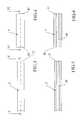
figure 1 shows a side view of flexible intramedullary reamer comprising a flexible shaft made of Nitinol, an interlayer made of pure Tantalum and a cutting head made of stainless steel welded together;figure 2 shows a sectional view of said flexible intramedullary reamer according to the line II-II infigure 1 ;figure 3 shows an end portion of the flexible shaft made of Nitinol before welding process;figure 4 shows an end portion of the interlayer made of pure Tantalum before welding process;figure 5 shows a sectional view according to the line V-V infigure 3 ;figure 6 shows a sectional view according to the line VI-VI infigure 4 ;figure 7 shows an end portion of the flexible shaft made of Nitinol welded together with interlayer of pure Tantalum;figure 8 shows an end portion of the cutting head made of stainless steel before welding process;figure 9 shows a sectional view according to the line IX-IX infigure 7 ;figure 10 shows a sectional view according to the line X-X infigure 8 .- With reference to the above-listed figures, a flexible
intramedullary reamer 1 for surgical operations to bones, comprises aflexible shaft 2 made of shape memory alloy and acutting head 3 welded together by means of aninterlayer rod 4 made of Tantalum, as shown infigure 1 . - Said flexible
intramedullary reamer 1 is suitable for being an instrument used for the treatment of the medullary space of bones. - The
cutting head 3 is at one end of the flexibleintramedullary reamer 1. - The other end of the
flexible shaft 2 comprises anadapter 25 for the connection of theflexible shaft 2 to a power drive mechanism thereby to cause rotation of theflexible shaft 2 and thecutting head 3. Saidflexible shaft 2 is rotatable. Theflexible shaft 2 is a monolithicflexible shaft 2 without dangerous interstices where microbes or bacteria could lurking. - In the treatment of the medullary space of bones flexible
intramedullary reamer 1 is used as a power-driven reamer for clearing, enlarging and reaming the medullary space of bones. - The joint between the
cutting head 3 and theflexible shaft 2 has to support high tensile strength and high torsional strength. - The
flexible shaft 2 is made of shape memory alloy (SMA hereinafter) such as Nickel Titanum alloy, because SMA has unique thermo-mechanical properties such as a shape memory effect (SME hereinafter) and a superelasticity (SE hereinafter) thanks to the martensitic transformation. Said transformation is an allotropic phase change wchich involves a martensitic (M hereinafter) and austenitic (A hereinafter) phase, the former stable a temperature below the latter. - Thus the SME phenomenon is related the recovery of the shape of a item made from SMA which can be deformed at stable Martensitic temperature maintaining the shape until it is heated up to the stable Austenitic temperature recovering the original shape. The transformation from M to A is promoted by temperature change.
- The SE phenomenon is due to the reverse transformation from A to M promoted by load application and in case of an item made from SMA with a stable Austenitic temperature near to Body or Room temperature it is possible to deform it applying a load causing deformation up to 8% and when load is released the item recovers the original shape without any permanent deformation. The SE is often exploited to manufacture object that have to be undergone to severe deformation without reaching rupture or presenting plastic deformation.
- Furthermore, during the loading and unloading process the mechanical behaviour of the SMAs is hysteretic so the mechanical hysteresis of SE elements is able to dissipate mechanical energy into heat allowing to be used as dissipative devices.
- The SE and intrinsic dissipative properties of SMAs provides an advantage for making flexible intramedullary reamer allowing to the shaft to experiment large deformation without breaking and to dissipate vibrations due to the drilling process reducing the possibility of blocking of the reamer reducing the number of steps to reach final hole diameter and increasing the precision of the same hole.
- This phenomenon provides an advantage for making flexible
intramedullary reamer 1. The most common shape memory material is an alloy of nickel and titanium called Nitinol, but it is provided to use also other SMAs. - In particular Nitinol has very good mechanical properties, long fatigue life, and high corrosion resistance in severe corrosion situations such as surgical situations. Nitinol also has resistance properties. In most cases, the transition temperature of the SMA is chosen such that room temperature is well below the transformation point of the material.
- Nitinol is preferably conforming to ATM F2063-05 standard.
- The
cutting head 3 is made of stainless steel to drill into marrow of long bone, such as femur or short bones or other bones in general. Stainless steel is safe for patients and reliable to thecutting head 3 avoiding its breaking and avoiding breaking into fragments dangerous for patients. - The stainless steel is preferably a 17-4PH (H900) stainless steel conforming to ASTM A564 standard.
- The
welding interlayer rod 4, between a portion of theflexible shaft 2 and a portion of thecutting head 3, is made of Tantalum. - Preferably Tantalum is a pure Tantalum conforming to ATM F560-08 (R05-200) standard, fully annealed, preferred maximum hardness of 88 HV to reach the better technical effect when used for interlayer according to the present invention.
- Tantalum is ideals for most severe corrosion situations such as surgical situations, in fact Tantalum is used in surgical application, but have too low tensile strength of only 230-250 Mpa for fully annealed bars. It discourages any skilled person to use Tantalum as an interlayer for welding.
- Many skilled persons use interlayers in Nickel which yields a tensile strength of 512 Mpa, but the use of interlayer made of Nickel is dangerous, because at the weld interface there is a large amount of intermetallic compounds formed causing crevices unsafe for patient. The formation of said compounds led to embrittlement of the joint strength causing break off unsafe for the patients.
- It is an unexpected surprise that the technical effect of
interlayer rod 4 made of Tantalum welded by means of rotary friction welding yields a tensile strength of 700 Mpa, advantageously higher than interlayer in Nickel and advantageously bio-compatible. Advantageously theinterlayer rod 4 made of Tantalum can resist to high tensile strength and to high torsional strength. - Further Tantalum has mechanical properties advantageously superior with respect to other bio-compatible materials such as gold or silver.
- As shown in
figure 2 the flexibleintramedullary reamer 1 comprise a through hole along its longitudinal axis. - As shown in
figures 3-10 theflexible shaft 2, theinterlayer 4 and the cuttinghead 3 are hollow tubes. The through hole of the flexibleintramedullary reamer 1 comprising a throughhole 20 of theflexible shaft 2, a throughhole 40 of theinterlayer 4 and a throughhole 30 of the cuttinghead 3 aligned together along said longitudinal axis and having same measures adapted for a guidewire suitable for passing through in surgical operation. - As shown in
figures 3 and 5 theflexible shaft 3 is a tube and comprises anend portion 21 with a flat surface. - As shown in
figures 4 and 6 theinterlayer 4 is a tube and comprises afirst end portion 42 with a flat surface and on the other side asecond end portion 41 with a flat surface. - As shown in
figures 8 and 10 the cuttinghead 3 is a tube and comprises anend portion 32 with a flat surface. - All the surfaces of the
end portions - As shown in
figures 8 and 10 , at theend portion 32 of the cuttinghead 3 the measure of diameter of theend portion 32 is reduced by creating aportion 35 comprising ashoulder 351 and achamfering 352 to provide an invitation to thesecond end 41 portion ofinterlayer 4. Theportion 35, theshoulder 351 and thechamfering 352 are advantageous for welding the cuttinghead 3 and a weldedgroup - With regards to the operation to make said flexible
intramedullary reamer 1, a method to joint together saidflexible shaft 2 made of shape memory alloy and said cuttinghead 3 of a flexibleintramedullary reamer 1 comprises a welding phase to weld saidflexible shaft 2 with said cuttinghead 3 by means of aninterlayer 4 made of Tantalum. - Said welding phase comprises at least two steps.
- Before a first welding step it is provided a first preparatory step to make flat the surface of the
first end 42 of saidinterlayer 4 and to make flat the surface of theend 21 of saidflexible shaft 2. - After the first preparatory step it is provided a first cleaning step to clean with a decontamination solution, such as acetone, the surface of the
first end 42 of saidinterlayer 4 and the surface of theend 21 of saidflexible shaft 2. - The first welding step is for welding said
first end portion 42 of saidinterlayer 4 by means of rotary friction welding with saidend portion 21 of saidflexible shaft 2. - Said first welding step forms the welded
group flexible shaft 2 welded together with saidinterlayer 4. - A second welding step is successive to said first welding step, but before the second welding step it is provided a second preparatory step to make flat the surface of the
second end portion 41 of saidinterlayer 4 and to make flat the surface of theend portion 32 of said cuttinghead 3. - The second preparatory step provides a further step to reduce the measure of diameter of the
end portion 32 by creating aportion 35 comprising ashoulder 351 and achamfering 352 to provide an invitation to thesecond end 41 portion ofinterlayer 4 which is advantageous for the second welding step. - After the second preparatory step it is provided a second cleaning step to clean with said decontamination solution the surface of the
second end 41 of saidinterlayer 4 and the surface of theend 32 of said cuttinghead 3. - Said second welding step for welding said
second end portion 41 of saidinterlayer 4 by means of rotary friction welding with saidend portion 32 of said cuttinghead 3. - Rotary friction welding techniques are know in the prior art.
- The means of rotary friction welding comprise a machine which comprises a rotary chuck suitable to rotate a portion with respect to an other portion. It generates heat through mechanical friction between said rotating portion and a stationary portion. No melt occurs, so the
flexible shaft 2 made of Nitinol does not deform itself. - In the first welding step the Nitinol portion of
flexible shaft 2 is mounted with a static clamp. Tantalum portion of theinterlayer 4 is mounted with said rotary chuck. - In the second welding step the Nitinol-Tantalum portion of the welded
group head 3 is mounted with said rotary chuck. - Revolution speed of said rotary chuck is set preferably to 3500 revolutions/minute to obtain a better result.
- After the first welding step, it is provided a first removing step, and after the second welding step, it is provided a second removing step.
- Rotary friction welding process produces welding burrs, such as upset and flash that needs to be removed.
- Said first and second removing steps suitable for removing by mechanical means said welding burrs from welding portions of the flexible
intramedullary reamer 1. - Alternatively the
flexible shaft 2, theinterlayer 4 and the cuttinghead 3 are solid bars without through holes. - A further alternative provides that said first welding step is successive to said second welding step.
- Advantageously rotary friction welding process synergistically combined with the interlayer of Tantalum successfully provides flexible
intramedullary reamer 1 with maximum stress level and highly reliable surgical instrument, all the materials of theinterlayer 4, the cuttinghead 3 and theflexible shaft 2 are bio-compatible. The flexible intramedullary reamer has an advantageusly high tensile strength, also in the joint welding portions. Welding portions and all the portions of the flexibleintramedullary reamer 1 are safe for patient, crevice free, easy to clean and maintain. - Advantageously the
interlayer 4 of Tantalum welded to Nitnol and to stainless steel by means of rotary friction welding, provides strong, resistance and resilient welds between stainless steel and Nitinol.
Claims (10)
- A flexible intramedullary reamer (1) comprising a flexible shaft (2) made of shape memory alloy and a cutting head (3) welded together,characterized in that said flexible shaft (2) is welded together with said cutting head (3) by means of an interlayer (4) made of Tantalum.
- A flexible intramedullary reamer (1) according to claim 1,characterized in that the flexible shaft (2) is made of Nickel Titanum alloy, the cutting head (3) is made of stainless steel and the interlayer (4) is made of pure Tantalum.
- A flexible intramedullary reamer (1) according to claims 1 or 2,characterized in that the flexible shaft (2), the interlayer (4) and the cutting head (3) are hollow tubes comprising a through hole (20) of the flexible shaft (2), a through hole (40) of the interlayer (4) and a through hole (30) of the cutting head (3) aligned together and having same measures adapted for a guidewire suitable for passing through.
- Method to joint together a flexible shaft (2) made of shape memory alloy and a cutting head (3) of a flexible intramedullary reamer (1),characterized in that comprises a welding phase to weld said flexible shaft (2) with said cutting head (3) by means of an interlayer (4) made of Tantalum.
- Method according to claim 4,characterized in that said welding phase comprises at least two steps,
a first welding step is for welding a first end portion (42) of said interlayer (4) by means of rotary friction welding with an end portion (21) of said flexible shaft (2), and
a second welding step is for welding a second end portion (41) of said interlayer (4) by means of rotary friction welding with an end portion (32) of said cutting head (3). - Method according to claim 5,characterized in that
said first welding step forms a first welded group (2, 4) consisting of said flexible shaft (2) welded together with said interlayer (4) and
said second welding step is successive to said first welding step. - Method according to the claims 5 or 6,characterized in that
before the first welding step it is provided a first preparatory step to make flat a surface of the first end portion (42) of said interlayer (4) and to make flat a surface of the end portion (21) of said flexible shaft (2), and
before the second welding step it is provided a second preparatory step to make flat a surface of the second end portion (41) of said interlayer (4) and to make flat a surface of the end portion (32) of said cutting head (3). - Method according to claim 7,characterized in that after the first preparatory step it is provided a first cleaning step to clean with a decontamination solution the surface of the first end portion (42) of said interlayer (4) and the surface of the end portion (21) of said flexible shaft (2), and
after the second preparatory step it is provided a second cleaning step to clean with said decontamination solution the surface of the second end portion (41) of said interlayer (4) and the surface of the end portion (32) of said cutting head (3). - Method according to anyone of the preceding claims 5-8,characterized in that
after the first welding step, it is provided a first removing step, and after the second welding step, it is provided a second removing step, said first and second removing steps are suitable for removing by mechanical means welding burrs from welding portions of the flexible intramedullary reamer (1). - Method according to anyone of the preceding claims 4-9,characterized in that the flexible shaft (2) is made of Nickel Titanum alloy, the cutting head (3) is made of stainless steel and the interlayer (4) is made of pure Tantalum.
Applications Claiming Priority (1)
| Application Number | Priority Date | Filing Date | Title |
|---|---|---|---|
| ITMI20141179 | 2014-06-27 |
Publications (2)
| Publication Number | Publication Date |
|---|---|
| EP2959851A1true EP2959851A1 (en) | 2015-12-30 |
| EP2959851B1 EP2959851B1 (en) | 2017-01-25 |
Family
ID=51454819
Family Applications (1)
| Application Number | Title | Priority Date | Filing Date |
|---|---|---|---|
| EP15173851.5ANot-in-forceEP2959851B1 (en) | 2014-06-27 | 2015-06-25 | Flexible intramedullary reamer |
Country Status (1)
| Country | Link |
|---|---|
| EP (1) | EP2959851B1 (en) |
Cited By (7)
| Publication number | Priority date | Publication date | Assignee | Title |
|---|---|---|---|---|
| US11963711B2 (en) | 2019-12-31 | 2024-04-23 | Applied Medical Resources Corporation | Electrosurgical system with tissue and maximum current identification |
| US12048431B2 (en) | 2020-10-29 | 2024-07-30 | Applied Medical Resources Corporation | Material combinations and processing methods for a surgical instrument |
| US12137907B2 (en) | 2013-03-15 | 2024-11-12 | Applied Medical Resources Corporation | Surgical stapler handle assembly having actuation mechanism with longitudinally rotatable shaft |
| US12144504B2 (en) | 2013-03-15 | 2024-11-19 | Applied Medical Resources Corporation | Surgical stapler with expandable jaw |
| US12161330B2 (en) | 2020-10-29 | 2024-12-10 | Applied Medical Resources Corporation | Actuation shaft retention mechanism for surgical stapler |
| US12161336B2 (en) | 2014-06-11 | 2024-12-10 | Applied Medical Resources Corporation | Surgical stapler with circumferential firing |
| US12324582B2 (en) | 2016-04-12 | 2025-06-10 | Applied Medical Resources Corporation | Surgical stapler having a powered handle |
Citations (7)
| Publication number | Priority date | Publication date | Assignee | Title |
|---|---|---|---|---|
| GB1360221A (en)* | 1970-07-20 | 1974-07-17 | Bendix Corp | Composite low cost heavy duty cutting tools |
| JPS58160008A (en)* | 1982-03-17 | 1983-09-22 | Sumitomo Electric Ind Ltd | Small diameter cemented carbide solid drill and manufature thereof |
| EP0253526A1 (en)* | 1986-06-27 | 1988-01-20 | DiPietropolo, Al | Flexible medullary reamer |
| US5499984A (en) | 1994-04-07 | 1996-03-19 | Snap-On Incorporated | Universal modular reamer system |
| US20080140078A1 (en)* | 2006-11-22 | 2008-06-12 | Sonoma Orthopedic Products, Inc. | Surgical tools for use in deploying bone repair devices |
| US8518044B2 (en) | 2007-02-09 | 2013-08-27 | Christopher G. Sidebotham | Disposable flexible reamer shaft for medical applications |
| DE102012211481A1 (en)* | 2012-07-03 | 2014-01-09 | Robert Bosch Gmbh | Method and device for producing a component |
- 2015
- 2015-06-25EPEP15173851.5Apatent/EP2959851B1/ennot_activeNot-in-force
Patent Citations (9)
| Publication number | Priority date | Publication date | Assignee | Title |
|---|---|---|---|---|
| GB1360221A (en)* | 1970-07-20 | 1974-07-17 | Bendix Corp | Composite low cost heavy duty cutting tools |
| JPS58160008A (en)* | 1982-03-17 | 1983-09-22 | Sumitomo Electric Ind Ltd | Small diameter cemented carbide solid drill and manufature thereof |
| EP0253526A1 (en)* | 1986-06-27 | 1988-01-20 | DiPietropolo, Al | Flexible medullary reamer |
| US4751922A (en) | 1986-06-27 | 1988-06-21 | Dipietropolo Al | Flexible medullary reamer |
| EP0253526B1 (en) | 1986-06-27 | 1993-03-10 | DiPietropolo, Al | Flexible medullary reamer |
| US5499984A (en) | 1994-04-07 | 1996-03-19 | Snap-On Incorporated | Universal modular reamer system |
| US20080140078A1 (en)* | 2006-11-22 | 2008-06-12 | Sonoma Orthopedic Products, Inc. | Surgical tools for use in deploying bone repair devices |
| US8518044B2 (en) | 2007-02-09 | 2013-08-27 | Christopher G. Sidebotham | Disposable flexible reamer shaft for medical applications |
| DE102012211481A1 (en)* | 2012-07-03 | 2014-01-09 | Robert Bosch Gmbh | Method and device for producing a component |
Cited By (9)
| Publication number | Priority date | Publication date | Assignee | Title |
|---|---|---|---|---|
| US12137907B2 (en) | 2013-03-15 | 2024-11-12 | Applied Medical Resources Corporation | Surgical stapler handle assembly having actuation mechanism with longitudinally rotatable shaft |
| US12144504B2 (en) | 2013-03-15 | 2024-11-19 | Applied Medical Resources Corporation | Surgical stapler with expandable jaw |
| US12161336B2 (en) | 2014-06-11 | 2024-12-10 | Applied Medical Resources Corporation | Surgical stapler with circumferential firing |
| US12324582B2 (en) | 2016-04-12 | 2025-06-10 | Applied Medical Resources Corporation | Surgical stapler having a powered handle |
| US11963711B2 (en) | 2019-12-31 | 2024-04-23 | Applied Medical Resources Corporation | Electrosurgical system with tissue and maximum current identification |
| US12402936B2 (en) | 2019-12-31 | 2025-09-02 | Applied Medical Resources Corporation | Electrosurgical system with tissue and maximum current identification |
| US12048431B2 (en) | 2020-10-29 | 2024-07-30 | Applied Medical Resources Corporation | Material combinations and processing methods for a surgical instrument |
| US12161330B2 (en) | 2020-10-29 | 2024-12-10 | Applied Medical Resources Corporation | Actuation shaft retention mechanism for surgical stapler |
| US12357304B2 (en) | 2020-10-29 | 2025-07-15 | Applied Medical Resources Corporation | Material combinations and processing methods for a surgical instrument |
Also Published As
| Publication number | Publication date |
|---|---|
| EP2959851B1 (en) | 2017-01-25 |
Similar Documents
| Publication | Publication Date | Title |
|---|---|---|
| EP2959851B1 (en) | Flexible intramedullary reamer | |
| US8518044B2 (en) | Disposable flexible reamer shaft for medical applications | |
| US10849668B2 (en) | Composite material bone implant | |
| JP5818819B2 (en) | Bars and how to make bars | |
| CN102469999B (en) | Surgical instrument used to cut out a cavity in the intramedullary canal | |
| EP3071139B1 (en) | Endodontic instruments formed from or coated with a porous material | |
| EP1883357B1 (en) | Laser-resistant surgical devices | |
| US10350715B2 (en) | Method of producing a medical cutting instrument | |
| JP6474906B2 (en) | Bone drilling reamer | |
| US9320611B2 (en) | Surgically implantable joint spacer | |
| Polishetty et al. | Machinability assessment of titanium alloy Ti-6Al-4V for biomedical applications | |
| US20190285205A1 (en) | Mechanical Joining Of Nitinol Tubes | |
| DE202008011612U1 (en) | Surgical tubular shaft instrument | |
| WO2018195282A1 (en) | Endodontic tool | |
| EP3803137B1 (en) | Mechanical joining of nitinol tubes | |
| KR20200076793A (en) | Medical burr | |
| Butsch et al. | Challenges in Manufacturing Miniaturized Active Implants with Shape Memory Alloy Wires | |
| WO2020131129A1 (en) | Mechanical joining of nitinol tubes |
Legal Events
| Date | Code | Title | Description |
|---|---|---|---|
| PUAI | Public reference made under article 153(3) epc to a published international application that has entered the european phase | Free format text:ORIGINAL CODE: 0009012 | |
| AK | Designated contracting states | Kind code of ref document:A1 Designated state(s):AL AT BE BG CH CY CZ DE DK EE ES FI FR GB GR HR HU IE IS IT LI LT LU LV MC MK MT NL NO PL PT RO RS SE SI SK SM TR | |
| AX | Request for extension of the european patent | Extension state:BA ME | |
| 17P | Request for examination filed | Effective date:20160629 | |
| GRAP | Despatch of communication of intention to grant a patent | Free format text:ORIGINAL CODE: EPIDOSNIGR1 | |
| RBV | Designated contracting states (corrected) | Designated state(s):AL AT BE BG CH CY CZ DE DK EE ES FI FR GB GR HR HU IE IS IT LI LT LU LV MC MK MT NL NO PL PT RO RS SE SI SK SM TR | |
| RIC1 | Information provided on ipc code assigned before grant | Ipc:A61B 17/16 20060101AFI20160721BHEP | |
| INTG | Intention to grant announced | Effective date:20160811 | |
| GRAS | Grant fee paid | Free format text:ORIGINAL CODE: EPIDOSNIGR3 | |
| GRAA | (expected) grant | Free format text:ORIGINAL CODE: 0009210 | |
| AK | Designated contracting states | Kind code of ref document:B1 Designated state(s):AL AT BE BG CH CY CZ DE DK EE ES FI FR GB GR HR HU IE IS IT LI LT LU LV MC MK MT NL NO PL PT RO RS SE SI SK SM TR | |
| REG | Reference to a national code | Ref country code:GB Ref legal event code:FG4D | |
| REG | Reference to a national code | Ref country code:CH Ref legal event code:EP | |
| REG | Reference to a national code | Ref country code:AT Ref legal event code:REF Ref document number:863645 Country of ref document:AT Kind code of ref document:T Effective date:20170215 | |
| REG | Reference to a national code | Ref country code:IE Ref legal event code:FG4D | |
| REG | Reference to a national code | Ref country code:DE Ref legal event code:R096 Ref document number:602015001346 Country of ref document:DE | |
| REG | Reference to a national code | Ref country code:FR Ref legal event code:PLFP Year of fee payment:3 | |
| REG | Reference to a national code | Ref country code:LT Ref legal event code:MG4D | |
| REG | Reference to a national code | Ref country code:NL Ref legal event code:MP Effective date:20170125 | |
| REG | Reference to a national code | Ref country code:AT Ref legal event code:MK05 Ref document number:863645 Country of ref document:AT Kind code of ref document:T Effective date:20170125 | |
| PG25 | Lapsed in a contracting state [announced via postgrant information from national office to epo] | Ref country code:NL Free format text:LAPSE BECAUSE OF FAILURE TO SUBMIT A TRANSLATION OF THE DESCRIPTION OR TO PAY THE FEE WITHIN THE PRESCRIBED TIME-LIMIT Effective date:20170125 | |
| PG25 | Lapsed in a contracting state [announced via postgrant information from national office to epo] | Ref country code:FI Free format text:LAPSE BECAUSE OF FAILURE TO SUBMIT A TRANSLATION OF THE DESCRIPTION OR TO PAY THE FEE WITHIN THE PRESCRIBED TIME-LIMIT Effective date:20170125 Ref country code:IS Free format text:LAPSE BECAUSE OF FAILURE TO SUBMIT A TRANSLATION OF THE DESCRIPTION OR TO PAY THE FEE WITHIN THE PRESCRIBED TIME-LIMIT Effective date:20170525 Ref country code:LT Free format text:LAPSE BECAUSE OF FAILURE TO SUBMIT A TRANSLATION OF THE DESCRIPTION OR TO PAY THE FEE WITHIN THE PRESCRIBED TIME-LIMIT Effective date:20170125 Ref country code:NO Free format text:LAPSE BECAUSE OF FAILURE TO SUBMIT A TRANSLATION OF THE DESCRIPTION OR TO PAY THE FEE WITHIN THE PRESCRIBED TIME-LIMIT Effective date:20170425 Ref country code:GR Free format text:LAPSE BECAUSE OF FAILURE TO SUBMIT A TRANSLATION OF THE DESCRIPTION OR TO PAY THE FEE WITHIN THE PRESCRIBED TIME-LIMIT Effective date:20170426 Ref country code:HR Free format text:LAPSE BECAUSE OF FAILURE TO SUBMIT A TRANSLATION OF THE DESCRIPTION OR TO PAY THE FEE WITHIN THE PRESCRIBED TIME-LIMIT Effective date:20170125 | |
| PGFP | Annual fee paid to national office [announced via postgrant information from national office to epo] | Ref country code:DE Payment date:20170424 Year of fee payment:3 Ref country code:FR Payment date:20170509 Year of fee payment:3 | |
| PG25 | Lapsed in a contracting state [announced via postgrant information from national office to epo] | Ref country code:BG Free format text:LAPSE BECAUSE OF FAILURE TO SUBMIT A TRANSLATION OF THE DESCRIPTION OR TO PAY THE FEE WITHIN THE PRESCRIBED TIME-LIMIT Effective date:20170425 Ref country code:ES Free format text:LAPSE BECAUSE OF FAILURE TO SUBMIT A TRANSLATION OF THE DESCRIPTION OR TO PAY THE FEE WITHIN THE PRESCRIBED TIME-LIMIT Effective date:20170125 Ref country code:PT Free format text:LAPSE BECAUSE OF FAILURE TO SUBMIT A TRANSLATION OF THE DESCRIPTION OR TO PAY THE FEE WITHIN THE PRESCRIBED TIME-LIMIT Effective date:20170525 Ref country code:PL Free format text:LAPSE BECAUSE OF FAILURE TO SUBMIT A TRANSLATION OF THE DESCRIPTION OR TO PAY THE FEE WITHIN THE PRESCRIBED TIME-LIMIT Effective date:20170125 Ref country code:RS Free format text:LAPSE BECAUSE OF FAILURE TO SUBMIT A TRANSLATION OF THE DESCRIPTION OR TO PAY THE FEE WITHIN THE PRESCRIBED TIME-LIMIT Effective date:20170125 Ref country code:AT Free format text:LAPSE BECAUSE OF FAILURE TO SUBMIT A TRANSLATION OF THE DESCRIPTION OR TO PAY THE FEE WITHIN THE PRESCRIBED TIME-LIMIT Effective date:20170125 Ref country code:SE Free format text:LAPSE BECAUSE OF FAILURE TO SUBMIT A TRANSLATION OF THE DESCRIPTION OR TO PAY THE FEE WITHIN THE PRESCRIBED TIME-LIMIT Effective date:20170125 Ref country code:LV Free format text:LAPSE BECAUSE OF FAILURE TO SUBMIT A TRANSLATION OF THE DESCRIPTION OR TO PAY THE FEE WITHIN THE PRESCRIBED TIME-LIMIT Effective date:20170125 | |
| REG | Reference to a national code | Ref country code:DE Ref legal event code:R097 Ref document number:602015001346 Country of ref document:DE | |
| PG25 | Lapsed in a contracting state [announced via postgrant information from national office to epo] | Ref country code:IT Free format text:LAPSE BECAUSE OF FAILURE TO SUBMIT A TRANSLATION OF THE DESCRIPTION OR TO PAY THE FEE WITHIN THE PRESCRIBED TIME-LIMIT Effective date:20170125 Ref country code:CZ Free format text:LAPSE BECAUSE OF FAILURE TO SUBMIT A TRANSLATION OF THE DESCRIPTION OR TO PAY THE FEE WITHIN THE PRESCRIBED TIME-LIMIT Effective date:20170125 Ref country code:RO Free format text:LAPSE BECAUSE OF FAILURE TO SUBMIT A TRANSLATION OF THE DESCRIPTION OR TO PAY THE FEE WITHIN THE PRESCRIBED TIME-LIMIT Effective date:20170125 Ref country code:SK Free format text:LAPSE BECAUSE OF FAILURE TO SUBMIT A TRANSLATION OF THE DESCRIPTION OR TO PAY THE FEE WITHIN THE PRESCRIBED TIME-LIMIT Effective date:20170125 Ref country code:EE Free format text:LAPSE BECAUSE OF FAILURE TO SUBMIT A TRANSLATION OF THE DESCRIPTION OR TO PAY THE FEE WITHIN THE PRESCRIBED TIME-LIMIT Effective date:20170125 | |
| PG25 | Lapsed in a contracting state [announced via postgrant information from national office to epo] | Ref country code:SM Free format text:LAPSE BECAUSE OF FAILURE TO SUBMIT A TRANSLATION OF THE DESCRIPTION OR TO PAY THE FEE WITHIN THE PRESCRIBED TIME-LIMIT Effective date:20170125 Ref country code:DK Free format text:LAPSE BECAUSE OF FAILURE TO SUBMIT A TRANSLATION OF THE DESCRIPTION OR TO PAY THE FEE WITHIN THE PRESCRIBED TIME-LIMIT Effective date:20170125 | |
| PLBE | No opposition filed within time limit | Free format text:ORIGINAL CODE: 0009261 | |
| STAA | Information on the status of an ep patent application or granted ep patent | Free format text:STATUS: NO OPPOSITION FILED WITHIN TIME LIMIT | |
| 26N | No opposition filed | Effective date:20171026 | |
| PG25 | Lapsed in a contracting state [announced via postgrant information from national office to epo] | Ref country code:MC Free format text:LAPSE BECAUSE OF FAILURE TO SUBMIT A TRANSLATION OF THE DESCRIPTION OR TO PAY THE FEE WITHIN THE PRESCRIBED TIME-LIMIT Effective date:20170125 | |
| PG25 | Lapsed in a contracting state [announced via postgrant information from national office to epo] | Ref country code:SI Free format text:LAPSE BECAUSE OF FAILURE TO SUBMIT A TRANSLATION OF THE DESCRIPTION OR TO PAY THE FEE WITHIN THE PRESCRIBED TIME-LIMIT Effective date:20170125 | |
| REG | Reference to a national code | Ref country code:IE Ref legal event code:MM4A | |
| PG25 | Lapsed in a contracting state [announced via postgrant information from national office to epo] | Ref country code:LU Free format text:LAPSE BECAUSE OF NON-PAYMENT OF DUE FEES Effective date:20170625 Ref country code:IE Free format text:LAPSE BECAUSE OF NON-PAYMENT OF DUE FEES Effective date:20170625 | |
| REG | Reference to a national code | Ref country code:BE Ref legal event code:MM Effective date:20170630 | |
| PG25 | Lapsed in a contracting state [announced via postgrant information from national office to epo] | Ref country code:BE Free format text:LAPSE BECAUSE OF NON-PAYMENT OF DUE FEES Effective date:20170630 | |
| PG25 | Lapsed in a contracting state [announced via postgrant information from national office to epo] | Ref country code:MT Free format text:LAPSE BECAUSE OF NON-PAYMENT OF DUE FEES Effective date:20170625 | |
| REG | Reference to a national code | Ref country code:DE Ref legal event code:R119 Ref document number:602015001346 Country of ref document:DE | |
| REG | Reference to a national code | Ref country code:CH Ref legal event code:PL | |
| PG25 | Lapsed in a contracting state [announced via postgrant information from national office to epo] | Ref country code:LI Free format text:LAPSE BECAUSE OF NON-PAYMENT OF DUE FEES Effective date:20180630 Ref country code:FR Free format text:LAPSE BECAUSE OF NON-PAYMENT OF DUE FEES Effective date:20180630 Ref country code:CH Free format text:LAPSE BECAUSE OF NON-PAYMENT OF DUE FEES Effective date:20180630 Ref country code:DE Free format text:LAPSE BECAUSE OF NON-PAYMENT OF DUE FEES Effective date:20190101 | |
| PG25 | Lapsed in a contracting state [announced via postgrant information from national office to epo] | Ref country code:HU Free format text:LAPSE BECAUSE OF FAILURE TO SUBMIT A TRANSLATION OF THE DESCRIPTION OR TO PAY THE FEE WITHIN THE PRESCRIBED TIME-LIMIT; INVALID AB INITIO Effective date:20150625 | |
| PG25 | Lapsed in a contracting state [announced via postgrant information from national office to epo] | Ref country code:CY Free format text:LAPSE BECAUSE OF FAILURE TO SUBMIT A TRANSLATION OF THE DESCRIPTION OR TO PAY THE FEE WITHIN THE PRESCRIBED TIME-LIMIT Effective date:20170125 | |
| PG25 | Lapsed in a contracting state [announced via postgrant information from national office to epo] | Ref country code:MK Free format text:LAPSE BECAUSE OF FAILURE TO SUBMIT A TRANSLATION OF THE DESCRIPTION OR TO PAY THE FEE WITHIN THE PRESCRIBED TIME-LIMIT Effective date:20170125 | |
| GBPC | Gb: european patent ceased through non-payment of renewal fee | Effective date:20190625 | |
| PG25 | Lapsed in a contracting state [announced via postgrant information from national office to epo] | Ref country code:TR Free format text:LAPSE BECAUSE OF FAILURE TO SUBMIT A TRANSLATION OF THE DESCRIPTION OR TO PAY THE FEE WITHIN THE PRESCRIBED TIME-LIMIT Effective date:20170125 | |
| PG25 | Lapsed in a contracting state [announced via postgrant information from national office to epo] | Ref country code:GB Free format text:LAPSE BECAUSE OF NON-PAYMENT OF DUE FEES Effective date:20190625 | |
| PG25 | Lapsed in a contracting state [announced via postgrant information from national office to epo] | Ref country code:AL Free format text:LAPSE BECAUSE OF FAILURE TO SUBMIT A TRANSLATION OF THE DESCRIPTION OR TO PAY THE FEE WITHIN THE PRESCRIBED TIME-LIMIT Effective date:20170125 |