EP2958665B1 - Assembly including serially connected spiral wound modules with permeate flow controller - Google Patents
Assembly including serially connected spiral wound modules with permeate flow controllerDownload PDFInfo
- Publication number
- EP2958665B1 EP2958665B1EP14724946.0AEP14724946AEP2958665B1EP 2958665 B1EP2958665 B1EP 2958665B1EP 14724946 AEP14724946 AEP 14724946AEP 2958665 B1EP2958665 B1EP 2958665B1
- Authority
- EP
- European Patent Office
- Prior art keywords
- permeate
- flow controller
- spiral wound
- assembly
- pressure vessel
- Prior art date
- Legal status (The legal status is an assumption and is not a legal conclusion. Google has not performed a legal analysis and makes no representation as to the accuracy of the status listed.)
- Active
Links
Images

Classifications
- B—PERFORMING OPERATIONS; TRANSPORTING
- B01—PHYSICAL OR CHEMICAL PROCESSES OR APPARATUS IN GENERAL
- B01D—SEPARATION
- B01D63/00—Apparatus in general for separation processes using semi-permeable membranes
- B01D63/10—Spiral-wound membrane modules
- B01D63/12—Spiral-wound membrane modules comprising multiple spiral-wound assemblies
- B—PERFORMING OPERATIONS; TRANSPORTING
- B01—PHYSICAL OR CHEMICAL PROCESSES OR APPARATUS IN GENERAL
- B01D—SEPARATION
- B01D63/00—Apparatus in general for separation processes using semi-permeable membranes
- B01D63/10—Spiral-wound membrane modules
- B01D63/107—Specific properties of the central tube or the permeate channel
- B—PERFORMING OPERATIONS; TRANSPORTING
- B01—PHYSICAL OR CHEMICAL PROCESSES OR APPARATUS IN GENERAL
- B01D—SEPARATION
- B01D2313/00—Details relating to membrane modules or apparatus
- B01D2313/19—Specific flow restrictors
- B—PERFORMING OPERATIONS; TRANSPORTING
- B01—PHYSICAL OR CHEMICAL PROCESSES OR APPARATUS IN GENERAL
- B01D—SEPARATION
- B01D2319/00—Membrane assemblies within one housing
- B01D2319/02—Elements in series
- B01D2319/022—Reject series
Definitions
- the inventionis directed toward assemblies including serially connected spiral modules.
- Spiral wound filtration assembliesare used in a wide variety of fluid separations.
- a plurality of spiral wound membrane modules(“elements") are serially arranged and interconnected within a pressure vessel.
- feed fluidis introduced into the vessel, successively passes through the individual modules and exits the vessel in at least two streams: concentrate and permeate.
- Feed fluidflows through the vessel and becomes increasingly concentrated as permeate passes through the individual modules.
- feed pressure within the vesselcontinually decreases due to resistance of the feed spacer and permeate back pressure increases.
- US 4046685draws permeate from both ends of the assembly which reduces permeate back pressure
- US 5503735utilizes a downstream flow restrictor to restrict concentrate flow
- US 2007/0272628utilizes a combination of elements having different standard specific flux values to better manage differences in operating conditions across the vessel
- WO 2012/086478utilizes a resistance pipe fixed within the permeate tube of an upstream element to reduce permeate flow
- US 7410581describes the use of flow restrictors that can be moved to alternative positioned along the permeate tubes of interconnected modules.
- EP 2008705 A1discloses a spiral wound assembly that comprises a permeate channel that has at least one flow restriction for increasing the pressure in at least part of the permeate channel.
- the present inventionis directed toward a spiral wound assembly comprising:
- the present inventionincludes spiral wound modules ("elements") suitable for use in reverse osmosis (RO) and nanofiltration (NF).
- modulesinclude one or more RO or NF membrane envelops and feed spacer sheets wound around a permeate collection tube.
- RO membranes used to form envelopsare relatively impermeable to virtually all dissolved salts and typically reject more than about 95% of salts having monovalent ions such as sodium chloride.
- RO membranesalso typically reject more than about 95% of inorganic molecules as well as organic molecules with molecular weights greater than approximately 100 Daltons.
- NF membranesare more permeable than RO membranes and typically reject less than about 95% of salts having monovalent ions while rejecting more than about 50% (and often more than 90%) of salts having divalent ions - depending upon the species of divalent ion. NF membranes also typically reject particles in the nanometer range as well as organic molecules having molecular weights greater than approximately 200 to 500 Daltons.
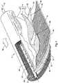
- a representative spiral wound filtration moduleis generally shown in Figure 1 .
- the module (2)is formed by concentrically winding one or more membrane envelopes (4) and feed spacer sheet(s) ("feed spacers ") (6) about a permeate collection tube (8).
- Each membrane envelope (4)preferably comprises two substantially rectangular sections of membrane sheet (10, 10').
- Each section of membrane sheet (10, 10')has a membrane or front side (34) and support or back side (36).
- the membrane envelope (4)is formed by overlaying membrane sheets (10, 10') and aligning their edges.
- the sections (10, 10') of membrane sheetsurround a permeate channel spacer sheet (“permeate spacer") (12). This sandwich-type structure is secured together, e.g.
- the module (2)preferably comprises a plurality of membrane envelopes (4) separated by a plurality of feed spacers sheets (6).
- membrane envelopes (4)are formed by joining the back side (36) surfaces of adjacently positioned membrane leaf packets.
- a membrane leaf packetcomprises a substantially rectangular membrane sheet (10) folded upon itself to define two membrane “leaves” wherein the front sides (34) of each leaf are facing each other and the fold is axially aligned with the proximal edge (22) of the membrane envelope (4), i.e. parallel with the permeate collection tube (8).
- a feed spacer sheet (6)is shown located between facing front sides (34) of the folded membrane sheet (10). The feed spacer sheet (6) facilitates flow of feed fluid in an axial direction (i.e. parallel with the permeate collection tube (8)) through the module (2). While not shown, additional intermediate layers may also be included in the assembly. Representative examples of membrane leaf packets and their fabrication are further described in US 7875177 .
- permeate spacer sheets (12)may be attached about the circumference of the permeate collection tube (8) with membrane leaf packets interleaved there between.
- the back sides (36) of adjacently positioned membrane leaves (10, 10')are sealed about portions of their periphery (16, 18, 20) to enclose the permeate spacer sheet (12) to form a membrane envelope (4).
- Suitable techniques for attaching the permeate spacer sheet to the permeate collection tubeare described in US 5538642 .
- the membrane envelope(s) (4) and feed spacer(s) (6)are wound or "rolled" concentrically about the permeate collection tube (8) to form two opposing scroll faces (30, 32) at opposing ends and the resulting spiral bundle is held in place, such as by tape or other means.
- the scroll faces of the (30, 32)may then be trimmed and a sealant may optionally be applied at the junction between the scroll face (30, 32) and permeate collection tube (8), as described in US 7951295 .
- Long glass fibersmay be wound about the partially constructed module and resin (e.g. liquid epoxy) applied and hardened.
- resine.g. liquid epoxy
- tapemay be applied upon the circumference of the wound module as described in US 8142588 .
- modulesmay be fitted with an anti-telescoping device or end cap (not shown) designed to prevent membrane envelopes from shifting under the pressure differential between the inlet and outlet scroll ends of the module.
- an anti-telescoping device or end cap(not shown) designed to prevent membrane envelopes from shifting under the pressure differential between the inlet and outlet scroll ends of the module.
- Representative examplesare described in: US 5851356 , US 6224767 , US 7063789 and US 7198719 .
- preferred embodiments of the inventioninclude end caps which include a locking structure for preventing relative axial movement between engaged end caps. Such a locking structure between end caps may be engaged by aligning adjacent end caps so that one or more projections or catches extending radially inward from the inside of the outer hub of one end cap enter corresponding receptacles arranged about the outer hub of the facing end cap.
- end capsare then engaged by rotating one end cap relative to the other until the projections or "catches” contact or “hook” with a corresponding structure of the receptacle.
- This type of locking end capis available from The Dow Chemical Company under the iLEC TM mark and is further described in US 6632356 and US 2011/0042294 .
- interconnecting tubesas shown in Figure 2
- various types of sealsmay be positioned between the outer periphery of the elements and the inner periphery of the vessel.
- seal assembliesare equipped with a bypass that permits limited feed fluid to flow around the elements, e.g. see US 5128037 , US 7208088 and WO 2013/015971 .
- Suitable sealants for sealing membrane envelopesinclude urethanes, epoxies, silicones, acrylates, hot melt adhesives and UV curable adhesives. While less common, other sealing means may also be used such as application of heat, pressure, ultrasonic welding and tape.
- Permeate collection tubesare typically made from plastic materials such as acrylonitrile-butadiene-styrene, polyvinyl chloride, polysulfone, poly (phenylene oxide), polystyrene, polypropylene, polyethylene or the like. Tricot polyester materials are commonly used as permeate spacers. Additional permeate spacers are described in US 2010/0006504 .
- Representative feed spacersinclude polyethylene, polyester, and polypropylene mesh materials such as those commercially available under the trade name VEXARTM from Conwed Plastics. Preferred feed spacers are described in US 6881336 .
- the membrane sheetis not particularly limited and a wide variety of materials may be used, e.g. cellulose acetate materials, polysulfone, polyether sulfone, polyamides, polyvinylidene fluoride, etc.
- a preferred membrane sheetincludes FilmTec Corporation's FT-30TM type membranes, i.e. a flat sheet composite membrane comprising a backing layer (back side) of a nonwoven backing web (e.g. a non-woven fabric such as polyester fiber fabric available from Awa Paper Company), a middle layer comprising a porous support having a typical thickness of about 25-125 ⁇ m and top discriminating layer (front side) comprising a thin film polyamide layer having a thickness typically less than about 1 micron, e.g.
- the backing layeris not particularly limited but preferably comprises a non-woven fabric or fibrous web mat including fibers which may be orientated. Alternatively, a woven fabric such as sail cloth may be used. Representative examples are described in US 4,214,994 ; US 4,795,559 ; US 5,435,957 ; US 5,919,026 ; US 6,156,680 ; US 2008/0295951 and US 7,048,855 .
- the porous supportis typically a polymeric material having pore sizes which are of sufficient size to permit essentially unrestricted passage of permeate but not large enough so as to interfere with the bridging over of a thin film polyamide layer formed thereon.
- the pore size of the supportpreferably ranges from about 0.001 to 0.5 ⁇ m.
- porous supportsinclude those made of: polysulfone, polyether sulfone, polyimide, polyamide, polyetherimide, polyacrylonitrile, poly(methyl methacrylate), polyethylene, polypropylene, and various halogenated polymers such as polyvinylidene fluoride.
- the discriminating layeris preferably formed by an interfacial polycondensation reaction between a polyfunctional amine monomer and a polyfunctional acyl halide monomer upon the surface of the microporous polymer layer as described in US 4277344 and US 6878278 .
- Feed fluidenters the module (2) from an inlet scroll face (30) and flows across the front side(s) (34) of the membrane sheet(s) and exits the module (2) at the opposing outlet scroll face (32).
- Permeate fluidflows along the permeate spacer sheet (12) in a direction approximately perpendicular to the feed flow as indicated by arrow (28). Actual fluid flow paths vary with details of construction and operating conditions.
- modulesare available in a variety of sizes, one common industrial RO module is available with a standard 8 inch (20.3 cm) diameter and 40 inch (101.6 cm) length. For a typical 8 inch diameter module, 26 to 30 individual membrane envelopes are wound around the permeate collection tube (i.e. for permeate collection tubes having an outer diameter of from about 1.5 to 1.9 inches (3.8 cm - 4.8)). Less conventional modules may also be used, including those described in US 2011/023206 and WO 2012/058038 .
- the pressure vessels used in the present inventionare not particularly limited but preferably include a solid structure capable of withstanding pressures associated with operating conditions.
- the vessel structurepreferably includes a chamber having an inner periphery corresponding to that of the outer periphery of the spiral wound modules to be housed therein.
- the length of the chamberpreferably corresponds to the combined length of the elements to be sequentially (axially) loaded, e.g. 2 to 8 elements, see US 2007/0272628 .
- the pressure vesselmay also include one or more end plates that seal the chamber once loaded with modules.
- the vesselfurther includes at least one fluid inlet (feed) and two fluid outlets (concentrate and permeate), preferably located at opposite ends of the chamber.
- the orientation of the pressure vesselis not particularly limited, e.g.
- a representative embodiment of the subject assemblyis generally shown at 38 in Figure 2 , including a pressure vessel (40) with a feed inlet (42), concentrate outlet (44) and permeate outlet (46).
- the feed inlet (42)is adapted for connection with a pressurized source of feed liquid.
- the concentrate outlet (42)is adapted for connection to a pathway for re-use or disposal.
- the permeate outlet (46)is adapted for connection to a pathway for storage, use or further treatment.
- Six spiral wound modules (2)are serially arranged within the vessel (40) with a first element (2') of the series positioned adjacent to a first end (48) of the pressure vessel (40) and a last element (2") of the series positioned adjacent to an opposing second end (50) of the pressure vessel (40).
- the permeate tubes (8) of the spiral wound elementsare serially connected to form a permeate pathway which is connected to the permeate outlet (46).
- the means for connecting the tubes (8) of the modulesis not particularly limited.
- interconnecting tubes (52) or end caps (not shown)which typically include pressure fit seals or O-rings are common in the art and are suitable for use in the present invention. While shown including six modules, other quantities may be used, e.g. 2 to 12.
- At least three modulesare included within the assembly (38). While shown including only one feed (42), concentrate (44) and permeate (46) outlet, multiple outlets and inlets may be used.
- the inlet and outletsare positioned at locations adjacent the ends (48, 50) of the vessel (40).
- the assembly (38)includes one feed inlet (42) and one concentration outlet (44) located at the ends (48, 50) of the vessel (40). Further preferred embodiments include removing permeate from only one end of the vessel (40).
- the "ends" of the vesselincludes those portions extending beyond the distal or axial ends of the modules positioned within the vessel.
- the inlets and outletsmay be position on the radial sides of a cylindrical vessel or at an axial position as illustrated in Figure 2 .
- a flow controller (54)is positioned along the permeate pathway and provides resistance that varies as a function of permeate flow, i.e. increasing resistance as permeate flow increases.
- Pressure drop across the flow controller (54)always increases monotonically with flow, but the resistance value is not a constant and can change with flow.
- the flow controller (54)increases resistance as flow (or pressure drop) across the flow controller (54) increases. In this way, flow across the flow controller can be maintained relatively constant in operation over a desired pressure range. Alternatively stated, the pressure drop can increase by a factor of two, four, oven even ten, with only a 10% change in flow.
- a 5 GPM flow controllere.g. model# 2305-1141-3/4 available from O'Keefe Controls Co.
- the flow controllerincludes a compliant member that can deform to cause greater resistance to flow at higher permeate flow rates or greater pressure drops across the flow controller.
- the flow controllerincludes an orifice that becomes partially obstructed or changes shape, i.e. narrowing as permeate flow increases and opening as permeate flow decreases.
- the degree of pressure drop created by the flow controllermay be optimized based upon the characteristics of the assembly, e.g. number of modules, quality of feed liquid, feed operating pressure, etc.
- the flow controllercreates a drop in permeate pressure of at least 0.6895 bar (10 PSI) when the permeate flow rate upstream from the flow controller is 25,510 liters/m2/hour (15 gfd) x Area, wherein the "Area” is the total membrane area of membrane located upstream from the flow controller (54).
- upstreamis defined in terms of the direction of permeate flow through the flow controller (54).
- a single flow controller (54)is shown located between the third and fifth module of the series.
- the flow controlleris located between the first (2') and last (2") module in the series. In embodiments including six modules like that shown, the flow controller is preferably located between the first (2') and fifth module.
- the flow controller (54)is located upstream of the third element. While shown at a single fixed location, the flow controller (54) may be selectively moved along the permeate pathway by conventional means, see for example US 7410581 . While not shown, the assembly (38) may include a plurality of flow controllers spaced along the permeate pathway, each providing a successive pressure drop.
Landscapes
- Chemical & Material Sciences (AREA)
- Chemical Kinetics & Catalysis (AREA)
- Separation Using Semi-Permeable Membranes (AREA)
Description
- The invention is directed toward assemblies including serially connected spiral modules.
- Spiral wound filtration assemblies are used in a wide variety of fluid separations. In a conventional embodiment, a plurality of spiral wound membrane modules ("elements") are serially arranged and interconnected within a pressure vessel. During operation pressurized feed fluid is introduced into the vessel, successively passes through the individual modules and exits the vessel in at least two streams: concentrate and permeate. Feed fluid flows through the vessel and becomes increasingly concentrated as permeate passes through the individual modules. Simultaneously, feed pressure within the vessel continually decreases due to resistance of the feed spacer and permeate back pressure increases. These effects result in permeate flux imbalances between individual elements that can lead to premature membrane fouling. Permeate flux imbalance reduces the volume of water than can be produced by the assembly without exceeding maximum flux guidelines for individual modules.
- A variety of techniques have been used to mitigate these effects. For example:
US 4046685 draws permeate from both ends of the assembly which reduces permeate back pressure;US 5503735 utilizes a downstream flow restrictor to restrict concentrate flow;US 2007/0272628 utilizes a combination of elements having different standard specific flux values to better manage differences in operating conditions across the vessel;WO 2012/086478 utilizes a resistance pipe fixed within the permeate tube of an upstream element to reduce permeate flow; andUS 7410581 describes the use of flow restrictors that can be moved to alternative positioned along the permeate tubes of interconnected modules.EP 2008705 A1 discloses a spiral wound assembly that comprises a permeate channel that has at least one flow restriction for increasing the pressure in at least part of the permeate channel. - The present invention is directed toward a spiral wound assembly comprising:
- i) a pressure vessel comprising a feed inlet, concentrate outlet and permeate outlet, and
- ii) a plurality of spiral wound modules, each comprising at least one membrane envelop wound around a permeate tube;
- The figures are not to scale and include idealized views to facilitate description. Where possible, like numerals have been used throughout the figures and written description to designate the same or similar features.
Figure 1 is a perspective, partially cut-away view of a spiral wound module.Figure 2 is a cross-sectional elevation view of an embodiment of the assembly.- The present invention includes spiral wound modules ("elements") suitable for use in reverse osmosis (RO) and nanofiltration (NF). Such modules include one or more RO or NF membrane envelops and feed spacer sheets wound around a permeate collection tube. RO membranes used to form envelops are relatively impermeable to virtually all dissolved salts and typically reject more than about 95% of salts having monovalent ions such as sodium chloride. RO membranes also typically reject more than about 95% of inorganic molecules as well as organic molecules with molecular weights greater than approximately 100 Daltons. NF membranes are more permeable than RO membranes and typically reject less than about 95% of salts having monovalent ions while rejecting more than about 50% (and often more than 90%) of salts having divalent ions - depending upon the species of divalent ion. NF membranes also typically reject particles in the nanometer range as well as organic molecules having molecular weights greater than approximately 200 to 500 Daltons.
- A representative spiral wound filtration module is generally shown in
Figure 1 . The module (2) is formed by concentrically winding one or more membrane envelopes (4) and feed spacer sheet(s) ("feed spacers ") (6) about a permeate collection tube (8). Each membrane envelope (4) preferably comprises two substantially rectangular sections of membrane sheet (10, 10'). Each section of membrane sheet (10, 10') has a membrane or front side (34) and support or back side (36). The membrane envelope (4) is formed by overlaying membrane sheets (10, 10') and aligning their edges. In a preferred embodiment, the sections (10, 10') of membrane sheet surround a permeate channel spacer sheet ("permeate spacer") (12). This sandwich-type structure is secured together, e.g. by sealant (14), along three edges (16, 18, 20) to form an envelope (4) while a fourth edge, i.e. "proximal edge" (22) abuts the permeate collection tube (8) so that the inside portion of the envelope (4) (and optional permeate spacer (12)) is in fluid communication with a plurality of openings (24) extending along the length of the permeate collection tube (8). The module (2) preferably comprises a plurality of membrane envelopes (4) separated by a plurality of feed spacers sheets (6). In the illustrated embodiment, membrane envelopes (4) are formed by joining the back side (36) surfaces of adjacently positioned membrane leaf packets. A membrane leaf packet comprises a substantially rectangular membrane sheet (10) folded upon itself to define two membrane "leaves" wherein the front sides (34) of each leaf are facing each other and the fold is axially aligned with the proximal edge (22) of the membrane envelope (4), i.e. parallel with the permeate collection tube (8). A feed spacer sheet (6) is shown located between facing front sides (34) of the folded membrane sheet (10). The feed spacer sheet (6) facilitates flow of feed fluid in an axial direction (i.e. parallel with the permeate collection tube (8)) through the module (2). While not shown, additional intermediate layers may also be included in the assembly. Representative examples of membrane leaf packets and their fabrication are further described inUS 7875177 . - During module fabrication, permeate spacer sheets (12) may be attached about the circumference of the permeate collection tube (8) with membrane leaf packets interleaved there between. The back sides (36) of adjacently positioned membrane leaves (10, 10') are sealed about portions of their periphery (16, 18, 20) to enclose the permeate spacer sheet (12) to form a membrane envelope (4). Suitable techniques for attaching the permeate spacer sheet to the permeate collection tube are described in
US 5538642 . The membrane envelope(s) (4) and feed spacer(s) (6) are wound or "rolled" concentrically about the permeate collection tube (8) to form two opposing scroll faces (30, 32) at opposing ends and the resulting spiral bundle is held in place, such as by tape or other means. The scroll faces of the (30, 32) may then be trimmed and a sealant may optionally be applied at the junction between the scroll face (30, 32) and permeate collection tube (8), as described inUS 7951295 . Long glass fibers may be wound about the partially constructed module and resin (e.g. liquid epoxy) applied and hardened. In an alternative embodiment, tape may be applied upon the circumference of the wound module as described inUS 8142588 . The ends of modules may be fitted with an anti-telescoping device or end cap (not shown) designed to prevent membrane envelopes from shifting under the pressure differential between the inlet and outlet scroll ends of the module. Representative examples are described in:US 5851356 ,US 6224767 ,US 7063789 andUS 7198719 . While not a required aspect of the invention, preferred embodiments of the invention include end caps which include a locking structure for preventing relative axial movement between engaged end caps. Such a locking structure between end caps may be engaged by aligning adjacent end caps so that one or more projections or catches extending radially inward from the inside of the outer hub of one end cap enter corresponding receptacles arranged about the outer hub of the facing end cap. The end caps are then engaged by rotating one end cap relative to the other until the projections or "catches" contact or "hook" with a corresponding structure of the receptacle. This type of locking end cap is available from The Dow Chemical Company under theiLEC™ mark and is further described inUS 6632356 andUS 2011/0042294 . If such end caps are not used, interconnecting tubes (as shown inFigure 2 ) may be used to prevent mixing of permeate with feed. In order to restrict feed fluid from bypassing the elements within the vessel, various types of seals (e.g. Chevron-type, O-rings, U-cup type, etc.) may be positioned between the outer periphery of the elements and the inner periphery of the vessel. Representative examples are described in:US 2011/084455 ,US 8388842 ,US 8110016 ,US 6299772 ,US 6066254 ,US 5851267 andWO 2010/090251 . In some embodiments, seal assemblies are equipped with a bypass that permits limited feed fluid to flow around the elements, e.g. seeUS 5128037 ,US 7208088 andWO 2013/015971 . - Materials for constructing various components of spiral wound modules are well known in the art. Suitable sealants for sealing membrane envelopes include urethanes, epoxies, silicones, acrylates, hot melt adhesives and UV curable adhesives. While less common, other sealing means may also be used such as application of heat, pressure, ultrasonic welding and tape. Permeate collection tubes are typically made from plastic materials such as acrylonitrile-butadiene-styrene, polyvinyl chloride, polysulfone, poly (phenylene oxide), polystyrene, polypropylene, polyethylene or the like. Tricot polyester materials are commonly used as permeate spacers. Additional permeate spacers are described in
US 2010/0006504 . Representative feed spacers include polyethylene, polyester, and polypropylene mesh materials such as those commercially available under the trade name VEXAR™ from Conwed Plastics. Preferred feed spacers are described inUS 6881336 . - The membrane sheet is not particularly limited and a wide variety of materials may be used, e.g. cellulose acetate materials, polysulfone, polyether sulfone, polyamides, polyvinylidene fluoride, etc. A preferred membrane sheet includes FilmTec Corporation's FT-30™ type membranes, i.e. a flat sheet composite membrane comprising a backing layer (back side) of a nonwoven backing web (e.g. a non-woven fabric such as polyester fiber fabric available from Awa Paper Company), a middle layer comprising a porous support having a typical thickness of about 25-125 µm and top discriminating layer (front side) comprising a thin film polyamide layer having a thickness typically less than about 1 micron, e.g. from 0.01 micron to 1 micron but more commonly from about 0.01 to 0.1 µm. The backing layer is not particularly limited but preferably comprises a non-woven fabric or fibrous web mat including fibers which may be orientated. Alternatively, a woven fabric such as sail cloth may be used. Representative examples are described in
US 4,214,994 ;US 4,795,559 ;US 5,435,957 ;US 5,919,026 ;US 6,156,680 ;US 2008/0295951 andUS 7,048,855 . The porous support is typically a polymeric material having pore sizes which are of sufficient size to permit essentially unrestricted passage of permeate but not large enough so as to interfere with the bridging over of a thin film polyamide layer formed thereon. For example, the pore size of the support preferably ranges from about 0.001 to 0.5 µm. Examples of porous supports include those made of: polysulfone, polyether sulfone, polyimide, polyamide, polyetherimide, polyacrylonitrile, poly(methyl methacrylate), polyethylene, polypropylene, and various halogenated polymers such as polyvinylidene fluoride. The discriminating layer is preferably formed by an interfacial polycondensation reaction between a polyfunctional amine monomer and a polyfunctional acyl halide monomer upon the surface of the microporous polymer layer as described inUS 4277344 andUS 6878278 . - Arrows shown in
Figure 1 represent the approximate flow directions (26, 28) of feed and permeate fluid (also referred to as "product" or "filtrate") during operation. Feed fluid enters the module (2) from an inlet scroll face (30) and flows across the front side(s) (34) of the membrane sheet(s) and exits the module (2) at the opposing outlet scroll face (32). Permeate fluid flows along the permeate spacer sheet (12) in a direction approximately perpendicular to the feed flow as indicated by arrow (28). Actual fluid flow paths vary with details of construction and operating conditions. - While modules are available in a variety of sizes, one common industrial RO module is available with a standard 8 inch (20.3 cm) diameter and 40 inch (101.6 cm) length. For a typical 8 inch diameter module, 26 to 30 individual membrane envelopes are wound around the permeate collection tube (i.e. for permeate collection tubes having an outer diameter of from about 1.5 to 1.9 inches (3.8 cm - 4.8)). Less conventional modules may also be used, including those described in
US 2011/023206 andWO 2012/058038 . - The pressure vessels used in the present invention are not particularly limited but preferably include a solid structure capable of withstanding pressures associated with operating conditions. The vessel structure preferably includes a chamber having an inner periphery corresponding to that of the outer periphery of the spiral wound modules to be housed therein. The length of the chamber preferably corresponds to the combined length of the elements to be sequentially (axially) loaded, e.g. 2 to 8 elements, see
US 2007/0272628 . The pressure vessel may also include one or more end plates that seal the chamber once loaded with modules. The vessel further includes at least one fluid inlet (feed) and two fluid outlets (concentrate and permeate), preferably located at opposite ends of the chamber. The orientation of the pressure vessel is not particularly limited, e.g. both horizontal and vertical orientations may be used. Examples of applicable pressure vessels, module arrangements and loading are described in:US 6074595 ,US 6165303 ,US 6299772 andUS 2008/0308504 . Manufacturers of pressure vessels include Pentair of Minneapolis MN, Bekaert of Vista CA and Bel Composite of Beer Sheva, Israel. - A representative embodiment of the subject assembly is generally shown at 38 in
Figure 2 , including a pressure vessel (40) with a feed inlet (42), concentrate outlet (44) and permeate outlet (46). The feed inlet (42) is adapted for connection with a pressurized source of feed liquid. The concentrate outlet (42) is adapted for connection to a pathway for re-use or disposal. The permeate outlet (46) is adapted for connection to a pathway for storage, use or further treatment. Six spiral wound modules (2) are serially arranged within the vessel (40) with a first element (2') of the series positioned adjacent to a first end (48) of the pressure vessel (40) and a last element (2") of the series positioned adjacent to an opposing second end (50) of the pressure vessel (40). The permeate tubes (8) of the spiral wound elements are serially connected to form a permeate pathway which is connected to the permeate outlet (46). The means for connecting the tubes (8) of the modules is not particularly limited. For example, interconnecting tubes (52) or end caps (not shown) which typically include pressure fit seals or O-rings are common in the art and are suitable for use in the present invention. While shown including six modules, other quantities may be used, e.g. 2 to 12. - In a preferred embodiment, at least three modules are included within the assembly (38). While shown including only one feed (42), concentrate (44) and permeate (46) outlet, multiple outlets and inlets may be used. In a preferred embodiment, the inlet and outlets are positioned at locations adjacent the ends (48, 50) of the vessel (40). In another embodiment, the assembly (38) includes one feed inlet (42) and one concentration outlet (44) located at the ends (48, 50) of the vessel (40). Further preferred embodiments include removing permeate from only one end of the vessel (40). For purposes of clarity, the "ends" of the vessel includes those portions extending beyond the distal or axial ends of the modules positioned within the vessel. For example, the inlets and outlets may be position on the radial sides of a cylindrical vessel or at an axial position as illustrated in
Figure 2 . - A flow controller (54) is positioned along the permeate pathway and provides resistance that varies as a function of permeate flow, i.e. increasing resistance as permeate flow increases. "Resistance" (R) is defined as the ratio of pressure drop (Δp) to flow (F), i.e. R=Δp/F. Pressure drop across the flow controller (54) always increases monotonically with flow, but the resistance value is not a constant and can change with flow. The flow controller (54) increases resistance as flow (or pressure drop) across the flow controller (54) increases. In this way, flow across the flow controller can be maintained relatively constant in operation over a desired pressure range. Alternatively stated, the pressure drop can increase by a factor of two, four, oven even ten, with only a 10% change in flow. For example, a 5 GPM flow controller (e.g. model# 2305-1141-3/4 available from O'Keefe Controls Co.) maintains flow within ± %10 of the flow rating as pressure drop ranges between 1 and 10 bar. By retarding flow for modules upstream of the flow controller (54), flux imbalances between different modules within the vessel (40) is reduced. The flow controller includes a compliant member that can deform to cause greater resistance to flow at higher permeate flow rates or greater pressure drops across the flow controller. The flow controller includes an orifice that becomes partially obstructed or changes shape, i.e. narrowing as permeate flow increases and opening as permeate flow decreases.
- The degree of pressure drop created by the flow controller may be optimized based upon the characteristics of the assembly, e.g. number of modules, quality of feed liquid, feed operating pressure, etc. In one preferred embodiment, the flow controller creates a drop in permeate pressure of at least 0.6895 bar (10 PSI) when the permeate flow rate upstream from the flow controller is 25,510 liters/m2/hour (15 gfd) x Area, wherein the "Area" is the total membrane area of membrane located upstream from the flow controller (54). The term "upstream" is defined in terms of the direction of permeate flow through the flow controller (54).
- In the illustrated embodiment, a single flow controller (54) is shown located between the third and fifth module of the series. In preferred embodiments, the flow controller is located between the first (2') and last (2") module in the series. In embodiments including six modules like that shown, the flow controller is preferably located between the first (2') and fifth module. In another embodiment, the flow controller (54) is located upstream of the third element. While shown at a single fixed location, the flow controller (54) may be selectively moved along the permeate pathway by conventional means, see for example
US 7410581 . While not shown, the assembly (38) may include a plurality of flow controllers spaced along the permeate pathway, each providing a successive pressure drop.
wherein the permeate tubes of the spiral wound elements are serially connected to form a permeate pathway which is connected to the permeate outlet;
wherein the assembly is characterized by including a flow controller within the permeate pathway between the first and last elements that comprises a variable area orifice that decreases as permeate flow increases.
Claims (5)
- A spiral wound assembly comprising:i) a pressure vessel comprising a feed inlet, concentrate outlet and permeate outlet, andii) a plurality of spiral wound modules, each comprising at least one membrane envelop wound around a permeate tube;wherein the spiral wound modules are serially arranged within the pressure vessel with a first element of the series positioned adjacent to a first end of the pressure vessel and a last element of the series positioned adjacent to an opposing second end of the pressure vessel;
wherein the permeate tubes of the spiral wound elements are serially connected to form a permeate pathway which is connected to the permeate outlet;
wherein the assembly ischaracterized by including a flow controller within the permeate pathway between the first and last elements that comprises a variable area orifice that decreases as permeate flow increases. - The assembly of claim 1 wherein the membrane located upstream from the flow controller has a total area (Area), and the flow controller creates a drop in permeate pressure of at least 0.6895 bar (10 PSI) when the permeate flow rate upstream from the flow controller is 25,510 liters/m2/hour (15 gfd) x Area.
- The assembly of claim 1 comprising at least six spiral wound modules serially arranged within the pressure vessel, and wherein the flow controller is located at a position between the first and fifth elements.
- The assembly of claim 1 wherein the feed inlet, concentrate outlet and permeate outlet are located at the ends of the pressure vessel.
- The assembly of claim 1 wherein the pressure vessel comprises a single feed inlet, concentrate outlet and permeate outlet.
Applications Claiming Priority (2)
| Application Number | Priority Date | Filing Date | Title |
|---|---|---|---|
| US201361816186P | 2013-04-26 | 2013-04-26 | |
| PCT/US2014/034061WO2014176067A1 (en) | 2013-04-26 | 2014-04-15 | Assembly including serially connected spiral wound modules with permeate flow controller |
Publications (2)
| Publication Number | Publication Date |
|---|---|
| EP2958665A1 EP2958665A1 (en) | 2015-12-30 |
| EP2958665B1true EP2958665B1 (en) | 2018-07-04 |
Family
ID=50733415
Family Applications (1)
| Application Number | Title | Priority Date | Filing Date |
|---|---|---|---|
| EP14724946.0AActiveEP2958665B1 (en) | 2013-04-26 | 2014-04-15 | Assembly including serially connected spiral wound modules with permeate flow controller |
Country Status (6)
| Country | Link |
|---|---|
| US (1) | US20160129398A1 (en) |
| EP (1) | EP2958665B1 (en) |
| CN (1) | CN105163835A (en) |
| ES (1) | ES2687894T3 (en) |
| IL (1) | IL242114B (en) |
| WO (1) | WO2014176067A1 (en) |
Families Citing this family (5)
| Publication number | Priority date | Publication date | Assignee | Title |
|---|---|---|---|---|
| CN105579117B (en) | 2013-09-26 | 2018-05-11 | 陶氏环球技术有限责任公司 | Ultrafiltration system suitable for home use |
| JP6599897B2 (en)* | 2014-05-14 | 2019-10-30 | ダウ グローバル テクノロジーズ エルエルシー | Spiral winding module with integrated permeate flow controller |
| KR102411322B1 (en)* | 2016-08-31 | 2022-06-22 | 다우 글로벌 테크놀로지스 엘엘씨 | Helical wound module assembly with integrated permeate monitoring |
| US10618006B2 (en) | 2017-12-07 | 2020-04-14 | Fluid Equipment Development Company, Llc | Method and system for internal permeate processing in reverse osmosis membranes |
| US11174176B2 (en)* | 2017-12-07 | 2021-11-16 | Fluid Equipment Development Company, Llc | Method and system for internal permeate processing in reverse osmosis membranes |
Family Cites Families (49)
| Publication number | Priority date | Publication date | Assignee | Title |
|---|---|---|---|---|
| US4046685A (en) | 1973-07-26 | 1977-09-06 | Desalination Systems, Inc. | Simultaneous production of multiple grades of purified water by reverse osmosis |
| US4214994A (en) | 1976-12-20 | 1980-07-29 | Matsushita Electric Industrial Co., Ltd. | Reverse osmosis membrane |
| US4277344A (en) | 1979-02-22 | 1981-07-07 | Filmtec Corporation | Interfacially synthesized reverse osmosis membrane |
| US4795559A (en) | 1985-03-29 | 1989-01-03 | Firma Carl Freudenberg | Semipermeable membrane support |
| US5503735A (en) | 1989-06-26 | 1996-04-02 | Water Factory Systems | Membrane filtration system with control valves for optimizing flow rates |
| US5128037A (en) | 1990-12-27 | 1992-07-07 | Millipore Corporation | Spiral wound filtration membrane cartridge |
| DE69225338D1 (en) | 1992-05-01 | 1998-06-04 | Filmtec Corp | SPIRAL WINDED MEMBRANE ELEMENT |
| US5435957A (en) | 1993-09-03 | 1995-07-25 | Pall Corporation | Method of preparing a support material for use with a filtration medium |
| US5720411A (en) | 1996-03-20 | 1998-02-24 | Advanced Structures, Inc. | Pressure vessels and end closures therefor |
| DE19615503C2 (en) | 1996-04-19 | 1998-10-29 | Voith Sulzer Papiermasch Gmbh | Device for the lateral sealing of a wedge-shaped gap in a twin-wire paper machine |
| US6066254A (en) | 1996-10-10 | 2000-05-23 | The Dow Chemical Company | Fluid filter assemblies with integral fluid seals |
| US6299772B1 (en) | 1996-10-10 | 2001-10-09 | The Dow Chemical Company | Fluid filter assemblies with integral fluid seals |
| US5851267A (en) | 1997-01-28 | 1998-12-22 | Uop Llc | Seal arrangement for rapid interconnection or axially arranged separation elements |
| US5919026A (en) | 1997-06-02 | 1999-07-06 | Kann Manufacturing Corporation | Carry can discharge floor |
| DE69927312T2 (en) | 1998-03-20 | 2006-05-11 | Toray Industries, Inc. | Separating elements for fluids |
| US6074595A (en) | 1998-10-16 | 2000-06-13 | Codeline Corporation | Method of making pressure vessels |
| US6156680A (en) | 1998-12-23 | 2000-12-05 | Bba Nonwovens Simpsonville, Inc. | Reverse osmosis support substrate and method for its manufacture |
| US6139740A (en)* | 1999-03-19 | 2000-10-31 | Pump Engineering, Inc. | Apparatus for improving efficiency of a reverse osmosis system |
| US6337018B1 (en) | 2000-04-17 | 2002-01-08 | The Dow Chemical Company | Composite membrane and method for making the same |
| JP4786122B2 (en) | 2000-12-22 | 2011-10-05 | ジーイー・オズモニクス・インコーポレイテッド | Cross flow filter media and cartridge |
| US6632356B2 (en) | 2001-08-01 | 2003-10-14 | Dow Global Technologies Inc. | Separation membrane end cap |
| KR100354613B1 (en)* | 2001-11-06 | 2002-10-11 | 박헌휘 | Repairable immersed hollow fiber membrane module |
| US6881336B2 (en) | 2002-05-02 | 2005-04-19 | Filmtec Corporation | Spiral wound element with improved feed space |
| JP3910199B2 (en) | 2002-05-29 | 2007-04-25 | ミリポア・コーポレイション | Spiral membrane filter cartridge with chevron seal |
| CN1761515A (en)* | 2003-03-14 | 2006-04-19 | 齐侬环境有限公司 | Nanofiltration system for water softening with internally staged spiral wound modules |
| US7063789B2 (en) | 2003-08-13 | 2006-06-20 | Koch Membrane Systems, Inc. | Filtration element and method of constructing a filtration assembly |
| EP1720639B1 (en)* | 2004-02-25 | 2012-12-26 | Dow Global Technologies LLC | Apparatus for treating solutions of high osmotic strength |
| JP4484635B2 (en) | 2004-09-02 | 2010-06-16 | 日東電工株式会社 | Spiral type reverse osmosis membrane element and manufacturing method thereof |
| US7198719B2 (en) | 2004-09-03 | 2007-04-03 | Nitto Denko Corporation | Sealer holding member for membrane element and membrane element using the same |
| EP1971421B1 (en) | 2005-12-07 | 2011-07-06 | Dow Global Technologies LLC | Insertion-point seal for spiral wound module |
| AU2006350046B2 (en) | 2005-12-12 | 2011-09-01 | Southern Mills, Inc. | Flame resistant fabric having antimicrobials and methods for making them |
| CN102068908B (en) | 2006-03-31 | 2013-03-27 | 东丽株式会社 | Liquid separation device, flow channel material and process for producing the same |
| US8128821B2 (en)* | 2006-06-14 | 2012-03-06 | Fluid Equipment Development Company, Llc | Reverse osmosis system with control based on flow rates in the permeate and brine streams |
| US20080308504A1 (en) | 2006-12-12 | 2008-12-18 | Hallan Matthew J | Element loading mechanism and method |
| EP2008705A1 (en)* | 2007-06-29 | 2008-12-31 | Friesland Brands B.V. | Spiral wound filter assembly |
| BRPI0817376B1 (en)* | 2007-09-12 | 2019-05-14 | Danisco Us Inc. | FILTERING SYSTEM WITH INTERNAL INCRUSTATION CONTROL |
| US8048315B2 (en)* | 2008-07-28 | 2011-11-01 | Pall Corporation | Fluid treatment arrangements and methods |
| US7875177B2 (en) | 2008-12-09 | 2011-01-25 | Dow Global Technologies Inc. | Membrane leaf packet with reinforced fold |
| US8110016B2 (en) | 2008-12-11 | 2012-02-07 | Dow Global Technologies Llc | Fluid filter assembly including seal |
| JP5594138B2 (en) | 2009-02-06 | 2014-09-24 | 東レ株式会社 | Fluid separation element, telescope prevention plate for fluid separation element, and fluid separation device |
| US8425773B2 (en) | 2009-08-21 | 2013-04-23 | Dow Global Technologies Llc | End cap assembly adapted for interconnecting filtration elements |
| EP2488286B1 (en) | 2009-10-12 | 2018-11-21 | Toray Industries, Inc. | Axial labyrinth seal for spiral wound membrane module systems |
| EP2493598B1 (en) | 2009-10-27 | 2014-07-16 | Dow Global Technologies LLC | Method for applying tape layer to outer periphery of spiral wound module |
| AU2011205631B2 (en) | 2010-01-15 | 2014-03-13 | Hydranautics | Brine seal for a filtration device |
| US20120067808A1 (en)* | 2010-09-16 | 2012-03-22 | Yatin Tayalia | Filtration apparatus and process with reduced flux imbalance |
| US8496825B1 (en) | 2010-10-26 | 2013-07-30 | Dow Global Technologies Llc | Spiral wound module including membrane sheet with regions having different permeabilities |
| JP2012130839A (en) | 2010-12-20 | 2012-07-12 | Hitachi Plant Technologies Ltd | Reverse osmosis treatment apparatus |
| CN202036926U (en)* | 2011-03-24 | 2011-11-16 | 景德镇陶瓷学院 | Box-type honeycomb ceramic filter membrane assembly |
| US8778182B2 (en) | 2011-07-28 | 2014-07-15 | Dow Global Technologies Llc | Spiral wound element and seal assembly |
- 2014
- 2014-04-15EPEP14724946.0Apatent/EP2958665B1/enactiveActive
- 2014-04-15CNCN201480022831.7Apatent/CN105163835A/enactivePending
- 2014-04-15USUS14/774,023patent/US20160129398A1/ennot_activeAbandoned
- 2014-04-15ESES14724946.0Tpatent/ES2687894T3/enactiveActive
- 2014-04-15WOPCT/US2014/034061patent/WO2014176067A1/enactiveApplication Filing
- 2015
- 2015-10-15ILIL242114Apatent/IL242114B/enactiveIP Right Grant
Non-Patent Citations (1)
| Title |
|---|
| None* |
Also Published As
| Publication number | Publication date |
|---|---|
| EP2958665A1 (en) | 2015-12-30 |
| US20160129398A1 (en) | 2016-05-12 |
| IL242114B (en) | 2020-06-30 |
| CN105163835A (en) | 2015-12-16 |
| ES2687894T3 (en) | 2018-10-29 |
| WO2014176067A1 (en) | 2014-10-30 |
Similar Documents
| Publication | Publication Date | Title |
|---|---|---|
| US8991027B2 (en) | Spiral wound filtration module | |
| US10717050B2 (en) | Spiral wound membrane module adapted for high recovery | |
| EP3328524B1 (en) | Filter assembly including spiral wound membrane module and brine seal | |
| US10358366B2 (en) | Spiral wound filtration assembly including integral bioreactor | |
| EP3606647B1 (en) | Spiral wound module assembly including integrated pressure monitoring | |
| EP3283197B1 (en) | Filtration assembly including spiral wound bioreactors and membrane modules positioned in separate pressure vessels | |
| EP3283198B1 (en) | Filtration assembly including spiral wound bioreactors and hyperfiltration membrane modules | |
| EP2958665B1 (en) | Assembly including serially connected spiral wound modules with permeate flow controller | |
| EP3142776B1 (en) | Spiral wound module with integrated permeate flow controller | |
| US20150182918A1 (en) | Multi-pass hyperfiltration system |
Legal Events
| Date | Code | Title | Description |
|---|---|---|---|
| PUAI | Public reference made under article 153(3) epc to a published international application that has entered the european phase | Free format text:ORIGINAL CODE: 0009012 | |
| 17P | Request for examination filed | Effective date:20150922 | |
| AK | Designated contracting states | Kind code of ref document:A1 Designated state(s):AL AT BE BG CH CY CZ DE DK EE ES FI FR GB GR HR HU IE IS IT LI LT LU LV MC MK MT NL NO PL PT RO RS SE SI SK SM TR | |
| AX | Request for extension of the european patent | Extension state:BA ME | |
| DAX | Request for extension of the european patent (deleted) | ||
| GRAP | Despatch of communication of intention to grant a patent | Free format text:ORIGINAL CODE: EPIDOSNIGR1 | |
| STAA | Information on the status of an ep patent application or granted ep patent | Free format text:STATUS: GRANT OF PATENT IS INTENDED | |
| INTG | Intention to grant announced | Effective date:20180221 | |
| GRAS | Grant fee paid | Free format text:ORIGINAL CODE: EPIDOSNIGR3 | |
| GRAA | (expected) grant | Free format text:ORIGINAL CODE: 0009210 | |
| STAA | Information on the status of an ep patent application or granted ep patent | Free format text:STATUS: THE PATENT HAS BEEN GRANTED | |
| AK | Designated contracting states | Kind code of ref document:B1 Designated state(s):AL AT BE BG CH CY CZ DE DK EE ES FI FR GB GR HR HU IE IS IT LI LT LU LV MC MK MT NL NO PL PT RO RS SE SI SK SM TR | |
| REG | Reference to a national code | Ref country code:GB Ref legal event code:FG4D | |
| REG | Reference to a national code | Ref country code:CH Ref legal event code:EP | |
| REG | Reference to a national code | Ref country code:AT Ref legal event code:REF Ref document number:1013893 Country of ref document:AT Kind code of ref document:T Effective date:20180715 | |
| REG | Reference to a national code | Ref country code:IE Ref legal event code:FG4D | |
| REG | Reference to a national code | Ref country code:DE Ref legal event code:R096 Ref document number:602014027852 Country of ref document:DE | |
| REG | Reference to a national code | Ref country code:ES Ref legal event code:FG2A Ref document number:2687894 Country of ref document:ES Kind code of ref document:T3 Effective date:20181029 | |
| REG | Reference to a national code | Ref country code:NL Ref legal event code:MP Effective date:20180704 | |
| REG | Reference to a national code | Ref country code:LT Ref legal event code:MG4D | |
| REG | Reference to a national code | Ref country code:AT Ref legal event code:MK05 Ref document number:1013893 Country of ref document:AT Kind code of ref document:T Effective date:20180704 | |
| PG25 | Lapsed in a contracting state [announced via postgrant information from national office to epo] | Ref country code:NL Free format text:LAPSE BECAUSE OF FAILURE TO SUBMIT A TRANSLATION OF THE DESCRIPTION OR TO PAY THE FEE WITHIN THE PRESCRIBED TIME-LIMIT Effective date:20180704 | |
| PG25 | Lapsed in a contracting state [announced via postgrant information from national office to epo] | Ref country code:FI Free format text:LAPSE BECAUSE OF FAILURE TO SUBMIT A TRANSLATION OF THE DESCRIPTION OR TO PAY THE FEE WITHIN THE PRESCRIBED TIME-LIMIT Effective date:20180704 Ref country code:LT Free format text:LAPSE BECAUSE OF FAILURE TO SUBMIT A TRANSLATION OF THE DESCRIPTION OR TO PAY THE FEE WITHIN THE PRESCRIBED TIME-LIMIT Effective date:20180704 Ref country code:CZ Free format text:LAPSE BECAUSE OF FAILURE TO SUBMIT A TRANSLATION OF THE DESCRIPTION OR TO PAY THE FEE WITHIN THE PRESCRIBED TIME-LIMIT Effective date:20180704 Ref country code:BG Free format text:LAPSE BECAUSE OF FAILURE TO SUBMIT A TRANSLATION OF THE DESCRIPTION OR TO PAY THE FEE WITHIN THE PRESCRIBED TIME-LIMIT Effective date:20181004 Ref country code:GR Free format text:LAPSE BECAUSE OF FAILURE TO SUBMIT A TRANSLATION OF THE DESCRIPTION OR TO PAY THE FEE WITHIN THE PRESCRIBED TIME-LIMIT Effective date:20181005 Ref country code:AT Free format text:LAPSE BECAUSE OF FAILURE TO SUBMIT A TRANSLATION OF THE DESCRIPTION OR TO PAY THE FEE WITHIN THE PRESCRIBED TIME-LIMIT Effective date:20180704 Ref country code:IS Free format text:LAPSE BECAUSE OF FAILURE TO SUBMIT A TRANSLATION OF THE DESCRIPTION OR TO PAY THE FEE WITHIN THE PRESCRIBED TIME-LIMIT Effective date:20181104 Ref country code:NO Free format text:LAPSE BECAUSE OF FAILURE TO SUBMIT A TRANSLATION OF THE DESCRIPTION OR TO PAY THE FEE WITHIN THE PRESCRIBED TIME-LIMIT Effective date:20181004 Ref country code:PL Free format text:LAPSE BECAUSE OF FAILURE TO SUBMIT A TRANSLATION OF THE DESCRIPTION OR TO PAY THE FEE WITHIN THE PRESCRIBED TIME-LIMIT Effective date:20180704 Ref country code:RS Free format text:LAPSE BECAUSE OF FAILURE TO SUBMIT A TRANSLATION OF THE DESCRIPTION OR TO PAY THE FEE WITHIN THE PRESCRIBED TIME-LIMIT Effective date:20180704 Ref country code:SE Free format text:LAPSE BECAUSE OF FAILURE TO SUBMIT A TRANSLATION OF THE DESCRIPTION OR TO PAY THE FEE WITHIN THE PRESCRIBED TIME-LIMIT Effective date:20180704 | |
| PG25 | Lapsed in a contracting state [announced via postgrant information from national office to epo] | Ref country code:LV Free format text:LAPSE BECAUSE OF FAILURE TO SUBMIT A TRANSLATION OF THE DESCRIPTION OR TO PAY THE FEE WITHIN THE PRESCRIBED TIME-LIMIT Effective date:20180704 Ref country code:AL Free format text:LAPSE BECAUSE OF FAILURE TO SUBMIT A TRANSLATION OF THE DESCRIPTION OR TO PAY THE FEE WITHIN THE PRESCRIBED TIME-LIMIT Effective date:20180704 Ref country code:HR Free format text:LAPSE BECAUSE OF FAILURE TO SUBMIT A TRANSLATION OF THE DESCRIPTION OR TO PAY THE FEE WITHIN THE PRESCRIBED TIME-LIMIT Effective date:20180704 | |
| REG | Reference to a national code | Ref country code:DE Ref legal event code:R097 Ref document number:602014027852 Country of ref document:DE | |
| PG25 | Lapsed in a contracting state [announced via postgrant information from national office to epo] | Ref country code:EE Free format text:LAPSE BECAUSE OF FAILURE TO SUBMIT A TRANSLATION OF THE DESCRIPTION OR TO PAY THE FEE WITHIN THE PRESCRIBED TIME-LIMIT Effective date:20180704 Ref country code:RO Free format text:LAPSE BECAUSE OF FAILURE TO SUBMIT A TRANSLATION OF THE DESCRIPTION OR TO PAY THE FEE WITHIN THE PRESCRIBED TIME-LIMIT Effective date:20180704 | |
| PLBE | No opposition filed within time limit | Free format text:ORIGINAL CODE: 0009261 | |
| STAA | Information on the status of an ep patent application or granted ep patent | Free format text:STATUS: NO OPPOSITION FILED WITHIN TIME LIMIT | |
| PG25 | Lapsed in a contracting state [announced via postgrant information from national office to epo] | Ref country code:DK Free format text:LAPSE BECAUSE OF FAILURE TO SUBMIT A TRANSLATION OF THE DESCRIPTION OR TO PAY THE FEE WITHIN THE PRESCRIBED TIME-LIMIT Effective date:20180704 Ref country code:SM Free format text:LAPSE BECAUSE OF FAILURE TO SUBMIT A TRANSLATION OF THE DESCRIPTION OR TO PAY THE FEE WITHIN THE PRESCRIBED TIME-LIMIT Effective date:20180704 Ref country code:SK Free format text:LAPSE BECAUSE OF FAILURE TO SUBMIT A TRANSLATION OF THE DESCRIPTION OR TO PAY THE FEE WITHIN THE PRESCRIBED TIME-LIMIT Effective date:20180704 | |
| 26N | No opposition filed | Effective date:20190405 | |
| PG25 | Lapsed in a contracting state [announced via postgrant information from national office to epo] | Ref country code:SI Free format text:LAPSE BECAUSE OF FAILURE TO SUBMIT A TRANSLATION OF THE DESCRIPTION OR TO PAY THE FEE WITHIN THE PRESCRIBED TIME-LIMIT Effective date:20180704 | |
| REG | Reference to a national code | Ref country code:CH Ref legal event code:PL | |
| REG | Reference to a national code | Ref country code:BE Ref legal event code:MM Effective date:20190430 | |
| PG25 | Lapsed in a contracting state [announced via postgrant information from national office to epo] | Ref country code:LU Free format text:LAPSE BECAUSE OF NON-PAYMENT OF DUE FEES Effective date:20190415 Ref country code:MC Free format text:LAPSE BECAUSE OF FAILURE TO SUBMIT A TRANSLATION OF THE DESCRIPTION OR TO PAY THE FEE WITHIN THE PRESCRIBED TIME-LIMIT Effective date:20180704 | |
| PG25 | Lapsed in a contracting state [announced via postgrant information from national office to epo] | Ref country code:CH Free format text:LAPSE BECAUSE OF NON-PAYMENT OF DUE FEES Effective date:20190430 Ref country code:LI Free format text:LAPSE BECAUSE OF NON-PAYMENT OF DUE FEES Effective date:20190430 | |
| PG25 | Lapsed in a contracting state [announced via postgrant information from national office to epo] | Ref country code:BE Free format text:LAPSE BECAUSE OF NON-PAYMENT OF DUE FEES Effective date:20190430 | |
| PG25 | Lapsed in a contracting state [announced via postgrant information from national office to epo] | Ref country code:TR Free format text:LAPSE BECAUSE OF FAILURE TO SUBMIT A TRANSLATION OF THE DESCRIPTION OR TO PAY THE FEE WITHIN THE PRESCRIBED TIME-LIMIT Effective date:20180704 | |
| PG25 | Lapsed in a contracting state [announced via postgrant information from national office to epo] | Ref country code:IE Free format text:LAPSE BECAUSE OF NON-PAYMENT OF DUE FEES Effective date:20190415 | |
| PG25 | Lapsed in a contracting state [announced via postgrant information from national office to epo] | Ref country code:PT Free format text:LAPSE BECAUSE OF FAILURE TO SUBMIT A TRANSLATION OF THE DESCRIPTION OR TO PAY THE FEE WITHIN THE PRESCRIBED TIME-LIMIT Effective date:20181104 | |
| PG25 | Lapsed in a contracting state [announced via postgrant information from national office to epo] | Ref country code:CY Free format text:LAPSE BECAUSE OF FAILURE TO SUBMIT A TRANSLATION OF THE DESCRIPTION OR TO PAY THE FEE WITHIN THE PRESCRIBED TIME-LIMIT Effective date:20180704 | |
| PG25 | Lapsed in a contracting state [announced via postgrant information from national office to epo] | Ref country code:HU Free format text:LAPSE BECAUSE OF FAILURE TO SUBMIT A TRANSLATION OF THE DESCRIPTION OR TO PAY THE FEE WITHIN THE PRESCRIBED TIME-LIMIT; INVALID AB INITIO Effective date:20140415 Ref country code:MT Free format text:LAPSE BECAUSE OF FAILURE TO SUBMIT A TRANSLATION OF THE DESCRIPTION OR TO PAY THE FEE WITHIN THE PRESCRIBED TIME-LIMIT Effective date:20180704 | |
| PG25 | Lapsed in a contracting state [announced via postgrant information from national office to epo] | Ref country code:MK Free format text:LAPSE BECAUSE OF FAILURE TO SUBMIT A TRANSLATION OF THE DESCRIPTION OR TO PAY THE FEE WITHIN THE PRESCRIBED TIME-LIMIT Effective date:20180704 | |
| P01 | Opt-out of the competence of the unified patent court (upc) registered | Effective date:20230528 | |
| REG | Reference to a national code | Ref country code:DE Ref legal event code:R082 Ref document number:602014027852 Country of ref document:DE Representative=s name:ABITZ & PARTNER PATENTANWAELTE MBB, DE Ref country code:DE Ref legal event code:R081 Ref document number:602014027852 Country of ref document:DE Owner name:DDP SPECIALTY ELECTRONIC MATERIALS US, LLC, WI, US Free format text:FORMER OWNER: DOW GLOBAL TECHNOLOGIES LLC, MIDLAND, MICH., US | |
| PGFP | Annual fee paid to national office [announced via postgrant information from national office to epo] | Ref country code:FR Payment date:20250310 Year of fee payment:12 | |
| PGFP | Annual fee paid to national office [announced via postgrant information from national office to epo] | Ref country code:IT Payment date:20250320 Year of fee payment:12 Ref country code:GB Payment date:20250306 Year of fee payment:12 | |
| PGFP | Annual fee paid to national office [announced via postgrant information from national office to epo] | Ref country code:DE Payment date:20250305 Year of fee payment:12 | |
| PGFP | Annual fee paid to national office [announced via postgrant information from national office to epo] | Ref country code:ES Payment date:20250509 Year of fee payment:12 |