EP2958525B1 - Expandable intervertebral implant - Google Patents
Expandable intervertebral implantDownload PDFInfo
- Publication number
- EP2958525B1 EP2958525B1EP14754914.1AEP14754914AEP2958525B1EP 2958525 B1EP2958525 B1EP 2958525B1EP 14754914 AEP14754914 AEP 14754914AEP 2958525 B1EP2958525 B1EP 2958525B1
- Authority
- EP
- European Patent Office
- Prior art keywords
- endplate
- carriage
- joint
- frame
- spacer
- Prior art date
- Legal status (The legal status is an assumption and is not a legal conclusion. Google has not performed a legal analysis and makes no representation as to the accuracy of the status listed.)
- Active
Links
- 239000007943implantSubstances0.000titleclaimsdescription48
- 125000006850spacer groupChemical group0.000claimsdescription74
- 210000000988bone and boneAnatomy0.000claimsdescription53
- 239000000463materialSubstances0.000claimsdescription19
- 238000000926separation methodMethods0.000claimsdescription9
- 230000000717retained effectEffects0.000claimsdescription7
- 230000000903blocking effectEffects0.000claimsdescription6
- 230000007246mechanismEffects0.000claimsdescription2
- 210000001519tissueAnatomy0.000description14
- 238000000034methodMethods0.000description9
- 238000003780insertionMethods0.000description6
- 230000037431insertionEffects0.000description6
- RTAQQCXQSZGOHL-UHFFFAOYSA-NTitaniumChemical compound[Ti]RTAQQCXQSZGOHL-UHFFFAOYSA-N0.000description4
- 238000002513implantationMethods0.000description4
- 230000013011matingEffects0.000description4
- 239000010936titaniumSubstances0.000description4
- 208000007623LordosisDiseases0.000description3
- 239000004696Poly ether ether ketoneSubstances0.000description3
- 238000013459approachMethods0.000description3
- JUPQTSLXMOCDHR-UHFFFAOYSA-Nbenzene-1,4-diol;bis(4-fluorophenyl)methanoneChemical compoundOC1=CC=C(O)C=C1.C1=CC(F)=CC=C1C(=O)C1=CC=C(F)C=C1JUPQTSLXMOCDHR-UHFFFAOYSA-N0.000description3
- 239000003814drugSubstances0.000description3
- 229920002530polyetherether ketonePolymers0.000description3
- 229910052719titaniumInorganic materials0.000description3
- 239000004705High-molecular-weight polyethyleneSubstances0.000description2
- 206010061246Intervertebral disc degenerationDiseases0.000description2
- 239000004699Ultra-high molecular weight polyethyleneSubstances0.000description2
- 239000000853adhesiveSubstances0.000description2
- 230000001070adhesive effectEffects0.000description2
- 239000000560biocompatible materialSubstances0.000description2
- 208000018180degenerative disc diseaseDiseases0.000description2
- 238000013461designMethods0.000description2
- 208000021600intervertebral disc degenerative diseaseDiseases0.000description2
- 230000001045lordotic effectEffects0.000description2
- 238000012423maintenanceMethods0.000description2
- 229910052751metalInorganic materials0.000description2
- 239000002184metalSubstances0.000description2
- 230000037361pathwayEffects0.000description2
- 230000006641stabilisationEffects0.000description2
- 238000011105stabilizationMethods0.000description2
- 230000000087stabilizing effectEffects0.000description2
- 230000001225therapeutic effectEffects0.000description2
- 229920000785ultra high molecular weight polyethylenePolymers0.000description2
- 208000008035Back PainDiseases0.000description1
- 229910000599Cr alloyInorganic materials0.000description1
- 208000036829Device dislocationDiseases0.000description1
- 206010017076FractureDiseases0.000description1
- 208000003618Intervertebral Disc DisplacementDiseases0.000description1
- 229910001182Mo alloyInorganic materials0.000description1
- 206010028980NeoplasmDiseases0.000description1
- 208000002193PainDiseases0.000description1
- 206010041591Spinal osteoarthritisDiseases0.000description1
- 208000007103SpondylolisthesisDiseases0.000description1
- 229910001069Ti alloyInorganic materials0.000description1
- 210000003484anatomyAnatomy0.000description1
- 210000003423ankleAnatomy0.000description1
- 230000000845anti-microbial effectEffects0.000description1
- 238000011882arthroplastyMethods0.000description1
- 238000005452bendingMethods0.000description1
- 230000009286beneficial effectEffects0.000description1
- 230000008468bone growthEffects0.000description1
- 239000000919ceramicSubstances0.000description1
- 230000008859changeEffects0.000description1
- 239000000788chromium alloySubstances0.000description1
- 125000004122cyclic groupChemical group0.000description1
- 230000007850degenerationEffects0.000description1
- 230000002939deleterious effectEffects0.000description1
- 230000001419dependent effectEffects0.000description1
- 238000006073displacement reactionMethods0.000description1
- 229940079593drugDrugs0.000description1
- 230000000694effectsEffects0.000description1
- 210000001513elbowAnatomy0.000description1
- 210000002683footAnatomy0.000description1
- -1for examplePolymers0.000description1
- 230000006870functionEffects0.000description1
- 230000035876healingEffects0.000description1
- 210000001624hipAnatomy0.000description1
- 238000003384imaging methodMethods0.000description1
- 208000014674injuryDiseases0.000description1
- 230000003993interactionEffects0.000description1
- 210000003127kneeAnatomy0.000description1
- 210000002414legAnatomy0.000description1
- 210000004705lumbosacral regionAnatomy0.000description1
- 238000004519manufacturing processMethods0.000description1
- 150000002739metalsChemical class0.000description1
- 208000015122neurodegenerative diseaseDiseases0.000description1
- 239000004033plasticSubstances0.000description1
- 229920003023plasticPolymers0.000description1
- 229920000642polymerPolymers0.000description1
- 230000000306recurrent effectEffects0.000description1
- 230000009467reductionEffects0.000description1
- 238000007493shaping processMethods0.000description1
- 210000002832shoulderAnatomy0.000description1
- 208000005198spinal stenosisDiseases0.000description1
- 208000005801spondylosisDiseases0.000description1
- 239000003381stabilizerSubstances0.000description1
- 238000001356surgical procedureMethods0.000description1
- 229940124597therapeutic agentDrugs0.000description1
- 238000013519translationMethods0.000description1
- 230000008733traumaEffects0.000description1
- 210000000707wristAnatomy0.000description1
Images


Classifications
- A—HUMAN NECESSITIES
- A61—MEDICAL OR VETERINARY SCIENCE; HYGIENE
- A61F—FILTERS IMPLANTABLE INTO BLOOD VESSELS; PROSTHESES; DEVICES PROVIDING PATENCY TO, OR PREVENTING COLLAPSING OF, TUBULAR STRUCTURES OF THE BODY, e.g. STENTS; ORTHOPAEDIC, NURSING OR CONTRACEPTIVE DEVICES; FOMENTATION; TREATMENT OR PROTECTION OF EYES OR EARS; BANDAGES, DRESSINGS OR ABSORBENT PADS; FIRST-AID KITS
- A61F2/00—Filters implantable into blood vessels; Prostheses, i.e. artificial substitutes or replacements for parts of the body; Appliances for connecting them with the body; Devices providing patency to, or preventing collapsing of, tubular structures of the body, e.g. stents
- A61F2/02—Prostheses implantable into the body
- A61F2/30—Joints
- A61F2/44—Joints for the spine, e.g. vertebrae, spinal discs
- A61F2/4455—Joints for the spine, e.g. vertebrae, spinal discs for the fusion of spinal bodies, e.g. intervertebral fusion of adjacent spinal bodies, e.g. fusion cages
- A—HUMAN NECESSITIES
- A61—MEDICAL OR VETERINARY SCIENCE; HYGIENE
- A61F—FILTERS IMPLANTABLE INTO BLOOD VESSELS; PROSTHESES; DEVICES PROVIDING PATENCY TO, OR PREVENTING COLLAPSING OF, TUBULAR STRUCTURES OF THE BODY, e.g. STENTS; ORTHOPAEDIC, NURSING OR CONTRACEPTIVE DEVICES; FOMENTATION; TREATMENT OR PROTECTION OF EYES OR EARS; BANDAGES, DRESSINGS OR ABSORBENT PADS; FIRST-AID KITS
- A61F2/00—Filters implantable into blood vessels; Prostheses, i.e. artificial substitutes or replacements for parts of the body; Appliances for connecting them with the body; Devices providing patency to, or preventing collapsing of, tubular structures of the body, e.g. stents
- A61F2/02—Prostheses implantable into the body
- A61F2/30—Joints
- A61F2/44—Joints for the spine, e.g. vertebrae, spinal discs
- A61F2/442—Intervertebral or spinal discs, e.g. resilient
- A—HUMAN NECESSITIES
- A61—MEDICAL OR VETERINARY SCIENCE; HYGIENE
- A61B—DIAGNOSIS; SURGERY; IDENTIFICATION
- A61B17/00—Surgical instruments, devices or methods
- A61B17/56—Surgical instruments or methods for treatment of bones or joints; Devices specially adapted therefor
- A61B17/58—Surgical instruments or methods for treatment of bones or joints; Devices specially adapted therefor for osteosynthesis, e.g. bone plates, screws or setting implements
- A61B17/68—Internal fixation devices, including fasteners and spinal fixators, even if a part thereof projects from the skin
- A61B17/84—Fasteners therefor or fasteners being internal fixation devices
- A61B17/86—Pins or screws or threaded wires; nuts therefor
- A—HUMAN NECESSITIES
- A61—MEDICAL OR VETERINARY SCIENCE; HYGIENE
- A61F—FILTERS IMPLANTABLE INTO BLOOD VESSELS; PROSTHESES; DEVICES PROVIDING PATENCY TO, OR PREVENTING COLLAPSING OF, TUBULAR STRUCTURES OF THE BODY, e.g. STENTS; ORTHOPAEDIC, NURSING OR CONTRACEPTIVE DEVICES; FOMENTATION; TREATMENT OR PROTECTION OF EYES OR EARS; BANDAGES, DRESSINGS OR ABSORBENT PADS; FIRST-AID KITS
- A61F2/00—Filters implantable into blood vessels; Prostheses, i.e. artificial substitutes or replacements for parts of the body; Appliances for connecting them with the body; Devices providing patency to, or preventing collapsing of, tubular structures of the body, e.g. stents
- A61F2/02—Prostheses implantable into the body
- A61F2/30—Joints
- A61F2002/30001—Additional features of subject-matter classified in A61F2/28, A61F2/30 and subgroups thereof
- A61F2002/30316—The prosthesis having different structural features at different locations within the same prosthesis; Connections between prosthetic parts; Special structural features of bone or joint prostheses not otherwise provided for
- A61F2002/30329—Connections or couplings between prosthetic parts, e.g. between modular parts; Connecting elements
- A61F2002/30476—Connections or couplings between prosthetic parts, e.g. between modular parts; Connecting elements locked by an additional locking mechanism
- A61F2002/30507—Connections or couplings between prosthetic parts, e.g. between modular parts; Connecting elements locked by an additional locking mechanism using a threaded locking member, e.g. a locking screw or a set screw
- A—HUMAN NECESSITIES
- A61—MEDICAL OR VETERINARY SCIENCE; HYGIENE
- A61F—FILTERS IMPLANTABLE INTO BLOOD VESSELS; PROSTHESES; DEVICES PROVIDING PATENCY TO, OR PREVENTING COLLAPSING OF, TUBULAR STRUCTURES OF THE BODY, e.g. STENTS; ORTHOPAEDIC, NURSING OR CONTRACEPTIVE DEVICES; FOMENTATION; TREATMENT OR PROTECTION OF EYES OR EARS; BANDAGES, DRESSINGS OR ABSORBENT PADS; FIRST-AID KITS
- A61F2/00—Filters implantable into blood vessels; Prostheses, i.e. artificial substitutes or replacements for parts of the body; Appliances for connecting them with the body; Devices providing patency to, or preventing collapsing of, tubular structures of the body, e.g. stents
- A61F2/02—Prostheses implantable into the body
- A61F2/30—Joints
- A61F2002/30001—Additional features of subject-matter classified in A61F2/28, A61F2/30 and subgroups thereof
- A61F2002/30316—The prosthesis having different structural features at different locations within the same prosthesis; Connections between prosthetic parts; Special structural features of bone or joint prostheses not otherwise provided for
- A61F2002/30329—Connections or couplings between prosthetic parts, e.g. between modular parts; Connecting elements
- A61F2002/30518—Connections or couplings between prosthetic parts, e.g. between modular parts; Connecting elements with possibility of relative movement between the prosthetic parts
- A61F2002/30523—Connections or couplings between prosthetic parts, e.g. between modular parts; Connecting elements with possibility of relative movement between the prosthetic parts by means of meshing gear teeth
- A61F2002/30525—Worm gears
- A—HUMAN NECESSITIES
- A61—MEDICAL OR VETERINARY SCIENCE; HYGIENE
- A61F—FILTERS IMPLANTABLE INTO BLOOD VESSELS; PROSTHESES; DEVICES PROVIDING PATENCY TO, OR PREVENTING COLLAPSING OF, TUBULAR STRUCTURES OF THE BODY, e.g. STENTS; ORTHOPAEDIC, NURSING OR CONTRACEPTIVE DEVICES; FOMENTATION; TREATMENT OR PROTECTION OF EYES OR EARS; BANDAGES, DRESSINGS OR ABSORBENT PADS; FIRST-AID KITS
- A61F2/00—Filters implantable into blood vessels; Prostheses, i.e. artificial substitutes or replacements for parts of the body; Appliances for connecting them with the body; Devices providing patency to, or preventing collapsing of, tubular structures of the body, e.g. stents
- A61F2/02—Prostheses implantable into the body
- A61F2/30—Joints
- A61F2002/30001—Additional features of subject-matter classified in A61F2/28, A61F2/30 and subgroups thereof
- A61F2002/30316—The prosthesis having different structural features at different locations within the same prosthesis; Connections between prosthetic parts; Special structural features of bone or joint prostheses not otherwise provided for
- A61F2002/30535—Special structural features of bone or joint prostheses not otherwise provided for
- A61F2002/30537—Special structural features of bone or joint prostheses not otherwise provided for adjustable
- A61F2002/30556—Special structural features of bone or joint prostheses not otherwise provided for adjustable for adjusting thickness
- A—HUMAN NECESSITIES
- A61—MEDICAL OR VETERINARY SCIENCE; HYGIENE
- A61F—FILTERS IMPLANTABLE INTO BLOOD VESSELS; PROSTHESES; DEVICES PROVIDING PATENCY TO, OR PREVENTING COLLAPSING OF, TUBULAR STRUCTURES OF THE BODY, e.g. STENTS; ORTHOPAEDIC, NURSING OR CONTRACEPTIVE DEVICES; FOMENTATION; TREATMENT OR PROTECTION OF EYES OR EARS; BANDAGES, DRESSINGS OR ABSORBENT PADS; FIRST-AID KITS
- A61F2/00—Filters implantable into blood vessels; Prostheses, i.e. artificial substitutes or replacements for parts of the body; Appliances for connecting them with the body; Devices providing patency to, or preventing collapsing of, tubular structures of the body, e.g. stents
- A61F2/02—Prostheses implantable into the body
- A61F2/30—Joints
- A61F2/30767—Special external or bone-contacting surface, e.g. coating for improving bone ingrowth
- A61F2/30771—Special external or bone-contacting surface, e.g. coating for improving bone ingrowth applied in original prostheses, e.g. holes or grooves
- A61F2002/30772—Apertures or holes, e.g. of circular cross section
- A61F2002/30784—Plurality of holes
- A61F2002/30787—Plurality of holes inclined obliquely with respect to each other
- A—HUMAN NECESSITIES
- A61—MEDICAL OR VETERINARY SCIENCE; HYGIENE
- A61F—FILTERS IMPLANTABLE INTO BLOOD VESSELS; PROSTHESES; DEVICES PROVIDING PATENCY TO, OR PREVENTING COLLAPSING OF, TUBULAR STRUCTURES OF THE BODY, e.g. STENTS; ORTHOPAEDIC, NURSING OR CONTRACEPTIVE DEVICES; FOMENTATION; TREATMENT OR PROTECTION OF EYES OR EARS; BANDAGES, DRESSINGS OR ABSORBENT PADS; FIRST-AID KITS
- A61F2/00—Filters implantable into blood vessels; Prostheses, i.e. artificial substitutes or replacements for parts of the body; Appliances for connecting them with the body; Devices providing patency to, or preventing collapsing of, tubular structures of the body, e.g. stents
- A61F2/02—Prostheses implantable into the body
- A61F2/30—Joints
- A61F2/30767—Special external or bone-contacting surface, e.g. coating for improving bone ingrowth
- A61F2/30771—Special external or bone-contacting surface, e.g. coating for improving bone ingrowth applied in original prostheses, e.g. holes or grooves
- A61F2002/30904—Special external or bone-contacting surface, e.g. coating for improving bone ingrowth applied in original prostheses, e.g. holes or grooves serrated profile, i.e. saw-toothed
Definitions
- This inventionrelates to stabilizing adjacent vertebrae of the spine by inserting an intervertebral spacer, and more particularly an intervertebral spacer that is adjustable in height.
- Bones and bony structuresare susceptible to a variety of weaknesses that can affect their ability to provide support and structure. Weaknesses in bony structures have numerous potential causes, including degenerative diseases, tumors, fractures, and dislocations. Advances in medicine and engineering have provided doctors with a plurality of devices and techniques for alleviating or curing these weaknesses.
- the spinal columnrequires additional support in order to address such weaknesses.
- One technique for providing supportis to insert a spacer between adjacent vertebrae.
- Patent document US2011/0319997 A1discloses such a spacer.
- a joint spacerfor therapeutically maintaining a separation of bones of a joint, comprises: a frame having distal and proximal ends defining a longitudinal axis extending therebetween; a carriage slideably retained within the frame and having at least one ramped surface, the carriage further including a threaded portion; an actuator screw threadably engaged with the carriage threaded portion, the actuator screw configured to bear against the frame to cause the carriage to slideably move within the frame when the actuator screw is rotated; a first endplate configured to engage a first bone of the joint, and having at least one ramped surface mateable with the at least one carriage ramped surface, whereby when the carriage is slideably moveable by rotation of the actuator screw, the at least one endplate ramped surface slideable against the at least one carriage ramped surface to cause the first endplate to move along an axis transverse to the longitudinal axis to increase a height of the spacer; and a second endplate configured to engage a second bone of the joint.
- the carriageincludes at least one additional ramped surface
- the second endplateincludes at least one ramped surface mateable with the at least one additional ramped surface of the carriage, whereby when the carriage is slideably moved by rotation of the actuator screw, the at least one second endplate ramped surface slides against the at least one additional carriage ramped surface to cause the second endplate to move along an axis transverse to the longitudinal axis to increase a height of the spacer.
- the first endplateis configured to abut the frame as the first endplate is moved along an axis transverse to the longitudinal axis, whereby the first endplate moves substantially only along an axis transverse to the longitudinal axis;
- the first endplateincludes at least one aperture through which a fastener may pass to secure the first endplate to a bone of the joint;
- the spacerfurther including a blocking mechanism to prevent backing out of a fastener passed through the first endplate;
- the first endplateincludes one or more projections configured to engage bone of the joint when the implant is positioned between bones of the joint; at least one of the first and second endplates is composed of two interconnected portions of dissimilar materials; where dissimilar materials are used, one is metallic and includes at least one aperture through which a fastener may be passed to attach the implant to a bone of the joint.
- one dissimilar materialis polymeric, and another dissimilar material is metallic.
- the carriageis slideably supported by the actuator screw and by at least one lateral support extending from the carriage to the frame; the spacer further includes a thrust washer interposed between the actuator screw and the frame; the spacer further includes a polymeric material configured to press against the actuator screw to reduce a potential for unintended rotation of the actuator screw.
- an apertureis formed in part by the first endplate, and in part by the second endplate, the aperture sized and dimensioned to rotatably support a bone screw when the first endplate has been moved a distance along the axis transverse to the longitudinal axis.
- the spacerfurther includes a dovetail connection formed between the frame and the first endplate when the first endplate is configured to abut against the frame.
- a joint spacerfor therapeutically maintaining a separation of bones of a joint, comprises a frame having distal and proximal ends defining a longitudinal axis extending therebetween; a carriage slideably retained within the frame and having at least one ramped surface, the carriage further including a threaded bore; an actuator screw threadably engaged with the carriage threaded bore, the actuator screw configured to bear against the frame to cause the carriage to slideably move within the frame when the actuator screw is rotated; a first endplate configured to engage a first bone of the joint, and having at least one channel having a ramped surface mateable with the at least one carriage ramped surface, whereby when the carriage is slideably moveable by rotation of the actuator screw in a first direction, the at least one endplate ramped surface slideable against the at least one carriage ramped surface to cause the first endplate to move along an axis transverse to the longitudinal axis to increase a height of the spacer; and a second endplate configured to engage a second bone
- the at least one endplate ramped surfaceis slideable against the at least one carriage ramped surface to cause the first endplate to move along an axis transverse to the longitudinal axis to decrease a height of the spacer; and, the carriage is slideably supported by the actuator screw and by at least one screw extending from the carriage through an elongated channel in the frame.
- the first endplateincludes a metallic portion having an aperture through which a fastener may be passed for connecting the implant to body tissue, the first endplate further having a polymeric portion connected to the metallic portion, the polymeric portion sized and dimensioned to support a bone of the joint; and, the frame and the first endplate include mateable dovetailed portions configured to maintain an orientation of the first endplate and the frame when the first endplate is positioned proximate the frame.
- a method for therapeutically maintaining a separation of bones of a jointcomprises: inserting a spacer between bones of the joint, the spacer including-a frame having distal and proximal ends defining a longitudinal axis extending therebetween; a carriage slideably retained within the frame and having at least one ramped surface, the carriage further including a threaded bore; an actuator screw threadably engaged with the carriage threaded bore, the actuator screw configured to bear against the frame to cause the carriage to slideably move within the frame when the actuator screw is rotated; a first endplate configured to engage a first bone of the joint, and having at least one ramped surface mateable with the at least one carriage ramped surface, whereby when the carriage is slideably moveable by rotation of the actuator screw, the at least one endplate ramped surface slideable against the at least one carriage ramped surface to cause the first endplate to move along an axis transverse to the longitudinal axis to increase a height of the spacer; and a second endplate configured
- a joint spacerfor maintaining a separation of bones of a joint, comprising: a frame having distal and proximal ends defining a longitudinal axis extending therebetween; a carriage slideably retained within said frame and having at least one ramped surface, said carriage further including a threaded bore; an actuator screw threadably engaged with said carriage threaded bore, said actuator screw configured to bear against said frame to cause said carriage to slideably move within said frame when said actuator screw is rotated; a first endplate configured to engage a first bone of the joint, and having at least one channel having a ramped surface mateable with said at least one carriage ramped surface, whereby when said carriage is slideably moveable by rotation of said actuator screw in a first direction, said at least one endplate ramped surface slideable against said at least one carriage ramped surface to cause said first endplate to move along an axis transverse to said longitudinal axis to increase a height of the spacer; and a second endplate configured to
- the actuator screwis rotated in an opposite, second direction, said at least one endplate ramped surface is slideable against said at least one carriage ramped surface to cause said first endplate to move along an axis transverse to said longitudinal axis to decrease a height of the spacer.
- the carriageis slideably supported by said actuator screw and by at least one screw extending from said carriage through an elongated channel in said frame.
- the first endplateincludes a metallic portion having an aperture through which a fastener may be passed for connecting the implant to body tissue, the first endplate further having a polymeric portion connected to said metallic portion, the polymeric portion sized and dimensioned to support a bone of the joint.
- the frame and the first endplateinclude mateable dovetailed portions configured to maintain an orientation of said first endplate and said frame when said first endplate is positioned proximate said frame.
- a method for therapeutically maintaining a separation of bones of a jointcomprising: inserting a spacer between bones of the joint, the spacer including a frame having distal and proximal ends defining a longitudinal axis extending therebetween; a carriage slideably retained within said frame and having at least one ramped surface, said carriage further including a threaded bore; an actuator screw threadably engaged with said carriage threaded bore, said actuator screw configured to bear against said frame to cause said carriage to slideably move within said frame when said actuator screw is rotated; a first endplate configured to engage a first bone of the joint, and having at least one ramped surface mateable with said at least one carriage ramped surface, whereby when said carriage is slideably moveable by rotation of said actuator screw, said at least one endplate ramped surface slideable against said at least one carriage ramped surface to cause said first endplate to move along an axis transverse to said longitudinal axis to increase a height of the spacer; and
- implant 100is operative, when positioned between adjacent bones of a joint, such as for example vertebrae 10, 12 (shown in FIG. 11 ), to stabilize a joint formed by adjacent vertebrae.
- Implant 100has a collapsed state or height, illustrated in FIG. 2 , and an expanded state or height, illustrated in FIG. 3 .
- Implants 100 of the disclosuremay be inset into the intervertebral disc space at a collapsed height, and then expand axially (superior/inferior) to restore height loss in the disc space.
- the implantprovides distraction as well as achieves optimal height restoration.
- implants 100reduce impaction to tissue in the joint space during insertion, and form the least visually blocking or obstructing profile.
- Implant 100includes two separable endplates 110, 112. A surface 114 of an endplate 110, 112 can be provided with teeth or other projections 116 which can penetrate body tissue to reduce a likelihood of migration of implant 100 after implantation. Implant 100 is further secured with one or more bone screws 300, which pass through bone screw socket 118 within implant 100, and into body tissue of the patient. In the embodiment illustrated in FIGS. 1-3 , three sockets 118 for three bone screws are provided, the bone screws 300 further retained in connection with implant 100 by blocking fasteners 120. Bone screw 300 can be a polyaxial screw, and sockets 118 correspondingly shaped, whereby bone screw 300 may be inserted into body tissue at an optimal angle with respect to implant 100, whereby optimal purchase may be obtained, or certain body tissue may be avoided.
- Endplates 110, 112are moveably connectable to an actuator 150 operable to change a relative relationship of endplates 110 and 112.
- Actuator 150includes a frame 152 rotatably supporting an actuator screw 154, and a moveable carriage 156. As actuator screw 154 rotates within frame 152, carriage 156 slides within frame 152, driven by cooperation between threads 158 ( FIG. 8 ) upon actuator screw 152, and mating threads 160 within carriage 156.
- endplates 110 and 112are formed in two connected portions, including a portion 122, 122A which can be polymeric, and a portion 124, 124A, which can be metallic.
- portions 122, 124 or 122A and 124Aare joined in the embodiment shown by screws 162, although other methods of combining the two connected portions 122, 124 or 122A and 124A may be used, including a dovetail connection, or adhesive, possibly in combination with each other, or with endplate connector screws 162.
- Metallic portions 124, 124Acan provide greater strength for portions of implant 100 which are under relatively greater stress, for example portions through which a fastener may pass to anchor implant 100 within the body. While portions 122, 122A, 124, 124A are described as polymeric or metallic, it should be understood that other materials may be used, and that the portions can be of dissimilar materials.
- implant 100is in a compressed state, having a lower height relative to an expanded state, as shown in FIG. 3 .
- a functioning of device 100may be best understood with reference to FIGS. 9-10 , which correlate with FIGS. 2-3 , respectively, but which present a simplified view having certain elements eliminated or exaggerated, to ease understanding.
- Endplates 110 and 112are provided with ramped channels 164, 164A, and an open ramp 166, 166A, sized to slidingly receive ramps 168, 168A and 170, 170A disposed upon carriage 156.
- channels 164, 164Amay alternatively be formed as ramps.
- a channelcan operate to enable a reduction of height, having an opposing ramp face, whereby rotation of actuator screw 152 in an opposite direction to expansion can drive endplates 110, 112 together, for example when pressure from body tissue is insufficient to collapse endplates 110, 112.
- at least one channelcan operate to foster the maintenance of a connection between carriage 156 and an endplate 110, 112.
- Carriage 156is supported by frame 152 by lateral engagement means, in this embodiment two support screws 174 engaged with carriage 156, and passable through respective channels 176 formed in frame 152. Distal end 172 of actuator screw 154 provides additional support for carriage 156. Actuator screw 154 is supported by a set screw 178, which passes through and is rotatably supported within frame 152.
- An actuator access port 180permits passage of a tool, for example a hex driver (not shown), into engagement with a proximal end 182 of actuator screw 152.
- a toolfor example a hex driver (not shown)
- distal end 172bears against a thrust washer 184, and an end portion of frame 152.
- carriage 156is driven along actuator screw by interaction of threads 158 and 160.
- endplates 110, 112are urged to move along ramps 168, 168A and 170, 170A, moving relatively apart, and increasing a height of spacer 100. Endplates 110, 112 are prevented from moving together with carriage 156 by abutting against an end portion 186 of frame 152.
- endplate 110 and 112are an upper endplate with respect to an orientation in a standing patient.
- implant 100may, in some embodiments, be implantable in either of opposite orientations, and therefore designations of upper and lower are provided for ease of understanding, only. It should be understood that only one of endplate 110, 112 may be moveable with respect to the other. For example, in one embodiment, ramps 168A, 170A may not be provided, and endplate 112 may be attached to frame 152.
- FIG. 11illustrates a spacer 100 of the disclosure implanted between adjacent vertebrae 10, 12.
- Frame 152defines a distal or leading end 152A which is inserted first into the body, and a proximal or trailing end 152B which passes last into the body, the distal and proximal ends defining a longitudinal axis extending therebetween.
- Spacer 100can be inserted into the body, and into a position between vertebrae, using minimally invasive methods, for example using a small incision, and spacer 100 may be passed through a cannula or other structure which maintains a pathway through body tissue.
- Spacer 100may be inserted into the spinal column through any approach, including anterior, anterolateral, lateral, or posterolateral.
- a portion of the disc annulus, and nucleus pulposusmay be removed in order to form a space into which spacer 100 may be inserted.
- dovetail guides 200, 202can be provided to foster maintenance of a relative orientation of upper and lower endplates during insertion or removal of device 100.
- Spacer 100can be inserted configured to have a lower height profile, as shown in FIG. 2 , whereby an extent of distraction of body tissue may be reduced during insertion. Moreover, to the extent that spacer 100 is used to open a pathway towards an implantation site, trauma to adjacent tissue is reduced relative to inserting a spacer having a final height profile.
- actuator screwis rotated by a tool.
- the toolmay be positioned entirely within the body, or can extend from in interior of the body to outside the body, for example having a driving tip at one end and having a handle at an opposite end, with a shaft extending into the body between each end.
- actuator screw 154may be secured in place, for example using a mechanical block, or an adhesive, to prevent unintended rotation of actuator screw 154.
- a ramp 166, 166A or a ramped surface of channel 164, 164A of at least one of endplate 110, 112slides against at least one ramp 168, 168A, 170, or 170A of carriage 156, to cause the endplate to move along an axis transverse to the longitudinal axis of the frame, to increase a height of the spacer.
- Rotation of actuator screw 154 in an opposite directioncauses movement along an axis transverse to the longitudinal axis of the frame to decrease a height of the spacer.
- Polymeric insetsor a polymeric square nut, for example PEEK, can be provided, engageable with threads 158 or other portion of actuator screw 152, to provide additional friction to prevent height loss under load, particularly under cyclic loading.
- blocking elements 196may be rotated to extend over an end of bone screw head 302, preventing screw 300 from backing out.
- a similar mechanical block(not shown) may be provided for actuator screw 154.
- a socket 118 for a polyaxial screw head 302can be formed entirely within one of upper or lower endplate 110, 112, or may be formed partially within each of endplate 110 and 112, whereby when spacer 100 has been expanded to a final height, the proportions of an interior of socket 118 are correct or substantially correct for retaining screw head 302.
- metallic portion 124forms an upper portion 190 of socket 118
- mating metallic portion 124Aforms a lower portion 192 of socket 118.
- spacer 100 of the disclosureprovides an actuator that translates relative to the body by means of a threaded actuator screw 154.
- Ramps 168, 168A and 170, 170A on a carrier 152mate with channels 164, 164A, and or ramps 166, on endplates 110, 112.
- Linear translation of carriage 152causes endplates 110, 112 to expand implant 100 along an S/I axis with respect to the body.
- Assembly screws 162fasten endplates made of dissimilar materials, for example PEEK polymeric portions 122, 122A to Titanium metallic portions 124, 124A.
- a dovetail and press fit designcan be used to connect the dissimilar endplate portions.
- a PEEK bushing or washer 184is used between the threaded actuator screw 154 and frame 152 to minimize friction during expansion of implant 100.
- Support screws 174 and channels 176cooperate to form side or lateral stabilizers, and set screw 178 supports a nose or leading end of carriage 152. Additionally, cooperating slots and projections (not shown) in carriage 156 and frame 152 can be provided for further relative guidance and stability.
- bone screws 300are used to provide fixation into adjacent vertebral bodies, two screws 300 passing through implant 100 and into one vertebra, and one screw 300 passing through implant 100 into another vertebra, although other combinations may be used.
- Bone screws 300can have spherical or otherwise curved heads, facilitating insertion at a desired angle, or may be provided to mate with socket 118 in a fixed orientation, particularly depending on a diameter of a neck portion of screw 300.
- Cam style blocking fasteners 120can be used to block bone screws 300 from backing out after being inserted.
- Implants of the disclosureenable a continuous expansion and retraction over a range of displacements according to predetermined dimensions of a specific implant 100 design. This provides the ability to distract vertebral bodies to a desired height, but also to collapse the implant 100 for repositioning, if therapeutically advantageous for the patient.
- Endplates 110, 112may be shaped to form planes or surfaces which converge relative to each, to provide for lordosis, and can be provided with openings through which bone may grow, and into which bone graft material may be placed.
- Implant 100may be used to distract, or force bones of a joint apart, or may be used to maintain a separation of bones created by other means, for example a retractor.
- Implant 100may be fabricated using any biocompatible materials known to one skilled in the art, having sufficient strength, flexibility, resiliency, and durability for the patient, and for the term during which the device is to be implanted. Examples include but are not limited to metal, such as, for example titanium and chromium alloys; polymers, including for example, PEEK or high molecular weight polyethylene (HMWPE); and ceramics. There are many other biocompatible materials which may be used, including other plastics and metals, as well as fabrication using living or preserved tissue, including autograft, allograft, and xenograft material.
- Portions or all of the implantmay be radiopaque or radiolucent, or materials having such properties may be added or incorporated into the implant to improve imaging of the device during and after implantation.
- metallic portions 124, 124A of endplates 110, 112may be manufactured from Titanium, or a cobalt-chrome-molybdenum alloy, Co-Cr-Mo, for example as specified in ASTM F1537 (and ISO 5832-12).
- the smooth surfacesmay be plasma sprayed with commercially pure titanium, as specified in ASTM F1580, F1978, F1147 and C-633 (and ISO 5832-2).
- Polymeric portions 122, 122Amay be manufactured from ultra-high molecular weight polyethylene, UHMWPE, for example as specified in ASTM F648 (and ISO 5834-2).
- PEEK-OPTIMA(a trademark of Invibio Ltd Corp, United Kingdom) may be used for one or more components of implant 100.
- polymeric portions 122, 122Acan be formed with PEEK-OPTIMA, which is radiolucent, whereby bony ingrowth may be observed.
- Other polymeric materials with suitable flexibility, durability, and biocompatibilitymay also be used.
- implants of various sizesmay be provided to best fit the anatomy of the patient. Components of matching or divergent sizes may be assembled during the implantation procedure by a medical practitioner as best meets the therapeutic needs of the patient, the assembly inserted within the body using an insertion tool. Implants of the invention may also be provided with an overall angular geometry, for example an angular mating disposition of endplates 110, 112, to provide for a natural lordosis, or a corrective lordosis, for example of from 0° to 6° for a cervical application, although much different values may be advantageous for other joints. Lordotic angles may also be formed by shaping one or both of plates 110, 112 to have relatively non-coplanar surfaces.
- Expanded implant heightsfor use in the cervical vertebrae for example, may typically range from 7 mm to 12 mm, but may be larger or smaller, including as small as 5 mm, and as large as 16mm, although the size is dependent on the patient, and the joint into which an implant of the invention is to be implanted.
- Implants 100may be implanted within any level of the spine, and may also be implanted in other joints of the body, including joints of the hand, wrist, elbow, shoulder, hip, knee, ankle, or foot.
- a single implant 100may be used, to provide stabilization for a weakened joint or joint portion.
- two, three, or more implants 100may be used, at a single joint level, or in multiple joints.
- implants 100may be combined with other stabilizing means.
- implant 100may be fabricated using material that biodegrades in the body during a therapeutically advantageous time interval, for example after sufficient bone ingrowth has taken place. Further, implant 100 is advantageously provided with smooth and or rounded exterior surfaces, which reduce a potential for deleterious mechanical effects on neighboring tissues.
- Any surface or component of the inventionmay be coated with or impregnated with therapeutic agents, including bone growth, healing, antimicrobial, or drug materials, which may be released at a therapeutic rate, using methods known to those skilled in the art.
- implant 100is indicated for spinal arthroplasty in treating skeletally mature patients with degenerative disc disease, primary or recurrent disc herniation, spinal stenosis, or spondylosis in the lumbosacral spine (LI-SI).
- Degenerative disc diseaseis advantageously defined as discogenic back pain with degeneration of the disc confirmed by patient history and radiographic studies, with or without leg (radicular) pain.
- Patientsare advantageously treated, for example, who may have spondylolisthesis up to Grade 1 at the involved level.
- the surgery position implant 100may be performed through an Anterior, Anterolateral, Posterolateral, and/or Lateral approach.
- implant 100has a uncompressed height, before insertion, of 12 to 18mm, and may advantageously be provided in cross-sections of 23x32mm, 26x38mm and 26x42mm, with 4, 8, 12, or 16 degree lordotic angles, although these are only representative sizes, and substantially smaller or larger sizes can be therapeutically beneficial.
- a spacer 100 in accordance with the instant disclosureis sized to be inserted using an MIS approach (a reduced incision size, with fewer and shorter cuts through body tissue).
- Implant 100may advantageously be used in combination with other known or hereinafter developed forms of stabilization or fixation, including for example rods and plates.
Landscapes
- Health & Medical Sciences (AREA)
- Engineering & Computer Science (AREA)
- Biomedical Technology (AREA)
- Neurology (AREA)
- Orthopedic Medicine & Surgery (AREA)
- Cardiology (AREA)
- Oral & Maxillofacial Surgery (AREA)
- Transplantation (AREA)
- Heart & Thoracic Surgery (AREA)
- Vascular Medicine (AREA)
- Life Sciences & Earth Sciences (AREA)
- Animal Behavior & Ethology (AREA)
- General Health & Medical Sciences (AREA)
- Public Health (AREA)
- Veterinary Medicine (AREA)
- Prostheses (AREA)
Description
- This invention relates to stabilizing adjacent vertebrae of the spine by inserting an intervertebral spacer, and more particularly an intervertebral spacer that is adjustable in height.
- Bones and bony structures are susceptible to a variety of weaknesses that can affect their ability to provide support and structure. Weaknesses in bony structures have numerous potential causes, including degenerative diseases, tumors, fractures, and dislocations. Advances in medicine and engineering have provided doctors with a plurality of devices and techniques for alleviating or curing these weaknesses.
- In some cases, the spinal column requires additional support in order to address such weaknesses. One technique for providing support is to insert a spacer between adjacent vertebrae. Patent document
US2011/0319997 A1 discloses such a spacer. - In accordance with the disclosure, a joint spacer for therapeutically maintaining a separation of bones of a joint, comprises: a frame having distal and proximal ends defining a longitudinal axis extending therebetween; a carriage slideably retained within the frame and having at least one ramped surface, the carriage further including a threaded portion; an actuator screw threadably engaged with the carriage threaded portion, the actuator screw configured to bear against the frame to cause the carriage to slideably move within the frame when the actuator screw is rotated; a first endplate configured to engage a first bone of the joint, and having at least one ramped surface mateable with the at least one carriage ramped surface, whereby when the carriage is slideably moveable by rotation of the actuator screw, the at least one endplate ramped surface slideable against the at least one carriage ramped surface to cause the first endplate to move along an axis transverse to the longitudinal axis to increase a height of the spacer; and a second endplate configured to engage a second bone of the joint.
- In an embodiment thereof, the carriage includes at least one additional ramped surface, and the second endplate includes at least one ramped surface mateable with the at least one additional ramped surface of the carriage, whereby when the carriage is slideably moved by rotation of the actuator screw, the at least one second endplate ramped surface slides against the at least one additional carriage ramped surface to cause the second endplate to move along an axis transverse to the longitudinal axis to increase a height of the spacer.
- In other embodiments thereof, the first endplate is configured to abut the frame as the first endplate is moved along an axis transverse to the longitudinal axis, whereby the first endplate moves substantially only along an axis transverse to the longitudinal axis; the first endplate includes at least one aperture through which a fastener may pass to secure the first endplate to a bone of the joint; the spacer further including a blocking mechanism to prevent backing out of a fastener passed through the first endplate; the first endplate includes one or more projections configured to engage bone of the joint when the implant is positioned between bones of the joint; at least one of the first and second endplates is composed of two interconnected portions of dissimilar materials; where dissimilar materials are used, one is metallic and includes at least one aperture through which a fastener may be passed to attach the implant to a bone of the joint. In another embodiment, one dissimilar material is polymeric, and another dissimilar material is metallic.
- In further embodiments thereof, the carriage is slideably supported by the actuator screw and by at least one lateral support extending from the carriage to the frame; the spacer further includes a thrust washer interposed between the actuator screw and the frame; the spacer further includes a polymeric material configured to press against the actuator screw to reduce a potential for unintended rotation of the actuator screw.
- In yet further embodiments, an aperture is formed in part by the first endplate, and in part by the second endplate, the aperture sized and dimensioned to rotatably support a bone screw when the first endplate has been moved a distance along the axis transverse to the longitudinal axis. In another embodiment, the spacer further includes a dovetail connection formed between the frame and the first endplate when the first endplate is configured to abut against the frame.
- In another embodiment of the disclosure, a joint spacer for therapeutically maintaining a separation of bones of a joint, comprises a frame having distal and proximal ends defining a longitudinal axis extending therebetween; a carriage slideably retained within the frame and having at least one ramped surface, the carriage further including a threaded bore; an actuator screw threadably engaged with the carriage threaded bore, the actuator screw configured to bear against the frame to cause the carriage to slideably move within the frame when the actuator screw is rotated; a first endplate configured to engage a first bone of the joint, and having at least one channel having a ramped surface mateable with the at least one carriage ramped surface, whereby when the carriage is slideably moveable by rotation of the actuator screw in a first direction, the at least one endplate ramped surface slideable against the at least one carriage ramped surface to cause the first endplate to move along an axis transverse to the longitudinal axis to increase a height of the spacer; and a second endplate configured to engage a second bone of the joint.
- In embodiments thereof, when the actuator screw is rotated in an opposite, second direction, the at least one endplate ramped surface is slideable against the at least one carriage ramped surface to cause the first endplate to move along an axis transverse to the longitudinal axis to decrease a height of the spacer; and, the carriage is slideably supported by the actuator screw and by at least one screw extending from the carriage through an elongated channel in the frame.
- In yet further embodiments thereof, the first endplate includes a metallic portion having an aperture through which a fastener may be passed for connecting the implant to body tissue, the first endplate further having a polymeric portion connected to the metallic portion, the polymeric portion sized and dimensioned to support a bone of the joint; and, the frame and the first endplate include mateable dovetailed portions configured to maintain an orientation of the first endplate and the frame when the first endplate is positioned proximate the frame.
- In another embodiment of the disclosure, a method for therapeutically maintaining a separation of bones of a joint, comprises: inserting a spacer between bones of the joint, the spacer including-a frame having distal and proximal ends defining a longitudinal axis extending therebetween; a carriage slideably retained within the frame and having at least one ramped surface, the carriage further including a threaded bore; an actuator screw threadably engaged with the carriage threaded bore, the actuator screw configured to bear against the frame to cause the carriage to slideably move within the frame when the actuator screw is rotated; a first endplate configured to engage a first bone of the joint, and having at least one ramped surface mateable with the at least one carriage ramped surface, whereby when the carriage is slideably moveable by rotation of the actuator screw, the at least one endplate ramped surface slideable against the at least one carriage ramped surface to cause the first endplate to move along an axis transverse to the longitudinal axis to increase a height of the spacer; and a second endplate configured to engage a second bone of the joint; the spacer inserted when the first endplate is positioned proximate the frame; and slideably moving, by rotation of the actuator screw, the at least one endplate ramped surface against the at least one carriage ramped surface to cause the first endplate to move along an axis transverse to the longitudinal axis to increase a height of the spacer to maintain a separation of bones of the joint.
- In a further aspect of the invention, it is provided a joint spacer for maintaining a separation of bones of a joint, comprising: a frame having distal and proximal ends defining a longitudinal axis extending therebetween; a carriage slideably retained within said frame and having at least one ramped surface, said carriage further including a threaded bore; an actuator screw threadably engaged with said carriage threaded bore, said actuator screw configured to bear against said frame to cause said carriage to slideably move within said frame when said actuator screw is rotated; a first endplate configured to engage a first bone of the joint, and having at least one channel having a ramped surface mateable with said at least one carriage ramped surface, whereby when said carriage is slideably moveable by rotation of said actuator screw in a first direction, said at least one endplate ramped surface slideable against said at least one carriage ramped surface to cause said first endplate to move along an axis transverse to said longitudinal axis to increase a height of the spacer; and a second endplate configured to engage a second bone of the joint.
- In a version, of the spacer, the actuator screw is rotated in an opposite, second direction, said at least one endplate ramped surface is slideable against said at least one carriage ramped surface to cause said first endplate to move along an axis transverse to said longitudinal axis to decrease a height of the spacer.
- In a further version of the spacer, the carriage is slideably supported by said actuator screw and by at least one screw extending from said carriage through an elongated channel in said frame. In a further version of the spacer, the first endplate includes a metallic portion having an aperture through which a fastener may be passed for connecting the implant to body tissue, the first endplate further having a polymeric portion connected to said metallic portion, the polymeric portion sized and dimensioned to support a bone of the joint.
- In an another version of the spacer, the frame and the first endplate include mateable dovetailed portions configured to maintain an orientation of said first endplate and said frame when said first endplate is positioned proximate said frame.
- In a further aspect of the invention, it is provided a method for therapeutically maintaining a separation of bones of a joint, comprising: inserting a spacer between bones of the joint, the spacer including a frame having distal and proximal ends defining a longitudinal axis extending therebetween; a carriage slideably retained within said frame and having at least one ramped surface, said carriage further including a threaded bore; an actuator screw threadably engaged with said carriage threaded bore, said actuator screw configured to bear against said frame to cause said carriage to slideably move within said frame when said actuator screw is rotated; a first endplate configured to engage a first bone of the joint, and having at least one ramped surface mateable with said at least one carriage ramped surface, whereby when said carriage is slideably moveable by rotation of said actuator screw, said at least one endplate ramped surface slideable against said at least one carriage ramped surface to cause said first endplate to move along an axis transverse to said longitudinal axis to increase a height of the spacer; and a second endplate configured to engage a second bone of the joint; the spacer inserted when said first endplate is positioned proximate said frame; and slideably moving, by rotation of said actuator screw, said at least one endplate ramped surface against said at least one carriage ramped surface to cause said first endplate to move along an axis transverse to said longitudinal axis to increase a height of the spacer to maintain a separation of bones of the joint.
- A more complete understanding of the present invention, and the attendant advantages and features thereof, will be more readily understood by reference to the following detailed description when considered in conjunction with the accompanying drawings, in which:
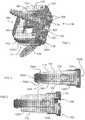
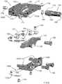
FIG. 1 depicts a spacer of the disclosure, together with three mounted bone screws;FIG. 2 depicts the spacer ofFIG. 1 , in a compressed or reduced height configuration;FIG. 3 depicts the spacer ofFIG. 1 , in an expanded or increased height configuration;FIG. 4 depicts a carriage and frame of the spacer ofFIG. 1 ;FIG. 5 depicts an endplate of the spacer ofFIG. 1 ;FIG. 6 depicts a cross-section of the spacer ofFIG. 2 ;FIG. 7 depicts a cross-section of the spacer ofFIG. 3 ;FIG. 8 depicts an exploded view of the spacer ofFIG. 1 ;FIG. 9 depicts a diagrammatic view of aspects of a spacer in accordance with the disclosure, in a reduced height configuration;FIG. 10 depicts a the spacer ofFIG. 9 , in an expanded height configuration; andFIG. 11 depicts the spacer ofFIG. 1 , implanted between adjacent vertebrae.- As required, detailed embodiments are disclosed herein; the invention is defined in the appended claims, however, it is to be understood that the disclosed embodiments are merely examples and that the systems and methods described below can be embodied in various forms. Therefore, specific structural and functional details disclosed herein are not to be interpreted as limiting, but merely as a basis for the claims and as a representative basis for teaching one skilled in the art to variously employ the present subject matter in virtually any appropriately detailed structure and function. Further, the terms and phrases used herein are not intended to be limiting, but rather, to provide an understandable description of the concepts.
- The terms "a" or "an", as used herein, are defined as one or more than one. The term plurality, as used herein, is defined as two or more than two. The term another, as used herein, is defined as at least a second or more. The terms "including" and "having," as used herein, are defined as comprising (i.e., open language).
- With reference to
FIGS. 1-3 ,implant 100 is operative, when positioned between adjacent bones of a joint, such as forexample vertebrae 10, 12 (shown inFIG. 11 ), to stabilize a joint formed by adjacent vertebrae.Implant 100 has a collapsed state or height, illustrated inFIG. 2 , and an expanded state or height, illustrated inFIG. 3 .Implants 100 of the disclosure may be inset into the intervertebral disc space at a collapsed height, and then expand axially (superior/inferior) to restore height loss in the disc space. The implant provides distraction as well as achieves optimal height restoration. When inserted in a collapsed stated,implants 100 reduce impaction to tissue in the joint space during insertion, and form the least visually blocking or obstructing profile. Implant 100 includes twoseparable endplates endplate other projections 116 which can penetrate body tissue to reduce a likelihood of migration ofimplant 100 after implantation.Implant 100 is further secured with one ormore bone screws 300, which pass throughbone screw socket 118 withinimplant 100, and into body tissue of the patient. In the embodiment illustrated inFIGS. 1-3 , threesockets 118 for three bone screws are provided, thebone screws 300 further retained in connection withimplant 100 by blockingfasteners 120.Bone screw 300 can be a polyaxial screw, andsockets 118 correspondingly shaped, wherebybone screw 300 may be inserted into body tissue at an optimal angle with respect toimplant 100, whereby optimal purchase may be obtained, or certain body tissue may be avoided.Endplates actuator 150 operable to change a relative relationship ofendplates frame 152 rotatably supporting anactuator screw 154, and amoveable carriage 156. As actuator screw 154 rotates withinframe 152,carriage 156 slides withinframe 152, driven by cooperation between threads 158 (FIG. 8 ) uponactuator screw 152, andmating threads 160 withincarriage 156. In the embodiment ofFIGS. 1-3 ,endplates portion portion portions Metallic portions implant 100 which are under relatively greater stress, for example portions through which a fastener may pass to anchorimplant 100 within the body. Whileportions - With reference to
FIG. 2 , it may be seen thatimplant 100 is in a compressed state, having a lower height relative to an expanded state, as shown inFIG. 3 . A functioning ofdevice 100 may be best understood with reference toFIGS. 9-10 , which correlate withFIGS. 2-3 , respectively, but which present a simplified view having certain elements eliminated or exaggerated, to ease understanding.Endplates channels open ramp ramps carriage 156. While two mating channels and ramps are illustrated for eachendplate channels actuator screw 152 in an opposite direction to expansion can driveendplates endplates carriage 156 and anendplate Carriage 156 is supported byframe 152 by lateral engagement means, in this embodiment twosupport screws 174 engaged withcarriage 156, and passable throughrespective channels 176 formed inframe 152.Distal end 172 ofactuator screw 154 provides additional support forcarriage 156.Actuator screw 154 is supported by aset screw 178, which passes through and is rotatably supported withinframe 152.- An
actuator access port 180 permits passage of a tool, for example a hex driver (not shown), into engagement with aproximal end 182 ofactuator screw 152. Asactuator screw 152 is turned,distal end 172 bears against athrust washer 184, and an end portion offrame 152. Asactuator screw 152,carriage 156 is driven along actuator screw by interaction ofthreads carriage 156 moves,endplates ramps spacer 100.Endplates carriage 156 by abutting against anend portion 186 offrame 152. In a given orientation, one ofendplate implant 100 may, in some embodiments, be implantable in either of opposite orientations, and therefore designations of upper and lower are provided for ease of understanding, only. It should be understood that only one ofendplate endplate 112 may be attached toframe 152. FIG. 11 illustrates aspacer 100 of the disclosure implanted betweenadjacent vertebrae Frame 152 defines a distal orleading end 152A which is inserted first into the body, and a proximal or trailingend 152B which passes last into the body, the distal and proximal ends defining a longitudinal axis extending therebetween.Spacer 100 can be inserted into the body, and into a position between vertebrae, using minimally invasive methods, for example using a small incision, andspacer 100 may be passed through a cannula or other structure which maintains a pathway through body tissue.Spacer 100 may be inserted into the spinal column through any approach, including anterior, anterolateral, lateral, or posterolateral. A portion of the disc annulus, and nucleus pulposus may be removed in order to form a space into which spacer 100 may be inserted. Whenspacer 100 is in a compressed, or reduced height configuration, dovetail guides 200, 202 can be provided to foster maintenance of a relative orientation of upper and lower endplates during insertion or removal ofdevice 100.Spacer 100 can be inserted configured to have a lower height profile, as shown inFIG. 2 , whereby an extent of distraction of body tissue may be reduced during insertion. Moreover, to the extent that spacer 100 is used to open a pathway towards an implantation site, trauma to adjacent tissue is reduced relative to inserting a spacer having a final height profile. Oncespacer 100 is positioned between adjacent vertebrae, actuator screw is rotated by a tool. The tool may be positioned entirely within the body, or can extend from in interior of the body to outside the body, for example having a driving tip at one end and having a handle at an opposite end, with a shaft extending into the body between each end.- Once
actuator screw 154 has been rotated toseparate endplates 110, 112 a desired amount, the tool is removed. At this point,actuator screw 154 may be secured in place, for example using a mechanical block, or an adhesive, to prevent unintended rotation ofactuator screw 154. Ascarriage 156 is slideably moved by rotation ofactuator screw 154, aramp channel endplate ramp carriage 156, to cause the endplate to move along an axis transverse to the longitudinal axis of the frame, to increase a height of the spacer. Rotation ofactuator screw 154 in an opposite direction causes movement along an axis transverse to the longitudinal axis of the frame to decrease a height of the spacer. - Polymeric insets, or a polymeric square nut, for example PEEK, can be provided, engageable with
threads 158 or other portion ofactuator screw 152, to provide additional friction to prevent height loss under load, particularly under cyclic loading. Similarly, once bone screws 300 have been inserted, blockingelements 196 may be rotated to extend over an end ofbone screw head 302, preventingscrew 300 from backing out. A similar mechanical block (not shown) may be provided foractuator screw 154. - With reference to
FIGS. 1-3 ,5-8 , it may be seen that asocket 118 for apolyaxial screw head 302 can be formed entirely within one of upper orlower endplate endplate spacer 100 has been expanded to a final height, the proportions of an interior ofsocket 118 are correct or substantially correct for retainingscrew head 302. For example, inFIG. 8 ,metallic portion 124 forms anupper portion 190 ofsocket 118, and matingmetallic portion 124A forms alower portion 192 ofsocket 118. In the embodiment illustrated in the figures, there are threesockets 118, and all are formed of upper and lower portions. However, there may be more orfewer sockets 118, and one or more sockets may be formed entirely in an upper or lower endplate. - In an embodiment,
spacer 100 of the disclosure provides an actuator that translates relative to the body by means of a threadedactuator screw 154.Ramps carrier 152 mate withchannels ramps 166, onendplates carriage 152 causesendplates implant 100 along an S/I axis with respect to the body. There can be dovetail guides that captureendplates - Assembly screws 162 fasten endplates made of dissimilar materials, for example PEEK
polymeric portions metallic portions washer 184 is used between the threadedactuator screw 154 andframe 152 to minimize friction during expansion ofimplant 100. Support screws 174 andchannels 176 cooperate to form side or lateral stabilizers, and setscrew 178 supports a nose or leading end ofcarriage 152. Additionally, cooperating slots and projections (not shown) incarriage 156 andframe 152 can be provided for further relative guidance and stability. - In one embodiment, three
bone screws 300 are used to provide fixation into adjacent vertebral bodies, twoscrews 300 passing throughimplant 100 and into one vertebra, and onescrew 300 passing throughimplant 100 into another vertebra, although other combinations may be used. Bone screws 300 can have spherical or otherwise curved heads, facilitating insertion at a desired angle, or may be provided to mate withsocket 118 in a fixed orientation, particularly depending on a diameter of a neck portion ofscrew 300. Camstyle blocking fasteners 120 can be used to block bone screws 300 from backing out after being inserted. - Implants of the disclosure enable a continuous expansion and retraction over a range of displacements according to predetermined dimensions of a
specific implant 100 design. This provides the ability to distract vertebral bodies to a desired height, but also to collapse theimplant 100 for repositioning, if therapeutically advantageous for the patient.Endplates Implant 100 may be used to distract, or force bones of a joint apart, or may be used to maintain a separation of bones created by other means, for example a retractor. Implant 100 may be fabricated using any biocompatible materials known to one skilled in the art, having sufficient strength, flexibility, resiliency, and durability for the patient, and for the term during which the device is to be implanted. Examples include but are not limited to metal, such as, for example titanium and chromium alloys; polymers, including for example, PEEK or high molecular weight polyethylene (HMWPE); and ceramics. There are many other biocompatible materials which may be used, including other plastics and metals, as well as fabrication using living or preserved tissue, including autograft, allograft, and xenograft material.- Portions or all of the implant may be radiopaque or radiolucent, or materials having such properties may be added or incorporated into the implant to improve imaging of the device during and after implantation.
- For example,
metallic portions endplates Polymeric portions implant 100. For example,polymeric portions - In accordance with the invention, implants of various sizes may be provided to best fit the anatomy of the patient. Components of matching or divergent sizes may be assembled during the implantation procedure by a medical practitioner as best meets the therapeutic needs of the patient, the assembly inserted within the body using an insertion tool. Implants of the invention may also be provided with an overall angular geometry, for example an angular mating disposition of
endplates plates Implants 100 may be implanted within any level of the spine, and may also be implanted in other joints of the body, including joints of the hand, wrist, elbow, shoulder, hip, knee, ankle, or foot. - In accordance with the invention, a
single implant 100 may be used, to provide stabilization for a weakened joint or joint portion. Alternatively, two, three, ormore implants 100 may be used, at a single joint level, or in multiple joints. Moreover,implants 100 may be combined with other stabilizing means. - Additionally,
implant 100 may be fabricated using material that biodegrades in the body during a therapeutically advantageous time interval, for example after sufficient bone ingrowth has taken place. Further,implant 100 is advantageously provided with smooth and or rounded exterior surfaces, which reduce a potential for deleterious mechanical effects on neighboring tissues. - Any surface or component of the invention may be coated with or impregnated with therapeutic agents, including bone growth, healing, antimicrobial, or drug materials, which may be released at a therapeutic rate, using methods known to those skilled in the art.
- Devices of the disclosure provide for adjacent vertebrae to be supported during flexion/extension, lateral bending, and axial rotation. In one embodiment,
implant 100 is indicated for spinal arthroplasty in treating skeletally mature patients with degenerative disc disease, primary or recurrent disc herniation, spinal stenosis, or spondylosis in the lumbosacral spine (LI-SI). Degenerative disc disease is advantageously defined as discogenic back pain with degeneration of the disc confirmed by patient history and radiographic studies, with or without leg (radicular) pain. Patients are advantageously treated, for example, who may have spondylolisthesis up to Grade 1 at the involved level. Thesurgery position implant 100 may be performed through an Anterior, Anterolateral, Posterolateral, and/or Lateral approach. - In a typical embodiment,
implant 100 has a uncompressed height, before insertion, of 12 to 18mm, and may advantageously be provided in cross-sections of 23x32mm, 26x38mm and 26x42mm, with 4, 8, 12, or 16 degree lordotic angles, although these are only representative sizes, and substantially smaller or larger sizes can be therapeutically beneficial. In one embodiment aspacer 100 in accordance with the instant disclosure is sized to be inserted using an MIS approach (a reduced incision size, with fewer and shorter cuts through body tissue). Implant 100 may advantageously be used in combination with other known or hereinafter developed forms of stabilization or fixation, including for example rods and plates.
Claims (14)
- A joint spacer (100) for therapeutically maintaining a separation of bones of a joint, comprising:a frame (152) having distal and proximal ends defining a longitudinal axis extending therebetween;a carriage (156) slideably retained within said frame (152) and having at least one ramped surface (170), said carriage (156) further including a threaded portion (160),an actuator screw (154) threadably engaged with said carriage threaded portion (160), said actuator screw configured to bear against said frame (152) to cause said carriage (156) to slideably move within said frame when said actuator screw (154) is rotated;a first endplate (110) configured to engage a first bone of the joint, and having at least one ramped surface (164) mateable with said at least one carriage ramped surface (170), whereby when said carriage (156) is slideably moveable by rotation of said actuator screw (154), said at least one endplate ramped surface (164) slideable against said at least one carriage ramped surface (170) to cause said first endplate (110) to move along an axis transverse to said longitudinal axis to increase a height of the spacer (100);a second endplate (112) configured to engage a second bone of the joint;a fastener (300), wherein the first endplate (110) includes at least one aperture (118) through which the fastener (300) passes to secure the first endplate (110) to the first bone of the joint andcharacterized in thatthe carriage (156) is supported by the frame (152) by lateral engagement means in the form of two support screws (174) engaged with the carriage (156) passable through respective channels (176) formed in the frame (152).
- The joint spacer of claim 1, wherein said carriage (156) includes at least one additional ramped surface (170A), and said second endplate (112) includes at least one ramped surface (164A) mateable with said at least one additional ramped surface (170A) of said carriage (156), whereby when said carriage (156) is slideably moved by rotation of said actuator screw (154), said at least one second endplate ramped surface (164A) slides against said at least one additional carriage ramped surface (170A) to cause said second endplate (112) to move along an axis transverse to said longitudinal axis to increase a height of the spacer (100).
- The joint spacer of claim 1, said first endplate (110) configured to abut said frame (152) as said first endplate (110) is moved along an axis transverse to said longitudinal axis, whereby said first endplate (110) moves substantially only along an axis transverse to said longitudinal axis.
- The joint spacer of claim 1, further including a blocking mechanism (120) to prevent backing out of the fastener (300) passed through said first endplate (110).
- The joint spacer of claim 1, wherein said first endplate (110) includes one or more projections (116) configured to engage bone of the joint when the implant (100) is positioned between bones of the joint.
- The joint spacer of claim 1, wherein at least one of said first and second endplates (110, 112) is composed of two interconnected portions of dissimilar materials.
- The joint spacer of claim 6, wherein one of said dissimilar materials is metallic and includes the at least one aperture (118) through which the fastener (300) may be passed to attach the implant (100) to a bone of the joint.
- The joint spacer of claim 1, wherein one dissimilar material is polymeric, and another dissimilar material is metallic.
- The joint spacer of claim 1, wherein said carriage (156) is slideably supported by said actuator screw (154) and by the two support screw (174) extending from said carriage (156) to said frame (152).
- The joint spacer of claim 1, further including a thrust washer (184) interposed between said actuator screw (154) and said frame (152).
- The joint spacer of claim 1, further including a polymeric material configured to press against said actuator screw (154) to reduce a potential for unintended rotation of said actuator screw (154).
- The joint spacer of claim1, further including an aperture formed in part by said first endplate (110), and in part by said second endplate (112), said aperture sized and dimensioned to rotatably support a bone screw when said first endplate (110) has been moved a distance along the axis transverse to said longitudinal axis.
- The joint spacer of claim 1, further including a dovetail connection formed between said frame (152) and said first endplate (110) when said first endplate (110) is configured to abut against said frame (152).
- The joint spacer of claim 1, wherein the actuator screw (154) is supported by a set screw (178), which passes through and is rotatably supported within the frame (152).
Applications Claiming Priority (2)
| Application Number | Priority Date | Filing Date | Title |
|---|---|---|---|
| US13/775,731US10117754B2 (en) | 2013-02-25 | 2013-02-25 | Expandable intervertebral implant |
| PCT/US2014/018191WO2014130989A1 (en) | 2013-02-25 | 2014-02-25 | Expandable intervertebral implant |
Publications (3)
| Publication Number | Publication Date |
|---|---|
| EP2958525A1 EP2958525A1 (en) | 2015-12-30 |
| EP2958525A4 EP2958525A4 (en) | 2016-03-09 |
| EP2958525B1true EP2958525B1 (en) | 2019-09-11 |
Family
ID=51388936
Family Applications (1)
| Application Number | Title | Priority Date | Filing Date |
|---|---|---|---|
| EP14754914.1AActiveEP2958525B1 (en) | 2013-02-25 | 2014-02-25 | Expandable intervertebral implant |
Country Status (4)
| Country | Link |
|---|---|
| US (5) | US10117754B2 (en) |
| EP (1) | EP2958525B1 (en) |
| JP (1) | JP6525893B2 (en) |
| WO (1) | WO2014130989A1 (en) |
Cited By (1)
| Publication number | Priority date | Publication date | Assignee | Title |
|---|---|---|---|---|
| US12318307B2 (en) | 2021-07-16 | 2025-06-03 | Blue Ocean Spine Gmbh | Adjustable spinal implants, associated instruments and methods |
Families Citing this family (78)
| Publication number | Priority date | Publication date | Assignee | Title |
|---|---|---|---|---|
| US6793678B2 (en) | 2002-06-27 | 2004-09-21 | Depuy Acromed, Inc. | Prosthetic intervertebral motion disc having dampening |
| WO2008070863A2 (en) | 2006-12-07 | 2008-06-12 | Interventional Spine, Inc. | Intervertebral implant |
| US8900307B2 (en) | 2007-06-26 | 2014-12-02 | DePuy Synthes Products, LLC | Highly lordosed fusion cage |
| EP2237748B1 (en) | 2008-01-17 | 2012-09-05 | Synthes GmbH | An expandable intervertebral implant |
| US8936641B2 (en) | 2008-04-05 | 2015-01-20 | DePuy Synthes Products, LLC | Expandable intervertebral implant |
| US11224521B2 (en) | 2008-06-06 | 2022-01-18 | Providence Medical Technology, Inc. | Cervical distraction/implant delivery device |
| US9526620B2 (en) | 2009-03-30 | 2016-12-27 | DePuy Synthes Products, Inc. | Zero profile spinal fusion cage |
| KR101687435B1 (en) | 2009-07-06 | 2016-12-19 | 신세스 게엠바하 | Expandable fixation assemblies |
| US8979860B2 (en) | 2010-06-24 | 2015-03-17 | DePuy Synthes Products. LLC | Enhanced cage insertion device |
| US8623091B2 (en) | 2010-06-29 | 2014-01-07 | DePuy Synthes Products, LLC | Distractible intervertebral implant |
| US20120078372A1 (en) | 2010-09-23 | 2012-03-29 | Thomas Gamache | Novel implant inserter having a laterally-extending dovetail engagement feature |
| US9248028B2 (en) | 2011-09-16 | 2016-02-02 | DePuy Synthes Products, Inc. | Removable, bone-securing cover plate for intervertebral fusion cage |
| EP2877127B1 (en) | 2012-07-26 | 2019-08-21 | Synthes GmbH | Expandable implant |
| US8663332B1 (en) | 2012-12-13 | 2014-03-04 | Ouroboros Medical, Inc. | Bone graft distribution system |
| US10117754B2 (en)* | 2013-02-25 | 2018-11-06 | Globus Medical, Inc. | Expandable intervertebral implant |
| US9717601B2 (en) | 2013-02-28 | 2017-08-01 | DePuy Synthes Products, Inc. | Expandable intervertebral implant, system, kit and method |
| US9522070B2 (en) | 2013-03-07 | 2016-12-20 | Interventional Spine, Inc. | Intervertebral implant |
| US12193948B2 (en) | 2013-03-13 | 2025-01-14 | Life Spine, Inc. | Expandable implant assembly |
| US10426632B2 (en) | 2013-03-13 | 2019-10-01 | Life Spine, Inc. | Expandable spinal interbody assembly |
| US11304818B2 (en) | 2013-03-13 | 2022-04-19 | Life Spine, Inc. | Expandable spinal interbody assembly |
| US9186259B2 (en) | 2013-09-09 | 2015-11-17 | Ouroboros Medical, Inc. | Expandable trials |
| US11160666B2 (en)* | 2014-05-15 | 2021-11-02 | Globus Medical, Inc. | Laterally insertable intervertebral spinal implant |
| US9968461B2 (en)* | 2014-05-15 | 2018-05-15 | Globus Medical, Inc. | Standalone interbody implants |
| US9486327B2 (en)* | 2014-05-15 | 2016-11-08 | Globus Medical, Inc. | Standalone interbody implants |
| US9060876B1 (en)* | 2015-01-20 | 2015-06-23 | Ouroboros Medical, Inc. | Stabilized intervertebral scaffolding systems |
| US11426290B2 (en) | 2015-03-06 | 2022-08-30 | DePuy Synthes Products, Inc. | Expandable intervertebral implant, system, kit and method |
| US9913727B2 (en) | 2015-07-02 | 2018-03-13 | Medos International Sarl | Expandable implant |
| US11510788B2 (en) | 2016-06-28 | 2022-11-29 | Eit Emerging Implant Technologies Gmbh | Expandable, angularly adjustable intervertebral cages |
| EP3474784A2 (en) | 2016-06-28 | 2019-05-01 | Eit Emerging Implant Technologies GmbH | Expandable and angularly adjustable intervertebral cages with articulating joint |
| US9883953B1 (en) | 2016-09-21 | 2018-02-06 | Integrity Implants Inc. | Stabilized laterovertically-expanding fusion cage systems with tensioner |
| US10537436B2 (en) | 2016-11-01 | 2020-01-21 | DePuy Synthes Products, Inc. | Curved expandable cage |
| US10888433B2 (en) | 2016-12-14 | 2021-01-12 | DePuy Synthes Products, Inc. | Intervertebral implant inserter and related methods |
| JP7085554B2 (en) | 2017-01-10 | 2022-06-16 | インテグリティ インプランツ インコーポレイテッド | Deployable intervertebral fusion device |
| US10398563B2 (en) | 2017-05-08 | 2019-09-03 | Medos International Sarl | Expandable cage |
| US11344424B2 (en) | 2017-06-14 | 2022-05-31 | Medos International Sarl | Expandable intervertebral implant and related methods |
| US10940016B2 (en) | 2017-07-05 | 2021-03-09 | Medos International Sarl | Expandable intervertebral fusion cage |
| US11896494B2 (en) | 2017-07-10 | 2024-02-13 | Life Spine, Inc. | Expandable implant assembly |
| CN111031969A (en) | 2017-07-24 | 2020-04-17 | 整体植入有限公司 | Surgical implants and related methods |
| US10709578B2 (en) | 2017-08-25 | 2020-07-14 | Integrity Implants Inc. | Surgical biologics delivery system and related methods |
| US11806250B2 (en) | 2018-02-22 | 2023-11-07 | Warsaw Orthopedic, Inc. | Expandable spinal implant system and method of using same |
| JP7572857B2 (en) | 2018-03-01 | 2024-10-24 | インテグリティ インプランツ インコーポレイテッド | Expandable Fusion Device with Independent Deployment System |
| US11446156B2 (en) | 2018-10-25 | 2022-09-20 | Medos International Sarl | Expandable intervertebral implant, inserter instrument, and related methods |
| US11382764B2 (en) | 2019-06-10 | 2022-07-12 | Life Spine, Inc. | Expandable implant assembly with compression features |
| US12042395B2 (en) | 2019-06-11 | 2024-07-23 | Life Spine, Inc. | Expandable implant assembly |
| US11426286B2 (en) | 2020-03-06 | 2022-08-30 | Eit Emerging Implant Technologies Gmbh | Expandable intervertebral implant |
| US11382761B2 (en) | 2020-04-11 | 2022-07-12 | Neurostructures, Inc. | Expandable interbody spacer |
| US11857432B2 (en) | 2020-04-13 | 2024-01-02 | Life Spine, Inc. | Expandable implant assembly |
| US11602439B2 (en) | 2020-04-16 | 2023-03-14 | Life Spine, Inc. | Expandable implant assembly |
| US12336917B2 (en) | 2020-05-15 | 2025-06-24 | Life Spine, Inc. | Steerable implant assembly |
| US11304817B2 (en) | 2020-06-05 | 2022-04-19 | Neurostructures, Inc. | Expandable interbody spacer |
| US11602440B2 (en) | 2020-06-25 | 2023-03-14 | Life Spine, Inc. | Expandable implant assembly |
| EP4171448A4 (en) | 2020-07-20 | 2025-02-12 | Integrity Implants Inc. | EXPANDABLE FUSION DEVICE WITH INDEPENDENT EXPANSION SYSTEMS |
| CN111839830B (en)* | 2020-07-23 | 2021-09-14 | 山东第一医科大学附属省立医院(山东省立医院) | Fixable intervertebral fusion cage under self-guiding distraction mirror |
| US11554020B2 (en) | 2020-09-08 | 2023-01-17 | Life Spine, Inc. | Expandable implant with pivoting control assembly |
| US11638653B2 (en) | 2020-11-05 | 2023-05-02 | Warsaw Orthopedic, Inc. | Surgery instruments with a movable handle |
| US11395743B1 (en) | 2021-05-04 | 2022-07-26 | Warsaw Orthopedic, Inc. | Externally driven expandable interbody and related methods |
| US11963881B2 (en) | 2020-11-05 | 2024-04-23 | Warsaw Orthopedic, Inc. | Expandable inter-body device, system, and method |
| US11285014B1 (en) | 2020-11-05 | 2022-03-29 | Warsaw Orthopedic, Inc. | Expandable inter-body device, system, and method |
| US12318308B2 (en) | 2020-11-05 | 2025-06-03 | Warsaw Orthopedic, Inc. | Dual expandable inter-body device |
| US11517363B2 (en) | 2020-11-05 | 2022-12-06 | Warsaw Orthopedic, Inc. | Screw driver and complimentary screws |
| US12239544B2 (en) | 2020-11-05 | 2025-03-04 | Warsaw Orthopedic, Inc. | Rhomboid shaped implants |
| US11833059B2 (en) | 2020-11-05 | 2023-12-05 | Warsaw Orthopedic, Inc. | Expandable inter-body device, expandable plate system, and associated methods |
| US12171439B2 (en) | 2020-11-05 | 2024-12-24 | Warsaw Orthopedic, Inc. | Protected drill |
| US11291554B1 (en) | 2021-05-03 | 2022-04-05 | Medtronic, Inc. | Unibody dual expanding interbody implant |
| US11376134B1 (en) | 2020-11-05 | 2022-07-05 | Warsaw Orthopedic, Inc. | Dual expanding spinal implant, system, and method of use |
| US12121453B2 (en) | 2020-11-05 | 2024-10-22 | Warsaw Orthopedic, Inc. | Dual wedge expandable implant with eyelets, system, and method of use |
| US11517443B2 (en) | 2020-11-05 | 2022-12-06 | Warsaw Orthopedic, Inc. | Dual wedge expandable implant, system and method of use |
| US11717419B2 (en) | 2020-12-10 | 2023-08-08 | Neurostructures, Inc. | Expandable interbody spacer |
| US11850160B2 (en) | 2021-03-26 | 2023-12-26 | Medos International Sarl | Expandable lordotic intervertebral fusion cage |
| US11752009B2 (en) | 2021-04-06 | 2023-09-12 | Medos International Sarl | Expandable intervertebral fusion cage |
| US12295865B2 (en) | 2021-06-24 | 2025-05-13 | Warsaw Orthopedic, Inc. | Expandable interbody implant and corresponding inserter |
| WO2022271280A1 (en) | 2021-06-24 | 2022-12-29 | Warsaw Orthopedic, Inc. | Expandable interbody implant and corresponding surgical tool |
| US11612499B2 (en) | 2021-06-24 | 2023-03-28 | Warsaw Orthopedic, Inc. | Expandable interbody implant |
| US12268614B2 (en) | 2021-06-24 | 2025-04-08 | Warsaw Orthopedic, Inc. | Interbody implant with adjusting shims |
| US11730608B2 (en) | 2021-07-13 | 2023-08-22 | Warsaw Orthopedic, Inc. | Monoblock expandable interbody implant |
| US12011362B2 (en) | 2021-08-05 | 2024-06-18 | Warsaw Orthopedic, Inc. | Breakaway endplate portions for implant revision |
| US11850163B2 (en) | 2022-02-01 | 2023-12-26 | Warsaw Orthopedic, Inc. | Interbody implant with adjusting shims |
| US12090064B2 (en) | 2022-03-01 | 2024-09-17 | Medos International Sarl | Stabilization members for expandable intervertebral implants, and related systems and methods |
Family Cites Families (290)
| Publication number | Priority date | Publication date | Assignee | Title |
|---|---|---|---|---|
| CA1146301A (en) | 1980-06-13 | 1983-05-17 | J. David Kuntz | Intervertebral disc prosthesis |
| US4636217A (en)* | 1985-04-23 | 1987-01-13 | Regents Of The University Of Minnesota | Anterior spinal implant |
| US4599086A (en) | 1985-06-07 | 1986-07-08 | Doty James R | Spine stabilization device and method |
| SU1424826A1 (en) | 1986-05-22 | 1988-09-23 | Белорусский научно-исследовательский институт травматологии и ортопедии | Fixative for spinal column |
| GB8620937D0 (en) | 1986-08-29 | 1986-10-08 | Shepperd J A N | Spinal implant |
| US4863477A (en) | 1987-05-12 | 1989-09-05 | Monson Gary L | Synthetic intervertebral disc prosthesis |
| CA1333209C (en) | 1988-06-28 | 1994-11-29 | Gary Karlin Michelson | Artificial spinal fusion implants |
| DE4012622C1 (en) | 1990-04-20 | 1991-07-18 | Eska Medical Luebeck Medizintechnik Gmbh & Co, 2400 Luebeck, De | Two-part metal vertebra implant - has parts locked by two toothed racks, pre-stressed by elastic cushion between both implant parts |
| AT394307B (en) | 1990-07-24 | 1992-03-10 | Mohamed Ibrahim Dr Rasheed | SPINE PROSTHESIS |
| US5390683A (en) | 1991-02-22 | 1995-02-21 | Pisharodi; Madhavan | Spinal implantation methods utilizing a middle expandable implant |
| US5123926A (en) | 1991-02-22 | 1992-06-23 | Madhavan Pisharodi | Artificial spinal prosthesis |
| DE4128332A1 (en) | 1991-08-27 | 1993-03-04 | Man Ceramics Gmbh | SPINE BONE REPLACEMENT |
| US5290312A (en) | 1991-09-03 | 1994-03-01 | Alphatec | Artificial vertebral body |
| FR2692952B1 (en) | 1992-06-25 | 1996-04-05 | Psi | IMPROVED SHOCK ABSORBER WITH MOVEMENT LIMIT. |
| DE69320593T2 (en) | 1992-11-25 | 1999-03-04 | Codman & Shurtleff, Inc., Randolph, Mass. | Bone plate system |
| US5676701A (en) | 1993-01-14 | 1997-10-14 | Smith & Nephew, Inc. | Low wear artificial spinal disc |
| EP0610837B1 (en) | 1993-02-09 | 2001-09-05 | Acromed Corporation | Spine disc |
| US6066175A (en) | 1993-02-16 | 2000-05-23 | Henderson; Fraser C. | Fusion stabilization chamber |
| US5645596A (en) | 1993-07-07 | 1997-07-08 | Asahi Kogaku Kogyo Kabushiki Kaisha | Ceramic vertebrae prosthesis |
| DE4327054C1 (en) | 1993-08-12 | 1995-04-13 | Schaefer Micomed Gmbh | Ventral intervertebral implant |
| US5458641A (en) | 1993-09-08 | 1995-10-17 | Ramirez Jimenez; Juan J. | Vertebral body prosthesis |
| US5397364A (en) | 1993-10-12 | 1995-03-14 | Danek Medical, Inc. | Anterior interbody fusion device |
| FR2715293B1 (en) | 1994-01-26 | 1996-03-22 | Biomat | Vertebral interbody fusion cage. |
| US5697977A (en) | 1994-03-18 | 1997-12-16 | Pisharodi; Madhavan | Method and apparatus for spondylolisthesis reduction |
| EP0751753B1 (en) | 1994-03-23 | 1997-10-22 | Schnorrenberg Chirurgiemechanik GmbH | Positioning and support device for the spinal column |
| DE4423257C2 (en) | 1994-07-02 | 2001-07-12 | Ulrich Heinrich | Implant to be inserted between the vertebral body of the spine as a placeholder |
| FR2727003B1 (en) | 1994-11-18 | 1997-04-18 | Euros Sa | ANTERIOR STABILIZATION DEVICE OF THE LOMBO-SACRE SPINE |
| US5665122A (en) | 1995-01-31 | 1997-09-09 | Kambin; Parviz | Expandable intervertebral cage and surgical method |
| US6206922B1 (en) | 1995-03-27 | 2001-03-27 | Sdgi Holdings, Inc. | Methods and instruments for interbody fusion |
| CA2242645A1 (en) | 1995-12-08 | 1997-06-12 | Robert S. Bray, Jr. | Anterior stabilization device |
| FR2742653B1 (en) | 1995-12-21 | 1998-02-27 | Colorado | INTERSOMATIC VERTEBRAL CAGE |
| US5653763A (en) | 1996-03-29 | 1997-08-05 | Fastenetix, L.L.C. | Intervertebral space shape conforming cage device |
| US7959652B2 (en) | 2005-04-18 | 2011-06-14 | Kyphon Sarl | Interspinous process implant having deployable wings and method of implantation |
| US6139550A (en) | 1997-02-11 | 2000-10-31 | Michelson; Gary K. | Skeletal plating system |
| US6039761A (en) | 1997-02-12 | 2000-03-21 | Li Medical Technologies, Inc. | Intervertebral spacer and tool and method for emplacement thereof |
| US5861041A (en) | 1997-04-07 | 1999-01-19 | Arthit Sitiso | Intervertebral disk prosthesis and method of making the same |
| US6641614B1 (en) | 1997-05-01 | 2003-11-04 | Spinal Concepts, Inc. | Multi-variable-height fusion device |
| US6045579A (en) | 1997-05-01 | 2000-04-04 | Spinal Concepts, Inc. | Adjustable height fusion device |
| US6482233B1 (en) | 1998-01-29 | 2002-11-19 | Synthes(U.S.A.) | Prosthetic interbody spacer |
| FR2774280B1 (en)* | 1998-01-30 | 2000-07-28 | Dimso Sa | IMPLANT TO REPLACE A VERTEBRA |
| DE19807236C2 (en) | 1998-02-20 | 2000-06-21 | Biedermann Motech Gmbh | Intervertebral implant |
| US6258089B1 (en) | 1998-05-19 | 2001-07-10 | Alphatec Manufacturing, Inc. | Anterior cervical plate and fixation system |
| US6126689A (en) | 1998-06-15 | 2000-10-03 | Expanding Concepts, L.L.C. | Collapsible and expandable interbody fusion device |
| FR2794968B1 (en) | 1999-06-17 | 2002-09-06 | Dimso Sa | INTERSOMATIC RACHIDIAN IMPLANT WITH HIGHLIGHTS |
| DE69917026T2 (en) | 1998-06-23 | 2004-10-28 | Dimso Distribution Medicale Du Sud Ouest | INTERSOMATIC SPINE IMPLANT WITH ANCHORING ELEMENTS |
| WO2000004851A1 (en) | 1998-07-22 | 2000-02-03 | Spinal Dynamics Corporation | Threaded cylindrical multidiscoid single or multiple array disc prosthesis |
| DK1100417T3 (en) | 1998-08-03 | 2004-08-02 | Synthes Ag | Intervertebral allograft spacer |
| US6099531A (en) | 1998-08-20 | 2000-08-08 | Bonutti; Peter M. | Changing relationship between bones |
| FR2782632B1 (en) | 1998-08-28 | 2000-12-29 | Materiel Orthopedique En Abreg | EXPANSIBLE INTERSOMATIC FUSION CAGE |
| US6113637A (en) | 1998-10-22 | 2000-09-05 | Sofamor Danek Holdings, Inc. | Artificial intervertebral joint permitting translational and rotational motion |
| US6156037A (en) | 1998-10-28 | 2000-12-05 | Sdgi Holdings, Inc. | Anterior lateral spine cage-plate fixation device and technique |
| US6200347B1 (en) | 1999-01-05 | 2001-03-13 | Lifenet | Composite bone graft, method of making and using same |
| FR2788686B1 (en) | 1999-01-26 | 2001-06-08 | Scient X | INTERSOMATIC IMPLANT WITH SAGITTAL INTRODUCTION SUITABLE FOR LATERAL SHIFT IN THE FRONTAL PLANE |
| AU4988700A (en) | 1999-05-05 | 2000-11-17 | Gary K. Michelson | Spinal fusion implants with opposed locking screws |
| US7094239B1 (en) | 1999-05-05 | 2006-08-22 | Sdgi Holdings, Inc. | Screws of cortical bone and method of manufacture thereof |
| AU770261B2 (en) | 1999-06-04 | 2004-02-19 | Warsaw Orthopedic, Inc. | Artificial disc implant |
| US6419705B1 (en) | 1999-06-23 | 2002-07-16 | Sulzer Spine-Tech Inc. | Expandable fusion device and method |
| WO2002009626A1 (en) | 1999-07-26 | 2002-02-07 | Advanced Prosthetic Technologies, Inc. | Improved spinal surgical prosthesis |
| US6231610B1 (en) | 1999-08-25 | 2001-05-15 | Allegiance Corporation | Anterior cervical column support device |
| US7918888B2 (en) | 1999-10-13 | 2011-04-05 | Hamada James S | Spinal fusion instrumentation, implant and method |
| FR2799638B1 (en) | 1999-10-14 | 2002-08-16 | Fred Zacouto | FIXATOR AND VERTEBRAL JOINT |
| US6432106B1 (en) | 1999-11-24 | 2002-08-13 | Depuy Acromed, Inc. | Anterior lumbar interbody fusion cage with locking plate |
| US6827740B1 (en) | 1999-12-08 | 2004-12-07 | Gary K. Michelson | Spinal implant surface configuration |
| US6814756B1 (en) | 2000-02-04 | 2004-11-09 | Gary K. Michelson | Expandable threaded arcuate interbody spinal fusion implant with lordotic configuration during insertion |
| AU2001274821A1 (en) | 2000-06-13 | 2001-12-24 | Gary K. Michelson | Manufactured major long bone ring implant shaped to conform to a prepared intervertebral implantation space |
| US6808537B2 (en) | 2000-07-07 | 2004-10-26 | Gary Karlin Michelson | Expandable implant with interlocking walls |
| US8535378B2 (en) | 2004-05-10 | 2013-09-17 | Roger P. Jackson | Vertebral interbody spacer |
| US6666891B2 (en) | 2000-11-13 | 2003-12-23 | Frank H. Boehm, Jr. | Device and method for lumbar interbody fusion |
| US6443989B1 (en) | 2000-12-04 | 2002-09-03 | Roger P. Jackson | Posterior expandable fusion cage |
| US6773460B2 (en) | 2000-12-05 | 2004-08-10 | Roger P. Jackson | Anterior variable expandable fusion cage |
| FR2817462B1 (en) | 2000-12-05 | 2003-08-08 | Stryker Spine Sa | IN SITU INTERSOMATIC SPINAL IMPLANT WITH HARD PASSAGE POINTS |
| DE10065232C2 (en) | 2000-12-27 | 2002-11-14 | Ulrich Gmbh & Co Kg | Implant for insertion between the vertebral body and surgical instrument for handling the implant |
| US6468311B2 (en) | 2001-01-22 | 2002-10-22 | Sdgi Holdings, Inc. | Modular interbody fusion implant |
| US6972019B2 (en) | 2001-01-23 | 2005-12-06 | Michelson Gary K | Interbody spinal implant with trailing end adapted to receive bone screws |
| WO2002098332A1 (en) | 2001-02-16 | 2002-12-12 | Sulzer Spine-Tech Inc. | Bone implants and methods |
| US6849093B2 (en)* | 2001-03-09 | 2005-02-01 | Gary K. Michelson | Expansion constraining member adapted for use with an expandable interbody spinal fusion implant and method for use thereof |
| US7128760B2 (en) | 2001-03-27 | 2006-10-31 | Warsaw Orthopedic, Inc. | Radially expanding interbody spinal fusion implants, instrumentation, and methods of insertion |
| FR2822674B1 (en) | 2001-04-03 | 2003-06-27 | Scient X | STABILIZED INTERSOMATIC MELTING SYSTEM FOR VERTEBERS |
| US6558424B2 (en) | 2001-06-28 | 2003-05-06 | Depuy Acromed | Modular anatomic fusion device |
| DE10138079B4 (en) | 2001-08-03 | 2004-02-12 | Biedermann Motech Gmbh | Placeholder with variable axial length |
| DE50114038D1 (en) | 2001-08-24 | 2008-07-31 | Zimmer Gmbh | Artificial disc |
| US6648917B2 (en) | 2001-10-17 | 2003-11-18 | Medicinelodge, Inc. | Adjustable bone fusion implant and method |
| US7025787B2 (en) | 2001-11-26 | 2006-04-11 | Sdgi Holdings, Inc. | Implantable joint prosthesis and associated instrumentation |
| US6855167B2 (en) | 2001-12-05 | 2005-02-15 | Osteotech, Inc. | Spinal intervertebral implant, interconnections for such implant and processes for making |
| US7238203B2 (en) | 2001-12-12 | 2007-07-03 | Vita Special Purpose Corporation | Bioactive spinal implants and method of manufacture thereof |
| US6740118B2 (en) | 2002-01-09 | 2004-05-25 | Sdgi Holdings, Inc. | Intervertebral prosthetic joint |
| US6923830B2 (en) | 2002-02-02 | 2005-08-02 | Gary K. Michelson | Spinal fusion implant having deployable bone engaging projections |
| AU2003215099A1 (en) | 2002-02-07 | 2003-09-02 | Ebi, L.P. | Anterior spinal implant |
| AR038680A1 (en) | 2002-02-19 | 2005-01-26 | Synthes Ag | INTERVERTEBRAL IMPLANT |
| US6682563B2 (en) | 2002-03-04 | 2004-01-27 | Michael S. Scharf | Spinal fixation device |
| EP1482877B1 (en) | 2002-03-11 | 2007-05-30 | Spinal Concepts Inc. | Instrumentation for implanting spinal implant devices |
| RU2303422C2 (en) | 2002-03-12 | 2007-07-27 | Сервитек Инк. | Intervertebral prosthesis and system of intervertebral prostheses, in peculiar case, for cervical department of vertebral column |
| US7717959B2 (en)* | 2002-03-30 | 2010-05-18 | Lytton William | Intervertebral device and method of use |
| KR200290058Y1 (en) | 2002-05-11 | 2002-09-26 | 정연문 | Lumbar vertebra fixture |
| US7070598B2 (en) | 2002-06-25 | 2006-07-04 | Sdgi Holdings, Inc. | Minimally invasive expanding spacer and method |
| US20040087947A1 (en)* | 2002-08-28 | 2004-05-06 | Roy Lim | Minimally invasive expanding spacer and method |
| US7018415B1 (en) | 2002-09-23 | 2006-03-28 | Sdgi Holdings, Inc. | Expandable spinal fusion device and methods of promoting spinal fusion |
| US6899735B2 (en) | 2002-10-02 | 2005-05-31 | Sdgi Holdings, Inc. | Modular intervertebral prosthesis system |
| US7323011B2 (en) | 2002-10-18 | 2008-01-29 | Musculoskeletal Transplant Foundation | Cortical and cancellous allograft cervical fusion block |
| US7497859B2 (en) | 2002-10-29 | 2009-03-03 | Kyphon Sarl | Tools for implanting an artificial vertebral disk |
| JP4654125B2 (en) | 2002-10-29 | 2011-03-16 | スパインコア,インコーポレイテッド | Instruments, methods, and functions for use in implanting an artificial disc |
| AU2003287370B2 (en) | 2002-10-31 | 2009-05-07 | Zimmer Spine, Inc. | Movable disc implant |
| FR2846550B1 (en) | 2002-11-05 | 2006-01-13 | Ldr Medical | INTERVERTEBRAL DISC PROSTHESIS |
| US7320708B1 (en) | 2002-11-13 | 2008-01-22 | Sdgi Holdings, Inc. | Cervical interbody device |
| WO2004047689A1 (en) | 2002-11-21 | 2004-06-10 | Sdgi Holdings, Inc. | Systems and techniques for intravertebral spinal stablization with expandable devices |
| US7473276B2 (en) | 2002-12-17 | 2009-01-06 | Synthes (U.S.A.) | Intervertebral implant with joint parts mounted on roller bodies |
| US7828849B2 (en) | 2003-02-03 | 2010-11-09 | Warsaw Orthopedic, Inc. | Expanding interbody implant and articulating inserter and method |
| CA2515247C (en) | 2003-02-06 | 2010-10-05 | Synthes (U.S.A.) | Intervertebral implant |
| US20040176853A1 (en) | 2003-03-05 | 2004-09-09 | Sennett Andrew R. | Apparatus and method for spinal fusion using posteriorly implanted devices |
| US6908484B2 (en) | 2003-03-06 | 2005-06-21 | Spinecore, Inc. | Cervical disc replacement |
| US9278009B2 (en) | 2003-04-21 | 2016-03-08 | Rsb Spine Llc | Spine implants |
| US8613772B2 (en) | 2003-04-21 | 2013-12-24 | Rsb Spine Llc | Lateral mount implant device |
| US8100976B2 (en) | 2003-04-21 | 2012-01-24 | Rsb Spine Llc | Implant subsidence control |
| CA2524066C (en) | 2003-04-28 | 2011-03-15 | Michael Guetlin | Intervertebral implant |
| US7442211B2 (en) | 2003-05-27 | 2008-10-28 | Spinalmotion, Inc. | Intervertebral prosthetic disc |
| US6851754B2 (en)* | 2003-07-08 | 2005-02-08 | Deere & Company | Armrest adjustment mechanism |
| EP1646336B1 (en) | 2003-07-22 | 2009-07-08 | Synthes GmbH | Intervertebral implant comprising dome-shaped joint surfaces |
| US7153325B2 (en) | 2003-08-01 | 2006-12-26 | Ultra-Kinetics, Inc. | Prosthetic intervertebral disc and methods for using the same |
| US7806932B2 (en) | 2003-08-01 | 2010-10-05 | Zimmer Spine, Inc. | Spinal implant |
| US7753958B2 (en) | 2003-08-05 | 2010-07-13 | Gordon Charles R | Expandable intervertebral implant |
| US20060229729A1 (en) | 2003-08-05 | 2006-10-12 | Gordon Charles R | Expandable intervertebral implant for use with instrument |
| US7909869B2 (en) | 2003-08-05 | 2011-03-22 | Flexuspine, Inc. | Artificial spinal unit assemblies |
| US7204853B2 (en) | 2003-08-05 | 2007-04-17 | Flexuspine, Inc. | Artificial functional spinal unit assemblies |
| US7316714B2 (en) | 2003-08-05 | 2008-01-08 | Flexuspine, Inc. | Artificial functional spinal unit assemblies |
| US7766914B2 (en) | 2003-09-10 | 2010-08-03 | Warsaw Orthopedic, Inc. | Adjustable drill guide |
| US7794465B2 (en) | 2003-09-10 | 2010-09-14 | Warsaw Orthopedic, Inc. | Artificial spinal discs and associated implantation instruments and methods |
| US20050065607A1 (en) | 2003-09-24 | 2005-03-24 | Gross Jeffrey M. | Assembled fusion implant |
| US20050080422A1 (en) | 2003-10-14 | 2005-04-14 | Centerpulse Spine-Tech, Inc. | Instruments for use with implants, and methods |
| WO2005041816A2 (en) | 2003-10-20 | 2005-05-12 | Blackstone Medical, Inc. | Vertebral body replacement apparatus and method |
| GB0325421D0 (en) | 2003-10-30 | 2003-12-03 | Gill Steven S | An intervertebral prosthesis |
| US7837732B2 (en) | 2003-11-20 | 2010-11-23 | Warsaw Orthopedic, Inc. | Intervertebral body fusion cage with keels and implantation methods |
| US20050149192A1 (en) | 2003-11-20 | 2005-07-07 | St. Francis Medical Technologies, Inc. | Intervertebral body fusion cage with keels and implantation method |
| US7217293B2 (en) | 2003-11-21 | 2007-05-15 | Warsaw Orthopedic, Inc. | Expandable spinal implant |
| US7217291B2 (en) | 2003-12-08 | 2007-05-15 | St. Francis Medical Technologies, Inc. | System and method for replacing degenerated spinal disks |
| US20050171541A1 (en) | 2003-12-19 | 2005-08-04 | Boehm Frank H.Jr. | Device for lumbar surgery |
| US7137997B2 (en) | 2003-12-29 | 2006-11-21 | Globus Medical, Inc. | Spinal fusion implant |
| US20050171550A1 (en) | 2004-01-30 | 2005-08-04 | Sdgi Holdings, Inc. | Anatomic implants designed to minimize instruments and surgical techniques |
| CA2555026A1 (en) | 2004-01-30 | 2005-08-18 | Osteotech, Inc. | Stacking implants for spinal fusion |
| US7850733B2 (en) | 2004-02-10 | 2010-12-14 | Atlas Spine, Inc. | PLIF opposing wedge ramp |
| US8273129B2 (en) | 2004-02-10 | 2012-09-25 | Atlas Spine, Inc. | PLIF opposing wedge ramp |
| NZ550331A (en) | 2004-03-26 | 2009-09-25 | Synthes Usa | Allograft implant |
| US7531002B2 (en) | 2004-04-16 | 2009-05-12 | Depuy Spine, Inc. | Intervertebral disc with monitoring and adjusting capabilities |
| US8021428B2 (en) | 2004-06-30 | 2011-09-20 | Depuy Spine, Inc. | Ceramic disc prosthesis |
| US8454699B2 (en) | 2004-06-30 | 2013-06-04 | Synergy Disc Replacement, Inc | Systems and methods for vertebral disc replacement |
| US8172904B2 (en) | 2004-06-30 | 2012-05-08 | Synergy Disc Replacement, Inc. | Artificial spinal disc |
| MXPA06014714A (en) | 2004-06-30 | 2007-06-22 | Synergy Disc Replacement Inc | Artificial spinal disc. |
| US7931688B2 (en) | 2004-08-25 | 2011-04-26 | Spine Wave, Inc. | Expandable interbody fusion device |
| US7799081B2 (en) | 2004-09-14 | 2010-09-21 | Aeolin, Llc | System and method for spinal fusion |
| US8298235B2 (en) | 2004-09-30 | 2012-10-30 | Depuy Spine, Inc. | Instrument and method for the insertion and alignment of an intervertebral implant |
| US8409282B2 (en) | 2004-10-20 | 2013-04-02 | Vertiflex, Inc. | Systems and methods for posterior dynamic stabilization of the spine |
| JP2008517723A (en) | 2004-10-25 | 2008-05-29 | アルファスパイン インコーポレイテッド | Expandable intervertebral spacer method and device |
| US20060095136A1 (en) | 2004-11-03 | 2006-05-04 | Mcluen Design, Inc. | Bone fusion device |
| US8597360B2 (en)* | 2004-11-03 | 2013-12-03 | Neuropro Technologies, Inc. | Bone fusion device |
| US20060122701A1 (en) | 2004-11-23 | 2006-06-08 | Kiester P D | Posterior lumbar interbody fusion expandable cage with lordosis and method of deploying the same |
| US20060129240A1 (en) | 2004-12-10 | 2006-06-15 | Joe Lessar | Implants based on engineered composite materials having enhanced imaging and wear resistance |
| US7309357B2 (en) | 2004-12-30 | 2007-12-18 | Infinesse, Corporation | Prosthetic spinal discs |
| US7655046B2 (en) | 2005-01-20 | 2010-02-02 | Warsaw Orthopedic, Inc. | Expandable spinal fusion cage and associated instrumentation |
| US8506629B2 (en) | 2005-01-28 | 2013-08-13 | Advanced Medical Technologies Ag | Implant for transforaminal interbody fusion |
| US7780732B2 (en) | 2005-03-16 | 2010-08-24 | Dennis Lee Abernathie | Spinal fusion cage and method of use |
| US8057548B2 (en) | 2005-03-16 | 2011-11-15 | Dennis Lee Abernathie | Spinal fusion cage, method of design, and method of use |
| WO2006104722A2 (en) | 2005-03-24 | 2006-10-05 | Accelerated Innovation, Llc | Intervertebral disc replacement device |
| US7731751B2 (en) | 2005-03-31 | 2010-06-08 | Life Spine, Inc. | Expandable spinal devices and method of insertion |
| US9034041B2 (en) | 2005-03-31 | 2015-05-19 | Life Spine, Inc. | Expandable spinal interbody and intravertebral body devices |
| US7959675B2 (en) | 2005-04-08 | 2011-06-14 | G&L Consulting, Llc | Spine implant insertion device and method |
| US7674296B2 (en) | 2005-04-21 | 2010-03-09 | Globus Medical, Inc. | Expandable vertebral prosthesis |
| GB0508678D0 (en) | 2005-04-28 | 2005-06-08 | Cope Aiden | Motion segment intervertebral disc prosthesis |
| US7655043B2 (en) | 2005-04-29 | 2010-02-02 | Warsaw Orthopedic, Inc. | Expandable spinal implant and associated instrumentation |
| US7951199B2 (en) | 2005-06-15 | 2011-05-31 | Miller Jimmy D | Lateral expandable interbody fusion cage |
| EP1903949A2 (en) | 2005-07-14 | 2008-04-02 | Stout Medical Group, L.P. | Expandable support device and method of use |
| US20070050030A1 (en) | 2005-08-23 | 2007-03-01 | Kim Richard C | Expandable implant device with interchangeable spacer |
| US20070050032A1 (en) | 2005-09-01 | 2007-03-01 | Spinal Kinetics, Inc. | Prosthetic intervertebral discs |
| US8070813B2 (en) | 2005-09-26 | 2011-12-06 | Coalign Innovations, Inc. | Selectively expanding spine cage, hydraulically controllable in three dimensions for vertebral body replacement |
| US7985256B2 (en) | 2005-09-26 | 2011-07-26 | Coalign Innovations, Inc. | Selectively expanding spine cage, hydraulically controllable in three dimensions for enhanced spinal fusion |
| US9028550B2 (en) | 2005-09-26 | 2015-05-12 | Coalign Innovations, Inc. | Selectively expanding spine cage with enhanced bone graft infusion |
| US20070123989A1 (en) | 2005-10-21 | 2007-05-31 | Synthes (U.S.A.) | Method and instruments to treat spondylolisthesis by an anterior minimally invasive approach of the spine |
| US20070123987A1 (en) | 2005-11-02 | 2007-05-31 | Bernstein Avi J | Curvilinear cervical interbody device |
| FR2893838B1 (en) | 2005-11-30 | 2008-08-08 | Ldr Medical Soc Par Actions Si | PROSTHESIS OF INTERVERTEBRAL DISC AND INSTRUMENTATION OF INSERTION OF THE PROSTHESIS BETWEEN VERTEBRATES |
| US7674294B2 (en) | 2005-12-01 | 2010-03-09 | Warsaw Orthopedic, Inc. | End device for a vertebral implant |
| US20070135923A1 (en) | 2005-12-14 | 2007-06-14 | Sdgi Holdings, Inc. | Ceramic and polymer prosthetic device |
| WO2007076377A2 (en) | 2005-12-19 | 2007-07-05 | Stout Medical Group, L.P. | Expandable support device |
| US7988695B2 (en) | 2005-12-21 | 2011-08-02 | Theken Spine, Llc | Articulated delivery instrument |
| EP1965713A2 (en) | 2005-12-28 | 2008-09-10 | Stout Medical Group, L.P. | Expandable support device and method of use |
| US7815680B2 (en) | 2006-01-13 | 2010-10-19 | Nabil L. Muhanna | Flexible vertebral implant |
| US7901409B2 (en) | 2006-01-20 | 2011-03-08 | Canaveral Villegas Living Trust | Intramedullar devices and methods to reduce and/or fix damaged bone |
| EP1988855A2 (en) | 2006-02-27 | 2008-11-12 | Synthes GmbH | Intervertebral implant with fixation geometry |
| US8409290B2 (en) | 2006-03-08 | 2013-04-02 | Seaspine, Inc. | Interbody device for spinal applications |
| US8157845B2 (en) | 2006-03-22 | 2012-04-17 | Beacon Biomedical, Llc | Pivotable vetrebral spacer |
| WO2008115975A1 (en) | 2006-03-22 | 2008-09-25 | Alpinespine Llc | Pivotable interbody spacer system and method |
| EP1998720B1 (en) | 2006-03-22 | 2021-05-12 | Alphaspine, Inc. | Pivotable interbody spacer |
| US7976549B2 (en) | 2006-03-23 | 2011-07-12 | Theken Spine, Llc | Instruments for delivering spinal implants |
| US20070225806A1 (en) | 2006-03-24 | 2007-09-27 | Sdgi Holdings, Inc. | Arthroplasty device |
| US20070270961A1 (en) | 2006-04-25 | 2007-11-22 | Sdgi Holdings, Inc. | Spinal implant with deployable and retractable barbs |
| US20070270963A1 (en) | 2006-04-27 | 2007-11-22 | Sdgi Holdings, Inc. | Intervertebral implants and methods of use |
| EP2023864B1 (en) | 2006-05-01 | 2019-07-10 | Stout Medical Group, L.P. | Expandable support device |
| US7708779B2 (en) | 2006-05-01 | 2010-05-04 | Warsaw Orthopedic, Inc. | Expandable intervertebral spacers and methods of use |
| US7771473B2 (en) | 2006-07-06 | 2010-08-10 | Lanx, Inc. | Expandable spinal fusion cage |
| US20080021559A1 (en) | 2006-07-06 | 2008-01-24 | Lanx, Llc | Expandable spinal fusion cage |
| EP3628244A1 (en) | 2006-07-24 | 2020-04-01 | Centinel Spine Schweiz GmbH | Intervertebral implant with keel |
| US8100975B2 (en) | 2006-08-11 | 2012-01-24 | Warsaw Orthopedic, Inc. | Intervertebral implants with attachable flanges and methods of use |
| US8062303B2 (en) | 2006-08-16 | 2011-11-22 | K2M, Inc. | Apparatus and methods for inserting an implant |
| GB0620400D0 (en) | 2006-10-13 | 2006-11-22 | Seddon Peter | Spinal implant |
| US7815683B2 (en) | 2006-10-16 | 2010-10-19 | Warsaw Orthopedic, Inc. | Implants with helical supports and methods of use for spacing vertebral members |
| US8328871B2 (en) | 2006-11-09 | 2012-12-11 | Warsaw Orthopedic, Inc. | Expanding vertebral body implant |
| EP1925272B1 (en)* | 2006-11-23 | 2010-01-13 | BIEDERMANN MOTECH GmbH | Expandable intervertebral implant |
| WO2008070863A2 (en) | 2006-12-07 | 2008-06-12 | Interventional Spine, Inc. | Intervertebral implant |
| US20080167657A1 (en) | 2006-12-31 | 2008-07-10 | Stout Medical Group, L.P. | Expandable support device and method of use |
| US8262666B2 (en) | 2007-04-27 | 2012-09-11 | Atlas Spine, Inc. | Implantable distractor |
| US8273124B2 (en) | 2007-05-17 | 2012-09-25 | Depuy Spine, Inc. | Self-distracting cage |
| US7967867B2 (en) | 2007-05-31 | 2011-06-28 | Spine Wave, Inc. | Expandable interbody fusion device |
| US8114092B2 (en) | 2007-06-07 | 2012-02-14 | Exactech, Inc. | Inserter for a spinal implant |
| EP2182864B1 (en) | 2007-06-22 | 2016-06-08 | Empirical Spine, Inc. | Devices for controlled flexion restriction of spinal segments |
| US7744649B2 (en) | 2007-06-25 | 2010-06-29 | Moore Mark R | Spondylolisthesis correction apparatus and method |
| US8133232B2 (en) | 2007-07-17 | 2012-03-13 | Expanding Orthopedics Inc. | Expandable bone device |
| US20090062833A1 (en) | 2007-08-27 | 2009-03-05 | Vermillion Technologies, Llc | Device and method for placement of interbody device |
| US20090076608A1 (en) | 2007-09-17 | 2009-03-19 | Vermillion Technologies, Llc | Intervertebral disc replacement prosthesis |
| US8241331B2 (en) | 2007-11-08 | 2012-08-14 | Spine21 Ltd. | Spinal implant having a post-operative adjustable dimension |
| WO2009067568A1 (en) | 2007-11-19 | 2009-05-28 | Magellan Spine Technologies, Inc. | Spinal implants and methods |
| EP2237748B1 (en) | 2008-01-17 | 2012-09-05 | Synthes GmbH | An expandable intervertebral implant |
| US8216314B2 (en) | 2008-02-13 | 2012-07-10 | Marc Richelsoph | Distractable spinal implant assembly |
| US20090210062A1 (en) | 2008-02-20 | 2009-08-20 | John Thalgott | Orthopaedic Implants and Prostheses |
| US8932355B2 (en) | 2008-02-22 | 2015-01-13 | Coalign Innovations, Inc. | Spinal implant with expandable fixation |
| US8696751B2 (en) | 2008-12-10 | 2014-04-15 | Coalign Innovations, Inc. | Adjustable distraction cage with linked locking mechanisms |
| US20100145455A1 (en) | 2008-12-10 | 2010-06-10 | Innvotec Surgical, Inc. | Lockable spinal implant |
| US8992620B2 (en) | 2008-12-10 | 2015-03-31 | Coalign Innovations, Inc. | Adjustable distraction cage with linked locking mechanisms |
| US8267939B2 (en) | 2008-02-28 | 2012-09-18 | Stryker Spine | Tool for implanting expandable intervertebral implant |
| EP2249747B1 (en) | 2008-03-07 | 2013-12-25 | Synthes GmbH | Expandable interbody spacer device |
| US20090240334A1 (en) | 2008-03-19 | 2009-09-24 | Richelsoph Marc E | Vertebral device for restoration of vertebral body height |
| US8936641B2 (en) | 2008-04-05 | 2015-01-20 | DePuy Synthes Products, LLC | Expandable intervertebral implant |
| WO2009125242A1 (en) | 2008-04-08 | 2009-10-15 | Vexim | Apparatus for restoration of the spine and methods of use thereof |
| ES2361099B1 (en) | 2008-05-26 | 2012-05-08 | Rudolf Morgenstern Lopez | "INTERVERTEBRAL PROSTHESIS" |
| US20090299478A1 (en) | 2008-06-03 | 2009-12-03 | Warsaw Orthopedic, Inc. | Lordotic Implant for Posterior Approach |
| US8361152B2 (en) | 2008-06-06 | 2013-01-29 | Providence Medical Technology, Inc. | Facet joint implants and delivery tools |
| US8110004B2 (en) | 2008-08-21 | 2012-02-07 | The Trustees Of The Stevens Institute Of Technology | Expandable interbody fusion cage with rotational insert |
| US8328872B2 (en) | 2008-09-02 | 2012-12-11 | Globus Medical, Inc. | Intervertebral fusion implant |
| US20100082109A1 (en) | 2008-09-22 | 2010-04-01 | Stout Medical Group, L.P. | Expandable intervertebral implant |
| US8137405B2 (en) | 2008-10-08 | 2012-03-20 | K2M, Inc. | Spinal interbody spacer |
| US8545566B2 (en) | 2008-10-13 | 2013-10-01 | Globus Medical, Inc. | Articulating spacer |
| US8147554B2 (en) | 2008-10-13 | 2012-04-03 | Globus Medical, Inc. | Intervertebral spacer |
| US20100191336A1 (en) | 2008-11-12 | 2010-07-29 | Stout Medical Group. L.P. | Fixation device and method |
| WO2010056895A1 (en) | 2008-11-12 | 2010-05-20 | Stout Medical Group, L.P. | Fixation device and method |
| US20100211176A1 (en)* | 2008-11-12 | 2010-08-19 | Stout Medical Group, L.P. | Fixation device and method |
| JP5685548B2 (en) | 2008-12-22 | 2015-03-18 | ジンテス ゲゼルシャフト ミット ベシュレンクテル ハフツング | Expandable interspinous spacer |
| US8523944B2 (en) | 2008-12-31 | 2013-09-03 | Spinex Tec, Llc | Methods and apparatus for vertebral body distraction and fusion employing flexure members |
| US8252054B2 (en) | 2009-01-14 | 2012-08-28 | Stout Medical Group, L.P. | Expandable support device and method of use |
| EP2405835B1 (en) | 2009-03-12 | 2017-11-15 | Vexim | Apparatus for bone restoration of the spine |
| US9050194B2 (en) | 2009-05-06 | 2015-06-09 | Stryker Spine | Expandable spinal implant apparatus and method of use |
| US8382842B2 (en)* | 2009-05-14 | 2013-02-26 | Stout Medical Group, L.P. | Expandable support device and method of use |
| CN102470035A (en) | 2009-06-30 | 2012-05-23 | 捷迈公司 | Screw thread placement in a porous medical device |
| WO2011011626A2 (en) | 2009-07-22 | 2011-01-27 | Spinex Tec, Llc | Coaxial screw gear sleeve mechanism |
| US8062375B2 (en)* | 2009-10-15 | 2011-11-22 | Globus Medical, Inc. | Expandable fusion device and method of installation thereof |
| US8709086B2 (en) | 2009-10-15 | 2014-04-29 | Globus Medical, Inc. | Expandable fusion device and method of installation thereof |
| US8685098B2 (en)* | 2010-06-25 | 2014-04-01 | Globus Medical, Inc. | Expandable fusion device and method of installation thereof |
| US8679183B2 (en) | 2010-06-25 | 2014-03-25 | Globus Medical | Expandable fusion device and method of installation thereof |
| US20140163682A1 (en)* | 2012-12-11 | 2014-06-12 | Expandable Vertebral Implant | Expandable Vertebral Implant |
| US9028553B2 (en) | 2009-11-05 | 2015-05-12 | DePuy Synthes Products, Inc. | Self-pivoting spinal implant and associated instrumentation |
| US8894712B2 (en) | 2010-01-11 | 2014-11-25 | Innova Spinal Technologies, Llc | Expandable intervertebral implant and associated surgical method |
| US8894711B2 (en) | 2010-01-11 | 2014-11-25 | Innova Spinal Technologies, Llc | Expandable intervertebral implant and associated surgical method |
| US8795366B2 (en) | 2010-01-11 | 2014-08-05 | Innova Spinal Technologies, Llc | Expandable intervertebral implant and associated surgical method |
| US8282683B2 (en)* | 2010-04-12 | 2012-10-09 | Globus Medical, Inc. | Expandable vertebral implant |
| US8460387B2 (en) | 2010-06-04 | 2013-06-11 | Spartan Cage, LLC | Intervertebral implant and face plate combination |
| US9855151B2 (en) | 2010-09-03 | 2018-01-02 | Globus Medical, Inc | Expandable fusion device and method of installation thereof |
| EP2611395B1 (en) | 2010-09-03 | 2019-07-31 | Globus Medical, Inc. | Expandable fusion device |
| US8845732B2 (en) | 2010-09-03 | 2014-09-30 | Globus Medical, Inc. | Expandable fusion device and method of installation thereof |
| US9474625B2 (en) | 2010-09-03 | 2016-10-25 | Globus Medical, Inc | Expandable fusion device and method of installation thereof |
| US8491659B2 (en) | 2010-09-03 | 2013-07-23 | Globus Medical, Inc. | Expandable fusion device and method of installation thereof |
| US8845734B2 (en)* | 2010-09-03 | 2014-09-30 | Globus Medical, Inc. | Expandable fusion device and method of installation thereof |
| US8845731B2 (en) | 2010-09-03 | 2014-09-30 | Globus Medical, Inc. | Expandable fusion device and method of installation thereof |
| US8852279B2 (en) | 2010-09-03 | 2014-10-07 | Globus Medical, Inc. | Expandable fusion device and method of installation thereof |
| US8377140B2 (en) | 2011-01-12 | 2013-02-19 | Ebi, Llc | Expandable spinal implant device |
| EP2693989B1 (en) | 2011-02-14 | 2017-09-20 | Imds Llc | Expandable intervertebral implants |
| US8486149B2 (en) | 2011-02-23 | 2013-07-16 | DePuy Synthes Products, LLC | Expandable interbody fusion implant |
| US8394129B2 (en) | 2011-03-10 | 2013-03-12 | Interventional Spine, Inc. | Method and apparatus for minimally invasive insertion of intervertebral implants |
| US9017409B2 (en)* | 2011-04-22 | 2015-04-28 | K2M, Inc. | Spinal interbody spacer with semi-constrained screws |
| US20120277861A1 (en) | 2011-04-28 | 2012-11-01 | Warsaw Orthopedic, Inc. | Expandable spinal interbody implant |
| US9017412B2 (en) | 2011-04-29 | 2015-04-28 | Life Spine, Inc. | Spinal interbody implant with bone screw retention |
| EP2729092B1 (en)* | 2011-08-16 | 2016-09-21 | Stryker European Holdings I, LLC | Expandable implant |
| US8628578B2 (en) | 2011-12-19 | 2014-01-14 | Warsaw Orthopedic, Inc. | Expandable interbody implant and methods of use |
| US9233007B2 (en) | 2012-02-13 | 2016-01-12 | Blue Tip Biologics, Llc | Expandable self-anchoring interbody cage for orthopedic applications |
| US9532883B2 (en) | 2012-04-13 | 2017-01-03 | Neuropro Technologies, Inc. | Bone fusion device |
| US10159583B2 (en) | 2012-04-13 | 2018-12-25 | Neuropro Technologies, Inc. | Bone fusion device |
| US10299934B2 (en) | 2012-12-11 | 2019-05-28 | Globus Medical, Inc | Expandable vertebral implant |
| US10117754B2 (en)* | 2013-02-25 | 2018-11-06 | Globus Medical, Inc. | Expandable intervertebral implant |
| US20160151171A1 (en) | 2013-07-17 | 2016-06-02 | Spinal Usa, Inc. | Modular intervertebral cage system |
| JP6664324B2 (en) | 2013-08-29 | 2020-03-13 | スパインイーエックス・インコーポレーテッド | Expandable and adjustable lordosis interbody fusion system |
| US9737411B2 (en) | 2013-12-11 | 2017-08-22 | Nlt Spine Ltd. | Worm-gear actuated orthopedic implants and methods |
| US8940049B1 (en) | 2014-04-01 | 2015-01-27 | Ex Technology, Llc | Expandable intervertebral cage |
| US10278831B2 (en) | 2014-06-02 | 2019-05-07 | Zimmer Biomet Spine, Inc. | Expandable intervertebral fusion device |
| WO2016077610A1 (en) | 2014-11-12 | 2016-05-19 | Grotz Robert Thomas | Universally expanding cage |
| US10363142B2 (en) | 2014-12-11 | 2019-07-30 | K2M, Inc. | Expandable spinal implants |
| EP3111896B1 (en) | 2015-06-30 | 2020-03-04 | Werner Consulting AG | Prosthetic device |
- 2013
- 2013-02-25USUS13/775,731patent/US10117754B2/enactiveActive
- 2014
- 2014-02-25WOPCT/US2014/018191patent/WO2014130989A1/enactiveApplication Filing
- 2014-02-25JPJP2015559055Apatent/JP6525893B2/enactiveActive
- 2014-02-25EPEP14754914.1Apatent/EP2958525B1/enactiveActive
- 2018
- 2018-09-27USUS16/144,243patent/US10786364B2/enactiveActive
- 2020
- 2020-09-02USUS17/009,955patent/US11612495B2/enactiveActive
- 2023
- 2023-02-24USUS18/173,964patent/US12251321B2/enactiveActive
- 2025
- 2025-03-17USUS19/081,032patent/US20250213370A1/enactivePending
Non-Patent Citations (1)
| Title |
|---|
| None* |
Cited By (1)
| Publication number | Priority date | Publication date | Assignee | Title |
|---|---|---|---|---|
| US12318307B2 (en) | 2021-07-16 | 2025-06-03 | Blue Ocean Spine Gmbh | Adjustable spinal implants, associated instruments and methods |
Also Published As
| Publication number | Publication date |
|---|---|
| EP2958525A4 (en) | 2016-03-09 |
| US10117754B2 (en) | 2018-11-06 |
| US20250213370A1 (en) | 2025-07-03 |
| WO2014130989A1 (en) | 2014-08-28 |
| US11612495B2 (en) | 2023-03-28 |
| JP6525893B2 (en) | 2019-06-05 |
| US20140243981A1 (en) | 2014-08-28 |
| US20190021876A1 (en) | 2019-01-24 |
| US20230218406A1 (en) | 2023-07-13 |
| US10786364B2 (en) | 2020-09-29 |
| JP2016507338A (en) | 2016-03-10 |
| US12251321B2 (en) | 2025-03-18 |
| EP2958525A1 (en) | 2015-12-30 |
| US20200397593A1 (en) | 2020-12-24 |
Similar Documents
| Publication | Publication Date | Title |
|---|---|---|
| US12251321B2 (en) | Expandable intervertebral implant | |
| US12350170B2 (en) | Expandable intervertebral implant | |
| US12268612B2 (en) | Expandable intervertebral implant | |
| US12178718B2 (en) | Expandable inter vertebral implant | |
| US10080669B2 (en) | Expandable intervertebral implant | |
| US9480579B2 (en) | Expandable intervertebral implant |
Legal Events
| Date | Code | Title | Description |
|---|---|---|---|
| PUAI | Public reference made under article 153(3) epc to a published international application that has entered the european phase | Free format text:ORIGINAL CODE: 0009012 | |
| 17P | Request for examination filed | Effective date:20150914 | |
| AK | Designated contracting states | Kind code of ref document:A1 Designated state(s):AL AT BE BG CH CY CZ DE DK EE ES FI FR GB GR HR HU IE IS IT LI LT LU LV MC MK MT NL NO PL PT RO RS SE SI SK SM TR | |
| AX | Request for extension of the european patent | Extension state:BA ME | |
| A4 | Supplementary search report drawn up and despatched | Effective date:20160205 | |
| RIC1 | Information provided on ipc code assigned before grant | Ipc:A61F 2/30 20060101ALI20160201BHEP Ipc:A61B 17/86 20060101ALI20160201BHEP Ipc:A61F 2/44 20060101AFI20160201BHEP | |
| DAX | Request for extension of the european patent (deleted) | ||
| GRAP | Despatch of communication of intention to grant a patent | Free format text:ORIGINAL CODE: EPIDOSNIGR1 | |
| STAA | Information on the status of an ep patent application or granted ep patent | Free format text:STATUS: GRANT OF PATENT IS INTENDED | |
| INTG | Intention to grant announced | Effective date:20190429 | |
| GRAS | Grant fee paid | Free format text:ORIGINAL CODE: EPIDOSNIGR3 | |
| GRAA | (expected) grant | Free format text:ORIGINAL CODE: 0009210 | |
| STAA | Information on the status of an ep patent application or granted ep patent | Free format text:STATUS: THE PATENT HAS BEEN GRANTED | |
| AK | Designated contracting states | Kind code of ref document:B1 Designated state(s):AL AT BE BG CH CY CZ DE DK EE ES FI FR GB GR HR HU IE IS IT LI LT LU LV MC MK MT NL NO PL PT RO RS SE SI SK SM TR | |
| REG | Reference to a national code | Ref country code:GB Ref legal event code:FG4D | |
| REG | Reference to a national code | Ref country code:CH Ref legal event code:EP | |
| REG | Reference to a national code | Ref country code:AT Ref legal event code:REF Ref document number:1177513 Country of ref document:AT Kind code of ref document:T Effective date:20190915 | |
| REG | Reference to a national code | Ref country code:DE Ref legal event code:R096 Ref document number:602014053464 Country of ref document:DE Ref country code:IE Ref legal event code:FG4D | |
| REG | Reference to a national code | Ref country code:NL Ref legal event code:MP Effective date:20190911 | |
| REG | Reference to a national code | Ref country code:LT Ref legal event code:MG4D | |
| PG25 | Lapsed in a contracting state [announced via postgrant information from national office to epo] | Ref country code:NO Free format text:LAPSE BECAUSE OF FAILURE TO SUBMIT A TRANSLATION OF THE DESCRIPTION OR TO PAY THE FEE WITHIN THE PRESCRIBED TIME-LIMIT Effective date:20191211 Ref country code:SE Free format text:LAPSE BECAUSE OF FAILURE TO SUBMIT A TRANSLATION OF THE DESCRIPTION OR TO PAY THE FEE WITHIN THE PRESCRIBED TIME-LIMIT Effective date:20190911 Ref country code:FI Free format text:LAPSE BECAUSE OF FAILURE TO SUBMIT A TRANSLATION OF THE DESCRIPTION OR TO PAY THE FEE WITHIN THE PRESCRIBED TIME-LIMIT Effective date:20190911 Ref country code:HR Free format text:LAPSE BECAUSE OF FAILURE TO SUBMIT A TRANSLATION OF THE DESCRIPTION OR TO PAY THE FEE WITHIN THE PRESCRIBED TIME-LIMIT Effective date:20190911 Ref country code:BG Free format text:LAPSE BECAUSE OF FAILURE TO SUBMIT A TRANSLATION OF THE DESCRIPTION OR TO PAY THE FEE WITHIN THE PRESCRIBED TIME-LIMIT Effective date:20191211 Ref country code:LT Free format text:LAPSE BECAUSE OF FAILURE TO SUBMIT A TRANSLATION OF THE DESCRIPTION OR TO PAY THE FEE WITHIN THE PRESCRIBED TIME-LIMIT Effective date:20190911 | |
| PG25 | Lapsed in a contracting state [announced via postgrant information from national office to epo] | Ref country code:AL Free format text:LAPSE BECAUSE OF FAILURE TO SUBMIT A TRANSLATION OF THE DESCRIPTION OR TO PAY THE FEE WITHIN THE PRESCRIBED TIME-LIMIT Effective date:20190911 Ref country code:ES Free format text:LAPSE BECAUSE OF FAILURE TO SUBMIT A TRANSLATION OF THE DESCRIPTION OR TO PAY THE FEE WITHIN THE PRESCRIBED TIME-LIMIT Effective date:20190911 Ref country code:GR Free format text:LAPSE BECAUSE OF FAILURE TO SUBMIT A TRANSLATION OF THE DESCRIPTION OR TO PAY THE FEE WITHIN THE PRESCRIBED TIME-LIMIT Effective date:20191212 Ref country code:LV Free format text:LAPSE BECAUSE OF FAILURE TO SUBMIT A TRANSLATION OF THE DESCRIPTION OR TO PAY THE FEE WITHIN THE PRESCRIBED TIME-LIMIT Effective date:20190911 Ref country code:RS Free format text:LAPSE BECAUSE OF FAILURE TO SUBMIT A TRANSLATION OF THE DESCRIPTION OR TO PAY THE FEE WITHIN THE PRESCRIBED TIME-LIMIT Effective date:20190911 | |
| REG | Reference to a national code | Ref country code:AT Ref legal event code:MK05 Ref document number:1177513 Country of ref document:AT Kind code of ref document:T Effective date:20190911 | |
| PG25 | Lapsed in a contracting state [announced via postgrant information from national office to epo] | Ref country code:PT Free format text:LAPSE BECAUSE OF FAILURE TO SUBMIT A TRANSLATION OF THE DESCRIPTION OR TO PAY THE FEE WITHIN THE PRESCRIBED TIME-LIMIT Effective date:20200113 Ref country code:RO Free format text:LAPSE BECAUSE OF FAILURE TO SUBMIT A TRANSLATION OF THE DESCRIPTION OR TO PAY THE FEE WITHIN THE PRESCRIBED TIME-LIMIT Effective date:20190911 Ref country code:PL Free format text:LAPSE BECAUSE OF FAILURE TO SUBMIT A TRANSLATION OF THE DESCRIPTION OR TO PAY THE FEE WITHIN THE PRESCRIBED TIME-LIMIT Effective date:20190911 Ref country code:EE Free format text:LAPSE BECAUSE OF FAILURE TO SUBMIT A TRANSLATION OF THE DESCRIPTION OR TO PAY THE FEE WITHIN THE PRESCRIBED TIME-LIMIT Effective date:20190911 Ref country code:NL Free format text:LAPSE BECAUSE OF FAILURE TO SUBMIT A TRANSLATION OF THE DESCRIPTION OR TO PAY THE FEE WITHIN THE PRESCRIBED TIME-LIMIT Effective date:20190911 Ref country code:AT Free format text:LAPSE BECAUSE OF FAILURE TO SUBMIT A TRANSLATION OF THE DESCRIPTION OR TO PAY THE FEE WITHIN THE PRESCRIBED TIME-LIMIT Effective date:20190911 Ref country code:IT Free format text:LAPSE BECAUSE OF FAILURE TO SUBMIT A TRANSLATION OF THE DESCRIPTION OR TO PAY THE FEE WITHIN THE PRESCRIBED TIME-LIMIT Effective date:20190911 | |
| PG25 | Lapsed in a contracting state [announced via postgrant information from national office to epo] | Ref country code:CZ Free format text:LAPSE BECAUSE OF FAILURE TO SUBMIT A TRANSLATION OF THE DESCRIPTION OR TO PAY THE FEE WITHIN THE PRESCRIBED TIME-LIMIT Effective date:20190911 Ref country code:SM Free format text:LAPSE BECAUSE OF FAILURE TO SUBMIT A TRANSLATION OF THE DESCRIPTION OR TO PAY THE FEE WITHIN THE PRESCRIBED TIME-LIMIT Effective date:20190911 Ref country code:SK Free format text:LAPSE BECAUSE OF FAILURE TO SUBMIT A TRANSLATION OF THE DESCRIPTION OR TO PAY THE FEE WITHIN THE PRESCRIBED TIME-LIMIT Effective date:20190911 Ref country code:IS Free format text:LAPSE BECAUSE OF FAILURE TO SUBMIT A TRANSLATION OF THE DESCRIPTION OR TO PAY THE FEE WITHIN THE PRESCRIBED TIME-LIMIT Effective date:20200224 | |
| REG | Reference to a national code | Ref country code:DE Ref legal event code:R097 Ref document number:602014053464 Country of ref document:DE | |
| PLBE | No opposition filed within time limit | Free format text:ORIGINAL CODE: 0009261 | |
| STAA | Information on the status of an ep patent application or granted ep patent | Free format text:STATUS: NO OPPOSITION FILED WITHIN TIME LIMIT | |
| PG2D | Information on lapse in contracting state deleted | Ref country code:IS | |
| PG25 | Lapsed in a contracting state [announced via postgrant information from national office to epo] | Ref country code:DK Free format text:LAPSE BECAUSE OF FAILURE TO SUBMIT A TRANSLATION OF THE DESCRIPTION OR TO PAY THE FEE WITHIN THE PRESCRIBED TIME-LIMIT Effective date:20190911 Ref country code:IS Free format text:LAPSE BECAUSE OF FAILURE TO SUBMIT A TRANSLATION OF THE DESCRIPTION OR TO PAY THE FEE WITHIN THE PRESCRIBED TIME-LIMIT Effective date:20200112 | |
| 26N | No opposition filed | Effective date:20200615 | |
| PG25 | Lapsed in a contracting state [announced via postgrant information from national office to epo] | Ref country code:SI Free format text:LAPSE BECAUSE OF FAILURE TO SUBMIT A TRANSLATION OF THE DESCRIPTION OR TO PAY THE FEE WITHIN THE PRESCRIBED TIME-LIMIT Effective date:20190911 | |
| REG | Reference to a national code | Ref country code:CH Ref legal event code:PL | |
| REG | Reference to a national code | Ref country code:BE Ref legal event code:MM Effective date:20200229 | |
| PG25 | Lapsed in a contracting state [announced via postgrant information from national office to epo] | Ref country code:LU Free format text:LAPSE BECAUSE OF NON-PAYMENT OF DUE FEES Effective date:20200225 Ref country code:MC Free format text:LAPSE BECAUSE OF FAILURE TO SUBMIT A TRANSLATION OF THE DESCRIPTION OR TO PAY THE FEE WITHIN THE PRESCRIBED TIME-LIMIT Effective date:20190911 | |
| PG25 | Lapsed in a contracting state [announced via postgrant information from national office to epo] | Ref country code:LI Free format text:LAPSE BECAUSE OF NON-PAYMENT OF DUE FEES Effective date:20200229 Ref country code:CH Free format text:LAPSE BECAUSE OF NON-PAYMENT OF DUE FEES Effective date:20200229 | |
| PG25 | Lapsed in a contracting state [announced via postgrant information from national office to epo] | Ref country code:FR Free format text:LAPSE BECAUSE OF NON-PAYMENT OF DUE FEES Effective date:20200229 Ref country code:IE Free format text:LAPSE BECAUSE OF NON-PAYMENT OF DUE FEES Effective date:20200225 | |
| PG25 | Lapsed in a contracting state [announced via postgrant information from national office to epo] | Ref country code:BE Free format text:LAPSE BECAUSE OF NON-PAYMENT OF DUE FEES Effective date:20200229 | |
| PG25 | Lapsed in a contracting state [announced via postgrant information from national office to epo] | Ref country code:TR Free format text:LAPSE BECAUSE OF FAILURE TO SUBMIT A TRANSLATION OF THE DESCRIPTION OR TO PAY THE FEE WITHIN THE PRESCRIBED TIME-LIMIT Effective date:20190911 Ref country code:MT Free format text:LAPSE BECAUSE OF FAILURE TO SUBMIT A TRANSLATION OF THE DESCRIPTION OR TO PAY THE FEE WITHIN THE PRESCRIBED TIME-LIMIT Effective date:20190911 Ref country code:CY Free format text:LAPSE BECAUSE OF FAILURE TO SUBMIT A TRANSLATION OF THE DESCRIPTION OR TO PAY THE FEE WITHIN THE PRESCRIBED TIME-LIMIT Effective date:20190911 | |
| PG25 | Lapsed in a contracting state [announced via postgrant information from national office to epo] | Ref country code:MK Free format text:LAPSE BECAUSE OF FAILURE TO SUBMIT A TRANSLATION OF THE DESCRIPTION OR TO PAY THE FEE WITHIN THE PRESCRIBED TIME-LIMIT Effective date:20190911 | |
| PGFP | Annual fee paid to national office [announced via postgrant information from national office to epo] | Ref country code:DE Payment date:20241231 Year of fee payment:12 | |
| PGFP | Annual fee paid to national office [announced via postgrant information from national office to epo] | Ref country code:GB Payment date:20250102 Year of fee payment:12 |