EP2957927B1 - System and method for determining location of an interfering signal source - Google Patents
System and method for determining location of an interfering signal sourceDownload PDFInfo
- Publication number
- EP2957927B1 EP2957927B1EP15172301.2AEP15172301AEP2957927B1EP 2957927 B1EP2957927 B1EP 2957927B1EP 15172301 AEP15172301 AEP 15172301AEP 2957927 B1EP2957927 B1EP 2957927B1
- Authority
- EP
- European Patent Office
- Prior art keywords
- interfering signal
- time
- samples
- augmented
- gnss receivers
- Prior art date
- Legal status (The legal status is an assumption and is not a legal conclusion. Google has not performed a legal analysis and makes no representation as to the accuracy of the status listed.)
- Active
Links
Images


Classifications
- G—PHYSICS
- G01—MEASURING; TESTING
- G01S—RADIO DIRECTION-FINDING; RADIO NAVIGATION; DETERMINING DISTANCE OR VELOCITY BY USE OF RADIO WAVES; LOCATING OR PRESENCE-DETECTING BY USE OF THE REFLECTION OR RERADIATION OF RADIO WAVES; ANALOGOUS ARRANGEMENTS USING OTHER WAVES
- G01S19/00—Satellite radio beacon positioning systems; Determining position, velocity or attitude using signals transmitted by such systems
- G01S19/01—Satellite radio beacon positioning systems transmitting time-stamped messages, e.g. GPS [Global Positioning System], GLONASS [Global Orbiting Navigation Satellite System] or GALILEO
- G01S19/13—Receivers
- G01S19/21—Interference related issues ; Issues related to cross-correlation, spoofing or other methods of denial of service
- G01S19/215—Interference related issues ; Issues related to cross-correlation, spoofing or other methods of denial of service issues related to spoofing
- G—PHYSICS
- G01—MEASURING; TESTING
- G01S—RADIO DIRECTION-FINDING; RADIO NAVIGATION; DETERMINING DISTANCE OR VELOCITY BY USE OF RADIO WAVES; LOCATING OR PRESENCE-DETECTING BY USE OF THE REFLECTION OR RERADIATION OF RADIO WAVES; ANALOGOUS ARRANGEMENTS USING OTHER WAVES
- G01S5/00—Position-fixing by co-ordinating two or more direction or position line determinations; Position-fixing by co-ordinating two or more distance determinations
- G01S5/02—Position-fixing by co-ordinating two or more direction or position line determinations; Position-fixing by co-ordinating two or more distance determinations using radio waves
- G01S5/06—Position of source determined by co-ordinating a plurality of position lines defined by path-difference measurements
- G—PHYSICS
- G01—MEASURING; TESTING
- G01S—RADIO DIRECTION-FINDING; RADIO NAVIGATION; DETERMINING DISTANCE OR VELOCITY BY USE OF RADIO WAVES; LOCATING OR PRESENCE-DETECTING BY USE OF THE REFLECTION OR RERADIATION OF RADIO WAVES; ANALOGOUS ARRANGEMENTS USING OTHER WAVES
- G01S19/00—Satellite radio beacon positioning systems; Determining position, velocity or attitude using signals transmitted by such systems
- G01S19/01—Satellite radio beacon positioning systems transmitting time-stamped messages, e.g. GPS [Global Positioning System], GLONASS [Global Orbiting Navigation Satellite System] or GALILEO
- G01S19/03—Cooperating elements; Interaction or communication between different cooperating elements or between cooperating elements and receivers
Definitions
- GNSS signals which interfere with GNSS receiversmay cause significant degradation in performance of such receivers and, in some cases, may represent a serious threat.
- Some interfering signal sourcesare simply electronic devices which, through poor design or malfunction, are accidentally transmitting on GNSS frequencies of interest (e.g., L1 or L2).
- Other interfering signal sourcesare specifically designed to cause interference.
- GNSS frequencies of intereste.g., L1 or L2.
- Other interfering signal sourcesare specifically designed to cause interference.
- jammersWhile illegal to sell, possess or use in the US, Canada and UK, handheld GNSS "personal privacy devices" (i.e., jammers) are widely available and inexpensive. Such jammers typically operate at power levels of 200-300 milliwatts and claim to be effective for a range of 5-10 meters. However, such jammers may adversely affect GNSS receivers at a range of more than 1 kilometer.
- Augmented GNSS receivers 102a-102e, network 104 and server 106together form a system 110 for determining the location of an interfering signal source.
- An interfering signal source 108whose location is initially unknown, is present in environment 100 and is transmitting one or more signals which interfere with the normal operations of augmented GNSS receivers 102a-102e.
- Interfering signal source 108may represent, for example, a truck driver operating a handheld GNSS jammer.
- the time between successive samplesis 200 ns or a distance equivalent of approximately 60 meters, which is not sufficiently precise for most applications.
- an interpolation technique based on a discriminator functionmay be used to improve accuracy to a few meters in the final position determination.
- a jammer or other source of an interfering signalis moving, there will be an apparent Doppler shift of its frequency observed by augmented GNSS receivers 102a-102e ( Fig. 1 )
- the magnitude of the Doppler shiftwill depend upon the relative speed of the interfering signal source with respect to the location of each receiver. For example, if the interfering signal source is moving towards a particular receiver, there would be a corresponding positive Doppler shift and the apparent frequency of the interfering signal would increase. Conversely, if the interfering signal source is moving away from a particular receiver, there would be a negative Doppler shift and the apparent frequency would decrease.
Landscapes
- Engineering & Computer Science (AREA)
- Radar, Positioning & Navigation (AREA)
- Remote Sensing (AREA)
- Physics & Mathematics (AREA)
- General Physics & Mathematics (AREA)
- Computer Networks & Wireless Communication (AREA)
- Position Fixing By Use Of Radio Waves (AREA)
Description
- The invention relates generally to a system and method for determining a location of an interfering signal source.
- Signals which interfere with GNSS receivers, whether unintentional or intentional, may cause significant degradation in performance of such receivers and, in some cases, may represent a serious threat. Some interfering signal sources are simply electronic devices which, through poor design or malfunction, are accidentally transmitting on GNSS frequencies of interest (e.g., L1 or L2). Other interfering signal sources are specifically designed to cause interference. For example, while illegal to sell, possess or use in the US, Canada and UK, handheld GNSS "personal privacy devices" (i.e., jammers) are widely available and inexpensive. Such jammers typically operate at power levels of 200-300 milliwatts and claim to be effective for a range of 5-10 meters. However, such jammers may adversely affect GNSS receivers at a range of more than 1 kilometer.
- Determining the position of a jammer in real-time or near real-time is a challenging problem. A jammer's signal is typically wideband in nature and resembles a pulse or chirp with a period that is likely not known by a party (e.g., law enforcement) attempting to determine the location of the jammer. In addition, although a jammer's operating frequency band may be known or ascertained, its precise operating frequency is likely not known. Also, a jammer may vary its operating frequency over time further complicating the problem of determining its location.
US 2015/0035699 concerns determining a location of an unknown signal posing a threat to an air traffic control utilizing a time difference of arrival (TDOA). Other TDOA approaches are e.g. discussed inEP 2585846 ,WO 0165271 EP 0852017 or in various technical papers. - In brief summary, the present invention provides a system and method for determining a location of a GNSS jammer with accuracy on the order of a few meters. The system includes three or more augmented GNSS receivers which are placed at known locations separated from one other by minimum distances. The receivers are networked with a server or other equipment which is capable of performing the necessary processing on data samples collected by the receivers.
- Following initialization, each receiver simultaneously operates to collect raw I/Q data at GNSS frequencies of interest at a rate on the order of 5 megasamples per second. The collected data samples are filtered and downconverted to intermediate frequency (IF), digitized, and time tagged with the current time of the receiver which collected the samples. The collected samples may be stored locally by the receiver before they are transmitted over the network to the server.
- The server initially processes the samples from a given one of the receivers in an effort to identify an interfering signal (or signals) whose power level exceeds a threshold that is considered significant. Assuming that at least one interfering signal is so identified, the server processes the samples to isolate a data set associated with the interfering signal. The server then proceeds to attempt to identify the same interfering signal within the collected data samples from at least two other receivers and isolate the associated data sets.
- With at least three data sets collected from three different receivers, the server next performs a cross correlation of a pair of data sets in order to compute a time difference of arrival (TDOA) value which represents the time difference between when the interfering signal arrived at each of two different receivers. The cross correlation function is repeated for each unique pair of data sets.
- In order to improve the accuracy of the location determination, the server processes the results of the cross correlations with a discriminator function. The discriminator function yields a significantly more precise computation of the TDOA, which results in greatly improved accuracy in determining the location of the jammer. Using the results of the discriminator function, the server computes a series of hyperbolic curves for each TDOA and, in turn, determines an intersection (or best fit) of such curves which represents the location of the jammer accurate to within a few meters.
- The invention description below refers to the accompanying drawings, of which:
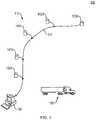
Fig. 1 is a schematic diagram of an environment in which a GNSS jammer, whose location is initially unknown, is present along with a system for determining the location of the jammer in accordance with the invention;Fig. 2 is a block diagram of a representative one of the augmented GNSS receivers shown inFig. 1 ;Figs. 3A and3B are a flowchart illustrating a method for determining the location of a GNSS jammer in conjunction with the system ofFig. 1 ;Fig. 4 illustrates a method of using early, punctual and late correlation data and a discriminator function to improve the accuracy of determining the location of a GNSS jammer; andFig. 5 graphically illustrates the computed hyperbolic curves used to determine the location of a GNSS jammer.Fig. 1 shows anenvironment 100 in which augmented GNSSreceivers 102a-102e are located at fixed, known locations that are separated by a minimum distance on the order of 100 meters. Augmented GNSSreceivers 102a-102e are substantially similar in construction, the details of which are described below in connection withFig. 2 . Augmented GNSSreceivers 102a-102e are connected by anetwork 104 to aserver 106.Network 104 may represent a local area network, either wired or wireless, which is capable of supporting the data transfers and other activities described herein. It should be understood that other communication links could be substituted for or used in conjunction withnetwork 104.Server 106 may be implemented as, for example, a commercially available personal computer (PC), notebook or other computing device which has sufficient CPU, memory, mass storage and other resources to perform the data processing operations described herein. Alternatively, multiple servers (not shown) may be used to distribute the data processing load and improve performance.- Augmented GNSS
receivers 102a-102e,network 104 andserver 106 together form asystem 110 for determining the location of an interfering signal source. An interferingsignal source 108, whose location is initially unknown, is present inenvironment 100 and is transmitting one or more signals which interfere with the normal operations of augmented GNSSreceivers 102a-102e. Interferingsignal source 108 may represent, for example, a truck driver operating a handheld GNSS jammer. Fig. 2 is a block diagram of augmentedGNSS receiver 102a which is representative ofreceivers 102a-102e. AGNSS antenna 200 is coupled to a digitalGNSS front end 202. A chip scaleatomic clock 204 is coupled tofront end 202 and functions as a highly accurate local clock for augmentedGNSS receiver 102a. Alternatively, a local clock could be based upon GNSS time, generated by a temperature compensated crystal oscillator, obtained from local signals of opportunity (e.g., broadcast AM or FM radio or television signals, or geo-stationary communications satellites) or transmitted overnetwork 104.- A local PC 206 is coupled to
front end 202 and a removablehard drive 208, and includes a network interface card (not shown) or other interface tonetwork 104.Front end 202 includes anRF section 210, a Multiple Independent Nomadic Stargazer (MINOS) andprocessor section 212, an analog to digital (A/D)sampling section 214, and adigital section 216. Alternatively, augmentedGNSS receiver 102a may be constructed without local PC 206 or removablehard drive 208 provided that sufficient random access memory (RAM) and appropriate network connectivity are provided, thereby enabling data samples collected byreceiver 102a to be stored and forwarded toserver 106. - GNSS
antenna 200 may be implemented with a GPS-702-GG GNSS antenna available from NovAtel Inc. of Calgary, Alberta. GNSSfront end 202 may be implemented with a Digital GNSS Front End (DGFE) also available from NovAtel Inc. Chip scaleatomic clock 204 may be implemented with a Symmetricom Chip Scale Atomic Clock. Local PC 206 and removablehard drive 208 may be implemented with an Intel® Atom™ based PC board with a 1 TB removable hard drive, respectively. MINOS andprocessor section 212 may be implemented with an OEMV1DF also available from NovAtel Inc. - In general, augmented
GNSS receiver 102a is capable of receiving signals in the GNSS bands including potentially interfering signals. Specifically, signals received byGNSS antenna 200, including L1 and L2, are passed toRF section 210 where they are filtered and downconverted to IF. The filtered and downconverted signals are then passed to A/D sampling section 214 which generates I/Q data samples at a rate preferably on the order of at least approximately 2.5 megasamples per second. Alternatively, higher sampling rates, up to at least approximately 20 to 30 megasamples per second, may be used provided that augmented GNSSreceiver 102a is adequately provisioned to either store locally or store and forward the collected samples. - At a sampling rate of 5 megasamples per second, the time between successive samples is 200 ns or a distance equivalent of approximately 60 meters, which is not sufficiently precise for most applications. However, as described in detail below in connection with
Fig. 4 , an interpolation technique based on a discriminator function may be used to improve accuracy to a few meters in the final position determination. - The data samples are time-tagged by
digital section 216 with the current time (e.g., the time indicated by chip scale atomic clock 204) ofaugmented GNSS receiver 102a. The time-tagged data samples may be stored bylocal PC 206 on removablehard drive 208 along with the phase and pseudorange for the GNSS satellites, and the position and clock offset information foraugmented GNSS receiver 102a. The time-tagged data samples and related information are subsequently packetized for transmission overnetwork 104 toserver 106. - The above-described process of receiving signals, generating time-tagged samples and forwarding those samples to
server 106 is carried out in parallel in each ofaugmented GNSS receivers 102a-102e (Fig. 1 ). Thus, in the event that an interfering signal appears and is within the bandwidth offront end 202, it is likely that multiple ones (if not all) ofaugmented GNSS receivers 102a-102e will receive the interfering signal, generate time-tagged samples associated with that signal and forward those samples toserver 106. So long as at least threeaugmented GNSS receivers 102a-102e received the interfering signal and generated time-tagged samples, there should be sufficient information available to determine the location of the interfering signal source. Figs. 3A and3B are a flowchart illustrating a method of determining the location of a GNSS jammer using the time-tagged samples generated byaugmented GNSS receivers 102a-102e described above. The method shown inFigs. 3A and3B may be implemented entirely onserver 106 or distributed across multiple servers.- The method begins at
step 302 with the collection of time-tagged RF samples from each ofaugmented GNSS receivers 102a-102e and conversion of those samples to the frequency domain by way of a fast Fourier transform (FFT) function. Next, atstep 304, the converted samples from a given one ofreceivers 102a-102e are analyzed in an effort to identify an interfering signal (or signals) having a power level above a threshold of interest. In general, an interfering signal would be expected to have a power level significantly higher than those of GNSS signals of interest. Further, if more than one interfering signal is present, each such signal will likely have at least one characteristic which will permit unique identification. For example, an interfering signal may have a unique frequency signature, power spike, signal transients, harmonics, angle of arrival at a givenaugmented GNSS receiver 102a-102e, or other characteristics. - Assuming that at least one interfering signal is identified at
step 304, the method then continues to step 306 where converted samples associated with the interfering signal are located among the samples originating from at least two otheraugmented GNSS receivers 102a-102e, thereby creating a total of at least three data sets associated with the interfering signal. - Next, at
step 308, for each of the at least three data sets associated with the interfering signal, all non-signal related FFT spectral frequencies are set to zero and the data sets are converted back to the time domain using an inverse FFT function. Atstep 310, by using the clock offset information previously received fromaugmented GNSS receivers 102a-102e as well as the time-tags,server 106 is able to perform a cross-correlation function with an initial pair of the (time domain) data sets which represent simultaneous observations by twoaugmented GNSS receivers 102a-102e. Throughstep 312, this processing is continued iteratively until all unique pairs of data sets have been cross-correlated. - At
step 314, the cross-correlation for each pair of data sets is examined for the peak correlation value. As described in detail below in connection withFig. 4 , using the peak correlation value along with correlation values just prior to (early) and just after (late) the peak value, a discriminator function is used to compute a time difference of arrival (TDOA) with respect to each pair of data sets (corresponding to a pair ofaugmented GNSS receivers 102a-102e). The computed TDOA represents the difference in time between when the interfering signal arrived at the two augmented GNSS receivers associated with the data sets. The discriminator function advantageously serves to significantly improve the accuracy of the computed TDOA and, in turn, the accuracy of the location determination of the GNSS jammer. - If the ratio of a correlation's peak value over the average correlation is above a specified tolerance, the computed TDOA may be corrected for the difference in each augmented GNSS receiver's clock offset.
- Once a TDOA is computed for each unique pair of data sets, the method continues to step 316 at which hyperbolic curves are computed for each TDOA according to the following equation:

- where (xi,yi) is the unknown location of the GNSS jammer
- (xA,yA) is the known location of augmented GNSS receiver A
- (xB,yB) is the known location of augmented GNSS receiver B
- TDOAiAB is the time difference of arrival of the interfering signal at augmented GNSS receiver A and augmented GNSS receiver B
- C is the speed of light
- Results of the jammer location determination are reported or displayed (or both) at
step 318. For example, inFig. 5 , results of the computation of the hyperbolic curves are plotted to illustrate the location of a GNSS jammer. The jammer's location is determined to be the intersection of two curves corresponding to TDOAAB (representing the TDOA between augmented GNSS receivers A and B), TDOABC (representing the TDOA between augmented GNSS receivers B and C) and TDOAAC (representing the TDOA between augmented GNSS receivers A and C). - The method of least squares is typically used to solve for the unknown location of a GNSS jammer (xi,yi) using a linearization of the TDOA equations for each combination of augmented GNSS receivers (AB, BC, AC). If the TDOAs computed using more than three augmented GNSS receivers are used in the least squares computation, the root mean squared of the residuals may be computed and compared against a tolerance to determine if the computed position is acceptable. Thus, the overall process of determining the location of a GNSS jammer (xi,yi) may be summarized as follows:
- 1. Solve for the TDOA using cross correlation and a discriminator function.
- 2. The TDOA equation is a hyperbolic line equation that can be written with TDOA as a function of the known augmented GNSS receiver coordinates and the unknown GNSS jammer coordinates. In least squares terms: l=f(x), where l = observations(TDOA) and x are the unknowns (GNSS jammer coordinates).
- 3. Linearize the TDOA function using Ax+w = 1, where A is the design matrix formed by A = df/dx ... derivative of TDOA equation with respect to the unknowns and w is the misclosure matrix (TDOA - TDOA'), where TDOA' is computed using approximate coordinates (x0) for the GNSS jammer.
- 4. Using the least squares process solve for the corrections to x by:

- where C1 is the covariance matrix of the observations.
- x=x0+Δ, where x0 are the approximate coordinates of the GNSS jammer.
- 5. Since the TDOA equation is non-linear, iterate steps 3 and 4. After updating x in step 4, reform A and w with the new approximate coordinates and then solve for Δ again, continuing until Δ (the corrections to the unknowns) falls below a certain tolerance (e.g., 1 mm).
Fig. 4 shows acorrelation peak 400 resulting from the cross-correlation function performed instep 310 ofFig. 3A . Because an interfering signal from a GNSS jammer is wideband and resembles a pulse or chirp, the cross-correlation of data samples from different augmented GNSS receivers relating to such a signal will produce a symmetrical correlation peak similar topeak 400. That is, the expected actual correlation peak for the interfering signal will be at the apex of a symmetrical triangle containing the early, punctual and late correlation points (corresponding to the correlator values on three consecutive samples). It should be understood that if more than one interfering signal is present the correlation peak may not be symmetrical or two peaks may be present.- As shown
Fig. 4 , (Xe,Ye) represents the early correlation point, (Xp,Yp) represents a punctual correlation point, and (XL,YL) represents a late correlation point. The actual correlation peak is represented by (Xc,Yc). Tos represents a time offset between the punctual and actual peak correlation points. Ts represents the time interval between successive samples. At a sampling rate of 5 megasamples per second, Ts = 1/5 MHz = 200 ns. Given the correlation values of Ye, Yp and YL along with Ts, the actual correlation peak may be solved for as follows. - For the case where Ye is less than YL, the value of Tos may be computed using the equation:

- For the case where Ye is greater than YL, the value of Tos may be computed using the equation:

- Through the use of the discriminator function described above, accuracy in the determination of a jammer's location may be improved from on the order of +/- 60 meters to +/- 3 meters.
- If a jammer or other source of an interfering signal is moving, there will be an apparent Doppler shift of its frequency observed by
augmented GNSS receivers 102a-102e (Fig. 1 ) The magnitude of the Doppler shift will depend upon the relative speed of the interfering signal source with respect to the location of each receiver. For example, if the interfering signal source is moving towards a particular receiver, there would be a corresponding positive Doppler shift and the apparent frequency of the interfering signal would increase. Conversely, if the interfering signal source is moving away from a particular receiver, there would be a negative Doppler shift and the apparent frequency would decrease. Assuming thataugmented GNSS receivers 102a-102e are located randomly withinenvironment 100, a relative direction of travel with respect to each such receiver would be different from the other receivers, thereby producing unique Doppler shifts observable at each receiver. Absent knowledge of the exact frequency of an interfering signal, Doppler differences between neighboring receivers could be used to determine a location of the interfering signal source.


Claims (14)
- A system for determining a location of an interfering signal source (108), the system comprising:a server (106) connected in communicating relationship to at least three augmented GNSS receivers (102a-102e), each of said augmented GNSS receivers (102a-102e) located at a known location;each of said augmented GNSS receivers (102a-102e) including a GNSS antenna, a digital GNSS front end, a local clock, and a processor;each augmented GNSS receiver (102a-102e) configured to sample GNSS signals and at least one interfering signal from a source, time-tag each sample with a time of receipt produced by the local clock, and transmit each time-tagged sample to said server (106); andsaid server (106) configured to identify time-tagged samples associated with said at least one interfering signal within time-tagged samples received from each augmented GNSS receiver (102a-102e), and for reach unique pair of augmented GNSS receivers (102a-102e)cross-correlate the identified time-tagged samples for each unique pair of the at least three augmented GNSS receivers (102a-102e) to produce a correlation result for each unique pair of the at least three augmented GNSS receivers (102a-102e),apply a discriminator function to each correlation result to compute a time difference of arrival for each unique pair of the at least three augmented GNSS receivers (102a-102e), where the time difference of arrival is computed utilizing a punctual correlation value from the correlation result, an early correlation value from the correlation result that is prior to the punctual correlation value, and a late correlation value from the correlation result that is later than the punctual correlation value; anddetermine a location of the source (108) of said interfering signal utilizing the time difference of arrival computed for each unique pair of the at least three augmented GNSS receivers (102a-102e).
- The system of claim 1 wherein each of said augmented GNSS receivers (102a-102e) samples said GNSS signals and said at least one interfering signal at a rate of at least approximately 2.5 megasamples per second.
- The system of claim 1 or 2 wherein said local clock comprises a chip scale atomic clock.
- The system of any one of claims 1 to 3 wherein said server (106) is further configured to convert said time-tagged samples using a fast Fourier transform function (FFT).
- The system of claim 4 wherein said server (106) is further configured to identify a first data set including converted samples originating from one of said augmented GNSS receivers (102a-102e) and associated with said at least one interfering signal by comparing a power level of one or more said converted samples to a threshold.
- The system of claim 5 wherein said server (106) is further configured 1 to identify a total of at least three data sets each of which includes converted samples originating from one of at least three of said augmented GNSS receivers (102a-102e) and associated with said at least one interfering signal, particularly wherein said server (106) is further configured, with respect to each of said at least three data sets, to set to zero all non-signal related FFT spectral frequencies and convert to using an inverse FFT function.
- The system of any one of claims 1 to 6 wherein said server (106) is further configured to compute an apparent Doppler shift in time-tagged samples received from each augmented GNSS receiver and associated with said at least one interfering signal, particularly wherein said server (106) is further configured to compute differences in apparent Doppler shifts with respect to neighboring augmented GNSS receivers (102a-102e) and to use such differences to compute a location of a source (106) of said interfering signal.
- A method for determining a location of an interfering signal source (108), the system comprising:at each of at least three augmented GNSS receivers (102a-102e) located at known locations, collecting samples of GNSS signals and at least one interfering signal;time-tagging each of said samples with a time of receipt;identifying time-tagged samples associated with said at least one interfering signal, from a source, within time-tagged samples received from each augmented GNSS receiver (102a-102e);cross-correlating the identified time-tagged samples for each unique pair of the at least three augmented GNSS receivers (102a-102e) to produce a correlation result for each unique pair of the at least three augmented GNSS receivers (102a-102e);applying a discriminator function to each correlation result to compute a time difference of arrival for each unique pair of the at least three augmented GNSS receivers (102a-102e), where the time difference of arrival is computed utilizing a punctual correlation value from the correlation result, an early correlation value of the correlation result that is prior to the punctual correlation value, and a late correlation value of the correlation result that is later than the punctual correlation value; anddetermine a location of the source (108) of said interfering signal utilizing the time difference of arrival computed for each unique pair of the at least three augmented GNSS receivers (102a-102e).
- The method of claim 8 wherein each of said augmented GNSS receivers (102a-102e) samples said GNSS signals and said at least one interfering signal at a rate of at least approximately 2.5 megasamples per second.
- The method of claim 8 or 9 wherein said time of receipt is generated by a chip scale atomic clock.
- The method of any one of claims 8 to 10 wherein said time-1 tagged samples are converted to a frequency domain using a fast Fourier transform function (FFT).
- The method of claim 11 wherein a first data set, including converted samples associated with said at least one interfering signal, is identified from converted samples originating from one of said augmented GNSS receivers (102a-102e) by comparing a power level of one or more said converted samples to a threshold.
- The method of claim 12 wherein a total of at least three data sets each of which includes converted samples associated with said at least one interfering signal and originating from one of said at least three augmented GNSS receivers (102a-102e).
- The method of claim 13 wherein, with respect to each of said at least three data sets, all non-signal related FFT spectral frequencies are set to zero and said data sets converted to a time domain using an inverse FFT function.
Applications Claiming Priority (1)
| Application Number | Priority Date | Filing Date | Title |
|---|---|---|---|
| US14/309,104US9766343B2 (en) | 2014-06-19 | 2014-06-19 | System and method for determining location of an interfering signal source |
Publications (2)
| Publication Number | Publication Date |
|---|---|
| EP2957927A1 EP2957927A1 (en) | 2015-12-23 |
| EP2957927B1true EP2957927B1 (en) | 2021-04-21 |
Family
ID=53541498
Family Applications (1)
| Application Number | Title | Priority Date | Filing Date |
|---|---|---|---|
| EP15172301.2AActiveEP2957927B1 (en) | 2014-06-19 | 2015-06-16 | System and method for determining location of an interfering signal source |
Country Status (3)
| Country | Link |
|---|---|
| US (1) | US9766343B2 (en) |
| EP (1) | EP2957927B1 (en) |
| CA (1) | CA2893723C (en) |
Families Citing this family (8)
| Publication number | Priority date | Publication date | Assignee | Title |
|---|---|---|---|---|
| IL239103B (en)* | 2015-05-31 | 2020-08-31 | Ben Moshe Boaz | Navigation system interference locator |
| US10284326B2 (en)* | 2017-05-10 | 2019-05-07 | Talen-X, Inc. | Penalty-based environment monitoring |
| US11269078B1 (en)* | 2019-01-30 | 2022-03-08 | Architecture Technology Corporation | Systems and methods for detecting global positioning system spoofing signal emitters |
| CN110068839B (en)* | 2019-03-15 | 2023-04-28 | 中国人民解放军63601部队 | Satellite navigation receiver interference detection method based on data statistics characteristics |
| US11277203B1 (en) | 2020-01-22 | 2022-03-15 | Architecture Technology Corporation | Hybrid communications based upon aerial networks |
| CN116736343A (en)* | 2023-06-15 | 2023-09-12 | 云南电网有限责任公司怒江供电局 | Optimal weight coefficient improved GNSS anti-interference method based on multi-antenna array |
| US12140684B1 (en)* | 2023-12-15 | 2024-11-12 | Hubble Network Inc. | Location determination using angle-of-arrival and time-of-flight |
| CN119483783B (en)* | 2024-11-21 | 2025-09-26 | 北京理工大学 | A channel knowledge graph construction method for non-cooperative interference sources |
Family Cites Families (18)
| Publication number | Priority date | Publication date | Assignee | Title |
|---|---|---|---|---|
| US5008679A (en)* | 1990-01-31 | 1991-04-16 | Interferometrics Incorporated | Method and system for locating an unknown transmitter |
| BR9510640A (en) | 1995-09-20 | 1999-03-16 | Secr Defence | Method and apparatus for locating the source of an unknown signal received from several signal relays |
| US5936571A (en) | 1997-01-31 | 1999-08-10 | Lockheed Martin Corporation | Integrated GPS/interference location system |
| WO2001065271A1 (en) | 1998-10-09 | 2001-09-07 | Cell-Loc Inc. | Methods and apparatus to position a mobile receiver using downlink signals |
| US6512803B2 (en)* | 2000-04-05 | 2003-01-28 | Symmetricom, Inc. | Global positioning system receiver capable of functioning in the presence of interference |
| US7512492B2 (en) | 2001-04-13 | 2009-03-31 | General Dynamics Advanced Information Systems, Inc. | System and method for detecting interference in global positioning satellite signals |
| US6882310B1 (en)* | 2003-10-15 | 2005-04-19 | Raytheon Company | Direct sampling GPS receiver for anti-interference operations |
| KR100617787B1 (en)* | 2004-06-29 | 2006-08-28 | 삼성전자주식회사 | Global Positioning System Receiver and Method for Detecting Jammer Using Fast Fourier Transform |
| CN101855566B (en) | 2007-11-13 | 2014-06-04 | 诺瓦特公司 | System and method for determining position over a network |
| CA2724994C (en) | 2008-05-22 | 2014-08-12 | Novatel Inc. | Gnss receiver using signals of opportunity and assistance information to reduce the time to first fix |
| US8446310B2 (en) | 2008-08-22 | 2013-05-21 | Raytheon Company | Method and system for locating signal jammers |
| US8138975B2 (en) | 2008-12-30 | 2012-03-20 | Trueposition, Inc. | Interference detection, characterization and location in a wireless communications or broadcast system |
| EP2585846B1 (en)* | 2010-06-25 | 2016-08-03 | Innovationszentrum für Telekommunikationstechnik GmbH IZT | Method and system for determining a time difference, method and system for finding a position of a transmitter |
| US8344947B2 (en)* | 2010-09-14 | 2013-01-01 | Cellguide Ltd. | Multipath mitigation in positioning systems |
| WO2012112113A1 (en)* | 2011-02-18 | 2012-08-23 | Telefonaktiebolaget L M Ericsson (Publ) | Method and arrangement for positioning a wireless device |
| KR101221978B1 (en)* | 2012-09-03 | 2013-01-15 | 한국항공우주연구원 | Localization method of multiple jammers based on tdoa method |
| KR101240629B1 (en)* | 2012-11-30 | 2013-03-11 | 한국항공우주연구원 | Detecting and localization method of unknown signal using aircraft with ads-b system |
| US9651652B2 (en)* | 2013-02-07 | 2017-05-16 | L3 Technologies, Inc. | Interference cancellation system for location and direction finding |
- 2014
- 2014-06-19USUS14/309,104patent/US9766343B2/enactiveActive
- 2015
- 2015-06-03CACA2893723Apatent/CA2893723C/enactiveActive
- 2015-06-16EPEP15172301.2Apatent/EP2957927B1/enactiveActive
Non-Patent Citations (1)
| Title |
|---|
| None* |
Also Published As
| Publication number | Publication date |
|---|---|
| CA2893723C (en) | 2020-10-06 |
| US20150369922A1 (en) | 2015-12-24 |
| US9766343B2 (en) | 2017-09-19 |
| CA2893723A1 (en) | 2015-12-19 |
| EP2957927A1 (en) | 2015-12-23 |
Similar Documents
| Publication | Publication Date | Title |
|---|---|---|
| EP2957927B1 (en) | System and method for determining location of an interfering signal source | |
| US9829560B2 (en) | Determining the position of a mobile device using the characteristics of received signals and a reference database | |
| US9173187B2 (en) | Determining the position of a mobile device using the characteristics of received signals and a reference database | |
| KR102132152B1 (en) | Method and system of timing and localizing a radio signal | |
| EP2294439B1 (en) | Measurement of time of arrival | |
| Pegoraro et al. | JUMP: Joint communication and sensing with unsynchronized transceivers made practical | |
| US8199047B2 (en) | High-precision radio frequency ranging system | |
| EP4100759B1 (en) | Resilient distributed positioning networks | |
| US20120139789A1 (en) | Transmitter independent techniques to extend the performance of passive coherent location | |
| CN108089205B (en) | A UAV flight control personnel positioning system | |
| US9910132B2 (en) | Systems and methods for coherent signal fusion for time and frequency estimation | |
| US12235340B2 (en) | Distance measurement device and distance measurement method | |
| US6646602B2 (en) | Technique for robust characterization of weak RF emitters and accurate time difference of arrival estimation for passive ranging of RF emitters | |
| EP3399334A1 (en) | Object detecting device and sensor device | |
| Cyganski et al. | A multi-carrier technique for precision geolocation for indoor/multipath environments | |
| EP2642311B1 (en) | Method and apparatus for improving measurement precision in the area of travelling time differences of signals | |
| JP2015036628A (en) | Passive radar device | |
| CA2741844C (en) | System for positioning a geostationary satellite | |
| JP2005195347A (en) | Direction sensor and radio wave emission source position estimation system | |
| JP6311198B2 (en) | White space detection device, white space detection method, and program | |
| Irsyad et al. | Reliability Study of TDoA-based Emission Localization in Using Simple RTL-SDRs | |
| CN116634557A (en) | Train positioning method, device and system in tunnel based on multi-slot distinction | |
| Alabd et al. | Analysis of interference effects on CaCS-based radar systems | |
| RU162946U1 (en) | PASSIVE COAGER LOCATOR | |
| Pfister | Localization with vehicular WLAN based on null frame round trip time measurement |
Legal Events
| Date | Code | Title | Description |
|---|---|---|---|
| PUAI | Public reference made under article 153(3) epc to a published international application that has entered the european phase | Free format text:ORIGINAL CODE: 0009012 | |
| AK | Designated contracting states | Kind code of ref document:A1 Designated state(s):AL AT BE BG CH CY CZ DE DK EE ES FI FR GB GR HR HU IE IS IT LI LT LU LV MC MK MT NL NO PL PT RO RS SE SI SK SM TR | |
| AX | Request for extension of the european patent | Extension state:BA ME | |
| 17P | Request for examination filed | Effective date:20160819 | |
| RBV | Designated contracting states (corrected) | Designated state(s):AL AT BE BG CH CY CZ DE DK EE ES FI FR GB GR HR HU IE IS IT LI LT LU LV MC MK MT NL NO PL PT RO RS SE SI SK SM TR | |
| STAA | Information on the status of an ep patent application or granted ep patent | Free format text:STATUS: EXAMINATION IS IN PROGRESS | |
| 17Q | First examination report despatched | Effective date:20181004 | |
| GRAP | Despatch of communication of intention to grant a patent | Free format text:ORIGINAL CODE: EPIDOSNIGR1 | |
| STAA | Information on the status of an ep patent application or granted ep patent | Free format text:STATUS: GRANT OF PATENT IS INTENDED | |
| INTG | Intention to grant announced | Effective date:20201125 | |
| RAP1 | Party data changed (applicant data changed or rights of an application transferred) | Owner name:NOVATEL INC. | |
| GRAS | Grant fee paid | Free format text:ORIGINAL CODE: EPIDOSNIGR3 | |
| GRAA | (expected) grant | Free format text:ORIGINAL CODE: 0009210 | |
| STAA | Information on the status of an ep patent application or granted ep patent | Free format text:STATUS: THE PATENT HAS BEEN GRANTED | |
| AK | Designated contracting states | Kind code of ref document:B1 Designated state(s):AL AT BE BG CH CY CZ DE DK EE ES FI FR GB GR HR HU IE IS IT LI LT LU LV MC MK MT NL NO PL PT RO RS SE SI SK SM TR | |
| REG | Reference to a national code | Ref country code:GB Ref legal event code:FG4D | |
| REG | Reference to a national code | Ref country code:CH Ref legal event code:EP | |
| REG | Reference to a national code | Ref country code:DE Ref legal event code:R096 Ref document number:602015068292 Country of ref document:DE Ref country code:IE Ref legal event code:FG4D | |
| REG | Reference to a national code | Ref country code:CH Ref legal event code:NV Representative=s name:KAMINSKI HARMANN PATENTANWAELTE AG, LI | |
| REG | Reference to a national code | Ref country code:AT Ref legal event code:REF Ref document number:1385214 Country of ref document:AT Kind code of ref document:T Effective date:20210515 | |
| REG | Reference to a national code | Ref country code:LT Ref legal event code:MG9D | |
| REG | Reference to a national code | Ref country code:AT Ref legal event code:MK05 Ref document number:1385214 Country of ref document:AT Kind code of ref document:T Effective date:20210421 | |
| REG | Reference to a national code | Ref country code:NL Ref legal event code:MP Effective date:20210421 | |
| PG25 | Lapsed in a contracting state [announced via postgrant information from national office to epo] | Ref country code:LT Free format text:LAPSE BECAUSE OF FAILURE TO SUBMIT A TRANSLATION OF THE DESCRIPTION OR TO PAY THE FEE WITHIN THE PRESCRIBED TIME-LIMIT Effective date:20210421 Ref country code:NL Free format text:LAPSE BECAUSE OF FAILURE TO SUBMIT A TRANSLATION OF THE DESCRIPTION OR TO PAY THE FEE WITHIN THE PRESCRIBED TIME-LIMIT Effective date:20210421 Ref country code:FI Free format text:LAPSE BECAUSE OF FAILURE TO SUBMIT A TRANSLATION OF THE DESCRIPTION OR TO PAY THE FEE WITHIN THE PRESCRIBED TIME-LIMIT Effective date:20210421 Ref country code:BG Free format text:LAPSE BECAUSE OF FAILURE TO SUBMIT A TRANSLATION OF THE DESCRIPTION OR TO PAY THE FEE WITHIN THE PRESCRIBED TIME-LIMIT Effective date:20210721 Ref country code:AT Free format text:LAPSE BECAUSE OF FAILURE TO SUBMIT A TRANSLATION OF THE DESCRIPTION OR TO PAY THE FEE WITHIN THE PRESCRIBED TIME-LIMIT Effective date:20210421 Ref country code:HR Free format text:LAPSE BECAUSE OF FAILURE TO SUBMIT A TRANSLATION OF THE DESCRIPTION OR TO PAY THE FEE WITHIN THE PRESCRIBED TIME-LIMIT Effective date:20210421 | |
| PG25 | Lapsed in a contracting state [announced via postgrant information from national office to epo] | Ref country code:ES Free format text:LAPSE BECAUSE OF FAILURE TO SUBMIT A TRANSLATION OF THE DESCRIPTION OR TO PAY THE FEE WITHIN THE PRESCRIBED TIME-LIMIT Effective date:20210421 Ref country code:PL Free format text:LAPSE BECAUSE OF FAILURE TO SUBMIT A TRANSLATION OF THE DESCRIPTION OR TO PAY THE FEE WITHIN THE PRESCRIBED TIME-LIMIT Effective date:20210421 Ref country code:NO Free format text:LAPSE BECAUSE OF FAILURE TO SUBMIT A TRANSLATION OF THE DESCRIPTION OR TO PAY THE FEE WITHIN THE PRESCRIBED TIME-LIMIT Effective date:20210721 Ref country code:PT Free format text:LAPSE BECAUSE OF FAILURE TO SUBMIT A TRANSLATION OF THE DESCRIPTION OR TO PAY THE FEE WITHIN THE PRESCRIBED TIME-LIMIT Effective date:20210823 Ref country code:RS Free format text:LAPSE BECAUSE OF FAILURE TO SUBMIT A TRANSLATION OF THE DESCRIPTION OR TO PAY THE FEE WITHIN THE PRESCRIBED TIME-LIMIT Effective date:20210421 Ref country code:SE Free format text:LAPSE BECAUSE OF FAILURE TO SUBMIT A TRANSLATION OF THE DESCRIPTION OR TO PAY THE FEE WITHIN THE PRESCRIBED TIME-LIMIT Effective date:20210421 Ref country code:IS Free format text:LAPSE BECAUSE OF FAILURE TO SUBMIT A TRANSLATION OF THE DESCRIPTION OR TO PAY THE FEE WITHIN THE PRESCRIBED TIME-LIMIT Effective date:20210821 Ref country code:GR Free format text:LAPSE BECAUSE OF FAILURE TO SUBMIT A TRANSLATION OF THE DESCRIPTION OR TO PAY THE FEE WITHIN THE PRESCRIBED TIME-LIMIT Effective date:20210722 Ref country code:LV Free format text:LAPSE BECAUSE OF FAILURE TO SUBMIT A TRANSLATION OF THE DESCRIPTION OR TO PAY THE FEE WITHIN THE PRESCRIBED TIME-LIMIT Effective date:20210421 | |
| REG | Reference to a national code | Ref country code:DE Ref legal event code:R097 Ref document number:602015068292 Country of ref document:DE | |
| PG25 | Lapsed in a contracting state [announced via postgrant information from national office to epo] | Ref country code:CZ Free format text:LAPSE BECAUSE OF FAILURE TO SUBMIT A TRANSLATION OF THE DESCRIPTION OR TO PAY THE FEE WITHIN THE PRESCRIBED TIME-LIMIT Effective date:20210421 Ref country code:EE Free format text:LAPSE BECAUSE OF FAILURE TO SUBMIT A TRANSLATION OF THE DESCRIPTION OR TO PAY THE FEE WITHIN THE PRESCRIBED TIME-LIMIT Effective date:20210421 Ref country code:DK Free format text:LAPSE BECAUSE OF FAILURE TO SUBMIT A TRANSLATION OF THE DESCRIPTION OR TO PAY THE FEE WITHIN THE PRESCRIBED TIME-LIMIT Effective date:20210421 Ref country code:SK Free format text:LAPSE BECAUSE OF FAILURE TO SUBMIT A TRANSLATION OF THE DESCRIPTION OR TO PAY THE FEE WITHIN THE PRESCRIBED TIME-LIMIT Effective date:20210421 Ref country code:SM Free format text:LAPSE BECAUSE OF FAILURE TO SUBMIT A TRANSLATION OF THE DESCRIPTION OR TO PAY THE FEE WITHIN THE PRESCRIBED TIME-LIMIT Effective date:20210421 Ref country code:MC Free format text:LAPSE BECAUSE OF FAILURE TO SUBMIT A TRANSLATION OF THE DESCRIPTION OR TO PAY THE FEE WITHIN THE PRESCRIBED TIME-LIMIT Effective date:20210421 Ref country code:RO Free format text:LAPSE BECAUSE OF FAILURE TO SUBMIT A TRANSLATION OF THE DESCRIPTION OR TO PAY THE FEE WITHIN THE PRESCRIBED TIME-LIMIT Effective date:20210421 | |
| PLBE | No opposition filed within time limit | Free format text:ORIGINAL CODE: 0009261 | |
| STAA | Information on the status of an ep patent application or granted ep patent | Free format text:STATUS: NO OPPOSITION FILED WITHIN TIME LIMIT | |
| REG | Reference to a national code | Ref country code:BE Ref legal event code:MM Effective date:20210630 | |
| 26N | No opposition filed | Effective date:20220124 | |
| PG25 | Lapsed in a contracting state [announced via postgrant information from national office to epo] | Ref country code:LU Free format text:LAPSE BECAUSE OF NON-PAYMENT OF DUE FEES Effective date:20210616 | |
| PG25 | Lapsed in a contracting state [announced via postgrant information from national office to epo] | Ref country code:IE Free format text:LAPSE BECAUSE OF NON-PAYMENT OF DUE FEES Effective date:20210616 | |
| PG25 | Lapsed in a contracting state [announced via postgrant information from national office to epo] | Ref country code:IS Free format text:LAPSE BECAUSE OF FAILURE TO SUBMIT A TRANSLATION OF THE DESCRIPTION OR TO PAY THE FEE WITHIN THE PRESCRIBED TIME-LIMIT Effective date:20210821 Ref country code:AL Free format text:LAPSE BECAUSE OF FAILURE TO SUBMIT A TRANSLATION OF THE DESCRIPTION OR TO PAY THE FEE WITHIN THE PRESCRIBED TIME-LIMIT Effective date:20210421 | |
| PG25 | Lapsed in a contracting state [announced via postgrant information from national office to epo] | Ref country code:IT Free format text:LAPSE BECAUSE OF FAILURE TO SUBMIT A TRANSLATION OF THE DESCRIPTION OR TO PAY THE FEE WITHIN THE PRESCRIBED TIME-LIMIT Effective date:20210421 Ref country code:BE Free format text:LAPSE BECAUSE OF NON-PAYMENT OF DUE FEES Effective date:20210630 | |
| PG25 | Lapsed in a contracting state [announced via postgrant information from national office to epo] | Ref country code:HU Free format text:LAPSE BECAUSE OF FAILURE TO SUBMIT A TRANSLATION OF THE DESCRIPTION OR TO PAY THE FEE WITHIN THE PRESCRIBED TIME-LIMIT; INVALID AB INITIO Effective date:20150616 | |
| PG25 | Lapsed in a contracting state [announced via postgrant information from national office to epo] | Ref country code:CY Free format text:LAPSE BECAUSE OF FAILURE TO SUBMIT A TRANSLATION OF THE DESCRIPTION OR TO PAY THE FEE WITHIN THE PRESCRIBED TIME-LIMIT Effective date:20210421 | |
| PG25 | Lapsed in a contracting state [announced via postgrant information from national office to epo] | Ref country code:MK Free format text:LAPSE BECAUSE OF FAILURE TO SUBMIT A TRANSLATION OF THE DESCRIPTION OR TO PAY THE FEE WITHIN THE PRESCRIBED TIME-LIMIT Effective date:20210421 | |
| PG25 | Lapsed in a contracting state [announced via postgrant information from national office to epo] | Ref country code:MT Free format text:LAPSE BECAUSE OF FAILURE TO SUBMIT A TRANSLATION OF THE DESCRIPTION OR TO PAY THE FEE WITHIN THE PRESCRIBED TIME-LIMIT Effective date:20210421 | |
| PGFP | Annual fee paid to national office [announced via postgrant information from national office to epo] | Ref country code:CH Payment date:20240704 Year of fee payment:10 | |
| PGFP | Annual fee paid to national office [announced via postgrant information from national office to epo] | Ref country code:DE Payment date:20250627 Year of fee payment:11 | |
| PGFP | Annual fee paid to national office [announced via postgrant information from national office to epo] | Ref country code:GB Payment date:20250627 Year of fee payment:11 | |
| PGFP | Annual fee paid to national office [announced via postgrant information from national office to epo] | Ref country code:FR Payment date:20250625 Year of fee payment:11 |