EP2957101B1 - Solid-state imaging device, driving method thereof, and imaging apparatus - Google Patents
Solid-state imaging device, driving method thereof, and imaging apparatusDownload PDFInfo
- Publication number
- EP2957101B1 EP2957101B1EP14704403.6AEP14704403AEP2957101B1EP 2957101 B1EP2957101 B1EP 2957101B1EP 14704403 AEP14704403 AEP 14704403AEP 2957101 B1EP2957101 B1EP 2957101B1
- Authority
- EP
- European Patent Office
- Prior art keywords
- pixel block
- pixel
- solid
- imaging device
- pixels
- Prior art date
- Legal status (The legal status is an assumption and is not a legal conclusion. Google has not performed a legal analysis and makes no representation as to the accuracy of the status listed.)
- Active
Links
Images


Classifications
- H—ELECTRICITY
- H04—ELECTRIC COMMUNICATION TECHNIQUE
- H04N—PICTORIAL COMMUNICATION, e.g. TELEVISION
- H04N25/00—Circuitry of solid-state image sensors [SSIS]; Control thereof
- H04N25/40—Extracting pixel data from image sensors by controlling scanning circuits, e.g. by modifying the number of pixels sampled or to be sampled
- H—ELECTRICITY
- H04—ELECTRIC COMMUNICATION TECHNIQUE
- H04N—PICTORIAL COMMUNICATION, e.g. TELEVISION
- H04N25/00—Circuitry of solid-state image sensors [SSIS]; Control thereof
- H04N25/70—SSIS architectures; Circuits associated therewith
- H04N25/76—Addressed sensors, e.g. MOS or CMOS sensors
- H04N25/78—Readout circuits for addressed sensors, e.g. output amplifiers or A/D converters
Definitions
- the present disclosurerelates to a solid-state imaging element, a driving method thereof, and an imaging apparatus, and in particular, to a solid-state imaging element which is preferable when providing an Analog-Digital (AD) conversion unit in each pixel block configured by a plurality of pixels, a driving method thereof, and an imaging apparatus.
- ADAnalog-Digital
- CMOS image sensorAs a solid-state imaging device which is mounted on a digital still camera, or a digital video camera, a CMOS image sensor (hereinafter, abbreviated to CIS) has been known.
- CISCMOS image sensor
- the CISis used in an imaging apparatus for sensing, and in a case of such a use, rapidity of operations is particularly necessary.
- ADCAD conversion unit
- optical characteristics of pixelsare sacrificed when providing the ADC in the same substrate of the pixel.
- pixels and ADCsare provided on separate substrates, and both of the substrates are connected by being bonded using Cu-Cu bonding in order not to sacrifice optical characteristics of the pixels.
- a size of one ADCusually corresponds to a size of a plurality of pixels, the plurality of pixels on the separate substrate are correspondingly connected to the one ADC (for example, refer to PTL 1).
- Fig. 1illustrates a conceptual diagram when a pixel block which is configured by 16 pixels of 4 ⁇ 4 pixels in total is correspondingly connected to one ADC on a separate substrate.
- a rectangle of a thin linedenotes a pixel
- a thick linedenotes a pixel block which is correlated with one ADC
- numbersdenote positions of pixels
- arrowsdenote scanning order of pixels.
- a pixel which is located on an X row and a Y columnis described as a pixel (X, Y).
- scanningis started in the right horizontal direction by setting a pixel on the lower left (3,0) as a starting point, and a row to be scanned is moved in the upper vertical direction sequentially, and an upper right pixel (0,3) is lastly read out.
- scanningis started in the right horizontal direction by setting a pixel on the lower left (3,4) as a starting point, and a row to be scanned is moved in the upper vertical direction sequentially, and an upper right pixel (0,7) is lastly read out.
- a pixel on the lower leftis set to a starting point, scanning is started in the right horizontal direction, a row to be scanned is moved in the upper vertical direction sequentially, and a pixel on the upper right is lastly read out.
- a solid-state imaging devicewhich has a pixel unit with a plurality of pixels arranged in a two-dimensional shape.
- US 2006/0013485 A1discloses a solid-state imaging device, wherein an AD converter is mounted on the same chip.
- a CCD image sensing devicehaving a plurality of pixel areas.
- scanning timings(timings of being read out) of pixels on a boundary between neighboring pixel blocks, for example, a pixel (0, 3) and a pixel (0,4), a pixel (3,3) and a pixel (3,4), a pixel (3,0) and a pixel (4,0), and the like, do not match with each other.
- deviation in scanning timingis merely by 16 pixels at the most, however, a correction becomes difficult when accumulating time of pixels is short, or when there is a motion of an object. Accordingly, blurring occurs in an image on a boundary between pixel blocks, and when the CIS is used for image sensing, or the like, a recognition rate in recognition of a moving body is lowered.
- the present disclosurehas been made in consideration of such a situation, and has been made so that blurring docs not occur in an image on a boundary between pixel blocks, when one ADC is correlated with a pixel block which is configured by a plurality of pixels, in a CIS.
- the present inventionprovides a solid-state imaging device in accordance with independent claim 1.
- the present inventionprovides a method for driving a solid-state imaging device in accordance with independent claim 7.
- the present inventionprovides an imaging apparatus in accordance with claim 13. Further aspects of the invention are set forth in the dependent claims, the drawings and the following description.
- Fig. 2is a conceptual diagram which illustrates that a solid-state imaging device as embodiments of the present disclosure is configured by two substrates. That is, the solid-state imaging device 10 is configured by an upper substrate 11 and a lower substrate 12, and the upper substrate 11 and lower substrate 12 are bonded using Cu-Cu bonding, or the like, and are connected to each other at corresponding portions.
- Figs. 3A and 3Bschematically illustrate the upper substrate 11 and the lower substrate 12, and respective circuit configurations thereof.
- the upper substrate 11is provided with a plurality of pixels 21 which are arranged in a matrix, a vertical scanning unit 23, and a horizontal scanning unit 24.
- Each of the plurality of pixels 21is divided into one pixel block 22 by 4 ⁇ 4 pixels.
- the pixel 21generates a charge corresponding to input light using photoelectric conversion processing, accumulates the charge, and transmits a pixel signal corresponding to the accumulated charge to an ADC 31 of the lower substrate 12 at a scanning timing based on a control from the vertical scanning unit 23 and the horizontal scanning unit 24.
- the pixel block 22is configured by 16 pixels of 4 ⁇ 4 pixels in total, however, the number of pixels 21, or a shape thereof which configures the pixel block 22 is arbitrary, and is not limited to 4 ⁇ 4 pixels.
- the lower substrate 12is provided with a plurality of ADCs 31 which respectively correspond to the pixel block 22 of the upper substrate 11, a digital signal processing unit 32, a timing generation unit 33, and a DAC 34.
- Each ADC 31converts analog pixel signals which are sequentially transmitted from the plurality of pixels 21 which belong to corresponding pixel block 22 into a digital signal.
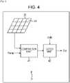
- Fig. 4illustrates a configuration example of the ADC 31.
- the ADC 31includes a comparison unit 41 and a latch unit 42.
- the comparison unit 41compares analog pixel signals which are sequentially transmitted from each pixel 21 of a corresponding pixel block 22 with a Ramp signal which is input from the DAC 34, and outputs a comparison result thereof to the latch unit 42.
- the latch unit 42maintains an input code value when a Ramp signal crosses the pixel signal based on the comparison result of the comparison unit 41.
- the code value which is maintained in the latch unit 42is read out in the digital signal processing unit 32 as a digital pixel signal.
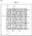
- Fig. 5illustrates an example of scanning order of the plurality of pixels 21 in each pixel block 22 which is provided on the upper substrate 11 of the solid-state imaging device 10.
- a rectangle of a thin linedenotes a pixel 21
- a thick linedenotes a pixel block 22 which is correlated with one ADC 31
- numbersdenote positions of pixels
- arrowsdenote scanning order of pixels.
- a pixel 21 of an X row and a Y columnis described as a pixel (X,Y).
- a pixel (0,0)is located on the upper left top
- scanningis started in the right horizontal direction by setting a lower left pixel (3,0) as a starting point
- a row to be scannedis moved in the upper vertical direction sequentially
- a pixel on the upper right (0,3)is lastly scanned.
- a pixel block 22 0,4in which a pixel (0,4) is located on the upper left top, scanning is started in the left horizontal direction by setting a lower right pixel (3,7) as a starting point, a row to be scanned is moved in the upper vertical direction sequentially, and a pixel on the upper left (0,4) is lastly scanned.
- a pixel block 22 0,8in which a pixel (0,8) is located on the upper left top, scanning is started in the right horizontal direction by setting a lower left pixel (3,8) as a starting point, a row to be scanned is moved in the upper vertical direction sequentially, and a pixel on the upper right (0,11) is lastly scanned.
- a pixel block 22 4,0in which a pixel (4,0) is located on the upper left top, scanning is started in the right horizontal direction by setting the upper left pixel (4,0) as a starting point, a row to be scanned is moved in the upper vertical direction sequentially, and a pixel on the lower right (7,3) is lastly scanned.
- a pixel block 22 4,4in which a pixel (4,4) is located on the upper left top, scanning is started in the left horizontal direction by setting the upper right pixel (4,7) as a starting point, a row to be scanned is moved in the lower vertical direction sequentially, and a pixel on the lower left (7,4) is lastly scanned.
- a pixel block 22 4,8in which a pixel (4,8) is located on the upper left top, scanning is started in the right horizontal direction by setting the upper left pixel (4,8) as a starting point, a row to be scanned is moved in the lower vertical direction sequentially, and a pixel on the lower right (7,11) is lastly scanned.
- a pixel block 22 8,0in which a pixel (8,0) is located on the upper left top, scanning is started in the right horizontal direction by setting the lower left pixel (11,0) as a starting point, a row to be scanned is moved in the upper vertical direction sequentially, and a pixel on the upper right (8,3) is lastly scanned.
- a pixel block 22 8,4in which a pixel (8,4) is located on the upper left top, scanning is started in the left horizontal direction by setting the lower right pixel (11,7) as a starting point, a row to be scanned is moved in the upper vertical direction sequentially, and a pixel on the upper left (8,4) is lastly scanned.
- a pixel block 22 8,8in which a pixel (8,8) is located on the upper left top, scanning is started in the right horizontal direction by setting the lower left pixel (11,8) as a starting point, a row to be scanned is moved in the upper vertical direction sequentially, and a pixel on the upper right (8,11) is lastly scanned.
- pixel blocks 22 of which scanning order is common to that of the pixel block 22 X,Yare a pixel block 22 X, Y+8 which is separated by one pixel block in the right direction, a pixel block 22 X, Y-8 which is separated by one pixel block in the left direction, a pixel block 22 X-8, Y which is separated by one pixel block in the upper direction, and a pixel block 22 X+8, Y which is separated by one pixel block in the lower direction.
- scanning order of a pixel block 22 X,Y+4 , and a pixel block 22 X, Y-4 which are close to the pixel block 22 X,Y on the left and right with respect to the scanning order of the pixel block 22 X,Yis opposite in a movement in the horizontal direction, and is common in a movement in the vertical direction.
- scanning order of a pixel block 22 X-4, Y , and a pixel block 22 X+4, Y which are vertically close to the pixel block 22 X,Y with respect to the scanning order of the pixel block 22 X,Yis opposite in a movement in the vertical direction, and is common in a movement in the horizontal direction.
- scanning order of a pixel block 22 X-4, Y-4 , a pixel block 22 X-4, Y+4 , a pixel block 22 X+4, Y-4 , and a pixel block 22 X+4, Y+4which are located diagonally to the pixel block 22 X,Y with respect to the scanning order of the pixel block 22 X,Y is opposite in a movement in the horizontal direction, and is also opposite in a movement in the vertical direction.
- Scanning timings of pixels which are located on a boundary of neighboring pixel blocks 22typically match with each other when setting scanning order of the 16 pixels which belong to each pixel block 22 as illustrated in the figure. Accordingly, it is possible to prevent blurring in an image from occurring on a boundary of pixel blocks 22, and to suppress a change in topology of an object in an image.
- the solid-state imaging device 10is preferable for a use of sensing in particular, and can suppress lowering of a recognition rate when recognizing a moving body.
- Fig. 6illustrates another example of scanning order of the plurality of pixels 21 in each pixel block 22 which is provided on the upper substrate 11 of the solid-state imaging device 10.
- a rectangle of a thin linedenotes a pixel 21
- a thick linedenotes a pixel block 22 which is correlated with one ADC 31
- numbersdenote positions of pixels
- arrowsdenote scanning order of pixels.
- scanning order of 16 pixels which belong to a pixel block 22is moved in the horizontal direction by setting any one of the four vertices of the pixel block 22 as the starting point, and is spirally moved up to a center of the pixel block 22 thereafter.
- pixel blocks 22 of which scanning order is common to that of the pixel block 22 X,Yare a pixel block 22 X, Y+8 which is separated by one pixel block in the right direction, a pixel block 22 X, Y-8 which is separated by one pixel block in the left direction, a pixel block 22 X-8, Y which is separated by one pixel block in the upper direction, and a pixel block 22 X+8, Y which is separated by one pixel block in the lower direction.
- the starting point of the scanning order of the pixel block 22 X,Yis the upper left among the four vertices
- the starting points of the scanning order of a pixel block 22 X,Y+4 , and a pixel block 22 X, Y-4 which are close to the pixel block 22 X,Y on the left and rightbecome the upper right among the four vertices.
- starting points of the scanning order of a pixel block 22 X-4,Y , and a pixel block 22 X+4, Y which are vertically close to the pixel block 22 X,Ybecome the lower left among the four vertices.
- the starting point of the scanning order of the pixel block 22 X-4, Y-4 , the pixel block 22 X-4, Y+4 , the pixel block 22 X+4, Y-4 , and the pixel block 22 X+4, Y+4 , which are located diagonally to the pixel block 22 X,Ybecomes the lower right among the four vertices.
- scanning order of the plurality of pixels 21 in each pixel block 22 which is provided on the upper substrate 11 of the solid-state imaging device 10is not limited to the example which is illustrated in Fig. 5 or 6 , and scanning order of pixels on a boundary between neighboring pixel blocks may be set so as to match typically.
- Fig. 7illustrates a configuration example of an imaging apparatus 50 on which the solid-state imaging device 10 is mounted.
- the solid-state imaging device 10performs photoelectric conversion processing according to input light which is condensed by an optical lens 51, and outputs a digital image signal based on a charge which is generated as a result thereof to a DSP 52.
- the imaging apparatus 50can be used for sensing, for example.
Landscapes
- Engineering & Computer Science (AREA)
- Multimedia (AREA)
- Signal Processing (AREA)
- Transforming Light Signals Into Electric Signals (AREA)
- Solid State Image Pick-Up Elements (AREA)
Description
- The present disclosure relates to a solid-state imaging element, a driving method thereof, and an imaging apparatus, and in particular, to a solid-state imaging element which is preferable when providing an Analog-Digital (AD) conversion unit in each pixel block configured by a plurality of pixels, a driving method thereof, and an imaging apparatus.
- As a solid-state imaging device which is mounted on a digital still camera, or a digital video camera, a CMOS image sensor (hereinafter, abbreviated to CIS) has been known. In addition, there is a case in which the CIS is used in an imaging apparatus for sensing, and in a case of such a use, rapidity of operations is particularly necessary.
- For acceleration of operations of the CIS, a method in which an AD conversion unit (hereinafter, abbreviated to ADC) is provided to one, or a relatively small number of pixels, and a plurality of the ADCs are operated in parallel has been known.
- In such a method, optical characteristics of pixels are sacrificed when providing the ADC in the same substrate of the pixel.
- Therefore, a configuration in which pixels and ADCs are provided on separate substrates, and both of the substrates are connected by being bonded using Cu-Cu bonding in order not to sacrifice optical characteristics of the pixels has been proposed. In addition, since a size of one ADC usually corresponds to a size of a plurality of pixels, the plurality of pixels on the separate substrate are correspondingly connected to the one ADC (for example, refer to PTL 1).
Fig. 1 illustrates a conceptual diagram when a pixel block which is configured by 16 pixels of 4∗4 pixels in total is correspondingly connected to one ADC on a separate substrate. In the figure, a rectangle of a thin line denotes a pixel, a thick line denotes a pixel block which is correlated with one ADC, numbers denote positions of pixels, and arrows denote scanning order of pixels. In addition, a pixel which is located on an X row and a Y column is described as a pixel (X, Y).- For example, in a pixel block of which a pixel (0,0) is on the upper left top, scanning is started in the right horizontal direction by setting a pixel on the lower left (3,0) as a starting point, and a row to be scanned is moved in the upper vertical direction sequentially, and an upper right pixel (0,3) is lastly read out. Similarly, in a right neighbor pixel block of the pixel block, scanning is started in the right horizontal direction by setting a pixel on the lower left (3,4) as a starting point, and a row to be scanned is moved in the upper vertical direction sequentially, and an upper right pixel (0,7) is lastly read out.
- That is, in each pixel block, a pixel on the lower left is set to a starting point, scanning is started in the right horizontal direction, a row to be scanned is moved in the upper vertical direction sequentially, and a pixel on the upper right is lastly read out.
- From
US 2012/0120293 A1 a solid-state imaging device is known, which has a pixel unit with a plurality of pixels arranged in a two-dimensional shape. - From
US 2009/0091806 A1 a solid-state imaging device is known, in which a plurality of photoelectric conversion elements are divided into a plurality of photoelectric conversion element groups. US 2006/0013485 A1 discloses a solid-state imaging device, wherein an AD converter is mounted on the same chip.- From
US 20013/0130562 A1 - From
US 2003/0025820 A1 , a CCD image sensing device is known, having a plurality of pixel areas. - From
US 2009/0242950 A1 , a vertically-integrated image sensor is known. - PTL 1:
Japanese Unexamined Patent Application Publication No. 2009-177207 - In a case of a scanning order which is illustrated in
Fig. 1 , scanning timings (timings of being read out) of pixels on a boundary between neighboring pixel blocks, for example, a pixel (0, 3) and a pixel (0,4), a pixel (3,3) and a pixel (3,4), a pixel (3,0) and a pixel (4,0), and the like, do not match with each other. In addition, in a case of a pixel block of 4∗4 pixels, deviation in scanning timing is merely by 16 pixels at the most, however, a correction becomes difficult when accumulating time of pixels is short, or when there is a motion of an object. Accordingly, blurring occurs in an image on a boundary between pixel blocks, and when the CIS is used for image sensing, or the like, a recognition rate in recognition of a moving body is lowered. - The present disclosure has been made in consideration of such a situation, and has been made so that blurring docs not occur in an image on a boundary between pixel blocks, when one ADC is correlated with a pixel block which is configured by a plurality of pixels, in a CIS.
- According to a first aspect, the present invention provides a solid-state imaging device in accordance with
independent claim 1. According to a second aspect, the present invention provides a method for driving a solid-state imaging device in accordance withindependent claim 7. According to a third aspect, the present invention provides an imaging apparatus in accordance with claim 13. Further aspects of the invention are set forth in the dependent claims, the drawings and the following description. - According to the embodiments, it is possible to suppress occurring of blurring of an image on a boundary between pixel blocks.
- [
fig.1] Fig. 1 is a diagram which illustrates scanning order of a pixel in a pixel block in the related art. - [
fig.2]Fig. 2 is a diagram which illustrates a configuration example of a substrate of a solid-state imaging device to which the present disclosure is applied. - [
fig.3A]Fig. 3A is a block diagram which illustrates configuration example of an upper substrate inFig. 2 . - [
fig.3B]Fig. 3B is a block diagram which illustrates configuration example of a lower substrate inFig. 2 . - [
fig.4]Fig. 4 is a block diagram which illustrates a configuration example of an ADC. - [
fig.5]Fig. 5 is a diagram which illustrates scanning order of pixels in pixel blocks according to the present disclosure. - [
fig.6]Fig. 6 is a diagram which illustrates scanning order of pixels in pixel blocks according to the present disclosure. - [
fig.7]Fig. 7 is a block diagram which illustrates a configuration example of an imaging apparatus according to the present disclosure. - Hereinafter, best forms for executing the present disclosure (hereinafter, referred to as embodiments) will be described in detail with reference to drawings.
Fig. 2 is a conceptual diagram which illustrates that a solid-state imaging device as embodiments of the present disclosure is configured by two substrates. That is, the solid-state imaging device 10 is configured by anupper substrate 11 and alower substrate 12, and theupper substrate 11 andlower substrate 12 are bonded using Cu-Cu bonding, or the like, and are connected to each other at corresponding portions.Figs. 3A and 3B schematically illustrate theupper substrate 11 and thelower substrate 12, and respective circuit configurations thereof.- As illustrated in
Fig. 3A , theupper substrate 11 is provided with a plurality ofpixels 21 which are arranged in a matrix, avertical scanning unit 23, and ahorizontal scanning unit 24. Each of the plurality ofpixels 21 is divided into onepixel block 22 by 4∗4 pixels. Thepixel 21 generates a charge corresponding to input light using photoelectric conversion processing, accumulates the charge, and transmits a pixel signal corresponding to the accumulated charge to anADC 31 of thelower substrate 12 at a scanning timing based on a control from thevertical scanning unit 23 and thehorizontal scanning unit 24. - In addition, according to the embodiment, the
pixel block 22 is configured by 16 pixels of 4∗4 pixels in total, however, the number ofpixels 21, or a shape thereof which configures thepixel block 22 is arbitrary, and is not limited to 4∗4 pixels. - As illustrated in
Fig. 3B , thelower substrate 12 is provided with a plurality ofADCs 31 which respectively correspond to thepixel block 22 of theupper substrate 11, a digital signal processing unit 32, atiming generation unit 33, and aDAC 34. EachADC 31 converts analog pixel signals which are sequentially transmitted from the plurality ofpixels 21 which belong tocorresponding pixel block 22 into a digital signal. Fig. 4 illustrates a configuration example of theADC 31. The ADC 31 includes acomparison unit 41 and alatch unit 42. Thecomparison unit 41 compares analog pixel signals which are sequentially transmitted from eachpixel 21 of acorresponding pixel block 22 with a Ramp signal which is input from theDAC 34, and outputs a comparison result thereof to thelatch unit 42. Thelatch unit 42 maintains an input code value when a Ramp signal crosses the pixel signal based on the comparison result of thecomparison unit 41. The code value which is maintained in thelatch unit 42 is read out in the digital signal processing unit 32 as a digital pixel signal.Fig. 5 illustrates an example of scanning order of the plurality ofpixels 21 in eachpixel block 22 which is provided on theupper substrate 11 of the solid-state imaging device 10. In the figure, a rectangle of a thin line denotes apixel 21, a thick line denotes apixel block 22 which is correlated with oneADC 31, numbers denote positions of pixels, and arrows denote scanning order of pixels. In addition, apixel 21 of an X row and a Y column is described as a pixel (X,Y).- For example, in a
pixel block 220,0 in which a pixel (0,0) is located on the upper left top, scanning is started in the right horizontal direction by setting a lower left pixel (3,0) as a starting point, a row to be scanned is moved in the upper vertical direction sequentially, and a pixel on the upper right (0,3) is lastly scanned. - In a
pixel block 220,4 in which a pixel (0,4) is located on the upper left top, scanning is started in the left horizontal direction by setting a lower right pixel (3,7) as a starting point, a row to be scanned is moved in the upper vertical direction sequentially, and a pixel on the upper left (0,4) is lastly scanned. - In a
pixel block 220,8 in which a pixel (0,8) is located on the upper left top, scanning is started in the right horizontal direction by setting a lower left pixel (3,8) as a starting point, a row to be scanned is moved in the upper vertical direction sequentially, and a pixel on the upper right (0,11) is lastly scanned. - In a
pixel block 224,0 in which a pixel (4,0) is located on the upper left top, scanning is started in the right horizontal direction by setting the upper left pixel (4,0) as a starting point, a row to be scanned is moved in the upper vertical direction sequentially, and a pixel on the lower right (7,3) is lastly scanned. - In a
pixel block 224,4 in which a pixel (4,4) is located on the upper left top, scanning is started in the left horizontal direction by setting the upper right pixel (4,7) as a starting point, a row to be scanned is moved in the lower vertical direction sequentially, and a pixel on the lower left (7,4) is lastly scanned. - In a
pixel block 224,8 in which a pixel (4,8) is located on the upper left top, scanning is started in the right horizontal direction by setting the upper left pixel (4,8) as a starting point, a row to be scanned is moved in the lower vertical direction sequentially, and a pixel on the lower right (7,11) is lastly scanned. - In a
pixel block 228,0 in which a pixel (8,0) is located on the upper left top, scanning is started in the right horizontal direction by setting the lower left pixel (11,0) as a starting point, a row to be scanned is moved in the upper vertical direction sequentially, and a pixel on the upper right (8,3) is lastly scanned. - In a
pixel block 228,4 in which a pixel (8,4) is located on the upper left top, scanning is started in the left horizontal direction by setting the lower right pixel (11,7) as a starting point, a row to be scanned is moved in the upper vertical direction sequentially, and a pixel on the upper left (8,4) is lastly scanned. - In a
pixel block 228,8 in which a pixel (8,8) is located on the upper left top, scanning is started in the right horizontal direction by setting the lower left pixel (11,8) as a starting point, a row to be scanned is moved in the upper vertical direction sequentially, and a pixel on the upper right (8,11) is lastly scanned. - That is, there are four patterns of scanning order of the 16 pixels which belong to the
pixel block 22, and when paying attention to apixel block 22X,Y, pixel blocks 22 of which scanning order is common to that of thepixel block 22X,Y are apixel block 22X, Y+8 which is separated by one pixel block in the right direction, apixel block 22X, Y-8 which is separated by one pixel block in the left direction, apixel block 22X-8, Y which is separated by one pixel block in the upper direction, and apixel block 22X+8, Y which is separated by one pixel block in the lower direction. - In addition, scanning order of a
pixel block 22X,Y+4, and apixel block 22X, Y-4 which are close to thepixel block 22X,Y on the left and right with respect to the scanning order of thepixel block 22X,Y is opposite in a movement in the horizontal direction, and is common in a movement in the vertical direction. - In addition, scanning order of a
pixel block 22X-4, Y, and apixel block 22X+4, Y which are vertically close to thepixel block 22X,Y with respect to the scanning order of thepixel block 22X,Y is opposite in a movement in the vertical direction, and is common in a movement in the horizontal direction. - In addition, scanning order of a
pixel block 22X-4, Y-4, apixel block 22X-4, Y+4, apixel block 22X+4, Y-4, and apixel block 22X+4, Y+4, which are located diagonally to thepixel block 22X,Y with respect to the scanning order of thepixel block 22X,Y is opposite in a movement in the horizontal direction, and is also opposite in a movement in the vertical direction. - Scanning timings of pixels which are located on a boundary of neighboring pixel blocks 22 typically match with each other when setting scanning order of the 16 pixels which belong to each
pixel block 22 as illustrated in the figure. Accordingly, it is possible to prevent blurring in an image from occurring on a boundary of pixel blocks 22, and to suppress a change in topology of an object in an image. - In this case, when there is a motion in an object, a direction of a distortion of an image in each
pixel block 22 becomes different, however, in a case of a use for sensing, in many cases, the change in topology influences recognizing of a moving body rather than the difference in the direction of the distortion in each pixel block. Accordingly, the solid-state imaging device 10 according to the embodiment is preferable for a use of sensing in particular, and can suppress lowering of a recognition rate when recognizing a moving body. Fig. 6 illustrates another example of scanning order of the plurality ofpixels 21 in eachpixel block 22 which is provided on theupper substrate 11 of the solid-state imaging device 10. In the figure, as well, a rectangle of a thin line denotes apixel 21, a thick line denotes apixel block 22 which is correlated with oneADC 31, numbers denote positions of pixels, and arrows denote scanning order of pixels.- In a case of the figure, scanning order of 16 pixels which belong to a
pixel block 22 is moved in the horizontal direction by setting any one of the four vertices of thepixel block 22 as the starting point, and is spirally moved up to a center of thepixel block 22 thereafter. - Even in a case of the figure, when there are four patterns of scanning order of the 16 pixels which belong to a
pixel block 22, and paying attention to apixel block 22X,Y, pixel blocks 22 of which scanning order is common to that of thepixel block 22X,Y are apixel block 22X, Y+8 which is separated by one pixel block in the right direction, apixel block 22X, Y-8 which is separated by one pixel block in the left direction, apixel block 22X-8, Y which is separated by one pixel block in the upper direction, and apixel block 22X+8, Y which is separated by one pixel block in the lower direction. - When the starting point of the scanning order of the
pixel block 22X,Y is the upper left among the four vertices, the starting points of the scanning order of apixel block 22X,Y+4, and apixel block 22X, Y-4 which are close to thepixel block 22X,Y on the left and right become the upper right among the four vertices. - In addition, starting points of the scanning order of a
pixel block 22X-4,Y, and apixel block 22X+4, Y which are vertically close to thepixel block 22X,Y become the lower left among the four vertices. - In addition, the starting point of the scanning order of the
pixel block 22X-4, Y-4, thepixel block 22X-4, Y+4, thepixel block 22X+4, Y-4, and thepixel block 22X+4, Y+4, which are located diagonally to thepixel block 22X,Y becomes the lower right among the four vertices. - In the case of
Fig. 6 , as well, similarly to the case inFig. 5 , scanning timings of pixels which are located on the boundary between neighboring pixel blocks 22 typically match with each other. Accordingly, it is possible to prevent blurring in an image from occurring on a boundary between pixel blocks 22, and to suppress a change in topology of an object in an image. - In addition, scanning order of the plurality of
pixels 21 in eachpixel block 22 which is provided on theupper substrate 11 of the solid-state imaging device 10 is not limited to the example which is illustrated inFig. 5 or6 , and scanning order of pixels on a boundary between neighboring pixel blocks may be set so as to match typically. Fig. 7 illustrates a configuration example of animaging apparatus 50 on which the solid-state imaging device 10 is mounted. In theimaging apparatus 50, the solid-state imaging device 10 performs photoelectric conversion processing according to input light which is condensed by anoptical lens 51, and outputs a digital image signal based on a charge which is generated as a result thereof to aDSP 52. Theimaging apparatus 50 can be used for sensing, for example.- In addition, the embodiment of the present disclosure is not limited to the above described embodiments, and can be variously modified without departing from the scope of the present invention as defined by the appended claims.
- 10 SOLID-STATE IMAGING DEVICE
- 11 UPPER SUBSTRATE
- 12 LOWER SUBSTRATE
- 21 PIXEL
- 22 PIXEL BLOCK
- 31 ADC
- 50 IMAGING APPARATUS
Claims (13)
- A solid-state imaging device comprising:a CMOS imaging sensor, includinga plurality of pixel blocks (22) arranged in a matrix, respective ones of the pixel blocks (22) including a plurality of pixels (21) configured to generate a charge corresponding to input light, wherein respective ones of the pixels (21) within a respective pixel block (22) are arranged in a square submatrix, anda plurality of analog-to-digital converters (31), respective ones of the analog-to-digital converters (31) disposed corresponding to respective ones of the pixel blocks; the solid-state imaging device further comprisinga control unit including a vertical scanning unit (23) and a horizontal scanning unit (24); whereinthe control unit is configured to scan the pixels (21) of each pixel block (22) according to a scanning sequence associated with the respective pixel block (22), the scanning sequence being set so as to sequentially scan the pixels (21) of the respective pixel block (22) at a timing such that adjacent pixels (21) of adjacent pixel blocks (22) which are located on a boundary of the adjacent pixel blocks (22) are scanned simultaneously.
- The solid-state imaging device according to claim 1, wherein
the control unit is configured to sequentially scan respective ones of the pixels (21) such that the scanning sequence of a respective pixel block (22) is reversed in either the row direction or the column direction with respect to a scanning sequence of an adjacent pixel block (22). - The solid-state imaging device according to claim 1 or 2, wherein
the control unit is configured to sequentially scan respective ones of the pixels (21) such that the scanning sequence of a respective pixel block (22) is reversed in either the row direction or the column direction with respect to a scanning sequence of all directly adjacent pixel blocks (22). - The solid-state imaging device according to any one of claims 1 to 3, wherein
the scanning sequence of the respective pixel block (22) is a pattern wherein scanning is started in a horizontal direction by setting a pixel (21) located at a corner of the respective pixel block (22) as a starting point, a row to be scanned is moved in the vertical direction sequentially, and a pixel (21) located at an opposite corner of the respective pixel block (22) is lastly scanned. - The solid-state imaging device according to any one of claims 1 to 3, wherein
the scanning sequence of the respective pixel block (22) is a rectilinear spiral pattern beginning with a pixel (21) located at a corner of the respective pixel block (22). - The solid-state imaging device according to any one of claims 1 to 5, further comprisingan upper substrate (11) including the plurality of pixel blocks (22) and the control unit; anda lower substrate (12) including the plurality of analog-to-digital converters (31) and a timing generation unit (33),wherein the upper substrate (11) and the lower substrate (12) are bonded and connected to each other at corresponding portions.
- A method of driving a solid-state imaging device (10) comprising a CMOS image sensor including a plurality of pixel blocks (22) arranged in a matrix, respective ones of the pixel blocks (22) including a plurality of pixels (21) configured to generate a charge corresponding to input light, wherein respective ones of the pixels (21) within a respective pixel block (22) are arranged in a square submatrix; and a plurality of analog-to-digital converters (31), respective ones of the analog-to-digital converters (31) disposed corresponding to respective ones of the pixel blocks (22), wherein the solid-state imaging device further comprises a control unit including a vertical scanning unit (23) and a horizontal scanning unit (24); and the method comprising the step of:
scanning the pixels (21) of each pixel block (22) according to a scanning sequence associated with the respective pixel block (22), the scanning sequence being set so as to sequentially scan the pixels (21) at a timing such that adjacent pixels (21) of adjacent pixel blocks (22) which are located on a boundary of the adjacent pixel blocks (22) are scanned simultaneously. - The method of driving a solid-state imaging device (10) according to claim 7, further comprising the step of:
sequentially scanning respective ones of the pixels (21) such that the scanning sequence of a respective pixel block (22) is reversed in either the row direction or the column direction with respect to a scanning sequence of an adjacent pixel block (22). - The method of driving a solid-state imaging device (10) according to claim 7 or 8, further comprising the step of:
sequentially scanning respective ones of the pixels (21) such that the scanning sequence of a respective pixel block (22) is reversed in either the row direction or the column direction with respect to a scanning sequence of all directly adjacent pixel blocks (22). - The method of driving a solid-state imaging device (10) according to any one of claims 7 to 9, wherein
the scanning sequence of the respective pixel block (22) is a pattern wherein scanning is started in a horizontal direction by setting a pixel (21) located at a corner of the respective pixel block (22) as a starting point, a row to be scanned is moved in the vertical direction sequentially, and a pixel (21) located at an opposite corner of the respective pixel block (22) is lastly scanned. - The method of driving a solid-state imaging device (10) according to any one of claims 7 to 9, wherein
the scanning sequence of the respective pixel block (22) is a rectilinear spiral pattern beginning with a pixel located at a corner of the respective pixel block (22). - The method of driving a solid-state imaging device according to any one of claims 7 to 11, further comprisingan upper substrate (11) including the plurality of pixel blocks and the control unit; anda lower substrate (12) including the plurality of analog-to-digital converters (31) and a timing generation unit (32),wherein the upper substrate (11) and the lower substrate (12) are bonded and connected to each other at corresponding portions.
- An imaging apparatus comprising:the solid-state imaging device (10) according to any one of claims 1 to 6;an optical lens (51) configured to condense light onto the solid-state imaging device (10); anda digital signal processor (52) configured to process an output signal of the solid-state imaging device (10).
Applications Claiming Priority (2)
| Application Number | Priority Date | Filing Date | Title |
|---|---|---|---|
| JP2013025831AJP5962533B2 (en) | 2013-02-13 | 2013-02-13 | Solid-state imaging device, driving method, and imaging apparatus |
| PCT/JP2014/000555WO2014125785A1 (en) | 2013-02-13 | 2014-02-03 | Solid-state imaging device, driving method thereof, and imaging apparatus |
Publications (2)
| Publication Number | Publication Date |
|---|---|
| EP2957101A1 EP2957101A1 (en) | 2015-12-23 |
| EP2957101B1true EP2957101B1 (en) | 2022-07-13 |
Family
ID=50102153
Family Applications (1)
| Application Number | Title | Priority Date | Filing Date |
|---|---|---|---|
| EP14704403.6AActiveEP2957101B1 (en) | 2013-02-13 | 2014-02-03 | Solid-state imaging device, driving method thereof, and imaging apparatus |
Country Status (7)
| Country | Link |
|---|---|
| US (2) | US9674472B2 (en) |
| EP (1) | EP2957101B1 (en) |
| JP (1) | JP5962533B2 (en) |
| KR (1) | KR102171962B1 (en) |
| CN (1) | CN104937923B (en) |
| TW (1) | TWI623231B (en) |
| WO (1) | WO2014125785A1 (en) |
Families Citing this family (6)
| Publication number | Priority date | Publication date | Assignee | Title |
|---|---|---|---|---|
| AU2016264606B2 (en)* | 2015-05-19 | 2020-09-03 | Magic Leap, Inc. | Semi-global shutter imager |
| JP6795030B2 (en) | 2016-04-27 | 2020-12-02 | ソニー株式会社 | Imaging control device, imaging control method, and imaging device |
| CN109076178B (en)* | 2016-05-11 | 2021-07-13 | 索尼公司 | Solid-state image pickup elements and electronic equipment |
| JP7023659B2 (en)* | 2017-09-29 | 2022-02-22 | キヤノン株式会社 | Imaging device, imaging system, mobile body |
| JP7316028B2 (en) | 2018-08-01 | 2023-07-27 | キヤノン株式会社 | IMAGE SENSOR, CONTROL METHOD THEREOF, AND IMAGING DEVICE |
| WO2021160843A2 (en)* | 2020-02-12 | 2021-08-19 | Samantree Medical Sa | Systems and methods for imaging samples with reduced sample motion artifacts |
Citations (3)
| Publication number | Priority date | Publication date | Assignee | Title |
|---|---|---|---|---|
| US20030025820A1 (en)* | 2001-08-02 | 2003-02-06 | Hiroyuki Miyahara | Method of transferring electric charge from image sensing device and image sensing device |
| KR20080100595A (en)* | 2007-05-14 | 2008-11-19 | 삼성전자주식회사 | Method and apparatus for processing images in mobile terminal |
| US20090242950A1 (en)* | 2008-03-31 | 2009-10-01 | Mccarten John P | Active pixel sensor having two wafers |
Family Cites Families (23)
| Publication number | Priority date | Publication date | Assignee | Title |
|---|---|---|---|---|
| JPH06259048A (en)* | 1993-03-09 | 1994-09-16 | Kuromatetsuku Kk | Screen dividing device |
| JP2000184282A (en)* | 1998-12-15 | 2000-06-30 | Canon Inc | Imaging device, driving method of imaging device, image processing method, information recording medium, and image processing system |
| JP2003032556A (en)* | 2001-07-16 | 2003-01-31 | Minolta Co Ltd | Imaging apparatus |
| US8423110B2 (en) | 2002-01-09 | 2013-04-16 | Boston Scientific Scimed, Inc. | Imaging device and related methods |
| JP4022862B2 (en)* | 2002-06-11 | 2007-12-19 | ソニー株式会社 | Solid-state imaging device and control method thereof |
| JP4468657B2 (en)* | 2003-04-28 | 2010-05-26 | オリンパス株式会社 | Image sensor |
| JP4075773B2 (en)* | 2003-11-05 | 2008-04-16 | ソニー株式会社 | Solid-state imaging device |
| JP4380439B2 (en)* | 2004-07-16 | 2009-12-09 | ソニー株式会社 | Data processing method, data processing apparatus, semiconductor device for detecting physical quantity distribution, and electronic apparatus |
| JP2006157862A (en) | 2004-11-08 | 2006-06-15 | Matsushita Electric Ind Co Ltd | MOS type image pickup device and image pickup apparatus |
| JP5106870B2 (en)* | 2006-06-14 | 2012-12-26 | 株式会社東芝 | Solid-state image sensor |
| KR100853094B1 (en)* | 2007-03-14 | 2008-08-19 | 동부일렉트로닉스 주식회사 | Image sensor and manufacturing method thereof |
| US7915702B2 (en)* | 2007-03-15 | 2011-03-29 | Eastman Kodak Company | Reduced pixel area image sensor |
| JP4350768B2 (en)* | 2007-04-16 | 2009-10-21 | キヤノン株式会社 | Photoelectric conversion device and imaging device |
| JP5172267B2 (en) | 2007-10-09 | 2013-03-27 | 富士フイルム株式会社 | Imaging device |
| JP5287111B2 (en)* | 2007-11-14 | 2013-09-11 | ソニー株式会社 | Display device, driving method thereof, and electronic apparatus |
| JP4478723B2 (en)* | 2008-03-31 | 2010-06-09 | キヤノン株式会社 | Solid-state imaging device and driving method of solid-state imaging device |
| JP5083272B2 (en)* | 2009-05-07 | 2012-11-28 | ソニー株式会社 | Semiconductor module |
| JP2011259407A (en)* | 2010-05-13 | 2011-12-22 | Sony Corp | Signal processing circuit, solid state image sensor, and camera system |
| JP5633323B2 (en) | 2010-11-11 | 2014-12-03 | ソニー株式会社 | Solid-state imaging device and electronic device |
| JP2012253624A (en)* | 2011-06-03 | 2012-12-20 | Sony Corp | Solid-state imaging device and camera system |
| TWI505453B (en)* | 2011-07-12 | 2015-10-21 | Sony Corp | Solid-state imaging device, method for driving the same, method for manufacturing the same, and electronic device |
| JP2013025831A (en) | 2011-07-15 | 2013-02-04 | Taiyo Yuden Co Ltd | Semiconductor memory device |
| US8890047B2 (en)* | 2011-09-21 | 2014-11-18 | Aptina Imaging Corporation | Stacked-chip imaging systems |
- 2013
- 2013-02-13JPJP2013025831Apatent/JP5962533B2/enactiveActive
- 2013-12-30TWTW102149130Apatent/TWI623231B/ennot_activeIP Right Cessation
- 2014
- 2014-02-03WOPCT/JP2014/000555patent/WO2014125785A1/enactiveApplication Filing
- 2014-02-03USUS14/765,203patent/US9674472B2/ennot_activeExpired - Fee Related
- 2014-02-03KRKR1020157020175Apatent/KR102171962B1/ennot_activeExpired - Fee Related
- 2014-02-03CNCN201480005811.9Apatent/CN104937923B/ennot_activeExpired - Fee Related
- 2014-02-03EPEP14704403.6Apatent/EP2957101B1/enactiveActive
- 2016
- 2016-12-02USUS15/368,213patent/US9800813B2/enactiveActive
Patent Citations (3)
| Publication number | Priority date | Publication date | Assignee | Title |
|---|---|---|---|---|
| US20030025820A1 (en)* | 2001-08-02 | 2003-02-06 | Hiroyuki Miyahara | Method of transferring electric charge from image sensing device and image sensing device |
| KR20080100595A (en)* | 2007-05-14 | 2008-11-19 | 삼성전자주식회사 | Method and apparatus for processing images in mobile terminal |
| US20090242950A1 (en)* | 2008-03-31 | 2009-10-01 | Mccarten John P | Active pixel sensor having two wafers |
Also Published As
| Publication number | Publication date |
|---|---|
| JP2014155175A (en) | 2014-08-25 |
| KR102171962B1 (en) | 2020-10-30 |
| CN104937923A (en) | 2015-09-23 |
| US20150381915A1 (en) | 2015-12-31 |
| TWI623231B (en) | 2018-05-01 |
| TW201433166A (en) | 2014-08-16 |
| JP5962533B2 (en) | 2016-08-03 |
| KR20150116827A (en) | 2015-10-16 |
| WO2014125785A1 (en) | 2014-08-21 |
| US9800813B2 (en) | 2017-10-24 |
| US20170085824A1 (en) | 2017-03-23 |
| EP2957101A1 (en) | 2015-12-23 |
| US9674472B2 (en) | 2017-06-06 |
| CN104937923B (en) | 2019-08-09 |
Similar Documents
| Publication | Publication Date | Title |
|---|---|---|
| US9800813B2 (en) | Solid-state imaging device, driving method thereof, and imaging apparatus | |
| US10694135B2 (en) | Solid-state imaging device and imaging apparatus | |
| US9420208B2 (en) | Driving method for image pickup apparatus and driving method for image pickup system | |
| US9674469B2 (en) | Solid-state imaging device, method of driving the same, and electronic apparatus | |
| CN109996016B (en) | Imaging device and electronic apparatus | |
| CN113824906B (en) | Image sensing device | |
| US20200221045A1 (en) | Imaging device and endoscope device | |
| US7826658B2 (en) | Image processing system, image processing method, image processing recording medium, and program suitable for extraction processing | |
| JP6137539B2 (en) | Solid-state imaging device, driving method thereof, and electronic apparatus | |
| US9143705B2 (en) | Signal providing apparatus, and analog-to-digital converting apparatus and image sensor using the same | |
| JP6173199B2 (en) | Image processing apparatus, image processing method, and imaging apparatus | |
| US20240378877A1 (en) | Imaging device, imaging method, and imaging program | |
| JP6257348B2 (en) | Solid-state imaging device, imaging system, and copying machine | |
| JP6173198B2 (en) | Image processing apparatus, image processing method, and imaging apparatus | |
| US12302012B2 (en) | Method of operating an image sensor | |
| CN113748670A (en) | Image pickup element and image pickup apparatus |
Legal Events
| Date | Code | Title | Description |
|---|---|---|---|
| PUAI | Public reference made under article 153(3) epc to a published international application that has entered the european phase | Free format text:ORIGINAL CODE: 0009012 | |
| 17P | Request for examination filed | Effective date:20150911 | |
| AK | Designated contracting states | Kind code of ref document:A1 Designated state(s):AL AT BE BG CH CY CZ DE DK EE ES FI FR GB GR HR HU IE IS IT LI LT LU LV MC MK MT NL NO PL PT RO RS SE SI SK SM TR | |
| AX | Request for extension of the european patent | Extension state:BA ME | |
| DAX | Request for extension of the european patent (deleted) | ||
| STAA | Information on the status of an ep patent application or granted ep patent | Free format text:STATUS: EXAMINATION IS IN PROGRESS | |
| 17Q | First examination report despatched | Effective date:20180829 | |
| RAP3 | Party data changed (applicant data changed or rights of an application transferred) | Owner name:SONY GROUP CORPORATION | |
| GRAP | Despatch of communication of intention to grant a patent | Free format text:ORIGINAL CODE: EPIDOSNIGR1 | |
| STAA | Information on the status of an ep patent application or granted ep patent | Free format text:STATUS: GRANT OF PATENT IS INTENDED | |
| INTG | Intention to grant announced | Effective date:20220204 | |
| GRAS | Grant fee paid | Free format text:ORIGINAL CODE: EPIDOSNIGR3 | |
| GRAA | (expected) grant | Free format text:ORIGINAL CODE: 0009210 | |
| STAA | Information on the status of an ep patent application or granted ep patent | Free format text:STATUS: THE PATENT HAS BEEN GRANTED | |
| AK | Designated contracting states | Kind code of ref document:B1 Designated state(s):AL AT BE BG CH CY CZ DE DK EE ES FI FR GB GR HR HU IE IS IT LI LT LU LV MC MK MT NL NO PL PT RO RS SE SI SK SM TR | |
| REG | Reference to a national code | Ref country code:GB Ref legal event code:FG4D | |
| REG | Reference to a national code | Ref country code:CH Ref legal event code:EP | |
| REG | Reference to a national code | Ref country code:IE Ref legal event code:FG4D | |
| REG | Reference to a national code | Ref country code:DE Ref legal event code:R096 Ref document number:602014084274 Country of ref document:DE | |
| REG | Reference to a national code | Ref country code:AT Ref legal event code:REF Ref document number:1504868 Country of ref document:AT Kind code of ref document:T Effective date:20220815 | |
| REG | Reference to a national code | Ref country code:LT Ref legal event code:MG9D | |
| REG | Reference to a national code | Ref country code:NL Ref legal event code:MP Effective date:20220713 | |
| REG | Reference to a national code | Ref country code:DE Ref legal event code:R079 Ref document number:602014084274 Country of ref document:DE Free format text:PREVIOUS MAIN CLASS: H04N0005341000 Ipc:H04N0025400000 | |
| PG25 | Lapsed in a contracting state [announced via postgrant information from national office to epo] | Ref country code:SE Free format text:LAPSE BECAUSE OF FAILURE TO SUBMIT A TRANSLATION OF THE DESCRIPTION OR TO PAY THE FEE WITHIN THE PRESCRIBED TIME-LIMIT Effective date:20220713 Ref country code:RS Free format text:LAPSE BECAUSE OF FAILURE TO SUBMIT A TRANSLATION OF THE DESCRIPTION OR TO PAY THE FEE WITHIN THE PRESCRIBED TIME-LIMIT Effective date:20220713 Ref country code:PT Free format text:LAPSE BECAUSE OF FAILURE TO SUBMIT A TRANSLATION OF THE DESCRIPTION OR TO PAY THE FEE WITHIN THE PRESCRIBED TIME-LIMIT Effective date:20221114 Ref country code:NO Free format text:LAPSE BECAUSE OF FAILURE TO SUBMIT A TRANSLATION OF THE DESCRIPTION OR TO PAY THE FEE WITHIN THE PRESCRIBED TIME-LIMIT Effective date:20221013 Ref country code:NL Free format text:LAPSE BECAUSE OF FAILURE TO SUBMIT A TRANSLATION OF THE DESCRIPTION OR TO PAY THE FEE WITHIN THE PRESCRIBED TIME-LIMIT Effective date:20220713 Ref country code:LV Free format text:LAPSE BECAUSE OF FAILURE TO SUBMIT A TRANSLATION OF THE DESCRIPTION OR TO PAY THE FEE WITHIN THE PRESCRIBED TIME-LIMIT Effective date:20220713 Ref country code:LT Free format text:LAPSE BECAUSE OF FAILURE TO SUBMIT A TRANSLATION OF THE DESCRIPTION OR TO PAY THE FEE WITHIN THE PRESCRIBED TIME-LIMIT Effective date:20220713 Ref country code:FI Free format text:LAPSE BECAUSE OF FAILURE TO SUBMIT A TRANSLATION OF THE DESCRIPTION OR TO PAY THE FEE WITHIN THE PRESCRIBED TIME-LIMIT Effective date:20220713 Ref country code:ES Free format text:LAPSE BECAUSE OF FAILURE TO SUBMIT A TRANSLATION OF THE DESCRIPTION OR TO PAY THE FEE WITHIN THE PRESCRIBED TIME-LIMIT Effective date:20220713 | |
| REG | Reference to a national code | Ref country code:AT Ref legal event code:MK05 Ref document number:1504868 Country of ref document:AT Kind code of ref document:T Effective date:20220713 | |
| PG25 | Lapsed in a contracting state [announced via postgrant information from national office to epo] | Ref country code:PL Free format text:LAPSE BECAUSE OF FAILURE TO SUBMIT A TRANSLATION OF THE DESCRIPTION OR TO PAY THE FEE WITHIN THE PRESCRIBED TIME-LIMIT Effective date:20220713 Ref country code:IS Free format text:LAPSE BECAUSE OF FAILURE TO SUBMIT A TRANSLATION OF THE DESCRIPTION OR TO PAY THE FEE WITHIN THE PRESCRIBED TIME-LIMIT Effective date:20221113 Ref country code:HR Free format text:LAPSE BECAUSE OF FAILURE TO SUBMIT A TRANSLATION OF THE DESCRIPTION OR TO PAY THE FEE WITHIN THE PRESCRIBED TIME-LIMIT Effective date:20220713 Ref country code:GR Free format text:LAPSE BECAUSE OF FAILURE TO SUBMIT A TRANSLATION OF THE DESCRIPTION OR TO PAY THE FEE WITHIN THE PRESCRIBED TIME-LIMIT Effective date:20221014 | |
| REG | Reference to a national code | Ref country code:DE Ref legal event code:R097 Ref document number:602014084274 Country of ref document:DE | |
| PG25 | Lapsed in a contracting state [announced via postgrant information from national office to epo] | Ref country code:SM Free format text:LAPSE BECAUSE OF FAILURE TO SUBMIT A TRANSLATION OF THE DESCRIPTION OR TO PAY THE FEE WITHIN THE PRESCRIBED TIME-LIMIT Effective date:20220713 Ref country code:RO Free format text:LAPSE BECAUSE OF FAILURE TO SUBMIT A TRANSLATION OF THE DESCRIPTION OR TO PAY THE FEE WITHIN THE PRESCRIBED TIME-LIMIT Effective date:20220713 Ref country code:DK Free format text:LAPSE BECAUSE OF FAILURE TO SUBMIT A TRANSLATION OF THE DESCRIPTION OR TO PAY THE FEE WITHIN THE PRESCRIBED TIME-LIMIT Effective date:20220713 Ref country code:CZ Free format text:LAPSE BECAUSE OF FAILURE TO SUBMIT A TRANSLATION OF THE DESCRIPTION OR TO PAY THE FEE WITHIN THE PRESCRIBED TIME-LIMIT Effective date:20220713 Ref country code:AT Free format text:LAPSE BECAUSE OF FAILURE TO SUBMIT A TRANSLATION OF THE DESCRIPTION OR TO PAY THE FEE WITHIN THE PRESCRIBED TIME-LIMIT Effective date:20220713 | |
| PLBE | No opposition filed within time limit | Free format text:ORIGINAL CODE: 0009261 | |
| STAA | Information on the status of an ep patent application or granted ep patent | Free format text:STATUS: NO OPPOSITION FILED WITHIN TIME LIMIT | |
| PG25 | Lapsed in a contracting state [announced via postgrant information from national office to epo] | Ref country code:SK Free format text:LAPSE BECAUSE OF FAILURE TO SUBMIT A TRANSLATION OF THE DESCRIPTION OR TO PAY THE FEE WITHIN THE PRESCRIBED TIME-LIMIT Effective date:20220713 Ref country code:EE Free format text:LAPSE BECAUSE OF FAILURE TO SUBMIT A TRANSLATION OF THE DESCRIPTION OR TO PAY THE FEE WITHIN THE PRESCRIBED TIME-LIMIT Effective date:20220713 | |
| PGFP | Annual fee paid to national office [announced via postgrant information from national office to epo] | Ref country code:DE Payment date:20230119 Year of fee payment:10 | |
| 26N | No opposition filed | Effective date:20230414 | |
| PG25 | Lapsed in a contracting state [announced via postgrant information from national office to epo] | Ref country code:AL Free format text:LAPSE BECAUSE OF FAILURE TO SUBMIT A TRANSLATION OF THE DESCRIPTION OR TO PAY THE FEE WITHIN THE PRESCRIBED TIME-LIMIT Effective date:20220713 | |
| P01 | Opt-out of the competence of the unified patent court (upc) registered | Effective date:20230527 | |
| PG25 | Lapsed in a contracting state [announced via postgrant information from national office to epo] | Ref country code:SI Free format text:LAPSE BECAUSE OF FAILURE TO SUBMIT A TRANSLATION OF THE DESCRIPTION OR TO PAY THE FEE WITHIN THE PRESCRIBED TIME-LIMIT Effective date:20220713 | |
| PG25 | Lapsed in a contracting state [announced via postgrant information from national office to epo] | Ref country code:MC Free format text:LAPSE BECAUSE OF FAILURE TO SUBMIT A TRANSLATION OF THE DESCRIPTION OR TO PAY THE FEE WITHIN THE PRESCRIBED TIME-LIMIT Effective date:20220713 | |
| REG | Reference to a national code | Ref country code:CH Ref legal event code:PL | |
| REG | Reference to a national code | Ref country code:BE Ref legal event code:MM Effective date:20230228 | |
| GBPC | Gb: european patent ceased through non-payment of renewal fee | Effective date:20230203 | |
| PG25 | Lapsed in a contracting state [announced via postgrant information from national office to epo] | Ref country code:LU Free format text:LAPSE BECAUSE OF NON-PAYMENT OF DUE FEES Effective date:20230203 Ref country code:LI Free format text:LAPSE BECAUSE OF NON-PAYMENT OF DUE FEES Effective date:20230228 Ref country code:CH Free format text:LAPSE BECAUSE OF NON-PAYMENT OF DUE FEES Effective date:20230228 | |
| REG | Reference to a national code | Ref country code:IE Ref legal event code:MM4A | |
| PG25 | Lapsed in a contracting state [announced via postgrant information from national office to epo] | Ref country code:GB Free format text:LAPSE BECAUSE OF NON-PAYMENT OF DUE FEES Effective date:20230203 | |
| PG25 | Lapsed in a contracting state [announced via postgrant information from national office to epo] | Ref country code:IT Free format text:LAPSE BECAUSE OF FAILURE TO SUBMIT A TRANSLATION OF THE DESCRIPTION OR TO PAY THE FEE WITHIN THE PRESCRIBED TIME-LIMIT Effective date:20220713 Ref country code:IE Free format text:LAPSE BECAUSE OF NON-PAYMENT OF DUE FEES Effective date:20230203 Ref country code:GB Free format text:LAPSE BECAUSE OF NON-PAYMENT OF DUE FEES Effective date:20230203 Ref country code:FR Free format text:LAPSE BECAUSE OF NON-PAYMENT OF DUE FEES Effective date:20230228 | |
| PG25 | Lapsed in a contracting state [announced via postgrant information from national office to epo] | Ref country code:BE Free format text:LAPSE BECAUSE OF NON-PAYMENT OF DUE FEES Effective date:20230228 | |
| REG | Reference to a national code | Ref country code:DE Ref legal event code:R119 Ref document number:602014084274 Country of ref document:DE | |
| PG25 | Lapsed in a contracting state [announced via postgrant information from national office to epo] | Ref country code:BG Free format text:LAPSE BECAUSE OF FAILURE TO SUBMIT A TRANSLATION OF THE DESCRIPTION OR TO PAY THE FEE WITHIN THE PRESCRIBED TIME-LIMIT Effective date:20220713 | |
| PG25 | Lapsed in a contracting state [announced via postgrant information from national office to epo] | Ref country code:BG Free format text:LAPSE BECAUSE OF FAILURE TO SUBMIT A TRANSLATION OF THE DESCRIPTION OR TO PAY THE FEE WITHIN THE PRESCRIBED TIME-LIMIT Effective date:20220713 | |
| PG25 | Lapsed in a contracting state [announced via postgrant information from national office to epo] | Ref country code:DE Free format text:LAPSE BECAUSE OF NON-PAYMENT OF DUE FEES Effective date:20240903 | |
| PG25 | Lapsed in a contracting state [announced via postgrant information from national office to epo] | Ref country code:DE Free format text:LAPSE BECAUSE OF NON-PAYMENT OF DUE FEES Effective date:20240903 | |
| PG25 | Lapsed in a contracting state [announced via postgrant information from national office to epo] | Ref country code:CY Free format text:LAPSE BECAUSE OF FAILURE TO SUBMIT A TRANSLATION OF THE DESCRIPTION OR TO PAY THE FEE WITHIN THE PRESCRIBED TIME-LIMIT; INVALID AB INITIO Effective date:20140203 | |
| PG25 | Lapsed in a contracting state [announced via postgrant information from national office to epo] | Ref country code:HU Free format text:LAPSE BECAUSE OF FAILURE TO SUBMIT A TRANSLATION OF THE DESCRIPTION OR TO PAY THE FEE WITHIN THE PRESCRIBED TIME-LIMIT; INVALID AB INITIO Effective date:20140203 |