EP2957014B1 - Method of controlling a solar power plant, a power conversion system, a dc/ac inverter and a solar power plant - Google Patents
Method of controlling a solar power plant, a power conversion system, a dc/ac inverter and a solar power plantDownload PDFInfo
- Publication number
- EP2957014B1 EP2957014B1EP13704117.4AEP13704117AEP2957014B1EP 2957014 B1EP2957014 B1EP 2957014B1EP 13704117 AEP13704117 AEP 13704117AEP 2957014 B1EP2957014 B1EP 2957014B1
- Authority
- EP
- European Patent Office
- Prior art keywords
- power
- inverter
- converter
- regulating
- array
- Prior art date
- Legal status (The legal status is an assumption and is not a legal conclusion. Google has not performed a legal analysis and makes no representation as to the accuracy of the status listed.)
- Active
Links
- 238000006243chemical reactionMethods0.000titleclaimsdescription75
- 238000000034methodMethods0.000titleclaimsdescription29
- 230000001105regulatory effectEffects0.000claimsdescription73
- 230000005540biological transmissionEffects0.000claimsdescription25
- 230000001276controlling effectEffects0.000claimsdescription24
- 238000012544monitoring processMethods0.000claimsdescription22
- 238000003491arrayMethods0.000claimsdescription15
- 238000005259measurementMethods0.000claimsdescription10
- 230000033228biological regulationEffects0.000description20
- 230000006870functionEffects0.000description12
- 238000010586diagramMethods0.000description4
- 238000012546transferMethods0.000description3
- 230000003247decreasing effectEffects0.000description2
- 230000002708enhancing effectEffects0.000description2
- 230000001965increasing effectEffects0.000description2
- 238000004519manufacturing processMethods0.000description2
- 238000011017operating methodMethods0.000description2
- 230000001131transforming effectEffects0.000description2
- 230000032683agingEffects0.000description1
- 238000004891communicationMethods0.000description1
- 238000001914filtrationMethods0.000description1
- 238000009434installationMethods0.000description1
- 238000009413insulationMethods0.000description1
- 238000002955isolationMethods0.000description1
- 238000013507mappingMethods0.000description1
Images


Classifications
- H—ELECTRICITY
- H02—GENERATION; CONVERSION OR DISTRIBUTION OF ELECTRIC POWER
- H02J—CIRCUIT ARRANGEMENTS OR SYSTEMS FOR SUPPLYING OR DISTRIBUTING ELECTRIC POWER; SYSTEMS FOR STORING ELECTRIC ENERGY
- H02J3/00—Circuit arrangements for AC mains or AC distribution networks
- H02J3/38—Arrangements for parallely feeding a single network by two or more generators, converters or transformers
- H02J3/381—Dispersed generators
- H—ELECTRICITY
- H02—GENERATION; CONVERSION OR DISTRIBUTION OF ELECTRIC POWER
- H02M—APPARATUS FOR CONVERSION BETWEEN AC AND AC, BETWEEN AC AND DC, OR BETWEEN DC AND DC, AND FOR USE WITH MAINS OR SIMILAR POWER SUPPLY SYSTEMS; CONVERSION OF DC OR AC INPUT POWER INTO SURGE OUTPUT POWER; CONTROL OR REGULATION THEREOF
- H02M7/00—Conversion of AC power input into DC power output; Conversion of DC power input into AC power output
- H02M7/42—Conversion of DC power input into AC power output without possibility of reversal
- H—ELECTRICITY
- H02—GENERATION; CONVERSION OR DISTRIBUTION OF ELECTRIC POWER
- H02J—CIRCUIT ARRANGEMENTS OR SYSTEMS FOR SUPPLYING OR DISTRIBUTING ELECTRIC POWER; SYSTEMS FOR STORING ELECTRIC ENERGY
- H02J2300/00—Systems for supplying or distributing electric power characterised by decentralized, dispersed, or local generation
- H02J2300/20—The dispersed energy generation being of renewable origin
- H02J2300/22—The renewable source being solar energy
- H02J2300/24—The renewable source being solar energy of photovoltaic origin
- H02J2300/26—The renewable source being solar energy of photovoltaic origin involving maximum power point tracking control for photovoltaic sources
- Y—GENERAL TAGGING OF NEW TECHNOLOGICAL DEVELOPMENTS; GENERAL TAGGING OF CROSS-SECTIONAL TECHNOLOGIES SPANNING OVER SEVERAL SECTIONS OF THE IPC; TECHNICAL SUBJECTS COVERED BY FORMER USPC CROSS-REFERENCE ART COLLECTIONS [XRACs] AND DIGESTS
- Y02—TECHNOLOGIES OR APPLICATIONS FOR MITIGATION OR ADAPTATION AGAINST CLIMATE CHANGE
- Y02E—REDUCTION OF GREENHOUSE GAS [GHG] EMISSIONS, RELATED TO ENERGY GENERATION, TRANSMISSION OR DISTRIBUTION
- Y02E10/00—Energy generation through renewable energy sources
- Y02E10/50—Photovoltaic [PV] energy
- Y02E10/56—Power conversion systems, e.g. maximum power point trackers
Definitions
- the present disclosurerelates to a method, a power conversion system, and a DC/AC inverter for a solar power plant.
- solar powerare collected by a plurality of photovoltaic (PV) devices or panels transforming the solar power into DC (direct current) electric power, which power is subsequently converted into AC (alternating current) electric power of a power transmission system or grid.
- PVphotovoltaic
- the poweris collected at a low voltage by the PV panels, converted into a higher voltage and fed to the transmission system.
- a complex systemis used incorporating many devices and to maximize efficiency different collecting and conversion systems have been used.
- US 2012/0274139(E1 ) describes a distributed PV power plant including a plurality of distributed DC/DC converters (22 in E1), each being connected to a plurality of strings of PV panels.
- the switching of the DC/DC convertersis coordinated, and their power are supplied to a common DC bus for further conversion by means of a DC/AC converter into AC power (see figure 1-4 , claim 1 of E1).
- a higher efficiencycan be provided (see ⁇ 0032, ⁇ 0036 in E1).
- Document E2describes a solar power plant comprising photovoltaic panels (PV panels) (20 in figure 3 of E2), local power converters (22 in E2) and a central power converter (24 in E2). So called maximum power point tracking (MPPT) is provided for each power source, i.e. for each PV panel, by means of the local power converters (22, see ⁇ 0006, ⁇ 0021, see also figure 4 and figure 5 in E2).
- the central converter (24)also includes MPP tracking (see ⁇ 0025, claim 1 in E2), and the two methods of MPP tracking are coordinated (see ⁇ 0061, figures 16-18) in E2.
- MPP trackingsee ⁇ 0025, claim 1 in E2
- Such a systemhas benefits during for example shading, but the provision of one dedicated local converter for each panel adds costs to the overall system, especially for larger systems.
- An objective of the present disclosureto at least alleviate a problem in the prior art in respect of energy production.
- An aim of the inventionis to provide high efficiency in solar power systems.
- a further aimis to provide a cost effective system.
- the present inventionprovides a method of controlling a solar power plant comprising photovoltaic modules (PV modules) and a power conversion system arranged to convert the power collected by the PV modules for transmission by means of an electric power transmission system.
- the conversion systemcomprises a plurality of DC/DC converters, a power collecting grid and a DC/AC inverter, and the PV modules are arranged in arrays of PV modules, each PV array having an interface connected to, and controlled by, a respective one of the DC/DC converters, the power collecting grid being arranged to provide an interface between the plurality of DC/DC converters and an input of the DC/AC inverter (6).
- the methodcomprises monitoring the performance of each PV array and performing a first mode of operation.
- the first mode of operationcomprises a first step of regulating, wherein the voltage level of each interface between a PV array and the corresponding DC/DC converter is adjusted, which regulating is based on a performance model of the PV array and a theoretical efficiency of each DC /DC converter, and includes monitoring the output power of each DC/DC converter during the first step of regulating and use the monitored output power of each DC /DC converter as a feedback for controlling the first regulating step.
- the first mode of operationalso comprises a second step of regulating, wherein the voltage level of the power collecting grid is adjusted, which regulating is based on a theoretical efficiency of the DC/AC inverter, and includes monitoring the output power of the DC/AC inverter, during the second step of regulating and use the monitored output power of the DC/AC inverter as a feedback for controlling the second regulating step.
- the methodincludes selectively employing the first mode of operation or a second mode of operation.
- the second mode of operationcomprises controlling the voltage level of the power collection grid so that the DC/DC converters provide power at a predefined maximum output voltage to increase the input voltage and power of the DC/AC inverter. In this way an efficient alternative exists when the first mode encounter problems.
- the methodincludes switching to the second mode of operation when the input voltage, or power, of the DC/AC inverter falls below a first threshold.
- the methodcan function also when, for example, the power production is small and losses in the power conversion grid affect its current transferring capacity.
- the second mode of operationincludes controlling the DC/DC converters to perform a maximum power point tracking of each PV array.
- the methodincludes updating the theoretical efficiency of each primary DC /DC converter and/or updating the theoretical efficiency of the DC/AC inverter. In this way the method adapts to varying conditions of the conversion system, such as losses in different parts of the system due to for example ageing, and failures of components. This provides a step of learning being employed to adapt the functioning automatically to different conditions.
- the methodincludes converting the power from the PV arrays into DC power at a medium voltage by means of the DC/DC converters.
- the medium voltage levelis between 2kV and 50 kV.
- the methodincludes feeding the medium voltage power to the DC/AC inverter by means of the power collecting grid.
- the present inventionalso provides a power conversion system for a solar power plant, adapted for converting power collected by PV modules of the solar power plant to AC power for transmission by means of an electric power transmission system.
- the power conversion systemcomprises a plurality of DC/DC converters, a power collecting grid and a DC/AC inverter.
- Each DC/DC converteris adapted to be connected to and control an interface to an array of PV modules.
- Each DC/DC convertermay have a plurality of interfaces, each controlling an array of PV modules.
- the power collecting gridis arranged between the plurality of DC/DC converters and an input of the DC/AC inverter and provides an interface between the DC/DC converters and the DC/AC inverter.
- the conversion systemfurther comprises at least one control unit arranged and adapted to control the conversion of power.
- the at least one control unitis adapted to monitor the performance of each PV array, and to perform a first mode of operation comprising a first and a second regulating step.
- the first step of regulatingincludes adjusting the voltage level of each interface between a PV array and the corresponding DC/DC converter,
- the first step of regulatingis based on a performance model of the PV array and a theoretical efficiency of each DC /DC converter and includes monitoring the output power of each primary DC/DC converter and uses the monitored output power of each DC /DC converter as a feedback for the first step of regulating.
- the second step of regulatingincludes adjusting the voltage level of the power collecting grid.
- the second step of regulatingis based on a theoretical efficiency of the DC/AC inverter and includes monitoring the output power of the DC/AC inverter and uses the monitored output power of the DC/AC inverter as a feedback for the second step of regulating.
- the at least one control unitis adapted to selectively employ the first mode of operation or a second mode of operation.
- the second mode of operationcomprises controlling the DC/AC inverter to adjust its input voltage, so that the DC/DC converters provide the power at a predefined maximum output voltage.
- the at least one control unitis adapted to switch to the second mode of operation when the input power or voltage of the DC/AC inverter falls below a first threshold.
- the second mode of operationcomprises controlling the DC/DC converters to perform a maximum power point tracking of each PV array.
- the at least one control unitis adapted to update the performance model of each PV array and/or the theoretical efficiency of each primary DC /DC converter and/or update the theoretical efficiency of the DC/AC inverter.
- each DC/DC convertercomprises a control unit
- the at least one control unitis a central control unit that is operatively connected to each control unit of the DC/DC converters and is adapted to control the first step of regulating by instructing each control unit of the DC/DC converters.
- the DC/AC invertercomprises a control unit, and the at least one control unit is a central control unit operatively connected to the control unit of the DC/AC inverter and is adapted to control the second step of regulating by means of instructing the control unit of the DC/AC inverter.
- the power collecting gridis adapted for collecting DC power at a medium voltage level, such as between 2kV and 50 kV, and the DC/AC inverter is a medium voltage DC/AC inverter.
- each DC/DC converteris an isolated DC/DC converter.
- a power conversion systemcomprises two power conversion systems as described above.
- Each of the two power conversion systemsprovides power by means of its respective DC/AC inverter to the power transmission system.
- the present inventionalso provides a DC/AC inverter for converting medium voltage DC current into medium or high voltage AC current, which DC/AC inverter is also adapted for controlling power conversion of a solar power plant.
- the DC/AC invertercontrols a solar power plant comprising photovoltaic modules (PV modules) arranged in arrays of PV modules, each PV array (2a-d) being connected to a corresponding one of a plurality of DC/DC converters (4a-d), the DC/DC converters being connected in a power collecting grid to the DC/AC inverter.
- the DC/AC invertercomprises a control unit configured to control the DC/AC inverter.
- the control unitis configured to be connected to the plurality of the DC/DC converters, the control unit is configured to operatively control each DC/DC converter and operatively control the voltage of each respective interface to respective the PV array by means of the DC/DC converter.
- the control unitis adapted to monitor the performance of each PV array, and to perform a first mode of operation.
- the first mode of operationcomprises a first step of regulating, wherein the voltage level of each interface between a PV array and the corresponding DC/DC converter is adjusted, which regulating is based on a performance model of the PV array and a theoretical efficiency of each DC /DC converter, and includes monitoring the output power of each primary DC/DC converter during the first step of regulating and using the monitored output power of each DC /DC converter as a feedback for the first step of regulating.
- the first mode of operatingincludes a second step of regulating.
- the second step of regulatingincludes adjusting the voltage level of the power collecting grid.
- the second step of regulatingis based on a theoretical efficiency of the DC/AC inverter, and includes monitoring the output power of the DC/AC inverter, during the second step of regulating and using the monitored output power of the DC/AC inverter (6) as a feedback for the second step of regulating.
- control unitcomprises a memory storing a performance model of each PV array, an efficiency model of each DC/DC converter, an efficiency model of the DC/AC inverter, and a model updater configured for updating each model based on measurements of the corresponding unit.
- control unitcomprises a DC/DC converter regulator configured to control each DC/DC converter in accordance with the first step of regulating, and a DC/AC inverter regulator configured to control the DC/AC inverter in accordance with the second step of regulating.
- the control unitcomprises a mode selector configured to switch between the first mode of operation and a second mode of operation, in which second mode of operation the DC/AC inverter is controlled to set a voltage level of the DC collection grid so that the DC/DC converters provide the output power at a predefined maximum output voltage in order to increase the input power of the DC/AC inverter.
- the present inventionalso provides a solar power plant that comprises a plurality of PV modules arranged and interconnected into a plurality of PV arrays, and a power conversion system of the kind described above, wherein each PV array have an interface connected to, and controlled by, a respective DC/DC converter of the power conversion system.
- FIG. 1illustrates a solar power plant 1 comprising a plurality of PV (photovoltaic) arrays 2a, 2b, 2c, 2d, wherein each PV array 2a-d comprises a plurality of interconnected PV panels.
- Each PV panelconsists of one unit comprising interconnected photovoltaic cells.
- Each PV panelis arranged to receive energy from sun light and transform the energy into electric DC energy.
- Each PV arrayshould typically include many PV panels, for example hundreds or more than one thousand panels to produce DC power of about 0.5-3 MW.
- each PV array 2a-dmay be between 3000 to 10000 panels, for example 8000 PV panels in 320 parallel lines with 25 PV panels serially connected in each line.
- the PV panels of each PV array 2a-dare arranged in series and in parallel to produce the electric DC power at an output (3a-d) of about 1000 V, such as up to 1.5 kV.
- each PV panelproduce 250 W and 8000 PV panels produce 2 MW.
- 320 parallel lines PV panels producing DC electric power at 3.125 Vyields a total of 1 kV at the common output (3a-d) of the PV panels of each PV array 2a-d.
- the solar power plant 1also comprises a plurality of DC/DC converters 4a, 4b, 4c, 4d adapted for transforming an input DC power having a lower voltage into DC power having a higher voltage, especially a high voltage or medium high voltage.
- Each DC/DC converter 4a-dhas a respective input (3a-d) connected to the output of a respective PV array 2a-d, so that a respective interface 3a-d between each DC/DC converter and each PV array is provided.
- the outputs of the DC/DC converters 4a-dare serially connected to provide a DC output grid 5 at a medium voltage power level.
- the total power outputted from the connected DC/DC converters 4a-dare provided to an input of a DC/AC inverter 6.
- a second DC collection system, grid 5By the interconnection of the DC/DC converters 4a-d to a common output (5) a second DC collection system, grid 5, is provided, at a medium voltage level.
- the term “medium voltage”refers to voltage levels above 2 kV and below 60 kV, especially voltage levels between 3 kV and 45 kV.
- Each DC/DC converter 4a-dis an isolated DC/DC converter arranged to provide galvanic isolation between each PV array 2a-d and the medium voltage DC collection grid 5.
- the systemincludes arranging the DC/AC inverter 6 to receive the medium voltage DC power from the collection grid 5 by means of its DC input.
- each DC/DC converter 4a-dis connected to a respective PV array 2a-d at its input, and the outputs of the DC/DC converters 4a-d are connected in series and provide a medium high voltage DC output connected to the input of the DC/AC inverter 6, so that the second DC collection grid 5 provides an interface between the outputs of the DC/DC converters 4a-d and the DC/AC inverter 6.
- the output 8 of the DC/AC inverterprovides AC power for subsequent transmission on an AC transmission system (not illustrated), via a transformer 12, which transformer 12 provides galvanic insulation between the power conversion and collection system and the AC transmission system.
- the solar power plantcollects solar energy and converts the produced electrical DC power from the PV arrays of low voltage DC power to a high voltage AC power at the output 8 of the medium voltage DC/AC inverter 6 by means of a DC power conversion and collection system 4, 5 and the DC/AC inverter 6.
- the DC/AC inverter 6is a medium to medium voltage inverter, instead of a medium to high voltage DC/AC inverter 6.
- This DC power conversion systemcomprises a set of DC/DC converters 4a-d with a low voltage DC input, and a medium voltage DC arrangement in the form of a medium voltage DC collection grid 5 arranged for feeding DC power of medium voltage to the medium voltage DC/AC inverter 6.
- a low voltage DC inputsuch as up to 1000 V or 1.5 kV
- a medium voltage collection grid 5a DC medium voltage of about 3 kV to 45 kV which in turn preferably is converted to a high voltage AC (or alternatively medium voltage AC power) of about 60 kV or more.
- the solar power plantalso includes a number of control units (9a-d, 10, 14) being arranged and adapted for controlling the functioning of the power collection and power conversion.
- the DC/AC inverteris provided with a controller 10, and each of the DC/DC converters is provided with a respective controller 9a-d.
- Each controller 9a-d of the DC/DC converters 4a-dis adapted for controlling the conversion of low voltage DC, from each respective array, into the medium voltage DC power that is collected by means of the serial interconnection of the DC collection grid 5 and fed to the DC/AC inverter 6.
- the DC/AC inverter 6is provided with a controller 10 adapted for converting medium voltage DC power into AC power of a high, or medium, voltage level in accordance with the AC transmission grid.
- the power systemalso includes a central controller 14, which is communicatively connected to each "local" controller 9a-d of each DC/DC converter 4a-d and the controller 10 of the DC/AC inverter 6.
- the central controller 14is adapted to obtain, or receive, operating information of each DC/DC converter 4a-d and the DC/AC inverter 6, which operating information is obtained at the respective inputs and outputs of the converters 4a-d and inverter 6.
- the Controller 14is adapted to use the measurements and operating information provided from the local control units 9, 10 to perform an overall system control to obtain an overall power efficient operation of the whole power conversion system and the solar power plant.
- FIG. 7suggests implementing the central control functions in the control unit 10 of the DC/AC inverter 6.
- Figures 2a-cillustrates the maximum power point of a PV panel or PV module. These figures illustrate the relationship between the voltage of a PV module and the current and power of the PV module.
- the inventionsuggests controlling a PV array, i.e. arrays 2a-d of PV modules connected in series and parallel.
- the control of such a PV array 2a-dcan utilise corresponding relationships for a PV array 2a-d of PV modules, which array relationships are determined by summarizing the relationships of the PV modules of the PV array 2a-d.
- the relationship so obtainedprovides a description, or model, of the performance of the PV array 2a-d at varying voltage and power levels.
- Figures 2ais a current-voltage curve that illustrates how the current fed from a PV module varies with a voltage applied to the output of the PV module.
- Figure 2bis a power-voltage curve and illustrates how the power from the PV module varies with the applied voltage.
- Figure 2cillustrates both the current-voltage and the power-voltage curves. The point where the transferred power has a maximum is indicated in each curve. This is the maximum power point and for each state of the PV module the maximum power point can be tracked to provide the maximum power output of that state. However, tracking the maximum power output of the PV module may not lead to the maximum power output of a total conversion system or a whole solar power plant.
- the conversion system of a solar power plantshould be dimensioned to transfer as much power as possible to the power transmission system or power grid. Also the efficiency of the power conversion system of the solar power plant varies with different voltages and power levels. The power conversion system may therefore operate in a non-optimal state even if the PV modules operate at the maximum power point.
- the inventionprovides systems and methods for matching the efficiency of the PV modules and the conversion system to reach an overall maximum power transfer from the PV modules to the power transmission grid.
- Figure 2calso indicate operating points, A and B, of a PV module, which operating points A, B, differ from the maximum power point (MPP) of the PV module.
- MPPmaximum power point
- the embodiments of the present inventionconsiders the total efficiency of the conversion system and may therefore regulate one or more of the PV arrays 2a-d to operate at an operating point A, B that differ from the MPP.
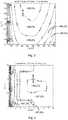
- Figure 3 and figure 4illustrates the efficiencies of the DC/DC converters and the DC/AC inverter of the system of figure 1 .
- the figures 3 and 4illustrate efficiency levels for different power levels and input voltages, and indicate the efficiency levels as areas within each diagram.
- the DC/DC converteris dimensioned to provide the highest efficiency at 800 V.
- the DC/AC inverteris dimensioned to provide the best efficiency for about 2.75 kV.
- the voltage of the PV modules 2a-d (in fig 1 )which is the input voltage of the DC/DC converter 4a-d (in fig 1 ), should be matched to provide the best power transfer through the DC/DC converter 4a-d.
- operating point Aillustrates a situation or state where the voltage is below the voltage of the MPP.
- Operating point Billustrates a situation where the voltage level is above the voltage level of the MPP.
- the embodiments of the inventionemploys both a performance model of each PV array 2a-d, such as the power and voltage relationship of figure 2c , and a theoretical efficiency, model, as in figure 3 , of each DC/DC converter 4a-d when regulating the interface between each DC/DC converter 4a-d and each PV array 2a-d.
- the embodiment of figure 3illustrates an operating point of a PV array 2a-d, which operating point C is indicated in, or mapped into, the efficiency diagram of the DC/DC converter 4a-d.
- the embodiments of the inventionconsider regulating the conversion system, in this case the DC/DC converter, to raise the efficiency of the DC/DC converter, by moving such an operating point C.
- the embodimentstherefore monitor the interface between different devices of the system, such as between the PV array 2a-d and the DC/DC converters 4a-d and regulates the voltage of the interface in view of both devices.
- this regulationmay suitably be made considering also the voltage and power relationship, or performance model, of the PV array 2a-d in question.
- the conversion systemis adapted to monitor the power output from the DC/DC converter 4a-d while adjusting the operating point of the interface of the PV array 2a-d, which adjustment is based on considering the performance model, determined by the voltage and power relationship, of the PV array and the theoretical efficiency, illustrated in figure 3 , of the DC/DC converter.
- the conversion systemis adapted to provide each regulation of the operating point of the PV array 2a-d either in sequence, for example first regulating based on the power voltage relationship of the PV array 2a-d followed by a regulation of the operating point C based on the voltage and power relationship of the DC/DC converter 4a-d, or preferably in combination, wherein the regulation is based on a theoretically determined mapping of the performance model, or voltage and power relationship, of the PV array onto the theoretical efficiency, or the power and voltage relationship, of the DC/DC converter.
- the efficiencies described in figures 3 and 4 of the relationship of the voltage and power of the DC/DC converter and DC/AC inverteris a theoretical model, which however may be provided by measurements, and the described embodiments includes a regular update of these theoretical models by means of measurements performed in the conversion system.
- the theoretical models of the efficienciesmay, in accordance with these embodiments, be defined in the conversion system during installation and be subsequently updated during operation.
- Figure 4illustrate the efficiency of the DC/AC inverter 6, wherein the diagram illustrates the relationship between different DC input voltages and the power.
- the output voltagesuch as at a high voltage, is determined by the transmission grid or transmission link to which the output of the DC/AC inverter 6 is connected.
- An operating point Dis illustrated in the diagram, which corresponds to a voltage level and power level being received at the input of the DC/AC inverter 6 by means of the interface defined by the DC collection grid 5.
- the conversion system of the embodimentsis adapted to regulate the operating point D to provide an enhanced efficiency, which regulation is based on the theoretical efficiency, or relationship, between the input voltage and power of the DC/AC inverter 6, as illustrated in figure 4 .
- the systemis adapted to perform an adjustment of the input voltage of the DC/AC inverter 6 to enhance the efficiency.
- the input voltagemay be adjusted by means of the central controller 14 instructing each local control unit 9a-d of each DC/DC converter 4a-d to adapt their respective output voltage to provide the determined input voltage in accordance with the adjustment of the DC/AC inverter 6.
- the embodiments of the inventiondisclose a regulation for enhancing the efficiency of the power conversion that is carried out in two steps.
- a first stepis performed, wherein the output power of each PV array 2a-d is regulated by the corresponding DC/DC converter 4a-d on the basis of the monitored performance of the PV array 2a-d, the performance model of the array 2a-d and the theoretical efficiency of the DC/DC converter 4a-d.
- a second stepis performed, wherein the input power of the DC/AC converter 6 is regulated in cooperation by all the DC/DC converters 4a-d connected to the input of the DC/AC inverter 6, and which regulation is based on the theoretical efficiency model of the DC/AC inverter 6.
- the output power of the DC/DC converteris monitored during the regulation.
- the output power of the DC/AC inverteris monitored during the regulation. In this way the system can track a maximum efficiency by adjusting the operating points of all the interfaces in the system.
- a straightforward implementation of the first stepis to regulate the input voltage at the input terminals of each DC/DC converter 4a-d, which correspond to the voltage of the PV array 2a-d, in accordance with a theoretical model of the relationship between the voltage and power of the combination of the PV array 2a-d and the (respective) DC/DC converter 4a-d of the PV array 2a-d.
- a straightforward implementation of the second stepis to regulate the input voltage of the DC/AC inverter 6 based on the theoretical efficiency of the DC/AC inverter 6, which regulation is performed by means of the DC/AC inverter adjusting the voltage level of the DC collection grid 5 so that the output voltage of each DC/DC converters 4a-d is regulated to achieve a suitable total voltage input as fed through the collection grid 5 to the DC/AC inverter 6.
- Figure 5 and 6illustrates an embodiment of power conversion in accordance with the invention. This embodiment includes two different modes of operation. The first operating mode is illustrated in figure 5 , and the second operating mode id illustrated in figure 6 .
- the first operating mode (operating mode 1) illustrated in figure 5describes the two steps of regulating the power conversion for increasing efficiency as mentioned above.
- Operating mode 1includes a step of considering switching to the second mode of operation, operating mode 2, which is illustrated in figure 6 .
- Operating mode 1starts with monitoring 101 the power from each PV array 2a-d, the power through each DC/DC converter 4a-d fed by means of the collection grid 5 and the power outputted from the DC/AC inverter 6.
- Mode 1also includes monitoring the input voltage at the input terminals of the DC/AC inverter 6. This monitoring is made to determine if a switch to operating mode 2 should be done. Thus, operating mode 1 continues with determining if the input voltage is too low, i.e. below a first threshold level. The threshold level is set to discover when power losses of the power collecting grid 5 becomes too large, and in such a case switch to the second operating mode 2 for better efficiency.
- step 104in accordance with operating mode 1.
- step 105the interface 3a-d between each PV array 2a-d and each respective DC/DC converter 4a-d is regulated by adjusting the voltage of the interface.
- the operating voltage of each PV array 2a-dis controlled.
- step 105the voltage level is adjusted based on a performance model of the PV array 2a-d and a theoretical efficiency model of each respective DC/DC converter 4a-d, and the regulation step 105 is performed in accordance with the performance models of both the PV array 2a-d in question and of the theoretical efficiency of the corresponding DC/DC converter 4a-d.
- the theoretical models, or their combinationare used to determine whether the voltage should be increased or decreased.
- the regulation step 105 of the operating point of the interface 3a-dincludes evaluating the regulating by monitoring the output power of the respective DC/DC converter 4a-d to determine if the new operating point is better.
- the successfulness of varying the voltageis determined. This is performed by providing the monitored output power of each DC/DC converter 4a-d as a feedback when adjusting the voltage of the respective interfaces 3a-d of each PV array 2a-d.
- An increase in output poweris considered a successful regulation and the new operating point is maintained.
- a decrease in the output power, when moving to a new operating pointis considered an un-successful regulation and the decrease in power is counteracted by a return to the previous operating point.
- step 106the operating point of the interface 5 between the output of all the DC/DC converters 4a-d and the input of the DC/AC inverter 6 is regulated.
- This regulation step 106is based on the theoretical performance of the DC/AC inverter 6.
- Regulating step 106includes evaluating the regulation of the operating point of the interface between the DC/DC converters 4a-d and the DC/AC inverter 6 by monitoring the output power of the DC/AC inverter 6. A feedback of the monitored output power and/or its variation is provided in the regulation step 106. Thus, the regulation is adjusted on the basis of the output power from the DC/AC inverter 6.
- Operating mode 1, of figure 5includes an optional step of updating the theoretical models of the performances of each PV array 2a-d, of the efficiencies of each DC/DC converter 4a-d and of the efficiency of the DC/AC inverter 6. This is done by means of the measurements in the system such as including measurements of the voltages and currents of each PV array 2a-d output, such as measured at the corresponding DC/DC converter input 4a-d, each DC/DC converter 4a-d input and output and the input and output of the DC/AC inverter 6.
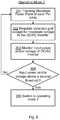
- Figure 6illustrates operating mode 2, which is used when the input voltage, or power, of the DC/AC inverter 6 falls below a threshold that can be interpreted as corresponding to a too small power from the PV arrays 2a-d in relation to power losses of the conversion system so that a tracking of a maximum power point of the total conversion system cannot be performed.
- the power or currentis monitored.
- the method of operationmay then switch to an operating mode 2 of keeping the input voltage of the DC/AC inverter 6 at a high level to keep down the power losses of the DC collection grid 5.
- Operating mode 2suitably starts with tracking the maximum power points of each PV array 2a-d to provide a maximum input power into the conversion system.
- the DC/DC converters 4a-dare regulated for providing a predefined maximum voltage input at the DC/AC inverter 6.
- the input voltage of the DC/AC inverter 6is monitored, in step 303, and operating mode 2 is continued until the operating point of power and input voltage of the DC/AC inverter 6 reaches above a second threshold in which case the operation of the conversion system returns to operating mode 1.
- operating mode 2includes a step 304 of determining if the power and/or input voltage are/is above a second threshold, in which case the operating mode 2 continues with step 305.
- the operating mode 2continues by returning to the step 301 of tracking the maximum power point of each PV array 2a-d followed by the step of regulating 302 the DC/DC converters 4a-d to increase the power and/or input voltage of the DC/AC inverter 6. However, if the power or voltage is determined in step 304 to having reach above the second threshold, operating mode 2 continues with a step 305 of switching to operating mode 1.
- Both the operating modesmay suitably be performed by means of the central controller 14 communicatively and operatively connected to each local control unit 9a-d, 10 and which controller 14 may be adapted to perform the method steps by instructing each respective control unit 9a-d, 10 to provide measurements and perform the control of each respective device, i.e. each respective DC/DC converter or the DC/AC inverter, in accordance with the described methods.
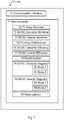
- Figure 7illustrates an embodiment wherein a control unit 10 of a DC/AC inverter 6 provides a central control of the power conversion system. A central control unit 14 may then be omitted.
- Figure 7provides an illustration of the main functions of the embodiment when the invention is implemented, but has been simplified and do not illustrate the basic functions of a DC/AC inverter for providing the power conversion from DC to AC as such. These functions can suitably be implemented as software that when executed in the DC/AC inverter control unit 10 controls the control unit 10 to control the DC/AC inverter to provide the functions in the disclosed method.
- the control unit 10 of the DC/AC invertercomprises a communication interface 70 for communicating and operatively controlling the DC/AC inverter 6 and the DC/DC converters 4a-d as well as receiving measurements from the inputs and outputs of each DC/DC converter 4a-d and the DC/AC inverter 6.
- the control unit 10includes a main controller 71, such as a computer with processor and memory, for effectuating the specific functions.
- the main controller 71includes a PV array monitorer 72, a DC/DC converter monitorer 73 and a DC/AC inverter monitorer 74 so that the control unit 10 is configured to monitor the voltages and currents (or voltages and powers) of each respective device, i.e.
- the main controller 71is also configured with a number of theoretical models and configured to use the models for performing the regulating steps; i.e. a PV array performance model 75, a DC/DC converter efficiency model 76 and a DC/AC inverter efficiency model 77. As described in relation to the method, these theoretical models should be updated during operation, and for this purpose, the main controller 71 comprises a model updater 78, provided to update each model 75, 76, 77 in view of the measurements provided by the monitoring elements 72, 73, 74.
- the main controlleralso includes two regulators 79, 82, each having two modes of operation; mode 1 and mode 2, respectively, which modes are selected by means of a mode selector 85.
- the first regulatoris a DC/DC converter regulator 82 configured to control each of the DC/DC converters 4a-d in accordance with the method of the invention, operating according to mode 1 and mode 2.
- the DC/DC converter regulator 79is configured to use, in mode 1, the voltages and currents of each PV array 2a-d as provided by means of the PV array monitorer 72 to regulate each DC/DC converter 4a-d.
- the DC/DC converter regulator 79is also configured to use the performance model 75 of each PV array 2a-d and the efficiency model 76 of each DC/DC converter 4a-d, to regulate the voltage of the interface between each PV array 2a-d and each DC/DC converter 4a-d by means of using the output voltage of each DC/DC converter 4a-d as feedback, which output voltage is provided by means of the DC/DC converter monitorer 73.
- the DC/DC converter regulator 79is configured to use, in mode 2, the voltages and currents of each PV array 2a-d as provided by the PV monitorer 72 together with the performance model of the PV array 75 to perform a maximum power point tracking of each PV array 2a-d.
- the DC/AC inverter 6is controlled by the DC/AC inverter regulator 82 to set the collection grid 5 voltage at a predefined maximum level, in mode 2.
- the DC/AC inverter regulator 82is configured to regulate the voltage of the conversion grid 5, or input of the DC/AC inverter 6 on the bases of the theoretical efficiency model 77 of the DC/AC inverter 6, while using the monitored output voltage, as provided by the DC/AC monitorer 74, as a feedback for the regulation.
- the DC/AC inverter regulatoris configured to monitor the input in view of the theoretical efficiency model 77, or differently described, to map the input operating point of the conversion grid 5 on the efficiency model 77 of the DC/AC inverter 6, and using the monitored output of the DC/AC inverter, as monitored by means of the DC/AC inverter monitorer 76, as a feedback for the regulation.
- the main controller 71may also suitably include means for monitoring or receiving information of the transmission grid, such as reactive power, and may provide compensation of reactive power, or provide filtering functions, in the transmission grid; however such functioning is not described in this disclosure.
- the main controller 71also includes a mode selector 85 configured for providing the switching between operating mode 1 and operating mode 2.
- the mode selectorbeing configured to use input voltage and current/power of the DC/AC inverter 6, as obtained by the DC/AC inverter monitorer 74, for selecting operating mode based on a criteria, such as a threshold level for the input voltage, and/or current and/or power.
- figure 7illustrates the alternative embodiment of the central control functions that a central control unit 14 should perform to when regulating the power conversion system.
- the central control unit 14controls the DC/AC inverter via its "local" control unit 10.
Landscapes
- Engineering & Computer Science (AREA)
- Power Engineering (AREA)
- Inverter Devices (AREA)
- Control Of Electrical Variables (AREA)
Description
- The present disclosure relates to a method, a power conversion system, and a DC/AC inverter for a solar power plant.
- In a typical solar power plant, solar power are collected by a plurality of photovoltaic (PV) devices or panels transforming the solar power into DC (direct current) electric power, which power is subsequently converted into AC (alternating current) electric power of a power transmission system or grid.
- The power is collected at a low voltage by the PV panels, converted into a higher voltage and fed to the transmission system. To provide the conversion a complex system is used incorporating many devices and to maximize efficiency different collecting and conversion systems have been used.
US 2012/0274139 (E1 ) describes a distributed PV power plant including a plurality of distributed DC/DC converters (22 in E1), each being connected to a plurality of strings of PV panels. The switching of the DC/DC converters is coordinated, and their power are supplied to a common DC bus for further conversion by means of a DC/AC converter into AC power (seefigure 1-4 ,claim 1 of E1). By coordinating the switching of the local DC/DC converters a higher efficiency can be provided (see §0032, §0036 in E1).- Another method and system for enhancing efficiency is disclosed in
US2011/0160930 (E2 ). Document E2 describes a solar power plant comprising photovoltaic panels (PV panels) (20 infigure 3 of E2), local power converters (22 in E2) and a central power converter (24 in E2). So called maximum power point tracking (MPPT) is provided for each power source, i.e. for each PV panel, by means of the local power converters (22, see §0006, §0021, see alsofigure 4 andfigure 5 in E2). The central converter (24) also includes MPP tracking (see §0025,claim 1 in E2), and the two methods of MPP tracking are coordinated (see §0061, figures 16-18) in E2. Such a system has benefits during for example shading, but the provision of one dedicated local converter for each panel adds costs to the overall system, especially for larger systems. - It is an objective of the present disclosure to at least alleviate a problem in the prior art in respect of energy production. An aim of the invention is to provide high efficiency in solar power systems. A further aim is to provide a cost effective system.
- For these purposes the present invention provides a method of controlling a solar power plant comprising photovoltaic modules (PV modules) and a power conversion system arranged to convert the power collected by the PV modules for transmission by means of an electric power transmission system. The conversion system comprises a plurality of DC/DC converters, a power collecting grid and a DC/AC inverter, and the PV modules are arranged in arrays of PV modules, each PV array having an interface connected to, and controlled by, a respective one of the DC/DC converters, the power collecting grid being arranged to provide an interface between the plurality of DC/DC converters and an input of the DC/AC inverter (6). The method comprises monitoring the performance of each PV array and performing a first mode of operation. The first mode of operation comprises a first step of regulating, wherein the voltage level of each interface between a PV array and the corresponding DC/DC converter is adjusted, which regulating is based on a performance model of the PV array and a theoretical efficiency of each DC /DC converter, and includes monitoring the output power of each DC/DC converter during the first step of regulating and use the monitored output power of each DC /DC converter as a feedback for controlling the first regulating step. The first mode of operation also comprises a second step of regulating, wherein the voltage level of the power collecting grid is adjusted, which regulating is based on a theoretical efficiency of the DC/AC inverter, and includes monitoring the output power of the DC/AC inverter, during the second step of regulating and use the monitored output power of the DC/AC inverter as a feedback for controlling the second regulating step.
- In an embodiment, the method includes selectively employing the first mode of operation or a second mode of operation. The second mode of operation comprises controlling the voltage level of the power collection grid so that the DC/DC converters provide power at a predefined maximum output voltage to increase the input voltage and power of the DC/AC inverter. In this way an efficient alternative exists when the first mode encounter problems.
- In an embodiment, the method includes switching to the second mode of operation when the input voltage, or power, of the DC/AC inverter falls below a first threshold. In this way, the method can function also when, for example, the power production is small and losses in the power conversion grid affect its current transferring capacity.
- In an embodiment, the second mode of operation includes controlling the DC/DC converters to perform a maximum power point tracking of each PV array.
- In an embodiment, the method includes updating the theoretical efficiency of each primary DC /DC converter and/or updating the theoretical efficiency of the DC/AC inverter. In this way the method adapts to varying conditions of the conversion system, such as losses in different parts of the system due to for example ageing, and failures of components. This provides a step of learning being employed to adapt the functioning automatically to different conditions.
- In an embodiment, the method includes converting the power from the PV arrays into DC power at a medium voltage by means of the DC/DC converters. The medium voltage level is between 2kV and 50 kV. The method includes feeding the medium voltage power to the DC/AC inverter by means of the power collecting grid.
- The present invention also provides a power conversion system for a solar power plant, adapted for converting power collected by PV modules of the solar power plant to AC power for transmission by means of an electric power transmission system. The power conversion system comprises a plurality of DC/DC converters, a power collecting grid and a DC/AC inverter. Each DC/DC converter is adapted to be connected to and control an interface to an array of PV modules. Each DC/DC converter may have a plurality of interfaces, each controlling an array of PV modules. The power collecting grid is arranged between the plurality of DC/DC converters and an input of the DC/AC inverter and provides an interface between the DC/DC converters and the DC/AC inverter. The conversion system further comprises at least one control unit arranged and adapted to control the conversion of power. The at least one control unit is adapted to monitor the performance of each PV array, and to perform a first mode of operation comprising a first and a second regulating step. The first step of regulating includes adjusting the voltage level of each interface between a PV array and the corresponding DC/DC converter, The first step of regulating is based on a performance model of the PV array and a theoretical efficiency of each DC /DC converter and includes monitoring the output power of each primary DC/DC converter and uses the monitored output power of each DC /DC converter as a feedback for the first step of regulating. The second step of regulating includes adjusting the voltage level of the power collecting grid. The second step of regulating is based on a theoretical efficiency of the DC/AC inverter and includes monitoring the output power of the DC/AC inverter and uses the monitored output power of the DC/AC inverter as a feedback for the second step of regulating.
- In an embodiment, the at least one control unit is adapted to selectively employ the first mode of operation or a second mode of operation. The second mode of operation comprises controlling the DC/AC inverter to adjust its input voltage, so that the DC/DC converters provide the power at a predefined maximum output voltage.
- In an embodiment, the at least one control unit is adapted to switch to the second mode of operation when the input power or voltage of the DC/AC inverter falls below a first threshold.
- In an embodiment, the second mode of operation comprises controlling the DC/DC converters to perform a maximum power point tracking of each PV array.
- In an embodiment, the at least one control unit is adapted to update the performance model of each PV array and/or the theoretical efficiency of each primary DC /DC converter and/or update the theoretical efficiency of the DC/AC inverter.
- In an embodiment, each DC/DC converter comprises a control unit, and the at least one control unit is a central control unit that is operatively connected to each control unit of the DC/DC converters and is adapted to control the first step of regulating by instructing each control unit of the DC/DC converters.
- In an embodiment the DC/AC inverter comprises a control unit, and the at least one control unit is a central control unit operatively connected to the control unit of the DC/AC inverter and is adapted to control the second step of regulating by means of instructing the control unit of the DC/AC inverter.
- In an embodiment the power collecting grid is adapted for collecting DC power at a medium voltage level, such as between 2kV and 50 kV, and the DC/AC inverter is a medium voltage DC/AC inverter.
- In an embodiment each DC/DC converter is an isolated DC/DC converter.
- In an embodiment, a power conversion system comprises two power conversion systems as described above. Each of the two power conversion systems provides power by means of its respective DC/AC inverter to the power transmission system.
- The present invention also provides a DC/AC inverter for converting medium voltage DC current into medium or high voltage AC current, which DC/AC inverter is also adapted for controlling power conversion of a solar power plant.
- The DC/AC inverter controls a solar power plant comprising photovoltaic modules (PV modules) arranged in arrays of PV modules, each PV array (2a-d) being connected to a corresponding one of a plurality of DC/DC converters (4a-d), the DC/DC converters being connected in a power collecting grid to the DC/AC inverter. Especially, the DC/AC inverter comprises a control unit configured to control the DC/AC inverter. The control unit is configured to be connected to the plurality of the DC/DC converters, the control unit is configured to operatively control each DC/DC converter and operatively control the voltage of each respective interface to respective the PV array by means of the DC/DC converter. The control unit is adapted to monitor the performance of each PV array, and to perform a first mode of operation. The first mode of operation comprises a first step of regulating, wherein the voltage level of each interface between a PV array and the corresponding DC/DC converter is adjusted, which regulating is based on a performance model of the PV array and a theoretical efficiency of each DC /DC converter, and includes monitoring the output power of each primary DC/DC converter during the first step of regulating and using the monitored output power of each DC /DC converter as a feedback for the first step of regulating. The first mode of operating includes a second step of regulating. The second step of regulating includes adjusting the voltage level of the power collecting grid. The second step of regulating is based on a theoretical efficiency of the DC/AC inverter, and includes monitoring the output power of the DC/AC inverter, during the second step of regulating and using the monitored output power of the DC/AC inverter (6) as a feedback for the second step of regulating.
- In an embodiment of the DC/AC inverter, the control unit comprises a memory storing a performance model of each PV array, an efficiency model of each DC/DC converter, an efficiency model of the DC/AC inverter, and a model updater configured for updating each model based on measurements of the corresponding unit.
- In an embodiment of the DC/AC inverter, the control unit comprises a DC/DC converter regulator configured to control each DC/DC converter in accordance with the first step of regulating, and a DC/AC inverter regulator configured to control the DC/AC inverter in accordance with the second step of regulating.
- In an embodiment of the DC/AC inverter, the control unit comprises a mode selector configured to switch between the first mode of operation and a second mode of operation, in which second mode of operation the DC/AC inverter is controlled to set a voltage level of the DC collection grid so that the DC/DC converters provide the output power at a predefined maximum output voltage in order to increase the input power of the DC/AC inverter.
- The present invention also provides a solar power plant that comprises a plurality of PV modules arranged and interconnected into a plurality of PV arrays, and a power conversion system of the kind described above, wherein each PV array have an interface connected to, and controlled by, a respective DC/DC converter of the power conversion system.
- The invention is now described, by way of example, with reference to the accompanying drawings, in which:
- Fig 1a is a schematic illustration of a first embodiment a solar power plant with high voltage AC connection to a transmission system.
Fig 2a, 2b ,2c are graphs illustrating the maximum power point of a PV panel.Fig 3 is an illustration of a DC/DC converter efficiency contour.Fig 4 is an illustration of a medium voltage DC/AC inverter efficiency contour.Fig 5 is a schematic illustration of an operating method according to an embodiment of the invention.Fig 6 is a schematic further illustration of an operating method according to an embodiment of the invention.Fig 7 is a schematic illustration of an embodiment of a controller for a DC/AC inverter in accordance with the invention.- The invention will now be described more fully hereinafter with reference to the accompanying drawings, in which certain embodiments of the invention are shown. This invention may, however, be embodied in many different forms and should not be construed as limited to the embodiments set forth herein; rather, these embodiments are provided by way of example so that this disclosure will be thorough and complete, and will fully convey the scope of the invention to those skilled in the art.
Figure 1 illustrates asolar power plant 1 comprising a plurality of PV (photovoltaic)arrays PV array 2a-d comprises a plurality of interconnected PV panels. Each PV panel consists of one unit comprising interconnected photovoltaic cells. Each PV panel is arranged to receive energy from sun light and transform the energy into electric DC energy. Each PV array should typically include many PV panels, for example hundreds or more than one thousand panels to produce DC power of about 0.5-3 MW. For clarity purposes, the figure do not illustrate the PV panels in eachPV array 2a-d, but the number of PV panels in eachPV array 2a-d may be between 3000 to 10000 panels, for example 8000 PV panels in 320 parallel lines with 25 PV panels serially connected in each line. The PV panels of eachPV array 2a-d are arranged in series and in parallel to produce the electric DC power at an output (3a-d) of about 1000 V, such as up to 1.5 kV. For example, each PV panel produce 250 W and 8000 PV panels produce 2 MW. In this example 320 parallel lines PV panels producing DC electric power at 3.125 V yields a total of 1 kV at the common output (3a-d) of the PV panels of eachPV array 2a-d. By the interconnections of the PV panels into an array of PV panels, a first set of DC collection systems are provided, each of these DC collection systems being referred to as aPV array 2a-d.- The
solar power plant 1 also comprises a plurality of DC/DC converters DC converter 4a-d has a respective input (3a-d) connected to the output of arespective PV array 2a-d, so that arespective interface 3a-d between each DC/DC converter and each PV array is provided. The outputs of the DC/DC converters 4a-d are serially connected to provide aDC output grid 5 at a medium voltage power level. The total power outputted from the connected DC/DC converters 4a-d are provided to an input of a DC/AC inverter 6. By the interconnection of the DC/DC converters 4a-d to a common output (5) a second DC collection system,grid 5, is provided, at a medium voltage level. The term "medium voltage" refers to voltage levels above 2 kV and below 60 kV, especially voltage levels between 3 kV and 45 kV. Each DC/DC converter 4a-d is an isolated DC/DC converter arranged to provide galvanic isolation between eachPV array 2a-d and the medium voltageDC collection grid 5. The system includes arranging the DC/AC inverter 6 to receive the medium voltage DC power from thecollection grid 5 by means of its DC input. Thus, each DC/DC converter 4a-d is connected to arespective PV array 2a-d at its input, and the outputs of the DC/DC converters 4a-d are connected in series and provide a medium high voltage DC output connected to the input of the DC/AC inverter 6, so that the secondDC collection grid 5 provides an interface between the outputs of the DC/DC converters 4a-d and the DC/AC inverter 6.. - The
output 8 of the DC/AC inverter provides AC power for subsequent transmission on an AC transmission system (not illustrated), via atransformer 12, whichtransformer 12 provides galvanic insulation between the power conversion and collection system and the AC transmission system. - Thus, the solar power plant collects solar energy and converts the produced electrical DC power from the PV arrays of low voltage DC power to a high voltage AC power at the
output 8 of the medium voltage DC/AC inverter 6 by means of a DC power conversion andcollection system 4, 5 and the DC/AC inverter 6. Alternatively the DC/AC inverter 6 is a medium to medium voltage inverter, instead of a medium to high voltage DC/AC inverter 6. This DC power conversion system comprises a set of DC/DC converters 4a-d with a low voltage DC input, and a medium voltage DC arrangement in the form of a medium voltageDC collection grid 5 arranged for feeding DC power of medium voltage to the medium voltage DC/AC inverter 6. - Thus, a low voltage DC input, such as up to 1000 V or 1.5 kV, is converted to a medium
voltage collection grid 5, a DC medium voltage of about 3 kV to 45 kV which in turn preferably is converted to a high voltage AC (or alternatively medium voltage AC power) of about 60 kV or more. - Using only two power conversion steps is a means both for reducing costs and reducing power losses during operation.
- The solar power plant also includes a number of control units (9a-d, 10, 14) being arranged and adapted for controlling the functioning of the power collection and power conversion. The DC/AC inverter is provided with a
controller 10, and each of the DC/DC converters is provided with arespective controller 9a-d. Eachcontroller 9a-d of the DC/DC converters 4a-d is adapted for controlling the conversion of low voltage DC, from each respective array, into the medium voltage DC power that is collected by means of the serial interconnection of theDC collection grid 5 and fed to the DC/AC inverter 6. The DC/AC inverter 6 is provided with acontroller 10 adapted for converting medium voltage DC power into AC power of a high, or medium, voltage level in accordance with the AC transmission grid. To provide an efficient overall power conversion system, the power system also includes acentral controller 14, which is communicatively connected to each "local"controller 9a-d of each DC/DC converter 4a-d and thecontroller 10 of the DC/AC inverter 6. - It is possible to omit the
central controller 14, and adapt one or more of thecontrollers 9a-d, 10 of the DC/DC converters 4a-d or the DC/AC inverter 6 to provide the central control functions. However, this is not illustrated infigure 1 . - The
central controller 14 is adapted to obtain, or receive, operating information of each DC/DC converter 4a-d and the DC/AC inverter 6, which operating information is obtained at the respective inputs and outputs of theconverters 4a-d andinverter 6. TheController 14 is adapted to use the measurements and operating information provided from thelocal control units 9, 10 to perform an overall system control to obtain an overall power efficient operation of the whole power conversion system and the solar power plant. - The central control functions will be described in more detail with reference to
figures 2-7 , and acentral controller 14 is suggested for adapting the conversion system to function in accordance with the methods of the exemplifying embodiments of the invention.Figure 7 suggests implementing the central control functions in thecontrol unit 10 of the DC/AC inverter 6. Figures 2a-c illustrates the maximum power point of a PV panel or PV module. These figures illustrate the relationship between the voltage of a PV module and the current and power of the PV module. The invention suggests controlling a PV array, i.e.arrays 2a-d of PV modules connected in series and parallel. The control of such aPV array 2a-d can utilise corresponding relationships for aPV array 2a-d of PV modules, which array relationships are determined by summarizing the relationships of the PV modules of thePV array 2a-d. The relationship so obtained provides a description, or model, of the performance of thePV array 2a-d at varying voltage and power levels.Figures 2a is a current-voltage curve that illustrates how the current fed from a PV module varies with a voltage applied to the output of the PV module.Figure 2b is a power-voltage curve and illustrates how the power from the PV module varies with the applied voltage.Figure 2c illustrates both the current-voltage and the power-voltage curves. The point where the transferred power has a maximum is indicated in each curve. This is the maximum power point and for each state of the PV module the maximum power point can be tracked to provide the maximum power output of that state. However, tracking the maximum power output of the PV module may not lead to the maximum power output of a total conversion system or a whole solar power plant.- The conversion system of a solar power plant should be dimensioned to transfer as much power as possible to the power transmission system or power grid. Also the efficiency of the power conversion system of the solar power plant varies with different voltages and power levels. The power conversion system may therefore operate in a non-optimal state even if the PV modules operate at the maximum power point. The invention provides systems and methods for matching the efficiency of the PV modules and the conversion system to reach an overall maximum power transfer from the PV modules to the power transmission grid.
Figure 2c also indicate operating points, A and B, of a PV module, which operating points A, B, differ from the maximum power point (MPP) of the PV module. When tracking the MPP, voltage levels (such as A and B) that for the current state differs from the MPP are adjusted to match the MPP. However, the embodiments of the present invention considers the total efficiency of the conversion system and may therefore regulate one or more of thePV arrays 2a-d to operate at an operating point A, B that differ from the MPP.Figure 3 and figure 4 illustrates the efficiencies of the DC/DC converters and the DC/AC inverter of the system offigure 1 . Thefigures 3 and 4 illustrate efficiency levels for different power levels and input voltages, and indicate the efficiency levels as areas within each diagram. As can be seen fromfigure 3 , the DC/DC converter is dimensioned to provide the highest efficiency at 800 V. As can be seen fromfigure 4 , the DC/AC inverter is dimensioned to provide the best efficiency for about 2.75 kV. In accordance with the embodiments of the invention, the voltage of thePV modules 2a-d (infig 1 ) which is the input voltage of the DC/DC converter 4a-d (infig 1 ), should be matched to provide the best power transfer through the DC/DC converter 4a-d. Fromfigures 2a-c it is apparent that raising the voltage decrease the current from the PV modules and for voltages above the maximum power point voltage, a voltage increase leads to a power decrease. Fromfigure 3 it can be seen that for operating points at voltages lower than 800 V, raising the voltage also provides the best efficiency in general for the DC/DC converter. Thus, an increase in voltage for the DC/DC converter, to increase its efficiency should be made in view of the fact that the voltage increase may lead to a decreasing power being fed from the PV modules of the PV array.- Returning to
figure 2c , operating point A illustrates a situation or state where the voltage is below the voltage of the MPP. Operating point B, on the other hand, illustrates a situation where the voltage level is above the voltage level of the MPP. - The embodiments of the invention employs both a performance model of each
PV array 2a-d, such as the power and voltage relationship offigure 2c , and a theoretical efficiency, model, as infigure 3 , of each DC/DC converter 4a-d when regulating the interface between each DC/DC converter 4a-d and eachPV array 2a-d. - The embodiment of
figure 3 illustrates an operating point of aPV array 2a-d, which operating point C is indicated in, or mapped into, the efficiency diagram of the DC/DC converter 4a-d. The embodiments of the invention consider regulating the conversion system, in this case the DC/DC converter, to raise the efficiency of the DC/DC converter, by moving such an operating point C. The embodiments therefore monitor the interface between different devices of the system, such as between thePV array 2a-d and the DC/DC converters 4a-d and regulates the voltage of the interface in view of both devices. Thus, this regulation may suitably be made considering also the voltage and power relationship, or performance model, of thePV array 2a-d in question. The conversion system is adapted to monitor the power output from the DC/DC converter 4a-d while adjusting the operating point of the interface of thePV array 2a-d, which adjustment is based on considering the performance model, determined by the voltage and power relationship, of the PV array and the theoretical efficiency, illustrated infigure 3 , of the DC/DC converter. Thus, the conversion system is adapted to provide each regulation of the operating point of thePV array 2a-d either in sequence, for example first regulating based on the power voltage relationship of thePV array 2a-d followed by a regulation of the operating point C based on the voltage and power relationship of the DC/DC converter 4a-d, or preferably in combination, wherein the regulation is based on a theoretically determined mapping of the performance model, or voltage and power relationship, of the PV array onto the theoretical efficiency, or the power and voltage relationship, of the DC/DC converter. - It should be noted that the efficiencies described in
figures 3 and 4 of the relationship of the voltage and power of the DC/DC converter and DC/AC inverter is a theoretical model, which however may be provided by measurements, and the described embodiments includes a regular update of these theoretical models by means of measurements performed in the conversion system. The theoretical models of the efficiencies may, in accordance with these embodiments, be defined in the conversion system during installation and be subsequently updated during operation. Figure 4 illustrate the efficiency of the DC/AC inverter 6, wherein the diagram illustrates the relationship between different DC input voltages and the power. The output voltage, such as at a high voltage, is determined by the transmission grid or transmission link to which the output of the DC/AC inverter 6 is connected. An operating point D is illustrated in the diagram, which corresponds to a voltage level and power level being received at the input of the DC/AC inverter 6 by means of the interface defined by theDC collection grid 5. The conversion system of the embodiments is adapted to regulate the operating point D to provide an enhanced efficiency, which regulation is based on the theoretical efficiency, or relationship, between the input voltage and power of the DC/AC inverter 6, as illustrated infigure 4 .- Accordingly, the system is adapted to perform an adjustment of the input voltage of the DC/
AC inverter 6 to enhance the efficiency. The input voltage may be adjusted by means of thecentral controller 14 instructing eachlocal control unit 9a-d of each DC/DC converter 4a-d to adapt their respective output voltage to provide the determined input voltage in accordance with the adjustment of the DC/AC inverter 6. - The embodiments of the invention disclose a regulation for enhancing the efficiency of the power conversion that is carried out in two steps. A first step is performed, wherein the output power of each
PV array 2a-d is regulated by the corresponding DC/DC converter 4a-d on the basis of the monitored performance of thePV array 2a-d, the performance model of thearray 2a-d and the theoretical efficiency of the DC/DC converter 4a-d. A second step is performed, wherein the input power of the DC/AC converter 6 is regulated in cooperation by all the DC/DC converters 4a-d connected to the input of the DC/AC inverter 6, and which regulation is based on the theoretical efficiency model of the DC/AC inverter 6. In the first step, the output power of the DC/DC converter is monitored during the regulation. In the second step, the output power of the DC/AC inverter is monitored during the regulation. In this way the system can track a maximum efficiency by adjusting the operating points of all the interfaces in the system. - A straightforward implementation of the first step is to regulate the input voltage at the input terminals of each DC/
DC converter 4a-d, which correspond to the voltage of thePV array 2a-d, in accordance with a theoretical model of the relationship between the voltage and power of the combination of thePV array 2a-d and the (respective) DC/DC converter 4a-d of thePV array 2a-d. A straightforward implementation of the second step is to regulate the input voltage of the DC/AC inverter 6 based on the theoretical efficiency of the DC/AC inverter 6, which regulation is performed by means of the DC/AC inverter adjusting the voltage level of theDC collection grid 5 so that the output voltage of each DC/DC converters 4a-d is regulated to achieve a suitable total voltage input as fed through thecollection grid 5 to the DC/AC inverter 6. Figure 5 and6 illustrates an embodiment of power conversion in accordance with the invention. This embodiment includes two different modes of operation. The first operating mode is illustrated infigure 5 , and the second operating mode id illustrated infigure 6 .- The first operating mode (operating mode 1) illustrated in
figure 5 describes the two steps of regulating the power conversion for increasing efficiency as mentioned above.Operating mode 1 includes a step of considering switching to the second mode of operation, operatingmode 2, which is illustrated infigure 6 . Operating mode 1 starts with monitoring 101 the power from eachPV array 2a-d, the power through each DC/DC converter 4a-d fed by means of thecollection grid 5 and the power outputted from the DC/AC inverter 6.Mode 1 also includes monitoring the input voltage at the input terminals of the DC/AC inverter 6. This monitoring is made to determine if a switch to operatingmode 2 should be done. Thus, operatingmode 1 continues with determining if the input voltage is too low, i.e. below a first threshold level. The threshold level is set to discover when power losses of thepower collecting grid 5 becomes too large, and in such a case switch to thesecond operating mode 2 for better efficiency.- Thus, if the voltage level is too low, the system is adapted to switch to operating
mode 2,step 104, in accordance withoperating mode 1. - If the voltage level is satisfactory,
operating mode 1 continues with two steps of regulating. In thefirst step 105, theinterface 3a-d between eachPV array 2a-d and each respective DC/DC converter 4a-d is regulated by adjusting the voltage of the interface. Thus the operating voltage of eachPV array 2a-d is controlled. According to step 105, the voltage level is adjusted based on a performance model of thePV array 2a-d and a theoretical efficiency model of each respective DC/DC converter 4a-d, and theregulation step 105 is performed in accordance with the performance models of both thePV array 2a-d in question and of the theoretical efficiency of the corresponding DC/DC converter 4a-d. Especially, the theoretical models, or their combination, are used to determine whether the voltage should be increased or decreased. - The
regulation step 105 of the operating point of theinterface 3a-d includes evaluating the regulating by monitoring the output power of the respective DC/DC converter 4a-d to determine if the new operating point is better. Thus, in view of the variations of the output power of each DC/DC converter 4a-d the successfulness of varying the voltage is determined. This is performed by providing the monitored output power of each DC/DC converter 4a-d as a feedback when adjusting the voltage of therespective interfaces 3a-d of eachPV array 2a-d. An increase in output power is considered a successful regulation and the new operating point is maintained. A decrease in the output power, when moving to a new operating point, is considered an un-successful regulation and the decrease in power is counteracted by a return to the previous operating point. - In
step 106 the operating point of theinterface 5 between the output of all the DC/DC converters 4a-d and the input of the DC/AC inverter 6 is regulated. Thisregulation step 106 is based on the theoretical performance of the DC/AC inverter 6. Regulatingstep 106 includes evaluating the regulation of the operating point of the interface between the DC/DC converters 4a-d and the DC/AC inverter 6 by monitoring the output power of the DC/AC inverter 6. A feedback of the monitored output power and/or its variation is provided in theregulation step 106. Thus, the regulation is adjusted on the basis of the output power from the DC/AC inverter 6. Operating mode 1, offigure 5 , includes an optional step of updating the theoretical models of the performances of eachPV array 2a-d, of the efficiencies of each DC/DC converter 4a-d and of the efficiency of the DC/AC inverter 6. This is done by means of the measurements in the system such as including measurements of the voltages and currents of eachPV array 2a-d output, such as measured at the corresponding DC/DC converter input 4a-d, each DC/DC converter 4a-d input and output and the input and output of the DC/AC inverter 6.Figure 6 illustrates operatingmode 2, which is used when the input voltage, or power, of the DC/AC inverter 6 falls below a threshold that can be interpreted as corresponding to a too small power from thePV arrays 2a-d in relation to power losses of the conversion system so that a tracking of a maximum power point of the total conversion system cannot be performed. Alternatively, or additionally, the power or current is monitored. During low power levels, as obtained at thePV arrays 2a-d, a successful tracking of a search for a maximum efficiency may not be suitable. In accordance with the embodiment offigure 5 , the method of operation may then switch to anoperating mode 2 of keeping the input voltage of the DC/AC inverter 6 at a high level to keep down the power losses of theDC collection grid 5.Operating mode 2 suitably starts with tracking the maximum power points of eachPV array 2a-d to provide a maximum input power into the conversion system. Instep 302 the DC/DC converters 4a-d are regulated for providing a predefined maximum voltage input at the DC/AC inverter 6. The input voltage of the DC/AC inverter 6 is monitored, instep 303, andoperating mode 2 is continued until the operating point of power and input voltage of the DC/AC inverter 6 reaches above a second threshold in which case the operation of the conversion system returns to operatingmode 1. Thus operatingmode 2 includes astep 304 of determining if the power and/or input voltage are/is above a second threshold, in which case the operatingmode 2 continues withstep 305. If the input voltage is determined as still being lower than the second threshold, the operatingmode 2 continues by returning to thestep 301 of tracking the maximum power point of eachPV array 2a-d followed by the step of regulating 302 the DC/DC converters 4a-d to increase the power and/or input voltage of the DC/AC inverter 6. However, if the power or voltage is determined instep 304 to having reach above the second threshold,operating mode 2 continues with astep 305 of switching to operatingmode 1.- Both the operating modes may suitably be performed by means of the
central controller 14 communicatively and operatively connected to eachlocal control unit 9a-d, 10 and whichcontroller 14 may be adapted to perform the method steps by instructing eachrespective control unit 9a-d, 10 to provide measurements and perform the control of each respective device, i.e. each respective DC/DC converter or the DC/AC inverter, in accordance with the described methods. Figure 7 illustrates an embodiment wherein acontrol unit 10 of a DC/AC inverter 6 provides a central control of the power conversion system. Acentral control unit 14 may then be omitted.Figure 7 provides an illustration of the main functions of the embodiment when the invention is implemented, but has been simplified and do not illustrate the basic functions of a DC/AC inverter for providing the power conversion from DC to AC as such. These functions can suitably be implemented as software that when executed in the DC/ACinverter control unit 10 controls thecontrol unit 10 to control the DC/AC inverter to provide the functions in the disclosed method.- The
control unit 10 of the DC/AC inverter comprises acommunication interface 70 for communicating and operatively controlling the DC/AC inverter 6 and the DC/DC converters 4a-d as well as receiving measurements from the inputs and outputs of each DC/DC converter 4a-d and the DC/AC inverter 6. Thecontrol unit 10 includes amain controller 71, such as a computer with processor and memory, for effectuating the specific functions. Themain controller 71 includes aPV array monitorer 72, a DC/DC converter monitorer 73 and a DC/AC inverter monitorer 74 so that thecontrol unit 10 is configured to monitor the voltages and currents (or voltages and powers) of each respective device, i.e. eachPV array 2a-d, each DC/DC converter 4a-d, and the DC/AC inverter 6. Themain controller 71 is also configured with a number of theoretical models and configured to use the models for performing the regulating steps; i.e. a PVarray performance model 75, a DC/DCconverter efficiency model 76 and a DC/ACinverter efficiency model 77. As described in relation to the method, these theoretical models should be updated during operation, and for this purpose, themain controller 71 comprises amodel updater 78, provided to update eachmodel monitoring elements - The main controller also includes two
regulators mode 1 andmode 2, respectively, which modes are selected by means of amode selector 85. The first regulator is a DC/DC converter regulator 82 configured to control each of the DC/DC converters 4a-d in accordance with the method of the invention, operating according tomode 1 andmode 2. - Thus, the DC/
DC converter regulator 79 is configured to use, inmode 1, the voltages and currents of eachPV array 2a-d as provided by means of thePV array monitorer 72 to regulate each DC/DC converter 4a-d. The DC/DC converter regulator 79 is also configured to use theperformance model 75 of eachPV array 2a-d and theefficiency model 76 of each DC/DC converter 4a-d, to regulate the voltage of the interface between eachPV array 2a-d and each DC/DC converter 4a-d by means of using the output voltage of each DC/DC converter 4a-d as feedback, which output voltage is provided by means of the DC/DC converter monitorer 73. - The DC/
DC converter regulator 79 is configured to use, inmode 2, the voltages and currents of eachPV array 2a-d as provided by thePV monitorer 72 together with the performance model of thePV array 75 to perform a maximum power point tracking of eachPV array 2a-d. - To lessen the losses of the
collection grid 5 and keep the input voltage and power of the DC/AC inverter 6 at a high level, the DC/AC inverter 6 is controlled by the DC/AC inverter regulator 82 to set thecollection grid 5 voltage at a predefined maximum level, inmode 2. - In
mode 1, the DC/AC inverter regulator 82 is configured to regulate the voltage of theconversion grid 5, or input of the DC/AC inverter 6 on the bases of thetheoretical efficiency model 77 of the DC/AC inverter 6, while using the monitored output voltage, as provided by the DC/AC monitorer 74, as a feedback for the regulation. Thus, the DC/AC inverter regulator is configured to monitor the input in view of thetheoretical efficiency model 77, or differently described, to map the input operating point of theconversion grid 5 on theefficiency model 77 of the DC/AC inverter 6, and using the monitored output of the DC/AC inverter, as monitored by means of the DC/AC inverter monitorer 76, as a feedback for the regulation. - The
main controller 71 may also suitably include means for monitoring or receiving information of the transmission grid, such as reactive power, and may provide compensation of reactive power, or provide filtering functions, in the transmission grid; however such functioning is not described in this disclosure. - The
main controller 71 also includes amode selector 85 configured for providing the switching betweenoperating mode 1 andoperating mode 2. The mode selector being configured to use input voltage and current/power of the DC/AC inverter 6, as obtained by the DC/AC inverter monitorer 74, for selecting operating mode based on a criteria, such as a threshold level for the input voltage, and/or current and/or power. - Also,
figure 7 illustrates the alternative embodiment of the central control functions that acentral control unit 14 should perform to when regulating the power conversion system. In such a system thecentral control unit 14 controls the DC/AC inverter via its "local"control unit 10. - The invention has mainly been described above with reference to a few embodiments. However, as is readily appreciated by a person skilled in the art, other embodiments than the ones disclosed above are equally possible within the scope of the invention, as defined by the appended patent claims.
Claims (21)
- A method of controlling a solar power plant (1) comprising photovoltaic modules (PV modules) and a power conversion system arranged to convert the power collected by the PV modules for transmission by means of an electric power transmission system, the conversion system comprises a plurality of DC/DC converters (4a-d), a power collecting grid (5) and a DC/AC inverter (6), and wherein the PV modules are arranged in arrays (2a-d) of PV modules, each PV array (2a-d) having an interface (3a-d) connected to, and controlled by, a respective one of the DC/DC converters (4a-d), the power collecting grid (5) being arranged to provide an interface between the plurality of DC/DC converters (4a-d) and an input of the DC/AC inverter (6),
the method comprising- monitoring the performance of each PV array (2a-d), and- a first mode of operation comprising:a first step of regulating (105), wherein the voltage level of each interface between a PV array (2a-d) and the corresponding DC/DC converter (4a-d) is adjusted, which regulating is based on a performance model of the PV array (2a-d) and an efficiency model of each DC /DC converter (4a-d), which efficiency model describes the relationship between the voltage and the power of the respective DC/DC converter, and which regulating includes monitoring the output power of each DC/DC converter (4a-d) during the first step of regulating and using the monitored output power of each DC /DC converter (4a-d) as a feedback for adjusting the voltage level of each interface between PV array (2a-d) and corresponding DC/DC converter (4a-d),a second step of regulating (106), wherein the voltage level of the power collecting grid (5), is adjusted, which regulating is based on an efficiency model of the DC/AC inverter (6), which efficiency model describes the relationship between the voltage and the power of the respective DC/AC converter and which regulating includes monitoring the output power of the DC/AC inverter (6), during the second step of regulating and using the monitored output power of the DC/AC inverter (6) as a feedback for adjusting the voltage level of the power collecting grid (5). - A method of controlling a solar power plant (1) according to claim 1, including selectively employing the first mode of operation or a second mode of operation, the second mode of operation comprising controlling (302) the voltage level of the power collection grid (5) so that the DC/DC converters (4a-d) provide power at a predefined maximum output voltage to increase the input voltage of the DC/AC inverter (6).
- A method of controlling a solar power plant (1) according to claim 2, the method includes switching to the second mode of operation when the input voltage of the DC/AC inverter (6) falls below a first threshold.
- A method of controlling a solar power plant (1) according to claim 3, the second mode of operation comprising controlling the DC/DC converters (4a-d) to perform a maximum power point tracking (301) of each PV array (2a-d).
- A method of controlling a solar power plant (1) according to any of claims 1-4, including updating (107) the performance model of each PV array (2a-d), updating (107) the efficiency model of each primary DC /DC converter (4a-d) and/or updating (107) the efficiency model of the DC/AC inverter (6) based on the monitoring of the corresponding unit (2a-d, 4a-d, 6).
- A method of controlling a solar power plant (1) according to any of claims 1-4, including converting, by means of the DC/DC converters (4a-d), the power from the PV arrays (2a-d) into DC power at a medium voltage, such as between 2kV and 50 kV and feeding the power at the medium voltage level to the DC/AC inverter by means of the power collecting grid (5).
- A DC/AC inverter (6) for converting medium voltage DC current into medium or high voltage AC current, the DC/AC inverter (6) being adapted for controlling power conversion of a solar power plant (1), in which solar power plant (1) photovoltaic modules (PV modules) are arranged in arrays (2a-d) of PV modules, each PV array (2a-d) being connected to a corresponding one of a plurality of DC/DC converters (4a-d), the DC/DC converters (4a-d) being connected in a power collecting grid (5) to the DC/AC inverter (6),
said DC/AC inverter (6) comprises a control unit (10) configured to control the DC/AC inverter (6), the control unit (10) being configured to be connected to the plurality of the DC/DC converters (4a-d), the control unit (10) being operative to control each DC/DC converter (4a-d) and operative to control the voltage of the respective interface to respective the PV array (2a-d) by means of the DC/DC converter (4a-d), the control unit (10) being adapted- to monitor the performance of each PV array (2a-d), and- to perform a first mode of operation comprising:a first step of regulating (105), wherein the voltage level of each interface (3a-d) between a PV array (2a-d) and the corresponding DC/DC converter (4a-d) is adjusted, which regulating is based on a performance model of the PV array (2a-d) and an efficiency model of each DC /DC converter (4a-d), which efficiency model describes the relationship between the voltage and the power of the respective DC/DC converter, and which regulating includes monitoring the output power of each primary DC/DC converter (4a-d) during the first step of regulating and using the monitored output power of each DC /DC converter (4a-d) as a feedback for adjusting voltage level of each interface between PV array (2a-d) and corresponding DC/DC converter (4a-d), anda second step of regulating (106), wherein the voltage level of the power collecting grid (5), is adjusted, which regulating is based on an efficiency model of the DC/AC inverter (6), which efficiency model describes the relationship between the voltage and the power of the respective DC/AC converter and which regulating includes monitoring the output power of the DC/AC inverter (6), during the second step of regulating and using the monitored output power of the DC/AC inverter (6) as a feedback for adjusting the voltage level of the power collecting grid (5). - A DC/AC inverter (6) according to claim 7, the control unit (10) comprising a memory storing a performance model (75) of each PV array (2a-d), an efficiency model (76) of each DC/DC converter (4a-d), an efficiency model (77) of the DC/AC inverter (6), and a model updater (85) configured for updating each model based on measurements of the corresponding unit (2a-d, 4a-d, 6).
- A DC/AC inverter (6) according to claim 7 or 8, the control unit (10) comprising
a DC/DC converter regulator (79) configured to control each DC/DC converter in accordance with the first step of regulating (105), and
a DC/AC inverter regulator (82) configured to control the DC/AC inverter (6) in accordance with the second step of regulating (106). - A DC/AC inverter (6) according to claim 9, the control unit (10) comprising a mode selector (85) configured to switch between the first mode of operation and a second mode of operation, in which second mode of operation the voltage level of the power collection grid (5) is controlled to provide a predefined maximum operating voltage to increase the input power of the DC/AC inverter (6).
- A power conversion system for a solar power plant, adapted for converting power collected by PV modules of the solar power plant to AC power for transmission by means of an electric power transmission system, the power conversion system comprising:a plurality of DC/DC converters (4a-d), a power collecting grid (5) and a DC/AC inverter (6), and wherein each DC/DC converter (4a-d) is adapted to be connected to and control an interface (3a-d) of an array (2a-d) of PV modules, the power collecting grid (5) being arranged between the plurality of DC/DC converters (4a-d) and an input of the DC/AC inverter (6) providing an interface between the DC/DC converters (4a-d) and the DC/AC inverter, the conversion system further comprises at least one control unit (9, 10, 14) being arranged and adapted to control the conversion of power, the at least one control unit (9, 10, 14) being adapted- to monitor the performance of each PV array (2a-d), and- to perform a first mode of operation comprising:a first step of regulating (105), wherein the voltage level of each interface between a PV array (2a-d) and the corresponding DC/DC converter (4a-d) is adjusted, which regulating is based on a performance model of the PV array (2a-d) and an efficiency model of each DC /DC converter (4a-d), which efficiency model describes the relationship between the voltage and the power of the respective DC/DC converter,a nd which regulating includes monitoring the output power of each DC/DC converter (4a-d) during the first step of regulating and using the monitored output power of each DC /DC converter (4a-d) as a feedback for adjusting the voltage level of each interface between PV array (2a-d) and corresponding DC/DC converter (4a-d),, anda second step of regulating (106), wherein the voltage level of the power collecting grid (5), is adjusted, which regulating is based on an efficiency model of the DC/AC inverter (6), which efficiency model describes the relationship between the voltage and the power of the respective DC/AC converter and which regulating includes monitoring the output power of the DC/AC inverter (6), during the second step of regulating and using the monitored output power of the DC/AC inverter (6) as a feedback for the second step of regulating.
- A power conversion system according to claim 11, the at least one control unit (9, 10, 14) being adapted to selectively employ the first mode of operation or a second mode of operation, the second mode of operation comprising controlling (302) the voltage level of the DC collection grid (5)to provide a predefined maximum operating voltage.
- A power conversion system according to claim 12, the at least one control unit (9, 10, 14) being adapted to switch to the second mode of operation when the input power or input voltage of the DC/AC inverter (6) falls below a first threshold.
- A power conversion system according to claim 13, the second mode of operation comprising controlling the DC/DC converters (4a-d) to perform a maximum power point tracking (301) of each PV array (2a-d).
- A power conversion system according to any of claims 11-14, the at least one control unit (9, 10, 14) being adapted to update (107) the performance model of each PV array (2a-d), the theoretical efficiency of each DC /DC converter (4a-d) and/or update (107) the theoretical efficiency of the DC/AC inverter (6).
- A power conversion system according to any of claims 11-15, wherein each DC/DC converter (4a-d) comprises a control unit (9a-d), and the at least one control unit (9, 10, 14) being a central controller (14) operatively connected to each control unit (9a-d) of the DC/DC converters (4a-d) and being adapted to control the first step of regulating by means of instructing each control unit (9a-d) of the DC/DC converters (4a-d).
- A power conversion system according to any of claims 11-16, wherein the DC/AC inverter (6) comprises a control unit (10), and the at least one control unit (9, 10,14) being a central controller (14) operatively connected to the control unit (10) of the DC/AC inverter (6) and being adapted to control the second step of regulating by means of instructing the control unit (10) of the DC/AC inverter (6).
- A power conversion system according to any of claims 11-17, the power collecting grid (5) being adapted for collecting DC power at a medium voltage level, such as between 2kV and 50 kV, and the DC/AC inverter (6) being a medium voltage DC/AC inverter.
- A power conversion system according to any of claims 11-17, each DC/DC converter (4a-d) being an isolated DC/DC converter.
- A power conversion system according to any of claims 11-19, comprising a further set of DC/DC converters (4a-d), a further power collecting grid (5) and a further DC/AC inverter (6), the further set of PV arrays (2a-d), DC/DC converters (4a-d), power collecting grid (5) and DC/AC inverter (6) being provided in a further power conversion system, adapted for converting power collected by a further set of PV modules of the solar power plant to AC power for transmission by means of the electric power transmission system, the further power conversion system being arranged and controlled in the same way as the power conversion system of any of claims 11-19 to provide two power conversion systems providing power to the electric power transmission system, where each of the two power conversion systems provide power by means of its respective DC/AC inverter (6).
- A solar power plant comprising a plurality of PV modules being arranged and interconnected into a plurality of PV arrays (2a-d) of PV modules, and at least one power conversion system according to any of claims 11-20, wherein each PV array (2a-d) have an interface being connected to, and controlled by, a respective DC/DC converter (4a-d) of the at least one power conversion system.
Applications Claiming Priority (1)
| Application Number | Priority Date | Filing Date | Title |
|---|---|---|---|
| PCT/EP2013/052967WO2014124672A1 (en) | 2013-02-14 | 2013-02-14 | Method of controlling a solar power plant, a power conversion system, a dc/ac inverter and a solar power plant |
Publications (2)
| Publication Number | Publication Date |
|---|---|
| EP2957014A1 EP2957014A1 (en) | 2015-12-23 |
| EP2957014B1true EP2957014B1 (en) | 2016-12-07 |
Family
ID=47714116
Family Applications (1)
| Application Number | Title | Priority Date | Filing Date |
|---|---|---|---|
| EP13704117.4AActiveEP2957014B1 (en) | 2013-02-14 | 2013-02-14 | Method of controlling a solar power plant, a power conversion system, a dc/ac inverter and a solar power plant |
Country Status (5)
| Country | Link |
|---|---|
| US (1) | US9748772B2 (en) |
| EP (1) | EP2957014B1 (en) |
| CN (1) | CN105144530B (en) |
| SA (1) | SA114350162B1 (en) |
| WO (1) | WO2014124672A1 (en) |
Families Citing this family (56)
| Publication number | Priority date | Publication date | Assignee | Title |
|---|---|---|---|---|
| US10693415B2 (en) | 2007-12-05 | 2020-06-23 | Solaredge Technologies Ltd. | Testing of a photovoltaic panel |
| US11881814B2 (en) | 2005-12-05 | 2024-01-23 | Solaredge Technologies Ltd. | Testing of a photovoltaic panel |
| US11569659B2 (en) | 2006-12-06 | 2023-01-31 | Solaredge Technologies Ltd. | Distributed power harvesting systems using DC power sources |
| US11687112B2 (en) | 2006-12-06 | 2023-06-27 | Solaredge Technologies Ltd. | Distributed power harvesting systems using DC power sources |
| US8319471B2 (en) | 2006-12-06 | 2012-11-27 | Solaredge, Ltd. | Battery power delivery module |
| US8319483B2 (en) | 2007-08-06 | 2012-11-27 | Solaredge Technologies Ltd. | Digital average input current control in power converter |
| US11888387B2 (en) | 2006-12-06 | 2024-01-30 | Solaredge Technologies Ltd. | Safety mechanisms, wake up and shutdown methods in distributed power installations |
| US8473250B2 (en) | 2006-12-06 | 2013-06-25 | Solaredge, Ltd. | Monitoring of distributed power harvesting systems using DC power sources |
| US8816535B2 (en) | 2007-10-10 | 2014-08-26 | Solaredge Technologies, Ltd. | System and method for protection during inverter shutdown in distributed power installations |
| US11855231B2 (en) | 2006-12-06 | 2023-12-26 | Solaredge Technologies Ltd. | Distributed power harvesting systems using DC power sources |
| US12316274B2 (en) | 2006-12-06 | 2025-05-27 | Solaredge Technologies Ltd. | Pairing of components in a direct current distributed power generation system |
| US9088178B2 (en) | 2006-12-06 | 2015-07-21 | Solaredge Technologies Ltd | Distributed power harvesting systems using DC power sources |
| US8618692B2 (en) | 2007-12-04 | 2013-12-31 | Solaredge Technologies Ltd. | Distributed power system using direct current power sources |
| US8947194B2 (en) | 2009-05-26 | 2015-02-03 | Solaredge Technologies Ltd. | Theft detection and prevention in a power generation system |
| US11309832B2 (en) | 2006-12-06 | 2022-04-19 | Solaredge Technologies Ltd. | Distributed power harvesting systems using DC power sources |
| US8963369B2 (en) | 2007-12-04 | 2015-02-24 | Solaredge Technologies Ltd. | Distributed power harvesting systems using DC power sources |
| US11735910B2 (en) | 2006-12-06 | 2023-08-22 | Solaredge Technologies Ltd. | Distributed power system using direct current power sources |
| US8013472B2 (en) | 2006-12-06 | 2011-09-06 | Solaredge, Ltd. | Method for distributed power harvesting using DC power sources |
| US8384243B2 (en) | 2007-12-04 | 2013-02-26 | Solaredge Technologies Ltd. | Distributed power harvesting systems using DC power sources |
| WO2009072076A2 (en) | 2007-12-05 | 2009-06-11 | Solaredge Technologies Ltd. | Current sensing on a mosfet |
| CN105244905B (en) | 2007-12-05 | 2019-05-21 | 太阳能安吉有限公司 | Release mechanism in distributed power device is waken up and method for closing |
| US11264947B2 (en) | 2007-12-05 | 2022-03-01 | Solaredge Technologies Ltd. | Testing of a photovoltaic panel |
| EP2294669B8 (en) | 2008-05-05 | 2016-12-07 | Solaredge Technologies Ltd. | Direct current power combiner |
| US12418177B2 (en) | 2009-10-24 | 2025-09-16 | Solaredge Technologies Ltd. | Distributed power system using direct current power sources |
| GB2485527B (en) | 2010-11-09 | 2012-12-19 | Solaredge Technologies Ltd | Arc detection and prevention in a power generation system |
| US10673229B2 (en) | 2010-11-09 | 2020-06-02 | Solaredge Technologies Ltd. | Arc detection and prevention in a power generation system |
| GB2483317B (en) | 2011-01-12 | 2012-08-22 | Solaredge Technologies Ltd | Serially connected inverters |
| US8570005B2 (en) | 2011-09-12 | 2013-10-29 | Solaredge Technologies Ltd. | Direct current link circuit |
| GB2498365A (en) | 2012-01-11 | 2013-07-17 | Solaredge Technologies Ltd | Photovoltaic module |
| US9853565B2 (en) | 2012-01-30 | 2017-12-26 | Solaredge Technologies Ltd. | Maximized power in a photovoltaic distributed power system |
| GB2498791A (en) | 2012-01-30 | 2013-07-31 | Solaredge Technologies Ltd | Photovoltaic panel circuitry |
| US10115841B2 (en)* | 2012-06-04 | 2018-10-30 | Solaredge Technologies Ltd. | Integrated photovoltaic panel circuitry |
| US9548619B2 (en) | 2013-03-14 | 2017-01-17 | Solaredge Technologies Ltd. | Method and apparatus for storing and depleting energy |
| EP3506370B1 (en) | 2013-03-15 | 2023-12-20 | Solaredge Technologies Ltd. | Bypass mechanism |
| WO2016054412A1 (en)* | 2014-10-02 | 2016-04-07 | First Solar, Inc. | System for operation of photovoltaic power plant and dc power collection within |
| US10326277B2 (en)* | 2015-06-26 | 2019-06-18 | Enphase Energy, Inc. | Hierarchical control of a plurality of power subsystems and method of operating the same |
| US10256732B2 (en) | 2015-10-16 | 2019-04-09 | General Electric Company | Power conversion system and method of operating the same |
| JP6536346B2 (en)* | 2015-10-19 | 2019-07-03 | 住友電気工業株式会社 | Power converter and control method thereof |
| CN105759893A (en)* | 2016-02-26 | 2016-07-13 | 西安交通大学 | Photovoltaic optimization module based on DPP structure and control method thereof |
| US11018623B2 (en) | 2016-04-05 | 2021-05-25 | Solaredge Technologies Ltd. | Safety switch for photovoltaic systems |
| US12057807B2 (en) | 2016-04-05 | 2024-08-06 | Solaredge Technologies Ltd. | Chain of power devices |
| US11177663B2 (en) | 2016-04-05 | 2021-11-16 | Solaredge Technologies Ltd. | Chain of power devices |
| CN106295863B (en)* | 2016-08-02 | 2020-02-07 | 南京南瑞继保电气有限公司 | New energy power station auxiliary power prediction and generated power application method and system |
| CN106300433B (en)* | 2016-11-10 | 2019-08-13 | 阳光电源股份有限公司 | A kind of control method for coordinating and device of photovoltaic optimizer and photovoltaic DC-to-AC converter |
| US10965126B2 (en)* | 2017-05-01 | 2021-03-30 | Futurewei Technologies, Inc. | Systems and methods for control of photovoltaic arrays |
| US10536002B2 (en) | 2017-05-12 | 2020-01-14 | Futurewei Technologies, Inc. | Power systems with inverter input voltage control |
| WO2018213157A1 (en)* | 2017-05-15 | 2018-11-22 | Dynapower Company Llc | Energy storage system for photovoltaic energy and method of storing photovoltaic energy |
| US10673246B2 (en)* | 2017-11-13 | 2020-06-02 | Futurewei Technologies, Inc. | System and device for exporting power, and method of configuring thereof |
| CN111684865A (en)* | 2018-02-07 | 2020-09-18 | 昕诺飞控股有限公司 | Lighting system and method |
| US10951040B2 (en)* | 2018-04-27 | 2021-03-16 | Nextracker Inc. | DC/DC converter for distributed storage and solar systems |
| WO2020010290A1 (en)* | 2018-07-05 | 2020-01-09 | Abb Schweiz Ag | Technologies for solar power system performance model tuning |
| CN109713714B (en)* | 2018-11-15 | 2020-12-25 | 华为技术有限公司 | Maximum power point tracking method and equipment |
| WO2020146999A1 (en)* | 2019-01-15 | 2020-07-23 | Abb Schweiz Ag | Pv power converter and control method and pv power plant using the same |
| US11101658B2 (en) | 2019-01-18 | 2021-08-24 | Non-Synchronous Energy Electronics, Llc | Techniques for electric power distribution and a system implementing the same |
| CN114204903A (en)* | 2020-09-18 | 2022-03-18 | 广州中旭新能源有限公司 | Photovoltaic module with intelligently optimized region and power generation system thereof |
| ES2957636B2 (en)* | 2022-04-27 | 2024-07-26 | Power Electronics Espana S L | INVERTER WITH SCALABLE VOLTAGE BOOSTING DC/DC CONVERTER |
Family Cites Families (11)
| Publication number | Priority date | Publication date | Assignee | Title |
|---|---|---|---|---|
| CN105244905B (en) | 2007-12-05 | 2019-05-21 | 太阳能安吉有限公司 | Release mechanism in distributed power device is waken up and method for closing |
| WO2010131245A1 (en) | 2009-05-12 | 2010-11-18 | Ramot At Tel Aviv University Ltd. | System and method for controlling a group of photovoltaic generators |
| US20100288327A1 (en) | 2009-05-13 | 2010-11-18 | National Semiconductor Corporation | System and method for over-Voltage protection of a photovoltaic string with distributed maximum power point tracking |
| US9342088B2 (en) | 2009-12-31 | 2016-05-17 | Sunpower Corporation | Power point tracking |
| US9502904B2 (en) | 2010-03-23 | 2016-11-22 | Eaton Corporation | Power conversion system and method providing maximum efficiency of power conversion for a photovoltaic system, and photovoltaic system employing a photovoltaic array and an energy storage device |
| MX2012012365A (en) | 2010-04-26 | 2013-05-17 | Univ Kingston | Maximum power point tracking for a power generator. |
| US20120187766A1 (en) | 2010-09-23 | 2012-07-26 | Hybridine Power Electronics Inc. | Device and Method For Improving The Performance Of An Inverter In A Photovoltaic System |
| US20120080943A1 (en)* | 2010-09-30 | 2012-04-05 | Astec International Limited | Photovoltaic Power Systems |
| CN102570804B (en) | 2010-12-28 | 2015-02-25 | 台达电子工业股份有限公司 | DC power conversion module, its control method, connector and energy harvesting system |
| US8970068B2 (en) | 2011-02-10 | 2015-03-03 | Draker, Inc. | Pseudo-random bit sequence generation for maximum power point tracking in photovoltaic arrays |
| US8829715B2 (en) | 2011-04-29 | 2014-09-09 | General Electric Company | Switching coordination of distributed dc-dc converters for highly efficient photovoltaic power plants |
- 2013
- 2013-02-14EPEP13704117.4Apatent/EP2957014B1/enactiveActive
- 2013-02-14WOPCT/EP2013/052967patent/WO2014124672A1/enactiveApplication Filing
- 2013-02-14CNCN201380073067.1Apatent/CN105144530B/enactiveActive
- 2013-02-14USUS14/765,079patent/US9748772B2/enactiveActive
- 2014
- 2014-01-07SASA114350162Apatent/SA114350162B1/enunknown
Non-Patent Citations (1)
| Title |
|---|
| None* |
Also Published As
| Publication number | Publication date |
|---|---|
| US9748772B2 (en) | 2017-08-29 |
| EP2957014A1 (en) | 2015-12-23 |
| SA114350162B1 (en) | 2016-11-06 |
| CN105144530B (en) | 2017-04-26 |
| US20150372490A1 (en) | 2015-12-24 |
| WO2014124672A1 (en) | 2014-08-21 |
| CN105144530A (en) | 2015-12-09 |
Similar Documents
| Publication | Publication Date | Title |
|---|---|---|
| EP2957014B1 (en) | Method of controlling a solar power plant, a power conversion system, a dc/ac inverter and a solar power plant | |
| CN112119558B (en) | DC/DC converters for distributed storage and solar energy systems | |
| US8358033B2 (en) | Systems, methods, and apparatus for converting DC power to AC power | |
| US20210026388A1 (en) | Circuit for Interconnected Direct Current Power Sources | |
| EP2362519B1 (en) | System and Method for a Single Stage Power Conversion System | |
| US9350166B2 (en) | High voltage energy harvesting and conversion renewable energy utility size electric power systems and visual monitoring and control systems for said systems | |
| KR102261258B1 (en) | Method and apparatus for bidirectional storage and renewable power converter | |
| KR102283826B1 (en) | PV module serial/parallel conversion system for MPPT operating voltage optimization based on machine learning | |
| CN107154647B (en) | Power derating method and controller of photovoltaic power generation system | |
| US10651735B2 (en) | Series stacked DC-DC converter with serially connected DC power sources and capacitors | |
| US9819182B1 (en) | Systemic optimization of photovoltaic apparatus | |
| JP7274419B2 (en) | Solar power system | |
| WO2014147771A1 (en) | Solar power generation system | |
| WO2014121826A1 (en) | Solar power plant, method of controlling a solar power plant and a dc/dc conversion system | |
| CN104953945B (en) | High efficiency photovoltaic generating system and electricity-generating method | |
| CN108475940A (en) | For managing the method and apparatus for substituting the power flow between energy source and storage device | |
| WO2020133056A1 (en) | Central and distributed photovoltaic power plant and control system therefor | |
| CN107248843A (en) | A kind of control method of photovoltaic generation, control device and photovoltaic generating system | |
| US8358489B2 (en) | Smart photovoltaic panel and method for regulating power using same | |
| US20160172861A1 (en) | Power conversion apparatus, method for power management, and power conversion system | |
| CN114142526A (en) | Photovoltaic power generation system with series conversion stage voltage optimization control | |
| EP2546947B1 (en) | Distributed power harvesting systems using DC power sources | |
| CN114142525A (en) | Dual-mode optimal control photovoltaic power generation system | |
| KR101278533B1 (en) | Module intergrated power regulator system | |
| JP2019144953A (en) | Solar cell control system |
Legal Events
| Date | Code | Title | Description |
|---|---|---|---|
| PUAI | Public reference made under article 153(3) epc to a published international application that has entered the european phase | Free format text:ORIGINAL CODE: 0009012 | |
| 17P | Request for examination filed | Effective date:20150914 | |
| AK | Designated contracting states | Kind code of ref document:A1 Designated state(s):AL AT BE BG CH CY CZ DE DK EE ES FI FR GB GR HR HU IE IS IT LI LT LU LV MC MK MT NL NO PL PT RO RS SE SI SK SM TR | |
| AX | Request for extension of the european patent | Extension state:BA ME | |
| DAX | Request for extension of the european patent (deleted) | ||
| RIN1 | Information on inventor provided before grant (corrected) | Inventor name:AHMED, SARA Inventor name:LAZARCZYK, MICHAL Inventor name:NALEPA, RADOSLAW Inventor name:DOUKAS, DIMITRIOS Inventor name:BAKAS, PANAGIOTIS Inventor name:SASTRY, JYOTI Inventor name:MARINOPOULOS, ANTONIS | |
| GRAP | Despatch of communication of intention to grant a patent | Free format text:ORIGINAL CODE: EPIDOSNIGR1 | |
| INTG | Intention to grant announced | Effective date:20160721 | |
| GRAS | Grant fee paid | Free format text:ORIGINAL CODE: EPIDOSNIGR3 | |
| GRAA | (expected) grant | Free format text:ORIGINAL CODE: 0009210 | |
| RAP1 | Party data changed (applicant data changed or rights of an application transferred) | Owner name:ABB SCHWEIZ AG | |
| AK | Designated contracting states | Kind code of ref document:B1 Designated state(s):AL AT BE BG CH CY CZ DE DK EE ES FI FR GB GR HR HU IE IS IT LI LT LU LV MC MK MT NL NO PL PT RO RS SE SI SK SM TR | |
| REG | Reference to a national code | Ref country code:GB Ref legal event code:FG4D | |
| REG | Reference to a national code | Ref country code:CH Ref legal event code:EP Ref country code:AT Ref legal event code:REF Ref document number:852476 Country of ref document:AT Kind code of ref document:T Effective date:20161215 | |
| REG | Reference to a national code | Ref country code:IE Ref legal event code:FG4D | |
| REG | Reference to a national code | Ref country code:DE Ref legal event code:R096 Ref document number:602013014991 Country of ref document:DE | |
| REG | Reference to a national code | Ref country code:FR Ref legal event code:PLFP Year of fee payment:5 | |
| PG25 | Lapsed in a contracting state [announced via postgrant information from national office to epo] | Ref country code:LV Free format text:LAPSE BECAUSE OF FAILURE TO SUBMIT A TRANSLATION OF THE DESCRIPTION OR TO PAY THE FEE WITHIN THE PRESCRIBED TIME-LIMIT Effective date:20161207 | |
| REG | Reference to a national code | Ref country code:LT Ref legal event code:MG4D | |
| REG | Reference to a national code | Ref country code:NL Ref legal event code:MP Effective date:20161207 | |
| PG25 | Lapsed in a contracting state [announced via postgrant information from national office to epo] | Ref country code:GR Free format text:LAPSE BECAUSE OF FAILURE TO SUBMIT A TRANSLATION OF THE DESCRIPTION OR TO PAY THE FEE WITHIN THE PRESCRIBED TIME-LIMIT Effective date:20170308 Ref country code:LT Free format text:LAPSE BECAUSE OF FAILURE TO SUBMIT A TRANSLATION OF THE DESCRIPTION OR TO PAY THE FEE WITHIN THE PRESCRIBED TIME-LIMIT Effective date:20161207 Ref country code:NO Free format text:LAPSE BECAUSE OF FAILURE TO SUBMIT A TRANSLATION OF THE DESCRIPTION OR TO PAY THE FEE WITHIN THE PRESCRIBED TIME-LIMIT Effective date:20170307 Ref country code:SE Free format text:LAPSE BECAUSE OF FAILURE TO SUBMIT A TRANSLATION OF THE DESCRIPTION OR TO PAY THE FEE WITHIN THE PRESCRIBED TIME-LIMIT Effective date:20161207 | |
| REG | Reference to a national code | Ref country code:AT Ref legal event code:MK05 Ref document number:852476 Country of ref document:AT Kind code of ref document:T Effective date:20161207 | |
| PG25 | Lapsed in a contracting state [announced via postgrant information from national office to epo] | Ref country code:BE Free format text:LAPSE BECAUSE OF NON-PAYMENT OF DUE FEES Effective date:20170228 Ref country code:FI Free format text:LAPSE BECAUSE OF FAILURE TO SUBMIT A TRANSLATION OF THE DESCRIPTION OR TO PAY THE FEE WITHIN THE PRESCRIBED TIME-LIMIT Effective date:20161207 Ref country code:ES Free format text:LAPSE BECAUSE OF FAILURE TO SUBMIT A TRANSLATION OF THE DESCRIPTION OR TO PAY THE FEE WITHIN THE PRESCRIBED TIME-LIMIT Effective date:20161207 Ref country code:HR Free format text:LAPSE BECAUSE OF FAILURE TO SUBMIT A TRANSLATION OF THE DESCRIPTION OR TO PAY THE FEE WITHIN THE PRESCRIBED TIME-LIMIT Effective date:20161207 Ref country code:RS Free format text:LAPSE BECAUSE OF FAILURE TO SUBMIT A TRANSLATION OF THE DESCRIPTION OR TO PAY THE FEE WITHIN THE PRESCRIBED TIME-LIMIT Effective date:20161207 | |
| PG25 | Lapsed in a contracting state [announced via postgrant information from national office to epo] | Ref country code:NL Free format text:LAPSE BECAUSE OF FAILURE TO SUBMIT A TRANSLATION OF THE DESCRIPTION OR TO PAY THE FEE WITHIN THE PRESCRIBED TIME-LIMIT Effective date:20161207 | |
| PG25 | Lapsed in a contracting state [announced via postgrant information from national office to epo] | Ref country code:RO Free format text:LAPSE BECAUSE OF FAILURE TO SUBMIT A TRANSLATION OF THE DESCRIPTION OR TO PAY THE FEE WITHIN THE PRESCRIBED TIME-LIMIT Effective date:20161207 Ref country code:IS Free format text:LAPSE BECAUSE OF FAILURE TO SUBMIT A TRANSLATION OF THE DESCRIPTION OR TO PAY THE FEE WITHIN THE PRESCRIBED TIME-LIMIT Effective date:20170407 Ref country code:CZ Free format text:LAPSE BECAUSE OF FAILURE TO SUBMIT A TRANSLATION OF THE DESCRIPTION OR TO PAY THE FEE WITHIN THE PRESCRIBED TIME-LIMIT Effective date:20161207 Ref country code:EE Free format text:LAPSE BECAUSE OF FAILURE TO SUBMIT A TRANSLATION OF THE DESCRIPTION OR TO PAY THE FEE WITHIN THE PRESCRIBED TIME-LIMIT Effective date:20161207 Ref country code:SK Free format text:LAPSE BECAUSE OF FAILURE TO SUBMIT A TRANSLATION OF THE DESCRIPTION OR TO PAY THE FEE WITHIN THE PRESCRIBED TIME-LIMIT Effective date:20161207 | |
| PG25 | Lapsed in a contracting state [announced via postgrant information from national office to epo] | Ref country code:PT Free format text:LAPSE BECAUSE OF FAILURE TO SUBMIT A TRANSLATION OF THE DESCRIPTION OR TO PAY THE FEE WITHIN THE PRESCRIBED TIME-LIMIT Effective date:20170407 Ref country code:AT Free format text:LAPSE BECAUSE OF FAILURE TO SUBMIT A TRANSLATION OF THE DESCRIPTION OR TO PAY THE FEE WITHIN THE PRESCRIBED TIME-LIMIT Effective date:20161207 Ref country code:IT Free format text:LAPSE BECAUSE OF FAILURE TO SUBMIT A TRANSLATION OF THE DESCRIPTION OR TO PAY THE FEE WITHIN THE PRESCRIBED TIME-LIMIT Effective date:20161207 Ref country code:BE Free format text:LAPSE BECAUSE OF FAILURE TO SUBMIT A TRANSLATION OF THE DESCRIPTION OR TO PAY THE FEE WITHIN THE PRESCRIBED TIME-LIMIT Effective date:20161207 Ref country code:PL Free format text:LAPSE BECAUSE OF FAILURE TO SUBMIT A TRANSLATION OF THE DESCRIPTION OR TO PAY THE FEE WITHIN THE PRESCRIBED TIME-LIMIT Effective date:20161207 Ref country code:SM Free format text:LAPSE BECAUSE OF FAILURE TO SUBMIT A TRANSLATION OF THE DESCRIPTION OR TO PAY THE FEE WITHIN THE PRESCRIBED TIME-LIMIT Effective date:20161207 Ref country code:BG Free format text:LAPSE BECAUSE OF FAILURE TO SUBMIT A TRANSLATION OF THE DESCRIPTION OR TO PAY THE FEE WITHIN THE PRESCRIBED TIME-LIMIT Effective date:20170307 | |
| REG | Reference to a national code | Ref country code:DE Ref legal event code:R097 Ref document number:602013014991 Country of ref document:DE | |
| PG25 | Lapsed in a contracting state [announced via postgrant information from national office to epo] | Ref country code:MC Free format text:LAPSE BECAUSE OF FAILURE TO SUBMIT A TRANSLATION OF THE DESCRIPTION OR TO PAY THE FEE WITHIN THE PRESCRIBED TIME-LIMIT Effective date:20161207 | |
| REG | Reference to a national code | Ref country code:CH Ref legal event code:PL | |
| PLBE | No opposition filed within time limit | Free format text:ORIGINAL CODE: 0009261 | |
| STAA | Information on the status of an ep patent application or granted ep patent | Free format text:STATUS: NO OPPOSITION FILED WITHIN TIME LIMIT | |
| PG25 | Lapsed in a contracting state [announced via postgrant information from national office to epo] | Ref country code:CH Free format text:LAPSE BECAUSE OF NON-PAYMENT OF DUE FEES Effective date:20170228 Ref country code:LI Free format text:LAPSE BECAUSE OF NON-PAYMENT OF DUE FEES Effective date:20170228 | |
| 26N | No opposition filed | Effective date:20170908 | |
| GBPC | Gb: european patent ceased through non-payment of renewal fee | Effective date:20170307 | |
| REG | Reference to a national code | Ref country code:IE Ref legal event code:MM4A | |
| PG25 | Lapsed in a contracting state [announced via postgrant information from national office to epo] | Ref country code:DK Free format text:LAPSE BECAUSE OF FAILURE TO SUBMIT A TRANSLATION OF THE DESCRIPTION OR TO PAY THE FEE WITHIN THE PRESCRIBED TIME-LIMIT Effective date:20161207 Ref country code:SI Free format text:LAPSE BECAUSE OF FAILURE TO SUBMIT A TRANSLATION OF THE DESCRIPTION OR TO PAY THE FEE WITHIN THE PRESCRIBED TIME-LIMIT Effective date:20161207 | |
| PG25 | Lapsed in a contracting state [announced via postgrant information from national office to epo] | Ref country code:LU Free format text:LAPSE BECAUSE OF NON-PAYMENT OF DUE FEES Effective date:20170214 | |
| REG | Reference to a national code | Ref country code:FR Ref legal event code:PLFP Year of fee payment:6 | |
| PG25 | Lapsed in a contracting state [announced via postgrant information from national office to epo] | Ref country code:IE Free format text:LAPSE BECAUSE OF NON-PAYMENT OF DUE FEES Effective date:20170214 Ref country code:GB Free format text:LAPSE BECAUSE OF NON-PAYMENT OF DUE FEES Effective date:20170307 | |
| PG25 | Lapsed in a contracting state [announced via postgrant information from national office to epo] | Ref country code:MT Free format text:LAPSE BECAUSE OF NON-PAYMENT OF DUE FEES Effective date:20170214 | |
| PG25 | Lapsed in a contracting state [announced via postgrant information from national office to epo] | Ref country code:HU Free format text:LAPSE BECAUSE OF FAILURE TO SUBMIT A TRANSLATION OF THE DESCRIPTION OR TO PAY THE FEE WITHIN THE PRESCRIBED TIME-LIMIT; INVALID AB INITIO Effective date:20130214 | |
| PG25 | Lapsed in a contracting state [announced via postgrant information from national office to epo] | Ref country code:CY Free format text:LAPSE BECAUSE OF FAILURE TO SUBMIT A TRANSLATION OF THE DESCRIPTION OR TO PAY THE FEE WITHIN THE PRESCRIBED TIME-LIMIT Effective date:20161207 | |
| PG25 | Lapsed in a contracting state [announced via postgrant information from national office to epo] | Ref country code:MK Free format text:LAPSE BECAUSE OF FAILURE TO SUBMIT A TRANSLATION OF THE DESCRIPTION OR TO PAY THE FEE WITHIN THE PRESCRIBED TIME-LIMIT Effective date:20161207 | |
| PG25 | Lapsed in a contracting state [announced via postgrant information from national office to epo] | Ref country code:TR Free format text:LAPSE BECAUSE OF FAILURE TO SUBMIT A TRANSLATION OF THE DESCRIPTION OR TO PAY THE FEE WITHIN THE PRESCRIBED TIME-LIMIT Effective date:20161207 | |
| PG25 | Lapsed in a contracting state [announced via postgrant information from national office to epo] | Ref country code:AL Free format text:LAPSE BECAUSE OF FAILURE TO SUBMIT A TRANSLATION OF THE DESCRIPTION OR TO PAY THE FEE WITHIN THE PRESCRIBED TIME-LIMIT Effective date:20161207 | |
| REG | Reference to a national code | Ref country code:DE Ref legal event code:R081 Ref document number:602013014991 Country of ref document:DE Owner name:HITACHI ENERGY SWITZERLAND AG, CH Free format text:FORMER OWNER: ABB SCHWEIZ AG, BADEN, CH Ref country code:DE Ref legal event code:R081 Ref document number:602013014991 Country of ref document:DE Owner name:HITACHI ENERGY LTD, CH Free format text:FORMER OWNER: ABB SCHWEIZ AG, BADEN, CH Ref country code:DE Ref legal event code:R081 Ref document number:602013014991 Country of ref document:DE Owner name:ABB POWER GRIDS SWITZERLAND AG, CH Free format text:FORMER OWNER: ABB SCHWEIZ AG, BADEN, CH | |
| REG | Reference to a national code | Ref country code:DE Ref legal event code:R081 Ref document number:602013014991 Country of ref document:DE Owner name:HITACHI ENERGY SWITZERLAND AG, CH Free format text:FORMER OWNER: ABB POWER GRIDS SWITZERLAND AG, BADEN, CH Ref country code:DE Ref legal event code:R081 Ref document number:602013014991 Country of ref document:DE Owner name:HITACHI ENERGY LTD, CH Free format text:FORMER OWNER: ABB POWER GRIDS SWITZERLAND AG, BADEN, CH | |
| P01 | Opt-out of the competence of the unified patent court (upc) registered | Effective date:20230527 | |
| REG | Reference to a national code | Ref country code:DE Ref legal event code:R082 Ref document number:602013014991 Country of ref document:DE Representative=s name:DENNEMEYER & ASSOCIATES RECHTSANWALTSGESELLSCH, DE Ref country code:DE Ref legal event code:R082 Ref document number:602013014991 Country of ref document:DE Representative=s name:DENNEMEYER & ASSOCIATES S.A., DE Ref country code:DE Ref legal event code:R081 Ref document number:602013014991 Country of ref document:DE Owner name:HITACHI ENERGY LTD, CH Free format text:FORMER OWNER: HITACHI ENERGY SWITZERLAND AG, BADEN, CH | |
| PGFP | Annual fee paid to national office [announced via postgrant information from national office to epo] | Ref country code:DE Payment date:20250218 Year of fee payment:13 | |
| PGFP | Annual fee paid to national office [announced via postgrant information from national office to epo] | Ref country code:FR Payment date:20250221 Year of fee payment:13 | |
| REG | Reference to a national code | Ref country code:DE Ref legal event code:R082 Ref document number:602013014991 Country of ref document:DE Representative=s name:DENNEMEYER & ASSOCIATES RECHTSANWALTSGESELLSCH, DE |