EP2956879B1 - Systems and methods for synchronizing nodes of a robotic system - Google Patents
Systems and methods for synchronizing nodes of a robotic systemDownload PDFInfo
- Publication number
- EP2956879B1 EP2956879B1EP14751546.4AEP14751546AEP2956879B1EP 2956879 B1EP2956879 B1EP 2956879B1EP 14751546 AEP14751546 AEP 14751546AEP 2956879 B1EP2956879 B1EP 2956879B1
- Authority
- EP
- European Patent Office
- Prior art keywords
- node
- attributes
- publishing
- database
- synchronization
- Prior art date
- Legal status (The legal status is an assumption and is not a legal conclusion. Google has not performed a legal analysis and makes no representation as to the accuracy of the status listed.)
- Active
Links
Images


Classifications
- A—HUMAN NECESSITIES
- A61—MEDICAL OR VETERINARY SCIENCE; HYGIENE
- A61B—DIAGNOSIS; SURGERY; IDENTIFICATION
- A61B34/00—Computer-aided surgery; Manipulators or robots specially adapted for use in surgery
- A—HUMAN NECESSITIES
- A61—MEDICAL OR VETERINARY SCIENCE; HYGIENE
- A61B—DIAGNOSIS; SURGERY; IDENTIFICATION
- A61B34/00—Computer-aided surgery; Manipulators or robots specially adapted for use in surgery
- A61B34/30—Surgical robots
- A61B34/37—Leader-follower robots
- G—PHYSICS
- G06—COMPUTING OR CALCULATING; COUNTING
- G06F—ELECTRIC DIGITAL DATA PROCESSING
- G06F16/00—Information retrieval; Database structures therefor; File system structures therefor
- G06F16/20—Information retrieval; Database structures therefor; File system structures therefor of structured data, e.g. relational data
- G06F16/23—Updating
- G06F16/2365—Ensuring data consistency and integrity
- G—PHYSICS
- G06—COMPUTING OR CALCULATING; COUNTING
- G06F—ELECTRIC DIGITAL DATA PROCESSING
- G06F16/00—Information retrieval; Database structures therefor; File system structures therefor
- G06F16/20—Information retrieval; Database structures therefor; File system structures therefor of structured data, e.g. relational data
- G06F16/23—Updating
- G06F16/2379—Updates performed during online database operations; commit processing
- G—PHYSICS
- G06—COMPUTING OR CALCULATING; COUNTING
- G06F—ELECTRIC DIGITAL DATA PROCESSING
- G06F16/00—Information retrieval; Database structures therefor; File system structures therefor
- G06F16/20—Information retrieval; Database structures therefor; File system structures therefor of structured data, e.g. relational data
- G06F16/27—Replication, distribution or synchronisation of data between databases or within a distributed database system; Distributed database system architectures therefor
- G06F16/273—Asynchronous replication or reconciliation
- G—PHYSICS
- G06—COMPUTING OR CALCULATING; COUNTING
- G06F—ELECTRIC DIGITAL DATA PROCESSING
- G06F9/00—Arrangements for program control, e.g. control units
- G06F9/06—Arrangements for program control, e.g. control units using stored programs, i.e. using an internal store of processing equipment to receive or retain programs
- G06F9/46—Multiprogramming arrangements
- G06F9/54—Interprogram communication
- G06F9/542—Event management; Broadcasting; Multicasting; Notifications
Definitions
- the present disclosureis related to systems and methods for synchronizing nodes of a robotic system.
- the present disclosureis related to synchronization databases that can be executed at each node of the robotic system, the synchronization databases allowing for the subscription and publishing of updated attributes between the nodes of the robotic system.
- Robot-assisted surgeryrequires low-latency to transmit control and feedback signals in real time.
- the synchronization and latency requirements of such applicationsare strict, because ideally there should be as little lag as possible between the movements of a surgeon controlling a master input and the movements of the robot slaved to the master.
- nodesComplex systems, including robot-assisted surgery systems, include many components, referred to generally herein as "nodes", that work together within the system and therefore need to be able to remain synchronized.
- the synchronizationis often performed by a first node sending data requests to a second node, to which the second node will respond to the request by providing the requested data to the first node.
- a first nodewill check for the presence of the second node and a third node, and if the second and third node are found to be present, the first node will then push data to the second and third nodes.
- the first nodemay not be notified that the second or third node was disconnected, and as a result the reconnected node may be missing data that the first node sent during the disconnection. Furthermore, when a new node is coupled to the first node, the first node may not check for the presence of the new node and, thus, not provide any data to the new node so that data at the new node is not synchronized with the first node's data. Ultimately, the need for the system to continually check for the presence of nodes and then send data to each of the nodes to remain synchronized may create unnecessary system traffic that can slow down the system or overflow message queues.
- WO99/10788discloses systems and methods for controlling associated processes in a process facility and, in particular, for distributing data among nodes of a real time process control system that controls the process facility.
- An exemplary real time process control systemincludes a plurality of sensors, controllable devices, and communication paths, as well as a computer system.
- the sensors and controllable devicesare associated with various ones of the processes of the process facility, and the communication paths associate the sensors and controllable devices with the computer system.
- the computer systemoperates on data relating to the process facility, and distributes the data among the nodes thereof.
- the nodesare associated with one another by ones of the communication paths also.
- the computer systemincludes subscriber nodes that desire data associated with certain of the processes and a publisher node.
- the publisher nodemonitors subscription lists associated with the subscriber nodes and, in response thereto, selectively communicates instances of the data to the subscriber nodes using ones of the communication paths.
- the communication pathshave data traffic capacities and the computer system controls data distribution using the publisher node to efficiently utilize such data traffic capacities.
- the present inventionprovides a publishing node of a robotic system, the publishing node comprising: one or more processors; and a first synchronization database, the first synchronization database comprising: a plurality of attributes, each of the attributes including data and a tag identifying the attribute; a flag associated with each of the attributes; and a subscriber list; wherein the publishing node is configured to set a corresponding flag associated with the attributes when the attributes are written in the first synchronization database or when the data included in the attributes is modified; aggregate modifications to the attributes until a synchronization reply signal is received from a subscriber node; and publish the flagged attributes to the subscriber node after receiving the synchronization reply signal; wherein the flag includes a bit for each subscriber node in the subscriber list.
- the present inventionalso provides a method for synchronizing data across nodes of a robotic system, comprising: transmitting, from a publishing node, an advertising message advertising a plurality of attributes stored in a server instance of a synchronization database executing on the publishing node; receiving, by a subscribing node coupled to the publishing node, the advertising message; transmitting, by the subscribing node, a subscription message indicating one or more of the plurality of attributes stored in the server instance of the synchronization database executing on the publishing node that the one subscribing node wants to subscribe to; adding, by the publishing node, the subscribing node to a subscription list maintained in the server instance of the synchronization database executing on the publishing node; setting, by the publishing node, a flag for each of the one or more attributes; transmitting a synchronization reply signal from the subscribing node to the publishing node; aggregating modifications to the plurality of attributes in the synchronization database executing on the
- a non-transitory computer-readable mediumhaving instructions for execution by one or more processors of a robotic system, when executed, cause the one or more processors to perform a method for synchronizing nodes of the robotic system.
- the methodincludes transmitting, from a publishing node, an advertising message advertising attributes stored in a server instance of a synchronization database executing on the publishing node, receiving, by a subscribing node coupled to the publishing node, the advertising message, and transmitting a subscription message from the subscribing node to the publishing node, the subscription message indicating the attributes stored in the server instance of a synchronization database executing on the publishing node that the at least one subscribing node wants to subscribe to.
- the methodalso includes adding the subscribing node to a subscription list maintained in the server instance of a synchronization database executing on the publishing node, setting a flag for each of the subscribed attributes in the server instance of a synchronization database executing on the publishing node, transmitting a synchronization packet from the publishing node to the subscribing node, the synchronization packet including each of the flagged attributes, and clearing the flag for each of the transmitted attributes in the server instance of a synchronization database executing on the publishing node.
- FIG. 1is a diagram illustrating a system 100 for synchronizing nodes in a system using instances of a synchronization database, consistent with some embodiments.
- system 100includes a plurality of interconnected nodes 102-1 to 102-N (referred to collectively as "nodes 102").
- nodes 102may be a device, a component of a robotic system, one or more processors, individual tasks that are being performed by the one or more processors.
- Nodes 102may include any appropriate combination of hardware and/or software having one or more processors and capable of reading instructions stored on a non-transitory machine-readable medium for execution by the one or more processors.
- Such instructionsmay include instructions for creating one or more instances of a synchronization database, as described herein.
- nodes 102include a first node 102-1 coupled to a second node 102-2 which, in turn, is coupled to a plurality of nodes 102-3 to 102-N.
- node 102-1may be directly coupled to additional nodes in a way similar to the connection with node 102-2.
- a memory(not shown) is associated with each node 102.
- one or more processorscan also be associated with each node 102. Instructions for creating an instance of a synchronization database may be stored in the memory, and the one or more processors can execute these instructions to create one or more instances of a synchronization database at each node 102.
- the synchronization databaseis a software container object that (i) stores data attributes, such as states or events, (ii) supports the aggregation of data changes on one node, referred to as a publishing node, and (iii) supports the publication of that changed data to one or more subscriber nodes.
- the synchronization databasemay accomplish this through the execution of one or more synchronization applications that are executed at each node to perform the functions necessary to subscribe to a publishing node and receive data changes or publish data changes to one or more subscribing nodes.
- the synchronization applicationsmay be referred to as a publishing application for a publishing node and a subscribing application for a subscribing node.
- node 102-1is executing a server instance of a synchronization database 104, and acts as a publishing node and node 102-2 is executing a client instance of a synchronization database 106, and acts as a subscribing node.
- a synchronization databasemay store a set of data-vectors, referred to as attributes 108, a list of subscribing nodes 116, and an additional state (not shown) that may be used to manage synchronization.
- Attributes 108may refer to data that includes states or events in system 100, and may further include counters and time stamps. Attributes 108 may also refer to data that are behavioral elements used to describe behaviors of system 100.
- attributes 108may refer to user interface (UI) states or events that may be visual representations of states or events occurring on one node which can be published to additional nodes to update the additional nodes of the events and/or replicate the visual representation of these states or events at the additional nodes. Attributes 108 may also be stored in one or more databases, such as a database 104 associated with node 102-1 and database 106 associated with node 102-2 shown in FIG. 1 .
- UIuser interface
- attributes 108include a tag 110, data 112, and an associated flag 114 that can be set or cleared.
- database 104 associated with node 102-1 and database 106 associated with node 102-2are shown as having only three or four attributes, the number of attributes is only limited by the memory allocated for the synchronization database instance on each node 102. Consistent with some embodiments, attributes 108 stored in database 104 or database 106 are sent to a requesting node when the node associated with database 104 or database 106 receives a query from the requesting node.
- tag 110Each attribute 108 stored in a synchronization database is uniquely identified by a tag 110.
- tag 110may be a 32-bit tag and may support efficient database operation by using a hash-table lookup function.
- Flag 114indicates whether attribute 108 requires publishing to synchronize attribute 108 with subscribing client database 106. When attribute 108 is written to database 104 or otherwise modified in database 104 such that the corresponding attribute 108 stored by database 106 may be different, flag 114 is set. Node 102-1 may modify one or more attributes 108, setting flag 114 for each modified attribute 108.
- Node 102-1may then call a "publish" method on its associated database 104, to publish all attributes 108 stored in database 104 with flag 114 set to subscribing nodes 102, such as node 102-2. After an attribute 108 is published, flag 114 is cleared in database 104. Flag 114 may be a field that includes a bit for each subscribing node 102.
- database 104also includes a subscriber list 116, which is a listing of nodes 102 and their associated databases that have subscribed to one or more attributes 108 stored in database 104. Consistent with some embodiments, database 104 advertises its stored attributes 108. In such embodiments, database 104 may periodically transmit a signal to all coupled nodes 102 indicating the attributes 108 and data that it is storing so that other nodes, such as node 102-2, can determine if it should fully or partially subscribe to one or more of the attributes 108 stored in database 104. For example, database 104 may transmit an advertise message upon an initial connection with subscribing node 102 or when database 104 starts up.
- database 106periodically transmits a discover message to attempt to identify a node having an associated database that stores data that database 106 requires.
- database 106may transmit a discover message upon an initial connection with publishing node 102-1 having database 104 or when database 106 starts up.
- database 104 and database 106will establish a link.
- database 104Upon receiving a discover message, database 104 will transmit a discover reply signal to database 106.
- database 106Upon receiving an advertise signal or a discover reply signal, database 106 will send a subscribe message to database 104, establishing the link of the two nodes and the subscription of database 106 associated with node 102-2 to one or more attributes 108 stored in database 104 associated with node 102-1. Node 102-2 is then added to subscriber list 116.
- Node 102-2 and it associated database 106may subscribe to all attributes 108 stored in database 104 or may only subscribe to certain attributes. Each node 102 may have a unique identifier stored in subscriber list 116 for uniquely identifying the subscribed node. When a node 102 subscribes to attributes 108 stored in database 104, the node is allocated a flag 114 for each subscribed attribute 108 such that when the subscribed attribute is modified, flag 114 will be set. When a node 102 initially subscribes to a server database 104, all attributes 108 to which it is subscribed will have flag 114 set.
- the subscribing nodesuch as node 102-2 and its associated database 106, may then send a reply message to database 104 indicating that it is ready to receive all attributes 108 having flag 114 set. While database 104 waits for the reply message from the subscribing node, such as node 102-2 and its associated database 106, database 104 will aggregate any further changes or modifications to subscribed attributes 108 and set flag 114 accordingly. After receiving the reply message, database 104 will then publish the attributes having flag 114 set and then clear flag 114. After the attributes 108 are received they are checked for errors, and if there are no errors, the database of the subscribing node transmits an acknowledgment message to database 104.
- Any subscribed attributes 108 that are modified while database 104 waits for the acknowledgment messagewill be published to the database of the subscribing node after receiving the acknowledgement message. If the database of the receiving node determines that the received attributes 108 include errors, the database will enter an error state and request that database 104 retransmit the subscribed attributes.
- the method of publishing attributes 108is discussed further with respect to FIG. 4 , below.
- nodes 102-3 to 102-Nmay also execute a client instance of a synchronization database to subscribe to attributes in the synchronization database at node 102-2.
- a synchronization database instancemay be double-buffered so that it may act as both a client and a server to republish received attributes to downstream nodes.
- node 102-2may execute a client instance of a synchronization database to subscribe to attributes stored in database 104 of node 102-1. Attributes (with an updated state) received from database 104, possibly spanning multiple synchronization packets (described below with reference to Fig. 2 ), are stored in a first inactive/"background" buffer at node 102-2. At the same time, the same attributes (with a current state) stored in a second active/"foreground" buffer at node 102-2 can be published to subscribing nodes 102-3 to 102-N.
- the background and foreground buffersare swapped so that the new foreground buffer has the most recent attributes received from node 102-1. Then, the attributes 108 held at node 102-2 in the updated foreground buffer, are used to update downstream nodes 102-3 to 102-N. Node 102-2 republishes the attributes 108, received from node 102-1 into the background buffer and then swapped into the foreground buffer, to any nodes 102-3 to 102-N that have subscribed to receive the attributes from node 102-2.
- node 102-2it is not necessary for node 102-2 to execute a server instance to publish attributes 108 received from node 102-1 to nodes 102-3 to 102-N, as the client instance is capable of republishing attributes 108 as described.
- node 102-2is capable of executing both a server instance and a client instance of a synchronization database, as described below with respect to FIG. 3 .
- node 102-2is described as being double-buffered to republish received attributes to downstream nodes
- any node 102 that subscribes to another nodemay benefit from being double-buffered, even if the node is not republishing the received attributes to downstream nodes.
- a subscribing nodesuch as node 102-3 may receive modified attributes from a publishing node, such as 102-2, in synchronization packets that will be described further with respect to FIG. 2 , below. These synchronization packets will be received by node 102-3 and be stored in the background buffer as they are received.
- the background bufferwill be swapped with the foreground buffer, giving node 102-3 an atomic view of the aggregated transaction, and allowing node 102-3 to receive further synchronization packets to be stored in the just-swapped foreground buffer, which now acts as the background buffer.
- publishing nodessuch as 102-1 having database 104, may transmit a heartbeat signal to those nodes 102 that subscribe to its attributes 108, such as node 102-2 having database 106.
- the heartbeat signalmay be a synchronization update signal having synchronization packets with no attributes.
- the heartbeat signalmay be transmitted periodically from publishing node 102-1 after an attribute synchronization, and the periodic transmission is reset after each attribute synchronization.
- database 106When receiving the heartbeat signal, database 106 will view the heartbeat signal as a synchronization signal and send a reply message just as if the signal included updated attributes.
- Subscribing nodessuch as node 102-2, having client database 106 will periodically receive this heartbeat signal and therefore be aware that database 104 is online and database 106 will receive updated attributes to which it has subscribed. If a subscribing node stops receiving the periodic heartbeat signal, it will be aware that database 104 of node 102-1 is offline and not providing updated attributes. Database 106 may then begin to analyze advertising messages transmitted from publishing nodes, may begin to issue discover messages to server nodes, and may subscribe to the publishing nodes having desired attributes. In some embodiments, for example after a communication break between publishing and subscribing nodes, database 106 of node 102-2 may re-subscribe to database 104 of node 102-1 to receive desired attributes.
- the database of the publishing nodemay remove the subscribing node and its associated database from its subscriber list. Once the subscribing node, comes back online, it may re-subscribe to one or more attributes stored in the database of the publishing node in the same way it did previously.
- the re-subscribing node 102will receive the advertisement message transmitted from the publishing node indicating the attributes 108 and data available from its associated database, or send a discover message indicating attributes that it wants to subscribe to, and it will then subscribe messages to one or more attributes 108 stored in the database of the publishing node.
- the database of the publishing nodewill then add the re-subscribing node back to its subscriber list 116, and will set the flag 114 for each of the indicated attributes 108.
- the database of the publishing nodeUpon receipt of an initial "sync-reply" issued from the database of the re-subscribing node the database of the publishing node will publish the attributes with flag 114 set.
- the database of the re-subscribed node 102will then receive any future modifications to its subscribed attributes 108.
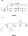
- FIG. 2is a diagram illustrating a synchronization packet, consistent with some embodiments.
- Synchronization packet 200includes a packet header 202 and a packet body 204.
- Packet body 204includes a synchronization header 206 and attributes 108 to be synchronized in the synchronization payload 208.
- Each of the attributes 108 to be synchronizedmay include an attribute header 210 and an attribute payload 212.
- synchronization header 206may include a synchronization state (such as reset, start, continue, and end), a serial number associated with a group of attributes being published in the same publish event, and a packet count.
- Attribute header 210may include attribute tag 110, a timestamp of the last modification of attribute, and the length of the attribute payload 212 following attribute header 210.
- attribute header 210may also include an offset allowing the attribute payload to be split and transferred across multiple synchronization packets 200.
- a database of a publishing nodesuch as database 104 shown in FIG. 1
- the database of the publishing nodecan then arrange the attributes 108 into synchronization packets 200, in which a first packet will be indicated as "start” in synchronization header 206, subsequent packets will be indicated as “continue” in synchronization header 206, and the final packet will be indicated as "end” in synchronization header 206.
- a first packetwill be indicated as "start” in synchronization header 206
- subsequent packetswill be indicated as “continue” in synchronization header 206
- the final packetwill be indicated as "end” in synchronization header 206.
- if only two synchronization packets are arrangedthey will respectively be indicated as "start” and "end” in synchronization header 206.
- synchronization packet 200If only one synchronization packet 200 is arranged, it will be indicated as "end" in synchronization header 206.
- the synchronization packets 200are then transmitted by the database of the publishing node and received by the database of the subscribing node.
- attributes 108will be unpacked and written into the database.
- the database of the subscribing nodeprocesses a synchronization header 206 having an "end" designation, an acknowledgement message to the publishing node. Then, consistent with some embodiments, the subscribing node will act as a publishing node and publish attributes to its subscribed nodes 102.
- FIG. 3is a diagram illustrating a system in which multiple synchronization database instances are executing on nodes 102, consistent with some embodiments.
- each node 102is capable of executing multiple synchronization database instances.
- node 102-1is executing both (i) a server instance of a synchronization database 104 for publishing attributes to subscribing node 102-2 and associated database 106, and (ii) a client instance of a synchronization database instance 302 that subscribes to node 304 and its associated database 306.
- database 302is subscribed to attributes 308 in database 306, as noted in subscriber list 316, and database 302 will receive these attributes 308 when they are written or otherwise modified in database 306.
- database 104will publish written or otherwise modified attributes 108 to database 106 of subscribed node 102-2 and to additional coupled nodes 310-1 to 310-N, if so subscribed.
- Each node 102, 304, and 310is capable of running multiple instances of a synchronization database such that it can be both a subscribing node and a publishing node. And, consistent with some embodiments, one or more of the databases executing at a single node may be double buffered, as described above.
- a single nodemay be both a publishing and subscribing node, and these publishing and subscribing functions may be carried out with either a single attribute data synchronization database or with multiple attribute data synchronization databases.
- a single nodemay publish a first set of attributes to a corresponding first set of one or more subscribing nodes and a second set of attributes to a corresponding second set of one or more subscribing nodes.
- a single nodemay subscribe to a first set of attributes from a first publishing node and a second set of attributes from a second publishing node.
- the various features discussed above, such as heartbeat signalsmay be features of one or more of the various synchronization databases.
- a set of interconnected nodesmay perform attribute updates not just in a single "downstream" direction but in both directions.
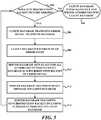
- FIGS. 4A and 4Bare flowcharts illustrating a method of synchronizing attributes between a publishing node and a subscribing node, consistent with some embodiments.
- FIG. 4Aillustrates the actions performed by database 104 of node 102-1
- FIG. 4Billustrates the actions performed by database 106 of node 102-2.
- the method shown in FIGS. 4A and 4Bwill be described with reference to FIGS. 1-3 .
- the method shown in FIGS. 4A and 4Bmay be included in instructions contained in a memory of a robotic system or a memory associated with a node 102 and may be executed by one or more processors included in the robotic system or associated with a node 102.
- publishing node 102-1 having a server instance of a synchronization database 104periodically transmits an advertise message (401), and a subscribing node 102, such as node 102-2 having a client instance of a synchronization database 106 executing thereon, periodically transmits a discover message (402).
- database 104 and a client database 102may respectively transmit an advertise message and a discover message upon an initial connection between publishing node 102-1 having database 104 and subscribing node 102 having database 106 or when database 104 and 106 start up.
- the advertisement messagemay include information about attributes 108 that are stored in database 104.
- the discover messagemay indicate the attributes 108 that database 106 of subscribing node 102-2 requires.
- database 104 of node 102-1receives the discover message (403) from node 102-2, it will transmit a discover reply message (404) back to the subscribing node.
- the subscribing node 102-2receives an advertise message (405) from the publishing node or receives the discover reply message (406) from the publishing node, a server discovered callback (407) will be initiated by database 106 of subscribing node 102-2, informing the subscribing node that publishing node 102-1 having database 104 has been discovered. Subscribing node 102-2 will then transmit an add subscriber message to publishing node 102-1 (408).
- the add subscriber messagemay indicate which attributes subscribing node 102-2 wants to subscribe to.
- database 104 of publishing node 102-1will add the node 102-2 as a subscriber (409) and it to subscriber list 116.
- Adding subscribing node 102-2 as a subscriberwill also initiate a subscriber added callback (410) that informs a publishing node 102-1 that a subscriber has been added.
- database 104will set flag 114 for all subscribed attributes (411) and wait for a sync-reply message from subscribing node 102-2 (412). While database 104 waits for the sync-reply message from subscribing node 102-2, modifications to attributes 108 are aggregated in database 104 until the sync-reply message is received.
- database 106there is a built-in throttling of the information transmitted to database 106 of subscribing node 102-2, such that database 106 only receives an amount of information that it can accept.
- subscribing node 102-2after subscribing node 102-2 transmits a sync-reply message (413), it will wait for a synchronization packet to be transmitted by publishing node 102-1 (414).
- publishing node 102-1receives a sync-reply message from subscribing database 102-2
- database 104 of publishing node 102-1will determine if any attribute subscribed to subscribing node 102-2 has flag 114 set (415). If database 104 of publishing node 102-1 has just added client database 106 as a subscriber to one or more attributes, flag 114 for all attributes 108 will be set.
- flag 114 for attributes 108will be set when an attribute 108 is modified, which database 104 will process when a modify-attribute call is received from the publishing application (416). If no attribute 108 has flag 114 set, database 104 will enter an idle state and wait for a publish call from the server application (417). If database 104 determines that there are still attributes 108 having flag 114 set and/or when database 104 receives a publish call (418), database 104 of publishing node 102-1 publishes one or more synchronization packets 200 that includes attributes 108 having flag 114 set (419), clears flag 114 for all published attributes 108 (420), and then proceeds to wait for a sync-reply signal from subscribing node 102-2 (412).
- database 106 of subscribing node 102-2When database 106 of subscribing node 102-2 receives the one or more synchronization packets 200 from publishing node 102-1 (421), database 106 updates attributes 108 stored therein (422) and checks to see, for every synchronization packet received, if the received packet is the final packet indicated as "end" in synchronization header 206 (423). If database 106 of subscribing node 102-2 determines that the received synchronization packet 200 is not the final packet, it will continue to wait for additional synchronization packets 200 from database 104 of publishing node 102-1 (414).
- database 106 of subscribing node 102-2will initiate a client update callback (424), which will send a sync-reply message to publishing node 102-1 (413) and republish the updated attributes 108 to any downstream subscribers (425), such as nodes 102- 3 to 102-N.
- client databasemay perform error detection on received synchronization packets 200. An example of an error detection method is described with respect to FIG. 5 , below.
- FIG. 5is a flowchart illustrating an error detection method consistent with some embodiments. For the purposes of illustration, the method shown in FIG. 5 will be described with reference to FIGS. 1-3 .
- the method shown in FIG. 5may be included in instructions contained in a memory of a robotic system or associated with a node 102 and may be executed by one or more processors included in the robotic system or associated with a node 102.
- a subscribing nodesuch as node 102-2, will scan synchronization packet 200 for errors (502). If no errors are found in synchronization packet 200, database 106 of subscribing node 102-2 will process synchronization packet 200 normally such that the attributes are unpacked and written into database 106 (504). If an error is detected, an error signal will be transmitted by subscribing node 102-2 to publishing node 102-1 (506).
- Subscribing node 102-2will then enter into an error state wherein any further received synchronization packets 200 having a synchronization header 206 with a "start”, “continue”, or "end” indication will be discarded (508).
- database 104will set flag 114 for all attributes to which subscribing node 102-2 is subscribed (510).
- Publishing node 102-1then transmits a reset message, which may be a synchronization packet 200 having a synchronization header 206 with a "reset” indication, to subscribing node 102-2 (512).
- the reset messagemay not include any payload and will serve to reset the expected sequence of attributes received by database 106 of subscribing node 102-2.
- Publishing node 102-1then transmits synchronization packet 200 including flagged attributes to subscribing node 102-2 (514), and database 106 of subscribing node 102-2 will again scan synchronization packet 200 for errors (502). Consistent with some embodiments, if another error is found, another error signal will be sent and steps 506-514 will be performed again.
- database 104 of publishing node 102-1may include a counter that counts the number of attempts to successfully transmit synchronization packet 200 to subscribing node 102-1 and will abort the transmission if the counter reaches a predetermined number. Database 104 may then log that an error has occurred and generate a timeout allowing database 104 to take any action for safety purposes or to correct the error on a timeout callback. The counter may be reset when publishing node 102-1 receives an acknowledgement message from subscribing node 102-2 indicating a successful transmission.
- Embodiments as described in FIGS 1-5may be used in robotic systems to synchronize nodes of the robotic system with minimal system traffic and lag. Some embodiments may also be used in robot-assisted surgical systems to synchronize nodes of a robot-assisted surgical system in order to synchronize nodes with minimal system traffic and delay, making the system reliable and providing a near-real-time response to a surgeon's actions (e.g., a response in which the surgeon perceives no delay between commanding a system component to move or function and the actual motion or function). Examples of the use of system 100 are described in FIGS. 6-9 , below.
- FIG. 6is an example of system 100 being used in a robotic system.
- robotic system 600includes a first unit controller 602 coupled to a second unit controller 604.
- Each of the unit controllers 602 and 604are respectively coupled to a subsystem supervisor 606 and 608 as shown.
- Subsystem supervisor 606includes a dispatcher 610 coupled to a plurality of mechanical manipulators 612-1 to 612-N.
- Subsystem supervisor 608includes a dispatcher 614 coupled to a plurality of mechanical manipulators 616-1 to 616-N.
- each unit controller, dispatcher, and manipulatormay correspond to a node 102-1 to 102-N described above with respect to FIGS. 1 and 3 .
- each manipulatormay correspond to a different mechanical part (e.g., a different link in a serial kinematic chain, a different actuator, a different sensor, a different system subgroup, etc.) of robotic system 600.
- dispatcher 610acts as a subscribing node for each manipulator 612-1 to 612-N and for unit controller 602. That is, dispatcher 610 executes a client instance of a synchronization database for each manipulator 612-1 to 612-N and unit controller 602 so that dispatcher 610 subscribes to certain attributes available from unit controller 602 and subscribes to certain attributes available from each manipulator 612-1 to 612-N, all of which act as a publishing node to dispatcher 610. Dispatcher 610 may then republish attributes from unit controller 602 to manipulators 612-1 to 612-N and republish attributes from manipulators 612-1 to 612-N to unit controller 602.
- dispatcher 610may act as a publisher/subscriber between other manipulators 612-1 to 612-N so that dispatcher 610 may synchronize attributes between manipulators 612-1 to 612-N.
- manipulators 612-1 to 612-Nmay be physically removed and added to system 600, or "hot-swapped", because when a new manipulator 612 is added, it will be capable of executing a client instance of a synchronization database to act as a subscribing node, and it will immediately subscribe to desired attributes, which will then be published to the added manipulator by dispatcher 610, thus providing the new manipulator with the latest states of the desired attributes.
- Dispatcher 614provides similar functionality with respect to unit controller 604 and manipulators 616-1 to 616-N.
- FIG. 7is another example of system 100 used in a robotic system, consistent with some embodiments.
- system 700includes a supervisor node 702 coupled to one or more synchronization databases 704.
- supervisor node 702transmits states of supervisor node 702 to one or more synchronization databases 704, which publish the received states to user interface (UI) node 706 and video subsystem node 708.
- UIuser interface
- supervisor node 702executes a server instance of a synchronization database and acts as a publishing node, to which the one or more synchronization databases 704 execute a client instance of a synchronization database and acts as a subscribing node to supervisor node 702.
- One or more synchronization databases 704then republish attributes and states of supervisor node 702 to UI node 706 and video subsystem node 708.
- UI node 706may then interpret states of supervisor node 702 into actions 710 that are performed by one or more controllers 712 coupled to UI node 706.
- video subsystem node 708may interpret states of supervisor node 702 into commands for displaying video.
- supervisor node 702is also coupled to video subsystem node 708 to receive user interface events 714 from video subsystem node 708.
- user interface events 714may cause a change in a state of supervisor node 702, and the changed state will be flagged and then published to one or more synchronization databases 704 in accordance with embodiments described above.
- Video subsystem node 708may additionally drive multiple displays, where the content for each display is determined by the state propagated via the synchronization database.
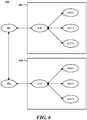
- FIG. 8is an example of system 100 used in a robotic system 800, consistent with some embodiments.
- Robotic system 800includes a plurality of nodes coupled together in a tree structure.
- Robotic system 800includes a display controller node 802 that is coupled to a video pipeline node 804 and additional controller nodes 806.
- Video pipeline node 804is coupled to further additional controller nodes 808-1 to 808-N.
- robot system 800synchronizes data across the nodes using a system similar to system 100.
- video pipeline node 804executes a client instance of a synchronization database and subscribes to further additional controller nodes 808-1 - 808-N, each of which are executing a server instance of a synchronization database and publishing attributes.
- display controller node 802executes a client instance of a synchronization database and subscribes to video pipeline node 804 and additional controller nodes 806-1 to 806-N, each of which are executing a server instance of a synchronization database and publishing attributes. Consequently, any attribute changes in further additional controller nodes 808 will be published to video processor node 804, and any attribute changes in video processor node 804 (including those received from further additional controller nodes 808) and additional controller nodes 806-1 to 806-N will be published to display controller node 802.
- Display controller node 802in turn executes a "root" server database to re-publish one or more important "globally visible” states it has collected from subordinate nodes 804, 806-1 to 806-N (and 808-1 to 808-N, via 804).
- Subordinate nodes 804, and 806-1 to 806-Nsubscribe to this root database; node 808-1 to 808-N subscribes to node 804 for the root database content.
- any newly added node to the tree structurewill be able to execute a client instance of a synchronization database, subscribe to desired attributes, and be published the most recent state of the desired attributes, as described in previous embodiments.
- FIG. 9is an example of system 100 used in a robot-assisted surgical system 900, consistent with some embodiments.
- system 900includes a patient cart 902 coupled to a core system 904, which is in turn coupled to a surgeon console 906.
- system 900may correspond to a da Vinci® Surgical System commercialized by Intuitive Surgical, Inc. of Sunnyvale, California, such that patient cart 902 includes slave manipulator controlled surgical instruments (including a camera instrument), surgeon console 906 includes master controls for the slave manipulators, and core system 904 includes camera and vision system processing components in addition to other system data processing components.
- each of patient cart 902, core system 904, and surgeon console 906may be capable of executing one or more synchronization databases consistent with embodiments disclosed above, and may be referred to as nodes of system 900 Further, each of the nodes of system 900 may contain additional nodes.
- patient cart 902may include one or more processors that are each capable of executing a client instance of a synchronization database, and these one or more processors may be referred to as node 908 that subscribes to attributes published by individual nodes within patient cart 902, such as setup joint 910 and manipulator 912, each of which include associated processors that are executing a server instance of a synchronization database.
- Node 908executing a client instance of a synchronization database, receives the published attributes from setup joint 910 and manipulator 912 and stores these attributes in the client instance of a synchronization database. These attributes may then be published by node 908 to core system 904, with node 908 executing a server instance of a synchronization database and core system 904 executing a client instance of a synchronization database. Similarly, node 908 may execute a client instance of a synchronization database for subscribing to attributes published from a server instance on core 904. A similar arrangement may be provided between core 904 and surgeon console 906 so that attributes may be synchronized across system 900.
- patient cart 902can operate in a stand-alone environment in which node 908, executing a client instance of a synchronization database, receives the published attributes from robotic manipulator setup arm joint 910 and from manipulator clutch 912, and then stores these attributes in a client instance of a synchronization database.
- node 908Upon reconnection with system 900, node 908 will publish its stored values to core 904, and then core 904 will publish its stored values to node 908 so that the data attributes throughout system 900 will be synchronized.
- the synchronization of systemwill operate similarly for the disconnection and subsequent reconnection of surgeon console 906 or any other system component for which an attribute database synchronization function is executed.
- various embodiments provided by the present disclosuremay be implemented using hardware, software, or combinations of hardware and software.
- the various hardware components and/or software components set forth hereinmay be combined into composite components comprising software, hardware, and/or both without departing from the present disclosure.
- the various hardware components and/or software components set forth hereinmay be separated into sub-components comprising software, hardware, or both without departing from the scope of the present disclosure.
- software componentsmay be implemented as hardware components and vice versa.
- Softwarein accordance with the present disclosure, such as program code and/or data, may be stored on one or more computer readable mediums. It is also contemplated that software identified herein may be implemented using one or more general purpose or specific purpose computers and/or computer systems, networked and/or otherwise. Where applicable, the ordering of various steps described herein may be changed, combined into composite steps, and/or separated into sub-steps to provide features described herein.
- Embodiments as disclosed hereinmay provide systems and methods for synchronizing nodes in a system with minimal system traffic and minimal collisions and interruption. Embodiments as disclosed herein may also provide systems and methods for synchronizing nodes in a system that allow a node to easily connect, disconnect, and reconnect to the system and be synchronized with minimal lag. Further, embodiments as disclosed herein may also provide systems and methods for synchronizing nodes in a system that allows a display at one node to me duplicated at another node with minimal lag.
- the examples provided aboveare exemplary only and are not intended to be limiting. One skilled in the art may readily devise other systems consistent with the disclosed embodiments which are intended to be within the scope of this disclosure. As such, the application is limited only by the following claims.
Landscapes
- Engineering & Computer Science (AREA)
- Theoretical Computer Science (AREA)
- Databases & Information Systems (AREA)
- Physics & Mathematics (AREA)
- General Engineering & Computer Science (AREA)
- General Physics & Mathematics (AREA)
- Health & Medical Sciences (AREA)
- Data Mining & Analysis (AREA)
- Life Sciences & Earth Sciences (AREA)
- Surgery (AREA)
- Robotics (AREA)
- Software Systems (AREA)
- Computing Systems (AREA)
- General Health & Medical Sciences (AREA)
- Public Health (AREA)
- Veterinary Medicine (AREA)
- Biomedical Technology (AREA)
- Heart & Thoracic Surgery (AREA)
- Medical Informatics (AREA)
- Animal Behavior & Ethology (AREA)
- Molecular Biology (AREA)
- Nuclear Medicine, Radiotherapy & Molecular Imaging (AREA)
- Multimedia (AREA)
- Computer Security & Cryptography (AREA)
- Information Retrieval, Db Structures And Fs Structures Therefor (AREA)
- Information Transfer Between Computers (AREA)
- Small-Scale Networks (AREA)
- Manipulator (AREA)
- Computer And Data Communications (AREA)
Description
- This application claims priority to
U.S. Provisional Patent Application No. 61/765,559, filed on February 15, 2013 U.S. Nonprovisional Patent Application No. 14/181,499, filed on February 14, 2014 - The present disclosure is related to systems and methods for synchronizing nodes of a robotic system. In particular, the present disclosure is related to synchronization databases that can be executed at each node of the robotic system, the synchronization databases allowing for the subscription and publishing of updated attributes between the nodes of the robotic system.
- Certain applications have high bandwidth requirements and strict synchronization, latency, and reliability requirements for communications. Robot-assisted surgery, for example, requires low-latency to transmit control and feedback signals in real time. The synchronization and latency requirements of such applications are strict, because ideally there should be as little lag as possible between the movements of a surgeon controlling a master input and the movements of the robot slaved to the master.
- Complex systems, including robot-assisted surgery systems, include many components, referred to generally herein as "nodes", that work together within the system and therefore need to be able to remain synchronized. For each of these coupled nodes, the synchronization is often performed by a first node sending data requests to a second node, to which the second node will respond to the request by providing the requested data to the first node. In some instances, a first node will check for the presence of the second node and a third node, and if the second and third node are found to be present, the first node will then push data to the second and third nodes. If the second or third nodes are disconnected from the first node and then reconnected, the first node may not be notified that the second or third node was disconnected, and as a result the reconnected node may be missing data that the first node sent during the disconnection. Furthermore, when a new node is coupled to the first node, the first node may not check for the presence of the new node and, thus, not provide any data to the new node so that data at the new node is not synchronized with the first node's data. Ultimately, the need for the system to continually check for the presence of nodes and then send data to each of the nodes to remain synchronized may create unnecessary system traffic that can slow down the system or overflow message queues.
- What is needed are systems and methods that permit the automatic synchronization of nodes in a system with minimal system traffic and that allow for the rapid synchronization of new nodes to the system.
WO99/10788 - The present invention provides a publishing node of a robotic system, the publishing node comprising: one or more processors; and a first synchronization database, the first synchronization database comprising: a plurality of attributes, each of the attributes including data and a tag identifying the attribute; a flag associated with each of the attributes; and a subscriber list; wherein the publishing node is configured to set a corresponding flag associated with the attributes when the attributes are written in the first synchronization database or when the data included in the attributes is modified; aggregate modifications to the attributes until a synchronization reply signal is received from a subscriber node; and publish the flagged attributes to the subscriber node after receiving the synchronization reply signal; wherein the flag includes a bit for each subscriber node in the subscriber list.
- The present invention also provides a method for synchronizing data across nodes of a robotic system, comprising: transmitting, from a publishing node, an advertising message advertising a plurality of attributes stored in a server instance of a synchronization database executing on the publishing node; receiving, by a subscribing node coupled to the publishing node, the advertising message; transmitting, by the subscribing node, a subscription message indicating one or more of the plurality of attributes stored in the server instance of the synchronization database executing on the publishing node that the one subscribing node wants to subscribe to; adding, by the publishing node, the subscribing node to a subscription list maintained in the server instance of the synchronization database executing on the publishing node; setting, by the publishing node, a flag for each of the one or more attributes; transmitting a synchronization reply signal from the subscribing node to the publishing node; aggregating modifications to the plurality of attributes in the synchronization database executing on the publishing node until the synchronization reply signal is received; transmitting, by the publishing node, a synchronization packet including each of the flagged attributes to the subscribing node after receiving the synchronization reply signal; and clearing the flag for each of the transmitted attributes; wherein the flag (114) includes a bit for each subscriber node in the subscriber list.
- Further consistent with some examples, there is also provided a non-transitory computer-readable medium having instructions for execution by one or more processors of a robotic system, when executed, cause the one or more processors to perform a method for synchronizing nodes of the robotic system. The method includes transmitting, from a publishing node, an advertising message advertising attributes stored in a server instance of a synchronization database executing on the publishing node, receiving, by a subscribing node coupled to the publishing node, the advertising message, and transmitting a subscription message from the subscribing node to the publishing node, the subscription message indicating the attributes stored in the server instance of a synchronization database executing on the publishing node that the at least one subscribing node wants to subscribe to. The method also includes adding the subscribing node to a subscription list maintained in the server instance of a synchronization database executing on the publishing node, setting a flag for each of the subscribed attributes in the server instance of a synchronization database executing on the publishing node, transmitting a synchronization packet from the publishing node to the subscribing node, the synchronization packet including each of the flagged attributes, and clearing the flag for each of the transmitted attributes in the server instance of a synchronization database executing on the publishing node.
- These and other embodiments will be described in further detail below with respect to the following figures.
FIG. 1 is a diagram illustrating a system for synchronizing nodes in a system using instances of a synchronization database, consistent with some embodiments.FIG. 2 is a diagram illustrating a synchronization packet, consistent with some embodiments.FIG. 3 is a diagram illustrating a system in which multiple synchronization database instances are executing on nodes, consistent with some embodiments.FIGS. 4A and4B are flowcharts illustrating a method of synchronizing attributes between a server database and a client database, consistent with some embodiments.FIG. 5 is a flowchart illustrating an error detection method consistent with some embodiments.FIG. 6 is an example of the system ofFIG. 1 being used in a robotic system, consistent with some embodiments.FIG. 7 is another example of the system ofFIG. 1 being used in a robotic system, consistent with some embodiments.FIG. 8 is another example of the system ofFIG. 1 being used in a robotic system, consistent with some embodiments.FIG. 9 is an example of the system ofFIG. 1 being used in a robot-assisted surgical system, consistent with some embodiments.- In the drawings, elements having the same designation have the same or similar functions.
- In the following description specific details are set forth describing certain embodiments. It will be apparent, however, to one skilled in the art that the disclosed embodiments may be practiced without some or all of these specific details. The specific embodiments presented are meant to be illustrative, but not limiting. One skilled in the art may realize other material that, although not specifically described herein, is within the scope of this disclosure. Various mechanical, compositional, structural, electrical, and operational changes may be made without departing from the scope of this description and the claims. In some instances, well-known circuits, structures, and techniques have not been shown in detail in order not to obscure the invention. In addition, the singular forms "a", "an", and "the" are intended to include the plural forms as well, unless the context indicates otherwise. And, the terms "comprises", "comprising", "includes", and the like specify the presence of stated features, steps, operations, elements, and/or components but do not preclude the presence or addition of one or more other features, steps, operations, elements, components, and/or groups. Components described as coupled may be electrically or mechanically directly coupled, or they may be indirectly coupled via one or more intermediate components.
FIG. 1 is a diagram illustrating asystem 100 for synchronizing nodes in a system using instances of a synchronization database, consistent with some embodiments. As shown inFIG. 1 ,system 100 includes a plurality of interconnected nodes 102-1 to 102-N (referred to collectively as "nodes 102"). Consistent with some embodiments, eachnode 102 may be a device, a component of a robotic system, one or more processors, individual tasks that are being performed by the one or more processors.Nodes 102 may include any appropriate combination of hardware and/or software having one or more processors and capable of reading instructions stored on a non-transitory machine-readable medium for execution by the one or more processors. Such instructions may include instructions for creating one or more instances of a synchronization database, as described herein.- Returning to
FIG. 1 ,nodes 102 include a first node 102-1 coupled to a second node 102-2 which, in turn, is coupled to a plurality of nodes 102-3 to 102-N. Although not shown inFIG. 1 , node 102-1 may be directly coupled to additional nodes in a way similar to the connection with node 102-2. Consistent with some embodiments, a memory (not shown) is associated with eachnode 102. Further, one or more processors can also be associated with eachnode 102. Instructions for creating an instance of a synchronization database may be stored in the memory, and the one or more processors can execute these instructions to create one or more instances of a synchronization database at eachnode 102. Consistent with some embodiments, the synchronization database is a software container object that (i) stores data attributes, such as states or events, (ii) supports the aggregation of data changes on one node, referred to as a publishing node, and (iii) supports the publication of that changed data to one or more subscriber nodes.. The synchronization database may accomplish this through the execution of one or more synchronization applications that are executed at each node to perform the functions necessary to subscribe to a publishing node and receive data changes or publish data changes to one or more subscribing nodes. The synchronization applications may be referred to as a publishing application for a publishing node and a subscribing application for a subscribing node. - As shown in
FIG. 1 , node 102-1 is executing a server instance of asynchronization database 104, and acts as a publishing node and node 102-2 is executing a client instance of asynchronization database 106, and acts as a subscribing node. A synchronization database, both server instances and client instances, may store a set of data-vectors, referred to asattributes 108, a list of subscribingnodes 116, and an additional state (not shown) that may be used to manage synchronization.Attributes 108 may refer to data that includes states or events insystem 100, and may further include counters and time stamps.Attributes 108 may also refer to data that are behavioral elements used to describe behaviors ofsystem 100. Consistent with some embodiments, attributes 108 may refer to user interface (UI) states or events that may be visual representations of states or events occurring on one node which can be published to additional nodes to update the additional nodes of the events and/or replicate the visual representation of these states or events at the additional nodes.Attributes 108 may also be stored in one or more databases, such as adatabase 104 associated with node 102-1 anddatabase 106 associated with node 102-2 shown inFIG. 1 . - As shown in
FIG. 1 , attributes 108 include atag 110,data 112, and an associatedflag 114 that can be set or cleared. Althoughdatabase 104 associated with node 102-1 anddatabase 106 associated with node 102-2 are shown as having only three or four attributes, the number of attributes is only limited by the memory allocated for the synchronization database instance on eachnode 102. Consistent with some embodiments, attributes 108 stored indatabase 104 ordatabase 106 are sent to a requesting node when the node associated withdatabase 104 ordatabase 106 receives a query from the requesting node. - Each
attribute 108 stored in a synchronization database is uniquely identified by atag 110. Consistent with some embodiments,tag 110 may be a 32-bit tag and may support efficient database operation by using a hash-table lookup function.Flag 114 indicates whetherattribute 108 requires publishing to synchronizeattribute 108 with subscribingclient database 106. Whenattribute 108 is written todatabase 104 or otherwise modified indatabase 104 such that thecorresponding attribute 108 stored bydatabase 106 may be different,flag 114 is set. Node 102-1 may modify one ormore attributes 108, settingflag 114 for each modifiedattribute 108. Node 102-1 may then call a "publish" method on its associateddatabase 104, to publish allattributes 108 stored indatabase 104 withflag 114 set to subscribingnodes 102, such as node 102-2. After anattribute 108 is published,flag 114 is cleared indatabase 104.Flag 114 may be a field that includes a bit for each subscribingnode 102. - As shown in
FIG. 1 ,database 104 also includes asubscriber list 116, which is a listing ofnodes 102 and their associated databases that have subscribed to one ormore attributes 108 stored indatabase 104. Consistent with some embodiments,database 104 advertises its stored attributes 108. In such embodiments,database 104 may periodically transmit a signal to all couplednodes 102 indicating theattributes 108 and data that it is storing so that other nodes, such as node 102-2, can determine if it should fully or partially subscribe to one or more of theattributes 108 stored indatabase 104. For example,database 104 may transmit an advertise message upon an initial connection with subscribingnode 102 or whendatabase 104 starts up. At the same time,database 106 periodically transmits a discover message to attempt to identify a node having an associated database that stores data thatdatabase 106 requires. For example,database 106 may transmit a discover message upon an initial connection with publishing node 102-1 havingdatabase 104 or whendatabase 106 starts up. Whendatabase 104 receives a discover message ordatabase 106 receives an advertise signal,database 104 anddatabase 106 will establish a link. Upon receiving a discover message,database 104 will transmit a discover reply signal todatabase 106. Upon receiving an advertise signal or a discover reply signal,database 106 will send a subscribe message todatabase 104, establishing the link of the two nodes and the subscription ofdatabase 106 associated with node 102-2 to one ormore attributes 108 stored indatabase 104 associated with node 102-1. Node 102-2 is then added tosubscriber list 116. - Node 102-2 and it associated
database 106 may subscribe to allattributes 108 stored indatabase 104 or may only subscribe to certain attributes. Eachnode 102 may have a unique identifier stored insubscriber list 116 for uniquely identifying the subscribed node. When anode 102 subscribes toattributes 108 stored indatabase 104, the node is allocated aflag 114 for each subscribedattribute 108 such that when the subscribed attribute is modified,flag 114 will be set. When anode 102 initially subscribes to aserver database 104, all attributes 108 to which it is subscribed will haveflag 114 set. The subscribing node, such as node 102-2 and its associateddatabase 106, may then send a reply message todatabase 104 indicating that it is ready to receive allattributes 108 havingflag 114 set. Whiledatabase 104 waits for the reply message from the subscribing node, such as node 102-2 and its associateddatabase 106,database 104 will aggregate any further changes or modifications to subscribedattributes 108 and setflag 114 accordingly. After receiving the reply message,database 104 will then publish theattributes having flag 114 set and thenclear flag 114. After theattributes 108 are received they are checked for errors, and if there are no errors, the database of the subscribing node transmits an acknowledgment message todatabase 104. Any subscribed attributes 108 that are modified whiledatabase 104 waits for the acknowledgment message will be published to the database of the subscribing node after receiving the acknowledgement message. If the database of the receiving node determines that the received attributes 108 include errors, the database will enter an error state and request thatdatabase 104 retransmit the subscribed attributes. The method of publishing attributes 108 is discussed further with respect toFIG. 4 , below. - Just as node 102-2 executes a client instance of a synchronization database to subscribe to
attributes 108 stored indatabase 104 at node 102-1, nodes 102-3 to 102-N may also execute a client instance of a synchronization database to subscribe to attributes in the synchronization database at node 102-2. - Consistent with some embodiments, a synchronization database instance may be double-buffered so that it may act as both a client and a server to republish received attributes to downstream nodes. For example, node 102-2 may execute a client instance of a synchronization database to subscribe to attributes stored in
database 104 of node 102-1. Attributes (with an updated state) received fromdatabase 104, possibly spanning multiple synchronization packets (described below with reference toFig. 2 ), are stored in a first inactive/"background" buffer at node 102-2. At the same time, the same attributes (with a current state) stored in a second active/"foreground" buffer at node 102-2 can be published to subscribing nodes 102-3 to 102-N. When the synchronization update between nodes 102-1 and 102-2 is complete, the background and foreground buffers are swapped so that the new foreground buffer has the most recent attributes received from node 102-1. Then, theattributes 108 held at node 102-2 in the updated foreground buffer, are used to update downstream nodes 102-3 to 102-N. Node 102-2 republishes theattributes 108, received from node 102-1 into the background buffer and then swapped into the foreground buffer, to any nodes 102-3 to 102-N that have subscribed to receive the attributes from node 102-2. In the example described, it is not necessary for node 102-2 to execute a server instance to publishattributes 108 received from node 102-1 to nodes 102-3 to 102-N, as the client instance is capable of republishingattributes 108 as described. However, node 102-2 is capable of executing both a server instance and a client instance of a synchronization database, as described below with respect toFIG. 3 . - Moreover, although node 102-2 is described as being double-buffered to republish received attributes to downstream nodes, any
node 102 that subscribes to another node may benefit from being double-buffered, even if the node is not republishing the received attributes to downstream nodes. For example, a subscribing node, such as node 102-3 may receive modified attributes from a publishing node, such as 102-2, in synchronization packets that will be described further with respect toFIG. 2 , below. These synchronization packets will be received by node 102-3 and be stored in the background buffer as they are received. Once node 102-3 has received the synchronization packets for a particular synchronization operation, the background buffer will be swapped with the foreground buffer, giving node 102-3 an atomic view of the aggregated transaction, and allowing node 102-3 to receive further synchronization packets to be stored in the just-swapped foreground buffer, which now acts as the background buffer. - Consistent with some embodiments, publishing nodes such as 102-1 having
database 104, may transmit a heartbeat signal to thosenodes 102 that subscribe to itsattributes 108, such as node 102-2 havingdatabase 106. The heartbeat signal may be a synchronization update signal having synchronization packets with no attributes. Consistent with some embodiments, the heartbeat signal may be transmitted periodically from publishing node 102-1 after an attribute synchronization, and the periodic transmission is reset after each attribute synchronization. When receiving the heartbeat signal,database 106 will view the heartbeat signal as a synchronization signal and send a reply message just as if the signal included updated attributes. Subscribing nodes, such as node 102-2, havingclient database 106 will periodically receive this heartbeat signal and therefore be aware thatdatabase 104 is online anddatabase 106 will receive updated attributes to which it has subscribed. If a subscribing node stops receiving the periodic heartbeat signal, it will be aware thatdatabase 104 of node 102-1 is offline and not providing updated attributes.Database 106 may then begin to analyze advertising messages transmitted from publishing nodes, may begin to issue discover messages to server nodes, and may subscribe to the publishing nodes having desired attributes. In some embodiments, for example after a communication break between publishing and subscribing nodes,database 106 of node 102-2 may re-subscribe todatabase 104 of node 102-1 to receive desired attributes. - If a database of any subscribing
node 102, goes offline for a predetermined period of time sufficient for a publishing node to consider the subscribing node and/or its associated database as being "dead" due to the lack of received reply messages, the database of the publishing node may remove the subscribing node and its associated database from its subscriber list. Once the subscribing node, comes back online, it may re-subscribe to one or more attributes stored in the database of the publishing node in the same way it did previously. That is, there-subscribing node 102, will receive the advertisement message transmitted from the publishing node indicating theattributes 108 and data available from its associated database, or send a discover message indicating attributes that it wants to subscribe to, and it will then subscribe messages to one ormore attributes 108 stored in the database of the publishing node. The database of the publishing node will then add the re-subscribing node back to itssubscriber list 116, and will set theflag 114 for each of the indicated attributes 108. Upon receipt of an initial "sync-reply" issued from the database of the re-subscribing node the database of the publishing node will publish the attributes withflag 114 set. The database of there-subscribed node 102 will then receive any future modifications to its subscribed attributes 108. FIG. 2 is a diagram illustrating a synchronization packet, consistent with some embodiments. When a database of a publishing node publishesattributes 108 to subscribingnodes 102, theattributes 108 are transmitted assynchronization packets 200.Synchronization packet 200 includes apacket header 202 and apacket body 204.Packet body 204 includes asynchronization header 206 and attributes 108 to be synchronized in thesynchronization payload 208. Each of theattributes 108 to be synchronized may include anattribute header 210 and anattribute payload 212. Consistent with some embodiments,synchronization header 206 may include a synchronization state (such as reset, start, continue, and end), a serial number associated with a group of attributes being published in the same publish event, and a packet count.Attribute header 210 may includeattribute tag 110, a timestamp of the last modification of attribute, and the length of theattribute payload 212 followingattribute header 210. Consistent with some embodiments,attribute header 210 may also include an offset allowing the attribute payload to be split and transferred acrossmultiple synchronization packets 200.- Consistent with some embodiments, a database of a publishing node, such as
database 104 shown inFIG. 1 , will identifyattributes 108 havingflag 114 set and prepare these attributes for publishing to databases of subscribing nodes, such asdatabase 106 of node 102-2. The database of the publishing node can then arrange theattributes 108 intosynchronization packets 200, in which a first packet will be indicated as "start" insynchronization header 206, subsequent packets will be indicated as "continue" insynchronization header 206, and the final packet will be indicated as "end" insynchronization header 206. Consistent with some embodiments, if only two synchronization packets are arranged, they will respectively be indicated as "start" and "end" insynchronization header 206. If only onesynchronization packet 200 is arranged, it will be indicated as "end" insynchronization header 206. Once thesynchronization packets 200 are structured, they are then transmitted by the database of the publishing node and received by the database of the subscribing node. As eachsynchronization packet 200 is received by the database of the subscribing node, attributes 108 will be unpacked and written into the database. Once the database of the subscribing node processes asynchronization header 206 having an "end" designation, an acknowledgement message to the publishing node. Then, consistent with some embodiments, the subscribing node will act as a publishing node and publish attributes to its subscribednodes 102. FIG. 3 is a diagram illustrating a system in which multiple synchronization database instances are executing onnodes 102, consistent with some embodiments. As shown inFIG. 3 , eachnode 102 is capable of executing multiple synchronization database instances. For example, as shown inFIG. 3 , node 102-1 is executing both (i) a server instance of asynchronization database 104 for publishing attributes to subscribing node 102-2 and associateddatabase 106, and (ii) a client instance of asynchronization database instance 302 that subscribes tonode 304 and its associateddatabase 306. Consequently,database 302 is subscribed toattributes 308 indatabase 306, as noted insubscriber list 316, anddatabase 302 will receive theseattributes 308 when they are written or otherwise modified indatabase 306. At the same time,database 104 will publish written or otherwise modifiedattributes 108 todatabase 106 of subscribed node 102-2 and to additional coupled nodes 310-1 to 310-N, if so subscribed. Eachnode - Thus a single node may be both a publishing and subscribing node, and these publishing and subscribing functions may be carried out with either a single attribute data synchronization database or with multiple attribute data synchronization databases. A single node may publish a first set of attributes to a corresponding first set of one or more subscribing nodes and a second set of attributes to a corresponding second set of one or more subscribing nodes. Similarly, a single node may subscribe to a first set of attributes from a first publishing node and a second set of attributes from a second publishing node. And, the various features discussed above, such as heartbeat signals, may be features of one or more of the various synchronization databases. In addition, it can be seen that consistent with some embodiments a set of interconnected nodes may perform attribute updates not just in a single "downstream" direction but in both directions.
FIGS. 4A and4B are flowcharts illustrating a method of synchronizing attributes between a publishing node and a subscribing node, consistent with some embodiments. In particular,FIG. 4A illustrates the actions performed bydatabase 104 of node 102-1, andFIG. 4B illustrates the actions performed bydatabase 106 of node 102-2. For the purposes of illustration, the method shown inFIGS. 4A and4B will be described with reference toFIGS. 1-3 . The method shown inFIGS. 4A and4B may be included in instructions contained in a memory of a robotic system or a memory associated with anode 102 and may be executed by one or more processors included in the robotic system or associated with anode 102.- As shown in
FIGS. 4A and4B , publishing node 102-1 having a server instance of asynchronization database 104 periodically transmits an advertise message (401), and a subscribingnode 102, such as node 102-2 having a client instance of asynchronization database 106 executing thereon, periodically transmits a discover message (402). For example,database 104 and aclient database 102 may respectively transmit an advertise message and a discover message upon an initial connection between publishing node 102-1 havingdatabase 104 and subscribingnode 102 havingdatabase 106 or whendatabase attributes 108 that are stored indatabase 104. The discover message may indicate theattributes 108 thatdatabase 106 of subscribing node 102-2 requires. Whendatabase 104 of node 102-1 receives the discover message (403) from node 102-2, it will transmit a discover reply message (404) back to the subscribing node. When the subscribing node 102-2 receives an advertise message (405) from the publishing node or receives the discover reply message (406) from the publishing node, a server discovered callback (407) will be initiated bydatabase 106 of subscribing node 102-2, informing the subscribing node that publishing node 102-1 havingdatabase 104 has been discovered. Subscribing node 102-2 will then transmit an add subscriber message to publishing node 102-1 (408). Consistent with some embodiments, the add subscriber message may indicate which attributes subscribing node 102-2 wants to subscribe to. When publishing node 102-1 receives the add subscriber message from subscribing node 102-2,database 104 of publishing node 102-1 will add the node 102-2 as a subscriber (409) and it tosubscriber list 116. Adding subscribing node 102-2 as a subscriber will also initiate a subscriber added callback (410) that informs a publishing node 102-1 that a subscriber has been added. Once subscribing node 102-2 has been added todatabase 104 of publishing node 102-2 as a subscriber,database 104 will setflag 114 for all subscribed attributes (411) and wait for a sync-reply message from subscribing node 102-2 (412). Whiledatabase 104 waits for the sync-reply message from subscribing node 102-2, modifications toattributes 108 are aggregated indatabase 104 until the sync-reply message is received. Thus, there is a built-in throttling of the information transmitted todatabase 106 of subscribing node 102-2, such thatdatabase 106 only receives an amount of information that it can accept. - Returning to
FIGS. 4A and4B , after subscribing node 102-2 transmits a sync-reply message (413), it will wait for a synchronization packet to be transmitted by publishing node 102-1 (414). Once publishing node 102-1 receives a sync-reply message from subscribing database 102-2,database 104 of publishing node 102-1 will determine if any attribute subscribed to subscribing node 102-2 hasflag 114 set (415). Ifdatabase 104 of publishing node 102-1 has just addedclient database 106 as a subscriber to one or more attributes,flag 114 for allattributes 108 will be set. Otherwise,flag 114 forattributes 108 will be set when anattribute 108 is modified, whichdatabase 104 will process when a modify-attribute call is received from the publishing application (416). If noattribute 108 hasflag 114 set,database 104 will enter an idle state and wait for a publish call from the server application (417). Ifdatabase 104 determines that there are still attributes 108 havingflag 114 set and/or whendatabase 104 receives a publish call (418),database 104 of publishing node 102-1 publishes one ormore synchronization packets 200 that includesattributes 108 havingflag 114 set (419), clearsflag 114 for all published attributes 108 (420), and then proceeds to wait for a sync-reply signal from subscribing node 102-2 (412). Whendatabase 106 of subscribing node 102-2 receives the one ormore synchronization packets 200 from publishing node 102-1 (421),database 106 updates attributes 108 stored therein (422) and checks to see, for every synchronization packet received, if the received packet is the final packet indicated as "end" in synchronization header 206 (423). Ifdatabase 106 of subscribing node 102-2 determines that the receivedsynchronization packet 200 is not the final packet, it will continue to wait foradditional synchronization packets 200 fromdatabase 104 of publishing node 102-1 (414). If a receivedsynchronization packet 200 is the final packet,database 106 of subscribing node 102-2 will initiate a client update callback (424), which will send a sync-reply message to publishing node 102-1 (413) and republish the updated attributes 108 to any downstream subscribers (425), such as nodes 102- 3 to 102-N. Although not shown inFIGS. 4A and4B , betweensteps 421 and 422, the client database may perform error detection on receivedsynchronization packets 200. An example of an error detection method is described with respect toFIG. 5 , below. FIG. 5 is a flowchart illustrating an error detection method consistent with some embodiments. For the purposes of illustration, the method shown inFIG. 5 will be described with reference toFIGS. 1-3 . The method shown inFIG. 5 may be included in instructions contained in a memory of a robotic system or associated with anode 102 and may be executed by one or more processors included in the robotic system or associated with anode 102.- As shown in
FIG. 5 , after receiving asynchronization packet 200 from a publishing node such as node 102-1, a subscribing node, such as node 102-2, will scansynchronization packet 200 for errors (502). If no errors are found insynchronization packet 200,database 106 of subscribing node 102-2 will processsynchronization packet 200 normally such that the attributes are unpacked and written into database 106 (504). If an error is detected, an error signal will be transmitted by subscribing node 102-2 to publishing node 102-1 (506). Subscribing node 102-2 will then enter into an error state wherein any further receivedsynchronization packets 200 having asynchronization header 206 with a "start", "continue", or "end" indication will be discarded (508). Once publishing node 102-1 receives the error signal,database 104 will setflag 114 for all attributes to which subscribing node 102-2 is subscribed (510). Publishing node 102-1 then transmits a reset message, which may be asynchronization packet 200 having asynchronization header 206 with a "reset" indication, to subscribing node 102-2 (512). Consistent with some embodiments, the reset message may not include any payload and will serve to reset the expected sequence of attributes received bydatabase 106 of subscribing node 102-2. Publishing node 102-1 then transmitssynchronization packet 200 including flagged attributes to subscribing node 102-2 (514), anddatabase 106 of subscribing node 102-2 will again scansynchronization packet 200 for errors (502). Consistent with some embodiments, if another error is found, another error signal will be sent and steps 506-514 will be performed again. Further consistent with some embodiments,database 104 of publishing node 102-1 may include a counter that counts the number of attempts to successfully transmitsynchronization packet 200 to subscribing node 102-1 and will abort the transmission if the counter reaches a predetermined number.Database 104 may then log that an error has occurred and generate atimeout allowing database 104 to take any action for safety purposes or to correct the error on a timeout callback. The counter may be reset when publishing node 102-1 receives an acknowledgement message from subscribing node 102-2 indicating a successful transmission. - Embodiments as described in
FIGS 1-5 may be used in robotic systems to synchronize nodes of the robotic system with minimal system traffic and lag. Some embodiments may also be used in robot-assisted surgical systems to synchronize nodes of a robot-assisted surgical system in order to synchronize nodes with minimal system traffic and delay, making the system reliable and providing a near-real-time response to a surgeon's actions (e.g., a response in which the surgeon perceives no delay between commanding a system component to move or function and the actual motion or function). Examples of the use ofsystem 100 are described inFIGS. 6-9 , below. FIG. 6 is an example ofsystem 100 being used in a robotic system. As shown inFIG. 6 ,robotic system 600 includes afirst unit controller 602 coupled to asecond unit controller 604. Each of theunit controllers subsystem supervisor Subsystem supervisor 606 includes adispatcher 610 coupled to a plurality of mechanical manipulators 612-1 to 612-N. Subsystem supervisor 608 includes adispatcher 614 coupled to a plurality of mechanical manipulators 616-1 to 616-N. Consistent with some embodiments, each unit controller, dispatcher, and manipulator may correspond to a node 102-1 to 102-N described above with respect toFIGS. 1 and3 . Moreover, each manipulator may correspond to a different mechanical part (e.g., a different link in a serial kinematic chain, a different actuator, a different sensor, a different system subgroup, etc.) ofrobotic system 600.- In accordance with some embodiments,
dispatcher 610 acts as a subscribing node for each manipulator 612-1 to 612-N and forunit controller 602. That is,dispatcher 610 executes a client instance of a synchronization database for each manipulator 612-1 to 612-N andunit controller 602 so thatdispatcher 610 subscribes to certain attributes available fromunit controller 602 and subscribes to certain attributes available from each manipulator 612-1 to 612-N, all of which act as a publishing node todispatcher 610.Dispatcher 610 may then republish attributes fromunit controller 602 to manipulators 612-1 to 612-N and republish attributes from manipulators 612-1 to 612-N tounit controller 602. Using similar functionality,dispatcher 610 may act as a publisher/subscriber between other manipulators 612-1 to 612-N so thatdispatcher 610 may synchronize attributes between manipulators 612-1 to 612-N. Furthermore, manipulators 612-1 to 612-N may be physically removed and added tosystem 600, or "hot-swapped", because when anew manipulator 612 is added, it will be capable of executing a client instance of a synchronization database to act as a subscribing node, and it will immediately subscribe to desired attributes, which will then be published to the added manipulator bydispatcher 610, thus providing the new manipulator with the latest states of the desired attributes.Dispatcher 614 provides similar functionality with respect tounit controller 604 and manipulators 616-1 to 616-N. FIG. 7 is another example ofsystem 100 used in a robotic system, consistent with some embodiments. As shown inFIG. 7 ,system 700 includes asupervisor node 702 coupled to one ormore synchronization databases 704. Consistent with some embodiments,supervisor node 702 transmits states ofsupervisor node 702 to one ormore synchronization databases 704, which publish the received states to user interface (UI)node 706 andvideo subsystem node 708. In such an arrangement,supervisor node 702 executes a server instance of a synchronization database and acts as a publishing node, to which the one ormore synchronization databases 704 execute a client instance of a synchronization database and acts as a subscribing node tosupervisor node 702. One ormore synchronization databases 704 then republish attributes and states ofsupervisor node 702 toUI node 706 andvideo subsystem node 708.- Consistent with some embodiments,
UI node 706 may then interpret states ofsupervisor node 702 intoactions 710 that are performed by one ormore controllers 712 coupled toUI node 706. Similarly,video subsystem node 708 may interpret states ofsupervisor node 702 into commands for displaying video. As shown inFIG. 7 ,supervisor node 702 is also coupled tovideo subsystem node 708 to receiveuser interface events 714 fromvideo subsystem node 708. Consistent with some embodiments,user interface events 714 may cause a change in a state ofsupervisor node 702, and the changed state will be flagged and then published to one ormore synchronization databases 704 in accordance with embodiments described above. The use of synchronization databases to propagate a state insystem 700 ensuresUI node 706 andvideo subsystem node 708 will both update so as to be consistent with the state held bysupervisor node 702.Video subsystem node 708 may additionally drive multiple displays, where the content for each display is determined by the state propagated via the synchronization database. FIG. 8 is an example ofsystem 100 used in arobotic system 800, consistent with some embodiments.Robotic system 800 includes a plurality of nodes coupled together in a tree structure.Robotic system 800 includes adisplay controller node 802 that is coupled to avideo pipeline node 804 andadditional controller nodes 806.Video pipeline node 804 is coupled to further additional controller nodes 808-1 to 808-N. Consistent with some embodiments,robot system 800 synchronizes data across the nodes using a system similar tosystem 100. For example,video pipeline node 804 executes a client instance of a synchronization database and subscribes to further additional controller nodes 808-1 - 808-N, each of which are executing a server instance of a synchronization database and publishing attributes. Moreover,display controller node 802 executes a client instance of a synchronization database and subscribes tovideo pipeline node 804 and additional controller nodes 806-1 to 806-N, each of which are executing a server instance of a synchronization database and publishing attributes. Consequently, any attribute changes in furtheradditional controller nodes 808 will be published tovideo processor node 804, and any attribute changes in video processor node 804 (including those received from further additional controller nodes 808) and additional controller nodes 806-1 to 806-N will be published to displaycontroller node 802.Display controller node 802 in turn executes a "root" server database to re-publish one or more important "globally visible" states it has collected fromsubordinate nodes 804, 806-1 to 806-N (and 808-1 to 808-N, via 804).Subordinate nodes 804, and 806-1 to 806-N subscribe to this root database; node 808-1 to 808-N subscribes tonode 804 for the root database content. Further, any newly added node to the tree structure will be able to execute a client instance of a synchronization database, subscribe to desired attributes, and be published the most recent state of the desired attributes, as described in previous embodiments.FIG. 9 is an example ofsystem 100 used in a robot-assistedsurgical system 900, consistent with some embodiments. As shown inFIG. 9 ,system 900 includes apatient cart 902 coupled to acore system 904, which is in turn coupled to asurgeon console 906. Consistent with some embodiments,system 900 may correspond to a da Vinci® Surgical System commercialized by Intuitive Surgical, Inc. of Sunnyvale, California, such thatpatient cart 902 includes slave manipulator controlled surgical instruments (including a camera instrument),surgeon console 906 includes master controls for the slave manipulators, andcore system 904 includes camera and vision system processing components in addition to other system data processing components. Further, each ofpatient cart 902,core system 904, andsurgeon console 906 may be capable of executing one or more synchronization databases consistent with embodiments disclosed above, and may be referred to as nodes ofsystem 900 Further, each of the nodes ofsystem 900 may contain additional nodes. For example,patient cart 902 may include one or more processors that are each capable of executing a client instance of a synchronization database, and these one or more processors may be referred to asnode 908 that subscribes to attributes published by individual nodes withinpatient cart 902, such as setup joint 910 andmanipulator 912, each of which include associated processors that are executing a server instance of a synchronization database.Node 908, executing a client instance of a synchronization database, receives the published attributes from setup joint 910 andmanipulator 912 and stores these attributes in the client instance of a synchronization database. These attributes may then be published bynode 908 tocore system 904, withnode 908 executing a server instance of a synchronization database andcore system 904 executing a client instance of a synchronization database. Similarly,node 908 may execute a client instance of a synchronization database for subscribing to attributes published from a server instance oncore 904. A similar arrangement may be provided betweencore 904 andsurgeon console 906 so that attributes may be synchronized acrosssystem 900.- Consistent with some embodiments, if
patient cart 902 is disconnected from the rest ofsystem 900,patient cart 902 can operate in a stand-alone environment in whichnode 908, executing a client instance of a synchronization database, receives the published attributes from robotic manipulator setup arm joint 910 and frommanipulator clutch 912, and then stores these attributes in a client instance of a synchronization database. Upon reconnection withsystem 900,node 908 will publish its stored values tocore 904, and thencore 904 will publish its stored values tonode 908 so that the data attributes throughoutsystem 900 will be synchronized. The synchronization of system will operate similarly for the disconnection and subsequent reconnection ofsurgeon console 906 or any other system component for which an attribute database synchronization function is executed. - Where applicable, various embodiments provided by the present disclosure may be implemented using hardware, software, or combinations of hardware and software. Also, where applicable, the various hardware components and/or software components set forth herein may be combined into composite components comprising software, hardware, and/or both without departing from the present disclosure. Where applicable, the various hardware components and/or software components set forth herein may be separated into sub-components comprising software, hardware, or both without departing from the scope of the present disclosure. In addition, where applicable, it is contemplated that software components may be implemented as hardware components and vice versa.
- Software, in accordance with the present disclosure, such as program code and/or data, may be stored on one or more computer readable mediums. It is also contemplated that software identified herein may be implemented using one or more general purpose or specific purpose computers and/or computer systems, networked and/or otherwise. Where applicable, the ordering of various steps described herein may be changed, combined into composite steps, and/or separated into sub-steps to provide features described herein.
- Embodiments as disclosed herein may provide systems and methods for synchronizing nodes in a system with minimal system traffic and minimal collisions and interruption. Embodiments as disclosed herein may also provide systems and methods for synchronizing nodes in a system that allow a node to easily connect, disconnect, and reconnect to the system and be synchronized with minimal lag. Further, embodiments as disclosed herein may also provide systems and methods for synchronizing nodes in a system that allows a display at one node to me duplicated at another node with minimal lag. The examples provided above are exemplary only and are not intended to be limiting. One skilled in the art may readily devise other systems consistent with the disclosed embodiments which are intended to be within the scope of this disclosure. As such, the application is limited only by the following claims.
Claims (15)
- A publishing node (102, 310) of a robotic system (100, 600, 700, 800), the publishing node (102, 310) comprising:one or more processors; anda first synchronization database (104), the first synchronization database (104) comprising:a plurality of attributes (108), each of the attributes (108) including data and a tag (110) identifying the attribute (108);a flag (114) associated with each of the attributes (108); anda subscriber list (116); whereinthe publishing node (102, 310) is configured to set a corresponding flag (114) associated with the attributes (108) when the attributes (108) are written in the first synchronization database (104) or when the data included in the attributes (108) is modified;aggregate modifications to the attributes (108) until a synchronization reply signal is received from a subscriber node; andpublish the flagged attributes (108) to the subscriber node after receiving the synchronization reply signal;wherein the flag (114) includes a bit for each subscriber node in the subscriber list.
- The publishing node (102, 310) according to claim 1, wherein the publishing node (102, 310) is further configured to:transmit an advertising message advertising the attributes (108) stored in the first synchronization database (104); andreceive a discover message from the subscriber node.
- The publishing node (102, 310) according to claim 2, wherein the publishing node (102, 310) is further configured to receive a subscription message from the subscriber node indicating the attributes (108) stored in the first synchronization database (104) that the subscriber node wants to subscribe to.
- The publishing node (102, 310) according to claim 2, wherein the publishing node (102, 310) is further configured to receive the discover message and transmit a reply message, and preferably wherein the publishing node (102, 310) is further configured to set the flag (114) associated with each attribute (108) included in a subscription message when the publishing node (102, 310) receives the subscription message.
- The publishing node (102, 310) according to claim 1, wherein the publishing node (102, 310) is further configured to transmit a heartbeat signal to the subscriber node, and preferably wherein the publishing node (102, 310) is further configured to unsubscribe the subscriber node from all subscribed attributes (108) if the publishing node (102, 310) determines that the subscriber node is no longer coupled to the publishing node (102, 310).
- The publishing node (102, 310) according to claim 1, wherein the publishing node (102, 310) includes a third synchronization database (104) capable of subscribing to published attributes (108) of another node having a fourth synchronization database (104).
- A robotic system comprising the publishing node (102, 310) of any of claim 1 to 6 and a subscriber node, wherein the subscriber node comprises a second synchronization database (106) and is configured to act as a secondary publishing node (102, 310) for additional coupled secondary subscriber nodes, wherein the secondary publishing node (102, 310) is configured to publish new or modified attributes (108) to the secondary subscriber nodes.
- A method for synchronizing data across nodes of a robotic system (100, 600, 700, 800), comprising:transmitting, from a publishing node (102, 310), an advertising message advertising a plurality of attributes (108) stored in a server instance of a synchronization database (104) executing on the publishing node (102, 310);receiving, by a subscribing node coupled to the publishing node (102, 310), the advertising message;transmitting, by the subscribing node, a subscription message indicating one or more of the plurality of attributes (108) stored in the server instance of the synchronization database (104) executing on the publishing node (102, 310) that the one subscribing node wants to subscribe to;adding, by the publishing node (102, 310), the subscribing node to a subscription list maintained in the server instance of the synchronization database (104) executing on the publishing node (102, 310);setting, by the publishing node (102, 310), a flag (114) for each of the one or more attributes (108);transmitting a synchronization reply signal from the subscribing node to the publishing node (102, 310);aggregating modifications to the plurality of attributes (108) in the synchronization database (104) executing on the publishing node (102, 310) until the synchronization reply signal is received;transmitting, by the publishing node (102, 310), a synchronization packet (200) including each of the flagged attributes (108) to the subscribing node after receiving the synchronization reply signal; andclearing the flag (114) for each of the transmitted attributes (108);wherein the flag (114) includes a bit for each subscriber node in the subscriber list.
- The method of claim 8, further comprising:transmitting, by the subscribing node, a discover message;receiving, by the publishing node (102, 310), the discover message; andtransmitting, by the publishing node (102, 310), a reply message to the subscribing node.
- The method of claim 8, further comprising:
setting a corresponding flag (114) when a corresponding attribute (108) of the plurality of attributes (108) are written in the server instance of the synchronization database (104) executing on the publishing node (102, 310), when the data included in the corresponding attributes (108) is modified, or when the corresponding attribute (108)is subscribed to by the subscribing node. - The method of claim 8, wherein the publishing node (102, 310) and the subscribing node each comprise at least one of a component of the robotic system (100, 600, 700, 800), or one or more processors in the robotic system (100, 600, 700, 800).
- The method of claim 8, further comprising:transmitting, by the publishing node (102, 310), a heartbeat signal; andtransmitting, by the subscribing node, an acknowledgement signal in response to receiving the heartbeat signal, and preferably further comprising:removing, by the publishing node (102, 310), the subscribing node from the subscription list if no acknowledgement signal is received.
- The method of claim 8, further comprising:
checking, by the subscribing node, the synchronization packet (200) for errors. - The method of claim 13, wherein checking the synchronization packet (200) for errors comprises:determining, by the subscribing node, if the synchronization packet (200) includes errors;transmitting, by the subscribing node, an error signal to the publishing node (102, 310);setting, by the publishing node (102, 310), the corresponding flag (114) for each of the subscribed attributes (108);transmitting, by the publishing node (102, 310), a reset message to the subscribing node; andtransmitting, by the publishing node (102, 310), a new synchronization packet (200) including each of the flagged attributes to the subscribing node.
- A non-transitory computer-readable medium having instructions for execution by one or more processors of a robotic system (100, 600, 700, 800), when executed, cause the one or more processors to perform a method according to any of claims 8 to 14 for synchronizing data across nodes of the robotic system (100, 600, 700, 800).
Priority Applications (1)
| Application Number | Priority Date | Filing Date | Title |
|---|---|---|---|
| EP20152283.6AEP3670112A1 (en) | 2013-02-15 | 2014-02-14 | Systems and methods for synchronizing nodes of a robotic system |
Applications Claiming Priority (2)
| Application Number | Priority Date | Filing Date | Title |
|---|---|---|---|
| US201361765559P | 2013-02-15 | 2013-02-15 | |
| PCT/US2014/016615WO2014127300A1 (en) | 2013-02-15 | 2014-02-14 | Systems and methods for synchronizing nodes of a robotic system |
Related Child Applications (1)
| Application Number | Title | Priority Date | Filing Date |
|---|---|---|---|
| EP20152283.6ADivisionEP3670112A1 (en) | 2013-02-15 | 2014-02-14 | Systems and methods for synchronizing nodes of a robotic system |
Publications (3)
| Publication Number | Publication Date |
|---|---|
| EP2956879A1 EP2956879A1 (en) | 2015-12-23 |
| EP2956879A4 EP2956879A4 (en) | 2016-10-26 |
| EP2956879B1true EP2956879B1 (en) | 2020-01-22 |
Family
ID=51352036
Family Applications (2)
| Application Number | Title | Priority Date | Filing Date |
|---|---|---|---|
| EP14751546.4AActiveEP2956879B1 (en) | 2013-02-15 | 2014-02-14 | Systems and methods for synchronizing nodes of a robotic system |
| EP20152283.6APendingEP3670112A1 (en) | 2013-02-15 | 2014-02-14 | Systems and methods for synchronizing nodes of a robotic system |
Family Applications After (1)
| Application Number | Title | Priority Date | Filing Date |
|---|---|---|---|
| EP20152283.6APendingEP3670112A1 (en) | 2013-02-15 | 2014-02-14 | Systems and methods for synchronizing nodes of a robotic system |
Country Status (6)
| Country | Link |
|---|---|
| US (6) | US9424303B2 (en) |
| EP (2) | EP2956879B1 (en) |
| JP (4) | JP6301373B2 (en) |
| KR (2) | KR102214868B1 (en) |
| CN (2) | CN105009127B (en) |
| WO (1) | WO2014127300A1 (en) |
Families Citing this family (83)
| Publication number | Priority date | Publication date | Assignee | Title |
|---|---|---|---|---|
| EP2902883A1 (en) | 2005-05-04 | 2015-08-05 | Hillcrest Laboratories, Inc. | Method and system for scrolling in user interfaces |
| EP2956879B1 (en) | 2013-02-15 | 2020-01-22 | Intuitive Surgical Operations, Inc. | Systems and methods for synchronizing nodes of a robotic system |
| CN105813582B (en) | 2013-12-11 | 2019-05-28 | 柯惠Lp公司 | Wrist and jaw assemblies for robotic surgical systems |
| CN106659538B (en) | 2014-08-13 | 2019-05-10 | 柯惠Lp公司 | Robot-controlled gripping with mechanical advantages |
| WO2016133633A1 (en) | 2015-02-19 | 2016-08-25 | Covidien Lp | Repositioning method of input device for robotic surgical system |
| WO2016144937A1 (en) | 2015-03-10 | 2016-09-15 | Covidien Lp | Measuring health of a connector member of a robotic surgical system |
| US10959788B2 (en) | 2015-06-03 | 2021-03-30 | Covidien Lp | Offset instrument drive unit |
| CA2987637C (en) | 2015-06-16 | 2023-10-03 | Covidien Lp | Robotic surgical system torque transduction sensing |
| EP3313315B1 (en) | 2015-06-23 | 2024-04-10 | Covidien LP | Robotic surgical assemblies |
| US10376325B2 (en) | 2015-07-07 | 2019-08-13 | Intuitive Surgical Operations, Inc. | Control of multiple devices |
| AU2016326371B2 (en) | 2015-09-25 | 2020-07-23 | Covidien Lp | Robotic surgical assemblies and instrument drive connectors thereof |
| EP3878396A1 (en) | 2015-10-23 | 2021-09-15 | Covidien LP | Surgical system for detecting gradual changes in perfusion |
| EP3376988B1 (en) | 2015-11-19 | 2023-08-23 | Covidien LP | Optical force sensor for robotic surgical system |
| EP3422990A4 (en) | 2016-03-04 | 2019-11-13 | Covidien LP | REVERSE KINEMATIC CONTROL SYSTEMS FOR SURGICAL ROBOTIC SYSTEM |
| US11576562B2 (en) | 2016-04-07 | 2023-02-14 | Titan Medical Inc. | Camera positioning method and apparatus for capturing images during a medical procedure |
| EP3463143A4 (en) | 2016-05-26 | 2020-01-22 | Covidien LP | ROBOTIC SURGICAL ARRANGEMENTS |
| EP3463159B1 (en) | 2016-05-26 | 2024-01-03 | Covidien LP | Instrument drive units |
| CN107735040B (en) | 2016-06-03 | 2021-06-18 | 柯惠Lp公司 | Control Arms for Robotic Surgical Systems |
| CN109195543A (en) | 2016-06-03 | 2019-01-11 | 柯惠Lp公司 | Passive Shaft Systems for Robotic Surgical Systems |
| WO2017210497A1 (en) | 2016-06-03 | 2017-12-07 | Covidien Lp | Systems, methods, and computer-readable program products for controlling a robotically delivered manipulator |
| WO2017210500A1 (en) | 2016-06-03 | 2017-12-07 | Covidien Lp | Robotic surgical system with an embedded imager |
| US10993760B2 (en)* | 2016-08-16 | 2021-05-04 | Ethicon, Llc | Modular surgical robotic tool |
| US11246670B2 (en) | 2016-08-16 | 2022-02-15 | Cilag Gmbh International | Modular surgical robotic tool |
| CN110139619A (en) | 2017-02-15 | 2019-08-16 | 柯惠Lp公司 | Anti-Crush Systems and Devices for Medical Robotics Applications |
| CN108632300B (en)* | 2017-03-15 | 2021-12-10 | 阿里巴巴集团控股有限公司 | Data synchronization system, method, server, client and electronic equipment |
| CN108881014B (en)* | 2017-05-12 | 2021-10-01 | 北京猎户星空科技有限公司 | Data sending system and method |
| EP3629979A4 (en) | 2017-05-24 | 2021-02-17 | Covidien LP | PRESENCE DETECTION FOR ELECTROSURGICAL TOOLS IN A ROBOTIC SYSTEM |
| WO2018217431A1 (en) | 2017-05-25 | 2018-11-29 | Covidien Lp | Robotic surgical system with automated guidance |
| JP7130003B2 (en) | 2017-05-25 | 2022-09-02 | コヴィディエン リミテッド パートナーシップ | Systems and methods for detection of objects within the field of view of an image capture device |
| US11510747B2 (en) | 2017-05-25 | 2022-11-29 | Covidien Lp | Robotic surgical systems and drapes for covering components of robotic surgical systems |
| CN110235131B (en) | 2017-07-19 | 2024-12-20 | 西门子工业软件有限公司 | Method and system for simulating robot program of industrial robot |
| WO2019036418A1 (en) | 2017-08-16 | 2019-02-21 | Covidien Lp | End effector including wrist assembly and monopolar tool for robotic surgical systems |
| WO2019050829A1 (en) | 2017-09-05 | 2019-03-14 | Covidien Lp | Collision handling algorithms for robotic surgical systems |
| US11583358B2 (en) | 2017-09-06 | 2023-02-21 | Covidien Lp | Boundary scaling of surgical robots |
| EP3678579A4 (en) | 2017-09-08 | 2021-06-16 | Covidien LP | Energy disconnect for robotic surgical assemblies |
| US12029523B2 (en) | 2017-12-01 | 2024-07-09 | Covidien Lp | Drape management assembly for robotic surgical systems |
| CN111556735A (en) | 2018-01-04 | 2020-08-18 | 柯惠Lp公司 | Systems and assemblies for mounting surgical accessories to robotic surgical systems and providing access therethrough |
| CN111587095A (en) | 2018-01-10 | 2020-08-25 | 柯惠Lp公司 | Robotic surgical system and method of controlling a robotic surgical system |
| US12102403B2 (en) | 2018-02-02 | 2024-10-01 | Coviden Lp | Robotic surgical systems with user engagement monitoring |
| US11189379B2 (en) | 2018-03-06 | 2021-11-30 | Digital Surgery Limited | Methods and systems for using multiple data structures to process surgical data |
| CN111787880A (en) | 2018-03-08 | 2020-10-16 | 柯惠Lp公司 | Surgical robot system |
| EP3781367B1 (en) | 2018-04-20 | 2025-03-05 | Covidien LP | Methods for surgical robotic cart placement |
| US11647888B2 (en) | 2018-04-20 | 2023-05-16 | Covidien Lp | Compensation for observer movement in robotic surgical systems having stereoscopic displays |
| WO2020009830A1 (en) | 2018-07-03 | 2020-01-09 | Covidien Lp | Systems, methods, and computer-readable media for detecting image degradation during surgical procedures |
| US12178528B2 (en) | 2018-09-14 | 2024-12-31 | Covidien Lp | Surgical robotic systems and methods of tracking usage of surgical instruments thereof |
| WO2020060790A1 (en) | 2018-09-17 | 2020-03-26 | Covidien Lp | Surgical robotic systems |
| US12186040B2 (en) | 2018-09-17 | 2025-01-07 | Covidien Lp | Surgical robotic systems |
| CN109165261A (en)* | 2018-10-10 | 2019-01-08 | 深圳市欧瑞博科技有限公司 | Method of data synchronization, device, server and computer storage medium |
| US11109746B2 (en) | 2018-10-10 | 2021-09-07 | Titan Medical Inc. | Instrument insertion system, method, and apparatus for performing medical procedures |
| US11868494B1 (en)* | 2018-11-26 | 2024-01-09 | Amazon Technologies, Inc. | Synchronization of access management tags between databases |
| US11586106B2 (en) | 2018-12-28 | 2023-02-21 | Titan Medical Inc. | Imaging apparatus having configurable stereoscopic perspective |
| US11717355B2 (en) | 2019-01-29 | 2023-08-08 | Covidien Lp | Drive mechanisms for surgical instruments such as for use in robotic surgical systems |
| US11576733B2 (en) | 2019-02-06 | 2023-02-14 | Covidien Lp | Robotic surgical assemblies including electrosurgical instruments having articulatable wrist assemblies |
| US11484372B2 (en) | 2019-02-15 | 2022-11-01 | Covidien Lp | Articulation mechanisms for surgical instruments such as for use in robotic surgical systems |
| US12376934B2 (en) | 2019-05-22 | 2025-08-05 | Covidien Lp | Surgical robotic arm storage assemblies and methods of replacing surgical robotic arms using the storage assemblies |
| US11200255B2 (en)* | 2019-08-22 | 2021-12-14 | Adp, Llc | Robust data synchronization solution between databases |
| WO2021046752A1 (en) | 2019-09-11 | 2021-03-18 | Covidien Lp | Systems and methods for neural-network based color restoration |
| US12223629B2 (en) | 2019-09-11 | 2025-02-11 | Covidien Lp | Systems and methods for smoke-reduction in images |
| US12350828B2 (en) | 2019-12-16 | 2025-07-08 | Covidien Lp | Surgical robotic systems including surgical instruments with articulation |
| EP4081152A1 (en) | 2019-12-23 | 2022-11-02 | Covidien LP | System for guiding surgical procedures |
| EP4110221A1 (en) | 2020-02-26 | 2023-01-04 | Covidien LP | Robotic surgical instrument including linear encoders for measuring cable displacement |
| WO2021231508A1 (en) | 2020-05-12 | 2021-11-18 | Covidien Lp | Systems and methods for image mapping and fusion during surgical procedures |
| US12030195B2 (en) | 2020-05-27 | 2024-07-09 | Covidien Lp | Tensioning mechanisms and methods for articulating surgical instruments such as for use in robotic surgical systems |
| USD963851S1 (en) | 2020-07-10 | 2022-09-13 | Covidien Lp | Port apparatus |
| CN112256538B (en)* | 2020-09-01 | 2024-06-14 | 航天时代(青岛)海洋装备科技发展有限公司 | Unmanned ship equipment information acquisition processing and control method |
| US11570266B2 (en) | 2021-02-10 | 2023-01-31 | Juniper Networks, Inc. | Real-time detection of completion of sensor wrap completion in GNMI telemetry of a network device |
| US12409003B2 (en) | 2021-05-14 | 2025-09-09 | Covidien Lp | Instrument cassette assemblies for robotic surgical instruments |
| US12369998B2 (en) | 2021-05-28 | 2025-07-29 | Covidien Lp | Real time monitoring of a robotic drive module |
| US11948226B2 (en) | 2021-05-28 | 2024-04-02 | Covidien Lp | Systems and methods for clinical workspace simulation |
| US12390294B2 (en) | 2021-12-14 | 2025-08-19 | Covidien Lp | Robotic surgical assemblies including surgical instruments having articulatable wrist assemblies |
| US12433699B2 (en) | 2022-02-10 | 2025-10-07 | Covidien Lp | Surgical robotic systems and robotic arm carts thereof |
| USD1066383S1 (en) | 2023-01-13 | 2025-03-11 | Covidien Lp | Display screen with graphical user interface |
| USD1066404S1 (en) | 2023-01-13 | 2025-03-11 | Covidien Lp | Display screen with graphical user interface |
| USD1066379S1 (en) | 2023-01-13 | 2025-03-11 | Covidien Lp | Display screen with graphical user interface |
| USD1066380S1 (en) | 2023-01-13 | 2025-03-11 | Covidien Lp | Display screen with graphical user interface |
| USD1066382S1 (en) | 2023-01-13 | 2025-03-11 | Covidien Lp | Display screen with graphical user interface |
| USD1066405S1 (en) | 2023-01-13 | 2025-03-11 | Covidien Lp | Display screen with graphical user interface |
| USD1066381S1 (en) | 2023-01-13 | 2025-03-11 | Covidien Lp | Display screen with graphical user interface |
| USD1066378S1 (en) | 2023-01-13 | 2025-03-11 | Covidien Lp | Display screen with graphical user interface |
| USD1087135S1 (en) | 2023-08-02 | 2025-08-05 | Covidien Lp | Surgeon display screen with a graphical user interface having spent staple icon |
| USD1087995S1 (en) | 2023-08-02 | 2025-08-12 | Covidien Lp | Surgeon display screen with a transitional graphical user interface having staple firing icon |
| CN117235087B (en)* | 2023-10-16 | 2025-07-18 | 百度在线网络技术(北京)有限公司 | Data synchronization method and device, terminal and storage medium |
| US12326876B1 (en)* | 2024-08-28 | 2025-06-10 | StoreConnect International Pty Ltd | Systems and methods for managing web, mobile, and point-of-sale servers with a customer relations management system |
Family Cites Families (31)
| Publication number | Priority date | Publication date | Assignee | Title |
|---|---|---|---|---|
| US4860285A (en)* | 1987-10-21 | 1989-08-22 | Advanced Micro Devices, Inc. | Master/slave synchronizer |
| US6421570B1 (en) | 1997-08-22 | 2002-07-16 | Honeywell Inc. | Systems and methods for accessing data using a cyclic publish/subscribe scheme with report by exception |
| US6272386B1 (en) | 1998-03-27 | 2001-08-07 | Honeywell International Inc | Systems and methods for minimizing peer-to-peer control disruption during fail-over in a system of redundant controllers |
| JP3175692B2 (en) | 1998-04-28 | 2001-06-11 | 日本電気株式会社 | Data linking system between computer and portable terminal and data linking method |
| US6659939B2 (en)* | 1998-11-20 | 2003-12-09 | Intuitive Surgical, Inc. | Cooperative minimally invasive telesurgical system |
| JP4478236B2 (en)* | 1998-12-14 | 2010-06-09 | インターナショナル・ビジネス・マシーンズ・コーポレーション | Resource management system and method |
| US7113963B1 (en)* | 2000-11-10 | 2006-09-26 | Palmsource, Inc. | Optimized database technique to enable faster data synchronization |
| US20020099787A1 (en)* | 2001-01-12 | 2002-07-25 | 3Com Corporation | Distributed configuration management on a network |
| US6711578B1 (en)* | 2001-01-17 | 2004-03-23 | Palmsource, Inc. | Rule-based, n-way, synchronization of multiple copies of a database |
| JP3577028B2 (en) | 2001-11-07 | 2004-10-13 | 川崎重工業株式会社 | Robot cooperative control system |
| US6804580B1 (en)* | 2003-04-03 | 2004-10-12 | Kuka Roboter Gmbh | Method and control system for controlling a plurality of robots |
| US7180253B2 (en)* | 2003-09-30 | 2007-02-20 | Rockwell Automation Technologies, Inc. | Method and system for generating multi-dimensional motion profiles |
| US7346633B2 (en) | 2004-06-10 | 2008-03-18 | Sybase, Inc. | System providing methodology for replication subscription resolution |
| US7706895B2 (en) | 2005-02-25 | 2010-04-27 | Rockwell Automation Technologies, Inc. | Reliable messaging instruction |
| US20070198629A1 (en) | 2006-02-21 | 2007-08-23 | Nec Laboratories America, Inc. | Scalable Content Based Event Multicast Platform |
| EP1855194B1 (en)* | 2006-05-11 | 2018-07-04 | ABB Schweiz AG | Synchronization of a graphical program and a robot program |
| CN1937536A (en)* | 2006-10-31 | 2007-03-28 | 华为技术有限公司 | Network management topological data synchronous refreshing method and system |
| CN100449548C (en)* | 2007-04-11 | 2009-01-07 | 华为技术有限公司 | Database synchronization method and system |
| JP5298626B2 (en)* | 2007-10-17 | 2013-09-25 | ソニー株式会社 | Network system, network home appliance, content / metadata synchronization processing method, and computer program |
| KR101261148B1 (en) | 2008-04-02 | 2013-05-06 | 아이로보트 코퍼레이션 | Robotics Systems |
| JP4581037B2 (en) | 2008-07-10 | 2010-11-17 | 国立大学法人名古屋大学 | Relay device, communication system, and communication method |
| JP4621837B2 (en) | 2008-07-10 | 2011-01-26 | 国立大学法人名古屋大学 | Relay device, communication system, and communication method |
| KR101248802B1 (en)* | 2008-10-31 | 2013-03-29 | 한국전자통신연구원 | Method and devices for developing robot software components in intelligence robot system |
| US8370443B2 (en) | 2009-09-08 | 2013-02-05 | Microsoft Corporation | Reliable messaging using publish subscribe mechanism |
| EP2537322B1 (en) | 2010-02-16 | 2014-12-17 | iRobot Corporation | Internal communication system for a mobile robot |
| US20120254108A1 (en) | 2011-03-30 | 2012-10-04 | Microsoft Corporation | Synchronization Of Data For A Robotic Device |
| CN102571485B (en)* | 2011-12-14 | 2014-08-27 | 上海交通大学 | Method for identifying robot user on micro-blog platform |
| US9906450B2 (en)* | 2012-07-16 | 2018-02-27 | Telefonaktiebolaget Lm Ericsson (Publ) | Method and system for handling error indications |
| US8635373B1 (en)* | 2012-09-22 | 2014-01-21 | Nest Labs, Inc. | Subscription-Notification mechanisms for synchronization of distributed states |
| CN102830645B (en)* | 2012-09-26 | 2014-11-12 | 苏州工业园区职业技术学院 | Single-axis fully automatic high-speed dispensing robot servo control system |
| EP2956879B1 (en) | 2013-02-15 | 2020-01-22 | Intuitive Surgical Operations, Inc. | Systems and methods for synchronizing nodes of a robotic system |
- 2014
- 2014-02-14EPEP14751546.4Apatent/EP2956879B1/enactiveActive
- 2014-02-14WOPCT/US2014/016615patent/WO2014127300A1/enactiveApplication Filing
- 2014-02-14CNCN201480008621.2Apatent/CN105009127B/enactiveActive
- 2014-02-14KRKR1020157021386Apatent/KR102214868B1/enactiveActive
- 2014-02-14JPJP2015558173Apatent/JP6301373B2/enactiveActive
- 2014-02-14EPEP20152283.6Apatent/EP3670112A1/enactivePending
- 2014-02-14KRKR1020217003451Apatent/KR102264615B1/enactiveActive
- 2014-02-14USUS14/181,499patent/US9424303B2/enactiveActive
- 2014-02-14CNCN201810174151.7Apatent/CN108280239B/enactiveActive
- 2016
- 2016-08-19USUS15/242,408patent/US9830371B2/enactiveActive
- 2017
- 2017-11-15USUS15/814,214patent/US10592529B2/enactiveActive
- 2018
- 2018-02-28JPJP2018034965Apatent/JP6510099B2/enactiveActive
- 2019
- 2019-04-03JPJP2019071247Apatent/JP6720377B2/enactiveActive
- 2020
- 2020-02-19USUS16/795,162patent/US11687556B2/enactiveActive
- 2020-06-17JPJP2020104150Apatent/JP7008103B2/enactiveActive
- 2023
- 2023-04-28USUS18/309,711patent/US11971905B2/enactiveActive
- 2024
- 2024-03-21USUS18/612,703patent/US12339871B2/enactiveActive
Non-Patent Citations (1)
| Title |
|---|
| None* |
Also Published As
| Publication number | Publication date |
|---|---|
| US20200192911A1 (en) | 2020-06-18 |
| CN108280239A (en) | 2018-07-13 |
| KR102264615B1 (en) | 2021-06-14 |
| US11687556B2 (en) | 2023-06-27 |
| JP2018137758A (en) | 2018-08-30 |
| JP7008103B2 (en) | 2022-01-25 |
| CN105009127B (en) | 2018-04-10 |
| US20160357838A1 (en) | 2016-12-08 |
| JP6301373B2 (en) | 2018-03-28 |
| US20230289366A1 (en) | 2023-09-14 |
| JP6510099B2 (en) | 2019-05-08 |
| WO2014127300A1 (en) | 2014-08-21 |
| EP3670112A1 (en) | 2020-06-24 |
| US11971905B2 (en) | 2024-04-30 |
| US9424303B2 (en) | 2016-08-23 |
| JP6720377B2 (en) | 2020-07-08 |
| US12339871B2 (en) | 2025-06-24 |
| EP2956879A1 (en) | 2015-12-23 |
| CN108280239B (en) | 2023-01-17 |
| US9830371B2 (en) | 2017-11-28 |
| US10592529B2 (en) | 2020-03-17 |
| JP2020167710A (en) | 2020-10-08 |
| JP2016513414A (en) | 2016-05-12 |
| EP2956879A4 (en) | 2016-10-26 |
| KR20150118130A (en) | 2015-10-21 |
| JP2019145137A (en) | 2019-08-29 |
| US20140236894A1 (en) | 2014-08-21 |
| US20240232222A1 (en) | 2024-07-11 |
| US20180075120A1 (en) | 2018-03-15 |
| KR20210016088A (en) | 2021-02-10 |
| KR102214868B1 (en) | 2021-02-10 |
| CN105009127A (en) | 2015-10-28 |
Similar Documents
| Publication | Publication Date | Title |
|---|---|---|
| US12339871B2 (en) | Systems and methods for synchronizing nodes of a robotic system | |
| US7707513B2 (en) | System for streaming data from server to multiple slave browser windows in client computer through a master browser window | |
| US8954504B2 (en) | Managing a message subscription in a publish/subscribe messaging system | |
| JP6427669B2 (en) | Method, apparatus, and system for executing distributed transaction resources | |
| CN110933150A (en) | Data synchronization method, system, device, electronic device and computer storage medium | |
| CN107295057B (en) | Apparatus for relaying data transmission in SCADA system | |
| JP2015141644A (en) | Data collection apparatus | |
| KR101696911B1 (en) | Distributed Database Apparatus and Method for Processing Stream Data Thereof | |
| JP2014059706A (en) | Data distribution system and data distribution method therein, relay management device and control method and control program thereof, and client device and control method and control program thereof | |
| CN120735060A (en) | Virtual robotic arm control state management method, device, medium and program product | |
| CN118990496A (en) | Distributed cross-platform teaching method and device for industrial robot | |
| CN111061746A (en) | Merchant management equipment system and operation method | |
| WO2013031286A1 (en) | Data sharing device and data sharing method | |
| JP2008022097A (en) | Data communication system of monitoring control system | |
| JP2006235845A (en) | Variable transaction processor for web system |
Legal Events
| Date | Code | Title | Description |
|---|---|---|---|
| PUAI | Public reference made under article 153(3) epc to a published international application that has entered the european phase | Free format text:ORIGINAL CODE: 0009012 | |
| 17P | Request for examination filed | Effective date:20150709 | |
| AK | Designated contracting states | Kind code of ref document:A1 Designated state(s):AL AT BE BG CH CY CZ DE DK EE ES FI FR GB GR HR HU IE IS IT LI LT LU LV MC MK MT NL NO PL PT RO RS SE SI SK SM TR | |
| AX | Request for extension of the european patent | Extension state:BA ME | |
| DAX | Request for extension of the european patent (deleted) | ||
| A4 | Supplementary search report drawn up and despatched | Effective date:20160923 | |
| RIC1 | Information provided on ipc code assigned before grant | Ipc:G06F 17/30 20060101ALI20160919BHEP Ipc:A61B 34/00 20160101ALI20160919BHEP Ipc:G06F 9/54 20060101ALI20160919BHEP Ipc:G06F 19/00 20110101AFI20160919BHEP Ipc:B25J 13/00 20060101ALI20160919BHEP | |
| RAP1 | Party data changed (applicant data changed or rights of an application transferred) | Owner name:INTUITIVE SURGICAL OPERATIONS INC. | |
| RAP1 | Party data changed (applicant data changed or rights of an application transferred) | Owner name:INTUITIVE SURGICAL OPERATIONS, INC. | |
| STAA | Information on the status of an ep patent application or granted ep patent | Free format text:STATUS: EXAMINATION IS IN PROGRESS | |
| 17Q | First examination report despatched | Effective date:20180410 | |
| REG | Reference to a national code | Ref country code:DE Ref legal event code:R079 Ref document number:602014060341 Country of ref document:DE Free format text:PREVIOUS MAIN CLASS: G06F0019000000 Ipc:G06F0016000000 | |
| GRAP | Despatch of communication of intention to grant a patent | Free format text:ORIGINAL CODE: EPIDOSNIGR1 | |
| STAA | Information on the status of an ep patent application or granted ep patent | Free format text:STATUS: GRANT OF PATENT IS INTENDED | |
| RIC1 | Information provided on ipc code assigned before grant | Ipc:A61B 34/00 20160101ALI20190723BHEP Ipc:G06F 9/54 20060101ALI20190723BHEP Ipc:G06F 16/23 20190101ALI20190723BHEP Ipc:A61B 34/37 20160101ALI20190723BHEP Ipc:G06F 16/27 20190101ALI20190723BHEP Ipc:G06F 16/00 20190101AFI20190723BHEP | |
| INTG | Intention to grant announced | Effective date:20190816 | |
| GRAS | Grant fee paid | Free format text:ORIGINAL CODE: EPIDOSNIGR3 | |
| GRAA | (expected) grant | Free format text:ORIGINAL CODE: 0009210 | |
| STAA | Information on the status of an ep patent application or granted ep patent | Free format text:STATUS: THE PATENT HAS BEEN GRANTED | |
| AK | Designated contracting states | Kind code of ref document:B1 Designated state(s):AL AT BE BG CH CY CZ DE DK EE ES FI FR GB GR HR HU IE IS IT LI LT LU LV MC MK MT NL NO PL PT RO RS SE SI SK SM TR | |
| REG | Reference to a national code | Ref country code:GB Ref legal event code:FG4D | |
| REG | Reference to a national code | Ref country code:CH Ref legal event code:EP | |
| REG | Reference to a national code | Ref country code:AT Ref legal event code:REF Ref document number:1227373 Country of ref document:AT Kind code of ref document:T Effective date:20200215 | |
| REG | Reference to a national code | Ref country code:IE Ref legal event code:FG4D | |
| REG | Reference to a national code | Ref country code:DE Ref legal event code:R096 Ref document number:602014060341 Country of ref document:DE | |
| REG | Reference to a national code | Ref country code:NL Ref legal event code:MP Effective date:20200122 | |
| REG | Reference to a national code | Ref country code:LT Ref legal event code:MG4D | |
| PG25 | Lapsed in a contracting state [announced via postgrant information from national office to epo] | Ref country code:PT Free format text:LAPSE BECAUSE OF FAILURE TO SUBMIT A TRANSLATION OF THE DESCRIPTION OR TO PAY THE FEE WITHIN THE PRESCRIBED TIME-LIMIT Effective date:20200614 Ref country code:RS Free format text:LAPSE BECAUSE OF FAILURE TO SUBMIT A TRANSLATION OF THE DESCRIPTION OR TO PAY THE FEE WITHIN THE PRESCRIBED TIME-LIMIT Effective date:20200122 Ref country code:NL Free format text:LAPSE BECAUSE OF FAILURE TO SUBMIT A TRANSLATION OF THE DESCRIPTION OR TO PAY THE FEE WITHIN THE PRESCRIBED TIME-LIMIT Effective date:20200122 Ref country code:FI Free format text:LAPSE BECAUSE OF FAILURE TO SUBMIT A TRANSLATION OF THE DESCRIPTION OR TO PAY THE FEE WITHIN THE PRESCRIBED TIME-LIMIT Effective date:20200122 Ref country code:NO Free format text:LAPSE BECAUSE OF FAILURE TO SUBMIT A TRANSLATION OF THE DESCRIPTION OR TO PAY THE FEE WITHIN THE PRESCRIBED TIME-LIMIT Effective date:20200422 | |
| PG25 | Lapsed in a contracting state [announced via postgrant information from national office to epo] | Ref country code:IS Free format text:LAPSE BECAUSE OF FAILURE TO SUBMIT A TRANSLATION OF THE DESCRIPTION OR TO PAY THE FEE WITHIN THE PRESCRIBED TIME-LIMIT Effective date:20200522 Ref country code:BG Free format text:LAPSE BECAUSE OF FAILURE TO SUBMIT A TRANSLATION OF THE DESCRIPTION OR TO PAY THE FEE WITHIN THE PRESCRIBED TIME-LIMIT Effective date:20200422 Ref country code:SE Free format text:LAPSE BECAUSE OF FAILURE TO SUBMIT A TRANSLATION OF THE DESCRIPTION OR TO PAY THE FEE WITHIN THE PRESCRIBED TIME-LIMIT Effective date:20200122 Ref country code:HR Free format text:LAPSE BECAUSE OF FAILURE TO SUBMIT A TRANSLATION OF THE DESCRIPTION OR TO PAY THE FEE WITHIN THE PRESCRIBED TIME-LIMIT Effective date:20200122 Ref country code:GR Free format text:LAPSE BECAUSE OF FAILURE TO SUBMIT A TRANSLATION OF THE DESCRIPTION OR TO PAY THE FEE WITHIN THE PRESCRIBED TIME-LIMIT Effective date:20200423 Ref country code:LV Free format text:LAPSE BECAUSE OF FAILURE TO SUBMIT A TRANSLATION OF THE DESCRIPTION OR TO PAY THE FEE WITHIN THE PRESCRIBED TIME-LIMIT Effective date:20200122 | |
| REG | Reference to a national code | Ref country code:CH Ref legal event code:PL | |
| REG | Reference to a national code | Ref country code:DE Ref legal event code:R097 Ref document number:602014060341 Country of ref document:DE | |
| REG | Reference to a national code | Ref country code:BE Ref legal event code:MM Effective date:20200229 | |
| PG25 | Lapsed in a contracting state [announced via postgrant information from national office to epo] | Ref country code:ES Free format text:LAPSE BECAUSE OF FAILURE TO SUBMIT A TRANSLATION OF THE DESCRIPTION OR TO PAY THE FEE WITHIN THE PRESCRIBED TIME-LIMIT Effective date:20200122 Ref country code:LU Free format text:LAPSE BECAUSE OF NON-PAYMENT OF DUE FEES Effective date:20200214 Ref country code:MC Free format text:LAPSE BECAUSE OF FAILURE TO SUBMIT A TRANSLATION OF THE DESCRIPTION OR TO PAY THE FEE WITHIN THE PRESCRIBED TIME-LIMIT Effective date:20200122 Ref country code:SM Free format text:LAPSE BECAUSE OF FAILURE TO SUBMIT A TRANSLATION OF THE DESCRIPTION OR TO PAY THE FEE WITHIN THE PRESCRIBED TIME-LIMIT Effective date:20200122 Ref country code:EE Free format text:LAPSE BECAUSE OF FAILURE TO SUBMIT A TRANSLATION OF THE DESCRIPTION OR TO PAY THE FEE WITHIN THE PRESCRIBED TIME-LIMIT Effective date:20200122 Ref country code:DK Free format text:LAPSE BECAUSE OF FAILURE TO SUBMIT A TRANSLATION OF THE DESCRIPTION OR TO PAY THE FEE WITHIN THE PRESCRIBED TIME-LIMIT Effective date:20200122 Ref country code:CZ Free format text:LAPSE BECAUSE OF FAILURE TO SUBMIT A TRANSLATION OF THE DESCRIPTION OR TO PAY THE FEE WITHIN THE PRESCRIBED TIME-LIMIT Effective date:20200122 Ref country code:SK Free format text:LAPSE BECAUSE OF FAILURE TO SUBMIT A TRANSLATION OF THE DESCRIPTION OR TO PAY THE FEE WITHIN THE PRESCRIBED TIME-LIMIT Effective date:20200122 Ref country code:RO Free format text:LAPSE BECAUSE OF FAILURE TO SUBMIT A TRANSLATION OF THE DESCRIPTION OR TO PAY THE FEE WITHIN THE PRESCRIBED TIME-LIMIT Effective date:20200122 Ref country code:LT Free format text:LAPSE BECAUSE OF FAILURE TO SUBMIT A TRANSLATION OF THE DESCRIPTION OR TO PAY THE FEE WITHIN THE PRESCRIBED TIME-LIMIT Effective date:20200122 | |
| REG | Reference to a national code | Ref country code:AT Ref legal event code:MK05 Ref document number:1227373 Country of ref document:AT Kind code of ref document:T Effective date:20200122 | |
| PLBE | No opposition filed within time limit | Free format text:ORIGINAL CODE: 0009261 | |
| STAA | Information on the status of an ep patent application or granted ep patent | Free format text:STATUS: NO OPPOSITION FILED WITHIN TIME LIMIT | |
| PG25 | Lapsed in a contracting state [announced via postgrant information from national office to epo] | Ref country code:LI Free format text:LAPSE BECAUSE OF NON-PAYMENT OF DUE FEES Effective date:20200229 Ref country code:CH Free format text:LAPSE BECAUSE OF NON-PAYMENT OF DUE FEES Effective date:20200229 | |
| 26N | No opposition filed | Effective date:20201023 | |
| PG25 | Lapsed in a contracting state [announced via postgrant information from national office to epo] | Ref country code:IT Free format text:LAPSE BECAUSE OF FAILURE TO SUBMIT A TRANSLATION OF THE DESCRIPTION OR TO PAY THE FEE WITHIN THE PRESCRIBED TIME-LIMIT Effective date:20200122 Ref country code:AT Free format text:LAPSE BECAUSE OF FAILURE TO SUBMIT A TRANSLATION OF THE DESCRIPTION OR TO PAY THE FEE WITHIN THE PRESCRIBED TIME-LIMIT Effective date:20200122 Ref country code:IE Free format text:LAPSE BECAUSE OF NON-PAYMENT OF DUE FEES Effective date:20200214 | |
| PG25 | Lapsed in a contracting state [announced via postgrant information from national office to epo] | Ref country code:PL Free format text:LAPSE BECAUSE OF FAILURE TO SUBMIT A TRANSLATION OF THE DESCRIPTION OR TO PAY THE FEE WITHIN THE PRESCRIBED TIME-LIMIT Effective date:20200122 Ref country code:BE Free format text:LAPSE BECAUSE OF NON-PAYMENT OF DUE FEES Effective date:20200229 Ref country code:SI Free format text:LAPSE BECAUSE OF FAILURE TO SUBMIT A TRANSLATION OF THE DESCRIPTION OR TO PAY THE FEE WITHIN THE PRESCRIBED TIME-LIMIT Effective date:20200122 | |
| PG25 | Lapsed in a contracting state [announced via postgrant information from national office to epo] | Ref country code:TR Free format text:LAPSE BECAUSE OF FAILURE TO SUBMIT A TRANSLATION OF THE DESCRIPTION OR TO PAY THE FEE WITHIN THE PRESCRIBED TIME-LIMIT Effective date:20200122 Ref country code:MT Free format text:LAPSE BECAUSE OF FAILURE TO SUBMIT A TRANSLATION OF THE DESCRIPTION OR TO PAY THE FEE WITHIN THE PRESCRIBED TIME-LIMIT Effective date:20200122 Ref country code:CY Free format text:LAPSE BECAUSE OF FAILURE TO SUBMIT A TRANSLATION OF THE DESCRIPTION OR TO PAY THE FEE WITHIN THE PRESCRIBED TIME-LIMIT Effective date:20200122 | |
| PG25 | Lapsed in a contracting state [announced via postgrant information from national office to epo] | Ref country code:MK Free format text:LAPSE BECAUSE OF FAILURE TO SUBMIT A TRANSLATION OF THE DESCRIPTION OR TO PAY THE FEE WITHIN THE PRESCRIBED TIME-LIMIT Effective date:20200122 Ref country code:AL Free format text:LAPSE BECAUSE OF FAILURE TO SUBMIT A TRANSLATION OF THE DESCRIPTION OR TO PAY THE FEE WITHIN THE PRESCRIBED TIME-LIMIT Effective date:20200122 | |
| P01 | Opt-out of the competence of the unified patent court (upc) registered | Effective date:20230510 | |
| PGFP | Annual fee paid to national office [announced via postgrant information from national office to epo] | Ref country code:DE Payment date:20250226 Year of fee payment:12 | |
| PGFP | Annual fee paid to national office [announced via postgrant information from national office to epo] | Ref country code:FR Payment date:20250224 Year of fee payment:12 | |
| PGFP | Annual fee paid to national office [announced via postgrant information from national office to epo] | Ref country code:GB Payment date:20250218 Year of fee payment:12 |