EP2956550B1 - Enhanced probe binding - Google Patents
Enhanced probe bindingDownload PDFInfo
- Publication number
- EP2956550B1 EP2956550B1EP14706709.4AEP14706709AEP2956550B1EP 2956550 B1EP2956550 B1EP 2956550B1EP 14706709 AEP14706709 AEP 14706709AEP 2956550 B1EP2956550 B1EP 2956550B1
- Authority
- EP
- European Patent Office
- Prior art keywords
- probes
- template
- probe
- analyte
- hybridized
- Prior art date
- Legal status (The legal status is an assumption and is not a legal conclusion. Google has not performed a legal analysis and makes no representation as to the accuracy of the status listed.)
- Active
Links
- 239000000523sampleSubstances0.000titleclaimsdescription464
- 230000027455bindingEffects0.000titledescription45
- 238000006243chemical reactionMethods0.000claimsdescription121
- 239000012491analyteSubstances0.000claimsdescription120
- 238000000034methodMethods0.000claimsdescription85
- 108020004414DNAProteins0.000claimsdescription84
- 102000053602DNAHuman genes0.000claimsdescription64
- 108020004682Single-Stranded DNAProteins0.000claimsdescription37
- 108020005187Oligonucleotide ProbesProteins0.000claimsdescription35
- 239000002751oligonucleotide probeSubstances0.000claimsdescription35
- 238000002844meltingMethods0.000claimsdescription25
- 230000008018meltingEffects0.000claimsdescription25
- 108090000623proteins and genesProteins0.000claimsdescription17
- 102000004169proteins and genesHuman genes0.000claimsdescription17
- 239000002090nanochannelSubstances0.000claimsdescription15
- 230000002255enzymatic effectEffects0.000claimsdescription10
- 102000023732binding proteinsHuman genes0.000claimsdescription6
- 108091008324binding proteinsProteins0.000claimsdescription6
- 239000012530fluidSubstances0.000claimsdescription6
- 239000000126substanceSubstances0.000claimsdescription6
- 230000001965increasing effectEffects0.000claimsdescription5
- 241000588724Escherichia coliSpecies0.000claimsdescription4
- 239000012528membraneSubstances0.000claimsdescription4
- 108700015125Adenovirus DBPProteins0.000claimsdescription3
- 101001092125Homo sapiens Replication protein A 70 kDa DNA-binding subunitProteins0.000claimsdescription3
- 108010055016Rec A RecombinasesProteins0.000claimsdescription3
- 102000001218Rec A RecombinasesHuman genes0.000claimsdescription3
- 101150104425T4 geneProteins0.000claimsdescription3
- 239000011324beadSubstances0.000claimsdescription3
- PCHJSUWPFVWCPO-UHFFFAOYSA-NgoldChemical compound[Au]PCHJSUWPFVWCPO-UHFFFAOYSA-N0.000claimsdescription3
- 239000010931goldSubstances0.000claimsdescription3
- 229910052737goldInorganic materials0.000claimsdescription3
- 102000057074human RPA1Human genes0.000claimsdescription3
- 239000002096quantum dotSubstances0.000claimsdescription3
- 238000004891communicationMethods0.000claimsdescription2
- 238000010438heat treatmentMethods0.000claimsdescription2
- 238000012544monitoring processMethods0.000claims1
- 125000003729nucleotide groupChemical group0.000description60
- 239000002773nucleotideSubstances0.000description57
- 230000000295complement effectEffects0.000description50
- 238000001514detection methodMethods0.000description46
- 238000009396hybridizationMethods0.000description37
- 238000012163sequencing techniqueMethods0.000description26
- 108091032973(ribonucleotides)n+mProteins0.000description22
- 238000005516engineering processMethods0.000description16
- 108091034117OligonucleotideProteins0.000description14
- 238000003556assayMethods0.000description13
- 230000008569processEffects0.000description13
- 102000003960LigasesHuman genes0.000description11
- 108090000364LigasesProteins0.000description11
- 238000010348incorporationMethods0.000description10
- 230000007423decreaseEffects0.000description9
- JLCPHMBAVCMARE-UHFFFAOYSA-N[3-[[3-[[3-[[3-[[3-[[3-[[3-[[3-[[3-[[3-[[3-[[5-(2-amino-6-oxo-1H-purin-9-yl)-3-[[3-[[3-[[3-[[3-[[3-[[5-(2-amino-6-oxo-1H-purin-9-yl)-3-[[5-(2-amino-6-oxo-1H-purin-9-yl)-3-hydroxyoxolan-2-yl]methoxy-hydroxyphosphoryl]oxyoxolan-2-yl]methoxy-hydroxyphosphoryl]oxy-5-(5-methyl-2,4-dioxopyrimidin-1-yl)oxolan-2-yl]methoxy-hydroxyphosphoryl]oxy-5-(6-aminopurin-9-yl)oxolan-2-yl]methoxy-hydroxyphosphoryl]oxy-5-(6-aminopurin-9-yl)oxolan-2-yl]methoxy-hydroxyphosphoryl]oxy-5-(6-aminopurin-9-yl)oxolan-2-yl]methoxy-hydroxyphosphoryl]oxy-5-(6-aminopurin-9-yl)oxolan-2-yl]methoxy-hydroxyphosphoryl]oxyoxolan-2-yl]methoxy-hydroxyphosphoryl]oxy-5-(5-methyl-2,4-dioxopyrimidin-1-yl)oxolan-2-yl]methoxy-hydroxyphosphoryl]oxy-5-(4-amino-2-oxopyrimidin-1-yl)oxolan-2-yl]methoxy-hydroxyphosphoryl]oxy-5-(5-methyl-2,4-dioxopyrimidin-1-yl)oxolan-2-yl]methoxy-hydroxyphosphoryl]oxy-5-(5-methyl-2,4-dioxopyrimidin-1-yl)oxolan-2-yl]methoxy-hydroxyphosphoryl]oxy-5-(6-aminopurin-9-yl)oxolan-2-yl]methoxy-hydroxyphosphoryl]oxy-5-(6-aminopurin-9-yl)oxolan-2-yl]methoxy-hydroxyphosphoryl]oxy-5-(4-amino-2-oxopyrimidin-1-yl)oxolan-2-yl]methoxy-hydroxyphosphoryl]oxy-5-(4-amino-2-oxopyrimidin-1-yl)oxolan-2-yl]methoxy-hydroxyphosphoryl]oxy-5-(4-amino-2-oxopyrimidin-1-yl)oxolan-2-yl]methoxy-hydroxyphosphoryl]oxy-5-(6-aminopurin-9-yl)oxolan-2-yl]methoxy-hydroxyphosphoryl]oxy-5-(4-amino-2-oxopyrimidin-1-yl)oxolan-2-yl]methyl [5-(6-aminopurin-9-yl)-2-(hydroxymethyl)oxolan-3-yl] hydrogen phosphatePolymersCc1cn(C2CC(OP(O)(=O)OCC3OC(CC3OP(O)(=O)OCC3OC(CC3O)n3cnc4c3nc(N)[nH]c4=O)n3cnc4c3nc(N)[nH]c4=O)C(COP(O)(=O)OC3CC(OC3COP(O)(=O)OC3CC(OC3COP(O)(=O)OC3CC(OC3COP(O)(=O)OC3CC(OC3COP(O)(=O)OC3CC(OC3COP(O)(=O)OC3CC(OC3COP(O)(=O)OC3CC(OC3COP(O)(=O)OC3CC(OC3COP(O)(=O)OC3CC(OC3COP(O)(=O)OC3CC(OC3COP(O)(=O)OC3CC(OC3COP(O)(=O)OC3CC(OC3COP(O)(=O)OC3CC(OC3COP(O)(=O)OC3CC(OC3COP(O)(=O)OC3CC(OC3COP(O)(=O)OC3CC(OC3COP(O)(=O)OC3CC(OC3CO)n3cnc4c(N)ncnc34)n3ccc(N)nc3=O)n3cnc4c(N)ncnc34)n3ccc(N)nc3=O)n3ccc(N)nc3=O)n3ccc(N)nc3=O)n3cnc4c(N)ncnc34)n3cnc4c(N)ncnc34)n3cc(C)c(=O)[nH]c3=O)n3cc(C)c(=O)[nH]c3=O)n3ccc(N)nc3=O)n3cc(C)c(=O)[nH]c3=O)n3cnc4c3nc(N)[nH]c4=O)n3cnc4c(N)ncnc34)n3cnc4c(N)ncnc34)n3cnc4c(N)ncnc34)n3cnc4c(N)ncnc34)O2)c(=O)[nH]c1=OJLCPHMBAVCMARE-UHFFFAOYSA-N0.000description8
- 238000005259measurementMethods0.000description8
- 239000000203mixtureSubstances0.000description8
- 230000005945translocationEffects0.000description8
- 238000004458analytical methodMethods0.000description7
- 230000015572biosynthetic processEffects0.000description7
- 238000013507mappingMethods0.000description7
- 102000039446nucleic acidsHuman genes0.000description7
- 108020004707nucleic acidsProteins0.000description7
- 150000007523nucleic acidsChemical class0.000description7
- 230000000694effectsEffects0.000description6
- 239000001257hydrogenSubstances0.000description6
- 229910052739hydrogenInorganic materials0.000description6
- 238000002360preparation methodMethods0.000description6
- 239000005546dideoxynucleotideSubstances0.000description5
- 230000002708enhancing effectEffects0.000description5
- 230000003287optical effectEffects0.000description5
- 239000000243solutionSubstances0.000description5
- 238000003786synthesis reactionMethods0.000description5
- 102000008158DNA Ligase ATPHuman genes0.000description4
- 108010060248DNA Ligase ATPProteins0.000description4
- 239000013614RNA sampleSubstances0.000description4
- 150000003839saltsChemical class0.000description4
- 239000007787solidSubstances0.000description4
- RWQNBRDOKXIBIV-UHFFFAOYSA-NthymineChemical compoundCC1=CNC(=O)NC1=ORWQNBRDOKXIBIV-UHFFFAOYSA-N0.000description4
- LRUUNMYPIBZBQH-UHFFFAOYSA-NMethazoleChemical compoundO=C1N(C)C(=O)ON1C1=CC=C(Cl)C(Cl)=C1LRUUNMYPIBZBQH-UHFFFAOYSA-N0.000description3
- 108091028043Nucleic acid sequenceProteins0.000description3
- 239000007795chemical reaction productSubstances0.000description3
- 238000000576coating methodMethods0.000description3
- 239000002245particleSubstances0.000description3
- 239000000047productSubstances0.000description3
- ASJSAQIRZKANQN-CRCLSJGQSA-N2-deoxy-D-riboseChemical compoundOC[C@@H](O)[C@@H](O)CC=OASJSAQIRZKANQN-CRCLSJGQSA-N0.000description2
- 101100079986Caenorhabditis elegans nrfl-1 geneProteins0.000description2
- 102000012410DNA LigasesHuman genes0.000description2
- 108010061982DNA LigasesProteins0.000description2
- KCXVZYZYPLLWCC-UHFFFAOYSA-NEDTAChemical compoundOC(=O)CN(CC(O)=O)CCN(CC(O)=O)CC(O)=OKCXVZYZYPLLWCC-UHFFFAOYSA-N0.000description2
- 102000004190EnzymesHuman genes0.000description2
- 108090000790EnzymesProteins0.000description2
- 101710193739Protein RecAProteins0.000description2
- 101710188535RNA ligase 2Proteins0.000description2
- 101710204104RNA-editing ligase 2, mitochondrialProteins0.000description2
- ISAKRJDGNUQOIC-UHFFFAOYSA-NUracilChemical compoundO=C1C=CNC(=O)N1ISAKRJDGNUQOIC-UHFFFAOYSA-N0.000description2
- 229920001222biopolymerPolymers0.000description2
- 239000003153chemical reaction reagentSubstances0.000description2
- 239000011248coating agentSubstances0.000description2
- 230000009137competitive bindingEffects0.000description2
- OPTASPLRGRRNAP-UHFFFAOYSA-NcytosineChemical compoundNC=1C=CNC(=O)N=1OPTASPLRGRRNAP-UHFFFAOYSA-N0.000description2
- RGWHQCVHVJXOKC-SHYZEUOFSA-NdCTPChemical compoundO=C1N=C(N)C=CN1[C@@H]1O[C@H](CO[P@](O)(=O)O[P@](O)(=O)OP(O)(O)=O)[C@@H](O)C1RGWHQCVHVJXOKC-SHYZEUOFSA-N0.000description2
- HAAZLUGHYHWQIW-KVQBGUIXSA-NdGTPChemical compoundC1=NC=2C(=O)NC(N)=NC=2N1[C@H]1C[C@H](O)[C@@H](COP(O)(=O)OP(O)(=O)OP(O)(O)=O)O1HAAZLUGHYHWQIW-KVQBGUIXSA-N0.000description2
- 230000036425denaturationEffects0.000description2
- 238000004925denaturationMethods0.000description2
- 239000000412dendrimerSubstances0.000description2
- 229920000736dendritic polymerPolymers0.000description2
- 230000004069differentiationEffects0.000description2
- 239000003814drugSubstances0.000description2
- 230000002068genetic effectEffects0.000description2
- UYTPUPDQBNUYGX-UHFFFAOYSA-NguanineChemical compoundO=C1NC(N)=NC2=C1N=CN2UYTPUPDQBNUYGX-UHFFFAOYSA-N0.000description2
- 229920001519homopolymerPolymers0.000description2
- 238000007834ligase chain reactionMethods0.000description2
- QJGQUHMNIGDVPM-UHFFFAOYSA-Nnitrogen groupChemical group[N]QJGQUHMNIGDVPM-UHFFFAOYSA-N0.000description2
- 230000036961partial effectEffects0.000description2
- 230000002974pharmacogenomic effectEffects0.000description2
- 125000002467phosphate groupChemical group[H]OP(=O)(O[H])O[*]0.000description2
- 238000012175pyrosequencingMethods0.000description2
- 238000009877renderingMethods0.000description2
- 229940113082thymineDrugs0.000description2
- OAKPWEUQDVLTCN-NKWVEPMBSA-N2',3'-Dideoxyadenosine-5-triphosphateChemical compoundC1=NC=2C(N)=NC=NC=2N1[C@H]1CC[C@@H](CO[P@@](O)(=O)O[P@](O)(=O)OP(O)(O)=O)O1OAKPWEUQDVLTCN-NKWVEPMBSA-N0.000description1
- KZMAWJRXKGLWGS-UHFFFAOYSA-N2-chloro-n-[4-(4-methoxyphenyl)-1,3-thiazol-2-yl]-n-(3-methoxypropyl)acetamideChemical compoundS1C(N(C(=O)CCl)CCCOC)=NC(C=2C=CC(OC)=CC=2)=C1KZMAWJRXKGLWGS-UHFFFAOYSA-N0.000description1
- 229930024421AdenineNatural products0.000description1
- GFFGJBXGBJISGV-UHFFFAOYSA-NAdenineChemical compoundNC1=NC=NC2=C1N=CN2GFFGJBXGBJISGV-UHFFFAOYSA-N0.000description1
- HMFHBZSHGGEWLO-SOOFDHNKSA-ND-ribofuranoseChemical compoundOC[C@H]1OC(O)[C@H](O)[C@@H]1OHMFHBZSHGGEWLO-SOOFDHNKSA-N0.000description1
- 238000001712DNA sequencingMethods0.000description1
- 108010014303DNA-directed DNA polymeraseProteins0.000description1
- 102000016928DNA-directed DNA polymeraseHuman genes0.000description1
- 101000701698Escherichia phage P2 Spike proteinProteins0.000description1
- FYYHWMGAXLPEAU-UHFFFAOYSA-NMagnesiumChemical compound[Mg]FYYHWMGAXLPEAU-UHFFFAOYSA-N0.000description1
- 206010028980NeoplasmDiseases0.000description1
- 229910019142PO4Inorganic materials0.000description1
- 108010092799RNA-directed DNA polymeraseProteins0.000description1
- PYMYPHUHKUWMLA-LMVFSUKVSA-NRiboseNatural productsOC[C@@H](O)[C@@H](O)[C@@H](O)C=OPYMYPHUHKUWMLA-LMVFSUKVSA-N0.000description1
- HDRRAMINWIWTNU-NTSWFWBYSA-N[[(2s,5r)-5-(2-amino-6-oxo-3h-purin-9-yl)oxolan-2-yl]methoxy-hydroxyphosphoryl] phosphono hydrogen phosphateChemical compoundC1=2NC(N)=NC(=O)C=2N=CN1[C@H]1CC[C@@H](COP(O)(=O)OP(O)(=O)OP(O)(O)=O)O1HDRRAMINWIWTNU-NTSWFWBYSA-N0.000description1
- ARLKCWCREKRROD-POYBYMJQSA-N[[(2s,5r)-5-(4-amino-2-oxopyrimidin-1-yl)oxolan-2-yl]methoxy-hydroxyphosphoryl] phosphono hydrogen phosphateChemical compoundO=C1N=C(N)C=CN1[C@@H]1O[C@H](COP(O)(=O)OP(O)(=O)OP(O)(O)=O)CC1ARLKCWCREKRROD-POYBYMJQSA-N0.000description1
- 229960000643adenineDrugs0.000description1
- HMFHBZSHGGEWLO-UHFFFAOYSA-Nalpha-D-Furanose-RiboseNatural productsOCC1OC(O)C(O)C1OHMFHBZSHGGEWLO-UHFFFAOYSA-N0.000description1
- 230000003321amplificationEffects0.000description1
- 238000013459approachMethods0.000description1
- 238000000376autoradiographyMethods0.000description1
- 229960000074biopharmaceuticalDrugs0.000description1
- 230000000903blocking effectEffects0.000description1
- 239000007853buffer solutionSubstances0.000description1
- 239000008364bulk solutionSubstances0.000description1
- 201000011510cancerDiseases0.000description1
- 238000005251capillar electrophoresisMethods0.000description1
- 238000002144chemical decomposition reactionMethods0.000description1
- 238000003776cleavage reactionMethods0.000description1
- 230000001276controlling effectEffects0.000description1
- 229940104302cytosineDrugs0.000description1
- SUYVUBYJARFZHO-RRKCRQDMSA-NdATPChemical compoundC1=NC=2C(N)=NC=NC=2N1[C@H]1C[C@H](O)[C@@H](COP(O)(=O)OP(O)(=O)OP(O)(O)=O)O1SUYVUBYJARFZHO-RRKCRQDMSA-N0.000description1
- SUYVUBYJARFZHO-UHFFFAOYSA-NdATPNatural productsC1=NC=2C(N)=NC=NC=2N1C1CC(O)C(COP(O)(=O)OP(O)(=O)OP(O)(O)=O)O1SUYVUBYJARFZHO-UHFFFAOYSA-N0.000description1
- NHVNXKFIZYSCEB-XLPZGREQSA-NdTTPChemical compoundO=C1NC(=O)C(C)=CN1[C@@H]1O[C@H](COP(O)(=O)OP(O)(=O)OP(O)(O)=O)[C@@H](O)C1NHVNXKFIZYSCEB-XLPZGREQSA-N0.000description1
- URGJWIFLBWJRMF-JGVFFNPUSA-NddTTPChemical compoundO=C1NC(=O)C(C)=CN1[C@@H]1O[C@H](COP(O)(=O)OP(O)(=O)OP(O)(O)=O)CC1URGJWIFLBWJRMF-JGVFFNPUSA-N0.000description1
- 238000012217deletionMethods0.000description1
- 230000037430deletionEffects0.000description1
- 230000001419dependent effectEffects0.000description1
- 238000011161developmentMethods0.000description1
- 239000001177diphosphateSubstances0.000description1
- XPPKVPWEQAFLFU-UHFFFAOYSA-Jdiphosphate(4-)Chemical compound[O-]P([O-])(=O)OP([O-])([O-])=OXPPKVPWEQAFLFU-UHFFFAOYSA-J0.000description1
- 235000011180diphosphatesNutrition0.000description1
- 238000010494dissociation reactionMethods0.000description1
- 230000005593dissociationsEffects0.000description1
- 230000008030eliminationEffects0.000description1
- 238000003379elimination reactionMethods0.000description1
- 230000005284excitationEffects0.000description1
- 230000002349favourable effectEffects0.000description1
- 239000007850fluorescent dyeSubstances0.000description1
- -1for exampleProteins0.000description1
- 238000007672fourth generation sequencingMethods0.000description1
- 239000000499gelSubstances0.000description1
- 238000001502gel electrophoresisMethods0.000description1
- 230000001939inductive effectEffects0.000description1
- 238000003780insertionMethods0.000description1
- 230000037431insertionEffects0.000description1
- 238000004020luminiscence typeMethods0.000description1
- 229910052749magnesiumInorganic materials0.000description1
- 239000011777magnesiumSubstances0.000description1
- 230000001404mediated effectEffects0.000description1
- 230000035772mutationEffects0.000description1
- 238000003199nucleic acid amplification methodMethods0.000description1
- 238000005457optimizationMethods0.000description1
- 230000000737periodic effectEffects0.000description1
- 239000010452phosphateSubstances0.000description1
- 102000054765polymorphisms of proteinsHuman genes0.000description1
- 102000040430polynucleotideHuman genes0.000description1
- 108091033319polynucleotideProteins0.000description1
- 239000002157polynucleotideSubstances0.000description1
- 229920001184polypeptidePolymers0.000description1
- 102000004196processed proteins & peptidesHuman genes0.000description1
- 108090000765processed proteins & peptidesProteins0.000description1
- 238000012545processingMethods0.000description1
- 238000000163radioactive labellingMethods0.000description1
- 230000008707rearrangementEffects0.000description1
- 230000009467reductionEffects0.000description1
- 230000001105regulatory effectEffects0.000description1
- 229920002477rna polymerPolymers0.000description1
- 238000007480sanger sequencingMethods0.000description1
- 230000007017scissionEffects0.000description1
- 230000035945sensitivityEffects0.000description1
- 238000000926separation methodMethods0.000description1
- 241000894007speciesSpecies0.000description1
- 238000013517stratificationMethods0.000description1
- 239000001226triphosphateSubstances0.000description1
- 235000011178triphosphateNutrition0.000description1
- UNXRWKVEANCORM-UHFFFAOYSA-Ntriphosphoric acidChemical compoundOP(O)(=O)OP(O)(=O)OP(O)(O)=OUNXRWKVEANCORM-UHFFFAOYSA-N0.000description1
- 229940035893uracilDrugs0.000description1
- 238000005406washingMethods0.000description1
Images


Classifications
- C—CHEMISTRY; METALLURGY
- C12—BIOCHEMISTRY; BEER; SPIRITS; WINE; VINEGAR; MICROBIOLOGY; ENZYMOLOGY; MUTATION OR GENETIC ENGINEERING
- C12Q—MEASURING OR TESTING PROCESSES INVOLVING ENZYMES, NUCLEIC ACIDS OR MICROORGANISMS; COMPOSITIONS OR TEST PAPERS THEREFOR; PROCESSES OF PREPARING SUCH COMPOSITIONS; CONDITION-RESPONSIVE CONTROL IN MICROBIOLOGICAL OR ENZYMOLOGICAL PROCESSES
- C12Q1/00—Measuring or testing processes involving enzymes, nucleic acids or microorganisms; Compositions therefor; Processes of preparing such compositions
- C12Q1/68—Measuring or testing processes involving enzymes, nucleic acids or microorganisms; Compositions therefor; Processes of preparing such compositions involving nucleic acids
- C12Q1/6813—Hybridisation assays
- C12Q1/6816—Hybridisation assays characterised by the detection means
- C12Q1/6825—Nucleic acid detection involving sensors
- C—CHEMISTRY; METALLURGY
- C12—BIOCHEMISTRY; BEER; SPIRITS; WINE; VINEGAR; MICROBIOLOGY; ENZYMOLOGY; MUTATION OR GENETIC ENGINEERING
- C12Q—MEASURING OR TESTING PROCESSES INVOLVING ENZYMES, NUCLEIC ACIDS OR MICROORGANISMS; COMPOSITIONS OR TEST PAPERS THEREFOR; PROCESSES OF PREPARING SUCH COMPOSITIONS; CONDITION-RESPONSIVE CONTROL IN MICROBIOLOGICAL OR ENZYMOLOGICAL PROCESSES
- C12Q1/00—Measuring or testing processes involving enzymes, nucleic acids or microorganisms; Compositions therefor; Processes of preparing such compositions
- C12Q1/68—Measuring or testing processes involving enzymes, nucleic acids or microorganisms; Compositions therefor; Processes of preparing such compositions involving nucleic acids
- C12Q1/6813—Hybridisation assays
- C12Q1/6827—Hybridisation assays for detection of mutation or polymorphism
- C—CHEMISTRY; METALLURGY
- C12—BIOCHEMISTRY; BEER; SPIRITS; WINE; VINEGAR; MICROBIOLOGY; ENZYMOLOGY; MUTATION OR GENETIC ENGINEERING
- C12Q—MEASURING OR TESTING PROCESSES INVOLVING ENZYMES, NUCLEIC ACIDS OR MICROORGANISMS; COMPOSITIONS OR TEST PAPERS THEREFOR; PROCESSES OF PREPARING SUCH COMPOSITIONS; CONDITION-RESPONSIVE CONTROL IN MICROBIOLOGICAL OR ENZYMOLOGICAL PROCESSES
- C12Q1/00—Measuring or testing processes involving enzymes, nucleic acids or microorganisms; Compositions therefor; Processes of preparing such compositions
- C12Q1/68—Measuring or testing processes involving enzymes, nucleic acids or microorganisms; Compositions therefor; Processes of preparing such compositions involving nucleic acids
- C12Q1/6844—Nucleic acid amplification reactions
- C12Q1/6858—Allele-specific amplification
- C—CHEMISTRY; METALLURGY
- C12—BIOCHEMISTRY; BEER; SPIRITS; WINE; VINEGAR; MICROBIOLOGY; ENZYMOLOGY; MUTATION OR GENETIC ENGINEERING
- C12Q—MEASURING OR TESTING PROCESSES INVOLVING ENZYMES, NUCLEIC ACIDS OR MICROORGANISMS; COMPOSITIONS OR TEST PAPERS THEREFOR; PROCESSES OF PREPARING SUCH COMPOSITIONS; CONDITION-RESPONSIVE CONTROL IN MICROBIOLOGICAL OR ENZYMOLOGICAL PROCESSES
- C12Q1/00—Measuring or testing processes involving enzymes, nucleic acids or microorganisms; Compositions therefor; Processes of preparing such compositions
- C12Q1/68—Measuring or testing processes involving enzymes, nucleic acids or microorganisms; Compositions therefor; Processes of preparing such compositions involving nucleic acids
- C12Q1/6869—Methods for sequencing
Definitions
- the present inventionrelates generally to methods for enhancing the binding of oligonucleotide probes to DNA and RNA samples for analysis. Mapping and sequencing of the DNA and RNA samples are contemplated herein.
- sequencing by synthesisSBS
- SBStypically consists of the stepwise synthesis of a strand of DNA that is complementary to a template sequence from the target genome to be sequenced.
- the SBS methodscan be divided into those that are performed in batch mode and those that are performed in real-time.
- the batch mode processesrely on the stepwise synthesis of the new DNA strand with the limitation that the synthesis is only allowed to proceed for one nucleotide position, for one nucleotide type, or for the combination of one nucleotide position and one nucleotide type.
- the incorporation of the nucleotideoccurs in parallel for large numbers of templates. Detection is achieved using a variety of methods.
- the batch mode processes utilizing a single nucleotide typeare used by Roche for pyrosequencing with the 454 platform.
- the Roche technology(see, e.g., Margulies et al. (2005) Nature, 437:376-380 ; U.S. Patent Nos. 6,274,320 ; 6,258,568 ; 6,210,891 ) utilizes pyrosequencing.
- the methoddepends on several enzymes and cofactors to produce luminescence when a nucleotide is incorporated.
- a single nucleotide speciesis introduced into a large number of small reaction vessels each containing multiple copies of a single template. The incorporation of the nucleotide is accompanied by light emission.
- Template strandsare attached to a solid support and a primer sequence is annealed.
- a polymeraseis used to extend the primer to make a complement to the template.
- the nucleotidesare derivatized such that after the incorporation of a single nucleotide, the growing strand is incapable of further extension.
- the nucleotidesare further derivatized to make them fluorescent.
- the four nucleotidesare labeled with the same fluorescent tag. This requires that each nucleotide type be added separately.
- the Illumina and Intelligent Bio-Systems technologiesutilize four different fluorescent tags so that a mixture of all four derivatized nucleotides may be added at the same time.
- the incorporation of a nucleotideis accompanied by the appearance of fluorescence in the growing strand.
- the wavelength of the fluorescence emissionindicates the identity of the newly incorporated nucleotide.
- the appearance of fluorescence at a position on the solid supportindicates the incorporation of the added nucleotide for that template. Templates that do not incorporate the nucleotide present in the reaction remain dark.
- SBS methodsmay also be performed in real-time.
- polymeraseis used to incorporate fluorescently labeled nucleotides and the fluorescence is observed during DNA strand synthesis.
- the four nucleotidesare labeled with different fluorescent tags.
- the fluorescent tagsare attached to the terminal phosphate of the nucleotide triphosphate.
- the identity of the incorporated strandis determined while the nucleotide resides in the active site of the enzyme and before the cleaved diphosphate is released to bulk solution.
- the fluorescence of the incorporated nucleotidetypically is measured in the presence of a background fluorescence from a much larger concentration of unincorporated nucleotide.
- Pacific Biosciencessee, e.g., US Patent Nos. 7,170,050 ; 7,302,146 ; 7,315,019 ; 7,476,503 ; and 7,476,504 ) identifies the incorporated nucleotide based on the residence time in the polymerase active site. Fluorescence emission from the active site for an appropriate time indicates incorporation and the emission wavelength determines the identity of the incorporated nucleotide.
- Polymeraseis attached to the bottom of zero-mode waveguides. Zero-mode waveguides are reaction cells whose dimensions limit the passage of light from the excitation sources. Thus, only fluorescent tags close to the bottom surface of the reaction volume are excited.
- the SOLiD system(Life Technologies) immobilizes short template strands via an adapter.
- a primer and a pool of labeled oligonucleotides containing two fixed positions and six degenerate positionsis hybridized to the template.
- the primerhybridizes to the adaptor.
- Each poolconsists of 16,384 different sequences.
- Four fluorescent dyesare used to label the oligonucleotides in a pool in a fashion that creates four subsets from the sixteen combinations at the two fixed positions. Thus, each fluorescent tag is associated with four of the sixteen possible combinations.
- a ligaseis added and any probes in the pool that hybridized contiguously with the primer are ligated to the primer.
- the fluorescence of the hybridized and ligated productis determined.
- the fluorescencedefines which subset of sequences hybridized to the template and ligated to the primer.
- the terminal three bases and the associated fluorescent tagare cleaved from the hybridized and ligated oligonucleotide.
- Subsequent rounds of another round of hybridization, ligation, and cleavageare performed. In this first series of reactions, each cycle identifies a subset for the pair of nucleotides in the template that is 5 nucleotides downstream from subset of pairs that were identified in the last cycle. After several cycles, the primer, and the oligonucleotides that have been ligated to it, is washed off the template.
- the entire procedureis repeated starting with a primer that is one nucleotide shorter than the original primer, then with primers that are two, three, and four nucleotides shorter than the original primer. These subsequent rounds shift the frame of interrogation so that the bases that make-up the template strand can be identified from the union between the two subsets of reaction that overlapped at that position.
- Complete Genomics technologyutilizes a similar hybridization and ligation method (see, e.g., US Patent Application Publication Nos. 20080234136 ; 20090005252 ; 20090011943 ; and 20090176652 ).
- a primeris hybridized to an adaptor that is attached to the end of the template.
- a series of pools of oligonucleotidesis constructed. In each pool, the nucleotide at a single position is identified by using four-color fluorescence. The remaining positions are degenerate.
- the first poolis hybridized to the template. Oligonucleotides that hybridize adjacent to the primer are subsequently ligated.
- the fluorescence of the ligated oligonucleotideidentifies the nucleotide at the defined position in that pool.
- the ligated primer and oligonucleotideare washed off the template and the process is repeated with the next pool of oligonucleotides that probe the next position down from the primer.
- the SBS and hybridization-ligation methodsgenerate short pieces or reads of DNA sequence. While the short reads can be used to re-sequence human genomes, they are not favorable for the de novo assembly of human genomes. With the recent realization that human genomes contain large numbers of inversions, translocations, duplications, and indels (e.g., mutations that include both insertions, deletions, and the combination thereof), the quality of human genome data from short reads is even more suspect. Genetic rearrangements are even more prevalent in cancer.
- probe bindingis subject to both false negatives and false positives.
- false negativesnot every region on the analyte that is complementary to a probe necessarily has a probe bound thereto at a given temperature, T.
- probesbind to regions of the analyte that are not identically complementary, i.e., regions where, for example, there may be a single base mismatch. In both of these instances, errors may be produced in the final map or sequence data.
- the embodiments of the inventionprovide assay methods for preparing analyte samples for mapping and sequencing using nanopore, microchannel or nanochannel analysis devices.
- Embodiments of the present inventionrelate broadly to the recognition and use of thermodynamic effects and kinetic effects to improve binding of oligonucleotide probes to DNA and RNA sample analytes. These effects may be used to reduce both false negatives that result from probes failing to bind at complementary sites on the analyte as well false positives resulting from probes binding at sites having complementary mismatches. Improvements in probe binding provide enhanced accuracy when using the probes to derive maps and sequences of the samples being analyzed.
- embodiments of the inventionrelate to a method for preparing a biomolecule analyte which includes the steps of a) providing a single-stranded DNA or RNA template; b) hybridizing a plurality of identical, sequence-specific oligonucleotide probes to the template; c) after hybridizing the plurality of identical probes, conducting a base extension reaction from a 3' end of a hybridized probe along the template to create duplex regions; d) terminating the base-extension reaction, thereby leaving a portion of the template single-stranded, which leaves the unbound probe recognition sites unoccupied for subsequent probing reactions; and e) thereafter, allowing additional unhybridized probes from the plurality of identical probes to hybridize to the unbound probe recognition sites of the template to prepare the biomolecule analyte.
- the base extension reactionmay be allowed to produce a double-stranded region on the single-stranded template of a length approximating the resolution of a detection apparatus.
- the base extension reaction and the terminationmay carried out simultaneously.
- the analytemay be maintained at a temperature for a time sufficient to melt probe mismatches, e.g., sufficient to melt substantially all probe mismatches. This process may be carried out one or more times.
- the probesmay be provided with tags, such as double stranded DNA, gold beads, quantum dots, or fluorophores.
- a at least a portion of the template or probesmay be provided with a protein coating, e.g., RecA, T4 gene 32 protein, f1 gene V protein, human replication protein A, Pf3 single-stranded binding protein, adenovirus DNA binding protein, or E. coli single-stranded binding protein.
- a protein coatinge.g., RecA, T4 gene 32 protein, f1 gene V protein, human replication protein A, Pf3 single-stranded binding protein, adenovirus DNA binding protein, or E. coli single-stranded binding protein.
- the single-stranded DNA or RNA templatemay include one or more secondary structures.
- the secondary structuremay be denatured following termination of any of the base extension reactions.
- a method for preparing a biomolecule analyteincludes providing a single-stranded DNA or RNA template comprising one or more secondary structures. A plurality of identical, sequence-specific oligonucleotide probes is hybridized to the template. After hybridizing the plurality of identical probes, a base extension reaction is conducted from a 3' end of a hybridized probe along the template to create duplex regions.
- the base-extension reactionis terminated, thereby leaving a portion of the template single-stranded, which leaves the unbound probe recognition sites unoccupied for subsequent probing reactions.
- the templateis denatured by applying heat or chemicals to break at least a portion of said one or more secondary structures.
- the hybridizing, base extension reaction, termination, and denaturing stepsare then repeated at least one additional time with a different plurality of identical, sequence-specific oligonucleotide probes to prepare the biomolecule analyte.
- At least a portion of the probesmay include tagged probes. At least a portion of the template or probes may be coated with a protein. The base extension reaction and the termination may be carried out simultaneously.
- embodiments of the inventioninclude a method for preparing a biomolecule analyte, the method including providing a single-stranded DNA or RNA template, providing a first plurality of identical, sequence-specific oligonucleotide probes having a first melting temperature, and a second plurality of identical, sequence-specific oligonucleotide probes having a second melting temperature, the first melting temperature being higher than the second melting temperature.
- the first plurality of probeshas a different sequence than the second plurality of probes.
- the probes from the first pluralityare hybridized to the template at a temperature between the second melting temperature and the first melting temperature, and a first base-extension reaction is conducted from a 3' end of a hybridized from the first plurality of probes along the template to create duplex regions probe.
- the first base extension-reactionis terminated thereby leaving a portion of the template simple-stranded, which leaves the unbond probe recognition sites unoccupied for subsequent probing reactions, and then additional unhybridized probes from the first plurality of probes are allowed to hybridize to the template.
- a second base-extension reactionis then conducted from a 3' end of a hybridized probe from the first plurality of probes along the template to create duplex regions and is terminated.
- probes from the second plurality of identical, sequence-specific oligonucleotide probesare hybridized to the template at a temperature equal to or below the second melting temperature to prepare the biomolecule analyte.
- At least a portion of the probesmay include tagged probes. At least a portion of the template or probes may be coated with a protein.
- the first base extension reaction and its terminationmay be carried out simultaneously.
- the second base extension reaction and its terminationmay be carried out simultaneously.
- a third base-extension reactionmay be conducted to extend from a 3' end of a hybridized probe from the second plurality of probes along the template to create duplex regions. This is followed by termination of the base extension reaction and allowing additional unhybridized probes from the second plurality of probes to hybridize to the template.
- the third base extension reaction and its terminationmay be carried out simultaneously.
- Additional base extension reactionsmay be allowed as desired.
- a fourth base-extension reactionmay be conducted in the at least one single-stranded region from a 3' end of a hybridized probe from the second plurality of probes, along the template to create duplex regions and then terminated.
- the fourth base-extension reaction and its terminationmay be carried out simultaneously.
- an enzymatic ligationmay be substituted for the base extension reaction.
- embodiments of the inventioninclude a method for preparing a biomolecule analyte by providing a single-stranded DNA or RNA template. A first plurality of identical, sequence-specific oligonucleotide probes and a second plurality of identical oligonucleotide probes are provided, the first plurality being different from the second plurality. The first plurality of probes and the second plurality of probes are hybridized to the template.
- An enzymatic ligation reactionis conducted to ligate hybridized probes from the first plurality to an adjacent probe from the second plurality of identical oligonucleotide probes, terminating the ligation reaction by increasing the temperature of the template, with the ligated probes remaining hybridized to the template, and allowing additional unhybridized probes from the first plurality of probes to hybridize to unbound probe recognition sites of the template to prepare the biomolecule analyte.
- the probes from the second pluralitymay each include one degenerate or universal site. At least a portion of the first plurality of probes and/or second plurality of probes may include tagged probes. At least a portion of the template and/or first plurality of probes and/or second plurality of probes may be coated with a protein.
- the biomolecule analytes prepared by the methods described hereinmay be used to map or sequence biomolecules using nanopores or fluidic channels such as nanochannels and microchannels.
- any of the biomolecule analytes prepared by the disclosed methodsmay be analyzed as follows.
- An apparatusmay be provided, the apparatus having a first fluid chamber, a second fluid chamber, a membrane positioned between the first and second chambers and a nanopore extending through the membrane such that the first and second chambers are in fluid communication via the nanopore.
- the biomolecule analytemay be introduced into the first chamber and translocated from the first chamber through the nanopore and into the second chamber.
- Changes in an electrical property across the nanoporemay be monitored as the biomolecule analyte is translocated therethrough, the changes in the electrical property corresponding to locations along the biomolecule analyte containing probes.
- the changes in the electrical property as a function of timemay be recorded.
- any of the biomolecule analytes prepared by the disclosed methodsmay be analyzed as follows.
- the biomolecule analytemay be disposed in a fluidic nanochannel or microchannel.
- a potentialmay be applied along the fluidic channel.
- the biomolecule analytemay be translocated from a first end of the fluidic channel to a second end of the fluidic channel.
- Electrical propertiesmay be detected as the biomolecule analyte moves through the fluidic channel, the electrical properties corresponding to at least one detector volume in the fluidic channel, each detector volume being defined by two or more sensing electrodes disposed along the length of the fluidic channel, with the detected electrical signals indicating locations of hybridized probes along the biomolecule analyte.
- Embodiments of the presentrelate generally to methods for enhancing the binding of oligonucleotide probes to DNA and RNA samples for analysis.
- a “template” or “target”means a biomolecule, for example, having sequence information that is to be determined using embodiments of the present invention.
- the target or templatemay be a biomolecule such as deoxyribonucleic acid, a ribonucleic acid, a protein, or a polypeptide.
- the target or templatemay be single-stranded or double-stranded.
- a “probe”means any molecule or assembly of molecules capable of sequence-specific covalent or non-covalent binding to a template. Accordingly, a sequence-specific probe is capable of binding to a portion of the template having a complementary sequence.
- biomolecule analyteis any molecule or assembly of molecules, e.g., a template having probes bound thereto, that is to be analyzed.
- An exemplary biomolecule analytemay include a single-stranded DNA or RNA template, with one or more sequence-specific oligonucleotide probes hybridized to a corresponding complementary portion of the template; a binding moiety may coat at least a portion of the single-stranded DNA or RNA template and/or probes.
- a “tag”means a moiety that is attached to a probe in order to make the probe more visible to a detector.
- These tagsmay be proteins, double-stranded DNA, single- stranded DNA, dendrimers, particles, or other molecules.
- a "false negative”means that not every region on the analyte that is complementary to a probe necessarily has a probe bound thereto at a given temperature, T.
- a “false positive”means a probe that has bound to a region of the analyte that is not identically complementary, i.e., a region where, for example, there may be a single base mismatch.
- a biomolecule of interestis hybridized with the entire library of probes of a given length.
- the biomolecule of interestcan be hybridized with the entire universe of 4096 (i.e., 4 6 ) possible six-mers.
- the hybridizationcan be done sequentially (i.e., one probe after another) or in parallel (i.e., a plurality of biomolecules of interest are each separately hybridized simultaneously with each of the possible probes.)
- the probescan be separated from each other in both space and time. Additionally, more than one probe type may be hybridized to the same biomolecule of interest at the same time.
- the set of probes used to perform sequencingmay be a subset of the complete library of probes of a given length, such as about 85%, 75%, 65%, 55%, 45%, or 33% of the library. For instance, if sequencing is performed on a biomolecule that starts as double-stranded DNA, then only one-half of the probes that make up a library may be needed. Other subsets of the library may be designed to allow sequencing as well. If some information concerning the target sequence is known prior to performing the sequencing reaction, it may be possible to use a small subset of the total library.
- probesmay not all be the same length.
- a set of at least two probesmay be used for hybridization, rather than an entire library of probes or subset thereof.
- probesmay be separated by (GC) content or other determinants of probe binding strength, in order to allow for optimization of reaction conditions. By separating the probes based on relative properties, multiple probes may be incorporated into a single hybridization reaction. Further, the probes may be grouped based on their related optimum reaction environment preferences.
- pools of probesmay be simultaneously hybridized to a biomolecule of interest.
- a pool of probesis a group of probes of different composition, each of which may likely be present in many copies.
- the composition of the probesmay be chosen so as to reduce the chance of competitive binding to the biomolecule of interest.
- the composition of multiple poolsmay be chosen so that the same competitive binding is not present in all pools occupied by a single probe.
- embodiments of the present inventionare not intended to be limited solely to sequencing. As such, embodiments of the invention can be used to provide accurate maps of analytes. In particular, rather than employing a library of probes as described above, in mapping applications, one or more sets of sequence-specific probes can be used to map, with high accuracy, the specific location of regions on the analyte which are complementary to such probes.
- the probesmay include tags, thereby enhancing detection as the hybridized probes translocate through the sequencing system.
- tagsmay be used to help distinguish among the different probes. These tags may be proteins, double-stranded DNA, single-stranded DNA, particles, or other molecules.
- oligonucleotide analog probessuch as those comprising LNAs, PNAs, 2'-methoxy nucleotide analogs, or other analogs may be used as well.
- the process of sequencing a biomolecule such as single strands of DNA or RNA using one or more probesmay be performed as follows. Suitable processes are also described in U.S. Serial No. 11/538,189 , published as U.S. Publication No. 2007/0190542 .
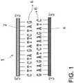
- a DNA molecule 1is schematically depicted and is structured in two strands 2, 4 positioned in antiparallel relation to one another. Each of the two opposing strands 2, 4 may be sequentially formed from repeating groups of nucleotides 6 where each nucleotide 6 consists of a phosphate group, 2-deoxyribose sugar and one of four nitrogen-containing bases.
- the nitrogen-containing basesinclude cytosine (C), adenine (A), guanine (G) and thymine (T).
- DNA strands 2, 4are read in a particular direction, from the top (called the 5' or "five prime” end) to the bottom (called the 3' or "three prime” end).
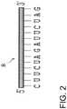
- RNA molecules 8, as schematically depicted in FIG. 2are polynucleotide chains, which differ from those of DNA 1 by having ribose sugar instead of deoxyribose and uracil bases (U) instead of thymine bases (T).
- hybridizationis the association, or binding, of two genetic sequences with one another. This process is predictable because the bases 6 in the molecules do not share an equal affinity for one another.
- T (or U) basesfavor binding with A bases while C bases favor binding with G bases.
- Bindingis mediated via hydrogen bonds that exist between the opposing base pairs. For example, A binds to T (or U) using two hydrogen bonds, while C binds to G using three hydrogen bonds.
- a hybridizing oligonucleotidei.e., a probe
- a probemay be used to determine and identify the sequence of bases in the molecule of interest.
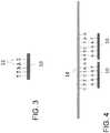
- Figure 3illustrates a probe 10 that is a short DNA sequence having a known composition. Probes 10 may be of any length depending on the number of bases 12 that they include. For example, a probe 10 that includes six bases 12 is referred to as a six-mer probe wherein each of the six bases 12 in the probe 10 may be any one of the known four natural base types A, T(U), C or G. Alternately, the probe may include non-natural bases.
- the total number of unique probes 10 in a libraryis dependent upon the number of bases 12 contained within each probe 10 and the number of different types of bases in the probes. If only the four natural bases are used in probe 10, the total number of probes in the library is determined by the formula 4 n (four raised to the n power) where n is equal to the total number of bases 12 in each probe 10. Formulas for other arrangements or types of bases are well known in the art. Accordingly, the size of the probe library can be expressed as 4 n n -mer probes 10. For the purpose of illustration, in the context of a six-mer probe, the total number of possible unique, identifiable probe combinations includes 4 6 (four raised to the sixth power) or 4096 unique six-mer probes 10.
- non-natural basesallows for the creation of probes that have spaces or wildcards therein in a manner that expands the versatility of the library, while reducing the number of probes that may be needed to reach the final sequence result.
- Probes that include universal bases organized into patterns with natural basesmay also be used, for example those described in U.S. Patent Nos. 7,071,324 , 7,034,143 , and 6,689,563 .
- the process of hybridization using probes 10, as depicted in Figure 4may begin by denaturing a double-stranded biomolecule, or by starting with a single-stranded biomolecule. Denaturing is accomplished usually through the application of heat or chemicals, such that the hydrogen bonds between adjacent strands of the biomolecule are broken.
- the term “melting”may be used interchangeably with the term “denaturing”.
- the hydrogen bonds between the two halves of an original double-stranded DNAmay be broken, leaving two single strands of DNA whose bases are now available for hydrogen bonding.
- a single-stranded probe 10may be introduced to the biomolecule 14 to locate portions of the biomolecule 14 that have a base sequence that correlates in a complementary manner to the sequence that is found in the probe 10.
- the denatured biomolecule 14 and a plurality of the probes 10 having a known sequenceare both introduced into a solution.
- the solutionmay be an ionic solution, such as a salt-containing solution.
- the mixturemay be mixed to facilitate binding of the probes 10 to the biomolecule 14 strand along portions thereof that have a matched complementary sequence.
- Hybridization of the biomolecule 14 using the probe 10may be accomplished before the biomolecule 14 is introduced into a nanopore sequencing apparatus or after the denatured biomolecule 14 has been placed into the cis chamber of such an apparatus. In this case, after the denatured biomolecule has been added to the cis chamber, buffer solution containing probes 10 with a known sequence is also added to the cis chamber and allowed to hybridize with the biomolecule 14 before the hybridized biomolecule is translocated.
- Probesare typically relatively short, e.g., 4-8 bases, and bind in a fully complementary manner to templates. Nevertheless, in methods employing oligonucleotide probes, it is recognized that probe binding is subject to both false negative and false positives. In the case of false negatives, not every region on the analyte that is complementary to a probe necessarily has a probe bound thereto at a given temperature, T. Likewise, in the case of false positives, probes occasionally bind to regions of the analyte that are not identically complementary, i.e., regions where, for example, there may be a single base or multiple base mismatch. In each of these instances, errors may be produced in the final map or sequence data.
- Embodiments of the present inventionare based upon the recognition that both thermodynamic effects and kinetic effects may be used to enhance probe binding to an analyte and to reduce false negatives and false positives.
- false positivesmay be reduced by inducing probes bound with one or more base mismatches to become unbound by, e.g., controlling the temperature of the reaction.
- a melting curve for DNAis depicted schematically in FIG. 5 . In that Figure, it can be seen that at a temperature T 1 double-stranded DNA (dsDNA) remains in its double-stranded configuration. At a higher temperature, T 2 , the strand has become completely denatured into two single-stranded DNA (ssDNA) templates.
- reaction temperatureAs applied to the binding of probes to ssDNA, this means that as reaction temperature increases, probe binding decreases. At a reaction temperature T M (the melting temperature) approximately half of all probes that can bind to the denatured analyte strand have done so.
- a base extension reactionsuch as a primer extension reaction, utilizing for example, a polymerase and one or more nucleotides.
- a primer complementary to a single-stranded DNA templateis typically employed.
- a DNA polymerasemay be used to add mononucleotides complementary to the template at the 3' end of the primer.
- a base extension reacionmay, for example, be a primer extension reaction.
- Such a primer extension reactionis also one of the reaction steps deployed in the classical polymerasse chain reaction method, as reviewed by Bell, Immunology Today (1989) 10:351-355 . Note that if the template comprises RNA, an RNA dependent DNA polymerase is employed.
- a denatured biomolecule analyte 15is formed from a single-stranded DNA (ssDNA) or RNA template 20 exposed to probes 10.
- the probesmay be ssDNA, RNA or other modified nucleotides that selectively hybridize to the analyte.
- the template 20is shown to include three regions 25, referred to herein as probe recognition sites, which are complementary to the probes 10 being used. As such, each of the regions 25 is a potential binding site for a probe 10. In this example, each probe 10 is a short, known ssDNA sequence.
- the probes 10may be of any length depending on the number of bases that they include. Each of the probes is preferably of an identical sequence, thereby causing the probes to selectively hybridize only to probe recognition sites 25 of the biomolecule template 20 that have a complementary sequence.
- the template 20 and probes 10are depicted prior to hybridization in FIG. 6a . For purposes of clarity in FIGs. 6a - 6d , probes 10 are shown having a small dot at the 3' end. This dot is not intended to signify a physical structure; rather, it is included simply to designate the 3' end of the probe.
- the biomolecule analyte 15is shown in FIG. 6b following hybridization of probes to the biomolecule template. Note that as shown in FIG. 6b , two probes (designated 10') have become bound at two probe recognition sites (designated 25'), while one probe 10 and probe recognition site 25 remain unbound. Were one to analyze the analyte following this step, the unbound probe recognition site 25 would be read as a false negative.
- a base extension reactionsuch as a primer extension reaction, utilizing for example, a polymerase and one or more nucleotides, is performed as depicted in FIG. 6c .
- a primer extension reactionutilizing for example, a polymerase and one or more nucleotides
- FIG. 6ca base extension reaction
- a primer complementary to a single-stranded DNA templateis typically employed.
- each of the bound probes 10'may be used as a primer in the base extension reaction.
- the probesare extended from their 3' ends along the template 20 to create duplex regions 40.
- the base extension reactioncauses the probes 10' to become more securely hybridized to the template.
- the base extension reactionbe limited in scope. If allowed to continue over extended lengths, the base extension may overwrite unbound probe recognition sites 25, rendering them as permanent false negatives. Instead, rather than extending a long distance from the 3' end of each probe, the base extension reaction may be terminated once the extensions have reached a length approximating the detection limits of the sequencing apparatus, such that the double-stranded region on the single-stranded template may have a length approximating the resolution of a detection apparatus. This leaves unbound probe recognition sites 25 unoccupied for subsequent probing reactions.
- Extension reactionsmay be terminated by the addition of dideoxynucleotides or other chain terminating nucleotides, such as 3'-amino-modified oligonucleotides, at a suitable time after the beginning of the extension reaction.
- chain terminating nucleotidesmay be included with the cognate nucleotides in the extension reaction. Suitable adjustment of the concentrations of cognate and terminating nucleotides may be used to limit the extent of elongation during the extension reaction.
- the extension of a subset of probes 10 to form duplex 40irreversibly binds the probes to the template 20 under the reaction conditions and removes them from the equilibrium between probes and template.
- hybridization of remaining unbound probes 10, to unbound probe recognition sites 25,is allowed to proceed as depicted in FIG. 6d .
- unbound probe recognition sites 25will subsequently become bound probe recognition sites 25', thereby reducing the number of false negatives on the analyte.
- the previously bound probes 10'acted as primers for the base extension reaction, they will have remained bound to the template. As such, it becomes possible to have substantially all probe recognition sites bound by complementary probes.
- the steps depicted in FIGs. 6a - 6dare intended as a schematic presentation and may have multiple elements (e.g., extension and termination) occurring simultaneously.
- the single-stranded templatemay be combined with a sequence-specific oligonucleotide probe, a polymerase, each of the four nucleotides used to synthesize DNA, (deoxyadeninetriphosphate, dATP; deoxycytidinetriphosphate, dCTP; deoxyguanosinetriphosphate, dGTP; and deoxy thymidinetriphosphate), as well as the dideoxy versions of each of those nucleotides (ddATP, ddCTP, ddGTP and ddTTP).
- ddATPdeoxyadeninetriphosphate
- dCTPdeoxycytidinetriphosphate
- dGTPdeoxyguanosinetriphosphate
- dTTPdeoxy thymidinetriphosphate
- the extension reactionis preferably as short as possible, but sufficiently long to permanently anchor the probe to the template. In practice, an extension of 80 to 100 bases may be preferable. Moreover, preferably, the extension reaction should not extend for a distance longer than can be resolved by a detector, e.g., currently about 300 bases.
- the duration of the extension reactioni.e., time before termination, depends on the polymerase used and the rate of incorporation of nucleotides. Termination of extension may be accomplised by removing polymerase, removing nucleotides, removing magnesium (preferably with ethylenediaminetetraacetic acid (EDTA)) to inactivate the polymerase, heat killing the polymerase, or by using mixtures of terminating and extending nucleotides.
- EDTAethylenediaminetetraacetic acid
- the base extensionis depicted in FIG. 6c .
- Probes that have served as primers for base extension reactionsremain bound to the analyte. Over a period of time, additional unhybridized probes will become bound as shown in FIG. 6d and act as primers for additional base extension reactions. Thus, eventually most, if not all, probe recognition sites become hybridized with complementary probes, and false negatives are eliminated. In some embodiments, it may be desirable to add the probes in a step prior to adding the polymerase and the deoxy- and dideoxy- nucleotides.
- False positiveshave previously been defined as instances where a probe has hybridized to a region of the analyte that is not identically complementary, i.e., a region where, for example, there may be a single base or multi-base mismatch. As shown in FIG. 5 , probes having mismatches generally have a lower T M than probes having no mismatches.
- the result of a lower T M for probes having mismatchesmeans that, during the base extension described with respect to FIGs. 6a - 6d , the analyte may be maintained at a temperature at or above the T M for a sufficient time, thereby causing mismatched probes to be denatured, i.e., melted, while extending correct hybridizations at complementary sites.
- mismatched probesBy allowing the enzymatic extension to occur for longer times, false positives may be substantially reduced.
- the time and temperaturemay be sufficient to melt substantially all probe mismatches.
- the probesare provided with tags that serve to make the probes more visible to a detector.
- suitable tagsinclude proteins, double-stranded DNA, single-stranded DNA, dendrimers, particles, or other molecules.
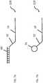
- a tagged probe 100includes a probe 10 having a sequence and a tag 60 connected to the 5' end of the probe sequence 10 by a linker 50.
- the tag 60may comprise a dsDNA segment, however, any of a wide variety of chemical/biological tags known to those skilled in the art may be employed.
- a tagged probe 110includes a probe 10 having a sequence and a tag 70 connected to the 5' end of the probe sequence 10 by a linker 50.
- FIG. 7a tagged probe 100includes a probe 10 having a sequence and a tag 70 connected to the 5' end of the probe sequence 10 by a linker 50.
- the tag 70may comprise a gold bead, a quantum dot, a fluorophore, etc.
- the tagsmake electrical fluctuations in sequencing systems more noticeable as the hybridized probes translocate through such systems.
- different tagsmay be used to help distinguish among different probes.
- a denatured biomolecule analyte 15is formed from a single-stranded DNA (ssDNA) or RNA template 20 exposed to tagged probes 100.
- the probesmay be ssDNA, RNA or other modified nucleotides that selectively hybridize to the analyte.
- the probesinclude a tag as described above.
- the template 20has been shown to include three probe recognition sites 25, which are complementary to the tagged probes 100 being used.
- the template 20 and tagged probes 100are depicted prior to hybridization in FIG. 8a .
- the biomolecule analyte 15is shown in FIG. 8b following hybridization of tagged probes to the biomolecule template.
- Two tagged probes(designated 100') have become bound at two probe recognition sites (designated 25'), while one tagged probe 100 and probe recognition site 25 remain unbound.
- each of the bound tagged probes 100'may be used as a primer in the base extension reaction.
- the probesare extended from their 3' ends along the template 20 to create duplex regions 40. Because they are attached to the 5' ends of the probes, the tags do not interfere with the base extension reaction.
- the base extension reactionbe limited in scope. If allowed to continue over extended lengths, the base extension may overwrite unbound probe recognition sites 25, rendering them as permanent false negatives. Instead, rather than extending a long distance from the 3' end of each probe, the base extension reaction may be terminated once the extensions have reached a length approximating the detection limits of the sequencing apparatus. This leaves unbound probe recognition sites 25 unoccupied for subsequent probing reactions.
- the analytemay be combined with a tagged sequence-specific oligonucleotide probe, a polymerase, each of the four nucleotides used to synthesize DNA, and the dideoxy forms of each of those nucleotides.
- a tagged sequence-specific oligonucleotide probeWhen placed in the presence of the analyte and maintained at T M for the tagged probe, at any given time, approximately 50% of the probes will hybridize. As discussed previously, a higher percentage of probes will hybridize if the hybridization reaction is carried out at a temperature below T M for the tagged probe. Partial hybridization is depicted in FIG. 8b .
- Tagged probes that have served as primers for base extension reactionsremain bound to the analyte. Over a period of time, additional tagged probes will become bound and act as primers for additional base extension reactions as shown in FIG. 8d . Over time most, if not all, probe recognition sites become hybridized with complementary tagged probes, and false negatives are eliminated. As described previously, in some embodiments, it may be desirable to add the probes in a step prior to adding the polymerase and the deoxy- and dideoxy-nucleotides.
- two or more pluralities of probesmay be used.
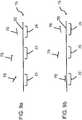
- a denatured biomolecule analyte 15is once again formed from a single-stranded DNA (ssDNA) or RNA template 20 exposed to a plurality of identical, sequence-specific oligonucleotide probes, i.e., a set of first probes 75 and a different plurality of identical, sequence-specific oligonucleotide probes, i.e., a set of second probes 76.
- the probesmay be ssDNA, RNA or other modified nucleotides that selectively hybridize to the analyte.
- the probes of the first probe set 75are identical to one another, and the probes of the second probe set 76 are also identical to one another, however the probes of the first set 75 are different than those of the second set 76.
- First probes 75may have a melting temperature T M1 which is higher than the melting temperature T M2 of the second probes 76.
- the template 20is shown to include two regions 25, referred to herein as first probe recognition sites, which are complementary to first probes 75 and one region 26, referred to herein as a second probe recognition site, which is complementary to second probes 76. As such, each of the regions 25 and 26 is a potential binding site for a probe.
- the template 20 and and first and second probes 75, 76are depicted prior to hybridization in FIG. 9a .
- probesare shown having a small dot at the 3' end. This dot is not intended to signify a physical structure; rather, it is included simply to designate the 3' end of the probe.
- Hybridizationis preferably carried out at a temperature that is at or below T M1 , but above T M2 . Because T M1 is higher than T M2 , the melting temperature of the second probe 76, the process conditions favor hybridization of the first probe 75.
- the biomolecule analyte 15is shown in FIG. 9b once hybridization of probes to the biomolecule template has begun. Note that as shown in FIG. 9b , one first probe (designated 75') has become bound at a first probe recognition site (designated 25'), while one first probe 75 and first probe recognition site 25 remain unbound. Second probe 76 and second probe recognition site 26 also remain unbound.
- first bound probe 75Following hybridization of the first probe, a base extension reaction off of the 3' end of first bound probe 75 is performed as depicted in FIG. 9c .
- the base extension 40causes bound first probes 75' to become more securely hybridized to the template.
- the base extension reactionbe limited in scope to prevent the extensions from overwriting unbound first 25 and second 26 probe recognition sites. This leaves unbound probe recognition sites unoccupied for subsequent probing reactions.
- the temperatureis lowered to T M2 or below and second probes 76 are allowed to hybridize to their complementary second probe binding sites 26. This is shown in FIG. 9f .
- bound second probes 76'act as primers for a base extension reaction.
- This reactionserves the same purpose as before; namely, to prevent bound second probes 76' from melting from the second probe recognition site. Process conditions are maintained for a period of time sufficient to allow substantially all second probe recognition sites 26 to become bound by second probes 76.
- FIGs. 9a - 9gare intended as a schematic presentation and may have multiple elements (e.g., extension and termination) occurring simultaneously. Although not depicted in FIGs. 9a - 9g , it is to be further understood that either or both of the first 75 and second 76 probe sets may include detectable tags.
- a ligation reactionis carried out to secure probes to the analyte.
- the use of ligases to enhance probe bindingis desirable in that ligases join probes with higher efficiency if the probes are perfectly complementary to the regions of the target analyte to which they are hybridized. As such, the use of ligases reduces enhanced binding of probes that contain mismatches with the analyte.
- ligationrefers to a method of joining two or more nucleotides to one another.
- the ligation methods described hereinutilize enzymatic ligation using ligases.
- ligasesinclude, but are not limited to DNA ligase I, DNA ligase II, DNA ligase III, DNA ligase IV, E. coli DNA ligase, T4 DNA ligase, T4 RNA ligase 2, T4 RNA ligase 2, T7 ligase, T3 DNA ligase, and thermostable ligases, including without limitation, Taq ligase and the like.
- ligase chain reactionis based on cycles of amplification consisting of ligation and subsequent dissociation of the ligated product from the template, so that each product can serve as a new template in subsenquent cycles of amplication.
- FIGs. 10a - 10bThe relevance of ligases to the methods of embodiments of the present invention is illustrated schematically in FIGs. 10a - 10b .
- FIG. 10aan 11-mer portion of the analyte 15 having the sequence TCAGAGCNNNA is shown.
- a 6-mer probe 10 having the sequence AGTCTCis shown hybridized to its complementary probe recognition site 25, (i.e., the sequence TCAGAG).
- a 5-mer oligonucleotide probe 11, optionally having degenerate sites (N)is hybridized to the analyte immediately adjacent to the 3' end of the probe 10. It is noted that probe 11 need not include degenerate sites; rather it could be perfectly complementary or it could include universal bases which hybridize equally well with each of the four cognate bases.
- the 5-mer probe 11becomes ligated to the probe 10, enhancing the ability of the probe to remain bound to the analyte even at temperatures above the melting temperature of the probe. (The ligation is represented in the Figure by a dot).
- FIG. 10balso shows a probe 10 and a 5-mer oligonucleotide probe 11 hybridized to the analyte. Unlike FIG. 10a however, a mismatch 13 is present between the probe 10 and the probe recognition site 25. As a result, upon carrying out an enzymatic ligation reaction, probes 10 and 11 do not become ligated. Thus, the probe 10 receives no enhancement of its bond to the analyte and both probe 10 and the 5-mer probe 11 may be melted from the analyte. Consequently, it is seen that the use of the ligation reaction enhances the accuracy of the probes by enhancing bonding only of those probes that are perfectly matched to their corresponding probe recognition sites.
- FIGs. 10c and 10dThe use of the ligation reaction as applied to embodiments of the present invention is shown in FIGs. 10c and 10d .
- the analyte 15includes three probe recognition sites 25. Each of these is shown with a hybridized probe. Two of the probes 10' are perfectly complementary to their corresponding probe recognition sites, but one probe 10" includes a mismatch.
- Several 5-mer probes 11, of the type described with respect to FIG. 10aare hybridized as well. One of the probes 11' is directly adjacent to the 3' end of a perfectly hybridized probe 10', and one of the probes 11" is directly adjacent to the 3' end of a hybridized probe 10" having a mismatch.
- probe 10as a 6-mer oligonucleotide
- probe 11as a 5-mer oligonucleotide
- Probesmay be of any length having utility in the applications described.
- probesmay include detectable tags.
- the incidence of false negative events resulting from secondary structure in the ssDNA or RNA templateis reduced.
- one reason for the inability of a probe to bind to a single-stranded DNA templateis the formation of secondary structure in that DNA template.
- a secondary structureis formed when a single-stranded molecule hybridizes to itself to form a hairpin, loop, etc. Secondary structures are generally undesirable in the methods disclosed herein, as they may appear to a detector as a hybridized probe.
- secondary structuresmay compete with the binding of the probe to a complementary site.
- secondary structuresmay promote clogging during translocation of templates or biomolecule analytes.
- the amount of false negative binding due to the secondary structureis determined by the relative stability of the probe bound structure as compared to that of the secondary structure. Thus, if the secondary structure has weak binding when the probe is tightly bound, very few false negative events are expected. However, if the secondary structure is very stable at the T M of the probe, then a high number of false negative binding events are expected because only a small proportion of the template are available for binding by probes.
- the template DNA of the biomolecule analytebe hybridized with the probe under conditions such that some of the complementary sites involved in the formation of secondary structure are open. That is, conditions may be chosen to insure that the equilibrium of the secondary structure does not result in 100% of the template being in the form of the secondary structure. As such, portions of the ssDNA template that do not have secondary structure are available for binding by the probe. Thus, if the hybridization is conducted at the T M of the secondary structure, at any instant, 50% of the molecules have no secondary and are available for binding by the probe. The conditions may be selected such that the template DNA available for binding by the probe become completely bound or such that only a fraction of the available binding sites may be bound.
- Structures in which the probe is hybridized to the templatemay be extended by a polymerase. As described above, it may be desirable to perform a limited extension of the probe. Following extension of bound probe, the template is heated in order to melt the secondary structure. The template may then be re-hybridized with the excess probe at the T M of the secondary structure. As before, the remaining single-stranded template is 50% available for binding by the probe. This cycle of hybridization, extension of probe, and denaturation may be repeated as many times as necessary to reduce the false negative rate resulting from the secondary structure. Temperatures or conditions other than the T M of the secondary structure may be used to perform the same conversions. Further, the conditions may be changed during each cycle of hybridization, extension, and denaturation.
- the analytei.e., at least a portion of the template or probes, may be coated to enhance its ability to be detected. Coating methods are described in detail in co-pending US Patent Application Publication No. 20100243449 . Broadly, coated biomolecules typically have greater uniformity in their translocation rates, which leads to a decrease in positional error and thus more accurate sequencing. Due to its increased diameter, a coated biomolecule generally translocates through a sequencing system at a slower speed than a non-coated biomolecule. The translocation is preferably slow enough so that a signal can be detected during its passage from a first chamber into a second chamber.
- binding moietiesinclude proteins such as, for example, RecA, T4 gene 32 protein, f1 geneV protein, human replication protein A, Pf3 single-stranded binding protein, adenovirus DNA binding protein, and E. coli single-stranded binding protein.
- the translocation rate or frequencymay be further regulated by introducing a salt gradient between the chambers.
- Exemplary salt concentration ratios of the cis to the trans side of the chambermay include, but are not limited to, 1:2, 1:4, 1:6, and 1:8.
- salt concentrationsmay range from about 0.5 M KCl to about 1 M KCl on the cis side and from about 1 M KCl to about 4 M KCl on the trans side.
- the signalis preferably strong enough to be detected using known methods or methods described herein.
- Exemplary signal-to-noise ratiosinclude, but are not limited to, 2:1, 5:1, 10:1, 15:1, 20:1, 50:1, 100:1, and 200:1. With a higher signal-to-noise ratio, a lower voltage may be used to effect translocation.
- the analytes described hereinmay be configured for detection of positional information in a nanopore and/or a fluidic channel, i.e., a microchannel or nanochannel system. Mapping of analytes may be carried out using electrical detection methods employing nanopores, nanochannels or microchannels using the methods described in U.S. Patent No. 8,246,799 . It is contemplated that such methods may be applied to analytes having either or both tagged and untagged probes.
- a nanoporemay have a diameter selected from a range of about 1 nm to about 1000 nm. More preferably the nanopore has a diameter that is between about 2.3 nm and about 100 nm. Even more preferably the nanopore has a diameter that is between about 2.3 nm and about 50 nm. Changes in an electrical property across a nanopore may be monitored as the analyte is translocated therethrough, with changes in the electrical property being used to distinguish regions of the analyte including probes, and regions of the analyte lacking probes.
- a measurable current 115 produced by electrodes 120, 122runs parallel to the movement of the target analyte 15, i.e., a DNA molecule having a tagged probe 100'.
- Variations in currentare a result of the relative diameter of the target analyte 15 as it passes through the nanopore 105.
- This relative increase in volume of the target analyte 15 passing through the nanopore 105causes a temporary interruption or decrease in the current flow through the nanopore, resulting in a measurable current variation.
- Portions of the target analyte 15 including a tagged probe 100'are larger in diameter than portions of the target analyte that do not include a probe.
- Analysis of the waveform 200permits differentiation between regions of the analyte including probes and regions without probes, based, at least in part, on the detected changes in the electrical property, to thereby determine probe locations and map at least a portion of the double-stranded DNA template.
- the waveform 200depicts the changes in a detected electrical property as the analyte passes through the nanopore, and may be interpreted as follows.
- Current measurement 210represents measured current prior to passage of the DNA molecule 15, i.e., the analyte, through the nanopore 105 from the cis side to the trans side.
- the currentis partially interrupted forming a first trough 220 in the recorded current.
- a further decrease in currentoccurs, causing a deeper, second trough 230 in the current measurement.
- a distal portion of the analytemay remain in the nanopore. This causes the measured current 240 to rise to approximately the level of the first trough 220.
- the measured current 250returns to a level approximating that of the initial level 210.
- the current variation measurementsare recorded as a function of time.
- the periodic variations in currentindicate where, as a function of relative or absolute position, the probes 100' have hybridized to complementary regions on the analyte 15. Since the probes are bound at probe recognition sites for the specific sequences of the probe, the relative or absolute position of the specific sequences associated with the recognition site for the particular probe employed may be determined. This allows mapping of those specific sequences on the analyte. Multiple maps produced using multiple probes may be generated.
- binding moietysuch as the protein RecA
- RecAmay further enhance detection of analytes and probe regions on analytes because the added bulk of the binding moiety coating causes greater current deflections.
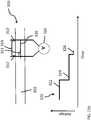
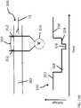
- an electrical propertysuch as electrical potential or current is measured during translocation of a DNA strand through a nanochannel or microchannel as shown in FIGs. 12 through 14 .
- a fluidic channel apparatusis shown schematically in FIG. 12 .
- the apparatus 300includes a fluidic microchannel or nanochannel 302.
- the fluidic channelmay be a microchannel having a width selected from a range of about 1 ⁇ m to about 25 ⁇ m or a nanochannel having a width selected from a range of about 10 nm to about 1000 nm.
- the depthmay be selected from a range of about 200 nm to about 5 ⁇ m, whereas in the case of a nanochannel, the depth may be selected from a range of about 10 nm to about 1000 nm. In either case, the channel may have a length selected from a range of about 1 ⁇ m to about 10 cm.
- a first pair of electromotive electrodes 304, 304'is connected to a voltage source 306 and positioned in a spaced apart relationship in the channel. When a potential is applied to the electromotive electrodes, these electrodes provide an electrical current along the channel and may be used to provide or enhance a driving force 308 to an analyte 15 in the channel. Other driving forces such as pressure or chemical gradients are contemplated as well.
- a second pair of electrodes 312, 312', i.e., detector electrodes,is positioned preferably substantially perpendicular to the channel in a spaced apart relationship to define a detection volume 314.
- the second pair of detector electrodes 312, 312'is connected to a detector 316, such as a voltmeter, which monitors an electrical property in the detection volume 314.
- a detector 316such as a voltmeter
- an electrical potential between the pair of detector electrodes 312, 312'is measured across the detection volume 314.
- FIGs. 13a - 13dThe operation of the device is depicted schematically in FIGs. 13a - 13d in which changes in an electrical property across a fluidic channel are monitored, as the analyte 15 is translocated therethrough, with the changes in the electrical property being indicative of probe-containing and probe-free regions.
- the first pair of electromotive electrodes 304, 304' and the current source 306have been omitted for clarity.
- the fluidic channel 302contains an analyte 15 traveling therethrough.
- An electrical property, in this case electrical potential,is measured and recorded across the detection volume 314 by the detector electrodes 312, 312' and the detector 316.
- the analyte 15is a DNA template upon which probes have been hybridized using the methods described previously.
- the DNA template and/or the probemay be coated with a binding moiety, such as the protein RecA, to enhance detection.
- a substantially constant voltage 322is measured across the detection volume. This voltage is shown in the waveform 320 of FIG. 13a . As the analyte 15 enters the detection volume 314, it causes an interruption or decrease in the electrical property measured in the detection volume. This interruption or decrease causes a first trough 324 to be exhibited in the waveform 320.
- FIG. 13bshows the device and waveform 320 once the portion of the target analyte 15 including the probe has entered the detection volume 314. Entry of the probe into the detection volume 314 causes a further interruption or decrease in the electrical property measured in the detection volume. This further interruption or decrease causes a second trough 326 to be exhibited in the waveform 320.
- the portion of the analyte 15 containing the probehas exited the detection volume 314; however, a distal portion of the analyte 15 may still be present in the detection volume.
- the waveform 320has returned to a level 328 approximating that detected when the initial portion of the analyte first entered the detection volume.
- the analyte 15has fully exited the detection volume 314.
- the waveform 320has returned to a level 330 approximating that detected prior to initial entry of the analyte into the detection volume.
- Analysis of the waveform 320permits differentiation between probe-containing and probe-free regions of the analyte, based, at least in part, on the detected changes in the electrical property. As such, it is possible to determine probe locations and map at least a portion of the analyte.
- the apparatus 400comprises a fluidic microchannel or nanochannel 402.
- the fluidic channelmay be a microchannel having a width selected from a range of about 1 ⁇ m to about 25 ⁇ m or a nanochannel having a width selected from a range of about 10 nm to about 1 ⁇ m.
- the depthmay be selected from a range of about 200 nm to about 5 ⁇ m, whereas in the case of a nanochannel, the depth may be selected from a range of about 10 nm to about 1 ⁇ m.
- the channelmay have a length selected from a range of about 1 ⁇ m to about 10 cm.
- a first pair of electromotive electrodes 404, 404'is connected to a voltage source 406 and positioned in a spaced apart relationship in the channel. When a potential is applied to the electromotive electrodes, these electrodes provide an electrical current along the channel and may be used to provide or enhance a driving force 408 to an analyte 15 in the channel. Other driving forces such as pressure or chemical gradients are contemplated as well.
- Multiple detector electrodes 412, 414, 416, 418,are positioned preferably perpendicular to the channel in a spaced apart relationship to define a plurality of detection volumes between adjacent detector electrodes.
- detector electrodes 412 and 414define detection volume 420
- detector electrodes 414 and 416define detection volume 422
- detector electrodes 416 and 418define detection volume 424.
- the detector electrodesare each connected to detectors 426, 428, 430 such as voltmeters, which monitor an electrical property in each detection volume. In the embodiment where the detectors are voltmeters, a drop in electrical potential is measured across each detection volume. Operation of the apparatus is similar to that of the system of FIGs. 13a - 13d , with the exception that additional waveforms are generated due to the presence of additional detection volumes. The additional waveforms may be combined to further improve the quality of the data being generated by the device.
- detector electrodes and detection volumesare not intended to limited to those depicted in FIG. 14 . Rather, any number of detection volumes may be included along the length of the fluidic channel. Further, the detector electrodes and detection volumes need not be evenly spaced, evenly sized or directly adjacent to one another. Various detection volume sizes, spacing and configurations are contemplated.
Landscapes
- Chemical & Material Sciences (AREA)
- Life Sciences & Earth Sciences (AREA)
- Organic Chemistry (AREA)
- Proteomics, Peptides & Aminoacids (AREA)
- Zoology (AREA)
- Wood Science & Technology (AREA)
- Health & Medical Sciences (AREA)
- Engineering & Computer Science (AREA)
- Analytical Chemistry (AREA)
- Microbiology (AREA)
- Immunology (AREA)
- Molecular Biology (AREA)
- Biotechnology (AREA)
- Biophysics (AREA)
- Physics & Mathematics (AREA)
- Biochemistry (AREA)
- Bioinformatics & Cheminformatics (AREA)
- General Engineering & Computer Science (AREA)
- General Health & Medical Sciences (AREA)
- Genetics & Genomics (AREA)
- Chemical Kinetics & Catalysis (AREA)
- Measuring Or Testing Involving Enzymes Or Micro-Organisms (AREA)
Description
- The present invention relates generally to methods for enhancing the binding of oligonucleotide probes to DNA and RNA samples for analysis. Mapping and sequencing of the DNA and RNA samples are contemplated herein.
- A number of different approaches for sequencing nucleic acids exist. The traditional methods are the dideoxy-chain termination method described bySanger et al., Proc Natl. Acad. Sci. USA, (1977) 74: 5463-67 and the chemical degradation method described byMaxam et al., Proc. Natl. Acad. Sci. USA, (1977) 74: 560-564. Of these two methods, the Sanger procedure has been the most widely used. The original Sanger method relied on radioactive labeling of the reaction products and separation of the reaction products by slab gel electrophoresis.
- Both the Sanger and Maxam methods are time- and labor-intensive. The start of the Human Genome Project was the impetus for the development of improved, automated systems to perform Sanger sequencing. As a result, detection of fluorescence has replaced autoradiography and capillary electrophoresis has replaced the ultrathin slab gels originally used to separate reaction products. Automated sequencers have been developed and are capable of processing large numbers of samples without operator intervention.
- The completion of the Human Genome Project has refocused the need for new technologies that are capable of rapidly and inexpensively determining the sequence of human and other genomes. There is has been much discussion in recent years about personalized medicine. The vision of personalized medicine involves every individual having his or her complete genome sequenced at high accuracy and using this information to guide clinical care, specifically for risk stratification of patients and pharmacogenomics.
- In recent years, a number of technological advances have been developed enabling a great reduction in the cost of sequencing and substantially increasing the amount of sequence data produced. Most sequencing methods currently available utilize optical detection for the determination of the DNA sequence. The most prevalent sequencing methods are referred to as sequencing by synthesis (SBS).
- SBS typically consists of the stepwise synthesis of a strand of DNA that is complementary to a template sequence from the target genome to be sequenced. The SBS methods can be divided into those that are performed in batch mode and those that are performed in real-time. The batch mode processes rely on the stepwise synthesis of the new DNA strand with the limitation that the synthesis is only allowed to proceed for one nucleotide position, for one nucleotide type, or for the combination of one nucleotide position and one nucleotide type. The incorporation of the nucleotide occurs in parallel for large numbers of templates. Detection is achieved using a variety of methods.
- The batch mode processes utilizing a single nucleotide type are used by Roche for pyrosequencing with the 454 platform. The Roche technology (see, e.g.,Margulies et al. (2005) Nature, 437:376-380;
U.S. Patent Nos. 6,274,320 ;6,258,568 ;6,210,891 ) utilizes pyrosequencing. The method depends on several enzymes and cofactors to produce luminescence when a nucleotide is incorporated. A single nucleotide species is introduced into a large number of small reaction vessels each containing multiple copies of a single template. The incorporation of the nucleotide is accompanied by light emission. When the reaction has run to completion, the reagents are washed from the reaction volumes and a next nucleotide and its required reagents are washed into the reactions. Each template is thus extended in an iterative fashion, one nucleotide at a time. Multiple incorporations of the same nucleotide require the quantitative determination of the amount of light emitted. Homopolymer tracts in templates may be difficult to accurately sequence as the incremental amount of light emitted for each subsequent position in the homopolymer becomes small compared to the total amount emitted. - In other variations of the SBS method, platforms by Helicos (see, e.g.,Quake et al Proc. Nat. Acad. Sci. USA (2003) 100: 3960-3964;
U.S. Patent Nos. 6,818,395 ;6,911,345 ;7,297,518 ;7,462,449 and7,501,245 ), Illumina (see, e.g., Bennett et al. Pharmacogenomics (2005) 6:373-382), and Intelligent Bio-Systems (see, e.g.,Ju et al. Proc. Nat. Acad. Sci. USA (2006) 103:19635-19640) allow only the incorporation of a single nucleotide at each step. Template strands are attached to a solid support and a primer sequence is annealed. A polymerase is used to extend the primer to make a complement to the template. The nucleotides are derivatized such that after the incorporation of a single nucleotide, the growing strand is incapable of further extension. The nucleotides are further derivatized to make them fluorescent. In the Helicos technology, the four nucleotides are labeled with the same fluorescent tag. This requires that each nucleotide type be added separately. In contrast, the Illumina and Intelligent Bio-Systems technologies utilize four different fluorescent tags so that a mixture of all four derivatized nucleotides may be added at the same time. For both technologies, the incorporation of a nucleotide is accompanied by the appearance of fluorescence in the growing strand. In the case of Illumina, the wavelength of the fluorescence emission indicates the identity of the newly incorporated nucleotide. In the Helicos technology, only a single nucleotide type is added at each cycle. Thus, the appearance of fluorescence at a position on the solid support indicates the incorporation of the added nucleotide for that template. Templates that do not incorporate the nucleotide present in the reaction remain dark. - Following the observation of any incorporated fluorescence, the blocking groups and fluorescent tags are removed prior to the next cycle. Multiple cycles result in the acquisition of sequence data for many templates in a single run. The instrumentation typical for these technologies is said to allow for the automated acquisition of sequence information for hundreds of thousands to millions of templates in parallel.
- SBS methods may also be performed in real-time. In particular, polymerase is used to incorporate fluorescently labeled nucleotides and the fluorescence is observed during DNA strand synthesis. The four nucleotides are labeled with different fluorescent tags. The fluorescent tags are attached to the terminal phosphate of the nucleotide triphosphate. During incorporation of the nucleotide into the growing strand the fluorophore is released to solution and the growing strand remains non-fluorescent. The identity of the incorporated strand is determined while the nucleotide resides in the active site of the enzyme and before the cleaved diphosphate is released to bulk solution.
- The fluorescence of the incorporated nucleotide typically is measured in the presence of a background fluorescence from a much larger concentration of unincorporated nucleotide. Pacific Biosciences (see, e.g.,
US Patent Nos. 7,170,050 ;7,302,146 ;7,315,019 ;7,476,503 ; and7,476,504 ) identifies the incorporated nucleotide based on the residence time in the polymerase active site. Fluorescence emission from the active site for an appropriate time indicates incorporation and the emission wavelength determines the identity of the incorporated nucleotide. Polymerase is attached to the bottom of zero-mode waveguides. Zero-mode waveguides are reaction cells whose dimensions limit the passage of light from the excitation sources. Thus, only fluorescent tags close to the bottom surface of the reaction volume are excited. - Other recently developed methods to sequence DNA rely on hybridization and ligation. Both the SOLiD and Complete Genomics technologies rely on the combination of hybridization and ligation. The SOLiD system (Life Technologies) immobilizes short template strands via an adapter. A primer and a pool of labeled oligonucleotides containing two fixed positions and six degenerate positions is hybridized to the template. The primer hybridizes to the adaptor. Each pool consists of 16,384 different sequences. Four fluorescent dyes are used to label the oligonucleotides in a pool in a fashion that creates four subsets from the sixteen combinations at the two fixed positions. Thus, each fluorescent tag is associated with four of the sixteen possible combinations. Following hybridization, a ligase is added and any probes in the pool that hybridized contiguously with the primer are ligated to the primer. The fluorescence of the hybridized and ligated product is determined. The fluorescence defines which subset of sequences hybridized to the template and ligated to the primer. The terminal three bases and the associated fluorescent tag are cleaved from the hybridized and ligated oligonucleotide. Subsequent rounds of another round of hybridization, ligation, and cleavage are performed. In this first series of reactions, each cycle identifies a subset for the pair of nucleotides in the template that is 5 nucleotides downstream from subset of pairs that were identified in the last cycle. After several cycles, the primer, and the oligonucleotides that have been ligated to it, is washed off the template.
- The entire procedure is repeated starting with a primer that is one nucleotide shorter than the original primer, then with primers that are two, three, and four nucleotides shorter than the original primer. These subsequent rounds shift the frame of interrogation so that the bases that make-up the template strand can be identified from the union between the two subsets of reaction that overlapped at that position.
- Complete Genomics technology utilizes a similar hybridization and ligation method (see, e.g.,
US Patent Application Publication Nos. 20080234136 ;20090005252 ;20090011943 ; and20090176652 ). In the Complete Genomics technology, a primer is hybridized to an adaptor that is attached to the end of the template. A series of pools of oligonucleotides is constructed. In each pool, the nucleotide at a single position is identified by using four-color fluorescence. The remaining positions are degenerate. The first pool is hybridized to the template. Oligonucleotides that hybridize adjacent to the primer are subsequently ligated. After washing excess oligonucleotides away, the fluorescence of the ligated oligonucleotide identifies the nucleotide at the defined position in that pool. The ligated primer and oligonucleotide are washed off the template and the process is repeated with the next pool of oligonucleotides that probe the next position down from the primer. - The SBS and hybridization-ligation methods generate short pieces or reads of DNA sequence. While the short reads can be used to re-sequence human genomes, they are not favorable for thede novo assembly of human genomes. With the recent realization that human genomes contain large numbers of inversions, translocations, duplications, and indels (e.g., mutations that include both insertions, deletions, and the combination thereof), the quality of human genome data from short reads is even more suspect. Genetic rearrangements are even more prevalent in cancer.
- While short read technology methods that incorporate paired-end reads have been proposed and the length of the sequence data from these technologies has increased incrementally over the last two years, it is clear that longer read technologies are necessary for the accurate assembly of human genome data.
- In addition to the undesirable nature of short reads, all of the DNA sequencing methods described above employ optical detection. The throughput of optical methods limits the ultimate performance characteristics of any of these sequencing technologies. Optical methods are capable of identifying single molecules. However, the time required to observe and accurately identify events is typically too slow to meet the need for higher throughput. While the current generation of sequencing technologies has lowered the cost of sequencing by orders of magnitude in comparison to the methods used to sequence the first human genomes, the methods remain too slow, costly, and inaccurate for routine analysis of human genomes.
- In methods employing oligonucleotide probes, it is recognized that probe binding is subject to both false negatives and false positives. In the case of false negatives, not every region on the analyte that is complementary to a probe necessarily has a probe bound thereto at a given temperature, T. Likewise, in the case of false positives, probes bind to regions of the analyte that are not identically complementary, i.e., regions where, for example, there may be a single base mismatch. In both of these instances, errors may be produced in the final map or sequence data.
- A need exists for efficient methods and devices capable of rapid and accurate nucleic acid sequencing forde novo assembly of human genomes. It is desirable to have long read lengths and to use as little nucleic acid template as possible. Moreover, single-molecule optical detection of DNA has limitations with respect to sensitivity and therefore speed. Thus, there remains a need for improved methods and devices for the analysis of biopolymers, including methods and devices for mapping and sequencing such biopolymers. A need also exists for improved methods by which probes are bound to samples to be analyzed to thereby reduce the occurrence of false positive and false negative probe binding.
- The embodiments of the invention provide assay methods for preparing analyte samples for mapping and sequencing using nanopore, microchannel or nanochannel analysis devices.
- Embodiments of the present invention relate broadly to the recognition and use of thermodynamic effects and kinetic effects to improve binding of oligonucleotide probes to DNA and RNA sample analytes. These effects may be used to reduce both false negatives that result from probes failing to bind at complementary sites on the analyte as well false positives resulting from probes binding at sites having complementary mismatches. Improvements in probe binding provide enhanced accuracy when using the probes to derive maps and sequences of the samples being analyzed.
- More particularly, in one aspect, embodiments of the invention relate to a method for preparing a biomolecule analyte which includes the steps of a) providing a single-stranded DNA or RNA template; b) hybridizing a plurality of identical, sequence-specific oligonucleotide probes to the template; c) after hybridizing the plurality of identical probes, conducting a base extension reaction from a 3' end of a hybridized probe along the template to create duplex regions; d) terminating the base-extension reaction, thereby leaving a portion of the template single-stranded, which leaves the unbound probe recognition sites unoccupied for subsequent probing reactions; and e) thereafter, allowing additional unhybridized probes from the plurality of identical probes to hybridize to the unbound probe recognition sites of the template to prepare the biomolecule analyte.
- One or more of the following features may be included. The base extension reaction may be allowed to produce a double-stranded region on the single-stranded template of a length approximating the resolution of a detection apparatus. The base extension reaction and the termination may carried out simultaneously. Following termination of the base extension reaction, the analyte may be maintained at a temperature for a time sufficient to melt probe mismatches, e.g., sufficient to melt substantially all probe mismatches. This process may be carried out one or more times. The probes may be provided with tags, such as double stranded DNA, gold beads, quantum dots, or fluorophores. A at least a portion of the template or probes may be provided with a protein coating, e.g., RecA, T4 gene 32 protein, f1 gene V protein, human replication protein A, Pf3 single-stranded binding protein, adenovirus DNA binding protein, orE. coli single-stranded binding protein.
- The single-stranded DNA or RNA template may include one or more secondary structures. In such cases, the secondary structure may be denatured following termination of any of the base extension reactions. In particular, in another aspect of the invention, a method for preparing a biomolecule analyte includes providing a single-stranded DNA or RNA template comprising one or more secondary structures. A plurality of identical, sequence-specific oligonucleotide probes is hybridized to the template. After hybridizing the plurality of identical probes, a base extension reaction is conducted from a 3' end of a hybridized probe along the template to create duplex regions. The base-extension reaction is terminated, thereby leaving a portion of the template single-stranded, which leaves the unbound probe recognition sites unoccupied for subsequent probing reactions. The template is denatured by applying heat or chemicals to break at least a portion of said one or more secondary structures. The hybridizing, base extension reaction, termination, and denaturing steps are then repeated at least one additional time with a different plurality of identical, sequence-specific oligonucleotide probes to prepare the biomolecule analyte.
- One or more of the following features may be included. At least a portion of the probes may include tagged probes. At least a portion of the template or probes may be coated with a protein. The base extension reaction and the termination may be carried out simultaneously.
- In some embodiments of the invention, two or more probes may be used. In another aspect, embodiments of the the invention include a method for preparing a biomolecule analyte, the method including providing a single-stranded DNA or RNA template, providing a first plurality of identical, sequence-specific oligonucleotide probes having a first melting temperature, and a second plurality of identical, sequence-specific oligonucleotide probes having a second melting temperature, the first melting temperature being higher than the second melting temperature. The first plurality of probes has a different sequence than the second plurality of probes. The probes from the first plurality are hybridized to the template at a temperature between the second melting temperature and the first melting temperature, and a first base-extension reaction is conducted from a 3' end of a hybridized from the first plurality of probes along the template to create duplex regions probe. The first base extension-reaction is terminated thereby leaving a portion of the template simple-stranded, which leaves the unbond probe recognition sites unoccupied for subsequent probing reactions, and then additional unhybridized probes from the first plurality of probes are allowed to hybridize to the template. A second base-extension reaction is then conducted from a 3' end of a hybridized probe from the first plurality of probes along the template to create duplex regions and is terminated. Finally, probes from the second plurality of identical, sequence-specific oligonucleotide probes are hybridized to the template at a temperature equal to or below the second melting temperature to prepare the biomolecule analyte.
- One or more of the following features may be included. At least a portion of the probes may include tagged probes. At least a portion of the template or probes may be coated with a protein. The first base extension reaction and its termination may be carried out simultaneously. The second base extension reaction and its termination may be carried out simultaneously.
- Optionally, a third base-extension reaction may be conducted to extend from a 3' end of a hybridized probe from the second plurality of probes along the template to create duplex regions. This is followed by termination of the base extension reaction and allowing additional unhybridized probes from the second plurality of probes to hybridize to the template. The third base extension reaction and its termination may be carried out simultaneously.
- Additional base extension reactions may be allowed as desired. For example, a fourth base-extension reaction may be conducted in the at least one single-stranded region from a 3' end of a hybridized probe from the second plurality of probes, along the template to create duplex regions and then terminated. The fourth base-extension reaction and its termination may be carried out simultaneously.
- In some embodiments of the invention, an enzymatic ligation may be substituted for the base extension reaction. Accordingly, in yet another aspect, embodiments of the invention include a method for preparing a biomolecule analyte by providing a single-stranded DNA or RNA template. A first plurality of identical, sequence-specific oligonucleotide probes and a second plurality of identical oligonucleotide probes are provided, the first plurality being different from the second plurality. The first plurality of probes and the second plurality of probes are hybridized to the template. An enzymatic ligation reaction is conducted to ligate hybridized probes from the first plurality to an adjacent probe from the second plurality of identical oligonucleotide probes, terminating the ligation reaction by increasing the temperature of the template, with the ligated probes remaining hybridized to the template, and allowing additional unhybridized probes from the first plurality of probes to hybridize to unbound probe recognition sites of the template to prepare the biomolecule analyte.
- One or more of the following features may be included. The probes from the second plurality may each include one degenerate or universal site. At least a portion of the first plurality of probes and/or second plurality of probes may include tagged probes. At least a portion of the template and/or first plurality of probes and/or second plurality of probes may be coated with a protein.
- The biomolecule analytes prepared by the methods described herein may be used to map or sequence biomolecules using nanopores or fluidic channels such as nanochannels and microchannels. For example, any of the biomolecule analytes prepared by the disclosed methods may be analyzed as follows. An apparatus may be provided, the apparatus having a first fluid chamber, a second fluid chamber, a membrane positioned between the first and second chambers and a nanopore extending through the membrane such that the first and second chambers are in fluid communication via the nanopore. The biomolecule analyte may be introduced into the first chamber and translocated from the first chamber through the nanopore and into the second chamber. Changes in an electrical property across the nanopore may be monitored as the biomolecule analyte is translocated therethrough, the changes in the electrical property corresponding to locations along the biomolecule analyte containing probes. The changes in the electrical property as a function of time may be recorded.
- Moreover, any of the biomolecule analytes prepared by the disclosed methods may be analyzed as follows. The biomolecule analyte may be disposed in a fluidic nanochannel or microchannel. A potential may be applied along the fluidic channel. The biomolecule analyte may be translocated from a first end of the fluidic channel to a second end of the fluidic channel. Electrical properties may be detected as the biomolecule analyte moves through the fluidic channel, the electrical properties corresponding to at least one detector volume in the fluidic channel, each detector volume being defined by two or more sensing electrodes disposed along the length of the fluidic channel, with the detected electrical signals indicating locations of hybridized probes along the biomolecule analyte.
FIG. 1 is a schematic depiction of a DNA molecule.FIG. 2 is a schematic depiction of an RNA molecule.FIG. 3 is a schematic depiction of a hybridizing oligonucleotide probe.FIG. 4 is a schematic depiction of a single-stranded DNA molecule hybridized with two identical probes.FIG. 5 is a schematic representation of a melting curve showing the relative amounts of double-stranded DNA versus single-stranded DNA over a range of temperatures.FIGs. 6a - 6d are schematic depictions of an assay preparation method in accordance with an embodiment of the invention in which oligonucleotide probes are hybridized to a single-stranded DNA or RNA template, a base extension reaction is carried out, and a subsequent hybridization of remaining unbound probes is allowed to proceed.FIGs. 7a and 7b are schematic depictions of tagged probes useful in connection with embodiments of the present invention.FIGs. 8a - 8d are schematic depictions of an assay preparation method in accordance with an embodiment of the invention in which tagged oligonucleotide probes are hybridized to a single-stranded DNA or RNA template, a base extension reaction is carried out, and a subsequent hybridization of remaining unbound tagged probes is allowed to proceed.FIGs. 9a - 9g are schematic depictions of an assay preparation method in accordance with an embodiment of the invention in which two different oligonucleotide probes are employed. In this embodiment, a first probe set is hybridized to a single-stranded DNA or RNA template using the methods of embodiments of the invention, and then a second probe set is hybridized to the analyte.FIGs 10a - 10d are schematic depictions of an assay preparation method in accordance with an embodiment of the invention in which ligation is used to enhance hybridization of probes to an analyte.FIG. 11a is a schematic depiction of an assay method in accordance with an embodiment of the invention showing a DNA molecule having a tagged probe in a nanopore apparatus.FIG. 11b is a schematic depiction of an assay method in accordance with an embodiment of the invention showing a current measurement waveform as a DNA molecule having a tagged probe translocates through the nanopore apparatus ofFIG. 11a .FIG. 12 is a schematic depiction of an assay method in accordance with an embodiment of the invention showing a nanochannel or microchannel apparatus useful for mapping the analytes of embodiments of the present invention.FIG. 13a is a schematic depiction of an assay method in accordance with an embodiment of the invention showing an electrical potential measurement as a DNA molecule having a tagged probe enters a detection volume in the apparatus ofFIG. 12 .FIG. 13b is a schematic depiction of an assay method in accordance with an embodiment of the invention showing an electrical potential measurement as a tagged probe on a DNA molecule enters a detection volume in the apparatus ofFIG. 12 .FIG. 13c is a schematic depiction of an assay method in accordance with an embodiment of the invention showing an electrical potential measurement as a tagged probe on a DNA molecule exits a detection volume in the apparatus ofFIG. 12 .FIG. 13d is a schematic depiction of an assay method in accordance with an embodiment of the invention showing an electrical potential measurement as a DNA molecule having a tagged probe exits a detection volume in the apparatus ofFIG. 12 .FIG. 14 is a schematic depiction of an assay method in accordance with an embodiment of the invention showing a nanochannel or microchannel apparatus having multiple detection volumes.- Embodiments of the present relate generally to methods for enhancing the binding of oligonucleotide probes to DNA and RNA samples for analysis.
- As used in this description and the accompanying claims, the following terms shall have the meanings given, unless the context indicates otherwise:
- A "template" or "target" means a biomolecule, for example, having sequence information that is to be determined using embodiments of the present invention. The target or template may be a biomolecule such as deoxyribonucleic acid, a ribonucleic acid, a protein, or a polypeptide. The target or template may be single-stranded or double-stranded.
- A "probe" means any molecule or assembly of molecules capable of sequence-specific covalent or non-covalent binding to a template. Accordingly, a sequence-specific probe is capable of binding to a portion of the template having a complementary sequence.
- A "biomolecule analyte" is any molecule or assembly of molecules, e.g., a template having probes bound thereto, that is to be analyzed. An exemplary biomolecule analyte may include a single-stranded DNA or RNA template, with one or more sequence-specific oligonucleotide probes hybridized to a corresponding complementary portion of the template; a binding moiety may coat at least a portion of the single-stranded DNA or RNA template and/or probes.
- A "tag" means a moiety that is attached to a probe in order to make the probe more visible to a detector. These tags may be proteins, double-stranded DNA, single- stranded DNA, dendrimers, particles, or other molecules.
- A "false negative" means that not every region on the analyte that is complementary to a probe necessarily has a probe bound thereto at a given temperature, T.
- A "false positive" means a probe that has bound to a region of the analyte that is not identically complementary, i.e., a region where, for example, there may be a single base mismatch.
- In one embodiment, a biomolecule of interest is hybridized with the entire library of probes of a given length. For example, the biomolecule of interest can be hybridized with the entire universe of 4096 (i.e., 46) possible six-mers. The hybridization can be done sequentially (i.e., one probe after another) or in parallel (i.e., a plurality of biomolecules of interest are each separately hybridized simultaneously with each of the possible probes.) Alternatively, the probes can be separated from each other in both space and time. Additionally, more than one probe type may be hybridized to the same biomolecule of interest at the same time.
- The set of probes used to perform sequencing may be a subset of the complete library of probes of a given length, such as about 85%, 75%, 65%, 55%, 45%, or 33% of the library. For instance, if sequencing is performed on a biomolecule that starts as double-stranded DNA, then only one-half of the probes that make up a library may be needed. Other subsets of the library may be designed to allow sequencing as well. If some information concerning the target sequence is known prior to performing the sequencing reaction, it may be possible to use a small subset of the total library. For instance, if the sequencing reaction is being performed to determine if single nucleotide polymorphisms are present with respect to a reference sequence, then a small number of probes with respect to the complete library may be used. Alternatively, the set of probes may not all be the same length. In an embodiment, a set of at least two probes may be used for hybridization, rather than an entire library of probes or subset thereof. In another embodiment, probes may be separated by (GC) content or other determinants of probe binding strength, in order to allow for optimization of reaction conditions. By separating the probes based on relative properties, multiple probes may be incorporated into a single hybridization reaction. Further, the probes may be grouped based on their related optimum reaction environment preferences. In yet another embodiment, pools of probes may be simultaneously hybridized to a biomolecule of interest. A pool of probes is a group of probes of different composition, each of which may likely be present in many copies. The composition of the probes may be chosen so as to reduce the chance of competitive binding to the biomolecule of interest. Alternatively, the composition of multiple pools may be chosen so that the same competitive binding is not present in all pools occupied by a single probe.
- It should be understood that the methods of embodiments of the present invention are not intended to be limited solely to sequencing. As such, embodiments of the invention can be used to provide accurate maps of analytes. In particular, rather than employing a library of probes as described above, in mapping applications, one or more sets of sequence-specific probes can be used to map, with high accuracy, the specific location of regions on the analyte which are complementary to such probes.
- In still another embodiment, the probes may include tags, thereby enhancing detection as the hybridized probes translocate through the sequencing system. In addition, different tags may be used to help distinguish among the different probes. These tags may be proteins, double-stranded DNA, single-stranded DNA, particles, or other molecules.
- It should be understood that embodiments of the invention are not intended to be limited strictly to DNA and RNA oligonucleotide probes. Rather, it is envisioned that oligonucleotide analog probes such as those comprising LNAs, PNAs, 2'-methoxy nucleotide analogs, or other analogs may be used as well.
- In one embodiment, the process of sequencing a biomolecule such as single strands of DNA or RNA using one or more probes may be performed as follows. Suitable processes are also described in
U.S. Serial No. 11/538,189 , published asU.S. Publication No. 2007/0190542 . Referring toFigure 1 , aDNA molecule 1 is schematically depicted and is structured in twostrands strands nucleotides 6 where eachnucleotide 6 consists of a phosphate group, 2-deoxyribose sugar and one of four nitrogen-containing bases. The nitrogen-containing bases include cytosine (C), adenine (A), guanine (G) and thymine (T).DNA strands RNA molecules 8, as schematically depicted inFIG. 2 , are polynucleotide chains, which differ from those ofDNA 1 by having ribose sugar instead of deoxyribose and uracil bases (U) instead of thymine bases (T). - Traditionally, in determining the particular arrangement of the
bases 6 and thereby the sequences of the molecules, a process called hybridization may be utilized. The hybridization process is the association, or binding, of two genetic sequences with one another. This process is predictable because thebases 6 in the molecules do not share an equal affinity for one another. T (or U) bases favor binding with A bases while C bases favor binding with G bases. Binding is mediated via hydrogen bonds that exist between the opposing base pairs. For example, A binds to T (or U) using two hydrogen bonds, while C binds to G using three hydrogen bonds. - A hybridizing oligonucleotide, i.e., a probe, may be used to determine and identify the sequence of bases in the molecule of interest.
Figure 3 illustrates aprobe 10 that is a short DNA sequence having a known composition.Probes 10 may be of any length depending on the number ofbases 12 that they include. For example, aprobe 10 that includes sixbases 12 is referred to as a six-mer probe wherein each of the sixbases 12 in theprobe 10 may be any one of the known four natural base types A, T(U), C or G. Alternately, the probe may include non-natural bases. - In this regard, the total number of
unique probes 10 in a library is dependent upon the number ofbases 12 contained within eachprobe 10 and the number of different types of bases in the probes. If only the four natural bases are used inprobe 10, the total number of probes in the library is determined by the formula 4n (four raised to then power) wheren is equal to the total number ofbases 12 in eachprobe 10. Formulas for other arrangements or types of bases are well known in the art. Accordingly, the size of the probe library can be expressed as 4nn-mer probes 10. For the purpose of illustration, in the context of a six-mer probe, the total number of possible unique, identifiable probe combinations includes 46 (four raised to the sixth power) or 4096 unique six-mer probes 10. The inclusion of non-natural bases allows for the creation of probes that have spaces or wildcards therein in a manner that expands the versatility of the library, while reducing the number of probes that may be needed to reach the final sequence result. Probes that include universal bases organized into patterns with natural bases may also be used, for example those described inU.S. Patent Nos. 7,071,324 ,7,034,143 , and6,689,563 . - The process of
hybridization using probes 10, as depicted inFigure 4 , may begin by denaturing a double-stranded biomolecule, or by starting with a single-stranded biomolecule. Denaturing is accomplished usually through the application of heat or chemicals, such that the hydrogen bonds between adjacent strands of the biomolecule are broken. The term "melting" may be used interchangeably with the term "denaturing". - The hydrogen bonds between the two halves of an original double-stranded DNA may be broken, leaving two single strands of DNA whose bases are now available for hydrogen bonding. After the
biomolecule 14 has been denatured, a single-strandedprobe 10 may be introduced to thebiomolecule 14 to locate portions of thebiomolecule 14 that have a base sequence that correlates in a complementary manner to the sequence that is found in theprobe 10. In order to hybridize thebiomolecule 14 with theprobe 10, the denaturedbiomolecule 14 and a plurality of theprobes 10 having a known sequence are both introduced into a solution. The solution may be an ionic solution, such as a salt-containing solution. The mixture may be mixed to facilitate binding of theprobes 10 to thebiomolecule 14 strand along portions thereof that have a matched complementary sequence. Hybridization of thebiomolecule 14 using theprobe 10 may be accomplished before thebiomolecule 14 is introduced into a nanopore sequencing apparatus or after the denaturedbiomolecule 14 has been placed into thecis chamber of such an apparatus. In this case, after the denatured biomolecule has been added to thecis chamber, buffersolution containing probes 10 with a known sequence is also added to thecis chamber and allowed to hybridize with thebiomolecule 14 before the hybridized biomolecule is translocated. - Probes are typically relatively short, e.g., 4-8 bases, and bind in a fully complementary manner to templates. Nevertheless, in methods employing oligonucleotide probes, it is recognized that probe binding is subject to both false negative and false positives. In the case of false negatives, not every region on the analyte that is complementary to a probe necessarily has a probe bound thereto at a given temperature, T. Likewise, in the case of false positives, probes occasionally bind to regions of the analyte that are not identically complementary, i.e., regions where, for example, there may be a single base or multiple base mismatch. In each of these instances, errors may be produced in the final map or sequence data.
- Embodiments of the present invention are based upon the recognition that both thermodynamic effects and kinetic effects may be used to enhance probe binding to an analyte and to reduce false negatives and false positives. For example, false positives may be reduced by inducing probes bound with one or more base mismatches to become unbound by, e.g., controlling the temperature of the reaction. A melting curve for DNA is depicted schematically in
FIG. 5 . In that Figure, it can be seen that at a temperature T1 double-stranded DNA (dsDNA) remains in its double-stranded configuration. At a higher temperature, T2, the strand has become completely denatured into two single-stranded DNA (ssDNA) templates. As applied to the binding of probes to ssDNA, this means that as reaction temperature increases, probe binding decreases. At a reaction temperature TM (the melting temperature) approximately half of all probes that can bind to the denatured analyte strand have done so. - Thus, as shown in
FIG. 5 , when the probing reaction is maintained at T1, there is approximately a 100% chance that a probe will be bound at a complementary site. Likewise, at T2, there is approximately a 0% chance of a bound probe. At TM, there is approximately a 50% chance that a probe will be bound. The process of probe binding is dynamic. As such, this does not mean that a particular subset of the complementary sites on the analyte remain bound with probes and the others remain unbound; rather, because probes continuously become bound and unbound over time, it means that at any given complementary recognition site on the analyte, there is approximately a 50% chance that a probe will be bound at any given time. As a result of the foregoing, if one were to conduct a probing reaction at TM, and then to run the resulting analyte in a sequencing apparatus, only about 50% of the possible sites complementary to the probe would be detected on each molecule, i.e., there would be approximately 50% false negatives on each molecule. However, each molecule would have a different collection of complementary sites bound. If a sufficient number of molecules are detected all of the complementary binding sites may be determined. However, it is desirable to reduce false negatives so that each molecule is bound at a large proportion of the complementary sites so that the identity of each molecule in a complex mixture may be determined with high accuracy. - As will be described in detail below, false negatives may be reduced through the use of a base extension reaction, such as a primer extension reaction, utilizing for example, a polymerase and one or more nucleotides. In such reactions, which form a nucleic acid complementary to a nucleic acid template, a primer complementary to a single-stranded DNA template is typically employed. Starting at the primer, a DNA polymerase may be used to add mononucleotides complementary to the template at the 3' end of the primer. Various base extension reactions will be familiar to those of ordinary skill in the art. A base extension reacion may, for example, be a primer extension reaction. Such a primer extension reaction is also one of the reaction steps deployed in the classical polymerasse chain reaction method, as reviewed byBell, Immunology Today (1989) 10:351-355. Note that if the template comprises RNA, an RNA dependent DNA polymerase is employed.
- One embodiment of the present invention relates to improved methods for the preparation of biomolecule analytes. In the embodiment, shown in
FIGs. 6a - 6d , a denaturedbiomolecule analyte 15 is formed from a single-stranded DNA (ssDNA) orRNA template 20 exposed to probes 10. The probes may be ssDNA, RNA or other modified nucleotides that selectively hybridize to the analyte. Thetemplate 20 is shown to include threeregions 25, referred to herein as probe recognition sites, which are complementary to theprobes 10 being used. As such, each of theregions 25 is a potential binding site for aprobe 10. In this example, eachprobe 10 is a short, known ssDNA sequence. Theprobes 10 may be of any length depending on the number of bases that they include. Each of the probes is preferably of an identical sequence, thereby causing the probes to selectively hybridize only to proberecognition sites 25 of thebiomolecule template 20 that have a complementary sequence. Thetemplate 20 and probes 10 are depicted prior to hybridization inFIG. 6a . For purposes of clarity inFIGs. 6a - 6d , probes 10 are shown having a small dot at the 3' end. This dot is not intended to signify a physical structure; rather, it is included simply to designate the 3' end of the probe. - The
biomolecule analyte 15 is shown inFIG. 6b following hybridization of probes to the biomolecule template. Note that as shown inFIG. 6b , two probes (designated 10') have become bound at two probe recognition sites (designated 25'), while oneprobe 10 and proberecognition site 25 remain unbound. Were one to analyze the analyte following this step, the unboundprobe recognition site 25 would be read as a false negative. - Following hybridization, a base extension reaction, such as a primer extension reaction, utilizing for example, a polymerase and one or more nucleotides, is performed as depicted in
FIG. 6c . In such reactions, which form a nucleic acid complementary to a nucleic acid template, a primer complementary to a single-stranded DNA template is typically employed. In the present embodiment, each of the bound probes 10' may be used as a primer in the base extension reaction. The probes are extended from their 3' ends along thetemplate 20 to createduplex regions 40. The base extension reaction causes the probes 10' to become more securely hybridized to the template. - It is preferred that the base extension reaction be limited in scope. If allowed to continue over extended lengths, the base extension may overwrite unbound
probe recognition sites 25, rendering them as permanent false negatives. Instead, rather than extending a long distance from the 3' end of each probe, the base extension reaction may be terminated once the extensions have reached a length approximating the detection limits of the sequencing apparatus, such that the double-stranded region on the single-stranded template may have a length approximating the resolution of a detection apparatus. This leaves unboundprobe recognition sites 25 unoccupied for subsequent probing reactions. Extension reactions may be terminated by the addition of dideoxynucleotides or other chain terminating nucleotides, such as 3'-amino-modified oligonucleotides, at a suitable time after the beginning of the extension reaction. Alternatively, the chain terminating nucleotides may be included with the cognate nucleotides in the extension reaction. Suitable adjustment of the concentrations of cognate and terminating nucleotides may be used to limit the extent of elongation during the extension reaction. - The extension of a subset of
probes 10 to formduplex 40 irreversibly binds the probes to thetemplate 20 under the reaction conditions and removes them from the equilibrium between probes and template. Following the base extension reaction, hybridization of remaining unboundprobes 10, to unboundprobe recognition sites 25, is allowed to proceed as depicted inFIG. 6d . Thus, over time, unboundprobe recognition sites 25 will subsequently become bound probe recognition sites 25', thereby reducing the number of false negatives on the analyte. However, because the previously bound probes 10' acted as primers for the base extension reaction, they will have remained bound to the template. As such, it becomes possible to have substantially all probe recognition sites bound by complementary probes. It should be understood that the steps depicted inFIGs. 6a - 6d are intended as a schematic presentation and may have multiple elements (e.g., extension and termination) occurring simultaneously. - For example, in a typical biomolecule analyte preparation, the single-stranded template may be combined with a sequence-specific oligonucleotide probe, a polymerase, each of the four nucleotides used to synthesize DNA, (deoxyadeninetriphosphate, dATP; deoxycytidinetriphosphate, dCTP; deoxyguanosinetriphosphate, dGTP; and deoxy thymidinetriphosphate), as well as the dideoxy versions of each of those nucleotides (ddATP, ddCTP, ddGTP and ddTTP). Thus, when placed in the presence of the template and maintained at the melting temperature TM of the probe, at any given time, approximately 50% of the probes will be hybridized to the template. Likewise, if a temperature below TM of the probe is used, a higher percentage of probes will hybridize to the template. This partial hybridization is depicted in
FIG. 6b . Among the hybridized probes, certain of them will act as primers for the polymerase, and base extension will begin. The ratio of the deoxy- to the dideoxy- forms of the nucleotide is used to regulate the length of the base extension, as the dideoxy- nucleotides terminate base extension reactions. Thus, if the ratio of deoxynucleotides to dideoxy- nucleotides is, for example, 100:1, it is expected that on average, base extensions will proceed for 100 bases prior to termination. - The extension reaction is preferably as short as possible, but sufficiently long to permanently anchor the probe to the template. In practice, an extension of 80 to 100 bases may be preferable. Moreover, preferably, the extension reaction should not extend for a distance longer than can be resolved by a detector, e.g., currently about 300 bases. The duration of the extension reaction, i.e., time before termination, depends on the polymerase used and the rate of incorporation of nucleotides. Termination of extension may be accomplised by removing polymerase, removing nucleotides, removing magnesium (preferably with ethylenediaminetetraacetic acid (EDTA)) to inactivate the polymerase, heat killing the polymerase, or by using mixtures of terminating and extending nucleotides.
- The base extension is depicted in
FIG. 6c . Probes that have served as primers for base extension reactions remain bound to the analyte. Over a period of time, additional unhybridized probes will become bound as shown inFIG. 6d and act as primers for additional base extension reactions. Thus, eventually most, if not all, probe recognition sites become hybridized with complementary probes, and false negatives are eliminated. In some embodiments, it may be desirable to add the probes in a step prior to adding the polymerase and the deoxy- and dideoxy- nucleotides. - While the method described with reference to
FIGs. 6a - 6d is useful in eliminating false negatives, it should be understood that the elimination of false positives is a further enhancement of embodiments of the present invention. False positives have previously been defined as instances where a probe has hybridized to a region of the analyte that is not identically complementary, i.e., a region where, for example, there may be a single base or multi-base mismatch. As shown inFIG. 5 , probes having mismatches generally have a lower TM than probes having no mismatches. - The result of a lower TM for probes having mismatches means that, during the base extension described with respect to
FIGs. 6a - 6d , the analyte may be maintained at a temperature at or above the TM for a sufficient time, thereby causing mismatched probes to be denatured, i.e., melted, while extending correct hybridizations at complementary sites. By allowing the enzymatic extension to occur for longer times, false positives may be substantially reduced. The time and temperature may be sufficient to melt substantially all probe mismatches. In another embodiment of the invention, shown inFIGs. 8a - 8d , the probes are provided with tags that serve to make the probes more visible to a detector. Thus, as described above, suitable tags include proteins, double-stranded DNA, single-stranded DNA, dendrimers, particles, or other molecules. - Examples of two tagged probes are provided in
FIGs. 7a and 7b . InFIG. 7a , a taggedprobe 100 includes aprobe 10 having a sequence and atag 60 connected to the 5' end of theprobe sequence 10 by alinker 50. In the embodiment shown inFIG. 7a , thetag 60 may comprise a dsDNA segment, however, any of a wide variety of chemical/biological tags known to those skilled in the art may be employed. InFIG. 7b , a taggedprobe 110 includes aprobe 10 having a sequence and atag 70 connected to the 5' end of theprobe sequence 10 by alinker 50. In the embodiment shown inFIG. 7b , thetag 70 may comprise a gold bead, a quantum dot, a fluorophore, etc. The tags make electrical fluctuations in sequencing systems more noticeable as the hybridized probes translocate through such systems. In addition, different tags may be used to help distinguish among different probes. - Thus, the embodiment shown in
FIGs. 8a - 8d , is identical to that depicted inFIGs. 6a - 6d except that tagged probes are used. Specifically, a denaturedbiomolecule analyte 15 is formed from a single-stranded DNA (ssDNA) orRNA template 20 exposed to taggedprobes 100. The probes may be ssDNA, RNA or other modified nucleotides that selectively hybridize to the analyte. However, in this embodiment, the probes include a tag as described above. As before, thetemplate 20 has been shown to include threeprobe recognition sites 25, which are complementary to the taggedprobes 100 being used. Thetemplate 20 and taggedprobes 100 are depicted prior to hybridization inFIG. 8a . - The
biomolecule analyte 15 is shown inFIG. 8b following hybridization of tagged probes to the biomolecule template. Two tagged probes (designated 100') have become bound at two probe recognition sites (designated 25'), while one taggedprobe 100 and proberecognition site 25 remain unbound. - Following hybridization, a base extension reaction is performed as depicted in
FIG. 8c . As before, each of the bound tagged probes 100' may be used as a primer in the base extension reaction. The probes are extended from their 3' ends along thetemplate 20 to createduplex regions 40. Because they are attached to the 5' ends of the probes, the tags do not interfere with the base extension reaction. - Again, it is preferred that the base extension reaction be limited in scope. If allowed to continue over extended lengths, the base extension may overwrite unbound
probe recognition sites 25, rendering them as permanent false negatives. Instead, rather than extending a long distance from the 3' end of each probe, the base extension reaction may be terminated once the extensions have reached a length approximating the detection limits of the sequencing apparatus. This leaves unboundprobe recognition sites 25 unoccupied for subsequent probing reactions. - Following the base extension reaction, hybridization of remaining unbound
probes 100, to unboundprobe recognition sites 25, is allowed to proceed as depicted inFIG. 8d . As described previously, unboundprobe recognition sites 25 will subsequently become bound probe recognition sites 25', thereby reducing the number of false negatives on the analyte. However, because the previously bound probes 100' acted as primers for the base extension reaction, they will have remained bound to the template. As such, it becomes possible to have substantially all probe recognition sites bound by complementary probes. As before, it should be understood that the steps depicted inFIGs. 8a - 8d are intended as a schematic presentation and may have multiple elements occurring (e.g., extension and termination) simultaneously. - As such, the analyte may be combined with a tagged sequence-specific oligonucleotide probe, a polymerase, each of the four nucleotides used to synthesize DNA, and the dideoxy forms of each of those nucleotides. When placed in the presence of the analyte and maintained at TM for the tagged probe, at any given time, approximately 50% of the probes will hybridize. As discussed previously, a higher percentage of probes will hybridize if the hybridization reaction is carried out at a temperature below TM for the tagged probe. Partial hybridization is depicted in
FIG. 8b . At least a portion of the tagged hybridized probes will act as primers for the polymerase, and base extension will begin as depicted inFIG. 8c . Tagged probes that have served as primers for base extension reactions remain bound to the analyte. Over a period of time, additional tagged probes will become bound and act as primers for additional base extension reactions as shown inFIG. 8d . Over time most, if not all, probe recognition sites become hybridized with complementary tagged probes, and false negatives are eliminated. As described previously, in some embodiments, it may be desirable to add the probes in a step prior to adding the polymerase and the deoxy- and dideoxy-nucleotides. - In a further embodiment of the invention, two or more pluralities of probes may be used. In the embodiment, shown in
FIGs. 9a - 9g , a denaturedbiomolecule analyte 15 is once again formed from a single-stranded DNA (ssDNA) orRNA template 20 exposed to a plurality of identical, sequence-specific oligonucleotide probes, i.e., a set offirst probes 75 and a different plurality of identical, sequence-specific oligonucleotide probes, i.e., a set of second probes 76. The probes may be ssDNA, RNA or other modified nucleotides that selectively hybridize to the analyte. The probes of the first probe set 75 are identical to one another, and the probes of the second probe set 76 are also identical to one another, however the probes of thefirst set 75 are different than those of thesecond set 76. First probes 75 may have a melting temperature TM1 which is higher than the melting temperature TM2 of the second probes 76. Thetemplate 20 is shown to include tworegions 25, referred to herein as first probe recognition sites, which are complementary tofirst probes 75 and oneregion 26, referred to herein as a second probe recognition site, which is complementary tosecond probes 76. As such, each of theregions - The
template 20 and and first andsecond probes FIG. 9a . As before, inFIGs. 9a - 9g , probes are shown having a small dot at the 3' end. This dot is not intended to signify a physical structure; rather, it is included simply to designate the 3' end of the probe. Hybridization is preferably carried out at a temperature that is at or below TM1, but above TM2. Because TM1 is higher than TM2, the melting temperature of thesecond probe 76, the process conditions favor hybridization of thefirst probe 75. - The
biomolecule analyte 15 is shown inFIG. 9b once hybridization of probes to the biomolecule template has begun. Note that as shown inFIG. 9b , one first probe (designated 75') has become bound at a first probe recognition site (designated 25'), while onefirst probe 75 and firstprobe recognition site 25 remain unbound.Second probe 76 and secondprobe recognition site 26 also remain unbound. - Following hybridization of the first probe, a base extension reaction off of the 3' end of first bound
probe 75 is performed as depicted inFIG. 9c . Thebase extension 40 causes bound first probes 75' to become more securely hybridized to the template. - As before, it is preferred that the base extension reaction be limited in scope to prevent the extensions from overwriting unbound first 25 and second 26 probe recognition sites. This leaves unbound probe recognition sites unoccupied for subsequent probing reactions.
- Following the base extension reaction, hybridization of remaining unbound first probes 75, to unbound first
probe recognition sites 25, is allowed to proceed as depicted inFIG. 9d . Thus, over time, unbound firstprobe recognition sites 25 will subsequently become bound first probe recognition sites 25', thereby reducing the number of false negatives on the analyte. However, because the previously bound first probes 75' acted as primers for the base extension reaction, they will have remained bound to the template. As such, it becomes possible to have substantially all first probe recognition sites bound by complementary probes. Furthermore, since the temperature of the reaction is preferably higher than the melting temperature TM2 of thesecond probes 76, binding of the first probes is favored over the second probes. - As additional first probes 75' are hybridized to additional first probe binding sites 25', base extension reactions from the newly hybridized first probes 75' take place as depicted in
FIG. 9e . - Once enough time has elapsed to allow substantially all first probes 75' to hybridize, the temperature is lowered to TM2 or below and
second probes 76 are allowed to hybridize to their complementary secondprobe binding sites 26. This is shown inFIG. 9f . - Following hybridization of the second probes 76' at second probe recognition sites 26', bound second probes 76' act as primers for a base extension reaction. This reaction, the result of which is depicted in
FIG. 9g , serves the same purpose as before; namely, to prevent bound second probes 76' from melting from the second probe recognition site. Process conditions are maintained for a period of time sufficient to allow substantially all secondprobe recognition sites 26 to become bound bysecond probes 76. - It should be understood that the steps depicted in
FIGs. 9a - 9g are intended as a schematic presentation and may have multiple elements (e.g., extension and termination) occurring simultaneously. Although not depicted inFIGs. 9a - 9g , it is to be further understood that either or both of the first 75 and second 76 probe sets may include detectable tags. - In another embodiment of the invention, rather than using a base extension reaction, a ligation reaction is carried out to secure probes to the analyte. The use of ligases to enhance probe binding is desirable in that ligases join probes with higher efficiency if the probes are perfectly complementary to the regions of the target analyte to which they are hybridized. As such, the use of ligases reduces enhanced binding of probes that contain mismatches with the analyte.
- As used herein, the term "ligation" refers to a method of joining two or more nucleotides to one another. In general, the ligation methods described herein utilize enzymatic ligation using ligases. Such ligases include, but are not limited to DNA ligase I, DNA ligase II, DNA ligase III, DNA ligase IV, E. coli DNA ligase, T4 DNA ligase,
T4 RNA ligase 2,T4 RNA ligase 2, T7 ligase, T3 DNA ligase, and thermostable ligases, including without limitation, Taq ligase and the like. An enzymatic ligation using ligases also forms the basis of the classical ligase chain reaction. In constrast to the methods of the invention, a ligase chain reaction, as reviewed byLee, Biologicals (1996), 24:197-199, is based on cycles of amplification consisting of ligation and subsequent dissociation of the ligated product from the template, so that each product can serve as a new template in subsenquent cycles of amplication. - The relevance of ligases to the methods of embodiments of the present invention is illustrated schematically in
FIGs. 10a - 10b . InFIG. 10a , an 11-mer portion of theanalyte 15 having the sequence TCAGAGCNNNA is shown. A 6-mer probe 10 having the sequence AGTCTC is shown hybridized to its complementaryprobe recognition site 25, (i.e., the sequence TCAGAG). A 5-mer oligonucleotide probe 11, optionally having degenerate sites (N) is hybridized to the analyte immediately adjacent to the 3' end of theprobe 10. It is noted thatprobe 11 need not include degenerate sites; rather it could be perfectly complementary or it could include universal bases which hybridize equally well with each of the four cognate bases. Since theprobe 10 is perfectly complementary to theprobe recognition site 25, when an enzymatic ligation is carried out, the 5-mer probe 11 becomes ligated to theprobe 10, enhancing the ability of the probe to remain bound to the analyte even at temperatures above the melting temperature of the probe. (The ligation is represented in the Figure by a dot). FIG. 10b also shows aprobe 10 and a 5-mer oligonucleotide probe 11 hybridized to the analyte. UnlikeFIG. 10a however, amismatch 13 is present between theprobe 10 and theprobe recognition site 25. As a result, upon carrying out an enzymatic ligation reaction, probes 10 and 11 do not become ligated. Thus, theprobe 10 receives no enhancement of its bond to the analyte and bothprobe 10 and the 5-mer probe 11 may be melted from the analyte. Consequently, it is seen that the use of the ligation reaction enhances the accuracy of the probes by enhancing bonding only of those probes that are perfectly matched to their corresponding probe recognition sites.- The use of the ligation reaction as applied to embodiments of the present invention is shown in
FIGs. 10c and 10d . InFIG. 10c , theanalyte 15 includes threeprobe recognition sites 25. Each of these is shown with a hybridized probe. Two of the probes 10' are perfectly complementary to their corresponding probe recognition sites, but oneprobe 10" includes a mismatch. Several 5-mer probes 11, of the type described with respect toFIG. 10a are hybridized as well. One of the probes 11' is directly adjacent to the 3' end of a perfectly hybridized probe 10', and one of theprobes 11" is directly adjacent to the 3' end of a hybridizedprobe 10" having a mismatch. - Upon conducting an enzymatic ligation reaction, only the probe 10' that is perfectly complementary to its corresponding probe recognition site becomes ligated to the adjacent 5-mer probe 11'. Although 5-
mer probe 11" is directly adjacent to the 3' end of boundprobe 10", the existence of a mismatch in theprobe 10" binding preventsprobe 11" from ligating to probe 10". Thus, as shown inFIG. 10d , upon heating only the ligated probe 10' and probe 11' remain hybridized to the analyte. Themismatched probe 10" and its adjacent 5-mer probe 11" as well as othernon-adjacent probes - The steps depicted in
FIGs. 10a - 10d are intended as a schematic presentation and may have multiple elements occurring simultaneously. It should be further understood that the description ofprobe 10 as a 6-mer oligonucleotide, and ofprobe 11 as a 5-mer oligonucleotide, are intended as examples for illustration purposes only. Probes may be of any length having utility in the applications described. Although not depicted inFIGs 10a - 10d , it is to be further understood that probes may include detectable tags. - In one embodiment of the invention, the incidence of false negative events resulting from secondary structure in the ssDNA or RNA template is reduced. Specifically, one reason for the inability of a probe to bind to a single-stranded DNA template, is the formation of secondary structure in that DNA template. A secondary structure is formed when a single-stranded molecule hybridizes to itself to form a hairpin, loop, etc. Secondary structures are generally undesirable in the methods disclosed herein, as they may appear to a detector as a hybridized probe. In addition, secondary structures may compete with the binding of the probe to a complementary site. Finally, secondary structures may promote clogging during translocation of templates or biomolecule analytes. The amount of false negative binding due to the secondary structure is determined by the relative stability of the probe bound structure as compared to that of the secondary structure. Thus, if the secondary structure has weak binding when the probe is tightly bound, very few false negative events are expected. However, if the secondary structure is very stable at the TM of the probe, then a high number of false negative binding events are expected because only a small proportion of the template are available for binding by probes.
- It is preferred that the template DNA of the biomolecule analyte be hybridized with the probe under conditions such that some of the complementary sites involved in the formation of secondary structure are open. That is, conditions may be chosen to insure that the equilibrium of the secondary structure does not result in 100% of the template being in the form of the secondary structure. As such, portions of the ssDNA template that do not have secondary structure are available for binding by the probe. Thus, if the hybridization is conducted at the TM of the secondary structure, at any instant, 50% of the molecules have no secondary and are available for binding by the probe. The conditions may be selected such that the template DNA available for binding by the probe become completely bound or such that only a fraction of the available binding sites may be bound.
- Structures in which the probe is hybridized to the template may be extended by a polymerase. As described above, it may be desirable to perform a limited extension of the probe. Following extension of bound probe, the template is heated in order to melt the secondary structure. The template may then be re-hybridized with the excess probe at the TM of the secondary structure. As before, the remaining single-stranded template is 50% available for binding by the probe. This cycle of hybridization, extension of probe, and denaturation may be repeated as many times as necessary to reduce the false negative rate resulting from the secondary structure. Temperatures or conditions other than the TM of the secondary structure may be used to perform the same conversions. Further, the conditions may be changed during each cycle of hybridization, extension, and denaturation.
- In a further embodiment of the invention, the analyte, i.e., at least a portion of the template or probes, may be coated to enhance its ability to be detected. Coating methods are described in detail in co-pending
US Patent Application Publication No. 20100243449 . Broadly, coated biomolecules typically have greater uniformity in their translocation rates, which leads to a decrease in positional error and thus more accurate sequencing. Due to its increased diameter, a coated biomolecule generally translocates through a sequencing system at a slower speed than a non-coated biomolecule. The translocation is preferably slow enough so that a signal can be detected during its passage from a first chamber into a second chamber. Exemplary binding moieties include proteins such as, for example, RecA, T4 gene 32 protein, f1 geneV protein, human replication protein A, Pf3 single-stranded binding protein, adenovirus DNA binding protein, andE. coli single-stranded binding protein. - The translocation rate or frequency may be further regulated by introducing a salt gradient between the chambers. Exemplary salt concentration ratios of thecis to thetrans side of the chamber may include, but are not limited to, 1:2, 1:4, 1:6, and 1:8. For example, salt concentrations may range from about 0.5 M KCl to about 1 M KCl on thecis side and from about 1 M KCl to about 4 M KCl on thetrans side. The signal is preferably strong enough to be detected using known methods or methods described herein. Exemplary signal-to-noise ratios include, but are not limited to, 2:1, 5:1, 10:1, 15:1, 20:1, 50:1, 100:1, and 200:1. With a higher signal-to-noise ratio, a lower voltage may be used to effect translocation.
- The analytes described herein may be configured for detection of positional information in a nanopore and/or a fluidic channel, i.e., a microchannel or nanochannel system. Mapping of analytes may be carried out using electrical detection methods employing nanopores, nanochannels or microchannels using the methods described in
U.S. Patent No. 8,246,799 . It is contemplated that such methods may be applied to analytes having either or both tagged and untagged probes. - In one embodiment, current across a nanopore is measured during translocation of a DNA strand through the nanopore as shown in
FIG. 11a . When used in embodiments of the present invention, a nanopore may have a diameter selected from a range of about 1 nm to about 1000 nm. More preferably the nanopore has a diameter that is between about 2.3 nm and about 100 nm. Even more preferably the nanopore has a diameter that is between about 2.3 nm and about 50 nm. Changes in an electrical property across a nanopore may be monitored as the analyte is translocated therethrough, with changes in the electrical property being used to distinguish regions of the analyte including probes, and regions of the analyte lacking probes. - Specifically, for
nanopore 105, a measurable current 115 produced byelectrodes target analyte 15, i.e., a DNA molecule having a tagged probe 100'. Variations in current are a result of the relative diameter of thetarget analyte 15 as it passes through thenanopore 105. This relative increase in volume of thetarget analyte 15 passing through thenanopore 105 causes a temporary interruption or decrease in the current flow through the nanopore, resulting in a measurable current variation. Portions of thetarget analyte 15 including a tagged probe 100' are larger in diameter than portions of the target analyte that do not include a probe. As a result, when the tagged probe 100' passes through thenanopore 105, further interruptions or decreases in the current flow betweenelectrodes waveform 200 inFIG. 11b . - Analysis of the
waveform 200 permits differentiation between regions of the analyte including probes and regions without probes, based, at least in part, on the detected changes in the electrical property, to thereby determine probe locations and map at least a portion of the double-stranded DNA template. InFIG. 11b , thewaveform 200 depicts the changes in a detected electrical property as the analyte passes through the nanopore, and may be interpreted as follows.Current measurement 210 represents measured current prior to passage of theDNA molecule 15, i.e., the analyte, through thenanopore 105 from thecis side to thetrans side. As the analyte enters thenanopore 105, from thecis side of the nanopore, the current is partially interrupted forming afirst trough 220 in the recorded current. Once the probe 100' bound to the analyte enters thenanopore 105, a further decrease in current occurs, causing a deeper,second trough 230 in the current measurement. Upon passage of the probe 100' entirely through thenanopore 105, a distal portion of the analyte may remain in the nanopore. This causes the measured current 240 to rise to approximately the level of thefirst trough 220. Finally, once the entire analyte has passed completely through thenanopore 105 to thetrans side, the measured current 250 returns to a level approximating that of theinitial level 210. The current variation measurements are recorded as a function of time. - As a result, the periodic variations in current indicate where, as a function of relative or absolute position, the probes 100' have hybridized to complementary regions on the
analyte 15. Since the probes are bound at probe recognition sites for the specific sequences of the probe, the relative or absolute position of the specific sequences associated with the recognition site for the particular probe employed may be determined. This allows mapping of those specific sequences on the analyte. Multiple maps produced using multiple probes may be generated. - The use of a binding moiety, such as the protein RecA, may further enhance detection of analytes and probe regions on analytes because the added bulk of the binding moiety coating causes greater current deflections.
- In another embodiment, an electrical property such as electrical potential or current is measured during translocation of a DNA strand through a nanochannel or microchannel as shown in
FIGs. 12 through 14 . One embodiment of a fluidic channel apparatus is shown schematically inFIG. 12 . InFIG. 12 , theapparatus 300 includes a fluidic microchannel ornanochannel 302. The fluidic channel may be a microchannel having a width selected from a range of about 1 µm to about 25 µm or a nanochannel having a width selected from a range of about 10 nm to about 1000 nm. In the case of a microchannel, the depth may be selected from a range of about 200 nm to about 5 µm, whereas in the case of a nanochannel, the depth may be selected from a range of about 10 nm to about 1000 nm. In either case, the channel may have a length selected from a range of about 1 µm to about 10 cm. - A first pair of
electromotive electrodes 304, 304' is connected to avoltage source 306 and positioned in a spaced apart relationship in the channel. When a potential is applied to the electromotive electrodes, these electrodes provide an electrical current along the channel and may be used to provide or enhance a drivingforce 308 to ananalyte 15 in the channel. Other driving forces such as pressure or chemical gradients are contemplated as well. A second pair ofelectrodes 312, 312', i.e., detector electrodes, is positioned preferably substantially perpendicular to the channel in a spaced apart relationship to define adetection volume 314. The second pair ofdetector electrodes 312, 312' is connected to adetector 316, such as a voltmeter, which monitors an electrical property in thedetection volume 314. In an embodiment where thedetector 316 is a voltmeter, an electrical potential between the pair ofdetector electrodes 312, 312', is measured across thedetection volume 314. - The operation of the device is depicted schematically in
FIGs. 13a - 13d in which changes in an electrical property across a fluidic channel are monitored, as theanalyte 15 is translocated therethrough, with the changes in the electrical property being indicative of probe-containing and probe-free regions. InFIGs. 13a - 13d , the first pair ofelectromotive electrodes 304, 304' and thecurrent source 306 have been omitted for clarity. InFIG. 13a , thefluidic channel 302 contains ananalyte 15 traveling therethrough. An electrical property, in this case electrical potential, is measured and recorded across thedetection volume 314 by thedetector electrodes 312, 312' and thedetector 316. Theanalyte 15 is a DNA template upon which probes have been hybridized using the methods described previously. The DNA template and/or the probe may be coated with a binding moiety, such as the protein RecA, to enhance detection. - Prior to the entry of the
analyte 15 into thedetection volume 314, a substantiallyconstant voltage 322 is measured across the detection volume. This voltage is shown in thewaveform 320 ofFIG. 13a . As theanalyte 15 enters thedetection volume 314, it causes an interruption or decrease in the electrical property measured in the detection volume. This interruption or decrease causes afirst trough 324 to be exhibited in thewaveform 320. FIG. 13b shows the device andwaveform 320 once the portion of thetarget analyte 15 including the probe has entered thedetection volume 314. Entry of the probe into thedetection volume 314 causes a further interruption or decrease in the electrical property measured in the detection volume. This further interruption or decrease causes asecond trough 326 to be exhibited in thewaveform 320.- In
FIG. 13c , the portion of theanalyte 15 containing the probe has exited thedetection volume 314; however, a distal portion of theanalyte 15 may still be present in the detection volume. As a result, thewaveform 320 has returned to alevel 328 approximating that detected when the initial portion of the analyte first entered the detection volume. - Finally, as shown in
FIG. 13d , theanalyte 15 has fully exited thedetection volume 314. As a result, thewaveform 320 has returned to alevel 330 approximating that detected prior to initial entry of the analyte into the detection volume. Analysis of thewaveform 320 permits differentiation between probe-containing and probe-free regions of the analyte, based, at least in part, on the detected changes in the electrical property. As such, it is possible to determine probe locations and map at least a portion of the analyte. - Another embodiment of a fluidic channel apparatus is shown in
FIG. 14 . InFIG. 14 , theapparatus 400 comprises a fluidic microchannel ornanochannel 402. As before, the fluidic channel may be a microchannel having a width selected from a range of about 1 µm to about 25 µm or a nanochannel having a width selected from a range of about 10 nm to about 1 µm. In the case of a microchannel, the depth may be selected from a range of about 200 nm to about 5 µm, whereas in the case of a nanochannel, the depth may be selected from a range of about 10 nm to about 1 µm. In either case, the channel may have a length selected from a range of about 1 µm to about 10 cm. - A first pair of
electromotive electrodes 404, 404' is connected to avoltage source 406 and positioned in a spaced apart relationship in the channel. When a potential is applied to the electromotive electrodes, these electrodes provide an electrical current along the channel and may be used to provide or enhance a drivingforce 408 to ananalyte 15 in the channel. Other driving forces such as pressure or chemical gradients are contemplated as well.Multiple detector electrodes FIG. 14 ,detector electrodes detection volume 420,detector electrodes detection volume 422, anddetector electrodes detection volume 424. The detector electrodes are each connected todetectors FIGs. 13a - 13d , with the exception that additional waveforms are generated due to the presence of additional detection volumes. The additional waveforms may be combined to further improve the quality of the data being generated by the device. - It should be understood that number of detector electrodes and detection volumes is not intended to limited to those depicted in
FIG. 14 . Rather, any number of detection volumes may be included along the length of the fluidic channel. Further, the detector electrodes and detection volumes need not be evenly spaced, evenly sized or directly adjacent to one another. Various detection volume sizes, spacing and configurations are contemplated.
Claims (14)
- A method for preparing a biomolecule analyte, the method comprising:a) providing a single-stranded DNA or RNA template;b) hybridizing a plurality of identical, sequence-specific oligonucleotide probes to the template;c) after hybridizing the plurality of identical probes, conducting a base extension reaction from a 3' end of a hybridized probe along the template to create duplex regions;d) terminating the base-extension reaction, thereby leaving a portion of the template single-stranded, which leaves the unbound probe recognition sites unoccupied for subsequent probing reactions; ande) thereafter, allowing additional unhybridized probes from the plurality of identical probes to hybridize to the unbound probe recognition sites of the template to prepare the biomolecule analyte.
- The method of claim 1, further comprising:following termination of the base extension reaction, maintaining the hybridized template under a set of conditions including temperature and for a time sufficient to melt probe mismatches;optionally wherein the time and temperature are sufficient to melt substantially all probe mismatches.
- The method of claim 1, wherein at least a portion of the probes comprises tagged probes; optionally wherein the tags on the probes include at least one of double stranded DNA, gold beads, quantum dots, or fluorophores.
- The method of claim 1, wherein at least a portion of the template or probes is coated with a protein; optionally wherein the protein includes at least one of RecA, T4 gene 32 protein, f1 geneV protein, human replication protein A, Pf3 single-stranded binding protein, adenovirus DNA binding protein, or E. coli single-stranded binding protein.
- A method for preparing a biomolecule analyte, the method comprising steps a) to d) of claim 1, wherein the single-stranded DNA or RNA template comprises one or more secondary structures, further comprising the steps of:e) applying heat or chemicals to denature the template to break at least a portion of said one or more secondary structures; andf) thereafter, repeating steps b, c, d, and e at least one additional time with a different plurality of identical, sequence-specific oligonucleotide probes to prepare the biomolecule analyte.
- The method of claim 5, wherein the denaturing step comprises heating.
- The method according to claim 1, comprising:a) providing a single-stranded DNA or RNA template;b) providing a first plurality of identical, sequence-specific oligonucleotide probes having a first melting temperature, and a second plurality of identical, sequence-specific oligonucleotide probes having a second melting temperature, the first melting temperature being higher than the second melting temperature and the first plurality of probes having a different sequence than the second plurality of probes;c) hybridizing probes from the first plurality of identical, sequence-specific oligonucleotide probes to the template at a temperature between the second melting temperature and the first melting temperature;d) conducting a first base extension reaction from a 3' end of a hybridized probe from the first plurality of probes along the template to create duplex regions;e) terminating the first base-extension reaction, thereby leaving a portion of the template single-stranded, which leaves the unbound probe recognition sites unoccupied for subsequent probing reactions;f) thereafter, allowing additional unhybridized probes from the first plurality of probes to hybridize to the unbound probe recognition sites of the template;g) conducting a second base-extension reaction from a 3' end of a hybridized probe from the first plurality of probes along the template to create duplex regions;h) terminating the second base-extension reaction; andi) hybridizing probes from the second plurality of identical, sequence-specific oligonucleotide probes to unbound probe recognition sites of the template at a temperature equal to or below the second melting temperature to prepare the biomolecule analyte;optionally comprising, after probes from the second plurality of identical, sequence-specific oligonucleotide probes are hybridized to the analyte, carrying out the additional steps of:j) conducting a third base-extension reaction in the at least one single-stranded region from a 3' end of a hybridized probe from the second plurality of probes along the template to create duplex regions;k) terminating the third base-extension reaction; andI) thereafter, allowing additional unhybridized probes from the second plurality of probes to hybridize to the unbound probe recognition sites of the template;further optionally comprising the steps of:m) conducting a fourth base-extension reaction in the at least one single-stranded region from a 3' end of a hybridized probe from the second plurality of probes along the template to create duplex regions, andn) terminating the fourth base-extension reaction.
- The method of any one of claims 1, 5, or 7, wherein the one or more base extension reactions and its/their termination are carried out simultaneously.
- A method for preparing a biomolecule analyte, the method comprising:a) providing a single-stranded DNA or RNA template;b) providing a first plurality of identical, sequence-specific oligonucleotide probes and a second plurality of identical oligonucleotide probes, the first plurality being different from the second plurality;c) hybridizing the first plurality of probes and the second plurality of probes to the template;d) after hybridizing the first and second pluralities of probes, conducting an enzymatic ligation reaction to ligate hybridized probes from the first plurality to adjacent probes from the second plurality to create duplex regions along the template;e) terminating the enzymatic ligation reaction by increasing the temperature of the template, with the ligated probes remaining hybridized to the template; andf) thereafter, after termination of the ligation reaction, allowing additional unhybridized probes from the first plurality of probes to hybridize to unbound probe recognition sites of the template to prepare the biomolecule analyte.
- The method of claim 9 wherein the probes from the second plurality each include at least one degenerate or universal site.
- The method of any one of claims 5, 7 or 9, wherein at least a portion of the probes or at least a portion of one of the pluralities of probes comprises tagged probes.
- The method of any one of claims 5, 7 or 9, wherein at least a portion of the template or probes or at least a portion of one of the pluralities of probes is coated with a protein.
- A method for analyzing a biomolecule analyte comprising the steps of:a) preparing the biomolecule analyte using the method of any one of claims 1, 5, 7 or 9;b) providing an apparatus having a first fluid chamber, a second fluid chamber, a membrane positioned between the first and second chambers and a nanopore extending through the membrane such that the first and second chambers are in fluid communication via the nanopore;c) introducing the biomolecule analyte into the first chamber;d) translocating the biomolecule analyte from the first chamber through the nanopore and into the second chamber;e) monitoring changes in an electrical property across the nanopore as the biomolecule analyte is translocated therethrough, the changes in the electrical property corresponding to locations along the biomolecule analyte containing probes; andf) recording the changes in the electrical property as a function of time.
- A method for analyzing a biomolecule analyte comprising the steps of:a) preparing the biomolecule analyte using the method of any one of claims 1, 6, 8 or 10;a) disposing the biomolecule analyte in a fluidic nanochannel or microchannel;b) applying a potential along the fluidic channel;c) translocating the biomolecule analyte from a first end of the fluidic channel to a second end of the fluidic channel; andd) detecting electrical properties as the biomolecule analyte moves through the fluidic channel, the electrical properties corresponding to at least one detector volume in the fluidic channel, each detector volume being defined by two or more sensing electrodes disposed along the length of the fluidic channel, wherein the detected electrical signals indicate locations of hybridized probes along the biomolecule analyte.
Applications Claiming Priority (2)
| Application Number | Priority Date | Filing Date | Title |
|---|---|---|---|
| US201361754258P | 2013-01-18 | 2013-01-18 | |
| PCT/US2014/011829WO2014113557A1 (en) | 2013-01-18 | 2014-01-16 | Enhanced probe binding |
Publications (2)
| Publication Number | Publication Date |
|---|---|
| EP2956550A1 EP2956550A1 (en) | 2015-12-23 |
| EP2956550B1true EP2956550B1 (en) | 2020-04-08 |
Family
ID=50179911
Family Applications (1)
| Application Number | Title | Priority Date | Filing Date |
|---|---|---|---|
| EP14706709.4AActiveEP2956550B1 (en) | 2013-01-18 | 2014-01-16 | Enhanced probe binding |
Country Status (3)
| Country | Link |
|---|---|
| US (1) | US10294516B2 (en) |
| EP (1) | EP2956550B1 (en) |
| WO (1) | WO2014113557A1 (en) |
Families Citing this family (10)
| Publication number | Priority date | Publication date | Assignee | Title |
|---|---|---|---|---|
| US8278047B2 (en) | 2007-10-01 | 2012-10-02 | Nabsys, Inc. | Biopolymer sequencing by hybridization of probes to form ternary complexes and variable range alignment |
| US8262879B2 (en) | 2008-09-03 | 2012-09-11 | Nabsys, Inc. | Devices and methods for determining the length of biopolymers and distances between probes bound thereto |
| US9650668B2 (en) | 2008-09-03 | 2017-05-16 | Nabsys 2.0 Llc | Use of longitudinally displaced nanoscale electrodes for voltage sensing of biomolecules and other analytes in fluidic channels |
| US8715933B2 (en) | 2010-09-27 | 2014-05-06 | Nabsys, Inc. | Assay methods using nicking endonucleases |
| WO2012067911A1 (en) | 2010-11-16 | 2012-05-24 | Nabsys, Inc. | Methods for sequencing a biomolecule by detecting relative positions of hybridized probes |
| US11274341B2 (en) | 2011-02-11 | 2022-03-15 | NABsys, 2.0 LLC | Assay methods using DNA binding proteins |
| US9914966B1 (en) | 2012-12-20 | 2018-03-13 | Nabsys 2.0 Llc | Apparatus and methods for analysis of biomolecules using high frequency alternating current excitation |
| US10829804B2 (en)* | 2015-03-23 | 2020-11-10 | The University Of North Carolina At Chapel Hill | Method for identification and enumeration of nucleic acid sequences, expression, splice variant, translocation, copy, or DNA methylation changes using combined nuclease, ligase, polymerase, terminal transferase, and sequencing reactions |
| JP7556792B2 (en) | 2018-05-16 | 2024-09-26 | カタログ テクノロジーズ, インコーポレイテッド | Printer-finisher system for data storage in DNA |
| CN114908142B (en)* | 2021-02-07 | 2025-09-12 | 嘉兴大学 | Reversible dynamic regulation biosensor and its application and method for reversible dynamic identification of nucleic acid detection results |
Family Cites Families (216)
| Publication number | Priority date | Publication date | Assignee | Title |
|---|---|---|---|---|
| GB1299363A (en) | 1968-09-27 | 1972-12-13 | Amiram Ur | Monitoring of chemical, bio-chemical and biological reactions, particularly blood-clotting |
| USH201H (en) | 1985-08-23 | 1987-01-06 | United States Of America | Biosensors from membrane proteins reconstituted in polymerized lipid bilayers |
| GB8622748D0 (en) | 1986-09-22 | 1986-10-29 | Ici Plc | Determination of biomass |
| US5202231A (en) | 1987-04-01 | 1993-04-13 | Drmanac Radoje T | Method of sequencing of genomes by hybridization of oligonucleotide probes |
| US5525464A (en) | 1987-04-01 | 1996-06-11 | Hyseq, Inc. | Method of sequencing by hybridization of oligonucleotide probes |
| US6270961B1 (en) | 1987-04-01 | 2001-08-07 | Hyseq, Inc. | Methods and apparatus for DNA sequencing and DNA identification |
| US5002867A (en) | 1988-04-25 | 1991-03-26 | Macevicz Stephen C | Nucleic acid sequence determination by multiple mixed oligonucleotide probes |
| US4874499A (en) | 1988-05-23 | 1989-10-17 | Massachusetts Institute Of Technology | Electrochemical microsensors and method of making such sensors |
| JPH02176457A (en) | 1988-09-15 | 1990-07-09 | Carnegie Inst Of Washington | Pulse oriented electrophoresis |
| US6147198A (en) | 1988-09-15 | 2000-11-14 | New York University | Methods and compositions for the manipulation and characterization of individual nucleic acid molecules |
| US5720928A (en) | 1988-09-15 | 1998-02-24 | New York University | Image processing and analysis of individual nucleic acid molecules |
| US6150089A (en) | 1988-09-15 | 2000-11-21 | New York University | Method and characterizing polymer molecules or the like |
| DE69025969T2 (en) | 1989-04-05 | 1996-08-08 | New York University, New York, N.Y. | Particle characterization method |
| US6610256B2 (en) | 1989-04-05 | 2003-08-26 | Wisconsin Alumni Research Foundation | Image processing and analysis of individual nucleic acid molecules |
| WO1991004060A1 (en) | 1989-09-21 | 1991-04-04 | Tomei Sangyo Kabushiki Kaisha | Cleaning and disinfection of soft contact lens and treating solution for soft contact lens |
| GB2244135B (en) | 1990-05-04 | 1994-07-13 | Gen Electric Co Plc | Sensor devices |
| US5824477A (en) | 1990-09-12 | 1998-10-20 | Scientific Generics Limited | Electrochemical denaturation of double-stranded nucleic acid |
| US5455166A (en) | 1991-01-31 | 1995-10-03 | Becton, Dickinson And Company | Strand displacement amplification |
| US5539082A (en) | 1993-04-26 | 1996-07-23 | Nielsen; Peter E. | Peptide nucleic acids |
| US5846708A (en) | 1991-11-19 | 1998-12-08 | Massachusetts Institiute Of Technology | Optical and electrical methods and apparatus for molecule detection |
| US20020108136A1 (en) | 1997-03-21 | 2002-08-08 | Sri | Transgenic animals produced by homologous sequence targeting |
| US5744366A (en) | 1992-05-01 | 1998-04-28 | Trustees Of The University Of Pennsylvania | Mesoscale devices and methods for analysis of motile cells |
| US5438131A (en) | 1992-09-16 | 1995-08-01 | Bergstrom; Donald E. | 3-nitropyrrole nucleoside |
| US5314829A (en) | 1992-12-18 | 1994-05-24 | California Institute Of Technology | Method for imaging informational biological molecules on a semiconductor substrate |
| US5427663A (en) | 1993-06-08 | 1995-06-27 | British Technology Group Usa Inc. | Microlithographic array for macromolecule and cell fractionation |
| US6096503A (en) | 1993-11-12 | 2000-08-01 | The Scripps Research Institute | Method for simultaneous identification of differentially expresses mRNAs and measurement of relative concentrations |
| US5942391A (en) | 1994-06-22 | 1999-08-24 | Mount Sinai School Of Medicine | Nucleic acid amplification method: ramification-extension amplification method (RAM) |
| US6362002B1 (en) | 1995-03-17 | 2002-03-26 | President And Fellows Of Harvard College | Characterization of individual polymer molecules based on monomer-interface interactions |
| US5795782A (en) | 1995-03-17 | 1998-08-18 | President & Fellows Of Harvard College | Characterization of individual polymer molecules based on monomer-interface interactions |
| US5560811A (en) | 1995-03-21 | 1996-10-01 | Seurat Analytical Systems Incorporated | Capillary electrophoresis apparatus and method |
| US5683881A (en) | 1995-10-20 | 1997-11-04 | Biota Corp. | Method of identifying sequence in a nucleic acid target using interactive sequencing by hybridization |
| US6482742B1 (en) | 2000-07-18 | 2002-11-19 | Stephen Y. Chou | Fluid pressure imprint lithography |
| US20040137734A1 (en) | 1995-11-15 | 2004-07-15 | Princeton University | Compositions and processes for nanoimprinting |
| US5908745A (en) | 1996-01-16 | 1999-06-01 | University Of Chicago | Use of continuous/contiguous stacking hybridization as a diagnostic tool |
| US6054277A (en) | 1996-05-08 | 2000-04-25 | Regents Of The University Of Minnesota | Integrated microchip genetic testing system |
| US5650305A (en) | 1996-05-15 | 1997-07-22 | Health Research Inc. | Method to produce hybrid cells by electrofusion |
| US6294325B1 (en) | 1996-07-05 | 2001-09-25 | The Mount Sinai School Of Medicine Of The City University Of New York | Cloning and expression of thermostable multi genes and proteins and uses thereof |
| GB9620209D0 (en) | 1996-09-27 | 1996-11-13 | Cemu Bioteknik Ab | Method of sequencing DNA |
| KR100244182B1 (en) | 1996-11-29 | 2000-02-01 | 구본준 | Liquid crystal display device |
| KR100239779B1 (en) | 1996-12-04 | 2000-01-15 | 구본준 | LCD Display |
| FR2756843B1 (en) | 1996-12-09 | 1999-01-22 | Inst Nat Sante Rech Med | NON-M NON-O HIV-1 STRAINS, FRAGMENTS AND APPLICATIONS |
| GB9626815D0 (en) | 1996-12-23 | 1997-02-12 | Cemu Bioteknik Ab | Method of sequencing DNA |
| AU6157898A (en) | 1997-02-06 | 1998-08-26 | E. Heller & Company | Small volume (in vitro) analyte sensor |
| EP1009802B1 (en) | 1997-02-12 | 2004-08-11 | Eugene Y. Chan | Methods for analyzimg polymers |
| US6403311B1 (en) | 1997-02-12 | 2002-06-11 | Us Genomics | Methods of analyzing polymers using ordered label strategies |
| US5928869A (en) | 1997-05-30 | 1999-07-27 | Becton, Dickinson And Company | Detection of nucleic acids by fluorescence quenching |
| US6108666A (en) | 1997-06-12 | 2000-08-22 | International Business Machines Corporation | Method and apparatus for pattern discovery in 1-dimensional event streams |
| US5882465A (en) | 1997-06-18 | 1999-03-16 | Caliper Technologies Corp. | Method of manufacturing microfluidic devices |
| US6174671B1 (en) | 1997-07-02 | 2001-01-16 | Wisconsin Alumni Res Found | Genomics via optical mapping ordered restriction maps |
| DE19730359A1 (en)* | 1997-07-15 | 1999-01-21 | Boehringer Mannheim Gmbh | Integrated method and system for amplification and detection of nucleic acids |
| KR100271038B1 (en) | 1997-09-12 | 2000-11-01 | 구본준, 론 위라하디락사 | A manufacturing method of shorting bar probing and electrical state and a structure of an lcd comprising the shorting bar |
| KR100281058B1 (en) | 1997-11-05 | 2001-02-01 | 구본준, 론 위라하디락사 | Liquid Crystal Display |
| US7432365B1 (en) | 1998-01-27 | 2008-10-07 | O'donnell Michael E | DNA molecules encoding beta clamp proteins of gram positive bacteria |
| US6752965B2 (en) | 1998-03-06 | 2004-06-22 | Abner Levy | Self resealing elastomeric closure |
| JP4065468B2 (en) | 1998-06-30 | 2008-03-26 | キヤノン株式会社 | Exposure apparatus and device manufacturing method using the same |
| US6210896B1 (en) | 1998-08-13 | 2001-04-03 | Us Genomics | Molecular motors |
| US6790671B1 (en) | 1998-08-13 | 2004-09-14 | Princeton University | Optically characterizing polymers |
| US6263286B1 (en) | 1998-08-13 | 2001-07-17 | U.S. Genomics, Inc. | Methods of analyzing polymers using a spatial network of fluorophores and fluorescence resonance energy transfer |
| AU5560699A (en) | 1998-08-13 | 2000-03-06 | U.S. Genomics, Inc. | Optically characterizing polymers |
| US6180408B1 (en) | 1998-08-21 | 2001-01-30 | Washington University | Fluorescence polarization in nucleic acid analysis |
| US6197530B1 (en) | 1998-09-22 | 2001-03-06 | Millennium Pharmaceuticals, Inc. | GPR10 as a target for identifying weight modulating compounds |
| US6338790B1 (en) | 1998-10-08 | 2002-01-15 | Therasense, Inc. | Small volume in vitro analyte sensor with diffusible or non-leachable redox mediator |
| WO2000022171A2 (en) | 1998-10-13 | 2000-04-20 | Brown University Research Foundation | Systems and methods for sequencing by hybridization |
| US7071324B2 (en) | 1998-10-13 | 2006-07-04 | Brown University Research Foundation | Systems and methods for sequencing by hybridization |
| US7034143B1 (en) | 1998-10-13 | 2006-04-25 | Brown University Research Foundation | Systems and methods for sequencing by hybridization |
| US6267872B1 (en) | 1998-11-06 | 2001-07-31 | The Regents Of The University Of California | Miniature support for thin films containing single channels or nanopores and methods for using same |
| NO986133D0 (en) | 1998-12-23 | 1998-12-23 | Preben Lexow | Method of DNA Sequencing |
| US6403313B1 (en) | 1999-12-21 | 2002-06-11 | Ingeneus Corporation | Fluorescent intensity assay for duplex and triplex nucleic acid hybridization solution utilizing fluorescent intercalators |
| CA2366289A1 (en) | 1999-03-25 | 2000-09-28 | Radoje T. Drmanac | Solution-based methods and materials for sequence analysis by hybridization |
| US6942771B1 (en) | 1999-04-21 | 2005-09-13 | Clinical Micro Sensors, Inc. | Microfluidic systems in the electrochemical detection of target analytes |
| US8206568B2 (en) | 1999-06-22 | 2012-06-26 | President And Fellows Of Harvard College | Material deposition techniques for control of solid state aperture surface properties |
| US6464842B1 (en) | 1999-06-22 | 2002-10-15 | President And Fellows Of Harvard College | Control of solid state dimensional features |
| EP1192453B1 (en) | 1999-06-22 | 2012-02-15 | President and Fellows of Harvard College | Molecular and atomic scale evaluation of biopolymers |
| US7118657B2 (en) | 1999-06-22 | 2006-10-10 | President And Fellows Of Harvard College | Pulsed ion beam control of solid state features |
| US7501245B2 (en) | 1999-06-28 | 2009-03-10 | Helicos Biosciences Corp. | Methods and apparatuses for analyzing polynucleotide sequences |
| US6818395B1 (en) | 1999-06-28 | 2004-11-16 | California Institute Of Technology | Methods and apparatus for analyzing polynucleotide sequences |
| KR100333271B1 (en) | 1999-07-05 | 2002-04-24 | 구본준, 론 위라하디락사 | TFT-LCD array substrate for short or open testing of electric line and a method for fabricating the same |
| DE19936302A1 (en) | 1999-08-02 | 2001-02-15 | Niels Fertig | Biochip, used in probe for investigating ion channels, has substrate with opening(s) to receive cell membrane with ion channel(s) |
| US6927065B2 (en) | 1999-08-13 | 2005-08-09 | U.S. Genomics, Inc. | Methods and apparatus for characterization of single polymers |
| US6762059B2 (en) | 1999-08-13 | 2004-07-13 | U.S. Genomics, Inc. | Methods and apparatuses for characterization of single polymers |
| US6696022B1 (en) | 1999-08-13 | 2004-02-24 | U.S. Genomics, Inc. | Methods and apparatuses for stretching polymers |
| WO2001018246A1 (en) | 1999-08-26 | 2001-03-15 | The Trustees Of Princeton University | Microfluidic and nanofluidic electronic devices for detecting changes in capacitance of fluids and methods of using |
| US6410243B1 (en) | 1999-09-01 | 2002-06-25 | Whitehead Institute For Biomedical Research | Chromosome-wide analysis of protein-DNA interactions |
| EP1212462B1 (en) | 1999-09-07 | 2006-01-25 | The Regents of the University of California | Methods of determining the presence of double stranded nucleic acids in a sample |
| US6274320B1 (en) | 1999-09-16 | 2001-08-14 | Curagen Corporation | Method of sequencing a nucleic acid |
| US6472153B1 (en) | 1999-10-26 | 2002-10-29 | Epoch Biosciences, Inc. | Hybridization-triggered fluorescent detection of nucleic acids |
| US7824859B2 (en) | 1999-10-29 | 2010-11-02 | Cytyc Corporation | Methods for detection of a target nucleic acid by forming a cleavage structure using an RNA polymerase |
| US6616819B1 (en) | 1999-11-04 | 2003-09-09 | Therasense, Inc. | Small volume in vitro analyte sensor and methods |
| WO2001037958A2 (en) | 1999-11-04 | 2001-05-31 | Princeton University | Electrodeless dielectrophoresis for polarizable particles |
| US20030186256A1 (en) | 1999-12-23 | 2003-10-02 | Achim Fischer | Method for carrying out the parallel sequencing of a nucleic acid mixture on a surface |
| US7257987B2 (en) | 2000-01-25 | 2007-08-21 | State Of Oregon Acting By And Through The State Board Of Higher Education On Behalf Of Portland State University | Method and apparatus for sample analysis |
| US20040146430A1 (en) | 2002-10-15 | 2004-07-29 | Dugas Matthew P. | Solid state membrane channel device for the measurement and characterization of atomic and molecular sized samples |
| US6616895B2 (en) | 2000-03-23 | 2003-09-09 | Advanced Research Corporation | Solid state membrane channel device for the measurement and characterization of atomic and molecular sized samples |
| US6413792B1 (en) | 2000-04-24 | 2002-07-02 | Eagle Research Development, Llc | Ultra-fast nucleic acid sequencing device and a method for making and using the same |
| US8232582B2 (en) | 2000-04-24 | 2012-07-31 | Life Technologies Corporation | Ultra-fast nucleic acid sequencing device and a method for making and using the same |
| US7001792B2 (en) | 2000-04-24 | 2006-02-21 | Eagle Research & Development, Llc | Ultra-fast nucleic acid sequencing device and a method for making and using the same |
| US6503409B1 (en) | 2000-05-25 | 2003-01-07 | Sandia Corporation | Lithographic fabrication of nanoapertures |
| CN100462433C (en) | 2000-07-07 | 2009-02-18 | 维西根生物技术公司 | real-time sequencing |
| US6953659B2 (en)* | 2000-07-14 | 2005-10-11 | Massachusetts Institute Of Technology | Direct, externally imposed control of nucleic acids |
| US6887714B2 (en) | 2000-10-16 | 2005-05-03 | Board Of Trustees Of The University Of Arkansas, N.A. | Microvolume immunoabsorbant assays with amplified electrochemical detection |
| US6497138B1 (en) | 2000-10-18 | 2002-12-24 | Agilent Technologies, Inc., | Multilayered gas chromatograph |
| AU2001294956A1 (en) | 2000-11-07 | 2002-05-21 | Biocrystal Ltd. | Access port septum and assembly |
| AU2002232681A1 (en) | 2000-11-10 | 2002-05-21 | The Regents Of The Univeristy Of California | Activity-dependent cysteine protease profiling reagent |
| WO2002042496A2 (en) | 2000-11-27 | 2002-05-30 | The Regents Of The University Of California | Methods and devices for characterizing duplex nucleic acid molecules |
| WO2002044425A2 (en) | 2000-12-01 | 2002-06-06 | Visigen Biotechnologies, Inc. | Enzymatic nucleic acid synthesis: compositions and methods for altering monomer incorporation fidelity |
| GB0030929D0 (en) | 2000-12-19 | 2001-01-31 | Inverness Medical Ltd | Analyte measurement |
| AU2002241810A1 (en) | 2001-01-04 | 2002-07-16 | Eagle Research And Development, Llc | Method of patterning a mask on the surface of a substrate and product manufactured thereby |
| AU2002251946A1 (en) | 2001-02-14 | 2002-08-28 | Science And Technology Corporation @ Unm | Nanostructured devices for separation and analysis |
| CA2440754A1 (en) | 2001-03-12 | 2002-09-19 | Stephen Quake | Methods and apparatus for analyzing polynucleotide sequences by asynchronous base extension |
| US20030104428A1 (en) | 2001-06-21 | 2003-06-05 | President And Fellows Of Harvard College | Method for characterization of nucleic acid molecules |
| WO2003000920A2 (en) | 2001-06-21 | 2003-01-03 | President And Fellows Of Harvard College | Methods for characterization of nucleic acid molecules |
| SG169225A1 (en) | 2001-07-25 | 2011-03-30 | Univ Princeton | Nanochannel arrays and their preparation and use for high throughput macromolecular analysis |
| MXPA04002476A (en) | 2001-09-14 | 2004-05-31 | Anthony A Boiarski | Microfabricated nanopore device for sustained release of therapeutic agent. |
| US6706203B2 (en) | 2001-10-30 | 2004-03-16 | Agilent Technologies, Inc. | Adjustable nanopore, nanotome, and nanotweezer |
| US6905586B2 (en) | 2002-01-28 | 2005-06-14 | Ut-Battelle, Llc | DNA and RNA sequencing by nanoscale reading through programmable electrophoresis and nanoelectrode-gated tunneling and dielectric detection |
| US6672067B2 (en) | 2002-02-27 | 2004-01-06 | General Electric Company | Corrugated cowl for combustor of a gas turbine engine and method for configuring same |
| AU2003230676A1 (en) | 2002-03-15 | 2003-09-29 | Princeton University | Laser assisted direct imprint lithography |
| CA2482566C (en) | 2002-04-16 | 2010-07-20 | Princeton University | Gradient structures interfacing microfluidics and nanofluidics, methods for fabrication and uses thereof |
| WO2003089666A2 (en) | 2002-04-19 | 2003-10-30 | University Of Saskatchewan Technologies Inc. | Methods and apparatus for molecular data storage, retrieval and analysis |
| US8278055B2 (en) | 2002-05-01 | 2012-10-02 | Intel Corporation | Methods and device for analyte characterization |
| US7744816B2 (en) | 2002-05-01 | 2010-06-29 | Intel Corporation | Methods and device for biomolecule characterization |
| US20030208165A1 (en) | 2002-05-01 | 2003-11-06 | Christensen Kelly David | Needless luer access connector |
| US6919002B2 (en) | 2002-05-17 | 2005-07-19 | Agilent Technologies, Inc. | Nanopore system using nanotubes and C60 molecules |
| US20050019784A1 (en) | 2002-05-20 | 2005-01-27 | Xing Su | Method and apparatus for nucleic acid sequencing and identification |
| US7005264B2 (en) | 2002-05-20 | 2006-02-28 | Intel Corporation | Method and apparatus for nucleic acid sequencing and identification |
| US7371520B2 (en) | 2002-05-28 | 2008-05-13 | U.S. Genomics, Inc. | Methods and apparati using single polymer analysis |
| US7282330B2 (en) | 2002-05-28 | 2007-10-16 | U.S. Genomics, Inc. | Methods and apparati using single polymer analysis |
| US6952651B2 (en) | 2002-06-17 | 2005-10-04 | Intel Corporation | Methods and apparatus for nucleic acid sequencing by signal stretching and data integration |
| US8377039B2 (en) | 2002-10-04 | 2013-02-19 | Nxstage Medical, Inc. | Injection site for male luer or other tubular connector |
| DE10247889A1 (en) | 2002-10-14 | 2004-04-22 | Infineon Technologies Ag | Solid-state sensor assembly has a number of sensor components on or in a substrate and an electrical signal converter coupled to a sensor element |
| US7355216B2 (en) | 2002-12-09 | 2008-04-08 | The Regents Of The University Of California | Fluidic nanotubes and devices |
| WO2008039579A2 (en) | 2006-06-15 | 2008-04-03 | The Regents Of The University Of California | Inorganic nanotubes and devices fabricated therefrom |
| US7176007B2 (en) | 2002-12-12 | 2007-02-13 | Wisconsin Alumni Research Foundation | RecA mutants |
| EP1576192B1 (en) | 2002-12-23 | 2014-10-29 | Agilent Technologies, Inc. | Comparative genomic hybridization assays using immobilized oligonucleotide features and compositions for practicing the same |
| US7282130B2 (en) | 2003-01-31 | 2007-10-16 | Agilent Technologies, Inc. | Apparatus and method for control of biopolymer translocation through a nanopore |
| WO2004085609A2 (en) | 2003-02-28 | 2004-10-07 | Brown University | Nanopores, methods for using same, methods for making same and methods for characterizing biomolecules using same |
| US7250115B2 (en) | 2003-06-12 | 2007-07-31 | Agilent Technologies, Inc | Nanopore with resonant tunneling electrodes |
| US7248771B2 (en) | 2003-06-16 | 2007-07-24 | Brigham Young University | Integrated sensor with electrical and optical single molecule sensitivity |
| NL1024033C2 (en) | 2003-08-04 | 2005-02-07 | Univ Delft Tech | Method for manufacturing nano channels and nano channels manufactured therewith. |
| WO2005017025A2 (en) | 2003-08-15 | 2005-02-24 | The President And Fellows Of Harvard College | Study of polymer molecules and conformations with a nanopore |
| US20060194306A1 (en) | 2003-08-25 | 2006-08-31 | Herr Amy E | System for gel electrophoretic immunoassay |
| US7595160B2 (en) | 2004-01-13 | 2009-09-29 | U.S. Genomics, Inc. | Analyte detection using barcoded polymers |
| US7279337B2 (en) | 2004-03-10 | 2007-10-09 | Agilent Technologies, Inc. | Method and apparatus for sequencing polymers through tunneling conductance variation detection |
| WO2006028508A2 (en) | 2004-03-23 | 2006-03-16 | President And Fellows Of Harvard College | Methods and apparatus for characterizing polynucleotides |
| US20070178240A1 (en) | 2004-04-21 | 2007-08-02 | Yoshiaki Yamazaki | Substrate for labo-on-a-chip |
| WO2006000045A1 (en) | 2004-06-25 | 2006-01-05 | Proteome Systems Intellectual Property Pty Ltd | Novel methods of diagnosis and treatment of m. tuberculosis infection and reagents therefor i |
| US20070054276A1 (en) | 2004-08-12 | 2007-03-08 | Sampson Jeffrey R | Polynucleotide analysis and methods of using nanopores |
| AU2005272823B2 (en) | 2004-08-13 | 2012-04-12 | President And Fellows Of Harvard College | An ultra high-throughput opti-nanopore DNA readout platform |
| WO2006036388A2 (en) | 2004-08-23 | 2006-04-06 | U.S. Genomics, Inc. | Systems and methods for detecting and analyzing polymers |
| US7302146B2 (en) | 2004-09-17 | 2007-11-27 | Pacific Biosciences Of California, Inc. | Apparatus and method for analysis of molecules |
| US7170050B2 (en) | 2004-09-17 | 2007-01-30 | Pacific Biosciences Of California, Inc. | Apparatus and methods for optical analysis of molecules |
| WO2006098772A2 (en) | 2004-10-13 | 2006-09-21 | U.S. Genomics, Inc. | Systems and methods for measurement optimization |
| WO2006052882A1 (en) | 2004-11-09 | 2006-05-18 | President And Fellows Of Harvard College | Formation of eddies in constrained fluidic channels and uses thereof |
| US7220549B2 (en) | 2004-12-30 | 2007-05-22 | Helicos Biosciences Corporation | Stabilizing a nucleic acid for nucleic acid sequencing |
| US7476504B2 (en) | 2005-01-31 | 2009-01-13 | Pacific Biosciences Of California, Inc. | Use of reversible extension terminator in nucleic acid sequencing |
| WO2006093966A2 (en) | 2005-02-28 | 2006-09-08 | The Trustees Of Princeton University | Sem cathodoluminescent imaging using up-converting nanophosphors |
| WO2007084163A2 (en) | 2005-04-06 | 2007-07-26 | President And Fellows Of Harvard College | Molecular characterization with carbon nanotube control |
| EP3884989B1 (en) | 2005-04-27 | 2022-07-13 | C. R. Bard, Inc. | Vascular access port |
| EP2620510B2 (en) | 2005-06-15 | 2020-02-19 | Complete Genomics Inc. | Single molecule arrays for genetic and chemical analysis |
| US20090264299A1 (en) | 2006-02-24 | 2009-10-22 | Complete Genomics, Inc. | High throughput genome sequencing on DNA arrays |
| US20060287833A1 (en) | 2005-06-17 | 2006-12-21 | Zohar Yakhini | Method and system for sequencing nucleic acid molecules using sequencing by hybridization and comparison with decoration patterns |
| US8507197B2 (en) | 2005-08-10 | 2013-08-13 | Ge Healthcare Bio-Sciences Corp. | Quality control methods for arrayed oligonucleotides |
| JP2007068413A (en) | 2005-09-05 | 2007-03-22 | Konica Minolta Medical & Graphic Inc | Microreactor for genetic testing |
| WO2007041621A2 (en) | 2005-10-03 | 2007-04-12 | Xingsheng Sean Ling | Hybridization assisted nanopore sequencing |
| US7854435B2 (en) | 2005-10-06 | 2010-12-21 | Colin Alan Campbell | Wheel mechanism |
| WO2007133831A2 (en) | 2006-02-24 | 2007-11-22 | Callida Genomics, Inc. | High throughput genome sequencing on dna arrays |
| US20070084163A1 (en) | 2005-10-13 | 2007-04-19 | Vincent Lai | Movable air duct device |
| KR100730350B1 (en) | 2005-10-17 | 2007-06-19 | 삼성전자주식회사 | DNA detection method and detection device using surface treated nanopores |
| TWI274360B (en) | 2005-10-18 | 2007-02-21 | Asustek Comp | Noise reducing key structure |
| EP1982167A4 (en) | 2006-01-20 | 2010-06-30 | Agency Science Tech & Res | BIOSENSOR |
| CN101460633A (en) | 2006-03-14 | 2009-06-17 | 基尼宗生物科学公司 | Methods and means for nucleic acid sequencing |
| AU2007227415B2 (en) | 2006-03-17 | 2012-11-08 | The Government Of The United States Of America, As Represented By The Secretary, Department Of Health And Human Services | Apparatus for microarray binding sensors having biological probe materials using carbon nanotube transistors |
| US7556922B2 (en) | 2006-03-23 | 2009-07-07 | The Board Of Trustees Of The Leland Stanford Junior University | Motion resolved molecular sequencing |
| US20070298511A1 (en) | 2006-04-27 | 2007-12-27 | The Texas A&M University System | Nanopore sensor system |
| US7777505B2 (en) | 2006-05-05 | 2010-08-17 | University Of Utah Research Foundation | Nanopore platforms for ion channel recordings and single molecule detection and analysis |
| JP2010510476A (en) | 2006-07-19 | 2010-04-02 | バイオナノマトリックス、インク. | Nanonozzle device array: fabrication and use in polymer analysis |
| US7731826B2 (en) | 2006-08-17 | 2010-06-08 | Electronic Bio Sciences, Llc | Controlled translocation of a polymer in an electrolytic sensing system |
| WO2008036851A2 (en) | 2006-09-20 | 2008-03-27 | Colorado State University Research Fondation | Detection of chromosomal inversions |
| WO2008049021A2 (en) | 2006-10-17 | 2008-04-24 | Life Technologies Corporation | Methods of allele typing |
| US7867782B2 (en) | 2006-10-19 | 2011-01-11 | Agilent Technologies, Inc. | Nanoscale moiety placement methods |
| US20110136678A1 (en) | 2006-10-20 | 2011-06-09 | Erwin Sablon | Methodology for analysis of sequence variations within the hcv ns3/4a genomic region |
| WO2008069973A2 (en) | 2006-12-01 | 2008-06-12 | The Trustees Of Columbia University In The City Of New York | Four-color dna sequencing by synthesis using cleavable fluorescent nucleotide reversible terminators |
| US8198027B2 (en) | 2006-12-21 | 2012-06-12 | Gen-Probe Incorporated | Methods and compositions for nucleic acid amplification |
| US8003319B2 (en) | 2007-02-02 | 2011-08-23 | International Business Machines Corporation | Systems and methods for controlling position of charged polymer inside nanopore |
| US20080254995A1 (en) | 2007-02-27 | 2008-10-16 | Drexel University | Nanopore arrays and sequencing devices and methods thereof |
| FR2913424B1 (en) | 2007-03-09 | 2009-07-24 | Cis Bio Internat Sa | CYANINE DERIVATIVES, FLUORESCENT CONJUGATES CONTAINING SAME AND USE THEREOF |
| CN101765462B (en) | 2007-03-28 | 2013-06-05 | 博纳基因技术有限公司 | Macromolecular Analysis Methods Using Nanochannel Arrays |
| CA2691364C (en) | 2007-06-19 | 2020-06-16 | Stratos Genomics, Inc. | High throughput nucleic acid sequencing by expansion |
| US8400351B2 (en) | 2009-02-22 | 2013-03-19 | Trimble Navigation Limited | GNSS moving base positioning |
| WO2009030254A1 (en) | 2007-09-04 | 2009-03-12 | Curevac Gmbh | Complexes of rna and cationic peptides for transfection and for immunostimulation |
| US8278047B2 (en) | 2007-10-01 | 2012-10-02 | Nabsys, Inc. | Biopolymer sequencing by hybridization of probes to form ternary complexes and variable range alignment |
| WO2009052214A2 (en) | 2007-10-15 | 2009-04-23 | Complete Genomics, Inc. | Sequence analysis using decorated nucleic acids |
| CN101910410A (en)* | 2007-10-23 | 2010-12-08 | 斯特拉托斯基因公司 | By carrying out high throughput nucleic acid sequencing at interval |
| US7897344B2 (en) | 2007-11-06 | 2011-03-01 | Complete Genomics, Inc. | Methods and oligonucleotide designs for insertion of multiple adaptors into library constructs |
| US20090136948A1 (en) | 2007-10-31 | 2009-05-28 | Jongyoon Han | Nanoconfinement- based devices and methods of use thereof |
| US20090214392A1 (en) | 2008-02-27 | 2009-08-27 | The Texas A&M University System | Nano-fluidic Trapping Device for Surface-Enhanced Raman Spectroscopy |
| US20090307179A1 (en) | 2008-03-19 | 2009-12-10 | Brandon Colby | Genetic analysis |
| EP2664677B1 (en) | 2008-06-30 | 2018-05-30 | BioNano Genomics, Inc. | Methods for single-molecule whole genome analysis |
| WO2010028140A2 (en) | 2008-09-03 | 2010-03-11 | Nabsys, Inc. | Use of longitudinally displaced nanoscale electrodes for voltage sensing of biomolecules and other analytes in fluidic channels |
| US9650668B2 (en) | 2008-09-03 | 2017-05-16 | Nabsys 2.0 Llc | Use of longitudinally displaced nanoscale electrodes for voltage sensing of biomolecules and other analytes in fluidic channels |
| US8262879B2 (en) | 2008-09-03 | 2012-09-11 | Nabsys, Inc. | Devices and methods for determining the length of biopolymers and distances between probes bound thereto |
| EP2411536B1 (en) | 2009-03-27 | 2014-09-17 | Nabsys, Inc. | Methods for analyzing biomolecules and probes bound thereto |
| US8455260B2 (en) | 2009-03-27 | 2013-06-04 | Massachusetts Institute Of Technology | Tagged-fragment map assembly |
| US8246799B2 (en) | 2009-05-28 | 2012-08-21 | Nabsys, Inc. | Devices and methods for analyzing biomolecules and probes bound thereto |
| EP2435185B1 (en) | 2009-05-28 | 2019-02-27 | Nabsys 2.0 LLC | Devices and methods for determining the length of biopolymers and distances between probes bound thereto |
| WO2011109825A2 (en) | 2010-03-05 | 2011-09-09 | University Of Utah Research Foundation | Detection of nucleic acid lesions and adducts using nanopores |
| US20120052079A1 (en) | 2010-08-10 | 2012-03-01 | Dana-Farber Cancer Institute, Inc. | Compositions, Kits, and Methods for Predicting Anti-Cancer Response to Anthracyclines |
| US8715933B2 (en) | 2010-09-27 | 2014-05-06 | Nabsys, Inc. | Assay methods using nicking endonucleases |
| WO2012067911A1 (en) | 2010-11-16 | 2012-05-24 | Nabsys, Inc. | Methods for sequencing a biomolecule by detecting relative positions of hybridized probes |
| US11274341B2 (en)* | 2011-02-11 | 2022-03-15 | NABsys, 2.0 LLC | Assay methods using DNA binding proteins |
| EP2675913B1 (en) | 2011-02-15 | 2016-12-14 | Bio-Rad Laboratories, Inc. | Detecting methylation in a subpopulation of genomic dna |
| CN105044170B (en) | 2011-03-04 | 2019-06-07 | 加利福尼亚大学董事会 | For reversible ion and molecule sensing or the nanopore device of migration |
| ES2546493T3 (en) | 2011-05-04 | 2015-09-24 | Aptargroup, Inc. | Hole closure system for use with a drilling / filling / emptying tool |
| KR102023754B1 (en) | 2011-07-27 | 2019-09-20 | 더 보오드 오브 트러스티스 오브 더 유니버시티 오브 일리노이즈 | Nanopore sensors for biomolecular characterization |
| US8945087B2 (en) | 2011-09-30 | 2015-02-03 | Covidien Lp | Pre-pierced IV access port |
| JP2015534063A (en) | 2012-09-26 | 2015-11-26 | ナブシス, インコーポレイテッド | Methods and systems for analysis of proteins and other modifications on DNA and RNA |
- 2014
- 2014-01-16EPEP14706709.4Apatent/EP2956550B1/enactiveActive
- 2014-01-16WOPCT/US2014/011829patent/WO2014113557A1/enactiveApplication Filing
- 2014-01-16USUS14/157,136patent/US10294516B2/enactiveActive
Non-Patent Citations (2)
| Title |
|---|
| BELL ET AL: "The polymerase chain reaction", IMMUNOLOGY TODAY, ELSEVIER PUBLICATIONS, CAMBRIDGE, GB, vol. 10, no. 10, 1 October 1989 (1989-10-01), pages 351 - 355, XP025809614, ISSN: 0167-5699, [retrieved on 19891001], DOI: 10.1016/0167-5699(89)90193-X* |
| H.H LEE: "Ligase Chain Reaction", BIOLOGICALS, vol. 24, no. 3, 1 September 1996 (1996-09-01), ENGLAND, pages 197 - 199, XP055405368, DOI: org/10.1006/biol.1996.0026* |
Also Published As
| Publication number | Publication date |
|---|---|
| US20140212874A1 (en) | 2014-07-31 |
| WO2014113557A1 (en) | 2014-07-24 |
| US10294516B2 (en) | 2019-05-21 |
| EP2956550A1 (en) | 2015-12-23 |
Similar Documents
| Publication | Publication Date | Title |
|---|---|---|
| EP2956550B1 (en) | Enhanced probe binding | |
| US11274341B2 (en) | Assay methods using DNA binding proteins | |
| US9938573B2 (en) | Methods and kits for nucleic acid sequencing | |
| EP2622098B1 (en) | Assay methods using nicking endonucleases | |
| US20070224613A1 (en) | Massively Multiplexed Sequencing | |
| CN107257862B (en) | Sequencing from multiple primers to increase data rate and density | |
| JP2001509025A (en) | Nucleic acid sequencing method using terminator capable of solid phase capture | |
| JP3752466B2 (en) | Genetic testing method | |
| Lin et al. | Recent patents and advances in the next-generation sequencing technologies | |
| CN117625764A (en) | Methods to accurately detect and quantify nucleic acids in parallel | |
| Ryan et al. | Toward nanoscale genome sequencing | |
| US20080032330A1 (en) | Process for self-assembly of structures in a liquid | |
| WO2023243147A1 (en) | Gene analysis method, gene analysis apparatus, and gene analysis kit | |
| US20080241836A1 (en) | Process for self-assembly of structures in a liquid | |
| JP2023000574A (en) | Labeling of nucleic acid molecule by interstrand crosslinked double-strand dna | |
| US20200318176A1 (en) | Concentration based dna sequencing machine | |
| CN120574934A (en) | Methods for accurate parallel amplification, detection, and quantification of nucleic acids | |
| US8153403B1 (en) | Process for identifying existence of single nucleotide polymorphism without DNA sequencing | |
| CN117625763A (en) | High sensitivity method for accurately parallel quantification of variant nucleic acid | |
| Kulkarni et al. | Emerging DNA Sequencing Technologies | |
| Parthiban | gENOME SEOUENCING |
Legal Events
| Date | Code | Title | Description |
|---|---|---|---|
| PUAI | Public reference made under article 153(3) epc to a published international application that has entered the european phase | Free format text:ORIGINAL CODE: 0009012 | |
| 17P | Request for examination filed | Effective date:20150814 | |
| AK | Designated contracting states | Kind code of ref document:A1 Designated state(s):AL AT BE BG CH CY CZ DE DK EE ES FI FR GB GR HR HU IE IS IT LI LT LU LV MC MK MT NL NO PL PT RO RS SE SI SK SM TR | |
| AX | Request for extension of the european patent | Extension state:BA ME | |
| RAP1 | Party data changed (applicant data changed or rights of an application transferred) | Owner name:NABSYS 2.0 LLC | |
| DAX | Request for extension of the european patent (deleted) | ||
| 17Q | First examination report despatched | Effective date:20160830 | |
| STAA | Information on the status of an ep patent application or granted ep patent | Free format text:STATUS: EXAMINATION IS IN PROGRESS | |
| REG | Reference to a national code | Ref country code:DE Ref legal event code:R079 Ref document number:602014063456 Country of ref document:DE Free format text:PREVIOUS MAIN CLASS: C12Q0001680000 Ipc:C12Q0001686900 | |
| GRAP | Despatch of communication of intention to grant a patent | Free format text:ORIGINAL CODE: EPIDOSNIGR1 | |
| RIC1 | Information provided on ipc code assigned before grant | Ipc:C12Q 1/6825 20180101ALI20190821BHEP Ipc:C12Q 1/6869 20180101AFI20190821BHEP | |
| STAA | Information on the status of an ep patent application or granted ep patent | Free format text:STATUS: GRANT OF PATENT IS INTENDED | |
| INTG | Intention to grant announced | Effective date:20190926 | |
| GRAS | Grant fee paid | Free format text:ORIGINAL CODE: EPIDOSNIGR3 | |
| GRAA | (expected) grant | Free format text:ORIGINAL CODE: 0009210 | |
| STAA | Information on the status of an ep patent application or granted ep patent | Free format text:STATUS: THE PATENT HAS BEEN GRANTED | |
| AK | Designated contracting states | Kind code of ref document:B1 Designated state(s):AL AT BE BG CH CY CZ DE DK EE ES FI FR GB GR HR HU IE IS IT LI LT LU LV MC MK MT NL NO PL PT RO RS SE SI SK SM TR | |
| REG | Reference to a national code | Ref country code:AT Ref legal event code:REF Ref document number:1254444 Country of ref document:AT Kind code of ref document:T Effective date:20200415 Ref country code:CH Ref legal event code:EP | |
| REG | Reference to a national code | Ref country code:IE Ref legal event code:FG4D | |
| REG | Reference to a national code | Ref country code:DE Ref legal event code:R096 Ref document number:602014063456 Country of ref document:DE | |
| REG | Reference to a national code | Ref country code:NL Ref legal event code:MP Effective date:20200408 | |
| REG | Reference to a national code | Ref country code:LT Ref legal event code:MG4D | |
| PG25 | Lapsed in a contracting state [announced via postgrant information from national office to epo] | Ref country code:FI Free format text:LAPSE BECAUSE OF FAILURE TO SUBMIT A TRANSLATION OF THE DESCRIPTION OR TO PAY THE FEE WITHIN THE PRESCRIBED TIME-LIMIT Effective date:20200408 Ref country code:IS Free format text:LAPSE BECAUSE OF FAILURE TO SUBMIT A TRANSLATION OF THE DESCRIPTION OR TO PAY THE FEE WITHIN THE PRESCRIBED TIME-LIMIT Effective date:20200808 Ref country code:SE Free format text:LAPSE BECAUSE OF FAILURE TO SUBMIT A TRANSLATION OF THE DESCRIPTION OR TO PAY THE FEE WITHIN THE PRESCRIBED TIME-LIMIT Effective date:20200408 Ref country code:NL Free format text:LAPSE BECAUSE OF FAILURE TO SUBMIT A TRANSLATION OF THE DESCRIPTION OR TO PAY THE FEE WITHIN THE PRESCRIBED TIME-LIMIT Effective date:20200408 Ref country code:LT Free format text:LAPSE BECAUSE OF FAILURE TO SUBMIT A TRANSLATION OF THE DESCRIPTION OR TO PAY THE FEE WITHIN THE PRESCRIBED TIME-LIMIT Effective date:20200408 Ref country code:GR Free format text:LAPSE BECAUSE OF FAILURE TO SUBMIT A TRANSLATION OF THE DESCRIPTION OR TO PAY THE FEE WITHIN THE PRESCRIBED TIME-LIMIT Effective date:20200709 Ref country code:NO Free format text:LAPSE BECAUSE OF FAILURE TO SUBMIT A TRANSLATION OF THE DESCRIPTION OR TO PAY THE FEE WITHIN THE PRESCRIBED TIME-LIMIT Effective date:20200708 Ref country code:PT Free format text:LAPSE BECAUSE OF FAILURE TO SUBMIT A TRANSLATION OF THE DESCRIPTION OR TO PAY THE FEE WITHIN THE PRESCRIBED TIME-LIMIT Effective date:20200817 | |
| REG | Reference to a national code | Ref country code:AT Ref legal event code:MK05 Ref document number:1254444 Country of ref document:AT Kind code of ref document:T Effective date:20200408 | |
| PG25 | Lapsed in a contracting state [announced via postgrant information from national office to epo] | Ref country code:LV Free format text:LAPSE BECAUSE OF FAILURE TO SUBMIT A TRANSLATION OF THE DESCRIPTION OR TO PAY THE FEE WITHIN THE PRESCRIBED TIME-LIMIT Effective date:20200408 Ref country code:RS Free format text:LAPSE BECAUSE OF FAILURE TO SUBMIT A TRANSLATION OF THE DESCRIPTION OR TO PAY THE FEE WITHIN THE PRESCRIBED TIME-LIMIT Effective date:20200408 Ref country code:HR Free format text:LAPSE BECAUSE OF FAILURE TO SUBMIT A TRANSLATION OF THE DESCRIPTION OR TO PAY THE FEE WITHIN THE PRESCRIBED TIME-LIMIT Effective date:20200408 Ref country code:BG Free format text:LAPSE BECAUSE OF FAILURE TO SUBMIT A TRANSLATION OF THE DESCRIPTION OR TO PAY THE FEE WITHIN THE PRESCRIBED TIME-LIMIT Effective date:20200708 | |
| PG25 | Lapsed in a contracting state [announced via postgrant information from national office to epo] | Ref country code:AL Free format text:LAPSE BECAUSE OF FAILURE TO SUBMIT A TRANSLATION OF THE DESCRIPTION OR TO PAY THE FEE WITHIN THE PRESCRIBED TIME-LIMIT Effective date:20200408 | |
| REG | Reference to a national code | Ref country code:DE Ref legal event code:R097 Ref document number:602014063456 Country of ref document:DE | |
| PG25 | Lapsed in a contracting state [announced via postgrant information from national office to epo] | Ref country code:DK Free format text:LAPSE BECAUSE OF FAILURE TO SUBMIT A TRANSLATION OF THE DESCRIPTION OR TO PAY THE FEE WITHIN THE PRESCRIBED TIME-LIMIT Effective date:20200408 Ref country code:SM Free format text:LAPSE BECAUSE OF FAILURE TO SUBMIT A TRANSLATION OF THE DESCRIPTION OR TO PAY THE FEE WITHIN THE PRESCRIBED TIME-LIMIT Effective date:20200408 Ref country code:EE Free format text:LAPSE BECAUSE OF FAILURE TO SUBMIT A TRANSLATION OF THE DESCRIPTION OR TO PAY THE FEE WITHIN THE PRESCRIBED TIME-LIMIT Effective date:20200408 Ref country code:IT Free format text:LAPSE BECAUSE OF FAILURE TO SUBMIT A TRANSLATION OF THE DESCRIPTION OR TO PAY THE FEE WITHIN THE PRESCRIBED TIME-LIMIT Effective date:20200408 Ref country code:RO Free format text:LAPSE BECAUSE OF FAILURE TO SUBMIT A TRANSLATION OF THE DESCRIPTION OR TO PAY THE FEE WITHIN THE PRESCRIBED TIME-LIMIT Effective date:20200408 Ref country code:ES Free format text:LAPSE BECAUSE OF FAILURE TO SUBMIT A TRANSLATION OF THE DESCRIPTION OR TO PAY THE FEE WITHIN THE PRESCRIBED TIME-LIMIT Effective date:20200408 Ref country code:CZ Free format text:LAPSE BECAUSE OF FAILURE TO SUBMIT A TRANSLATION OF THE DESCRIPTION OR TO PAY THE FEE WITHIN THE PRESCRIBED TIME-LIMIT Effective date:20200408 Ref country code:AT Free format text:LAPSE BECAUSE OF FAILURE TO SUBMIT A TRANSLATION OF THE DESCRIPTION OR TO PAY THE FEE WITHIN THE PRESCRIBED TIME-LIMIT Effective date:20200408 | |
| PLBE | No opposition filed within time limit | Free format text:ORIGINAL CODE: 0009261 | |
| STAA | Information on the status of an ep patent application or granted ep patent | Free format text:STATUS: NO OPPOSITION FILED WITHIN TIME LIMIT | |
| PG25 | Lapsed in a contracting state [announced via postgrant information from national office to epo] | Ref country code:PL Free format text:LAPSE BECAUSE OF FAILURE TO SUBMIT A TRANSLATION OF THE DESCRIPTION OR TO PAY THE FEE WITHIN THE PRESCRIBED TIME-LIMIT Effective date:20200408 Ref country code:SK Free format text:LAPSE BECAUSE OF FAILURE TO SUBMIT A TRANSLATION OF THE DESCRIPTION OR TO PAY THE FEE WITHIN THE PRESCRIBED TIME-LIMIT Effective date:20200408 | |
| 26N | No opposition filed | Effective date:20210112 | |
| PG25 | Lapsed in a contracting state [announced via postgrant information from national office to epo] | Ref country code:SI Free format text:LAPSE BECAUSE OF FAILURE TO SUBMIT A TRANSLATION OF THE DESCRIPTION OR TO PAY THE FEE WITHIN THE PRESCRIBED TIME-LIMIT Effective date:20200408 | |
| PG25 | Lapsed in a contracting state [announced via postgrant information from national office to epo] | Ref country code:MC Free format text:LAPSE BECAUSE OF FAILURE TO SUBMIT A TRANSLATION OF THE DESCRIPTION OR TO PAY THE FEE WITHIN THE PRESCRIBED TIME-LIMIT Effective date:20200408 | |
| REG | Reference to a national code | Ref country code:CH Ref legal event code:PL | |
| PG25 | Lapsed in a contracting state [announced via postgrant information from national office to epo] | Ref country code:LU Free format text:LAPSE BECAUSE OF NON-PAYMENT OF DUE FEES Effective date:20210116 | |
| REG | Reference to a national code | Ref country code:BE Ref legal event code:MM Effective date:20210131 | |
| PG25 | Lapsed in a contracting state [announced via postgrant information from national office to epo] | Ref country code:CH Free format text:LAPSE BECAUSE OF NON-PAYMENT OF DUE FEES Effective date:20210131 Ref country code:LI Free format text:LAPSE BECAUSE OF NON-PAYMENT OF DUE FEES Effective date:20210131 | |
| PG25 | Lapsed in a contracting state [announced via postgrant information from national office to epo] | Ref country code:IE Free format text:LAPSE BECAUSE OF NON-PAYMENT OF DUE FEES Effective date:20210116 | |
| PG25 | Lapsed in a contracting state [announced via postgrant information from national office to epo] | Ref country code:BE Free format text:LAPSE BECAUSE OF NON-PAYMENT OF DUE FEES Effective date:20210131 | |
| PG25 | Lapsed in a contracting state [announced via postgrant information from national office to epo] | Ref country code:HU Free format text:LAPSE BECAUSE OF FAILURE TO SUBMIT A TRANSLATION OF THE DESCRIPTION OR TO PAY THE FEE WITHIN THE PRESCRIBED TIME-LIMIT; INVALID AB INITIO Effective date:20140116 | |
| P01 | Opt-out of the competence of the unified patent court (upc) registered | Effective date:20230520 | |
| PG25 | Lapsed in a contracting state [announced via postgrant information from national office to epo] | Ref country code:CY Free format text:LAPSE BECAUSE OF FAILURE TO SUBMIT A TRANSLATION OF THE DESCRIPTION OR TO PAY THE FEE WITHIN THE PRESCRIBED TIME-LIMIT Effective date:20200408 | |
| PG25 | Lapsed in a contracting state [announced via postgrant information from national office to epo] | Ref country code:MK Free format text:LAPSE BECAUSE OF FAILURE TO SUBMIT A TRANSLATION OF THE DESCRIPTION OR TO PAY THE FEE WITHIN THE PRESCRIBED TIME-LIMIT Effective date:20200408 | |
| PG25 | Lapsed in a contracting state [announced via postgrant information from national office to epo] | Ref country code:MT Free format text:LAPSE BECAUSE OF FAILURE TO SUBMIT A TRANSLATION OF THE DESCRIPTION OR TO PAY THE FEE WITHIN THE PRESCRIBED TIME-LIMIT Effective date:20200408 | |
| PGFP | Annual fee paid to national office [announced via postgrant information from national office to epo] | Ref country code:DE Payment date:20250327 Year of fee payment:12 | |
| PGFP | Annual fee paid to national office [announced via postgrant information from national office to epo] | Ref country code:FR Payment date:20250325 Year of fee payment:12 | |
| PGFP | Annual fee paid to national office [announced via postgrant information from national office to epo] | Ref country code:GB Payment date:20250327 Year of fee payment:12 |