EP2955734B1 - Switch - Google Patents
SwitchDownload PDFInfo
- Publication number
- EP2955734B1 EP2955734B1EP15171229.6AEP15171229AEP2955734B1EP 2955734 B1EP2955734 B1EP 2955734B1EP 15171229 AEP15171229 AEP 15171229AEP 2955734 B1EP2955734 B1EP 2955734B1
- Authority
- EP
- European Patent Office
- Prior art keywords
- microprocessor
- switch
- system state
- electrical appliance
- actuation element
- Prior art date
- Legal status (The legal status is an assumption and is not a legal conclusion. Google has not performed a legal analysis and makes no representation as to the accuracy of the status listed.)
- Active
Links
Images

Classifications
- H—ELECTRICITY
- H01—ELECTRIC ELEMENTS
- H01H—ELECTRIC SWITCHES; RELAYS; SELECTORS; EMERGENCY PROTECTIVE DEVICES
- H01H13/00—Switches having rectilinearly-movable operating part or parts adapted for pushing or pulling in one direction only, e.g. push-button switch
- H01H13/02—Details
- H01H13/12—Movable parts; Contacts mounted thereon
- H01H13/14—Operating parts, e.g. push-button
- G—PHYSICS
- G05—CONTROLLING; REGULATING
- G05B—CONTROL OR REGULATING SYSTEMS IN GENERAL; FUNCTIONAL ELEMENTS OF SUCH SYSTEMS; MONITORING OR TESTING ARRANGEMENTS FOR SUCH SYSTEMS OR ELEMENTS
- G05B19/00—Programme-control systems
- G05B19/02—Programme-control systems electric
- G05B19/04—Programme control other than numerical control, i.e. in sequence controllers or logic controllers
- H—ELECTRICITY
- H01—ELECTRIC ELEMENTS
- H01H—ELECTRIC SWITCHES; RELAYS; SELECTORS; EMERGENCY PROTECTIVE DEVICES
- H01H23/00—Tumbler or rocker switches, i.e. switches characterised by being operated by rocking an operating member in the form of a rocker button
- H01H23/02—Details
- H01H23/12—Movable parts; Contacts mounted thereon
- H—ELECTRICITY
- H01—ELECTRIC ELEMENTS
- H01H—ELECTRIC SWITCHES; RELAYS; SELECTORS; EMERGENCY PROTECTIVE DEVICES
- H01H9/00—Details of switching devices, not covered by groups H01H1/00 - H01H7/00
- H01H9/16—Indicators for switching condition, e.g. "on" or "off"
- H01H9/161—Indicators for switching condition, e.g. "on" or "off" comprising light emitting elements
- G—PHYSICS
- G01—MEASURING; TESTING
- G01R—MEASURING ELECTRIC VARIABLES; MEASURING MAGNETIC VARIABLES
- G01R31/00—Arrangements for testing electric properties; Arrangements for locating electric faults; Arrangements for electrical testing characterised by what is being tested not provided for elsewhere
- G01R31/28—Testing of electronic circuits, e.g. by signal tracer
- G01R31/282—Testing of electronic circuits specially adapted for particular applications not provided for elsewhere
- G01R31/2825—Testing of electronic circuits specially adapted for particular applications not provided for elsewhere in household appliances or professional audio/video equipment
- G—PHYSICS
- G06—COMPUTING OR CALCULATING; COUNTING
- G06F—ELECTRIC DIGITAL DATA PROCESSING
- G06F1/00—Details not covered by groups G06F3/00 - G06F13/00 and G06F21/00
- G06F1/26—Power supply means, e.g. regulation thereof
- G06F1/266—Arrangements to supply power to external peripherals either directly from the computer or under computer control, e.g. supply of power through the communication port, computer controlled power-strips
- H—ELECTRICITY
- H01—ELECTRIC ELEMENTS
- H01H—ELECTRIC SWITCHES; RELAYS; SELECTORS; EMERGENCY PROTECTIVE DEVICES
- H01H9/00—Details of switching devices, not covered by groups H01H1/00 - H01H7/00
- H01H9/16—Indicators for switching condition, e.g. "on" or "off"
- H01H9/161—Indicators for switching condition, e.g. "on" or "off" comprising light emitting elements
- H01H2009/164—Indicators for switching condition, e.g. "on" or "off" comprising light emitting elements the light emitting elements being incorporated in and movable with the operating part
- H—ELECTRICITY
- H01—ELECTRIC ELEMENTS
- H01H—ELECTRIC SWITCHES; RELAYS; SELECTORS; EMERGENCY PROTECTIVE DEVICES
- H01H2221/00—Actuators
- H01H2221/008—Actuators other then push button
- H01H2221/016—Lever; Rocker
Definitions
- This inventionrelates to a switch to control electrical appliances, in particular, domestic appliances.
- An electrical switch for controlling an electric appliance disclosed in document DE 10 2007 014 174 A1is in widespread use and has proven successful in practice.
- This switchhas an external interface.
- a microprocessor disposed in the switch housingcan be controlled through this external interface, and switching states or displays in the switch or the electrical appliance can be changed.
- Other switching arrangementsare disclosed in US2011/0057511 and US8269376 .
- a battery-operated electronic clockis disclosed in US Patent US4316276 .
- a single push-button switchis provided on the clock housing, which switch can be operated by the user while adhering to a specific code whereby a signal sequence can be initiated.
- a desired time displayis then selected by repeat actuation of the switch.
- a reset functionis described.
- At least two counters for the counting operationare provided in the switch. For use of this switch in an electronic appliance an additional switch is required as an ON and OFF switch of the appliance.
- the present inventionprovides a switch for controlling an electrical appliance, comprising: a switch housing; a display; an actuation element projecting from the switch housing, which can activate at least one contact of the appliance when it is moved from an OFF position to an ON position, wherein changing the switching state changes an operating state of the electrical appliance and/or the display; a microprocessor disposed in the switch housing, by means of which the operating state of the appliance and/or the display can be changed by comparing a determined actual value with a stored maximum value for a system state; and means for selecting a maximum value from a set of selectable maximum values for a desired system state stored in the microprocessor, wherein one initial value and one maximum value each are stored in the microprocessor for each system state available for selection; such that when the electrical appliance is initially activated by the actuation element, the microprocessor initiates an identifier for different signals determined by the microprocessor which is displayed through the display, wherein the different signals correspond to different system states; and such that selection of one said
- an initial value for the operating duration or for the operating temperaturefor example, a time 0 or temperature value, and also a maximum value, for example, a shut-off time or a maximum temperature, are stored in the microprocessor.
- the actuation elementis a rocker switch or a push-button switch, and an identifier of different signals can be initiated through the display, said identifier being determined by the microprocessor, when the electrical appliance is first turned on by moving the switch from the OFF position to the ON position.
- an activation of the microprocessorcan be effected by moving the actuation element from the ON position to the OFF position, and specifically while the corresponding signal is active that is associated with this system state.
- the identifier of different signalsis reproduced by an optical or acoustic signal, preferably by an optical signal of the display.
- different signalscan be indicated by varying the length of the signal duration or by varying the frequency of reproduction, or by varying the color of optical signals.
- reaching or exceeding the maximum value for the selected system statecan also be indicated by an acoustic or optical warning signal.
- moving the actuation element from its ON position to its OFF positioncan be effected while the warning signal for the reset mode or for the change mode is active, wherein the reset mode and/or the change mode can be indicated as different by acoustic or optical means, preferably different signals can be reproduced in different time windows.
- the present inventionprovides a method for controlling electrical appliances, comprising creating a sequential program for a microprocessor for a switch in accordance with the first aspect of the invention, comprising the steps of: defining different system states and defining initial values and maximum values for each system state; defining different signals; assigning one distinct signal to each system state; defining a warning signal for exceeding the maximum value; defining a reset mode and/or change mode; storing the sequential program and a control function in the microprocessor; starting the electrical appliance and optionally actuating the actuation element to activate the signals; and selecting one time a desired system state by actuating the actuation element while the relevant signal for the desired system state is active, whereby the maximum value is determined for operating the electrical appliance.
- actuating the actuation elementis effected within a specified time interval to perform the one-time selection of the desired system state.
- control function of the microprocessoris set to the initial value when the electrical appliance is first started, and each actuation of the actuation element is measured or counted by the microprocessor as the electrical appliance operates, and the attained actual value is compared with the maximum value.
- activation of an optical or acoustic warning signalis effected by the microprocessor when the maximum value has been reached or exceeded.
- warning signalsare indicated for the reset mode and for the change mode, and that either the reset mode or the change mode is effected by actuating the actuation element, and wherein the control function of the microprocessor is simultaneously set to the initial value.
- a determinationis made by a sensor after a warning signal has been activated whether conditions exist or do not exist for continued operation of the electrical appliance, whereupon a reset mode or change mode is automatically or manually initiated, or the appliance is shut off.
- the microprocessorinteracts with external sensors or thermal switches or current-measuring devices to determine the maximum value.
- the present inventionprovides use of the switch according to the first aspect, to determine a maximum operating temperature of an electrical appliance, to determine a maximum operating duration for an electrical appliance, or to determine a shut-off time for the stand-by mode of an electrical appliance.
- the switch according to the present inventionis intended for use in electrical appliances.
- the switchhas a switch housing that includes an associated actuation element which projects from the switch housing. Moving the actuation element, such as, for example, by a swivel, pressing, or sliding motion allows the actuation element to be moved from an OFF position to an ON position. In the ON position the actuation element, as with known switches, can activate at least one contact of the electrical appliance, thereby changing the operational state of the electrical appliance and/or a display. Display means are provided for this display, preferably directly on the actuation element. For example, this can be an LED light.
- a microprocessoris disposed in the switch housing. This microprocessor can be activated and it can compare current actual values transmitted to it with values that are stored in the microprocessor, specifically maximum values for a system state. The operating state of the appliance and/or a display can be changed by means of this comparison and corresponding evaluation.
- This system statecan relate, for example, to a shut-off time, operating duration, operating temperature, a maximum value for physical parameters such as temperature, time, amperage, voltage, volume level, etc.
- the operating state of the appliancecan also be changed whenever a maximum value is reached or has been exceeded. If, for example, the system state relates to an operating temperature and the maximum value is a maximum temperature, the microprocessor can effect a change in the operating state of the appliance in response to this maximum temperature having been exceeded by reducing, for example, the rpm for a rotational speed of an appliance or even shutting off the appliance.
- This system statecan also relate to the stand-by mode of an electrical appliance. Different shut-off times can be associated with various stand-by times, the shut-off times being stored in the microprocessor as maximum values.
- all selectable system statesare stored in the switch. Selection of an appropriate maximum value from among multiple possible maximum values for a desired system state is not effected externally but, as it were, internally.
- An initial value, a maximum value, and a corresponding programare stored in the microprocessor for all selectable system states, such as, for example, operating temperature or operating duration.
- the programinitiates a specific identifier that can include various acoustic and/or optical signals - preferably optical signals of varying illumination time and/or illumination frequency and/or different colors which display various system states to the user. Selection of the desired system state is made when the electrical appliance is first turned on. Thus, for example, a specific system state can be set such as the shut-off time.
- the microprocessorinitiates a specific signal sequence of different signals through the display. This can be effected simply by establishing an electrical connection between the appliance and a power source, i.e., the identifier is emitted whenever the appliance plug is simply plugged in. What is preferred, however, is an embodiment in which this identifier is initiated only after the initial actuation of the actuation element, i.e., the actuation element is turned on, the microprocessor initiates the identifier to select the system state where different optical or acoustic signals correspond to the identifier for different system states. Selection of the system state is then effected by again actuating the actuation element. This means the actuation element is actuated, e.g.
- the electrical appliancecan be operated by repeat actuation of the actuation element.
- a comparison of the actual value with the maximum valueis performed by the microprocessor in response to each repeat actuation of the actuation element.
- the microprocessorcan, for example, also have a counter function.
- a warning signalis produced by the microprocessor whenever a maximum value is reached. This can be an acoustic warning signal or an optical warning signal such as an LED flashing orange. An optical signal is preferred since the switch is already equipped with optical display means.
- the warning signal of the microprocessorindicates that the previously set operating duration has been reached or exceeded. As a result the appliance can be shut off.
- the microprocessorindicates that the allowable temperature has been exceeded by a warning signal.
- the warning signalcan then indicate that the electrical appliance will shut off automatically or will be moved to a different operating state within a specified time interval.
- a new initial value and/or system statecan be reset by means of a reset mode and/or change mode.
- the activationcan be effected by the actuation element of the switch.
- the reset modecauses the counter function in the microprocessor to be reset to the initial value of zero. If however the actuation element is switched off within a different time interval, this resets to the initial state of the appliance.
- a new system statecan be set just as when the first start-up was effected.
- the reset mode in another embodimentcan also be effected automatically by sensors - for example, thermal elements monitoring the operating temperature can transmit signals to the microprocessor, with the result that the microprocessor again displays a new initial value and thus again enables operation once the appliance has cooled down.
- the inventive embodiment of the switch for an electrical appliancesupports saving energy in household appliances or other electrical appliances, and supports implementation of European Eco-Design Directive ErP.
- Switches according to the inventioncan be customized for use within a wide spectrum of applications.
- a desired system stateshut-off time, operating temperature, stand-by mode, etc.
- this switchcan be used to operate the appliance and optionally for a reset mode and a change mode.
- a switchis used for the electrical appliance, the switch being depicted in Fig. 1 and Fig. 2 .
- the actuation element 6projects from the housing 7 of the switch 10, this actuation element being provided in the form of a rocker switch.
- a display 4is provided on this actuation element 6 in the form of a light-emitting diode.
- Contacts 9, which are connected in the known manner to the electrical appliance,project from the bottom of switch 10.
- a microprocessor 3is provided inside housing 7 of switch 10. Microprocessor 3 includes switching electronics. Microprocessor 3 that is disposed in switch housing 7 is appropriately programmed to control the electrical appliance, and the various selectable system states are stored there. A minimum and/or maximum value is furthermore defined for each system state.
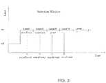
- the diagram of Fig. 3depicts a possible selection window for selecting the system state for switch 10 of the electrical appliance.
- switch 10When switch 10 is turned on for the first time, the user can select between different system states (e.g., shut-off time, temperature, power, etc.). If switch 10 is then turned off within a specific time interval, microprocessor 3 is set to execute the program of the selected system state, e.g. shut-off time. If the maximum value defined for this system state has been reached as the electrical appliance continues to be used, the switch emits an optical or acoustic signal, in this case an optical signal, i.e., LED 4 illuminates.
- system statese.g., shut-off time, temperature, power, etc.
- the usercan now choose whether to stay at this level. In this case he selects the reset mode by performing another switching operation of actuation element 6, for example, within a specified time interval.
- the usercan implement the change mode.
- the entire systemis reset by a further switching operation of actuation element 6 within a specified time interval.
- the time interval here between the change mode and the reset modeare different.
- another selection of the system statecan be effected as already described above.
- the maximum valuecan be determined by internal or external sensors for a specific electrical appliance, and optionally a determination can also be made whether this appliance is again ready to operate after reaching or exceeding the maximum value and is reset automatically.
- the inventionis thus not restricted to the exemplary embodiment.
- a bistable switch of an electrical appliancecan advantageously handle a plurality of functions.
- the actuation element of this switchis used both for turning on and off the electrical appliance as well as selecting a system state.
- the display on the switchcan display both functions.
- the reset function or a change to the system statecan also be implemented and indicated by this single actuation element.
- switch 10is shown mounted to a panel 12.
- Panel 12may be a control panel of the electrical appliance.
Landscapes
- Physics & Mathematics (AREA)
- General Physics & Mathematics (AREA)
- Engineering & Computer Science (AREA)
- Automation & Control Theory (AREA)
- Circuit Arrangement For Electric Light Sources In General (AREA)
- Push-Button Switches (AREA)
- Selective Calling Equipment (AREA)
- Keying Circuit Devices (AREA)
- Electric Stoves And Ranges (AREA)
Description
- This invention relates to a switch to control electrical appliances, in particular, domestic appliances.
- An electrical switch for controlling an electric appliance disclosed in
document DE 10 2007 014 174 A1 is in widespread use and has proven successful in practice. This switch has an external interface. A microprocessor disposed in the switch housing can be controlled through this external interface, and switching states or displays in the switch or the electrical appliance can be changed. Other switching arrangements are disclosed inUS2011/0057511 andUS8269376 . - In addition, a battery-operated electronic clock is disclosed in US Patent
US4316276 . A single push-button switch is provided on the clock housing, which switch can be operated by the user while adhering to a specific code whereby a signal sequence can be initiated. A desired time display is then selected by repeat actuation of the switch. In addition, a reset function is described. At least two counters for the counting operation are provided in the switch. For use of this switch in an electronic appliance an additional switch is required as an ON and OFF switch of the appliance. - Hence there is a desire for an improved electrical switch so as to enable it to be used for a plurality of applications without the need for additional cost in terms of technical components.
- Accordingly, in one aspect thereof, the present invention provides a switch for controlling an electrical appliance, comprising: a switch housing; a display; an actuation element projecting from the switch housing, which can activate at least one contact of the appliance when it is moved from an OFF position to an ON position, wherein changing the switching state changes an operating state of the electrical appliance and/or the display; a microprocessor disposed in the switch housing, by means of which the operating state of the appliance and/or the display can be changed by comparing a determined actual value with a stored maximum value for a system state; and means for selecting a maximum value from a set of selectable maximum values for a desired system state stored in the microprocessor, wherein one initial value and one maximum value each are stored in the microprocessor for each system state available for selection; such that when the electrical appliance is initially activated by the actuation element, the microprocessor initiates an identifier for different signals determined by the microprocessor which is displayed through the display, wherein the different signals correspond to different system states; and such that selection of one said different system state for the electrical appliance can be effected by actuating the actuation element, whilst a corresponding said signal associated with this system state is active at the display, wherein the associated maximum value for operating the electrical appliance also being set by the said actuation of the actuation element; wherein reaching or exceeding the maximum value for the selected system state can be indicated by a warning signal produced by the microprocessor.
- Preferably, an initial value for the operating duration or for the operating temperature, for example, a time 0 or temperature value, and also a maximum value, for example, a shut-off time or a maximum temperature, are stored in the microprocessor.
- Preferably, the actuation element is a rocker switch or a push-button switch, and an identifier of different signals can be initiated through the display, said identifier being determined by the microprocessor, when the electrical appliance is first turned on by moving the switch from the OFF position to the ON position.
- Preferably, in order to select the appropriate system state for the electrical appliance an activation of the microprocessor can be effected by moving the actuation element from the ON position to the OFF position, and specifically while the corresponding signal is active that is associated with this system state.
- Preferably, the identifier of different signals is reproduced by an optical or acoustic signal, preferably by an optical signal of the display.
- Preferably, different signals can be indicated by varying the length of the signal duration or by varying the frequency of reproduction, or by varying the color of optical signals.
- Preferably, reaching or exceeding the maximum value for the selected system state can also be indicated by an acoustic or optical warning signal.
- Preferably, moving the actuation element from its ON position to its OFF position can be effected while the warning signal for the reset mode or for the change mode is active, wherein the reset mode and/or the change mode can be indicated as different by acoustic or optical means, preferably different signals can be reproduced in different time windows.
- According to a second aspect, the present invention provides a method for controlling electrical appliances, comprising creating a sequential program for a microprocessor for a switch in accordance with the first aspect of the invention, comprising the steps of: defining different system states and defining initial values and maximum values for each system state; defining different signals; assigning one distinct signal to each system state; defining a warning signal for exceeding the maximum value; defining a reset mode and/or change mode; storing the sequential program and a control function in the microprocessor; starting the electrical appliance and optionally actuating the actuation element to activate the signals; and selecting one time a desired system state by actuating the actuation element while the relevant signal for the desired system state is active, whereby the maximum value is determined for operating the electrical appliance.
- Preferably, actuating the actuation element is effected within a specified time interval to perform the one-time selection of the desired system state.
- Preferably, the control function of the microprocessor is set to the initial value when the electrical appliance is first started, and each actuation of the actuation element is measured or counted by the microprocessor as the electrical appliance operates, and the attained actual value is compared with the maximum value.
- Preferably, activation of an optical or acoustic warning signal is effected by the microprocessor when the maximum value has been reached or exceeded.
- Preferably, different warning signals are indicated for the reset mode and for the change mode, and that either the reset mode or the change mode is effected by actuating the actuation element, and wherein the control function of the microprocessor is simultaneously set to the initial value.
- Preferably, a determination is made by a sensor after a warning signal has been activated whether conditions exist or do not exist for continued operation of the electrical appliance, whereupon a reset mode or change mode is automatically or manually initiated, or the appliance is shut off.
- Preferably, the microprocessor interacts with external sensors or thermal switches or current-measuring devices to determine the maximum value.
- According to a third aspect, the present invention provides use of the switch according to the first aspect, to determine a maximum operating temperature of an electrical appliance, to determine a maximum operating duration for an electrical appliance, or to determine a shut-off time for the stand-by mode of an electrical appliance.
- As with the switch disclosed in
document DE 10 2007 014 174 A1 , the switch according to the present invention is intended for use in electrical appliances. The switch has a switch housing that includes an associated actuation element which projects from the switch housing. Moving the actuation element, such as, for example, by a swivel, pressing, or sliding motion allows the actuation element to be moved from an OFF position to an ON position. In the ON position the actuation element, as with known switches, can activate at least one contact of the electrical appliance, thereby changing the operational state of the electrical appliance and/or a display. Display means are provided for this display, preferably directly on the actuation element. For example, this can be an LED light. A microprocessor is disposed in the switch housing. This microprocessor can be activated and it can compare current actual values transmitted to it with values that are stored in the microprocessor, specifically maximum values for a system state. The operating state of the appliance and/or a display can be changed by means of this comparison and corresponding evaluation. - This system state can relate, for example, to a shut-off time, operating duration, operating temperature, a maximum value for physical parameters such as temperature, time, amperage, voltage, volume level, etc.
- In the case of an appliance, the operating state of the appliance can also be changed whenever a maximum value is reached or has been exceeded. If, for example, the system state relates to an operating temperature and the maximum value is a maximum temperature, the microprocessor can effect a change in the operating state of the appliance in response to this maximum temperature having been exceeded by reducing, for example, the rpm for a rotational speed of an appliance or even shutting off the appliance.
- This system state can also relate to the stand-by mode of an electrical appliance. Different shut-off times can be associated with various stand-by times, the shut-off times being stored in the microprocessor as maximum values.
- In this invention all selectable system states are stored in the switch. Selection of an appropriate maximum value from among multiple possible maximum values for a desired system state is not effected externally but, as it were, internally. An initial value, a maximum value, and a corresponding program are stored in the microprocessor for all selectable system states, such as, for example, operating temperature or operating duration. The program initiates a specific identifier that can include various acoustic and/or optical signals - preferably optical signals of varying illumination time and/or illumination frequency and/or different colors which display various system states to the user. Selection of the desired system state is made when the electrical appliance is first turned on. Thus, for example, a specific system state can be set such as the shut-off time. To this end, the microprocessor initiates a specific signal sequence of different signals through the display. This can be effected simply by establishing an electrical connection between the appliance and a power source, i.e., the identifier is emitted whenever the appliance plug is simply plugged in. What is preferred, however, is an embodiment in which this identifier is initiated only after the initial actuation of the actuation element, i.e., the actuation element is turned on, the microprocessor initiates the identifier to select the system state where different optical or acoustic signals correspond to the identifier for different system states. Selection of the system state is then effected by again actuating the actuation element. This means the actuation element is actuated, e.g. turned off, during the identifier for a specific signal. As a result, precisely that system state is set which corresponds to this signal. Through this actuation the maximum value is determined for operating the electrical appliance for this system state, which value is used by the microprocessor by way of comparison as the maximum value when the appliance is operating.
- Once this system state is set, the electrical appliance can be operated by repeat actuation of the actuation element. A comparison of the actual value with the maximum value is performed by the microprocessor in response to each repeat actuation of the actuation element. The microprocessor can, for example, also have a counter function. A warning signal is produced by the microprocessor whenever a maximum value is reached. This can be an acoustic warning signal or an optical warning signal such as an LED flashing orange. An optical signal is preferred since the switch is already equipped with optical display means.
- If the system state relates, for example, to an operating duration, the warning signal of the microprocessor indicates that the previously set operating duration has been reached or exceeded. As a result the appliance can be shut off.
- If the system state of an electrical appliance relates, for example, to the operating temperature, the microprocessor indicates that the allowable temperature has been exceeded by a warning signal. The warning signal can then indicate that the electrical appliance will shut off automatically or will be moved to a different operating state within a specified time interval.
- Once the warning signal has been exceeded and the operator has been instructed about an action to be taken or the operating state of the electrical appliance has been changed by the microprocessor, the warning signal continues until the microprocessor is once again activated. A new initial value and/or system state can be reset by means of a reset mode and/or change mode. The activation can be effected by the actuation element of the switch. The reset mode causes the counter function in the microprocessor to be reset to the initial value of zero. If however the actuation element is switched off within a different time interval, this resets to the initial state of the appliance. A new system state can be set just as when the first start-up was effected.
- The reset mode in another embodiment can also be effected automatically by sensors - for example, thermal elements monitoring the operating temperature can transmit signals to the microprocessor, with the result that the microprocessor again displays a new initial value and thus again enables operation once the appliance has cooled down.
- The inventive embodiment of the switch for an electrical appliance supports saving energy in household appliances or other electrical appliances, and supports implementation of European Eco-Design Directive ErP. Switches according to the invention can be customized for use within a wide spectrum of applications. A desired system state (shut-off time, operating temperature, stand-by mode, etc.) can be selected by a switch for an electrical appliance, after which this switch can be used to operate the appliance and optionally for a reset mode and a change mode.
- A preferred embodiment of the invention will now be described, by way of example only, with reference to figures of the accompanying drawings. In the figures, identical structures, elements or parts that appear in more than one figure are generally labeled with a same reference numeral in all the figures in which they appear. Dimensions of components and features shown in the figures are generally chosen for convenience and clarity of presentation and are not necessarily shown to scale. The figures are listed below.
Fig. 1 is a side view of a switch according to the preferred embodiment of the present invention;Fig. 2 is a plan view of the switch ofFig. 1 , fitted to a panel; andFig. 3 is a diagram illustrating selection of possible switching states.- The following discussion describes the invention in more detail based on an exemplary embodiment. A switch is used for the electrical appliance, the switch being depicted in
Fig. 1 and Fig. 2 . Theactuation element 6 projects from thehousing 7 of theswitch 10, this actuation element being provided in the form of a rocker switch. Adisplay 4 is provided on thisactuation element 6 in the form of a light-emitting diode.Contacts 9, which are connected in the known manner to the electrical appliance, project from the bottom ofswitch 10. Amicroprocessor 3 is provided insidehousing 7 ofswitch 10.Microprocessor 3 includes switching electronics.Microprocessor 3 that is disposed inswitch housing 7 is appropriately programmed to control the electrical appliance, and the various selectable system states are stored there. A minimum and/or maximum value is furthermore defined for each system state. The diagram ofFig. 3 depicts a possible selection window for selecting the system state forswitch 10 of the electrical appliance. - When
switch 10 is turned on for the first time, the user can select between different system states (e.g., shut-off time, temperature, power, etc.). Ifswitch 10 is then turned off within a specific time interval,microprocessor 3 is set to execute the program of the selected system state, e.g. shut-off time. If the maximum value defined for this system state has been reached as the electrical appliance continues to be used, the switch emits an optical or acoustic signal, in this case an optical signal, i.e.,LED 4 illuminates. - The user can now choose whether to stay at this level. In this case he selects the reset mode by performing another switching operation of
actuation element 6, for example, within a specified time interval. - If a different system state is to be selected such as e.g., the temperature, the user can implement the change mode. In this case the entire system is reset by a further switching operation of
actuation element 6 within a specified time interval. The time interval here between the change mode and the reset mode are different. After the entire system is reset, another selection of the system state can be effected as already described above. - All of the above-mentioned actions are programmed accordingly in
microprocessor 3. In addition, above-describedswitch 10 according to the invention can also be used to set other system states that have not been mentioned. Both the rocker switch shown inFig. 1 as well as a push-button switch or other electrical switch can be used for this purpose. - In addition, the maximum value can be determined by internal or external sensors for a specific electrical appliance, and optionally a determination can also be made whether this appliance is again ready to operate after reaching or exceeding the maximum value and is reset automatically. The invention is thus not restricted to the exemplary embodiment.
- A bistable switch of an electrical appliance can advantageously handle a plurality of functions. The actuation element of this switch is used both for turning on and off the electrical appliance as well as selecting a system state. The display on the switch can display both functions. In addition, the reset function or a change to the system state can also be implemented and indicated by this single actuation element.
- In
Fig. 2 , switch 10 is shown mounted to apanel 12.Panel 12 may be a control panel of the electrical appliance. - In the description and claims of the present application, each of the verbs "comprise", "include", "contain" and "have", and variations thereof, are used in an inclusive sense, to specify the presence of the stated item or feature but do not preclude the presence of additional items or features.
- It is appreciated that certain features of the invention, which are, for clarity, described in the context of separate embodiments, may also be provided in combination in a single embodiment. Conversely, various features of the invention which are, for brevity, described in the context of a single embodiment, may also be provided separately or in any suitable sub-combination.
- The embodiments described above are provided by way of example only, and various other modifications will be apparent to persons skilled in the field without departing from the scope of the invention as defined by the appended claims.
Claims (15)
- Switch for controlling an electrical appliance, comprising:a switch housing;a display;an actuation element (6) projecting from the switch housing (7), which can activate at least one contact of the appliance when it is moved from an OFF position to an ON position, wherein changing the switching state changes an operating state of the electrical appliance and/or the display;a microprocessor (3) disposed in the switch housing (7), by means of which the operating state of the appliance and/or the display can be changed by comparing a determined actual value with a stored maximum value for a system state;means for selecting a maximum value from a set of selectable maximum values for a desired system state stored in the microprocessor (3),characterized in that one initial value and one maximum value each are stored in the microprocessor (3) for all system states available for selection;such that, when the electrical appliance is initially activated by the actuation element (6), the microprocessor (3) initiates an identifier for different signals determined by the microprocessor (3) which is displayed through the display (4), wherein the different signals correspond to different system states;and such that selection of one said different system state for the electrical appliance can be effected by actuating the actuation element (6), whilst a corresponding said signal associated with this system state is active at the display (4), wherein the associated maximum value for operating the electrical appliance also being set by the said actuation of the actuation element (6);wherein reaching or exceeding the maximum value for the selected system state can be indicated by a warning signal produced by the microprocessor (3).
- Switch according to Claim 1, wherein an initial value for the operating duration or for the operating temperature, for example, a time 0 or temperature value, and also a maximum value, for example, a shut-off time or a maximum temperature, are stored in the microprocessor.
- Switch according to Claim 1 or 2, wherein the actuation element (6) is a rocker switch or a push-button switch, and an identifier of different signals can be initiated through the display (4), said identifier being determined by the microprocessor (3), when the electrical appliance is first turned on by moving the switch from the OFF position to the ON position.
- Switch according to any one of Claims 1 through 3, wherein in order to select the appropriate system state for the electrical appliance an activation of the microprocessor (3) can be effected by moving the actuation element (6) from the ON position to the OFF position, and specifically while the corresponding signal is active that is associated with this system state.
- Switch according to any one of Claims 1 through 4, wherein the identifier of different signals is reproduced by an optical or acoustic signal, preferably by an optical signal of the display (4).
- Switch according to Claim 5, wherein different signals can be indicated by varying the length of the signal duration or by varying the frequency of reproduction, or by varying the color of optical signals.
- Switch according to any one of Claims 1 through 6, wherein reaching or exceeding the maximum value for the selected system state can also be indicated by an acoustic or optical warning signal.
- Switch according to any one of Claims 1 through 7, wherein moving the actuation element (6) from its ON position to its OFF position can be effected while the warning signal for the reset mode or for the change mode is active, wherein the reset mode and/or the change mode can be indicated as different by acoustic or optical means, preferably different signals can be reproduced in different time windows.
- Method for controlling electrical appliances, comprising the steps of:creating a sequential program for a microprocessor (3) disposed in a switch as claimed in any one of the preceding claims, comprising:defining different system states and defining initial values and maximum values for each system state:defining different signals;assigning one distinct signal to each system state;defining a warning signal for exceeding the maximum value;defining a reset mode and/or change mode;storing the sequential program and a control function in the microprocessor;starting the electrical appliance and optionally actuating the actuation element (6) to activate the signals; andselecting one time a desired system state by actuating the actuation element (6) while the relevant signal for the desired system state is active, whereby the maximum value is determined for operating the electrical appliance.
- Method according to Claim 9, wherein actuating the actuation element (6) is effected within a specified time interval to perform the one-time selection of the desired system state.
- Method according to Claim 9 or 10, wherein the control function of the microprocessor is set to the initial value when the electrical appliance is first started, and each actuation of the actuation element (6) is measured or counted by the microprocessor as the electrical appliance operates, and the attained actual value is compared with the maximum value.
- Method according to any one of Claims 9 through 11, wherein activation of an optical or acoustic warning signal is effected by the microprocessor when the maximum value has been reached or exceeded.
- Method according to any one of Claims 9 through 12, wherein different warning signals are indicated for the reset mode and for the change mode, and that either the reset mode or the change mode is effected by actuating the actuation element (6), and wherein the control function of the microprocessor (8) is simultaneously set to the initial value.
- Method according to any one of Claims 9 through 13, wherein a determination is made by a sensor after a warning signal has been activated whether conditions exist or do not exist for continued operation of the electrical appliance, whereupon a reset mode or change mode is automatically or manually initiated, or the appliance is shut off.
- Method according to any one of Claims 9 through 13, wherein the microprocessor interacts with external sensors or thermal switches or current-measuring devices to determine the maximum value.
Applications Claiming Priority (1)
| Application Number | Priority Date | Filing Date | Title |
|---|---|---|---|
| DE102014108158 | 2014-06-10 |
Publications (2)
| Publication Number | Publication Date |
|---|---|
| EP2955734A1 EP2955734A1 (en) | 2015-12-16 |
| EP2955734B1true EP2955734B1 (en) | 2018-12-26 |
Family
ID=53385532
Family Applications (1)
| Application Number | Title | Priority Date | Filing Date |
|---|---|---|---|
| EP15171229.6AActiveEP2955734B1 (en) | 2014-06-10 | 2015-06-09 | Switch |
Country Status (5)
| Country | Link |
|---|---|
| US (1) | US10002723B2 (en) |
| EP (1) | EP2955734B1 (en) |
| JP (1) | JP6591793B2 (en) |
| CN (1) | CN105182806B (en) |
| DE (1) | DE102015108771A1 (en) |
Families Citing this family (3)
| Publication number | Priority date | Publication date | Assignee | Title |
|---|---|---|---|---|
| DE102016101017A1 (en)* | 2016-01-21 | 2017-07-27 | Johnson Electric Germany GmbH & Co. KG | Electric rocker switch |
| CN106057550A (en)* | 2016-07-17 | 2016-10-26 | 吉林省德沃尔机电有限公司 | Integrated rocker switch |
| US11805902B2 (en) | 2019-04-25 | 2023-11-07 | Ergotron, Inc. | Height adjustable workstation with zero idle power |
Family Cites Families (32)
| Publication number | Priority date | Publication date | Assignee | Title |
|---|---|---|---|---|
| US4316276A (en) | 1974-08-15 | 1982-02-16 | Bulova Watch Company, Inc. | Key-operated solid-state timepieces |
| US4500795A (en)* | 1982-09-30 | 1985-02-19 | Hochstein Peter A | Electrical timing control switch |
| US4672233A (en)* | 1985-06-24 | 1987-06-09 | Emhart Industries, Inc. | Controller with dual function switch |
| JPH0592791U (en)* | 1992-05-15 | 1993-12-17 | リズム時計工業株式会社 | Function selection mechanism of multifunctional clock |
| JPH06175185A (en)* | 1992-12-07 | 1994-06-24 | Fuji Photo Optical Co Ltd | Abnormality detecting device for camera |
| US6039702A (en)* | 1996-08-02 | 2000-03-21 | Jb Research, Inc. | Microcontroller based massage system |
| US6114839A (en)* | 1997-11-20 | 2000-09-05 | Hitachi Koki Co., Ltd. | Battery charging apparatus with error detection |
| US6984900B1 (en)* | 1998-10-09 | 2006-01-10 | Azoteq (Pty) Ltd. | Intelligent electrical switch |
| JP2001100893A (en)* | 1999-09-29 | 2001-04-13 | Fujitsu Ten Ltd | Switch input device |
| JP5024977B2 (en)* | 2001-03-15 | 2012-09-12 | 株式会社キーエンス | Photoelectric switch |
| US6765477B2 (en)* | 2002-05-01 | 2004-07-20 | Edwards Systems Technology, Inc. | Apparatus and method for activating a non-contact switch fire alarm pull station |
| PL203170B1 (en)* | 2002-07-01 | 2009-09-30 | Advanced Digital Broadcast Ltd | System designed to detect actuation of microprocessor operation monitoring internal system and method of zeroing microprocessor system equipped with a system detecting actuation of internal monitoring system |
| JP4628172B2 (en)* | 2005-04-28 | 2011-02-09 | セイコーインスツル株式会社 | Boost DC-DC and semiconductor device having boost DC-DC |
| US20070215441A1 (en)* | 2006-03-14 | 2007-09-20 | Shary Nassimi | Timed Light Switch |
| US7304464B2 (en)* | 2006-03-15 | 2007-12-04 | Micrel, Inc. | Switching voltage regulator with low current trickle mode |
| KR20080041040A (en)* | 2006-11-06 | 2008-05-09 | 삼성전자주식회사 | Integrated circuit card with improved stability |
| DE202007004499U1 (en) | 2007-03-24 | 2008-08-07 | Saia-Burgess Halver Gmbh | Electric switch |
| DE102007014174B4 (en) | 2007-03-24 | 2021-05-12 | Johnson Electric Germany GmbH & Co. KG | Electric switch |
| CN201119069Y (en)* | 2007-11-13 | 2008-09-17 | 昆明理工大学 | Intelligent control device for classroom lighting and air conditioning |
| CN101436319A (en)* | 2007-11-16 | 2009-05-20 | 周振龙 | Intelligent control method for electrical switch |
| CN101361630A (en)* | 2008-09-29 | 2009-02-11 | 宜烽精机股份有限公司 | Electric control device of tea making machine |
| FR2949916B1 (en)* | 2009-09-08 | 2016-07-22 | Jerome Gilbert | DEVICE FOR DISCONNECTING AT LEAST ONE APPARATUS FROM THE ELECTRICAL NETWORK, WHICH OFFERS AT LEAST ONE OPERATING MODE IN DEROGATION, CONFIGURABLE DEVICE, SYSTEM AND CONFIGURATION METHOD. |
| CN201689357U (en)* | 2009-11-27 | 2010-12-29 | 深圳和而泰智能控制股份有限公司 | Device capable of realizing zero standby power consumption |
| US20120239791A1 (en)* | 2011-03-16 | 2012-09-20 | Seiko Epson Corporation | Network System, Network Configuration Method, And Network Configuration Device |
| US8269376B1 (en)* | 2011-09-06 | 2012-09-18 | Elbex Video Ltd. | Method and apparatus for switching on-off a group or all lights or appliances of premises |
| TW201344427A (en)* | 2012-04-27 | 2013-11-01 | Hon Hai Prec Ind Co Ltd | System and method of monitoring server |
| WO2013183063A2 (en)* | 2012-06-01 | 2013-12-12 | Mahindra & Mahindra Limited | Power-economy mode control system for a vehicle |
| CN203169401U (en)* | 2013-01-24 | 2013-09-04 | 陈金森 | Pain trigger point physical therapy method therapeutic apparatus |
| DE102013107177A1 (en)* | 2013-07-08 | 2015-01-08 | Johnson Electric Germany GmbH & Co. KG | descaling |
| CN103550029A (en)* | 2013-09-26 | 2014-02-05 | 三维医疗科技江苏股份有限公司 | Multifunctional eyeshade |
| US9500366B2 (en)* | 2013-12-05 | 2016-11-22 | International Controls And Measurements Corp. | Furnace control with safety circuit and non-volatile memory |
| SG2013094115A (en)* | 2013-12-19 | 2015-07-30 | Schneider Electric South East Asia Hq Pte Ltd | Trigger actuator for a switching device |
- 2015
- 2015-06-03DEDE102015108771.5Apatent/DE102015108771A1/ennot_activeWithdrawn
- 2015-06-09CNCN201510314336.XApatent/CN105182806B/enactiveActive
- 2015-06-09EPEP15171229.6Apatent/EP2955734B1/enactiveActive
- 2015-06-10USUS14/736,043patent/US10002723B2/enactiveActive
- 2015-06-10JPJP2015117286Apatent/JP6591793B2/enactiveActive
Non-Patent Citations (1)
| Title |
|---|
| None* |
Also Published As
| Publication number | Publication date |
|---|---|
| JP6591793B2 (en) | 2019-10-16 |
| US20150357130A1 (en) | 2015-12-10 |
| DE102015108771A1 (en) | 2015-12-17 |
| JP2016001874A (en) | 2016-01-07 |
| CN105182806B (en) | 2020-09-15 |
| CN105182806A (en) | 2015-12-23 |
| US10002723B2 (en) | 2018-06-19 |
| EP2955734A1 (en) | 2015-12-16 |
Similar Documents
| Publication | Publication Date | Title |
|---|---|---|
| CN108227824B (en) | Control knob for controlling operation of a machine | |
| CN211454410U (en) | Control knob for controlling operation of a machine | |
| CN107340723B (en) | Mode switching method and device of intelligent electrical appliance | |
| KR20100080337A (en) | Hair dryer | |
| EP2955734B1 (en) | Switch | |
| ITMI20020053A1 (en) | CONTROL DEVICE OF A SIMPLE MANUFACTURING HOUSEHOLD APPLIANCE | |
| CN107198433B (en) | Function menu display method and device and electric cooker | |
| KR20060123084A (en) | Cooking devices and controls for displaying information | |
| CN109710098B (en) | Touch button with display screen and household appliance | |
| US20150018986A1 (en) | Electrical switch assembly | |
| CN205568652U (en) | Electric cooking ware | |
| EP3038072B1 (en) | Electric product | |
| US10782027B2 (en) | Cooking appliance with user-selectable sear feature | |
| JPH0676946A (en) | Collective heating device | |
| CN104080248B (en) | Display control method and device, and cooking appliance | |
| KR20120071843A (en) | Power concent apparatus for interlocking power status of electronic device and control method thereof | |
| JP6080697B2 (en) | Induction heating cooker | |
| JP2007227995A (en) | Remote controller and remote control system | |
| JP6674234B2 (en) | Dishwasher | |
| CN204797625U (en) | Oven and state indicating circuit thereof | |
| IT202100028397A1 (en) | “INTELLIGENT KNOB FOR HOUSEHOLD APPLIANCES” | |
| JP2008130520A (en) | Equipment control device | |
| KR0137858B1 (en) | Set operation method of one-key remote control | |
| TWM518434U (en) | Remote adapter and electronic device | |
| KR200186599Y1 (en) | Device for cooking display in induction heating cooker |
Legal Events
| Date | Code | Title | Description |
|---|---|---|---|
| PUAI | Public reference made under article 153(3) epc to a published international application that has entered the european phase | Free format text:ORIGINAL CODE: 0009012 | |
| AK | Designated contracting states | Kind code of ref document:A1 Designated state(s):AL AT BE BG CH CY CZ DE DK EE ES FI FR GB GR HR HU IE IS IT LI LT LU LV MC MK MT NL NO PL PT RO RS SE SI SK SM TR | |
| AX | Request for extension of the european patent | Extension state:BA ME | |
| 17P | Request for examination filed | Effective date:20160616 | |
| RBV | Designated contracting states (corrected) | Designated state(s):AL AT BE BG CH CY CZ DE DK EE ES FI FR GB GR HR HU IE IS IT LI LT LU LV MC MK MT NL NO PL PT RO RS SE SI SK SM TR | |
| GRAP | Despatch of communication of intention to grant a patent | Free format text:ORIGINAL CODE: EPIDOSNIGR1 | |
| STAA | Information on the status of an ep patent application or granted ep patent | Free format text:STATUS: GRANT OF PATENT IS INTENDED | |
| RIC1 | Information provided on ipc code assigned before grant | Ipc:G01R 31/327 20060101ALN20180712BHEP Ipc:G06F 1/26 20060101ALN20180712BHEP Ipc:H01H 9/16 20060101AFI20180712BHEP | |
| RIC1 | Information provided on ipc code assigned before grant | Ipc:G06F 1/26 20060101ALN20180718BHEP Ipc:H01H 9/16 20060101AFI20180718BHEP Ipc:G01R 31/327 20060101ALN20180718BHEP | |
| INTG | Intention to grant announced | Effective date:20180731 | |
| GRAS | Grant fee paid | Free format text:ORIGINAL CODE: EPIDOSNIGR3 | |
| GRAA | (expected) grant | Free format text:ORIGINAL CODE: 0009210 | |
| STAA | Information on the status of an ep patent application or granted ep patent | Free format text:STATUS: THE PATENT HAS BEEN GRANTED | |
| RAP1 | Party data changed (applicant data changed or rights of an application transferred) | Owner name:JOHNSON ELECTRIC INTERNATIONAL AG | |
| AK | Designated contracting states | Kind code of ref document:B1 Designated state(s):AL AT BE BG CH CY CZ DE DK EE ES FI FR GB GR HR HU IE IS IT LI LT LU LV MC MK MT NL NO PL PT RO RS SE SI SK SM TR | |
| REG | Reference to a national code | Ref country code:GB Ref legal event code:FG4D | |
| REG | Reference to a national code | Ref country code:CH Ref legal event code:EP | |
| REG | Reference to a national code | Ref country code:AT Ref legal event code:REF Ref document number:1082570 Country of ref document:AT Kind code of ref document:T Effective date:20190115 | |
| REG | Reference to a national code | Ref country code:DE Ref legal event code:R096 Ref document number:602015022130 Country of ref document:DE | |
| REG | Reference to a national code | Ref country code:IE Ref legal event code:FG4D | |
| PG25 | Lapsed in a contracting state [announced via postgrant information from national office to epo] | Ref country code:NO Free format text:LAPSE BECAUSE OF FAILURE TO SUBMIT A TRANSLATION OF THE DESCRIPTION OR TO PAY THE FEE WITHIN THE PRESCRIBED TIME-LIMIT Effective date:20190326 Ref country code:LT Free format text:LAPSE BECAUSE OF FAILURE TO SUBMIT A TRANSLATION OF THE DESCRIPTION OR TO PAY THE FEE WITHIN THE PRESCRIBED TIME-LIMIT Effective date:20181226 Ref country code:LV Free format text:LAPSE BECAUSE OF FAILURE TO SUBMIT A TRANSLATION OF THE DESCRIPTION OR TO PAY THE FEE WITHIN THE PRESCRIBED TIME-LIMIT Effective date:20181226 Ref country code:FI Free format text:LAPSE BECAUSE OF FAILURE TO SUBMIT A TRANSLATION OF THE DESCRIPTION OR TO PAY THE FEE WITHIN THE PRESCRIBED TIME-LIMIT Effective date:20181226 Ref country code:BG Free format text:LAPSE BECAUSE OF FAILURE TO SUBMIT A TRANSLATION OF THE DESCRIPTION OR TO PAY THE FEE WITHIN THE PRESCRIBED TIME-LIMIT Effective date:20190326 Ref country code:HR Free format text:LAPSE BECAUSE OF FAILURE TO SUBMIT A TRANSLATION OF THE DESCRIPTION OR TO PAY THE FEE WITHIN THE PRESCRIBED TIME-LIMIT Effective date:20181226 | |
| REG | Reference to a national code | Ref country code:NL Ref legal event code:MP Effective date:20181226 | |
| REG | Reference to a national code | Ref country code:LT Ref legal event code:MG4D | |
| PG25 | Lapsed in a contracting state [announced via postgrant information from national office to epo] | Ref country code:GR Free format text:LAPSE BECAUSE OF FAILURE TO SUBMIT A TRANSLATION OF THE DESCRIPTION OR TO PAY THE FEE WITHIN THE PRESCRIBED TIME-LIMIT Effective date:20190327 Ref country code:SE Free format text:LAPSE BECAUSE OF FAILURE TO SUBMIT A TRANSLATION OF THE DESCRIPTION OR TO PAY THE FEE WITHIN THE PRESCRIBED TIME-LIMIT Effective date:20181226 Ref country code:AL Free format text:LAPSE BECAUSE OF FAILURE TO SUBMIT A TRANSLATION OF THE DESCRIPTION OR TO PAY THE FEE WITHIN THE PRESCRIBED TIME-LIMIT Effective date:20181226 Ref country code:RS Free format text:LAPSE BECAUSE OF FAILURE TO SUBMIT A TRANSLATION OF THE DESCRIPTION OR TO PAY THE FEE WITHIN THE PRESCRIBED TIME-LIMIT Effective date:20181226 | |
| REG | Reference to a national code | Ref country code:AT Ref legal event code:MK05 Ref document number:1082570 Country of ref document:AT Kind code of ref document:T Effective date:20181226 | |
| PG25 | Lapsed in a contracting state [announced via postgrant information from national office to epo] | Ref country code:NL Free format text:LAPSE BECAUSE OF FAILURE TO SUBMIT A TRANSLATION OF THE DESCRIPTION OR TO PAY THE FEE WITHIN THE PRESCRIBED TIME-LIMIT Effective date:20181226 | |
| PG25 | Lapsed in a contracting state [announced via postgrant information from national office to epo] | Ref country code:ES Free format text:LAPSE BECAUSE OF FAILURE TO SUBMIT A TRANSLATION OF THE DESCRIPTION OR TO PAY THE FEE WITHIN THE PRESCRIBED TIME-LIMIT Effective date:20181226 Ref country code:PL Free format text:LAPSE BECAUSE OF FAILURE TO SUBMIT A TRANSLATION OF THE DESCRIPTION OR TO PAY THE FEE WITHIN THE PRESCRIBED TIME-LIMIT Effective date:20181226 Ref country code:PT Free format text:LAPSE BECAUSE OF FAILURE TO SUBMIT A TRANSLATION OF THE DESCRIPTION OR TO PAY THE FEE WITHIN THE PRESCRIBED TIME-LIMIT Effective date:20190426 Ref country code:CZ Free format text:LAPSE BECAUSE OF FAILURE TO SUBMIT A TRANSLATION OF THE DESCRIPTION OR TO PAY THE FEE WITHIN THE PRESCRIBED TIME-LIMIT Effective date:20181226 | |
| PG25 | Lapsed in a contracting state [announced via postgrant information from national office to epo] | Ref country code:RO Free format text:LAPSE BECAUSE OF FAILURE TO SUBMIT A TRANSLATION OF THE DESCRIPTION OR TO PAY THE FEE WITHIN THE PRESCRIBED TIME-LIMIT Effective date:20181226 Ref country code:IS Free format text:LAPSE BECAUSE OF FAILURE TO SUBMIT A TRANSLATION OF THE DESCRIPTION OR TO PAY THE FEE WITHIN THE PRESCRIBED TIME-LIMIT Effective date:20190426 Ref country code:SM Free format text:LAPSE BECAUSE OF FAILURE TO SUBMIT A TRANSLATION OF THE DESCRIPTION OR TO PAY THE FEE WITHIN THE PRESCRIBED TIME-LIMIT Effective date:20181226 Ref country code:EE Free format text:LAPSE BECAUSE OF FAILURE TO SUBMIT A TRANSLATION OF THE DESCRIPTION OR TO PAY THE FEE WITHIN THE PRESCRIBED TIME-LIMIT Effective date:20181226 Ref country code:SK Free format text:LAPSE BECAUSE OF FAILURE TO SUBMIT A TRANSLATION OF THE DESCRIPTION OR TO PAY THE FEE WITHIN THE PRESCRIBED TIME-LIMIT Effective date:20181226 | |
| REG | Reference to a national code | Ref country code:DE Ref legal event code:R097 Ref document number:602015022130 Country of ref document:DE | |
| PG25 | Lapsed in a contracting state [announced via postgrant information from national office to epo] | Ref country code:DK Free format text:LAPSE BECAUSE OF FAILURE TO SUBMIT A TRANSLATION OF THE DESCRIPTION OR TO PAY THE FEE WITHIN THE PRESCRIBED TIME-LIMIT Effective date:20181226 Ref country code:AT Free format text:LAPSE BECAUSE OF FAILURE TO SUBMIT A TRANSLATION OF THE DESCRIPTION OR TO PAY THE FEE WITHIN THE PRESCRIBED TIME-LIMIT Effective date:20181226 | |
| PLBE | No opposition filed within time limit | Free format text:ORIGINAL CODE: 0009261 | |
| STAA | Information on the status of an ep patent application or granted ep patent | Free format text:STATUS: NO OPPOSITION FILED WITHIN TIME LIMIT | |
| 26N | No opposition filed | Effective date:20190927 | |
| PG25 | Lapsed in a contracting state [announced via postgrant information from national office to epo] | Ref country code:MC Free format text:LAPSE BECAUSE OF FAILURE TO SUBMIT A TRANSLATION OF THE DESCRIPTION OR TO PAY THE FEE WITHIN THE PRESCRIBED TIME-LIMIT Effective date:20181226 | |
| REG | Reference to a national code | Ref country code:CH Ref legal event code:PL | |
| GBPC | Gb: european patent ceased through non-payment of renewal fee | Effective date:20190609 | |
| PG25 | Lapsed in a contracting state [announced via postgrant information from national office to epo] | Ref country code:SI Free format text:LAPSE BECAUSE OF FAILURE TO SUBMIT A TRANSLATION OF THE DESCRIPTION OR TO PAY THE FEE WITHIN THE PRESCRIBED TIME-LIMIT Effective date:20181226 | |
| REG | Reference to a national code | Ref country code:BE Ref legal event code:MM Effective date:20190630 | |
| PG25 | Lapsed in a contracting state [announced via postgrant information from national office to epo] | Ref country code:TR Free format text:LAPSE BECAUSE OF FAILURE TO SUBMIT A TRANSLATION OF THE DESCRIPTION OR TO PAY THE FEE WITHIN THE PRESCRIBED TIME-LIMIT Effective date:20181226 | |
| PG25 | Lapsed in a contracting state [announced via postgrant information from national office to epo] | Ref country code:IE Free format text:LAPSE BECAUSE OF NON-PAYMENT OF DUE FEES Effective date:20190609 Ref country code:GB Free format text:LAPSE BECAUSE OF NON-PAYMENT OF DUE FEES Effective date:20190609 | |
| PG25 | Lapsed in a contracting state [announced via postgrant information from national office to epo] | Ref country code:BE Free format text:LAPSE BECAUSE OF NON-PAYMENT OF DUE FEES Effective date:20190630 Ref country code:CH Free format text:LAPSE BECAUSE OF NON-PAYMENT OF DUE FEES Effective date:20190630 Ref country code:LI Free format text:LAPSE BECAUSE OF NON-PAYMENT OF DUE FEES Effective date:20190630 Ref country code:LU Free format text:LAPSE BECAUSE OF NON-PAYMENT OF DUE FEES Effective date:20190609 | |
| PG25 | Lapsed in a contracting state [announced via postgrant information from national office to epo] | Ref country code:FR Free format text:LAPSE BECAUSE OF NON-PAYMENT OF DUE FEES Effective date:20190630 | |
| PG25 | Lapsed in a contracting state [announced via postgrant information from national office to epo] | Ref country code:CY Free format text:LAPSE BECAUSE OF FAILURE TO SUBMIT A TRANSLATION OF THE DESCRIPTION OR TO PAY THE FEE WITHIN THE PRESCRIBED TIME-LIMIT Effective date:20181226 | |
| PG25 | Lapsed in a contracting state [announced via postgrant information from national office to epo] | Ref country code:MT Free format text:LAPSE BECAUSE OF FAILURE TO SUBMIT A TRANSLATION OF THE DESCRIPTION OR TO PAY THE FEE WITHIN THE PRESCRIBED TIME-LIMIT Effective date:20181226 Ref country code:HU Free format text:LAPSE BECAUSE OF FAILURE TO SUBMIT A TRANSLATION OF THE DESCRIPTION OR TO PAY THE FEE WITHIN THE PRESCRIBED TIME-LIMIT; INVALID AB INITIO Effective date:20150609 | |
| PG25 | Lapsed in a contracting state [announced via postgrant information from national office to epo] | Ref country code:MK Free format text:LAPSE BECAUSE OF FAILURE TO SUBMIT A TRANSLATION OF THE DESCRIPTION OR TO PAY THE FEE WITHIN THE PRESCRIBED TIME-LIMIT Effective date:20181226 | |
| REG | Reference to a national code | Ref country code:DE Ref legal event code:R084 Ref document number:602015022130 Country of ref document:DE | |
| P01 | Opt-out of the competence of the unified patent court (upc) registered | Effective date:20230628 | |
| PGFP | Annual fee paid to national office [announced via postgrant information from national office to epo] | Ref country code:IT Payment date:20240619 Year of fee payment:10 | |
| PGFP | Annual fee paid to national office [announced via postgrant information from national office to epo] | Ref country code:DE Payment date:20250626 Year of fee payment:11 |