EP2955461A1 - Improved solar receiver configuration - Google Patents
Improved solar receiver configurationDownload PDFInfo
- Publication number
- EP2955461A1 EP2955461A1EP15171232.0AEP15171232AEP2955461A1EP 2955461 A1EP2955461 A1EP 2955461A1EP 15171232 AEP15171232 AEP 15171232AEP 2955461 A1EP2955461 A1EP 2955461A1
- Authority
- EP
- European Patent Office
- Prior art keywords
- panel
- headers
- header
- panels
- solar receiver
- Prior art date
- Legal status (The legal status is an assumption and is not a legal conclusion. Google has not performed a legal analysis and makes no representation as to the accuracy of the status listed.)
- Granted
Links
Images


Classifications
- F—MECHANICAL ENGINEERING; LIGHTING; HEATING; WEAPONS; BLASTING
- F24—HEATING; RANGES; VENTILATING
- F24S—SOLAR HEAT COLLECTORS; SOLAR HEAT SYSTEMS
- F24S10/00—Solar heat collectors using working fluids
- F24S10/70—Solar heat collectors using working fluids the working fluids being conveyed through tubular absorbing conduits
- F24S10/72—Solar heat collectors using working fluids the working fluids being conveyed through tubular absorbing conduits the tubular conduits being integrated in a block; the tubular conduits touching each other
- F—MECHANICAL ENGINEERING; LIGHTING; HEATING; WEAPONS; BLASTING
- F24—HEATING; RANGES; VENTILATING
- F24S—SOLAR HEAT COLLECTORS; SOLAR HEAT SYSTEMS
- F24S20/00—Solar heat collectors specially adapted for particular uses or environments
- F24S20/20—Solar heat collectors for receiving concentrated solar energy, e.g. receivers for solar power plants
- F—MECHANICAL ENGINEERING; LIGHTING; HEATING; WEAPONS; BLASTING
- F24—HEATING; RANGES; VENTILATING
- F24S—SOLAR HEAT COLLECTORS; SOLAR HEAT SYSTEMS
- F24S80/00—Details, accessories or component parts of solar heat collectors not provided for in groups F24S10/00-F24S70/00
- F24S80/30—Arrangements for connecting the fluid circuits of solar collectors with each other or with other components, e.g. pipe connections; Fluid distributing means, e.g. headers
- F—MECHANICAL ENGINEERING; LIGHTING; HEATING; WEAPONS; BLASTING
- F24—HEATING; RANGES; VENTILATING
- F24S—SOLAR HEAT COLLECTORS; SOLAR HEAT SYSTEMS
- F24S10/00—Solar heat collectors using working fluids
- F24S10/70—Solar heat collectors using working fluids the working fluids being conveyed through tubular absorbing conduits
- F24S10/74—Solar heat collectors using working fluids the working fluids being conveyed through tubular absorbing conduits the tubular conduits are not fixed to heat absorbing plates and are not touching each other
- F24S10/742—Solar heat collectors using working fluids the working fluids being conveyed through tubular absorbing conduits the tubular conduits are not fixed to heat absorbing plates and are not touching each other the conduits being parallel to each other
- Y—GENERAL TAGGING OF NEW TECHNOLOGICAL DEVELOPMENTS; GENERAL TAGGING OF CROSS-SECTIONAL TECHNOLOGIES SPANNING OVER SEVERAL SECTIONS OF THE IPC; TECHNICAL SUBJECTS COVERED BY FORMER USPC CROSS-REFERENCE ART COLLECTIONS [XRACs] AND DIGESTS
- Y02—TECHNOLOGIES OR APPLICATIONS FOR MITIGATION OR ADAPTATION AGAINST CLIMATE CHANGE
- Y02E—REDUCTION OF GREENHOUSE GAS [GHG] EMISSIONS, RELATED TO ENERGY GENERATION, TRANSMISSION OR DISTRIBUTION
- Y02E10/00—Energy generation through renewable energy sources
- Y02E10/40—Solar thermal energy, e.g. solar towers
- Y02E10/44—Heat exchange systems
Definitions
- the present inventionrelates to a solar central receiver of a concentrated power tower plant, and, more particularly, to an improved panel and header arrangement and orientation of panels comprising a heat transfer surface for a solar central receiver.
- a large field of heliostatsis arranged around a solar central receiver (solar receiver) placed on a tower of substantial height, where the heliostats focus direct sunlight on to the solar receiver to provide heat to a heat transfer fluid, which is applied to produce steam to run a turbine and extract work in order to produce electricity.
- the solar receivergenerally includes various vertical panels, each having fluid-carrying vertical tubes arranged between horizontally disposed headers for distribution of fluid into the tubes. Tube panel arrangements for configuring the solar receiver are important to effectively utilize solar flux without any spillage or leakage (solar energy not received on the heat transfer surface so as to be absorbed into the heat transfer medium) and proper functioning of the solar receiver.
- each panel of the heat transfer surfacecomprises a flat vertical tube panel between inlet and outlet headers, wherein the headers are positioned in a plane common to the centerline of the tube panel surface.
- the adjacent panels of the solar receiverare positioned with spacing therebetween the edge tubes of adjacent panels to accommodate the length of the panel headers.
- the size of the spacing between panels' edge tubesis such that the thermal expansion of the panels is insufficient to close the spacing between panels' edge tubes, resulting in spillage or leakage of solar flux, possibly causing damage of solar receiver's internal components.
- the present disclosuredescribes a solar receiver with an improved header and panel design that will be presented in the following simplified summary to provide a basic understanding of one or more aspects of the disclosure that are intended to overcome the discussed drawbacks, but to include all advantages thereof, along with providing some additional advantages.
- This summaryis not an extensive overview of the disclosure. It is intended to neither identify key or critical elements of the disclosure, nor to delineate the scope of the present disclosure. Rather, the sole purpose of this summary is to present some concepts of the disclosure, its aspects and advantages in a simplified form as a prelude to the more detailed description that is presented hereinafter.
- An object of the present disclosureis to describe a solar receiver with improved panel and header design, which may be capable of maintaining a constant spacing of the panel arrangements while balancing other constraints, such as, minimum receiver diameter, ease of manufacturing and erection, full drainability and reduced bending stress. Further, an object of the present disclosure is to describe a solar receiver with improved panel and header design, which may be convenient to use in an effective and economical way in solar receivers that use water, steam, molten salt and other heat transfer fluids.
- a solar receiver configurationadapted to include a plurality of receiver heat transfer passes (pass) arranged to form a substantially continuous heat transfer surface.
- Each passincludes a plurality of panels.
- each panelincludes a plurality of tubes, tangentially arranged, vertically extending between horizontally placed lower and upper headers.
- the headerswhich are pipe assemblies with closed ends, of adjacent panels are horizontally and vertically offset one to another to form a substantially continuous tube surface.
- Such continuous tube surfaceenables solar heating of the fluid flow therefrom in at least a parallel flow arrangement and a serpentine flow arrangement.
- Such arrangement of the receiverenables constant spacing of the panel arrangements in the minimum receiver diameter.
- adjacent headersare adapted to be disposed at minimum vertical distance between top and bottom curvatures thereof. Further, the adjacent headers are adapted to be disposed at a minimum horizontal distance between centerlines of the adjacent headers, allowing an edge tube of one of the panel to clear an outermost edge of the header of the adjacent panel.
- Such adjacent header arrangementenables convenient assembly and dis-assembly of the plurality of panels.
- each panel having a vertically offset headeris adjacent to, on each side, a panel having a horizontally offset header forming horizontally and vertically offset adjacent headers, one to another.
- the panels having the upper header vertically offsetis adapted to include a lower header horizontally offset, to balance the characteristic pressure drop of the adjacent panels having a similar combination of vertically and horizontally offset headers for each panel assembly.
- At least one tube of the plurality of tubes in each panelis assigned to be coupled at a bottom-most portion of the respective upper header.
- Such a tubeallows self-draining of the fluids from each of the plurality of panels making the panels fully drainable.
- the plurality of tubescomprises a predetermined numbers of bent tube assemblies adapted to be bent two-dimensionally at proximate to each of the lower and upper headers enabling equal fluid distribution to each tube within the panel enabling convenient manufacturing and production quality control, and enabling simplified spare part inventory and unit repair.
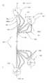
- the power plant 10includes a concentrated solar tower assembly 12 having a tower structure 14, where the solar receiver 100 is placed at the top. On the solar receiver 100, solar rays are concentrated from solar field comprised of heliostats 16 for collecting thermal energy in a heat transfer fluid.
- the power plant 10may further include hot and cold storage tanks 18, 20, respectively, and a Rankine cycle power block 22 to generate electricity.
- the molten salt fluid at the solar receiver 100is being heated through focusing the sunlight via heliostats 16.
- the hot saltis stored in the hot storage tank 18, at temperature of about 565°C, and after thermal energy thereof is being utilized by the cycle 22 for producing electricity through generator 'G', it is stored in the cold storage tank 20, at temperature of about 290°C, from where it is further sent to the solar receiver 100 to be reheated.
- FIG. 1is depiction of molten salt solar power plant configuration, however without departing from the scope of the present disclosure, the invention described in this disclosure is open to other solar power plant configuration.
- FIGS. 2 to 4Bvarious diagrams depicting the portions of the receiver panels with improved panel arrangement design that may be successfully utilized in relation to any solar operated power plants in an effective and economical way in the solar receiver using water, steam, molten salt and other heat transfer fluids.
- the solar receivermay include a variety of components for performing their assigned purpose, and only those components are shown that are relevant for the description of various embodiments of the present disclosure.
- FIG. 2is an example solid depiction of a portion of the solar receiver 100.
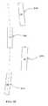
- FIG. 3Ais a side elevation view of a panel arrangement of the solar receiver 100.
- FIG. 3Bis a top plane view of a panel arrangement of the solar receiver 100.
- the solar receiver 100includes a plurality of receiver heat transfer passes 120 (hereinafter referred to as 'HT pass 120').
- the HT passes 120which define flow directions of the fluid may be arranged to configure the solar receiver 100 of varying size and shapes, such as, circular, oval, square, etc.
- Each HT pass 120includes a plurality of panels 130.
- each panel 130includes a plurality of tubes 140, tangentially arranged, vertically extending between horizontally placed lower 142 and upper headers 144 to form a substantially continuous tube surface 146.
- Such continuous tube surface 146enables solar heating of the fluid flow therefrom in a parallel flow arrangement or a serpentine flow arrangement or in any other combination.
- the upper headers 144may include various header nipples 148 configured perpendicular to respective headers 144 surfaces. Each header nipple 148 is coupled to a respective tube 140 to enable fluid source connection to supply fluid to the plurality of tubes 140 via the respective headers 144 for the solar heating.
- headers 142 and 144may include nozzle connection ports 150 to enable connection between the respective headers and manifolds to supply and exit of the fluid from the panels 130, as known in the art.
- the plurality of tubes 140comprises a predetermined number of bent tube assemblies.
- the tubes 140are adapted to be bent two-dimensionally at proximate to each of the lower 142 and upper 144 headers enabling equal fluid flow distribution to each tube 140 within the panel 130.
- the two dimensional bend of the tubes 140are like that includes maximum of two bends, such as B1 and B2, (as shown in FIG. 3A ) in the tube 140 at proximate to each of the lower 142 and upper 144 headers.
- some tubesmay be straight, without any bend.
- predetermined numbers of straight and bent tubes 140may in any suitable manner as found appropriate be arranged between the headers 142, 144 while configuring the panel 130.
- the two-dimensional tube bendsenable convenient manufacturing and production quality control, and enabling simplified spare part inventory and unit repair for the production of the solar receiver 100.
- at least one tube, such as a tube 140 1 (as shown in FIG. 3A ) of the plurality of tubes 140 in each panel 130is assigned to be coupled at a bottom-most portion 144 bm of the respective upper headers 144.
- Such tube 140 1allows self-draining of the fluids from each of the plurality of panels 130 making the panels fully drainable.
- the headers 142, 144 of adjacent panels 130are horizontally ( ⁇ H) and vertically ( ⁇ V) offset one to another at distal ends of the substantially continuous tube surface 146.
- Each panel 130includes the vertically offset ( ⁇ V) header 142, 144, which is adjacent to a panel having the horizontally offset ( ⁇ H) header 142, 144 forming horizontally and vertically offset ( ⁇ H, ⁇ V) adjacent headers 142, 144, one to another, on each side: upper 'U' and lower 'L' of the solar receiver 100.
- the panel, such as 130, having the upper header 144 vertically offset ( ⁇ V)is adapted to include the lower header 142 horizontally offset ( ⁇ H), to balance the characteristic pressure drop of the adjacent panels 130 having a similar combination of vertically and horizontally offset headers.
- one panelsuch as the panel 130
- another panelsuch as the panel 130
- the upper header 1Uis horizontally ( ⁇ H) and vertically ( ⁇ V) offset with respect to the adjacent upper header 2U and vice versa.
- the upper header 2Uis considered to be horizontally offset ( ⁇ H) and vertically offset ( ⁇ V) with respect to the upper header 3U. Similar arrangement is with the lower side 'L' of the solar receiver 100.
- FIG. 3Billustrates the top plane view of such alternate horizontally ( ⁇ H) and vertically ( ⁇ V) offset headers arrangement of the solar receiver 100, which is shown to include various headers 1U, 2U, 3U...NU (where 'N' is the last in a series of panels) for understanding purpose.
- the headers 142, 144are configured of cylindrical pipe assemblies with closed ends, as depicted for example with respect to the header 144 with closed ends 144a, 144b, in FIG. 2 .
- various other configurations of the headers and ends thereofmay be possible and may be incorporated from time to time and shall be considered to be included within the scope of the present disclosure.
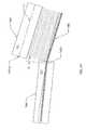
- adjacent headers (upper and lower) 142, 144are adapted to be disposed at minimum vertical distance ( ⁇ V) between top T CV and bottom B CV curvatures (as seen in FIG. 3A ) thereof.
- ⁇ Vminimum vertical distance between top T CV and bottom B CV curvatures
- the adjacent headers 142, 144 apart from being disposed at minimum vertical distance ( ⁇ V) between top T CV and bottom B CV curvaturesare also adapted to be disposed at a minimum horizontal ( ⁇ H) distance between centerlines LC of the adjacent headers 142, 144, allowing an edge tube 140 ET of one of the panel to have a suitable clearance 'S' with an outermost edge 144 OE of the header (1U) of the adjacent panel.
- ⁇ Vminimum vertical distance
- ⁇ Hminimum horizontal
- the parameterssuch as the overall length of each header (HL), the angle of orientation ( ⁇ ) and appropriate horizontal offset ( ⁇ H) are responsible.
- HLoverall length of each header
- ⁇angle of orientation
- ⁇ Happropriate horizontal offset
- Such solar receiver with improved panel arrangement designmay be capable of minimizing the gap between edge tubes of adjacent panels while balancing other constraints, such as, minimum receiver diameter, ease of manufacturing and erection, full drainability and reduced bending stress.
- simple two dimensional tube bends for the connection between the header and heat transfer surfaceminimizes manufacturing costs associated with other complicated tube bends, such as three dimensional bends.
- Placement of at least one tube at the bottom of the headerguarantees substantially complete drainage of fluids, minimizing the possibility of blockage due to heat transfer fluid freeze, in one example.
- substantially smaller header length in the solar receiverreduces material and handling cost as the header nipples can be placed very close to the header end caps.
Landscapes
- Engineering & Computer Science (AREA)
- Physics & Mathematics (AREA)
- Life Sciences & Earth Sciences (AREA)
- Sustainable Development (AREA)
- Sustainable Energy (AREA)
- Thermal Sciences (AREA)
- Chemical & Material Sciences (AREA)
- Combustion & Propulsion (AREA)
- Mechanical Engineering (AREA)
- General Engineering & Computer Science (AREA)
- Photovoltaic Devices (AREA)
- Heat-Exchange Devices With Radiators And Conduit Assemblies (AREA)
Abstract
Description
- The present invention relates to a solar central receiver of a concentrated power tower plant, and, more particularly, to an improved panel and header arrangement and orientation of panels comprising a heat transfer surface for a solar central receiver.
- In a typical arrangement of a concentrated solar power plant, a large field of heliostats is arranged around a solar central receiver (solar receiver) placed on a tower of substantial height, where the heliostats focus direct sunlight on to the solar receiver to provide heat to a heat transfer fluid, which is applied to produce steam to run a turbine and extract work in order to produce electricity. The solar receiver generally includes various vertical panels, each having fluid-carrying vertical tubes arranged between horizontally disposed headers for distribution of fluid into the tubes. Tube panel arrangements for configuring the solar receiver are important to effectively utilize solar flux without any spillage or leakage (solar energy not received on the heat transfer surface so as to be absorbed into the heat transfer medium) and proper functioning of the solar receiver.
- In one arrangement each panel of the heat transfer surface comprises a flat vertical tube panel between inlet and outlet headers, wherein the headers are positioned in a plane common to the centerline of the tube panel surface. In such an arrangement the adjacent panels of the solar receiver are positioned with spacing therebetween the edge tubes of adjacent panels to accommodate the length of the panel headers. The size of the spacing between panels' edge tubes is such that the thermal expansion of the panels is insufficient to close the spacing between panels' edge tubes, resulting in spillage or leakage of solar flux, possibly causing damage of solar receiver's internal components.
- Such problem may be seen to be addressed in United State Patent No.
US6931851B1 (US'851), where the constant spacing between the adjacent panels has been addressed by providing a solar receiver with inboard headers with alternative designs of staggered and beveled. However, to one knowledgeable in the art it will be obvious that in the process of creating such inboard header arrangements other issues, such as, manufacturing limitations, fluid drainage restrictions, complications in erection of the receiver, maintainability of the receiver, are added to the design. - Accordingly, there exists a need for an improved solar receiver, which may be capable of maintaining a constant spacing of the panel arrangements while balancing other constrains and issues as discussed above and provides additional features and advantages.
- The present disclosure describes a solar receiver with an improved header and panel design that will be presented in the following simplified summary to provide a basic understanding of one or more aspects of the disclosure that are intended to overcome the discussed drawbacks, but to include all advantages thereof, along with providing some additional advantages. This summary is not an extensive overview of the disclosure. It is intended to neither identify key or critical elements of the disclosure, nor to delineate the scope of the present disclosure. Rather, the sole purpose of this summary is to present some concepts of the disclosure, its aspects and advantages in a simplified form as a prelude to the more detailed description that is presented hereinafter.
- An object of the present disclosure is to describe a solar receiver with improved panel and header design, which may be capable of maintaining a constant spacing of the panel arrangements while balancing other constraints, such as, minimum receiver diameter, ease of manufacturing and erection, full drainability and reduced bending stress. Further, an object of the present disclosure is to describe a solar receiver with improved panel and header design, which may be convenient to use in an effective and economical way in solar receivers that use water, steam, molten salt and other heat transfer fluids. Various other objects and features of the present disclosure will be apparent from the following detailed description and claims.
- The above noted and other objects, in one aspect, may be achieved by a solar receiver configuration (receiver) adapted to include a plurality of receiver heat transfer passes (pass) arranged to form a substantially continuous heat transfer surface. Each pass includes a plurality of panels. Further, each panel includes a plurality of tubes, tangentially arranged, vertically extending between horizontally placed lower and upper headers. The headers, which are pipe assemblies with closed ends, of adjacent panels are horizontally and vertically offset one to another to form a substantially continuous tube surface. Such continuous tube surface enables solar heating of the fluid flow therefrom in at least a parallel flow arrangement and a serpentine flow arrangement. Such arrangement of the receiver enables constant spacing of the panel arrangements in the minimum receiver diameter.
- In one arrangement of the receiver, adjacent headers are adapted to be disposed at minimum vertical distance between top and bottom curvatures thereof. Further, the adjacent headers are adapted to be disposed at a minimum horizontal distance between centerlines of the adjacent headers, allowing an edge tube of one of the panel to clear an outermost edge of the header of the adjacent panel. Such adjacent header arrangement enables convenient assembly and dis-assembly of the plurality of panels.
- In one arrangement of the receiver, each panel having a vertically offset header is adjacent to, on each side, a panel having a horizontally offset header forming horizontally and vertically offset adjacent headers, one to another. The panels having the upper header vertically offset is adapted to include a lower header horizontally offset, to balance the characteristic pressure drop of the adjacent panels having a similar combination of vertically and horizontally offset headers for each panel assembly.
- In one arrangement of the receiver, at least one tube of the plurality of tubes in each panel is assigned to be coupled at a bottom-most portion of the respective upper header. Such a tube allows self-draining of the fluids from each of the plurality of panels making the panels fully drainable.
- In one arrangement of the receiver, the plurality of tubes comprises a predetermined numbers of bent tube assemblies adapted to be bent two-dimensionally at proximate to each of the lower and upper headers enabling equal fluid distribution to each tube within the panel enabling convenient manufacturing and production quality control, and enabling simplified spare part inventory and unit repair.
- These together with the other aspects of the present disclosure, along with the various features of novelty that characterize the present disclosure, are pointed out with particularity in the present disclosure. For a better understanding of the present disclosure, its operating advantages, and its uses, reference should be made to the accompanying drawings and descriptive matter in which there are illustrated exemplary embodiments of the present disclosure.
- The advantages and features of the present disclosure will be better understood with reference to the following detailed description and claims taken in conjunction with the accompanying drawing, wherein like elements are identified with like symbols, and in which:
FIG. 1 illustrates an example of a concentrated solar power plant, in accordance with an exemplary embodiment of the present disclosure;FIG. 2 illustrates an example solid depiction of a portion of a solar receiver, in accordance with second exemplary embodiment of the present disclosure;FIGS. 3A and3B illustrate example diagrams of receiver panels and an improved header design pattern, in accordance with third exemplary embodiment of the present disclosure; andFIGS. 4A and4B illustrate example line diagrams of receiver panels and an improved header design clearance with respect to adjacent headers, in accordance with third exemplary embodiment of the present disclosure.- Like reference numerals refer to like parts throughout the description of several views of the drawings.
- For a thorough understanding of the present disclosure, reference is to be made to the following detailed description, including the appended claims, in connection with the above described drawings. In the following description, for purposes of explanation, numerous specific details are set forth in order to provide a thorough understanding of the present disclosure. It will be apparent, however, to one skilled in the art that the present disclosure can be practiced without these specific details. In other instances, structures and apparatuses are shown in block diagrams form only, in order to avoid obscuring the disclosure. Reference in this specification to "one embodiment," "an embodiment," "another embodiment," "various embodiments," means that a particular feature, structure, or characteristic described in connection with the embodiment is included in at least one embodiment of the present disclosure. The appearance of the phrase "in one embodiment" in various places in the specification are not necessarily all referring to the same embodiment, nor are separate or alternative embodiments mutually exclusive of other embodiments. Moreover, various features are described which may be exhibited by some embodiments and not by others. Similarly, various requirements are described which may be requirements for some embodiments but may not be of other embodiment's requirement.
- Although the following description contains many specifics for the purposes of illustration, anyone skilled in the art will appreciate that many variations and/or alterations to these details are within the scope of the present disclosure. Similarly, although many of the features of the present disclosure are described in terms of each other, or in conjunction with each other, one skilled in the art will appreciate that many of these features can be provided independently of other features. Accordingly, this description of the present disclosure is set forth without any loss of generality to, and without imposing limitations upon, the present disclosure. The terms "a" and "an" herein do not denote a limitation of quantity, but rather denote the presence of at least one of the referenced item.
- Referring now to
FIG. 1 , an example of a concentratedsolar power plant 10 with asolar receiver 100 is illustrated, in accordance with an exemplary embodiment of the present disclosure. Thepower plant 10 includes a concentratedsolar tower assembly 12 having atower structure 14, where thesolar receiver 100 is placed at the top. On thesolar receiver 100, solar rays are concentrated from solar field comprised ofheliostats 16 for collecting thermal energy in a heat transfer fluid. Thepower plant 10 may further include hot andcold storage tanks cycle power block 22 to generate electricity. The molten salt fluid at thesolar receiver 100 is being heated through focusing the sunlight viaheliostats 16. The hot salt is stored in thehot storage tank 18, at temperature of about 565°C, and after thermal energy thereof is being utilized by thecycle 22 for producing electricity through generator 'G', it is stored in thecold storage tank 20, at temperature of about 290°C, from where it is further sent to thesolar receiver 100 to be reheated. AlthoughFIG. 1 is depiction of molten salt solar power plant configuration, however without departing from the scope of the present disclosure, the invention described in this disclosure is open to other solar power plant configuration. - In as much as the construction and arrangement of the
power plant 10 with thesolar receiver 100 along with said other components are all well-known to those skilled in the art, it is not deemed necessary for purposes of acquiring an understanding of the present disclosure that there be recited herein all of the constructional details and explanation thereof. Rather, it is deemed sufficient to simply note that as shown inFIGS. 2 to 4B , various diagrams depicting the portions of the receiver panels with improved panel arrangement design that may be successfully utilized in relation to any solar operated power plants in an effective and economical way in the solar receiver using water, steam, molten salt and other heat transfer fluids. Further, it should be understood that the solar receiver may include a variety of components for performing their assigned purpose, and only those components are shown that are relevant for the description of various embodiments of the present disclosure. - As shown in
FIGS. 2 ,3A and3B and described in conjunction with each other, is thesolar receiver 100 and its essential components. Specifically,FIG. 2 is an example solid depiction of a portion of thesolar receiver 100.FIG. 3A is a side elevation view of a panel arrangement of thesolar receiver 100.FIG. 3B is a top plane view of a panel arrangement of thesolar receiver 100. Thesolar receiver 100 includes a plurality of receiver heat transfer passes 120 (hereinafter referred to as 'HT pass 120'). The HT passes 120, which define flow directions of the fluid may be arranged to configure thesolar receiver 100 of varying size and shapes, such as, circular, oval, square, etc. Each HT pass 120 includes a plurality ofpanels 130. Further, eachpanel 130 includes a plurality oftubes 140, tangentially arranged, vertically extending between horizontally placed lower 142 andupper headers 144 to form a substantiallycontinuous tube surface 146. Suchcontinuous tube surface 146 enables solar heating of the fluid flow therefrom in a parallel flow arrangement or a serpentine flow arrangement or in any other combination. In one embodiment, theupper headers 144 may includevarious header nipples 148 configured perpendicular torespective headers 144 surfaces. Eachheader nipple 148 is coupled to arespective tube 140 to enable fluid source connection to supply fluid to the plurality oftubes 140 via therespective headers 144 for the solar heating. In one of the additional embodiment,headers nozzle connection ports 150 to enable connection between the respective headers and manifolds to supply and exit of the fluid from thepanels 130, as known in the art. - In one arrangement of the
solar receiver 100, the plurality oftubes 140 comprises a predetermined number of bent tube assemblies. Without limiting the bent tube designs, in one exemplary embodiment, thetubes 140 are adapted to be bent two-dimensionally at proximate to each of the lower 142 and upper 144 headers enabling equal fluid flow distribution to eachtube 140 within thepanel 130. Specifically, the two dimensional bend of thetubes 140 are like that includes maximum of two bends, such as B1 and B2, (as shown inFIG. 3A ) in thetube 140 at proximate to each of the lower 142 and upper 144 headers. Further, apart from some bent tubes, some tubes may be straight, without any bend. For configuring thepanel 130, predetermined numbers of straight andbent tubes 140 may in any suitable manner as found appropriate be arranged between theheaders panel 130. The two-dimensional tube bends enable convenient manufacturing and production quality control, and enabling simplified spare part inventory and unit repair for the production of thesolar receiver 100. Further at least one tube, such as a tube 1401 (as shown inFIG. 3A ) of the plurality oftubes 140 in eachpanel 130 is assigned to be coupled at abottom-most portion 144bm of the respectiveupper headers 144.Such tube 1401 allows self-draining of the fluids from each of the plurality ofpanels 130 making the panels fully drainable. - Further, the
headers tubes 140 of eachpanel 130 are adapted to be arranged in a particular manner with respect to each other. Specifically, theheaders adjacent panels 130 are horizontally (ΔH) and vertically (ΔV) offset one to another at distal ends of the substantiallycontinuous tube surface 146. Eachpanel 130 includes the vertically offset (ΔV)header header adjacent headers solar receiver 100. The panel, such as 130, having theupper header 144 vertically offset (ΔV) is adapted to include thelower header 142 horizontally offset (ΔH), to balance the characteristic pressure drop of theadjacent panels 130 having a similar combination of vertically and horizontally offset headers. - This can be understood more clearly by reference to
FIG. 3A and3B , where one panel, such as thepanel 130, includes upper 1U and lower 1L headers indicating the upper 'U' and lower 'L' of thesolar receiver 100. Similarly, another panel, such as thepanel 130, includes upper 2U and lower 2L headers indicating the upper 'U' and lower 'L' of thesolar receiver 100. The upper header 1U is horizontally (ΔH) and vertically (ΔV) offset with respect to the adjacentupper header 2U and vice versa. Further, theupper header 2U is considered to be horizontally offset (ΔH) and vertically offset (ΔV) with respect to theupper header 3U. Similar arrangement is with the lower side 'L' of thesolar receiver 100. Such an arrangement of theheaders solar receiver 100.FIG. 3B illustrates the top plane view of such alternate horizontally (ΔH) and vertically (ΔV) offset headers arrangement of thesolar receiver 100, which is shown to includevarious headers - In one embodiment of the present disclosure, the
headers header 144 withclosed ends FIG. 2 . However, without departing from the scope of the present disclosure various other configurations of the headers and ends thereof may be possible and may be incorporated from time to time and shall be considered to be included within the scope of the present disclosure. - Further, in one essential embodiment, adjacent headers (upper and lower) 142, 144 are adapted to be disposed at minimum vertical distance (ΔV) between top TCV and bottom BCV curvatures (as seen in
FIG. 3A ) thereof. However, without departing from the scope of the present disclosure, such vertical distance (ΔV) may be specified as per the requirement of the system to perform in an efficient and economical manner. - Referring now to
FIGS. 4A and4B , described in conjunction withFIGS. 3A and3B , theadjacent headers adjacent headers edge tube 140ET of one of the panel to have a suitable clearance 'S' with anoutermost edge 144OE of the header (1U) of the adjacent panel. To obtain such clearance 'S' between theedge tube 140ET of one of the panels and theoutermost edge 144OE of the header (1U) of the adjacent panel, as shown inFIG. 4B , the parameters such as the overall length of each header (HL), the angle of orientation (Φ) and appropriate horizontal offset (ΔH) are responsible. With such clearance 'S' between thepanel edge tube 140ET of one of the panels and theoutermost edge 144OE of the header (1U) of the adjacent panel convenient assembly and dis-assembly of the plurality of panels may be achieved. - The invention of the present disclosure is advantageous in various scopes. Such solar receiver with improved panel arrangement design may be capable of minimizing the gap between edge tubes of adjacent panels while balancing other constraints, such as, minimum receiver diameter, ease of manufacturing and erection, full drainability and reduced bending stress. Specifically, simple two dimensional tube bends for the connection between the header and heat transfer surface minimizes manufacturing costs associated with other complicated tube bends, such as three dimensional bends. Placement of at least one tube at the bottom of the header guarantees substantially complete drainage of fluids, minimizing the possibility of blockage due to heat transfer fluid freeze, in one example. Further, substantially smaller header length in the solar receiver reduces material and handling cost as the header nipples can be placed very close to the header end caps. Further, supportive headers arrangement minimizes sustained stress on the header nipples. Furthermore, clearance between the edge tube of one of the panel and the outermost edge of the header of the adjacent panel enables convenient assembly and dis-assembly of the plurality of panels. Moreover, the solar receiver with improved header and panel design may be convenient to use in an effective and economical way in solar receiver using water, steam, molten salt and other heat transfer fluids. Various other advantages and features of the present disclosure are apparent from the above detailed description and appendage claims.
- The foregoing descriptions of specific embodiments of the present disclosure have been presented for purposes of illustration and description. They are not intended to be exhaustive or to limit the present disclosure to the precise forms disclosed, and obviously many modifications and variations are possible in light of the above teaching. The embodiments were chosen and described in order to best explain the principles of the present disclosure and its practical application, to thereby enable others skilled in the art to best utilize the present disclosure and various embodiments with various modifications as are suited to the particular use contemplated. It is understood that various omission and substitutions of equivalents are contemplated as circumstance may suggest or render expedient, but such are intended to cover the application or implementation without departing from the spirit or scope of the claims of the present disclosure.
- 10
- Concentrated solar power plant, power plant
- 12
- Concentrated solar tower assembly
- 14
- Tower structure
- 16
- Heliostats
- 18
- Hot storage tank
- 20
- Cold storage tank
- 22
- Rankine cycle power block
- 100
- Solar receiver
- 120
- Receiver heat transfer passes, HT Pass
- 130
- Panels
- 140, 1401
- Tubes
- 140ET
- Edge tube
- 142
- Lower headers
- 144
- Upper headers
- 144a, 144b
- Closed header ends
- 144bm
- Bottom-most portion of header
- 144OE
- Outermost edge of the header
- 146
- Tube surface
- 148
- Header nipples
- 150
- Nozzle connection ports
- B1, B2
- Tube bends
- U, L
- Upper and lower of the solar receiver
- ΔV, ΔH
- Vertical and horizontal offsets
- 1U, 2U
- Upper headers
- 1L, 2L
- Lower headers
- TCV, BCV
- Top and bottom curvatures of headers
- LC
- Centerlines of a header
- S
- Clearance
- HL
- Header Length
- Φ
- Angle of orientation
- G
- Generator
Claims (7)
- A solar receiver configuration, comprising:a plurality of receiver heat transfer passes, each pass having a plurality of panels enabling fluid flow therefrom; andeach panel having a plurality of tubes, tangentially arranged, vertically extending between horizontally placed lower and upper headers, wherein the headers, pipe assemblies with closed ends, of adjacent panels are horizontally and vertically offset one to another to form a substantially continuous tube surface to enable solar heating of fluid flow therefrom in at least a parallel flow arrangement and a serpentine flow arrangement.
- The solar receiver configuration as claimed in claim 1, wherein adjacent headers are adapted to be disposed at minimum vertical distance between top and bottom curvatures thereof to enable convenient assembly and dis-assembly of the plurality of panels.
- The solar receiver configuration as claimed in claim 1, wherein the adjacent headers are adapted to be disposed at a minimum horizontal distance between respective centerlines of the adjacent headers, allowing an edge tube of one of the panel to clear an outermost, near-side edge of the header of the adjacent panel to enable convenient assembly and dis-assembly of the plurality of panels.
- The solar receiver configuration as claimed in claim 1, wherein each panel having a vertically offset header is adjacent to, on each side, a panel having a horizontally offset header to form horizontally and vertically offset adjacent headers, one to another.
- The solar receiver configuration as claimed in claim 4, wherein at least one of the panel having the upper header vertically offset is adapted to comprise the lower header horizontally offset, to balance the characteristic pressure drop of the adjacent panels having a similar combination of vertically and horizontally offset headers for each panel assembly.
- The solar receiver configuration as claimed in claim 1, wherein at least one tube of the plurality of tubes in each panel is assigned to be coupled at a bottom-most portion of the respective upper header to allow self-draining of the fluids from each of the plurality of panels.
- The solar receiver configuration as claimed in claim 1, wherein the plurality of tubes comprises a predetermined number of bent tube assemblies adapted to be bent two-dimensionally at proximate to each of the lower and upper headers enabling equal fluid distribution to each tube within the panel.
Applications Claiming Priority (1)
| Application Number | Priority Date | Filing Date | Title |
|---|---|---|---|
| US14/302,953US9719696B2 (en) | 2014-06-12 | 2014-06-12 | Solar receiver configuration |
Publications (2)
| Publication Number | Publication Date |
|---|---|
| EP2955461A1true EP2955461A1 (en) | 2015-12-16 |
| EP2955461B1 EP2955461B1 (en) | 2019-05-08 |
Family
ID=53298284
Family Applications (1)
| Application Number | Title | Priority Date | Filing Date |
|---|---|---|---|
| EP15171232.0ANot-in-forceEP2955461B1 (en) | 2014-06-12 | 2015-06-09 | Improved solar receiver configuration |
Country Status (7)
| Country | Link |
|---|---|
| US (1) | US9719696B2 (en) |
| EP (1) | EP2955461B1 (en) |
| CN (1) | CN105318569B (en) |
| DK (1) | DK2955461T3 (en) |
| ES (1) | ES2734220T3 (en) |
| MA (1) | MA38160B1 (en) |
| ZA (1) | ZA201504136B (en) |
Cited By (2)
| Publication number | Priority date | Publication date | Assignee | Title |
|---|---|---|---|---|
| CN111895667A (en)* | 2020-09-02 | 2020-11-06 | 衢州市特种设备检验中心 | A new type of molten salt heat sink |
| EP3710761A4 (en)* | 2017-11-15 | 2021-12-08 | Vast Solar Pty Ltd | RECEIVER OF CONCENTRATED SOLAR ENERGY |
Families Citing this family (1)
| Publication number | Priority date | Publication date | Assignee | Title |
|---|---|---|---|---|
| CN116202235A (en)* | 2023-03-07 | 2023-06-02 | 河北工业大学 | Solar heat absorber with circumferential array type radial bending coiled pipe |
Citations (6)
| Publication number | Priority date | Publication date | Assignee | Title |
|---|---|---|---|---|
| FR2438804A1 (en)* | 1978-10-10 | 1980-05-09 | Babcock & Wilcox Co | SOLAR BOILER |
| EP0106687A2 (en)* | 1982-10-14 | 1984-04-25 | The Babcock & Wilcox Company | Tube panels and solar receivers incorporating such panels |
| US4485803A (en)* | 1982-10-14 | 1984-12-04 | The Babcock & Wilcox Company | Solar receiver with interspersed panels |
| US5862800A (en)* | 1996-09-27 | 1999-01-26 | Boeing North American, Inc. | Molten nitrate salt solar central receiver of low cycle fatigue 625 alloy |
| US20040112374A1 (en)* | 2002-12-13 | 2004-06-17 | Litwin Robert Z. | Solar central receiver with inboard headers |
| EP2706307A1 (en)* | 2012-09-10 | 2014-03-12 | Wieghardt, Kai | Thermal solar tower power plant |
Family Cites Families (3)
| Publication number | Priority date | Publication date | Assignee | Title |
|---|---|---|---|---|
| US6736134B2 (en)* | 2001-09-05 | 2004-05-18 | The Boeing Company | Thin wall header for use in molten salt solar absorption panels |
| MX350102B (en)* | 2011-07-29 | 2017-08-25 | The Babcock & Wilcox Company * | Shop assembled vertical serpentine flow molten salt solar receiver. |
| CN202993600U (en)* | 2012-12-05 | 2013-06-12 | 昆明理工大学 | Heat collecting device heating fluid through combined use of smoke waste heat and solar energy |
- 2014
- 2014-06-12USUS14/302,953patent/US9719696B2/ennot_activeExpired - Fee Related
- 2015
- 2015-06-05MAMA38160Apatent/MA38160B1/enunknown
- 2015-06-08ZAZA2015/04136Apatent/ZA201504136B/enunknown
- 2015-06-09EPEP15171232.0Apatent/EP2955461B1/ennot_activeNot-in-force
- 2015-06-09DKDK15171232.0Tpatent/DK2955461T3/enactive
- 2015-06-09ESES15171232Tpatent/ES2734220T3/enactiveActive
- 2015-06-12CNCN201510321640.7Apatent/CN105318569B/ennot_activeExpired - Fee Related
Patent Citations (7)
| Publication number | Priority date | Publication date | Assignee | Title |
|---|---|---|---|---|
| FR2438804A1 (en)* | 1978-10-10 | 1980-05-09 | Babcock & Wilcox Co | SOLAR BOILER |
| EP0106687A2 (en)* | 1982-10-14 | 1984-04-25 | The Babcock & Wilcox Company | Tube panels and solar receivers incorporating such panels |
| US4485803A (en)* | 1982-10-14 | 1984-12-04 | The Babcock & Wilcox Company | Solar receiver with interspersed panels |
| US5862800A (en)* | 1996-09-27 | 1999-01-26 | Boeing North American, Inc. | Molten nitrate salt solar central receiver of low cycle fatigue 625 alloy |
| US20040112374A1 (en)* | 2002-12-13 | 2004-06-17 | Litwin Robert Z. | Solar central receiver with inboard headers |
| US6931851B2 (en) | 2002-12-13 | 2005-08-23 | The Boeing Company | Solar central receiver with inboard headers |
| EP2706307A1 (en)* | 2012-09-10 | 2014-03-12 | Wieghardt, Kai | Thermal solar tower power plant |
Cited By (2)
| Publication number | Priority date | Publication date | Assignee | Title |
|---|---|---|---|---|
| EP3710761A4 (en)* | 2017-11-15 | 2021-12-08 | Vast Solar Pty Ltd | RECEIVER OF CONCENTRATED SOLAR ENERGY |
| CN111895667A (en)* | 2020-09-02 | 2020-11-06 | 衢州市特种设备检验中心 | A new type of molten salt heat sink |
Also Published As
| Publication number | Publication date |
|---|---|
| CN105318569B (en) | 2019-01-08 |
| DK2955461T3 (en) | 2019-08-12 |
| CN105318569A (en) | 2016-02-10 |
| MA38160B1 (en) | 2017-04-28 |
| MA38160A1 (en) | 2016-09-30 |
| US20150362218A1 (en) | 2015-12-17 |
| ZA201504136B (en) | 2016-04-28 |
| US9719696B2 (en) | 2017-08-01 |
| EP2955461B1 (en) | 2019-05-08 |
| ES2734220T3 (en) | 2019-12-04 |
Similar Documents
| Publication | Publication Date | Title |
|---|---|---|
| JP5951396B2 (en) | Heat collector for solar boiler and tower solar boiler equipped with the same | |
| ES2425996B1 (en) | Solar plate receiver | |
| EP2955461B1 (en) | Improved solar receiver configuration | |
| EP2781741B1 (en) | System and method for pre-startup and post-shutdown preparations of steam generators or power plants | |
| US20200141568A1 (en) | Heat exchanger for molten salt steam generator in concentrated solar power plant | |
| CN105202948B (en) | A kind of adverse current type helical baffles U-tube bundle heat exchanger | |
| MX2014005493A (en) | High efficiency solar receiver. | |
| MX2020006067A (en) | Heat exchanger for a molten salt steam generator in a concentrated solar power plant (iii). | |
| EP2730856B1 (en) | Boiler for solar receiver | |
| CN106461268B (en) | External solar receiver and tower optically focused heating power solar power station | |
| EP3502608B1 (en) | Heat exchanger for a molten salt steam generator in a concentrated solar power plant (iii) | |
| AU2012200216B2 (en) | Heat transfer passes for solar boilers | |
| WO2016193095A1 (en) | A header device for a heat exchanger system, a heat exchanger system, and a method of heating a fluid | |
| US11739931B2 (en) | Heat exchanger, such as for a solar power plant | |
| RU2476802C2 (en) | Heating radiator from heat pipe | |
| EP1995542A2 (en) | Heat exchange device | |
| CN203908110U (en) | Micro-channel heat exchanger for heat pump water heater | |
| EP2730857B1 (en) | Solar receiver panel and support structure | |
| CN105222617A (en) | A kind of low flow resistance heat exchanger for natural cycle system | |
| CN204373488U (en) | A kind of floating head type Tube Bundle in Baffle Heat Exchanger | |
| CN202361825U (en) | New Asphalt Evaporation Cooler | |
| CN204478880U (en) | A kind of heat exchanger tube | |
| ES2735303B2 (en) | OUTDOOR TOWER SOLAR RECEIVER | |
| CN202451380U (en) | Central tower type power station and boiler thereof | |
| EP2767792A3 (en) | Heat exchanger and process of realizing thereof |
Legal Events
| Date | Code | Title | Description |
|---|---|---|---|
| PUAI | Public reference made under article 153(3) epc to a published international application that has entered the european phase | Free format text:ORIGINAL CODE: 0009012 | |
| AK | Designated contracting states | Kind code of ref document:A1 Designated state(s):AL AT BE BG CH CY CZ DE DK EE ES FI FR GB GR HR HU IE IS IT LI LT LU LV MC MK MT NL NO PL PT RO RS SE SI SK SM TR | |
| AX | Request for extension of the european patent | Extension state:BA ME | |
| 17P | Request for examination filed | Effective date:20160616 | |
| RBV | Designated contracting states (corrected) | Designated state(s):AL AT BE BG CH CY CZ DE DK EE ES FI FR GB GR HR HU IE IS IT LI LT LU LV MC MK MT NL NO PL PT RO RS SE SI SK SM TR | |
| RAP1 | Party data changed (applicant data changed or rights of an application transferred) | Owner name:GENERAL ELECTRIC TECHNOLOGY GMBH | |
| STAA | Information on the status of an ep patent application or granted ep patent | Free format text:STATUS: EXAMINATION IS IN PROGRESS | |
| 17Q | First examination report despatched | Effective date:20180629 | |
| REG | Reference to a national code | Ref country code:DE Ref legal event code:R079 Ref document number:602015029672 Country of ref document:DE Free format text:PREVIOUS MAIN CLASS: F24J0002070000 Ipc:F24S0080300000 | |
| RIC1 | Information provided on ipc code assigned before grant | Ipc:F24S 20/20 20180101ALI20181205BHEP Ipc:F24S 80/30 20180101AFI20181205BHEP Ipc:F24S 10/70 20180101ALI20181205BHEP | |
| GRAP | Despatch of communication of intention to grant a patent | Free format text:ORIGINAL CODE: EPIDOSNIGR1 | |
| STAA | Information on the status of an ep patent application or granted ep patent | Free format text:STATUS: GRANT OF PATENT IS INTENDED | |
| INTG | Intention to grant announced | Effective date:20190114 | |
| GRAS | Grant fee paid | Free format text:ORIGINAL CODE: EPIDOSNIGR3 | |
| GRAA | (expected) grant | Free format text:ORIGINAL CODE: 0009210 | |
| STAA | Information on the status of an ep patent application or granted ep patent | Free format text:STATUS: THE PATENT HAS BEEN GRANTED | |
| AK | Designated contracting states | Kind code of ref document:B1 Designated state(s):AL AT BE BG CH CY CZ DE DK EE ES FI FR GB GR HR HU IE IS IT LI LT LU LV MC MK MT NL NO PL PT RO RS SE SI SK SM TR | |
| REG | Reference to a national code | Ref country code:GB Ref legal event code:FG4D | |
| REG | Reference to a national code | Ref country code:CH Ref legal event code:EP Ref country code:AT Ref legal event code:REF Ref document number:1130775 Country of ref document:AT Kind code of ref document:T Effective date:20190515 | |
| REG | Reference to a national code | Ref country code:DE Ref legal event code:R096 Ref document number:602015029672 Country of ref document:DE Ref country code:IE Ref legal event code:FG4D | |
| REG | Reference to a national code | Ref country code:DK Ref legal event code:T3 Effective date:20190807 | |
| REG | Reference to a national code | Ref country code:NL Ref legal event code:MP Effective date:20190508 | |
| REG | Reference to a national code | Ref country code:LT Ref legal event code:MG4D | |
| PG25 | Lapsed in a contracting state [announced via postgrant information from national office to epo] | Ref country code:LT Free format text:LAPSE BECAUSE OF FAILURE TO SUBMIT A TRANSLATION OF THE DESCRIPTION OR TO PAY THE FEE WITHIN THE PRESCRIBED TIME-LIMIT Effective date:20190508 Ref country code:NO Free format text:LAPSE BECAUSE OF FAILURE TO SUBMIT A TRANSLATION OF THE DESCRIPTION OR TO PAY THE FEE WITHIN THE PRESCRIBED TIME-LIMIT Effective date:20190808 Ref country code:FI Free format text:LAPSE BECAUSE OF FAILURE TO SUBMIT A TRANSLATION OF THE DESCRIPTION OR TO PAY THE FEE WITHIN THE PRESCRIBED TIME-LIMIT Effective date:20190508 Ref country code:NL Free format text:LAPSE BECAUSE OF FAILURE TO SUBMIT A TRANSLATION OF THE DESCRIPTION OR TO PAY THE FEE WITHIN THE PRESCRIBED TIME-LIMIT Effective date:20190508 Ref country code:PT Free format text:LAPSE BECAUSE OF FAILURE TO SUBMIT A TRANSLATION OF THE DESCRIPTION OR TO PAY THE FEE WITHIN THE PRESCRIBED TIME-LIMIT Effective date:20190908 Ref country code:AL Free format text:LAPSE BECAUSE OF FAILURE TO SUBMIT A TRANSLATION OF THE DESCRIPTION OR TO PAY THE FEE WITHIN THE PRESCRIBED TIME-LIMIT Effective date:20190508 Ref country code:SE Free format text:LAPSE BECAUSE OF FAILURE TO SUBMIT A TRANSLATION OF THE DESCRIPTION OR TO PAY THE FEE WITHIN THE PRESCRIBED TIME-LIMIT Effective date:20190508 Ref country code:HR Free format text:LAPSE BECAUSE OF FAILURE TO SUBMIT A TRANSLATION OF THE DESCRIPTION OR TO PAY THE FEE WITHIN THE PRESCRIBED TIME-LIMIT Effective date:20190508 | |
| PG25 | Lapsed in a contracting state [announced via postgrant information from national office to epo] | Ref country code:GR Free format text:LAPSE BECAUSE OF FAILURE TO SUBMIT A TRANSLATION OF THE DESCRIPTION OR TO PAY THE FEE WITHIN THE PRESCRIBED TIME-LIMIT Effective date:20190809 Ref country code:RS Free format text:LAPSE BECAUSE OF FAILURE TO SUBMIT A TRANSLATION OF THE DESCRIPTION OR TO PAY THE FEE WITHIN THE PRESCRIBED TIME-LIMIT Effective date:20190508 Ref country code:LV Free format text:LAPSE BECAUSE OF FAILURE TO SUBMIT A TRANSLATION OF THE DESCRIPTION OR TO PAY THE FEE WITHIN THE PRESCRIBED TIME-LIMIT Effective date:20190508 Ref country code:BG Free format text:LAPSE BECAUSE OF FAILURE TO SUBMIT A TRANSLATION OF THE DESCRIPTION OR TO PAY THE FEE WITHIN THE PRESCRIBED TIME-LIMIT Effective date:20190808 | |
| REG | Reference to a national code | Ref country code:ES Ref legal event code:FG2A Ref document number:2734220 Country of ref document:ES Kind code of ref document:T3 Effective date:20191204 | |
| REG | Reference to a national code | Ref country code:AT Ref legal event code:MK05 Ref document number:1130775 Country of ref document:AT Kind code of ref document:T Effective date:20190508 | |
| REG | Reference to a national code | Ref country code:DE Ref legal event code:R119 Ref document number:602015029672 Country of ref document:DE | |
| PG25 | Lapsed in a contracting state [announced via postgrant information from national office to epo] | Ref country code:EE Free format text:LAPSE BECAUSE OF FAILURE TO SUBMIT A TRANSLATION OF THE DESCRIPTION OR TO PAY THE FEE WITHIN THE PRESCRIBED TIME-LIMIT Effective date:20190508 Ref country code:CZ Free format text:LAPSE BECAUSE OF FAILURE TO SUBMIT A TRANSLATION OF THE DESCRIPTION OR TO PAY THE FEE WITHIN THE PRESCRIBED TIME-LIMIT Effective date:20190508 Ref country code:AT Free format text:LAPSE BECAUSE OF FAILURE TO SUBMIT A TRANSLATION OF THE DESCRIPTION OR TO PAY THE FEE WITHIN THE PRESCRIBED TIME-LIMIT Effective date:20190508 Ref country code:RO Free format text:LAPSE BECAUSE OF FAILURE TO SUBMIT A TRANSLATION OF THE DESCRIPTION OR TO PAY THE FEE WITHIN THE PRESCRIBED TIME-LIMIT Effective date:20190508 Ref country code:SK Free format text:LAPSE BECAUSE OF FAILURE TO SUBMIT A TRANSLATION OF THE DESCRIPTION OR TO PAY THE FEE WITHIN THE PRESCRIBED TIME-LIMIT Effective date:20190508 | |
| REG | Reference to a national code | Ref country code:CH Ref legal event code:PL | |
| PG25 | Lapsed in a contracting state [announced via postgrant information from national office to epo] | Ref country code:IT Free format text:LAPSE BECAUSE OF FAILURE TO SUBMIT A TRANSLATION OF THE DESCRIPTION OR TO PAY THE FEE WITHIN THE PRESCRIBED TIME-LIMIT Effective date:20190508 Ref country code:SM Free format text:LAPSE BECAUSE OF FAILURE TO SUBMIT A TRANSLATION OF THE DESCRIPTION OR TO PAY THE FEE WITHIN THE PRESCRIBED TIME-LIMIT Effective date:20190508 Ref country code:MC Free format text:LAPSE BECAUSE OF FAILURE TO SUBMIT A TRANSLATION OF THE DESCRIPTION OR TO PAY THE FEE WITHIN THE PRESCRIBED TIME-LIMIT Effective date:20190508 | |
| PLBE | No opposition filed within time limit | Free format text:ORIGINAL CODE: 0009261 | |
| STAA | Information on the status of an ep patent application or granted ep patent | Free format text:STATUS: NO OPPOSITION FILED WITHIN TIME LIMIT | |
| PG25 | Lapsed in a contracting state [announced via postgrant information from national office to epo] | Ref country code:TR Free format text:LAPSE BECAUSE OF FAILURE TO SUBMIT A TRANSLATION OF THE DESCRIPTION OR TO PAY THE FEE WITHIN THE PRESCRIBED TIME-LIMIT Effective date:20190508 | |
| 26N | No opposition filed | Effective date:20200211 | |
| GBPC | Gb: european patent ceased through non-payment of renewal fee | Effective date:20190808 | |
| PG25 | Lapsed in a contracting state [announced via postgrant information from national office to epo] | Ref country code:PL Free format text:LAPSE BECAUSE OF FAILURE TO SUBMIT A TRANSLATION OF THE DESCRIPTION OR TO PAY THE FEE WITHIN THE PRESCRIBED TIME-LIMIT Effective date:20190508 Ref country code:DE Free format text:LAPSE BECAUSE OF NON-PAYMENT OF DUE FEES Effective date:20200101 Ref country code:IE Free format text:LAPSE BECAUSE OF NON-PAYMENT OF DUE FEES Effective date:20190609 | |
| PG25 | Lapsed in a contracting state [announced via postgrant information from national office to epo] | Ref country code:CH Free format text:LAPSE BECAUSE OF NON-PAYMENT OF DUE FEES Effective date:20190630 Ref country code:LU Free format text:LAPSE BECAUSE OF NON-PAYMENT OF DUE FEES Effective date:20190609 Ref country code:SI Free format text:LAPSE BECAUSE OF FAILURE TO SUBMIT A TRANSLATION OF THE DESCRIPTION OR TO PAY THE FEE WITHIN THE PRESCRIBED TIME-LIMIT Effective date:20190508 Ref country code:LI Free format text:LAPSE BECAUSE OF NON-PAYMENT OF DUE FEES Effective date:20190630 | |
| PG25 | Lapsed in a contracting state [announced via postgrant information from national office to epo] | Ref country code:FR Free format text:LAPSE BECAUSE OF NON-PAYMENT OF DUE FEES Effective date:20190708 | |
| PGFP | Annual fee paid to national office [announced via postgrant information from national office to epo] | Ref country code:DK Payment date:20200526 Year of fee payment:6 | |
| PG25 | Lapsed in a contracting state [announced via postgrant information from national office to epo] | Ref country code:GB Free format text:LAPSE BECAUSE OF NON-PAYMENT OF DUE FEES Effective date:20190808 | |
| PGFP | Annual fee paid to national office [announced via postgrant information from national office to epo] | Ref country code:BE Payment date:20200526 Year of fee payment:6 | |
| PGFP | Annual fee paid to national office [announced via postgrant information from national office to epo] | Ref country code:ES Payment date:20200701 Year of fee payment:6 | |
| PG25 | Lapsed in a contracting state [announced via postgrant information from national office to epo] | Ref country code:CY Free format text:LAPSE BECAUSE OF FAILURE TO SUBMIT A TRANSLATION OF THE DESCRIPTION OR TO PAY THE FEE WITHIN THE PRESCRIBED TIME-LIMIT Effective date:20190508 | |
| PG25 | Lapsed in a contracting state [announced via postgrant information from national office to epo] | Ref country code:IS Free format text:LAPSE BECAUSE OF FAILURE TO SUBMIT A TRANSLATION OF THE DESCRIPTION OR TO PAY THE FEE WITHIN THE PRESCRIBED TIME-LIMIT Effective date:20190908 | |
| PG25 | Lapsed in a contracting state [announced via postgrant information from national office to epo] | Ref country code:MT Free format text:LAPSE BECAUSE OF FAILURE TO SUBMIT A TRANSLATION OF THE DESCRIPTION OR TO PAY THE FEE WITHIN THE PRESCRIBED TIME-LIMIT Effective date:20190508 Ref country code:HU Free format text:LAPSE BECAUSE OF FAILURE TO SUBMIT A TRANSLATION OF THE DESCRIPTION OR TO PAY THE FEE WITHIN THE PRESCRIBED TIME-LIMIT; INVALID AB INITIO Effective date:20150609 | |
| REG | Reference to a national code | Ref country code:DK Ref legal event code:EBP Effective date:20210630 | |
| REG | Reference to a national code | Ref country code:BE Ref legal event code:MM Effective date:20210630 | |
| PG25 | Lapsed in a contracting state [announced via postgrant information from national office to epo] | Ref country code:MK Free format text:LAPSE BECAUSE OF FAILURE TO SUBMIT A TRANSLATION OF THE DESCRIPTION OR TO PAY THE FEE WITHIN THE PRESCRIBED TIME-LIMIT Effective date:20190508 | |
| PG25 | Lapsed in a contracting state [announced via postgrant information from national office to epo] | Ref country code:DK Free format text:LAPSE BECAUSE OF NON-PAYMENT OF DUE FEES Effective date:20210630 Ref country code:BE Free format text:LAPSE BECAUSE OF NON-PAYMENT OF DUE FEES Effective date:20210630 | |
| REG | Reference to a national code | Ref country code:ES Ref legal event code:FD2A Effective date:20220805 | |
| PG25 | Lapsed in a contracting state [announced via postgrant information from national office to epo] | Ref country code:ES Free format text:LAPSE BECAUSE OF NON-PAYMENT OF DUE FEES Effective date:20210610 |