EP2952340A1 - Method for producing a container - Google Patents
Method for producing a containerDownload PDFInfo
- Publication number
- EP2952340A1 EP2952340A1EP15168690.4AEP15168690AEP2952340A1EP 2952340 A1EP2952340 A1EP 2952340A1EP 15168690 AEP15168690 AEP 15168690AEP 2952340 A1EP2952340 A1EP 2952340A1
- Authority
- EP
- European Patent Office
- Prior art keywords
- sleeve
- region
- cup
- winding mandrel
- overlap
- Prior art date
- Legal status (The legal status is an assumption and is not a legal conclusion. Google has not performed a legal analysis and makes no representation as to the accuracy of the status listed.)
- Granted
Links
Images


Classifications
- B—PERFORMING OPERATIONS; TRANSPORTING
- B31—MAKING ARTICLES OF PAPER, CARDBOARD OR MATERIAL WORKED IN A MANNER ANALOGOUS TO PAPER; WORKING PAPER, CARDBOARD OR MATERIAL WORKED IN A MANNER ANALOGOUS TO PAPER
- B31B—MAKING CONTAINERS OF PAPER, CARDBOARD OR MATERIAL WORKED IN A MANNER ANALOGOUS TO PAPER
- B31B50/00—Making rigid or semi-rigid containers, e.g. boxes or cartons
- B31B50/26—Folding sheets, blanks or webs
- B31B50/28—Folding sheets, blanks or webs around mandrels, e.g. for forming bottoms
- B—PERFORMING OPERATIONS; TRANSPORTING
- B31—MAKING ARTICLES OF PAPER, CARDBOARD OR MATERIAL WORKED IN A MANNER ANALOGOUS TO PAPER; WORKING PAPER, CARDBOARD OR MATERIAL WORKED IN A MANNER ANALOGOUS TO PAPER
- B31B—MAKING CONTAINERS OF PAPER, CARDBOARD OR MATERIAL WORKED IN A MANNER ANALOGOUS TO PAPER
- B31B50/00—Making rigid or semi-rigid containers, e.g. boxes or cartons
- B—PERFORMING OPERATIONS; TRANSPORTING
- B29—WORKING OF PLASTICS; WORKING OF SUBSTANCES IN A PLASTIC STATE IN GENERAL
- B29C—SHAPING OR JOINING OF PLASTICS; SHAPING OF MATERIAL IN A PLASTIC STATE, NOT OTHERWISE PROVIDED FOR; AFTER-TREATMENT OF THE SHAPED PRODUCTS, e.g. REPAIRING
- B29C65/00—Joining or sealing of preformed parts, e.g. welding of plastics materials; Apparatus therefor
- B29C65/02—Joining or sealing of preformed parts, e.g. welding of plastics materials; Apparatus therefor by heating, with or without pressure
- B29C65/10—Joining or sealing of preformed parts, e.g. welding of plastics materials; Apparatus therefor by heating, with or without pressure using hot gases (e.g. combustion gases) or flames coming in contact with at least one of the parts to be joined
- B29C65/103—Joining or sealing of preformed parts, e.g. welding of plastics materials; Apparatus therefor by heating, with or without pressure using hot gases (e.g. combustion gases) or flames coming in contact with at least one of the parts to be joined direct heating both surfaces to be joined
- B—PERFORMING OPERATIONS; TRANSPORTING
- B29—WORKING OF PLASTICS; WORKING OF SUBSTANCES IN A PLASTIC STATE IN GENERAL
- B29C—SHAPING OR JOINING OF PLASTICS; SHAPING OF MATERIAL IN A PLASTIC STATE, NOT OTHERWISE PROVIDED FOR; AFTER-TREATMENT OF THE SHAPED PRODUCTS, e.g. REPAIRING
- B29C66/00—General aspects of processes or apparatus for joining preformed parts
- B29C66/01—General aspects dealing with the joint area or with the area to be joined
- B29C66/05—Particular design of joint configurations
- B29C66/10—Particular design of joint configurations particular design of the joint cross-sections
- B29C66/13—Single flanged joints; Fin-type joints; Single hem joints; Edge joints; Interpenetrating fingered joints; Other specific particular designs of joint cross-sections not provided for in groups B29C66/11 - B29C66/12
- B29C66/135—Single hemmed joints, i.e. one of the parts to be joined being hemmed in the joint area
- B—PERFORMING OPERATIONS; TRANSPORTING
- B29—WORKING OF PLASTICS; WORKING OF SUBSTANCES IN A PLASTIC STATE IN GENERAL
- B29C—SHAPING OR JOINING OF PLASTICS; SHAPING OF MATERIAL IN A PLASTIC STATE, NOT OTHERWISE PROVIDED FOR; AFTER-TREATMENT OF THE SHAPED PRODUCTS, e.g. REPAIRING
- B29C66/00—General aspects of processes or apparatus for joining preformed parts
- B29C66/01—General aspects dealing with the joint area or with the area to be joined
- B29C66/346—Making joints having variable thicknesses in the joint area, e.g. by using jaws having an adapted configuration
- B—PERFORMING OPERATIONS; TRANSPORTING
- B29—WORKING OF PLASTICS; WORKING OF SUBSTANCES IN A PLASTIC STATE IN GENERAL
- B29C—SHAPING OR JOINING OF PLASTICS; SHAPING OF MATERIAL IN A PLASTIC STATE, NOT OTHERWISE PROVIDED FOR; AFTER-TREATMENT OF THE SHAPED PRODUCTS, e.g. REPAIRING
- B29C66/00—General aspects of processes or apparatus for joining preformed parts
- B29C66/40—General aspects of joining substantially flat articles, e.g. plates, sheets or web-like materials; Making flat seams in tubular or hollow articles; Joining single elements to substantially flat surfaces
- B29C66/41—Joining substantially flat articles ; Making flat seams in tubular or hollow articles
- B29C66/43—Joining a relatively small portion of the surface of said articles
- B29C66/432—Joining a relatively small portion of the surface of said articles for making tubular articles or closed loops, e.g. by joining several sheets ; for making hollow articles or hollow preforms
- B29C66/4322—Joining a relatively small portion of the surface of said articles for making tubular articles or closed loops, e.g. by joining several sheets ; for making hollow articles or hollow preforms by joining a single sheet to itself
- B—PERFORMING OPERATIONS; TRANSPORTING
- B29—WORKING OF PLASTICS; WORKING OF SUBSTANCES IN A PLASTIC STATE IN GENERAL
- B29C—SHAPING OR JOINING OF PLASTICS; SHAPING OF MATERIAL IN A PLASTIC STATE, NOT OTHERWISE PROVIDED FOR; AFTER-TREATMENT OF THE SHAPED PRODUCTS, e.g. REPAIRING
- B29C66/00—General aspects of processes or apparatus for joining preformed parts
- B29C66/40—General aspects of joining substantially flat articles, e.g. plates, sheets or web-like materials; Making flat seams in tubular or hollow articles; Joining single elements to substantially flat surfaces
- B29C66/49—Internally supporting the, e.g. tubular, article during joining
- B—PERFORMING OPERATIONS; TRANSPORTING
- B29—WORKING OF PLASTICS; WORKING OF SUBSTANCES IN A PLASTIC STATE IN GENERAL
- B29C—SHAPING OR JOINING OF PLASTICS; SHAPING OF MATERIAL IN A PLASTIC STATE, NOT OTHERWISE PROVIDED FOR; AFTER-TREATMENT OF THE SHAPED PRODUCTS, e.g. REPAIRING
- B29C66/00—General aspects of processes or apparatus for joining preformed parts
- B29C66/50—General aspects of joining tubular articles; General aspects of joining long products, i.e. bars or profiled elements; General aspects of joining single elements to tubular articles, hollow articles or bars; General aspects of joining several hollow-preforms to form hollow or tubular articles
- B29C66/51—Joining tubular articles, profiled elements or bars; Joining single elements to tubular articles, hollow articles or bars; Joining several hollow-preforms to form hollow or tubular articles
- B29C66/54—Joining several hollow-preforms, e.g. half-shells, to form hollow articles, e.g. for making balls, containers; Joining several hollow-preforms, e.g. half-cylinders, to form tubular articles
- B29C66/542—Joining several hollow-preforms, e.g. half-shells, to form hollow articles, e.g. for making balls, containers; Joining several hollow-preforms, e.g. half-cylinders, to form tubular articles joining hollow covers or hollow bottoms to open ends of container bodies
- B—PERFORMING OPERATIONS; TRANSPORTING
- B29—WORKING OF PLASTICS; WORKING OF SUBSTANCES IN A PLASTIC STATE IN GENERAL
- B29C—SHAPING OR JOINING OF PLASTICS; SHAPING OF MATERIAL IN A PLASTIC STATE, NOT OTHERWISE PROVIDED FOR; AFTER-TREATMENT OF THE SHAPED PRODUCTS, e.g. REPAIRING
- B29C66/00—General aspects of processes or apparatus for joining preformed parts
- B29C66/50—General aspects of joining tubular articles; General aspects of joining long products, i.e. bars or profiled elements; General aspects of joining single elements to tubular articles, hollow articles or bars; General aspects of joining several hollow-preforms to form hollow or tubular articles
- B29C66/61—Joining from or joining on the inside
- B29C66/612—Making circumferential joints
- B—PERFORMING OPERATIONS; TRANSPORTING
- B29—WORKING OF PLASTICS; WORKING OF SUBSTANCES IN A PLASTIC STATE IN GENERAL
- B29C—SHAPING OR JOINING OF PLASTICS; SHAPING OF MATERIAL IN A PLASTIC STATE, NOT OTHERWISE PROVIDED FOR; AFTER-TREATMENT OF THE SHAPED PRODUCTS, e.g. REPAIRING
- B29C66/00—General aspects of processes or apparatus for joining preformed parts
- B29C66/70—General aspects of processes or apparatus for joining preformed parts characterised by the composition, physical properties or the structure of the material of the parts to be joined; Joining with non-plastics material
- B29C66/72—General aspects of processes or apparatus for joining preformed parts characterised by the composition, physical properties or the structure of the material of the parts to be joined; Joining with non-plastics material characterised by the structure of the material of the parts to be joined
- B29C66/723—General aspects of processes or apparatus for joining preformed parts characterised by the composition, physical properties or the structure of the material of the parts to be joined; Joining with non-plastics material characterised by the structure of the material of the parts to be joined being multi-layered
- B29C66/7232—General aspects of processes or apparatus for joining preformed parts characterised by the composition, physical properties or the structure of the material of the parts to be joined; Joining with non-plastics material characterised by the structure of the material of the parts to be joined being multi-layered comprising a non-plastics layer
- B29C66/72327—General aspects of processes or apparatus for joining preformed parts characterised by the composition, physical properties or the structure of the material of the parts to be joined; Joining with non-plastics material characterised by the structure of the material of the parts to be joined being multi-layered comprising a non-plastics layer consisting of natural products or their composites, not provided for in B29C66/72321 - B29C66/72324
- B29C66/72328—Paper
- B—PERFORMING OPERATIONS; TRANSPORTING
- B29—WORKING OF PLASTICS; WORKING OF SUBSTANCES IN A PLASTIC STATE IN GENERAL
- B29C—SHAPING OR JOINING OF PLASTICS; SHAPING OF MATERIAL IN A PLASTIC STATE, NOT OTHERWISE PROVIDED FOR; AFTER-TREATMENT OF THE SHAPED PRODUCTS, e.g. REPAIRING
- B29C66/00—General aspects of processes or apparatus for joining preformed parts
- B29C66/80—General aspects of machine operations or constructions and parts thereof
- B29C66/81—General aspects of the pressing elements, i.e. the elements applying pressure on the parts to be joined in the area to be joined, e.g. the welding jaws or clamps
- B29C66/814—General aspects of the pressing elements, i.e. the elements applying pressure on the parts to be joined in the area to be joined, e.g. the welding jaws or clamps characterised by the design of the pressing elements, e.g. of the welding jaws or clamps
- B29C66/8141—General aspects of the pressing elements, i.e. the elements applying pressure on the parts to be joined in the area to be joined, e.g. the welding jaws or clamps characterised by the design of the pressing elements, e.g. of the welding jaws or clamps characterised by the surface geometry of the part of the pressing elements, e.g. welding jaws or clamps, coming into contact with the parts to be joined
- B29C66/81411—General aspects of the pressing elements, i.e. the elements applying pressure on the parts to be joined in the area to be joined, e.g. the welding jaws or clamps characterised by the design of the pressing elements, e.g. of the welding jaws or clamps characterised by the surface geometry of the part of the pressing elements, e.g. welding jaws or clamps, coming into contact with the parts to be joined characterised by its cross-section, e.g. transversal or longitudinal, being non-flat
- B29C66/81425—General aspects of the pressing elements, i.e. the elements applying pressure on the parts to be joined in the area to be joined, e.g. the welding jaws or clamps characterised by the design of the pressing elements, e.g. of the welding jaws or clamps characterised by the surface geometry of the part of the pressing elements, e.g. welding jaws or clamps, coming into contact with the parts to be joined characterised by its cross-section, e.g. transversal or longitudinal, being non-flat being stepped, e.g. comprising a shoulder
- B—PERFORMING OPERATIONS; TRANSPORTING
- B29—WORKING OF PLASTICS; WORKING OF SUBSTANCES IN A PLASTIC STATE IN GENERAL
- B29C—SHAPING OR JOINING OF PLASTICS; SHAPING OF MATERIAL IN A PLASTIC STATE, NOT OTHERWISE PROVIDED FOR; AFTER-TREATMENT OF THE SHAPED PRODUCTS, e.g. REPAIRING
- B29C66/00—General aspects of processes or apparatus for joining preformed parts
- B29C66/80—General aspects of machine operations or constructions and parts thereof
- B29C66/81—General aspects of the pressing elements, i.e. the elements applying pressure on the parts to be joined in the area to be joined, e.g. the welding jaws or clamps
- B29C66/814—General aspects of the pressing elements, i.e. the elements applying pressure on the parts to be joined in the area to be joined, e.g. the welding jaws or clamps characterised by the design of the pressing elements, e.g. of the welding jaws or clamps
- B29C66/8141—General aspects of the pressing elements, i.e. the elements applying pressure on the parts to be joined in the area to be joined, e.g. the welding jaws or clamps characterised by the design of the pressing elements, e.g. of the welding jaws or clamps characterised by the surface geometry of the part of the pressing elements, e.g. welding jaws or clamps, coming into contact with the parts to be joined
- B29C66/81431—General aspects of the pressing elements, i.e. the elements applying pressure on the parts to be joined in the area to be joined, e.g. the welding jaws or clamps characterised by the design of the pressing elements, e.g. of the welding jaws or clamps characterised by the surface geometry of the part of the pressing elements, e.g. welding jaws or clamps, coming into contact with the parts to be joined comprising a single cavity, e.g. a groove
- B—PERFORMING OPERATIONS; TRANSPORTING
- B29—WORKING OF PLASTICS; WORKING OF SUBSTANCES IN A PLASTIC STATE IN GENERAL
- B29C—SHAPING OR JOINING OF PLASTICS; SHAPING OF MATERIAL IN A PLASTIC STATE, NOT OTHERWISE PROVIDED FOR; AFTER-TREATMENT OF THE SHAPED PRODUCTS, e.g. REPAIRING
- B29C66/00—General aspects of processes or apparatus for joining preformed parts
- B29C66/80—General aspects of machine operations or constructions and parts thereof
- B29C66/83—General aspects of machine operations or constructions and parts thereof characterised by the movement of the joining or pressing tools
- B29C66/832—Reciprocating joining or pressing tools
- B29C66/8322—Joining or pressing tools reciprocating along one axis
- B—PERFORMING OPERATIONS; TRANSPORTING
- B29—WORKING OF PLASTICS; WORKING OF SUBSTANCES IN A PLASTIC STATE IN GENERAL
- B29L—INDEXING SCHEME ASSOCIATED WITH SUBCLASS B29C, RELATING TO PARTICULAR ARTICLES
- B29L2031/00—Other particular articles
- B29L2031/712—Containers; Packaging elements or accessories, Packages
- B29L2031/7132—Bowls, Cups, Glasses
- B—PERFORMING OPERATIONS; TRANSPORTING
- B31—MAKING ARTICLES OF PAPER, CARDBOARD OR MATERIAL WORKED IN A MANNER ANALOGOUS TO PAPER; WORKING PAPER, CARDBOARD OR MATERIAL WORKED IN A MANNER ANALOGOUS TO PAPER
- B31B—MAKING CONTAINERS OF PAPER, CARDBOARD OR MATERIAL WORKED IN A MANNER ANALOGOUS TO PAPER
- B31B2105/00—Rigid or semi-rigid containers made by assembling separate sheets, blanks or webs
- B31B2105/002—Making boxes characterised by the shape of the blanks from which they are formed
- B31B2105/0022—Making boxes from tubular webs or blanks, e.g. with separate bottoms, including tube or bottom forming operations
- B—PERFORMING OPERATIONS; TRANSPORTING
- B31—MAKING ARTICLES OF PAPER, CARDBOARD OR MATERIAL WORKED IN A MANNER ANALOGOUS TO PAPER; WORKING PAPER, CARDBOARD OR MATERIAL WORKED IN A MANNER ANALOGOUS TO PAPER
- B31B—MAKING CONTAINERS OF PAPER, CARDBOARD OR MATERIAL WORKED IN A MANNER ANALOGOUS TO PAPER
- B31B2110/00—Shape of rigid or semi-rigid containers
- B31B2110/10—Shape of rigid or semi-rigid containers having a cross section of varying size or shape, e.g. conical or pyramidal
- B—PERFORMING OPERATIONS; TRANSPORTING
- B31—MAKING ARTICLES OF PAPER, CARDBOARD OR MATERIAL WORKED IN A MANNER ANALOGOUS TO PAPER; WORKING PAPER, CARDBOARD OR MATERIAL WORKED IN A MANNER ANALOGOUS TO PAPER
- B31B—MAKING CONTAINERS OF PAPER, CARDBOARD OR MATERIAL WORKED IN A MANNER ANALOGOUS TO PAPER
- B31B2120/00—Construction of rigid or semi-rigid containers
- B31B2120/002—Construction of rigid or semi-rigid containers having contracted or rolled necks, having shoulders
- B—PERFORMING OPERATIONS; TRANSPORTING
- B31—MAKING ARTICLES OF PAPER, CARDBOARD OR MATERIAL WORKED IN A MANNER ANALOGOUS TO PAPER; WORKING PAPER, CARDBOARD OR MATERIAL WORKED IN A MANNER ANALOGOUS TO PAPER
- B31B—MAKING CONTAINERS OF PAPER, CARDBOARD OR MATERIAL WORKED IN A MANNER ANALOGOUS TO PAPER
- B31B50/00—Making rigid or semi-rigid containers, e.g. boxes or cartons
- B31B50/003—Straightening the side walls of boxes; Squaring collapsed folded box blanks; Deforming boxes
- B—PERFORMING OPERATIONS; TRANSPORTING
- B31—MAKING ARTICLES OF PAPER, CARDBOARD OR MATERIAL WORKED IN A MANNER ANALOGOUS TO PAPER; WORKING PAPER, CARDBOARD OR MATERIAL WORKED IN A MANNER ANALOGOUS TO PAPER
- B31B—MAKING CONTAINERS OF PAPER, CARDBOARD OR MATERIAL WORKED IN A MANNER ANALOGOUS TO PAPER
- B31B50/00—Making rigid or semi-rigid containers, e.g. boxes or cartons
- B31B50/26—Folding sheets, blanks or webs
- B31B50/44—Folding sheets, blanks or webs by plungers moving through folding dies
- B—PERFORMING OPERATIONS; TRANSPORTING
- B31—MAKING ARTICLES OF PAPER, CARDBOARD OR MATERIAL WORKED IN A MANNER ANALOGOUS TO PAPER; WORKING PAPER, CARDBOARD OR MATERIAL WORKED IN A MANNER ANALOGOUS TO PAPER
- B31B—MAKING CONTAINERS OF PAPER, CARDBOARD OR MATERIAL WORKED IN A MANNER ANALOGOUS TO PAPER
- B31B50/00—Making rigid or semi-rigid containers, e.g. boxes or cartons
- B31B50/59—Shaping sheet material under pressure
- B31B50/592—Shaping sheet material under pressure using punches or dies
- B—PERFORMING OPERATIONS; TRANSPORTING
- B31—MAKING ARTICLES OF PAPER, CARDBOARD OR MATERIAL WORKED IN A MANNER ANALOGOUS TO PAPER; WORKING PAPER, CARDBOARD OR MATERIAL WORKED IN A MANNER ANALOGOUS TO PAPER
- B31B—MAKING CONTAINERS OF PAPER, CARDBOARD OR MATERIAL WORKED IN A MANNER ANALOGOUS TO PAPER
- B31B50/00—Making rigid or semi-rigid containers, e.g. boxes or cartons
- B31B50/74—Auxiliary operations
- B31B50/81—Forming or attaching accessories, e.g. opening devices, closures or tear strings
Definitions
- the inventionrelates to a method for producing a cup from a flat segment and a cup-shaped bottom and to an apparatus for producing such a cup.
- the winding of the planar segment onto a winding mandrelso that an overlap exists in the region of the side edges of the segment, the joining of the sections adjoining the side edges in the region of the overlap , so that a conical sleeve is formed, the insertion of the cup-shaped bottom into the conical sleeve and the substantially liquid-tight connection of a circumferential wall of the cup-shaped bottom provided with an inner side of the sleeve.
- the method according to the inventionis intended for paper material and paper-like materials to be processed.
- paper, cardboard or cardboardcan be present in planar segments and these flat segments can then be wound on the one hand to a conical sleeve and on the other hand deformed into a cup-shaped bottom.
- the paper materialis coated liquid-tight.
- Flat plastic materialsare, for example, also plastic laminates.
- the sheet-like plastic material, which is in segmental formis also wound around a mandrel and connected in the region of the overlap to form a conical sleeve.
- a pot-shaped bottomcan be formed from the sheet-like plastic material by a circular blank is folded in its edge region opposite a bottom surface approximately vertically upwards.
- a pressing pressureis exerted in the region of the overlap when joining the sections adjoining the side edges, wherein the pressing pressure in the regions which adjoin the lower edge of the sleeve and the upper edge of the sleeve is greater than in the other regions the overlap.
- the inventiontherefore, it is provided to compress the paper material or paper-like material to be processed more strongly in the region of the lower edge and the upper edge of the sleeve than in the middle region. Especially with comparatively thick materials thereby the subsequent forming of the lower edge and the upper edge of the sleeve to a mouth roll or a frame is considerably facilitated.
- the length of the region which adjoins directly to the lower edge of the conical sleevechosen so large that the area extends to the finished cup at least on the outside and inside of a frame with which the bottom and the sleeve in the Are connected substantially liquid-tight.
- the sleeveis generally turned through 180 ° inwards and the wall of the cup-shaped bottom is received in this envelope.
- sleeve and bottomare pressed in the region of the frame and / or materially connected. If the region of the overlap at the lower edge of the sleeve is pressed more strongly than in the middle region and thus the overlap in the region of the later frame is flatter than in the middle region, the production of the frame is considerably facilitated.
- the length of the region which adjoins directly to the upper edge of the conical sleeveis chosen to be so large that the region extends at least over the mouth roll on the finished cup.
- the flat segment for producing the conical sleeveis wound onto a winding mandrel whose cross section deviates from a circular shape and is flattened either oval, elliptical or in the region of the overlap of the segment edges.
- the winding mandrelmay be formed oval or elliptical, wherein the region of the overlap is then arranged on a flat portion of the winding mandrel or a portion of the winding mandrel with a larger radius of curvature.
- the mandrelmay deviate from the circular shape only in the region of the overlap and be flattened in the region of the overlap. Even with very stiff paper material and very stiff paper-like plastic material to be processed takes the sleeve after stripping the winding mandrel then a shape with a circular cross section.
- a pressing punchis used for exerting the pressing pressure, which is spaced further from the winding mandrel in the middle region than in its two end regions.
- the pre-embossing of the area in which later the frame is formedis the pre-embossing of the area in which later the frame is formed, of great advantage.
- the pre-embossing of the materialcan be done either on the flat segment or only on the finished sleeve.
- the embossing of a plurality of second, groove-shaped depressionsis provided, which lie next to one another and which extend from the first groove-shaped depression to the lower edge of the segment or the lower edge of the sleeve.
- the heating of the material of the sleeve in the region of the upper edge of the sleeve and the subsequent shaping of the mouth rollis provided.
- the shaping of the mouth rollcan be facilitated.
- warming up of the material prior to molding the mouth rollis also helpful with paper material. It must of course be taken to ensure that the paper material does not catch fire.
- the problem underlying the inventionis also solved by a device for producing a cup having a winding mandrel which tapers on one side, in which a cross section of the mandrel deviates from a circular shape and is flattened either oval, elliptical or in the region of the overlap of the segment edges.
- a circular sleevecan be produced. Due to the overlap in the production of the sleeve, the sleeve is significantly stiffer in the region of the overlap, since there is twice the material thickness. By an oval or in the region of the overlap of the segment edges flattened winding mandrel, the sleeve deformed during removal from the winding mandrel so that it receives a circular cross-sectional shape.
- a winding mandrel and a press dieare provided in the apparatus for producing a cup, wherein the press ram extends along a generatrix of the winding mandrel and wherein the press ram is spaced further apart from the winding mandrel in a state placed on the winding mandrel in its center region as in its two end regions.
- the region of the overlap at the lower edge and upper edge of the sleevecan be pressed more easily in a simple manner, whereby the wall thickness of the sleeve at the overlap is reduced in the region of the upper edge and lower edge of the sleeve. This considerably facilitates the subsequent shaping of a mouth roll on the upper edge of the sleeve or a frame on the lower edge of the sleeve.
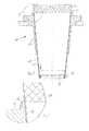
- the presentation of the Fig. 1shows a device 10 for producing a cup, wherein only a small section of the device is shown.
- the device 10has a conical receptacle 12, wherein, for example, a plurality of conical receptacles 12 can be arranged on the circumference of a star wheel.
- a conical sleeve 14is added, which is already connected to a pot-shaped bottom 16 in the region of a frame 18 is substantially liquid-tight.
- a subsequent to the lower edge of the sleeve 12 regionis turned over by 180 ° and in the envelope a wall of the cup-shaped bottom 16 is received.
- the region of the frame 18is then pressed to produce a substantially liquid-tight connection between the bottom 16 and sleeve 14.
- the sleeve 14is still provided with a circumferential stacking shoulder 20.
- another similar cupcan be stacked to avoid jamming a plurality of nesting cups.
- the receptacle 12has at its upper edge an annular recess 22, which later serves to form a mouth roll on the upper edge of the sleeve 14.
- a punch 24 in the in Fig. 1The large opening above the sleeve 14 is used to prepare the area surrounding the upper opening of the sleeve 14 for the formation of the mouth roll.
- the punch 24it is ensured that the upper edge of the sleeve 14 is substantially circular and can be formed in a subsequent process step to a mouth roll.
- the punch 24is made of porous material, such as felt, and also serves to coat the inside of the upper edge of the sleeve 14 with lubricant.
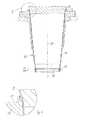
- Fig. 2is the detail II of the Fig. 1 to recognize in an enlarged view.
- the presentation of the Fig. 3shows one to the in Fig. 1 illustrated method step subsequent method step.
- a hood 26which is provided with channels 28, heated air is blown against the adjoining the upper edge of the sleeve 14 area.
- the hood 26surrounds the upper edge of the sleeve 14 and ensures that the heated air can not escape upwards.
- the heated airwill, see Fig. 4 , thereby blown through the channels 28 from the outside against the sleeve 14.
- a lubricantis applied to this area to facilitate subsequent molding of the mouth roll.
- the presentation of the Fig. 5shows the inventive device for producing a cup, after a punch 30 has been placed on the sleeve 14 for molding a mouth roll 32.
- the placement of the punch 30causes the upper edge of the sleeve 14 to be folded outwards and rolled in by about 270 ° to 360 °.
- the punch 30has this, see Fig. 6 , a circular, downwardly open groove 34. Together with the groove 22 in the receptacle 12, the groove 34 thereby forms a recess approximately circular in cross section, which leads to a curl of the upper edge of the sleeve 14 and thereby to the formation of the mouth roll 32 when advancing the punch 30 in the direction of the bottom 16.
- the punch 30can be delivered only axially to form the mouth roll 32 or additionally rotate about the central longitudinal axis 36 of the sleeve 14.
- the cup 38may now be provided with an outer sheath and / or an insulating layer, as appropriate, to be suitable for hot drinks.
- the described steps for producing the mouth rollallow the production of a mouth roll even with very stiff and / or thick paper material as well as with very stiff and / or thick paper-like plastic material to be processed.
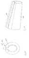
- the presentation of the Fig. 7shows a winding mandrel 40 in a schematic representation obliquely from above.
- the winding mandrel 40has an end 42 with a larger diameter and an end 44 with a smaller diameter.
- the winding mandrel 40is provided for producing a conical sleeve of a flat material segment.
- the flat material segmentis placed around the winding mandrel 40 and the longitudinal edges of the planar segment are superimposed in a region 46 of the winding mandrel 40. After the area of the overlap has then been joined together, a conical sleeve is created.
- Fig. 7can be seen, deviates a cross-sectional shape of the winding mandrel 40 from the circular shape.
- the region 46, on which the overlap of the segment edges of the planar segment is arranged,is made flattened.
- a front view of the winding mandrel 40clearly visible.
- the winding mandrel 40has a flattening in the region 46 of the later overlap of the segment edges in order to allow the production of a conical sleeve with a circular cross-section, even in very stiff paper material or very stiff paper-like plastic material to be processed, as in the 10 and 11 is shown.
- the Region of the overlapis twice the material thickness, behaves this area of the sleeve 14 after removal from the winding mandrel 40 differently than the rest of the area in which there is only the simple material thickness.
- the winding mandrelmay also be formed with an oval or elliptical cross-sectional shape, wherein the overlap of the segment edges is then arranged in a flat region of the oval or a portion of the ellipse with a larger diameter.
- FIG. 9shows the winding mandrel 40 with the applied sleeve 14 and a ram 48 in a schematic representation.
- the pressing punch 48is arranged opposite the region 46 of the winding mandrel 40, in which the overlapping of the segment edges comes to rest.
- the presentation of the Fig. 12shows a view of the winding mandrel 40 with the applied sleeve 14 and the ram 48 obliquely from above.
- Fig. 13shows the winding mandrel 40 with the ram 48 and the sleeve 14 from the front.
- Fig. 14shows a view on a sectional plane through the central longitudinal axis 36 of the winding mandrel 40 and the sleeve 14 from Fig. 12 . It is Fig. 14 it can be seen that the pressing ram 48, which extends along a surface line of the winding mandrel 40, in a region 50, which compresses a adjoining the upper edge of the sleeve 14 portion of the sleeve 14, and in a region 52, a to the Squeezing lower edge of the sleeve 14 subsequent region of the overlap, a smaller distance from the surface of the winding mandrel 40 than in its center region 54.
- the center region 54is thus opposite the regions 50, 52 excluded.
- FIG. 14shows a longitudinal section through the region of the overlap of the segment edges of the sleeve 14, the area of overlap by the ram 48 subsequent to the upper edge or lower edge of the sleeve 14 thereby receives a material thickness which deviates only slightly from the material thickness at the remaining circumference of the sleeve 14 and thereby reliably and reliably to a mouth roll 32 and a frame 18 can be transformed.
- the schematic representation of Fig. 14does not reflect these thickness ratios and serves only to explain the principle of operation.
- the areas 50, 52have a length which correspond to only about 10% of the total length of the ram 48.
- the force that must be exerted on the ram 48while the force is greater than conventional press dies, but the apparatus for making the cup need not be designed for excessively large pressing pressures that would be required when the areas 50, 52 over the entire length of the ram or over a larger area than in Fig. 14 would extend.
- the representations of the Fig. 16 to 27describe the insertion of the cup-shaped bottom 16 in the conical sleeve 14 and the turning over of the lower edge of the sleeve 14 and the subsequent molding of the frame 18th
- Fig. 16 1shows a schematic sectional view of an apparatus 110 for producing a cup from a conical sleeve 14 and a cup-shaped bottom 16.
- the apparatus 110may form part of a larger machine (not shown) and, for example, several of the apparatuses 110 may be arranged on a starwheel.
- the sleeve 14has been produced by winding and gluing or sealing in the region of a non-illustrated overlap of a flat segment.
- the pot-shaped bottom 16has also been produced from a flat segment.
- the sleeve 14is disposed on a likewise conical mandrel 116 which has a central guide bore in which a punch 118 is guided for holding the bottom 16.
- the punch 118has an actuating rod 120 and a stamp plate 121 with a stamp surface 122.
- the stamp surface 122is located at an in Fig. 1 overhead floor surface 130 of the bottom 16 at.
- This overhead bottom surface 130 of the bottom 16defines on the finished cup a lower boundary of the interior of the cup to be filled with liquid.
- a peripheral peripheral wall 24extends, which extends at right angles to the bottom surface.
- the bottom 16is replaced by a cup-like shape.
- the actuating rod 118is provided with a through bore 126. At the bore 126, a negative pressure is temporarily applied during the production process.
- the through-bore 126opens into the stamp surface 122, so that after applying a negative pressure to the bore 126, the bottom surface 130 of the bottom 16 is pulled against the stamp surface 122. The bottom 16 can thereby be safely inserted into the sleeve 14 without the risk of it falling off of the stamp surface 122.
- a blowing member 128adapted to blow warm air against the inside of the sleeve to facilitate the deformation of the sleeve and more specifically the turning of the lower end of the sleeve 14 about the peripheral wall 124 of the bottom 16.
- Radial warm air 129flows out of the blowing part 128 in order to heat the inside of the sleeve 14 in a region on which the circumferential wall 124 of the bottom 16 subsequently comes to lie.
- a sealable coating on the inside of the sleeve 14can be heated to then allow the peripheral wall 124 to be sealed, and thus a fluid-tight connection of peripheral wall 124 and sleeve 14.
- the enlarged detail XVII in Fig. 17lets first recognize the stamp surface 122, against which the bottom surface 130 of the bottom 16 is sucked.
- An outer side of the peripheral wall 124 of the bottom 16is covered in sections by an annular cover sleeve 132.
- the cover sleeve 132abuts against a radially outer peripheral surface of the peripheral wall 124 of the bottom 16.
- the cover sleeve 132prevents the radially outer surface of the peripheral wall 124 from coming into contact with an inner surface 134 of the sleeve 14 before a predefined relative position of the bottom 16 and sleeve 14 is reached.
- the annular cover sleeve 132is provided with an annular mounting plate 136 whose central bore is matched to the outer diameter of the actuating rod 118.
- the mounting plate 136 and the annular cover sleeve 132 integrally connected to the mounting plate 136can thus be moved relative to the punch 118.
- an underside of the mounting plate 136abuts on an upper side of the stamp plate 121. With its upper side, the attachment plate 136 bears against a surface of the mandrel 116.
- Fig. 17The punch 118 is moved together with the bottom 16 and the cover sleeve 132 down.
- the enlarged detail XIX Fig. 18is in Fig. 19 can be seen that the annular cover sleeve 132 now rests on the one hand on the inside of the sleeve 14 and on the other hand on the radially outer peripheral surface of the peripheral wall 124 of the bottom 16.
- the inner diameter of the cover sleeve 132can be dimensioned so that the bottom 16 is slightly compressed, so slightly rebounded after pulling out of the cover 132, so that then the peripheral wall 124 is substantially flat against the inside of the sleeve 14.
- the peripheral wall 124 of the bottom 16is in the state of Fig. 19 not on the inside of the sleeve 14, although the bottom 16 and the sleeve 14 are arranged in a relative position to each other, they also take on the finished cup to each other.
- This punch 144has a plurality of radially movable pressing jaws 146, which can be pressed radially outward by a centrally located actuating element 148.
- On the outside of the sleeve 14is in the region of the peripheral wall 124 of the bottom 16 on an outer side of the sleeve 14, a retaining ring 150 at.
- This retaining ring 50provides an abutment when the pressing jaws 146 are moved radially outward to urge the peripheral wall 124 against the inside 134 of the sleeve 14.
- FIG. 21shows the detail XXI of Fig. 20 in an enlarged view.
- the peripheral wall 24 of the bottom 16is now flat on the inside 134 of the sleeve 14, since the annular cover sleeve 132 has been pulled up between the peripheral wall 124 and the inside of the sleeve 14.
- the pressing jaws 146 and the retaining ring 150now provide for a compression of the peripheral wall 124 with the inner side 134 of the sleeve 14 and thereby for a liquid-tight connection of the bottom 16 with the sleeve 14th
- the presentation of the Fig. 22shows another, on the state of Fig. 20 or 21 following process step.
- the pressing jaws 146 and the retaining ring 150have been removed.
- the in Fig. 22is pushed from below onto the sleeve 14, a circumferential stacking shoulder 154 is inserted into the sleeve 14.
- This stacking shoulder 154serves to reliably stack several cups in each other.
- a certain counterweight when sliding the pressure ring 152provides the annular cover sleeve 132, which in the state of Fig. 22 is arranged radially inside the press ring 152.
- radially inwardly displaceable jaws 156ensure that the lower edge 158 of the sleeve is turned radially inward.
- the jaws 156are in FIGS. 22 and 23 shown in its radially inner end position.
- a the cover of the lower edge 158 of the sleeve 14 causing, radially inner edge of the jaw 156is provided with a chamfer 157, which runs at a movement of the jaws 156 according to the arrows 155 on the lower edge 158 of the sleeve 14 and the edge 158 to turns inside about 50 ° to 60 °.
- the rim 158is turned inwards over its entire circumference. Another turn of the edge 158, then approximately 180 ° is effected by a punch 160, which starting from the state of Fig. 22 is moved upward according to the arrow 161. The turning over of the lower edge 158 of the sleeve 14 is facilitated because, see Fig. 17 , the sleeve 14 has been previously heated in this envelope area.
- Fig. 23shows the detail XXIII of Fig. 22 in an enlarged view.
- Fig. 25shows the detail XXIV of the Figure 24 in an enlarged view.
- Fig. 26As in Fig. 26 is shown, starting from the state of Fig. 24 Then, the lower edge 158 of the sleeve 14 is pressed radially outward to form a so-called circumferential frame 162 at the lower end of the sleeve 14, see Fig. 26 , The frame 162 then forms the base for a finished cup.
- FIG. 27shows the enlarged detail XXVII Fig. 26 .
- Fig. 18 to 21allows the annular cover sleeve 132, the bottom 16 and the sleeve 14 relative to each other to position so that they have already reached the provided on the finished cup relative position without touching the bottom 16 and the inside of the sleeve 14.
- touchsee Fig. 19
- the radially outward surface of the peripheral wall 124 of the bottom 16 and the inside 134 of the sleeve 14are not until the predefined relative position is reached.
- a possible high coefficient of friction between the material or the surface of the bottom 16 and the inside of the sleeve 14thus does not hinder the manufacturing process of the cup.
- the peripheral wall 124 of the bottom 16 with its radially outer surfacecan create a flat against the inside of the sleeve 14. Since the inside of the sleeve 14 has been previously heated in this area, a liquid-tight connection of the bottom 16 and the sleeve 14 can take place immediately. This is supported by the radially outwardly moving pressing jaws 146.
- the presentation of the Fig. 28shows in a front view a winding mandrel 170.
- the winding mandrelOn the winding mandrel of the punch 48 is arranged.
- the winding mandrelhas a conical, generally elliptical basic shape with a flattening 172.
- the flatteningis arranged at a location of the generally elliptical cross section, in which a smaller radius of curvature of the ellipse would be arranged in and of itself.
- the overlap of the segment edgesis arranged.
- the special shape of the winding mandrel 170makes it possible, even with very stiff sheet-like paper materials or sheet-like plastic materials, to produce a sleeve with a circular cross-section after removal of the finished conical sleeve.
- the Fig. 29shows the winding mandrel 170 in a view obliquely from above together with the ram 48th
- the presentation of the Fig. 30shows a front view of a winding mandrel 174 according to another embodiment of the invention.
- the winding mandrel 174has an elliptical cross-sectional shape and is conical.
- On the winding mandrel of the ram 48can be seen.
- the ram 48is located in the middle of a region of the elliptical cross section in which the larger radius of curvature of the ellipse is present. Also in this way it can be achieved that when winding a sleeve of stiff paper material or rigid plastic material after removal of the finished sleeve, the sleeve assumes a circular shape.
- the cross-sectional shape of the winding mandrel 174may also be formed oval.
- the cross-sectional shapewould then be characterized in that it has a flat portion approximately in the region in which the ram 48 is arranged, and also opposite. Even with such a winding mandrel with an oval cross-section can be achieved that a manufactured sleeve after peeling has the shape of a circular truncated cone.
- FIG. 31shows the winding mandrel 174 with the ram 48 obliquely from above.
Landscapes
- Making Paper Articles (AREA)
- Engineering & Computer Science (AREA)
- Mechanical Engineering (AREA)
Abstract
Translated fromGermanDescription
Translated fromGermanDie Erfindung betrifft ein Verfahren zum Herstellen eines Bechers aus einem flächigen Segment und einem topfförmigen Boden sowie eine Vorrichtung zum Herstellen eines solchen Bechers.The invention relates to a method for producing a cup from a flat segment and a cup-shaped bottom and to an apparatus for producing such a cup.
Mit der Erfindung sollen ein Verfahren und eine Vorrichtung zum Herstellen eines Bechers verbessert werden.With the invention, a method and an apparatus for producing a cup are to be improved.
Erfindungsgemäß ist hierzu ein Verfahren mit den Merkmalen von Anspruch 1 bzw. eine Vorrichtung mit den Merkmalen von Anspruch 11 vorgesehen. Vorteilhafte Weiterbildungen der Erfindung sind in den Unteransprüchen angegeben.According to the invention, a method with the features of claim 1 or a device with the features of claim 11 is provided for this purpose. Advantageous developments of the invention are specified in the subclaims.
Erfindungsgemäß ist bei einem Verfahren zum Herstellen eines Bechers aus einem flächigen Segment und einem topfförmigen Boden das Wickeln des flächigen Segments auf einen Wickeldorn, so dass im Bereich der Seitenkanten des Segments eine Überlappung vorliegt, das Verbinden der an die Seitenkanten anschließenden Abschnitte im Bereich der Überlappung, so dass eine konische Hülse entsteht, das Einsetzen des topfförmigen Bodens in die konische Hülse und das im Wesentlichen flüssigkeitsdichte Verbinden einer umlaufenden Wandung des topfförmigen Bodens mit einer Innenseite der Hülse vorgesehen.According to the invention, in a method for producing a cup from a flat segment and a pot-shaped bottom, the winding of the planar segment onto a winding mandrel so that an overlap exists in the region of the side edges of the segment, the joining of the sections adjoining the side edges in the region of the overlap , so that a conical sleeve is formed, the insertion of the cup-shaped bottom into the conical sleeve and the substantially liquid-tight connection of a circumferential wall of the cup-shaped bottom provided with an inner side of the sleeve.
Das erfindungsgemäße Verfahren ist für Papiermaterial und papierähnlich zu verarbeitende Materialien vorgesehen. Beispielsweise kann Papier, Karton oder Pappe in flächigen Segmenten vorliegen und diese flächigen Segmente können dann einerseits zu einer konischen Hülse gewickelt und andererseits zu einem topfförmigen Boden verformt werden. Zweckmäßigerweise ist das Papiermaterial flüssigkeitsdicht beschichtet. In gleicher Weise oder zumindest ähnlicher Weise wie Papiermaterial werden auch flächig vorliegende Kunststoffmaterialien zu Bechern verarbeitet. Flächige Kunststoffmaterialien sind beispielsweise auch Kunststofflaminate. Dabei wird das flächige Kunststoffmaterial, das in Segmentform vorliegt, ebenfalls um einen Wickeldorn gewickelt und im Bereich der Überlappung verbunden, um eine konische Hülse zu formen. Auch ein topfförmiger Boden kann aus dem flächigen Kunststoffmaterial geformt werden, indem ein kreisförmiger Zuschnitt in seinem Randbereich gegenüber einer Bodenfläche etwa senkrecht nach oben geklappt wird. Die Probleme, die bei papierähnlich zu verarbeitendem Kunststoffmaterial auftreten, sind dabei im Wesentlichen die gleichen, die beim Verarbeiten von Papiermaterial auftreten. Die vorliegende Erfindung kann für papierähnlich zu verarbeitende Kunststoffmaterialien eingesetzt werden, sie ist aber nicht speziell für papierähnlich zu verarbeitende Kunststoffmaterialien ausgebildet, sondern kann vielmehr mit erheblichen Vorteilen auch für Papiermaterial eingesetzt werden, speziell wenn das Papiermaterial beispielsweise aus einer sehr steifen und/oder dicken Pappe besteht.The method according to the invention is intended for paper material and paper-like materials to be processed. For example, paper, cardboard or cardboard can be present in planar segments and these flat segments can then be wound on the one hand to a conical sleeve and on the other hand deformed into a cup-shaped bottom. Conveniently, the paper material is coated liquid-tight. In the same way, or at least as similar as paper material and plastic materials are surface-widely processed into cups. Flat plastic materials are, for example, also plastic laminates. In this case, the sheet-like plastic material, which is in segmental form, is also wound around a mandrel and connected in the region of the overlap to form a conical sleeve. Also, a pot-shaped bottom can be formed from the sheet-like plastic material by a circular blank is folded in its edge region opposite a bottom surface approximately vertically upwards. The problems that occur in paper-like plastic material to be processed, are thereby substantially the same, which occur during the processing of paper material. The present invention can be used for paper-like plastic materials to be processed, but it is not specifically designed for paper-like plastic materials to be processed, but rather, with considerable advantages as well be used for paper material, especially if the paper material consists for example of a very stiff and / or thick cardboard.
In Weiterbildung der Erfindung wird beim Verbinden der an die Seitenkanten anschließenden Abschnitte im Bereich der Überlappung ein Pressdruck ausgeübt, wobei der Pressdruck in den Bereichen, die sich unmittelbar an die Unterkante der Hülse und die Oberkante der Hülse anschließen, größer ist als in den übrigen Bereichen der Überlappung.In a further development of the invention, a pressing pressure is exerted in the region of the overlap when joining the sections adjoining the side edges, wherein the pressing pressure in the regions which adjoin the lower edge of the sleeve and the upper edge of the sleeve is greater than in the other regions the overlap.
Erfindungsgemäß ist also vorgesehen, im Bereich der Unterkante und der Oberkante der Hülse das Papiermaterial oder papierähnlich zu verarbeitende Material stärker zusammenzudrücken als im Mittenbereich. Gerade bei vergleichsweise dicken Materialien wird dadurch das nachfolgende Umformen der Unterkante und der Oberkante der Hülse zu einer Mundrolle bzw. einer Zarge erheblich erleichtert.According to the invention, therefore, it is provided to compress the paper material or paper-like material to be processed more strongly in the region of the lower edge and the upper edge of the sleeve than in the middle region. Especially with comparatively thick materials thereby the subsequent forming of the lower edge and the upper edge of the sleeve to a mouth roll or a frame is considerably facilitated.
In Weiterbildung der Erfindung ist die Länge des Bereichs, der sich unmittelbar an die Unterkante der konischen Hülse anschließt, so groß gewählt, dass der Bereich sich am fertiggestellten Becher wenigstens über die Außenseite und Innenseite einer Zarge erstreckt, mit der der Boden und die Hülse im Wesentlichen flüssigkeitsdicht verbunden sind.In a further development of the invention, the length of the region which adjoins directly to the lower edge of the conical sleeve, chosen so large that the area extends to the finished cup at least on the outside and inside of a frame with which the bottom and the sleeve in the Are connected substantially liquid-tight.
Zum Herstellen einer Zarge wird in der Regel die Hülse um 180° nach innen umgeschlagen und die Wandung des topfförmigen Bodens wird in diesem Umschlag aufgenommen. Zum flüssigkeitsdichten Verbinden werden dann Hülse und Boden im Bereich der Zarge verpresst und/oder stoffschlüssig verbunden. Wenn der Bereich der Überlappung an der Unterkante der Hülse stärker verpresst wird als im Mittenbereich und somit die Überlappung im Bereich der späteren Zarge flacher ist als im Mittenbereich, ist die Herstellung der Zarge erheblich erleichtert.To produce a frame, the sleeve is generally turned through 180 ° inwards and the wall of the cup-shaped bottom is received in this envelope. For liquid-tight bonding then sleeve and bottom are pressed in the region of the frame and / or materially connected. If the region of the overlap at the lower edge of the sleeve is pressed more strongly than in the middle region and thus the overlap in the region of the later frame is flatter than in the middle region, the production of the frame is considerably facilitated.
In Weiterbildung der Erfindung wird die Länge des Bereichs, der sich unmittelbar an die Oberkante der konischen Hülse anschließt, so groß gewählt, dass der Bereich sich am fertiggestellten Becher wenigstens über die Mundrolle erstreckt.In a development of the invention, the length of the region which adjoins directly to the upper edge of the conical sleeve is chosen to be so large that the region extends at least over the mouth roll on the finished cup.
Im Bereich der Mundrolle erleichtert die gegenüber dem Mittenbereich stärker flachgepresste Überlappung das Herstellen der Mundrolle erheblich. An und für sich könnte natürlich der vollständige Bereich der Überlappung stark zusammengepresst werden. Die hierfür erforderlichen Pressdrücke sind aber so hoch, dass sie eine erhebliche Verstärkung der für die Herstellung von Bechern aus Papiermaterial und papierähnlich zu verarbeitendem Material verwendeten Vorrichtung oder Maschine erfordern würden. Durch das stärkere Pressen der Überlappung lediglich im Bereich der Oberkante und Unterkante der Hülse können dadurch auch sehr dicke Papiermaterialien oder papierähnlich zu verarbeitende Kunststoffmaterialien problemlos verarbeitet werden, ohne große Veränderungen an der Maschine selbst zu erfordern.In the area of the mouth roll, the overlapping which is pressed over the center area more strongly facilitates the production of the mouth roll considerably. In and of itself, of course, the full range of overlap could be severely compressed. However, the required compressive pressures are so high that they would require a substantial increase in the apparatus or machine used to make cups of paper material and paper-like material to be processed. Due to the stronger pressing of the overlap only in the region of the upper edge and lower edge of the sleeve can also be very thick Paper materials or paper-like plastic materials to be processed without difficulty, without requiring major changes to the machine itself.
In Weiterbildung der Erfindung wird das flächige Segment zum Herstellen der konischen Hülse auf einen Wickeldorn aufgewickelt, dessen Querschnitt von einer Kreisform abweicht und entweder oval, elliptisch oder im Bereich der Überlappung der Segmentkanten abgeplattet ist.In a further development of the invention, the flat segment for producing the conical sleeve is wound onto a winding mandrel whose cross section deviates from a circular shape and is flattened either oval, elliptical or in the region of the overlap of the segment edges.
Bei sehr steifen Papiermaterialien oder papierähnlich zu verarbeitenden Kunststoffmaterialien kommt es bei Verwendung eines Wickeldorns mit kreisrundem Querschnitt nach dem Abziehen der Hülse vom Wickeldorn zu einer Verformung der Hülse in eine Querschnittsform, die von der Kreisform abweicht. Dies ist durch die doppelte Materiallage im Bereich der Überlappung verursacht. Selbst dann, wenn der Bereich der Überlappung durch Temperatureinwirkung versiegelt wird, wird die kreisrunde Form nach dem Abstreifen vom Wickeldorn nicht beibehalten. Abhilfe kann hier in überraschend einfacher Weise ein Wickeldorn mit nicht kreisförmigem Querschnitt schaffen. Beispielsweise kann der Wickeldorn oval oder elliptisch ausgebildet sein, wobei der Bereich der Überlappung dann auf einem ebenen Abschnitt des Wickeldorns oder einem Abschnitt des Wickeldorns mit größerem Krümmungsradius angeordnet wird. Alternativ kann der Wickeldorn lediglich im Bereich der Überlappung von der Kreisform abweichen und im Bereich der Überlappung abgeplattet sein. Auch bei sehr steifem Papiermaterial und sehr steifem papierähnlich zu verarbeitendem Kunststoffmaterial nimmt die Hülse nach dem Abstreifen vom Wickeldorn dann eine Form mit kreisförmigem Querschnitt ein.For very stiff paper materials or paper-like plastic materials to be processed when using a winding mandrel having a circular cross-section after pulling off the sleeve from the mandrel to a deformation of the sleeve in a cross-sectional shape that deviates from the circular shape. This is caused by the double material layer in the area of the overlap. Even if the area of the overlap is sealed by the action of temperature, the circular shape after stripping from the winding mandrel is not maintained. Remedy can create a winding mandrel with non-circular cross section here in a surprisingly simple way. For example, the winding mandrel may be formed oval or elliptical, wherein the region of the overlap is then arranged on a flat portion of the winding mandrel or a portion of the winding mandrel with a larger radius of curvature. Alternatively, the mandrel may deviate from the circular shape only in the region of the overlap and be flattened in the region of the overlap. Even with very stiff paper material and very stiff paper-like plastic material to be processed takes the sleeve after stripping the winding mandrel then a shape with a circular cross section.
In Weiterbildung der Erfindung wird zum Ausüben des Pressdrucks ein Pressstempel verwendet, der im Mittenbereich weiter vom Wickeldorn beabstandet ist als in seinen beiden Endbereichen.In a further development of the invention, a pressing punch is used for exerting the pressing pressure, which is spaced further from the winding mandrel in the middle region than in its two end regions.
Mit einem solchen Pressstempel lässt sich der im Bereich der Unterkante und der Oberkante der Hülse größere Pressdruck auf einfache Weise verwirklichen.With such a ram, the greater pressure in the region of the lower edge and the upper edge of the sleeve can be realized in a simple manner.
In Weiterbildung der Erfindung ist das Umschlagen eines unteren Randes der Hülse, der über die untere Kante der Umfangswandung des Bodens hinausragt, mittels mehrerer, in radialer Richtung verschiebbarer Backen nach innen vorgesehen, bis der untere Rand zur Mittellängsachse der Hülse eine vordefinierte erste Winkelposition einnimmt.In a further development of the invention, the turning over of a lower edge of the sleeve, which projects beyond the lower edge of the peripheral wall of the bottom, provided by means of several radially displaceable jaws inward until the lower edge to the central longitudinal axis of the sleeve occupies a predefined first angular position.
Gerade sehr steifes Papiermaterial oder sehr steifes flächiges Kunststoffmaterial kann durch diese Maßnahmen am unteren Rand der Hülse sehr präzise und zuverlässig umgeschlagen werden. Im Gegensatz zu üblichen Verfahren bei der Becherherstellung, bei denen der Umschlag des unteren Randes der Hülse durch die Zustellung eines Stempels parallel zur Mittellängsachse der Hülse erfolgt, wird durch die erfindungsgemäß vorgesehenen radial verschiebbaren Backen ein Ausknicken des unteren Randes der Hülse beim Umschlagen zuverlässig verhindert. Das Umschlagen des unteres Randes, dass einen Teilschritt der Herstellung der unteren, umlaufenden Zarge zur Verbindung von Hülse und Boden bildet, kann damit mit sehr kurzen Taktzeiten und in prozesssicherer Weise erfolgen.Especially very stiff paper material or very rigid plastic sheet material can be handled very precisely and reliably by these measures at the bottom of the sleeve. In contrast to conventional methods in the cup making, where the envelope the lower edge of the sleeve is effected by the delivery of a punch parallel to the central longitudinal axis of the sleeve, is reliably prevented by the inventively provided radially movable jaws buckling of the lower edge of the sleeve during turnover. The turning over of the lower edge, which forms a partial step in the production of the lower, circumferential frame for connecting the sleeve and the base, can thus take place with very short cycle times and in a process-reliable manner.
In Weiterbildung der Erfindung wird ausgehend von der ersten Winkelposition der untere Rand der Hülse mittels eines parallel zur Mittellängsachse der Hülse bewegbaren Stempels in eine zweite vordefinierte Winkelposition umgeschlagen.In a further development of the invention, starting from the first angular position of the lower edge of the sleeve is moved by means of a parallel to the central longitudinal axis of the sleeve movable punch in a second predefined angular position.
Nachdem der untere Rand durch die radial nach innen verschiebbaren Backen in die vordefinierte erste Winkelposition gebracht ist, in der der untere Rand beispielsweise einen Winkel zwischen 50° und 60° zur Mittellängsachse einnimmt, besteht die Gefahr des Ausknickens beim weiteren Umschlagen des Randes nicht mehr und der weitere Umschlag des Randes, beispielsweise bis in eine zweite Winkelposition, in der der Rand einen Winkel von etwa 180° zur Mittellängsachse einnimmt, kann in bewährter Weise mittels eines parallel zur Mittellängsachse zustellbaren Stempels erfolgen.After the lower edge is brought by the radially inwardly displaceable jaws in the predefined first angular position in which the lower edge, for example, assumes an angle between 50 ° and 60 ° to the central longitudinal axis, there is no longer the risk of buckling in the further turning of the edge and the further turn of the edge, for example, into a second angular position in which the edge occupies an angle of about 180 ° to the central longitudinal axis, can be done in a proven manner by means of a parallel deliverable to the central longitudinal axis punch.
Bei der Erfindung ist das Einbringen einer ersten rillenförmigen Vertiefung in das flächige Segment oder in die konische Hülse, wobei die erste rillenförmige Vertiefung in einem konstanten Abstand zu einer kürzeren Unterkante des Segments bzw. einer Unterkante der Hülse verläuft, und das Umschlagen der Hülse um die erste rillenförmige Vertiefung zur Bildung einer Zarge mit der umlaufenden Wandung des topfförmigen Bodens vorgesehen, so dass ein Bereich um die erste rillenförmige Vertiefung im vollständig umgeschlagenen Zustand der Hülse eine Standfläche des Bechers bildet.In the invention, the introduction of a first groove-shaped depression in the planar segment or in the conical sleeve, wherein the first groove-shaped recess extends at a constant distance to a shorter lower edge of the segment or a lower edge of the sleeve, and the turning of the sleeve to the first groove-shaped recess for forming a frame with the circumferential wall of the cup-shaped bottom provided, so that an area around the first groove-shaped recess in the fully folded state of the sleeve forms a base of the cup.
Gerade bei sehr dickem und dadurch steifem Papiermaterial ist das Vorprägen des Bereichs, in dem später die Zarge ausgeformt wird, von großem Vorteil. Das Vorprägen des Materials kann dabei entweder am flächigen Segment oder erst an der fertiggestellten Hülse erfolgen.Especially with very thick and thus stiff paper material is the pre-embossing of the area in which later the frame is formed, of great advantage. The pre-embossing of the material can be done either on the flat segment or only on the finished sleeve.
Bei der Erfindung ist das Einprägen von mehreren zweiten, rillenförmigen Vertiefungen vorgesehen, die nebeneinander liegen und die sich von der ersten rillenförmigen Vertiefung aus bis zur Unterkante des Segments oder der Unterkante der Hülse erstrecken.In the invention, the embossing of a plurality of second, groove-shaped depressions is provided, which lie next to one another and which extend from the first groove-shaped depression to the lower edge of the segment or the lower edge of the sleeve.
In Weiterbildung der Erfindung ist das Anwärmen des Materials der Hülse im Bereich der Oberkante der Hülse und das anschließende Formen der Mundrolle vorgesehen.In a further development of the invention, the heating of the material of the sleeve in the region of the upper edge of the sleeve and the subsequent shaping of the mouth roll is provided.
Auf diese Weise kann gerade bei sehr steifem Papiermaterial oder papierähnlich zu verarbeitendem Kunststoffmaterial das Formen der Mundrolle erleichtert werden. Überraschenderweise ist auch bei Papiermaterial das Anwärmen des Materials vor dem Formen der Mundrolle hilfreich. Es muss selbstverständlich darauf geachtet werden, dass das Papiermaterial dabei nicht Feuer fängt.In this way, especially with very stiff paper material or paper-like plastic material to be processed, the shaping of the mouth roll can be facilitated. Surprisingly, warming up of the material prior to molding the mouth roll is also helpful with paper material. It must of course be taken to ensure that the paper material does not catch fire.
In Weiterbildung der Erfindung sind das Auftragen von Gleitmittel im Bereich der Oberkante der Hülse und das anschließende Formen der Mundrolle vorgesehen.In a further development of the invention, the application of lubricant in the region of the upper edge of the sleeve and the subsequent shaping of the mouth roll are provided.
Das der Erfindung zugrundeliegende Problem wird auch durch eine Vorrichtung zum Herstellen eines Bechers mit einem sich einseitig verjüngenden Wickeldorn gelöst, bei dem ein Querschnitt des Wickeldorns von einer Kreisform abweicht und entweder oval, elliptisch oder im Bereich der Überlappung der Segmentkanten abgeplattet ist.The problem underlying the invention is also solved by a device for producing a cup having a winding mandrel which tapers on one side, in which a cross section of the mandrel deviates from a circular shape and is flattened either oval, elliptical or in the region of the overlap of the segment edges.
Überraschenderweise kann durch einen solchen, von einer Kreisform abweichenden Wickeldorn bei sehr steifem Papiermaterial oder sehr steifem papierähnlich zu verarbeitendem Kunststoffmaterial eine kreisförmige Hülse hergestellt werden. Durch die Überlappung bei der Herstellung der Hülse ist die Hülse im Bereich der Überlappung deutlich steifer, da dort die doppelte Materialdicke vorliegt. Durch einen ovalen oder im Bereich der Überlappung der Segmentkanten abgeplatteten Wickeldorn verformt sich die Hülse beim Abziehen vom Wickeldorn so, dass sie eine im Querschnitt kreisrunde Form erhält.Surprisingly, by means of such a winding mandrel deviating from a circular shape in the case of very stiff paper material or very stiff paper-like plastic material to be processed, a circular sleeve can be produced. Due to the overlap in the production of the sleeve, the sleeve is significantly stiffer in the region of the overlap, since there is twice the material thickness. By an oval or in the region of the overlap of the segment edges flattened winding mandrel, the sleeve deformed during removal from the winding mandrel so that it receives a circular cross-sectional shape.
In Weiterbildung der Erfindung sind bei der Vorrichtung zum Herstellen eines Bechers ein Wickeldorn und ein Pressstempel vorgesehen, wobei der Pressstempel sich entlang einer Mantellinie des Wickeldorns erstreckt und wobei der Pressstempel in einem, auf den Wickeldorn aufgesetzten Zustand, in seinem Mittenbereich weiter vom Wickeldorn beabstandet ist als in seinen beiden Endbereichen.In a further development of the invention, a winding mandrel and a press die are provided in the apparatus for producing a cup, wherein the press ram extends along a generatrix of the winding mandrel and wherein the press ram is spaced further apart from the winding mandrel in a state placed on the winding mandrel in its center region as in its two end regions.
Durch einen solchen Pressstempel kann der Bereich der Überlappung an der Unterkante und Oberkante der Hülse auf einfache Weise stärker gepresst werden, wodurch im Bereich der Oberkante und Unterkante der Hülse die Wandungsdicke der Hülse an der Überlappung verringert wird. Dies erleichtert das nachfolgende Ausformen einer Mundrolle an der Oberkante der Hülse bzw. einer Zarge an der Unterkante der Hülse erheblich.By means of such a ram, the region of the overlap at the lower edge and upper edge of the sleeve can be pressed more easily in a simple manner, whereby the wall thickness of the sleeve at the overlap is reduced in the region of the upper edge and lower edge of the sleeve. This considerably facilitates the subsequent shaping of a mouth roll on the upper edge of the sleeve or a frame on the lower edge of the sleeve.
Weitere Merkmale und Vorteile der Erfindung ergeben sich aus den Ansprüchen und der folgenden Beschreibung bevorzugter Ausführungsformen der Erfindung im Zusammenhang mit den Zeichnungen. Einzelmerkmale der unterschiedlichen, in den Zeichnungen dargestellten Ausführungsformen lassen sich dabei in beliebiger Weise kombinieren, ohne den Rahmen der Erfindung zu überschreiten. In den Zeichnungen zeigen:
- Fig. 1
- eine schematische Schnittansicht einer Vorrichtung zum Herstellen eines Bechers beim Ausführen eines ersten Verfahrensschritts,
- Fig. 2
- die vergrößerte Einzelheit II aus
Fig. 1 , - Fig. 3
- die Vorrichtung zum Herstellen eines Bechers beim Ausführen eines zweiten Verfahrensschritts,
- Fig. 4
- die vergrößerte Einzelheit IV der
Fig. 3 , - Fig. 5
- die erfindungsgemäße Vorrichtung zum Herstellen eines Bechers beim Ausführen eines dritten Verfahrensschritts,
- Fig. 6
- die Einzelheit VI aus
Fig. 5 , - Fig. 7
- eine Ansicht eines Wickeldorns der erfindungsgemäßen Vorrichtung von schräg oben,
- Fig. 8
- den Wickeldorn der
Fig. 7 in einer Ansicht von vorne, - Fig. 9
- den Wickeldorn der
Fig. 7 und 8 mit aufgesetztem Pressstempel und aufgeschobener Hülse, - Fig. 10
- eine mit dem Wickeldorn der
Fig. 7 hergestellte Hülse nach dem Abziehen vom Wickeldorn, - Fig. 11
- eine Vorderansicht der Hülse der
Fig. 10 , - Fig. 12
- eine schematische Darstellung des Wickeldorns der
Fig. 9 von schräg oben, - Fig. 13
- den Wickeldorn der
Fig. 12 in einer Vorderansicht, - Fig. 14
- den Wickeldorn der
Fig. 12 in einem Längsschnitt, - Fig. 15
- die vergrößerte Einzelheit XV aus
Fig. 14 , - Fig. 16
- die Vorrichtung zum Herstellen eines Bechers beim Ausführen eines weiteren Verfahrensschritts,
- Fig. 17
- die vergrößerte Darstellung der Einzelheit XVII aus
Fig. 16 , - Fig. 18
- die Vorrichtung zur Herstellung eines Bechers beim Ausführen eines weiteren Verfahrensschritts,
- Fig. 19
- die vergrößerte Einzelheit XIX der
Fig. 18 , - Fig. 20
- die Vorrichtung zur Herstellung eines Bechers beim Ausführen eines weiteren Verfahrensschritts,
- Fig. 21
- eine vergrößerte Darstellung der Einzelheit XXI der
Fig. 20 , - Fig. 22
- die Vorrichtung zum Herstellen eines Bechers beim Ausführen eines weiteren Verfahrensschritts,
- Fig. 23
- die vergrößerte Einzelheit XXIII aus
Fig. 22 , - Fig. 24
- die Vorrichtung zum Herstellen eines Bechers beim Ausführen eines weiteren Verfahrensschritts,
- Fig. 25
- die vergrößerte Einzelheit XXV der
Fig. 24 , - Fig. 26
- die Vorrichtung zum Herstellen eines Bechers beim Ausführen eines weiteren Verfahrensschritts,
- Fig. 27
- die vergrößerte Einzelheit XXVII aus
Fig. 26 , - Fig. 28
- eine Vorderansicht eines Wickeldorns der erfindungsgemäßen Vorrichtung gemäß einer weiteren Ausführungsform,
- Fig. 29
- den Wickeldorn der
Fig. 28 von schräg oben, - Fig. 30
- eine Vorderansicht eines Wickeldorns der erfindungsgemäßen Vorrichtung gemäß einer weiteren Ausführungsform und
- Fig. 31
- den Wickeldorn der
Fig. 30 von schräg oben.
- Fig. 1
- FIG. 2 a schematic sectional view of an apparatus for producing a cup when carrying out a first method step, FIG.
- Fig. 2
- the enlarged detail II
Fig. 1 . - Fig. 3
- the device for producing a cup when carrying out a second method step,
- Fig. 4
- the enlarged detail IV of the
Fig. 3 . - Fig. 5
- the device according to the invention for producing a cup when carrying out a third method step,
- Fig. 6
- the detail VI
Fig. 5 . - Fig. 7
- a view of a winding mandrel of the device according to the invention obliquely from above,
- Fig. 8
- the mandrel of the
Fig. 7 in a view from the front, - Fig. 9
- the mandrel of the
FIGS. 7 and 8 with attached punch and pushed sleeve, - Fig. 10
- one with the mandrel of the
Fig. 7 manufactured sleeve after removal from the winding mandrel, - Fig. 11
- a front view of the sleeve of
Fig. 10 . - Fig. 12
- a schematic representation of the winding mandrel of
Fig. 9 from diagonally above, - Fig. 13
- the mandrel of the
Fig. 12 in a front view, - Fig. 14
- the mandrel of the
Fig. 12 in a longitudinal section, - Fig. 15
- the enlarged detail XV
Fig. 14 . - Fig. 16
- the device for producing a cup when carrying out a further method step,
- Fig. 17
- the enlarged view of detail XVII
Fig. 16 . - Fig. 18
- the device for producing a cup when carrying out a further method step,
- Fig. 19
- the enlarged detail XIX the
Fig. 18 . - Fig. 20
- the device for producing a cup when carrying out a further method step,
- Fig. 21
- an enlarged view of detail XXI of
Fig. 20 . - Fig. 22
- the device for producing a cup when carrying out a further method step,
- Fig. 23
- the enlarged detail XXIII
Fig. 22 . - Fig. 24
- the device for producing a cup when carrying out a further method step,
- Fig. 25
- the enlarged detail XXV the
Fig. 24 . - Fig. 26
- the device for producing a cup when carrying out a further method step,
- Fig. 27
- the enlarged detail XXVII
Fig. 26 . - Fig. 28
- a front view of a winding mandrel of the device according to the invention according to another embodiment,
- Fig. 29
- the mandrel of the
Fig. 28 from diagonally above, - Fig. 30
- a front view of a winding mandrel of the device according to the invention according to another embodiment and
- Fig. 31
- the mandrel of the
Fig. 30 from diagonally above.
Die Darstellung der
Die Aufnahme 12 weist an ihrem oberen Rand eine ringförmige Vertiefung 22 auf, die später zum Ausformen einer Mundrolle an der Oberkante der Hülse 14 dient. Bei dem in
In
Die Darstellung der
Die Darstellung der
Nach Abschluss des in
Die beschriebenen Schritte zur Herstellung der Mundrolle ermöglichen das Herstellen einer Mundrolle auch bei sehr steifem und/oder dickem Papiermaterial sowie auch bei sehr steifem und/oder dickem papierähnlich zu verarbeitenden Kunststoffmaterial.The described steps for producing the mouth roll allow the production of a mouth roll even with very stiff and / or thick paper material as well as with very stiff and / or thick paper-like plastic material to be processed.
Die Darstellung der
Alternativ zu der in den
Die Darstellung der
Die Darstellung der
Da lediglich die beiden Bereiche 50, 52 stärker zusammengedrückt werden, steigt die erforderliche Presskraft nicht zu stark an. Die Bereiche 50, 52 haben dabei eine Länge, die jeweils lediglich etwa 10% der Gesamtlänge des Pressstempels 48 entsprechen. Dadurch wird die Kraft, die auf den Pressstempel 48 ausgeübt werden muss, zwar größer als bei konventionellen Pressstempeln, dennoch muss aber die Vorrichtung zur Herstellung des Bechers nicht auf übermäßig große Pressdrücke ausgelegt werden, die erforderlich wären, wenn sich die Bereiche 50, 52 über die gesamte Länge des Pressstempels oder über einen größeren Bereich als in
Die Darstellungen der
Die Hülse 14 ist durch Wickeln und Verkleben bzw. Versiegeln im Bereich einer nicht dargestellten Überlappung aus einem flächigen Segment hergestellt worden. Der topfförmige Boden 16 ist ebenfalls aus einem flächigen Segment hergestellt worden. Die Hülse 14 ist auf einem ebenfalls konischen Dorn 116 angeordnet, der eine zentrale Führungsbohrung aufweist, in der ein Stempel 118 zum Halten des Bodens 16 geführt ist. Der Stempel 118 weist eine Betätigungsstange 120 und eine Stempelplatte 121 mit einer Stempelfläche 122 auf. Die Stempelfläche 122 liegt an einer in
Die Betätigungsstange 118 ist mit einer durchgehenden Bohrung 126 versehen. An die Bohrung 126 wird während des Produktionsprozesses zeitweise ein Unterdruck angelegt. Die Durchgangsbohrung 126 mündet in der Stempelfläche 122, so dass nach Anlegen eines Unterdrucks an die Bohrung 126 die Bodenfläche 130 des Bodens 16 gegen die Stempelfläche 122 gezogen wird. Der Boden 16 kann dadurch sicher und ohne die Gefahr, dass er von der Stempelfläche 122 abfällt, in die Hülse 14 eingeschoben werden.The
In der Darstellung der
Unterhalb des Bodens 16 ist ein Blasteil 128 angeordnet, der dazu vorgesehen ist, warme Luft gegen die Innenseite der Hülse zu blasen, um die Verformung der Hülse und speziell das Umschlagen des unteren Endes der Hülse 14 um die Umfangswand 124 des Bodens 16 zu erleichtern. Aus dem Blasteil 128 strömt radial warme Luft 129 ausströmt, um die Innenseite der Hülse 14 in einem Bereich zu erwärmen, auf dem nachfolgend die Umfangswandung 124 des Bodens 16 zu liegen kommt. Beispielsweise kann eine siegelfähige Beschichtung der Innenseite der Hülse 14 erwärmt werden, um dann ein Ansiegeln der Umfangswand 124 und damit eine flüssigkeitsdichte Verbindung von Umfangswand 124 und Hülse 14 zu ermöglichen.Below the bottom 16 there is disposed a blowing
Die vergrößerte Einzelheit XVII in
Die ringförmige Abdeckhülse 132 ist mit einer kreisringförmigen Befestigungsplatte 136 versehen, deren mittige Bohrung auf den Außendurchmesser der Betätigungsstange 118 abgestimmt ist. Die Befestigungsplatte 136 und die einstückig mit der Befestigungsplatte 136 verbundene ringförmige Abdeckhülse 132 können damit relativ zum Stempel 118 verschoben werden. In dem Zustand der
Ausgehend von dem Zustand der
Dieser Zustand ist dann in
Es ist in
Die vergrößerte Einzelheit XIX aus
Ausgehend vom Zustand der
Wesentlich ist, dass zum Verpressen der Umfangswand 124 und der Innenseite der Hülse 14, die ausgehend von dem Zustand der
Die Darstellung der
Die Darstellung der
Die Darstellung der
Ausgehend vom Zustand der
Wie in
Die Darstellung der
Wie vor allem anhand der
Die Darstellung der
Die
Die Darstellung der
Die Querschnittsform des Wickeldorns 174 kann auch oval ausgebildet sein. Die Querschnittsform wäre dann dadurch gekennzeichnet, dass sie etwa in dem Bereich, in dem der Presstempel 48 angeordnet ist, sowie auch gegenüber, einen ebenen Abschnitt aufweist. Auch mit einem solchen Wickeldorn mit ovalem Querschnitt lässt sich erreichen, dass eine hergestellte Hülse nach dem Abziehen die Form eines Kreiskegelstumpfes aufweist.The cross-sectional shape of the winding
Die Darstellung der
Claims (12)
Translated fromGermanApplications Claiming Priority (1)
| Application Number | Priority Date | Filing Date | Title |
|---|---|---|---|
| DE102014210960.4ADE102014210960A1 (en) | 2014-06-06 | 2014-06-06 | Method of making a cup |
Publications (2)
| Publication Number | Publication Date |
|---|---|
| EP2952340A1true EP2952340A1 (en) | 2015-12-09 |
| EP2952340B1 EP2952340B1 (en) | 2017-10-11 |
Family
ID=53365745
Family Applications (1)
| Application Number | Title | Priority Date | Filing Date |
|---|---|---|---|
| EP15168690.4AActiveEP2952340B1 (en) | 2014-06-06 | 2015-05-21 | Method for producing a container |
Country Status (5)
| Country | Link |
|---|---|
| US (1) | US9944038B2 (en) |
| EP (1) | EP2952340B1 (en) |
| CN (1) | CN105151451B (en) |
| BR (1) | BR102015012863B1 (en) |
| DE (1) | DE102014210960A1 (en) |
Families Citing this family (7)
| Publication number | Priority date | Publication date | Assignee | Title |
|---|---|---|---|---|
| US10040264B2 (en)* | 2015-04-01 | 2018-08-07 | Dart Container Corporation | Container bottom heater |
| DE102017201595A1 (en)* | 2017-02-01 | 2018-08-02 | Michael Hörauf Maschinenfabrik Gmbh Und Co. Kg | Apparatus and method for producing containers of paper or paper-like material and containers |
| CN108943669B (en)* | 2018-08-27 | 2024-05-03 | 广东金兴机械股份有限公司 | Plastic cup curling equipment |
| KR20220148900A (en)* | 2020-03-13 | 2022-11-07 | 웨스트락 엠더블유브이, 엘엘씨 | Forming apparatus of cardboard floor blank and forming method of cardboard floor blank |
| DE102020115546A1 (en)* | 2020-06-11 | 2021-12-16 | Technische Universität Dresden, Körperschaft des öffentlichen Rechts | Flange stabilizer for a molded part made of fiber material, molded part, method for producing a molded part and use of a flange stabilizer |
| US11794438B2 (en)* | 2020-12-07 | 2023-10-24 | Mark W. Holderman | Packaging apparatus, system, and method for forming filled cones |
| JP7564744B2 (en) | 2021-03-25 | 2024-10-09 | 東罐興業株式会社 | Lubricant application device |
Citations (9)
| Publication number | Priority date | Publication date | Assignee | Title |
|---|---|---|---|---|
| US1876931A (en)* | 1928-03-28 | 1932-09-13 | Us Envelope Co | Machine for making paper cups |
| US2216331A (en)* | 1938-10-28 | 1940-10-01 | Us Envelope Co | Method of and apparatus for producing paper cups |
| US3063347A (en)* | 1960-03-31 | 1962-11-13 | Hudson Pulp & Paper Corp | Cup making machine |
| FR2006077A1 (en)* | 1968-04-11 | 1969-12-19 | Horauf Maschf | |
| FR2330533A1 (en)* | 1975-11-10 | 1977-06-03 | Phillips Petroleum Co | DEVICE FOR DELIVERY OF INDIVIDUAL ITEMS AND APPLICATION TO A MACHINE FOR THE MANUFACTURING OF CONTAINERS |
| US4100842A (en)* | 1977-05-18 | 1978-07-18 | Phillips Petroleum Company | Apparatus for forming a container |
| US4374697A (en)* | 1979-12-26 | 1983-02-22 | Toppan Printing Co., Ltd. | Container, and method and device for manufacturing the same |
| EP0108264A1 (en)* | 1982-11-05 | 1984-05-16 | Maschinenfabrik Rissen GmbH | Machine for producing paper cups |
| EP2080715A1 (en)* | 2008-01-21 | 2009-07-22 | PTM Packaging Tools Machinery PTE. Ltd. | Beaker made out of a paper material |
Family Cites Families (9)
| Publication number | Priority date | Publication date | Assignee | Title |
|---|---|---|---|---|
| US2186073A (en)* | 1938-06-24 | 1940-01-09 | American Sealcone Corp | Container and means for and method of making containers |
| US3343465A (en)* | 1962-10-31 | 1967-09-26 | Standard Packaging Corp | Cup-making machine |
| US4204462A (en) | 1975-11-10 | 1980-05-27 | Phillips Petroleum Company | Container handling and finishing apparatus |
| US4295838A (en) | 1977-11-21 | 1981-10-20 | Phillips Petroleum Company | Method of producing cylindrical containers |
| US4318703A (en) | 1977-11-21 | 1982-03-09 | Phillips Petroleum Company | Method for producing containers |
| US4317323A (en) | 1977-11-21 | 1982-03-02 | Phillips Petroleum Company | Apparatus for producing containers |
| US4366016A (en)* | 1981-06-25 | 1982-12-28 | Owens-Illinois, Inc. | Method and apparatus for producing a plastic sleeve |
| US4534927A (en)* | 1982-08-31 | 1985-08-13 | Sekisui Kaseihin Kogyo Kabushiki Kaisha | Method and apparatus for manufacturing cups having a lip |
| WO2002074659A1 (en) | 2001-03-19 | 2002-09-26 | Dai Nippon Printing Co., Ltd. | Paper cup for microwave oven, paper cup applicable to microwave oven and method for producing the same |
- 2014
- 2014-06-06DEDE102014210960.4Apatent/DE102014210960A1/ennot_activeWithdrawn
- 2015
- 2015-05-21EPEP15168690.4Apatent/EP2952340B1/enactiveActive
- 2015-06-02BRBR102015012863-0Apatent/BR102015012863B1/ennot_activeIP Right Cessation
- 2015-06-05CNCN201510302290.XApatent/CN105151451B/ennot_activeExpired - Fee Related
- 2015-06-05USUS14/732,024patent/US9944038B2/enactiveActive
Patent Citations (9)
| Publication number | Priority date | Publication date | Assignee | Title |
|---|---|---|---|---|
| US1876931A (en)* | 1928-03-28 | 1932-09-13 | Us Envelope Co | Machine for making paper cups |
| US2216331A (en)* | 1938-10-28 | 1940-10-01 | Us Envelope Co | Method of and apparatus for producing paper cups |
| US3063347A (en)* | 1960-03-31 | 1962-11-13 | Hudson Pulp & Paper Corp | Cup making machine |
| FR2006077A1 (en)* | 1968-04-11 | 1969-12-19 | Horauf Maschf | |
| FR2330533A1 (en)* | 1975-11-10 | 1977-06-03 | Phillips Petroleum Co | DEVICE FOR DELIVERY OF INDIVIDUAL ITEMS AND APPLICATION TO A MACHINE FOR THE MANUFACTURING OF CONTAINERS |
| US4100842A (en)* | 1977-05-18 | 1978-07-18 | Phillips Petroleum Company | Apparatus for forming a container |
| US4374697A (en)* | 1979-12-26 | 1983-02-22 | Toppan Printing Co., Ltd. | Container, and method and device for manufacturing the same |
| EP0108264A1 (en)* | 1982-11-05 | 1984-05-16 | Maschinenfabrik Rissen GmbH | Machine for producing paper cups |
| EP2080715A1 (en)* | 2008-01-21 | 2009-07-22 | PTM Packaging Tools Machinery PTE. Ltd. | Beaker made out of a paper material |
Also Published As
| Publication number | Publication date |
|---|---|
| BR102015012863B1 (en) | 2021-01-26 |
| DE102014210960A1 (en) | 2015-12-31 |
| US20150352780A1 (en) | 2015-12-10 |
| CN105151451A (en) | 2015-12-16 |
| US9944038B2 (en) | 2018-04-17 |
| EP2952340B1 (en) | 2017-10-11 |
| CN105151451B (en) | 2019-06-25 |
| BR102015012863A2 (en) | 2016-07-26 |
Similar Documents
| Publication | Publication Date | Title |
|---|---|---|
| EP2952340B1 (en) | Method for producing a container | |
| EP2080715B2 (en) | Beaker made out of a paper material | |
| EP3347196B1 (en) | Method for three-dimensional shaping of material | |
| EP2426080B1 (en) | Method for manufacturing a funnel, funnel and container with funnel | |
| EP2043853A1 (en) | Beaker made from a paper material | |
| EP2199222B1 (en) | Paper beaker and method and device for producing same | |
| DE102007024254A1 (en) | Method for production of cup made of paper material with fillable interior, involves forming edge and shell which connect interior in water tight way to wall of pot shaped base | |
| DE102008064505B4 (en) | Method for producing glued sleeves | |
| EP2540636B1 (en) | Container made of a paper material and device for producing a container made of a paper material | |
| DE102009055986A1 (en) | Apparatus for applying adhesive and machine and method for producing paper cups | |
| EP3360676B1 (en) | Container and device and method for forming a container made from paper or paper-like material | |
| EP3691810B1 (en) | Method for producing a rolled edge, use of such method for producing an aerosol dome for a spray container and such a spray container | |
| DE3240810C2 (en) | Machine for making cup containers from paper | |
| EP3350082A1 (en) | Method and device for producing an edge | |
| EP2955011B1 (en) | Method and device for manufacturing a container | |
| DE102017119032A1 (en) | Method and apparatus for applying a sealant to the floor and the inside of an annular wall of a lid for containers | |
| EP4129843A2 (en) | Cup made of paper or paper-like material | |
| EP3724082B1 (en) | Package and method for producing said package | |
| WO2002002257A1 (en) | Method and device for forming a neck part on a cylindrical can body and can produced according to this method | |
| DE2704117A1 (en) | METHOD OF MANUFACTURING A SUBSTANTLY CONICAL CAN FROM THIN SHEET METAL, AND TOOLS FOR CARRYING OUT THE PROCESS | |
| EP1497108A1 (en) | Can with fold lines, method and device for production thereof | |
| EP4619177A1 (en) | Method for producing an aerosol dome | |
| CH639342A5 (en) | Preformed closure element for sealing a can and method for its manufacture | |
| DE102018101864A1 (en) | Packaging and process for its production | |
| DE2243958B2 (en) | METHOD AND DEVICE FOR MANUFACTURING THIN-WALLED CONTAINERS |
Legal Events
| Date | Code | Title | Description |
|---|---|---|---|
| PUAI | Public reference made under article 153(3) epc to a published international application that has entered the european phase | Free format text:ORIGINAL CODE: 0009012 | |
| AK | Designated contracting states | Kind code of ref document:A1 Designated state(s):AL AT BE BG CH CY CZ DE DK EE ES FI FR GB GR HR HU IE IS IT LI LT LU LV MC MK MT NL NO PL PT RO RS SE SI SK SM TR | |
| AX | Request for extension of the european patent | Extension state:BA ME | |
| 17P | Request for examination filed | Effective date:20160608 | |
| RBV | Designated contracting states (corrected) | Designated state(s):AL AT BE BG CH CY CZ DE DK EE ES FI FR GB GR HR HU IE IS IT LI LT LU LV MC MK MT NL NO PL PT RO RS SE SI SK SM TR | |
| REG | Reference to a national code | Ref country code:DE Ref legal event code:R079 Ref document number:502015002048 Country of ref document:DE Free format text:PREVIOUS MAIN CLASS: B31B0001000000 Ipc:B31B0050000000 | |
| GRAP | Despatch of communication of intention to grant a patent | Free format text:ORIGINAL CODE: EPIDOSNIGR1 | |
| RIC1 | Information provided on ipc code assigned before grant | Ipc:B31B 50/00 20170101AFI20170405BHEP Ipc:B29C 65/00 20060101ALI20170405BHEP | |
| INTG | Intention to grant announced | Effective date:20170428 | |
| GRAS | Grant fee paid | Free format text:ORIGINAL CODE: EPIDOSNIGR3 | |
| GRAA | (expected) grant | Free format text:ORIGINAL CODE: 0009210 | |
| AK | Designated contracting states | Kind code of ref document:B1 Designated state(s):AL AT BE BG CH CY CZ DE DK EE ES FI FR GB GR HR HU IE IS IT LI LT LU LV MC MK MT NL NO PL PT RO RS SE SI SK SM TR | |
| REG | Reference to a national code | Ref country code:GB Ref legal event code:FG4D Free format text:NOT ENGLISH | |
| REG | Reference to a national code | Ref country code:CH Ref legal event code:EP | |
| REG | Reference to a national code | Ref country code:IE Ref legal event code:FG4D Free format text:LANGUAGE OF EP DOCUMENT: GERMAN | |
| REG | Reference to a national code | Ref country code:AT Ref legal event code:REF Ref document number:935637 Country of ref document:AT Kind code of ref document:T Effective date:20171115 | |
| REG | Reference to a national code | Ref country code:DE Ref legal event code:R096 Ref document number:502015002048 Country of ref document:DE | |
| REG | Reference to a national code | Ref country code:NL Ref legal event code:MP Effective date:20171011 | |
| REG | Reference to a national code | Ref country code:LT Ref legal event code:MG4D | |
| PG25 | Lapsed in a contracting state [announced via postgrant information from national office to epo] | Ref country code:NL Free format text:LAPSE BECAUSE OF FAILURE TO SUBMIT A TRANSLATION OF THE DESCRIPTION OR TO PAY THE FEE WITHIN THE PRESCRIBED TIME-LIMIT Effective date:20171011 | |
| PG25 | Lapsed in a contracting state [announced via postgrant information from national office to epo] | Ref country code:SE Free format text:LAPSE BECAUSE OF FAILURE TO SUBMIT A TRANSLATION OF THE DESCRIPTION OR TO PAY THE FEE WITHIN THE PRESCRIBED TIME-LIMIT Effective date:20171011 Ref country code:NO Free format text:LAPSE BECAUSE OF FAILURE TO SUBMIT A TRANSLATION OF THE DESCRIPTION OR TO PAY THE FEE WITHIN THE PRESCRIBED TIME-LIMIT Effective date:20180111 Ref country code:FI Free format text:LAPSE BECAUSE OF FAILURE TO SUBMIT A TRANSLATION OF THE DESCRIPTION OR TO PAY THE FEE WITHIN THE PRESCRIBED TIME-LIMIT Effective date:20171011 Ref country code:LT Free format text:LAPSE BECAUSE OF FAILURE TO SUBMIT A TRANSLATION OF THE DESCRIPTION OR TO PAY THE FEE WITHIN THE PRESCRIBED TIME-LIMIT Effective date:20171011 Ref country code:ES Free format text:LAPSE BECAUSE OF FAILURE TO SUBMIT A TRANSLATION OF THE DESCRIPTION OR TO PAY THE FEE WITHIN THE PRESCRIBED TIME-LIMIT Effective date:20171011 | |
| REG | Reference to a national code | Ref country code:FR Ref legal event code:PLFP Year of fee payment:4 | |
| PG25 | Lapsed in a contracting state [announced via postgrant information from national office to epo] | Ref country code:HR Free format text:LAPSE BECAUSE OF FAILURE TO SUBMIT A TRANSLATION OF THE DESCRIPTION OR TO PAY THE FEE WITHIN THE PRESCRIBED TIME-LIMIT Effective date:20171011 Ref country code:RS Free format text:LAPSE BECAUSE OF FAILURE TO SUBMIT A TRANSLATION OF THE DESCRIPTION OR TO PAY THE FEE WITHIN THE PRESCRIBED TIME-LIMIT Effective date:20171011 Ref country code:BG Free format text:LAPSE BECAUSE OF FAILURE TO SUBMIT A TRANSLATION OF THE DESCRIPTION OR TO PAY THE FEE WITHIN THE PRESCRIBED TIME-LIMIT Effective date:20180111 Ref country code:LV Free format text:LAPSE BECAUSE OF FAILURE TO SUBMIT A TRANSLATION OF THE DESCRIPTION OR TO PAY THE FEE WITHIN THE PRESCRIBED TIME-LIMIT Effective date:20171011 Ref country code:GR Free format text:LAPSE BECAUSE OF FAILURE TO SUBMIT A TRANSLATION OF THE DESCRIPTION OR TO PAY THE FEE WITHIN THE PRESCRIBED TIME-LIMIT Effective date:20180112 Ref country code:IS Free format text:LAPSE BECAUSE OF FAILURE TO SUBMIT A TRANSLATION OF THE DESCRIPTION OR TO PAY THE FEE WITHIN THE PRESCRIBED TIME-LIMIT Effective date:20180211 | |
| REG | Reference to a national code | Ref country code:DE Ref legal event code:R097 Ref document number:502015002048 Country of ref document:DE | |
| PG25 | Lapsed in a contracting state [announced via postgrant information from national office to epo] | Ref country code:DK Free format text:LAPSE BECAUSE OF FAILURE TO SUBMIT A TRANSLATION OF THE DESCRIPTION OR TO PAY THE FEE WITHIN THE PRESCRIBED TIME-LIMIT Effective date:20171011 Ref country code:SK Free format text:LAPSE BECAUSE OF FAILURE TO SUBMIT A TRANSLATION OF THE DESCRIPTION OR TO PAY THE FEE WITHIN THE PRESCRIBED TIME-LIMIT Effective date:20171011 Ref country code:CZ Free format text:LAPSE BECAUSE OF FAILURE TO SUBMIT A TRANSLATION OF THE DESCRIPTION OR TO PAY THE FEE WITHIN THE PRESCRIBED TIME-LIMIT Effective date:20171011 Ref country code:EE Free format text:LAPSE BECAUSE OF FAILURE TO SUBMIT A TRANSLATION OF THE DESCRIPTION OR TO PAY THE FEE WITHIN THE PRESCRIBED TIME-LIMIT Effective date:20171011 | |
| PLBE | No opposition filed within time limit | Free format text:ORIGINAL CODE: 0009261 | |
| STAA | Information on the status of an ep patent application or granted ep patent | Free format text:STATUS: NO OPPOSITION FILED WITHIN TIME LIMIT | |
| PG25 | Lapsed in a contracting state [announced via postgrant information from national office to epo] | Ref country code:PL Free format text:LAPSE BECAUSE OF FAILURE TO SUBMIT A TRANSLATION OF THE DESCRIPTION OR TO PAY THE FEE WITHIN THE PRESCRIBED TIME-LIMIT Effective date:20171011 Ref country code:RO Free format text:LAPSE BECAUSE OF FAILURE TO SUBMIT A TRANSLATION OF THE DESCRIPTION OR TO PAY THE FEE WITHIN THE PRESCRIBED TIME-LIMIT Effective date:20171011 Ref country code:IT Free format text:LAPSE BECAUSE OF FAILURE TO SUBMIT A TRANSLATION OF THE DESCRIPTION OR TO PAY THE FEE WITHIN THE PRESCRIBED TIME-LIMIT Effective date:20171011 Ref country code:SM Free format text:LAPSE BECAUSE OF FAILURE TO SUBMIT A TRANSLATION OF THE DESCRIPTION OR TO PAY THE FEE WITHIN THE PRESCRIBED TIME-LIMIT Effective date:20171011 | |
| 26N | No opposition filed | Effective date:20180712 | |
| PG25 | Lapsed in a contracting state [announced via postgrant information from national office to epo] | Ref country code:MT Free format text:LAPSE BECAUSE OF FAILURE TO SUBMIT A TRANSLATION OF THE DESCRIPTION OR TO PAY THE FEE WITHIN THE PRESCRIBED TIME-LIMIT Effective date:20171011 | |
| PG25 | Lapsed in a contracting state [announced via postgrant information from national office to epo] | Ref country code:SI Free format text:LAPSE BECAUSE OF FAILURE TO SUBMIT A TRANSLATION OF THE DESCRIPTION OR TO PAY THE FEE WITHIN THE PRESCRIBED TIME-LIMIT Effective date:20171011 | |
| REG | Reference to a national code | Ref country code:CH Ref legal event code:PL | |
| REG | Reference to a national code | Ref country code:BE Ref legal event code:MM Effective date:20180531 | |
| PG25 | Lapsed in a contracting state [announced via postgrant information from national office to epo] | Ref country code:MC Free format text:LAPSE BECAUSE OF FAILURE TO SUBMIT A TRANSLATION OF THE DESCRIPTION OR TO PAY THE FEE WITHIN THE PRESCRIBED TIME-LIMIT Effective date:20171011 | |
| REG | Reference to a national code | Ref country code:IE Ref legal event code:MM4A | |
| PG25 | Lapsed in a contracting state [announced via postgrant information from national office to epo] | Ref country code:CH Free format text:LAPSE BECAUSE OF NON-PAYMENT OF DUE FEES Effective date:20180531 Ref country code:LI Free format text:LAPSE BECAUSE OF NON-PAYMENT OF DUE FEES Effective date:20180531 | |
| PG25 | Lapsed in a contracting state [announced via postgrant information from national office to epo] | Ref country code:LU Free format text:LAPSE BECAUSE OF NON-PAYMENT OF DUE FEES Effective date:20180521 | |
| PG25 | Lapsed in a contracting state [announced via postgrant information from national office to epo] | Ref country code:IE Free format text:LAPSE BECAUSE OF NON-PAYMENT OF DUE FEES Effective date:20180521 | |
| PG25 | Lapsed in a contracting state [announced via postgrant information from national office to epo] | Ref country code:BE Free format text:LAPSE BECAUSE OF NON-PAYMENT OF DUE FEES Effective date:20180531 | |
| PG25 | Lapsed in a contracting state [announced via postgrant information from national office to epo] | Ref country code:TR Free format text:LAPSE BECAUSE OF FAILURE TO SUBMIT A TRANSLATION OF THE DESCRIPTION OR TO PAY THE FEE WITHIN THE PRESCRIBED TIME-LIMIT Effective date:20171011 | |
| PG25 | Lapsed in a contracting state [announced via postgrant information from national office to epo] | Ref country code:PT Free format text:LAPSE BECAUSE OF FAILURE TO SUBMIT A TRANSLATION OF THE DESCRIPTION OR TO PAY THE FEE WITHIN THE PRESCRIBED TIME-LIMIT Effective date:20171011 | |
| PG25 | Lapsed in a contracting state [announced via postgrant information from national office to epo] | Ref country code:MK Free format text:LAPSE BECAUSE OF NON-PAYMENT OF DUE FEES Effective date:20171011 Ref country code:CY Free format text:LAPSE BECAUSE OF FAILURE TO SUBMIT A TRANSLATION OF THE DESCRIPTION OR TO PAY THE FEE WITHIN THE PRESCRIBED TIME-LIMIT Effective date:20171011 Ref country code:HU Free format text:LAPSE BECAUSE OF FAILURE TO SUBMIT A TRANSLATION OF THE DESCRIPTION OR TO PAY THE FEE WITHIN THE PRESCRIBED TIME-LIMIT; INVALID AB INITIO Effective date:20150521 | |
| PG25 | Lapsed in a contracting state [announced via postgrant information from national office to epo] | Ref country code:AL Free format text:LAPSE BECAUSE OF FAILURE TO SUBMIT A TRANSLATION OF THE DESCRIPTION OR TO PAY THE FEE WITHIN THE PRESCRIBED TIME-LIMIT Effective date:20171011 | |
| PGFP | Annual fee paid to national office [announced via postgrant information from national office to epo] | Ref country code:AT Payment date:20210518 Year of fee payment:7 | |
| REG | Reference to a national code | Ref country code:AT Ref legal event code:MM01 Ref document number:935637 Country of ref document:AT Kind code of ref document:T Effective date:20220521 | |
| PG25 | Lapsed in a contracting state [announced via postgrant information from national office to epo] | Ref country code:AT Free format text:LAPSE BECAUSE OF NON-PAYMENT OF DUE FEES Effective date:20220521 | |
| PGFP | Annual fee paid to national office [announced via postgrant information from national office to epo] | Ref country code:DE Payment date:20250521 Year of fee payment:11 | |
| PGFP | Annual fee paid to national office [announced via postgrant information from national office to epo] | Ref country code:GB Payment date:20250522 Year of fee payment:11 | |
| PGFP | Annual fee paid to national office [announced via postgrant information from national office to epo] | Ref country code:FR Payment date:20250521 Year of fee payment:11 |